
DHG377XP1 - Range hood DE DIETRICH - Free user manual and instructions
Find the device manual for free DHG377XP1 DE DIETRICH in PDF.


| Product Type | Built-in hood |
| Brand | De Dietrich |
| Model | DHG377XP1 |
| Installation | Built-in |
| Dimensions (WxDxH) | 90 x 50 x 60 cm |
| Weight | 18 kg |
| Power Supply | 220-240 V ~ 50 Hz |
| Total Connected Load | 250 W |
| Motor Power | 200 W |
| Lighting | LED, 2 x 3 W |
| Noise Level (Max Speed) | 65 dB(A) |
| Max Extraction Rate | 780 m³/h |
| Filter Type | Aluminum grease filter, optional charcoal filter |
| Controls | Electronic push buttons |
| Number of Speeds | 3 + intensive |
| Energy Class | A+ |
| Annual Energy Consumption | 45 kWh |
| Grease Filter Efficiency | Class B |
| Fluid Dynamic Efficiency | Class A |
| Lighting Efficiency | Class A |
| Grease Filter Cleaning | Dishwasher safe (monthly) |
| Charcoal Filter Replacement | Every 6 months |
| Safety Features | Automatic shut-off, thermal protection |
| Available Colors | Stainless steel |
| Warranty | 2 years |
Frequently Asked Questions - DHG377XP1 DE DIETRICH
User questions about DHG377XP1 DE DIETRICH
0 question about this device. Answer the ones you know or ask your own.
Ask a new question about this device
Download the instructions for your Range hood in PDF format for free! Find your manual DHG377XP1 - DE DIETRICH and take your electronic device back in hand. On this page are published all the documents necessary for the use of your device. DHG377XP1 by DE DIETRICH.
USER MANUAL DHG377XP1 DE DIETRICH
The distance between the supporting surface for the cooking vessels on the hob and the lower part of the hood must be at least 65 cm. If the instructions for installation for the hob specify a greater distance, this has to be taken into account.
The air collected must not be conveyed into a duct used to blow off smokes from appliances fed with an energy other than electricity (central heating systems, thermosiphons, water-heaters, etc.).
Comply with the official instructions provided by the competent authorities in merit when installing the disposal duct. In addition, exhaust air should not be discharged into a wall cavity, unless the cavity is designed for that purpose.
The room must be well aerated in case a hood and some other heat equipment fed with an energy other than electricity (gas, oil, coal heaters, etc) operate at the same time.
In fact the intake hood, disposing of air, could create a vacuum in the room. The vacuum should not exceed 0,04mbar. This prevents the gas exhausted by the heat source from being intaken again. It is therefore advisable to ensure the room contains air taps able to ensure a steady flow of fresh air.
Check the data label inside the appliance; if the symbol (☐) is printed, read the following: this appliance has such technical particulars that it belongs to class II insulation, therefore it must not be earthed.
The following warning is valid in the United Kingdom only: in case your cable is not furnished with a plug, read the following instructions; as the colours of the wires in the mains lead of this appliance may not correspond with the coloured markings identifying the terminals in your plug, proceed as follows: – the wire which is coloured blue must be connected to the terminal which is marked with the letter N or coloured black; – the wire which is coloured brown must be connected to the terminal which is marked with the letter L or coloured red. – terminal of a three-pin plug.
Check the data label inside the appliance; if the symbol (☐) is NOT printed, read the following: ATTENTION: This appliance must be earthed. When making the electrical connections, check that the current socket has a ground connection.
The following warning is valid in the United Kingdom only: in case your cable is not furnished with a plug, read the following instructions; as the colours of the wires in the mains lead of this appliance may not correspond with the coloured markings identifying the terminals in your plug, proceed as follows: – the wire which is coloured green and yellow must be connected to the terminal in the plug which is marked with the letter E or by the earth symbol [±] , or coloured green or green and yellow; – the wire which is coloured blue must be connected to the terminal which is marked with the letter N or coloured black; – the wire which is coloured brown must be connected to the terminal which is marked with the letter L or coloured red.
When making the electrical connections, check that the voltage values correspond to those indicated on the data plate inside the appliance itself. In case your appliance is not furnished with a non separating flexible cable and has no plug, or has not got any other device ensuring omnipolar disconnection from the electricity main, with a contact opening distance of at least 3 mm, such separating device ensuring disconnection from the main must be included in the fixed installation. If your unit features a power lead and plug, position this so the plug is accessible.
Always switch off the electricity supply before carrying out any cleaning or servicing operations on the appliance.
ATTENTION: This appliance must be grounded.
USE
Avoid using materials which could cause spurts of flame (flambées) near the appliance.
When frying, take particular care to prevent oil and grease from catching fire. Already used oil is especially dangerous in this respect. Do not use uncovered electric grates.
To avoid possible risks of fire always comply with the indicated instructions when cleaning anti-grease filters and when removing grease deposits from the appliance.
MAINTENANCE
Thorough servicing guarantees correct and long-lasting operation.
Any fat deposits should be removed from the appliance periodically depending on amount of use (at least every 2 months). Avoid using abrasive or corrosive products. To clean painted appliances on the outside, use a cloth dipped in lukewarm water and neutral detergent. To clean steel, copper or brass appliances on the outside, it is always best to use specific products, following the instructions on the products themselves. To clean the inside of the appliance, use a cloth (or brush) dipped in denatured ethyl alcohol.
DESCRIPTION OF THE APPLIANCE
The description and characteristics shown in this document are for information only and not obligatory. Indeed, we reserve the right to carry out any modification or improvement of the quality of certain of our products without prior notice.
As with all hoods, these apparatuses can be installed in either filtering version or duction version.
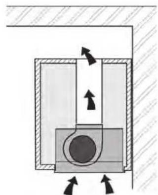
In the Filtering version (Fig. 1), the air and vapours conveyed by the appliance are depurated by charcoal filter and recirculated around the room. ATTENTION: Using the hood as a filtering one it is necessary to use the charcoal filters that purifies the air sent back into the room.
In the Ducting version (Fig. 2), cooking vapours and odours are conveyed straight outside by a disposal duct which passes through the wall/ceiling. Use of charcoal filters is therefore unnecessary.
Decide at the beginning which type of installation to adopt.
Your apparatus is supplied in the filtering version so that if you want to install the apparatus in the duction version you must remove the carbon filters.
This apparatus conforms to the 16.08.89 regulation relating to the limitation of radio-electric disturbances (EC Directive n./6.889 modified by the EC Directive 8/.308.).
Fig. 1
natural_image
Cross-sectional diagram of a mechanical or electrical component with directional arrows indicating movement (no text or symbols)Fig. 2

natural_image
Cross-sectional diagram of a mechanical or hydraulic system with directional arrows indicating flow or movement (no text or labels)INSTALLATION
It is advisable to entrust the installation operations to specialised personnel.
Installation in filtering version
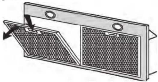
To facilitate installation, before starting remove the grease filter/s: press inward on the clamp at the handle and pull the filter downward (Fig. 3).
Fig. 3a

natural_image
Diagram of a double-door air vent with mesh grating and ventilation slots (no text or symbols)Fig. 3b

natural_image
Diagram of a mesh fan or vent with a handle, showing internal structure and mounting points (no text or symbols)Cut a hole in the bottom of the pensile cupboard in order to settle the appliance (Fig. 4).
Install the wiring system.
Insert the appliance in the hole (Fig. 4)
Tighten the 2 screws inside the appliance (Fig. 5) until it fits snug on the bottom of the wall unit. Avoid tightening the two screws with excessive force.
To the air venting flange of the apparatus connect a proper pipe that can convey the air to the upper part of the pensile cupboard. Make the electrical connection of the hood by means of the power supply cable.
Fig. 4

Installation in ducting version
Cut a hole in the bottom of the pensile cupboard in order to settle the appliance (Fig.4).
Install the wiring system and prepare the air venting hole.
Insert the appliance in the hole (Fig. 4)
Tighten the 2 screws inside the appliance (Fig. 5) until it fits snug on the bottom of the wall unit. Avoid tightening the two screws with excessive force.
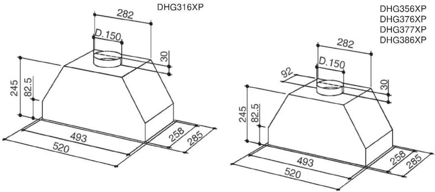
To get optimal conditions the air venting pipe should: be as short as possible, have the lowest number of bends (max bend angle: 90°), be made of material approved by local authorities (according to the State), have its inner side as regular and smooth as possible. It is moreover recommended to avoid drastic changes of pipe cross section (recommended diameter: 150 mm).
Using a proper pipe, connect the air venting flange of the apparatus to the air venting hole you made beforehand.
Make the electrical connection of the hood by means of the power supply cable.
FUNCTIONING OF THE APPARATUS
Depending on the model, the unit is equipped with the following controls:
C -II speed switch - Pressing once more the timer starts working: it will turn the motor OFF after a 10' working time: the led blinks for all this time
D -III speed switch - The timer works as for switch C
E -IV speed switch - The timer works as for switch C.
At the end of a working time of about 30 hours, all the leds blink all together to tell that the grease filters must be cleaned. After the cleaned filters are on again, press one of the three speed switches to allow the counting to start again.
DHG316XP
CONTROLS - Fig. 7:
A -Light ON/OFF switch
B -Motor ON/OFF - I speed switch
C -II speed switch
D -III speed switch
E - motor on light.
Fig. 6

Fig. 7

Technical data - DHG316XP:
- 1 Motor - power 135W
- Voltage: 230-240V single phase
- 2 halogen lamps 20W
- Supplied with 150 cm electricity supply cable with plug.
- Gross weight: Kg.8,4
- Net weight: Kg.6,9
- 1 metallic grease filter
Technical data - DHG376XP:
- 1 Motor - power 300W
- Voltage: 230-240V single phase
- 2 halogen lamps 20W
- Supplied with 150 cm electricity supply cable with plug.
- Gross weight: Kg.10,4
- Net weight: Kg.8,9
- 1 metallic grease filter
- 1 Motor - power 300W
- Voltage: 230-240V single phase
- 2 halogen lamps 20W
- Supplied with 150 cm electricity supply cable with plug.
- Gross weight: Kg.8,2
- Net weight: Kg.7,2
- 2 metallic grease filters
Technical data - DHG356XP:
- 1 Motor - power 155W
- Voltage: 230-240V single phase
- 2 halogen lamps 20W
- Supplied with 150 cm electricity supply cable with plug.
- Gross weight: Kg.8,4
- Net weight: Kg.6,9
- 1 metallic grease filter
Technical data - DHG377XP:
- 1 Motor - power 300W
- Voltage: 230-240V single phase
-2 halogen lamps 20W - Supplied with 150 cm electricity supply cable with plug.
- Gross weight: Kg.10,5
- Net weight: Kg.9,5
- 2 metallic grease filters
Dimensions (Fig. 8)
Fig. 8
While connecting the electricity make sure that the tension is that indicated in the technical lable.
Before proceeding to cleaning or maintenance operations remove the tension.
Connecting the electricity must be performed by a specialised technician in conformity with the regulation in force.
This apparatus is constructed so as to belong to the I insulation class and therefore needs grounding.
MAINTENANCE
REMOVE THE TENSION AT THE HOOD (PLUG or SWITCH) BEFORE ANY OPERATION-
Thorough servicing guarantees correct and long-lasting operation.
-Maintenance of the casing:
Avoid products containing abrasives when cleaning the casing.
-Maintenance of the anti-grease filters:
The anti-grease filters require regular maintenance and must be cleaned periodically every two months.
Remove the anti-grease filters in correspondence with the handle, push the stop inward and pull the filter downwards (Fig.9). Wash them with a normal neutral product in commerce, then rinse abundantly and dry. The washing can be carried out in the dishwasher making sure not to let the filters make contact with dirty or silver dishes. Remount the anti-grease filters.
Fig. 9a
natural_image
Diagram of a double door with mesh pattern and directional arrows indicating movement (no text or symbols)Fig. 9b

natural_image
Diagram of a metal grate with a mesh pattern and a downward arrow indicating force or direction (no text or symbols)-Maintenance of the carbon filters:
If you are using the filtering version apparatus, the carbon filters (Ref.: DHK306AP1) need to be changed every six months on average depending on the use made of the hood.
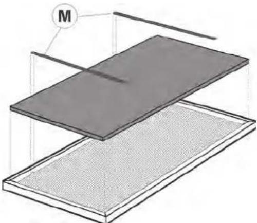
The anti-grease filters (Fig. 9a, 9b) need to be removed first in order to remove the carbon filters. Remove the two metal filter retainers (M) and position the charcoal filter inside the grease filter; fit the two filter retainers back on again to secure the charcoal filter (Fig.10). Change the carbon filters and remount the anti-grease filters.
Fig. 10
natural_image
3D diagram of layered material structure with labeled component M (no text or symbols beyond label)-Changing the halogen lamps:
To change the halogen bulbs open the cover levering from the proper slots (Fig.11). Change with a lamp of the same kind. CAUTION: Do not handle glass bulb with bare hands.
Fig. 11

natural_image
Technical diagram of a bathroom sink with a magnified inset showing a circular component (no text or symbols)SCHÉMA ÉLECTRIQUE - WIRING DIAGRAM - ELEKTRISCHER SCHALTPLAN SCHEMA ELETTRICO - ESQUEMA ELÉCTRICO - ESQUEMA ELÉCTRICO ELEKTRISCH SCHEMA
DHG377XP
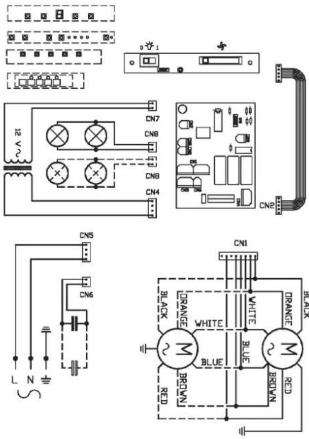
DHG386XP
DHG376XP

SCHÉMA ÉLECTRIQUE - WIRING DIAGRAM - ELEKTRISCHER SCHALTPLAN SCHEMA ELETTRICO - ESQUEMA ELÉCTRICO - ESQUEMA ELÉCTRICO ELEKTRISCH SCHEMA
DHG316XP

DHG356XP


- ATTENTION: This appliance must be grounded.
- USE
- MAINTENANCE
- DESCRIPTION OF THE APPLIANCE
- INSTALLATION
- Installation in filtering version
- Installation in ducting version
- FUNCTIONING OF THE APPARATUS
- DHG316XP
- CONTROLS - Fig. 7:
- Technical data - DHG316XP:
- Technical data - DHG376XP:
- Technical data - DHG356XP:
- Technical data - DHG377XP:
- REMOVE THE TENSION AT THE HOOD (PLUG or SWITCH) BEFORE ANY OPERATION-
- -Maintenance of the casing:
- -Maintenance of the anti-grease filters:
- -Maintenance of the carbon filters:
- -Changing the halogen lamps:
- SCHÉMA ÉLECTRIQUE - WIRING DIAGRAM - ELEKTRISCHER SCHALTPLAN SCHEMA ELETTRICO - ESQUEMA ELÉCTRICO - ESQUEMA ELÉCTRICO ELEKTRISCH SCHEMA
Brand : DE DIETRICH
Model : DHG377XP1
Category : Range hood