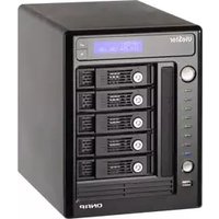
VS-5012 - Server QNAP - Free user manual and instructions
Find the device manual for free VS-5012 QNAP in PDF.


| Product Type | Server (Video Surveillance / NAS) |
| Brand | QNAP |
| Model | VS-5012 |
| Form Factor | Rackmount (19 inches, 1U/2U) |
| Dimensions (W x D x H) | 482 x 350 x 44 mm (approximate) |
| Weight | 10 kg (approximate) |
| Power Supply | 500W, redundant optional |
| Main Functions | Video surveillance management, network storage, RAID support, IP camera recording |
| Processor | Intel Xeon E3 or similar (approximate) |
| Memory | 8 GB DDR4, expandable to 32 GB |
| Drive Bays | 12 x SATA 3.5-inch (hot-swappable) |
| Network Ports | 4 x Gigabit Ethernet (RJ-45) |
| USB Ports | 2 x USB 3.0, 2 x USB 2.0 |
| Operating Temperature | 0°C to 40°C |
| Humidity | 5% to 95% non-condensing |
| Safety Certifications | CE, FCC, UL, VCCI |
| Maintenance | Dust filters accessible, fan and drive replacement |
| Cleaning | Use lint-free cloth, avoid liquids |
| Spare Parts | Power supply unit, fan module, drive tray |
| Reparability | Modular components, user-replaceable drives, fans |
Frequently Asked Questions - VS-5012 QNAP
User questions about VS-5012 QNAP
0 question about this device. Answer the ones you know or ask your own.
Ask a new question about this device
Download the instructions for your Server in PDF format for free! Find your manual VS-5012 - QNAP and take your electronic device back in hand. On this page are published all the documents necessary for the use of your device. VS-5012 by QNAP.
USER MANUAL VS-5012 QNAP
©Copyright 2009-2010. QNAP Systems, Inc. All Rights Reserved.
Thank you for choosing QNAP products! This user manual provides detailed instructions of using the product. Please read carefully and start to enjoy the powerful functions of the product!
• VioStor NVR is hereafter referred to as VioStor.
- This manual provides the description of all the functions of VioStor NVR. The product you purchased may not support certain functions dedicated to specific models.
Legal Notices
©Copyright 2009-2010. QNAP Systems, Inc. All Rights Reserved.
All the features, functionality, and other product specifications are subject to change without prior notice or obligation. Information contained herein is subject to change without notice.
QNAP and the QNAP logo are trademarks of QNAP Systems, Inc. All other brands and product names referred to are trademarks of their respective holders. Further, the ® or ™ symbols are not used in the text.
LIMITED WARRANTY
In no event shall the liability of QNAP Systems, Inc. (QNAP) exceed the price paid for the product from direct, indirect, special, incidental, or consequential software, or its documentation. QNAP makes no warranty or representation, expressed, implied, or statutory, with respect to its products or the contents or use of this documentation and all accompanying software, and specifically disclaims its quality, performance, merchantability, or fitness for any particular purpose. QNAP reserves the right to revise or update its products, software, or documentation without obligation to notify any individual or entity.
CAUTION
- Back up your system periodically to avoid any potential data loss. QNAP disclaims any responsibility of all sorts of data loss or recovery.
- Should you return any components of the product package for refund or maintenance, make sure they are carefully packed for shipping. Any form of damages due to improper packaging will not be compensated.
Important Notice
- Reading instructions
Please read the safety warnings and user manual carefully before using this product.
- Power supply
This product can only be used with the power supply provided by the manufacturer.
- Service
Please contact qualified technicians for any technical enquires. Do not repair this product by yourself to avoid any voltage danger and other risks caused by opening this product cover.
- Warning
To avoid fire or electric shock, do not use this product in rain or humid environment. Do not place any objects on this product.
Regulatory Notice

FCC STATEMENT
This equipment has been tested and found to comply with the limits for a Class B digital device, pursuant to Part 15 of FCC Rules. These limits are designed to provide reasonable protection against harmful interference in a residential installation. This equipment generates, uses, and can radiate radio frequency energy and, if not installed and used in accordance with the instructions, may cause harmful interference to radio communications. However, there is no guarantee that interference will not occur in particular installation. If this equipment does cause harmful interference to radio or television reception, which can be determined by turning the equipment off and on, the user is encouraged to try to correct the interference by one or more of the following measures:
- Reorient or relocate the receiving antenna.
- Increase the separation between the equipment and receiver.
- Connect the equipment into an outlet on a circuit different from that to which the receiver is connected.
- Consult the dealer or an experienced radio/television technician for help.
The changes or modifications not expressly approved by the party responsible for compliance could void the user's authority to operate the equipment.
Shielded interface cables, if any, must be used in order to comply with the emission limits.
CE CE NOTICE
Class B only.
Table of Contents
TABLE OF CONTENTS ....5
SAFETY WARNING....9
CHAPTER 1. INTRODUCTION....11
1.1 OVERVIEW....11
1.2 HARDWARE ILLUSTRATION....12
1.2.1 VS-8040U-RP/VS-8032U-RP/VS-8024U-RP....12
1.2.2 VS-8040/VS-8032/VS-8024....13
1.2.3 VS-6020 Pro/VS-6016 Pro/VS-6012 Pro 14
1.2.4 VS-5020/VS-5012....15
1.2.5 VS-4016U-RP Pro/VS-4012U-RP Pro/VS-4008U-RP Pro....16
1.2.6 VS-4016 Pro/VS-4012 Pro/VS-4008 Pro 17
1.2.7 VS-4016U-RP 18
1.2.8 VS-2012 Pro/VS-2008 Pro....19
1.2.9 VS-2012/VS-2008....20
1.2.10 VS-201P/V 21
1.2.11 NVR-104P/V 22
1.2.12 VS-101P/V 23
CHAPTER 2. INSTALL VIOSTOR....24
2.1 PERSONAL COMPUTER REQUIREMENTS....24
2.2 HARD DISK DRIVES COMPATIBILITY LIST....26
2.3 IP CAMERAS COMPATIBILITY LIST....26
2.4 CHECK SYSTEM STATUS 27
2.5 SYSTEM CONFIGURATION....30
CHAPTER 3. USE VIOSTOR BY LOCAL DISPLAY....35
3.1 QUICK CONFIGURATION ....37
3.2 MONITORING....44
3.3 VIDEO PLAYBACK 52
CHAPTER 4. USE VIOSTOR BY WEB-BASED INTERFACE....54
4.1 CONNECT TO VIOSTOR....54
4.2 MONITORING PAGE....56
4.2.1 Live Video Window....60
4.2.2 Display Mode....62
4.2.3 PTZ Camera Control Panel....62
4.2.4 Multi-server Monitoring....63
4.2.5 Monitor Settings 64
4.2.6 Auto Cruising....66
CHAPTER 5. PLAYBACK THE VIDEO FILES ....70
5.1 USE THE WEB-BASED PLAYBACK INTERFACE (VIOSTOR PLAYER) 70
5.1.1 Connect to Server for Playback....71
5.1.2 Play Video Files from Your Computer....81
5.1.3 Quad-view Playback....82
5.1.4 Intelligent Video Analytics (IVA) 84
5.1.5 Convert to AVI File....91
5.2 DIGITAL WATERMARKING....95
5.2.1 Export Files with Digital Watermark 95
5.2.2 Watermark Proof....98
5.3 ACCESS THE RECORDING DATA 100
5.3.1 Windows Network Neighbourhood (SMB/CIFS)....101
5.3.2 Web File Manager (HTTP)....101
5.3.3 FTP Server (FTP)....102
CHAPTER 6. SYSTEM ADMINISTRATION....103
6.1 QUICK CONFIGURATION....106
6.2 SYSTEM SETTINGS....111
6.2.1 Server Name 111
6.2.2 Date & Time....112
6.2.3 View System Settings....113
6.3 NETWORK SETTINGS 114
6.3.1 TCP/IP Configuration 114
6.3.2 DDNS (Dynamic Domain Name) Service 120
6.3.3 File Services 121
6.3.4 Host Access Control....122
6.3.5 Protocol Management....123
6.3.6 View Network Settings 124
6.4 DEVICE CONFIGURATION....125
6.4.1 SATA Disk 125
6.4.2 RAID Management Tool 128
6.4.3 USB Disk 130
6.4.4 UPS....131
6.5 USER MANAGEMENT....132
6.5.1 Create user....134
6.5.2 Edit User....135
6.5.3 Delete User....135
6.5.4 User Access Rights Comparison....136
6.6 CAMERA SETTINGS....138
6.6.1 Camera Configuration....138
6.6.2 Recording Settings....141
6.6.3 Schedule Settings....143
6.6.4 Alarm Settings....144
6.6.5 Advanced Settings....162
6.7 SYSTEM TOOLS....164
6.7.1 Alert Notification....164
6.7.2 SMSC Settings....165
6.7.3 Restart/Shut Down....167
6.7.4 Hardware Settings 168
6.7.5 System Update....171
6.7.6 Backup/Restore/Reset Settings....173
6.7.7 Remote Replication....174
6.7.8 Hard Disk SMART....178
6.7.9 E-map....180
6.7.10 Ping Test 180
6.7.11 Advanced System Settings....181
6.8 LOGS & STATISTICS....182
6.8.1 System Event Logs....182
6.8.2 Surveillance Logs 182
6.8.3 On-line Users List....183
6.8.4 Historical Users List....183
6.8.5 System Connection Logs....184
6.8.6 System Information....184
CHAPTER 7. SYSTEM MAINTENANCE....185
7.1 RESET THE ADMINISTRATOR PASSWORD AND NETWORK SETTINGS....185
7.2 POWER OUTAGE OR ABNORMAL SHUTDOWN 186
7.3 HOT SWAPPING HARD DISK DRIVES (RAID CONFIGURATION)....186
CHAPTER 8. LCD PANEL....187
CHAPTER 9. TROUBLESHOOTING....193
APPENDIX A DYNAMIC DOMAIN NAME REGISTRATION....196
APPENDIX B CONFIGURATION EXAMPLES....200
TECHNICAL SUPPORT....205
GNU GENERAL PUBLIC LICENSE 206
Safety Warning
- This product can operate normally in the temperature of 0° C– 40° C and relative humidity of 0%–90%. Please make sure the environment is well-ventilated.
- The power cord and devices connected to this product must provide correct supply voltage.
- Do not place this product in direct sunlight or near chemicals. Make sure the temperature and humidity of the environment are in optimized level.
- Unplug the power cord and all connected cables before cleaning. Wipe this product with a wet towel. Do not use chemical or aerosol to clean this product.
- Do not place any objects on this product for the server's normal operation and to avoid overheat.
- Use the flat head screws in the product package to lock the hard disks in this product when installing hard disks for proper operation.
- Do not place this product near any liquid.
- Do not place this product on any uneven surface to avoid falling off and damage.
- Make sure the voltage is correct in your location when using this product. If you are not sure about the voltage, please contact the distributor or the local power supply company.
- Do not place any object on the power cord.
- Do not attempt to repair this product in any occasions. Improper disassembly of the product may expose you to electric shock or other risks. For any enquiries, please contact the distributor.
- The chassis models should only be installed in the server room and maintained by the authorized server manager or IT administrator. The server room is locked by key or keycard access and only certified staff is allowed to enter the server room.

Warning:
- Danger of explosion if battery is incorrectly replaced. Replace only with the same or equivalent type recommended by the manufacturer. Dispose of used batteries according to the manufacturer's instructions.
- Do NOT touch the fan inside the system to avoid serious injuries.
Chapter 1. Introduction
1.1 Overview
QNAP VioStor (hereafter referred to as NVR or VioStor) is the high performance network surveillance solution for network-based monitoring of IP cameras, video recording, playback, and remote data access. Up to 120 channels from multiple QNAP NVR servers can be monitored simultaneously. The NVR supports IP-based cameras from AXIS, ACTi, A-MTK, Arecont Vision, AVTECH, Canon, Cisco, CNB, DIGITUS, D-Link, EDIMAX, ELMO, EtroVision, GANZ, Hikvision, iPUX, IQeye, LevelOne, Messoa, MOBOTIX, Nakayo, Panasonic BB/BL/i-Pro, SANYO, SONY, TOSHIBA, TRENDnet, VIVOTEK, VIOSECURE, and Y-CAM. Users can select to record the video in H.264, MxPEG, MPEG-4, or MJPEG video compression. The NVR offers diversified display modes and recording features, e.g. schedule recording, alarm recording, alarm recording schedule. The NVR also supports data search by date and time, timeline, event, and intelligent video analytics (IVA), including motion detection, missing object, foreign object, out of focus, and camera occlusion. All the functions can be configured by the IE web browser.
1.2 Hardware Illustration
1.2.1 VS-8040U-RP/VS-8032U-RP/VS-8024U-RP

- LED indicators: Status, LAN, USB, HDD1-8
- Power button
- Select button
- Enter button
- Power connector
- Password & network settings reset button
- RS-232
- VGA
- USB x 4
- Giga LAN x 2
1.2.2 VS-8040/VS-8032/VS-8024


- One touch auto video backup button
- USB
- LED indicators: Status, LAN, USB, HDD1-8
- Power button
- Select button
- Enter button
- Power connector
- Giga LAN x 2
- USB × 4
- RS-232
- VGA
- Password & network settings reset button
- Kensington security slot
1.2.3 VS-6020 Pro/VS-6016 Pro/VS-6012 Pro
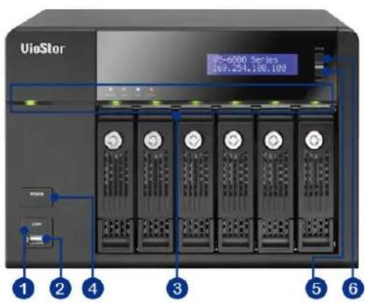
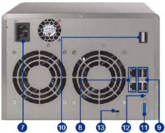
- One touch auto video backup button
- USB
- LED indicators: Status, LAN, USB, eSATA, HDD1-6
- Power button
- Select button
- Enter button
- Power connector
- Giga LAN x 2
- USB x 4
- eSATA x 2 (reserved)
- VGA
- Password & network settings reset button
- Kensington security slot
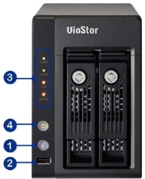
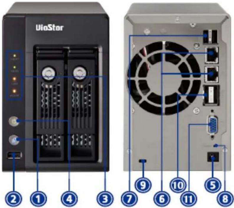
1.2.4 VS-5020/VS-5012
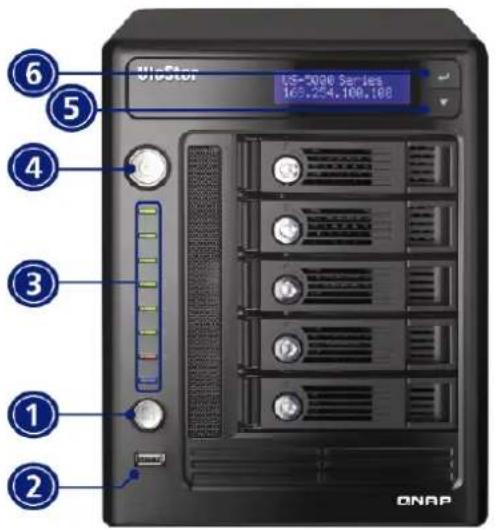

- One touch auto video backup button
- USB
- LED indicators: USB, Status, HDD1-5, LAN
- Power button
- Select button
- Enter button
- Power connector
- Giga LAN x 2
- USB × 4
- eSATA (reserved)
- VGA
- RS-232 port
- Password & network settings reset button
- Kensington security slot
1.2.5 VS-4016U-RP Pro/VS-4012U-RP Pro/VS-4008U-RP Pro

- One touch auto video backup button
- USB
- LED indicators: Status, LAN, USB, eSATA, HDD1-4
- Power button
- Power connector
- Giga LAN x 2
- USB × 4
- eSATA x 2 (reserved)
- VGA
- Password & network settings reset button
1.2.6 VS-4016 Pro/VS-4012 Pro/VS-4008 Pro

- One touch auto video backup button
- USB
- LED indicators: Status, LAN, USB, eSATA, HDD1-4
- Power button
- Select button
- Enter button
- Power connector
- Giga LAN x 2
- USB × 4
- eSATA x 2 (Reserved)
- VGA
- Password & network settings reset button
- Kensington security slot
1.2.7 VS-4016U-RP

- One touch auto video backup button
- USB
- LED indicators: USB, Status, HDD1-HDD4, LAN
- Power button
- Power connector
- Giga LAN x 2
- USB x 2
- Password & network settings reset button
- VGA
1.2.8 VS-2012 Pro/VS-2008 Pro

- One touch auto video backup button
- USB
- LED indicators: HDD1, HDD2, LAN, eSATA
- Power button
- Power connector
- Giga LAN x 2
- USB x 2
- eSATA x 2 (reserved)
- VGA
- Password & network settings reset button
- Kensington security slot
1.2.9 VS-2012/VS-2008
- One touch auto video backup button
- USB
- LED indicators: HDD1, HDD2, LAN, eSATA
- Power button
- Power connector
- Giga LAN x 2
- USB × 2
- Password & network settings reset button
- Kensington security slot
- eSATA x 2 (reserved)
- VGA
1.2.10 VS-201P/V

- One touch auto video backup button
- USB
- LED indicators: USB, status, HDD1, HDD2, LAN, and power
- Power button
- Power connector
- Giga LAN
- USB × 2
- Password & network settings reset button !!
- Kensington security slot
1.2.11 NVR-104P/V

- One touch auto video backup button
- USB
- LED indicators
- Power button
- USB x 2
- eSATA port
- Giga LAN
- Password & network settings reset button
- Power connector
- Kensington security slot
1.2.12 VS-101P/V

- One touch auto video backup button
- USB
- LED indicators
- Power button
- Power connector
- Giga LAN
- USB x 2
- Password & network settings reset button
- Kensington security slot
- eSATA port (reserved)
Chapter 2. Install VioStor
For the information of the hardware installation, please refer to the "Quick Installation Guide" in the product package.
2.1 Personal Computer Requirements
For better system performance, your computer should at least fulfil the following requirements:
| No. of Channels | Format | CPU | Others |
| 4 | M-JPEG Intel Pentium 4 | CPU,2.4GHz or above | Operation system: Microsoft Windows 7, Vista, XPMemory: 2GB or aboveNetwork port: 100Mbps Ethernet port or aboveWeb browser: Microsoft Internet Explorer 6.0 or aboveCD-ROM driveRecommended resolution: 1024 x 768 pixels or above |
| MPEG-4/MxPEG/H.264 | Dual core CPU,2.0GHz or above | ||
| 8 | M-JPEG Intel Pentium 4 | CPU,2.8GHz or above | |
| MPEG-4/MxPEG/H.264 | Dual core CPU,2.4GHz or above | ||
| 12 | M-JPEG Intel Pentium 4 | CPU,3.0GHz or above | |
| MPEG-4/MxPEG/H.264 | Dual core CPU,2.8GHz or above | ||
| 16 | M-JPEG Dual core CPU, | 2.4GHz or above | |
| MPEG-4/MxPEG/H.264 | Quad core CPU,2.33GHz or above | ||
| 20 | M-JPEG Dual core CPU, | 2.6GHz or above | |
| MPEG-4/MxPEG/H.264 | Quad core CPU,2.6GHz or above | ||
| 40 | M-JPEG | Quad2.33GHz or above | core CPU |
| MPEG-4/MxPEG/H.264 | Core i7 CPU 2.8GHz or above |
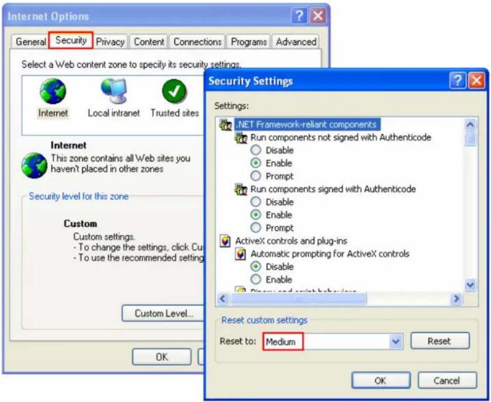
Security Settings of the Web Browser
Please make sure the security level of the IE browser in Internet Options is set to Medium or lower.
2.2 Hard Disk Drives Compatibility List
This product works with 2.5-inch/3.5-inch SATA hard disk drives from popular hard disk brands. For the HDD compatibility list, please visit http://www.qnapsecurity.com/pro_compatibility.asp

QNAP disclaims any responsibility for product damage/malfunction or data loss/recovery due to misuse or improper installation of hard disks in any occasions for any reasons.
2.3 IP Cameras Compatibility List
For the information of supported IP camera models, please visit http://www.qnapsecurity.com/pro_compatibility_camera.asp
2.4 Check System Status
LED Display & System Status Overview
| LED | Colour | LED Status Description |
| System Status | Red/Green | Flashes green and red alternately every 0.5 sec |
| Red | ||
| Flashes red every 0.5 sec | ||
| Flashes green every 0.5 sec | ||
| Green The Off | ||
| LAN Orange | Orange The NVR is connected to the network | |
| Flashes orange The NVR is being accessed from the network |
| HDD | Red/Green | Flashes red | The hard drive data is being accessed and a read/write error occurs during the process |
| Red A hard drive read/write error occurs | |||
| Flashes green | The hard drive data is being accessed | ||
| Green The hard drive can be accessed | |||
| USB Blue | Flashes blue every 0.5 sec | 1) A USB device is detected2) A USB device is being removed from the NVR3) The USB device connected to the front USB port of the NVR is being accessed4) The NVR data is being copied to the external USB device | |
| Blue | The USB device connected to the front USB port of the NVR is ready | ||
| Off | The NVR has finished copying the data to the USB device connected to the front USB port* | ||
| eSATA† Orange | Flashes The | eSATA device is being accessed | |
* Not applicable to 1-bay models
† The eSATA port is available on certain models only. Please refer to
http://www.qnap.com/ for more information.
# 4-bay models or above only
Beep Alarm (beep alarm can be disabled in "System Tools" > "Hardware Settings")
| Beep sound No. | of Times | Description |
| Short beep (0.5 sec) 1 | 1) The NVR is starting up2) The NVR is being shut down (software shutdown)3) The user presses the reset button to reset the NVR4) The system firmware has been updated | |
| Short beep (0.5 sec) 3 | The user tries to copy the NVR data to the external storage device from the front USB port, but the data cannot be copied. | |
| Short beep (0.5 sec), long beep (1.5 sec) | 3, every 5 min | The system fan is out of function* |
| Long beep (1.5 sec) | 2 | 1) The disk volume is going to be full2) The disk volume has reached its full capacity3) The hard drives on the NVR are in degraded mode4) The user starts the HDD rebuilding process |
| 1 | 1) The NVR is turned off by force shutdown (hardware shutdown)2) The NVR has been turned on successfully and is ready |
* Not applicable to 1-bay models
2.5 System Configuration
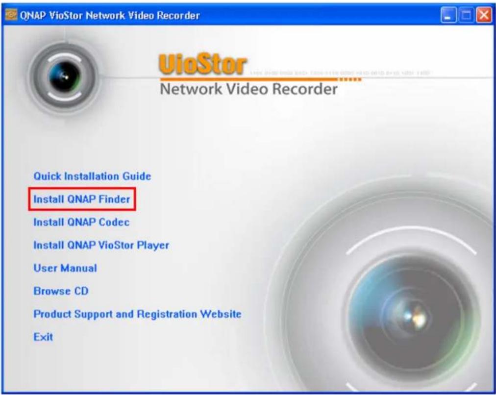
Install Finder
- Run the product CD, the following menu is shown. Click "Install Finder".
-
Follow the instructions to install Finder. Upon successful installation, run Finder. If Finder is blocked by your firewall, unblock it.
-
Finder detects the VioStor servers on the local network. If the server has not been initialised, you will be prompted to perform quick setup. Click "Yes" to continue.
Note: If VioStor is not found, click "Refresh" to try again.
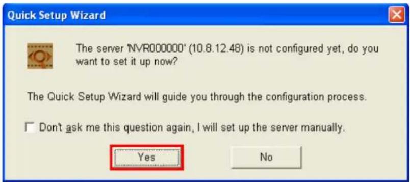
- You must enter the administrator name and password to perform quick setup.
The default administrator name and password are as below:
Use name: admin*
Password: admin
*If you are using the VS-201/VS-101/NVR-104, the default login name is "administrator" and the login password is "admin".
Note: Make sure all the IP cameras are configured and connected to the network.
- The quick configuration page will be shown. Click "Continue" and follow the instructions to finish the configuration. For further information, please refer to Chapter 6.1.

- Click "Start installation" to execute the quick configuration.
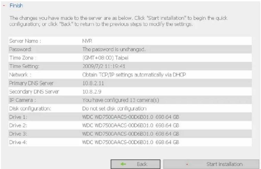
- After the quick configuration, you can start to use VioStor. Click "Start Monitoring" to view the live video from the IP cameras or click "Close" to return to the home page of the system administration.

- The first time you connect to the monitoring page of VioStor, install the ActiveX add-on.

You can view the live video from the IP cameras configured on VioStor and the recording status of each channel.

Chapter 3. Use VioStor by Local Display
You can connect to VioStor by local display via the VGA connector to perform PC-less quick configuration, monitoring, and video playback. To use this feature, you need to do the following:
- Make sure at least one hard disk drive has been installed on VioStor.
- Connect VioStor to the network.
- Make sure the IP cameras have been configured and connected to the network.
- Connect a VGA monitor or TV (suggested video output resolution: 1920 x 1080) to VioStor via the VGA connector.
- Connect a USB mouse and a USB keyboard (optional) to VioStor via the USB ports.
- Turn on VioStor.
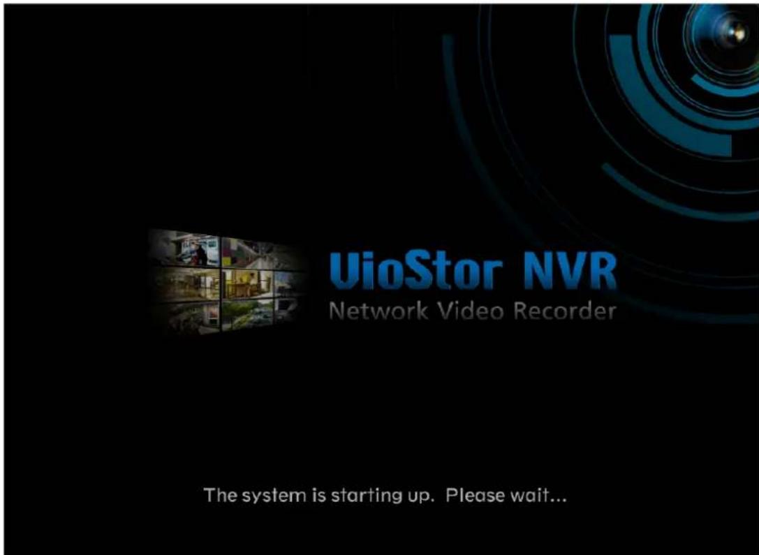
When VioStor is turned on, the login screen will be shown. Select the language. Enter the administrator name and password. If your VioStor has not been configured, skip the login page and enter Quick Configuration (refer to Chapter 3.1).
Default user name: admin
Password: admin

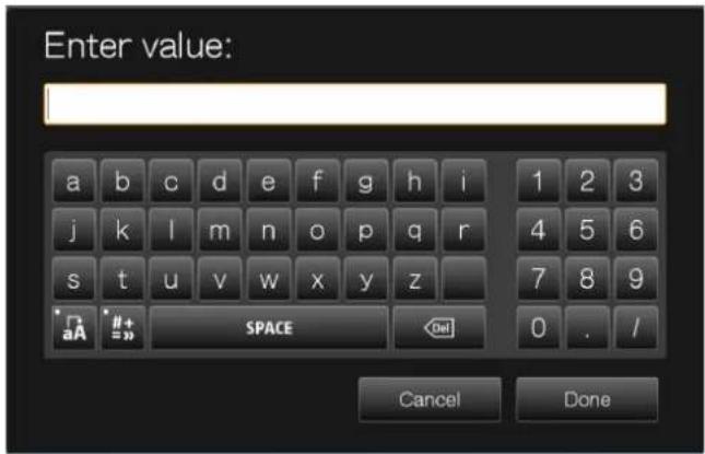
Click the keyboard icon to enter the necessary information if you do not have a USB keyboard.
The monitoring page will be shown upon successful login, refer to Chapter 3.2 for details.
3.1 Quick Configuration
If the NVR has not been configured, Quick Configuration Wizard will be shown. Follow the instructions of the wizard to complete the system setup.
Note: All the changes will be effective only after you apply the settings in the last step.
- The system information will be shown. Select the language and click "Next".

- Change the admin password or use the default password (admin).

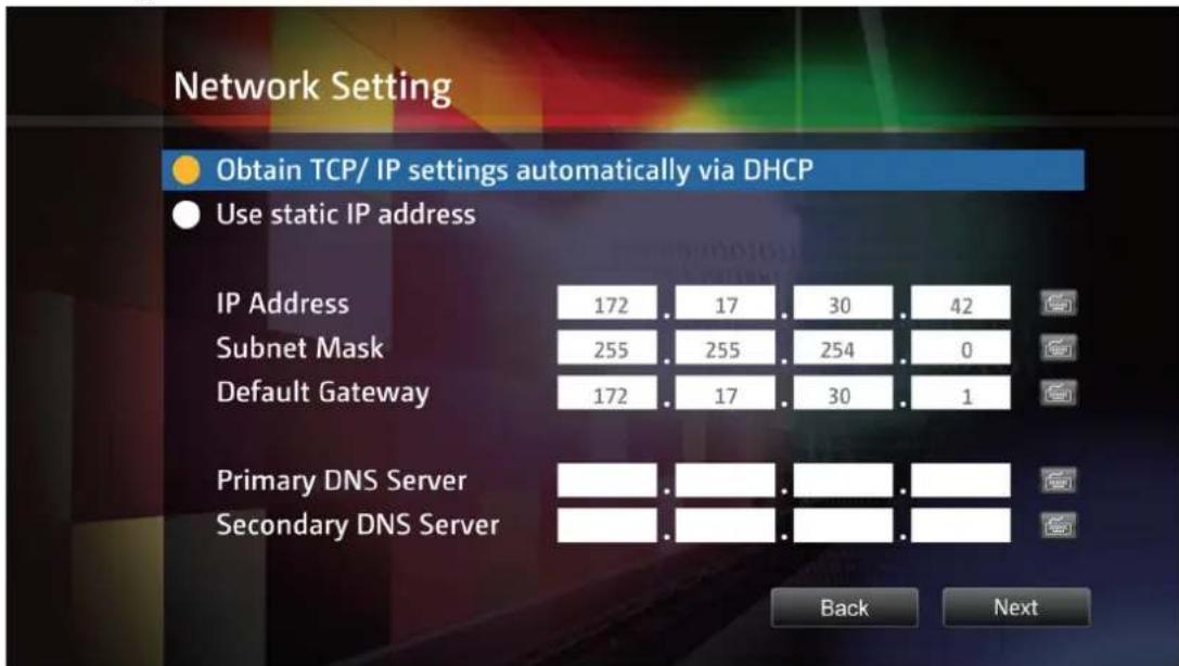
- Select to obtain the network settings automatically or enter the network settings.
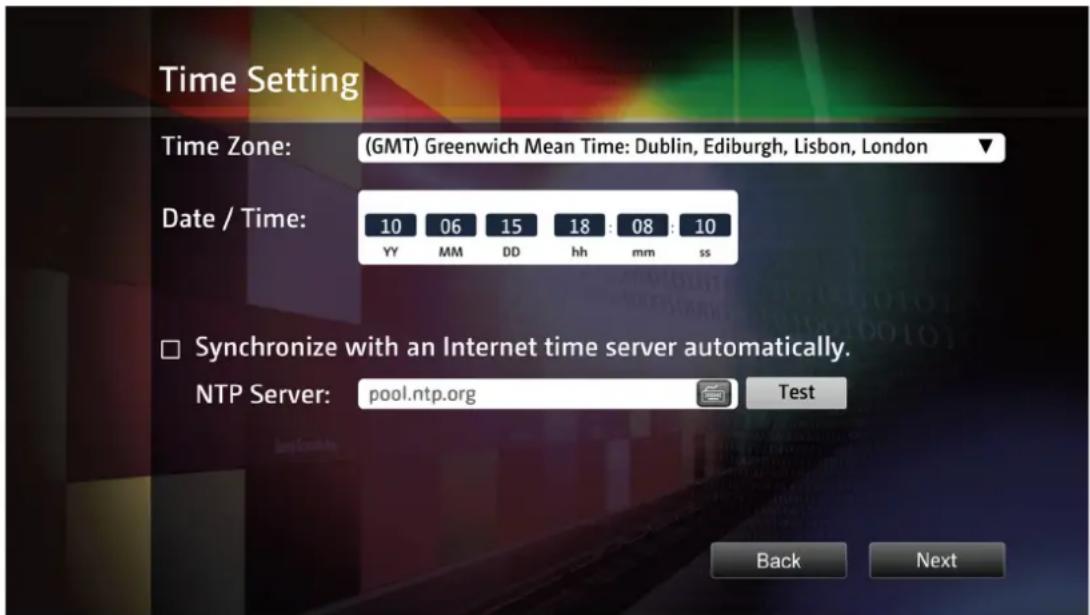
- Enter the date and time settings. You can select to synchronize the server time with an Internet time server. If you enter a domain name for the NTP server, make sure you have set up a correct DNS server.
- Select the disk configuration. Click "Disk Information" to view the hard disk drive details. Note that all the disk data will be deleted when you select to initialize the disk volume.

- Configure the IP camera settings. If no IP cameras have been set, you will be prompted to search for the cameras on the local network.
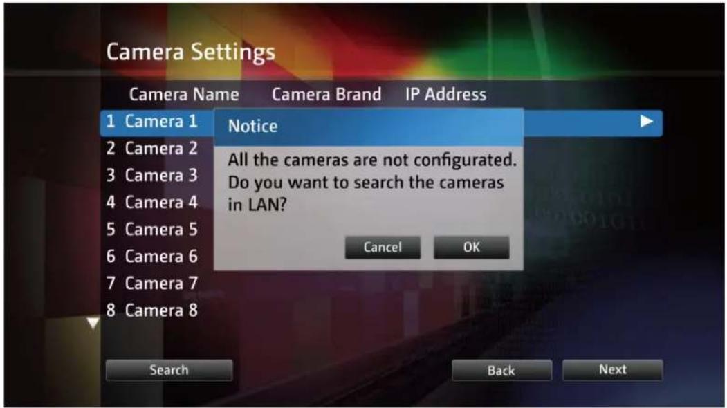
The cameras found will be shown. Select the IP cameras and click "Add" to add the channels.

To manually add an IP camera or edit the camera settings, click ▶.

Enter the camera settings. Click "Test" to test the connection. Click "Remove" to delete the camera.

To edit the recording settings, click ▶ next to "Recording Settings". Define the recording settings and click "OK".

- Verify the settings and click "Next" to initialize the server.
Finish
The changes you have made to the server are as below. Click "Next" to begin the quick configuration; or click "Back" to return to the previous steps to modify the settings.
Model Name: VS-5020
Password: The password is unchanged.
Network: Obtain TCP/IP settings automatically via...
Date/ Time: 2010/06/15 06:06:10
Time Zone: (GMT+08:00) Taipei
Back
Next
- When the initialization completes, you can start to use VioStor. Click "Start Monitoring" to enter the monitoring screen.
System Initialization
The system is being configured, do NOT power off the server or unplug the hard drive(s).
- Change the administrator password.
- Enter the IP address, subnet mask and default gateway for this server.
- Enter the date, time and time zone for this server.
- Initialize the disk volume on this server.
- Add the IP cameras to be recorded to this server.
Start Monitoring
3.2 Monitoring
Upon successful login, the monitoring screen will be shown. You can start to monitor the IP cameras, change the display mode, enable or disable manual recording, control PTZ cameras, and so on.

| Icon | Description |
 | Monitor:Click this icon to enter the monitoring page. |
 | Playback:Click this icon to enter the playback page. |
 | Hide left panel:Hide the panel on the left of the monitoring page. |
 | Show left panel:Show the panel on the left of the monitoring page. |
 | Logout:Logout VioStor. |
 | About:View the server name, NVR model, and firmware version. |
 | Manual recording:Enable or disable recording on the IP camera. The administrator can select to enable or disable this function in “Camera Settings” > “Recording Settings” on the web-based administration interface. |
 | Audio (optional):Turn on or off the audio support for the monitoring page. |

Event notification:
When the alarm recording is enabled and an event is detected, this icon will be shown. Click this icon to view the alert details. You can select to turn on or off the alert sound. To clear all the logs, click "Clear All".
The system event logs are shown in this dialog. Click 'Clear' to delete a log, or click 'Clear All' to delete all logs.
| Type | Camera | Date & Time | Log |
| Alarm | 0 | 2010-09-01 11:36:14 | Logical input TB * is triggered |
| Alarm | 0 | 2010-09-01 10:55:23 | Logical input TB * is triggered |
| Alarm | 0 | 2010-09-01 10:35:42 | Logical input ð is triggered |
| Alarm | 1 | 2010-09-01 09:33:32 | Event(s) Triggered on Camera 1. |
| Alarm | 1 | 2010-09-01 09:33:30 | Event(s) Triggered on Camera 1. |
| Alarm | 1 | 2010-09-01 09:33:29 | Event(s) Triggered on Camera 1. |
| Alarm | 1 | 2010-09-01 09:33:27 | Event(s) Triggered on Camera 1. |
| Alarm | 1 | 2010-09-01 09:33:26 | Event(s) Triggered on Camera 1. |
| Alarm | 1 | 2010-09-01 09:33:23 | Event(s) Triggered on Camera 1. |
| Alarm | 1 | 2010-09-01 09:33:21 | Event(s) Triggered on Camera 1. |
| Alarm | 1 | 2010-09-01 09:33:19 | Event(s) Triggered on Camera 1. |
| Alarm | 1 | 2010-09-01 09:33:18 | Event(s) Triggered on Camera 1. |
| Alarm | 1 | 2010-09-01 09:33:15 | Event(s) Triggered on Camera 1. |
| Alarm | 1 | 2010-09-01 09:33:13 | Event(s) Triggered on Camera 1. |
| Alarm | 1 | 2010-09-01 09:33:11 | Event(s) Triggered on Camera 1. |
| Alarm | 1 | 2010-09-01 09:33:09 | Event(s) Triggered on Camera 1. |
| Alarm | 1 | 2010-09-01 09:33:06 | Event(s) Triggered on Camera 1. |
□ Alert sound
Clear All
Close
PTZ Control Panel
The term "PTZ" stands for "Pan/Tilt/Zoom". If your IP camera supports PTZ, you can use the control panel on VioStor to adjust the viewing angel of the IP camera. These functions are available depending on the camera models. Please consult the camera's documentation for details. Note that the digital zoom function will be disabled when the PTZ function is in use.
 | Pan and tilt:If your PTZ camera supports pan and tilt functions, click these buttons to pan or tilt the camera. |
 | Preset positions:Select the preset position of the PTZ camera. |
 | Zoom in/Zoom out:If your PTZ camera supports zooming, click these buttons to zoom in or zoom out. |
 | Digital zoom:Select a channel and click this button to enable the digital zoom function. When enabled, you can click “+” to zoom in or “-” to zoom out. |
 | Focus control:Adjust the focus control of the PTZ camera. |
Display Mode
VioStor supports various display modes for monitoring. Click the correct icon to switch the display mode.
| Icon | Description |
 | Full screen |
 | Single-channel mode |
 | 4-channel mode |
 | 6-channel mode |
 | 8-channel mode |
 | 9-channel mode |
 | 10-channel mode |
 | 12-channel mode |
 | Select the display page number |
 | Sequential mode. This mode can be used with other display modes.Click to enable or disable sequential mode. Click to define the time interval of which the channels will be displayed. |
Live View Screen
Upon successful configuration of the IP cameras, you can enter the monitoring screen to view the live video from the cameras.
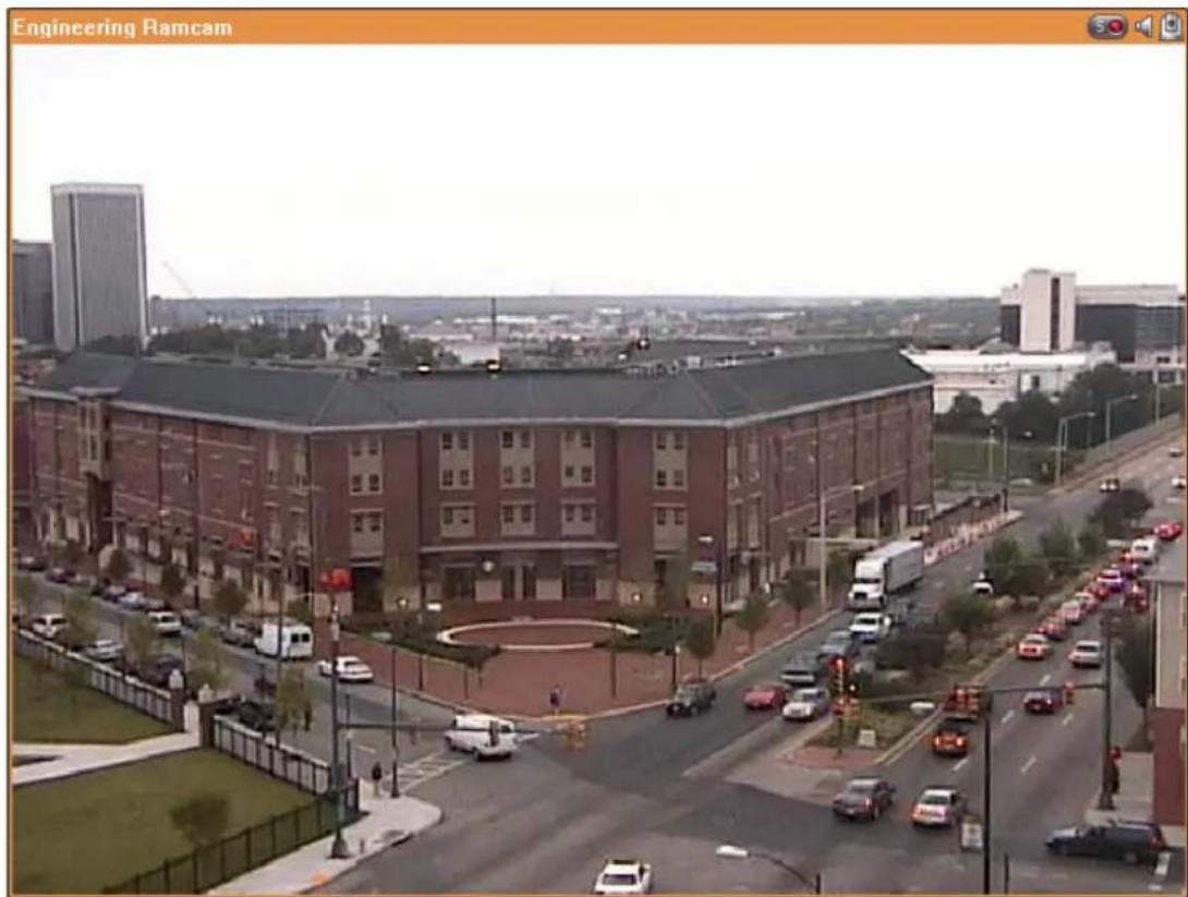
If your camera supports pan and tilt functions, you can click the channel on the screen and adjust the viewing angle with your mouse directly. If zooming is supported, you can scroll the mouse wheel to zoom in or zoom out the video. These functions are available depending on the camera models. Please consult the camera's documentation for details.
Camera Status
The camera status is indicated by the icons shown below:
| Icon | Camera Status |
 | Scheduled or continuous recording is in process |
| [HSDT] | This IP camera supports audio function |
 | This IP camera supports PTZ function |
 | Manual recording is enabled |
 | The recording triggered by advanced event management ("Camera Settings" > "Alarm Settings" > "Advanced Mode") is in process |
| [0087] | The alarm input 1 of the IP camera is triggered |
| [S322] | The alarm input 2 of the IP camera is triggered |
| [CTM6] | The alarm input 3 of the IP camera is triggered |
| [TDH1] | Motion detection recording is in process |
| [6054] | Digital zoom is enabled |
Connection Message
When the NVR fails to display the video of an IP camera, a message will be shown in the channel window to indicate the status.
| Message | Description |
| Connecting If the IP camera is located on remote network or the Internet, it may take some time to establish the connection to the camera. | |
| Disconnected The NVR cannot connect to the IP camera. Please check the network connection of your computer and the availability of the IP camera. If the IP camera is installed on the Internet, make sure you have opened the port on your router or gateway in order to access the IP camera. Please refer to Appendix B. | |
| No Permission You do not have the right to view the channel. Please login as a user with the access right or contact the system administrator. | |
| Server Error Please check the camera settings or update the firmware of the IP camera (if any). Contact the technical support if the error persists. | |
Note:
-
Enabling or disabling manual recording will not affect scheduled or alarm recording tasks. They are independent processes.
-
You can right click the IP camera channel and select the following options:
a. Full screen
b. Keep aspect ratio
c. Deinterlace (available on particular camera models only)
d. Keep original size
3.3 Video Playback
You can play the videos on the NVR by the local display. To use this feature, click

on the monitoring screen. Most of the icons on the playback screen are the same as those on the monitoring screen. Please refer to Chapter 3.2 for the icon description.
Note: You must have the playback access right to the IP cameras to play the videos. You can login VioStor as admin and edit the playback access right in "User Management" by the web-based administration interface.
When the playback screen is shown, select a camera channel on the NVR. Next,
select the date and time of the video, click 📋 to start searching. The videos which matched the search criteria will be played automatically.
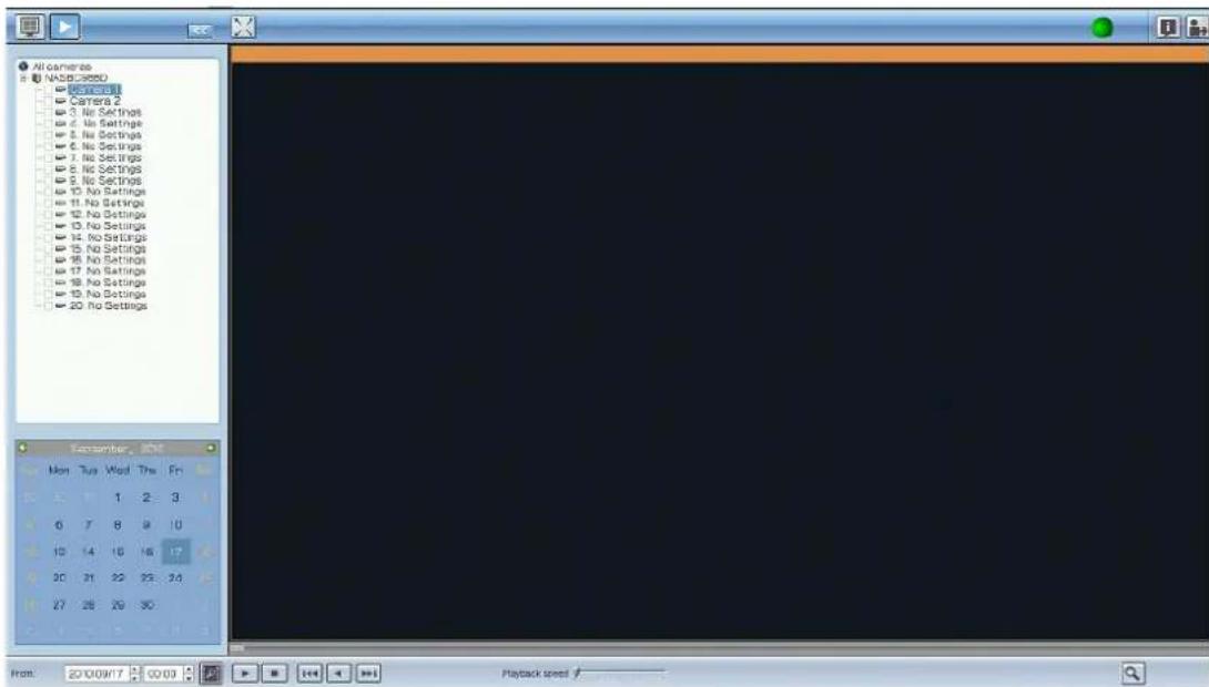
Playback Settings:

You can play, pause, stop, reverse play a video file, or select to play the previous or next file. When playing a video, you can use the scroll bar to adjust the playback
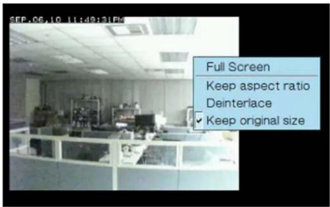
speed or click the digital zoom icon 🔒 to zoom in or zoom out the video. You can also right click the IP camera channel and select the following options:
a. Full screen
b. Keep aspect ratio
c. Deinterlace (available on particular camera models only)
d. Keep original size
Chapter 4. Use VioStor by Web-based Interface
You are recommended to use Microsoft Internet Explorer to monitor the IP cameras and manage the functions of VioStor.
Important Notice:
Before you start to use VioStor, make sure you have installed the hard disks in the server correctly and finished the disk formatting and configuration. Otherwise, the server will not function properly.
4.1 Connect to VioStor
Follow the steps below to access the monitoring page of VioStor.
- Run Finder. Double click the name of VioStor. You can also type the IP address of the server in the IE browser to access the monitoring page.

Double click to login the server
- Enter the user name and password to login VioStor.
Default user name: admin*
Default password: admin
* If you are using the VS-201/VS-101/NVR-104, the login name is "administrator" and the login password is "admin".
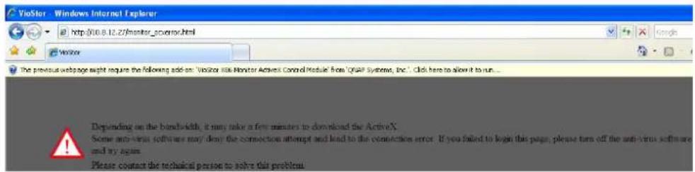
- To view the live video, install the ActiveX add-on.
4.2 Monitoring Page
Upon successful login, the monitoring page will be shown. Select the display language. You can start to configure the system settings and use the monitoring and recording functions of the server.
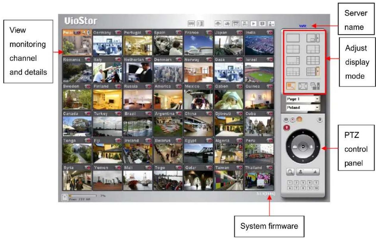
| Icon | Description |
| Multi display mode:VioStor supports multi-display mode. (This function can only be used when the computer or the host is connected to multiple monitors.) | |
| Multi-server monitoring:Up to 120 channels from multiple QNAP NVR servers can be monitored. | |
| Select language:Select the display language. | |
 | E-map:Display the location of the IP camera. The E-map can be changed in system configuration page.System configuration:Login the system administration page (admin access required). |
 | Monitoring settings:Configure the advanced settings of the monitoring page.You can configure the source of the video/audio stream, event notification, and snapshot folder. |
 | Playback:Enter the video playback page. The administrator can grant access right to the users to playback the videos. |
 | Help:View the system online help. |
 | Logout:Logout VioStor. |
 | Snapshot:Take a snapshot on the selected channel. When the picture is shown, right click the picture to save it to the computer. |
 | Manual recording:Enable or disable manual recording on the selected channel. The administrator can enable or disable this option in the system configuration page. |
 | Audio (optional):Turn on/off the audio support for the monitoring page. |
 | Login network camera homepage:Select a channel and click this button to go to the homepage of the selected IP camera. |
 | Event notification:When the alarm recording is enabled and an event is detected, this icon will be shown. Click this icon to view the alert details. |
 | Digital zoom:Select a channel and click this button to enable the digital zoom function. (You can also right click the monitoring channel to enable this function.)Press and hold the left mouse button to zoom in or press and hold the right mouse button to zoom out. You can press the left mouse button to drag the viewing angle of |
| the IP camera.You can also use the mouse wheel or the PTZ control panel to use the digital zoom function. | |
 | Focus control:Adjust the focus control of the PTZ camera. |
 | Select PTZ camera preset positions:You can view different preset positions of the IP camera by clicking the number buttons. To configure the preset positions of the IP camera, please refer to the user manual of the IP camera. |
 | Recording storage status:Display the percentage of the used storage and the free space of VioStor. |
Note:
- Enabling or disabling the manual recording feature will not affect the scheduled or alarm recording.
- By default, the snapshots are saved in "My Documents" or "Documents"> "Snapshots" on your Windows OS.
- If the snapshot time is inconsistent with the actual time that the snapshot is taken, it is caused by the network environment but not a system error.
- Click the event notification icon to view the event details, enable or disable the alert sound or clear the event logs.

- When the digital zoom function is enabled on multiple IP cameras, the zooming function will be affected if your computer performance is not high enough.
- Right click the monitoring channel on the live view page. The following functions are available depending on the IP camera model.
a. Connect to camera homepage.
b. Camera setting: Enter the configuration page of the IP camera.
c. PTZ: Pan/Tilt/Zoom camera control.
d. Preset: Select the preset positions of the PTZ camera.
e. Enable live tracking: Available on Panasonic NS202(A) camera.
f. Disable live tracking: Available on Panasonic NS202(A) camera.
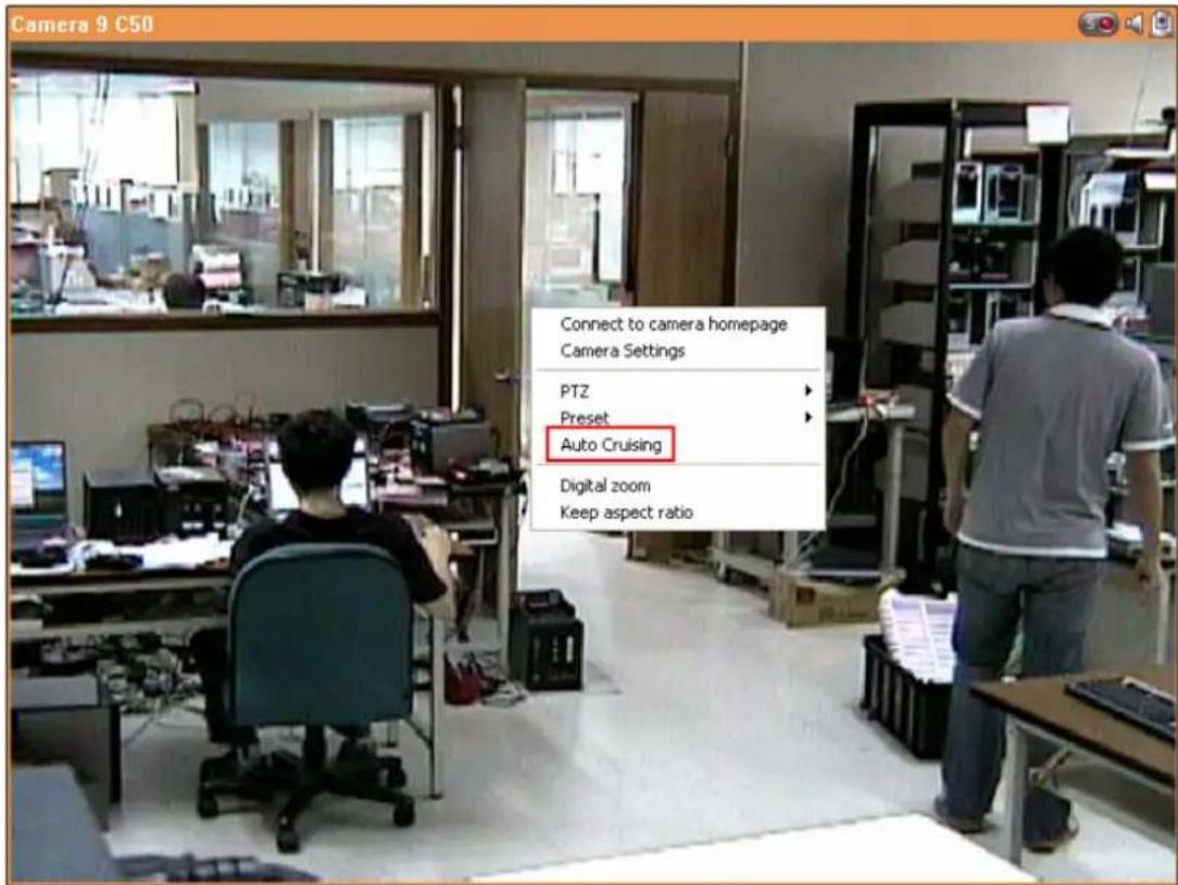
g. Auto cruising: This feature is used to configure the PTZ cameras to cruise according to the preset positions and the staying time set for each preset position.
h. Digital zoom: Enable/disable digital zoom.
i. Keep aspect ratio.
4.2.1 Live Video Window
The live videos of the IP cameras configured on VioStor are shown on the monitoring page. You can click the channel window to use the features supported by the IP camera, e.g. digital zoom or pan/tilt/zoom.

Camera Status
The camera status is indicated by the icons shown below:
| Icon | Camera Status |
| Scheduled or continuous recording is in process |
 | This IP camera supports audio function |
| [12C3] | This IP camera supports PT function |
| Manual recording is enabled |
| [CXV2] | The recording triggered by advanced event management ("Camera Settings" > "Alarm Settings" > "Advanced Mode") is in process |
| [87B4] | The alarm input 1 of the IP camera is triggered and recording is in process |
 | The alarm input 2 of the IP camera is triggered and recording is in process |
| [SKW2] | The alarm input 3 of the IP camera is triggered and recording is in process |
| [08HC] | Motion detection recording is in process |
 | Digital zoom is enabled |
Connection Message
When the NVR fails to display the video of an IP camera, a message will be shown in the channel window to indicate the status.
| Message | Description |
| Connecting If the IP camera is located in remote network or the Internet, it may take some time to establish the connection to the camera. | |
| Disconnected The NVR cannot connect to the IP camera. Please check the network connection of your computer and the availability of the IP camera. If the IP camera is installed on the Internet, make sure you have opened the port on your router or gateway in order to access the IP camera. | |
| No Permission You do not have the right to view the monitoring channel.Please login as a user with the access right or contact the system administrator. | |
| Server Error Please check the camera settings or update the firmware of the IP camera (if any). Contact the technical support if the error persists. | |
4.2.2 Display Mode
VioStor supports different display modes for viewing the monitoring channels.
![graph TD A["Single channel mode"] --> B["Grid Layout"] C["4-channel mode"] --> D["Grid Layout"] E["8-channel mode"] --> F["Grid Layout"] G["10-channel mode"] --> H["Grid Layout"] I["Adjust window size"] --> J["Grid Layout"] K["Picture-in-Picture mode"] --> B L["6-channel mode"] --> D M["9-channel mo…](/content/2026/06/1279227/images/3313fe438150b7d8463f3d4cfb36f550aa8ded05f51c86e090b0dc6a26b79e56.jpg)
4.2.3 PTZ Camera Control Panel
The term "PTZ" stands for "Pan/Tilt/Zoom". If your IP camera supports the PTZ feature, you can use the control panel on VioStor to adjust the viewing angel of the IP camera. These functions are available depending on the camera models.
Please refer to the user manual of the IP cameras for more information. Note that the digital zoom function will be disabled when the PTZ function is in use.

4.2.4 Multi-server Monitoring
Follow the steps below to use the multi-server monitoring feature of VioStor.
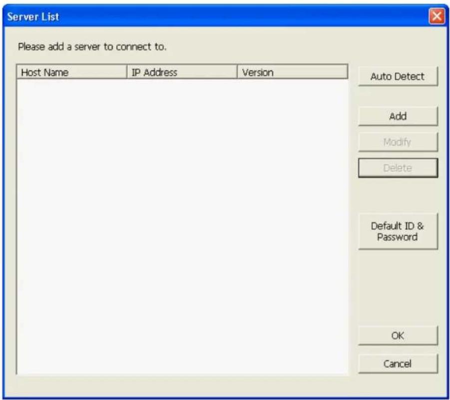
- Click "Server List" on the monitoring page.
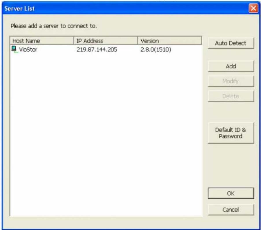
a. Click "Auto Detect" to search for the QNAP NVR on the LAN and add the server to the server list.
b. Click "Add" to add the QNAP NVR to the server list.
- Up to 120 channels from multiple QNAP NVR servers can be added for monitoring.
4.2.5 Monitor Settings
To configure advanced monitor settings, click 📄.

You can configure the following settings:
Video Streaming
Stream from the server: If you cannot connect to the IP camera from your computer, select this option and the NVR will stream the video from the NVR. This option does not require extra port mapping configuration; but may influence the performance of the NVR.
Stream from IP camera: If the NVR and the IP cameras are located on the same LAN, select this option to stream the video from the IP camera. Note that you need to configure the port forwarding settings on the IP cameras if the NVR, IP cameras, and the computer are located behind a router, a virtual server, or a firewall.
Video Windows
a. Highlight the video window when an event is triggered: The video window will flash if an event is triggered.
b. Display the windows without monitoring authority: Select this option to show the channels that the user does not have access right to monitor.
c. Display the windows without configuration: Select this option to show the channels that have not been configured.
Event Notification: When enabled and an event is triggered, the alert icon

will be shown on the monitoring channel instantly. Click the icon to view the alert details.
Display Order: Click "Reset" to reprioritize the monitoring channels to default order.
Browser: Select to show or hide the toolbars of the IE browser.
Snapshot: Specify the location where the snapshots are saved and the image format (JPEG or BMP).
Show timestamp and camera name: Show the time stamp and the camera name on the snapshot.
4.2.6 Auto Cruising
The auto cruising feature of VioStor is used to configure the PTZ cameras to cruise according to the preset positions and the staying time set for each preset position.
To use the auto cruising feature, follow the steps below.
- On the monitoring page of VioStor, click 📄 to go to the configuration page of the PTZ camera.
- Set the preset positions on the PTZ camera.
- Return to the monitoring page of VioStor. Right click the display window of the PTZ camera. Select "Auto Cruising".
- Click the number buttons to view the preset positions of the PTZ camera. When you click the button, the name of the corresponding preset position is shown on the "Preset Name" drop-down menu.
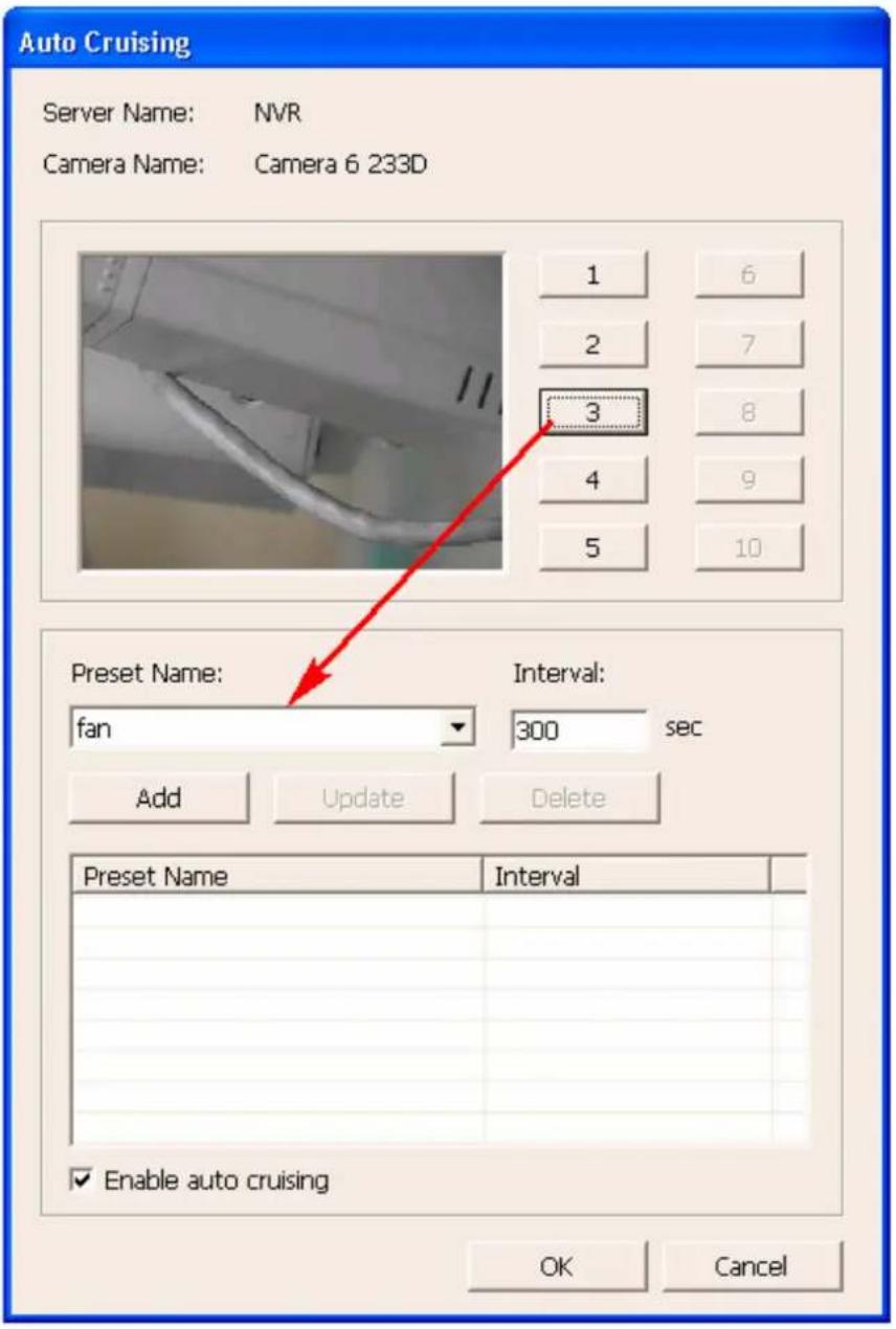
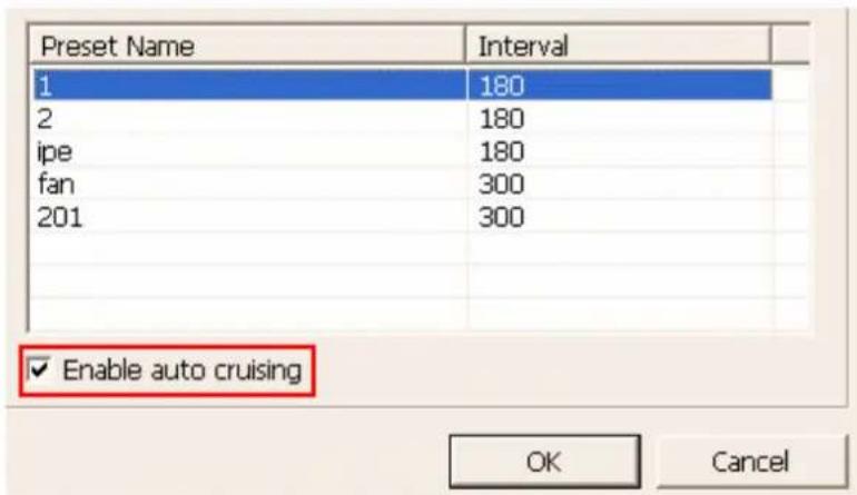
- Add: To add a setting for auto cruising, select the "Preset Name" from the drop-down menu and enter the staying time (interval, in seconds). Click "Add".

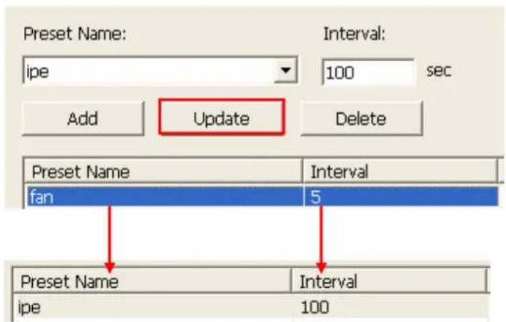
- Update: To change a setting on the list, highlight the selection. Select another preset position from the drop down menu and/or change the staying time (interval). Click "Update".
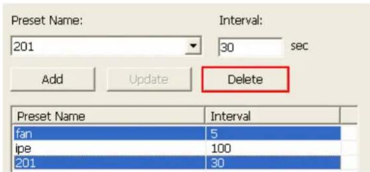
- Delete: To delete a setting, highlight a selection on the list and click "Delete". To delete more than one setting, press and hold the Ctrl key and click the settings. Then click "Delete".
- After configuring the auto cruising settings, check the box "Enable auto cruising" and click "OK". The NVR will start auto cruising according to the settings.
Note:
1) The default staying time (interval) of the preset position is 5 seconds. You can enter 5–999 seconds for this setting.
2) The system supports up to 10 preset positions (the first 10) configured on the PTZ cameras. You can configure up to 20 settings for auto cruising on the NVR. In other words, the NVR supports maximum 10 selections on the drop-down menu and 20 settings on the auto cruising list.
Chapter 5. Playback the Video Files
VioStor provides an intuitive web interface to search and play the recording files without any extra software required. You can access the video files over LAN or WAN.
5.1 Use the Web-based Playback Interface (VioStor Player)
- Click the playback button ▶ on the monitoring page.
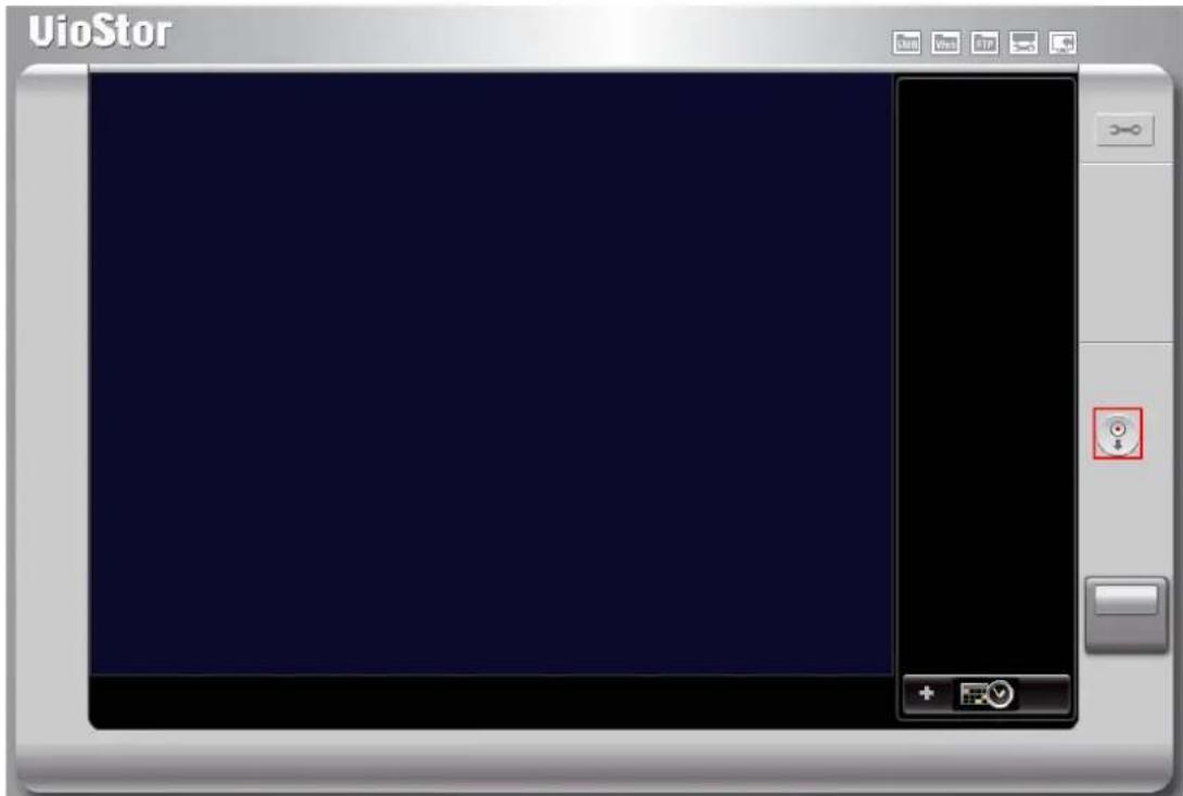
- VioStor Player will be shown. You can use this program to search and play the recording files on the NVR servers. To return to the monitoring page, click
To enter the system administration page, click

Note: You must have the access rights to the IP cameras in order to view and play the recording files by VioStor Player. Please refer to Chapter 6.5 for access right configuration.
5.1.1 Connect to Server for Playback
1. Click "Play by Time"


- The following dialog will be shown.
![Search Recordings by Time Server & Camera Host Name VioStor [10.8.12.155] No. Camera Name 1 Eastman Quad 2 waterbury 3 Bielawa Poland 4 Shinagawa 5 Airport 6 Puako Hawaii US 7 Hotel Forum Rome 8 Woodlands resort 9 Webcamera Add Edit Remove Auto Default Settings Selected Camera Camera Name Text entry…](/content/2026/06/1279227/images/b1e5b99b77937cd1a305def5e44b280105f1375fd9a50aec3cc972a2c202efac.jpg)
- Configure servers:
a. Add: Add a server.
b. Modify: Modify a server.
c. Remove: Remove a server.
d. Auto: Auto-search servers.
e. Default settings: Enter the default user name and password for all newly added servers.
- Select the data search mode.
• Date and time search (Text entry)
i. Select the NVR server(s) and the IP camera(s)*.
ii. Click the "Text entry" tab.
iii. Select the recording type, the start and end time when the video is recorded.
iv. Click "Preview" to preview the searched video.
v. Click "OK".
* You can select 4 IP cameras at maximum.
![Search Recordings by Time Server & Camera Host Name NVR [172.17.26.89] No. Camera Name 3 3.Axis 210 4 4.VCC-9800 PTZ 5 Camera 5 6 6.DCS-5220 A-PT 7 7.ELMO PTC-401C-JP 8 8.FCS-1040 PT 9 Camera 9 10 10.FCS-1010 PT 11 Camera 11 12 12.P6.WD21.PTZ Edit Selected Camera Camera Name NVR: 1.WCS-2060 A-PT NVR…](/content/2026/06/1279227/images/cdf2e030cd872bc010e8402d132c39cbfd406ea6fa8c8c0ec7f1d8cb1dbf0c19.jpg)
- Timeline search
i. Select the NVR server(s) and the IP camera(s)*.
* You can select 4 IP cameras at maximum.
![Search Recordings by Time Server & Camera Host Name VioStor [10.8.12.155] Edit No. Camera Name ✓ 1 Eastman Quad □ 2 SNC-RZ30P □ 3 Bielawa Poland □ 4 Shinagawa □ 5 Airport □ 6 Puako Hawaii US □ 7 Hotel Forum Rome □ 8 Recycle company □ 9 Webcamera □ 10 CNVR Selected Camera Camera Name VioStor: Eastman…](/content/2026/06/1279227/images/0d01609453326cad8a81febc7bdb5daea55377bc74137c34c890286c0d2748fd.jpg)
ii. Click the "Graphical entry" tab.
![Search Recordings by Time Server & Camera Host Name NVR [172.17.26.89] No. Camera Name ✓ 3 3.AXIS 210 ☐ 4 4.VCC-9800 PTZ ☐ 5 Camera 5 ☐ 6 6.DCS-5220 A-PT ☐ 7 7.ELMO PTC-401C-IP ☐ 8 8.FCS-1040 PT ☐ 9 Camera 9 ☐ 10 10.FCS-1010 PT ☐ 11 Camera 11 ☐ 12 12.T6-WD01.PTZ Edit Selected Camera Camera Name NVR:…](/content/2026/06/1279227/images/4ae3df4eb46920fa495750ddb96e1f455c23f3f6fee1cfc2e5512f385b046854.jpg)
iii. Select the recording type.

iv. Specify the time range when the files are recorded. The settings will be applied to all the cameras selected.
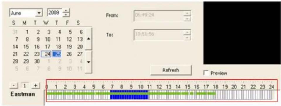
v. Click "Preview" to preview the searched video.

vi. Click "OK".

- Event entry
i. Select the NVR server(s) and the IP camera(s)*.
* You can select 4 IP cameras at maximum.
![Search Recordings by Time Server & Camera Host Name VioStor [10.8.12.155] Edit No. Camera Name ✓ 1 Eastman Quad □ 2 SNC-RZ30P □ 3 Bielawa Poland □ 4 Shinagawa □ 5 Airport □ 6 Puako Hawaii US □ 7 Hotel Forum Rome □ 8 Recycle company □ 9 Webcamera □ 10 QUAD Selected Camera Camera Name VioStor: Eastman…](/content/2026/06/1279227/images/6f65c70d3ce145e33fb98c623adf9ed08725c735669936fbd6d5ea3d0a108cde.jpg)
ii. Click the "Event entry" tab.
![Search Recordings by Time Server & Camera Host Name VioStor [10.8.12.155] No. Camera Name 1 Eastman Quad 2 SNC-RZ30P 3 Bielawa Poland 4 Shinagawa 5 Airport 6 Pukko Hawaii US 7 Hotel Forum Rome 8 Recycle company 9 Webcam 10 GPS Selected Camera Camera Name VioStor: Eastman Quad Edit Text entry | Graph…](/content/2026/06/1279227/images/23acf014c3f2b073ada500f4d21ead9a334b5fd794acadac985309dc4fd24a83.jpg)
iii. Select the event type.

iv. Specify the time range when the files are recorded.

v. Specify the number of minutes to play the video recorded before and after the event.

vi. Event search. This function is provided for you to search for all the events occurred on the IP cameras. You may refer to the event details to search for the recording data.
√ Search all: Search for the specified events occurred on all the IP cameras of an NVR within the time range specified.
√ Search: Search for the specified events occurred on one IP camera within the time range specified.

vii. The events will be shown. Click "OK".

- When the files are shown, you can play the video.
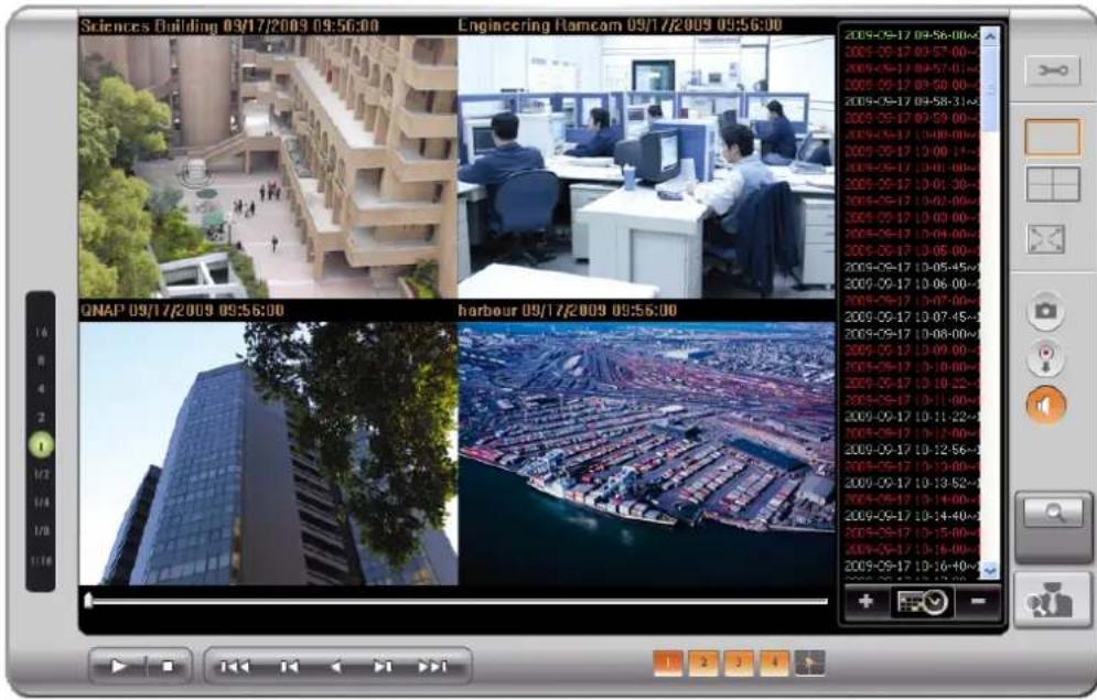
Note: The regular recordings are shown in white while the alarm recordings are shown in red on the playlist.
5.1.2 Play Video Files from Your Computer
1. C lick "Add files"


2. Browse and select the files.
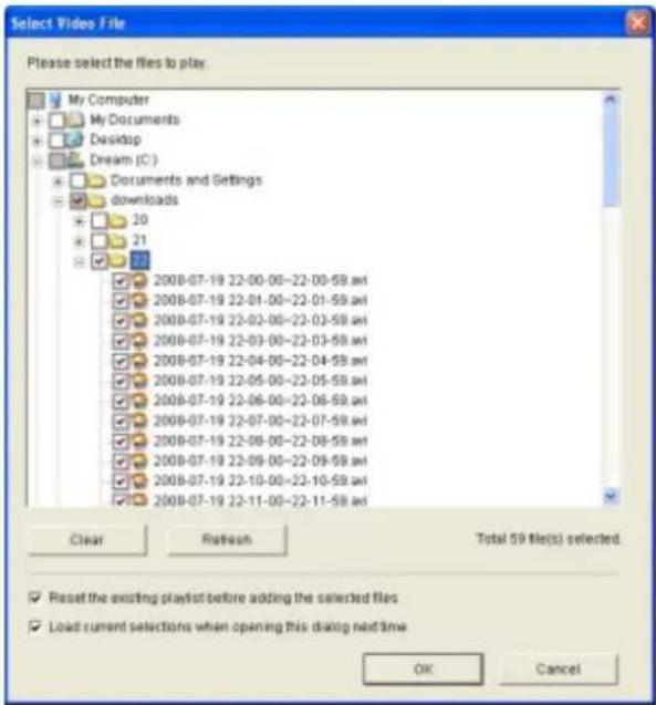
3. The playlist will be shown. Click "Play"

to start playing.
5.1.3 Quad-view Playback
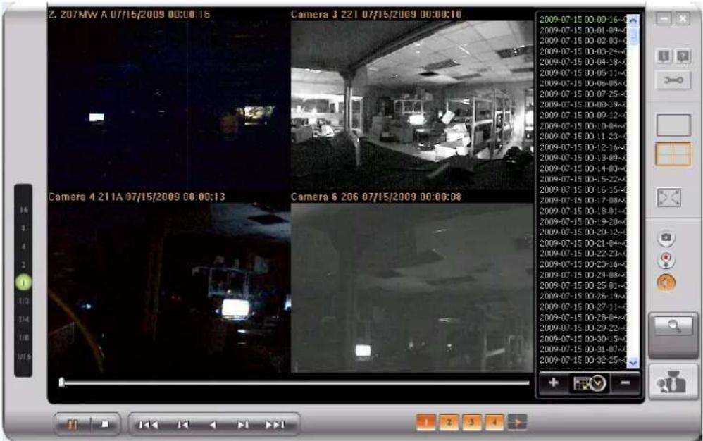
The quad-view playback feature allows you to search for the video recorded by the NVR servers quickly. You can view the videos of four IP cameras simultaneously or select to divide the video of one IP camera into four time periods and play them in a quad-view window.
√ Divide the selected time equally into four playback windows
Select only one camera. Click "Text entry" or "Graphical entry". Enter the search criteria and check the option "Divide the selected time period equally into all the playback windows to play". Click "OK".
![Search Recordings by Time Server & Camera Host Name 34-VS-5012A [172.17.27.34] No. Camera Name 1 ??? 1. 225FD 2 2. 207MW A 3 Camera 3 221 4 Camera 4 211A 5 Camera 5 6 Camera 6 206 7 Camera 7 HCM-311 8 Camera 8 9 Camera 9 C50 10 Camera 10 Selected Camera Camera Name 34-VS-5012A: 2. 207MW A Edit Text…](/content/2026/06/1279227/images/b28cf5772c312cd161c659a2bd9290800a6002538f41cf1f6c3612ddfe76ffe3.jpg)
√ Play the video of four IP cameras
Select four IP cameras. Enter the search criteria in the "Text entry" or "Graphical entry". When the search results are shown, you can play the video files of the four IP cameras simultaneously.
![Search Recordings by Time Server & Camera Host Name 34-VS-5012A [172.17.27.34] Edit No. Camera Name ✓ 2 2.207MW A ✓ 3 Camera 3 221 ✓ 4 Camera 4 211A □ 5 Camera 5 ✓ 6 Camera 6 206 □ 7 Camera 7 HCM-311 □ 8 Camera 8 □ 9 Camera 9 C50 □ 10 Camera 10 □ 11 Camera 11 Selected Camera Camera Name 34-VS-5012A:…](/content/2026/06/1279227/images/0523bd1b668b7454a6dd58b8c067b66c56b9e74c7cd60f0152382e7dc16ab283.jpg)
5.1.4 Intelligent Video Analytics (IVA)
The NVR supports intelligent video analytics to allow the users to search the video files efficiently.
The following features are supported for video analytics:
√ Motion detection: Detects the movement of the objects in the video.
√ Foreign object: Detects the new object in the video.
√ Missing object: Detects the missing object in the video.
√ Out of focus: Detects out of focus of the camera in the video.
√ Camera occlusion: Detects if the IP camera is obstructed.
To use this function, follow the steps below:
- Go to the Playback page of the NVR. Add the files to the playlist.
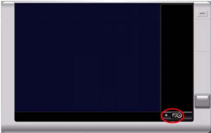
Note: The intelligent video analytics support video search on one channel only.
- On the playback window, click


Note:
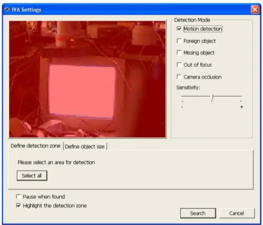
√ When you check the option "Pause when found", the data search stops when a video file which matches the search criteria is found.
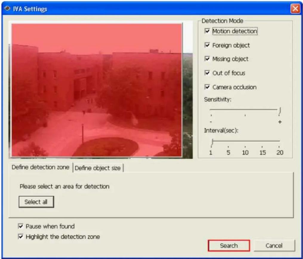
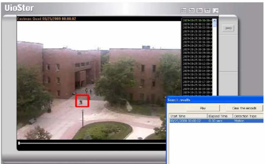
√ When you enable "Highlight the detection zone", the moving objects will be highlighted in red brackets; the foreign or missing objects will be highlighted in yellow brackets; the video which is out of focus or obstructed will be displayed in transparent red.
- Select the detection mode: motion detection, foreign object, missing object, out of focus, or camera occlusion. You can select multiple options.

- Adjust the sensitivity for object detection.

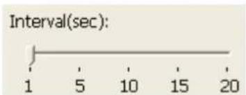
- Adjust the time interval for detecting the foreign objects and missing objects. If a foreign object appears or a missing object disappears for a time period which is longer than the time interval, the NVR will record an event.
Note: The interval slide bar appears only when the options "foreign object" or "missing object" is checked.
- Define the detection zone. Mouse over the edge of the red zone and use the mouse to define the detection zone. Click "Select all" to highlight the entire area for detection.

- Define the object size for the detection. You can use the mouse the drag the yellow zone to define the minimum object size for detection.
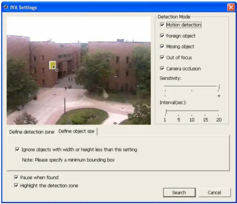
Note: After enabling this option, all the objects smaller than the yellow zone will be ignored for detection.
- Click "Search" to start searching the video by IVA. The results will be shown.
Note:
- You can double click an entry on the search result dialog to play the video. The player will play the video starting from 15 seconds before the event to 15 seconds after the event.
- You can also right click an entry on the search result dialog to export the video and save it on your computer. The exported video starts from 15 seconds before the event to 15 seconds after the event.
5.1.5 Convert to AVI File
You can save the recording files recorded by VioStor as AVI files to your PC.
Note: You must have the playback authority of the IP camera to use this feature.
Follow the steps below to save the video from VioStor.
- Click "Convert to AVI file".

- The following screen will be shown.
![Server & Camera Host Name 26159-VS-5020 [172.17.27.62] Edit No. Camera Name 1 1.Sanyo HD5400 2 2.Sanyo HD5600 3 3.Sanyo HD2300 4 4.Sanyo HD4600 5 5.Sanyo HD2500 6 6.Sanyo HD3300 7 7.Sanyo HD2100 8 Camera 8 9 Camera 9 Text entry Recording Type: Search all recording data From: 12/07/2010 00:00 To: 12/…](/content/2026/06/1279227/images/f95c2632f33fd00905ee7c27121f681bf59e34822677dc4f2c684bd0ad1e9498.jpg)
- Select the NVR server and IP camera.
![Server & Camera Host Name 26159-VS-5020 [172.17.27.62] Edit No. Camera Name 1 1.Sanyo HD5400 2 2.Sanyo HD5600 3 3.Sanyo HD2300 4 4.Sanyo HD4600 5 5.Sanyo HD2500 6 6.Sanyo HD3300 7 7.Sanyo HD2100 8 Camera 8 9 Camera 9](/content/2026/06/1279227/images/c41284c2ef734ee968986157be329779ae06f784fa36b3326d10145f96fa28eb.jpg)
- Enter the recording type.

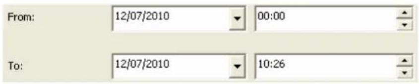
- Specify the time range for the search.
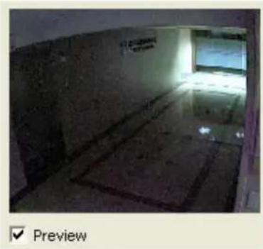
- Click "Preview" to preview the searched video.
- Click "OK". Enter the file name and specify the location where the file is saved to.

- The file will be converted to AVI format.
5.2 Digital Watermarking
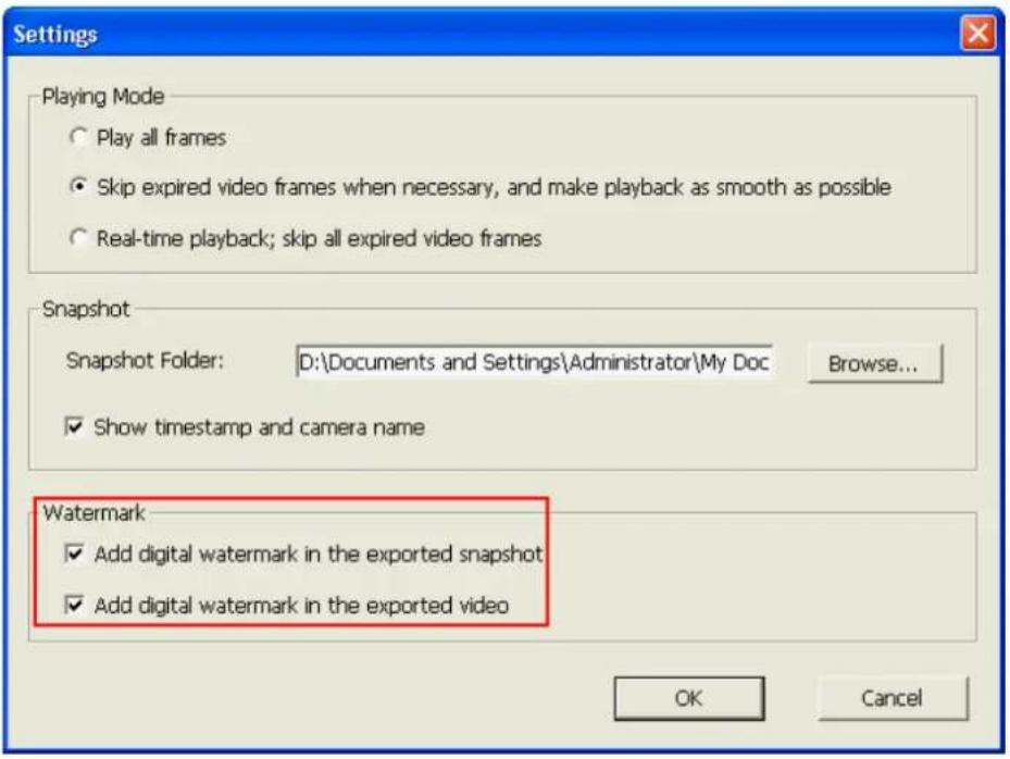
VioStor NVR supports digital watermarking to protect the videos and snapshots from unauthorized modification. You can select to add the digital watermark on the exported video and snapshot on VioStor Player. A permanent digital signal will be added to the exported files which are selected for digital watermarking. The watermark cannot be removed and is only visible by using the watermark proof software.
5.2.1 Export Files with Digital Watermark
To use the digital watermarking feature by VioStor Player, follow the steps below.
-
Click "Playback" to open VioStor Player.
-
Click "Settings"

- Select to add digital watermark in the exported snapshot or video.
- Select the recording files (refer to Chapter 5).
- Click to convert the video files into AVI format.

- Click to start playing and exporting the files.
Note: When you click to the playback mode.

again, the NVR will stop exporting the files and resume
5.2.2 Watermark Proof
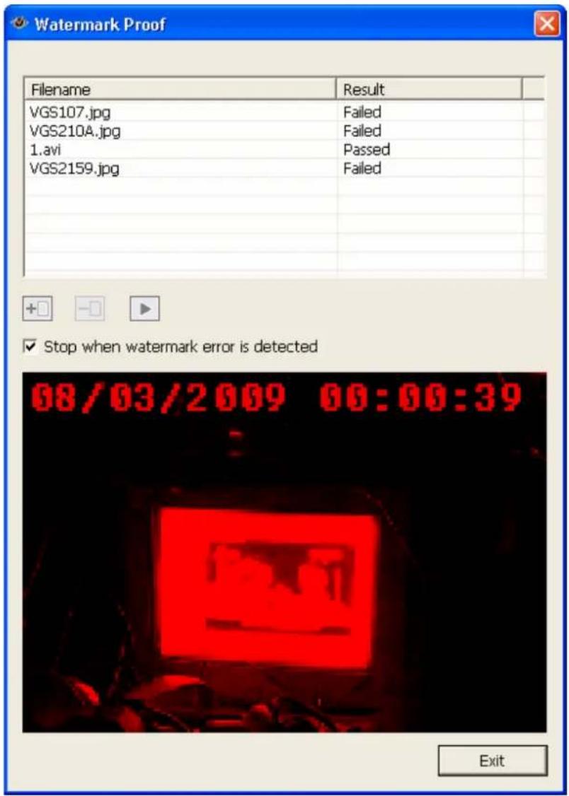
The Watermark Proof utility is installed automatically along with VioStor Player. From the Windows Start menu, select "All Programs" > "QNAP" > "Player" to locate "Watermark Proof".
Run Watermark Proof. The following window will be shown.

Click to browse and locate the files. You can select more than one file at one time.
Click to start checking the files. The Watermark Proof will start checking the files and show the proof result. If you check the option "Stop when watermark error is detected", the checking procedure will stop if a failed file is detected. Otherwise the program will check all the files you have selected. If a file has been modified, the proof result will be shown as "Failed".
5.3 Access the Recording Data
You can access the recording data on VioStor by the following network services:
● Windows Network Neighbourhood (SMB/CIFS)
- Web File Manager (HTTP)
- FTP Server (FTP)

Note:
- To access the video file by these protocols, you must enter the user name and password with the administrator access right.
- To be able to use these services, enable the files services in "Network Settings" > "File Services" in the system administration page.

5.3.1 Windows Network Neighbourhood (SMB/CIFS)
You can access the video files by the SMB/CIFS protocol, which is popularly used on the Windows OS. You can access the folder to where the video files are saved by:
- On the web-based playback interface, click "SMB".
- Run \VioStorIP\ from the Start menu on the Windows OS. For example, if your VioStor IP is 172.17.26.154, enter \172.17.26.154.

5.3.2 Web File Manager (HTTP)
To access the recording data on the NVR from the web browser, click "Web" on the web-based playback interface and login as an administrator.

5.3.3 FTP Server (FTP)
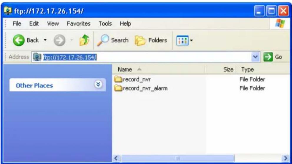
You can access the recording data by FTP:
- On the web-based playback interface, click "FTP".
- In Windows Internet Explorer, enter ftp://username:password@VioStorIP/. For example, enter ftp://admin:admin@172.17.26.154/ if the IP address of your VioStor is 172.17.26.154.
Chapter 6. System Administration
To login the system configuration page of VioStor, click 📄 on the monitoring page and login as an administrator.
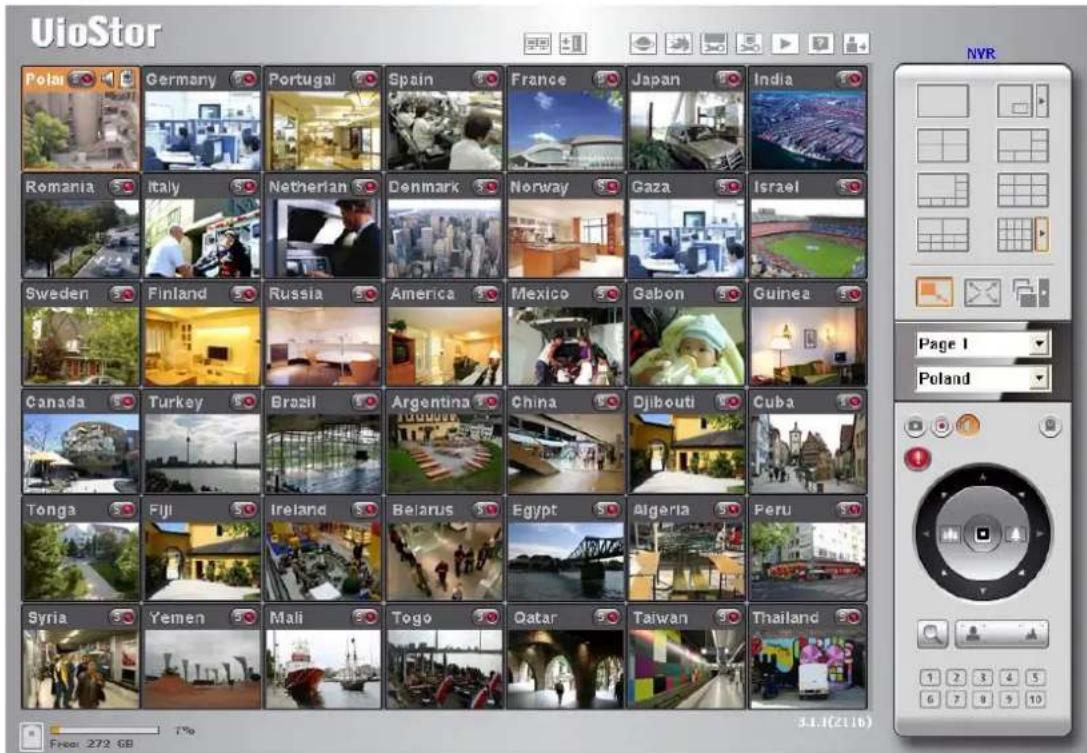
Upon successful login, you can view the monitoring channels, the connection and recording status, and the network bandwidth of the NVR on the "Advanced Mode" page.
| Preview | Camera Name | IP Address | Status | Recording status | Frame rate | Bit rate | Management |
| 1 | Panasonic HCM-481 | 172.17.27.134 | Connected | Recording | 10 fps | 944.4 Kbps | |
| 2 | Axis Q7401 | 172.17.26.65 | Connected | Recording | 16 fps | 435.9 Kbps | |
| 3 | Axis P3301 | 172.17.26.102 | Connected | Recording | 1 fps | 122.7 Kbps | |
| 4 | I-Pro NS202 | 172.17.26.28 | Connected | Recording | 1 fps | 232.9 Kbps | |
| 5 | IQeye 040S | 172.17.27.24 | Connected | Recording | 13 fps | 3606.8 Kbps | |
| 6 | IQeye 041S | 172.17.27.25 | Connected | Recording | 2 fps | 1795.5 Kbps |
You can also select the "Traditional Mode" to view the settings of the NVR.

If the NVR is has not been configured yet, the Quick Configuration page will be shown to guide you through the system setup.
The functions of the buttons on the configuration page are described below:
 | Return to the monitoring page |
 | Playback the videos |
 | View the on-line help |
 | Log out the NVR |
6.1 Quick Configuration
Please follow the instructions to configure VioStor.
Note: All the changes will be effective only after you click "Start installation" in the last step.
Step 1. Enter the server name. The server name supports up to 14 characters which my include alphabets (A-Z and a-z), numbers (0-9), and dash (-). Space and period (.) are not allowed.
- Step 1/6: Enter the name for this server.
Server Name :

Tip: You have to create a unique name for your server in order to identify your server quickly. The server name supports up to 14 characters which may include alphabets (A-Z and a-z), numbers (0-9) and dash (-). Space and period (.) are not allowed.

Step 2. Change the administrator password or select to use the default password (admin).
- Step 2/6: Change the administrator password.
Password :
Verify Password :
Use the original password
Note: If you select "Use the original password", the administrator password will not be changed.
Step 3. Enter the date, time, and time zone of the server.
- Step 3/6: Enter the date, time and time zone for this server.

Tip: This system can be used by the network cameras or other servers as an NTP server by default. To ensure that the date and time of the network cameras is synchronized with this server, please set up all the network cameras by entering the IP address of this server as their NTP server.

Step 4. Enter the IP address, subnet mask and default gateway of the server.
- Step 4/6: Enter the IP address, subnet mask and default gateway for this server.
Obtain TCP/IP settings automatically via DHCP
○ Use the following settings
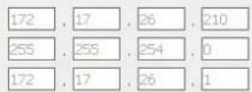
IP Address:
Subnet Mask:
Default Gateway:
Primary DNS Server
Secondary DNS Server
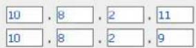
Note: To allow this server to use host names for NTP or SMTP servers, you must provide the IP address of the primary DNS server.

Step 5. Select the disk configuration. All the disk data will be cleared unless you select not to set the disk configuration.
Step 5/6: Select the disk configuration.
Note: The hard drive(s) has (have) been initialized. Select "Do not set disk configuration" or the drive data will be cleared.
Please select the disk configuration for the initialization.
Disk configuration: Do not set disk configuration ▼ Total available storage capacity: 0 GB
The hard drive(s) detected by NVR:
| Disk | Model | Capacity |
| Drive 1 | WDC WD7500AACS-00D6B01.0 | 698.64 GB |
| Drive 2 | WDC WD7500AACS-00D6B01.0 | 698.64 GB |
| Drive 3 | WDC WD7500AACS-00D6B01.0 | 698.64 GB |
| Drive 4 | WDC WD7500AACS-00D6B01.0 | 698.64 GB |
Tip: All settings will be effective after confirming the changes in the last step.


Step 6. Initialize the IP camera settings.
Select the camera model; enter the camera name and IP address of the camera, and the user name and password to login the camera. You can also enable or disable the recording on each channel, test the connection to the IP cameras and then click "Save" to apply the changes.
Click "Search" to search for the IP cameras on the local network. Select a channel and click "Add" to add the camera. By using the search function, the camera model and the IP address are filled in automatically. Click "Close" to close the search results.
- Step 6/6: Initialize IP camera setting.
| 1: 1.WCS-2060 A-PT 172.17.27.133 |
| 2: 2.FCS-0010-送修 172.17.26.21 |
| 3: 3.Axis 210 172.17.26.18 |
| 4: 4.VCC-9800 PTZ 172.17.27.58 |
| 5: Camera 5 |
| 6: 6.DCS-5220 A-PT 172.17.27.129 |
| 7: 7.ELMO PTC-401C-IP 172.17.27.147 |
| 8: 8.FCS-1040 PT 172.17.27.140 |
| 9: Camera 9 |
| 10: 10.FCS-1010 PT 172.17.26.142 |
| 11: Camera 11 |
| 12: 12.IK-WB21 PTZ 172.17.27.21 |
| 13: 13.Sony DS10 172.17.27.68 |
| 14: 14.WCS-0020 PT 172.17.26.126 |
| 15: 15.PT-7135 A-PT 172.17.27.110 |
| 16: 16.IP-7134 A 172.17.27.218 |
| Camera Brand: | LevelOne |
| Camera Model: | LevelOne FCS-1060/WCS-2060 |
| Camera Name: | 1.WCS-2060 A-PT |
| IP Address: | 172.17.27.133 |
| Port | 80 |
| User Name: | root |
| Password: | ●●●●● |
Enable recording on this camera

Note: Please enter the settings of the connected network camera, and click Save to add it one by one. You can click Test to verify the settings you entered.

After completing the settings, click "Start Installation" to apply the changes and initialize the system.
- Finish
The changes you have made to the server are as below. Click "Start installation" to begin the quick configuration; or click "Back" to return to the previous steps to modify the settings.
| Server Name : | NVR |
| Password: | The password is unchanged. |
| Time Zone : | (GMT+08:00) Taipei |
| Time Setting: | 2009/6/30 16:20:44 |
| Network : | Obtain TCP/IP settings automatically via DHCP |
| Primary DNS Server | 10.8.2.11 |
| Secondary DNS Server | 10.8.2.9 |
| IP Camera : | You have configured 13 camera(s) |
| Disk configuration: | Do not set disk configuration |
| Drive 1: | WDC WD7500AACS-00D6B01.0 698.64 GB |
| Drive 2: | WDC WD7500AACS-00D6B01.0 698.64 GB |
| Drive 3: | WDC WD7500AACS-00D6B01.0 698.64 GB |
| Drive 4: | WDC WD7500AACS-00D6B01.0 698.64 GB |

The quick configuration is completed and you can start to use VioStor. Click "Start Monitoring" to view the live video from the IP cameras or click "Close" to return to the system administration home page.
System is initializing, please wait.
The system is being configured, do NOT power off the server or unplug the hard drive(s).
- Enter the server name.
- Change the administrator password.
- Enter the date, time and time zone for this server.
- Enter the IP address, subnet mask and default gateway for this server.
- Initialize the disk volume on this server.
- Add the IP cameras to be recorded to this server.

System configuration completed.

Congratulations! You have successfully configured the system. Please click "Close" to return to the home page or "Start Monitoring" to enter the monitoring page.
6.2 System Settings
You can configure the basic system settings including the server name, the date & time, and view the system settings.
6.2.1 Server Name
Enter the name of VioStor. The server name supports maximum 14 characters, which can be a combination of alphabets, numbers, and hyphen (-). It does not allow spaces ( ), pure numbers, or the following characters:
. ; : " < > * + = \ | ? , [ ] /

6.2.2 Date & Time
Set the date, time, and time zone according to your location. If the settings are incorrect, the following problems may occur:
- When playing the video files, the display time will be incorrect.
- The display time of the event log will be inconsistent with the actual time when the event was recorded.
- Adjust the date, time and time zone of this server
Time Zone:
(GMT+08:00) Taipei

Date: / Time:
2009/6/19


Synchronize with an Internet time server automatically
Server:
pool.ntp.org
Update now
(Status:--)
☐ Set the server time the same as your computer time.
Note:
- This system can be used by the network cameras or other servers as an NTP server by default.
To ensure that the date and time of the network cameras is synchronized with this server, please set up all the network cameras by entering the IP address of this server as their NTP server. - To access NTP servers by host names, you must configure primary DNS server in the network settings.
- If the time settings are changed, recording will stop to apply the changes (maximum 3 minutes).
- Apply
Synchronize with an Internet time server automatically
You can enable this option to update the date and time of the NVR automatically with an NTP (Network Time Protocol) server. Enter the IP address or the domain name of the NTP server, for example, time.nist.gov or time.windows.com. Then enter the time interval for adjusting the time.
The NVR can be configured as the NTP server for the IP cameras or other servers. To ensure the date and time of the IP cameras are synchronized with the NVR, enter the IP address of VioStor as the NTP server of the IP cameras.
Note: It may take several minutes to synchronize the time after you enable the NTP server feature.
6.2.3 View System Settings
You can view the system settings such as the server name on this page.
| - View System Settings | |
| Server Name | |
| Server Name | NVR |
| Date & Time | |
| Date | June 30, 2009 |
| Time | 04:21:20 PM |
| Time Zone | (GMT+08:00) Taipei |
| NTP Server | -- |
| NTP Sync Interval | -- |
| System Information | |
| Version | 3.0.0 Build 1824 |
6.3 Network Settings
You can configure the WAN and LAN settings, DDNS service, file service, host access control, protocol management and view the network settings in this section.
6.3.1 TCP/IP Configuration
Select one of the following options to configure the TCP/IP settings of the NVR.
- Obtain IP address settings automatically via DHCP
Select this option to allow the NVR to acquire an IP address on the local network automatically if a DHCP server is available.
- Use static IP address
To assign a fixed IP to the NVR, enter the IP address, the subnet mask, and the default gateway.
Primary DNS Server: Enter the IP address of the primary DNS server that provides the DNS service for the NVR on the external network.
Secondary DNS Server: Enter the IP address of the secondary DNS server that provides the DNS service for the NVR on the external network.
Note: The Jumbo Frame setting is valid in Gigabit network environment only. All the network appliances connected must enable Jumbo Frame and use the same MTU value.
If your NVR supports two LAN ports, you can select to use failover, load balancing, or standalone settings. To use these features, make sure both LAN ports are connected to the network.

Configuration of Network Interfaces
● Failover (Default settings for dual LAN NVR models)
Failover refers to the capability of switching over the network transfer port to the redundant port automatically when the primary one fails due to hardware or connection error to avoid network disconnection. When the primary network port resumes the connection, the network transfer will be switched over to that port automatically.
Failover
Network transfer rate
1000Mbps full-duplex
Obtain IP address settings automatically via DHCP
○ Use static IP address
Fixed IP Address
Subnet Mask
Default Gateway
172.17.21.59
- 255 . 254 . 0
172.17.20.1
Primary DNS Server
Secondary DNS Server
10 . 8 . 2 . 9
10 . 8 . 2 . 11
Enable DHCP Server
Start IP Address
End IP Address
Lease Time
169 . 254 . 1 . 100
169 . 254 . 1 . 200
1 Day(s) 0 Hour(s)
- Load balancing
Load balancing enables the network resources to spread between two or more network interfaces to optimize the network transfer and enhance the system performance. It operates on layer 3 protocol (IP, NCP IPX) only.
Multicast/broadcast and other non-routable protocols such as NetBEUI can only be transferred via the main network port.
Note: To optimize the network transfer speed of VioStor in load balancing mode, please use a managed Ethernet switch and enable 802.3ad (or link aggregation) on the ports of the switch that the Giga LAN ports of VioStor are connected to.
Load balancing
Network transfer rate
1000Mbps full-duplex
Obtain IP address settings automatically via DHCP
○ Use static IP address
Fixed IP Address
Subnet Mask
Default Gateway
172 . 17 . 21 . 59
- 255 . 254 . 0
172 . 17 . 20 . 1
Primary DNS Server
Secondary DNS Server
10 . 8 . 2 . 9
10 . 8 . 2 . 11
Enable DHCP Server
Start IP Address
End IP Address
Lease Time
169 . 254 . 1 . 100
169 . 254 . 1 . 200
1 Day(s) 0 Hour(s)
- Standalone
The standalone option allows you to assign different IP settings for each network port. VioStor can be accessed by different workgroups on two different subnets. When load balancing is enabled, failover does not work. You can only enable the DHCP server for the primary network port (LAN 1).
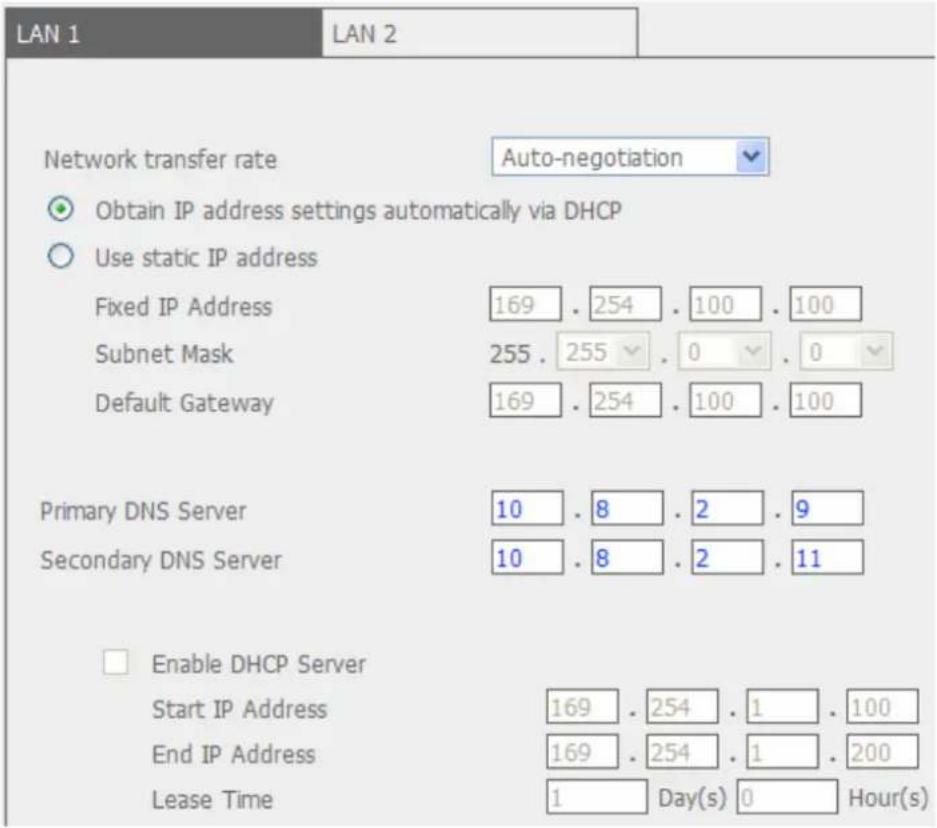
● Network Transfer Rate
You can select auto-negotiation (default), 1000 Mbps, or 100 Mbps. It is recommended to use the default setting that the server will determine the network speed automatically.
- Obtain IP address settings automatically via DHCP
If your network supports DHCP, VioStor will use the DHCP protocol to retrieve the IP address and the related information automatically.
- Use static IP address
To assign a fixed IP to the NVR, enter the IP address, subnet mask, and default gateway.
• Primary DNS Server
Enter the IP address of the primary DNS server that provides the DNS service for VioStor on the external network.
• Secondary DNS Server
Enter the IP address of the secondary DNS server that provides the DNS service for VioStor on the external network.
Enable DHCP Server
If no DHCP server is available on the LAN where VioStor locates, you can enable VioStor as a DHCP server to allocate dynamic IP address to the DHCP clients on the LAN.
You can set the range of the IP addresses allocated by the DHCP server and the lease time. The lease time refers to the time that the IP address is leased to the clients by the DHCP server. When the time expires, the client has to acquire an IP address again.
Note: If there is an existing DHCP server on the LAN, do not enable this function. Otherwise, there will be IP address allocation failure and network access error.
6.3.2 DDNS (Dynamic Domain Name) Service
The DDNS service enables the users to connect to VioStor by the domain name directly. There is no need to memorize the lengthy IP address of the server. To enable the DDNS service, you have to register a DDNS account from a DDNS provider. Please refer to Appendix A
VioStor currently supports the DDNS service provided by:
- DynDNS (http://www.dyndns.org/)
- http://ods.org/
- http://www.dhs.org/
- http://www.dyns.cx/
- http://www.3322.org/
- http://www.no-ip.com/
- http://ipcam.jp/

6.3.3 File Services
You can enable the SMB/CIFS file service, Web File Manager and FTP service to access the video files. These settings are enabled by default.
If your VioStor is installed behind the router, you may enable FTP port mapping to allow the users from the external network to access VioStor via FTP (please refer to Appendix B).
Passive FTP Port Range
You can use the default port range (55536–56559) or define a port range larger than 1023. When using this function, make sure you have opened the configured the port range on your router or firewall.
Respond with external IP address for passive FTP connection request
When passive FTP connection is in use and VioStor is configured behind a router, you can enable this function to allow connection to the NVR over WAN. By enabling this function, the FTP service replies the manually specified IP address or automatically detects the external IP address so that the remote computer can connect to VioStor successfully.
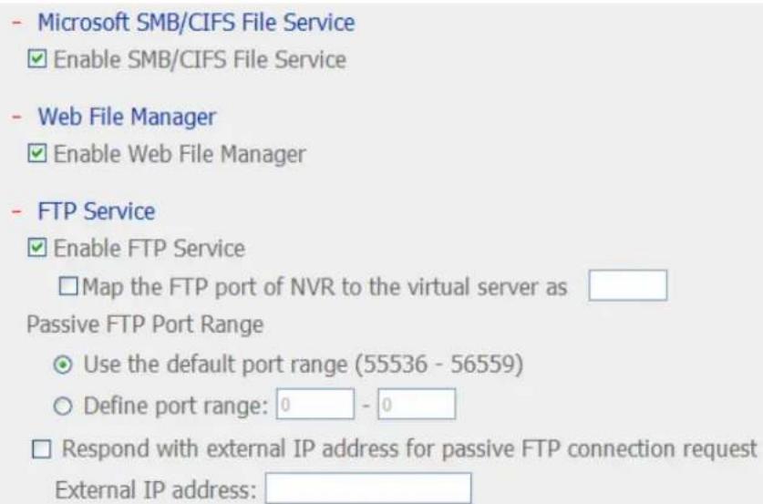
Note: Only users with administration authority can use these file services and the files on the share folder can be read only.

6.3.4 Host Access Control
Specify the connections to be allowed or denied to access VioStor. Choose one of the following options to restrict the access from a network or an IP address (host) to the server:

1. Allow all connections (Default setting)
Allow the connection from all the hosts to the server.
2. Allow connections from the list only
Allow the connection from the hosts specified on the list only.
Note: When this function is enabled, you can only use PC that the IP address is listed on the connection list to connect or find VioStor. The IP address not included in the list will not be able to detect VioStor not listed in allowed connections.
3. Deny connections from the list
Deny the connection from the hosts specified on the list.
Note: Make sure your PC is added to the allowed list in order to connect to the NVR. Otherwise, your PC will always be disconnected from the NVR.
6.3.5 Protocol Management
To assign a particular port to access VioStor by the web browser, enable the option "Specify HTTP port number" and enter the port number. The default setting is 80.
RTP (Real-time Transfer Protocol) is a standardized packet format for delivering real-time audio and video data of the IP cameras over the Internet. The real-time data transfer is monitored and controlled by RTP (also RTCP). The default setting is 6100–6299. If your IP cameras use different RTP ports, enable "Specify RTP port range" and enter the port numbers.
Note: Make sure you have opened the ports configured on the router or firewall to ensure normal monitoring and recording.

6.3.6 View Network Settings
You can view the current network settings and the status of VioStor in this section.
Network Configuration
| Configuration of Network Interfaces | Failover |
| Network Speed | Auto-negotiation |
| Connection Type | Static |
| IP Address | 10.8.12.48 |
| Subnet Mask | 255.255.254.0 |
| Default Gateway | 10.8.12.1 |
| Primary DNS Server | 10.8.2.11 |
| Secondary DNS Server | 0.0.0.0 |
| MAC Address | 00:10:18:00:00:00 |
| Connection Status | 100 Mbps, LAN1:Down, LAN2:Up |
| DDNS Service | disabled |
| DDNS Server | -- |
| DDNS Host Name | -- |
| SMB/CIFS Service | On |
| Web File Manager | On |
| FTP Service | On |
| FTP Port | 21 |
| Host Access Control | Off |
- Close
6.4 Device Configuration
You can configure the SATA disk, RAID management tool, USB disk, and the UPS settings in this section.
6.4.1 SATA Disk
This page shows the model, size and current status of the hard disk drive(s) installed on VioStor. You can format the HDD and check the status, and scan the bad blocks. When the HDD are formatted, VioStor will create the following default share folders:
- record_nvr: The folder to where the regular recording files are saved.
- record_nvr_alarm: The folder to where the alarm recording files are saved.
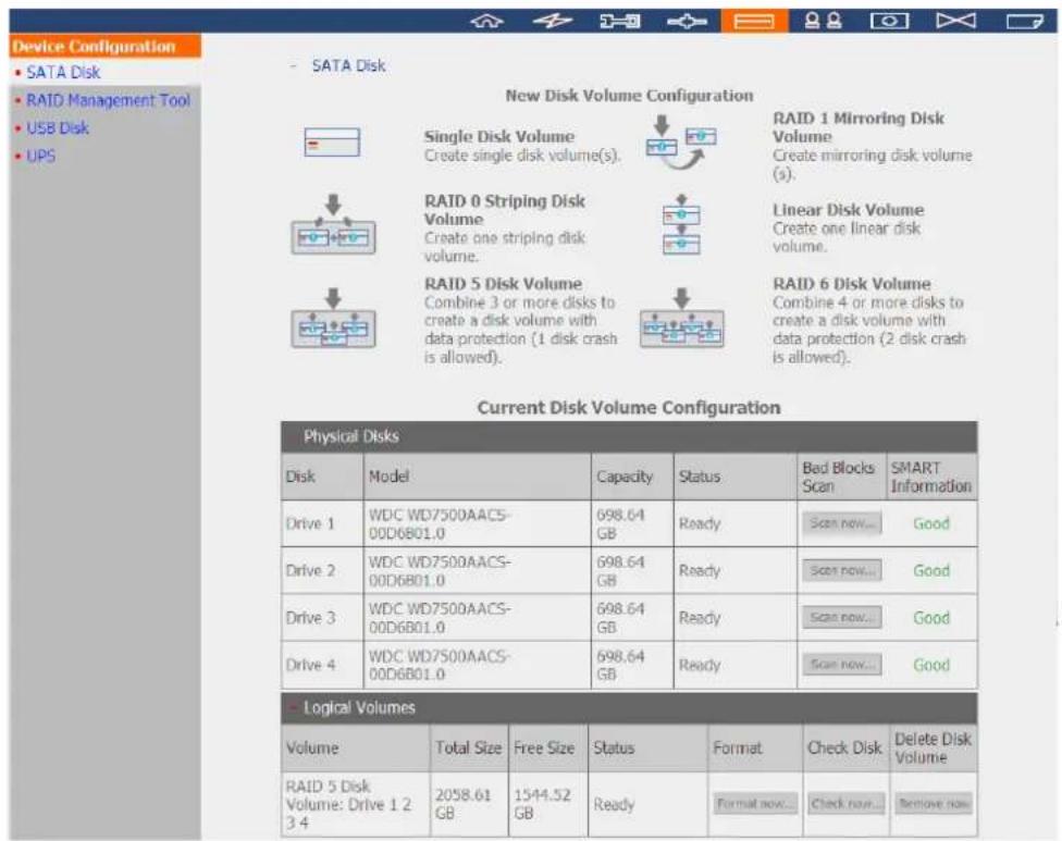
Click the icons on the "SATA Disk" page to format the hard disk drive(s).
| Disk Configuration Applied NVR Models | |
| Single disk volume All models | |
| RAID 1, JBOD (just a bunch of disks) 2-bay models or above | |
| RAID 5, RAID 6, RAID 5+hot spare 4-bay models or above | |
| RAID 6+hot spare 5-bay models or above | |
| Single Disk VolumeEach hard disk drive is used as a standalone disk. If a disk is damaged, all the data will be lost. | |
| JBOD (Just a bunch of disks)JBOD is a collection of hard disk drives that does not offer any RAID protection. The data are written to the physical disks sequentially. The total storage capacity equals to the sum of the capacity of all the member drives. | 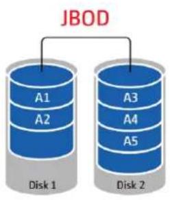 |
| RAID 0 Striping Disk VolumeRAID 0 (striping disk) combines 2 or more hard disk drives into one larger volume. The data is written to the hard disk drives without any parity information and no redundancy is offered. The disk capacity equals the number of hard disk drives in the array times the size of the smallest hard drive. | 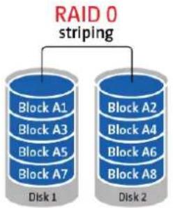 |
| RAID 1 Mirroring Disk VolumeRAID 1 duplicates the data between two hard disk drives to provide disk mirroring. To create a RAID 1 array, a minimum of 2 hard drives are required. |  |
| RAID 5 Disk VolumeThe data are striped across all the drives in a RAID 5 array. The parity information is distributed and stored across each drive. If a member drive fails, the array enters degraded mode. After installing a new drive to replace the failed one, the data can be rebuilt from other member drives that contain the parity information. | 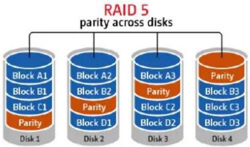 |
| To create a RAID 5 disk volume, a minimum of 3 hard disks are required.The storage capacity of a RAID 5 array equals (N-1). N is the total number of drive members in the array. | |
| RAID 6 Disk VolumeThe data are striped across all the drives in a RAID 6 array. RAID 6 differs from RAID 5 that a second set of parity information is stored across the member drives in the array. It tolerates failure of two member drives. To create a RAID 6 disk volume, a minimum of 4 hard disks are required. The storage capacity of a RAID 6 array equals (N-2). N is the total number of drive members in the array. |  |
6.4.2 RAID Management Tool
*This function is not supported by the VS-101, VS-201, NVR-104.
The RAID management tool allows you to carry out capacity expansion, RAID migration, or spare drive configuration with the original drive data reserved.
- RAID Management Tool
This function enables capacity expansion, RAID configuration migration or spare drive configuration with the original drive data reserved.
Note: Make sure you have read the instructions carefully and you fully understand the correct operation procedure before using this function.
Current Disk Volume Configuration
| Volume | Total Size | Status | Comment |
| ○ Mirroring Disk Volume: Drive 12 | 456.98 GB | Ready | The operation(s) you can execute:- Expand capacity |
The operation(s) you can execute:
Energe capacity
and therefore
Figure
Configure spare drive
Comment
- Expand capacity
This function enables capacity expansion of a RAID configuration by replacing the member drives one by one. This option is supported by RAID 1, RAID 5, or RAID 6 configurations.
- Add hard drive
This function enables adding new drive member to a RAID configuration. It is supported by RAID 5 configuration.
- Migrate
This function enables a drive configuration to be migrated to a different RAID configuration. You can use this feature to:
- Migrate a single drive to RAID 1, 5, or 6
- Migrate a RAID 1 configuration to RAID 5 or 6
- Migrate a RAID 5 configuration to RAID 6
- Configure spare drive
This function enables adding or removing a spare drive from a RAID 5 configuration. The options available are:
- Add a spare drive to a RAID 5 configuration
- Remove a spare drive from a RAID 5 configuration
For detailed operation instructions, click "Comment" on the management interface.
6.4.3 USB Disk
The NVR supports data backup to the external USB storage devices. Connect the USB storage device to the USB port of the NVR, when the device is successfully detected, the details will be shown.
* The VS-101/VS-201/NVR-104 do not support FAT32 and NTFS.
- USB Disk
Manufacturer: IC25N040
Model: ATCS04-0
Device Type: USB 2.0
Total / Free size: 38154 MB / 38087 MB
File System: NTFS
Status: Ready
Format As: NTFS Format now...
Unplug: Unplug now...
To remove the hardware device, please click [Unplug now...]. When the system does not show the device anymore, you can remove it safely.
Note: Do NOT unplug the device when it is in use to protect the device.
6.4.4 UPS
You can connect a UPS (uninterruptible power supply) to the NVR and enable the UPS support. When an expected power outage occurs, the UPS is able to supply the power to the NVR continuously. You can also configure the settings to turn off the NVR after the AC power fails. If the power of the UPS is insufficient to last for the time specified, the NVR will shut down immediately for optimized server protection.
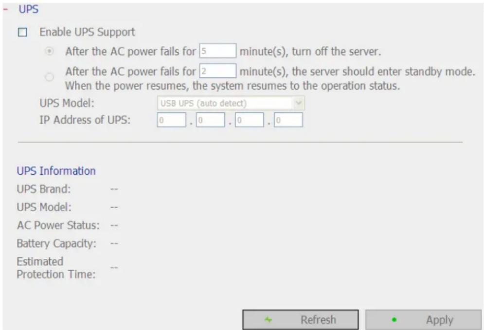
* It is recommended to connect the UPS to one of the USB ports on the rear side of the NVR.
- Enable UPS Support
Check this option to enable the UPS support. Enter the time the NVR should wait before shutting down after the AC power fails. In general, the UPS can supply the power for 5-10 minutes when AC power fails depending on the maximum load and the number of connected devices.
- UPS Model
Select the UPS model on the list. If your UPS is not available on the list, please contact the distributor or QNAP technical support.
- IP Address of UPS
If you select to use "APC UPS with SNMP Management", enter the IP address of the UPS.
Note: It is recommended to use APC Smart-UPS 700+ APC Network Management Card.
6.5 User Management
The NVR supports secure user access right management. A user can be defined as an administrator, a system manager, or a general user and given different rights of monitoring, playback, and system administration.
Note: The NVR supports up to 32 users (including the system default users).
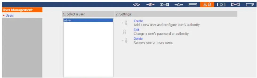
The NVR supports 3 types of users:
1. administrator
The system default administrator accounts are "admin" and "supervisor" (default password: admin). Both of them have the rights of system administration, monitoring, and playback. The administrators cannot be deleted. They have the rights to create and delete new administrators, system managers, and general users, and change their passwords. Other newly created "administrators" have the rights of system administration, monitoring, and playback but some rights are different from "admin" and "supervisor". Please refer to Chapter 6.5.4 for more details.
2. system manager
The default system manager account is "sysmgr" (default password: admin). This account has the right of system administration and cannot be deleted. "sysmgr" can create and delete other system manager and general user accounts, and assign monitoring, playback, and administration rights to them. Other newly created system managers will also have the administration right but some rights are different from "sysmgr". Please refer to Chapter 6.5.4 for more details.
3. user
The general users have only the rights of monitoring and video playback. They have no administration authority. Please refer to Chapter 6.5.4 for more details.
6.5.1 Create user
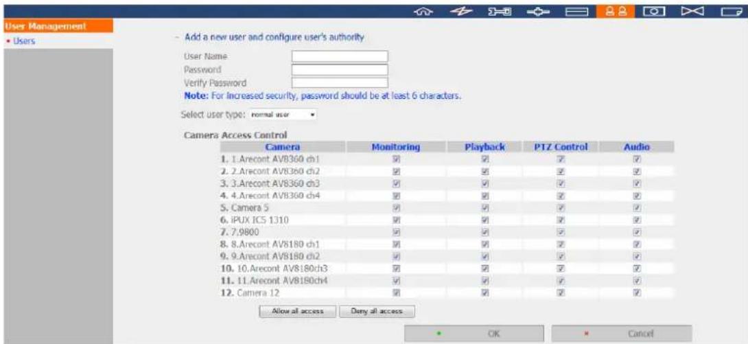
- User Name
The user name must be 1 to 32 characters in length. It supports alphabets (A-Z), numbers (0-9), and underscore (_). It is case-insensitive and supports double-byte characters, such as Chinese, Japanese, and Korean but cannot be a pure number or contain the following characters:
" / []:; | = , + *? lt; gt; ^
- Password
The password is case-sensitive and supports maximum 16 characters. It is recommended to use a password of at least 6 characters.
- Select user type
Define the user as an administrator, system manager, or general user.
- Camera Access Control
Assign the rights of monitoring (video/audio), playback, and PTZ control to the user.
Note: Please refer to Chapter 6.5.4 for further information of the user access rights.
6.5.2 Edit User
Select a user on the list and click "Edit". You can change the password; assign the rights of system administration and camera access to the user. However, the user name cannot be changed.
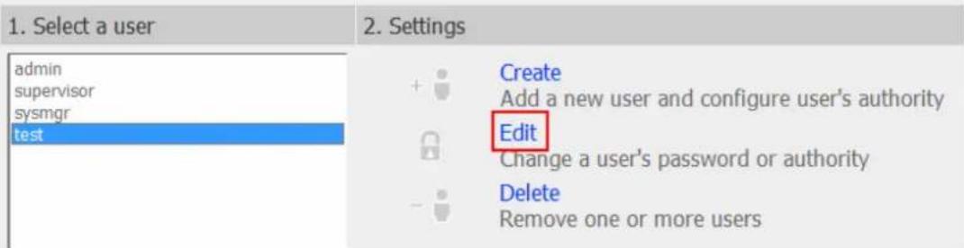
6.5.3 Delete User
To delete a user, select the user on the list and click "Delete". Click "OK" to confirm.

Note: The system administrator (admin, supervisor, sysmgr) cannot be deleted.
6.5.4 User Access Rights Comparison
VioStor NVR supports three types of users including system administrator, system manager, and general user. The default system administrators are "admin" and "supervisor" who cannot change one another's password, user type, and access rights to the IP cameras.
Note 1: The user can delete his/her account
Note 2: The user can change his/her password
| administrator | system manager | user | |||||
| Rights | admin | Other supervisor administrators | sysmgr | Other system managers | User | ||
| 1. Create new "admin" account | Default | Default | No No | No | No | ||
| 2. Create new "supervisor" account | Default | Default | No No | No | No | ||
| 3. Create new administrator accounts | Yes | Yes | Yes | No | No | No | |
| 4. Delete other administrator accounts | Yes | Yes | No (Note 1) No | No | No | ||
| 5. Change the password of "admin" | Yes | No | No | No | No | No | |
| 6. Change the password of "supervisor" | No | Yes | No | No | No | No | |
| 7. Change the password of other administrators | Yes | Yes | No (Note 2) | No | No | No | |
| 8. Change the user type of admin | Default | No | No No | No | No | ||
| 9. Change the user type of supervisor | No | Default | No | No | No | No | |
| 10. Change the user type of other administrators | Yes | Yes | Default | No | No | No | |
| 11. Change the camera access control of admin | Yes | No | No | No | No | No | |
| 12. Change the camera access control of supervisor | No | Yes | No | No | No | No | |
| 13. | Change the camera access control of other administrators | No | No | Yes | No | No | No | |
| 14. | Create sysmgr No No | No Default | No No | No | ||||
| 15. | Create other system manager accounts | Yes | Yes | Yes | Yes | Yes | ||
| 16. | Delete sysmgr No No | No No No | No | |||||
| 17. | Delete other system manager accounts | Yes | Yes | Yes | Yes | No (Note 1) | No | |
| 18. | Change the password of sysmgr | Yes | Yes | Yes | No (Note 2) | No | No | |
| 19. | Change the password of other system managers | Yes | Yes | Yes | Yes | No (Note 2) | No | |
| 20. | Change the user type of sysmgr | No | No | No | Default | No | No | |
| 21. | Change the user type of other system managers | Yes | Yes | Yes | Yes | No | No | |
| 22. | Change the camera access control of sysmgr | No | No | No | No | No | No | |
| 23. | Change the camera access control of other system managers | No | No | No | No | No | No | |
| 24. | Create new users | Yes | Yes | Yes | Yes | Yes | No | |
| 25. | Delete users | Yes | Yes | Yes | Yes | Yes | No | |
| 26. | Change the user password | Yes | Yes | Yes | Yes | No | No | |
| 27. | Change the user type of normal users | Yes | Yes | Yes | Yes | No | No | |
| 28. | Change the camera access control of normal users | Yes | Yes | Yes | Yes | Yes | No | |
| 29. | System administration | Yes | Yes | Yes | Yes | Yes | No | |
| 30. | Monitoring | Yes | Yes | Yes | No | No | Default | |
| 31. | Playback | Yes | Yes | Yes | No | No | Default | |
| 32. | Open data encryption password | Yes | Yes | No | No | No | No |
6.6 Camera Settings
You can configure the IP camera, recording, schedule, alarm, and advanced settings.
6.6.1 Camera Configuration
Please follow the steps below to configure the IP cameras.
- Select a camera number.
- Select the camera brand.
- Select the camera model.
- Enter the camera name.
- Enter the IP address or domain name of the camera.
- Enter the user name and the password to login the camera.
- Select to enable the recording or not.
- Click "Apply" to save the settings.

Note:
- All the settings will not take effect until you click "Apply". When applying the changes, the recording operation will stop for a while (maximum 1 minute) and then restart.
- Click "Search" to search for the IP cameras on the local network. Select a channel for the IP camera and click "Add" to add the camera. By using the search function, the camera model and the IP address are filled in automatically. Click "Close" to close the search results.
Add generic IP camera support by the CGI command
The NVR provides an interface for the users to enter the JPEG CGI command of the IP cameras in order to receive the video and audio streaming data from the IP cameras and monitor, record, and playback the video of the IP cameras on the NVR.
Follow the steps below to configure your IP camera.
- Select the IP camera number.
- Select "Generic Model" for the camera brand.
- Select "Generic JPEG" for the camera model.
- Enter the cgi path of the IP camera in the "HTTP URL" field.
- Enter the camera name or the IP address of the camera.
- Enter the user name and the password of the IP camera.
- Select to enable the recording or not.
- Click "Apply" to save the settings.
Camera Configuration
| Camera Name | Brand | IP Address | WAN IP Address | |
| 1 | 1. ACTi ACD-2000Q | ACTi | 172.17.26.85 | |
| 2 | Camera 2 | |||
| 3 | 3. Sanyo HD4000 | Sanyo | 172.17.26.230 | |
| 4 | 4. ACTi ACM-4200 | ACTi | 172.17.26.201 | |
| 5 | Camera 5 | |||
| 6 | Camera 6 | |||
| 7 | 7. Uivotek P27151 | Uivotek | 172.17.27.90 | |
| 8 | 8. QNAP VC300 ch1 | QNAP | 172.17.26.174 |

(for monitoring from public network *)

√ Enable recording on this camera

Note: All the camera configuration will not take effect until you click the "Apply" button. * If your IP camera is installed behind NAT router, you may input the public IP address (or URL) and the corresponding forwarded port of the router.
Note: The QNAP NVR only supports JPEG CGI command interface, but does not guarantee the compatibility with all the IP camera brands.
6.6.2 Recording Settings
Select a camera on the list and configure the recording resolution, frame rate, and quality. You can also enable the manual recording. Click "Apply" to save the settings.
Recording Settings
| Camera Name | Resolution | Frame Rate | Quality | |
| 1 | Eastman Quad | 320x240 | 3 | Standard |
| 2 | Denmark | 320x240 | 3 | Compression 50 |
| 3 | Shishmaref | Medium | 3 | Q=50 |
| 4 | Shinagawa | Medium | 3 | Q=50 |
| 5 | Airport | 4CIF | Full | Compression 50 |
| 6 | Puako Hawaii US | CIF | Full | Compression 50 |
| 7 | Hotel Forum Rome | CIF | Full | Compression 50 |
| 8 | Australia | CIF | 3 | Compression 50 |
| 9 | Webcamera | 320x240 | Full | Compression 50 |
| Camera Number: | 1: Eastman Quad |
| Video Compression: | Motion JPEG |
| Resolution: | 320x240 |
| Frame Rate: | 3 |
| Quality: | Standard |
□ Enable audio recording on this camera
Estimated Storage Space for Recording: 140 MB / Hour
Enable manual recording
Apply
Note: All the settings will not take effect until you click the Apply button. When applying the changes, recording will stop for a while (maximum 1 minute) and then restart.
- Video compression: Choose a video compression format for the recording.
- Resolution: Select the recording resolution.
- Frame rate: Adjust the frame rate for the recording. Note that the frame rate of the IP camera may be affected by the network traffic.
- Quality: Select the image quality for the recording. More disk space is required to save higher quality recording.
- Audio recording (optional): To enable the audio recording, click "Enable audio recording on this camera".
- Estimated storage space for recording: The number of the estimated storage space for recording is only for reference. The actual space required depends on the network environment and the camera performance.
- Manual recording: To allow manual activation and deactivation of manual recording function on the monitoring page, enable this option.
Note:
- Starting and stopping the manual recording will not affect the scheduled or alarm recording tasks. They are independent processes.
- All the settings will not take effect until you click "Apply". When applying the changes, the recording will stop for a while (maximum 1 minute) and then restart.
6.6.3 Schedule Settings
You can select continuous recording or scheduled recording. The default setting is continuous recording. To set up a recording schedule, select a camera number on the list. Then select the date and time and click "Add". Click "Apply" to save the settings for the particular IP camera or click "Apply to all cameras" to apply the settings to all the IP cameras. To delete a schedule, click "Remove" on the schedule list.
Schedule Settings
| Camera Name | IP Address | Scheduled Recording | |
| 1 | 1.Panasonic HCN-481 | 172.17.26.170 | ON |
| 2 | 2.HCM-311-A | 172.17.26.117 | ON |
| 3 | 3.HCM-403/LAB-A | 172.17.27.220 | ON |
| 4 | 4.HCM-311/RD-A | 172.17.24.31 | ON |
| 5 | 5.HCM 381 /R/ | 172.17.27.62 | ON |
| 6 | 6.HCM-371 /RD-A | 172.17.25.253 | ON |
| 7 | 7.Panasonic HCE-481 | 172.17.27.134 | ON |
| 8 | 8. Sony CS-10 | 172.17.26.61 | ON |
Camera Number: 1:1.Panasonic HCM-481
Enable schedule recording
Recording Schedule
Days:
Sun
Mon
Tue
Wed
Thu
Fri
Sat
Select all
Duration:
All day
○ Start time:
End time:

Add
Clear Schedule List
Schedule List: (15 Max)
Sun, Mon, Tue, Wed, Thu, Fri, Sat: 00:00 \~ NextDay 00:00
Remove
Apply
Apply to all cameras
Note: All the settings will not take effect until you click the Apply button. When applying the changes, recording will stop for a while (maximum 1 minute) and then restart.
Note:
- You can add up to 15 schedules.
- All the settings will not take effect until you click "Apply". When applying the changes, the recording will stop for a while (maximum 1 minute) and then restart.
6.6.4 Alarm Settings
The NVR provides the "Traditional Mode" and the "Advanced Mode" for the alarm settings. Select the "Traditional Mode" to use the standard alarm settings in response to the alarm events. To use the advanced event management, select the "Advanced Mode".
Note: The VS-201/VS-101/NVR-104 does not support the Advanced Mode in the "Alarm Settings".
Traditional Mode
Select a channel (IP camera/video server) on the list and configure the alarm settings. The video recording will be activated when the alarm input of the selected channel is triggered or a moving object is detected.
When you enable the option "Activate alarm recording only on selected schedule", the alarm recording will be activated only when the alarm input is triggered or a moving object is detected within the schedule. You can test the settings by clicking "Test". Click "Apply" to apply the settings to the selected channel. To apply the same settings to all the channels on the list, click "Apply to all cameras".
- Alarm Settings
Traditional Mode Advanced Mode
| Camera Name | IP Address | Alarm Recording | |
| 4 | 4.Arecont AV8360 ch4 | 172.17.26.85 | ON |
| 5 | Camera 5 | ||
| 6 | iPUX ICS 1310 | 172.17.27.170 | ON |
| 7 | 7.9800 | 172.17.27.53 | ON |
| 8 | 8.Arecont AV8180 ch1 | 172.17.26.56 | ON |
| 9 | 9.Arecont AV8180 ch2 | 172.17.26.56 | ON |
| 10 | 10.Arecont AV8180ch3 | 172.17.26.56 | ON |
| 11 | 11.Arecont AV8180ch4 | 172.17.26.56 | ON |
Camera Number: 6:iPUXICS 1310
√ Enable alarm recording
√ Start recording when motion is detected by the camera
√ Activate alarm recording only on selected schedule
Basic Mode Advanced Mode
Days: All Days
Duration:
All day Start time: 00 : 00 End time: 10 : 00
☐ Manually specify the alarm FTP server address of the camera
Test
Apply
Apply to all cameras
Note: All the settings will not take effect until you click the Apply button. When applying the changes, recording will stop for a while (maximum 1 minute) and then restart.
Note:
- All the settings will be effective after you click "Apply". When applying the changes, the current recording process will stop for a while (maximum 1 minute) and then restart.
- To avoid blocking by the firewall, the IP cameras or the video servers configured for the alarm recording must be located on the same subnet as the NVR.
- To switch from the traditional mode to the advanced mode, select "Advanced Mode" and click "Go to the settings page".
Advanced Mode:
The advanced mode consists of the event and action sections. You can define the action to take for each event triggered on the IP cameras or the video servers connected to the NVR.
To configure the advanced event management by the "Advanced Mode", select an event type on the left channel list and configure the actions to take on the right.
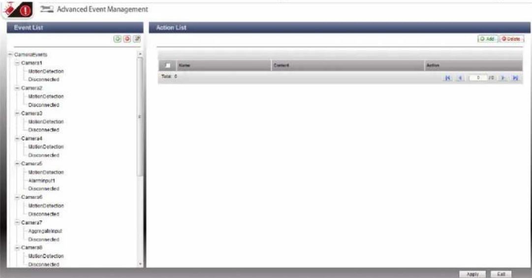
Note:
- Click "Apply" to apply the settings or "Exit" to exit the settings page. If the "Advanced Mode" is selected on the "Alarm Settings" page, the advanced settings will be applied after the NVR restarts even if you have selected to exit the settings page. The settings will be cancelled if you select to use "Traditional Mode" after exiting the "Advanced Mode".
- To avoid blocking by the firewall, the IP cameras or the video servers configured for the alarm recording must be located on the same subnet as the NVR.
- To switch from the advanced mode to the traditional mode, select "Traditional Mode" and click "Apply".
- Events:
The events supported by the NVR are classified as camera events (motion detection, alarm input, camera disconnection), NVR events (recording failure), and external events (user-defined events).
Note: The camera events available vary according to the features supported by the IP cameras or video servers.
Buttons on the event list
| Add an external event. This button is not applicable to the camera events and the NVR events. | |
| Edit an event. This button cannot be used to edit camera disconnection. | |
| Delete an external event. This button is not applicable to the camera events and the NVR events. |

The NVR supports the following event types. Before you define the action settings, select the events to manage and configure the settings.
(1) Alarm input
This option allows the NVR to trigger an action when the alarm input of the IP camera or the video server is triggered. Select "Camera event" from the "Event List". Locate the channel which supports alarm input and click "Alarm Input". Next, click the edit button (☐), enable this option, configure the settings, and click "Apply". You may also set the schedule to define the active period of the alarm settings. After that, define the action on the right (discussed in the later sections).
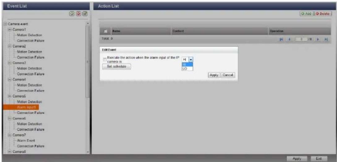
(2) Motion detection
This option allows the NVR to trigger an action when a moving object is detected by the IP camera or the video server. Select "Camera event" from the "Event List". Locate the channel and click "Motion Detection". Next, click the edit button (☐), enable this option, configure the settings, and click "Apply". You may also set the schedule to define the active period of the alarm settings. After that, define the action on the right (discussed in the later sections).

(3) Alarm event
The alarm input and the motion detection settings of some IP cameras or video servers may be combined together and called "Alarm Event" on the Event List. You can edit the event settings and define the action on the right (discussed in the later sections).

(4) Connection failure
This option allows the NVR to trigger an action when the IP camera or the video server is disconnected. Select "Camera Event" from the "Event List". Locate the channel and click "Connection Failure". After that, define the action on the right (discussed in the later sections).

(5) Recording failure (NVR event)
This option allows the NVR to trigger an action when the video recording of the IP camera or the video server fails due to the hard disk bad blocks, file system crash, or other reasons. Select "NVR event" from the "Event List". Click "Recording failure". Then define the action settings on the right (discussed in the later sections).
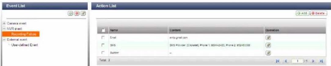
(6) External event (user-defined events)
To create a self-defined event on the NVR, select "User-defined Event" under "External event" on the "Event List". Then click the + button. Enter the event name, for example, "door".
After creating an event, click the event name and define the action on the right (discussed in the later sections). After configuring the action settings, you can enter the CGI command (including the self-defined event name) in the web browser (Internet Explorer) to trigger the action anytime. The format of the CGI command is:
http://NVRIP/cgi-bin/logical_input.cgi?name=event-name. For example, http://10.8.12.12:80/cgi-bin/logical_input.cgi?name=door

Event schedule settings:
When you edit an event (not including camera disconnection, NVR events, and external events), you can click "Set Schedule" to define when the alarm settings will be active.
To create a new schedule, select "New" and enter the schedule name. The schedule supports maximum 25 characters (double-byte characters, spaces, and symbols are allowed). Select the day and time when the alarm settings should be active. Click + to add a schedule; or – to delete a schedule. Up to 6 settings can be defined for each schedule.
The settings will be shown on the graphical table. Click "Apply" to save the settings. To use the same schedule for all the events, click "Apply to All Events". You can also select to use the default schedule or a formerly created schedule from the list. The default alarm settings are active all day, every day.
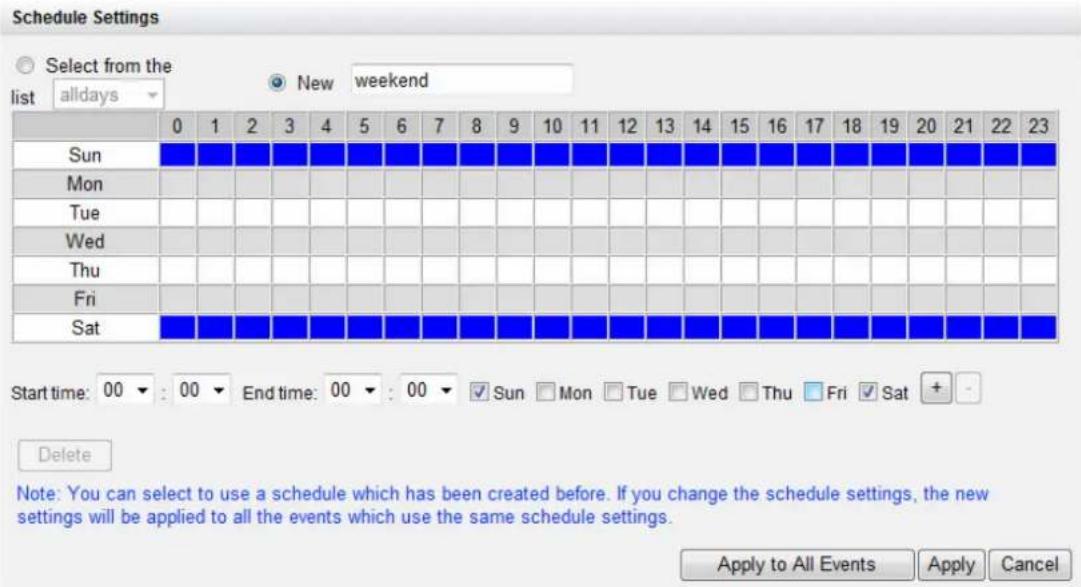
- Actions:
The NVR supports different actions which can be activated when the selected events are triggered on the IP cameras or the video servers. The actions include video recording, email alert, SMS alert, buzzer, PTZ camera control, alarm output, and logic output.
Buttons on the action list
| Add an action:After configuring an event on the left, click "Add" to create an action in response to the event. Click "Apply" to save the settings. | |
| Edit an action:Select an event on the left. All the actions defined for this event will be shown. Check the box in front of the action name you want to edit. Then click this button on the "Action" column to edit the action settings. | |
| Delete an action:Select an event on the left. All the actions defined for this event will be shown. Check the box in front of the action name you want to delete and click "Delete". You can select to delete multiple actions. |
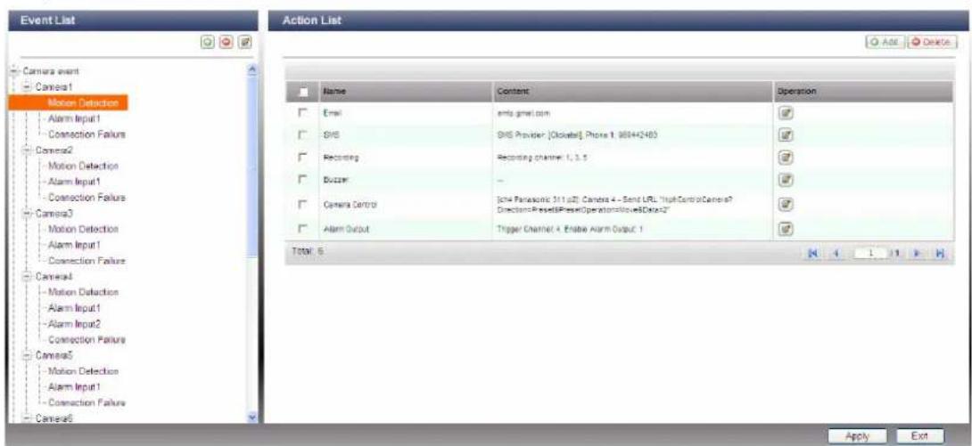
Note: Make sure you have enabled the action in the event settings; otherwise the action will not be executed. For example:
Edit Event
√ Execute the action when a moving object is detected by the IP camera
☐ Specify the FTP address for the NVR to receive the alarm messages from the IP camera (optional)
IP Address 0
Port: 0
Set schedule
Apply
Cancel
(1) Recording
Select the channels (IP cameras or video servers) which will start recording when an event occurs. You may also select the following options:
(i) Enter the time (in seconds) the recording should be executed after the event is triggered.
(ii) Start recording when the event starts and stop recording when the event ends.
The option (ii) is applicable to the duration events only. A duration event is an event with the start and end time and lasts for a period of time. It does not include the events related to status change, such as camera disconnection or NVR recording failure.
If the action is triggered by a duration event and both settings (i, ii) are enabled, the NVR will execute the second setting (ii) only.
Click "Select from the list" to select an action setting which has been configured before.
Add Action
Action Type:
Recording


New

Select from the list
Select one or more channels to start recording when an event is triggered.
Ch-01
□ Ch-02
□ Ch-03
□ Ch-04
□ Ch-05
□ Ch-06
□ Ch-07
□ Ch-08
□ Ch-09
□ Ch-10
□ Ch-11
□ Ch-12
Execute the action for: 30 second (s) when the event is triggered □ Execute the action when the event starts and stop the action when the event ends*.
* This option is applicable to duration events only. If the action is activated by duration event and both settings above are enabled, the NVR will execute this setting only. Note: A duration event is an event with start and end time and lasts for a period of time. It does not include the events related to status change, such as camera's connection failure or NVR recording failure.
Apply to All Events Apply Cancel
(2) Camera control
This option allows you to configure the PTZ camera to adjust to the preset position for monitoring or act according to the HTTP URL entered when an event is triggered. You can select a preset position from the drop-down menu or enter the HTTP URL.
Click "Select from the list" to select an action setting which has been configured before.
Note: The preset names will appear only after you have configured the preset position settings of the PTZ cameras.

(3) Alarm output
Select to activate the alarm device connected to the IP camera when an event is triggered. You may also select the following options:
(i) Enter the number of second(s) the alarm device will be active when the event is triggered.
(ii) Activate the alarm device when the event starts and stop the alarm device when the event ends.
The option (ii) is applicable to the duration events only. A duration event is an event with the start and end time and lasts for a period of time. It does not include the events related to status change, such as camera disconnection or NVR recording failure.
Click "Select from the list" to select an action setting which has been configured before.
Add Action
Action Type:
Alarm Output


New

Select from the list
Select an alarm output of the IP camera. The alarm will be activated when an event is triggered.
Camera Number:

Note: Only the IP camera models of which the alarm output is supported by the NVR will be listed.
Execute the action for: 30 second (s) when the event is triggered
☐ Execute the action when the event starts and stop the action when the event ends*.
* This option is applicable to duration events only. If the action is activated by duration event and both settings above are enabled, the NVR will execute this setting only. Note: A duration event is an event with start and end time and lasts for a period of time. It does not include the events related to status change, such as camera's connection failure or NVR recording failure.
Apply to All Events
Apply
Cancel
(4) Email
To allow the system administrator to receive an instant email alert when an event is triggered, enter the SMTP settings. Multiple email addresses can be entered as the recipients. You may also select to attach the snapshots of the multiple channels (IP cameras/video servers) available on the NVR.
Click "Select from the list" to select an action setting which has been configured before.

(5) SMS
To allow the system administrator to receive an instant SMS alert when an event is triggered, enter the SMS server settings. The default SMS service provider is Clickatell. To add other SMS service providers, click "Add" and enter the provider's name and the URL template text.
Click "Select from the list" to select an action setting which has been configured before.
Note: You will not be able to receive the SMS properly if the URL template text entered does not follow your SMS service provider's standard.
![[SMS Server Settings] SMS Service Provider Clickatell Create Edit Delete Enable SSL Connection SMS Server Login Name qnap01 SMS Server Login Password ••••••• SMS Server API_ID 3116393 [SMS Notification Settings] Country Code: Afghanistan (+93) Cell Phone No. 1: +93 Cell Phone No. 2: +93 Message: Tes…](/content/2026/06/1279227/images/341d10b85e2c91fd73a803ee16738e066a8baa99f5c9277c6063deebca4cd686.jpg)
(6) Buzzer
Enable the buzzer when an event is triggered. You may also select the following options:
(i) Enter the time (in seconds) the buzzer will sound when the event is triggered.
(ii) Execute the buzzer when the event starts and stop the buzzer when the event ends.
The option (ii) is applicable to the duration events only. A duration event is an event with the start and end time and lasts for a period of time. It does not include the events related to status change, such as camera disconnection or NVR recording failure.
If the action is triggered by a duration event and both settings (i, ii) are enabled, the NVR will execute the second setting (ii) only.
Click "Select from the list" to select an action setting which has been configured before.
Add Action
Action Type:
Buzzer


New

Select from the list
Enable the buzzer on the NVR. The buzzer will sound when an event is triggered.
Test
Execute the action for: 30 second (s) when the event is triggered
☐ Execute the action when the event starts and stop the action when the event ends*.
* This option is applicable to duration events only. If the action is activated by duration event and both settings above are enabled, the NVR will execute this setting only.
Note: A duration event is an event with start and end time and lasts for a period of time. It does not include the events related to status change, such as camera's connection failure or NVR recording failure.
Apply to All Events
Apply
Cancel
(7) User-defined Action
You can enter a self-defined action when an event is triggered. Enter the login account and password, IP address, port, and the HTTP URL of other surveillance devices. You can manage the devices such as fire protection devices, power controller, and air conditioning control.
Click "Select from the list" to select an action setting which has been configured before.

6.6.5 Advanced Settings
You can configure the advanced recording settings in this section.
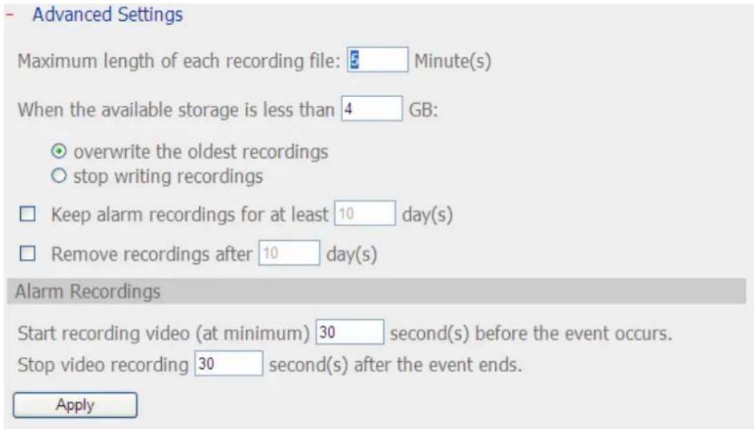
Note: All the settings will not take effect until you click the Apply button. When applying the changes, recording will stop for a while (maximum 1 minute) and then restart.
● Maximum period for each recording file: Configure the maximum length of each recording file (maximum 15 min).
- When the available storage is less than...GB: Select the action to take when the available storage is less than the preset level. You can select to overwrite the oldest recordings or stop recording the new videos.
- Keep alarm recordings for at least...day(s): Specify the number of days that alarm recordings will be retained. This will prevent the recording files from being overwritten when the free storage space is insufficient.
- Remove recordings after...day(s): Enter the number of calendar days for VioStor to keep the recording files.
Please make sure your storage capacity is enough to save the data for the number of calendar days you set. When the recording data has reached the expiry date, all the expired video files will be deleted. For example, if you set to delete the recording data after 7 calendar days, on the 8th day, the files recorded on the first day of each camera will be deleted so that VioStor can start to save the data on the 8th day.
● Pre-/Post-alarm Recordings
■ Start recording video...second(s) before the event occurs: Enter the number of seconds to start the recording before an event occurs.
■ Stop video recording...second(s) after the event ends: Enter the number of seconds to stop the recording after an event ends.
The maximum number of seconds for the above settings is 300, i.e. 5 minutes.
Note: All the settings will not be effective until you click "Apply". When applying the changes, the recording will stop for a while (maximum 1 minute) and then restart.
6.7 System Tools
The System Tools enable you to optimize the system maintenance and management. You can set the alert notification, restart or shut down the server, configure the hardware settings, update the system firmware, back up/restore/reset the system settings, set the E-map, and run the ping test.
6.7.1 Alert Notification
Enter the email address of the administrator and the IP address of the SMTP server. When an error occurs, e.g. power outage or a hard disk drive is unplugged, an alert email will be sent to the specified recipients automatically. You can go to the "Event Logs" to check the details of all the errors and warnings.
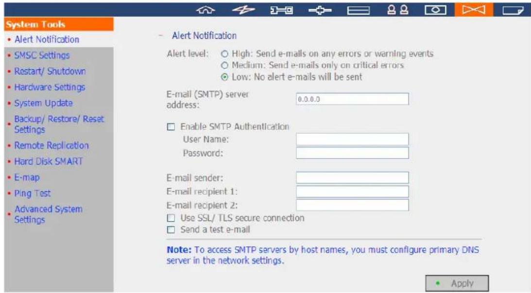
Note: It is recommended to send a test email to make sure the mail server settings are correct.
6.7.2 SMSC Settings
You can configure the SMSC (Short message service centre) settings to send the SMS text messages to the particular mobile phone numbers when an event takes place on the NVR. The default SMS service provider is Clickatell. You may also add your own SMS service provider by selecting "Add SMS Provider" from the drop-down menu.
When you select "Add SMS service provider", you need to enter the name of the SMS provider and the URL template text.
Note:
- You will not be able to receive the SMS properly if the URL template text entered does not follow the standard of your SMS service provider.
- Please send a test SMS to verify the settings are correct.
- When the "Advanced mode" is in use in the "Alarm Settings", this page will become inactive. You may go to "Camera Settings" > "Alarm Settings" > "Advanced Mode" to edit the SMS settings or select to use the "Traditional Mode" and configure the SMS settings on this page.
SMSC Settings
You can configure the SMSC settings to send instant system alerts via the SMS service provided by the SMS provider.
[SMS Server Settings]
SMS Service Provider
![QNAP VS-5012 - [SMS Server Settings] - 1](/content/2026/06/1279227/images/b60cde3eb98df2086f0c22eb20649df91c0f3a5cf64727f1aa0baddca60ba1fb.jpg)
http://www.clickatell.com
□ Enable SSL Connection
SSL Port:
![QNAP VS-5012 - [SMS Server Settings] - 2](/content/2026/06/1279227/images/a315dee466861fd5ed87d3d64172c00e179a26cd152779bcc966f63997a8b61e.jpg)
SMS Server Login Name
SMS Server Login Password
SMS Server API_ID
![QNAP VS-5012 - [SMS Server Settings] - 3](/content/2026/06/1279227/images/e8f4d4e46903ce22e58d52811f87b2df2b48f3227e767d8f24397312c93c0837.jpg)
[SMS Notification Settings]
Country Code: Afghanistan (+93)
Cell Phone No. 1: +93
Cell Phone No. 2: +93
![QNAP VS-5012 - [SMS Notification Settings] - 1](/content/2026/06/1279227/images/3f38a86c642be042917bdf8e08348a06d8f8644d6099a33906268a03362ff495.jpg)
(Do not enter the beginning "0".)
(Do not enter the beginning "0".)
☐ Send a test SMS message (If the SMSC settings are incorrect, you will not be able to receive the test message.)
Send SMS text messages when the following events take place:
□ Motion detection is detected on an IP camera
☐ Alarm input is triggered on an IP camera
□ An IP camera is disconnected
☐ The system fails to save recording files
Interval of sending SMS text messages of the same events: 60 Minute(s)
6.7.3 Restart/Shut Down
Follow the steps below to restart or shut down the server.
- Go to "System Tools" > "Restart/Shutdown".
- Click "Restart" to reboot the server or "Shut Down" to turn off the NVR.
- Restart/ Shutdown
To restart the server, click Restart.
To shut down the server, click Shut Down.
- Restart
- Shut Down
6.7.4 Hardware Settings
You can enable or disable the hardware functions of the NVR.

- Enable the configuration reset switch
By enabling this option, you can press the reset button for 5 seconds to reset the administrator password and system settings to default.
Note: The configuration reset switch is enabled by default. When this option is disabled, make sure you have kept your password safely. Otherwise, the NVR cannot be reset anymore if the password is lost.
● Auto power on when power resumes after power loss
When this function is enabled, the server will turn on automatically when the power resumes after a power loss.
- Enable front video backup button
VioStor supports direct copy of the recording data on the NVR to the connected USB device via the USB port. You can set the number of days that the videos are recorded to copy to the device. To use this function, please follow the steps below:
- Set the number of days that the latest recordings should be backed up. If 3 days are entered, the recordings of today, yesterday and the day before yesterday will be backed up.
- Connect a USB storage device, for example, USB disk drive to the front USB port of VioStor.
- Press and hold the video backup button for 3 seconds*. VioStor will start copying the recording data to the USB device instantly. If the USB device is recognized, the USB LED glows blue. The USB LED flashes blue when the data is being copied. The LED will become blue again when the data copy is finished. You can then safely remove the device.
Note: The video backup function supports only the USB devices of 10GB storage capacity or above.
This function is not supported by the VS-8040U-RP, VS-8032U-RP, VS-8024U-RP.
* If you are using the VS-101/VS-201/NVR-104, press the video backup button for 0.5 second to execute the data copy.
- Enable light signal alert when the free size of SATA disk is less than the value
The status LED flashes red and green when this function is enabled and the free space of the hard disk drive(s) on the NVR is less than the value. The range of the value is 1–51200 MB.
- Enable alarm buzzer
Enable this option to allow the NVR to sound when an error occurs.
● Enable redundant power supply mode
When the redundant power supply mode is enabled, the NVR beeps if any of the power supply units does not function properly.
*This function applies to the models with redundant power supply only.
After enabling the smart fan, the fan rotation speed is automatically adjusted according to the system temperature of the NVR. It is recommended to enable this option. By manually setting the fan rotation speed, the fan rotates at the defined speed continuously.
*This function is not supported by the VS-101, VS-201, NVR-104.
6.7.5 System Update
QNAP provides new firmware release for VioStor NVR from time to time to provide updated features and enhancements. You may update the system firmware in order to use these new features. Before updating the system firmware, make sure the product model and the firmware version are correct. Follow the steps below to update firmware:
- System Update
Note: If the system is running properly, you do not need to update the firmware.
Current firmware version: 3.1.0 Build 2012
Before updating system firmware, please make sure the product model and firmware version are correct. Follow the steps below to update firmware:
Step 1: Download the release notes of the same version as the firmware from QNAP website http://www.qnapsecurity.com/ Read the release notes carefully to make sure you need to update the firmware.
Step 2: Before updating system firmware, back up all disk data on the server to avoid any potential data loss during system update.
Step 3: Click the [Browse...] button to select the correct firmware image for system update. Click the [Update System] button to update the firmware.
Note: System update may take tens of seconds to several minutes to complete depending on the network connection status. Please wait patiently. The system will inform you when system update is completed.

Update System
Note: If the NVR is running properly, you may not need to update the firmware. QNAP is not responsible for any forms of data loss caused by improper or illegal system update.
- Download the release notes of the firmware from the QNAP website http://www.qnapsecurity.com/. Read the release notes carefully to make sure you need to update the firmware.
- Unzip the firmware file to your local computer.
- Before updating the system firmware, you are strongly suggested to back up all the disk data on the NVR to avoid any potential data loss during the system update.
- Click "Browse..." to select the correct firmware image. Click "Update System" to update the firmware.
The system update may take several minutes to complete depending on the network connection status. Please wait patiently. The NVR will inform you when
the system update is completed.
When updating the firmware, make sure the power supply is at a steady state.
Otherwise, the NVR may be unable to start up.
6.7.6 Backup/Restore/Reset Settings
- T o back up all the settings, including the user accounts, the server name and the network configuration, click "Backup" and select to open or save the setting file.
- To restore all the settings, click "Browse" to select a previously saved setting file and click "Restore".
- To reset all the settings to default, click "Reset". All the disk data will be deleted.
Caution: When you press "Reset" on this page, all the drive data, user accounts, network shares, and the system settings will be cleared and restored to default. Please make sure you have backed up all the important data and the system settings before resetting the NVR.
- Backup/ Restore/ Reset Settings
• To restore all settings, click Browse to select a previously saved setting file and click Restore to confirm.
- To backup all settings, including user accounts, server name and network configuration etc., click Backup and select to open or save the setting file.
• To reset all settings to default, click Reset.
Note: The web browser may ask you input the default password when resetting the system if it is not the same as the current password.
Browse...
6.7.7 Remote Replication
You can use the remote replication feature to copy the recording data of the local VioStor to a remote QNAP network attached storage (NAS). The remote QNAP NAS is hereafter referred to as "the remote storage device".
Note: Before using this function, make sure the Microsoft networking service of the remote storage device is enabled, and the corresponding path and user access right have been correctly configured.
- Login VioStor and go to "System Tools" > "Remote Replication".
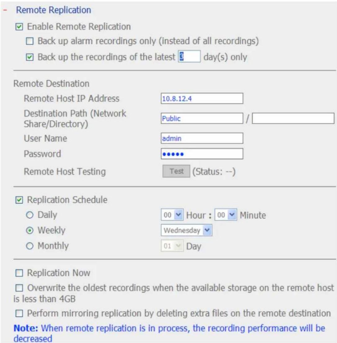
2. Enable remote replication (support multiple choices)

In the above example, the NVR only copies the alarm recording data of the latest 3 days to the remote storage device.
- Check the box "Enable remote replication" to activate this feature. The NVR executes automatic backup of the recording data to the remote storage device according to the settings.
- When you select "Back up alarm recordings only (instead of all recordings)", the NVR will only copy the alarm recording data to the remote storage device. If this option is unchecked, the NVR will back up all the recording data to the remote storage device.
- When you select "Back up the recordings of the latest...day(s) only" and enter the number of days, the NVR will back up the latest recording data to the remote storage device automatically according to your settings. If this option is unchecked, the NVR will copy all the recording data to the remote storage device.
3. Configure your remote storage server

Note: It is recommended to execute the "Remote host testing" function to verify the connection to the remote storage device is successful.
4. Configure the remote replication schedule
√ Replication Schedule
○ Daily
Weekly
○ Monthly

For example, to enable the NVR to copy the recording data automatically to the remote storage device at 01:15 every Monday, please do the following:
Check the box "Replication Schedule", select "Weekly", enter 01 Hour: 15 minute, and select "Monday".
5. Select the backup options
√ Replication Now
☑ Overwrite the oldest recordings when the available storage on the remote host is less than 4GB
Perform mirroring replication by deleting extra files on the remote destination
(a) Select "Replication Now", the NVR will back up the recording data to the remote storage device immediately.
(b) Select "Overwrite the oldest recordings when the available storage on the remote host is less than 4GB"; the NVR will overwrite the oldest recording data when the free space on the server is less than 4GB.
(c) Select "Perform mirroring replication by deleting extra files on the remote replication", the NVR will synchronize the recording data between itself and the remote storage device and delete any extra files on the remote storage device.
- When the above options are all checked and you execute the remote replication, the NVR will do the following:
i. The NVR checks if there are files on the remote storage device that are different from the local source. If yes, the differentiated files will be deleted.
ii. Next, the NVR checks the free space of remote storage device. If the free space is larger than 4GB, the remote replication will be executed immediately.
iii. If the free space of the remote storage device is less than 4GB, the NVR will overwrite the recording data of the oldest day and then executes the remote replication.
- The NVR displays the latest 10 remote replication records.
| Start Time | Finish Time | Replicated Data Size | Status |
| 2007-11-0818:00:07 | 2007-11-0906:29:39 | 54.36 GByte(s) | Succeeded |
| 2007-11-0718:00:06 | 2007-11-0810:18:26 | 74.17 GByte(s) | Succeeded |
| 2007-11-0618:00:02 | 2007-11-0619:56:31 | 12.24 GByte(s) | Succeeded |
| 2007-11-0518:00:06 | 2007-11-0520:05:06 | 12.53 GByte(s) | Succeeded |
| 2007-11-0418:00:03 | 2007-11-0419:59:28 | 11.33 GByte(s) | Succeeded |
| 2007-11-0318:00:08 | 2007-11-0320:01:54 | 11.75 GByte(s) | Succeeded |
| 2007-11-0218:14:09 | 2007-11-0219:11:16 | 4.98 GByte(s) | Failed (Remote access error) |
| 2007-11-0118:00:04 | 2007-11-0202:32:27 | 43.68 GByte(s) | Succeeded |
| 2007-10-3118:00:05 | 2007-11-0103:34:13 | 33.01 GByte(s) | Failed (An internal error occurred) |
In the above example:
- When the status is shown as "Failed (Remote access error)": You may check if the remote storage device is running or the network settings are correct.
- When the status is shown as "Failed (An internal error occurred)": You may check the hard drive status of VioStor or check the Event Logs.
Note: The time required by VioStor to replicate the data to the remote storage device varies depending on the network environment. If the remote replication takes too long, some recording files may be overwritten by the NVR. To avoid this, you are recommended to refer to the status messages to analyse the time required for the remote replication and adjust the replication schedule accordingly.
6.7.8 Hard Disk SMART
This function is not supported by the VS-101, VS-201, NVR-104.
This page enables you to monitor the health, temperature, and status of the hard disk drives by the S.M.A.R.T. (Self-Monitoring, Analysis, and Reporting Technology).
Select a hard disk drive to view the following information by clicking the corresponding buttons.
| Field Description | |
| Summary | Displays the summary and the latest test result of the hard disk drive. |
| Hard disk information | Displays the hard disk drive details such as the model, the serial number, and the drive capacity. |
| SMART information | Displays the hard disk drive S.M.A.R.T. The items of which the values are lower than the threshold are regarded as abnormal. |
| Test | To perform a quick or complete hard drive S.M.A.R.T. test and display the results. |
| Settings | To configure the temperature alarm. When the hard drive temperature is higher than the preset value, VioStor will record the error logs.You can also configure the quick and complete test schedule. The latest test result is shown on the Summary page. |
- Monitor hard disk health, temperature, and usage status by the hard disk S.M.A.R.T. mechanism.
Select hard disk:
Disk 1
Summary
Hard Disk Information
SMART Information
Test Settings
Good
No errors were detected on the hard disk. Your hard disk should be operating properly.
| Hard disk model | Seagate Barracuda 7200.10 family |
| Drive capacity | 298.09 GB |
| Hard drive health | Good |
| Hard drive temperature | 38 °C |
| Test time | Thu Oct 2 11:32:18 2008 |
| Test result | Test completed and no errors found(Rapid test) |
6.7.9 E-map
You can upload an E-map to VioStor to illustrate the location of the IP cameras.
- To upload an E-map, click "Browse" and select the file (JPEG only). Then click "Upload".
- You can change the caption of the E-map and click "Apply".
- After uploading the E-map, click "Test" to view the map.

Note: The uploaded E-map must be JPEG format.
6.7.10 Ping Test
To test the connection to an IP address, enter the IP address and click "Test".

6.7.11 Advanced System Settings
You can set the timeout period to log off the users from the configuration page of the NVR when the idling time has reached.
Note: The timeout logoff does not apply to the monitoring, playback, advanced mode, device configuration, system update, remote replication, and logs & statistics pages.
- Advanced System Settings
Logoff the user from the configuration page when the user is idle for more than 10 minutes.
Note: Timeout logoff does not apply to the monitoring, playback, advanced mode, device configuration, system update, remote replication, and Logs & Statistics pages.
Apply
6.8 Logs & Statistics
6.8.1 System Event Logs
The NVR can save maximum 10,000 recent event logs, including warning, error, and information messages. In case of system malfunction, the event logs (only in English) can be retrieved to analyse the system problems.
Click "Save" to save the logs as a csv file.

6.8.2 Surveillance Logs
This page shows the surveillance logs such as camera connection, motion detection, and camera authentication failure.
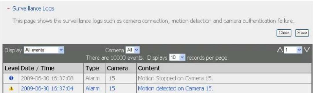
6.8.3 On-line Users List
This page shows the information of the currently active users, e.g. the user name, IP address, and login time.
- On-line Users
Display the information of the on-line users accessing the system via networking services
| Total 3 record(s). | ||||||
| Login date | Login time | Users | Source IP | Computer name | Connectio type | Accessed resources |
| 2009-06-30 | 16:13:29 | admin | 10.8.10.122 | --- | HTTP | Administration |
| 2009-06-29 | 16:55:00 | admin | 172.17.26.125 | --- | HTTP | Monitoring |
| 2009-06-29 | 16:54:22 | admin | 172.17.26.52 | --- | HTTP | Monitoring |
6.8.4 Historical Users List
This page shows the information of the users who have logged in the system including the user name, IP address, login time, and the services they have accessed etc.
- Historical Users List
Display the information of the users that have accessed the system via networking services
| Total 231 record(s). Displays 10 records per page. | ||||||
| Login date | Login time | Users | Source IP | Computer name | Connectio type | Accessed resources |
| 2009-06-30 | 15:14:33 | admin | 172.17.26.173 | --- | HTTP | Monitoring |
| 2009-06-30 | 15:34:38 | admin | 10.8.10.122 | --- | HTTP | Monitoring |
| 2009-06-30 | 15:34:38 | admin | 10.8.10.122 | --- | HTTP | Administration |
6.8.5 System Connection Logs
The connection logs to the NVR by samba, FTP, AFP, HTTP, HTTPS, Telnet, and SSH are recorded on this page.
You can select to start or stop the logging. The file transfer performance may be slightly affected by enabling the event logging.

6.8.6 System Information
This page shows the system information, such as the CPU usage, memory, and system temperature.

Chapter 7. System Maintenance
This section provides a general overview of the system maintenance.
7.1 Reset the Administrator Password and Network Settings
To reset the administrator password and the network settings, press the reset button of the server for five seconds. A beep sound will be heard.
After resetting the system, you can login the server with the default user name and password:
Default user name: admin* Password: admin
*If you are using the VS-201/VS-101/NVR-104, the default login name is "administrator" and the password is "admin".
Note: To reset the system by the reset button, the option "Enable configuration reset switch" in the "Hardware Settings" must be activated.

7.2 Power Outage or Abnormal Shutdown
In case of power outage or improper shutdown of the server, the server will resume to the state before it is shut down. If your server does not function properly after the restart, please do the following:
- If the system configuration were lost, configure the system again.
- If the problem persists, contact the technical support.
7.3 Hot Swapping Hard Disk Drives (RAID Configuration)
This function is not supported by the one-bay NVR models.
When a hard disk drive (HDD) of a RAID configuration fails, the failed HDD can be replaced by a new one immediately without shutting down the server, and the recording data can be reserved. However, if the HDD are working properly and the recording is in process, do not hot swap the HDD to avoid damage to the HDD or recording files.
Warning: You are strongly recommended to turn OFF the server before replacing the HDD to reduce the risk of electric shock.
Chapter 8. LCD Panel
* This section is applicable to the NVR models with an LCD panel only.
The NVR provides a handy LCD panel for you to perform the disk configuration and view the system information.
When the NVR has started up, you will be able to view the server name and the IP address:
| N | V | R | 5 | F | 4 | D | E | 3 | |||||||
| 1 | 6 | 9 | . | 2 | 5 | 4 | . | 1 | 0 | 0 | . | 1 | 0 | 0 |
For the first time installation, the LCD panel shows the number of the hard disk drives detected and the IP address. You may select to configure the hard drives.
| Number of hard drives detected | Default disk configuration | Available disk configuration options* |
| 1 Single | Single | |
| 2 | RAID 1 | Single -> JBOD ->RAID 0 -> RAID 1 |
| 3 | RAID 5 | Single -> JBOD -> RAID 0 -> RAID 5 |
| 4 or above RAID 5 | Single ->JBOD -> RAID 0 -> RAID 5-> RAID 6 | |
*Press the "Select" button to choose the option, and press the "Enter" button to confirm.
For example, when you turn on the NVR with 5 hard drives installed, the LCD panel shows:
| C o n f i g . D i s k s ? |
| → R A I D 5 |
You can press the "Select" button to browse more options, e.g. RAID 6.
Press the "Enter" button and the following message shows. Press the "Select" button to select "Yes" to confirm.
| C | h | o | o | s | e | R | A | I | D | 5 | ? | ||||
| → | Y | e | s | N | o |
When you execute RAID 1, RAID 5, or RAID 6 configuration, the system will initialize the hard drives, create the RAID configuration, format the RAID configuration, and mount it as a volume on the NVR. The progress will be shown on the LCD panel. When it reaches 100%, you can access the RAID volume, e.g. create share folders and upload files to the folders on the NVR. In the meantime, to make sure the stripes and blocks in the RAID configuration are ready, the NVR will execute RAID synchronization and the progress will be shown on the "Disk Management" > "Volume Management" page. The synchronization rate is around 30-60 MB/s (varied by hard disk drive models, system resource usage, etc.).
Note: If a member drive of the RAID configuration was lost during the synchronization, the RAID volume will enter degraded mode. The volume data is still accessible. If you add a new member drive to the volume, the volume will start to rebuild. You can check the status on the "Volume Management" page.
When the configuration has finished, the server name and the IP address will be shown. If the NVR fails to create the disk volume, the following message will be shown.
| C | r | e | a | t | i | n | g | . | . | . | |||||
| R | A | I | D | 5 | F | a | i | l | e | d |
View the system information by the LCD panel
When the LCD panel shows the server name and the IP address, you may press the "Enter" button to enter the Main Menu. The Main Menu consists of the following items:
- TCP/IP
- Physical disk
- Volume
- System
- Shut down
- Reboot
- Password
- Back
1. TCP/IP
In TCP/IP, you can view the following options:
1.1 LAN IP Address
1.2 LAN Subnet Mask
1.3 LAN Gateway
1.4 LAN PRI. DNS
1.5 LAN SEC. DNS
1.6 Enter Network Settings
1.6.1 Network Settings - DHCP
1.6.2 Network Settings - Static IP*
1.6.3 Network Settings - BACK
1.7 Back to Main Menu
* In "Network Settings – Static IP", you can configure the IP address, subnet mask, gateway, and the DNS of LAN 1 and LAN 2.
2. Physical disk
In Physical disk, you can view the following options:
2.1 Disk Info
2.2 Back to Main Menu
The disk info shows the temperature and the capacity of the hard disk drive.
| D | i | s | k | : | 1 | T | e | m | p | : | 5 | 0 | ° | C | |
| S | i | z | e | : | 2 | 3 | 2 | G | B |
3. Volume
This section shows the disk configuration of the NVR. The first line shows the RAID configuration and storage capacity; the second line shows the member drive number of the configuration.
| R | A | I | D | 5 | 7 | 5 | 0 | G | B | ||||||
| D | r | i | v | e | 1 | 2 | 3 | 4 |
If there is more than one volume, press the "Select" button to view the information. The following table shows the description of the LCD messages for the RAID 5 configuration.
| LCD Display Drive configuration | |
| RAID5+S | RAID5+spare |
| RAID5 (D) RAID | 5 degraded mode |
| RAID 5 (B) RAID | 5 rebuilding |
| RAID 5 (S) | RAID 5 re-synchronizing |
| RAID 5 (U) | RAID 5 is unmounted |
| RAID 5 (X) | RAID 5 non-activated |
4. System
This section shows the system temperature and the rotation speed of the system fan.
| CPU Temp : | 50°C |
| Sys Temp : | 55°C |

5. Shut down
Use this option to turn off the NVR. Press the "Select" button to select "Yes". Then press the "Enter" button to confirm.
6. Reboot
Use this option to restart the NVR. Press the "Select" button to select "Yes". Then press the "Enter" button to confirm.
7. Password
The default password of the LCD panel is blank. Enter this option to change the password of the LCD panel. Select "Yes" to continue.

You may enter a password of maximum 8 numeric characters (0-9). When the cursor moves to "OK", press the "Enter" button. Verify the password to confirm the changes.

8. Back
Select this option to return to the main menu.
System Messages
When the NVR encounters system error, an error message will be shown on the LCD panel. Press the "Enter" button to view the message. Press the "Enter" button again to view the next message.
| S | y | s | t | e | m | E | r | r | o | r | ! | ||||
| P | l | s | . | C | h | e | c | k | L | o | g | s |
| System Message Description | |
| Sys. Fan Failed The system | fan fails |
| Sys. Overheat The system | overheats |
| HDD Overheat The hard drive | overheats |
| CPU Overheat The CPU overheats | |
| Network Lost Both LAN 1 and LAN 2 are disconnected in failover or load-balancing mode | |
| LAN1 Lost LAN 1 is disconnected | |
| LAN2 Lost LAN 2 is disconnected | |
| HDD Failure The hard drive | fails |
| Vol1 Full The volume is full | |
| HDD Ejected | The hard drive is ejected |
| Vol1 Degraded | The volume is in degraded mode |
| Vol1 Unmounted | The volume is unmounted |
| Vol1 Nonactivate | The volume is not activated |
Chapter 9. Troubleshooting
1. The monitoring screen did not display.
Please check the following:
A. Check if you have installed the ActiveX add-on when logging in the monitoring page of VioStor. Set the security level to "Medium" or lower in Internet Options of the IE browser.
B. VioStor is turned on and the network is correctly connected.
C. The IP address of VioStor does not conflict with other devices in the same subnet.
D. Check the IP address settings of VioStor and your computer. Make sure they are on the same subnet.
2. A channel on the monitoring page cannot be displayed.
Please check the following:
A. The IP address, the name, and the password entered on the camera configuration page are correct. You can use the "Test" function to verify the connection.
B. When the PC and the IP camera are on the same subnet, while VioStor is on another subnet, you will be unable to view the monitoring screen from the PC. You can solve the problems by the following methods.
Method 1: Enter the IP address of the IP camera as the WAN IP in VioStor.
Method 2: Configure the router to allow internal access to the public IP address and the mapped ports of the IP cameras.
3. The recording is not working properly.
A. Make sure each hard disk tray is correctly locked on VioStor.
B. When only one hard disk drive is installed, make sure the HDD is installed in the tray of HDD 1. The HDD 1 should be installed on top of the HDD 2.
C. Check if the recording function is enabled on the Camera Configuration page (the function is enabled by default). Make sure the IP address, the login name, and the password of the IP camera are correct.
D. If the above items are verified to work properly while the status LED flashes green, the HDD may be damaged or cannot be detected. In this case, turn off VioStor and install a new hard disk. If the problem persists, please contact the technical support.
Note: If you have updated the configurations of VioStor, the recording will be stopped temporarily and restart again shortly.
4. I cannot login the administration page of VioStor.
Please check if you have the administrator authority. Only administrators are allowed to login VioStor.
5. The live video is not clear or smooth sometimes.
A. The image quality may be restricted and interfered by the network traffic.
B. When there are multiple accesses to the IP camera or VioStor, the image quality will be reduced. It is recommended to allow only three simultaneous connections to the monitoring page at maximum. For higher recording performance, do not open too many IE browsers to view the live video.
C. The same IP camera may be shared by multiple VioStor servers for recording at the same time.
6. The alarm recording does not function.
A. Please login the administration page of VioStor and go to "Camera Settings" > "Alarm Settings". Make sure the alarm recording is enabled for the IP camera.
B. When using Panasonic BB-HCM311 cameras, the camera firmware must be upgraded to v1.3 for the alarm recording to work properly.
C. If VioStor is installed behind a router while the IP camera is not, the alarm recording will not work.
D. When the alarm recording is enabled, make sure you have entered the number of days that the alarm recordings will be retained in "Camera Settings" > "Advanced Settings". Otherwise, the recordings may be overwritten.
7. The estimated storage space for recording displayed on the "Recording Settings" page is different from the actual value.
This estimated value is a reference value only. The actual disk space may vary according to the image contents, the network environment, and the performance of the IP cameras.
8. The monitoring screen shows horizontal lines when the resolution of Panasonic BB-HCM381 camera is set as 640x480.
This is due to the interlaced scanning design of the camera. Please login the configuration page of the IP camera and go to "Setup" > "Camera" > "Vertical Resolution". Configure the resolution setting as 240.
9. The E-map cannot be displayed correctly.
Please check the file format. VioStor supports E-map in JPEG only.
10. I cannot find VioStor by the QNAP Finder.
A. Check if VioStor is turned on.
B. Make sure the computer on which Finder is run and VioStor have been connected to the network.
C. Refresh the QNAP Finder and check the IP address of VioStor. Make sure you have turned off all the firewall software on your computer.
11. The changes to the system configuration did not take effect.
After changing the settings on the administration page, click "Apply" to apply the changes.
12. The monitoring page cannot be fully displayed in Internet Explorer.
If you are using the zooming function of Internet Explorer 7, the page may not be displayed properly. Please click F5 to refresh the page.
13. I cannot use the SMB, FTP, and Web File Manager services of VioStor.
A. Login VioStor as an administrator. Go to "Network Settings" > "File Services" and check if these three functions are enabled.
B. If VioStor is installed behind a router, the SMB and FTP services can only be accessed from the same subnet. Please refer to Appendix B for details.
14. VioStor takes too long to restart.
When VioStor takes more than 5 minutes to restart, turn off the power and turn on the server again. If the problem persists, please contact the technical support.
Appendix A Dynamic Domain Name Registration
VioStor supports the DDNS service provided by DynDNS. You can go to the DynDNS website http://www.dyndns.org/ to register a dynamic domain name.
Configure and activate the DDNS service to enable the Internet users to access VioStor by this dynamic domain name. When the ISP assigns a new WAN IP address, VioStor will update the new address to the DynDNS server automatically.

Registration Procedure
Please follow the steps below to register a dynamic domain name. This guide is for reference only. If there are any changes, please refer to the instructions or the documents on the web site.
- Open the web browser and connect to http://www.dyndns.com/. Click "Create Account" to begin the registration.
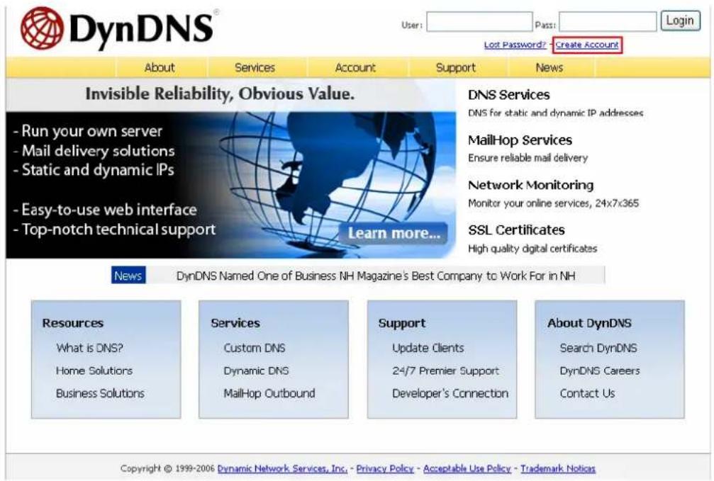
- Enter the information required to register the account.

- Accept the terms of service.
Terms of Service
Please read the acceptable use policy (AUP) and accept it prior to creating your account. Also acknowledge that you may only have one (1) free account, and that creation of multiple free accounts will result in the deletion of all of your accounts.

- Configure the mailing lists if necessary. Then click "Create Account".
Mailing Lists (optional)
DynDNS maintains a number of mailing lists designed to keep our users informed about product announcements, client development, our company newsletter, and our system status. Please use the checkboxes below to alter your subscription preference. Your subscription preference may be changed at any time through the account settings page.
Next Step
After you click "Create Account", we will create your account and send you an e-mail to the address you provided. Please follow the instructions in that e-mail to confirm your account. You will need to confirm your account within 48 hours or we will automatically delete your account. (This helps prevent unwanted robots on our systems)
Create Account
- When your account has been successfully created, a confirmation email will be sent to you. Follow the instructions in the email to activate your account. When you have finished the confirmation process, you can apply for your own dynamic domain name. Please refer to the website of the DDNS provider for more information.
Appendix B Configuration Examples
Environment 1: VioStor, the IP camera, and the monitoring PC are all on the same network
![graph TD A["IP Camera"] --> B["VioStor NVR"] B --> C["LAN"] C --> D["Camera Module"] style A fill:#f9f,stroke:#333 style B fill:#ccf,stroke:#333 style C fill:#cfc,stroke:#333 style D fill:#fcc,stroke:#333](/content/2026/06/1279227/images/5bfb2f4e19a89b289cb96e5c152f77a4cb3b133697b42e427f17b1acd58e900e.jpg)
| IP address | |
| VioStor 192.1 | 68.1.1 |
| PC 192.168.1 | .100 |
| Camera 1 192.168.1.101 | |
| Camera 2 192.168.1.102 | |
| Camera 3 192.168.1.103 | |
In the example, add the IP cameras to VioStor by entering the IP addresses of the IP cameras.
Environment 2: VioStor and the IP camera are installed behind the router, while the monitoring PC is located remotely
![graph TD A["VioStor NVR"] -->|LAN| B["Router"] C["IP Camera"] -->|LAN| B D["Home"] -->|Internet| B B -->|Office| E["Server"] style A fill:#f9f,stroke:#333 style C fill:#f9f,stroke:#333 style D fill:#f9f,stroke:#333 style B fill:#ccc,stroke:#333 style E fill:#ccc,stroke:#333](/content/2026/06/1279227/images/4942e01c1082d82edb2f2a7d11d349beb4553755a310f8fdfc4183d21bb3714e.jpg)
| IP address Mapped port on the router | ||
| VioStor 192.168.1.1 8000 | ||
| Camera 1 192.168.1.101 8001 | ||
| Camera 2 192.168.1.102 8002 | ||
| Camera 3 192.168.1.103 8003 | ||
| Router public IP 219.87.144.205 | ||
| PC 10.8.10.100 |
To allow a remote PC to connect to VioStor and the IP cameras, you need to:
Step 1. Set up the port mapping (virtual server) on the router.
| From | Forward |
| 219.87.144.205:8000 | 192.168.1.1:80 |
| 219.87.144.205:8001 | 192.168.1.101:80 |
| 219.87.144.205:8002 | 192.168.1.102:80 |
| 219.87.144.205:8003 | 192.168.1.103:80 |
to
Step 2. Add the IP camera to VioStor by entering the IP address of the IP camera in the "IP Address" settings. Enter the public IP address of the router and the mapped ports of the IP camera in the "WAN IP Address" settings.
Note: When configuring the IP camera, the WAN IP and LAN IP must be entered.
To open FTP (port 21) and SMB (port 445) of VioStor on WAN, configure the following port mapping settings:
| From | Forward |
| 219.87.144.205:21 | 192.168.1.1:21 |
| 219.87.144.205:139 | 192.168.1.1:139 |
| 219.87.144.205:445 | 192.168.1.1:445 |
to
After finishing the above two steps, you can access VioStor over WAN by entering the IP address http://219.87.144.205:8000 in the IE browser. Then login VioStor with the correct user name and password.
If the port specified to VioStor is 80, you can enter http://219.87.144.205 to access VioStor as the default port of HTTP is 80.
Note: If the router does not use a fixed IP, you will need to configure the DDNS settings on the router. Other configurations are the same as above.
Environment 3: VioStor and the IP camera are all located remotely
![graph TD A["VioStor NVR"] --> B["IP Cameras"] C["Headquarters"] --> B D["Asian Office"] --> B E["American Office"] --> B B --> F["Internet or VPN"]](/content/2026/06/1279227/images/052043acd6a6254ccbb5bc1d917b765bc8f5f712b73982839a24df7553c5045d.jpg)
| IP address | |
| VioStor 219.87.144.205 | |
| Camera 1 61.62.100.101 | |
| Camera 2 61.62.100.102 | |
| Camera 3 61.62.100.103 | |
In this example, add the IP camera to VioStor by adding its IP address to the "IP Address" settings.
Note: If a particular port is assigned to connect to the IP camera, specify the port in the system configuration.
Environment 4: VioStor and the IP camera are installed behind the router
| IP address | |
| VioStor 1 192.168.1.101 | |
| VioStor 2 192.168.1.102 | |
| VioStor 3 192.168.1.103 | |
| Router public IP 219.87.1 | 45.205 |
In the example, to allow a remote PC to access each VioStor by FTP, you need to:
Step 1. Set up the port mapping (virtual server) on the router
| From | Forward | ||
| VioStor 1 219.87 | 145.205:2001 | 192.168.1. | 101:21 |
| VioStor 2 219.87 | 145.205:2002 | 192.168.1. | 102:21 |
| VioStor 3 219.87 | 145.205:2003 | 192.168.1. | 103:21 |
You can connect to VioStor 1 by ftp://219.87.145.205:2001
You can connect to VioStor 2 by ftp://219.87.145.205:2002
You can connect to VioStor 3 by ftp://219.87.145.205:2003
Step 2. Enable FTP port mapping on VioStor
To connect to each VioStor via FTP by clicking "FTP" on the playback page of each VioStor, enable FTP port mapping in "Network Settings" > "File Services" on the system administration page and set the mapped port number.
| Mapped port | |
| VioStor 1 2001 | |
| VioStor 2 2002 | |
| VioStor 3 2003 |
After finishing the above two steps, you can access VioStor via FTP by entering the IP address in the IE browser or clicking "FTP" on the playback page. Then login VioStor by the correct user name and password.
Technical Support
QNAP provides dedicated online support and customer service via instant messenger. You can contact us by the following means:
Online Support: http://www.qnapsecurity.com/onlinesupport.asp
MSN: q.support@hotmail.com
Skype: qnapskype
Technical Support in the USA and Canada:
Email: q_supportus@qnap.com
TEL: 909-595-2819 ext. 185
Address: 166 University Parkway, Pomona CA 9176
Service Hours: 08:00-17:00 (GMT- 08:00 Pacific Time, Monday to Friday)
GNU GENERAL PUBLIC LICENSE
Version 3, 29 June 2007
Copyright © 2007 Free Software Foundation, Inc. http://fsf.org/
Everyone is permitted to copy and distribute verbatim copies of this license document, but changing it is not allowed.
Preamble
The GNU General Public License is a free, copyleft license for software and other kinds of works.
The licenses for most software and other practical works are designed to take away your freedom to share and change the works. By contrast, the GNU General Public License is intended to guarantee your freedom to share and change all versions of a program--to make sure it remains free software for all its users. We, the Free Software Foundation, use the GNU General Public License for most of our software; it applies also to any other work released this way by its authors. You can apply it to your programs, too.
When we speak of free software, we are referring to freedom, not price. Our General Public Licenses are designed to make sure that you have the freedom to distribute copies of free software (and charge for them if you wish), that you receive source code or can get it if you want it, that you can change the software or use pieces of it in new free programs, and that you know you can do these things.
To protect your rights, we need to prevent others from denying you these rights or asking you to surrender the rights. Therefore, you have certain responsibilities if you distribute copies of the software, or if you modify it: responsibilities to respect the freedom of others.
For example, if you distribute copies of such a program, whether gratis or for a fee, you must pass on to the recipients the same freedoms that you received. You must make sure that they, too, receive or can get the source code. And you must show them these terms so they know their rights.
Developers that use the GNU GPL protect your rights with two steps: (1) assert copyright on the software, and (2) offer you this License giving you legal permission to copy, distribute and/or modify it.
For the developers' and authors' protection, the GPL clearly explains that there is no warranty for this free software. For both users' and authors' sake, the GPL requires that modified versions be marked as changed, so that their problems will not be attributed erroneously to authors of previous versions.
Some devices are designed to deny users access to install or run modified versions of the software inside them, although the manufacturer can do so. This is fundamentally incompatible with the aim of protecting users' freedom to change the software. The systematic pattern of such abuse occurs in the area of products for individuals to use, which is precisely where it is most unacceptable. Therefore, we have designed this version of the GPL to prohibit the practice for those products. If such problems arise substantially in other domains, we stand ready to extend this provision to those domains in future versions of the GPL, as needed to protect the freedom of users.
Finally, every program is threatened constantly by software patents. States should not allow patents to restrict development and use of software on general-purpose computers, but in those that do, we wish to avoid the special danger that patents applied to a free program could make it effectively proprietary. To prevent this, the GPL assures that patents cannot be used to render the program non-free.
The precise terms and conditions for copying, distribution and modification follow.
TERMS AND CONDITIONS
0. Definitions.
"This License" refers to version 3 of the GNU General Public License.
"Copyright" also means copyright-like laws that apply to other kinds of works, such as semiconductor masks.
"The Program" refers to any copyrightable work licensed under this License. Each licensee is addressed as "you". "Licensees" and "recipients" may be individuals or organizations.
To "modify" a work means to copy from or adapt all or part of the work in a fashion requiring copyright permission, other than the making of an exact copy. The resulting work is called a "modified version" of the earlier work or a work "based on" the earlier work.
A "covered work" means either the unmodified Program or a work based on the Program.
To "propagate" a work means to do anything with it that, without permission, would make you directly or secondarily liable for infringement under applicable copyright law, except executing it on a computer or modifying a private copy. Propagation includes copying, distribution (with or without modification), making available to the public, and in some countries other activities as well.
To "convey" a work means any kind of propagation that enables other parties to make or receive copies. Mere interaction with a user through a computer network, with no transfer of a copy, is not conveying.
An interactive user interface displays "Appropriate Legal Notices" to the extent that it includes a convenient and prominently visible feature that (1) displays an appropriate copyright notice, and (2) tells the user that there is no warranty for the work (except to the extent that warranties are provided), that licensees may convey the work under this License, and how to view a copy of this License. If the interface presents a list of user commands or options, such as a menu, a prominent item in the list meets this criterion.
1. Source Code.
The "source code" for a work means the preferred form of the work for making modifications to it. "Object code" means any non-source form of a work.
A "Standard Interface" means an interface that either is an official standard defined by a recognized standards body, or, in the case of interfaces specified for a particular programming language, one that is widely used among developers working in that language.
The "System Libraries" of an executable work include anything, other than the work as a whole, that (a) is included in the normal form of packaging a Major Component, but which is not part of that Major Component, and (b) serves only to enable use of
the work with that Major Component, or to implement a Standard Interface for which an implementation is available to the public in source code form. A "Major Component", in this context, means a major essential component (kernel, window system, and so on) of the specific operating system (if any) on which the executable work runs, or a compiler used to produce the work, or an object code interpreter used to run it.
The "Corresponding Source" for a work in object code form means all the source code needed to generate, install, and (for an executable work) run the object code and to modify the work, including scripts to control those activities. However, it does not include the work's System Libraries, or general-purpose tools or generally available free programs which are used unmodified in performing those activities but which are not part of the work. For example, Corresponding Source includes interface definition files associated with source files for the work, and the source code for shared libraries and dynamically linked subprograms that the work is specifically designed to require, such as by intimate data communication or control flow between those subprograms and other parts of the work.
The Corresponding Source need not include anything that users can regenerate automatically from other parts of the Corresponding Source.
The Corresponding Source for a work in source code form is that same work.
2. Basic Permissions.
All rights granted under this License are granted for the term of copyright on the Program, and are irrevocable provided the stated conditions are met. This License explicitly affirms your unlimited permission to run the unmodified Program. The output from running a covered work is covered by this License only if the output, given its content, constitutes a covered work. This License acknowledges your rights of fair use or other equivalent, as provided by copyright law.
You may make, run and propagate covered works that you do not convey, without conditions so long as your license otherwise remains in force. You may convey covered works to others for the sole purpose of having them make modifications exclusively for you, or provide you with facilities for running those works, provided that you comply with the terms of this License in conveying all material for which you do not control copyright. Those thus making or running the covered works for you must do so exclusively on your behalf, under your direction and control, on
terms that prohibit them from making any copies of your copyrighted material outside their relationship with you.
Conveying under any other circumstances is permitted solely under the conditions stated below. Sublicensing is not allowed; section 10 makes it unnecessary.
- Protecting Users' Legal Rights From Anti-Circumvention Law.
No covered work shall be deemed part of an effective technological measure under any applicable law fulfilling obligations under article 11 of the WIPO copyright treaty adopted on 20 December 1996, or similar laws prohibiting or restricting circumvention of such measures.
When you convey a covered work, you waive any legal power to forbid circumvention of technological measures to the extent such circumvention is effected by exercising rights under this License with respect to the covered work, and you disclaim any intention to limit operation or modification of the work as a means of enforcing, against the work's users, your or third parties' legal rights to forbid circumvention of technological measures.
- Conveying Verbatim Copies.
You may convey verbatim copies of the Program's source code as you receive it, in any medium, provided that you conspicuously and appropriately publish on each copy an appropriate copyright notice; keep intact all notices stating that this License and any non-permissive terms added in accord with section 7 apply to the code; keep intact all notices of the absence of any warranty; and give all recipients a copy of this License along with the Program.
You may charge any price or no price for each copy that you convey, and you may offer support or warranty protection for a fee.
- Conveying Modified Source Versions.
You may convey a work based on the Program, or the modifications to produce it from the Program, in the form of source code under the terms of section 4, provided that you also meet all of these conditions:
a) The work must carry prominent notices stating that you modified it, and giving a relevant date.
b) The work must carry prominent notices stating that it is released under this
License and any conditions added under section 7. This requirement modifies the requirement in section 4 to "keep intact all notices".
c) You must license the entire work, as a whole, under this License to anyone who comes into possession of a copy. This License will therefore apply, along with any applicable section 7 additional terms, to the whole of the work, and all its parts, regardless of how they are packaged. This License gives no permission to license the work in any other way, but it does not invalidate such permission if you have separately received it.
d) If the work has interactive user interfaces, each must display Appropriate Legal Notices; however, if the Program has interactive interfaces that do not display Appropriate Legal Notices, your work need not make them do so.
A compilation of a covered work with other separate and independent works, which are not by their nature extensions of the covered work, and which are not combined with it such as to form a larger program, in or on a volume of a storage or distribution medium, is called an “aggregate” if the compilation and its resulting copyright are not used to limit the access or legal rights of the compilation's users beyond what the individual works permit. Inclusion of a covered work in an aggregate does not cause this License to apply to the other parts of the aggregate.
6. Conveying Non-Source Forms.
You may convey a covered work in object code form under the terms of sections 4 and 5, provided that you also convey the machine-readable Corresponding Source under the terms of this License, in one of these ways:
a) Convey the object code in, or embodied in, a physical product (including a physical distribution medium), accompanied by the Corresponding Source fixed on a durable physical medium customarily used for software interchange.
b) Convey the object code in, or embodied in, a physical product (including a physical distribution medium), accompanied by a written offer, valid for at least three years and valid for as long as you offer spare parts or customer support for that product model, to give anyone who possesses the object code either (1) a copy of the Corresponding Source for all the software in the product that is covered by this License, on a durable physical medium customarily used for software interchange, for a price no more than your reasonable cost of physically performing this conveying of source, or (2) access to copy the Corresponding Source from a network server at no charge.
c) Convey individual copies of the object code with a copy of the written offer to provide the Corresponding Source. This alternative is allowed only occasionally and
noncommercially, and only if you received the object code with such an offer, in accord with subsection 6b.
d) Convey the object code by offering access from a designated place (gratis or for a charge), and offer equivalent access to the Corresponding Source in the same way through the same place at no further charge. You need not require recipients to copy the Corresponding Source along with the object code. If the place to copy the object code is a network server, the Corresponding Source may be on a different server (operated by you or a third party) that supports equivalent copying facilities, provided you maintain clear directions next to the object code saying where to find the Corresponding Source. Regardless of what server hosts the Corresponding Source, you remain obligated to ensure that it is available for as long as needed to satisfy these requirements.
e) Convey the object code using peer-to-peer transmission, provided you inform other peers where the object code and Corresponding Source of the work are being offered to the general public at no charge under subsection 6d.
A separable portion of the object code, whose source code is excluded from the Corresponding Source as a System Library, need not be included in conveying the object code work.
A "User Product" is either (1) a "consumer product", which means any tangible personal property which is normally used for personal, family, or household purposes, or (2) anything designed or sold for incorporation into a dwelling. In determining whether a product is a consumer product, doubtful cases shall be resolved in favor of coverage. For a particular product received by a particular user, "normally used" refers to a typical or common use of that class of product, regardless of the status of the particular user or of the way in which the particular user actually uses, or expects or is expected to use, the product. A product is a consumer product regardless of whether the product has substantial commercial, industrial or non-consumer uses, unless such uses represent the only significant mode of use of the product.
"Installation Information" for a User Product means any methods, procedures, authorization keys, or other information required to install and execute modified versions of a covered work in that User Product from a modified version of its Corresponding Source. The information must suffice to ensure that the continued functioning of the modified object code is in no case prevented or interfered with solely because modification has been made.
If you convey an object code work under this section in, or with, or specifically for use in, a User Product, and the conveying occurs as part of a transaction in which the right of possession and use of the User Product is transferred to the recipient in perpetuity or for a fixed term (regardless of how the transaction is characterized), the Corresponding Source conveyed under this section must be accompanied by the Installation Information. But this requirement does not apply if neither you nor any third party retains the ability to install modified object code on the User Product (for example, the work has been installed in ROM).
The requirement to provide Installation Information does not include a requirement to continue to provide support service, warranty, or updates for a work that has been modified or installed by the recipient, or for the User Product in which it has been modified or installed. Access to a network may be denied when the modification itself materially and adversely affects the operation of the network or violates the rules and protocols for communication across the network.
Corresponding Source conveyed, and Installation Information provided, in accord with this section must be in a format that is publicly documented (and with an implementation available to the public in source code form), and must require no special password or key for unpacking, reading or copying.
7. Additional Terms.
"Additional permissions" are terms that supplement the terms of this License by making exceptions from one or more of its conditions. Additional permissions that are applicable to the entire Program shall be treated as though they were included in this License, to the extent that they are valid under applicable law. If additional permissions apply only to part of the Program, that part may be used separately under those permissions, but the entire Program remains governed by this License without regard to the additional permissions.
When you convey a copy of a covered work, you may at your option remove any additional permissions from that copy, or from any part of it. (Additional permissions may be written to require their own removal in certain cases when you modify the work.) You may place additional permissions on material, added by you to a covered work, for which you have or can give appropriate copyright permission.
Notwithstanding any other provision of this License, for material you add to a covered work, you may (if authorized by the copyright holders of that material)
supplement the terms of this License with terms:
a) Disclaiming warranty or limiting liability differently from the terms of sections 15 and 16 of this License; or
b) Requiring preservation of specified reasonable legal notices or author attributions in that material or in the Appropriate Legal Notices displayed by works containing it; or
c) Prohibiting misrepresentation of the origin of that material, or requiring that modified versions of such material be marked in reasonable ways as different from the original version; or
d) Limiting the use for publicity purposes of names of licensors or authors of the material; or
e) Declining to grant rights under trademark law for use of some trade names, trademarks, or service marks; or
f) Requiring indemnification of licensors and authors of that material by anyone who conveys the material (or modified versions of it) with contractual assumptions of liability to the recipient, for any liability that these contractual assumptions directly impose on those licensors and authors.
All other non-permissive additional terms are considered "further restrictions"
within the meaning of section 10. If the Program as you received it, or any part of it, contains a notice stating that it is governed by this License along with a term that is a further restriction, you may remove that term. If a license document contains a further restriction but permits relicensing or conveying under this License, you may add to a covered work material governed by the terms of that license document, provided that the further restriction does not survive such relicensing or conveying.
If you add terms to a covered work in accord with this section, you must place, in the relevant source files, a statement of the additional terms that apply to those files, or a notice indicating where to find the applicable terms.
Additional terms, permissive or non-permissive, may be stated in the form of a separately written license, or stated as exceptions; the above requirements apply either way.
8. Termination.
You may not propagate or modify a covered work except as expressly provided under this License. Any attempt otherwise to propagate or modify it is void, and will automatically terminate your rights under this License (including any patent
licenses granted under the third paragraph of section 11).
However, if you cease all violation of this License, then your license from a particular copyright holder is reinstated (a) provisionally, unless and until the copyright holder explicitly and finally terminates your license, and (b) permanently, if the copyright holder fails to notify you of the violation by some reasonable means prior to 60 days after the cessation.
Moreover, your license from a particular copyright holder is reinstated permanently if the copyright holder notifies you of the violation by some reasonable means, this is the first time you have received notice of violation of this License (for any work) from that copyright holder, and you cure the violation prior to 30 days after your receipt of the notice.
Termination of your rights under this section does not terminate the licenses of parties who have received copies or rights from you under this License. If your rights have been terminated and not permanently reinstated, you do not qualify to receive new licenses for the same material under section 10.
9. Acceptance Not Required for Having Copies.
You are not required to accept this License in order to receive or run a copy of the Program. Ancillary propagation of a covered work occurring solely as a consequence of using peer-to-peer transmission to receive a copy likewise does not require acceptance. However, nothing other than this License grants you permission to propagate or modify any covered work. These actions infringe copyright if you do not accept this License. Therefore, by modifying or propagating a covered work, you indicate your acceptance of this License to do so.
10. Automatic Licensing of Downstream Recipients.
Each time you convey a covered work, the recipient automatically receives a license from the original licensors, to run, modify and propagate that work, subject to this License. You are not responsible for enforcing compliance by third parties with this License.
An "entity transaction" is a transaction transferring control of an organization, or substantially all assets of one, or subdividing an organization, or merging organizations. If propagation of a covered work results from an entity transaction, each party to that transaction who receives a copy of the work also receives
whatever licenses to the work the party's predecessor in interest had or could give under the previous paragraph, plus a right to possession of the Corresponding Source of the work from the predecessor in interest, if the predecessor has it or can get it with reasonable efforts.
You may not impose any further restrictions on the exercise of the rights granted or affirmed under this License. For example, you may not impose a license fee, royalty, or other charge for exercise of rights granted under this License, and you may not initiate litigation (including a cross-claim or counterclaim in a lawsuit) alleging that any patent claim is infringed by making, using, selling, offering for sale, or importing the Program or any portion of it.
11. Patents.
A "contributor" is a copyright holder who authorizes use under this License of the Program or a work on which the Program is based. The work thus licensed is called the contributor's "contributor version".
A contributor's "essential patent claims" are all patent claims owned or controlled by the contributor, whether already acquired or hereafter acquired, that would be infringed by some manner, permitted by this License, of making, using, or selling its contributor version, but do not include claims that would be infringed only as a consequence of further modification of the contributor version. For purposes of this definition, "control" includes the right to grant patent sublicenses in a manner consistent with the requirements of this License.
Each contributor grants you a non-exclusive, worldwide, royalty-free patent license under the contributor's essential patent claims, to make, use, sell, offer for sale, import and otherwise run, modify and propagate the contents of its contributor version.
In the following three paragraphs, a "patent license" is any express agreement or commitment, however denominated, not to enforce a patent (such as an express permission to practice a patent or covenant not to sue for patent infringement). To "grant" such a patent license to a party means to make such an agreement or commitment not to enforce a patent against the party.
If you convey a covered work, knowingly relying on a patent license, and the Corresponding Source of the work is not available for anyone to copy, free of charge
and under the terms of this License, through a publicly available network server or other readily accessible means, then you must either (1) cause the Corresponding Source to be so available, or (2) arrange to deprive yourself of the benefit of the patent license for this particular work, or (3) arrange, in a manner consistent with the requirements of this License, to extend the patent license to downstream recipients. "Knowingly relying" means you have actual knowledge that, but for the patent license, your conveying the covered work in a country, or your recipient's use of the covered work in a country, would infringe one or more identifiable patents in that country that you have reason to believe are valid.
If, pursuant to or in connection with a single transaction or arrangement, you convey, or propagate by procuring conveyance of, a covered work, and grant a patent license to some of the parties receiving the covered work authorizing them to use, propagate, modify or convey a specific copy of the covered work, then the patent license you grant is automatically extended to all recipients of the covered work and works based on it.
A patent license is “discriminatory” if it does not include within the scope of its coverage, prohibits the exercise of, or is conditioned on the non-exercise of one or more of the rights that are specifically granted under this License. You may not convey a covered work if you are a party to an arrangement with a third party that is in the business of distributing software, under which you make payment to the third party based on the extent of your activity of conveying the work, and under which the third party grants, to any of the parties who would receive the covered work from you, a discriminatory patent license (a) in connection with copies of the covered work conveyed by you (or copies made from those copies), or (b) primarily for and in connection with specific products or compilations that contain the covered work, unless you entered into that arrangement, or that patent license was granted, prior to 28 March 2007.
Nothing in this License shall be construed as excluding or limiting any implied license or other defenses to infringement that may otherwise be available to you under applicable patent law.
12. No Surrender of Others' Freedom.
If conditions are imposed on you (whether by court order, agreement or otherwise) that contradict the conditions of this License, they do not excuse you from the conditions of this License. If you cannot convey a covered work so as to satisfy
simultaneously your obligations under this License and any other pertinent obligations, then as a consequence you may not convey it at all. For example, if you agree to terms that obligate you to collect a royalty for further conveying from those to whom you convey the Program, the only way you could satisfy both those terms and this License would be to refrain entirely from conveying the Program.
13. Use with the GNU Affero General Public License.
Notwithstanding any other provision of this License, you have permission to link or combine any covered work with a work licensed under version 3 of the GNU Affero General Public License into a single combined work, and to convey the resulting work. The terms of this License will continue to apply to the part which is the covered work, but the special requirements of the GNU Affero General Public License, section 13, concerning interaction through a network will apply to the combination as such.
14. Revised Versions of this License.
The Free Software Foundation may publish revised and/or new versions of the GNU General Public License from time to time. Such new versions will be similar in spirit to the present version, but may differ in detail to address new problems or concerns.
Each version is given a distinguishing version number. If the Program specifies that a certain numbered version of the GNU General Public License "or any later version" applies to it, you have the option of following the terms and conditions either of that numbered version or of any later version published by the Free Software Foundation. If the Program does not specify a version number of the GNU General Public License, you may choose any version ever published by the Free Software Foundation.
If the Program specifies that a proxy can decide which future versions of the GNU General Public License can be used, that proxy's public statement of acceptance of a version permanently authorizes you to choose that version for the Program.
Later license versions may give you additional or different permissions. However, no additional obligations are imposed on any author or copyright holder as a result of your choosing to follow a later version.
15. Disclaimer of Warranty.
THERE IS NO WARRANTY FOR THE PROGRAM, TO THE EXTENT PERMITTED BY APPLICABLE LAW. EXCEPT WHEN OTHERWISE STATED IN WRITING THE
COPYRIGHT HOLDERS AND/OR OTHER PARTIES PROVIDE THE PROGRAM "AS IS" WITHOUT WARRANTY OF ANY KIND, EITHER EXPRESSED OR IMPLIED, INCLUDING, BUT NOT LIMITED TO, THE IMPLIED WARRANTIES OF MERCHANTABILITY AND FITNESS FOR A PARTICULAR PURPOSE. THE ENTIRE RISK AS TO THE QUALITY AND PERFORMANCE OF THE PROGRAM IS WITH YOU. SHOULD THE PROGRAM PROVE DEFECTIVE, YOU ASSUME THE COST OF ALL NECESSARY SERVICING, REPAIR OR CORRECTION.
16. Limitation of Liability.
IN NO EVENT UNLESS REQUIRED BY APPLICABLE LAW OR AGREED TO IN WRITING WILL ANY COPYRIGHT HOLDER, OR ANY OTHER PARTY WHO MODIFIES AND/OR CONVEYS THE PROGRAM AS PERMITTED ABOVE, BE LIABLE TO YOU FOR DAMAGES, INCLUDING ANY GENERAL, SPECIAL, INCIDENTAL OR CONSEQUENTIAL DAMAGES ARISING OUT OF THE USE OR INABILITY TO USE THE PROGRAM (INCLUDING BUT NOT LIMITED TO LOSS OF DATA OR DATA BEING RENDERED INACCURATE OR LOSSES SUSTAINED BY YOU OR THIRD PARTIES OR A FAILURE OF THE PROGRAM TO OPERATE WITH ANY OTHER PROGRAMS), EVEN IF SUCH HOLDER OR OTHER PARTY HAS BEEN ADVISED OF THE POSSIBILITY OF SUCH DAMAGES.
17. Interpretation of Sections 15 and 16.
If the disclaimer of warranty and limitation of liability provided above cannot be given local legal effect according to their terms, reviewing courts shall apply local law that most closely approximates an absolute waiver of all civil liability in connection with the Program, unless a warranty or assumption of liability accompanies a copy of the Program in return for a fee.
END OF TERMS AND CONDITIONS
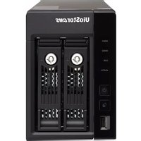
- LEGAL NOTICES
- LIMITED WARRANTY
- CAUTION
- IMPORTANT NOTICE
- REGULATORY NOTICE
- FCC STATEMENT
- CE CE NOTICE
- TABLE OF CONTENTS
- TABLE OF CONTENTS ....5
- SAFETY WARNING....9
- CHAPTER 1. INTRODUCTION....11
- CHAPTER 2. INSTALL VIOSTOR....24
- CHAPTER 3. USE VIOSTOR BY LOCAL DISPLAY....35
- CHAPTER 4. USE VIOSTOR BY WEB-BASED INTERFACE....54
- CHAPTER 5. PLAYBACK THE VIDEO FILES ....70
- 5.1 USE THE WEB-BASED PLAYBACK INTERFACE (VIOSTOR PLAYER) 70
- 5.2 DIGITAL WATERMARKING....95
- 5.3 ACCESS THE RECORDING DATA 100
- CHAPTER 6. SYSTEM ADMINISTRATION....103
- 6.1 QUICK CONFIGURATION....106
- 6.2 SYSTEM SETTINGS....111
- 6.3 NETWORK SETTINGS 114
- 6.4 DEVICE CONFIGURATION....125
- 6.5 USER MANAGEMENT....132
- 6.6 CAMERA SETTINGS....138
- 6.7 SYSTEM TOOLS....164
- 6.8 LOGS & STATISTICS....182
- CHAPTER 7. SYSTEM MAINTENANCE....185
- CHAPTER 8. LCD PANEL....187
- CHAPTER 9. TROUBLESHOOTING....193
- APPENDIX A DYNAMIC DOMAIN NAME REGISTRATION....196
- SAFETY WARNING
- WARNING
- CHAPTER 1. INTRODUCTION
- 1.1 OVERVIEW
- 1.2 HARDWARE ILLUSTRATION
- 1.2.1 VS-8040U-RP/VS-8032U-RP/VS-8024U-RP
- 1.2.2 VS-8040/VS-8032/VS-8024
- 1.2.3 VS-6020 PRO/VS-6016 PRO/VS-6012 PRO
- 1.2.4 VS-5020/VS-5012
- 1.2.5 VS-4016U-RP PRO/VS-4012U-RP PRO/VS-4008U-RP PRO
- 1.2.6 VS-4016 PRO/VS-4012 PRO/VS-4008 PRO
- 1.2.7 VS-4016U-RP
- 1.2.8 VS-2012 PRO/VS-2008 PRO
- 1.2.10 VS-201P/V
- 1.2.11 NVR-104P/V
- 1.2.12 VS-101P/V
- CHAPTER 2. INSTALL VIOSTOR
- 2.1 PERSONAL COMPUTER REQUIREMENTS
- SECURITY SETTINGS OF THE WEB BROWSER
- 2.2 HARD DISK DRIVES COMPATIBILITY LIST
- 2.3 IP CAMERAS COMPATIBILITY LIST
- 2.4 CHECK SYSTEM STATUS
- 2.5 SYSTEM CONFIGURATION
- INSTALL FINDER
- CHAPTER 3. USE VIOSTOR BY LOCAL DISPLAY
- 3.1 QUICK CONFIGURATION
- FINISH
- SYSTEM INITIALIZATION
- 3.2 MONITORING
- EVENT NOTIFICATION
- PTZ CONTROL PANEL
- DISPLAY MODE
- LIVE VIEW SCREEN
- CAMERA STATUS
- CONNECTION MESSAGE
- NOTE
- 3.3 VIDEO PLAYBACK
- PLAYBACK SETTINGS
- CHAPTER 4. USE VIOSTOR BY WEB-BASED INTERFACE
- 4.1 CONNECT TO VIOSTOR
- 4.2 MONITORING PAGE
- 4.2.1 LIVE VIDEO WINDOW
- 4.2.2 DISPLAY MODE
- 4.2.3 PTZ CAMERA CONTROL PANEL
- 4.2.4 MULTI-SERVER MONITORING
- 4.2.5 MONITOR SETTINGS
- VIDEO STREAMING
- VIDEO WINDOWS
- 4.2.6 AUTO CRUISING
- CHAPTER 5. PLAYBACK THE VIDEO FILES
- 5.1 USE THE WEB-BASED PLAYBACK INTERFACE (VIOSTOR PLAYER)
- 5.1.1 CONNECT TO SERVER FOR PLAYBACK
- CLICK "PLAY BY TIME
- TIMELINE SEARCH
- EVENT ENTRY
- 5.1.2 PLAY VIDEO FILES FROM YOUR COMPUTER
- C LICK "ADD FILES
- BROWSE AND SELECT THE FILES
- THE PLAYLIST WILL BE SHOWN. CLICK "PLAY
- 5.1.3 QUAD-VIEW PLAYBACK
- √ DIVIDE THE SELECTED TIME EQUALLY INTO FOUR PLAYBACK WINDOWS
- √ PLAY THE VIDEO OF FOUR IP CAMERAS
- 5.1.4 INTELLIGENT VIDEO ANALYTICS (IVA)
- 5.1.5 CONVERT TO AVI FILE
- 5.2 DIGITAL WATERMARKING
- 5.2.1 EXPORT FILES WITH DIGITAL WATERMARK
- 5.2.2 WATERMARK PROOF
- 5.3 ACCESS THE RECORDING DATA
- 5.3.1 WINDOWS NETWORK NEIGHBOURHOOD (SMB/CIFS)
- 5.3.2 WEB FILE MANAGER (HTTP)
- 5.3.3 FTP SERVER (FTP)
- CHAPTER 6. SYSTEM ADMINISTRATION
- 6.1 QUICK CONFIGURATION
- STEP 3. ENTER THE DATE, TIME, AND TIME ZONE OF THE SERVER
- STEP 4. ENTER THE IP ADDRESS, SUBNET MASK AND DEFAULT GATEWAY OF THE SERVER
- SYSTEM IS INITIALIZING, PLEASE WAIT
- 6.2 SYSTEM SETTINGS
- 6.2.1 SERVER NAME
- 6.2.2 DATE & TIME
- SYNCHRONIZE WITH AN INTERNET TIME SERVER AUTOMATICALLY
- 6.2.3 VIEW SYSTEM SETTINGS
- 6.3 NETWORK SETTINGS
- 6.3.1 TCP/IP CONFIGURATION
- OBTAIN IP ADDRESS SETTINGS AUTOMATICALLY VIA DHCP
- USE STATIC IP ADDRESS
- CONFIGURATION OF NETWORK INTERFACES
- ● FAILOVER (DEFAULT SETTINGS FOR DUAL LAN NVR MODELS)
- FAILOVER
- LOAD BALANCING
- STANDALONE
- ● NETWORK TRANSFER RATE
- PRIMARY DNS SERVER
- SECONDARY DNS SERVER
- ENABLE DHCP SERVER
- 6.3.2 DDNS (DYNAMIC DOMAIN NAME) SERVICE
- 6.3.3 FILE SERVICES
- PASSIVE FTP PORT RANGE
- RESPOND WITH EXTERNAL IP ADDRESS FOR PASSIVE FTP CONNECTION REQUEST
- 6.3.4 HOST ACCESS CONTROL
- ALLOW ALL CONNECTIONS (DEFAULT SETTING)
- ALLOW CONNECTIONS FROM THE LIST ONLY
- DENY CONNECTIONS FROM THE LIST
- 6.3.5 PROTOCOL MANAGEMENT
- 6.3.6 VIEW NETWORK SETTINGS
- 6.4 DEVICE CONFIGURATION
- 6.4.1 SATA DISK
- 6.4.2 RAID MANAGEMENT TOOL
- 6.4.3 USB DISK
- USB DISK
- 6.4.4 UPS
- ENABLE UPS SUPPORT
- UPS MODEL
- IP ADDRESS OF UPS
- 6.5 USER MANAGEMENT
- ADMINISTRATOR
- SYSTEM MANAGER
- USER
- 6.5.1 CREATE USER
- USER NAME
- PASSWORD
- SELECT USER TYPE
- CAMERA ACCESS CONTROL
- 6.5.2 EDIT USER
- 6.5.3 DELETE USER
- 6.5.4 USER ACCESS RIGHTS COMPARISON
- 6.6 CAMERA SETTINGS
- 6.6.1 CAMERA CONFIGURATION
- ADD GENERIC IP CAMERA SUPPORT BY THE CGI COMMAND
- 6.6.2 RECORDING SETTINGS
- 6.6.3 SCHEDULE SETTINGS
- RECORDING SCHEDULE
- 6.6.4 ALARM SETTINGS
- TRADITIONAL MODE
- ALARM SETTINGS
- ADVANCED MODE
- EVENTS
- BUTTONS ON THE EVENT LIST
- ALARM INPUT
- MOTION DETECTION
- ALARM EVENT
- CONNECTION FAILURE
- RECORDING FAILURE (NVR EVENT)
- EXTERNAL EVENT (USER-DEFINED EVENTS)
- EVENT SCHEDULE SETTINGS
- ACTIONS
- EDIT EVENT
- RECORDING
- ADD ACTION
- SELECT ONE OR MORE CHANNELS TO START RECORDING WHEN AN EVENT IS TRIGGERED
- CAMERA CONTROL
- ALARM OUTPUT
- SMS
- BUZZER
- USER-DEFINED ACTION
- 6.6.5 ADVANCED SETTINGS
- 6.7 SYSTEM TOOLS
- 6.7.1 ALERT NOTIFICATION
- 6.7.2 SMSC SETTINGS
- SMSC SETTINGS
- [SMS SERVER SETTINGS]
- [SMS NOTIFICATION SETTINGS]
- 6.7.3 RESTART/SHUT DOWN
- 6.7.4 HARDWARE SETTINGS
- ENABLE THE CONFIGURATION RESET SWITCH
- ● AUTO POWER ON WHEN POWER RESUMES AFTER POWER LOSS
- ENABLE FRONT VIDEO BACKUP BUTTON
- ENABLE LIGHT SIGNAL ALERT WHEN THE FREE SIZE OF SATA DISK IS LESS THAN THE VALUE
- ENABLE ALARM BUZZER
- ● ENABLE REDUNDANT POWER SUPPLY MODE
- 6.7.5 SYSTEM UPDATE
- SYSTEM UPDATE
- 6.7.6 BACKUP/RESTORE/RESET SETTINGS
- BACKUP/ RESTORE/ RESET SETTINGS
- 6.7.7 REMOTE REPLICATION
- ENABLE REMOTE REPLICATION (SUPPORT MULTIPLE CHOICES)
- CONFIGURE YOUR REMOTE STORAGE SERVER
- CONFIGURE THE REMOTE REPLICATION SCHEDULE
- √ REPLICATION SCHEDULE
- SELECT THE BACKUP OPTIONS
- 6.7.8 HARD DISK SMART
- 6.7.9 E-MAP
- 6.7.10 PING TEST
- 6.7.11 ADVANCED SYSTEM SETTINGS
- 6.8 LOGS & STATISTICS
- 6.8.1 SYSTEM EVENT LOGS
- 6.8.2 SURVEILLANCE LOGS
- 6.8.3 ON-LINE USERS LIST
- 6.8.4 HISTORICAL USERS LIST
- 6.8.5 SYSTEM CONNECTION LOGS
- 6.8.6 SYSTEM INFORMATION
- CHAPTER 7. SYSTEM MAINTENANCE
- 7.1 RESET THE ADMINISTRATOR PASSWORD AND NETWORK SETTINGS
- 7.2 POWER OUTAGE OR ABNORMAL SHUTDOWN
- 7.3 HOT SWAPPING HARD DISK DRIVES (RAID CONFIGURATION)
- CHAPTER 8. LCD PANEL
- VIEW THE SYSTEM INFORMATION BY THE LCD PANEL
- TCP/IP
- PHYSICAL DISK
- VOLUME
- SYSTEM
- SHUT DOWN
- REBOOT
- BACK
- SYSTEM MESSAGES
- CHAPTER 9. TROUBLESHOOTING
- THE MONITORING SCREEN DID NOT DISPLAY
- A CHANNEL ON THE MONITORING PAGE CANNOT BE DISPLAYED
- THE RECORDING IS NOT WORKING PROPERLY
- I CANNOT LOGIN THE ADMINISTRATION PAGE OF VIOSTOR
- THE LIVE VIDEO IS NOT CLEAR OR SMOOTH SOMETIMES
- THE ALARM RECORDING DOES NOT FUNCTION
- THE ESTIMATED STORAGE SPACE FOR RECORDING DISPLAYED ON THE "RECORDING SETTINGS" PAGE IS DIFFERENT FROM THE ACTUAL VALUE
- THE MONITORING SCREEN SHOWS HORIZONTAL LINES WHEN THE RESOLUTION OF PANASONIC BB-HCM381 CAMERA IS SET AS 640X480
- THE E-MAP CANNOT BE DISPLAYED CORRECTLY
- I CANNOT FIND VIOSTOR BY THE QNAP FINDER
- THE CHANGES TO THE SYSTEM CONFIGURATION DID NOT TAKE EFFECT
- THE MONITORING PAGE CANNOT BE FULLY DISPLAYED IN INTERNET EXPLORER
- I CANNOT USE THE SMB, FTP, AND WEB FILE MANAGER SERVICES OF VIOSTOR
- VIOSTOR TAKES TOO LONG TO RESTART
- APPENDIX A DYNAMIC DOMAIN NAME REGISTRATION
- REGISTRATION PROCEDURE
- TERMS OF SERVICE
- APPENDIX B CONFIGURATION EXAMPLES
- ENVIRONMENT 4: VIOSTOR AND THE IP CAMERA ARE INSTALLED BEHIND THE ROUTER
- STEP 2. ENABLE FTP PORT MAPPING ON VIOSTOR
- TECHNICAL SUPPORT
- TECHNICAL SUPPORT IN THE USA AND CANADA
- GNU GENERAL PUBLIC LICENSE
- PREAMBLE
- TERMS AND CONDITIONS
- DEFINITIONS
- SOURCE CODE
- BASIC PERMISSIONS
- CONVEYING NON-SOURCE FORMS
- ADDITIONAL TERMS
- TERMINATION
- ACCEPTANCE NOT REQUIRED FOR HAVING COPIES
- AUTOMATIC LICENSING OF DOWNSTREAM RECIPIENTS
- PATENTS
- NO SURRENDER OF OTHERS' FREEDOM
- USE WITH THE GNU AFFERO GENERAL PUBLIC LICENSE
- REVISED VERSIONS OF THIS LICENSE
- DISCLAIMER OF WARRANTY
- LIMITATION OF LIABILITY
- INTERPRETATION OF SECTIONS 15 AND 16
Brand : QNAP
Model : VS-5012
Category : Server