
DJX 480 PK - Mixer SCOTT - Free user manual and instructions
Find the device manual for free DJX 480 PK SCOTT in PDF.


| Product Type | DJ Mixer |
| Model | DJX 480 PK |
| Brand | Scott |
| Dimensions (W x D x H) | 320 x 240 x 80 mm |
| Weight | 2.5 kg |
| Power Supply | AC adapter 12V / 1A |
| Power Consumption | 12 W |
| Inputs | 2 x Phono/Line (RCA), 2 x Line (RCA), 1 x Microphone (6.35 mm) |
| Outputs | Master (RCA), Booth (RCA), Record (RCA), Headphone (6.35 mm) |
| Frequency Response | 20 Hz - 20 kHz |
| Equalization | 3-band EQ per channel: High, Mid, Low |
| Crossfader | Replaceable, with curve adjustment |
| Effects | Built-in DSP effects: Echo, Flanger, Filter |
| Microphone Section | 2-band EQ, talkover function |
| Headphone Section | Cue switching, volume control, split cue |
| Materials | Metal chassis, plastic front panel |
| Cleaning and Maintenance | Wipe with dry soft cloth; do not use solvents |
| Safety | Do not expose to moisture; use specified power adapter only |
| Spare Parts and Repairability | Replaceable crossfader, knobs, and faders; contact Scott service center |
| Included Accessories | AC adapter, user manual |
Frequently Asked Questions - DJX 480 PK SCOTT
User questions about DJX 480 PK SCOTT
0 question about this device. Answer the ones you know or ask your own.
Ask a new question about this device
Download the instructions for your Mixer in PDF format for free! Find your manual DJX 480 PK - SCOTT and take your electronic device back in hand. On this page are published all the documents necessary for the use of your device. DJX 480 PK by SCOTT.
USER MANUAL DJX 480 PK SCOTT
| 10 | Converse fastening nut | |
| 9 | Bolt | jacket |
| 8 | Bolt | M6×1.6×16 |
| 7 | Bolt | M6×1.0×5 |
| 6 Left side frame 1 | ||
| 5 | Cross | beam |
| 4 | Microphone bear frame | 1 |
| 3 | Right side frame | 1 |
| 2 | Side cover | |
| 1 | Wheel | |
| Serial number | Description | Specification |
DJ-ST assemble sketch
Should you have any questions/doubts on operating the unit, please send an e-mail to djtech@first-audio.com.
16
16
16
12
4
SCOTT
POWERED BY DJ-Tech
DJX 480 PK Professional DJ Mixer

USER MANUAL
CONTENTS
- Features......GB-1
- Safety precautions......GB-2
- Functions
Front panel......GB-4
Rear panel......GB-7
- Parameters
Normal parameters......GB-8
Input parameters......GB-9
Output parameters......GB-9
Polarity of connectors......GB-9
Weight and dimensions......GB-10
- Application......GB-11
FEATURES
★Extremely low noise. Several groups of outputs for connection to different active loudspeakers.
★Extremely low impedance circuit. Professional balance input and output reduce the noise to a very low level.
★High quality parts: 60mm faders make the mixing effect more precise. Solid mechanical design makes the unit reliable.
★Very strict testing for parts and the finished product.
★Multi-channel monitoring: Monitor the live condition of every channel.
★Clear arrangement of controls.
SAFETY PRECAUTIONS


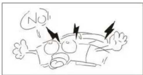
The lightning flash with an arrowhead symbol, within an equilateral triangle, is intended to alert the user to the presence of uninsulated dangerous voltage within the product's enclosure that may be of sufficient magnitude to constitute a risk of electric shock to persons.

The exclamation mark within an equilateral triangle is intended to alert the user to the presence of important operating and maintenance (servicing) instructions in the literature accompanying the appliance.
1
-
Caution: To reduce the risk of electric shock, do not disassemble the appliance. No user-serviceable parts inside. Refer servicing to qualified personnel.
-
Do not install the equipment in a place exposed to direct sunlight.
2

3
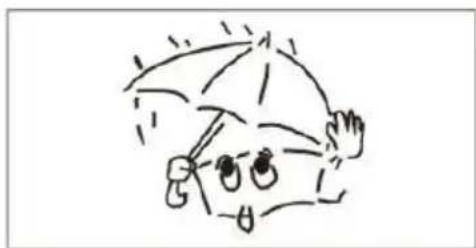
- Do not install the equipment in a dusty, damp or poorly ventilated place.
SAFETY PRECAUTIONS
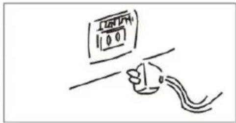
- To prevent damage to the equipment, please unplug from the power outlet if not in use.
4
5

-
To unplug the equipment, always handle the power cord using the plug. Do not unplug out the equipment by pulling the cord.
-
Place the equipment on a stable surface and avoid placing other objects on top of it.
6

7

-
Cleaning: Use a soft, dry cloth for cleaning. For stubborn dirt, soak the cloth in a weak detergent solution; wring well and wipe to remove the dirt. Do not use volatile agents such as benzene or paint thinner, as they may damage the surface finish of the equipment.
-
Please do not block the cooling vents to avoid overheating.
8

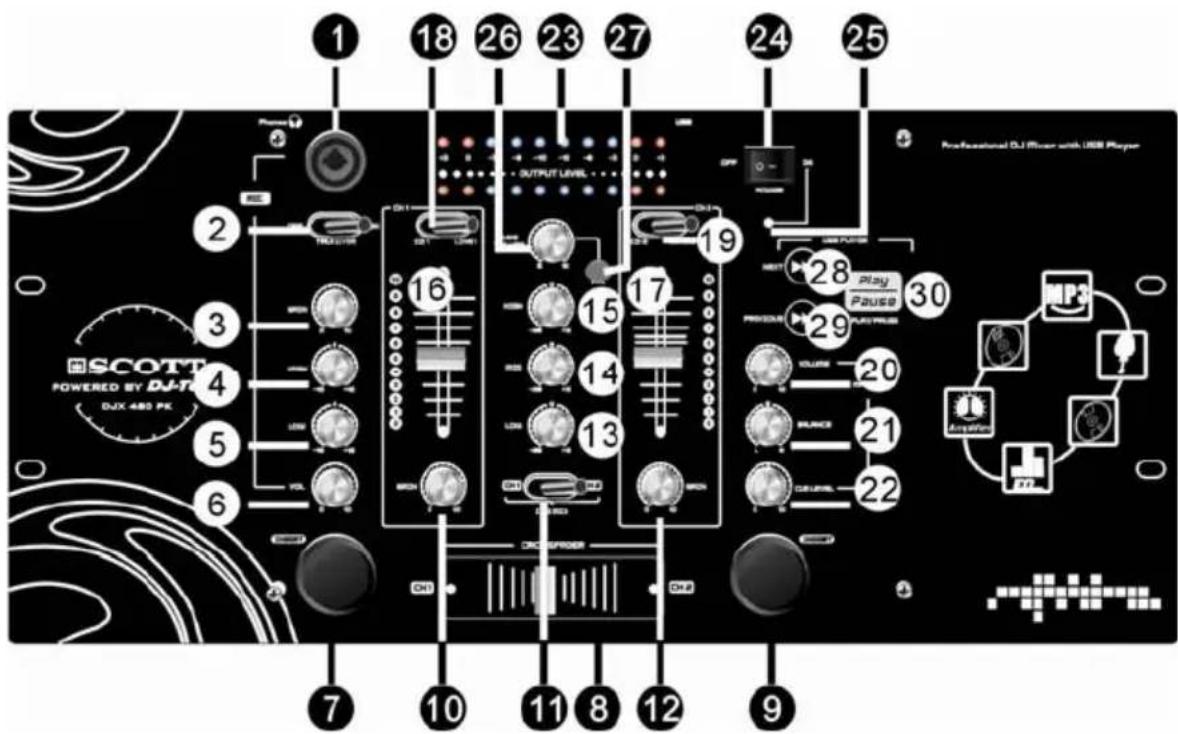
- MICROPHONE input:
XLR + 1/4'' jack combo (balanced and unbalanced). The microphone preamplifier with differential (balanced) input mode provides a clear signal and limits noise.
- TALK OVER switch
Set this switch to “ON” to reduce the volume of channel 1, channel 2 and the USB device, so that the microphone signal stands out. Set this switch to the “OFF” position to switch off this Talk Over function.
- Gain adjustment
This function adjusts the microphone signal. If the signal is too strong, turn the button to the left, and vice versa.
- High frequency gain adjustment
This equipment can increase or reduce signals with a center frequency of 10 KHz by 12dB.
- Low frequency gain adjustment
This equipment can increase or reduce signals with a center frequency of 100 Hz by 12dB.
- Volume control
This dial allows you to precisely control the volume level.
- Left INSERT switch
Hold down this button to force the channel 1 audio signal to be inserted into the general output, regardless of the position of the CROSSFADER control.
- CROSSFADER control switch
This function decreases the signals of the right and left channels.
- Right INSERT switch
Hold down this button to force the channel 2 audio signal to be inserted into the general output, regardless of the position of the CROSSFADER control.
- Gain adjustment
This function allows you to adjust the CD1/LINE1 input signals. If the input signal is too strong, turn the control button to the left, and vice versa.
- Monitor switch
This switch can control the status of signals for CH1 and CH2.
- Gain adjustment
This function allows you to adjust the CD2/LINE2 input signals. If the input signal is too strong, then the control button should be turned to the left, and vice versa.
- Low frequency gain adjustment
Allows you to adjust (+12dB/-26dB) signals with a center frequency of 80Hz.
- Mid frequency gain adjustment
Allows you to adjust (+12dB/-26dB) signals with a center frequency of 1.1KHz.
- High frequency gain adjustment
Allows you to adjust (+12dB/-26dB) signals with a center frequency of 14KHz.
- CH1 control dial
Allows you to have a 30mm linear decrease, and can control the level precisely.
- CH2 control dial
Allows you to have a 30mm linear decrease, and can control the level precisely.
- CD1 and LINE1 selected switch
Select the CD input or line input.
- CD2 and LINE2 selected switch
Select the CD input or line input.
- Main output gain control button
Control the level of main output signals.
- Balance control button
Control the left and right signals.
- Monitor potentiometer
Allows you to adjust the volume of the monitoring channel.
- VU METER
Indicator with lit bars, for a precise visualisation of the output signals.
- Power supply switch
Controls the voltage power of the equipment.
- Power supply indicator light
This lights up when the unit is switched on.
- USB volume control dial
This function allows you to adjust the volume of the USB signal: turn the dial clockwise to increase the volume and counter clockwise to reduce the volume.
- Monitor button
Press this button to monitor the USB signals.
- NEXT button
Select next track.
- Previous button
Select previous track.
- Play/pause button
Allows you to launch play or pause play.

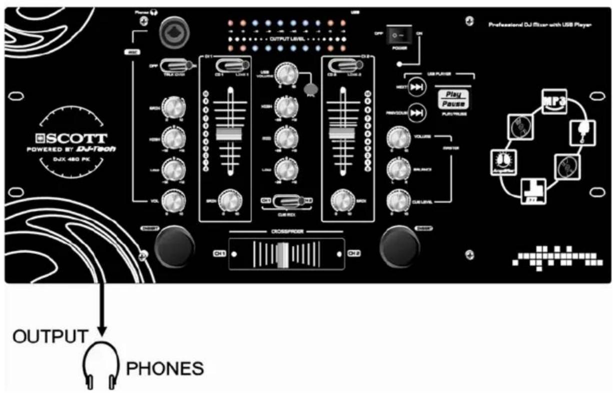
- Headphones output
Sends stereo output signal to headphones.
- CD1 input
Receives all kinds of CD signals (balanced and unbalanced).
- LINE1 socket
Receives all kinds of line signals (balanced and unbalanced).
- CD2 input socket
Receives all kinds of CD signals (balanced and unbalanced).
- LINE2 socket
Receives all kinds of line signals (balanced and unbalanced).
- Record output
Sends the signals to a recorder.
- Mixing output
Sends the mixed signal to main speakers.
- AC voltage input
Connects to an appropriate power supply (refer to the marking on the rear panel).
- Fuse
This protects the electrical circuit of the unit.
- USB port
Allows you to read tracks contained on a USB device.
PARAMETERS
Normal parameters
Voltage Power AC 85V-265V 50/60Hz
Frequency Response....20Hz-20KHz ±0.5dB
Distortion (THD)....0.1% at 20Hz-20KHz +4dB
Distortion (THD).... 0.1% at 20Hz-20KHz +4dB
S/N Ratio....≥80dB
MIC Input Level -40dB (unbalanced)
Line/CD Input Level....0dB (unbalanced)
REC Output Level....4dB (unbalanced)
MIXER Output Level....4dB (unbalanced)
Monitor Output....4dB (unbalanced)
HIGH EQ.... ±12dB
LOW EQ....±12dB
HIGH EQ....+12/-26 dB
MID EQ +12/-26 dB
LOW EQ....+12/-26 dB
INSERT ....Control key
Crossfader....Signal Control
VOICE ONE....Signal Control Switch
Input Impedance 1K (balanced)
Output Impedance....100Ω (unbalanced)
CD/Line ....Select Switch
Phones Signal Select Switch
Separation....≥50dB (1kHz)
Power Source....10W
Input Connector ....RCA with TRS
Output Connector....RCA
PARAMETERS
Input parameters
| Input terminal Input impedance(Ω) | Rated impedance(Ω) | Input level (dB) | |
| CD1 | 10K | 100 | |
| LINE1 10K 100 0/10 | |||
| CD2 | 56K | 100 | |
| LINE2 10K 100 0/10 | |||
| MIC | 1K | 100 | |
Output parameters
| Output terminal Output impedance(Ω) | Rated impedance(Ω) | Output level(dB) | |
| PHONES | 100 | 600 | >10mW |
| REC 100 600 +4 | |||
| MASTER (L/R) | 100 600 +4 | ||
Connector polarity
| MIC INPUT | Tip: hotSleeve: ground |  |
| HEADPHONES | Tip: hot (+)Ring: cold (-)Sleeve: ground | 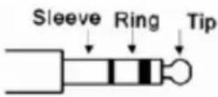 |
| RECORD AND MIX | Tip: hotSleeve: ground | 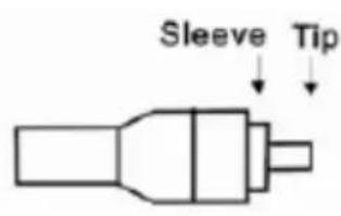 |
PARAMETERS
Weight and dimensions
| MODEL WEIGHT Dimensions (W x D x H) | |
| DJX 480 PK 3,7kg 482 x 220 x 90 mm | |



APPLICATION
![graph TD A["MAIN SPEAKER"] --> B["AMPLIFIER"] C["MAIN SPEAKER"] --> B B --> D["SIGNAL INPUT"] B --> E["OUTPUT"] B --> F["DICTAPHONE OUTPUT"]](/content/2026/06/1279153/images/0595c0e1cf4e13111037de2f9fa332fa3d27b146c52781985d196cad59a67802.jpg)
Disposal of waste electrical & electronic equipment (applicable in the European Union and other European countries with separate collection systems).
This symbol on the product or on its packaging indicates that this product must not be treated as household waste. Instead it must be handed over to the applicable collection point for the recycling of electrical and electronic equipment. By ensuring this product is disposed of correctly, you will help prevent potential negative

consequences for the environment and human health, which could otherwise be caused by inappropriate waste handling of this product. The recycling of materials will help to conserve natural resources. For more detailed information about recycling of this product, please contact your local authorities, your household waste disposal service or the shop where you purchased the product.
Should you have any questions/doubts on operating the unit, please send an e-mail to djtech@first-audio.com.
SCOTT
POWERED BY DJ-Tech
DJX 480 PK / CDX-310
PROFESSIONAL DUAL CD PLAYER


USER MANUAL
www.my-scott.com
PROFESSIONAL DJ DUAL CD PLAYER - USER MANUAL

ENGLISH
| CAUTION | ||
| To prevent electric shock do not disassemble this unit. No user serviceable parts inside. Refer servicing to qualified servicing personnel. | ||
IMPORTANT
Use of controls or adjustments or performance of procedures other than those specified in this manual may result in hazardous radiation exposure.
Professional DJ dual CD player
- 1 bit D/A converter with 8 times oversampling.
- Instant start.
- Pitch display.
• +10 track skip search. - Digital output.
- Pitch range: +/-8%, +/-12%, +/-16%.
- Time elapsed, remaining time or total remaining time display.
- Single/continuous play.
- Relay play allows consecutive playback with two decks.
- Frame search.
- Transport protection.
- Auto cue.
• 20 tracks programmable play.
Use this dial to select the scanning direction and speed. The disc is scanned forwards when the shuttle dial is turned clockwise from the neutral position, and backwards direction when the shuttle dial in turned counter clockwise. The scanning speed increases when the shuttle dial is turned faster.
2. OPEN/CLOSE (OPEN/CLOSE BUTTON)
Press this button once to open or close the disc compartment. The main unit also includes OPEN/CLOSE buttons. The disc compartment cannot be opened during playback, so please stop playback before pressing the button.
3. TIME button
Press this button to switch the time display between the elapsed time and remaining time. "REMAIN" appears on the LCD if you have selected the remaining time.
4. LCD
- TRACK - Shows current track number
- TIME BAR - Shows either time remaining or elapsed depending on the TIME button setting. Starts flashing at the end of each track to alert the user to take action.
- MINUTE - Shows "minutes" time information for the current track.
- SECOND - Shows "seconds" time information for the current track.
- FRAME - Shows "frame" time information of current track.
- "SINGLE" - this appears when the unit is set to play just one track at a time. Otherwise the CD will play continuously through all tracks. This function is controlled by the SGL button.
- "TOTAL", "REMAIN" - indicate whether the time shown on the display is the total remaining time or the remaining time for the current track.
- PITCH - Shows the percentage change in pitch (speed) of the song.

5. SGL (SINGLE BUTTON)
Press this button to select the single or continuous play mode. The "SINGLE" mode is indicated by the SINGLE indicator on the LCD, whereas no indicator appears in continuous play mode.
6. PROG button
Press the PROG button to enter program mode and stop CD playback.
7. PROG INDICATOR
The PROG LED lights up when program mode is set.
8. LOOP INDICATOR
When the LOOP start point is set, the LED flashes. When in LOOP mode, the LED lights up.
9. LOOP (LOOP BUTTON)
Press the LOOP button to set the loop start point, and press the LOOP button again to set the loop end point.
10. PITCH INDICATOR
When the indicator lights up, the pitch adjustment is enabled.
11. JOG (JOG DIAL)
If the dial is turned when a CD is paused, the point at which the sound is being produced moves by a number of frames corresponding to the number of clicks. If you turn it clockwise this moves the point forward, if you turn it counter clockwise this moves the point backwards.
12. ◀ BUTTON
Use this button to go back to the beginning of the current track or select a previous track.
When in CUE mode, the CUE indicator lights up.
14. CUE (CUE BUTTON)
Press the CUE button during playback to return to the position at which playback started.
15. +10 (TRACK +10 BUTTON)
Use this button to skip ahead 10 tracks.
16. PLAY/PAUSE BUTTON
Use this button to start playback. Press once to start playback, twice to set the pause mode, and three times to resume playback.
17. PLAY INDICATOR
The PLAY indicator lights up during play mode.
18. ▶BUTTON
Use these buttons to skip to the next CD track.
19. PITCH BEND - BUTTON
The CD slows down while this button is pressed. Release the button to return to the original BPM.
20. PITCH BEND + BUTTON
The CD speeds up while this button is pressed. Release the button to return to the original BPM.
21. PITCH (PITCH BUTTON)
Press the PITCH button to switch the pitch adjustment on/off. Hold the PITCH button down for more than 0.6 seconds to adjust the playing speed (+/-8% / +/-12% / +/-16%).
22. PITCH SLIDER
Use the slider to adjust the CD pitch. Slide up to decrease the pitch, or down to increase the pitch.
23. CONTROL START SOCKETS
These sockets are designed to connect to a mixing console using a 3.5mm jack plug. This will provide you with remote start capability from your mixing console.
24. CONTROL CONNECTOR
Connect this connector to the “CONNECT TO REMOTE CONTROL” connector on the main unit using the included control cord.
MAIN UNIT:
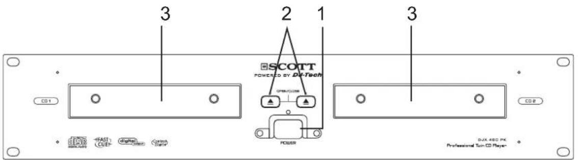
1. POWER (POWER ON/OFF SWITCH)
When the POWER switch is pressed, the power turns on.
2. OPEN/CLOSE BUTTON
Press this button to open and close the disc compartment. The control unit also includes OPEN/CLOSE buttons. The disc compartment cannot be opened during playback, so please stop playback before pressing the button.
3. DISC COMPARTMENT
Place the discs in the disc compartments. Press the OPEN/CLOSE button to open and close the corresponding disc compartment.
4. REMOTE CONTROL CONNECTOR
Connect this connector to the control unit using the included control cord.
5. AUDIO OUT R AND L
The audio signals from each player can be sent to another unit via these jacks.
6. DIGITAL OUT SOCKET
This socket transmits a digital audio signal. Connect the output to the respective input of a digital amplifier for example.
CONNECTIONS:

FUNCTIONS:
Opening & closing the disc compartment.
- Turn the unit power on. Press the OPEN/CLOSE button to open the disc compartment. OPEN/CLOSE buttons are provided on both the main unit and control unit.
- You cannot open the disc compartment when the unit is reading a disc. Push the START / PAUSE button before pushing the OPEN / CLOSE button.
Loading discs
- Hold the disc by the edges and place it in the disc compartment, then press the OPEN/CLOSE button again to close the disc compartment. The unit will show the total number of tracks and the total playing time for about 2 seconds then it will enter cue mode. By default, the cue point will be set to the start of the first track.
Caution:
- Do not place any foreign objects in the disc compartment, and do not place more than one disc in the disc compartment at a time.
- Do not push the disc compartment in manually when the power is off, as this may result in malfunction and damage to the player.
Selecting Tracks
- Press the SKIP («/») button once to move to next or previous track.
- Hold the SKIP (◀/▶) button to change tracks continuously at a higher speed.
- When a new track is selected during playback, playback begins as soon as the skip search operation is completed.
- If the skip button (▶) is pressed while at the last track, the first track is selected. In the same way, if the skip button (◀) is pressed while at the first track, the last track is selected.
Starting playback
- Press the PLAY/PAUSE button during the pause or cue mode to start playback. The PLAY indicator lights up.
- The point at which playback starts is automatically stored in the memory as the cue point. The player then returns to the cue point when the CUE button is pressed. (Back Cue)
![graph LR A["▶"] --> B["▶/II"] B --> C["II"]](/content/2026/06/1279153/images/544d30e27868c800e71eee1d9d351d8101e4643f9a917688a4218f6db4e4910a.jpg)
Figure 4-1
Stopping Playback
There are two ways to stop playback:
- Press the PLAY/PAUSE button during playback to pause at that point.
- Press the CUE button during playback to return to the cue point and enter pause mode.(Back Cue)
![graph TD A["▶"] --> B["▶/II"] B --> C["II"] A <--> D["CUE"] D --> E["II"]](/content/2026/06/1279153/images/b65fa986f605b60ae96b1d6272374ddde78189045fbdbcb156a82e53933a8ab5.jpg)
Figure 5-1
Pausing
- Press the PLAY/PAUSE button to start or pause play.
- The play indicator flashes when the pause mode is set.
- Figure 6-1 shows the relationship between play and pause.
![graph LR 1["1) Step 2"] --> 3["3) Step 6"] 3 --> 5["5) Step 1"] 5 --> 7["7) Step 7"]](/content/2026/06/1279153/images/d1472ece3ce2da55fc930617859baddf79e814d4a5567cd0e2d35e1af2174dbb.jpg)
- The player has completed the cue or pause operation and is waiting for the play start command.
- When the PLAY/PAUSE button is pressed, playback starts and the cue point is stored in the memory.
- Play.
- The pause mode is set when the PLAY/PAUSE button is pressed again
- Pause.
- Playback resumes when the PLAY/PAUSE button is pressed again.
- Play.
Cueing
- "Cueing" is the action of preparing for playback.
- Press the CUE button: the player will enter cue mode. It will return to the cue point and enter pause mode, while the cue indicator lights up and the play indicator flashes. When the PLAY/PAUSE button is pressed, play starts from the cue point.
- When the track search operation is completed after pressing the SKIP (◀/▶) buttons, the player automatically finds the position at which the sound starts and places the cue point there (Auto Cue).
- If the CUE button is pressed after the search operation or the scanning operation, (fast forwards/backwards) the player returns to the cue point and enters pause mode.
– Figure 7-1 shows the relationship between the play and back cue operations.
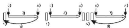
- The player is in cue or pause mode and is waiting for the user to launch playback.
- When the PLAY/PAUSE button is pressed, playback starts and the cue point is stored in the memory.
- Play.
- The pause mode is set when the PLAY/PAUSE button is pressed again.
- Pause.
-
When the PLAY/PAUSE button is pressed again, playback resumes and the new cue point is stored in the memory.
-
Play.
-
Press the CUE button.
-
The player returns to the cue point. (Back Cue)
◆ Cue point setting:
- When play starts after pausing or skipping to a new track using the skip button, the point at which you start playback will become the new cue point.
- When a new cue point is set, the cue indicator light flashes for about 1 second.
NOTE: In cue mode, if the CUE button is pressed and held, playback will start from the cue point. When the button is released, the player will return to the cue mode automatically, and you can check the cue point.
Frame search
- Frame search is a function for monitoring the sound at a certain section of the disc and manually changing the position. Searching is used to set play start points with precision.
- Turn the JOG dial while in pause or cue mode to begin searching. Turn the dial clockwise to go forwards or counter clockwise to go backwards. The point at which the sound starts is indicated on the LCD.
- When the JOG dial is turned, the playback point moves a number of frames corresponding to the number of the clicks, and the time display on the LCD also changes.
- The search point moves forwards when the JOG dial is turned clockwise, and backwards when the JOG dial is turned counter clockwise.
Scanning (Fast forward/Fast backward)
- Scanning is a function for quickly moving forwards or backwards when the SHUTTLE dial is rotated.
- This unit supports 4 different speeds according to the rotating angle of the SHUTTLE dial
- Turn the SHUTTLE dial to begin scanning. The disc moves rapidly forwards or backwards and the sound is emitted. The current scan point is indicated on the LCD.
– Turn the shuttle dial clockwise to scan forwards, counter clockwise to scan backwards.
Time display
- Press TIME button to select the time display mode
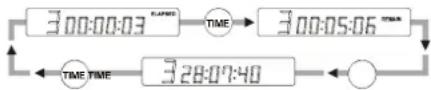
Total remaining time of the disc
Matching the Beats Per Minute (BPM) for two CDs
There are three tools available for matching the BPM of two CDs:
- Use the pitch slider to adjust the BPM.
– Use the PITCH BEND +/- buttons to change the BPM temporarily. - Turn the JOG dial to change the BPM temporarily.
a. Pitch Slider
- To adjust the BPM by sliding the pitch slider up or down, press the PITCH button to turn on the PITCH adjustment function before using.
- Slide the pitch slider up to decrease the BPM, or down to increase the BPM. The adjustment range is +/-8, +/-12, +/-16%.
b. Pitch Bending +/- buttons
■ The BPM increases or decreases respectively when the PITCH BEND+ or PITCH BEND-button is pressed.
The BPM increase depends on how long you hold the button. If you hold the button for about 1/2 second, the BPM will either increase by 16% for PITCH BEND+ or decrease by 16% for PITCH BEND-. If you tap the button quickly, the BPM will only change a little so you can change the beat slightly without audible changes in the music.
■ The CD will return to the tempo indicated by the Pitch slider when you let go of the PITCH BEND+/− button.
Figure 11 shows an example of how to use the pitch bend function. In this example, both players are playing and the BPM of the two CDs does not match. Use the PITCH BEND +/- buttons to adjust the BPM.
![graph LR A["CD 1 bass beat"] --> B["Bass beat"] C["CD 2 bass beat"] --> D["Bass beat"] B --> E["PITCH BEND"] D --> E E --> F["Output"]](/content/2026/06/1279153/images/d3b46a5ae1c83d811f2b48970bc1fa7c25f054534ca514543fd56cfb2cdee1cf.jpg)
c. JOG dial
Turn the jog dial clockwise during play to increase the number of BMP, and turn it counter clockwise to reduce the number of BMP. The faster you turn the wheel, the more the BMP changes. The BMP changes with a range of +/-8, +/-12, +/-16%
When you release jog wheel, the CD will return to the tempo indicated by the pitch slider.
Programmed play
- Press the PROGRAM button, the player will enter the program mode and the CD will stop playing.
- Select the desired track by pressing the SKIP (◀/▶) buttons, then press the PROGRAM button again. The selected track will be added to the program sequence.
- Repeat step 2. A maximum of 20 tracks can be programmed at one time.
- Press the PLAY/PAUSE button to start the program play from the first selection.
- Press the program button ( ▶Ⅱ) again during programmed play to stop play.
- Press and hold the program button more than 2 seconds to cancel the program mode and erase all the current program contents.
Loop Play
- Press the LOOP button to set the loop start point A, the LOOP indicator will flash on the LCD.
- Press the LOOP button again to set the loop end point B, after the B point is set, the playback will enter the loop play from A to B repeatedly.
- Press the LOOP button again, to cancel the loop play function. The LOOP indicator switches off.
Relay Play
- Press the PROG and SGL buttons to activate the relay function. The track number on the LCD will flash.
Fader start
- You have the possibility to start the respective CD-player directly from the mixing console. Make sure that the CONTROL START socket is connected to the respective socket on the mixing console. Additionally, the audio out socket must be connected to the Line-input sockets on your mixing console. Please note that the Fader Start function only works with the appropriate mixing consoles. Insert the CD and select the desired track. Start playback from your mixing console
INSTALLING THE UNIT:
- Place your unit on a flat surface or mount it in a secure rack mount case.
- Be sure the player is mounted in a well-ventilated area where it will not be exposed to direct sunlight, high temperatures, or high humidity
- Try to place the unit as far as possible from TVs and tuners, as the unit may cause undesirable interference
CAUTION
The player will work normally when the main unit is mounted with the front panel at within 15° of the vertical plane. If the unit is tilted excessively, discs may not be loaded or unloaded properly.
The control panel's LCDs are designed to be clearly visible within the angles shown in Figure 2. Mount the control unit so that the visual angle is within this range.

Figure 1
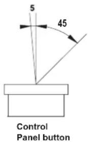
Figure 2
Connections:
- Turn off unit using the POWER switch
- Connect the RCA cable to the input on your mixing console
- Connect the control cords to the "CONNECT TO REMOTE CONTROL" connector on the main unit and to the "CONNECT TO MAIN UNIT" connector on the controller.
CAUTION:
- Be sure to use the supplied mono 1/8" control cables. Using other types of cable may result in unit damage.
- To avoid severe damage to the unit, be sure the power is off before making the connections.
SPECIFICATIONS:
Pitch bend +/-16%
Pitch Range Within +/-8%,+/-12%,+/-16%
Power supply AC115/230V, 60/50Hz
Dimensions Controller: 482 x 88.8 x 97mm
Main unit: 482 x 88.8 x 262.5mm
Weight Controller: 1.74Kg
Main unit: 5.09Kg
Should you have any questions/doubts on operating the unit, please send an e-mail to djtech@first-audio.com.
DISPOSAL:
Disposal of old electrical & electronic equipment (applicable in the European Union and other European countries with separate collection systems).
This symbol on the product or on its packaging indicates that this product must not be treated as household waste. Instead it must be handed over to the relevant collection point for the recycling of electrical and electronic equipment. By ensuring this product is disposed of correctly, you will help prevent potential negative consequences for the environment and human health, which could otherwise be caused by inappropriate handling of this product. The recycling of materials will help to conserve natural resources. For more detailed information about the recycling of this product, please contact your local authorities, your household waste disposal service or the shop where you purchased the product.

SCOTT
POWERED BY DJ-Tech
DJX 480 PK / AX-121
PROFESSIONAL AMPLIFIER

USER MANUAL
CONTENTS
Features......GB-1
Safety Instructions......GB-2
Components and functions
Front Panel ....GB-4
Back Panel......GB-4
System Connections......GB-5
Operation......GB-8
Troubleshooting......GB-9
Technical Specifications......GB-10
FEATURES
◆ Direct connection and differential amplifier distribution
◆ Dynamic bias, balanced amplifier input
◆ Wide bandwidth, low distortion
◆ Loudspeaker protection, overload protection
◆Front panel with electric level control
◆ Normal working/signal/overload protection display
◆Bridged mono mode operation
◆ Unbalanced 6.35 input connector
◆Heavy load, dual Speakon output connector
◆ Time-delay control switch
◆Fan
◆Thick steel surface


The lightning flash with an arrowhead symbol within an equilateral triangle is intended to alert the user to the presence of uninsulated dangerous voltage within the product's enclosure that may be of sufficient magnitude to constitute a risk of electric shock to persons.

The exclamation mark within an equilateral triangle is intended to alert the user to the presence of important operating and maintenance (servicing) instructions in the literature accompanying the appliance.
WARNING: Incorrect use of this appliance can be very dangerous. If children are using this product (or similar products), they must be supervised by adults. Please do not let children dismantle the appliance or touch the power cords.
IMPORTANT WARNING: Do not use this appliance if it may distract you when driving or working.
1

-
Caution: To reduce the risk of electric shock, do not remove cover (or back). No user-serviceable parts inside. Refer servicing to qualified personnel.
-
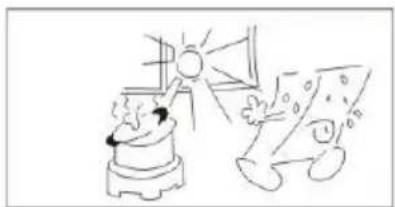
Do not install the equipment in a place exposed to direct sunlight.
2
SAFETY PRECAUTIONS
3

-
Do not install the equipment in a dusty, damp or poorly ventilated place.
-
To prevent damage to the equipment, please unplug from the power outlet if not in use.
4

5

-
To unplug the equipment, always handle the power cord using the plug. Do not pull out the plug by tugging the cord.
-
Place the equipment on a stable surface and avoid placing other objects on top of it.
6

7

-
Cleaning care: Use a soft, dry cloth for cleaning. For stubborn dirt, soak the cloth in a weak detergent solution; wring well and wipe to remove the dirt. Do not use volatile agents such as benzene or paint thinner, as they may damage the surface finish of the equipment
-
Please do not block the cooling vents to avoid overheating.
8

COMPONENTS AND FUNCTIONS
All the components are located on the front or back panel.
FRONT PANEL

- Power switch
- Left channel volume adjust dial
- Left channel overload indicator
- Right channel volume adjust dial
- Right channel overload indicator
REAR PANEL
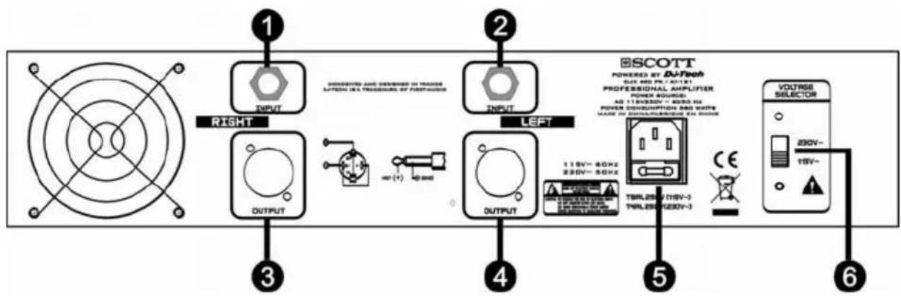
- Right channel unbalanced signal input (INPUT RIGHT)
- Left channel unbalanced signal input (INPUT LEFT)
- Right channel speaker output
- Left channel speaker output
- AC power socket and fuse socket
- Voltage selector
SYSTEM CONNECTIONS
The circuitry in this amplifier has an unbalanced input. According to the diagram below, you can see that the amplifier can be connected to a balanced or unbalanced source. Each channel has an unbalanced input socket (6.3 mm), and the input must be connected to the ground.

XLR signal output connector (balanced signals)
6.3mm three-wire earphones plug (balanced wire input)

XLR output connector (balanced signals)
6.3mm two-wire earphones plug (unbalanced wire input)

RCA output jack (unbalanced signal)
6.3mm two-wire earphones plug (unbalanced wire input)
| Connection | XLR | Jack | RCA |
| Audio Ground Pin 1 Sleeve Sheel | |||
| High (+) Pin 2 Tip Pin | |||
| Low (-) Pin 3 Ring -- |
Use the Speakon jack to connect the amplifier and speakers. Please use a high quality cord to make the connection as shown in the diagram below.

SYSTEM CONNECTION

A
B

C
D
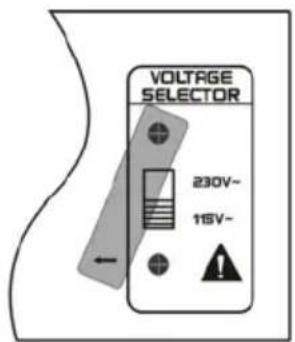
A. Loosen one of the screws.
B. Slide the protection sheet to one side.
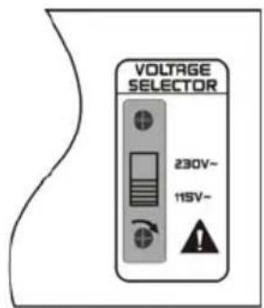
C. Select the required voltage using the switch.
D. Slide the protection sheet back to its original position and tighten the screw.
Note: Do not loosen the two screws at the same time.
Read the previous sections on system connections. Check whether the local power voltage is consistent with the requirements of the unit and whether the unit is turned off before making the connections. In order to avoid injury, use the correct wires. For more details, refer to the illustrations in the previous section.

Speaker impedance must be between 4 ohms and 16 ohms.

After confirming the local power voltage type is consistent with the requirements of the unit, you can connect the power wire.
![graph TD A["MIXER"] -->|RIGHT OUTPUT| B["Right Channel speaker"] A -->|LEFT OUTPUT| C["Left Channel speaker"] B --> D["INPUT"] B --> E["OUTPUT"] C --> F["INPUT"] C --> G["OUTPUT"] D --> H["SCOTT"] E --> I["SCOTT"] F --> J["VOLTURE SELECTOR"] G --> K["VOLTURE SELECTOR"] style A fill:#f9f,stroke:#333…](/content/2026/06/1279153/images/77bba036f53316ef2010035907f106ec179e2d84556f25dacd219ce0580a9629.jpg)
OPERATION
When switching the system on or off, we advise you to switch on the amplifier last and switch it off first so as to prevent any impact caused by the ON/OFF switch.
Check whether the local power voltage the same as the one indicated on the back panel and that all the connections are correct before turning the power on.
Turn the volume adjustment dials for the left and right channels anti-clockwise to the (-∞) position. Before pressing the power supply switch, please switch on the input signal source. After about 3 seconds, when you hear the relay, turn the volume adjustment dial for the left and right channels clockwise to the appropriate volume level. We suggest that you adjust the dial to the maximum (0) position and that you use the external appliance to adjust the volume level.
When using the amplifier, if the overload pilot lamp (OVERLOAD) blinks, this means the equipment is working properly and is safe to use. If the overload pilot lamp (OVERLOAD) no longer blinks, this means the equipment is overloaded. In this case, please turn down the volume until the indicator blinks again. Please carry follow this recommendation in order to avoid damaging the equipment by subjecting it to overload for too long.
About 3 seconds after switching on the equipment, you will hear a muffled sound. If you hear the same sound when using the amplifier, please switch it off then switch it back on again after checking the connections. If the problem persists, please consult a qualified technician or contact our company for maintenance.
TROUBLESHOOTING
Please refer to the table below in order to solve any problems when using the amplifier. If the problem persists, please contact a professional technician or contact our company. Never try to repair the appliance yourself.
| Problem | Possible reason(s) | So |
| No sound 1. | The power plug is in the wrong position.2. The speakers are not connected properly.3. The inputs/outputs are not connected properly.4. Short-circuit of the speaker terminal.5. The volume buttons are adjusted to the minimum. | 1. Connect the power properly.2. Check the connection of the speakers.3. Connect the input/output wire correctly.4. Connect the speakers properly before switching on the unit.5. Adjust the volume level. |
| No sound from one speaker | 1. The speakers are not connected properly.2. Balance or relative electric level is adjusted to one speaker. | 1. Check the speaker connections.2. Adjust the balance or the relative electric level. |
| "Hum" sound; low-frequency noise | The ground is not connected properly. | Reconnect it and check the signal wire. |
| No bass phase-shifting of the loudspeaker | When connecting the speakers, one speaker's anode and cathode are connected in reverse. | Check the connection and connect the anode and cathode properly. |
ution
TECHNICAL SPECIFICATIONS
Rated output for each channel
8 ohms @ 1kHz, 1% THD+N....128 watts RMS per channel
4 ohms @ 1kHz, 1% THD+N....225 watts RMS per channel
S/N Ratio.....>95dB, 22Hz-22kHz bandwidth referenced to rated output
Frequency response....10Hz-20kHz (+0, -0.5dB)
Damping factor....200
Slew rate....60V/μs (two channels)
Input sensitivity......0dB (1V) for rated output with Input control at maximum
Maximum input level....6V
Input impedance....10kΩ Unbalanced
Crosstalk....-85dB, 1kHz
Output shift....+/-50mV, Servo controlled
Power Voltage.....AC110-120V 50/60Hz or AC220-240V 50/60H
Depends on distribution area, please refer to back panel of this unit.
Consumption power
Minimum....9watts
Maximum....580Watts
Dimensions....482mm (W) × 225mm (D) × 100mm (H)
Weight....9.0Kg
Disposal of waste electrical & electronic equipment (applicable in the European Union and other European countries with separate collection systems).
This symbol on the product or on its packaging indicates that this product must not be treated as household waste. Instead it must be handed over to the applicable collection point for the recycling of electrical and electronic equipment. By ensuring this product is disposed of correctly, you will help prevent potential negative consequences for the environment and human health, which could

otherwise be caused by inappropriate waste handling of this product. The recycling of materials will help to conserve natural resources. For more detailed information about recycling of this product, please contact your local authorities, your household waste disposal service or the shop where you purchased the product.
Should you have any questions/doubts on operating the unit, please send an e-mail to djtech@first-audio.com.
SCOTT
POWERED BY DJ-Tech
DJX 480 PK / S - 12
PROFESSIONAL SPEAKER

USER MANUAL
Table Of Contents
Important safety precautions...... GB-2
Features......GB-2
Components......GB-3
Connecting The Speaker System......GB-4
Choosing a power amplifier to connect to the DJX 480 PK......GB-5
Quick Set-Up......GB-6
Installing the DJX 480 PK......GB-7
Technical specifications......GB-8
Important Safety Precautions
- Please read all instructions before operating the unit.
- Keep these instructions for future reference.
- Please pay attention to all safety warnings.
- Follow the manufacturer's instructions.
- Do not use this unit near water or moisture.
- Clean only with a damp cloth.
- Do not install near any heat sources such as radiators, heat registers, stoves, or other apparatus (including amplifiers) that produce heat.
- Prevent the cable from being walked on and tugged, particularly at plugs.
- Unplug this unit during lightning storms or when unused for long periods of time.
- Refer all servicing to qualified personnel. Servicing is required when the unit has been damaged in any way, such as if the plug or wire has been damaged, if water has been spilled into the unit or foreign objects have fallen into it, the unit has been exposed to rain or moisture, it does not operate normally, or it has been dropped.
Features
This loudspeaker system can be used with a variety of live sound applications. With its high quality components, convenient size, ergonomic carry handles and stand mount receptacle, the system will provide great sound and reliability. Here are some of its main features:
- Passive loudspeaker system featuring high quality components and providing clean and clear sound reinforcement for vocal and/or music reproduction in order to obtain a good performance.
- To guarantee deep bass response, this system utilizes custom designed, heavy-duty, low-frequency drive units.
- Two 6.35mm MIC jacks.
- Can be stand mounted thanks to 1.39 inch speaker stand receptacles.
- Solid, high quality design ensures reliable performance night after night and venue after venue.
Components
FRONT PANEL
①HF Driver – the DJX 480 PK uses a piezo driver with a 1" throat.
②Low frequency - Custom designed, heavy-duty, 12" driver providing deep bass.
③Port Tube - Two precision tuned, low frequency port tubes extending the bass response.
④Handle - one handle on the top of the speaker.
⑤Grille - Durable steel grille to protect the driver.
⑥Wood casing with carpet finish.

BACK PANEL
INPUT/EXTENSION: 6.35mm MIC jack connector for connecting to the output of a power amplifier or powered mixer. 6.35mm MIC jack connector for connecting an additional speaker.
Note: For a detailed wiring diagram, see the next page of this manual.
![graph TD A["A"] --> C["Box with circular elements"] B["A"] --> C C --> D["Output"]](/content/2026/06/1279153/images/86c412aaaf67ccc8ced515f011f27fa007d03d5f77e8f30dc23016b2fa1bec7a.jpg)
Connecting The Speaker System
Choosing the correct cables
The speaker connections must be made using the 6.35 mm MIC connectors on the back panel. You can use a variety of standard speaker cables that are available at your local professional audio retailer or musical instrument retailer. Ensure that standard, stranded speaker wire cables are used. A diameter between 1.63 and 2.03 mm is recommended. If you are making your own cables, use the diagrams below to ensure proper connections. If your amplifier uses binding posts you can use speaker cables with banana plugs, but be sure to pay attention to the phase otherwise you will not have the proper low-end response and stereo image.
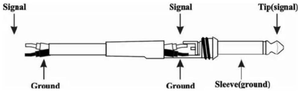
In order to ensure that your system is in phase, be careful to pay close attention to the positive and negative markings on the amplifier and wires. Make sure that the + terminal of the speaker or connector is connected to the + terminal of the power amplifier and that the - terminal of the speaker or connector is connected to the - terminal of the power amplifier.
About Impedance
Before you connect your speaker, be sure that you understand a little about impedance. Impedance is the electronic load that the speaker places on the power amplifier.
It is measured in Ohms.
IMPORTANT NOTE: There is minimum safe impedance for running power amplifiers so be sure to check the manufacturer's recommended impedance for your amplifier to avoid damaging your amplifier or voiding your warranty.
Choosing an amplifier to connect to the DJX 480 PK
The speaker has a specific power rating, which you can find out by checking the label at the back of the speaker. Refer to the Technical specifications section of this manual, to check that your power amplifier has the correct power output for this speaker. Be careful to consider the total impedance if you are connecting more than one speaker to one side of a stereo power amplifier. Using a power amplifier with a power rating that is too low can be dangerous since the output signal is often clipped in order to obtain the desired level. If the power is too high, this will result in catastrophic failure: the use of any amplifier with a power rating over the recommended power rating may damage your speakers.
Quick Set-Up
Follow the diagram and steps below to set up a basic stereo PA system quickly.
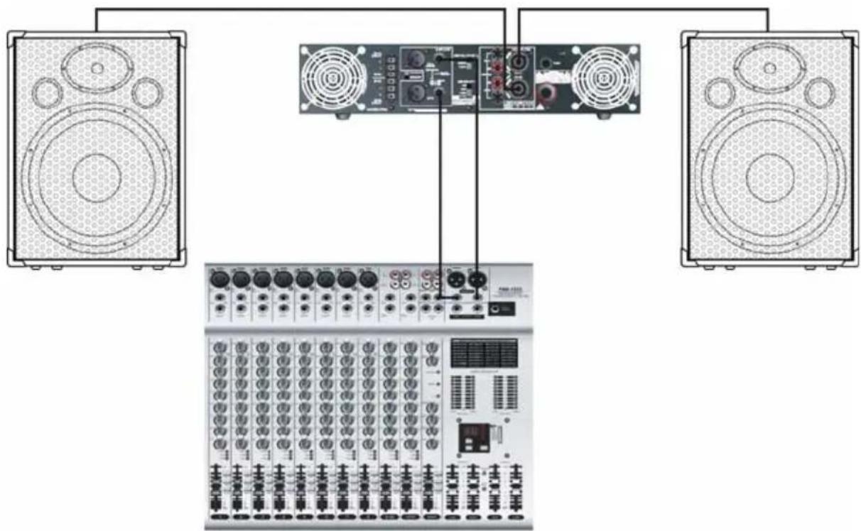
NOTE: Before plugging in and turning on the appliances, it is important to remember the rule: “LAST ON, FIRST OFF”. In other words, this means that when turning on your system, you should always turn your power amplifiers or powered monitors on LAST, and when turning your system off, turn your power amplifiers off FIRST. This helps avoid any loud noises caused by an inrush of current when the unit is switched on, as this can sometimes damage loudspeakers.
- Before making the connections, make sure that all your system components are turned off. Also, make sure that your power amplifier volume controls and the main left and right faders of your mixer are turned all the way down.
- Connect the cables to your microphones and instruments, or a CD player, to your mixer.
- Switch on the mixer, instruments and/or CD player, and then switch on your power amplifier.
- While speaking into the microphone (or playing an instrument or CD on a CD player), place the main left and right faders on the mixer to the “0” position. Ensure that the signal is not clipping. If it is, turn the mixer volume down until the signal cleans up.
- Now, slowly increase the level on your power amp until you reach the desired listening level.
Installation of the DJX 480 PK
Microphone Positioning-How to Reduce Feedback
Feedback is the annoying howling and squealing that is heard when the microphone is too close to the speaker and the volume is high. You get feedback when the microphone picks up the amplified signal from the speaker, and then amplifies through the speaker again, and then picks it up again, and so on and so on. In general, it is always recommended that any LIVE microphone (a microphone that is switched on) is positioned behind the speakers. This will allow you to obtain a better level from your system and will avoid feedback. One possible exception is when you are adjusting the sound of the microphones, since you want to be in front of the speaker to hear properly. To do this, lower the main volume while setting the EQ and effects from in front of the speakers. Once you have the sound you like, move the microphones behind the speakers and raise the main volume.
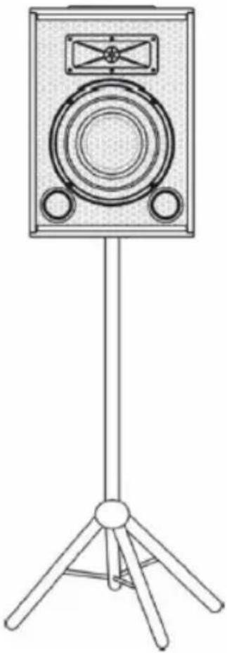
Speaker placement
Whenever possible, it is a good idea to raise the speakers above the heads of the listening audience. Some speakers have a standard 1.39" (35 mm) pole mount receptacle, which is compatible with speaker stands from a variety of manufacturers.
Technical specifications
Max. Power....300 Watts
Nominal Impedance......8 Ohms
Frequency Response......50-20k Hz
Sensitivity......95 dB
LF Driver....12-inch heavy-duty driver
HF Driver.....Piezo driver
Speaker Type......Bass Reflex
Mounting....Internal 1.39 inch (35 mm) receptacle
Net Weight....11.8 Kg

Disposal of waste electrical & electronic equipment (applicable in the European Union and other European countries with separate collection systems).
This symbol on the product or on its packaging indicates that this product must not be treated as household waste. Instead it must be handed over to the applicable collection point for the recycling of electrical and electronic equipment. By ensuring this product is disposed of correctly, you will help prevent potential negative consequences for the

environment and human health, which could otherwise be caused by inappropriate handling of this product. The recycling of materials will help to conserve natural resources. For more detailed information about recycling of this product, please contact your local authorities, your household waste disposal service or the shop where you purchased the product.
Should you have any questions/doubts on operating the unit, please send an e-mail to djtech@first-audio.com.

- SCOTT
- POWERED BY DJ-TECH
- DJX 480 PK PROFESSIONAL DJ MIXER
- CONTENTS
- FEATURES
- SAFETY PRECAUTIONS
- PARAMETERS
- NORMAL PARAMETERS
- WEIGHT AND DIMENSIONS
- APPLICATION
- DISPOSAL OF WASTE ELECTRICAL & ELECTRONIC EQUIPMENT (APPLICABLE IN THE EUROPEAN UNION AND OTHER EUROPEAN COUNTRIES WITH SEPARATE COLLECTION SYSTEMS)
- DJX 480 PK / CDX-310
- PROFESSIONAL DUAL CD PLAYER
- IMPORTANT
- PROFESSIONAL DJ DUAL CD PLAYER
- OPEN/CLOSE (OPEN/CLOSE BUTTON)
- TIME BUTTON
- LCD
- SGL (SINGLE BUTTON)
- PROG BUTTON
- PROG INDICATOR
- LOOP INDICATOR
- LOOP (LOOP BUTTON)
- PITCH INDICATOR
- JOG (JOG DIAL)
- ◀ BUTTON
- CUE (CUE BUTTON)
- 10 (TRACK +10 BUTTON)
- PLAY/PAUSE BUTTON
- PLAY INDICATOR
- BUTTON
- PITCH BEND - BUTTON
- PITCH BEND + BUTTON
- PITCH (PITCH BUTTON)
- PITCH SLIDER
- CONTROL START SOCKETS
- CONTROL CONNECTOR
- MAIN UNIT
- POWER (POWER ON/OFF SWITCH)
- OPEN/CLOSE BUTTON
- DISC COMPARTMENT
- REMOTE CONTROL CONNECTOR
- AUDIO OUT R AND L
- DIGITAL OUT SOCKET
- CONNECTIONS
- FUNCTIONS
- OPENING & CLOSING THE DISC COMPARTMENT
- LOADING DISCS
- CAUTION
- SELECTING TRACKS
- STARTING PLAYBACK
- STOPPING PLAYBACK
- PAUSING
- CUEING
- FRAME SEARCH
- SCANNING (FAST FORWARD/FAST BACKWARD)
- TIME DISPLAY
- MATCHING THE BEATS PER MINUTE (BPM) FOR TWO CDS
- PITCH BENDING +/- BUTTONS
- JOG DIAL
- PROGRAMMED PLAY
- LOOP PLAY
- RELAY PLAY
- FADER START
- INSTALLING THE UNIT
- SPECIFICATIONS
- DISPOSAL
- COMPONENTS AND FUNCTIONS
- SYSTEM CONNECTIONS
- SYSTEM CONNECTION
- OPERATION
- TROUBLESHOOTING
- TECHNICAL SPECIFICATIONS
- RATED OUTPUT FOR EACH CHANNEL
- CONSUMPTION POWER
- TABLE OF CONTENTS
- IMPORTANT SAFETY PRECAUTIONS
- COMPONENTS
- FRONT PANEL
- BACK PANEL
- CONNECTING THE SPEAKER SYSTEM
- CHOOSING THE CORRECT CABLES
- ABOUT IMPEDANCE
- CHOOSING AN AMPLIFIER TO CONNECT TO THE DJX 480 PK
- QUICK SET-UP
- INSTALLATION OF THE DJX 480 PK
- MICROPHONE POSITIONING-HOW TO REDUCE FEEDBACK
- SPEAKER PLACEMENT
Brand : SCOTT
Model : DJX 480 PK
Category : Mixer