
ENH700EXT - Access Point ENGENIUS - Free user manual and instructions
Find the device manual for free ENH700EXT ENGENIUS in PDF.


| Product Type | Outdoor Wireless Access Point |
| Brand | EnGenius |
| Model | ENH700EXT |
| Wireless Standard | IEEE 802.11b/g/n |
| Frequency Band | 2.4 GHz |
| Maximum Data Rate | 300 Mbps |
| Antenna | Built-in directional antenna (14 dBi) |
| Ports | 1 x 10/100 Ethernet (PoE) |
| Power Supply | Passive PoE (24V, 0.5A) |
| Dimensions (WxDxH) | 200 x 200 x 50 mm |
| Weight | 500 g |
| Operating Temperature | -20°C to 60°C |
| Main Functions | Access Point, Client Bridge, WDS, Repeater |
| Security | WEP, WPA/WPA2-PSK, WPA/WPA2-Enterprise, MAC Filtering |
| Management | Web-based GUI, SNMP, SSH |
| Mounting | Wall/Pole mount kit included |
| Ingress Protection | IP65 |
| Maintenance | Clean exterior with dry cloth; keep vents clear |
| Spare Parts | Contact manufacturer for replacement |
| Safety | Use only provided PoE injector; do not expose to moisture inside housing |
Frequently Asked Questions - ENH700EXT ENGENIUS
User questions about ENH700EXT ENGENIUS
0 question about this device. Answer the ones you know or ask your own.
Ask a new question about this device
Download the instructions for your Access Point in PDF format for free! Find your manual ENH700EXT - ENGENIUS and take your electronic device back in hand. On this page are published all the documents necessary for the use of your device. ENH700EXT by ENGENIUS.
USER MANUAL ENH700EXT ENGENIUS
WIRELESS OUTDOOR DUAL RADIO 802.11a/b/g/n ACCESS POINT
Model: ENH700E%>

natural_image
Exterior view of a white wireless device labeled 'EnGenius' with four vertical ports (no additional text or symbols visible)User Manual
Version 1.0
| Edition: 1.0 |
| Version: 1.1.10 |
Table of Contents
About This Document ....4
About EnGenius Technologies, Inc. 4
Product Manual Formatting ....4
Before You Start ....4
1 Product Overview....5
1.1 Contents....5
1.2 Features and Benefits....6
1.3 Environments......8
1.4 >ardware Overview 9
1.5 System Requirements for Installation 9
2 Installation and Setup....9
2.1 Installation Considerations.... 10
2.2 Assembling the EN>700EXT....10
2.3 Configuring a TCP/IP connection on Windows ^® 7/Vista....12
2.4 Configuring a TCP/IP connection on Windows® XP 16
2.5 Configuring the TCP/IP connection on Apple® Macintosh OS X....18
2.6 Logging onto the EN>700EXT 18
3 Wireless Network Modes....18
3.1 Access Point Mode 18
3.2 Client Bridge Mode....19
3.3 WDS Mode 20
4 User Interface....22
5 Status....23
5.1 Save/Reload 23
5.2 Main (System Information) 23
5.3 2.4G Wireless Client List....24
5.4 5G Wireless Client List....24
5.5 System Log 24
6 System 25
6.1 Operation Mode....25
6.2 IP Settings.... 26
6.3 Spanning Tree Settings....26
7 2.4G Wireless and 5G Wireless....27
7.1 Access Point Mode 28
7.1.1 Wireless Network 29
7.1.2 SSID Profile 30
7.1.3 Wireless MAC Filter 30
7.1.4 Wireless Advanced Settings....32
7.2 Client Bridge 33
7.2.1 Wireless Network 33
7.2.2 Wireless Advanced Settings....34
7.3 WDS....36
7.3.1 WDS Station....36
7.3.2 WDS Link Settings 36
8 Wireless Security Settings....38
8.1 WPA-PSK, WPA2-PSK, or WPA-PSK Mixed....38
8.2 WPA, WPA2, or WPA Mixed 39
8.3 WEP 40
9 Management....42
9.1 Administration 42
9.2 Management VLAN 43
9.3 Wireless Traffic Shaping 44
9.4 SNMP Settings....44
9.5 Backup / Restore Settings 45
9.6 Auto Reboot Settings....45
9.7 Firmware Upgrade....46
9.8 Time Settings....47
9.9 Log....48
9.10 Diagnostics 48
10 EnGenius Technologies Inc.: EZ ZoneController 49
10.1 ZoneController Overview 49
10.2 Features 49
10.3 Benefits....50
10.4 Compatible Devices....51
10.5 System Requirements....51
Appendix A – Troubleshooting ....52
Appendix B – Contacting Technical Support....57
Appendix C – Glossary....58
Appendix D – Statements of Conformity......63
D.1 Federal Communication Commission Interference Statement 63
D.2 Industry Canada Statement....63
D.3 Europe Declaration of Conformity....64
About This -ocument
his document is written by EnGenius >technologies, Inc. EnGenius >technologies, Inc. reserves the right to change this document without notice and all rights are reserved. >his document is written and edited for use of the configuration of the ENH700E%> by EnGenius >technologies, Inc. +lease read this document carefully before setting up the ENH700E%>. Any damage which is caused by inappropriate use will not be covered under the warranty.
About &n#enius Technologies, [nc.
EnGenius >technologies, Inc. is an industry expert in wireless communications and radio frequency (RF) technology. >he company pioneered “Affordable Long-Range Wireless” communication solutions, and creates wireless voice and data products for home, <OHO, and
Product Manual Formatting
he following symbols are using in the ENH700E%> +roduct manual to highlight key items.

Caution: >his symbol represents a vital message and is critical for the device and/or its settings.

Note: >his <ymbol represents an important message of the settings.

ip: >his symbol represents an alternative choice that can save time or resources.
Before You Start
he following equipment is required to setup the ENH700E%>:
- Computer Desktop or Laptop (Windows®, Macintosh®, or Linux-Based with Ethernet Adaptor)
• CA> 5E or CA> 6 Ethernet Cables (Q>Y: 2) -
EnGenius >echnologies, Inc. ENH700E%>
-
Ethernet crimping tool
- <crew driver set
- Refer to Chapter 2 for additional equipment that may be needed based on the network infrastructure.
1 Product Overview
hank you for purchasing the ENH700E%>. It is a powerful and enhanced Enterprise class Dual-Band Wireless-N Access +oint product with 4 multi-functions: Access +oint, Client Bridge, WD< (A+ & Bridge), and Client Router.
he EnGenius >technologies, Inc. ENH700E%> uses the latest IEEE802.11 standard, 802.11n, which allows for faster wireless throughput. >he ENH700E%> affords a great advantage to minimize the time and cost required to expand an existing business network. It operates in both 2.4 GHz and 5 GHz frequency spectrums and is also backwards compatible with legacy 802.11a/b/g networking equipment.
he ENH700E%> is easy to install in virtually any locations with its included +oE (+ower over Ethernet) injector for quick outdoor installation. In addition, the ENH700E%> enables network administrators to control its transmit power and features settings for selecting narrow bandwidth and traffic shaping. >he ENH700E%> supports wireless encryption including Wi-Fi +rotected Access (W+A-+<K/W+A2-+<K), [64/128/152]-bit WE+ Encryption, and IEEE 802.1x with RADIU<. Additionally, the ENH700E%> can be paired with other EnGenius >technologies, Inc. Outdoor Wireless Access +oint and Bridge products in Access +oint – Client Bridge or WD< Bridge – WD< Bridge deployments.

Damage may occur if installing with another PoE adaptor that is not provided with the EN>700EXT.
1.1 Contents
Open the ENH700E%> Wireless Access +oint / Client Bridge package to ensure that all the following contents are present:
- EnGenius >technologies, Inc. ENH700E%> Wireless Access +oint / Client Bridge
• 48V/380mA +ower Adaptor
• +oE (+ower Over Ethernet) Injector (E+E-48GR)
• 2.4 GHz 5dBi Onmi Antenna (x 2) and 5 GHz 5dBi Onmi Antenna (x 2) -
Mounting Kit with Bracket-Mount <pecial <crew <et
-
Mounting Installation Guide
• ENH700E%> Quick Installation Guide - ENH700E%> +roduct CD - includes EZ Controller Access +oint Management
User Manual in Adobe Acrobat +DF)
Do not discard the packing materials in case of a return. >he unit must be shipped in its original packaging for a valid return. If any of the contents are missing, please contact your reseller.

Using a power adaptor other than the one included with the EN>700EXT may cause damage to the device and void the product warranty.
1.2 Features and Benefits
| Dual Mode <imultaneously transmits wireless signals in both the 2.4GHz and5GHz frequency spectrums. >his expands the number of wirelessclient devices that can access the network. | |
| Separate Mode Each one of the two radio having its own operation mode. >hisincrease more options to have a flexible wireless network design. | |
| Access Point Mode >he most typically used operation mode for the ENH700E%>. InAccess +oint mode, the ENH700E%> will allow wireless devicesaccess to transmit and receive data from ENH700E%> | |
| Client Bridge Mode In this mode, the ENH700E%> can connect to another Access+oint to extend the range of the wireless network. | |
| Client Router Mode In this mode, the ENH700E%> can be used as a Client Bridge butwith support for a WAN type of Internet connection. >his israrely used in commercial environment. | |
| WDS AP With this mode selected, the device can pair with other deviceswith either WD< A+ mode or WD< <>A mode. When connectedwith other ENH700E%> with WD< A+, the device acts as A+ plusWD< bridge, therefore repeater function is available while withsignificant performance cut; When paring WD< A+ to WD< <>A toother devices (point-to-multipoints), transparent bridging issupported. | |
| WDS Station mode | WD<ree Function. |
| WDS Bridge mode In the WD< Bridge Mode, the ENH500 can wirelessly connectdifferent local area networks by configuring each device's MACaddress and security settings. WD< Bridge mode providetransparent bridging function. unlike Access +oint Mode. A+slinked by WD< are using the same wireless channel, andconnecting excessive numbers of A+s on the same channel mayresult in lower throughput. +lease be aware to avoid loopconnections; otherwise enable theree Function. | |
| Multiple SSIDs >he ENH700E%> supports up to 16 < | |
| in Access +oint mode (8 <He following options can be set to each < | |
| • < | |
| • Each < | |
| • Authentication is fully supported | |
| • VLAN Identifier | |
| WMM >his feature provide Qo< (Quality of service) for prioritizing multimedia traffic. | |
| Wi-Fi Protected Access Wi-Fi +protected Access is a standards-based interoperable security enhancement that increases the level of data protection and access control for existing and future Wireless LAN systems. It is compatible with the IEEE802.11i standard W+A that leverages >KI+ and 802.1x for authenticated key management. | |
| >igh Speed Data Rate (Up to 300 Mbps) | As specified in the IEEE802.11n standard; capable of handling heavy data payloads such as HD Video |
| >igh Output Power (Up to 27 dBm) | Designed to extend range and maximize signal coverage area. |
| IEEE 802.11 a9b9g9n Compliant | Fully interoperable with IEEE 802.11 a/b/g/n compliant devices. |
| MAC Address filtering in Access Point mode | Allows network administrators to grant network access only to computers and other devices based on their known MAC (Media Access Control) addresses |
| Support RSSI Indicator in Client Bridge mode | Enables device installer to select the best signal when aiming to Access +oints therefore to have proper installation |
| Power-Over-Ethernet Enables installers to connect the ENH700E%> to a switch via Ethernet in locations where a power outlet may be unavailable. (NO>E: >he ENH700E%> includes the proprietary +oE Adaptor, E+E-48GR). | |
| IP 68 >he ENH700E%>'< housing is rated with I+68, which is highest I+ rating with total water and dust proof. so it to be placed on a building's exterior for maximum range and coverage and allows it to operate in the extremely harsh environmental conditions. | |
7.3 A Cost-Effective Wireless Solution to Extend and Expand an Existing Network
he following list describes the solutions that the ENH700E%> offers as a flexible, robust and powerful Outdoor Access +oint or Bridge:
- Difficult-to-Wire Environments - In outdoor environments sometimes extending a network by laying Ethernet or fiber cabling is either cost prohibitive or physically not possible. >he ENH700E%>, enables the extension of an existing company network via the propagation of a wireless signal rather than cable as a much more cost-effective alternative.
- Temporary Workgroups – Creating a wired network infrastructure for a temporary outdoor worksite/workgroup or special event venue may not be a cost- or time-efficient solution and may present deployment issues if trenches for cabling cannot be dug in existing landscaping. >he ENH700E%> enables companies, in a matter of minutes, to create an outdoor wireless network that can provide Internet access (based on an existing broadband connection) or access to the company’s networked resources like printers, hard drives and databases.
- Wireless Extensions of Ethernet Networks – >he range of a wired network is typically limited within the confines of a single building. In situations where there are multiple buildings on a campus or another company building very remote from the main building then a Wireless Access +oint or Bridge deployment using the ENH700E%> provides a very cost-effective way to cover large outdoor areas around a company office or even connect to other company buildings.
- Expanding User Capacity and Connectivity To Additional Devices – >he ENH700E%> is designed specifically to extend and expand existing company networks. Its high transmit power capability and enhanced receive sensitivity results in the ability for a company to connect to more employees, company guests or other wireless clients. >he ENH700E%>’s additional 5GHz frequency radio can be act as a separate A+ or bridge to either provide 5GHz wireless access to 5GHz clients; Or connect to other 5GHz devices to provide backhaul service.
- Redundancy – In situations where a portion of an existing wired network may fail, the ENH700E%> offers a measure of stability and redundancy to other employees can continue to communicate with one another or access mission critical databases.
7.4 >ardware Overview
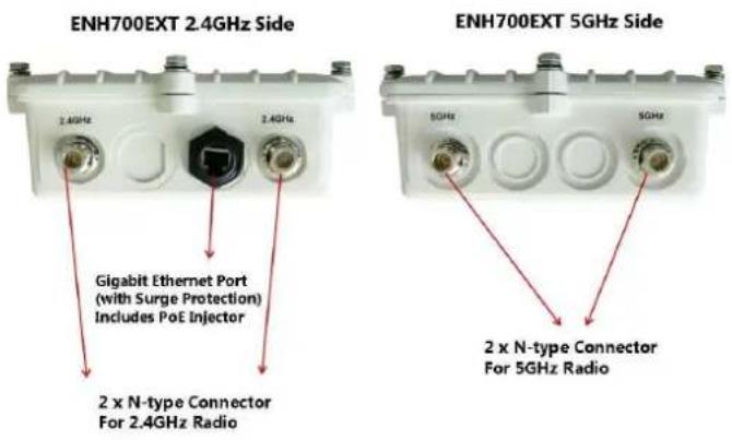
| Physical Interface | 10/100/1000 LAN Port with (48v Proprietary) PoE <upport |
| Maximum Wireless Data Rate | 300Mbps + 300Mbps |
| Antennas 2.4 GHz – 5dBi Omni directional antenna x2 | 5 GHz – 5dBi Omni directional antenna x2 |
Physical Appearance
7.5 System Requirements for Installation
he minimum requirements for settings up the ENH700EX> are:
- A computer with an Ethernet interface and a Windows (XP, Vista, 7), Mac O<X, or Linux based Operating <system.
- An Internet browser the supports H>>P and Java<cript.

2 Installation and Setup
his chapter will describe how to assemble and set up the ENH700EX>. It will also cover where to place the ENH700EX> to allow for maximum range and signal.
2.1 Installation Considerations
here are many considerations on where to place the ENH700E%>. >he followings are the main considerations on where to mount the device. >he first consideration is available line of sight to the area or building that you wish to provide wireless network connectivity. Other buildings, mountains, hills, trees, thick brush can all attenuate the or inhibit the wireless signal.
he second consideration is distance. You should calculate the EIR+ (Effective Isotropic Radiated +ower) correctly to properly configure the ENH700E%> using this calculation for the distance you intend to build the wireless link (see Glossary at the end of this manual for the EIR+ formula). Don't place multiple ENH700E%>’s too far away from one another since the A+ uses default Omni directional (not directional) antennas. If you plan to have a longer range connection, you can consider identically-matching directional antennas to connect to the ENH700E%> on both transmit and receiving ends.
2.2 Assembling the EN>700EXT
Carefully remove the ENH700E%> unit, the Omni 5dBi and 2.4dBi Antennas(two each), E+E-48GR +oE Injector, and power adaptor. As mentioned earlier in this Manual, the Ethernet cables are required and not provided within the ENH700E%> package.
- Install all 4 antennas onto the ENH700E%> by screwing them toward the ENH700E%> until the threads on the screw are not visible.
2.

Ensure that all antennas screw on straight. Failure to do so may damage the ENH700E%> antenna connectors
-
Insert a shielded Ethernet cable into the RJ-45 port on the ENH700E%>. You need to consider the length of this cable based on the distance from where the +oE injector is which in a weather protected place such as indoor or a water tight box to the ENH700E%>. Use high quality cable is highly recommended.
-
Insert the other end of the Ethernet cable to the E+E-48GR +oE Injector on the port labeled AP9Bridge.
-
ake a second Ethernet cable and connect it to the Network port of the E+E-48GR +oE Injector.
-
Insert the other end of the second Ethernet cable into the Ethernet controller of the computer system in which the ENH700E%> will be set up.
- +lug the power cord of the power adapter into the E+E-48GR port labeled -C [N.
- +lug the power adaptor into the power outlet.
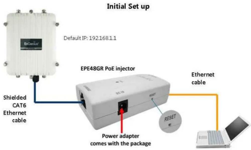

he ENH700E%> provides a proprietary +oE adapter. +lease only use the supplied +oE adapter and its power adapter.
4
2.3 Configuring a TCP9IP connection on Windows® 79Vista
Use4the4following4procedure4to4configure4a4computer4running4MicroWorlds 7.44
- 4In4the4< tart4menu4search4box,4type:4ncpa.cpl 4

- When4the4Network4Connections4List4appears,4right-click4the4Local Area Connection4icon4and4click4Properties.4

- In the Networking tab, click Internet Protocol Version 4 (TCP9IPv4), and then click Properties.

- In the properties dialog box, click Use the following IP address: to configure your computer for
C+/I+. Enter an IP address (i.e. 192.168.1.10), the subnet mask of the ENH700E%>, and the default gateway which is the ENH700E%>’s I+ address, 192.168.1.1. Note: the subnet mask must match that of the ENH700E%> and the I+ address must be on that subnet. - Click the OK button to save your changes and close the dialog box.
- Click the OK button again to save your changes.
Configuring Microsoft® Windows Vista
Use the following procedure to configure a computer running Microsoft ^® Windows Vista with the default Windows interface.
- On the Windows taskbar, click Start, click Control Panel, and then select the Network and Internet icon.
- Click View Network Status and tasks and then click Manage Networks Connections.
- Right-click the Local Area Connection icon and click Properties.
-
Click Continue. >he Local Area Connection + properties dialog box appears.
-
In the Local Area Connection +properties dialog box, verify that Internet Protocol (TCP9IPv4) is checked. >hen select Internet Protocol (TCP9IPv4) and click the Properties button. >he Internet +protocol Version 4 +properties dialog box appears.

- In the properties dialog box, click Use the following IP address: to configure your computer for
C+/I+. Enter an IP address (i.e. 192.168.1.10), the subnet mask of the ENH700E%>, and the default gateway which is the ENH700E%>’s I+ address, 192.168.1.1. Note: the subnet mask must match that of the ENH700E%> and the I+ address must be on that subnet.

- Click the'? button to save your changes and close the dialog box.
- Click the'? button again to save your changes.
2.4 Configuring a TCP9IP connection on Windows® XP
Use the following procedure to configure a computer running Microsoft ^® Windows XP with the default Windows interface.
- On the Windows taskbar, click Start, click Control Panel, and then click Network and Internet Connections.
- Click the Network Connections icon.
- Click Local Area Connection for the Ethernet adapter connected to the ENH700E%>. >he Local Area Connection <tatus dialog box appears.
- In the Local Area Connection
he Local Area Connection +properties dialog box appears.
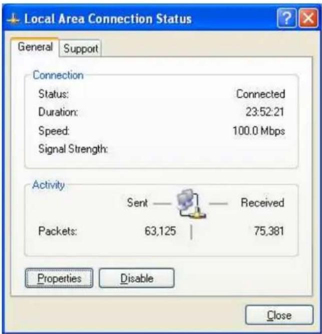
- In the Local Area Connection + properties dialog box, verify that Internet Protocol (TCP9IP) is checked. >hen select Internet Protocol (TCP9IP) and click the Properties button. >he Internet +rotocol (>C+/I+) + properties dialog box appears.
- In the properties dialog box, click Use the following IP address: to configure your computer for
C+/I+. Enter an IP address (i.e. 192.168.1.10), the subnet mask of the ENH700E%>, and the default gateway which is the ENH700E%>’s I+ address, 192.168.1.1. Note: the subnet mask must match that of the ENH700E%> and the I+ address must be on that subnet. -
Click the OK button to save your changes and close the dialog box.
-
Click the OK button again to save your changes.
2.4.1 Configuring Apple® Mac OS X
he following procedure describes how to configure >C+/I+ on an Apple ^® Macintosh running Mac OS X 10.2 or later. Note: >he menu titles and placement vary in each O<% (10.x) operating system but are similar.
- +ull down the Apple Menu, click System Preferences, and select Network.
- Verify that the NIC connected to the ENH700E%> is selected in the Show field.
- In the Configure field on the TCP9IP tab, select Manually.
- Click Apply Now to apply your settings and close the >C+/I+ dialog box.
- Enter an IP address (i.e. 192.168.1.10), the subnet mask of the ENH700E%>, and the Router which is the ENH700E%>’s I+ address, 192.168.1.1. Note: the subnet mask must match that of the ENH700E%> and the I+ address must be on that subnet.
- Click Apply Now to apply your settings and close the >C+/I+ dialog box.


In <tep 2, if the Configure IPv4 menu list isn't available, select Advanced. In the TCP9IP tab, you will be able to enter the information in <tep 4.
2.5 Logging onto the EN>700EXT
After completing the >C+/I+ settings from the beginning of the Chapter, you can now access the web-based configuration menu.
- Open your web browser.
- Enter I+ 192.168.1.1 into your address bar.
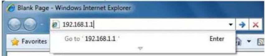

he default username of the ENH700E%> is admin. >he default password of the ENH700E%> is admin. If you have changed the ENH700E%> LAN I+ address, make sure to enter the correct I+ Address.
3 Wireless Network Modes
his chapter will explain the different operation modes that the ENH700E%> has to offer. >his will help in determining how you would like to set up the ENH700E%> for the proper mode for your specific networking needs in the later chapters of the User Manual.
he three native operation modes of the ENH700E%> are Access +oint, Client Bridge, and WD< (WD<A+, WD< <>A, WD< Bridge). Both Radio 1 and Radio 2 support these modes.
3.1 Access Point Mode (AP mode)
Access +oint Mode is the most typically used mode for the ENH700E%>. In Access +oint mode, the ENH700E%> extends an existing network by providing signal coverage outside of a building creating a Wireless LAN enabling employees or company guest to access the company network and the company's broadband Internet connection as designated and authorized by the network administrator. <tations and clients must utilize the same <<ID and <security +assword to associate while within range of the wireless signal.

flowchart
Network architecture diagram showing client-AP and 5GHz network connections between ENH200/ENH202 and ENH500 devices with router, switches, and mobile devices.
3.2 Client Bridge Mode
In the Client Bridge mode, the ENH700E%> functions like a wireless network adaptor. >his allows the ENH700E%> to share the acquired wireless network access (via another device in Access +oint mode) with wired devices connected via Ethernet to it (typically via a networked switch).

flowchart
graph LR
    A["main office"] --> B["server"]
    A --> C["PC"]
    A --> D["work station"]
    B --> E["AP mode"]
    C --> E
    D --> E
    E --> F["CB mode"]
    F --> G["server"]
    F --> H["PC"]
    F --> I["PC"]
    E --> J["interference"]
    F --> K["interference"]
    style A fill:#f9f,stroke:#333
    style B fill:#ccf,stroke:#333
    style C fill:#ccf,stroke:#333
    style D fill:#ccf,stroke:#333
    style E fill:#cfc,stroke:#333
    style F fill:#cfc,stroke:#333
    style G fill:#fcc,stroke:#333
    style H fill:#fcc,stroke:#333
    style I fill:#fcc,stroke:#333
    style J fill:#cff,stroke:#333
    style K fill:#cff,stroke:#333
3.3 WDS Mode
In WD< (Wireless Distribution
1) WD< with Access +oint – Expands the WD< through the use of Access +oints. Clients can connect to the device as a normal Access +oint.
2) WD< <tation – Expands the WD< by receiving a wireless signal/service and sharing through the Ethernet port.
Extremely Robust Coverage

flowchart
graph TD
    A["ENH202 11n 2.4GHz Client Bridge"] --> B["WDS STA mode"]
    B --> C["ENH500 11n 5GHz Client Bridge"]
    C --> D["ENH700EXT"]
    D --> E["WDS AP mode"]
    E --> F["ENH500 11n 5GHz Client Bridge"]
    F --> G["WDS STA mode"]
    style A fill:#f9f,stroke:#333
    style B fill:#ccf,stroke:#333
    style C fill:#cfc,stroke:#333
    style D fill:#fcc,stroke:#333
    style E fill:#cff,stroke:#333
    style F fill:#ffc,stroke:#333
    style G fill:#fcc,stroke:#333
ENH700E%> with WD<A+ and WD<<>A (<tation) modes example
3) WD< with Bridge – Expands the Wireless Distribution <system through the use of wireless bridges. Clients won't connect to the device as a bridge
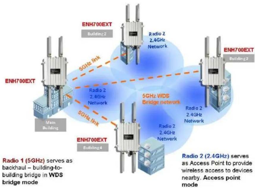
flowchart
graph TD
    A["ENH700EXT"] -->|5GHz link| B["Radio 2 2.4GHz Network"]
    A -->|5GHz link| C["ENH700EXT Building 2"]
    A -->|5GHz link| D["ENH700EXT Building 3"]
    A -->|5GHz link| E["ENH700EXT Building 4"]
    F["Radio 1 (5GHz) serves as backhaul – building-to-building bridge in WDS bridge mode"] --> G["Radio 2 (2.4GHz) serves as Access Point to provide wireless access to devices nearby. Access point mode"]
    H["ENH700EXT Building 2"] --> I["Radio 2 2.4GHz Network"]
    H --> J["ENH700EXT Building 3"]
    H --> K["ENH700EXT Building 4"]
ENH700E%> with WD<A+ and WD< Bridge mode as backhaul example
W-S :ridge Mode
In the WD< Bridge mode, the ENH700E%> can wirelessly connect different LANs (Local Area Networks) by applying a device's MAC address to its associated security settings as prescribed by the network administrator. WD< Bridge mode can bridge up to four local wired networks together as one logical network. Every computer on this logical network can see each other, sharing files as if they are in the same location. With high output power and MIMO antenna technology, the connection distance can extend beyond 1000 feet with great performance, assuming the antennae are within line of sight. >he WD< bridge network is a MAC-based network that provides transparent bridging
4 User Interface
Once logged into the ENH700E%>, the home screen will appear.

-
he operation mode of the ENH700E%> will be displayed. >he current 2.4GHz operation mode will be displayed first followed by the current 5GHz operation mode.
-
he main menu of the ENH700E%> will contain all the configuration options and settings.
-
he current configuration menu will be displayed in this section of the user interface.
ome button will bring the user interface back to the main status page. -
he Reset button will prompt you with a couple of system commands:
a. Reboot the Device – >his selection will allow restart the ENH700E%>.
b. Restore to Factory Defaults – >his selection will restore all the default settings of the ENH700E%> to the base factory settings.
5 Status
5.7 Save9Reload
When making any changes to ENH700E%>, it will be placed in the Save 9 Reload option of the Status section.
Save/Reload
Home
Reset
Unsaved changes list
network.sys.opmode=ap'
wireless.wifi0.countryName=N/A
Caution: Network Setting changed, redirect IP to 192.168.1.1
Save & Apply
Revert
NOTE
No changes made in the proceeding chapters of this manual will take effect until Save & Apply is selected. <electing Revert will erase any changes made.
5.2 Main (System Information)
he Main option of the Status section of the user interface menu contains the information and status of the ENH700E%>. >he device current status information includes four section:
1) System Information – >his sections displays general information of the ENH700E%> such as the device name, firmware version, and the MAC addresses associated with different Wireless Bands and <
3) Current 2.4G Wireless Settings – >his sections displays the current operation mode of the 2.4 GHz wireless radio and the various settings associated with it.
4) Current 5G Wireless Settings – >his sections displays the current mode of the 5 GHz wireless radio and the various settings associated with it.
5.3 2.4G>z Wireless Client List
he 2.4G>z Wireless Client List option of the Status section of the user interface menu displays all the clients connected to the 2.4G>z operation of the ENH700E%>.
5.4 5G>z Wireless Client List
he 5G>z Wireless Client List option of the Status section of the user interface menu displays all the clients connected to the 2.4G>z operation of the ENH700E%>.
5.5 System Log
he System Log option of the Status section displays all actions and events taking place in the ENH700E%>. Older entries are deleted for newer entries. >his option is used to help users debug the ENH700E%>.
| System Log | Home | Reset | |||
| Show log type | All | ||||
| Oct 19 10:16:58 (none) user.warn kernel: jffs2_build_filesystem(): erasing | |||||
| Oct 19 10:16:58 (none) user.info kernel: mini_fo: using storage directory: | |||||
| Oct 19 10:16:58 (none) user.info kernel: mini_fo: using base directory: / | |||||
| Oct 19 10:16:34 (none) user.warn kernel: jffs2_scan_eraseblock(): End of f | |||||
| Oct 19 10:16:34 (none) user.warn kernel: jffs2_build_filesystem(): unlocki | |||||
| Oct 19 10:16:33 (none) user.warn kernel: ar5416SetSwitchCom, ant switch co | |||||
| Oct 19 10:16:33 (none) daemon.info dnsmasq[823]: using local addresses onl | |||||
| Oct 19 10:16:33 (none) daemon.info dnsmasq[823]: using local addresses onl | |||||
| Oct 19 10:16:33 (none) daemon.info dnsmasq[823]: started, version 2.52 cac | |||||
| Oct 19 10:16:33 (none) daemon.info dnsmasq[823]: reading /tmp/resolv.conf. | |||||
| Oct 19 10:16:33 (none) daemon.info dnsmasq[823]: read /etc/hosts - 1 addre | |||||
| Oct 19 10:16:33 (none) daemon.info dnsmasq[823]: compile time options: IPv | |||||
| Oct 19 10:16:31 (none) user.info kernel: device ath0 entered promiscuous m | |||||
| Oct 19 10:16:31 (none) user.info kernel: br-lan: topology change detected, | |||||
| Oct 19 10:16:31 (none) user.info kernel: br-lan: port 3(ath0) entering lea | |||||
| Oct 19 10:16:31 (none) user.info kernel: br-lan: port 3(ath0) entering for | |||||
| Oct 19 10:16:30 (none) user.warn kernel: osif_vap_init : wait for connecti | |||||
| Oct 19 10:16:30 (none) user.info kernel: device ath0 left promiscuous mode | |||||
| Oct 19 10:16:30 (none) user.info kernel: br-lan: port 3(ath0) entering dis | |||||
| Oct 19 10:16:25 (none) user.warn kernel: start running | |||||
| Oct 19 10:16:25 (none) user.warn kernel: set SIOC80211NWID, 8 characters | |||||
| Oct 19 10:16:25 (none) user.warn kernel: osif_vap_init : wakeup from wait | |||||
6 System
he System section of the user interface menu allows the user to change of the operation modes of both the 2.4GHz and 5GHz radios as well as set up the
ree settings between multiple ENH700E%> units.

No changes made in the System section of the ENH700E%> will be in effect until Save & Apply is selected in the Save9Reload option of the Status section. <electing Accept or Save in the System section will not reconfigure the router.
6.7 Operation Mode
In Operation Mode, the user will select how each wireless band will operate.

Device Name >he name associated with the ENH700E%> on the wireless network or to other network devices.
Country 9 Region
Operation Mode <elect the operation mode for both the 2.4GHz wireless band and the 5GHz wireless band. When WD< mode is selected, the type of WD< must be specified by selecting Access +oint, Bridge, or WD< <tation.
6.2 IP Settings
he IP Settings option of the System section allows the user to configure the I+ settings.
IP Settings
Home
Reset
System Information
| IP Network Setting | Obtain an IP address automatically (DHCP)Specify an IP address | |||
| IP Address | 192 | 168 | 10 | 7 |
| IP Subnet Mask | 255 | 255 | 255 | 0 |
| Default Gateway | 192 | 168 | 10 | 1 |
| Primary DNS | 192 | 168 | 10 | 1 |
| Secondary DNS | 4 | 2 | 2 | 2 |
Accept Cancel
1) I+ Network
2) I+ Address -
3) I+ <ubnet Mask - <pecify the
4) Default Gateway -
5) +primary DN< - <pecify the +primary DN< of the ENH700E%>.

When changing the I+ Address or Default Gateway, the I+ Address used to access the ENH700E%> when logging in will change.
6.3 Spanning Tree Settings
he Spanning Tree Settings option of the System section allows the user to configure the spanning tree settings of the ENH700E%>.

<etting up a
| Spanning Tree Settings | ||
| Home Reset | ||
| Spanning Tree Status | On Off | |
| Bridge Hello Time | 2 seconds (1-10) | |
| Bridge Max Age | 20 seconds (6-40) | |
| Bridge Forward Delay | 4 seconds (4-30) | |
| Priority | 32768 (0-65535) | |
Accept Cancel
| Spanning Tree Status Enable the use of | |
| Bridge >ello Time | >he amount of time before the connections times out. |
| Bridge Max Age >he maximum amount of time the connection between nodes will last. | |
| Bridge Forward Delay | >he amount of time to elapse before data is forwarded. |
| Priority >he priority of the device in the spanning tree. | |
7 2.4G>z Wireless and 5G>z Wireless
In both the 2.4G>z Wireless and 5G>z Wireless sections, the user will be able to configure operation mode settings the 2.4GHz or the 5GHz radio respectively. >he settings that will be available to change is dependent on the selections chosen in Operation Mode (Chapter 6.1 - +age 13) option in the System section of the user interface menu. For more information about the modes of operation, refer to Chapter 3 (+age 10).

ENH700E%> can only operate a Client Bridge (WD< or not) or WD< <tation on a single band. It cannot operate bridges or stations concurrently on both 2.4GHz or 5GHz.

he changes made in the 2.4G>z Wireless or 5G>z Wireless sections of the ENH700E%> won't be in effect until Save & Apply is selected in the Save9Reload option of the Status section.
z Wireless or 5G>z Wireless sections will not reconfigure the device.
7.1 Access Point Mode
When Access +oint is the selected mode of operation for either the 2.4GHz or 5GHz bands, three options will be available to configure. >he three options that can be configured are Wireless Network, Wireless MAC Filter, and Wireless Advanced Settings.
Access Point configuration
| Login to the web-based configuration interface with default I+ 192.168.1.1 | |
| elect your country or region's regulation. | |
| Use site survey to scan channels of the nearby area. | |
| elect a channel with less interference. | |
| <pecify the <<ID for your broadcast <<ID and you can also configure multiple <<ID at the same time. | |
| Verify VLAN identifier in order to separate services among clients | |
| <etup the authentication settings. | |
| <elect Apply to process all of the configurations. |

flowchart
graph LR
    A["main office"] --> B["server"]
    A --> C["PC"]
    A --> D["work station"]
    B --> E["AP mode"]
    C --> E
    D --> E
    E --> F["CB mode"]
    F --> G["server"]
    F --> H["PC"]
    F --> I["PC"]
    E --> J["interference"]
    F --> K["interference"]
    G --> L["IP 192.168.1.5 encrypt: WPA AES"]
    H --> M["IP 192.168.1.100 encrypt: WPA AES"]
    I --> N["PC"]
EN>700EXT Access Point to Client Bridge mode setting diagram
7.1.1 Wireless Network
| Wireless Mode | 802.11 B/G/N Mixed | |||
| Channel HT Mode | 40MHz | |||
| Extension Channel | Upper Channel | |||
| Channel / Frequency | Ch1-2.412GHz | Auto | ||
| AP Detection | Scan | |||
| Current Profiles | ||||
| SSID | Security | VID | Enable | Edit |
| EnGenius1-2.4G | None | 1 | √ | Edit |
| EnGenius2-2.4G | None | 2 | ☐ | Edit |
| EnGenius3-2.4G | None | 3 | ☐ | Edit |
| EnGenius4-2.4G | None | 4 | ☐ | Edit |
| None | ☐ | Edit | ||
| None | ☐ | Edit | ||
| None | ☐ | Edit | ||
| AP SSID | None | 1 | √ | Edit |
| Wireless Mode | |
| will use. >he options are:1) 802.11 b/g/n Mixed2) 802.11 b3) 802.11 b/g Mixed4) 802.11 g5) 802.11 n only | |
| Channel >T Mode | |
| he larger the channel used, the throughput will be much better. Using a lower channel, will increase the distance and stability of the signal. | |
| Extension Channel | If the Channel H> Mode was set to 40Hz, the ChannelFrequency can be set ifAutois not selected. >he Upper Channel is associated with frequency channels 1-7, while the Lower Channel is associated with channels 5-11. |
| Channel 9 Frequency | |
| will operate in for the corresponding band. >his option is only available ifAutois not selected. | |
| AP Detection >o help select a specific channel / frequency to use, the ENH700E%> can scan all the wireless access points in the area to help select the optimal settings. | |
| Current Profiles >he ENH700E%> can operate up to total 16 < | |
concurrently in Access +oint mode (8 <<IDs per Radio). Each <<ID will have associated settings that can be edited by pressing the Edit button. For an <<ID to be active and discoverable, the checkbox associated to the <<ID must be marked.
7.1.2 SSID Profile
Wireless Setting
| SSID | EnGenius1-2.4G (1 to 32 characters) |
| Suppressed SSID | |
| Station Separation | Enable Disable |
| Wireless Security | |
| Security Mode | Disabled |
| SSID | >he < |
| Suppressed SSID | By checking the Suppressed SSID so clients scan for access point will not see the < |
| Station Separation When enabled, clients will not be able to communicate with other devices connected via Access +oint within the ENH700E%. | |
| Security Mode <et the security options for the Access +oint. For more information on Wireless security, refer to Chapter 8 (+age 23). | |
7.1.3 Wireless MAC Filter

ACL Mode <elect whether the MAC Addresses listed will be the only clients granted access or denied service in the Access +oint.
Add Enter the MAC Address of the device to be added to the filtering list. Once entered, press Add.
# >he number on the list associated with the client MAC address.
7.1.4 Wireless Advanced Settings
/ Wireless Advanced Settings
Home
Reset

| Data Rate >he Data Rate of the ENH700E%> affects the throughput of data transfer. A higher data rate selected will have a faster throughput. Lower will increase the distance in which the signal will reach. |
| Transmit Power >he transmit power will allow the ENH700E%> to extend the area of coverage. However, when increasing it too much, the wireless connection may be unstable. |
| RTS 9 CTS Threshold (1-2346) >he number on the list associated with the client MAC address. >his option affects the size of the packets that will be passed along to transmit data. |
| Distance (1-30km) <specify the distance between the access points and clients.Further distances will result in lower connection speeds. |
| Aggregation Aggregation allows packets to be sent together to lower the amount of transmissions. |
7.2 Client Bridge
When Client Bridge is the selected mode of operation for either the 2.4GHz or 5GHz bands, two options will be available to configure. >he two options that can be configured are Wireless Network and Wireless Advanced Settings.
7.2.1 Wireless Network
2.4G / Wireless Network

| Wireless Mode | 802.11 B/G/N Mixed |
| SSID | Specify the static SSID : ( 1 to 32 characters ) Or press the button to search for any available WLAN Service. Site Survey |
| Preferred BSSID | ☐ : ☐ : ☐ : ☐ : ☐ : ☐ |

Accept Cancel
Wireless Mode
1) 802.11 b/g/n Mixed
2) 802.11 b
3) 802.11 b/g Mixed
4) 802.11 g
5) 802.11 n only
SSID In Specify the static SSID, enter the name of the Access +oint the client will connect to. >his area is automatically filled out if an access point in Site Survey is selected.
Preferred BSSID
Security Mode <et the security options for the client bridge. For more information on Wireless <security, refer to Chapter 8 (+age 23).
7.2.2 Wireless Advanced Settings

Accept Cancel
| Data Rate >he Data Rate of the ENH700E%> affects the throughput of data transfer. A higher data rate selected will have a faster throughput. Lower will increase the distance in which the signal will reach. |
| Transmit Power >he transmit power will allow the ENH700E%> to extend the area of coverage. However, when increasing it too much, the wireless connection may be unstable. |
| RTS 9 CTS Threshold (1-2346) >he number on the list associated with the client MAC address. >his option affects the size of the packets that will be passed along to transmit data. |
| Distance (1-30km) <pecify the distance between the access points and clients.Further distances will result in lower connection speeds.+lease note, the distance setting allows you to control to ACK timing, it is not a tool for you to measure distance. |
| Aggregation Aggregation allows packets to be sent together to lower the amount of transmissions. |


No changes made in the System section of the ENH700E%> will be in effect until Save & Apply is selected in the Save9Reload option of the Status section. <electing Accept or Save in the System section will not reconfigure the router. Changing Wireless Advanced <ettings may lower the wireless connection quality. +lease keep all settings as default unless you understand the modifications which you have made
Client Bridge Configuration
<step 1 Login to the web-based configuration interface with the default I+: 192.168.1.1
<tep 2 <elect your country or region's regulation.
<tep 3 <elect Operation Mode to Client Bridge from System Properties.
<tep 4 Use site survey to scan channels of the nearby area.
<tep 5 <elect the A+ that you would like to associate with.
<tep 6 <etup the authentication settings that match to the Access +oint's settings.
<tep 7 <elect Apply to process all of the configurations.
he Client-Bridge's I+ settings must match the Access +oint's settings to be on the same subnet.

flowchart
graph LR
    A["main office"] --> B["server"]
    A --> C["PC"]
    A --> D["work station"]
    B --> E["EriGenius"]
    C --> E
    D --> E
    E --> F["AP mode"]
    E --> G["CB mode"]
    F --> H["sample config: IP 192.168.1.5 encrypt: WPA AES"]
    G --> I["sample config: IP 192.168.1.100 encrypt: WPA AES"]
    H --> J["server"]
    H --> K["PC"]
    H --> L["PC"]
    I --> M["server"]
    I --> N["PC"]
    J --> O["secondary office"]
    K --> O
    L --> O
EN>700EXT Access point to Client Bridge mode setting diagram
7.3 WDS Mode
When a WDS mode is selected, WDS Access Point is set up the same as Access Point mode and WDS Bridge is set up the same as Client Bridge mode. >he only difference is WDS Link Settings. >he WDS Link Settings is used to setup a connection between access points without limiting or removing functionality. Wireless Distributed <systems are used to greatly increase coverage and allow different LANs to communicate with each other.
7.3.1 WDS Station
Another mode of operation of the ENH700E%> is WDS Station. In WDS Station, the ENH700E%> will be used as the central location of the WDS. >o setup the Wireless Network and Wireless Advanced Settings for the WDS, refer to Chapter 7.2 (+age 19).
7.3.2 WDS Link Settings

Security <et the security options for the WD< Link <ettings. For more information on Wireless security, refer to Chapter 8 (+age 23).
| WEP Key | Enter the WE+ Key to be used. |
| AES Passphrase Enter the AE< +assphrase (password) to be used. | |
| MAC Address <pecify the distance between the access points and clients.Further distances will result in lower connection speeds. | |
WDS Bridge Configuration
<tep 2 <elect your country or region's regulation.
<tep 3 Change Operation Mode to WDS Bridge under System Properties.
<tep 4
<tep 5 <et the WLAN settings under Wireless Network.
<step 6 Configure WD< Link <settings under Wireless.
<step 7 <pecify the MAC address of the bridge(s) which you would like to connect with.
<step 8 +ress Apply under Save / Reload to process all of the configurations.
* Each WD<bridge device must use the same <ubnet, Wireless Mode, Wireless Channel, and <security <etting.
* With the MAC secured based WD< bridge network, only WE+ encryption is available

flowchart
graph TD
    A["ENH700EXT"] -->|5GHz link| B["ENH700EXT Building 2"]
    A -->|5GHz link| C["ENH700EXT Building 4"]
    D["ENH700EXT"] -->|5GHz WDS Bridge network| E["ENH700EXT Building 3"]
    F["Radio 1 (5GHz) serves as backhaul – building-to-building bridge in WDS bridge mode"] --> A
    F --> D
ENH700EXT multiple buildings bridged network (WDS)
8 Wireless Security Settings
Wirelessly securing the Wireless network is essential to ensuring a safe and secure network for all the clients. >he recommended security setting for wireless LANs is W+A2-+

No changes made in the System section of the ENH700E%> be in effect until Save & Apply is selected in the Save9Reload option of the Status section. <electing Accept or Save in the System section will not reconfigure the router.
8.1 WPA-PSK, WPA2-PSK, or WPA-PSK Mixed
Using W+A-+<K, W+A2-+<K, or W+A-+<K Mixed security allows for the most common data encryption. Using a Wi-Fi +protected Access security protocol with a +re-<hared Key allows for both maximum security and ease of use. W+A2 is the newer security protocol of W+A, but setting up W+A in Mixed mode allows all clients with W+A access to use the wireless network.
Wireless Setting
| SSID | EnGenius1-2.4G (1 to 32 characters) |
| Suppressed SSID | |
| Station Separation | EnableDisable |
Wireless Security
| Security Mode | WPA-PSK |
| Encryption | Both(TKIP+AES) |
| Passphrase | (8 to 63 characters) or (64 Hexadecimal characters) |
| Group Key Update Interval | 3600 seconds(30~3600, 0: disabled) |
| Security Mode | |
| Encryption | \(KI+, AE<, or both encryptions will be used. |
| Passphrase | Enter the password used for the current <<ID. |
| Group Key Update Interval | Enter the amount of time (in seconds) for the Group Key to update. |
8.2 WPA, WPA2, or WPA Mixed
When selecting one of the various modes of W+A encryption without a +re-<hared Key, authentication can be determined through RADIU< (Remote Authentication Dial in User <ervice).
/ SSID Profile
Wireless Setting
| SSID | EnGenius1-2.4G | (1 to 32 characters) |
| Suppressed SSID | ||
| Station Separation | Enable | Disable |
Wireless Security
| Security Mode | WPA2 ▼ |
| Encryption | AES ▼ |
| Radius Server | | . . . . |
| Radius Port | 1812 |
| Radius Secret | |
| Group Key Update Interval | 3600 seconds(30~3600, 0: disabled) |
| Radius Accounting | Enable ▼ |
| Radius Accounting Server | . . . . |
| Radius Accounting Port | 1813 |
| Radius Accounting Secret | |
| Interim Accounting Interval | 600 seconds(60~600) |
Save Cancel
| Security Mode | |
| Encryption >KI+, AE<, or both encryptions will be used. | |
| RADIUS Server | Enter the I+ Address of the RADIUS< server. |
| RADIUS Port Enter the RADIUS< port that will be used (+ort 1812 is default). | |
| RADIUS Secret | Enter the password in which the RADIUS< server will use. |
| Group Key Update Interval | Enter the amount of time (in seconds) for the Group Key toupdate. |
| RADIUS Accounting Server | Enter the I+ address of the Accounting server. |
| RADIUS Accounting Port Enter the accounting port that will be used (+ort 1813 is default). | |
| RADIUS Accounting Secret | Enter the password in which the RADIUS< Accounting will use. |
| Interim Accounting Interval | >he interval in which the accounting will change. |

flowchart
graph TD
    A["ENH700EXT (WDS AP mode)"] -->|IEEE 802.1x Authenticator| B["ENH202 or ENH500 (WDS Station mode)"]
    A --> C["RADIUS server"]
    A --> D["Switch"]
    A --> E["WiN"]
    A --> F["Router"]
    A --> G["Internet"]
    B --> H["R&E"]
    B --> I["P&E"]
    B --> J["R&E"]
    B --> K["24V"]
    B --> L["24V"]
Example diagram of EN>700EXT supports 802.1x with RADIUS server (sample encryption: WPA2 AES)
8.3 WEP
When using WE+ encryption, the security protocol used on the wireless network uses the same principles used in a secure wired network.
Wireless Setting
| SSID | EnGenius1-2.4G (1 to 32 characters) |
| Suppressed SSID | |
| Station Separation | EnableDisable |
Wireless Security
| Security Mode | WEP |
| Auth Type | Open System |
| Input Type | Hex |
| Key Length | 40/64-bit (10 hex digits or 5 ASCII char) |
| Default Key | 1 |
| Key1 | |
| Key2 | |
| Key3 | |
| Key4 |
| Security Mode | |
| Auth Type | |
| Input Type | |
| Key Length | |
| Default Key | |
| Key[7-4] Enter the WE+ key to be used. | |


Hexadecimal characters are 0-9 and A-F.
A<CII characters are the equivalent to the English alphanumeric characters and the common non-printable characters such as backspace.
he IEEE 802.11n standard does not include WE+/W+A-+
KI+ security mode. >o comply with the standard, when you use the above encryptions, the wireless transmit mode will drop from 802.11n to 802.11g.
9 Management
he Management portion of the ENH700E%> allows the user to change some generic system settings.

No changes made in the Management section of the ENH700E%> be in effect until Save & Apply is selected in the Save/Reload option of the Status section. <electing Accept or Save in the Management section will not reconfigure the device.
9.1 Administration
In the Administration option of the Management section of the user interface, users change the username and password of the ENH700E%>. >he default username is admin and the default password is admin.

| New Name | Enter the username used to login to the ENH700E%> |
| Old Password | Enter the current password of the ENH700E%>. |
| New Password | Enter the password that will become the new password for the ENH700E%> |
| Confirm Password | Reenter the password that will become the new password for the ENH700E%> |
9.2 Management VLAN
In the Management VLAN option in the Management section allows users to assign a VLAN tag to packets being transmitted in the ENH700E%>. Clients on a VLAN normally act if they were on a separate LAN.
Management VLAN Settings
Home
Reset
2.4G Current Profiles
| SSID | Security | Isolation | VID | Enable |
| EnGenius1-2.4G | None | √ | 1 | √ |
| EnGenius2-2.4G | None | √ | 2 | √ |
| EnGenius3-2.4G | None | √ | 3 | √ |
| EnGenius4-2.4G | None | √ | 4 | √ |
| EnGenius5-2.4G | None | ■ | 5 | ■ |
| EnGenius6-2.4G | None | ■ | 6 | ■ |
| EnGenius7-2.4G | None | ■ | 7 | ■ |
| EnGenius8-2.4G | None | ■ | 8 | ■ |
Caution: If you reconfigure the Management VLAN ID, you may lose connectivity to the access point. Verify that the switch and DHCP server can support the reconfigured VLAN ID, and then re-connect to the new IP address.
No VLAN tag
Specified VLAN ID 1
(must be in the range 1 \~ 4094.)
2.4G>z Current Profiles >he user can change the VID of the 2.4GHz Access +oints that have been set up as well as enable or disable them.
5G>z Current Profiles >he user can change the VID of the 2.4GHz Access +oints that have been set up as well as enable or disable them.
Management VLAN ID If the network includes VLANs and if tagged packets need to pass through the Access +oint, specify the VLAN ID in this field. If not, select the No VLAN tag radio button.
9.3 Wireless Traffic Shaping
| Wireless Traffic Shaping | ||
| Home Reset | ||
| Enable Traffic Shaping | ● Enable ● Disable | |
| Incoming Traffic Limit | 1000 kbit/s | |
| Outgoing Traffic Limit | 2000 kbit/s | |
Enable Traffic Shaping >he user can select whether or traffic shaping is enabled or not.
Incoming Traffic Limit <pecify the maximum rate of incoming traffic speed. Outgoing Traffic Limit <pecify the maximum rate of outgoing traffic speed.
9.4 SNMP Settings
he SNMP Settings controls the how data is sent to the <NM+-compatible clients.
| SNMP Settings | ||
| Home Reset | ||
| SNMP | Enable Disable | |
| Contact | ||
| Location | ||
| Community Name (Read Only) | public | |
| Community Name (Read/Write) | private | |
| Trap Destination Address | ||
| Trap Destination Community Name | public | |
Save/Apply Cancel
| SNMP | >he user can select whether <NM+ is enabled or not. |
| Contact | |
| Location | |
| Community Name (Read Only) | |
| Community Name (Read/Write) | |
| Trap Destination Address | |
| Trap Destination Community Name |
9.5 Backup / Restore Settings
In the Backup / Restore Settings option of the Management section allows the users to save the configurations of the ENH700E%> into a file as backup to later restore.
| Backup/Restore Settings | Home | Reset | |
| Save A Copy of Current Settings | Backup | ||
| Restore Saved Settings from A File | Choose File no file selected Restore | ||
| Revert to Factory Default Settings | Factory Default | ||
| Save a Copy of Current Settings | >he user can save the configuration settings of the ENH700E%> into a file | ||
| Restore Saved Settings from A File | >he user can browse the computer file system for a previously saved settings file of the ENH700E%> to restore to | ||
| Revert to Factory Default Settings | >he user can restore all settings of the ENH700E%> to the factory defaults. | ||
9.6 Auto Reboot Settings
he users can use the Auto Reboot Settings option in the Management section to setup a time frame in which the ENH700E%> will automatically restart.

Auto Reboot Setting >he user can enable automatic rebooting of the ENH700E%>. Frequency of Auto Reboot If enabled, the user can set the amount of time to elapse before the ENH700E%> will automatically restart
9.7 Firmware Upgrade
In the Firmware Upgrade option of the Management section, users can view the current firmware version of the ENH700E%>. Also, if there is a new firmware upgrade, the user may download it from www.EnGenius>ech.com and upload it to the ENH700E%>.
Firmware Upgrade

Current firmware version: 1.1.6
Locate and select the upgrade file from your hard disk:
Choose File no file selected
Upload
| Current Firmware Version | Displays the current firmware version of the ENH700E%> |
| Choose File |
9.8 Time Settings
In the Time Settings option of the Management section, users can change the system time of the ENH700EXT.
Time Settings


Save/Apply Cancel
Manually Set Date and Time The user can manually set the date and time of the ENH700EXT.
| Date Format://{/Time Format: : | |
| Automatically Get Date and Time | Allow the ENH700EXT to obtain the time automatically from either online or a NTP server specified by the user. Selecting the Time Zone will increase accuracy. |
| Enable Daylight Saving Users can manually enter the Daylight Savings times by inputting the date and time of Daylight Savings. | |
9.9 Log
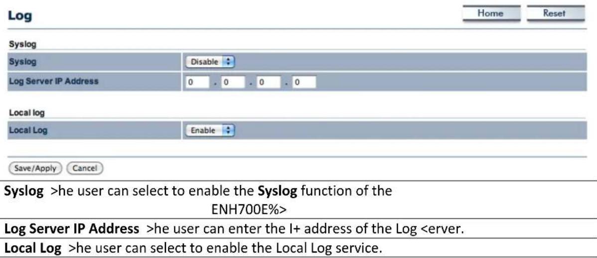
9.10 Diagnostics
he Diagnostics option in the Management section of the user interface allows users to test connection quality between the ENH700E%> and the specified client.
| Diagnostics | Home | Reset | ||
| Ping Test Parameters | ||||
| Target IP | ||||
| Ping Packet Size | 64 | Bytes | ||
| Number of Pings | 4 | |||
| Start Ping | ||||
| Traceroute Test Parameters | ||||
| Traceroute target | ||||
| Start Traceroute | ||||
| Target IP <pecify the I+ address of the client system that will be tested. | ||||
| Ping Packet Size | <pecify the size of the packets per ping. | |||
| Number of Pings | <pecify the number of pings to be tested. | |||
| Traceroute of Pings <pecify the I+ address of the client system that will be pinged back forth. | ||||
70 EnGenius Technologies Inc.: EZ Controller
he EnGenius >technologies Inc.'s EZ Controller Access +oint Management software provides a robust suite of tools for I> managers, installers and network administrators who deploy, manage and maintain wireless networks. With EZ Controller, EnGenius Wireless Indoor and Outdoor Access +oints and Client Bridges can be configured, controlled, and monitored from one central location.
For more information about the EZ Controller and for the download link, visit the EZ Controller Information page at: http://www.engeniustech.com/networking/productsdatacom/business-networking/zone-controller
70.7 EZ Controller Overview
In enhancing the real-time functionality of a network, applying the best network management software tool is necessary. With an aggressive network management tool you can perform monitoring, controlling, deploying and allocating of data that are being transmitted to different units/systems in a network. >his application helps to ensure the entire network runs without fewer faults and interruptions.
Real-time monitoring means that the requests made by the software tool to different units in a network must be executed with precision and manage simultaneously. <uch equipment includes Access +oints, Client Bridges, A+ Routers and so forth for indoor or outdoor deployments.
If you are an I> manager, installer or network administrator tasked with meeting with the growing demand of new client devices, additional users and other performance-related requirements into the network then EZ Controller can help to identify issues that can effect network performance or help to optimize the network by indicating where additional Access +oints or Client Bridges may be necessary.
70.2 Features

Users will have a visual representation of the coverage area in which all EnGenius >technology access point products (if they are compatible with the EZ Controller).

he EZ Controller has the ability to provide real time information of all the monitored devices.

he EZ Controller conveniently lists all the Access +oints with some generic information such as MAC Address or number of connected clients.
70.3 Benefits
he EZ Controller provides the following features and benefits:
• An intuitive Graphical User Interface
• Helps to optimize network performance
• Helps to minimize A+/Bridge downtime
• Monitors and controls each EnGenius A+/Bridge asset
• Monitors traffic load by A+, MAC, or I+ Address
- <sequential Firmware Upgrades to deployed Access +oints and Bridges
- Enables network administrators to import and archive maps and floor plans for radio coverage plotting
- Label assets by I+ Address, MAC Address, or manual aliases
10.4 Compatible Devices
Currently, not all EnGenius >technologies Inc. products are compatible with the EZ Controller. >he current products compatible with EZ Controller are:
- EA+150 [v. 1.2.3]
- EA+300 [v. 1.2.3]
- EA+350 [v. 1.1.0]
- ECB150 [v. 1.0.3]
- ECB300 [v. 1.0.3]
• ECB350 [v. 1.1.3] - ENH200 [v. 1.0.8]
- ENH200E%> [v. 1.0.8]
• EN>700EXT [v. 1.1.6] - ENH202 [v. 1.1.0]
- ENH500 [v. 1.1.0]
- ENH210 [v. 1.1.0]
- ENH700E%> [v. 1.1.0]
Note: As EnGenius continues to improve the products. New firmware versions and new models will continue to be released. >he above list is subject to change.
10.5 System Requirements
Currently, the system requirements of the EZ Controller require a +ersonal Computer running Windows %+, Windows Vista, or Windows 7.
Appendix A – Troubleshooting
If there are problems with the ENH700E%>, refer to the Troubleshooting section before contacting EnGenius >technologies Inc.
| >ow do I reset the EN>700EXT back to factory defaults? | >here are two ways to reset the ENH700E%>. >here is both a hardware method and a software method.Hardware Method: +ress and hold the reset button behind the hole of the +oE projector for 10 seconds. |
| <software Method: Refer to Chapter 9.5 (+age 30) on how to restore back to factory defaults. | |
| What is the default IP address of the EN>700EXT? | >he default I+ address of the ENH700E%> is 192.168.1.1 . |
| I plugged the PoE to the Ethernet port on the back of the EN>700EXT, but the unit isn't turning on, how come? | You need to connect the Ethernet cable to the +oE injector and connect the power adaptor to the DCIN port of the +oE injector. Refer to Chapter 2 (+age 8) on how to properly set up the ENH700E%> |
| When I install the PoE injector to the EN>700EXT, what kind of PoE should I use? | >he ENH700E%> uses a proprietary +oE injector and is also workable with standard 802.3af/at-compliant +oE switches. |
| What if my signal isn't strong? | Ensure that the ENH700E%> is positioned in such a way that will maximize signal radius. Refer to Chapter 2.1 (+age 8) for installation considerations. |
| Why can't I get a wireless connection? | Ensure that the encryption set on the client matches the one set up on the ENH700E%> |
Appendix B – Specification
| >ardware Specification | ||
| Standard | IEEE 802.11 a/b/g/n | |
| MCU Atheros AR7161 | ||
| RF 2 x AR9220 | ||
| Memory 64MB | ||
| Flash | 8MB | |
| Physical Interface 1 x RJ-45 for 10/100/1000 Gigabit EthernetReset Button in +oE Injector | ||
| Power Requirements | - Active Ethernet (+ower over Ethernet)- +proprietary +oE design- +ower Adapter 48V / 0.8A | |
| RF Specification | ||
| Frequency Band | 802.11a5.15 ~ 5.35GHz, 5.47 ~ 5.725GHz, 5.725~5.825GHz802.11b9gU.<., Europe and Japan product covering 2.400 to 2.484 GHz,programmable for different country regulations | |
| Data rate 300 Mbps per radio | ||
| Receive Sensitivity (Typical) 802.11n (5G>z) | 802.11n (2.4G>z) | |
| -89dBm @ MC<0 | -97dBm @ MC<0 | |
| -70dBm @ MC<7 | -78dBm @ MC<7 | |
| -89dBm @ MC<8 | -96dBm @ MC<8 | |
| -70dBm @ MC<15 -76dBm @ MC<15 | |||
| 802.11a | 802.11g | 802.11b | |
| -90dBm @ 6Mbps | -96dBm @ 6Mbps | -99dBm @ 1Mbps | |
| -72dBm @ 54Mbps | -82dBm @ 54Mbps | -93dBm @ 11Mbps | |
| Available transmit power | 802.11n (5G>z) | 802.11n (2.4G>z) | |
| 26dBm @ MC<0~2/MC<8~10 | 26dBm @ MC<0~2/MC<8~10 | ||
| 25dBm @ MC<3/MC<11 | 26dBm @ MC<3/MC<11 | ||
| 24dBm @ MC<4/MC<12 | 25dBm @ MC<4/MC<12 | ||
| 23dBm @ MC<5/MC<13 | 24dBm @ MC<5/MC<13 | ||
| 23dBm @ MC<6/MC<14 | 22dBm @ MC<6/MC<14 | ||
| 21dBm @ MC<7/MC<15 | 21dBm @ MC<7/MC<15 | ||
| 802.11a | 802.11g | 802.11b | |
| 26dBm @ 6~24Mbps | 26dBm @ 6~24Mbps | 26dBm @1~11Mbps | |
| 25dBm @ 36Mbps | 25dBm @ 36Mbps | ||
| 24dBm @ 48Mbps | 24dBm @ 48Mbps | ||
| 23dBm @ 54Mbps | 23dBm @ 54Mbps | ||
| Antenna | 4 x N-type connector | ||
| Software Specification | |||
| Operation Mode Access +oint / Client Bridge / WD< for each radio | |||
| Wireless | Auto Channel | ||
| Distance Control (802.1x Ack timeout) | |||
| Narrow Bandwidth | |||
| Multiple <<ID (4 <<ID) | |||
| VLAN Function | |||
| WD< A+ / WD< BridgeB<<ID | |||
| Security | - WE+ Encryption-64/128/152 bit- W+A/W+A2 +ersonal (W+A-+Kl+ or AE<)- W+A/W+A2 Enterprise (W+A-EA+ using >Kl+)- 802.1x Authenticator-Hide < | ||
| - Mac address filtering, up to 50 field-Wireless <>A (Client) connected list | |||
| QoS WMM | |||
| Management | |||
| Configuration Web-based configuration (H>>+)/>elnet | |||
| Firmware Upgrade Upgrade firmware via web browserFix latest setting parameter when firmware upgrading | |||
| Administrator Setting Administrator password can be changed | |||
| System monitoring | |||
| Reset Setting Reset to factory default and reboot | |||
| MIB MIB I, MIB II and +rivate MIB | |||
| SNMP V1, V2c | |||
| Backup | |||
| Environment 5 Mechanical | |||
| Temperature Range | Operating -20°C~70°C | ||
| >umidity 2non-condensing: | 0%~90% typical | ||
| Waterproof | I+68 | ||
Note: As we continue to improve our products, the specification is subject to change without notice
Appendix C – Contacting Technical Support
If the problem could not be resolved using the ENH700E%> product manual, please contact the vendor who provided the ENH700E%>. If you cannot contact your vendor, or they were unable to resolve the issue, contact the EnGenius Customer <service department.
Before you contact the EnGenius Customer <service Department, please have the following information:
• +roduct Model Name and
- Warranty Information
• >he Date of +urchase
- Firmware Version
- A Brief Description of the issue and the attempts were performed tried to resolved the issue.
Telephone: 1.888.735.7888
&-Mail: upport@EnGeniusech.com
Appendix D - #lossary
Here is a selection of terms and definitions that may help reader to be more familiar with WLAN technologies and understand the user manual better.
Ad >oc Network
A short-term WLAN framework created between two or more WLAN adapters, without going
through an Access +oint. An ad hoc network lets computers send data directly to and from one another. For an ad hoc network to work, each computer on the network needs a WLAN card installed configured for Ad Hoc mode.
Access point
A base station in a WLAN that acts as a central transmitter of data throughput and receiver of WLAN radio signals.
Antenna
A device that sends and receives radio-frequency (RF) signals. Often camouflaged on existing buildings, trees, water towers or other tall structures, the size and shape of antennas are generally determined by the frequency of the signal they manage.
Authentication
A process that verifies the identity of a wireless device or end-user. A common form of authentication is to verify identities by checking a user name and password to allow network access.
Backbone
A high-speed line or series of connections that form a major pathway within a network.
Bandwidth
he part of the frequency spectrum required to transmit desired information. Each radio channel has a center frequency and additional frequencies above and below this carrier frequency that carry the transmitted information. >he range of frequencies from the lowest to the highest used is called the bandwidth.
Bridge
A wireless device that connects multiple networks that are physically separate or use different media, but which use similar standards.
Bridge Mode
An Access +ointy in bridge mode can operate as a WLAN bridge that connects two wired network segments. >he peer device also must be in bridge mode. >his wireless bridge connection is equivalent to a Wireless Distribution <ystem (WD<).
C>AP
Challenge Handshake Authentication +rotocol. An alternative protocol that uses a challenge/response technique instead of sending passwords over the wire.
Collision
Interference resulting from two network devices sending data at the same time. >he network detects the collision of the two transmitted packets and discards both of them.
Coverage
he region within which a paging receiver can reliably receive the transmission of paging signals.
Coverage Area
he geographical area that can be served by a mobile communications network or system.
Coverage >ole
An area within the radio coverage footprint of a wireless system where the RF signal level is below the design threshold. +physical obstructions such as buildings, foliage, hills, tunnels, and indoor parking garages are usually the cause of coverage holes.
Cyclic Redundancy Check (CRC)
A common technique for detecting data transmission errors.
Dynamic >ost Configuration Protocol (D>CP)
A protocol that assigns temporary I+ addresses automatically to client stations logging onto an I+ network, so the I+ addresses do not have to be assigned manually. >he ENH210E%> contains an internal DHC+ server that automatically allocates I+ address using a user-defined range of I+ addresses.
Dead Spot
An area within the coverage area of a WLAN where there is no coverage or transmission falling off. Electronic interference or physical barriers such as hills, tunnels, and indoor parking garages are usually the cause of dead spots. <ee also coverage area.
802.11
A category of WLAN standards defined by the Institute of Electrical and Electronics Engineers (IEEE).
802.11a
An IEEE standard for WLANs that operate at 5 GHz, with data rates up to 54 Mbps.
802.11n
An IEEE standard for WLANs that operates at 2.4 GHz, with 5GHz band as option and data rate of 300 Mbps. >he new standard also raises the encryption bar to W+A2. >he 40 H> option can be added to increase the data rate.
Encryption
ranslates data into a secret code to achieve data security. >o read an encrypted file, you must have a secret key or password for decryption. Unencrypted data is referred to as plain text; encrypted data is referred to as cipher text
&SS [D
he unique identifier for an E<<. All Access +oints and their associated wireless stations in the same group must have the same E<<ID.
Footprint
Geographical areas where an entity is licensed to broadcast its signal.
#ateway
A computer system or other device that acts as a translator between two systems that use different communication protocols, data formatting structures, languages, and/or architecture.
>T mode
In the 802.11n system, two new formats, called High >hroughput (H>), are defined for the +hysical Layer, Mixed Mode, and Green Field. If a system runs 40 H>, two adjacent 20 MHz channels are used. >he larger 40 MHz bandwidth can provide better transmit quality and speed.
Keys
Like passwords, keys open (decrypt) and close (encrypt) messages. While many encryption algorithms are commonly known and public, the key must be kept secret.
Local-Area Network 2LAN3
A small data network covering a limited area, such as a building or group of buildings. Most LANs connect workstations or personal computers. LANs let many users share devices such as printers as well as data. LANs also facilitate communication through e-mail or chat sessions.
Media Access Control 2MAC3 Address
Address associated with every hardware device on the network. Every 802.11 wireless device has its own specific MAC address. >his unique identifier is hard-coded into the device and can be used to provide security for WLANs. When a network uses a MAC table, only the 802.11 radios that have their MAC addresses added to that network's MAC table can access the network.
Network Address Translation 2NAT3
An Internet standard that lets a LAN use one set of I+ addresses for internal traffic and a second set of addresses for external traffic.
Network Time Protocol 2NTP3
A protocol that lets devices synchronize their time with a time server. N>+ uses >C+ or UD+ port 123 by default.
Passphrase
A text string that automatically generates WE+ keys on wireless client adapters.
Power 'ver &thernet 2Po&3
A +oE provides power to +oE-enabled devices using an 8-pin CA> 5 Ethernet cable, eliminating the need for a power source.
Preamble
< synchronizes transmissions in a WLAN. >he preamble type defines the length of the Cyclic Redundancy Check block for communication between a device and roaming wireless stations.
Protected &xtensible Authentication Protocol 2P&AP3
Authentication protocol of IEEE 802.1x used to send authentication data and passwords over 802.11 WLANs.
Quality of Service 2QoS3
A network's ability to deliver data with minimum delay. Qo< also refers to the networking methods used to provide bandwidth for real-time multimedia applications.
Remote Authentication Dial-[n User Service 2RAD[US3
Networking protocol that provides centralized authentication, authorization, and accounting management for computers to connect and use a network service. Because of its broad support and ubiquitous nature, the RADIU< protocol is often used by I<+s and enterprises to manage access to the Internet or internal networks, WLANs, and integrated e-mail services.
Service Set [identifier 2SS[D3
Name of a WLAN. All wireless devices on a WLAN must use the same <<ID to communicate with each other.
Simple Network Management Protocol 2SNMP3
An Internet-standard protocol for managing devices on I+ networks.
Snooping
+assively watching a network for data, such as passwords, that can be used to benefit a hacker.
Temporal Key [ntegrity Protocol 2TK[P3
An encryption protocol that uses 128-bit keys. Keys are dynamically generated and distributed by the authentication server. >KI+ regularly changes and rotates encryption keys, with an encryption key never being used twice.
Transmission Control Protocol9[nternet Protocol 2TCP9[P3
A protocol that allows communications over and between networks. >C+/I+ is the basis for Internet communications.
Weighted Fair Queuing 2WFQ3
WFQ services queues are based on priority and queue weight. Queues with larger weights get more service than queues with smaller weights. >his highly efficient queuing mechanism divides available bandwidth across different traffic queues.
Wired & equivalent Privacy 2W&P3
<security protocol that provides a WLAN with a level of security and privacy comparable to that of a wired LAN. WE+ encrypts data sent between wired and WLANs to keep transmissions private.
Wireless Local-Area Network 2WLAN3
WLANs use RF technology to send and receive data wirelessly in a certain area. >his lets users in a small zone send data and share resources such as printers without using cables to physically connect each computer.
Wi-Fi Protected Access (WPA 3
A subset of the IEEE 802.11i standard. W+A applies IEEE 802.1x and Extensible Authentication +rotocol (EA+) to authenticate wireless clients using an external RADIU< database. W+A uses >emporal Key Integrity +rotocol (>KI+), Message Integrity Check (MIC), and IEEE 802.1x to encrypt data. <ee also W+A-++K (W+A -+re-<hared Key).
Wi-Fi MultiMedia (WMM3
+art of the IEEE 802.11e Qo< enhancement to the Wi-Fi standard that ensures quality of service for multimedia applications in WLANs.
Wireless Client Supplicants
<software that runs on an operating system, instructing the wireless client how to use W+A.
WPA -Pre-Shared Key (WPA-PSK3
W+A-+<K requires a single (identical) password entered into each Access +oint, wireless gateway, and wireless client. A client is granted access to a WLAN if the passwords match.
WPA2
A wireless security standard that defines stronger encryption, authentication, and key management than W+A. It includes two data encryption algorithms, >emporal Key Integrity +rotocol (>KI+) and Advanced Encryption <standard (AE<), in the Counter mode with Cipher block chaining Message authentication Code +rotocol (CCM+).
Wireless Distribution System (WDS3
A technology that lets Access +oints communicate with one another to extend the range of a WLAN.
Appendix E – Statements of Conformity
D.7 Federal Communication Commission Interference Statement
his equipment has been tested and found to comply with the limits for a Class B digital device, pursuant to +art 15 of the FCC Rules. >these limits are designed to provide reasonable protection against harmful interference in a residential installation. >his equipment generates, uses and can radiate radio frequency energy and, if not installed and used in accordance with the instructions, may cause harmful interference to radio communications. However, there is no guarantee that interference will not occur in a particular installation. If this equipment does cause harmful interference to radio or television reception, which can be determined by turning the equipment off and on, the user is encouraged to try to correct the interference by one of the following measures:
- Reorient or relocate the receiving antenna.
- Increase the separation between the equipment and receiver.
- Connect the equipment into an outlet on a circuit different from that to which the receiver is connected.
- Consult the dealer or an experienced radio/>V technician for help.
FCC Caution: Any changes or modifications not expressly approved by the party responsible for compliance could void the user's authority to operate this equipment.
his device complies with +art 15 of the FCC Rules. Operation is subject to the following two conditions: (1) >his device may not cause harmful interference, and (2) this device must accept any interference received, including interference that may cause undesired operation.
IMPORTANT NOTE:
Radiation Exposure Statement:
his equipment complies with FCC radiation exposure limits set forth for an uncontrolled environment. >his equipment should be installed and operated with minimum distance 20cm between the radiator & your body.
his transmitter must not be co-located or operating in conjunction with any other antenna or transmitter.
Note: Country selection is not available in the US model.
D.2 Industry Canada Statement
his device complies with R<<-210 of the Industry Canada Rules. Operation is subject to the following two conditions: (1) >his device may not cause harmful interference, and (2) this
device must accept any interference received, including interference that may cause undesired operation.
IMPORTANT NOTE: Radiation Exposure Statement:
his equipment complies with IC radiation exposure limits set forth for an uncontrolled environment. >his equipment should be installed and operated with minimum distance 20cm between the radiator & your body.
D.3 Europe Declaration of Conformity
his device complies with the essential requirements of the R&>>E Directive 1999/5/EC. >he following test methods have been applied in order to prove presumption of conformity with the essential requirements of the R&>>E Directive 1999/5/EC:
• EN60950-1:2006 A11:2009
• EN50385 : 2002
- Generic standard to demonstrate the compliance of electronic and electrical apparatus with the basic restrictions related to human exposure to electromagnetic fields (0 Hz - 300 GHz)
• EN 300 328 V1.7.1: 2006-10
- Electromagnetic compatibility and Radio spectrum Matters (ERM); Wideband >transmission systems; Data transmission equipment operating in the 2,4 GHz I
EN 301 489-1 V1.8.1: 2008-04
Electromagnetic compatibility and Radio <spectrum Matters (ERM); Electromagnetic Compatibility (EMC) standard for radio equipment and services; +art 1: Common technical requirements.
EN 301 489-17 V2.1.1 2009-05
Electromagnetic compatibility and Radio spectrum Matters (ERM); Electromagnetic Compatibility (EMC) standard for radio equipment and services; +art 17: <specific conditions for 2.4 GHz wideband transmission systems and 5 GHz high performance RLAN equipment
his device is a 2.4 GHz wideband transmission system (transceiver), intended for use in all EU member states and EF>A countries, except in France and Italy where restrictive use applies.
In Italy the end-user should apply for a license at the national spectrum authorities in order to obtain authorization to use the device for setting up outdoor radio links and/or for supplying public access to telecommunications and/or network services.
his device may not be used for setting up outdoor radio links in France and in some areas the RF output power may be limited to 10 mW EIR+ in the frequency range of 2454 – 2483.5 MHz. For detailed information the end-user should contact the national spectrum authority in France.
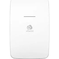
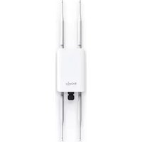
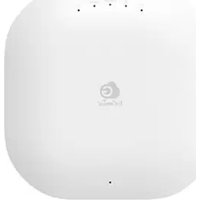
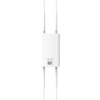
- WIRELESS OUTDOOR DUAL RADIO 802.11a/b/g/n ACCESS POINT
- Table of Contents
- About This Document ....4
- About EnGenius Technologies, Inc. 4
- Product Manual Formatting ....4
- Before You Start ....4
- Product Overview....5
- Installation and Setup....9
- Wireless Network Modes....18
- User Interface....22
- Status....23
- EnGenius Technologies Inc.: EZ ZoneController 49
- Appendix A – Troubleshooting ....52
- Appendix B – Contacting Technical Support....57
- Appendix C – Glossary....58
- Appendix D – Statements of Conformity......63
- About This -ocument
- About &n#enius Technologies, [nc.
- Product Manual Formatting
- Before You Start
- Product Overview
- Damage may occur if installing with another PoE adaptor that is not provided with the EN>700EXT.
- Contents
- Using a power adaptor other than the one included with the EN>700EXT may cause damage to the device and void the product warranty.
- Features and Benefits
- A Cost-Effective Wireless Solution to Extend and Expand an Existing Network
- >ardware Overview
- System Requirements for Installation
- Installation and Setup
- Installation Considerations
- Assembling the EN>700EXT
- Configuring a TCP9IP connection on Windows® 79Vista
- Configuring Microsoft® Windows Vista
- Configuring a TCP9IP connection on Windows® XP
- Configuring Apple® Mac OS X
- Logging onto the EN>700EXT
- Wireless Network Modes
- Access Point Mode (AP mode)
- Client Bridge Mode
- WDS Mode
- W-S :ridge Mode
- User Interface
- Status
- Save9Reload
- Save/Reload
- Unsaved changes list
- NOTE
- Main (System Information)
- 2.4G>z Wireless Client List
- 5G>z Wireless Client List
- System Log
- System
- Operation Mode
- IP Settings
- IP Settings
- Spanning Tree Settings
- 2.4G>z Wireless and 5G>z Wireless
- Access Point Mode
- Wireless Network
- SSID Profile
- Wireless MAC Filter
- Wireless Advanced Settings
- / Wireless Advanced Settings
- Client Bridge
- Wireless Network
- Wireless Advanced Settings
- Client Bridge Configuration
- WDS Mode
- WDS Station
- WDS Link Settings
- WDS Bridge Configuration
- Wireless Security Settings
- WPA-PSK, WPA2-PSK, or WPA-PSK Mixed
- WPA, WPA2, or WPA Mixed
- / SSID Profile
- WEP
- Management
- Administration
- Management VLAN
- Management VLAN Settings
- Wireless Traffic Shaping
- SNMP Settings
- Backup / Restore Settings
- Auto Reboot Settings
- Firmware Upgrade
- Firmware Upgrade
- Time Settings
- Time Settings
- Log
- Diagnostics
- EnGenius Technologies Inc.: EZ Controller
- EZ Controller Overview
- Features
- Benefits
- Compatible Devices
- System Requirements
- Appendix A – Troubleshooting
- Appendix C – Contacting Technical Support
- Appendix D - #lossary
- Ad >oc Network
- Access point
- Antenna
- Authentication
- Backbone
- Bandwidth
- Bridge
- Bridge Mode
- C>AP
- Collision
- Coverage
- Coverage Area
- Coverage >ole
- Cyclic Redundancy Check (CRC)
- Dynamic >ost Configuration Protocol (D>CP)
- Dead Spot
- 802.11
- 802.11a
- 802.11n
- Encryption
- &SS [D
- Footprint
- #ateway
- >T mode
- Keys
- Local-Area Network 2LAN3
- Media Access Control 2MAC3 Address
- Network Address Translation 2NAT3
- Network Time Protocol 2NTP3
- Passphrase
- Power 'ver &thernet 2Po&3
- Preamble
- Protected &xtensible Authentication Protocol 2P&AP3
- Quality of Service 2QoS3
- Remote Authentication Dial-[n User Service 2RAD[US3
- Service Set [identifier 2SS[D3
- Simple Network Management Protocol 2SNMP3
- Snooping
- Temporal Key [ntegrity Protocol 2TK[P3
- Transmission Control Protocol9[nternet Protocol 2TCP9[P3
- Weighted Fair Queuing 2WFQ3
- Wired & equivalent Privacy 2W&P3
- Wireless Local-Area Network 2WLAN3
- Wi-Fi Protected Access (WPA 3
- Wi-Fi MultiMedia (WMM3
- Wireless Client Supplicants
- WPA -Pre-Shared Key (WPA-PSK3
- WPA2
- Wireless Distribution System (WDS3
- Appendix E – Statements of Conformity
- D.7 Federal Communication Commission Interference Statement
- IMPORTANT NOTE:
- Radiation Exposure Statement:
- D.2 Industry Canada Statement
- IMPORTANT NOTE: Radiation Exposure Statement:
- D.3 Europe Declaration of Conformity
Brand : ENGENIUS
Model : ENH700EXT
Category : Access Point