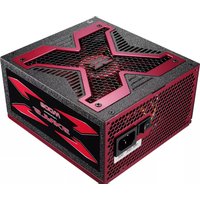
Strike-X 600W - PC Power Supply AeroCool - Free user manual and instructions
Find the device manual for free Strike-X 600W AeroCool in PDF.


| Product Type | PC Power Supply |
| Brand | AeroCool |
| Model | Strike-X 600W |
| Output Power | 600W |
| Form Factor | ATX |
| Efficiency | 80+ Bronze Certified |
| Modular Design | Non-Modular |
| Power Factor Correction | Active PFC |
| Input Voltage | 100-240V AC |
| Input Frequency | 50-60 Hz |
| Cooling Fan | 120mm |
| Main Connector | 20+4 pin |
| CPU Connector | 4+4 pin |
| PCI-E Connector | 2 x 6+2 pin |
| SATA Connector | 4 |
| Molex Connector | 2 |
| Protection Features | OVP, UVP, OCP, OPP, SCP |
| Dimensions (W x L x H) | 150 x 140 x 86 mm |
| Weight | 2.0 kg |
| Warranty | 2 years |
| Certifications | CE, FCC, RoHS |
| Maintenance | Dust cleaning recommended every 6 months |
| Repairability | Replaceable fan; warranty void if opened |
Frequently Asked Questions - Strike-X 600W AeroCool
User questions about Strike-X 600W AeroCool
0 question about this device. Answer the ones you know or ask your own.
Ask a new question about this device
Download the instructions for your PC Power Supply in PDF format for free! Find your manual Strike-X 600W - AeroCool and take your electronic device back in hand. On this page are published all the documents necessary for the use of your device. Strike-X 600W by AeroCool.
USER MANUAL Strike-X 600W AeroCool
natural_image
Red and black power supply unit with hexagonal ventilation grille and control panel (no visible text or symbols)Model Name: Strike-X 500W / Strike-X 500W [Smart Cable]
Strike-X 600W / Strike-X 600W [Smart Cable]
Strike-X 800W [Smart Cable]
Strike-X 1100W [Smart Cable]
Issue Date: 2011/08/01
Revision: A1.0
Aerocool StrikeXePower StripelyX Power Supp
DATA SHEET
Revision Change History
| Revision | Change description Date | |
| A1.0 Original 2011/08/01 | ||
1. Product Introduction
Introducing the new "Strike-X" product series from Aerocool - the ultimate gaming equipments for gamers and enthusiasts world-wide !! The "Strike-X" series includes a wide array of gaming equipments ranging from cases, PSU, fan controller, speakers, mouse, mouse pad and headsets.
Like all Strike-X products, the Strike-X power supplies bears the distinct mark of "X" such as the aluminum frame on the top cover and the label sticker design on the side of the chassis. The Strike-X power supplies were designed with the concept of "POWER", "STYLE" and "COOL" and they are perfect for those power-hungry users and yet cool enough to show off to friends.
2. Features
■ Powerful "X" theme Gaming PSU.
■ Low Noise 13.9cm Fan with intelligent fan speed control
■ High-Efficiency - 80+ Certified
■ Modular Cable w/ Black Sleeving to reduce the cable mess inside your chassis and improves the air flow of your system. (Only for modular cable models)
■ Supports Dual Core CPU, ATI CrossFire, NVIDIA SLi and all Multi-Core GPU technologies.
■ Built in next generation 6+2 pin PCI-Express graphic card connector.
■ Active Power Factor Correction (PF>0.99)
■ Extremely good voltage regulation (±5%): provides steady power input
■ High reliability: MTBF>120,000 hours
■ Green power design that meets ErP requirements
■ Protections: Over Current, Over Voltage, Over Power, Over Temperature, Under Voltage and Short-Circuit protection
■ Safety / EMI Approvals: CE, FCC, TUV, Gost, CB.
3. AC Input and DC Output Specification
■ Strike-X 500W
| AC Input | 230VAC 15A 50-60Hz | ||||
| Output Voltage | 3.3V | 5V | +12V | -12V | 5Vsb |
| Min. Output Current | 0.5A | 0.5A | 1A | 0A | 0.1A |
| Max. Output Current | 24A | 24A | 41A | 0.5A | 2.5A |
| Max. Combined Wattage | 150W | 492W | 6W 12.5W | ||
| Total Continuous Wattage | 500W | ||||
■ Strike-X 600W
| AC Input | 230VAC 15A 50-60Hz | ||||
| Output Voltage | 3.3V | 5V | +12V | -12V | 5Vsb |
| Min. Output Current | 0.5A | 0.5A | 1A | 0A | 0.1A |
| Max. Output Current | 24A | 24A | 50A | 0.5A | 3A |
| Max. Combined Wattage | 150W | 600W | 6W 15W | ||
| Total Continuous Wattage | 600W | ||||
■ Strike-X 800W
| AC Input | 115-230VAC 15A 50-60Hz | ||||
| Output Voltage | 3.3V | 5V | +12V | -12V | 5Vsb |
| Min. Output Current | 0.8A | 0.5A | 0A | 0A | 0.1A |
| Max. Output Current | 24A | 24A | 66A | 0.5A | 3A |
| Max. Combined Wattage | 170W | 792W | 6W | 15W | |
| Total Continuous Wattage | 800W | 21W | |||
■ Strike-X 1100W
| AC Input | 100-240VAC 13A 50-60Hz | ||||
| Output Voltage | 3.3V | 5V | +12V | -12V | 5Vsb |
| Min. Output Current | 0.8A | 0.5A | 0A | 0A | 0.1A |
| Max. Output Current | 24A | 30A | 90A | 0.5A | 3A |
| Max. Combined Wattage | 170W | 1080W | 6W | 15W | |
| Total Continuous Wattage | 1100W | 21W | |||
4. Output Voltage Regulation
| Output Voltage | MIN | Nominal | MAX | Units | Range |
| +5V | 4.75 | 5.00 | 5.25 | Volts | ±5% |
| +12V 1/12V2 | 11.40 | 12.00 | 12.60 | Volts | ±5% |
| -12V | -10.80 | -12.00 | -13.20 | Volts | ±10% |
| +3.3V | 3.14 | 3.30 | 3.47 | Volts | ±5% |
| +5Vs | 4.75 | 5.00 | 5.25 | Volts | ±5% |
5. Efficiency versus Load
| Strike-X 500/600W Efficiency | |||
| Loading | 100% | 50% | 20% |
| Efficiency | 82% | 85% | 82% |
| PFC | ≥q 0.9 -- | -- | |

| Strike-X 800W Efficiency | |||
| Loading | 100%Load | 50%Load | 20%Load |
| Efficiency | 82% | 85% | 82% |
| PFC | ≥q 0.9 | -- | -- |
| Strike-X 1100W Efficiency | |||
| Loading | 100%Load | 50%Load | 20%Load |
| Efficiency | 82% | 85% | 82% |
| PFC | ≥q 0.9 | -- | -- |

6. DC Output Ripple & Noise
| Parameter | Ripple + Noise | Units |
| +5V 50 mV | ||
| +12V1 120 mV | ||
| +12V2 120 mV | ||
| -12V 120 mV | ||
| +3.3V 50 mV | ||
| +5Vsb 50 mV |
7. Output Protection
7.1 Over Voltage Protection
The +5V/+12V/+3.3V DC output are protected against the over voltage condition. Maximum value can't be over 6.5V at 5V terminal and 15.5V at 12V, 4.3V at 3.3V.
7.2 Over-Current Protection
Current protection should be designed to limit the current to operate within safe operating conditions. Over current protection schemes where only the voltage output that experiences the over current event is shut off may be adequate to maintain safe operation of the power supply and the system; however, damage to the motherboard or other system components may occur. The recommended over current protection scheme is for the power supply to latch into the shutdown state. The setting of over current protection for each output rail is as following.
7.3 Over Power Protection
The power supply will be shutdown and latch off when output power is 105%\~150%.
7.4 Over-Temperature Protection
This power supply includes an over-temperature protection sensor, which can trip and shut down the power supply at 110^ C
7.5 Under voltage protection
In an under voltage fault occurs, the supply will latch all DC outputs into a shutdown state when +12V,+5V & +3.3V outputs under 60% of it's maximum value.
7.6 Short Circuit Protection
Short circuit placed on +5V,+12V,+3.3V,-12V will latch off. +5VSB will auto-recovery.
8. Environmental Requirements
6.1 Operating / Storage Temperature Range
Operating ambient : 0°C min to +40°C max Non operating ambient : -20°C to +60°C
6.2 Humidity (non condensing)
Operating ambient : 10% to 90% relative humidity Non operating ambient : 5% to 95% relative humidity
6.3 Altitude
Operating ambient : 0 to 10,000 ft
Non operating ambient : 0 to 50,000 ft
9. Safety Certificate
| Certificate | Mark | Description |
| CB |  | Global Certification by IECEE |
| FCC |  | Federal Communication Commission |
| CE |  | Certification Europe |
| TUV |  | Certification forGERMANY |
| GOST |  AB 57 AB 57 | Russian Certification |
10. Output Connectors / Pin Description
The output connector pin assignments should follow the arrangements as shown in the table below.
| Main Power Connector | |||||
| Pin | Signal | Wire | Pin | Signal | Wire |
| 1 +3.3VDC Orange 13 +3.3VDC | [+3.3V sense] | Orange [Brown] | |||
| 2 +3.3VDC Orange 14 -12VDC | Blue | ||||
| 3 COM | Black | 15 COM Black | |||
| 4 +5VDC Red 16 PS_ON# Green | |||||
| 5 COM Black 17 COM Black | |||||
| 6 +5VDC Red 18 COM Black | |||||
| 7 COM Black 19 | COM | Black | |||
| 8 PWR_OK | Gray | 20 | Reserved | NC | |
| 9 +5VSB | Purple | 21 | +5VDC | Red | |
| 10 + | 12VDC1 Yellow 22 +5 | VDC Red | |||
| 11 1 | 2VDC1 Yellow 23 5VDC Red | ||||
| 12 + | 3.3VDC Orange 24 + | COM Black | |||
| +12V Power Connector | ||||||
| Pin | Signal | Wire | Pin | Signal | Wire | |
| 1 | COM | Black | 5 | +12VDC1 | Yellow/ Blue | |
| 2 | COM | Black | 6 | +12VDC1 | Yellow/ Blue | |
| 3 | COM | Black | 7 | +12VDC2 | Yellow/ Blue | |
| 4 | COM | Black | 8 | +12VDC2 | Yellow/ Blue | |
| Peripheral Connector(s) | Floppy Drive Connector | ||||
| Pin | Signal | Wire | Pin | Signal | Wire |
| 1 | +12VDC1 | Yellow | 1 +5 | VDC Red | |
| 2 | COM | Black | 2 | COM | Black |
| 3 | COM | Black | 3 | COM | Black |
| 4 | +5VDC | Red 4 +1 | 2VDC1 | Yellow | |
| Series ATA Connector | |||||
| Pin | Signal | Wire Pin | Signal | Wire | |
| 1 | +12V1 | Black | 4 | COM | Yellow |
| 2 | COM | Black | 5 | +3.3V | Yellow |
| 3 | +5V | Black | - | - | - |
| PCI-E 6pin Power Connector | |||||
| Pin Signal | Wire | Pin | Signal | Wire | |
| 1 | +12VDC1/2 | Yellow | 4 | COM | Black |
| 2 | +12VDC1/2 | Yellow | 5 | COM | Black |
| 3 | +12VDC1/2 | Yellow | 6 | COM | Black |
| PCI-E 6+2pin Power Connector | |||||
| Pin Signal | Wire | Pin | Signal | Wire | |
| 1 | +12VDC1/2 | Yellow | 5 | COM | Black |
| 2 | +12VDC1/2 | Yellow | 6 | COM | Black |
| 3 | +12VDC1/2 | Yellow | 7 | COM | Black |
| 4 | COM | Black | 8 | COM | Black |
| Main24(20+4)PinConnector | Peripheral Connector(4 Pin) | Floppy Connector(4 Pin) | S-ATA Connector(15 Pin) | |
| +3.3V 1 | 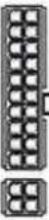 13 +3.3V 13 +3.3V | |||
| +3.3V 2 | 14 -12V | |||
| COM 3 | 15 COM | |||
| +5V 4 | 16 PS_ON | |||
| COM 5 | 17 COM | +12V | +12V | |
| +5V 6 | 18 COM | COM | COM | |
| COM 7 | 19 COM | COM | COM | |
| PG 8 | 20 NC | +5V | +5V | |
| 5VΔ 9 | 21 +5V | |||
| +12V 10 | 22 +5V | |||
| +12V 11 | 23 +5V | |||
| +3.3V 12 | 24 COM | |||
| PCI-E Connector (6Pin) | PCI-E Connector (6+2Pin) | ATX12V 4 Pin Connector | EPS12V 8Pin Connector |
 |  |  | 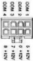 |
11. Cable Configuration
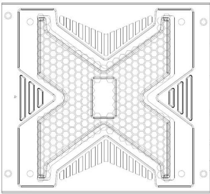
natural_image
Technical line drawing of a symmetrical mechanical component with hexagonal lattice structure (no text or symbols)

[Smart Cable Models]

natural_image
Technical line drawing of a mechanical component with hexagonal lattice structure (no text or symbols)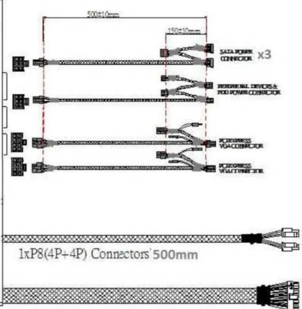
1 x 20+4-Pin Motherboard Connector 500mm


natural_image
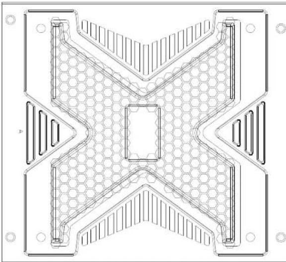
Technical line drawing of a symmetrical mechanical component with hexagonal lattice structure (no text or symbols)
1 x 20+4-Pin Motherboard Connector

natural_image
Technical line drawing of a symmetrical mechanical or architectural component with hexagonal lattice pattern and mounting holes (no text or symbols)
1 x 20+4-Pin Motherboard Connector 700mm
80 PLUS Verification and Testing Report
| TYPICAL EFFICIENCY (50% Load): | 86.06% |
| AVERAGE EFFICIENCY : | 84.54% |
| 80 PLUS COMPLIANT: | YES |

natural_image
Red and black electronic device with visible internal components (no readable text or symbols)| Ecos ID # | 1171.1 |
| Manufacturer | Aerocool |
| Model Number | STRIKE-X500 |
| Serial Number | N/A |
| Year | 2008 |
| Type | ATX12V |
| Test Date | 12/2/2008 |
| Rated Specifications | Value | Units |
| Input Voltage | 115-230 Volts | |
| Input Current | 10/6 Amps | |
| Input Frequency | 50/60 Hz | |
| Rated Output Power | 500 Watts |
Note: All measurements were taken with input voltage at 115 V nominal and 60 Hz.
line
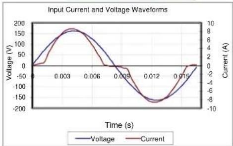
| Time (s) | Voltage (V) | Current (A) | | -------- | ----------- | ----------- | | 0.000 | 0 | 0 | | 0.003 | 150 | 8 | | 0.006 | 100 | 4 | | 0.009 | -50 | -2 | | 0.012 | -150 | -8 | | 0.015 | 0 | 0 |Input AC Current Waveform (ITHD = 31.44%, 50% Load)
| I_RMS A | PF | I_THD (%) | Load(%) | Fractionof Load | InputWatts | DC Terminal Voltage (V)/ DC Load Current (A) | OutputWatts | Efficiency% | ||||
| 12V (cumulative of 12V1, 12V2, etc.) | -12V | 3.3V | 5V* | 5VSB | ||||||||
| 1.09 | 0.96 | 25.75% | 20% | Light | 120.46 | 11.3/0.1 | 3.3/2.4 | 5.1/1.6 | 5212/68101.99 | |||
| 2.70 | 0.95 | 31.44% | 50% | Typical | 294.32 | 11.3/0.2 | 3.3/5.9 | 5.1/4 | 512/2/2683.28 | |||
| 5.46 | 0.97 | 24.96% | 100% | Full | 607.35 | 12.1/33.6 | 503.44 | 82.89% | ||||

line
| Loading (% of Rated Output Power) | Input Watts (Watts) | Output Watts (Watts) | | --------------------------------- | ------------------- | -------------------- | | 20% | 100.00 | 100.00 | | 50% | 300.00 | 250.00 | | 100% | 600.00 | 500.00 |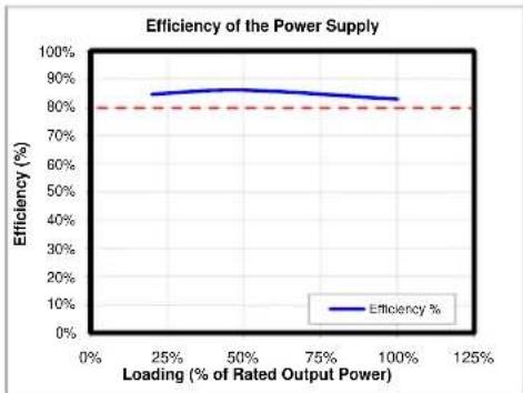
line
| Loading (% of Rated Output Power) | Efficiency (%) | | --------------------------------- | -------------- | | 25% | 85% | | 50% | 86% | | 75% | 84% | | 100% | 82% |
PLUG LOAD solutions
These tests were conducted by a third party independent testing firm on behalf of the 80 PLUS Program. 80 PLUS is a certification program to promote highly-efficient power supplies (greater than 80% efficiency in the active mode) in technology applications. http://www.80plus.org/

80 PLUS Verification and Testing Report
| TYPICAL EFFICIENCY (50% Load): | 86.87% |
| AVERAGE EFFICIENCY : | 85.19% |
| 80 PLUS COMPLIANT: | YES |
natural_image
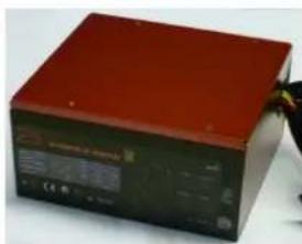
Red and black electronic device with visible control panel and display (no readable text or symbols)| Ecos ID # | 1169.2 |
| Manufacturer | Aerocool |
| Model Number | STRIKE-X600 |
| Serial Number | N/A |
| Year | 2008 |
| Type | ATX12V |
| Test Date | 12/1/2008 |
| Rated Specifications | Value | Units |
| Input Voltage | 115-230 Volts | |
| Input Current | 12/8 Amps | |
| Input Frequency | 50/60 Hz | |
| Rated Output Power | 600 Watts |
Note: All measurements were taken with input voltage at 115 V nominal and 60 Hz.
line
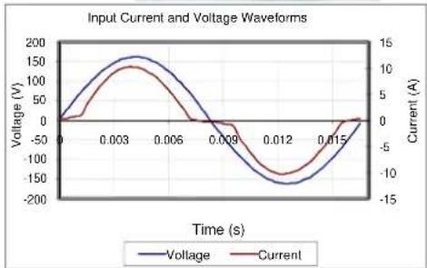
| Time (s) | Voltage (V) | Current (A) | | -------- | ----------- | ----------- | | 0.000 | 0 | 0 | | 0.003 | 150 | 10 | | 0.006 | 100 | 5 | | 0.009 | 0 | 0 | | 0.012 | -150 | -10 | | 0.015 | 0 | 0 |Input AC Current Waveform (ITHD = 30.55%, 50% Load)
| I_RMS A | PF | I_THD (%) | Load(%) | Fractionof Load | InputWatts | DC Terminal Voltage (V)/ DC Load Current (A) | OutputWatts | Efficiency% | ||||
| 12V (cumulative of 12V1, 12V2, etc.) | -12V | 3.3V | 5V* | 5VSB | ||||||||
| 1.28 | 0.97 | 1.86% | 20% | Light | 142.10 | 11.1/0.1 | 3.3/2.4 | 5.1/1.6 | 52.2/8.4 | 22.39 | ||
| 3.20 | 0.95 | 30.55% | 50% | Typical | 349.32 | 11.1/0.2 | 3.3/6 | 5.1/415.1/2.2 | 303.46 | |||
| 6.51 | 0.97 | 24.42% | 100% | Full | 724.50 | 11.9/41.9 | ||||||

line
| Loading (% of Rated Output Power) | Input Watts (Watts) | Output Watts (Watts) | | --------------------------------- | ------------------- | -------------------- | | 20% | 150.00 | 150.00 | | 50% | 350.00 | 350.00 | | 100% | 750.00 | 750.00 |
line
| Loading (% of Rated Output Power) | Efficiency (%) | | --------------------------------- | -------------- | | 0% | 80% | | 25% | 85% | | 50% | 87% | | 75% | 86% | | 100% | 83% |
PLUG LOAD solutions
These tests were conducted by a third party independent testing firm on behalf of the 80 PLUS Program. 80 PLUS is a certification program to promote highly-efficient power supplies (greater than 80% efficiency in the active mode) in technology applications. http://www.80plus.org/

80 PLUS Verification and Testing Report
TYPICAL EFFICIENCY (50% Load):
88.66%
AVERAGE EFFICIENCY :
87.14%
80 PLUS COMPLIANT:
YES
natural_image
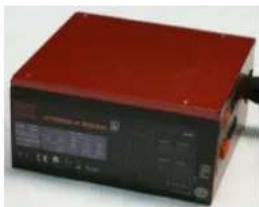
Red and black electronic device with control panel and display (no visible text or symbols)| Ecos ID # | 893.1 |
| Manufacturer | Aerocool |
| Model Number | STRIKE-X800 |
| Serial Number | NA |
| Year | 2008 |
| Type | ATX12V |
| Test Date | 9/22/2008 |
| Rated Specifications | Value | Units |
| Input Voltage | 100-240 Volts | |
| Input Current | 9-5 Amps | |
| Input Frequency | 50-60 Hz | |
| Rated Output Power | 800 Watts |
Note: All measurements were taken with input voltage at 115 V nominal and 60 Hz.

line
| Time (s) | Voltage (V) | Current (A) | | -------- | ----------- | ----------- | | 0.000 | 0 | 0 | | 0.003 | 150 | 12 | | 0.006 | 100 | 8 | | 0.009 | -50 | -4 | | 0.012 | -150 | -12 | | 0.015 | -50 | -4 | | 0.018 | 0 | 0 |Input AC Current Waveform (ITHD = 20.7%, 50% Load)
| I_RMS A | PF | I_THD (%) | Load(%) | Fractionof Load | InputWatts | DC Terminal Voltage (V)/ DC Load Current (A) | OutputWatts | Efficiency% | ||||
| 12V (cumulative of 12V1, 12V2, etc.) | -12V | 3.3V | 5V* | 5VSB | ||||||||
| 1.70 0.98 | 17.17% | 20% | Light | 192.45 | 12/0.1 3.3/1.8 5/1.8 5/019.36/1.86 | 85.30% | ||||||
| 4.10 0.98 | 20.70% | 50% | Typical | 461.55 | 12/0.2 3.3/4.5 5/4.5 5/112.30/2.51 | 88.66% | ||||||
| 8.26 0.99 | 14.75% | 100% | Full | 938.50 | 12.2/59.5 | 12.1/0.4 3.3/9 | 5/9 4.9/2.6 820.93 | 87.47% | ||||

line
| Loading (% of Rated Output Power) | Input Watts (Watts) | Output Watts (Watts) | | --------------------------------- | ------------------- | -------------------- | | 20% | 200.00 | 200.00 | | 50% | 400.00 | 400.00 | | 100% | 900.00 | 900.00 |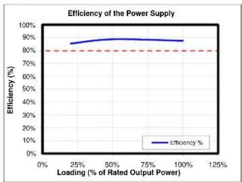
line
| Loading (% of Rated Output Power) | Efficiency (%) | | --------------------------------- | -------------- | | 0% | 80% | | 25% | 85% | | 50% | 88% | | 75% | 87% | | 100% | 86% |
PLUG LOAD
solutions
These tests were conducted by a third party independent testing firm on behalf of the 80 PLUS Program. 80 PLUS is a certification program to promote highly-efficient power supplies (greater than 80% efficiency in the active mode) in technology applications. http://www.80plus.org/

80 PLUS Verification and Testing Report
| TYPICAL EFFICIENCY (50% Load): | 90.09% |
| AVERAGE EFFICIENCY : | 88.48% |
| 80 PLUS COMPLIANT: | YES |

natural_image
Red and black electronic device with control panel and display (no visible text or symbols)| Ecos ID # | 2637 |
| Manufacturer | Aerocool |
| Model Number | STRIKE-X1100 |
| Serial Number | N/A |
| Year | 2011 |
| Type | ATX12V |
| Test Date | 6/30/2011 |
| Rated Specifications | Value | Units |
| Input Voltage | 115-230 Volts | |
| Input Current | 15 Amps | |
| Input Frequency | 0.00 Hz | |
| Rated Output Power | 1100 Watts |
Note: All measurements were taken with input voltage at 115 V nominal and 60 Hz.

line
| Time (s) | Voltage (V) | Current (A) | | -------- | ----------- | ----------- | | 0.003 | 150 | 8 | | 0.006 | 140 | 7 | | 0.009 | 120 | 6 | | 0.012 | 80 | 4 | | 0.015 | 0 | 0 |Input AC Current Waveform (ITHD = 5.65%, 50% Load)
| I_RMS A | PF | I_THD (%) | Load(%) | Fractionof Load | InputWatts | DC Terminal Voltage (V)/ DC Load Current (A) | OutputWatts | Efficiency% | ||||
| 12V (cumulative of 12V1, 12V2, etc.) | -12V | 3.3V | 5V | 5Vsb | ||||||||
| 2.26 | 0.99 | 8.85% | 20% | Light | 256.60 | 11.7/0 | 3.4/2.3 | 5/2.9 | 5.2/0.8/3.8/5.62 | |||
| 5.44 | 1.00 | 5.65% | 50% | Typical | 623.70 | 11.7/0.1 | 3.4/5.7 | 5/7.1 | 5/12/2.8/5.8/1.90 | |||
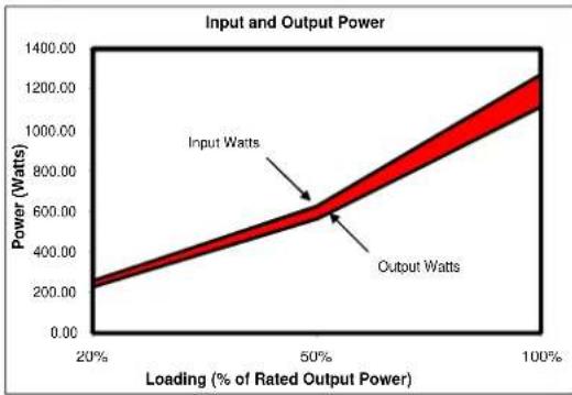
| 11.09 | 1.00 | 3.94% | 100% | Full | 1274.50 | 12.2/81.7 | 1114.10 | 87.41% | ||||
line
| Loading (% of Rated Output Power) | Input Watts (Watts) | Output Watts (Watts) | | --------------------------------- | ------------------- | -------------------- | | 20% | 200.00 | 200.00 | | 50% | 600.00 | 600.00 | | 100% | 1200.00 | 1200.00 |
line
| Loading (% of Rated Output Power) | Efficiency (%) | | --------------------------------- | -------------- | | 0% | 80% | | 25% | 85% | | 50% | 90% | | 75% | 88% | | 100% | 85% |
PLUG LOAD
solutions
These tests were conducted by a third party independent testing firm on behalf of the 80 PLUS Program. 80 PLUS is a certification program to promote highly-efficient power supplies (greater than 80% efficiency in the active mode) in technology applications. http://www.80plus.org/


- Aerocool StrikeXePower StripelyX Power Supp
- Product Introduction
- Features
- AC Input and DC Output Specification
- ■ Strike-X 600W
- Output Voltage Regulation
- Efficiency versus Load
- DC Output Ripple & Noise
- Output Protection
- Over Voltage Protection
- Over-Current Protection
- Over Power Protection
- Over-Temperature Protection
- Under voltage protection
- Short Circuit Protection
- Environmental Requirements
- Operating / Storage Temperature Range
- Humidity (non condensing)
- Altitude
- Safety Certificate
- Output Connectors / Pin Description
- Cable Configuration
- PLUS Verification and Testing Report
- PLUG LOAD solutions
- PLUG LOAD
- solutions
Brand : AeroCool
Model : Strike-X 600W
Category : PC Power Supply