
CBM-920 - Printer CITIZEN - Free user manual and instructions
Find the device manual for free CBM-920 CITIZEN in PDF.


| Product Type | Impact Dot Matrix Printer |
| Model | CBM-920 (24 columns / 40 columns) |
| Dimensions (W x H x D) | 115 mm x 65 mm x 119 mm |
| Weight | Approx. 500 g (incl. mounting brackets) |
| Power Supply | DC 5V ±5%, 2.5A (printing), 4A peak |
| Power Consumption | Approx. 7 VA (printing), 0.7 VA (standby) |
| Printing Method | Dot matrix, single-direction print |
| Character Configuration | (5+1)×8 dots (24 cols) / (4+0.5)×8 dots (40 cols) |
| Number of Columns | 24 columns (144 dots/line) or 40 columns (180 dots/line) |
| Printing Speed | Approx. 2.5 lines/sec (24 cols) / 1.8 lines/sec (40 cols) |
| Character Size | 1.62×2.4 mm (24 cols) / 1.08×2.4 mm (40 cols) |
| Line Pitch | 3.52 mm |
| Paper Type | Roll paper, width 57.5±0.5 mm, outer diameter 50 mm, inner core φ12±1 mm |
| Interface | Serial RS-232C or Parallel (Centronics) |
| Input Buffer | 2K bytes |
| Ink Ribbon | Purple, replaceable cassette |
| Auto Loading | Yes (can be disabled via DIP switch) |
| Paper End Detection | Paper near end and paper end sensors |
| Self-Test Print | Yes, by holding LF switch while powering on |
| Hex Dump Mode | Available on 40 columns model only |
| International Characters | Selectable via DIP switch (8 countries) or command (9 countries) |
| Operating Temperature | 0°C to 40°C |
| Storage Temperature | -20°C to 60°C |
| Safety Standards | EN60950, EN55022 Class A, FCC Class A, UL/CSA |
| Accessories Included | Roll paper, ribbon cassette, interface cable, mounting bracket, screws, wire, manual |
Frequently Asked Questions - CBM-920 CITIZEN
User questions about CBM-920 CITIZEN
0 question about this device. Answer the ones you know or ask your own.
Ask a new question about this device
Download the instructions for your Printer in PDF format for free! Find your manual CBM-920 - CITIZEN and take your electronic device back in hand. On this page are published all the documents necessary for the use of your device. CBM-920 by CITIZEN.
USER MANUAL CBM-920 CITIZEN
Declaration of Conformity
This printer conforms to the following Standards:
Low Voltage Directive 73/23/EEC, 93/68/EEC and the EMC Directive 89/336/EEC, 92/31/EEC, 93/68/EEC.
LVD : EN60950
EMC: EN55022
Class A
EN61000-3-2
EN61000-3-3
EN55024
This declaration is applied only for 230V model.
Warning: This is a Class A products. In a domestic environment this product may cause radio interference in which case the user may be required to take adequate measures.
IMPORTANT SAFETY INSTRUCTIONS
- Read all of these instructions and save them for future reference.
• Follow all warnings and instructions marked on the product. - Unplug this product from the wall outlet before cleaning. Do not use liquid or aerosol cleaners. Use a damp cloth for cleaning.
• Do not use this product near water. - Do not place this product on an unstable cart, stand or table. The product may fall, causing serious damage to the product.
- Slots and openings on the back or bottom of the case are provided for ventilation. To ensure reliable operation of the product and to protect it from overheating, do not block or cover these openings. The openings should never be blocked by placing the product on a bed, sofa, rug of other similar surface. This product should never be placed near or over a radiator or heater. This product should not be placed in an built-in installation unless proper ventilation is provided.
- This product should be operated from the type of power source indicated on the marking label. If you re not sure of the type of power available, consult your dealer or local power company.
- Do not allow anything to rest on the power cord. Do not place this product where the cord will be walked on.
- If an extension cord is used with this product, make sure that the total of the ampere ratings of the products plugged into the extension cord does not exceed the extension cord ampere rating. Also, make sure that the total of all products plugged into the wall outlet does not exceed 15 amperes.
- Never push objects of any kind into this product through cabinet slots as they may touch dangerous voltage points or short out parts that could result in a risk of fire or electric shock. Never spill liquid of any kind on the product.
- Except as explained elsewhere in this manual, do not attempt to service this product by yourself. Opening and removing the covers that are marked “Do Not Remove” may expose you to dangerous voltage points or other risks. Refer all servicing on those compartments to service personnel.
Unplug this product from the wall outlet and refer servicing to qualified service personnel under the following conditions:
A. When the power cord or plug is damaged or frayed.
B. If liquid has been spilled into the product.
C. If the product has been exposed to rain or water.
D. If the product does not operate normally when the operating instructions are followed. Adjust only those controls that are covered be the operating instructions since improper adjustment of other controls may result in damage and will often require extensive work by a qualified technician to restore the product to normal operation.
E. If the product has been dropped or the cabinet has been damaged.
F. If the product exhibits a distinct change in performance, indicating a need for service.
IMPORTANT: This equipment generates, uses, and can radiate radio frequency energy and if not installed and used in accordance with the instruction manual, may cause interference to radio communications. It has been tested and found to comply with the limits for a Class A computing device pursuant to Subpart J of Part 15 off FCC Rules, which are designed to provide reasonable protection against such interference when operated in a commercial environment. Operation of this equipment in a residential area is likely to cause interference, in which case the user at his own expense will be required to take whatever measures may be necessary to correct the interference.
CAUTION: Use shielded cable for this equipment.
Sicherheitshinweis
This digital apparatus does not exceed the class A limits for radio noise emissions from digital, apparatus, as set out in the radio interference regulations of the Canadian department of communications.
- Before using the equipment, be sure to read this User's manual thoroughly.
- Portions of the contents of this User's manual may be changed without prior notice.
- The reproduction of part or all of the contents of this User's manual without permission is strictly forbidden.
- Absolutely do not carry out maintenance, disassembly, or repair of parts that are not specified in this User's manual.
- Note that losses, which may be attributed to the customer's wrong operation method or usage environment, will be outside the responsibility of this company.
- Do not carry out operations other than those explained in this User's manual, since doing so may become a cause of accidents or breakdowns.
- Because data is basically transient, long-period and permanent storage of data will not be possible. Please note in advance that this company will not be responsible in any way for losses or lost profits caused through the clearing of data due to breakdowns, repairs, investigations, etc.
- If any questionable points, mistakes, omitted explanations, etc. are found in the contents of this document, please notify this company.
- Please note that notwithstanding the conditions in above 8, this company will not be responsible for the consequences of results obtained through operation of this equipment.
- Please make sure to conduct maintenance before using this equipment after long-term storage.
CAUTIONS FOR SAFE USE (Be sure to follow these cautions)
The cautions that must be followed in order to prevent injury to persons using this equipment or to other persons, and to protect against damage to property are displayed as shown below.
- The danger of injury or damage resulting from mistaken methods of use and not following the displayed cautions will be explained as follows:

WARNING!
The WARNING symbol indicates that if the methods of use is mistaken by not following the explanation given, there will be a possibility of the occurrence of death or serious injury.

CAUTION
The CAUTION symbol indicates that if the methods of use is mistaken by not following the explanation given, there will be a possibility of the occurrence of problems or physical damage.

The symbol represents an illustration shown to attract reader's attentions.

The symbol represents an illustration shown the information like method etc...

WARNING!
- Absolutely do not carry out the following actions, because those may cause the breakage of printer, abnormality in operation, the heating or smoking cause fire or electric shock. In situation where the equipment has been damaged (No printing, no paper feeding etc.....), the equipment is making smoke, creating some offensive smell or noise, switch off the power, remove the power supply cable and interface cable, contact your sales shop.

WARNING!
- Do not subject this equipment to excessive force or shocks such as by treading on it, dropping it or hitting it.
- Do not install this equipment in locations with poor ventilation, and do not use the equipment in such way that the ventilation port is obstructed.
- Do not use this equipment in locations such as laboratories in which chemical reaction takes place, or in locations in which the air includes salt or toxic gases.
- Do not use this equipment at voltage other than the specified voltage or at frequencies other than at the specified frequencies.
- Do not insert or remove the power cables or interface cable by pulling on the cable, and do not carry the main unit in such way as to subject the cables to force.
- Do not drop or insert foreign subjects like paper clips or split pins, etc. into the equipment. In case of dropping those foreign object into the equipment, remove power supply plug and contact your sales shop.
- Do not arrange the power cable so that many plugs are using same power outlet. Do not use the equipment in the situation where there is any breakage on the power supply cable or electrical contact of the cables is not proper.
- Do not spill drinks such as tea, coffee or juice, or spray anti-mosquito preparations, etc. onto the equipment. In case of spilling drinks like water, switch off the power, remove power supply cable and contact your sales shop.
- Do not attempt to disassemble or modify this equipment, since these actions will cause fire or electric shock.

PRECAUTIONS FOR INSTALLATION
- Do not install or store this printer near fire, water, a heater, in the direct sunshine in the locations such as high-temperature, high humidity, oily and dusty. This may cause fire and abnormality.
- Do not use this printer in locations such as laboratories in which chemical reactions take place, or in locations in which the air includes salt or toxic gases. This may cause a fire or electric shock.
• Make sure to install this printer on the vertical mounting panel with no vibration. - Do not use this printer in the locations have environment to cause a trouble in operations.
- Do not put anything on the printer unit. This may cause a breakage.
- To fix this printer, make sure to use enclosed rack mounting bracket and screws. Do not fasten the screws excessively. This may cause abnormality and breakage.
- Do not use this printer near radio or television, and do not use same outlet as the one used for radio and television. This may cause a trouble with receiving an electric wave.
- Do not use voltage or power supply other than specified in this manual. Do not use this printer in case + side and GND are not connected properly. This may cause breakage and a fire.
• Make sure that capacity of the power supply connected to this printer is enough before using this printer. - Absolutely do not connect the earth with gas pipe. This may a possibility of explosion. Make sure to remove the power plug from power outlet in case of connect or disconnect the earth.
- Make sure to connect or disconnect the cable holding the main body of connectors after switching off the both power of this equipment and the equipment which this equipment is connected to.
- Certainly connect the connector cables. Especially, if the polarity is connected in reverse way, this may cause the damage to the internal parts or to the equipment, which this equipment is connected to.
- To avoid data transmission error due to noise, make sure not to use too many extension power supply cables, or not to connect the other equipment creates much noise with this single line.

CAUTION FOR HANDLING
Do not carry out the following operation, since they may be cause of breakage.
- Do not carry out blank printing in the condition where there is no recording paper and no ink ribbon in the unit, this may make a damage to print head.
- Do not drop any foreign subjects like paper clips, or splits pins, etc. into the printer unit.
• Do not spill any drinks or chemical liquid onto the printer units. - Do not subject this equipment to excessive force shocks such as by treading on it, dropping it or hitting it.
- Do not operate the operation panel using sharp objects such as the top of a pen etc.
- Do not pull the paper in printer forcibly by hand or pull the paper in opposite way to paper feed direction.
- Change ink ribbon cassette before the ink of this ribbon completely runs out. In case the ribbon is teared by the excess in use, this may cause the abnormality in printing. Do not supply the ink with this ribbon cassette.
- Do not carry the printer unit setting the ribbon cassette in printer.
To avoid injury and prevent damage from spreading.
• Do not touch the printing portion of print head.
- During operation, do not touch moving parts such as gears, or the electrical parts in side the printer units.
• Take care not to injure yourself or other objects from the edge of the sheet metal.
- If an abnormality occurs during use, immediately stop using the printer and remove the power cable from the power source outlet.
- If a breakage occurs, do not attempt to disassemble the equipment. Be sure to leave the repair of this equipment to Service personnel.
• Take care not to put your hands or fingers between the panel during opening and closing the panel.

ORDINARY MAINTENANCE
• Make sure to maintain the equipment after switching OFF the power.
- When cleaning the platen of printer mechanism, wipe out the dirty portion by a cotton pad dipped into ethyl alcohol.
- When cleaning the surface of the main unit case, use soft cloth. In case the dirty portion can not be cleared out by the soft cloth, use wet cloth squeezed tightly. Absolutely do not use thinners, truculence, benzene or ketene group solvents, or chemical-impregnated cleaning cloths.
- At least, leave cleaning of the inside of this equipment to your sales shop once a year. Using this equipment keeping dirty without cleaning the inside may cause a fire or breakage of the equipment.
CONTENTS
1. OUTLINE....8
1.1 Features....8
1.2 Accessories 8
2. GENERAL SPECIFICATIONS....9
2.1 Model classifications....9
2.2 Power Supply 9
2.3 Cautions for Roll Paper....9
2.4 Specification ....10
3. OUTER APPEARANCE AND EXPLANATION OF EACH PART....11
3.1 Outer Appearance and Explanation of Each Part....11
3.2 Explanation of Each Part....12
4. OPERATION....13
4.1 Rack Mounting....13
4.2 Power Supply Connection....14
4.3 Panel Opening/Closing 15
4.4 Paper Feeding....16
4.5 Setting Ribbon Cassette ....16
4.6 Setting Printing Paper 17
4.7 Self-Printing Function....19
4.8 Paper Near End Sensor, Paper End Sensor, and Mechanical Alarm....20
4.9 Auto Loading Function 21
5. PARALLEL INTERFACE....22
5.1 Specifications....22
5.2 Connector Pin's Configuration....22
5.3 Explanation of Input/Output Signals....23
5.4 Electrical Characteristics....24
6. SERIAL INTERFACE....26
6.1 Specifications....26
6.2 Connector Connection Diagram....27
6.3 Explanation of Input/Output Signals....27
6.4 Electrical 28
6.5 Error Detection....29
7. DIP SWITCH SETTING....31
8. PRINT CONTROL FUNCTION....32
8.1 Control code list....32
8.2 Input data format....33
9. CHARACTER SET 48
9.1 Japanese character code table....48
9.2 International character code table 49
9.3 Character code table....50
10. OUTLINE DRAWING....52
1. OUTLINE
CBM-920 is an Impact Dot Matrix printer used for various data communication, POS terminal and various systems. CBM-920, a compact type printer with rated into a rack, etc., can serve to print, on in serial or parallel mode. Prior to actual use, please read this instruction carefully for your correct understanding.
1.1 Features
- Ultra small-sized rack mounting dot matrix printer
- Extremely light weight
- High speed printing
- Paper end detecting function
- Auto loading function
- Conforming to RS-232C and Centronics
- 24 columns model and 40 columns
- A number of initialization function
1.2 Accessories
This set, besides the printer main unit, contains the following accessories:
Roll paper (· 1)
Ribbon cassette (· 1)
I/F cable (· 1)
Rack mounting bracket (· 1)
Screw for mounting (· 2)
Wire (· 1)
Instruction Manual (· 1)
2. GENERAL SPECIFICATIONS
2.1 Model classifications
| CBM-920- | 24 | 40 | RP | F |
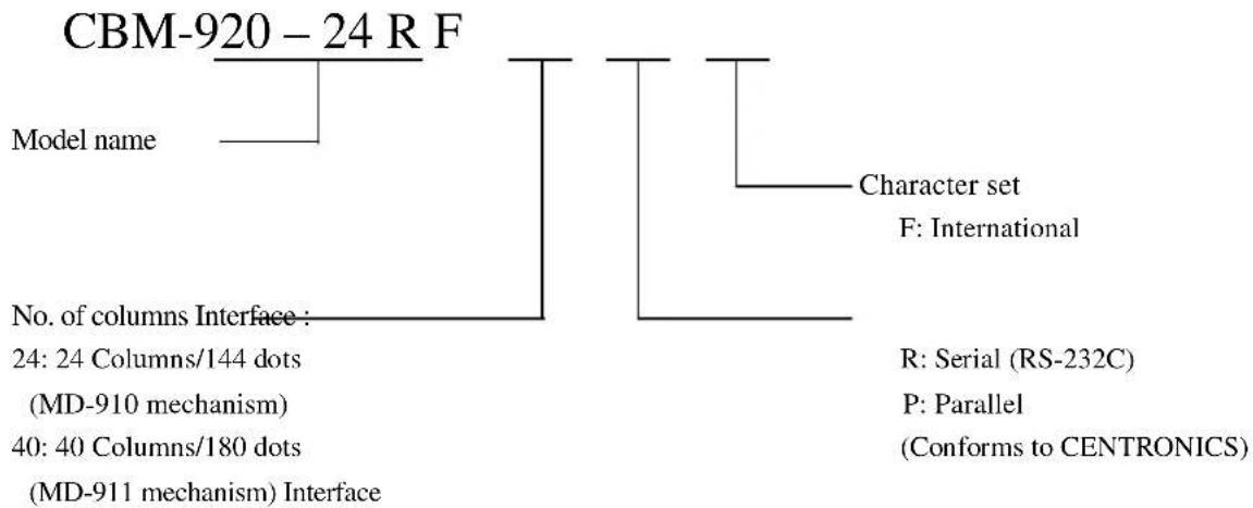
flowchart
graph TD
    A["CBM-920 - 24 R F"] --> B["Model name"]
    A --> C["Character set"]
    C --> D["F: International"]
    A --> E["No. of columns Interface:"]
    E --> F["24: 24 Columns/144 dots (MD-910 mechanism)"]
    E --> G["40: 40 Columns/180 dots (MD-911 mechanism) Interface"]
    C --> H["R: Serial (RS-232C)"]
    C --> I["P: Parallel (Conforms to CENTRONICS)"]
2.2 Power Supply
Prepare power supply having voltage of +5V and current capacity of 2.5A or more.
2.3 Cautions for Roll Paper
Appearances: Make sure that the beginning of roll paper to the inner core must be as follows.
- No fold. Paper must be rolled into the inner core
- No flap
- Do not paste the paper to the core. (If an inner core is available)

Recommended paper:
One ply paper..... 45 \~ 55 Kg/1000 pcs/1091 x 788 mm
2 ply paper .... No carbon paper Original paper (34 Kg paper)+copy paper 1 pcs (34 Kg paper)
Total thickness 0.13 mm or less
2.4 Specifications
| ITEM CBM-920-24 | ** CBM-920-40** | ||
| 1 Printing method Dot matrix method | |||
| 2 | Printing direction | Single-direction print (normal character/inverted character) | |
| 3 Character configuration | (5 + 1) · 8 | (4 + 0.5) · 8 | |
| 4 No. of columns 24 columns: 144 dots/line 40 columns: 180 dots/line | |||
| 5 | Printing speed | Approx. 2.5 line/sec. | Approx. 1.8 line/sec. |
| 6 Character size | 1.62 · 2.4 mm | 1.08 · 2.4 mm | |
| 7 Line pitch | 3 | 52 mm | |
| 8 | Paper | Roll paper 57.5 ± 0.5 (W) · 50 (D)mmInner diameter φ12 ± 1 mm | |
| 9 | Interface | Serial interface (RS232C) or parallel interface (Centronics) | |
| 10 | Input buffer | 2K byte | |
| 11 | Paper near end detection | When print paper goes to the near to end, the data receiving is stopped. And then printing is stopped after printing the data in the buffer. | |
| 12 | Auto loading | When new paper is set into Paper inlet of Mechanism paper is automatically fed. | |
| 13 | International character codes | Character of 8 different countries is available by DIP switch setting.(Japan/U.S./France/Germany/U.K/Italy/Spain/Denmark)By command setting, above countries plus additional one (Sweden) can be set. | |
| 14 Ink ribbon Purple | |||
| 15 | Supply voltage | DC5V ± 5% (printing voltage) Approx. 2.5AApprox. 4A (duty 10%) at peakUse external power supply. | |
| 16 | Average power consumption | At printing: Approx. 7 VAAt no printing: Approx. 0.7VA | |
| 17 | Weight | Approx. 500g (incl. mounting brackets) | |
| 18 | External dimensions | 115 (W) · 65 (H) · 119 (D) mm | |
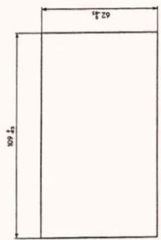
| 19 | Fitting hole dimensions | 109 (W) · 62 (H) _0.5 mm | |
| 20 | Operating temperature | 0 ~ 40°C | |
| 21 | Storage temperature | -20 ~ 60°C | |
| 22 | Safety and EMI StandardApplied(EMI is measured with packaged power supply) | For Europe: Safety StandardTUV: EN60950: 1992 + A1 + A2 + 1993For North America: EMIFCC class ASafety StandardUL: USR UL/950 - 3thC-UL: CNR CAN/CSA C22.2 No. 550-95 | |
3. OUTER APPEARANCE AND EXPLANATION OF EACH PART
3.1 Outer Appearance and Explanation of Each Part
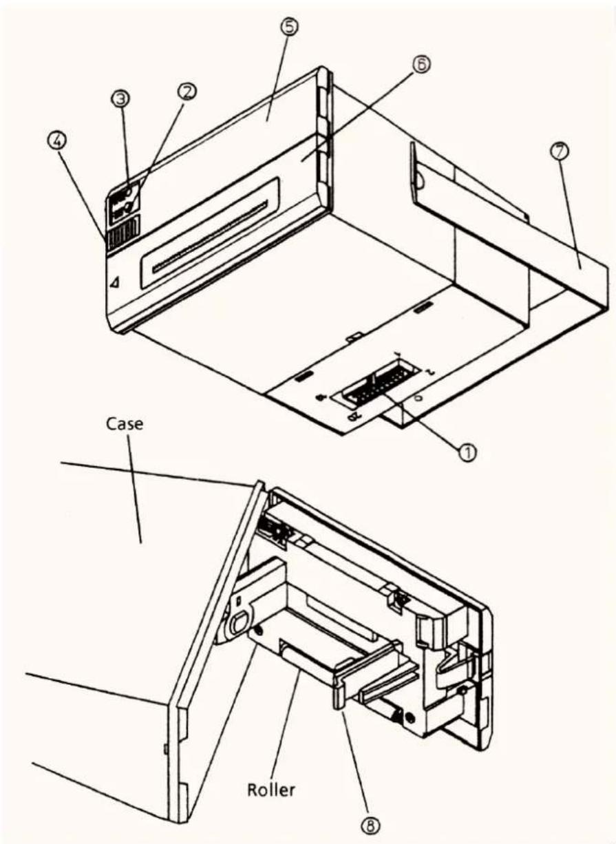
3.2 Explanation of Each Part
①Interface Connector Connected to various hosts via cables. On connection, confirm beforehand that power supply of the host and the printer are OFF. The power cable, also, is held in this connector.
Make sure to connect FG terminal with an earth. Do not connect this terminal with the lines except for an earth.
② Feed Switch With this switch pressed, paper is fed. Use this to insert paper and to put space. With pushing this switch, power is turned ON, self-print function is conducted.
③ Paper Lamp Lights up when paper has become scarce or run out. (Only when Paper Near End/Paper End function has been set.) Put out when paper has been inserted.
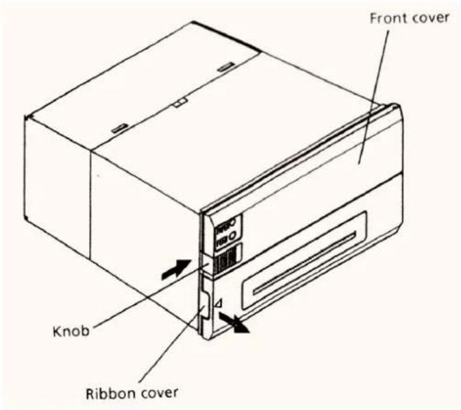
④ Knob Use this to set paper or to open the front cover on changing of paper.
⑤ Front Cover Open/close this on setting or changing of paper.
⑥ Ribbon Cover Open/close this to change ink ribbon.
This opens when the left side of the front face is pulled forward.
⑦ Mounting bracket Use this to fix the main body to a rack, etc.
⑧ Paper Holder Paper setting section. Placing paper from the insertion port, set paper.
4. OPERATION
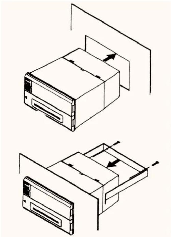
4.1 Rack Mounting
(1) As in the following drawing, insert the main body into the rack.
(2) Inserting the main body on the rear side with mounting bracket, fasten the ma in body with the screws. Pay attention not to tighten screws excessively.
(3) After fixing, confirm opening/closing of the front panel, etc..
(4) In fastening screws, do not fasten the screws until the main body is deformed. This may be an abnormal force o the ma in body as well as be an cause of breakage.
(5) The thickness of rack panel to fix the main body is to be approx. 1\~3 mm.
natural_image
Technical line drawing of a device with two views showing internal components and directional arrows (no text or symbols)4.2 Power Supply Connection
(1) Confirm that the main power supply, etc. are OFF.
(2) Prepare power supply satisfying the power voltage and current capacity having been specified in the specifications.
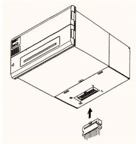
(3) Firmly connect, in appropriate direction, the power supply and the main body through using the attached cable. The connector is at the bottom of the main body as shown in the drawing. This cable is integrated with the communication cable. The power cable is larger than the communication cable, which is colored in red and in orange for +5V use and in black for GND.
(4) Connect a power supply cable to the power supply. Pay attention not to connect power supply cable in reverse polar.
natural_image
Technical line drawing of an electronic device with a connector pin inserted into a housing (no text or symbols)4.3 Panel Opening/Closing
4.3.1 Opening/Closing of Front Panel
(1) Applying your finger on the projection on the left side of the front panel, pull it forward when the lock is released. It opens by about 180^ centering around the fixed axis.
(2) For closing, pressing the front panel, tightly close it until click sound is heard. Also, confirm, on closing, that paper is free of slackening.
4.3.2 Opening/Closing of Ribbon Cover
(1) When paper is out of the front cover, cut it off.
(2) Applying your finger on the dent on the left side of the ribbon cover, pull it forward. It opens by about 180^ centering around the fixed axis.
(3) For closing, pressing the ribbon cover, close it tightly.
4.4 Paper Feeding
With the LF switch pressed once, paper is fed by one line.
Paper is fed while it is continuously pressed.
To feed paper, do not pull it forcibly. Use the LF switch.
During pressing the LF switch, the data can not be received.
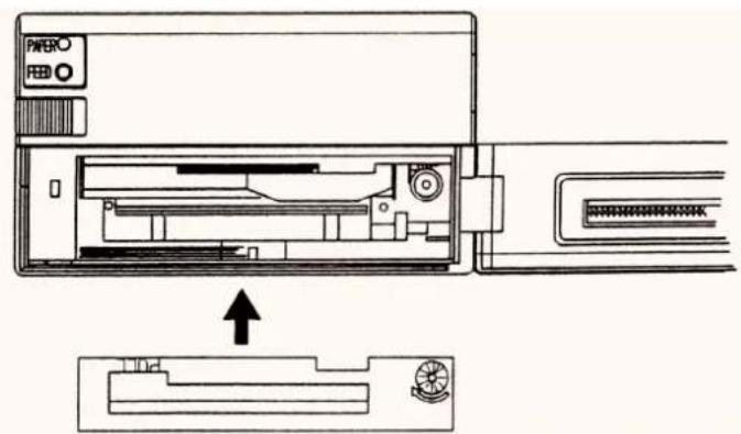
4.5 Setting Ribbon Cassette
(1) Open the ribbon cover. Be sure to turn off power before opening it.
(2) In case the paper is out from front cover, cut the paper or remove this paper.
(3) Confirming the correct direction of a new ribbon cassette, insert ribbon between the printing head and the platen and press cassette down from the knob side.
(4) Turning the ribbon cassette knob in the arrowed direction, remove slack.
(5) On replacing a ribbon cassette, pull it out as holding the "PULL" part.

REMARK
- In case the ribbon cassette is kept setting in printer so long time, there may be the case to make a paper dirty.
And in case of continuous printing under low temperature, light print may be occurred due to the characteristic of the ink.
• Do not conduct printing with no ribbon cassette, this may damage a print head.
- Replace ribbon cassette before wearing out completely.
- Use exclusive ribbon cassette.
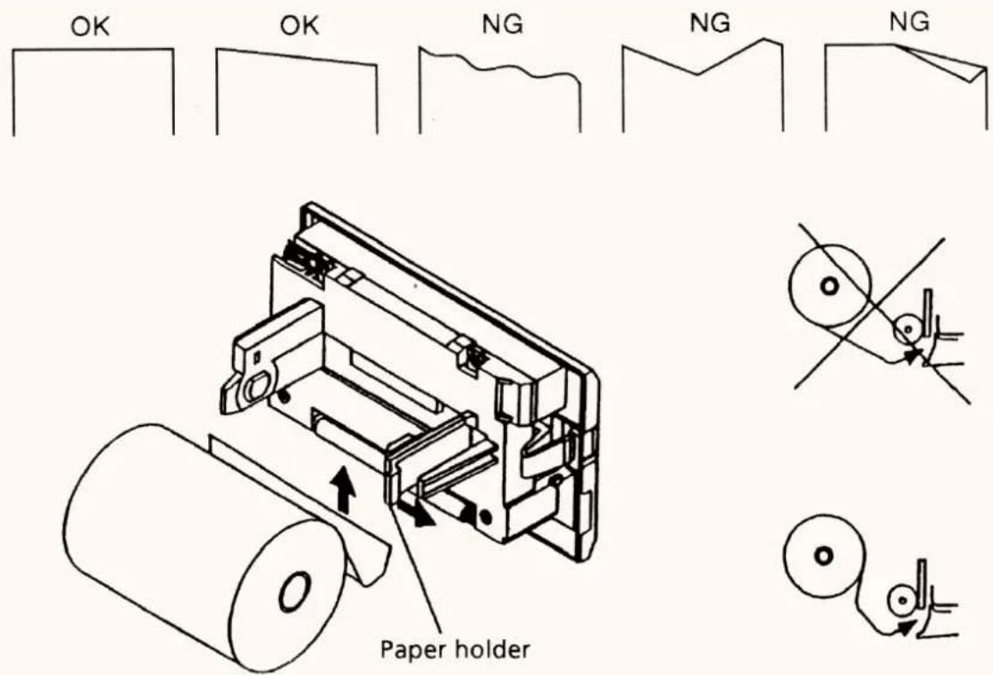
4.6 Setting Printing Paper
(1) Open the front cover.
(2) Cut the edge of Printing Paper as the following drawing.
(3) Insert the paper into the paper insertion of the printer mechanism.
When auto loading function is specified, paper is loaded automatically.
When auto loading function is not specified, push the LF switch until the paper enters the printer mechanism.
(4) By holding the paper holder in the arrowed direction, insert paper roll and make sure paper holder hold the core.
(5) Eliminating slack on the printing paper, close the front panel.
(6) To change paper, as holding the paper holder in the arrowed direction, re-move the core. Remove, at this time, excessive paper by using the LF switch.
After setting the paper, press LF switch once.
Then, printer goes to data input printing mode.

REMARK
- Keep the paper winding direction correct.
• While in replacing of paper, do not send data from host terminal.
• Do not pull the paper in reverse direction of paper feed. This may cause abnormality of print head. - In case the paper is fed diagonally in paper supplying side or paper removing side, paper jam may occur. In this case, turn OFF the power switch immediately and pull out the excessive paper slowly at straight direction.
4.7 Self-Printing Function
(1) Test Printing By supplying power as pushing the LF switch, the characters for use, ROM version, DIP switch setting, and model name can be printed.
After test printing, perform ordinary operation.
By sending RESET signals as pushing the LF switch, perform test printing.
During self printing, BUSY signal is being outputted.
In this test printing, the following information is printed.
1) Specified country for international character
2) CR + LF function
3) Direction of print character
4) Communication condition (Serial interface only)
(2) Hex decimal dump mode
In this mode, all of the data sent from the host is printed at Hex decimal code. In case that the data of last line is not enough for one line, the data of last line is printed by pressing LF switch.
This mode can be available by turning ON the Dip Switch DS1-8.
After Power is ON (after printing, if self print is conducted), this mode is available.
This mode can be kept until Power is OFF.
To change to normal print mode, turn Power OFF after turning Dip switch DS 1-8 OFF, and then turn Power ON.
This function is only available for 40 columns model.
This function is not available for 24 columns model.
Example of printing at dump mode. (40 columns model)
| 31 | 32 | 33 | 34 | 35 | 36 | 37 | 38 | 1 2 3 4 5 6 7 8 |
| 39 | 3A | 3B | 3C | 3D | 3E | 3F | 40 | 9*+、-。/@ |
| 41 | 42 | 43 | 44 | 45 | 46 | 47 | 48 | ABCDEFGH |
| 49 | 4A | 4B | 4C | 4D | 4E | 4F | 50 | IJKLMNOP |
| 51 | 52 | 53 | 54 | 55 | 56 | 57 | 58 | QRSTUVWX |
4.8 Paper Near End Sensor, Paper End Sensor, and Mechanical Alarm
4.8.1 Paper Near End
When the paper is getting low, the paper near end is detected and printing is stopped. Power supply to the printing solenoid and motor is immediately stopped and BUSY PE signals are outputted to the host.
When data still exists in the input buffer, the remaining data in the buffer is printed before stopping.
Discharge remaining paper with the LF switch, set new paper and push the LF switch. Then normal print mode is created after cancellation of BUSY and PE output.
This function can be selected by Dip Switch setting.
4.8.2 Paper End
Whether there is printing paper or not is detected. With printing paper running out, printing stops and BUSY and PE signal is outputted.
Printing is also stopped even when data remains in the input buffer.
Discharge paper with the LF switch, set new paper and push LF switch. Then BUSY PE is canceled.
When auto loading function is available, printer automatically feeds recording paper at a few lines by inserting the recording paper into the paper inlet.
4.8.3 Mechanical Alarm
When occurrence of trouble in the mechanism is judged by locking of the motor, power supply to the printing solenoid and motor is stopped and BUSY signals as well as FAULT signals are output to host terminal.
To recover from alarm state, after removing trouble causes, either re-supply power or input RESET signals.
For severe trouble, turn power off and leave this repair to service personnel.
4.9 Auto Loading Function
This printer is equipped with function which can automatically load paper. With paper inserted, it is automatically fed by a few lines. When printing paper is diagonally or not properly fed, take out paper softly and insert it once again.
If not using this function, cancel this with the DIP switch. Paper insertion is, then, performed with the LF switch.
After paper is inserted, with the LF switch pressed and detached, print ready state is created.
5. PARALLEL INTERFACE
5.1 Specifications
1) Data input method: 8 bit parallel method (DATA 1 \~ 8)
2) Control signal: ACK, STB, BUSY, RESET, FAULT, PE
3) Power supply cable: +5V, GND, and FG
4) Applicable connector: Printer side: HIF3F-20PA-2.54DS (HIROSE)
Cable side: HIF3C-20D-2.54C (HIROSE)
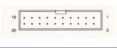
5.2 Connector Pin's Configuration
| PIN | SIGNAL NAME | PIN | SIGNAL NAME |
| 1 | 11 | BUSY | |
| 2 | DATA 1 | 12 | PE |
| 3 | DATA 2 | 13 | |
| 4 | DATA 3 | 14 | |
| 5 | DATA 4 | 15 | GND |
| 6 | DATA 5 | 16 | FG |
| 7 | DATA 6 | 17 | +5V (for circuit) |
| 8 | DATA 7 | 18 | GND |
| 9 | DATA 8 | 19 | +5V (for mechanism) |
| 10 | 20 | GND |
5.3 Explanation of Input/Output Signals
1) Input Signals into Printer
DATA 1 ...... 8 bit parallel signal (positive logic)
DATA 2 ...... 8 bit parallel signal (positive logic)
DATA 3 ...... 8 bit parallel signal (positive logic)
DATA 4 ...... 8 bit parallel signal (positive logic)
DATA 5 ...... 8 bit parallel signal (positive logic)
DATA 6 ...... 8 bit parallel signal (positive logic)
DATA 7 ...... 8 bit parallel signal (positive logic)
DATA 8 ...... 8 bit parallel signal (positive logic)
...... Strobe signal to read 8 bit data (negative logic)
RESET ...... Signal to reset the whole printer (negative logic)
4msormore
2) Output Signals from Printer
ACK.... 8 bit data request signal (negative logic)
BUSY ...... Signal to show BUSY state. Input new data at "LOW" (positive logic)
PE..... Signal to indicate shortage of paper (positive logic)
FAULT..... Signal to indicate occurrence of trouble, such as mechanical al arm (positive logic)
3) Timing Chart
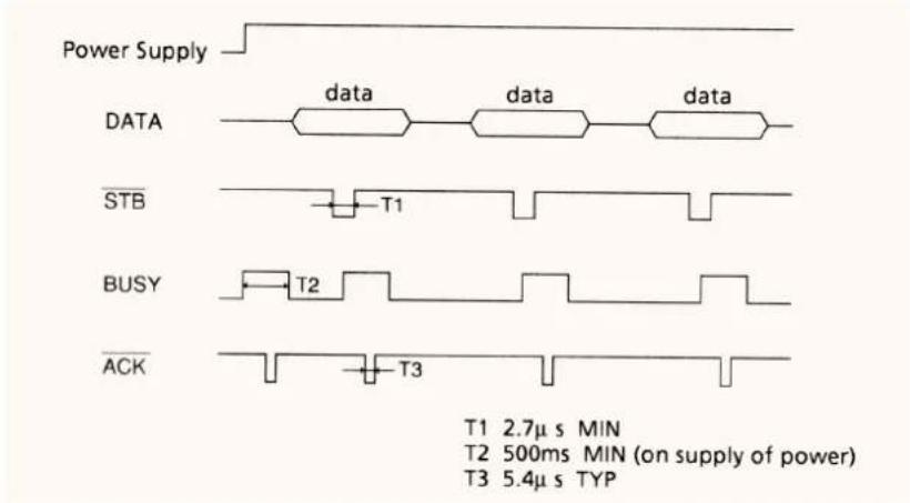
5.4 Electrical Characteristics
1) Input Signal Level
The input signal level is HCMOS.
"HIGH" level : 4.0V MIN
"LOW" level : 1.0V MAX
2) Output Signal Level
BUSY signal level is HCMOS. Other signals are sent at TTL level.
For HCMOS level
"HIGH" level : 4.0V MIN
"LOW" level : 1.0V MAX
For TTL level
"HIGH" level : 2.4V MIN
"LOW" level : 0.4V MAX
3) I/O Conditions
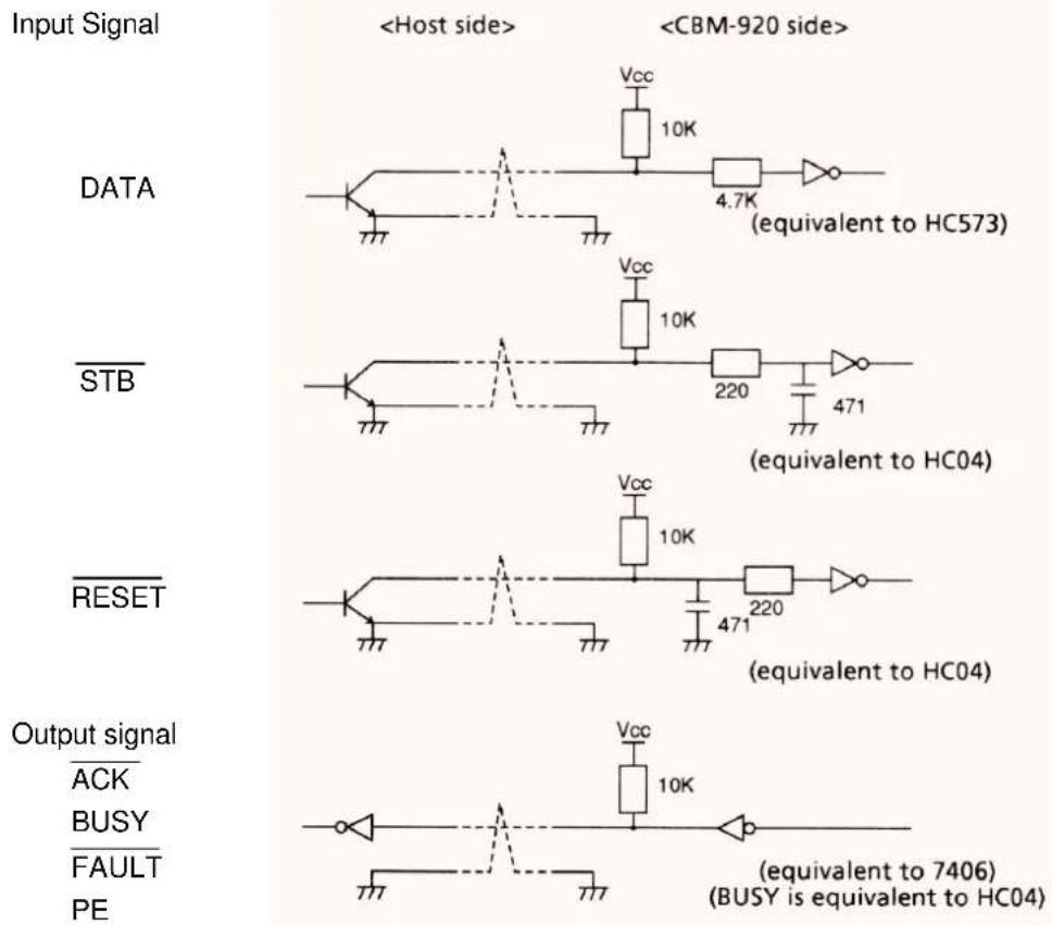
other
| Input Signal | DATA | STB | RESET | | ------------ | ---- | --- | ----- | |6. SERIAL INTERFACE
6.1 Specifications
1) Synchronization system : Asynchronous system
2) Baud rate : 1,200/2,400/4,800/9,600BPS (selectable by user)
3) 1 -word configuration : Start bit : 1 bit
: Data bit : Stop bit 7 or 8 bits (selectable by user)
: Parity bit : Odd, even, no parity (selectable by user)
: Stop bit : 1 bit or more
4) Data I/O signals : R · D, T · D (RS-232C)
5) Control signals : DTR, RESET, FAULT, PE
6) Signal polarity : RS232C (Mark: logic "1"(-3V \~ -12V) Space logic "0"(+3V \~ +12V) TTL, CMOS (H level: logic "1" L level: logic "0"
7) Power cable : +5V,GND and FG
8) Applicable connector : Printer side: HIF3F-20PA-2.54DS (HIROSE)
Cable side: HIF3C-20D-2.54C (HIROSE)
6.2 Connector Connection Diagram
| PIN SIGNAL NAME PIN SIGNAL | NAME | ||
| 1 ~ 8 N.C | (not connected) 15 GND | ||
| 9 | R · D | 16 FG | |
| 10 | T · D | 17 +5V(for circuit) | |
| 11 DTR | 18 GND | ||
| 12 PE | 19 +5V(for mechanism) | ||
| 13 | FAULT | 20 GND | |
| 14 RESET | |||
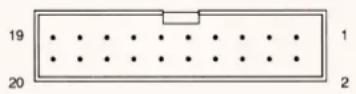 | |||
6.3 Explanation of Input/Output Signals
1) I/O Signals into Printer (RS-232C)
• T · D (TRANSMIT DATA)
Serial transmit data signals
• R · D (RECEIVE DATA)
Serial received data signals.
• DTR (DATA TERMINAL READY)
When this signal is in Ready (space), send data or a command.
If sending takes place in Busy (mark), overrun error is occurred.
Even in printing, data can be sent into the input buffer. If this signal is in Ready.
Further, Busy takes place also on supply of power, in test printing, on-line status or on occurrence of resetting.
2) Input Signals into Printer
RESET..... Signal to reset the whole printer (negative logic) 4 ms or more
3) Output Signals from Printer
PE ...... Signal to indicate shortage of paper (positive logic)
FAULT ...... Signal to indicate occurrence of trouble such as mechanical alarm (positive logic)
4) Data Configuration
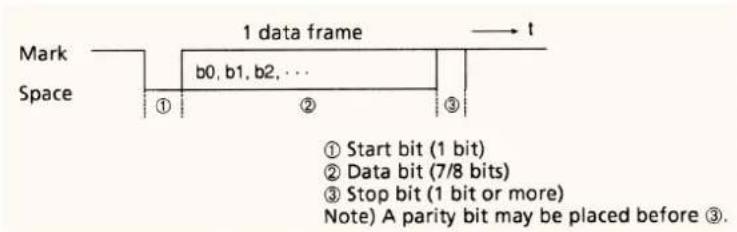
6.4 Electrical Characteristics
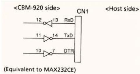
1) RS232C I/O signals (R · D, T · D, DTR)
Input (R · D) Mark = (-8V) : stop bit Output (T · D) Space = (+8V) : start bit Output (DTR) Mark = (-8V) : stop bit
Space = (+8V) : start bit
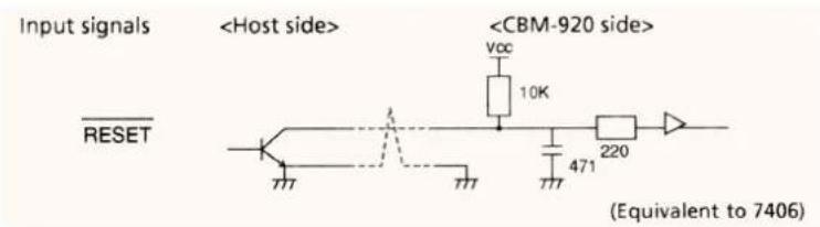
2) Input Signal Level (RESET)
The input signal level is at TTL.
"HIGH" level : 2.4V MIN
"LOW" level : 0.4V MAX
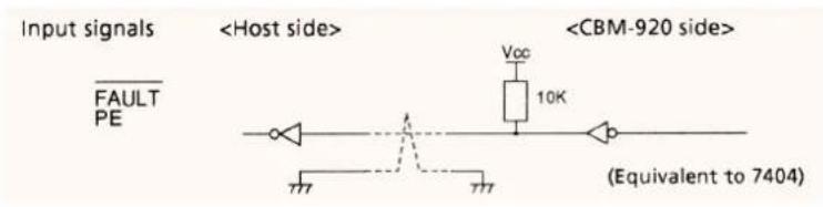
3) Output Signal Level (FAULT, PE)
The output signal level is at TTL.
For TTL level
"HIGH" level : 2.4V MIN
"LOW" level : 0.4V MAX
6.5 Error Detection
- Communication Error
1) Parity Error In checking of odd/even parity based on parity checking assignment, when parity is found nonconforming.
2) Framing Error In detection of stop bit when space state has been detected.
3) Overrun Error Regardless of data being held in receiving buffer register, when next data are transmitted to the receiving buffer register.
On occurrence of the above mentioned error, the data concerned is converted into '■' (7FH) which is printed.
• Receiving Control and Buffering
The CBM-920, on receiving of print data, performs receiving control (DTR control) in one-word unit. At this time, when the host side has performed data transmit as ignoring DTR, overrun of received data can take place. This state should be avoided by the host side on its own responsibility. (No follow-up can be applied to a data effluent type host.)
7. DIP SWITCH SETTING
DS1
| Switch No. | Function OFF ON Factory Setting | |||
| 1 | International character See the table below | * | ||
| 2 | * | |||
| 3 | * | |||
| 4 CR function CR ignored | CR+LF OFF | |||
| 5 | Character direction | Erecting character | Inverted character | OFF |
| 6 | Paper near end function | Enabled | Disabled | OFF |
| 7 | Auto loading function | Enabled | Disabled | OFF |
| 8 | Hex. Dump mode | Disabled | Enabled | OFF |
* changes in setting according to destination.
Hex. Dump mode is not available with 24 columns version.
International Character Setting
| Switch No. \ International Character Setting | U.S | France | Germany | U.K | Denmark | Italy | Spain | Japan |
| 1 | OFF | ON | OFF | ON | OFF | ON | OFF | ON |
| 2 | OFF | OFF | ON | ON | OFF | OFF | ON | ON |
| 3 | OFF | OFF | OFF | OFF | ON | ON | ON | ON |
DS2
| Switch No. | Function | OFF | ON | Factory Setting |
| 1 | Bit length | 8 bits | 7 bits | OFF |
| 2 | Parity | No | Yes | ON |
| 3 | Parity conditions | Odd Even | OFF | |
| 4 | Baud rate | S e e t h e t a b l e b e l o w . | OFF | |
| 5 | ON | |||
Baud Rate (bps) Setting
| Switch No. | 1,200 | 2,400 | 4,800 | 9,600 |
| 4 | OFF | ON | OFF | ON |
| 5 | OFF | OFF | ON | ON |
* DS2 setting is available only for Serial interface
8. PRINT CONTROL FUNCTION
8.1 Control code list
| Character | CODE | Function |
| LF 0A Line | feed after printing | |
| CR 0D Line | feed after printing | |
| SI 0F Specifying standard character | ||
| SO 0E Specifying double wide character | ||
| US 1F Specifying standard character | ||
| RS 1E Specifying double wide character | ||
| CAN | 18 | Data cancellation |
| DC2 12 | Specifying inverted character | |
| DC1 | 11 | Initial setting |
| ESC + "B" | 1B, 42 | Specifying continuous paper feed |
| ESC + "R" | 1B, 52 | Specifying international character |
| ESC + " / " | 1B, 2F | Registration of sentence |
| ESC + " ! " | 1B, 21 | Printing registered sentence |
| ESC + "&" | 1B, 26 | Defining the download character |
| ESC + "%" | 1B, 25 | Download character valid / invalid |
| ESC + "K" | 1B, 4B | Bit image printing |
| FS + "W" + 1 | 1C, 57,1 | Specifying double wide and double high character |
| FS + "W" + 0 | 1C, 57, 0 | Cancellation of double wide and double high character |
8.2 Input data format
(1) Line feed command after printing (CR, LF)
By inputting of CR (0DH) code, printer prints the data in print buffer. In case there is no print data in print buffer, only linefeed is performed. And this command is ignored by being ignored by DIP switch setting.
For example) 24 columns model
| 123456789012345678901234 | CRLF | |
| 123456789012345678901234 | CRLF CR | |
| 123456789012345678901234 | CRLF CR LF |
① Dip switch setting : CR = CR + LF
123456789012345678901234
SPACE
123456789012345678901234
SPACE
SPACE
123456789012345678901234
SPACE
SPACE
SPACE
Head stop position
② Dip switch setting : CR = Ignored
123456789012345678901234
123456789012345678901234
123456789012345678901234
SPACE
Head stop position
(2) SI, SO and US, RS command
In case the 8 bit data is specified (data bit length of serial communication), the function of SI and SO codes is same as the function of US and RS. But in case 7 bit data is specified, SI, SO works for specifying of SI side (characters from 20H to 7FH) and for specifying of SO side (characters from A0H to FFH)
①Standard character specifying (SI, US) command By inputting SI (0FH) and US (1FH) codes, printer cancels the double wide characters and the data after this command is printed in standard characters. The characters can be canceled by this command is only double wide character, double wide and double high character can not be canceled.
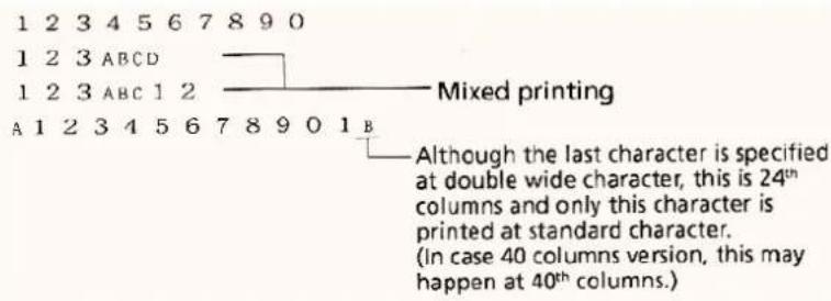
②Double wide character specifying (SO, RS) command By inputting SO (0EH) and RS (1EH) into the nominated columns, the data after this command is printed in double wide character. This is canceled by line feed operation or inputting SI or US command. Although both of standard character and double wide character can exist in one line.
When the total characters goes to 24 (40) columns on the basis of calculation at standard character basis, printer performs automatic printing (buffer full printing)
| S O | 1 2 3 4 5 6 7 8 9 0 | C R | |||||
| S O | 1 2 3 | S I | A B C D | C R | |||
| S O | 1 2 3 | S I | A B C | S O | 12 | C R | |
| A | S O | 1 2 3 4 5 6 7 8 9 0 1 B | |||||
(3) Data cancellation (CAN) command
In inputting of CAN (18H) code, all of the data before CAN code at same one line is canceled.
| SO | 123456 | CAN | ABC | CR |
A B C * "SO" command is not canceled and "123456" is canceled. Therefore, "ABC" are printed at double wide characters.
(4) Inverted character specifying (DC2) command
By inputting data adding DC2 (12H) into the beginning of the line, (in case of adding this command into the position except for the beginning of line, this command is ignored.) all of the data after this command is printed at inverted character.
Cancellation of inverted character is conducted by inputting DC2 again or DC1 (initial setting).
In case inverted character is specified by dip switch setting, all of this operation goes to opposite way.
(5) Initial set (DC1) command
By inputting DC1 (11H), each condition specified after power is ON is canceled and printer goes to initial condition same as the condition right after power is ON.
But, the data in input buffer is not changed.
(6) Continuous line feed specifying (ESC + "B" + n)
By inputting ESC (1BH) + "B" (42H) + n code, printer performs continuous line feeding at n dot lines.
But, n is to be within 4 ≤ n ≤ 255 and must be even number. In case odd number is specified for n, this is to be concerned as even data of "n - 1".
And in case that n is specified at the out of available range, this command is automatically ignored.
When inputting this command, in case there is some data in the input buffer, printer prints the data. But the printed line (10 dots line) is included in the volume of line feed n. Therefore in case n is 4 ≤ n ≤ 9 line spacing may go to "0".
(7) International character specifying command (ESC + "R" + n)
By inputting ESC (1BH) + "R" (52H) + n code, the character after this command is set at the characters table of specified country.
The value of n and setting of each countries
| n Country n Country | |||
| 0 U.S. | A. 5 Sweden | ||
| 1 | France | 6 | Italy |
| 2 | Germany | 7 | Spain |
| 3 U.K. | 8 Japan | ||
| 4 | Denmark | ||
Remarks: In case the value of n is out of the above range, Country is set automatically at U.S.A.
When power is ON, initial setting varies depending on Dip Switch setting.
(8) Registration of sentence command (ESC + "/" + n)
By inputting ESC (1BH) + "/" (2FH) + n 'Registration of sentence' command, the data of 24 (40) bytes following after n is registered.
The data between 1 to 8 is to be specified as the data for n.
In case that the data of n is specified out of this range, the data following after this command is recognized as normal print data, the registration is not conducted and printer prints the data immediately.
In case the registered data already exists at n, previous data is automatically canceled and new data is overwritten.
The total of this data must be below one line and the end of this data must be finished by CR (0DH) or LF (0AH).
In case the data over 24 (40) is registered, although the data below 24 (40) can be registered properly, the data over 24 (40) is printed as normal print data.
ESC command can not be registered.
(9) Printing registered sentence (ESC + "!" + n)
By inputting ESC (1BH) + "!" (21H) + n, printer prints the sentence registered at the value specified by n.
The data between 1 and 8 is to be specified for n. In case the data is registered out of this range, this transaction is not conducted.
Remarks 1) Although the data can be registered at 24 (40) bytes, in case the data goes over 24 (40) columns (for example, in case double width or double width and double height is specified in this registration.) Printer prints the data by 24 (40) columns and the columns over 24 (40) columns is fed to the next line. Make sure to register the characters concerning the actual print results.
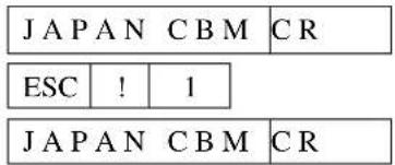
Remarks 2) In case double wide and double high or inverted characters are specified in this registration, as far as this setting is not canceled, printer prints the data following this setting.
Example 1)
| ESC | /1 | This is a pen CR | ...... Sentence is registered to 1. | |||
| ESC | / | 9 | Is This a pen? | CR ...... can not be registered to 9. | ||
| ESC | / | It is a pen | CR | ...... The registered sentence is overwritten on the sentence registered in previous 1. | ||
| ESC | ! | ...... prints the sentence registered in 1. | ||||
| 1 | It is a pen |
| 2 | |
| 3 | |
| 4 | |
| 5 | |
| 6 | |
| 7 | |
| 8 |
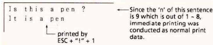
Example 2)

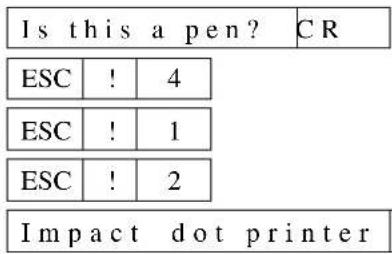
| 1 | This is apen | |||
| 2 | Japan CBM Corporation Mi | |||
| 3 | ||||
| 4 | SO | CITIZEN | SI | NEW PRODUCTS |
| 5 | ||||
| 6 | ||||
| 7 | ||||
| 8 | ||||
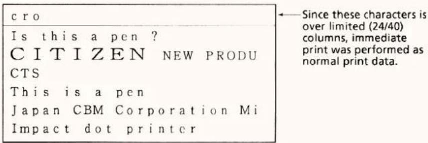
Example 3)

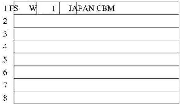
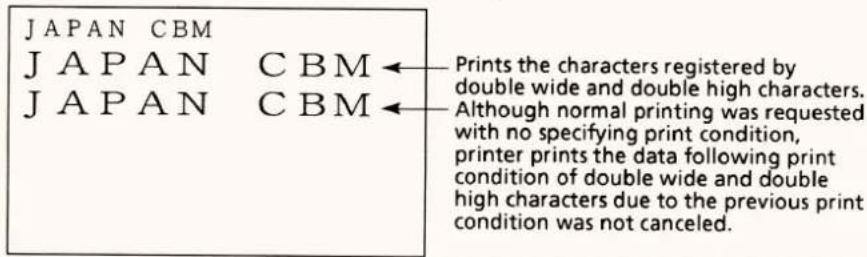
(10) Defining the download character command (ESC + "&")
① In case of 24 columns mode
By inputting ESC (1BH) + "&" (26H) + A1 + A2 code and the pattern data following after this code, nominated pattern can be registered.
Maximum numbers of characters can be registered are 8 characters and this can be registered into the nominated address range between 20H and FFH.
Make sure that in case new data is registered to the address range already has old data, the old data is automatically overwritten and new data is registered.
Furthermore, in case the data over 8 characters is registered, all of the previous data is cleared automatically.
[Specifying address]
The specified address conforms to the character codes and these characters can be accessed as well as the internal characters after registration.
In case any internal characters already exists in the address specified for registered characters, the internal characters are replaced.
A1 means the address of start to be registered and A2 means the address of finish to be registered.
[Data transmission method]
d-1) In case of one character registration The address is to be specified from the 20H \~ FFH, then the specified address is considered as A1. In case of one character registration, the address of start and finish are to be same. Therefore, A1 = A2.
$$ \mathrm{ESC} +" \ & " + \mathrm{A1} + \mathrm{A2} +" \text { Pattern data(6bytes) }" $$
IB 26 41 41 FF·FF·FF·FF·FF·FF
After the above control, in case the character code of 41H is specified, full dot printing of 6 · 8 dot matrix printing is performed. (Character "A" can not be accessed to.)
d-2) In case of multi-characters registration
By conducting one character registration continuously, 8 characters can be registered at maximum. In case multi-characters are registered into continuous address (character codes), in specifying the address to start registration is A1 and the address to finish registration is A2, maximum 8 characters can be registered.
$$ \text { Remarks) } \mathrm{A} 1 < \mathrm{A} 2, \mathrm{A} 2 - \mathrm{A} 1 = < 7 $$
[Configuration of pattern data] In case of 24 columns model
The pattern data to be registered for one character is 6 byte. This means the pattern comprises 6 · 8 dots matrix is decomposed to 6 portions divided to the direction of lengthwise. The data of 6 bytes in total is to be transmitted as each one bytes data.
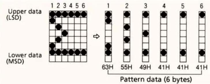
[Print of registered characters]
In case of printing the registered characters, these characters are printed by command (CR, LF, ESC + "B" + n) at same print condition as the other internal characters.
② In case of 40 columns model (ESC + "&" + Cl + A1 + A2)
In inputting ESC (1BH) + "&" + C1 + A1 + A2 and the pattern data following after these codes, nominated pattern can be registered.
The total numbers of characters can be registered are 224 characters and these characters can be registered into the nominated address between the range of 20H \~ FFH.
But in case new pattern is registered into the address has already old pattern, the old data is automatically cleared and new pattern is registered.
[The upper bit use ]
The data is specified in parameter C1 to recognize whether the registered character is using the upper bit or not.
C1 = 0 (00H) : The upper bit is not used.
C1 = other than 0 : The upper bit is used.
Even if the upper bit is used, 0 is specified in this parameter, in case of double width and double height character, the highest dot is missing and proper print result may not be conducted.
[Specifying address]
A1 : Start of the registration address (20H \~ FFH)
A2 : End of the registration address (20H \~ FFH)
[Configuration of pattern data]
The pattern data to be registered for one character is 9 byte.
This means the pattern comprises 9 × 8 dots matrix is decomposed to 9 portions divided to the direction of lengthwise and the data of 9 bytes in total is to be transmitted as each one bytes data.
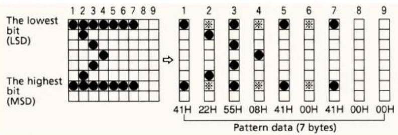
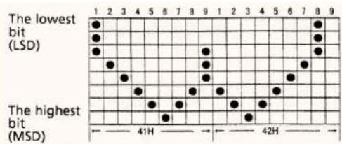
Since this model is using half dot printing method, this printer can not specify the continuous dots to the direction of printing direction. (Horizontal direction) Therefore, the pattern can not be registered in the position of "e" mark, even if the pattern is specified in this position.
By registration of the data of 2 characters, double width as one character can be compromised.
scatter
| Bit Type | Position | Value | |---|---|---| | The lowest bit (LSD) | 1 | ● | | The lowest bit (LSD) | 2 | ● | | The lowest bit (LSD) | 3 | ● | | The lowest bit (LSD) | 4 | ● | | The lowest bit (LSD) | 5 | ● | | The lowest bit (LSD) | 6 | ● | | The lowest bit (LSD) | 7 | ● | | The lowest bit (LSD) | 8 | ● | | The lowest bit (LSD) | 9 | ● | | The highest bit (MSD) | 1 | ● | | The highest bit (MSD) | 2 | ● | | The highest bit (MSD) | 3 | ● | | The highest bit (MSD) | 4 | ● | | The highest bit (MSD) | 5 | ● | | The highest bit (MSD) | 6 | ● | | The highest bit (MSD) | 7 | ● | | The highest bit (MSD) | 8 | ● | | The highest bit (MSD) | 9 | ● | The highest bit (MSD) | 10 | ● | The highest bit (MSD) | 11 | ● | | The highest bit (MSD) | 12 | ● | | The highest bit (MSD) | 13 | ● | | The highest bit (MSD) | 14 | ● | | The highest bit (MSD) | 15 | ● | | The highest bit (MSD) | 16 | ● | | The highest bit (MSD) | 17 | ● | | The highest bit (MSD) | 18 | ● | | The highest bit (MSD) | 19 | ● | | The highest bit (MSD) | 20 | ● | | The highest bit (MSD) | 21 | ● | | The highest bit (MSD) | 22 | ● | | The highest bit (MSD) | 23 | ● | | The highest bit (MSD) | 24 | ● | | The highest bit (MSD) | 25 | ● | | The highest bit (MSD) | 26 | ● | | The highest bit (MSD) | 27 | ● | | The highest bit (MSD) | 28 | ● | | The highest bit (MSD) | 29 | ● | | The highest bit (MSD) | 30 | ● | | The highest bit (MSD) | 31 | ● | | The highest bit (MSD) | 32 | ● | | The highest bit (MSD) | 33 | ● | | The highest bit (MSD) | 34 | ● | | The highest bit (MSD) | 35 | ● | | The highest bit (MSD) | 36 | ● | | The highest bit (MSD) | 37 | ● | | The highest bit (MSD) | 38 | ● | | The highest bit (MSD) | 39 | ● | | The highest bit (MSD) | 40 | ● | | The highest bit (MSD) | 41H | ● | | The highest bit (MSD) | -10H | ● | | The highest bit (MSD) | -11H | ● | | The highest bit (MSD) | -12H | ● | | The highest bit (MSD) | -13H | ● | | The highest bit (MSD) | -14H | ● | | The highest bit (MSD) | -15H | ● | | The highest bit (MSD) | -16H | ● | | The highest bit (MSD) | -17H | ● | | The highest bit (MSD) | -18H | ● | | The highest bit (MSD) | -19H | ● | | The highest bit (MSD) | -20H | ● | | The highest bit (MSD) | -21H | ● | | The highest bit (MSD) | -22H | ● | | The highest bit (MSD) | -23H | ● | | The highest bit (MSD) | -24H | ● | | The highest bit (MSD) | -25H | ● | | The highest bit (MSD) | -26H | ● | | The highest bit (MSD) | -27H | ● | | The highest bit (MSD) | -28H | ● | | The highest bit (MSD) | -29H | ● | | The highest bit (MSD) | -30H | ● | | The highest bit (MSD) | -31H | ● | | The highest bit (MSD) | -32H | ● | | The highest bit (MSD) | -33H | ● | | The highest bit (MSD) | -34H | ● | | The highest bit (MSD) | -35H | ● | | The highest bit (MSD) | -36H | ● | | The highest bit (MSD) | -37H | ● | | The highest bit (MSD) | -38H | ● | | The highest bit (MSD) | -39H | ● | | The highest bit (MSD) | -40H | ● | | The highest bit (MSD) | -41H | ● | | The highest bit (MSD) | -42H | ● | | The highest bit (MSD) | -43H | ● | | The highest bit (MSD) | -44H | ● | | The highest bit (MSD) | -45H | ● | | The highest bit (MSD) | -46H | ● | | The highest bit (MSD) | -47H | ● | | The highest bit (MSD) | -48H | ● | | The highest bit (MSD) | -49H | ● | | The highest bit (MSD) | -50H | ● | | The lowest bit (LSD) [●] [●] [●] [●] [●] [●] [●] [●] [●] [●] [●] [●] [●] [●] [●] [●] [●] [●] [●] [●] [●] [●] [●] [●] [●] [●] [●] [●] [●] [●] [●] [●] [●] [●][●] [●] [●] [●] [●] [●] [●] [●] [●] [●] [●] [●] [●] [●] [●] [●] [●] [●] [●] [●] [●] [●] [●] [●] [●] [●] [●] [●] [●] [●] [●] [●] [●] [○] [○]After following the code of ESC + "&" + 01H (Remarks) + 41H + 42H, by sending the following date,
Date 07H, 08H, 10H, 20H, 40H, 80H, 40H, 20H, 1CH
20H, 40H, 80H, 40H, 20H, 10H, 08H, 07H, 00H
the character of "W" in double width can be registered in the area of 41H and 42h.
[Printing of registered characters]
In case of printing registered characters, command (ESC + "%" + 1) for specifying registered characters is to be conducted initially.
Then, by sending 41H and 42H the word of "W" in double width can be printed.
Remarks) Even though any data was registered in the upper bit, in case "0" is specified for "C1" parameter, the print result may not be same as the image.
(11) Download character valid/invalid command (ESC + "%" + n)
By inputting ESC (1BH) + "%" (26H) + n codes, selection of valid or invalid of registered characters is performed.
N = 1 (01H) : Enable the registered characters.
(In case there is no change in the registration address, internal characters are printed.)
N = 0 (00H) : Disable the registered characters.
Internal characters are print.
Initial setting is for printing internal characters.
Even though any characters were registered by command, in case the above setting is "disable", the registered characters can not be printed.
Remarks ) This command is available only for 40 columns model.
(12) Bit image printing command (ESC + "K" + n1 + n2 + n3)
By inputting ESC(4BH) + "K" + n1 + n2 + n3 code, text mode is changed to bit image mode, n1, n2, n3 specify the volume of bit map data to be transmitted after this command.
Therefore, n1 shows the number of bytes to the direction of side, n2 (lower) and n3 (higher) show the number of dot lines at the direction of lengthwise.
(The relation between data and print result.)
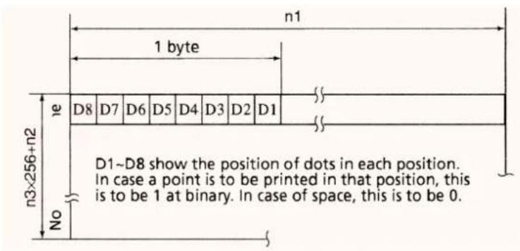
(The available range of parameter specifying)
| model n1 n2 n3 | |||
| 24 columns model 1 | ~18 0~255 0~1 | ||
| 40 columns model 1 | ~23 0~255 0~1 |
Remarks: In case the value is specified out of the above available range or n2 = n3 = 0, bit image mode is canceled and mode is changed to text mode.
This printer prints the data which is not sufficient as a space after Lead -in the data of 4 dots line or after filling the data specified in n1, n2, n3
Remarks 1): In 40 columns, in case n1 = 1 is specifies, 4 dots from lowest columns dots (LSC-DOT) are ignored. This is due to the total number of dot for 1 line is 180.
Remarks 2): Mode is changed to text print mode after printing bit image.
(13) Specifying double wide and double high character command (FS + "W" + 1)
By inputting the code of FS (1CH) + "W" (57H) + (01H), double width and double height is specified.
This command prints the data following after this command as double width and double height.
(14) Cancellation of double wide and double high character command (FS + "W"+0)
By inputting FS (1CH) + "W" (57H) + 0 (00H) code, double width and double height is canceled.
Remarks 1) Although both of standard characters and double wide characters can exist in the same line, in case the total columns go to 24 (40) columns at standard character basis, this printer con-duct buffer full printing automatically.
Remarks 2) In case both of double wide and double high character and double wide character are specified, double width and double height is specified.
Example)
| 1C | W | 1 | 1 2 3 4 5 6 7 8 9 | CR | |||||
| 1C | W | 0 | A | B | C | 1C | W | 1 | 1 2 3 CR |
| 1C | W | 0 | A | 1C | W | 1 | 1 2 3 4 5 6 7 8 9 0 1 B | ||
1 2 3 4 5 6 7 8 9
ABC 1 2 3
A 1 2 3 4 5 6 7 8 9 1 B Even though the last character is
Even though the last character is specified as double width and double height, since this character is 24 ^th column, this character is printed as an standard character. (In case of 40 columns model, this means 40 ^th column.)
9. CHARACTER SET
9.1 Japanese character code table
| Lower Bit\上位 | 0 | 1 | 2 | 3 | 4 | 5 | 6 | 7 | 8 | 9 | A | B | C | D | E | F | |
| 0000 | 0001 | 0010 | 0011 | 0100 | 0101 | 0110 | 0111 | 1000 | 1001 | 1010 | 1011 | 1100 | 1101 | 1110 | 1111 | ||
| 0 | 0000 | NUL | SP | 0 | a | P | p | 一 | ⊥ | € | - | 夕 | ミ | 円 | |||
| 0 | 16 | 32 | 48 | 64 | 80 | 96 | 112 | 128 | 144 | 160 | 176 | 192 | 208 | 224 | 240 | ||
| 1 | 0001 | ! | 1 | A | Q | a | q | 一 | T | ア | チ | ム | 年 | ||||
| 1 | 17 | 33 | 49 | 65 | 81 | 67 | 113 | 129 | 145 | 161 | 177 | 193 | 209 | 225 | 241 | ||
| 2 | 0010 | DC2 | · | 2 | B | R | b | r | 一 | + | r | イ | ツ | メ | 月 | ||
| 2 | 18 | 34 | 50 | 66 | 82 | 68 | 114 | 130 | 146 | 162 | 178 | 194 | 210 | 226 | 242 | ||
| 3 | 0011 | DC3 | # | 3 | C | S | c | s | 一 | ト | j | ウ | テ | モ | 日 | ||
| 3 | 19 | 35 | 51 | 67 | 83 | 99 | 115 | 131 | 147 | 163 | 179 | 195 | 211 | 227 | 243 | ||
| 4 | 0100 | DC4 | $ | 4 | D | T | d | t | 一 | 一 | エ | ト | ヤ | ||||
| 4 | 20 | 36 | 52 | 68 | 84 | 100 | 116 | 132 | 148 | 164 | 180 | 196 | 212 | 228 | 244 | ||
| 5 | 0101 | % | 5 | E | U | e | u | 一 | オ | ナ | ユ | ||||||
| 5 | 21 | 37 | 53 | 69 | 85 | 101 | 117 | 133 | 149 | 165 | 181 | 197 | 213 | 229 | 245 | ||
| 6 | 0110 | & | 6 | F | V | f | v | | | ラ | カ | ニ | ヨ | |||||
| 6 | 22 | 38 | 54 | 70 | 86 | 102 | 118 | 134 | 150 | 166 | 182 | 198 | 214 | 230 | 246 | ||
| 7 | 0111 | · | 7 | G | W | g | w | | | ア | キ | ヌ | ラ | |||||
| 7 | 23 | 39 | 55 | 71 | 87 | 103 | 119 | 135 | 151 | 167 | 183 | 199 | 215 | 231 | 247 | ||
| 8 | 1000 | CAN | ( | 8 | H | X | h | x | r | イ | ク | ネ | リ | ||||
| 8 | 24 | 40 | 56 | 72 | 88 | 104 | 120 | 136 | 152 | 168 | 184 | 200 | 216 | 232 | 248 | ||
| 9 | 1001 | ) | 9 | I | Y | i | y | ` | ウ | ケ | ノ | ル | |||||
| 9 | 25 | 41 | 57 | 73 | 89 | 105 | 121 | 137 | 153 | 169 | 185 | 201 | 217 | 233 | 249 | ||
| A | 1010 | LF | * | : | J | Z | j | z | ` | エ | コ | ハ | レ | ||||
| 10 | 26 | 42 | 58 | 74 | 90 | 106 | 122 | 138 | 154 | 170 | 186 | 202 | 218 | 234 | 250 | ||
| B | 1011 | ESC | + | : | K | { | k | { | ` | オ | サ | ヒ | ロ | ||||
| 11 | 27 | 43 | 59 | 75 | 91 | 107 | 123 | 139 | 155 | 171 | 187 | 203 | 219 | 235 | 251 | ||
| C | 1100 | · | ( | L | ¥ | l | ` | ヤ | シ | フ | ワ | ||||||
| 12 | 28 | 44 | 60 | 76 | 92 | 108 | 124 | 140 | 156 | 172 | 188 | 204 | 220 | 236 | 252 | ||
| D | 1101 | CR | - | = | M | } | m | ユ | ス | ヘ | ン | ||||||
| 13 | 29 | 45 | 61 | 77 | 93 | 109 | 125 | 141 | 157 | 173 | 189 | 205 | 221 | 237 | 253 | ||
| E | 1110 | SO | ) | N | ^ | n | a | セ | ホ | ||||||||
| 14 | 30 | 46 | 62 | 78 | 94 | 110 | 126 | 142 | 158 | 174 | 190 | 206 | 222 | 238 | 254 | ||
| F | 1111 | / | ? | O | - | o | + | ノ | ッ | ソ | マ | ||||||
| 15 | 31 | .7 | 63 | 79 | 95 | 111 | 127 | 143 | 159 | 175 | 191 | 207 | 223 | 239 | 255 |
Remarks: SP means: "Space" (blank).
9.2 International character code table
| UpperLower BRIt | 0 | 1 | 2 | 3 | 4 | 5 | 6 | 7 | 8 | 9 | A | B | C | D | E | F | |
| 0000 | 0001 | 0010 | 0011 | 0100 | 0101 | 0110 | 0111 | 1000 | 1001 | 1010 | 1011 | 1100 | 1101 | 1110 | 1111 | ||
| 0 | 0000 | NUL0 | 16 | SP32 | 048 | 64 | P80 | 96 | p112 | -128 | ⊥144 | €160 | 176 | 192 | 208 | 224 | 240 |
| 1 | 0001 | 1 | 17 | !33 | 149 | A65 | Q81 | a67 | q113 | -129 | T145 | 161 | 177 | 193 | 209 | 225 | 241 |
| 2 | 0010 | 2 | 18 | ·34 | 250 | B66 | R82 | b68 | r114 | -130 | -146 | 162 | 178 | 194 | 210 | 226 | 242 |
| 3 | 0011 | 3 | 19 | #35 | 351 | C67 | S83 | c99 | s115 | -131 | 卜147 | 163 | 179 | 195 | 211 | 227 | 243 |
| 4 | 0100 | 4 | 20 | $36 | 452 | D68 | T84 | d100 | t116 | -132 | -148 | 164 | 180 | 196 | 212 | 228 | 244 |
| 5 | 0101 | 5 | 21 | %37 | 553 | E69 | U85 | e101 | u117 | -133 | -149 | 165 | 181 | 197 | 213 | 229 | 245 |
| 6 | 0110 | 6 | 22 | &38 | 654 | F70 | V86 | f102 | v118 | ■134 | |150 | 166 | 182 | 198 | 214 | 230 | 246 |
| 7 | 0111 | 7 | 23 | ·39 | 755 | G71 | W87 | g103 | w119 | ■135 | |151 | 167 | 183 | 199 | 215 | 231 | 247 |
| 8 | 1000 | 8 | 24 | (40 | 856 | H72 | X88 | h104 | x120 | |136 | r152 | 168 | 184 | 200 | 216 | 232 | 248 |
| 9 | 1001 | 9 | 25 | )41 | 957 | I73 | Y89 | i105 | y121 | |137 | -153 | 169 | 185 | 201 | 217 | 233 | 249 |
| A | 1010 | LF10 | 26 | *42 | :58 | J74 | Z90 | j106 | z122 | |138 | -154 | 170 | 186 | 202 | 218 | 234 | 250 |
| B | 1011 | 11 | ESC27 | +43 | :59 | K75 | (91 | k107 | (123 | |139 | ,155 | 171 | 187 | 203 | 219 | 235 | 251 |
| C | 1100 | 12 | 28 | ·44 | <60 | L76 | \92 | l108 | :124 | |140 | r156 | 172 | 188 | 204 | 220 | 236 | 252 |
| D | 1101 | CR13 | 29 | -45 | =61 | M77 | )93 | m109 | )125 | ■141 | 、157 | 173 | 189 | 205 | 221 | 237 | 253 |
| E | 1110 | SO14 | 30 | ·46 | >62 | N78 | ^94 | n110 | ~126 | ■142 | 、158 | 174 | 190 | 206 | 222 | 238 | 254 |
| F | 1111 | 15 | 31 | /47 | ?63 | O79 | -95 | o111 | ■127 | +143 | /159 | 175 | 191 | 207 | 223 | 239 | 255 |
Remarks: SP means: "Space" (blank).
9.3 Character code table
(The characters of *1\~*12 in the below table can be changed to the characters in the next page.)
| 下位B4\Upper B5 | 0 | 1 | 2 | 3 | 4 | 5 | 6 | 7 | 8 | 9 | A | B | C | D | E | F | |
| 0000 | 0001 | 0010 | 0011 | 0100 | 0101 | 0110 | 0111 | 1000 | 1001 | 1010 | 1011 | 1100 | 1101 | 1110 | 1111 | ||
| 0 | 0000 | NUL | SP | 0 | *3 | P | *8 | p | - | ⊥ | € | ||||||
| 0 | 16 | 32 | 48 | 64 | 80 | 96 | 112 | 128 | 144 | 160 | 176 | 192 | 208 | 224 | 240 | ||
| 1 | 0001 | ! | ! | 1 | A | Q | a | q | - | T | |||||||
| 1 | 17 | 33 | 49 | 65 | 81 | 67 | 113 | 129 | 145 | 161 | 177 | 193 | 209 | 225 | 241 | ||
| 2 | 0010 | DC2 | · | 2 | B | R | b | r | - | - | |||||||
| 2 | 18 | 34 | 50 | 66 | 82 | 68 | 114 | 130 | 146 | 162 | 178 | 194 | 210 | 226 | 242 | ||
| 3 | 0011 | DC3 | *1 | 3 | C | S | c | s | - | - | |||||||
| 3 | 19 | 35 | 51 | 67 | 83 | 99 | 115 | 131 | 147 | 163 | 179 | 195 | 211 | 227 | 243 | ||
| 4 | 0100 | DC4 | *2 | 4 | D | T | d | t | - | - | |||||||
| 4 | 20 | 36 | 52 | 68 | 84 | 100 | 116 | 132 | 148 | 164 | 180 | 196 | 212 | 228 | 244 | ||
| 5 | 0101 | % | 5 | E | U | e | u | - | - | ||||||||
| 5 | 21 | 37 | 53 | 69 | 85 | 101 | 117 | 133 | 149 | 165 | 181 | 197 | 213 | 229 | 245 | ||
| 6 | 0110 | & | 6 | F | V | f | v | | | |||||||||
| 6 | 22 | 38 | 54 | 70 | 86 | 102 | 118 | 134 | 150 | 166 | 182 | 198 | 214 | 230 | 246 | ||
| 7 | 0111 | · | 7 | G | W | g | w | | | |||||||||
| 7 | 23 | 39 | 65 | 71 | 87 | 103 | 119 | 135 | 151 | 167 | 183 | 199 | 215 | 231 | 247 | ||
| 8 | 1000 | CAN | ( | 8 | H | X | h | x | r | ||||||||
| 8 | 24 | 40 | 56 | 72 | 88 | 104 | 120 | 136 | 152 | 168 | 184 | 200 | 218 | 232 | 248 | ||
| 9 | 1001 | ) | 9 | I | Y | i | y | ||||||||||
| 9 | 25 | 41 | 57 | 73 | 89 | 105 | 121 | 137 | 153 | 169 | 185 | 201 | 217 | 233 | 249 | ||
| A | 1010 | LF | * | : | J | Z | j | z | |||||||||
| 10 | 26 | 42 | 58 | 74 | 90 | 106 | 122 | 138 | 154 | 170 | 186 | 202 | 218 | 234 | 250 | ||
| B | 1011 | ESC | + | : | K | *4 | k | *9 | J | ||||||||
| 11 | 27 | 43 | 59 | 75 | 91 | 107 | 123 | 139 | 155 | 171 | 187 | 203 | 219 | 235 | 251 | ||
| C | 1100 | < | L | *5 | l | *10 | |||||||||||
| 12 | 28 | 44 | 60 | 76 | 92 | 108 | 124 | 140 | 156 | 172 | 188 | 204 | 220 | 236 | 252 | ||
| D | 1101 | CR | - | = | M | *6 | m | *11 | |||||||||
| 13 | 29 | 45 | 61 | 77 | 93 | 109 | 125 | 141 | 157 | 173 | 189 | 205 | 221 | 237 | 253 | ||
| E | 1110 | SO | > | N | *7 | n | *12 | ||||||||||
| 14 | 30 | 46 | 62 | 78 | 94 | 110 | 126 | 142 | 158 | 174 | 190 | 206 | 222 | 238 | 254 | ||
| F | 1111 | / | ? | O | o | + | |||||||||||
| 15 | 31 | 47 | 63 | 79 | 95 | 111 | 127 | 143 | 159 | 175 | 191 | 207 | 223 | 239 | 255 |
Remarks: SP means: "Space" (blank).
| Country Code | U.S.A. | France | Germany | U.K. | Denmark | Sweden | Italy | Spain | |
| *1 | 23H | # | # | # | £ | # | # | # | Pt |
| *2 | 24H | †† | $ | ||||||
| *3 | 40H | @ | A | § | @ | @ | Ê | # | @ |
| *4 | 5BH | [ | * | Â | [ | Æ | Â | * | i |
| *5 | 5CH | \ | C | O | \ | ∅ | Ö | \ | N |
| *6 | 5DH | ] | § | Ü | ] | À | À | # | ↓ |
| *7 | 5EH | ^ | ^ | ^ | ^ | ^ | Ü | ^ | ^ |
| *8 | 60H | · | · | · | · | · | # | ü | · |
| *9 | 7BH | [ | # | # | ( | æ | # | # | .. |
| *10 | 7CH | | | # | # | | | # | ü | ü | ü |
| *11 | 7DH | ) | # | ü | ) | ä | ä | ä | ] |
| *12 | 7EH | ~ | .. | # | ~ | ~ | ü | ì | ~ |
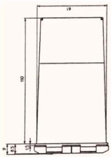
10. OUTLINE DRAWING
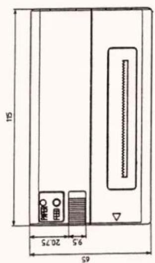
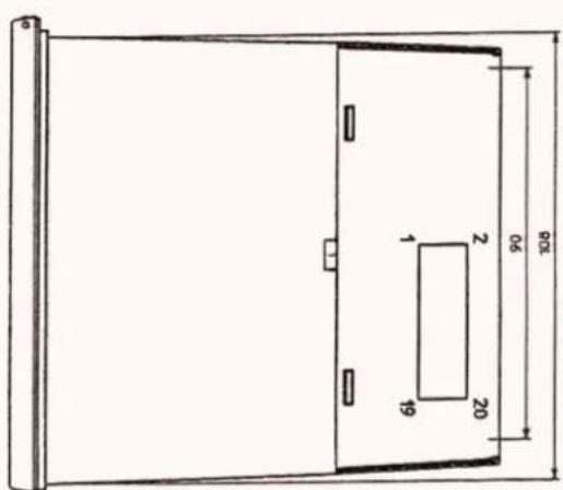
- Declaration of Conformity
- IMPORTANT SAFETY INSTRUCTIONS
- Sicherheitshinweis
- CAUTIONS FOR SAFE USE (Be sure to follow these cautions)
- WARNING!
- CAUTION
- PRECAUTIONS FOR INSTALLATION
- CAUTION FOR HANDLING
- Do not carry out the following operation, since they may be cause of breakage.
- To avoid injury and prevent damage from spreading.
- ORDINARY MAINTENANCE
- CONTENTS
- OUTLINE....8
- GENERAL SPECIFICATIONS....9
- OUTER APPEARANCE AND EXPLANATION OF EACH PART....11
- OPERATION....13
- PARALLEL INTERFACE....22
- SERIAL INTERFACE....26
- DIP SWITCH SETTING....31
- PRINT CONTROL FUNCTION....32
- CHARACTER SET 48
- OUTLINE DRAWING....52
- OUTLINE
- Features
- Accessories
- GENERAL SPECIFICATIONS
- Model classifications
- Power Supply
- Cautions for Roll Paper
- OUTER APPEARANCE AND EXPLANATION OF EACH PART
- Outer Appearance and Explanation of Each Part
- Explanation of Each Part
- OPERATION
- Rack Mounting
- Power Supply Connection
- Panel Opening/Closing
- Opening/Closing of Front Panel
- Opening/Closing of Ribbon Cover
- Paper Feeding
- Setting Ribbon Cassette
- REMARK
- Setting Printing Paper
- Self-Printing Function
- Example of printing at dump mode. (40 columns model)
- Paper Near End Sensor, Paper End Sensor, and Mechanical Alarm
- Paper Near End
- Paper End
- Mechanical Alarm
- Auto Loading Function
- PARALLEL INTERFACE
- Specifications
- Connector Pin's Configuration
- Explanation of Input/Output Signals
- 1) Input Signals into Printer
- 2) Output Signals from Printer
- Electrical Characteristics
- SERIAL INTERFACE
- Specifications
- Connector Connection Diagram
- Explanation of Input/Output Signals
- Electrical Characteristics
- Error Detection
- DIP SWITCH SETTING
- PRINT CONTROL FUNCTION
- Control code list
- Input data format
- Line feed command after printing (CR, LF)
- Example 1)
- CHARACTER SET
- Japanese character code table
- International character code table
- Character code table
- OUTLINE DRAWING
Brand : CITIZEN
Model : CBM-920
Category : Printer