
RDX QuikStation 4 - Disk array Tandberg Data - Free user manual and instructions
Find the device manual for free RDX QuikStation 4 Tandberg Data in PDF.


| Product Type | Disk Array (RDX Docking Station) |
| Brand | Tandberg Data |
| Model | RDX QuikStation 4 |
| Form Factor | Desktop |
| Number of Bays | 4 |
| Supported Media | RDX Removable Disk Cartridges (up to 5TB each) |
| Host Interface | USB 3.0, eSATA |
| Data Transfer Rate | Up to 5 Gbps (USB 3.0) |
| Dimensions (W x H x D) | 440 x 88 x 480 mm |
| Weight | 4.5 kg |
| Power Supply | External AC adapter, 100-240V, 50-60Hz |
| LED Indicators | Power, Activity, Status per bay |
| Hot-Swap Support | Yes, for RDX cartridges |
| Included Software | Backup and recovery software (e.g., Acronis True Image) |
| Operating System Compatibility | Windows, macOS, Linux |
| Cooling | Fan, rear exhaust |
| Maintenance | Clean with dry cloth; keep vents unobstructed |
| Safety | Avoid liquids; use only supplied power adapter |
| Spare Parts | RDX cartridges, power adapter, cables |
| User Serviceable | Cartridges and power adapter only |
| Warranty | 2 years limited |
Frequently Asked Questions - RDX QuikStation 4 Tandberg Data
User questions about RDX QuikStation 4 Tandberg Data
0 question about this device. Answer the ones you know or ask your own.
Ask a new question about this device
Download the instructions for your Disk array in PDF format for free! Find your manual RDX QuikStation 4 - Tandberg Data and take your electronic device back in hand. On this page are published all the documents necessary for the use of your device. RDX QuikStation 4 by Tandberg Data.
USER MANUAL RDX QuikStation 4 Tandberg Data
For QuikStation® 4 and QuikStation 8 Appliances

natural_image
Front view of a black rack-mounted server with multiple drive units and a central processor (no visible text or symbols on the equipment)©2017 Overland Storage, Inc. All rights reserved.
Overland ^® , Overland Storage ^® , ARCvault ^® , DynamicRAID ^® , GuardianOS ^® , NEO ^® , NEO Series ^® , PowerLoader ^® , Protection OS ^® , RAINcloud ^® , REO ^® , REO 4000 ^® , REO Series ^® , Snap Appliance ^® , Snap Care ^® (EU only), SnapSAN ^® , SnapScale ^® , SnapScale X2 ^® , SnapServer ^® , StorAssure ^® , Ultamus ^® , VR2 ^® , and XchangeNOW ^® are registered trademarks of Overland Storage, Inc.
Tandberg Data ^® , AccuGuard ^® , AccuVault ^® , DPS1000 Series ^® , DPS1100 ^® , DPS1200 ^® , DPS2000 ^® , Magnum ^® , QuikStation ^® , QuikStor ^® , RDX ^® , RDXPRO ^® , StorageLibrary ^® , StorageLoader ^® , Tandberg SecureService ^® , Tandberg StorageLibrary ^® , and VXA ^® are registered trademarks of Tandberg Data, Inc.
Desktop Cloud Orchestrator ^® and V3 ^® are registered trademarks of Sphere 3D Corp.
Campus Cluster™, NEO Agility™, RapidRebuild™, Snap ECR™, Snap Encrypted Continuous Replication™, SnapExpansion XSR™, SnapScale X4™, SnapServer DX Series™, SnapServer XSD Series™, SnapServer XSD10™, SnapServer XSR Series™, SnapServer XSR10™, SnapServer XSR120™, SnapServer Manager™, SnapStorage Manager™, and SnapSync™ are trademarks of Overland Storage, Inc.
BizNAS™, QuadPak™, and RDX+™ are trademarks of Tandberg Data, Inc.
G-Series™, Glassware 2.0™, and SnapCLOUD™ are trademarks of Sphere 3D Corp.
All other brand names or trademarks are the property of their respective owners.
The names of companies and individuals used in examples are fictitious and intended to illustrate the use of the software. Any resemblance to actual companies or individuals, whether past or present, is coincidental.
PROPRIETARY NOTICE
All information contained in or disclosed by this document is considered proprietary by Sphere 3D Corp. By accepting this material the recipient agrees that this material and the information contained therein are held in confidence and in trust and will not be used, reproduced in whole or in part, nor its contents revealed to others, except to meet the purpose for which it was delivered. It is understood that no right is conveyed to reproduce or have reproduced any item herein disclosed without express permission from Sphere 3D Corp.
Sphere 3D Corp. provides this manual as is, without warranty of any kind, either expressed or implied, including, but not limited to, the implied warranties of merchantability and fitness for a particular purpose. Sphere 3D Corp. may make improvements or changes in the product(s) or programs described in this manual at any time. These changes will be incorporated in new editions of this publication.
Sphere 3D Corp. assumes no responsibility for the accuracy, completeness, sufficiency, or usefulness of this manual, nor for any problem that might arise from the use of the information in this manual.
FW 01.003.05
REVISION HISTORY
Revision Date Description
A June 2016 Initial release
B June 2017 Minor fixes and updates
C December 2017 Minor fixes including static IP configuration
Sphere 3D Corp.
9112 Spectrum Center Boulevard
San Diego, CA 92123 USA
TEL 1.800.729.8725
1.858.571.5555
FAX 1.858.571.3664
www.sphere3d.com
Preface
Audience and Purpose
This guide describes how to install and operate an RDX QuikStation appliance and is intended for use by anyone deploying the RDX QuikStation 4 or the RDX QuikStation 8 into their network environment. Familiarity with system and network configuration is highly recommended.
The information in this guide applies to both the RDX QuikStation 4 and the RDX QuikStation 8. When there is a significant operational difference, then either the RDX QuikStation 4 or RDX QuikStation 8 is specified.
Organization
The following chapters are included in this guide:
Overview
- Chapter 1, “Product Overview,” provides an overview of the features and components of the RDX QuikStation.
Installation and Setup
- Chapter 2, "Initial Setup and Configuration," describes information on how to rackmount, connect, and initially configure the RDX QuikStation.
- Chapter 3, “iSCSI Configuration,” describes how to connect host computers to RDX QuikStation iSCSI targets, including how to set up iSCSI security.
Using the RDX Remote Management Console
- Chapter 4, “System Configuration,” describes RDX QuikStation system configuration tasks, such as network configuration and user account management.
- Chapter 5, “Logical Device Management,” provides information about the logical device interface in the Remote Management Console.
- Chapter 6, "Manage Tape Library Configurations," shows how to do additional configuration tasks from the Logical Device interface.
- Chapter 7, “Physical Device Management,” provides information about the physical device interface in the Remote Management Console, including ejecting RDX media and reformatting and cloning data.
- Chapter 8, “System Maintenance,” describes RDX QuikStation system maintenance tasks, such as importing and exporting configuration files and updating firmware.
Supplemental Information
- Appendix A, "Troubleshooting," provides basic troubleshooting information.
- Appendix B, "Specifications," provides product specifications.
- Appendix C, "Safety Guidelines," describes important safety precautions to observe when using the RDX QuikStation.
Product Documentation & Software Updates
Product documentation and additional information are available online. Point your browser to:
https://community.sphere3d.com/community/documentation/rdx
For additional information about the RDX QuikStation, refer to the following publications:
- RDX QuikStation 4 Quick Start Guide, part number 1021807.
- RDX QuikStation 8 Quick Start Guide, part number 1021778.
- RDX QuikStation Knowledge Base articles available online.
Technical Support
For help configuring and using your RDX appliance, email our technical support staff at:
US_tandbergsupport@overlandstorage.com
For additional assistance, search at http://www.tandbergdata.com/us/index.cfm/support/.
Conventions
This document exercises several alerts and typographical conventions.
| Convention Description & Usage | |
| WARNING | A Warning contains information concerning personal safety. Failure to follow directions in the Warning could result in bodily harm or death. |
| WARNUNG | Eine Warnung enthält Informationen zur persönlichen Sicherheit. Das Nichtbeachten der Anweisungen in der Warnung kann zu Verletzungen oder zum Tod führen. |
| ADVERTISSEMENT | Un avertissement contient des informations relatives à la sécurité personnelle. Ignorer les instructions dans l'avertissement peut entraîner des lésions corporelles ou la mort. |
| CAUTION | A Caution contains information that the user needs to know to avoid damaging or permanently deleting data or causing physical damage to the hardware or system. |
| IMPORTANT | An Important note is a type of note that provides information essential to the completion of a task or that can impact the product and its function. |
| Item_name | Words in this special boldface font indicate the names of buttons or pages found in the Web Management Interface. |
| Ctrl-Alt-r This type of format details the keys you press simultaneously. In this example, hold down the Ctrl and Alt keys and press the r key. | |
| NOTE A Note indicates neutral or positive information that emphasizes or supplements important points of the main text. A note supplies information that may apply only in special cases, for example, memory limitations or details that apply to specific program versions. | |
| Menu Flow Indicator (>) | Words with a greater than sign between them indicate the flow of actions to accomplish a task.For example, Setup >User >Password indicates that you should click the Setup tab, then the User secondary tab, and finally the Password button to accomplish a task. |
| Courier Italic | A variable for which you must substitute a value. |
| Courier Bold | Commands you enter in a command-line interface (CLI). |
Information contained in this guide has been reviewed for accuracy, but not for product warranty because of the various environments, operating systems, or settings involved. Information and specifications may change without notice.
Contents
Preface
Organization 3
Overview 3
Installation and Setup 3
Using the RDX Remote Management Console 3
Supplemental Information 4
Conventions 4
Chapter 1: Product Overview
RDX QuikStation Features 11
Configuration Flexibility 11
Tandberg Data RDX Removable Disk Technology 11
High Performance and Capacity 11
Compatible with Major Backup Software 12
Integrated Web-based Management 12
Multi-Gigabit Ethernet 12
Compact Design 12
RDX QuikStation 4 Components 12
Front Components 12
Rear Components 13
RDX QuikStation 8 Components 14
Front Components 14
Rear Components 16
Chapter 2: Initial Setup and Configuration
Obtain the IP Address 17
Assign a Static IP Address 18
Automatically Assigning a DHCP IP Address 18
Connect to Remote Management Console 18
Configuring the RDX QuikStation 19
Setting the Language 19
Logical Device Type 20
System Settings 20
Chapter 3: iSCSI Configuration
iSCSI Configuration Overview 22
Connecting to iSCSI Targets Without Authentication 23
Connecting iSCSI Targets for Windows 23
Connecting iSCSI Targets for Linux 26
Connecting iSCSI Targets for Mac OS X 27
Set iSCSI Security 30
Setting iSCSI Security in the Remote Management Console 31
Connecting iSCSI Targets with CHAP for Windows 33
Connecting iSCSI Targets with CHAP for Linux 34
Connecting iSCSI Targets with CHAP for Mac OS X 35
Chapter 4: System Configuration
System Settings Overview 38
Date and Time Configuration 39
Network Configuration 40
Port Configuration Options 44
Notification Configuration 45
Setting Basic Email Notification 46
Setting SMTP Authentication 46
Customizing Email Subject and From Address 47
User Management 47
Group Permissions Overview 47
Adding Users to a Group 48
Removing Users from a Group 49
Editing User Information 49
Recovering the Built-In Administrator Password 50
Convert Device Type 54
Options for RDX QuikStation 55
Setting Removable Disk Options 56
Setting the Auto-Insert Option 57
Chapter 5: Logical Device Management
Logical Device Type Overview 60
Select the Logical Device Type 61
RDX Targets 62
RDX Individual Dock Drives 62
RDX Logical Volume 63
Logical Volumes 65
Creating a Logical Volume 65
Importing a Logical Volume 66
Expanding a Logical Volume 67
Erasing a Logical Volume 68
Exporting the Logical Volume 69
Protected Volumes 70
RDX Protected Volume 70
Creating a Protected Volume 72
Importing a Protected Volume 73
Expanding a Protected Volume 74
Expanding a Fixed Logical Volume File System for a Window Host 75
Expanding a Removable Logical Volume File for a Windows Host 77
Erasing a Protected Volume 78
Exporting the Protected Volume 78
Recovering a Degraded Protected Volume 79
Disk Autoloader 81
View Logical Properties for Autoloaders 82
View Active iSCSI Connections Autoloaders 82
Move a Media Cartridge 82
Set the Autoloader Option 83
Chapter 6: Manage Tape Library Configurations
View Logical Properties for Tape Libraries 84
View Active iSCSI Connections for Tape Libraries 86
Move a Media Cartridge 86
Set the Unique Inquiry Option 87
iSCSI Device General Information 88
Customize the iSCSI Devices View 90
View Active iSCSI Connections for iSCSI Devices 90
Chapter 7: Physical Device Management
Viewing Physical Device Properties 92
Ejecting RDX Media 93
Reformatting RDX Media 94
Cloning Data 94
Chapter 8: System Maintenance
System Maintenance Overview 97
Generate System Logs 98
Diagnostics Tab Options 98
RDX QuikStation Restart and Shutdown 99
System Restart 100
System Shutdown 100
Export RDX QuikStation System Configuration Files 100
Import RDX QuikStation System Configuration Files 101
Manually Update RDX QuikStation Firmware 102
Use a USB Flash Drive for System Tasks 103
Appendix A: Troubleshooting
Basic Troubleshooting Information 105
Appendix B: Specifications
Physical Specifications 107
QuikStation 4 Desktop Appliance ....107
QuikStation 4 Rack-mount Appliance ....108
QuikStation 8 Rack-mount Appliance ....108
Power Specifications 109
Environmental Specifications 109
Safety and Regulatory Agency Compliance 109
European Community 110
Waste of Electronic and Electrical Equipment (WEEE) 110
Australia and New Zealand 110
China RoHS 110
Japan 111
Korea 111
United States: FCC Declaration of Conformity 111
Appendix C: Safety Guidelines
General Safety Precautions 112
Electrical Safety Precautions 112
ESD Precautions 113
Index
1
Product Overview
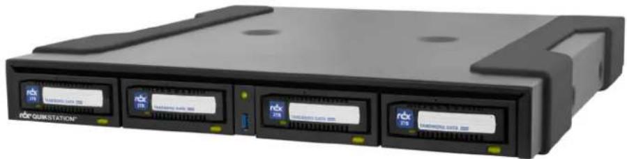
The RDX QuikStation 4 and RDX QuikStation 8 are multi-drive, network-attached, removable-disk arrays built on RDX technology. They combine the removability, durability, and economy of tape with the random accessibility and performance of disk.
Both the RDX QuikStation 4 and QuikStation 8 can be used with different RDX media sizes and configurations resulting in the storage capacity being adapted to match online storage needs with unlimited offline capacity. The RDX QuikStation 4 can offer as much as 16 terabytes of online capacity when used with 4TB RDX media, while the QuikStation 8 can offer as much as 32 terabytes of online capacity when used with 4TB RDX media.
This chapter provides an overview of the RDX QuikStation's features and components.
QuikStation 4 Rack Mount

natural_image
Front view of a rack-mounted server unit with multiple drive bays and indicator lights (no visible text or symbols on the device body)QuikStation 4 Desktop
natural_image
Exterior view of a black rack-mounted electronic device with multiple drive units (no visible text or symbols)QuikStation 8 Rack Mount

Topics in Product Overview:
- RDX QuikStation Features
• RDX QuikStation 4 Components
• RDX QuikStation 8 Components
RDX QuikStation Features
This section provides an overview of the RDX QuikStation's features.
Configuration Flexibility
You can configure the RDX QuikStation as individual Tandberg Data RDX drives with removable iSCSI disk targets or as RDX logical volumes that combine the capacity of the RDX media available.
RDX QuikStation 4
You can configure the RDX QuikStation 4 as four Tandberg Data RDX drives with four removable iSCSI disk targets or a single RDX logical volume combining the capacity of up to four RDX media. The logical volume can be protected against the loss of a disk.
You can also configure the RDX QuikStation 4 as a disk autoloader which can automatically load the next disk when one is ejected.
RDX QuikStation 8
You can configure the RDX QuikStation 8 as eight Tandberg Data RDX drives with eight removable iSCSI disk targets or two RDX logical volumes combining the capacity of up to four RDX media. The logical volumes can be protected against the loss of a disk.
It is also possible to create a protected logical volume of all eight disks which can continue to operate with the loss of two drives.
The RDX QuikStation 8 can be configured as a virtual tape library. You can also configure the RDX QuikStation 8 as a disk autoloader which can automatically load the next disk when one is ejected.
Tandberg Data RDX Removable Disk Technology
RDX data cartridges combine the removability and durability of tape with the random access and performance of disk. RDX cartridges have up to a 30-year media shelf life, and a shock-proof and static-proof cartridge design that makes them ideal for data archiving.
High Performance and Capacity
When configured as a virtual Tandberg Data StorageLibrary T24, the RDX QuikStation can simultaneously read and write from all RDX docks.
RDX QuikStation 4
- When configured as four removable disks, the RDX QuikStation 4 can simultaneously read and write media from all four RDX docks.
- With all four docks using 4TB RDX media, the RDX QuikStation 4 has an online capacity of 16 terabytes and unlimited offline storage capacity.
RDX QuikStation 8
- When configured as eight removable disks, the RDX QuikStation 8 can simultaneously read and write media from all eight RDX docks. Faster speeds may be obtained if the optional 10Gb Ethernet card is installed.
- With all eight docks using 4TB RDX media, the RDX QuikStation 8 has an online capacity of 32 terabytes and unlimited offline storage capacity.
Compatible with Major Backup Software
The RDX QuikStation is compatible with major backup software applications. For a complete list of backup software applications that are compatible with the RDX QuikStation, visit the Tandberg Data website (www.tandbergdata.com), or contact your backup software vendor.
Integrated Web-based Management
The RDX QuikStation Remote Management Console allows you to use a standard web browser from any location to manage, control, diagnose, and configure security for the RDX QuikStation.
Multi-Gigabit Ethernet
The RDX QuikStation 4 has two Gigabit Ethernet ports to provide failover protection and high availability network connectivity. The RDX QuikStation 8 has four Gigabit Ethernet ports and an optional 10Gb port. You can configure the Gigabit Ethernet ports for either bonded or split setup, depending on your needs (see “Port Configuration Options” on page 44).
Compact Design
The RDX QuikStation 4 uses only one unit (1U) of rack space and is also available as a desktop unit, while the RDX QuikStation 8 only uses two units (2U) of rack space, minimizing the impact on data center space requirements.
RDX QuikStation 4 Components
This section describes the RDX QuikStation 4's front panel and back panel components.
Front Components

1 RDX dock (four each)
2 Emergency-eject keyhole (centered above each dock)
NOTE: To use the emergency-eject function, use the Eject Key (included with the RDX QuikStation) and insert it into the keyhole. You can also straighten a paper clip and insert it into the keyhole. The paper clip needs to be sturdy enough to engage the eject function.
| # Description |
| 3 RDX media-eject button/Status LED (four each). |
| 4 USB 3.0 port used for configuration and diagnostics |
| 5 Power button with LED (green when power is ON) |
RDX Media-Eject Button/Status LED
The following table describes Eject Button Status LED functionality.
| LED Status |
| Off (no color) The dock does not have power. |
| Green Power is ON and the dock is working properly. |
| Blinking Green The RDX dock is ejecting media. |
| Amber A fault condition exists with the dock. |
| Blinking Amber A host computer is accessing the media. Media eject is prevented by software. |
Rear Components

| # | Description |
| 1 | AC power connector |
| 2 | Power switch |
| 3 | USB 3.0 ports (2) |
| 4 | VGA/Display port |
| 5 | USB 2.0 ports (6) |
| 6 | Ethernet Ports (2) |
RDX QuikStation 8 Components
This section describes the RDX QuikStation's front panel and back panel components.
Front Components

natural_image
Front view of a server rack unit with labeled ports (1–5) and a central drive, showing no readable text or symbols beyond component labels.# Description
1 RDX dock (eight each)
2 Emergency-eject keyhole (centered above each dock)
NOTE: To use the emergency-eject function, use the Eject Key (included with the RDX QuikStation) and insert it into the keyhole. You can also straighten a paper clip and insert it into the keyhole. The paper clip needs to be sturdy enough to engage the eject function.
3 RDX media-eject button/Status LED (eight each)
4 USB 2.0 port used for configuration and diagnostics
5 Power button
RDX Dock Media-Eject button Status LED
The following table describes Eject Button Status LED functionality.
LED Status
Off (no color) The dock does not have power.
Green Power is ON and the dock is working properly.
Blinking Green The RDX dock is ejecting media.
Amber A fault condition exists with the dock.
Blinking Amber A host computer is accessing the media. Media eject is prevented by software.
QuikStation 8 Front Panel LED
The following table describes the power LED icons.
| LED Usage Appearance Description | |
10Gb connected Software polls 10Gb interface for activity. If there is activity, the LED is refreshed.If there is no activity, the LED is not refreshed.Hardware will turn on the LED when refreshed. Hardware will turn off the LED if not refreshed. If there is activity, the LED is refreshed.If there is no activity, the LED is not refreshed.Hardware will turn on the LED when refreshed. Hardware will turn off the LED if not refreshed. | |
1Gb connected Software polls 1Gb interface for activity. If there is activity, the LED is refreshed.If there is no activity, the LED is not refreshed.Hardware will turn on the LED when refreshed. Hardware will turn off the LED if not refreshed. If there is activity, the LED is refreshed.If there is no activity, the LED is not refreshed.Hardware will turn on the LED when refreshed. Hardware will turn off the LED if not refreshed. | |
| Warning Turned on when there is an error or warning condition that requires the user to check the GUI. | |
| USB in use On or blinking when the front panel USB ports is in use for reading action files or writing status files. | |
 CAUTION: To prevent the loss of data, do not remove the USB media when it is active. Only remove the USB media when the LED is off, indicating all activity is complete. CAUTION: To prevent the loss of data, do not remove the USB media when it is active. Only remove the USB media when the LED is off, indicating all activity is complete. | |
Rear Components
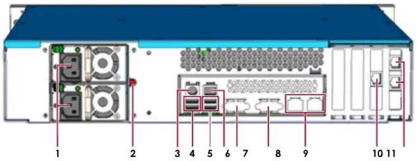
# Description
1 Power connectors (optional 2nd power supply shown)
2 Power Supply reset
3 Mouse/keyboard connector (green/purple)
4 USB 2.0 ports (2)
5 USB 3.0 ports (2)
6 Ethernet port - nonfunctional
7 Serial connector
8 VGA connector
9 Gigabit Ethernet Port (2)
10 10Gigabit Ethernet Port (optional)
11 Gigabit Ethernet Port (2)
2
Initial Setup and Configuration
This section covers the initial setup and configuration of a RDX QuikStation 4 or RDX QuikStation 8.
NOTE: For information concerning the installation and wiring of your RDX QuikStation hardware, either desktop or rack-mount appliance, refer to either the RDX QuikStation 4 Quick Start Guide or the RDX QuikStation 8 Quick Start Guide.
Topics in Setup and Configuration:
- Obtain the IP Address
- Connect to Remote Management Console Configuring the RDX QuikStation
Obtain the IP Address
Once the appliance is installed, either on the desktop or rack, and the cables are attached, an IP address is needed to continue the configuration.
The default network configuration is set for dynamic IP addresses (DHCP), but static IP addresses are also supported. To determine an IP address:
- Attach a monitor to the VGA/display port.
- Power on the unit by pressing the power button.
After the unit initializes, the IP addresses are displayed.
The IP address may also be obtained using a USB stick with a single MBR partition formatted with either FAT32 or NTFS:
- Create an empty network.info file on a USB stick.
- Insert the stick in the USB port on the front of the unit and wait at least 30 seconds for the network configuration to download to the network.info file.
- Move the USB stick to a host computer and scan the updated network.info file to determine the available IP addresses.
Assign a Static IP Address
If DHCP support is not enabled, set a static IP address for the unit:
- Create a network.conf file on a USB stick that contains the following entries:
BOND0_IP4_CONFIG=static
BOND0_IP4_ADDR=nnn.nnn.nnn.nnn
BOND0_IP4_GW=nnn.nnn.nnn.nnn
BOND0_IP4_PREFIX=nn
Insert your IP address, gateway, and prefix. For example:
BOND0_IP4_CONFIG=static
BOND0_IP4_ADDR=192.168.10.111
BOND0_IP4_GW=192.168.10.1
BOND0_IP4_PREFIX=24
- Insert the stick in the USB port on the front of the unit and wait at least two minutes for the network.conf file to update.
The Remote Management Console should now be available at the static IP address selected. For more information on how to configure IP addresses, refer to “Network Configuration” on page 40.
Automatically Assigning a DHCP IP Address
To revert to the default DHCP setting and automatically assign an IP address for the unit:
- Create a network.conf file on a USB stick that contains only the following entry for the IPv4 address.
BOND0_IP4_CONFIG=dhcp
NOTE: No other parameters should be present in this case. The file content is case sensitive. Start the text from the first column and make sure there is no white space around the equal sign (=).
- Insert the USB stick in the USB port on the front of the unit and wait at least one minute for the network.conf file to update.
- Remove the USB stick from the front port.
The unit will restart with the updated DHCP network settings.
Connect to Remote Management Console
Use a web browser to connect to the RDX QuikStation Remote Management Console from any computer on the same network as the RDX QuikStation. Supported operating systems include Microsoft Windows, Linux, and Apple MacOS.
To connect to the Remote Management Console:
- Obtain the unit's IP address.
See "Obtain the IP Address" on page 17.
- From a network host, type the RDX QuikStation IP address in a web browser.
Use the format http://
- Sign in to the Remote Management Console. The default user name/password (Admin/Admin!).
NOTE: Passwords are case-sensitive.
Configuring the RDX QuikStation
You need to configure your RDX QuikStation with a few basic settings to prepare it for use.
Setting the Language
The language used by the Remote Management Console can be changed by any user at any time from any page. Administrative permissions are not required.
To change the language:
- From any Remote Management Console window, click the language drop-down menu at the bottom of the active window. In the example below, the login box is shown.

- At the menu of languages available, select the desired language.
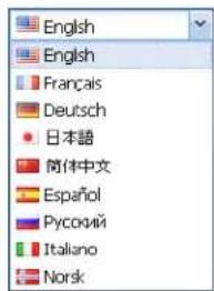
The menu closes and the dialog window appears in the selected language.

All subsequent pages will appear in the selected language.

You can configure your RDX QuikStation as multiple RDX drives (four or eight) or one RDX Logical Volume. The unit is shipped in the multiple RDX drive configuration.
For more information about best use for each logical device type, see “Select the Logical Device Type” on page 61.
System Settings
Refer to the table below for the recommended RDX QuikStation system settings. For more information, see "System Settings Overview" on page 38.
| Setting Purpose Where to find | ||
| Date/Time Set the date and time to your time zone to receive accurate system and troubleshooting information. To avoid time drift, provide the NTP server address. | From the main menu bar in the Remote Management Console, go to System Settings > Date/Time.See “Date and Time Configuration” on page 39 for more information. | |
| Network Information Tandberg Data recommends that you assign a static IP address to prevent inadvertent IP address changes of the iSCSI target. You can also configure optional DNS server addressing information. | From the main menu bar in the Remote Management Console, go to System Settings > Network. The RDX QuikStation automatically reboots after you have made your network changes.See “Network Configuration” on page 40 for more information. | |
| Email Notification A valid email address is needed for logging, error reporting, and password recovery. | From the main menu bar in the Remote Management Console, go to System Settings > Notification.See “Notification Configuration” on page 45 for more information. | |
| User Management As a best practice, change the built-in administrator account password. | From the main menu bar in the Remote Management Console, go to System Settings > User.See “Editing a Password” on page 50 for more information. | |
3
iSCSI Configuration
The data that you want to store, back up, and restore is transferred from your host computers to the RDX QuikStation via the iSCSI (Internet Small Computer System Interface) protocol. In iSCSI terminology, a host computer is referred to as an “initiator” and the storage device it connects to as the iSCSI “target.”
Topics in iSCSI Configuration:
- iSCSI Configuration Overview
- Connecting to iSCSI Targets Without Authentication
- Set iSCSI Security
iSCSI Configuration Overview
Before you can begin to back up and restore data with the RDX QuikStation, the host computers (initiators) must establish an iSCSI connection to the storage targets on the RDX QuikStation.
To establish an iSCSI connection, you need to have iSCSI initiator software installed on the host computers. Verify that the host computer OS has the iSCSI initiator software installed.
Depending on how you configured the logical device type for the RDX QuikStation (see "Select the Logical Device Type" on page 61), you will have one to four (RDX QuikStation 4) or one to eight (RDX QuikStation 8) iSCSI targets to connect.
NOTE: For more information about viewing iSCSI targets, see “iSCSI Device General Information” on page 88.
You can configure iSCSI initiators with or without iSCSI security. The RDX QuikStation supports the one-way Challenge Handshake Authentication Protocol (CHAP). The CHAP protocol is used to authenticate iSCSI connections and is based upon the initiator and target sharing a secret (a security key that is similar to a password).
With CHAP authentication, the iSCSI target (storage device) authenticates the initiator (host computer). The secret is set just for the target. All initiators that want to access that target need to use the same secret to connect to the target. For more information, see “Set iSCSI Security” on page 30.
The following describes iSCSI Management rules for the RDX QuikStation iSCSI devices:
- Libraries and autoloaders can have up to 10 initiator users (using CHAP) or host computers (using host authentication).
- Single iSCSI storage targets (RDX drives, tape drives, logical volumes, and protected volumes) can only have one initiator user (using CHAP) or host computer (using host authentication).
- If the System > Allow multiple host connections option has been set (see “Options for RDX QuikStation” on page 55) then up to 10 initiator users (using CHAP) or host computers (using host authentication) can be set for each iSCSI storage target including RDX drives, tape drives, logical volumes, and protected volumes.

CAUTION: To avoid data corruption, multiple iSCSI initiator sessions should only be enabled when operating in a cluster aware filesystem.
Connecting to iSCSI Targets Without Authentication
This section describes how to connect Windows, Linux, and Mac OS X hosts to RDX QuikStation iSCSI targets without authentication. If you plan on using one-way CHAP authentication, follow the instructions in “Set iSCSI Security” on page 30.
- Connecting iSCSI Targets for Windows
- Connecting iSCSI Targets for Linux
- Connecting iSCSI Targets for Mac OS X
Connecting iSCSI Targets for Windows
The following instructions describe how to connect your network host computers using Windows Server 2012R2.
NOTE: Your iSCSI initiator interface may differ slightly depending on your Windows operating system.
To establish an iSCSI connection:
- Open Microsoft iSCSI Initiator and click the Discovery tab.
- Click Discover Portal.
Your version of iSCSI initiator may use Add depending on your Windows OS.)

- In the Discover Target Portal dialog window that opens, type the IP address for the RDX QuikStation, and click OK.

4. Click the Targets tab.
Depending on how you configured the logical device type for the RDX QuikStation you have, you will see up to four or eight iSCSI targets.

5. For each iSCSI target, complete the following steps:
a. Select an iSCSI qualified name (IQN) from the list and click Connect.
NOTE: Your version of iSCSI initiator may use Log On depending on your Windows OS.
The Connect To Target dialog window opens.

b. Check the Add this connection to the list of Favorite Targets box, and click OK.
The RDX QuikStation's iSCSI target should display as Connected in the Discovered targets list.


CAUTION: Before you shut down or restart the RDX QuikStation for any reason, it is recommended that you disconnect all iSCSI targets.
Connecting iSCSI Targets for Linux
The following instructions describe how to connect iSCSI targets using a Linux Open-iSCSI Initiator that is available for Redhat Enterprise Linux, CentOS, Fedora Linux, Debian, and Ubuntu operating systems.
NOTE: For more information about using an Open-iSCSI Initiator with your specific Linux operating system, refer to your Linux distribution website.
1. Install Open-iSCSI Initiator.
- For a Linux operating system, enter the following command:
# yum install iscsi-initiator-utils
- For Ubuntu and Debian operating systems, enter the following command:
\$ sudo apt-get install open-iscsi
2. Discover iSCSI targets.
To discover the RDX QuikStation iSCSI targets, enter the following command, replacing the variable
# iscsiadm -m discovery -t sendtargets -p
Depending on how you configured the logical device type for the RDX QuikStation you have, you will see one to eight iSCSI targets.
3. Connect iSCSI targets.
• To connect all discovered iSCSI targets, enter the following command:
iscsiadm -m node -L all
- To connect to an individual target, enter the following command, replacing
iscsiadm -m node -T -p --login
Once all iSCSI targets are connected, the initiator (Linux host computer) can use the iSCSI disks as a normal disk. It appears under /dev/sdx devices and you can format and mount iSCSI disks like a normal disk.
Other "iscsiadm" Commands
- To disconnect from an iSCSI target, enter the following command, replacing
# iscsiadm -m node -T
- To delete a target, enter the following command, replacing
# iscsiadm -m node -T

CAUTION: Before you shut down or restart the RDX QuikStation for any reason, it is recommended that you disconnect all iSCSI targets.
Connecting iSCSI Targets for Mac OS X
The following instructions describe how to connect your Mac OS X host computers using Atto Technology's Xtend SAN iSCSI initiator. Xtend SAN is compatible with Mac OS X 10.4.x and later. While we do not require you to use Xtend SAN as your third-party Mac OS X iSCSI initiator, we recommend that you use an iSCSI initiator that has been tested or recommended for use with your chosen backup application.
To establish a secure iSCSI connection:
- Open the Xtend SAN iSCSI Initiator by clicking the Discover Targets tab, then clicking Discover by DNS/IP.
The following dialog window opens.

- In the Address field, type the IP address for the RDX QuikStation.
If you are using a port number other than the default, type the number in the Port field. Otherwise leave the default 3260 port number.
- Click Finish.
The dialog window displays the discovered iSCSI targets. Depending on how you configured the logical device type for the RDX QuikStation you have, you will see one to eight iSCSI targets.

4. Highlight all the discovered targets and click Add.
The targets are displayed in the left pane with a red icon, signifying that they are not yet connected.

5. For each iSCSI target, complete the following steps to connect the target:
a. Select an iSCSI qualified name (IQN) from the left pane.
The target's port information opens in the center pane.

b. Check both the Visible and Auto Login boxes.
c. Click the Status tab.
The target's connection status is displayed.
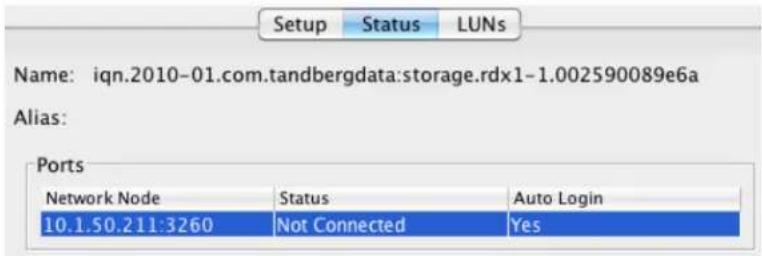
d. Select the Network Node listed and click LogIn.
The iSCSI targets are displayed with a green icon when they are connected to the RDX QuikStation.


CAUTION: Before you shut down or restart the RDX QuikStation for any reason, it is recommended that you disconnect all iSCSI targets.
Set iSCSI Security
The RDX QuikStation allows you to set iSCSI security in one of the following ways.
- CHAP Authentication – CHAP is a protocol that is used to authenticate iSCSI connections and is based upon the initiator and target sharing a secret (a security key that is similar to a password). You can add up to 10 initiator users (host computers) per iSCSI target. However, for disk configuration, only one initiator can be actively connected to the disk target at a time.
- Host Authentication – Only the initiators (host computers) that you specify for an iSCSI target will be allowed to connect to the target. Without host authentication, any network host can connect to the iSCSI target. You can add up to 10 host computers per iSCSI target. However, for all logical device configurations, only one initiator can be actively connected to the disk target.

IMPORTANT: As a best practice, set iSCSI security in the RDX QuikStation Remote Management Console first. Then, using the host's iSCSI initiator software, connect the host computer to your iSCSI targets on the RDX QuikStation.
If you do not set security in the Remote Management Console first, any previously connected hosts will remain connected to the RDX QuikStation regardless of the security you set.
This section covers the following topics:
- Setting iSCSI Security in the Remote Management Console
- Connecting iSCSI Targets with CHAP for Windows
- Connecting iSCSI Targets with CHAP for Linux
- Connecting iSCSI Targets with CHAP for Mac OS X
Setting iSCSI Security in the Remote Management Console
To set iSCSI security:
- Sign in to the Remote Management Console (see "Connect to Remote Management Console" on page 18).
-
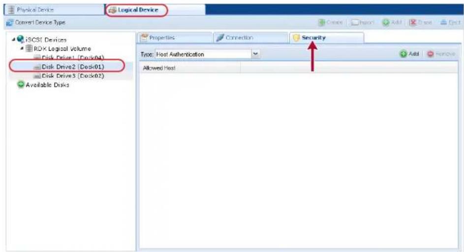
Click the Logical Device top tab, select the iSCSI target from the tree view on the left, and click the Security tab.
-
Enable your authentication.
-
To set CHAP authentication, see "Enabling CHAP Authentication" on page 31.
- To set host authentication, see "Enabling Host Authentication" on page 32.
Enabling CHAP Authentication
To add CHAP users (host computers) to an iSCSI target:
-
From the Security tab dialog window, verify that the CHAP Authentication option is shown in the drop-down menu window.
-
Click Add.

The Add ISCSI User dialog box opens.

- In the User Name field, enter the host initiator name.
By default, this is the host IQN name, which you can find from your iSCSI host initiator software application.
NOTE: You can create a unique user name in this field. If you do so, you must also change the default host initiator name in your host iSCSI initiator software to match this name.
- Enter and verity the CHAP Secret Key.
The secret must be 12 to 16 characters long. You can use any combination of letters, numbers, and the following special characters: -, !@#\$%^&*_
- Click Add.
Enabling Host Authentication
To add host computers that are allowed to connect to an iSCSI target:
-
From the Security tab dialog window, select the Host Authentication option from the drop-down menu window.
-
Click Add.

The Add iSCSI Host dialog box opens.

-
Enter the IP address for the network host.
-
Click Add.
Connecting iSCSI Targets with CHAP for Windows
The following instructions describe how to connect your network host computers in Windows Server 2012R2. Your iSCSI initiator interface may differ slightly depending on your Windows operating system.
To establish an iSCSI connection with CHAP enabled:
- After discovering all the iSCSI targets (see "Connecting iSCSI Targets for Windows" on page 23), select an iSCSI qualified name (IQN) from the list, and click Connect. The Connect To Target dialog window opens.

-
Click Advanced.
-
In the Advanced Settings dialog window, complete the following actions:

a. Check the Enable CHAP log on box.
b. Enter the CHAP Name.
The name must match the name that was set in the Remote Management Console for this particular target.
c. Enter the Target secret.
This secret must match the CHAP secret key that was set in the Remote Management Console for this particular iSCSI target.
d. Click OK.
e. At the Connect to Target dialog window, click OK again.
The RDX QuikStation's iSCSI target should display as Connected in the Discovered targets section of the ISCSI Initiator Properties > Targets window.


CAUTION: Before you shut down or restart the RDX QuikStation for any reason, it is recommended that you disconnect all iSCSI targets.
Connecting iSCSI Targets with CHAP for Linux
The following instructions describe how to connect iSCSI targets with CHAP authentication using a newly-installed Linux Open-iSCSI Initiator that is available for Redhat Enterprise Linux, CentOS, Fedora Linux, Debian, and Ubuntu operating systems.
NOTE: For more information about using an Open-iSCSI Initiator with your specific Linux operating system, refer to your Linux distribution website.
- Install Open-iSCSI Initiator.
- To install the Linux iSCSI Initiator, enter the following command:
# yum install iscsi-initiator-utils
- For Ubuntu and Debian operating systems, enter the following command:
\$ sudo apt-get install open-iscsi
- Configure CHAP authentication.
a. Open the iscsid.conf file using a vi text editor with the following command:
# vi /etc/iscsi/iscsid.conf
b. Set the authmethod to CHAP by replacing None with CHAP so that the following line reads:
node.session.auth.authmethod = CHAP
c. Set the host initiator user name and CHAP password.
Uncomment the following lines and replace the variables with the actual host initiator name and password needed to connect to the iSCSI target:
#node.session.auth.username = <host_initiator_name>
#node.session.auth.password = <CHAP_password>
#discovery.sendtargets.auth.username = <host_initiator_name>
#discovery.sendtargets.auth.password = <CHAP_password>
d. Restart the iSCSI service by entering the following command:
<h1 id="etcinitdiscsi-start">/etc/init.d/iscsi start</h1>
- Discover iSCSI targets.
To discover the RDX QuikStation iSCSI targets, enter the following command, replacing the variable
<h1 id="iscsiadm-m-discovery-t-sendtargets-p-rdx_ip_address">iscsiadm -m discovery -t sendtargets -p <RDX_IP_address></h1>
Depending on how you configured the logical device type for the RDX QuikStation, you will see one to eight iSCSI targets.
- Connect iSCSI targets.
- To connect all discovered iSCSI targets, enter the following command:
<h1 id="iscsiadm-m-node-l-all-2">iscsiadm -m node -L all</h1>
- To connect to an individual target, enter the following command, replacing
<h1 id="iscsiadm-m-node-t-target_iqn_name-p-target_portal-login-2">iscsiadm -m node -T <target_IQN_name> -p <target_portal> --login</h1>
Once all iSCSI targets are connected, the initiator (Linux host) can use the iSCSI disks as a normal disk. It appears under /dev/sdx devices and you can format or mount iSCSI disks like a normal disk.

CAUTION: Before you shut down or restart the RDX QuikStation for any reason, it is recommended that you disconnect all iSCSI targets.
Connecting iSCSI Targets with CHAP for Mac OS X
The following instructions describe how to connect your Mac OS X host computers with CHAP authentication using Atto Technology's Xtend SAN iSCSI initiator. Xtend SAN is compatible with Mac OS X 10.4.x and later. While we do not require you to use Xtend SAN as your third-party Mac OS X iSCSI initiator, we recommend that you use an iSCSI initiator that has been tested or recommended for use with your chosen backup application.
To establish a secure iSCSI connection:
-
Discover all the iSCSI targets (see "Connecting iSCSI Targets for Mac OS X" on page 27).
-
For each iSCSI target, complete the following steps to connect the target:
a. Select an iSCSI qualified name (IQN) from the left pane.
The target's port information opens.

b. Check both the Visible and Auto Login boxes.
c. Click Security.
The Configure Security dialog window opens.

NOTE: The Target User Name (the host's IQN name), must match the user name that is specified in the iSCSI Management settings of the Remote Management Console.
d. Enter the Target Secret.
This secret must match the CHAP secret that was set in the Remote Management Console for this particular iSCSI target.
e. Click OK.
f. Click the port information Status tab.
The target's connection status is displayed.
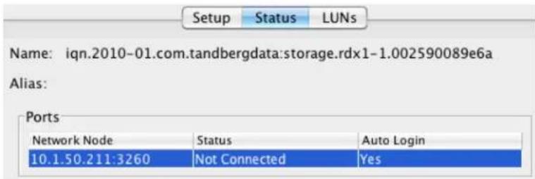
g. Select the Network Node that is shown, and click LogIn.
When connected to the RDX QuikStation, the iSCSI targets are displayed with a green icon.


CAUTION: Before you shut down or restart the RDX QuikStation for any reason, it is recommended that you disconnect all iSCSI targets.
4
System Configuration
This chapter describes the RDX QuikStation system settings that a user with administrator privileges can view and modify.
Topics in Setup and Configuration:
- System Settings Overview
- Date and Time Configuration
• Network Configuration - Notification Configuration
- User Management
- Convert Device Type
- Options for RDX QuikStation
System Settings Overview
As a user with administrator permissions, the following functions are available for you to view and modify from the Remote Management Console System Settings menu.

| System Setting Menu | |
| Name | Description |
| Date/Time Allows you to set the date, time, and NTP server for the RDX QuikStation (see “Date and Time Configuration” on page 39). | |
| Network (Information) | Allows you to modify the RDX QuikStation name, assign a static IP address, configure DNS server addressing information, and set a port bonding mode (see “Network Configuration” on page 40). |
| Notification Allows you to specify email addresses where messages for error reporting and password recovery are sent, enable SMTP authentication, and customize email sender and subject line text (see “Notification Configuration” on page 45). | |
| User Management Allows an administrator to add, remove, and edit users that are allowed access to the RDX QuikStation Remote Management Console (see “User Management” on page 47). | |
| System Setting Menu Name | Description |
| Convert Device Type | Lets you to change the logical device type for the RDX QuikStation.For more information about logical device types, see “Convert Device Type” on page 54 and Chapter 5, “Select the Logical Device Type.” |
 CAUTION:If you convert the logical device type, make sure there are no active host connections to the iSCSI targets before doing so. CAUTION:If you convert the logical device type, make sure there are no active host connections to the iSCSI targets before doing so. | |
| Options The Options dialog window is divided into three tabs: System, Removable Disk, and Diagnostics. See “Options for RDX QuikStation” on page 55 for more information. | |
Date and Time Configuration
NOTE: You must have administrator privileges to set the date and time.
To set the date the time and time for your RDX QuikStation:
- From the Remote Management Console main menu, select System Settings > Date/Time.

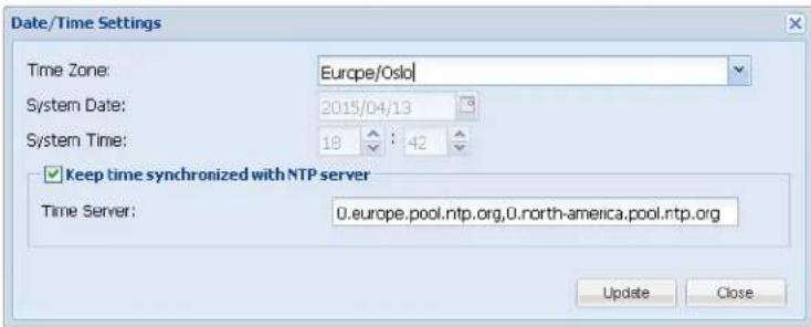
The Date/Time Settings dialog window opens.
-
Choose one of the following options to change the settings:
-
If the NTP server box is unchecked, use the drop-down list to modify the Time Zone, manually change the System Date and System Time fields, and then click Update.
- Check the Keep time synchronized with NTP server box., type one or more valid NTP server IPv4 addresses (or its fully qualified domain names) in the Time Server field, and then click Update. When entering multiple NTP server names or IQNs, separate them by commas (,).
NOTE: The RDX QuikStation hardware clock is set to use UTC (Coordinated Universal Time). When changing the time zone, click Update before changing the date and/or time. At least one city from every time zone region is listed. If your city is not listed in the drop-down menu, select a city in the same time zone. For example, the option America/Los Angeles represents the Pacific time zone which includes San Jose, San Diego, and Sacramento.
Network Configuration
NOTE: You must have administrator privileges to configure network information.
The RDX QuikStation has multiple network interfaces. These may be used as separate connections or may be “bonded” together to act as a single connection to protect against failure or to improve throughput.
NOTE: If a port is not connected to the Ethernet, be sure to set the port IPv4 setting to Disable this interface, and set the bond for that interface to None. If this is not done, it will take longer for the system to boot and, under certain circumstances, ports that are connected may not function properly.
To configure network information for the RDX QuikStation:
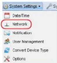
- From the Remote Management Console main menu, select System Settings > Network.
The Network Settings dialog window opens, showing only those interfaces that are not part of another bonded interface.

- If desired, you can modify the host name.
The default RDX QuikStation host name uses "vtx1u" or "vtx2u" plus the last five digits of the unit's serial number.
- To change the way in which the network interfaces are bonded, click Modify Bonding.

The Modify Bonding dialog opens.


NOTE: For QuikStation 8, the optional 10Gb Ethernet interface cannot be bonded with any of the other interfaces.

- If desired, select a new bonding configuration.
Normally, the interfaces are bonded in pairs. Bonded interfaces act like a single interface to the host (see "Port Configuration Options" on page 44 for more information). Non-bonded interfaces operate independently.
NOTE: Be sure to verify the network settings (see Step 5) for each interface whose bonding has been changed.
-
Click Change to modify the bonding settings and return to the Network Setting dialog. Bonding changes are not made permanent until all the network settings are saved.
-
To change the network settings, click the Edit icon to display the Modify Network Interface Settings page.
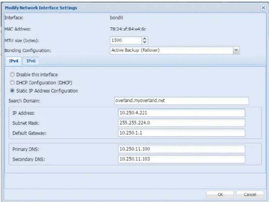
- Set the MTU size used for the rest of the network (1500 to 9000 bytes).
The default value is 1500 bytes. All devices sharing a network should have the same MTU setting.
- If you are configuring a bonded setup, select a bonding configuration.
By default, the port setting is set for Active Backup or Failover. In most cases, this default setting suffices for your network environment. See “Port Configuration Options” on page 44 for more information.
- Choose to either obtain network addressing automatically via DHCP or set static addressing information.
It is recommended you set a static IP address to prevent inadvertent address changes.
- When DHCP configuration is selected, the DHCP server in your network should provide all required information to configure network interfaces. No additional setting is required.
-
When static IP address is selected, the IP address and Subnet mask must be set. DNS and Search Domains may only be set if the Default Gateway is set. Only one Default Gateway may be set for all interfaces.
-
If you have selected Static IP Address Configuration, enter the IP address, the subnet mask, and the default gateway.
NOTE: You can configure DNS and search domain only for static configuration with gateway address set.
a. Add or modify the search domain (DNS lookup domain).
b. Enter a primary and secondary DNS server address.
c. Add or modify the search domain (DNS lookup domain).
d. Click OK.
NOTE: If you change the IP address and the Remote Management Console is not connected within 3 minutes after reboot procedure started, close web browser window and open a new one with IP address you've configured.
After the unit has been rebooted, you can verify the changes. From the System Settings > Network Settings dialog, select Information to display the Active Network Interface Settings dialog.
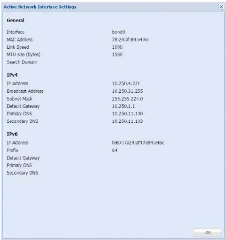
- Press OK to close.
Port Configuration Options
The RDX QuikStation 4 has two Gigabit Ethernet ports to provide failover protection and high availability network connectivity. The RDX QuikStation 8 has four Gigabit Ethernet ports standard. In network environments, it is a common practice to configure two or more external ports as a single, logical, bonded port using an industry standard feature called Link Aggregation, also known as port bonding or port trunking.
An optional 10Gb Ethernet port is also available for the RDX QuikStation. This port cannot be bonded with any other port.
Bonded Network Configuration
The behavior of the logically-bonded ports depends upon the mode. For the RDX QuikStation, you can configure port bonding for active backup/failover, adaptive load balancing, or dynamic link aggregation.
The following table describes the port bonding modes that are available in the RDX QuikStation.
| Port bonding mode Description |
| Active-backup (failover) The Active-backup or failover mode is the default configuration for the RDX QuikStation. This mode uses one port (adapter) and is limited by that port's throughput. It will only switch to the other port if the active port fails. |
| Port bonding mode Description | |
| Adaptive load balancing (balance-alb) | Adaptive Load Balancing provides load balancing of transmit and receive traffic. It also provides automatic failover if one cable fails. This option works with any switch and is best used in a multi-disk environment that has multiple iSCSI host connections. This mode can provide a maximum performance for multiple iSCSI sessions from the different IP addresses. You might consider using this option if you have configured your RDX QuikStation as the maximum number of RDX drives, and you are using most or all of the iSCSI disk targets. |
| Dynamic link aggregation (802.3ad) | Creates aggregation groups that share the same speed and duplex settings. Utilizes all slave network interfaces in the active aggregate group according to the IEEE 802.3ad specification.Requires 802.3ad support in Ethernet switch and host computer (iSCSI initiator). This mode shall be utilized as point-to-point between RDX QS 4 and the initiator host. This mode can provide a maximum performance for a multiple iSCSI sessions from the same IP address.If the network is not configured properly, using this port bonding mode can disrupt the entire network. |
Split Network Configuration
When there is more than one Ethernet interface available to the host, each available interface is configured separately. Configuration of each separate interface is similar to the configuration of a single bonded interface above with a few exceptions:
- An unbonded interface dialog has no bonding mode settings.
- IP address must be different for all interfaces.
- Only one default interface can have gateway address set.
- If one interface is set in DHCP mode, it is considered a default interface.
- At least one interface must be enabled in a split setup.
- You can configure DNS and search domain only for interface with static configuration, which has gateway address set.
NOTE: A split Ethernet port configuration should be used if ports are connected to the different networks. If ports are connected to the same network setup, use a bonded port configuration. You may also want to use split Ethernet connection if you choose to allow the Multiple Host Connections option. See “Options for RDX QuikStation” on page 55.
Notification Configuration
NOTE: You must have administrator privileges to set email notifications.
The Notifications Settings dialog window consists of three tabs: basic, authentication, and customization. If your email server requires it, the Authentication tab allows you to add a user name and password for SMTP authentication. The Customization tab allows you to define the "From" email address and the subject text for email messages that are sent by the RDX QuikStation.
NOTE: If the network is set to a static IP address, the Default Gateway, Search Domain, and primary DNS server may have to be set to access the email server.
Setting Basic Email Notification
- From the Remote Management Console main menu, select System Settings > Notification.

The Notification Settings dialog displays.

- Type one or two valid email addresses in the email recipient fields. The RDX QuikStation will send any system error messages, such as a fan failure or an RDX dock failure, to the addresses that you specify. The RDX QuikStation will also send any password recovery requests to these addresses.
- Enter a fully-qualified email server domain name. For example, mailhost.mycompany.com. You can also enter a valid IPv4 address. For example, 192.168.1.101.
- If your email server uses SSL/TSL, check the box to enable it.
- Click Change.
Setting SMTP Authentication
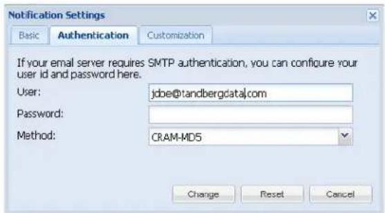
- From the Notification Settings dialog window, click the Authentication tab.
-
Type the SMTP user name and password for your email server.
-
From the drop-down menu, select the authentication method – either Plain or CRAM-MD5.
-
Click Change.
Customizing Email Subject and From Address
- From the Notification Settings dialog, click the Customization tab.

- Type your desired From email address using standard email format.
For example, myQuikStation@mycompany.com. The From email text does not need to be a valid email address.
- If desired, type a custom subject text.
This text is used in all emails that are generated by your RDX QuikStation.
- Click Change.
User Management
NOTE: You must have administrator privileges to manage user groups.
The RDX QuikStation allows you to set up three types of groups: administrator, manager, and user. This section covers:
• Group Permissions Overview
- Adding Users to a Group
- Removing Users from a Group
• Editing User Information
• Recovering the Built-In Administrator Password
Group Permissions Overview
The RDX QuikStation Group Permissions table describes the functionality each group can access in the Remote Management Console.
| User Manager Administrator | ||
| Users have permission to do the following:change their log-in password.view physical and logical device information.refresh/update device information manually. | Managers have permission to do the following:view group information.view iSCSI Management security and connection status.set options for diagnostic log level.change their log-in password.view physical and logical device information.refresh/update device information manually. | Administrators have access to all functionality. This includes permission to:set system and network configuration.set iSCSI security.add, remove, and edit groups.format/erase RDX media.clone data on RDX media.convert logical device type.update firmware.perform system diagnostic tests.access all other system maintenance tasks. |
Adding Users to a Group
To add users to a group:
- From the Remote Management Console main menu, select System Settings > User Management.
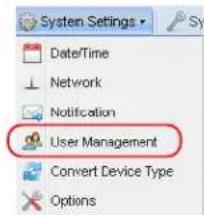
The User Management dialog window opens.

-
Click Add.
-
Type a user name and password in the applicable fields.
The following conditions apply:
- User names are not case sensitive and can only contain letters, numbers, and the underscore (_) character. Names are limited to 80 characters in length.
- Passwords are case sensitive and must be 6 to 30 characters long. Passwords can contain any combination of letters, numbers, and the following special characters: -, !@#\$%^&*_
-
From the drop-down menu, select the group to which you want to assign the user. For a description of the permissions available to each group, see "Group Permissions Overview" on page 47.
-
If desired, type a description to identify the user.
-
Click Add.
Removing Users from a Group
To remove users from a group:
-
From the Remote Management Console main menu, select System Settings > User Management.
-
From the User Management dialog, select the user that you want to remove.
-
Click Remove.

The User Account Control window displays.
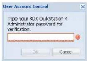
-
Enter your RDX QuikStation Administrator password, and click OK.
-
Click Yes to confirm.
Editing User Information
You can edit a user name, the group assignment, description, and password.
NOTE: For the built-in administrator account, you can only edit the password.
Editing the User Name, Group, or Description
-
From the Remote Management Console main menu, select System Settings > User Management.
-
From the User Management dialog, double-click in the field you want to edit.
The field becomes editable.
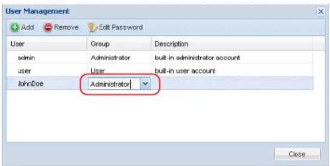
- Make your desired changes, and press Enter.
NOTE: User names can only contain letters, numbers, and the underscore (_) character. Names are limited to 80 characters in length.
Editing a Password
NOTE: For users assigned to administrator and manager groups, you must first enter your RDX QuikStation administrator password before editing the password.
- From the Remote Management Console main menu, select System Settings > User Management.
- From the User Management dialog, select the user.
- Click Edit Password to open the change dialog.
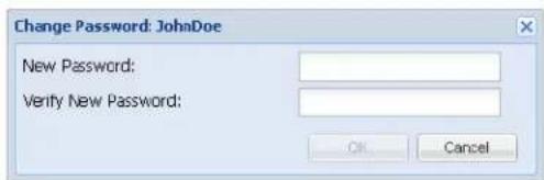
- Type a new password, type the password again to verify, and click OK.
Passwords are case sensitive and must be 6 to 30 characters long. Passwords can contain any combination of letters, numbers, and these special characters: - , !@#\$%^&*_.
Recovering the Built-In Administrator Password
NOTE: The built-in administrator user name is admin (cannot be modified) and the default password is Admin! (case sensitive).
If you have forgotten the built-in administrator password you created, you can reset the password via email or via USB.
If you have forgotten the user name and password for any other account, to edit the password either contact the RDX QuikStation administrator or sign in as the built-in administrator account (see "Editing a Password" on page 50).
Resetting the Password via Email
- From the RDX QuikStation sign-in dialog, click the question mark (?) in the upper-right corner.
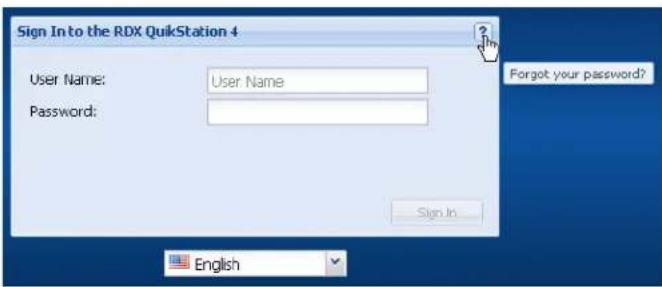
The Password Reset dialog is shown.

- Select the Administrator option.
- Click Continue.
The Administrator Password Reset dialog opens.

- Select Request Key.
The RDX QuikStation sends an email message to the address that was specified in the Remote Management Console (see "Notification Configuration" on page 45). The request key remains valid for one hour.
- Click OK and leave the Administrator Password Reset dialog open.

IMPORTANT: If you close the browser session, the request key that was sent via email becomes invalid.
- Copy the request key from the email message and paste it into the Reset Key field.

- Type a new password, type the password again to verify, and click OK.
Passwords are case sensitive and must be 6 to 30 characters long. Passwords can contain any combination of letters, numbers, and these special characters: - , !@#\$%^&*_.
Resetting the Password via USB
If an email notification address is not specified in the Remote Management Console, you can reset the built-in administrator password via USB by creating a password.reset file.

IMPORTANT: The Overland-Tandberg-supplied USB flash drive might include configuration example files. Change file extensions to *.example to make sure the correct action would be formed by RDX QuikStation firmware.
To create the password.reset file and reset the password via USB:
- Insert the USB flash drive that was included in your RDX QuikStation accessory kit box into your computer.
If you cannot find the flash drive, you can use any USB flash drive that is formatted with a VFAT32 or NTFS file system.
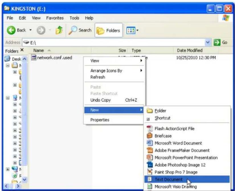
- Navigate to the flash drive and create a blank text file on the drive.
In Windows, right-click in the directory window, and select New > Text Document.
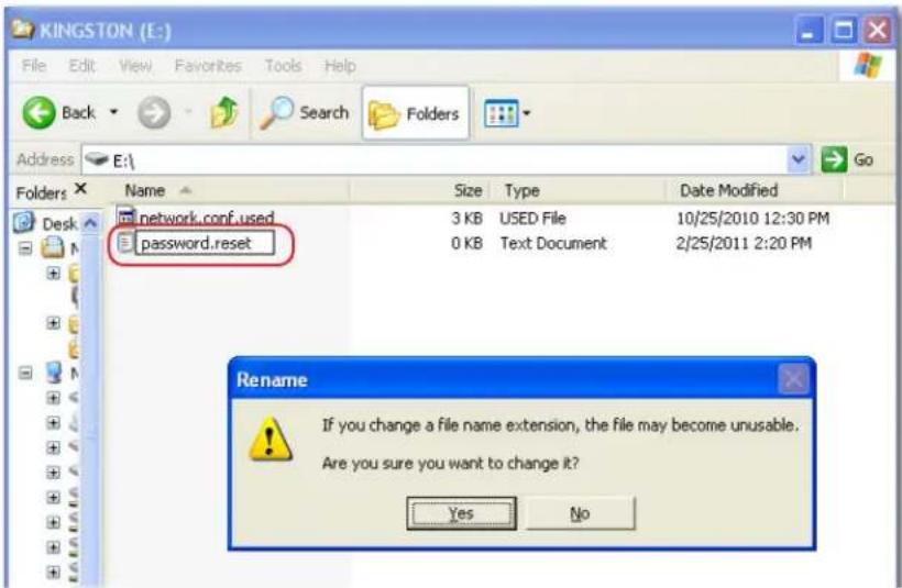
- Rename the text file to password.reset. (In Windows, click Yes to confirm the file name change.)
- Remove the USB flash drive from your computer and insert it into the RDX QuikStation USB slot located on the center-front panel.
- After 30 seconds, remove the USB flash drive.
- Connect to the RDX QuikStation Remote Management Console.
- From the Sign-in dialog, click the question mark (?) in the upper-right corner.
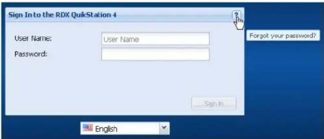
- Select the Administrator option, and click Continue. The Administrator Password Reset dialog opens.

-
In the Reset Administrator Password via USB section, click Reset Password.
-
Type a new password, type the password again to verify, click Reset, and click OK. Passwords are case sensitive and must be 6 to 30 characters long. Passwords can contain any combination of letters, numbers, and these special characters: - , !@#\$%^&*_.
Convert Device Type
To select or change the logical device type, from the Remote Management Console main menu, select System Settings > Convert Device Type.
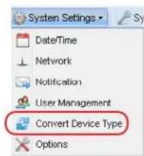
For more information, refer to Chapter 5, "Select the Logical Device Type."
Options for RDX QuikStation
The Options dialog window is divided into four tabs: System, Removable Disk, Automation, and Diagnostics. Refer to the table below for information about each tab.
| Tab Option Description | ||
| System Check firmware update automatically | Recommended. Provides notifications about new firmware releases on Internet-accessible networks. | |
| Allow multiple host connections | Allows multiple iSCSI connections to drive targets from multiple hosts in cluster environments when hosts can manage drive access. To avoid data corruption, multiple iSCSI initiator sessions should only be enabled when operating in a cluster aware filesystem. This option also supports MPIO for a single host by allowing multiple connections from the host. | |
| Removable Disk Unsafe Eject Allows you to enable the “Unsafe Eject” mode for RDX media that have an established host connection (see “Setting Removable Disk Options” on page 56. | ||
| Automation Auto-Insert Options Allows you to enable the “Auto-Insert” mode tape automation devices. If set, then cartridges physically inserted in the QuikStation docks will be logically placed in an empty tape library rather than in the Import/Export slot (see “Setting the Auto-Insert Option” on page 57. | ||
| Diagnostics Log Level Allows you to change the log level from Normal to Detail or Extend. Tandberg Data recommends you only change the log level if you are instructed to do so by Tandberg Data Technical Support.NOTE: If you change the log level, the system will default to “normal” once the Management Console browser session is closed. | ||
To access the Options dialog, from the Remote Management Console main menu, select System Settings > Options.

The Options dialog window opens with the System tab selected.
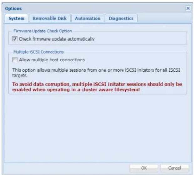
The default setting for Check firmware update automatically is selected. This setting is recommended to receive notifications about new firmware releases on Internet-accessible networks.
The Allow multiple host connections setting defaults to OFF.

CAUTION: This option should only be enabled if the QuikStation is in a clustered environment where the hosts can properly share a single storage device without causing data corruption.
When set, this option allows more than one host to access the storage device at the same time.
Setting Removable Disk Options
NOTE: The removable disk option only applies to disk configurations.
You can enable the Unsafe Eject Button Option for RDX media that have an established host connection.
By default, when an RDX dock is configured as a logical disk drive that is connected to a host computer, you cannot manually eject the media using either the RDX dock eject button or the eject function in the Remote Management Console. This is because the connected host computer's operating system has reserved the RDX media.
A fixed disk operation mode can also be used for Windows backup support.
Enabling the unsafe eject option allows you to override the default and manually eject an RDX media. This option is not recommended because you could potentially lose data on the RDX media if you use unsafe eject. We recommend that you eject the RDX media from your backup software application or from the host computer's eject function.

CAUTION: When using this operation mode, do not eject any RDX media while data is being written or read as it might cause data loss and file system corruption.
To enable Unsafe Eject Button Option:
- From the Options dialog window, click the Removable Disk tab.

-
Check the Enable Unsafe Eject box.
-
Click OK.
Setting the Auto-Insert Option
The Auto-Insert option (IE) controls how the RDX QuikStation handles tape library import/export slot functionality.
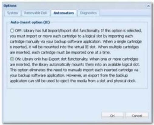
Auto-Insert Option ON
This is the default setting. When one or more RDX cartridges are inserted, the RDX QuikStation automatically moves them into an available logical slot.
The Auto-Insert option eliminates the need to use your backup software to import each inserted cartridge. If the slot corresponding to the physical dock is available, that slot will be used by the RDX QuikStation. However, you can still perform an export from the backup application to eject the media from a slot and physical dock.
This is a logical view of a tape library with the Auto-Insert option turned ON. Note that cartridges automatically mount to logical slots that correspond with their physical dock locations.

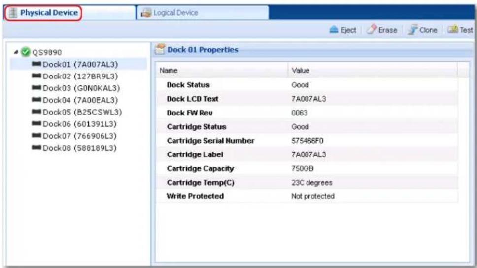
This is a physical view of a tape library with the Auto-Insert option turned ON. Note that the cartridges' physical locations correspond with their logical tape slot locations.
Auto-Insert Option OFF
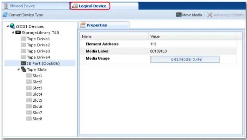
When a single RDX cartridge is inserted into any dock, it is mounted into the virtual IE port awaiting an import command from your backup software. When multiple cartridges are inserted, the first cartridge that is detected by the library is mounted to the virtual IE port. The remaining cartridges will not display in the Remote Management Console until you import them one at a time via your backup software application.
This is a logical view of a tape library with the Auto-Insert option turned OFF. Note that only the IE Port displays as populated until you import the other cartridges one at a time with your backup software.
This is a physical view of a tape library with the Auto-Insert option turned OFF. Note that four cartridges are displayed in their physical slots.
NOTE: Refer to your backup software documentation for tape library import/export commands and recommended use.
Change Auto-Insert Option
- From the Options dialog window, click the Automation tab.
- Select your desired setting (ON/OFF).
- Click OK.
5
Logical Device Management
This chapter describes the Remote Management Console Logical Device interface.
Topics in Setup and Configuration:
• Logical Device Type Overview
- Select the Logical Device Type
- RDX Targets
- Logical Volumes
- Protected Volumes
- Disk Autoloader
Logical Device Type Overview
The following table compares the logical device types that the RDX QuikStation can emulate.
| Logical Device Type | QuikStation 4 QuikStation 8 iSCSI Targets | Reported Inquiry String | ||
| RDX drives Four Fixed Disk Target | RDX drives (may be set to fixed disk mode; refer to “RDX Fixed Logical Volume” on page 63) | Eight RDX drives (may be set to fixed disk mode; refer to “RDX Fixed Logical Volume” on page 63) | One target for each RDX drive | RDX |
| Logical Volume Fixed Disk Target | Up to four RDX cartridges as a single fixed disk target | Two volumes with up to four RDX cartridges presented as two fixed disks targets | Each volume is one target | RDX |
| Logical Volume Removable Disk Target | Up to four RDX cartridges as a single removable disk target | Two volumes with up to four RDX cartridges presented as two removable disks targets | Each volume is one target | RDX |
| Protected Volume Fixed Disk Target | Up to four RDX cartridges presented as a single fixed disk target with one-disk fault tolerance | One volume with up to eight RDX cartridges presented as a single fixed disk target with two-disk fault tolerance-OR-Two volumes with up to four RDX cartridges presented as two fixed disks targets each with one-disk fault tolerance | Each volume is one target | RDX |
| Protected Volume Removable Disk Target | Up to four RDX cartridges presented as a single removable disk target with one-disk fault tolerance | One volume with up to eight RDX cartridges presented as a single removable disk target with two-disk fault tolerance-OR-Two volumes with up to four RDX cartridges presented as removable disks targets each with one-disk fault tolerance | Each volume is one target | RDX |
| Disk Autoloader | One removable disk and four slot | One removable disk and eight slots | One disk target RDX | |
| Tandberg Data StorageLoader LTO | N/A Emulated Tape Library with one tape drive and eight storage slots | Library target LTO target | StorageLoader Ultrium 3-SCSI | |
| Tandberg Data Storage Library 224 | N/A Emulated Tape Library with two tape drives and eight storage slots | Library target Two LTO targets | Magnum 224 Ultrium 3-SCSI | |
| Hybrid: TD StorageLoader and 4 RDX Drives | N/A Emulated Tape Library with one tape drive and four storage slots, plus four RDX drives | Library target LTO target Four RDX targets | StorageLoader Ultrium 3-SCSI RDX | |
Select the Logical Device Type
To configure the logical device type:
- Select the device type from the dialog that opens when you first log on to the Remote Management Console.
If you select the RDX Drive configuration, you should first install the RDX Utility, which is available from www.tandbergdata.com. A link (Here) is also provided in the Logical Device Type Settings dialog.
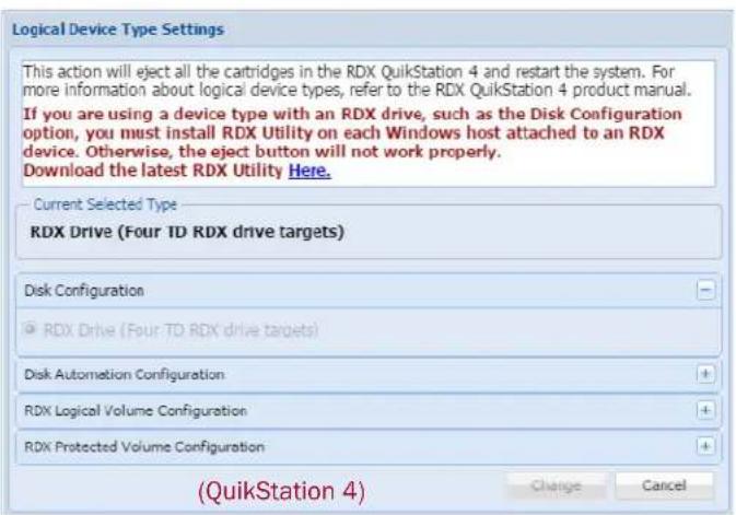

- Click Change.
RDX Targets
This configuration presents each QuikStation RDX dock to the computer host as a individual iSCSI RDX dock.
RDX Individual Dock Drives
By default the target acts like a normal RDX removable disk. Optionally, you can set each RDX target to appear as a fixed disk to the host using the Advance Options button for the drive. In some environments, this allows both faster read and write times when connected to Windows OS and the use of RDX media with Windows-native backup applications.
- From the Logical Device tab, select an available disk and click Advanced Options.

The Advanced Options dialog opens.

- Check the Present the disk as a fixed disk on the network box, and click OK.
RDX Logical Volume
The RDX Logical Volume combines up to either 4 RDX media (for the QuikStation 4) or 8 RDX media (for the QuikStation 8) into a single logical volume target. This configuration allows you to manage a single logical volume comprised of one or more of the RDX media in your system.
The RDX Logical Volume may be presented to the host as either a fixed disk or as an RDX device.
RDX Fixed Logical Volume
The Fixed Disk RDX Logical Volume is presented as fixed disk to the host computer. This means that the host computer will not expect the disk to be removed. The user interface software will not allow the logical volume to be ejected while it has an iSCSI connection to a host.
The Fixed Disk RDX Logical Volume may have faster write times than the Removable Disk RDX Logical Volume for some host operating systems.

In the QuikStation 8, you can configure two Fixed Disk RDX Logical Volumes. Each volume consists of up to four RDX cartridges either on the top or the bottom row.
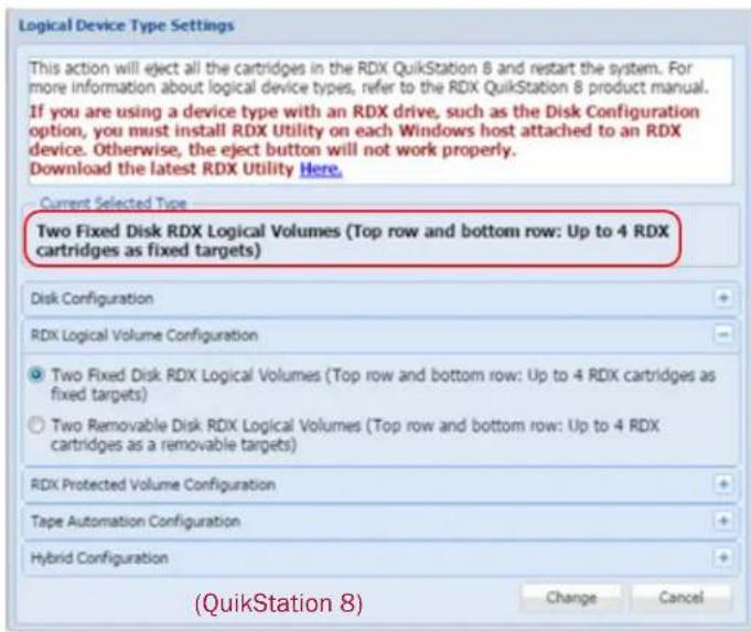
RDX Removable Logical Volume
The Removable Disk RDX Logical Volume is presented as an RDX removable disk to the host computer. This means that the host computer expects that the disk may be removed. The host operating system may allow ejection of the device from the host. The user interface software will allow the logical volume to be ejected while it has an iSCSI connection to a host as long as the host software has allowed the removal.
When the RDX Logical Volume is ejected all RDX cartridges in the logical volume are ejected.
The Removable Disk RDX Logical Volume may have slower write times than the Fixed Disk RDX Logical Volume for some host operating systems.
Since the RDX Logical Volume is presented as an actual RDX device, it will work with any host software that can utilize an RDX drive.
NOTE: If you select the RDX Removable Logical Volume configuration, you should first install the RDX Utility, which is available from www.tandbergdata.com. A link is also provided in the Logical Device Type Settings dialog.
The Removable Disk RDX Logical Volume is presented as a single RDX device. Even if no logical volume is present in the system, an RDX dock device will be available to the host iSCSI initiator. In this case the virtual dock will appear to be empty.

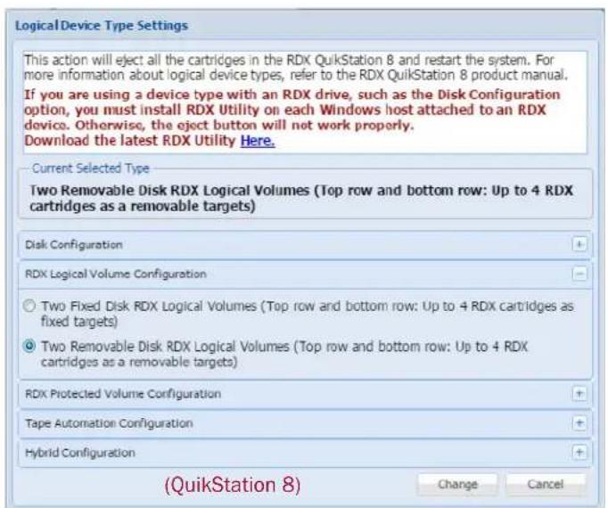
Logical Volumes
RDX drives can be configured as logical volumes that combine the capacity of the RDX media available.
Creating a Logical Volume
If no logical volume is currently present, you can create a logical volume.
- From the Logical Device tab, select an available disk.

- Click Create to open the Create a Logical Volume dialog.

The Create a Logical Volume dialog allows you to select which available disks to use to create the logical volume.
NOTE: Write-protected and damaged media are not allowed in this operation.
- Select the docks to use in the logical volume, and click Create.
The logical volume is created.
Importing a Logical Volume
If no logical volume is currently present, you can also import a logical volume created on this or another RDX QuikStation unit.
-
Insert all RDX media belonging to this logical volume.
-
From the Logical Device page, select one of the available disks that has a Logical Volume UUID, and click Import.

- At the Import Logical Volume dialog, click Import to accept the import operation.
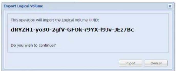
The logical volume will be ready to use if all the disks that comprise the Logical Volume are present.
Expanding a Logical Volume
If the logical volume contains fewer than eight disks for the QuikStation 8 or four disks for the QuikStation 4, you can expand it.
NOTE: The logical volume must be disconnected from any iSCSI host prior to adding available disks to the logical volume.
- Select an available disk and click the Add button.

The Add dialog allows you to select which available disks to add to the logical volume.
NOTE: Write-protected and damaged media are not allowed in this operation.
- Select the disks to be added by checking the Add boxes.
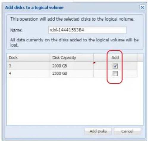
- Click Add Disks to complete the process.
Once the logical volume has been expanded, the iSCSI host is responsible for expanding the file system on the volume to take advantage of the extra space. How this is accomplished is dependent on the host operating system. Refer to the administrator's guide for your operating system.
Erasing a Logical Volume
The entire logical volume can be also be erased using Erase.
NOTE: The logical volume must be disconnected from any iSCSI host prior to erasing the logical volume.
To erase an entire logical volume:
- From the Logical Device dialog, select the logical volume and click Erase. The Remove all Logical Volume information dialog is shown.

- Click Remove.
Once all logical volume information is removed, all disks will be shown as Available Disks.
NOTE: If you need a secure data erase, please use tools designated for that purpose. Actual data is not erased on the RDX Media, only the partition table on the disk and LVM metadata.
Exporting the Logical Volume
The logical volume may be exported by using the logical volume Eject button.
NOTE: The logical volume should be disconnected from any iSCSI host prior to ejecting the logical volume.
- From the Logical Device interface, select the logical volume to export and select Eject.

Tip: Print or copy the Eject dialog information to keep with the logical volume disk set after it is ejected.
- At the Eject Logical Volume dialog, click OK to confirm.
Once the logical volume disks have been ejected, they should be carefully marked and kept as a set. The disk set, if complete, may be imported into this or any other RDX QuikStation.
When an RDX Logical Volume is ejected, the Logical Devices will show an empty logical volume.

NOTE: For a Removable Disk RDX Logical Volume, you can also export the logical volume by using the 'eject' facility of the host operating system.
Protected Volumes
RDX drives can be configured as protected volumes that combine the capacity of the RDX media available and will continue to function even if one of the RDX cartridges fails.
RDX Protected Volume
In the QuikStation 4, the RDX Protected Volume combines up to four RDX media into a single protected volume target which continues to function even if one of the RDX cartridges fails. This configuration allows you to manage a single protected volume comprised of one or more of the RDX media in your system with one-disk fault tolerance. The Protected Volume must contain at least three disks.
In the QuikStation 8 the RDX Protected Volume combines up to eight RDX media into a single protected volume target which continues to function even if two of the RDX cartridges fail. This configuration allows you to manage a single protected volume comprised of four or more of the RDX media in your system with two-disk fault tolerance. In addition, the QuikStation 8 also supports two four-disk Protected Volumes with one-disk fault tolerances.
An RDX Protected Volume may be presented to the host as either a fixed disk or as an RDX device.
NOTE: Adding fault protection to a volume requires some data redundancy. The loss of storage capacity may be roughly estimated as the capacity of the fault tolerated disks in the volume. When creating an RDX Protected Volume the size of the available space is dependent on the size of the smallest disk used to create the volume. It is strongly advised to use disks which are all the same size to create the protected volume.
RDX Fixed Protected Volume
The Fixed Disk RDX Protected Volume is presented as fixed disk to the host computer. This means that the host computer will not expect the disk to be removed. The user interface software will not allow the protected volume to be ejected while it has an iSCSI connection to a host.
The Fixed Disk RDX Protected Volume may have faster write times than the Removable Disk RDX Protected Volume for some host operating systems.

In the QuikStation 8, you can configure two Fixed Disk RDX Protected Volumes with one-disk fault tolerances. Each volume consists of up to four RDX cartridges either on the top or the bottom row. In addition, you can configure a single Fixed Disk RDX Protected Volume with two-disk fault tolerance consisting of up to eight RDX cartridges.

RDX Removable Protected Volume
The Removable Disk RDX Protected Volume is presented as an RDX removable disk to the host computer. This means that the host computer expects that the disk may be removed. The host operating system may allow ejection of the device from the host. The user interface software will allow the protected volume to be ejected while it has an iSCSI connection to a host as long as the host software has allowed the removal.
When the RDX Protected Volume is ejected, all RDX cartridges in the protected volume are ejected.
The Removable Disk RDX Protected Volume may have slower write times than the Fixed Disk RDX Protected Volume for some host operating systems.
Since the RDX Protected Volume is presented as an actual RDX device, it will work with any host software that can utilize an RDX drive.
NOTE: If you select the RDX Removable Protected Volume configuration, you should first install the RDX Utility, which is available from www.tandbergdata.com. A link is also provided in the Protected Device Type Settings dialog.
The Removable Disk RDX Protected Volume is presented as a single RDX device. Even if no protected volume is present in the system, an RDX dock device will be available to the host iSCSI initiator. In this case the virtual dock will appear to be empty.

In the QuikStation 8, you can configure two Removable Disk RDX Protected Volumes. Each volume consists of up to four RDX cartridges either on the top or the bottom row.

Creating a Protected Volume
If no protected volume is currently present, you can create a protected volume:
1. From the Logical Device tab, select an available disk
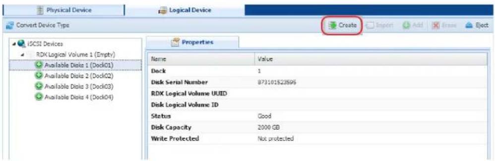
2. Click Create to open the Create a Protected Volume Array dialog.
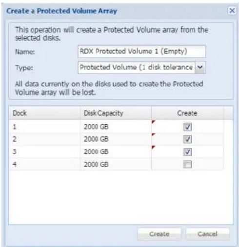
The Create a Protected Volume Array dialog allows you to select which available disks to use to create the protected volume.
NOTE: Write-protected and damaged media are not allowed in this operation.
3. Select the docks to use in the protected volume, and click Create.
Importing a Protected Volume
If no protected volume is currently present, you can also import a protected volume created on this or another RDX QuikStation.
-
Insert all RDX media belonging to this protected volume.
-
From the Logical Device page, select one of the available disks that has a Protected Volume UUID, and click Import.

- At the Import Protected Volume Array dialog, click Import to accept the import operation.

The protected volume is ready to use.
Expanding a Protected Volume
If the protected volume contains fewer than the maximum number of disks, you can expand it.
NOTE: The logical volume must be disconnected from any iSCSI host prior to adding available disks to the logical volume.
- Select an available disk and click the Add button.

The Extend dialog allows you to select which available disks to add to the protected volume.
NOTE: Write-protected and damaged media are not allowed in this operation.
- Select the disks to be added by checking the Add boxes.

- Click Add Disks to complete the process.
Once the protected volume has been expanded, the iSCSI host is responsible for expanding the file system on the volume to take advantage of the extra space. How this is accomplished is dependent on the host operating system. Refer to the administrator's guide for your operating system.
Expanding a Fixed Logical Volume File System for a Window Host
When one or more disks are added to an existing RDX Logical Volume, the file system on that logical volume is not enlarged. That must be done by the host file system handler.
For a Windows host, the file system on an RDX Fixed Logical Volume can be expanded as described below. Expanding the file system leaves all current data on the volume intact.
For a Windows host:
- Use the iSCSI initiator to reconnect to the expanded volume.
2. Open the Disk Management tool.
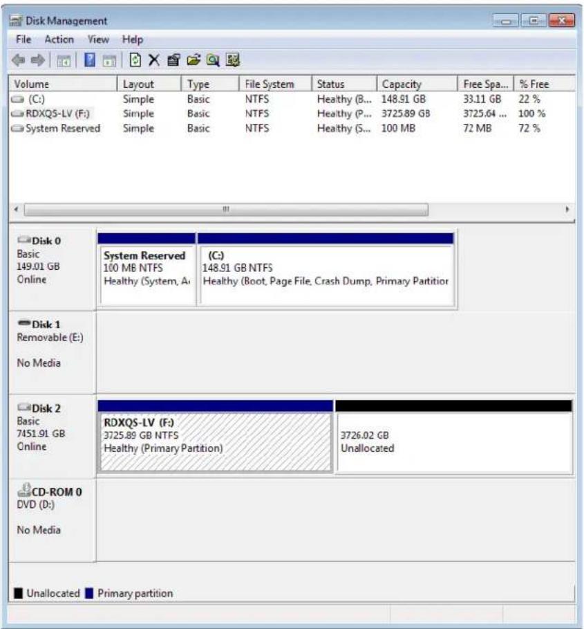
- Right-click the logical volume and select Extend Volume.
- In the Extend Volume Wizard, use the defaults to fully extend the file system by clicking Next.
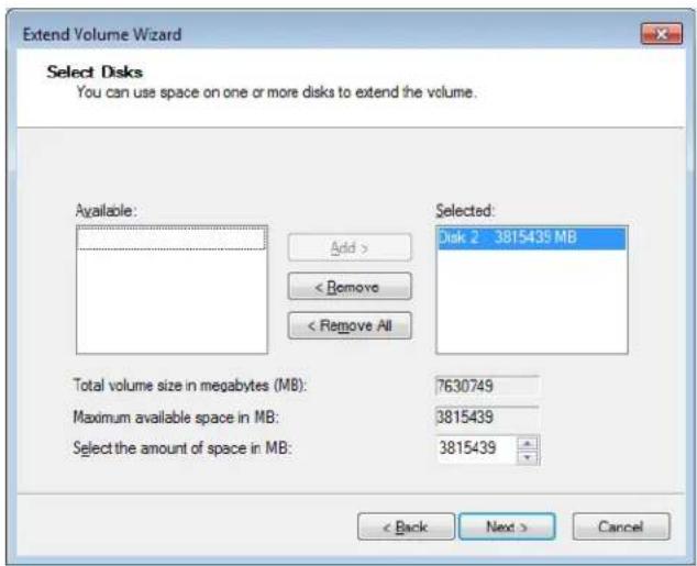
The extension is completed.
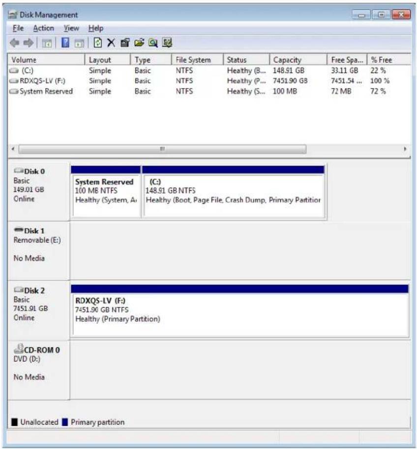
Expanding a Removable Logical Volume File for a Windows Host
When one or more disks are added to an existing RDX Logical Volume, the file system on that logical volume is not enlarged. That must be done by the host file system handler.
Windows does not allow extension of a removable disk. Therefore the following procedure must be followed to extend a Removable RDX Logical Volume.
-
Disconnect the host iSCSI initiator from the Removable RDX Logical Volume.
-
Add one or more disks to the Removable RDX Logical Volume from the User Interface.
-
Use Convert Device Type to convert the RDX QuikStation to Fixed Disk RDX Logical Volume.
-
Import the RDX Logical Volume in the Logical Device pane of the User Interface.
-
Clear the IQN of the Removable RDX Logical Volume. The Fixed RDX Logical Volume will have a different IQN than the Removable RDX Logical Volume, so the old IQN must be cleared from the initiator first.
-
Connect the host iSCSI initiator to the Fixed RDX Logical Volume.
-
Follow the instructions in "Expanding a Fixed Logical Volume File System for a Window Host" on page 75.
-
Disconnect the host iSCSI initiator from the Fixed RDX Logical Volume.
- Use Convert Device Type to convert the RDX QuikStation to Removable Disk RDX Logical Volume.
- Import the RDX Logical Volume in the Logical Device pane of the User Interface.
- Clear the IQN of the Fixed RDX Logical Volume.
The Removable RDX Logical Volume will have a different IQN than the Fixed RDX Logical Volume, so the old IQN must be cleared from the initiator first.
- Connect the host iSCSI initiator to the Removable RDX Logical Volume.
Erasing a Protected Volume
The entire protected volume may also be erased using the Erase button.
NOTE: The protected volume must be disconnected from any iSCSI host prior to erasing the protected volume.
To erase an entire protected volume:
- From the Protected Device dialog, select the protected volume and click Erase. The Remove all Protected Volume Array Information dialog is shown.
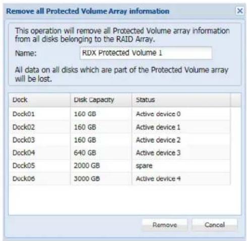
- Click Remove.
Once all protected volume information is removed, all disks will be shown as Available Disks.
NOTE: If you need a secure data erase, please use tools designated for that purpose. Actual data is not erased on the RDX Media, only the partition table on the disk and LVM metadata.
Exporting the Protected Volume
NOTE: The protected volume should be disconnected from any iSCSI host prior to ejecting the protected volume.
A RDX Protected Volume can be exported by using the protected volume Eject option.
NOTE: For a Removable Disk RDX Protected Volume, you can also export the protected volume by using the 'eject' facility of the host operating system.
- From the Protected Device interface, select the protected volume to export and select Eject.
The Eject Protected Volume Array dialog is shown.

-
To create a copy of the Eject Protected Volume Array dialog information to keep with the protected volume disk set after it is ejected, click Print.
-
Click OK to confirm the ejection.
Once the protected volume disks have been ejected, they should be carefully marked and kept as a set. The disk set, if complete, can be imported into this or any other RDX QuikStation later.
When a RDX Protected Volume is ejected, the Protected Devices list shows no protected volumes and is marked as (Empty).

Recovering a Degraded Protected Volume
If a protected volume disk has failed, and the volume is in 'Degraded' status, you may restore the volume to full functionality by replacing the faulty disk.
-
Remove the faulty disk from the QuikStation.
-
Put a new disk of equal (or greater) size in the QuikStation
-
From the Protected Device interface, select the new disk, and click Add.

NOTE: Write-protected and damaged media are not allowed in this operation.
- At the Add disk to repair a degraded Protected Volume array dialog, select the disk being added.

- Click Fix to begin the recovery process.

The recovery process may take a considerable amount of time but the protected volume may be used while the rebuilding proceeds. Once recovery is complete, the protected volume will no longer be degraded.
NOTE: Only one disk may be added to a degraded Protected Volume at a time.
Disk Autoloader
When the QuikStation is configured as a Disk Autoloader, the host will primarily see an iSCSI removable disk target. When the host software ejects an RDX medium from the disk target, the autoloader will virtually "move" the next disk into the disk target. The disk target will become ready and the host software can continue operation.
Depending on the setting of the Autoloader Continuous Rotate option, the host ejection of RDX media can cause a physical ejection or simply a logical removal.
The autoloader is also presented as an iSCSI target. However, there is no need for the host to interact with this device since normal logical motions are handle by the autoloader independently. The autoloader iSCSI target is presented mainly for diagnostic purposes.

In the Logical Device tab, the home slot for the currently loaded disk is indicated with a blue arrow (☐).
If the Autoloader Continuous Rotate option is OFF, when the disk is instructed to eject, the medium is physically ejected, and the next disk below the ejected one is logically loaded.
If the Autoloader Continuous Rotate option is ON, when the disk is instructed to eject, the medium is logically ejected and remains in place. The next disk below the ejected one is logically loaded. When the last disk has been logically ejected, the first disk is again logically loaded.
If you have your RDX QuikStation configured as a disk autoloader, you can do the following tasks from the Logical Device interface:
• View Logical Properties for Autoloaders
• View Active iSCSI Connections Autoloaders
- Set iSCSI Security
- Logical Device Type
- Move a Media Cartridge
- Set the Autoloader Option
View Logical Properties for Autoloaders
The following properties are displayed for virtual autoloaders:
| Property Name Description |
| For the autoloader and its tape drives |
| Element address The element address associated with the virtual location of the autoloader and drives. |
| Vendor The vendor name for the autoloader and its drives.For example, the vendor name for a disk autoloader is “TANDBERG,” and the vendor name for the RDX device is “TANDBERG” |
| Product The product name for the virtual disk autoloader and drives.For example, the disk autoloader product name is “RDX Disk Library”. For the RDX virtual dock, the product name is “RDX.” |
| Revision The firmware revision level for the logical device. |
| Serial number The serial number for the logical device. |
| iSCSI name The iSCSI name that identifies the autoloader device and its drive targets. The iSCSI name is used to connect the initiators (host computers) to the targets. |
| Target ID/LUN The iSCSI target/logical unit number that identifies the autoloader and drives. |
| Status Displays the operating status for the device. The status displays either good, offline, or an error state. |
| For I/E port and disk slots |
| Element Address The element address associated with the virtual location of the disk autoloader slots. The element address correlates to the RDX dock number. |
| Media label The default media label is derived from the last eight digits of the RDX cartridge serial number. |
| Media state The media state displays either loaded or unloaded depending on how the drive is set in your backup application. |
View Active iSCSI Connections Autoloaders
See “View Active iSCSI Connections for Tape Libraries” on page 86.
NOTE: You can also set iSCSI security from the iSCSI Management dialog window. See "Set iSCSI Security" on page 30 for more information.
Move a Media Cartridge
NOTE: Make sure that you do not have any backup jobs in progress before you logically move a cartridge.
See “Move a Media Cartridge” on page 86 for tape libraries.
In most cases, you should use rely on your backup program and autoloader logically move media within the autoloader. This functionality is built into the RDX QuikStation mainly for testing and diagnostic purposes.
Set the Autoloader Option
The following autoloader option table describes RDX QuikStation behavior when this option is turned OFF and when it's turned ON.
In cases where you do not want the cartridge to physically eject from the dock, you can set the option to have cartridges continuously rotate through the slots. This option eliminates the need to re-insert the cartridges into the RDX docks.
| Continuously rotate cartridges in the slots | Behavior |
| Off (Default) Physically ejects the cartridge from the RDX dock when the virtual drive completes a backup job. Once the cartridge is ejected, the virtual autoloader loads media from the next subsequent slot into the drive. It will load cartridges from the slots sequentially and will stop when it reaches the last slot, even if new cartridges have been inserted. | |
| On (checkbox is selected) Does not physically eject the cartridge from the RDX dock when the virtual drive completes a backup job. Instead, the cartridges continuously rotate sequentially through the slots. | |
6
Manage Tape Library Configurations
If you have your RDX QuikStation configured as either a virtual tape library or a tape or disk autoloader, you can do these additional tasks from the Logical Device interface:
• View Logical Properties for Tape Libraries
• View Active iSCSI Connections for iSCSI Devices
- Move a Media Cartridge
- Set the Unique Inquiry Option
• iSCSI Device General Information
- Customize the iSCSI Devices View
• View Active iSCSI Connections for iSCSI Devices
NOTE: From the System Settings menu, you can set an option to allow auto-insert (import/export functionality) of media cartridges. See "Options for RDX QuikStation" on page 55 for more information.
View Logical Properties for Tape Libraries
Both the QuikStation 4 and the QuikStation 8 can be configured as a tape library with either one or two tape drives. The emulated library will contain the same number of slots as the QuikStation has docks. However, the slots are virtual and while they normally correspond to the equivalent dock there are situations in which this will not be true.

The QuikStation may also be configures as a "hybrid" device, comprised of a one-drive tape library and a set of RDX drives. In this case, half the docks will be used for tape library slots and the other half the docks will be used as RDX drives.

The following logical properties are displayed for virtual tape libraries.
| Property Name Description | |
| For the library and its tape drives | |
| Element address The element address associated with the virtual location of the library and drives. | |
| Vendor The vendor name for the virtual library and drives. For example, the vendor name for a StorageLoader tape library is “Tandberg Data,” and the vendor name for the tape drive is “HP.” | |
| Product The product name for the virtual library and drives. For example, the StorageLoader tape library product name is “StorageLoader.” For the LTO-3 virtual tape drive, the product name is “Ultrium 3-SCSI.” | |
| Revision The firmware revision level for the logical device. | |
| Serial number The serial number for the logical device. | |
| iSCSI name The iSCSI name that identifies the library device targets. The iSCSI name is used to connect the initiators (host computers) to the targets. | |
| Target ID/LUN The iSCSI target/logical unit number that identifies the library and drives. | |
| Status Displays the operating status for the device. The status displays either good, offline, or an error state. | |
| For I/E port and tape slots | |
| Element address The element address associated with the virtual location of the tape library slots. The element address correlates to the RDX dock number. | |
| Media label^a | The default media label is derived from the last six digits of the RDX cartridge serial number and Ln, For example, L3 refers to an LTO-3 tape cartridge. |
| Media state The media state displays either loaded or unloaded depending on how the drive is set in your backup application. | |
| Media usage^* | Displays the percentage of capacity that has been used for the RDX cartridge (or virtual tape cartridge).NOTE: Media usage for RDX drives is unavailable. This property is only reported for tape library configurations. |
aVisible if the dock has an RDX cartridge inserted.
View Active iSCSI Connections for Tape Libraries
- From the Logical Device interface, select the library or drive target from the tree view in the left pane.
NOTE: The Connection tab is only displayed when you have selected an iSCSI device target from the left pane.

- Select the Connection tab.
If there is a host connected to the target, the host's initiator node name is displayed in the Connection window.
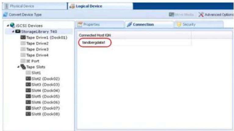
You can also set iSCSI security from the iSCSI Management dialog window. See “Set iSCSI Security” on page 30 for more information.
Move a Media Cartridge
With RDX QuikStation virtual library configurations, you can logically move media to an open slot, to the IE port, or to the tape drives.
NOTE: If you move media to the IE port, the cartridge will be ejected from the dock, and the media is logically removed from the library.
In most cases, you should use your backup software application to logically move media within the virtual library or autoloader. This functionality is built into the RDX QuikStation mainly for testing and diagnostic purposes.
NOTE: Make sure that you do not have any backup jobs in progress before you logically move a cartridge.
To logically move media:
-
From the Logical Device interface, select the tape slot, tape drive, or IE Port from the tree view in the left pane.
-
Select Move Media.

The Move Media dialog window opens.

-
Using the drop-down menus, verify the Source slot and select the Destination slot. The Source drop-down menu only displays the slots that contain an inserted cartridge, and the Destination drop-down menu only displays empty slots.
-
Click Move.
Set the Unique Inquiry Option
The Unique Inquiry option is available from the Advanced Options dialog.
You can set the RDX QuikStation to report the tape library/autoloader unique inquiry string, or an RDX QuikStation inquiry string.
| Inquiry String setting Behavior | |
| Original device inquiry string (Default) | The virtual tape library reports the device's original inquiry string. This is the inquiry string that a physical version of the tape library reports.For example, the device inquiry string for a Tandberg Data StorageLibrary T24 is “Magnum 224” (derived from the library’s former name). |
| RDX QuikStation inquiry string | The virtual tape library reports “RDX QuikStation” as the device inquiry string. This option is mainly used for diagnostic purposes. |
iSCSI Device General Information
You can view general information about a logical device's iSCSI targets from the iSCSI Devices view in the Remote Management Console.
To view iSCSI Devices, under the Logical Device tab, select iSCSI Devices from the tree view in the left pane.

By default, the ISCSI Devices Properties window displays information such as the volume name, serial number (UUID), and iSCSI name for the logical device's iSCSI targets.
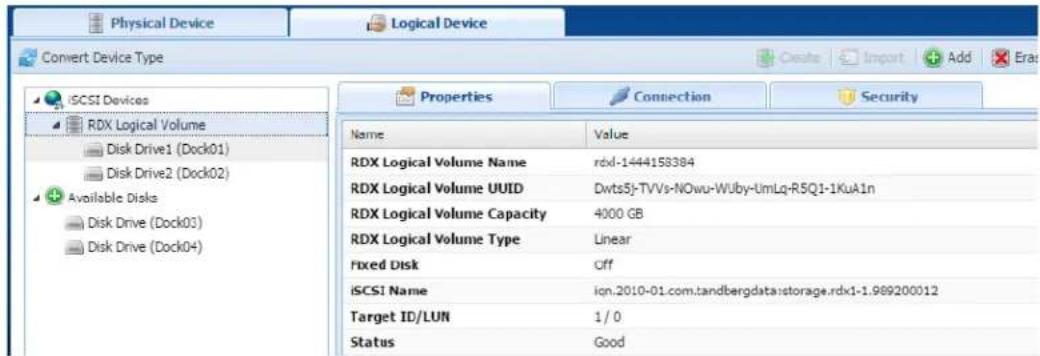
RDX QuikStation RDX Logical Volume logical device properties:
| Property Name Description |
| RDX Logical Volume Name Name of the RDX volume. |
| RDX Logical Volume UUID Unique identification number of the RDX volume. |
| RDX Logical Volume Capacity Total capacity of the logical volume. |
| Fixed Disk Provides a presentation to the iSCSI initiator.Fixed disk shown as either On or Off. |
| iSCSI Name Displays full iSCSI name. |
| Target ID/LUN Shows “1/0”. |
| Status Displays the operating status for the device ofeither good, offline, or an error state. |

RDX QuikStation RDX Drive logical device properties:
| Property Name Description | |
| Vendor Shows the SCSI Inquiry Vendor ID. | |
| Product Displays the SCSI Inquiry Product ID. | |
| Revision Provides the firmware version for RDX dock. | |
| Serial Number Lists the RDX Dock Serial Number. | |
| iSCSI Name | The iSCSI name that identifies the device and is used to connect the initiators (host computers) to the targets. |
| Target ID/LUN Shows “1/0.” | |
| Status Displays the operating status for the device of either offline, or an error state. | good, |
| Fixed Disk Provides a presentation to the iSCSI initiator. Fixed disk shown as either On or Off. | |
| Media Label The default media label is derived from the last eight digits of the RDX cartridge serial number. | |
| Media Statea | The media state displays either loaded or unloaded depending on how the drive is set in your backup application. |
aOnly present if media is present in the dock.
Customize the iSCSI Devices View
You can sort the columns in ascending or descending order and select which columns are visible.
To customize the iSCSI Devices view, select the down arrow (▼) which appears when you move your mouse over the Product or Serial Number column head.
View Active iSCSI Connections for iSCSI Devices
- From the Logical Device interface, select an iSCSI device target from the tree view in the left pane.
NOTE: The Connection tab only displays when you have selected an iSCSI device target from the left pane.

- Select the Connection tab.
If there is a host connected to the target, the host's initiator node name is displayed in the Connection window.

NOTE: You can also set iSCSI security for each iSCSI target. See "Set iSCSI Security" on page 30 for more information.
7
Physical Device Management
This chapter describes the Remote Management Console Physical Device interface.
The physical device view is useful for determining the physical location of your RDX media, since logical library views can differ. You can also use the physical device view to force-eject RDX media, erase RDX media, and clone data from one RDX media to another.
Topics in Setup and Configuration:
• Viewing Physical Device Properties
- Ejecting RDX Media
• Reformatting RDX Media
- Cloning Data
Viewing Physical Device Properties

The following RDX dock properties are displayed when you select an RDX dock in the left pane of the Physical Device interface.
| Property Name Description |
| Dock Version The RDX dock firmware version. |
| Cartridge Status The operating system status for the RDX QuikStation media.The status can either display good or an error state. |
| Cartridge Serial Number Serial number of the RDX media. |
| Cartridge Label By default, the text is derived from the RDX media serial number. |
| Cartridge Capacity Storage size of the RDX media (used and unused). |
| Cartridge Temp (Celsius) The current temperature of the inserted RDX media. |
| Write Protected Displays information on whether the RDX media is write-protected or not. |
Ejecting RDX Media
You can eject an RDX media from the Remote Management Console. However, with removable disk configurations, unless you first enable the Unsafe Eject option (see "Setting Removable Disk Options" on page 56), the request to eject the RDX medium will only be executed if the disk is not connected to an iSCSI host or if the connected host has granted permission to remove the medium.
NOTE: Make sure that you do not have any backup jobs in progress before you eject RDX media from the Remote Management Console.
To eject RDX media:
- From the Physical Device interface, select the dock where the RDX media is located.
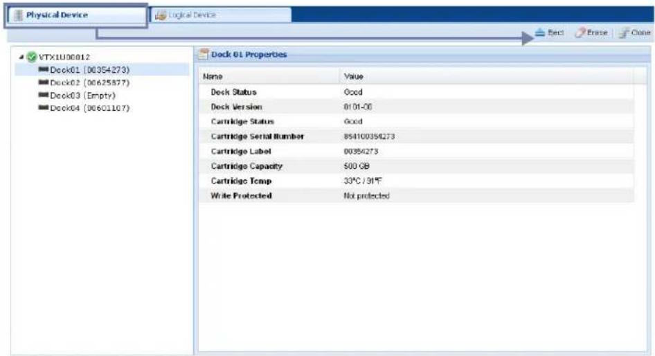
2. Click Eject.
The RDX QuikStation ejects the RDX media. The dock displays "Empty" in the tree view.
If the RDX media selected is part of an active logical volume, the following Warning appears:
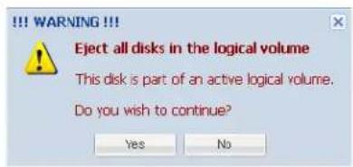

CAUTION: Tandberg Data does not recommend ejecting RDX media that is part of an active logical volume.
Reformatting RDX Media
You can reformat RDX media as a single NTFS partition from the Remote Management Console.
NOTE: You cannot reformat a disk in an RDX disk configuration if the iSCSI target related to that disk is connected to a host. You can also not reformat a disk that is part of an active logical volume.
To erase an RDX media:
- From the Physical Device interface, select the dock where the RDX media is located.
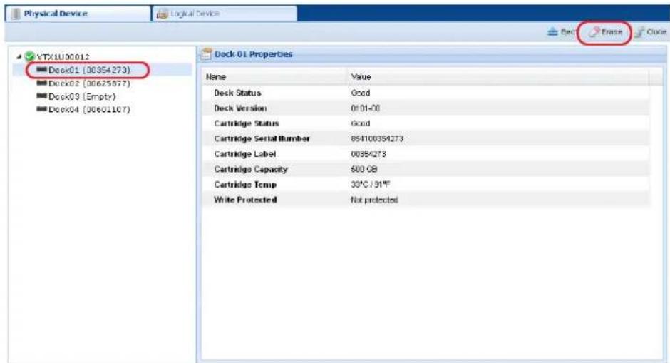
- Click Erase.
- Click Yes to confirm.
Cloning Data
You can copy data from one RDX media to another by using the cloning feature in the Remote Management Console. Disks that are part of an active logical volume may not be used in a cloning operation.

CAUTION: Cloning a 3 TB disk or larger using code that is earlier than v01.002.00 may cause corruption of the destination disk and render it Not Authorized and unusable.
The cloning function copies the source RDX media to a destination media, sector by sector, so that the destination media will be an exact image of the source media.
- Cloning will be rejected if the destination media is smaller than the source media.
- If the destination RDX media is bigger, a part of the destination disk would be unreachable after cloning is finished.
NOTE: Disks partitioned with GPT have a backup copy at the end of the media. Using bigger media will misplace that backup copy and might cause a warning in some OS.
To clone data:
-
Insert both the source and destination RDX media into available docks on the RDX QuikStation.
-
From the Physical Device interface, click Clone.

The Clone dialog window opens.

-
Select the Source RDX media from the drop-down menu.
-
Select the Destination RDX media from the drop-down menu.
NOTE: The iSCSI targets related to the source and destination RDX media will be offline during the cloning process.
5. Click Start.
The RDX QuikStation begins the cloning process. You can monitor the progress of the cloning job in the bottom-right corner of the Physical Device interface.

8
System Maintenance
This chapter describes the RDX QuikStation system maintenance tasks that a user with administrator privileges can perform.
Topics in Setup and Configuration:
• System Maintenance Overview
- Generate System Logs
• RDX QuikStation Restart and Shutdown
- Export RDX QuikStation System Configuration Files
- Import RDX QuikStation System Configuration Files
• Manually Update RDX QuikStation Firmware
- Use a USB Flash Drive for System Tasks
System Maintenance Overview
As a user with administrator permissions, the following functions are available from the System Maintenance menu on the Remote Management Console.
| Menu Name Description |
| System Log Allows you to download system log files to a host computer. These files are encrypted and are meant for Tandberg Data technical support only. |
| System Restart Allows you to restart the RDX QuikStation. Important: Before you restart the system for any reason, make sure there are no active host connections to the iSCSI targets. |
| System Shutdown Allows you to perform a soft shut down of the RDX QuikStation, which is the preferred way to turn off the power to the unit. If you need to do a hard shut down, press and hold the power button on the front of the RDX QuikStation for 10 seconds. Important: Before you shut down the system for any reason, make sure there are no active host connections to the iSCSI targets. |
| Import Configuration Allows you to import RDX QuikStation system configuration files, such as network information, email notification setting, time zone, user names and passwords, logical device type settings, and iSCSI security settings to another RDX QuikStation. |
| Export Configuration Allows you to export RDX QuikStation system configuration settings, such as network information, email notification, time zone, user names and passwords, logical device type settings, and iSCSI security settings.Tandberg Data recommends that you export your system configuration files as a backup in case you ever need to replace your current unit. |
| Update Firmware Allows you to automatically check for updates and manually upload a firmware file.Important: Before you update firmware, make sure there are no active host connections to the iSCSI targets. |
Generate System Logs
There are three levels of system logs that may be generated from the RDX QuikStation: Normal, Detail, and Extend (see “Options for RDX QuikStation” on page 55).
System logs are encrypted and only intended for use by Tandberg Data technical support. You do not need to generate a system log unless you are instructed to do so by Overland-Tandberg technical support. Logs may also be generated automatically if some issue is detected by firmware. You will be asked to save them locally and advised to send them to Overland-Tandberg technical support.
To generate a system log:
- From the Remote Management Console main menu, select System Maintenance > System Log.
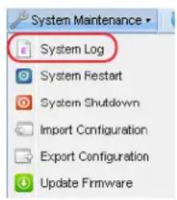
- Save the file to your local host.
NOTE: You can also generate a log dump by inserting an empty USB flash drive (formatted with a VFAT32 or NTFS file system) into the RDX QuikStation. The RDX QuikStation automatically generates a log dump when a USB flash drive is detected. Make sure that the flash drive does not include any RDX QuikStation system configuration files (see "Use a USB Flash Drive for System Tasks" on page 103). Otherwise, the RDX QuikStation will read and process those files instead of generating a system log.
Diagnostics Tab Options
To access the Diagnostics tab:
- From the Remote Management Console main menu, select System Settings > Options.

The Options dialog window opens with the Removable Disk tab selected.
- Select Diagnostics.
The Diagnostics tab is shown.


IMPORTANT: Overland-Tandberg recommends that you change the log level only if you are instructed to do so by Overland-Tandberg Technical Support.
- If directed to do so by Overland-Tandberg Technical Support, use the drop-down menu to change the log level from Normal to either Detail or Extend.
NOTE: If you change the log level, the system will default back to Normal once the Remote Management Console browser session is closed.
RDX QuikStation Restart and Shutdown

CAUTION: Before you restart or shut down the system for any reason, make sure there are no active hosts that are currently communicating with the iSCSI targets.
System Restart
- From the Remote Management Console main menu, select System Maintenance > System Restart.

- Click Yes to confirm.
The system reboots. This process takes three minutes. When the reboot is complete, the Remote Management Console interface is active again. You do not have to sign in again to access the Console.
System Shutdown
- From the Remote Management Console main menu, select System Maintenance > System Shutdown.

- Click Yes to confirm.
If you cannot access the Remote Management Console, verify that your network infrastructure is up and running and you are using a correct IP address. Contact technical support if you need further assistance.
If the Remote Management Console is unavailable, you can initiate an OS shutdown by quickly pressing the power button (less than one second).

CAUTION: If you press and hold power button for more than three (3) seconds, you will immediately cut off the unit's power for a hard power-off without any software shut down. Any non-disconnected iSCSI connection would be terminated. It is strongly advised to avoid using power button as a standard procedure.
Export RDX QuikStation System Configuration Files
As a best practice, Overland-Tandberg recommends that you export your system configuration files as a backup in case you ever need to replace your current unit. The system exports all configuration settings, including network information, email notification settings, time zone setting, user names and passwords, logical device type settings, and iSCSI security settings.
To export RDX QuikStation system configuration files:
- From the Remote Management Console main menu, select System Maintenance > Export Configuration.

The Export Configuration dialog window opens.

-
Click Export to generate the configuration file.
-
Click OK to download the file to your local host. Note the name and location of the downloaded file.
Import RDX QuikStation System Configuration Files
You can only import configuration files generated by an RDX QuikStation. Configuration files from other Overland-Tandberg products are not compatible.
To import system configuration files:
- From the Remote Management Console main menu, select System Maintenance > Import Configuration.
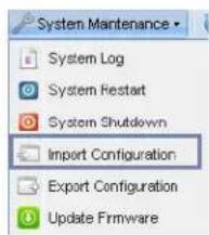
The Import Configuration dialog window opens.
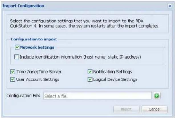
- Select the network settings you want to import.
By default, all configuration settings are selected. - Click the plus (+) icon to select the RDX QuikStation configuration file.
- Click Import.
The system reboots. This process takes three minutes. When the reboot is complete, the Remote Management Console interface is active again. You do not have to sign in again to access the Console.
If the imported file contains different network settings than are currently active, you may have to reopen the browser with the updated RDX QuikStation IP address. Refer to "Obtain the IP Address" on page 17 to determine the current IP address.
Manually Update RDX QuikStation Firmware
If the Check firmware update automatically option is enabled (see "Options for RDX QuikStation" on page 55), when you sign in as an administrator, the RDX QuikStation detects the firmware version. If your system is not running the most current version, the RDX QuikStation prompts you to update the firmware. If you choose to update, the system automatically installs the new firmware version.
Follow these instructions if you need to manually update the firmware file to your system.

CAUTION: Before you update the firmware, make sure there are no active hosts that are currently communicating with the iSCSI targets.
To manually update the RDX QuikStation firmware:
- From the Remote Management Console main menu, select System Maintenance > Update Firmware.

The Update Firmware dialog window opens.

- Select Update the RDX QuikStation n firmware manually.

- Click the Tandberg Data Support website link to access the most current firmware file. After you download the file from the website, make sure you extract the zipped file before uploading it to the RDX QuikStation. The firmware file uses the following format: vtxlu-aa.bb.cc.fw.
- Click the plus (+) icon to select the configuration file. The firmware file must be appropriate for your device, either for QuikStation 4 or for QuikStation 8. These code files are not interchangeable.
- Click Update.
- Click Yes to proceed.
The system reboots. This process takes three minutes. When the reboot is complete, the Remote Management Console interface is active again. You do not have to sign in again to access the Console.
NOTE: You can also update firmware by saving the firmware file to a USB flash drive (formatted with a VFAT32 or NTFS file system). Rename the firmware file vtx1u.fw and insert the flash drive into the RDX QuikStation. The RDX QuikStation automatically detects the firmware and updates the system.
Use a USB Flash Drive for System Tasks
The RDX QuikStation ships with a USB flash drive you can use to perform many system tasks. If the RDX QuikStation flash drive is unavailable, you can use any USB flash drive that is formatted with a VFAT32 or NTFS file system.
NOTE: The Tandberg Data-supplied USB flash drive might include configuration example files. Change file extensions to *.example to make sure the correct action would be performed by RDX QuikStation firmware.
The following table describes the system tasks you can complete using a USB flash drive.
| System Task Description |
| Network information You can get current active network settings by creating an empty file named network.info on USB stick.When the flash drive is inserted into the RDX QuikStation, the system automatically writes detailed network information into that text file. Any existing content in that file is erased prior to writing network settings. |
| Network configuration You can configure network settings for the RDX QuikStation via the network.conf file, which is included on your RDX QuikStation USB flash drive. When the flash drive is inserted into the RDX QuikStation, the system automatically detects and imports the network settings from the file. For more information, see “Options for RDX QuikStation” on page 55.Important: The file must be named network.conf in order for the RDX QuikStation to import network settings. |
| Firmware updates You can update firmware by saving the firmware file to a USB flash drive and inserting the flash drive into the RDX QuikStation. The RDX QuikStation automatically detects the firmware and updates the system. For more information, see “Manually Update RDX QuikStation Firmware” on page 102.Important: Rename the firmware file vtx1u.fw so that the RDX QuikStation can detect and load the file. |
| Password recovery You can reset the built-in administrator password via USB by creating an empty password.reset file. For more information, see “Recovering the Built-In Administrator Password” on page 50. |
| System log dump You can generate a log dump by inserting a USB flash drive into the RDX QuikStation. The RDX QuikStation automatically generates a system log when a USB flash drive is detected. For more information, see “Generate System Logs” on page 98.Important: If any of the following files - network.conf, password.reset, network.info or vtx1u.fw - are loaded onto the flash drive, the RDX QuikStation will not generate a log dump, but will instead read and load the file. |
This appendix provides information on error codes and some basic troubleshooting questions and solutions.
For more detailed troubleshooting help, visit the Support section of the Tandberg Data website (www.tandbergdata.com), or contact Overland-Tandberg technical support.
Basic Troubleshooting Information
The following table describes some basic troubleshooting information. If you have a problem that is not addressed in the table below, contact Overland-Tandberg technical support.
| Problem Potential Solutions | |
| Can’t connect to an iSCSI target. | Check to see if another host is already connected to the target (see “View Active iSCSI Connections for iSCSI Devices” on page 90). In many cases, the RDX QuikStation allows only one active host connection per iSCSI target (see “iSCSI Configuration Overview” on page 22).Check if any iSCSI security is enabled for the target (see “Setting iSCSI Security in the Remote Management Console” on page 31).If the target uses CHAP authentication, make sure the CHAP secret specified in the Remote Management Console (see “Enabling CHAP Authentication” on page 31) matches the CHAP secret specified in your iSCSI initiator software.Refresh the discovered targets in your iSCSI initiator software. This may require restarting the iSCSI initiator. |
| The Remote Management Console has a “session timeout” error message. | The Remote Management Console times out after 30 minutes of inactivity.Click OK to return to the console sign-in page. Type your user name and password to re-connect to the Remote Management Console. |
| RDX dock reports as “empty” in the Remote Management Console when an RDX media is loaded in the dock. | The RDX media may not be seated properly in the dock. Push the RDX media into the dock until you hear it click in place. If this does not work, try re-seating the RDX media by ejecting it and then re-inserting it. |
| Test email notification is unsuccessful. | If the network is set to a static IP address, make sure that the Default Gateway, Search Domain, and Primary DNS are set correctly so that the email server may be accessed. |
| Can’t access the Remote Management Console. | Verify that your network is operating properly.Verify that you are using a correct IP address. |
This appendix provides the information about the RDX QuikStation specifications.
Topics in Setup and Configuration:
• Physical Specifications
• Power Specifications
• Environmental Specifications
• Safety and Regulatory Agency Compliance
Physical Specifications
The following tables give the physical specifications for the three different RDX models.
QuikStation 4 Desktop Appliance
| Part Number 8922-RDX | |
| Dimensions (D x W x H) 48.1cm x 44.0cm x 6.8cm / 18.9in. x 17.3in. x 2.7in. | |
| Weight 9.78 kilograms / 21.6 pounds | |
| Form Factor Desktop | |
| Capacity RDX media dependent (online): 4 x 4TB RDX media. | * |
| NOTE: For media greater than 2.2TB, the firmware must be version 3.001.03 or higher. | |
| Unlimited offline capacity. | |
| Data Transfer Rate Up to 200 MB †/second across multiple docks (write, uncompressed). See “Port Configuration Options” on page 44. | |
| Network Connectivity 2 x 1 Gigabit Ethernet | |
| USB 2.0 Ports 6 on rear panel | |
| USB 3.0 Ports 1 on front panel, 2 on rear panel | |
| Removable Media Drive 4 x RDX bays | |
| RDX Media Compatibility (Capacity) | Backward and forward to all RDX media of all capacities |
* 4TB cartridge is the largest size available when this product was published; however, the online capacity is only limited by the size of the RDX cartridge available. Please refer to TandbergData.com for current maximum capacity cartridges.
† The data transfer rate is up to 200 MB/second when port configuration is configured for adaptive load balancing or dynamic link aggregation.
QuikStation 4 Rack-mount Appliance
| Part Number 8920-RDX | |
| Dimensions (D x W x H) 47.8cm x 44.0cm x 4.3cm / 18.8in. x 17.3in. x 1.7in. | |
| Weight 6.02 kilograms / 13.3 pounds | |
| Form Factor 1U rackmount | |
| Capacity RDX media dependent (online): 4 x 4TB RDX media. | * |
| NOTE: For media greater than 2.2TB, the firmware must be version 3.001.03 or higher. | |
| Unlimited offline capacity. | |
| Data Transfer Rate Up to 200 MB †/second across multiple docks (write, uncompressed). See “Port Configuration Options” on page 44. | |
| Network Connectivity 2 x 1 Gigabit Ethernet | |
| USB 2.0 Ports 6 on rear panel | |
| USB 3.0 Ports 1 on front panel, 2 on rear panel | |
| Removable Media Drive 4 x RDX bays | |
| RDX Media Compatibility (Capacity) | Backward and forward to all RDX media of all capacities |
* 4TB cartridge is the largest size available when this product was published; however, the online capacity is only limited by the size of the RDX cartridge available. Please refer to TandbergData.com for current maximum capacity cartridges.
† The data transfer rate is up to 200 MB/second when port configuration is configured for adaptive load balancing or dynamic link aggregation.
QuikStation 8 Rack-mount Appliance
| Part Number 8930-RDX | |
| 8940-RDX | |
| Dimensions (D x W x H) 47.8cm x 44.0cm x 8.6cm / 18.8in. x 17.3in. x 3.4in. | |
| Weight 14.96 kilograms / 33.3 pounds | |
| Form Factor 2U rackmount | |
| Capacity RDX media dependent (online): 8 x 4TB RDX media. | * |
| NOTE: For media greater than 2.2TB, the firmware must be version 3.001.03 or higher. | |
| Unlimited offline capacity. | |
| Data Transfer Rate Up to 1000 MB/second across multiple docks (write, uncompressed). See “Port Configuration Options” on page 44. | |
| Network Connectivity 4 x 1 Gigabit Ethernet | |
| 1 x 1 10Gigabit Ethernet (optional) | |
| USB 2.0 Ports 1 on front panel, 2 on rear panel | |
| USB 3.0 Ports 2 on rear panel | |
| Removable Media Drive 8 x RDX bays | |
| RDX Media Compatibility (Capacity) | Backward and forward to all RDX media of all capacities |
* 4TB cartridge is the largest size available when this product was published; however, the online capacity is only limited by the size of the RDX cartridge available. Please refer to TandbergData.com for current maximum capacity cartridges.
Power Specifications
AC Input Voltage 100-240 VAC
Rated Input Current 2,0 -1,0 A
Rated Input Frequency 50/60 Hz
Power Consumption <90 Watts, typical
Environmental Specifications
Operating Temperature 0° to 40° C (50° to 104° F)
Non-operating Temperature -20° to 60° C (-4° to 140° F)
Operating Humidity 20% to 80%
Safety and Regulatory Agency Compliance
Tandberg Data products are designed, tested, and classified for their intended electromagnetic environment. The RDX QuikStation is a Class A device and complies with the safety and regulatory agency standards listed below when installed in accordance with this manual.
For regulatory purposes, the RDX QuikStation 4 regulatory model number is filed as RMN-A-01-14 and the QuikStation 8 regulatory model number is filed as RMN-A-01-16.

The cTUVus mark for both the RDX QuikStation 4 and 8 demonstrates that they have met the requirements of UL60950-1,2nd Ed.

The TUV Tested Safety mark for the RDX QuikStation 4 demonstrates that it has met the quality and safety requirements set forth in the German Product Safety Act.
European Community

This Information Technology Equipment has been tested and found to comply with the following European directives:
(1) EMC Directive 2014/30/EU of 26 February 2014
(2) LVD Directive to 2014/35/EU of 26 February 2014
(3) RoHS Directive 2011/65/EU of 8 June 2011
EN 55022: 2006 + AC: 2011, Class A
EN 61000-3-2: 2006 +A1:2009 +A2:2009
EN 61000-3-3: 2008
EN 61000-6-3: 2007 +A1: 2011
EN 55024: 2010
EN 61000-6-2: 2005
EN 60950-1: A2:2013
EN 62479: 2010
EN 50581: 2012
Waste of Electronic and Electrical Equipment (WEEE)

This device is in compliance with 2002\96\EC Waste of Electronic and Electrical Equipment (WEEE).

Australia and New Zealand

This device has been tested and found to comply with the limits for a Class A digital device, pursuant to the Australian/New Zealand standard AS/NZS CISPR22 : 2009 for Information Technology Equipment and EN 55022 : 2010 + AC:2011 - Limits and Methods of Radio Disturbance Characteristics of Information Technology Equipment set out by the Australian Communications Agency.
China RoHS

This product is marked in accordance with China's Ministry of Information Industry (MII) “Management Methods for Controlling Pollution Cause by Electronic Information Products” Order #39. The Environmental Protection Use Period (EPUP) is determined to be 10 years. Packaging materials are also marked according to Chinese national standard GB 18455 - 2001 “Packaging and Recycling Symbols”.
Japan

Translation: This is a Class A product based on the standard of the Voluntary Control Council for Interference by Information Technology Equipment (VCCI). If this equipment is used in a domestic environment, radio disturbance may arise. When such trouble occurs, the user may be required to take corrective actions.
Korea

natural_image
Abstract geometric logo design with stylized letter K and curved lines (no text or symbols)This product is marked in accordance with Korea's Registration of Broadcasting and Communication Equipments. It is verified that foregoing equipment has been registered under the Clause 3, Article 58-2 of Radio Waves Act.
United States: FCC Declaration of Conformity

We declare under our sole responsibility that:
Product Name: RDX QuikStation, regulatory model RMN-A-01-16
To which this declaration relates, is in conformity with the following standard(s) or other normative documents:
• ANSI C63.4-2009 Methods of Measurement
• Federal Communications Commission 47 CFR Part 15, Subpart A/B, Class B: 2013
This equipment has been tested and found to comply with the limits for a Class AB digital device, pursuant to Part 15 of the FCC Rules. These limits are designed to provide reasonable protection against harmful interference when the equipment is operated in a commercial environment. This equipment generates, uses, and can radiate radio frequency energy and, if not installed and used in accordance with this manual, may cause harmful interference to radio communications.
Operation of this equipment in a residential area is likely to cause harmful interference in which case the user will be required to correct the interference at his own expense.
This appendix provides safety guidelines for the RDX QuikStation.
Topics in Setup and Configuration:
- General Safety Precautions
• Electrical Safety Precautions - ESD Precautions
General Safety Precautions
- Keep the area around the RDX QuikStation clean and free of clutter.
- Remove any jewelry or metal objects from your body, which are excellent metal conductors that can create short circuits and harm you if they come in contact with printed circuit boards or areas where power is present.
- Elevated Operating Ambient - If installed in a closed or multi-unit rack assembly, the operating ambient temperature of the rack environment may be greater than room ambient. Therefore, consideration should be given to installing the equipment in an environment compatible with the maximum ambient temperature (Tmax) specified by the manufacturer (40° C / 104° F).
- Reduced Air Flow - Installation of the equipment in a rack should be such that the amount of air flow required for safe operation of the equipment is not compromised.
- Mechanical Loading - Mounting of the equipment in the rack should be such that a hazardous condition is not achieved due to uneven mechanical loading.
- Circuit Overloading - Consideration should be given to the connection of the equipment to the supply circuit and the effect that overloading of the circuits might have on overcurrent protection and supply wiring. Appropriate consideration of equipment nameplate ratings should be used when addressing this concern.
- Reliable Earthing - Reliable earthing of rack-mounted equipment should be maintained. Particular attention should be given to supply connections other than direct connections to the branch circuit (for example, use of power strips).
- Never place objects on top of rack-mounted equipment.
Electrical Safety Precautions
- Be aware of the locations of the ON/OFF switch on the chassis as well as the room's emergency power-off switch, disconnection switch, or electrical outlets. The ON/OFF switch does not disconnect power to the chassis. If an electrical accident occurs, quickly remove power to the system by removing the plugs from the outlets. Some models may have multiple power cords which connect to more than one outlet.
- The power cord must include a grounded plug and must be plugged into a grounded electrical outlet.
- Use only one hand when working with powered-on electrical equipment. This is to avoid making a complete circuit, which will cause electrical shock. Use extreme caution when using metal tools, which can easily damage electrical components or circuit boards they come into contact with.
ESD Precautions
Electrostatic discharge (ESD) is generated by two objects with different electrical charges coming into contact with each other. An electrical discharge is created to neutralize this difference, which can damage electronic components and printed circuit boards. The following measures are generally sufficient to neutralize this difference before contact is made to protect your equipment from ESD.
- Use a grounded wrist strap designed to prevent static discharge.
- Discharge static electricity from your body by touching a known grounded surface, such as a computer's metal chassis.
- Keep all components and printed circuit boards (PCBs) in their anti-static bags until ready for use.
- For grounding purposes, make sure your computer chassis provides excellent conductivity between the power supply, the case, the mounting fasteners, and the printed circuit boards.
Index
Symbols
(menu flow indicator) 5
A
active-backup/failover network mode 44
adaptive load balancing network mode 45
administrator group
adding to 48
editing 49
permissions 47
removing users from 49
administrator password, recovering 50
agency compliance 109
agency declarations
Japan 111
alert definitions 4
authentication
best practice for setting security 30
CHAP 30
hosts 30
C
CHAP 30
enabling in the Remote Management Console 31
Microsoft iSCSI initiator 33
Open-iSCSI for Linux 34
secret/password requirements 32
Xtend SAN initiator for Mac OS X 35
cloning data 94
configuration files
exporting 101
importing 101
configuring network settings 40
conventions, typographical 4
D
date and time setting 39
diagnostic
system logs 98
dynamic link aggregation network mode 45
E
eject button/power LED indicators 13, 14
electrical safety precautions 112
electrostatic discharge (ESD) precautions 113
email notification 45
customizing 47
environmental specifications 109
erasing RDX cartridges 94
establishing iSCSI connections 22
exporting system configuration files 101
F
failover network mode 44
fault tolerance 70
firmware
updating manually 102
formatting RDX cartridges 94
G
general safety precautions 112
groups
adding users 48
editing user information 49
permissions 47
removing users from 49
H
host authentication
enabling in the Remote Management Console 32
overview 30
I
importing system configuration files 101
initiator 22
IP address
obtaining 17
static 18
iSCSI
best practice for setting security 30
configuration overview 22
connecting iSCSI targets for Linux 26
connecting iSCSI targets for Linux with CHAP 34
connecting iSCSI targets for Mac OS X 27
connecting iSCSI targets for Mac OS X with CHAP 35
connecting iSCSI targets for Windows 23
connecting iSCSI targets for Windows with CHAP 33
enabling CHAP in the Remote Management Console 31
enabling host authentication in the Remote
Management Console 32
security overview 30
iSCSI initiator 22
iSCSI target 22
L
Linux
command to delete a target 27
command to disconnect a target 27
connecting iSCSI targets 26
connecting targets with CHAP 34
log files, generating 98
log level, changing 55
logical device type
configuring 20
M
Mac OS X
connecting iSCSI targets 27
connecting targets with CHAP 35
maintenance tasks 97
manager group
adding to 48
editing 49
permissions 47
removing users from 49
menu flow indicator 5
Microsoft iSCSI initiator
connecting with CHAP 33
connecting without CHAP 23
N
network
configuring RDX QuikStation 40
port bonding options 44
0
Open-iSCSI for Linux
command to delete a target 27
command to disconnect a target 27
connecting with CHAP 34
connecting without authentication 26
P
password.reset file, creating 52
passwords
recovering for the built-in Admin account 50
requirements for CHAP 32
requirements for user groups 48
resetting Admin password via USB 52
permissions for groups in Remote Management Console 47
physical specifications 107
port bonding modes 44
power ratings 109
product documentation 4
R
RDX cartridge
cloning data 94
eject button/power LED indicators 13, 14
enabling unsafe eject 56
erasing/formatting 94
RDX QuikStation
configuring network information 40
exporting configuration files 101
generating system logs 98
importing configuration files 101
physical specifications 107
power ratings 109
restarting 100
safety guidelines 112
shutting down 100
system components 12, 14
system maintenance overview 97
System Settings 38
updating firmware 102
regulatory agency compliance 109
Remote Management Console
adding users to a group 48
configuring logical device type 20
configuring network information 40
editing user information 49
group permissions 47
iSCSI security overview 30
removing users 49
setting iSCSI security 31
system maintenance overview 97
System Settings overview 38
removable disk
unsafe eject mode 56
restarting the RDX QuikStation 100
S
safety guidelines
electrical precautions 112
ESD precautions 113
security
enabling CHAP in the Remote Management
Console 31
specifying hosts in the Remote Management
Console 32
shutting down the RDX QuikStation 100
specifications
physical 107
power 109
power ratings 109
SSH (Secure Shell) remote access option 55
static IP address 18
system components 12, 14
system maintenance
exporting configuration files 101
generating system logs 98
importing configuration files 101
overview 97
restarting the RDX QuikStation 100
shutting down the RDX QuikStation 100
updating firmware 102
System Settings
adding users to a group 48
date/time 39
editing user groups 49
email notification 45
enable SSH remote access 55
group permissions 47
log level 55
network configuration 40
overview 38
port bonding options 44
removing users 49
unsafe eject option 56
T
target 22
time setting, modifying 39
troubleshooting
system logs 98
typographical conventions 4
U
Unsafe Eject Button Option 57
unsafe eject option 56
updating firmware 102
USB flash drive
generating system logs 98
resetting the administrator password 52
updating firmware 102
uses for 103
user group
adding to 48
editing 49
permissions 47
removing users from 49
W
Windows
connecting iSCSI targets 23
connecting targets with CHAP 33
X
Xtend SAN iSCSI initiator for Mac OS X
connecting with CHAP 35
connecting without authentication 27

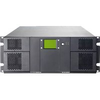
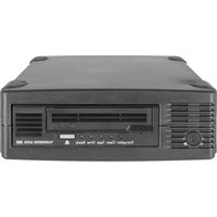


- ©2017 Overland Storage, Inc. All rights reserved.
- PROPRIETARY NOTICE
- REVISION HISTORY
- Preface
- Audience and Purpose
- Organization
- Overview
- Installation and Setup
- Using the RDX Remote Management Console
- Supplemental Information
- Product Documentation & Software Updates
- Technical Support
- Conventions
- Contents
- Chapter 1: Product Overview
- Chapter 2: Initial Setup and Configuration
- Chapter 3: iSCSI Configuration
- Chapter 4: System Configuration
- Chapter 5: Logical Device Management
- Chapter 6: Manage Tape Library Configurations
- Chapter 7: Physical Device Management
- Chapter 8: System Maintenance
- Appendix A: Troubleshooting
- Appendix B: Specifications
- Appendix C: Safety Guidelines
- Index
- 1
- Product Overview
- QuikStation 4 Rack Mount
- QuikStation 4 Desktop
- QuikStation 8 Rack Mount
- Topics in Product Overview:
- RDX QuikStation Features
- Configuration Flexibility
- RDX QuikStation 4
- RDX QuikStation 8
- Tandberg Data RDX Removable Disk Technology
- High Performance and Capacity
- Compatible with Major Backup Software
- Integrated Web-based Management
- Multi-Gigabit Ethernet
- Compact Design
- RDX QuikStation 4 Components
- RDX Media-Eject Button/Status LED
- Rear Components
- RDX QuikStation 8 Components
- # Description
- RDX Dock Media-Eject button Status LED
- LED Status
- QuikStation 8 Front Panel LED
- 2
- Initial Setup and Configuration
- Topics in Setup and Configuration:
- Obtain the IP Address
- Assign a Static IP Address
- Automatically Assigning a DHCP IP Address
- Connect to Remote Management Console
- Configuring the RDX QuikStation
- Setting the Language
- System Settings
- 3
- iSCSI Configuration
- Topics in iSCSI Configuration:
- iSCSI Configuration Overview
- Connecting to iSCSI Targets Without Authentication
- Connecting iSCSI Targets for Windows
- Click the Targets tab.
- For each iSCSI target, complete the following steps:
- Connecting iSCSI Targets for Linux
- Install Open-iSCSI Initiator.
- Discover iSCSI targets.
- Connect iSCSI targets.
- iscsiadm -m node -L all
- iscsiadm -m node -T -p --login
- Other "iscsiadm" Commands
- Connecting iSCSI Targets for Mac OS X
- Highlight all the discovered targets and click Add.
- For each iSCSI target, complete the following steps to connect the target:
- d. Select the Network Node listed and click LogIn.
- Set iSCSI Security
- Setting iSCSI Security in the Remote Management Console
- Enabling CHAP Authentication
- Enabling Host Authentication
- Connecting iSCSI Targets with CHAP for Windows
- Connecting iSCSI Targets with CHAP for Linux
- Connecting iSCSI Targets with CHAP for Mac OS X
- 4
- System Configuration
- System Settings Overview
- Date and Time Configuration
- Network Configuration
- Port Configuration Options
- Bonded Network Configuration
- Split Network Configuration
- Notification Configuration
- Setting Basic Email Notification
- Setting SMTP Authentication
- Customizing Email Subject and From Address
- User Management
- Group Permissions Overview
- Adding Users to a Group
- Removing Users from a Group
- Editing User Information
- Editing the User Name, Group, or Description
- Editing a Password
- Recovering the Built-In Administrator Password
- Resetting the Password via Email
- Resetting the Password via USB
- Convert Device Type
- Options for RDX QuikStation
- Setting Removable Disk Options
- Setting the Auto-Insert Option
- Auto-Insert Option ON
- Auto-Insert Option OFF
- Change Auto-Insert Option
- 5
- Logical Device Management
- Logical Device Type Overview
- Select the Logical Device Type
- RDX Targets
- RDX Individual Dock Drives
- RDX Logical Volume
- RDX Fixed Logical Volume
- RDX Removable Logical Volume
- Logical Volumes
- Creating a Logical Volume
- Importing a Logical Volume
- Expanding a Logical Volume
- Erasing a Logical Volume
- Exporting the Logical Volume
- Protected Volumes
- RDX Protected Volume
- RDX Fixed Protected Volume
- RDX Removable Protected Volume
- Creating a Protected Volume
- From the Logical Device tab, select an available disk
- Click Create to open the Create a Protected Volume Array dialog.
- Select the docks to use in the protected volume, and click Create.
- Importing a Protected Volume
- Expanding a Protected Volume
- Expanding a Fixed Logical Volume File System for a Window Host
- Open the Disk Management tool.
- Expanding a Removable Logical Volume File for a Windows Host
- Erasing a Protected Volume
- Exporting the Protected Volume
- Recovering a Degraded Protected Volume
- Disk Autoloader
- View Logical Properties for Autoloaders
- View Active iSCSI Connections Autoloaders
- Move a Media Cartridge
- Set the Autoloader Option
- 6
- Manage Tape Library Configurations
- View Logical Properties for Tape Libraries
- View Active iSCSI Connections for Tape Libraries
- Set the Unique Inquiry Option
- iSCSI Device General Information
- Customize the iSCSI Devices View
- View Active iSCSI Connections for iSCSI Devices
- 7
- Physical Device Management
- Viewing Physical Device Properties
- Ejecting RDX Media
- Click Eject.
- Reformatting RDX Media
- Cloning Data
- Click Start.
- 8
- System Maintenance
- System Maintenance Overview
- Generate System Logs
- Diagnostics Tab Options
- RDX QuikStation Restart and Shutdown
- System Restart
- System Shutdown
- Export RDX QuikStation System Configuration Files
- Import RDX QuikStation System Configuration Files
- Manually Update RDX QuikStation Firmware
- Use a USB Flash Drive for System Tasks
- Basic Troubleshooting Information
- Physical Specifications
- Power Specifications
- Environmental Specifications
- Safety and Regulatory Agency Compliance
- European Community
- Waste of Electronic and Electrical Equipment (WEEE)
- Australia and New Zealand
- China RoHS
- Japan
- Korea
- United States: FCC Declaration of Conformity
- General Safety Precautions
- Electrical Safety Precautions
- ESD Precautions
- Symbols
- A
- C
- D
- E
- F
- G
- H
- I
- L
- M
- N
- 0
- P
- R
- S
- T
- U
- W
- X
Brand : Tandberg Data
Model : RDX QuikStation 4
Category : Disk array