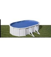
KITPROV613 - Above ground pool GRE - Free user manual and instructions
Find the device manual for free KITPROV613 GRE in PDF.


| Product Type | Above Ground Pool Kit |
| Brand | GRE |
| Model | KITPROV613 |
| Shape | Round |
| Diameter | 12 ft (3.66 m) |
| Height | 30 in (76 cm) |
| Water Capacity | Approx. 1,500 gallons (5,678 L) |
| Frame Material | Rust-resistant galvanized steel |
| Liner Material | PVC with polyester reinforcement |
| Pump Included | Yes, 0.5 HP cartridge filter pump |
| Filter Type | Cartridge filter |
| Flow Rate | Approx. 1,000 gal/h (3,785 L/h) |
| Ladder Included | Yes, A-frame safety ladder |
| Cover Included | Yes, winter cover |
| Ground Cloth Included | Yes |
| Assembly Time | Approx. 1-2 hours |
| Recommended Surface | Level ground |
| Weight | Approx. 150 lbs (68 kg) |
| Power Supply | 110-120 V, GFCI protected outlet |
| Safety Compliance | ASTM F2388 |
| Warranty | 1 year limited |
| User Manual Included | Yes, 32 pages |
Frequently Asked Questions - KITPROV613 GRE
User questions about KITPROV613 GRE
0 question about this device. Answer the ones you know or ask your own.
Ask a new question about this device
Download the instructions for your Above ground pool in PDF format for free! Find your manual KITPROV613 - GRE and take your electronic device back in hand. On this page are published all the documents necessary for the use of your device. KITPROV613 by GRE.
USER MANUAL KITPROV613 GRE
natural_image
Line drawing of an octagonal stone structure with vertical supports and horizontal beams (no text or symbols)Steel wall swimming pool.

Before starting with the assembly, read carefully the instruction manuals of every components of the kit. Keep this instructions for future reference.
Installation video on our website.
Non-contractual photos and pictures.
1 03 - 04
Safety precautions.
2 05 - 07
Preparation of the site.
3 08 - 13
Components.
4 14 - 27
Installation.
5 28 - 29 #6 30
Maintenance and use.
Accessories.
31
Guarantee.
Save this page for future claims and / or returns
#1
Safety precautions.

Safety precautions.
Carefully read, understand, and follow all information in this user manual before installing and using the swimming pool. These warnings, instructions, and safety guidelines address some common risks of water recreation, but they cannot cover all risks and dangers in all cases.
Always use caution, common sense, and good judgment when enjoying any water activity. Retain this information for future use.
Non swimmers safety
Continuous, active, and vigilant supervision of weak swimmers and non-swimmers by a competent adult is required at all times (remembering that children under five are at the highest risk of drowning).
→ Designate a competent adult to supervise the pool each time it is being used.
→ Weak swimmers or non-swimmers should wear personal protection equipment when using the pool.
→ When the pool is not in use, or unsupervised, remove all toys from the swimming pool and its surrounding to avoid attracting children to the pool.
Safety devices
→ It is recommended to install a barrier (and secure all doors and windows, where applicable) to prevent unauthorized access to the swimming pool.
→ Barriers, pool covers, pool alarms, or similar safety devices are helpful aids, but they are not substitutes for continuous and competent adult supervision.
Safety equipment
→ It is recommended to keep rescue equipment (e.g. a ring buoy) by the pool.
→ Keep a working phone and a list of emergency phone numbers near the pool.
Safe use of the pool
→ Encourage all users especially children to learn how to swim
→ Learn Basic Life Support (Cardiopulmonary Resuscitation - CPR) and refresh this knowledge regularly.
This can make a life-saving difference in the event of an emergency:
→ Instruct all pool users, including children, what to do in case of an emergency
→ Never dive into any shallow body of water. This can lead to serious injury or death.
→ Do not use the swimming pool when using alcohol or medication that may impair your ability to safely use the pool.
→ When pool covers are used, remove them completely from the water surface before entering the pool.
→ Protect pool occupants from water related illnesses by keeping the pool water treated and practicing good hygiene. Consult the water treatment guidelines in the user's manual.
→ Store chemicals (e.g. water treatment, cleaning or disinfection products) out of the reach of children.
→ Signage is to be displayed in a prominent position within 2 m of the pool.
→ Removable ladders shall be placed on a horizontal surface.

WARNING
Every electrical appliance fed in 220 V, has to be located at least at 3,50 m from the edge of the pool.
The equipment should be connected to a voltage, with earth connection, protected by a residual current device (RCD) having a rated residual operating current not exceeding 30 mA.
Read the instructions carefully and keep for future reference.
IF YOU HAVE ANY PROBLEM, CONTACT US! www.grepool.com/en/after-sales







#2
Preparation of the site.

Installation site
Our pools are designed to be installed directly on the ground and for outdoor family use. The ground must be firm, smooth, and perfectly flat.
Do not forget: 1000 l. = 1 m ^3 = 1000 Kgs.
Recommendations for choosing the best location for your pool
→ Choose a place where you will have to dig as little as possible to level the ground.
→ An area where in the event of rain, flooding will not occur.
→ Where there are no underground connections (water, gas, electricity, ...).
→ Do not install under power lines.
→ Protected from the wind and free from trees since the pollen and leaves can make the pool water dirty.
→ A sunny area, where there is most sun in the morning.
→ Near an electricity outlet, water outlet, and drainage.
NEVER DO THE INSTALLATION ON: sloping, uneven, loose, or sandy ground with stones.


2.1

Required surface
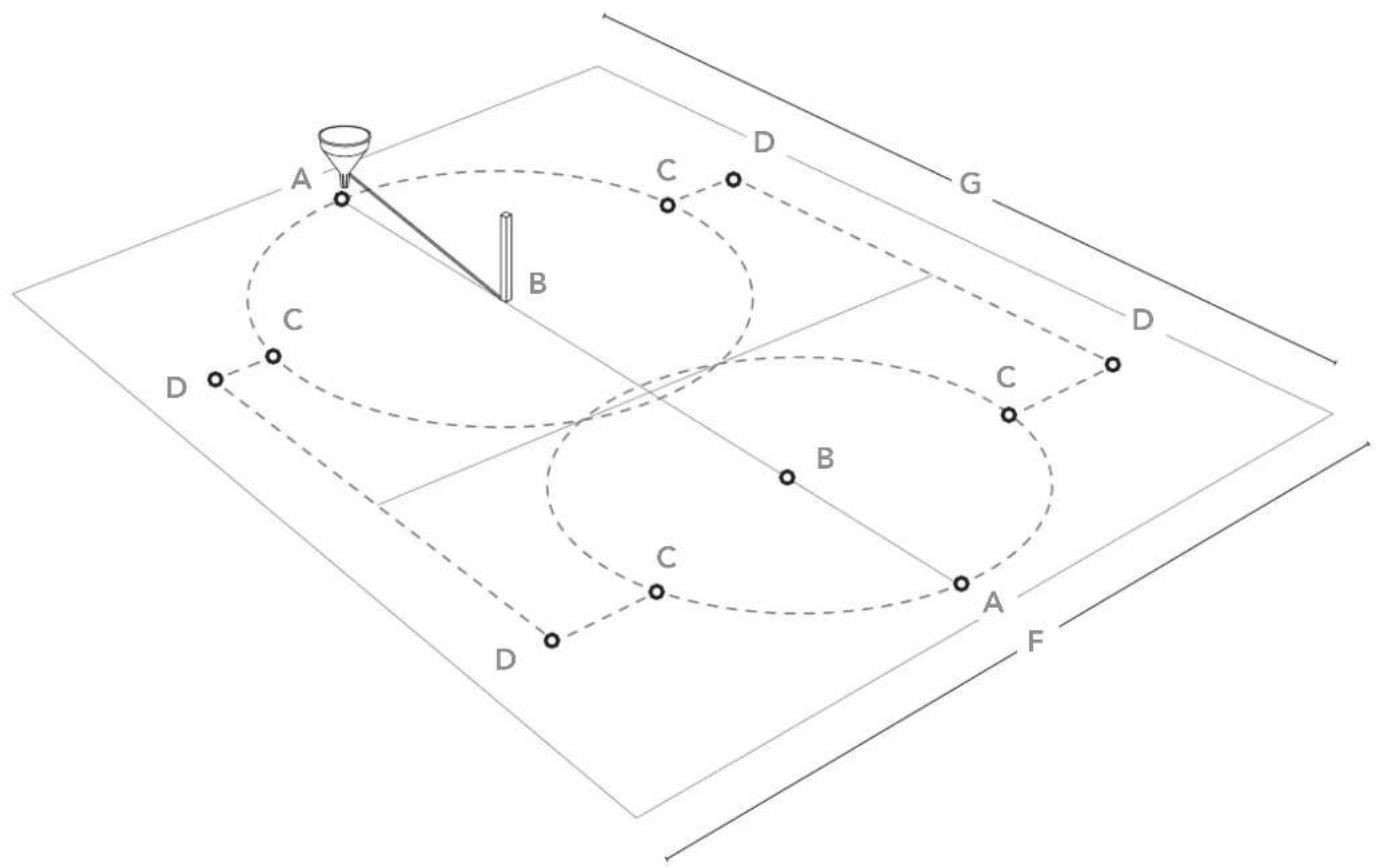
Mark the installation area:
Once the location area is chosen (which have to be perfectly levelled), we'll proceed at the marking.
You've got 2 options for that:
→ 1° To prepare a concrete platform (cement,...) with the necessary measure according to your swimming-pool size.
→ 2° Directly on the ground: To mark the ground using wood pickets, screwdriver, funnel (or plastic bottle), flour or lime and a rope.
It is advisable to level the total surface area necessary before marking it (marking should be centered on the rectangle corresponding to the pool model) so that assembly work is more convenient and easy.
A-A A-B=B-C C-D D-D
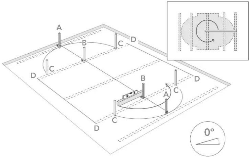
Levelling:
When levelling the ground, always remove material from the top of the slope rather than filling in the bottom: this will ensure greater ground stability and firmness. Always remove all grass, roots, stones, etc. Levelling is extremely important: devoting the necessary time and effort to ensuring that your pool sits properly on the ground will avoid problems later.
How to level: thanks to a large mason rule (aluminium or wood) and a level, level out the ground forming rectangles (or squares), locating this rule in the selected and cleaned area. When all the areas are on level and when the excess of ground is removed, you may fill in the small areas which are left to level out (with clean ground or sand) but always compacting and levelling again afterwards. It is very important the installation area is well compressed and firm in order the ground do not subside when the pool will be full of water. Please ask a professional: builder, gardener,...
2.3

natural_image
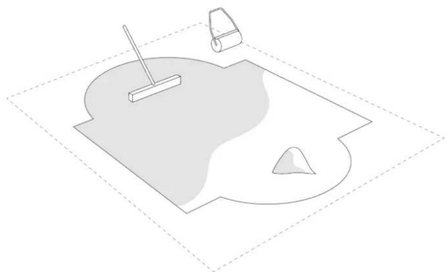
Simple line drawing of a pool with a stick, a small container, and a triangular base (no text or symbols)Finishing:
On the cleaned and levelled ground, spread a light coat of sieved sand (max. 1cm).
Water and compact it (with a garden roller). Check that is well levelled.
Do not use the sand to level the ground. The finishing has to be perfect.
#3
Components.
Draw and classify all components included before assembly.
It's time to assemble the ladder and the pump, follow the respective instructions. Kits with missing parts will be covered by the warranty only if reported to the after-sales service within 15 days as from the date of purchase of the swimming pool.
In order to avoid any possible injury all swimming pool walking entrance must be regularly checked.
Picture 1

Picture 2

Important.
Please, pay attention to the joint protectors coming with your pool when you take out and classify its components:
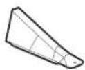
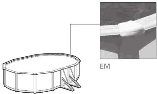
→ If your pool comes with EM (ZC+ZR) joint protectors (see picture 1), you can find your pool parts list on pages 10 and 11.
→ If your pool comes with TPL&TP joint protectors (see picture 2), you can find your pool parts list on pages 12 and 13.
Components.


PLY ZR PLY ZC
PLAYA
PLY
Y = 540 mm
S = 705 mm
I = 1145 mm
X = 820 mm
L = 1330 mm
M = 1095 mm
Q = 1370 mm

EM1
PBL
EM2
PEBASEL

KITPIOBLICUO
PSP
KITPSPPSO

PSO
KITPSPPSO


120 cm
| [000M] | 10,00x5,50 m | 9,15x4,70 m | 8,00x4,70 m | 7,30x3,75 m | 6,10x3,75 m | 5,00x3,00 m |
| B2 | 8 8 6 6 4 4 | |||||
| CH | 1 1 1 1 1 1 | |||||
| CN | 4 4 3 3 2 2 | |||||
| ZCEMZR | 16 12 12 12 10 10 | |||||
| 8 8 6 6 4 4 | ||||||
| EM1 | 6 6 4 4 2 2 | |||||
| EM2 | 4 4 4 4 4 4 | |||||
| LINER (L) | 1 1 1 1 1 1 | |||||
| PCF | 19 17 15 13 12 10 | |||||
| PE | 8 8 6 6 4 4 | |||||
| PI | 16 12 12 12 12 10 | |||||
| PIPC | 14 10 10 10 10 8 | |||||
| ZCPLYZR | 16 I 10L 10L 10M 8R 8M | |||||
| 4S+6M 4S+6M 4S+4M 4S+4M 4S+2M 4Y+2M | ||||||
| PTM | 8 8 6 6 4 4 | |||||
| PSO+PSP | 8 8 6 6 4 4 | |||||
| PU | 32 24 24 24 20 20 | |||||
| PU1 | 8 8 6 6 4 4 | |||||
| PV | 16 12 12 12 10 10 | |||||
| PV2 | 8 8 6 6 4 4 | |||||
| T | 224 184 168 168 140 140 | |||||
| T2 | 48 48 36 36 24 24 | |||||
| T3 | 48 48 36 36 24 24 | |||||
| 120TCZR | 28 28 28 28 28 28 | |||||
| 32 32 32 32 32 32 | ||||||
| TPS | 32 20 20 20 16 16 | |||||
| TPVC | 1 1 1 1 1 1 | |||||
| TPVCP | 2 2 2 2 2 2 | |||||
| (TET) | 9,90 x5,45 m | 9,01 x4,65 m | 7,90 x4,65 m | 7,20 x3,75 m | 6,10 x3,75 m | 5,09 x3,00 m |
| (m) | 1,05 m 1,05 m 1,05 m 1,05 m 1,05 m 1,05 m | |||||
| m^3 | 50,75 39,12 33,63 25,32 20,89 14,55 | |||||
| 10,00x5,50 m | 9,15x4,70 m | 8,00x4,70 m | 7,30x3,75 m | 6,10x3,75 m | 5,00x3,00 m | |
| 2-3 2-3 2-3 2-3 2-3 | ||||||
| 12h 10h 9h 8h 7h 6h | ||||||
B2
CH
CN
[Non-Text]
EM
m = 311
EM
EM
NER (L)
PCF
PE
PI
PIP
[Non-Text]
PLY
[Non-Text]
PTN
O+PSP
PU
PU1
PV
PV2
T
T2
T3
-
TC
[Non-Text]
TPS
TPV
PVC
m ^3
natural_image
Technical line drawing of a cylindrical tank with internal structural supports, alongside an inset image of a cable being inserted into a pipe (no text or symbols)
Components.

S - 705 mm
X = 820 mm
M = 1095 mm
1 - 1145 mm
L = 1330 mm
(large mm)


132 cm
 | 132 cm | ||
| 10,00x5,50 m 9,15x4,70 m 8,00x4,70 m 7,30x3,75 m 6,10x3,75 m 5,00x3,00 m | |||
| B2 | 8 8 6 6 4 4 | ||
| CH | 1 1 1 1 1 1 | ||
| CN | 4 4 3 3 2 2 | ||
| EM1 | 6 6 4 4 2 2 | ||
| EM2 | 4 4 4 4 4 4 | ||
| LINER (L) | 1 1 1 1 1 1 | ||
| PCF | 19 17 15 13 12 10 | ||
| PE | 8 8 6 6 4 4 | ||
| PI | 16 12 12 12 12 12 | ||
| PIPC | 14 10 10 10 10 10 | ||
| ZCPLYZR | 14 1 10L 10L 10M 10M 10X4S+6M 4S+6M 4S+4M 4S+4M 4S+2M 4S+2M | ||
| PTM | 8 8 6 6 4 4 | ||
| PSO+PSP | 8 8 6 6 4 4 | ||
| PU | 32 24 24 24 24 24 | ||
| PU1 | 8 8 6 6 4 4 | ||
| PV | 16 12 12 12 12 12 | ||
| PV2 | 8 8 6 6 4 4 | ||
| T1 | 24 20 18 18 16 16 | ||
| T | 224 184 168 168 152 152 | ||
| T2 | 48 48 36 36 24 24 | ||
| T3 | 48 48 36 36 24 24 | ||
| TC | 32 32 32 32 32 32 | ||
| TPS | 32 20 20 20 16 16 | ||
| TPL & TP | 24 20 18 18 16 16 | ||
| TPVC | 1 1 1 1 1 1 | ||
| TPVCP | 2 2 2 2 2 2 | ||
| 9,90 x5,45 m 9,01 x4,65 m 7,90 x4,65 m 7,20 x3,75 m 6,10 x3,75 m 5,09 x3,00 m | |||
| h | 1,17 m 1,17 m 1,17 m 1,17 m 1,17 m 1,17 m | ||
| m^3 | 56,11 43,59 34,47 28,21 23,28 15,56 | ||
| + | 10,00x5,50 m | 9,15x4,70 m | 8,00x4,70 m | 7,30x3,75 m | 6,10x3,75 m | 5,00x3,00 m |
| # | 2-3 2-3 2-3 2-3 2-3 | |||||
| L | 12h 10h 9h 8h 7h 6h | |||||

natural_image
Technical diagram showing a 3D dome-shaped structure with an inset close-up of hands using a tool on a curved surface (no text or symbols)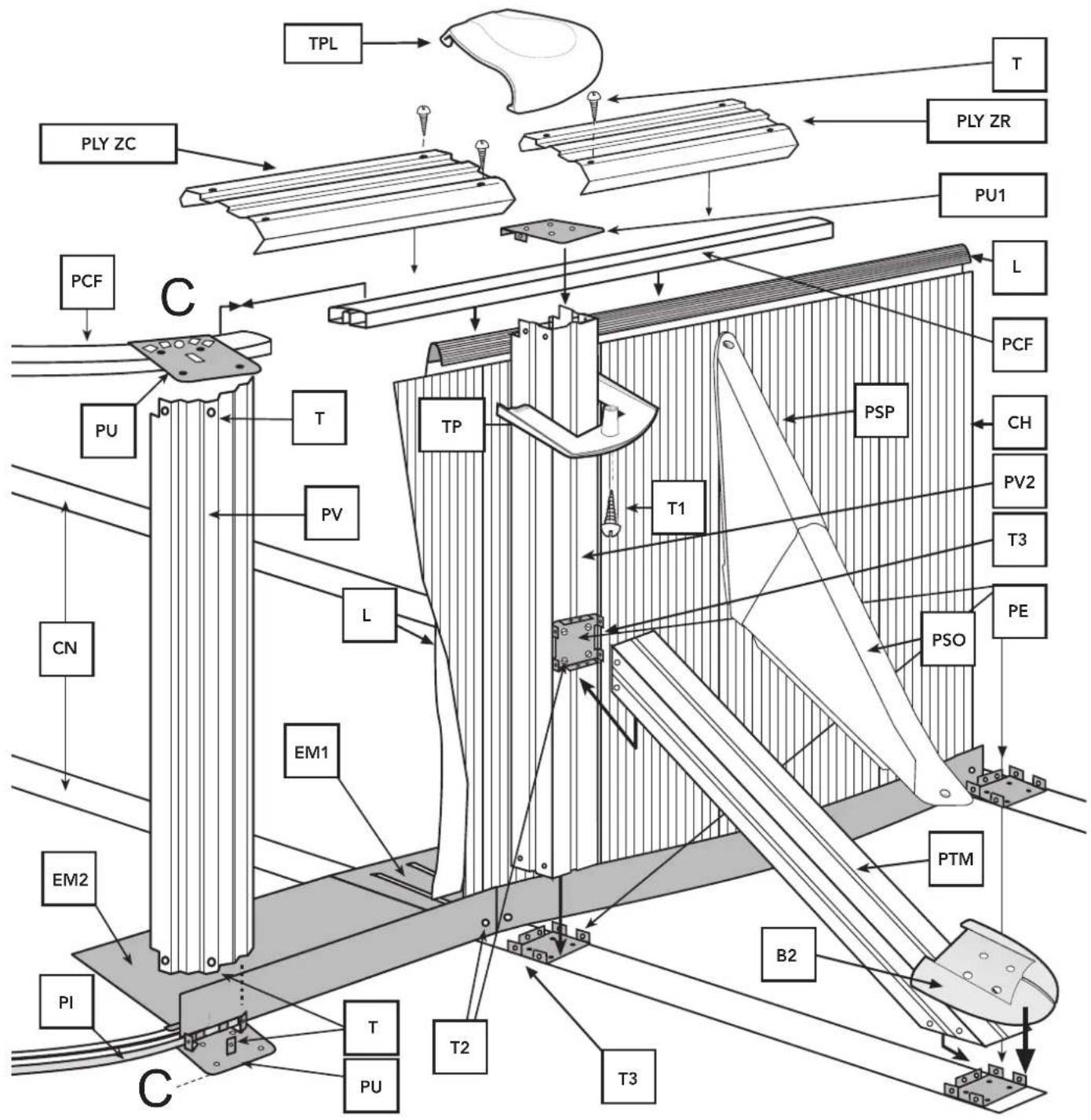
#4
Installation.
It is essential to follow these three steps to achieve a correct assembly:
- Section pieces must only be placed on the curve area located at the lower part of the pool (semi-circumferences), section pieces must not be placed on the straight parts. The lower section pieces are curve (PI) and they have a flap (page 16). Flexible section
parts (PCF) are to be placed on the upper part of the pool in both curve and straight parts (page 21).
- When closing the pool plate (CH) using the screws (TC), make sure the screw heads are facing inwards and the washer and the blind nut outwards (page 19). Tighten the screws without distorting the plate.

Important: The liner used in the manufacturing of all our pools, is developed for exposition to heat and ultraviolet rays for long periods. Therefore, under certain weather and usage conditions, the liner qualities can vary slightly. The interior liner of the pool is manufactured from flexible PVC (thermoplastic). The properties of this material allow optimal installations conditions when the outside temperature is between 20 °C and 25 °C.
Note: Temperature too low: hard and rigid liner; later, too small. Temperature too high: flexible and elastic liner; later, too big.


4.1
Installation of the swimming pool:
We recommend that this is done by two or more adults and on a day without wind.
For your safety, it is very important to wear gloves while assembling the pool.
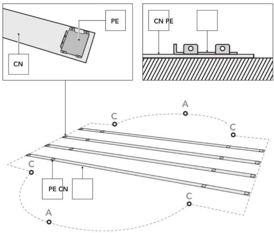
Each strut has 4 drop-forged parts (PE) riveted to it which must be fitted with the tabs upwards. Fully extend the struts parallel to each other across the straight part of the pool.
| CN | CN | ||
| 1000 x550 cm | 4 | 730 x375 cm | 3 |
| 915 x470 cm | 4 | 610 x375 cm | 2 |
| 800 x470 cm | 3 | 500 x300 cm | 2 |
4.2
flowchart
graph TD
    subgraph Input
        EM2["EM2 PU"] <--> T2["T2"]
        T2 --> CN["CN"]
        EM1["EM1"] --> CN
    end
    EM2 -->|A| EM1
    EM2 -->|C| EM2
    EM1 -->|A| PU
    EM1 -->|C| PUPE
    EM2 -->|A| PUPE
    EM2 -->|C| PU
    style EM2 fill:#f9f,stroke:#333
    style EM1 fill:#ccf,stroke:#333
    style PU fill:#cfc,stroke:#333
    style PUPE fill:#fcc,stroke:#333
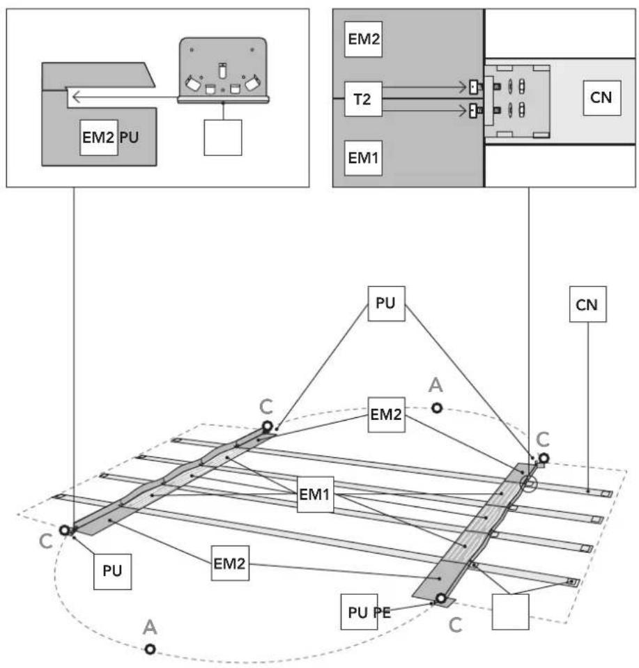
Fitting the metal brackets (EM1) - (EM2): The central metal brackets (EM1) go in the central part (half on one side and half on the other), attached to the tabs on the drop-forged parts (PE) on the struts by the screws (T2). The widest part of the metal bracket should face the inside of the pool and the narrow part should be upright so that it can be attached to the innermost drop-forged part on the strut. Once these brackets are in place and firmly screwed on, fit the outer brackets (EM2) onto the ends, also with T2 screws, ensuring that the joining pieces (PU) to be fitted into the bracket (EM2) slots face towards the point where the relevant half-circular pool end begins (Point C).
NB: When the metal brackets are fixed together the heads of the screws (T2) should face the inside of the pool, and the washers and nuts should face outwards.

natural_image
Two abstract geometric shapes labeled EM1 and EM2, with no text or symbols on the shapes themselves.| EM1 EM2 | EM1 EM2 | ||
| 1000 x 550cm | 3+3 2+2 | 730 x 375cm | 2+2 2+2 |
| 915 x 470cm | 3+3 2+2 | 610 x 375cm | 1+1 2+2 |
| 800 x 470cm | 2+2 2+2 | 500 x 300cm | 1+1 2+2 |
4.3
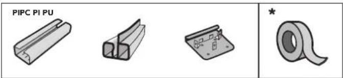
BOTTOM SECTION PIECES (PI) for oval swimming pools. NOTE: These curved SECTION PIECES ARE FOR THE BOTTOMS of OVAL SWIMMING POOLS. Position the bottom section pieces (PI) in each half circumference. Fit a drop-forged part (PU) on each section piece -(Not for 610x375x120). For the section pieces at the ends, fit the drop-forged parts right at the end of them. Join the section pieces with a joining piece (PIPC), leaving a 1cm gap between them.
IMPORTANT: the two half circumferences must be the same length and have equal distribution. If on completing the wall-plate installation it does not fit exactly with the lengths of the half circumferences, you will have to close up the bottom section pieces (or if necessary open them up), always doing the same for both half circumferences. ATTENTION: For correctly positioning the PU parts, take one of the longest BORDER (PLAYAS) pieces and use it to mark the distances
of the PU parts starting from point C. This will facilitate the following steps for positioning the PV vertical profiles (p.18)
NOTE: Drop-forged parts PU under no circumstances shall be affixed to the ground by any means; in the event of doing so, you run the risk of swimming pool breakage and the automatic loss of the warranty.
* Use duct tape to cover parts PU and PIPC on the inside of the pool and thus avoid that may damage the liner.
NOTE: If installed on soil already leveled in the previous steps, we recommend using a slab or paving stone (LO) embedded (at ground level) below each PU pressed profile to avoid that the PV vertical profiles sink in to the ground due to weight of the water.
| (H=132 cm) 1000 x 550 cm: 8 PI + 8 PU |
| (H=132 cm) 915 x 470 cm: 6 PI + 6 PU |
| (H=132 cm) 800 x 470 cm: 6 PI + 6 PU |
| (H=132/120 cm) 730 x 375 cm: 6 PI + 6 PU |
| (H=120 cm) 610 x 375 cm: 6 PI + 5 PU |
| (H=120 cm) 500 x 300 cm: 5 PI + 5 PU |
| (H=132 cm) 610 x 375 cm: 6 PI + 6 PU |
| (H=132 cm) 500 x 300 cm: 6 PI + 6 PU |
* These indications are for each half-circumference

4.4

4.5
915 × 470 cm = 8 × (PV2 & PTM)
800 x 470 cm = 6 x (PV2 & PTM)
730 x 375 cm = 6 x (PV2 & PTM)
500 x 300 cm = 4 x (PV2 & PTM)
610 x 375 cm = 4 x (PV2 & PTM)
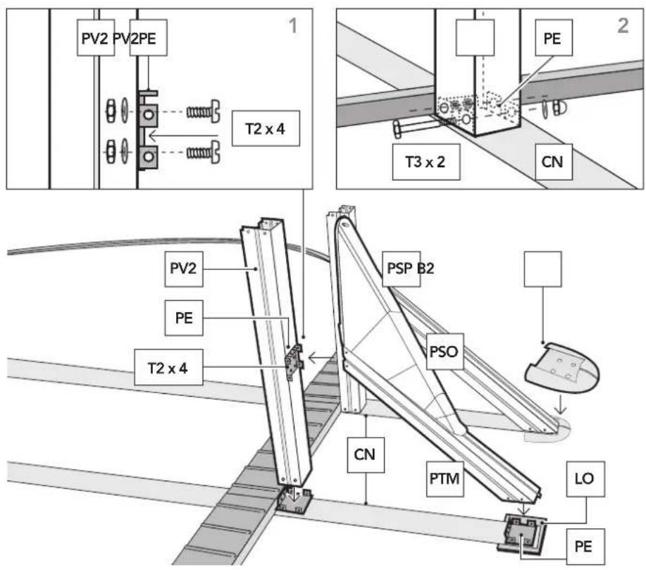
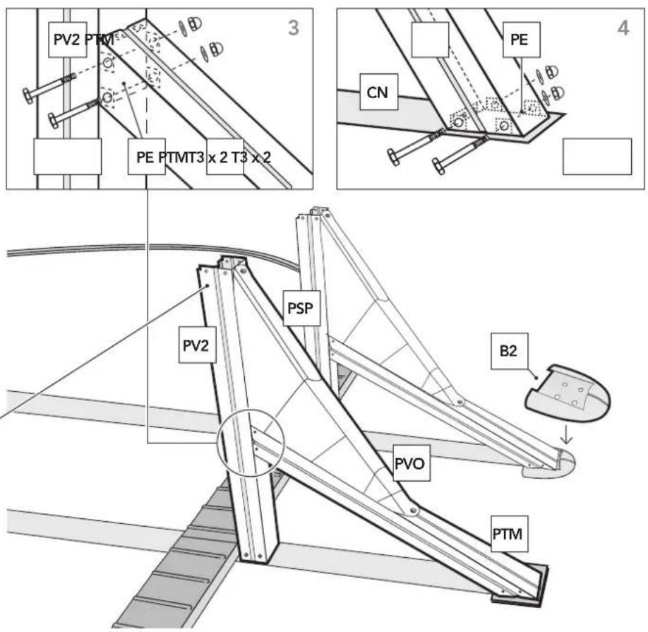
This part of the structure is based on square-sectioned upright supports (PV2) shored up by a cross-support (PTM). Both are attached to the struts by dropforged parts (PE). Each upright support should be fitted as follows:
1- Using T2 screws, attach the outer part of a square-sectioned upright support (PV2) to one of the drop-forged parts (PE), with the longest tab horizontal and uppermost.
2- Place this upright on the drop-forged part on the inner part of the strut (attached to the metal bracket) and hold in place with two through screws (T3). Each strap has 4 riveted pressed parts (PE) that must be situated with their tabs upwards. Position the straps in the entire length. The belts are transversally placed in the straight area of the pool, parallel to each other.
4.6
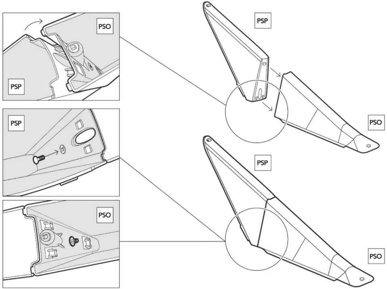
3- Take a cross-support (PTM+PSP+PVO) and fit the squarer end to the drop-forged part half-way up the upright support (PV2) already fitted.
4- Use T3 screws to hold the more rectangular end of the cross-support (PTM) in place on the drop-forged part at the end of the relevant strut. Once the whole upright is in place, tighten all screws firmly. Repeat this process on all the struts until the straight part of the pool is completed. (B2) ENVELOPING JOINT PROTECTORS STRAIGHT
PART: When all the vertical perfiles of the straight part are fixed, you can install the enveloping joint protector B2 to the bottom of the PTM which combine to the strap CN. NOTE: (LO) If the ground is not firm (concrete, etc.), we recommend placing a tile under the ends of the struts (CN) so that the cross-supports (PTM) will not sink down under the weight of the water in the pool.

4.7

natural_image
Illustration of three hand tools: a wrench, a glove, and a screwdriver (no text or symbols)* Important! Before assembly, deburring, using a file and sandpaper, the edge of the closing wall (CH).
FITTING THE WALL PLATING: Fit the wall plating CH vertically on a piece of cardboard (to avoid damaging the area prepared for the installation (checking that the cut-out for the skimmer is at the top of the wall). DO NOT FULLY UNFOLD THE WALL PLATING as this may complicate assembly. Fit the end into place so that the skimmer cut-out is at the middle of one of the curved parts, between 2 joining-pieces (PU).
ATTENTION: For oval swimming pools 610 x 375 x 120 cm and 500 x 300 x 120 cm MAKE SURE that the SKIM-MER hole is centred between 2 PU joint pieces (NOT AT THE MIDDLE OF A HALF CIRCUMFERENCE) before continuing with the assembly.
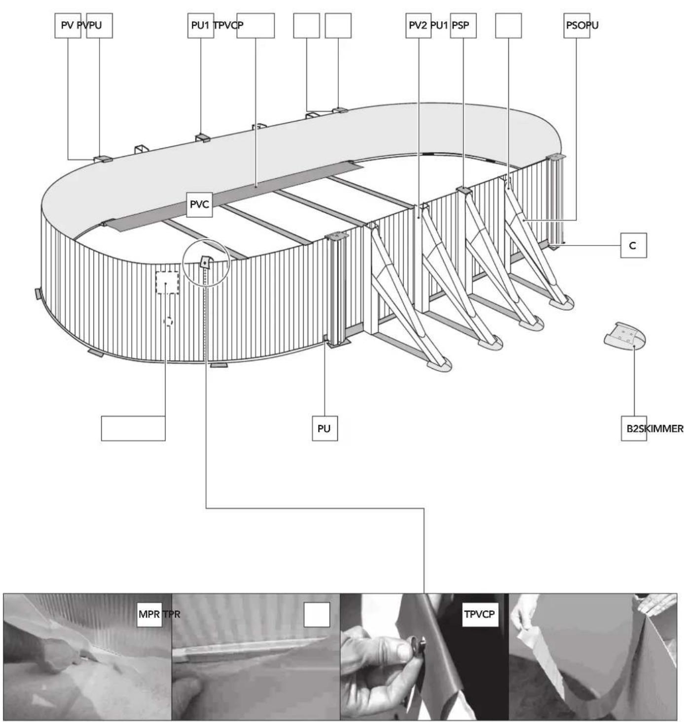
Attach the plating provisionally to the 4 upright supports (PV) at the 4 corners (point C) of the straight part using 4 joining-pieces (PU), each with 3 screws (T) at the bottom and one screw (T) at the top. Attach the plating provisionally with a T screw to one of the upright supports (PV2) at
the middle on both sides in the straight part using a joining-piece (PU1) to stop it from falling. Fit the wall plating all around the pool and screw the ends together, ensuring that the screw heads face inwards and the washers and blind nuts outwards. (Tighten the screws without distorting the material). If the wall plating is too long or too short, adjust the bottom section-pieces in the curved part of the pool to ensure that they are properly butted against each other and against the metal brackets where the curved parts meet the straight part. ATTENTION: If the lower profiles have to be cut, this must be shared among the two half circumferences, meaning, cutting half of the profile dimension from right half-circumference and the other half from the other left half-circumference.
Before cutting, make sure that around all the pool the sheet steel is fitted into the slot of all the curved profiles and is well fitted to the metallic angles in the straight area.


4.8
PROTECTIVE PVC STRIPS (POOL INTERIOR LINING):
Among the pool components there are 2 wide PVC strips (TPVCP) and 1 narrower PVC strip (TPVC). The narrower PVC strip is placed by hooking it to the highest nut of the plate closure and the strip is hung towards the interior of the pool to cover the screw heads. The 2 wider strips are hold with adhesive tape so that they cover the metal brackets that are inside the pool in the straight area. The function of all these strips is to protect the pool liner.
Only if your pool comes with: Blanket (MPR) OR Tapestry (TPR): Warning: it is recommended to clean all dirt from the pool wall and floor with the help of a vacuum cleaner before placing the blanket or tapestry. Place the protective blanket or mat inside the pool, eliminating all folds, adjusting and cutting the excess from the total surface. Carry out the cut so that the lower profiles and the metal parts are covered. This way the liner will be protected when you install it.
4.9
UNFOLDING THE PVC LINER:
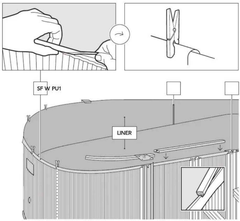
Stretch and extend the liner (L) in the shade so that it recovers its texture at least 2 hours before it is to be positioned. Ideal temperature: in order to handle the liner more easily, ensure that it is fitted at an ambient temperature of between 20 - 25°C.
The liner is oval in shape, to match the shape of the pool walls, i.E. Comprised of a rectangle with a half moon on either side: it can therefore only be fitted in one position. Proper liner placement is essential to prevent folds and wrinkles. The PVC liner must be spread out evenly. Position the liner (L) in the middle of the pool. Unfold the liner along the main axis of the pool and extend the side towards the wall plate. The seam between the bottom and the side must be butted against the base of the wall plating all around the pool bottom, to prevent folds. Before positioning the liner, follow the steps below for assembly:
- Start at one of the straight parts. 2. Position the other half, i.e. the straight part opposite. 3. Continue from one of the ends on the straight part up to the middle of a semi-circumference. 4. Complete the other half of this same semi-circumference. In the event that there is too much, or insufficient, material (liner), adjust by stretching or gathering respectively, all the material of this semi-circumference (distributing it) along the perimeter of the aforementioned semi-circumference. 5 and 6. Repeat steps 3 and 4 respectively in order to complete the pool.
NOTE: if there are creases on the base of the liner or wall, this does not mean that it has to be changed for another since this does NOT indicate a manufacturing defect.
SERIAL NO.: located on the base or wall of the liner. Take note of the serial no. in the box on the instruction sheet for any possible complaints.
°C
20^ - 25^
5^
1°
3^
LINER PVC
6°
2^
4^
SERIAL NO.
Examples
FPR301 20233651
FPR451 HY201907
SP385F GP201901
PV2
SERIAL NO.:
4.10
4.11

Hang the liner sides from the pool walls using the flexible PVC flap (SF). As you hang the liner in place, secure it provisionally with clothes-pegs or with the top PVC section-pieces (without fitting them fully into place and with a 5 cm gap between them). If the liner wall is over large, distribute the excess evenly all around the pool to prevent wrinkles. If it seems too small, stretch it evenly around the pool perimeter. *Note: Some references HAVE NO FLEXIBLE OVERLAP (SF) on the liner side. The liner must be hung by folding it over the wallplate so that an even 3-4 cm overlap is left.
ATTENTION: In 6-7 m long pools (120 cm height), the conform overlap has to be 13-14 cm.

natural_image
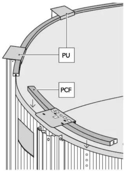
Simple line drawing of a 3D object resembling a folded paper or bracket, labeled 'PCF' (no additional text or symbols)FLEXIBLE TOP SECTION PIECES (PCF) for Oval Swimming Pools
NOTE: these flexible section pieces are for the tops of oval swimming pools.
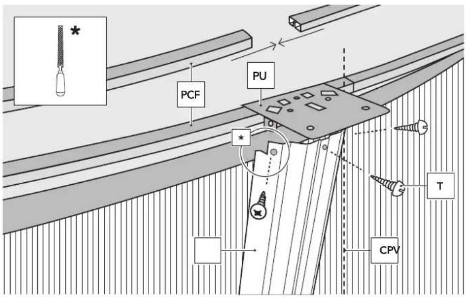
They are fitted on top of the liner once this has been fitted over the swimming pool sheet and they do not need to be joined together. They are positioned one after the other, and when the perimeter is completed, the extra length is cut off. Place each PU piece over the top section pieces; they must be lined up with those located in the lower part.
4.12
* Important! Before assembly, deburring, using a file and sandpaper, the end of each edge.
Screw the upright support (PV) to the appropriate bottom and top joining-pieces with 3 T screws each. Repeat this procedure until the half-circle is completed. Join the section-pieces together and check by looking
at the ribbing on the wall-plating that the upright supports are properly vertical.
NB: Check that the 3 + 3 (top and bottom) T screws are all fitted on each upright support and joining-piece all around the pool. Fill the pool to a depth of 2 cm of water and extend the liner to eliminate all wrinkles.
If the water does not lie evenly over the whole of the pool bottom, the ground is not level enough. Remove the liner and level the ground.
4.13
* Important! Before assembly, deburring, using a file and sandpaper, the ends of each PLY.
Installing the trim pieces PLAYA (PLY):
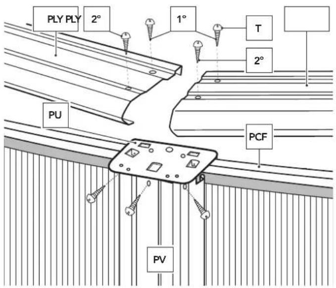
Take care that the trim pieces do not fall into the pool during fitting, as they may damage the liner. Fit each trim piece supported on two consecutive PU with the rounded part outwards. Each trim piece has four holes (two inside and two outside) for fixing to the union pieces. Start fixing each trim piece to the union pieces, but only place the inside screws (1) on each side (and do not tighten down, so that there is some flexibility between them). When all the trim pieces have been placed, check again that the vertical sections are properly vertical. If not, correct their position. Next, place
the outside screws (2) and fasten down all the screws in the structure.
WARNING: Do not climb onto, walk or sit on, jump or dive off the TRIM finishing pieces.

natural_image
Technical line drawing of a mechanical joint or bracket assembly (no text or symbols)4.14
natural_image
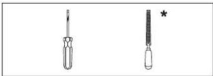
Two screwdriver tools shown in line drawings, one with a handle and the other with a handle (no text or symbols)* Important! Before assembly, deburring, using a file and sandpaper, the ends of each edge.
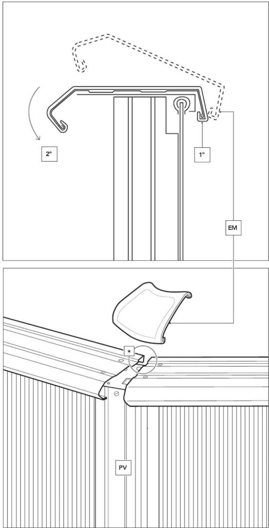
PLACING THE FLEXIBLE JOINT PROTECTORS (EM only for pools of 120 cm):
The flexible joint protectors are fitted to the joints between the trim pieces.
To fix them, start by fixing the back part (inside the pool) to the trim piece and with the aid of a screw-driver lever the front ribs over until they fit to the trim piece.
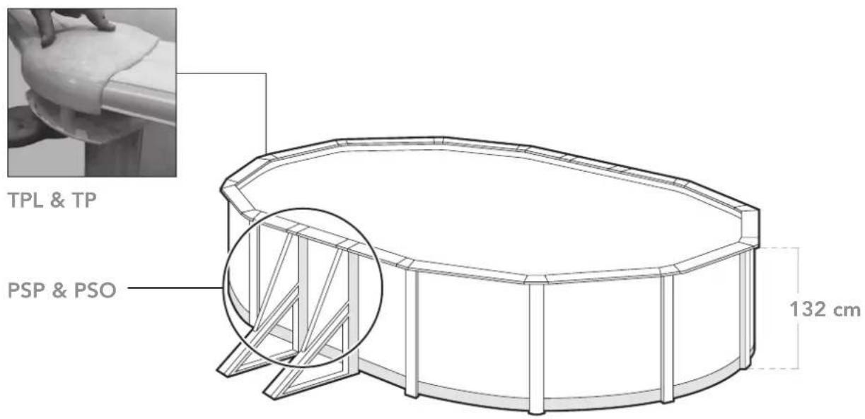
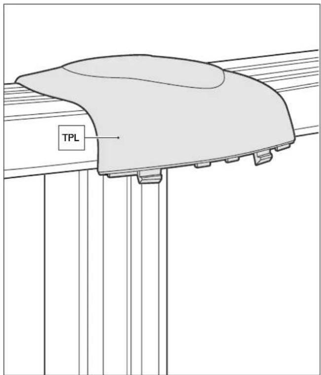
JOINT PROTECTORS: TPL and TP. (only for pools of 132 cm)
These pieces are to be fitted joining and protecting the trim pieces. Joint protectors are made up of 2 elements: Strim Piece protector (TPL) and Vertical Section protector (TP). First, the back side of TPL has to be fixed to the back side of the 2 trim pieces. Then, it
has to be tightened to the front side of the pool, fixing the TPL verge to the PU1 hole. Now, fix TP to TPL by the lower side using a screw T1 to join them. This process is to be repeated for all the joint protectors. ATTENTION: TP notch has to be removed to fix PV2 in the straight areas of the pool.

natural_image
Technical line drawing of a screwdriver with a separate screw tip (no text or symbols)


4.16
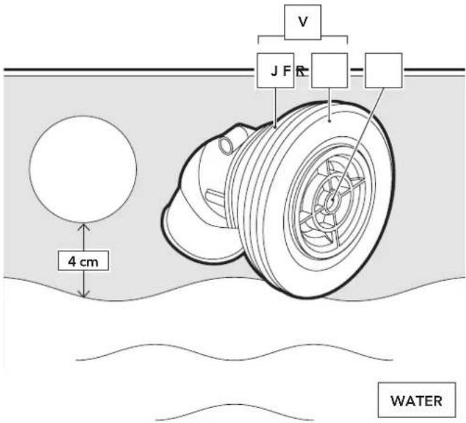
FITTING THE RETURN VALVE (V): (IMPELLER NOZZLE: V)
This valve is located at the bottom of the pool wall, and water is returned to the pool through it after treatment in the treatment unit. Start pouring water into the pool through a garden hose, and stop 4 cm below the bottom of the valve hole (check the liner is clean before filling the pool). Mark the position of the hole on the liner with a felt pen and make a cross-shaped cut in the centre of the mark with a stanley knife or similar. Do not cut beyond the edge of the hole. Place inside the pool through the cut, with a seal (J) and a friction ring (F). Cut the protruding part of the liner.
Fit the other seal (J) and the other friction ring (F) and tighten firmly with the nut (T). Insert the return hose (M) which goes from the outlet of the treatment unit to the return valve (V), and secure it with the clamp (A).

4.17
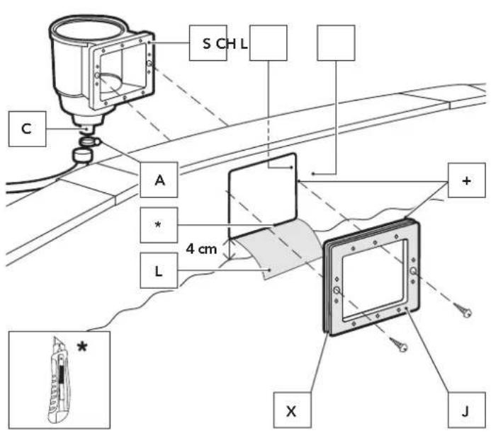
ATTACHING THE SKIMMER BODY (S) TO THE OUTSIDE OF THE POOL:
Continuare a rimpire d'acquaFill the pool with water until the level is 4 cm from the bottom of the perforation for the skimmer. Using a Stanley knife, cut the liner (L) inside the pool opposite the perforation. Locate the double seal (J) so that the wall plate and liner are within the groove (X) made for this purpose and fit the two shorter screws into the larger centre holes from the inside of the pool through the double seal and the liner. Screw them into the center holes on the skimmer (S). Cover the connecting bushing (C) and the water treatment unit inlet with Teflon. Screw the connecting bushing (C) tightly to the skimmer, connect one end of the hose to the skimmer connecting bushing (C) using a clamp (A), and fit the other end to the treatment unit inlet. Clamp this end also.
NB.- Fit Teflon on all water hose connection threads to ensure leak-tightness.

natural_image
Line drawing of a pipe outlet with a coiled tube, mounted on a wall (no text or symbols)4.18
FITTING THE SKIMMER FRAME (M):
Ensure that all holes are lined up properly (seal to wall plate perforation to skimmer). Screw 10 remaining screws loosely through the frame to check that the fit is correct. Then tighten the screws a little more one by one in the order indicated. Finally, tighten them fully in the same order.
LAST DETAILS: Pressure fit the trim part of the skimmer frame (Z). To finish, introduce the flap (K) through the rectangular gap (delicately press the two ends and fit the protrusions). Place the basket (O) into the skimmer and the skimmer body cover (TS).


#5
Maintenance and use.
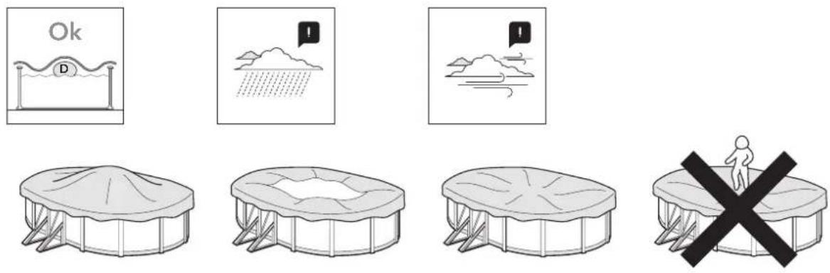
→ The pool water level must always be at least 15 cm from the edge of the upper edge of the same.
→ During the season for use of a pool kit, use the filtering system once a day to assure complete recycling of all the water and always when the pool is not used for bathing (see purifier manual).
→ During the season for using the pool, regularly verify the obstruction level of the filtering means.
→ Revise all the screws of the pool, and the possible corrosion points as much as possible.
→ Never completely empty the pool. There is a risk of seriously damaging the pool structure if there is not sufficient water level.
→ Not respecting the maintenance instructions can cause serious health risks, especially for children.
→ The use of a pool kit involves respecting safety instructions defined in the maintenance and usage guide.
→ Never leave a pool kit for installation of the ground outside and empty.
→ Regularly clean the PVC liner and the water level line with non-abrasive products. Periodically clean the bottom fold layer at the joint with the side liner because dirt can collect at this point. If you accidentally make a small hole in the liner, it can be repaired with AR202 or V12 patches.
→ The summer covers (isothermal) protect your pool from insects, dust, leaves, etc. and prevent loss of water temperature. Always place it with the bubbles in contact with the water.

RESPECT THE ENVIRONMENT DO NOT TAKE APART THE POOL UNLESS IT IS STRICTLY NECESSARY. IF YOU DO SO, PLEASE REUSE THE WATER. WATER IS A SCARCE GOOD.
When your pool reaches the end of its useful life, it should be disassembled; the different materials (plastic and steel) should be separated and taken to the disposal point indicated by local authorities.
WINTER-SEASON:
A) If you choose not to dismount the pool:
1- Clean the liner bottom and sides with a non-abrasive product.
2- Treat the water with a chemical product for wintering. We recommend using LIQUID WINTERISER instead of floats with solid product to avoid discolouring the liner.
3- Leave the pool full of water considering:
a) For pools with skimmer and refulling pipe, reduce the water level 5cm underneath the skimmer and close the refulling pipe with the screw tap which is included with the filter.
b) For pools with exhaustion and refulling pipes, reduce the water level 20 cm from the superior edge of the pool and close the pipes using the screw system incorporated.
4- Disconnect the pipes. Do not dismount the skimmer and the refulling and exhaustion pipes.
5- Protect the pool with a winter cover, and put a floating element between the cover and the water, in order to protect it from frost.
6- Filter: disconnect it from the pool. Clean it, empty the sand or remove the cartridge, dry it and keep it in a covered and sheltered from dampness place.
7- Accessories: remove every accessories (ladder, alarm, spotlight, pole...), rinse them with soft water and tidy them away.
TO RUN THE POOL AGAIN: Remove the winter cover, install the filter, change at least 1/3 of water and realize a chlorine treatment. Switch on the filter for at least 8 hours in an uninterrupted way, respecting the continuous working period indicated in the filter manuals.
B) If you choose to dismount the pool:
1- Empty the pool. Measures: Filter, Automatic pump for handling clean water or communicating vessels system. Communicating vessels system: Use the hose from your filter with the smallest cross-section. Fix a weight to one of its end and plunge it into the swimming pool. After this, sink the whole hose, until there is no air inside. With one hand, and under the water stop up hermetically the end of the hose and take it to the emptying point. Remove hand, and water will start running. Do not use this water for watering the plants, because it contains chemical products.
2- Clean every pool constituents with a sponge and a soap product with a neutral pH. Dry them and tidy them away in a dry and clean place.
That's normal that after having installed and dismounted the pool several times, the P.V.C liner dilate and loose its elasticity.
TO RUN THE POOL AGAIN: Read another time this manual instructions from the beginning.
CHIMICAL MEASURES:
Please read carefully the chemical product manufacturer instructions. WARNING: Keep chemical products in a clean, dry and out of children place. Important:
Every products used have to be compatible with the P.V.C liner.
→ First filling: Analyse the water pH and chlorine (Cl) and adjust them to the optimal levels: pH: 7,2–7,6; Chlorine: 0.5–2 ppm.
→ Chlorine treatments: Consist in increasing the chlorine level until approximatively 20 ppm to eliminate germs and seaweeds. This process has to be done only when the pool water comes from rivers or ponds, ... or if it stayed a long time without any treatments.
→ Checking: Check at least once a week the chlorine levels (use a chlorine and pH analyser). In the same way, we advise to add an algicid to prevent seaweeds appearance.
Never have a swim before the chlorine level stabilization. Do always use a floating dispenser for the chemical product (tablets) dissolution. The chemical product measuring out has to be done in accordance with: Your pool water volume, the bathe frequency, the climatic conditions, the water temperature and the location. Do always move the water and wait for the chemical product dissolution before adding another one. Wait approximatively 12 hours between any pH, chlorine or algicid adjustment using the filter system.
MECHANICAL MEASURES:
Check the filter, the skimmer, the valves and the pipes are well connected to the pool. Do consider high water temperature will involve more time for the filtering. Theoretic filtering time = Water volume / Filter system discharge (generally 8h/day with water temperature of 21°C), (Ideal: 2h in the morning – 4h around midday – 2h in the afternoon). PLEASE RESPECT THE CONTINUOUS WORKING PERIOD INDICATED IN THE FILTER MANUALS.
VACUUM CLEANER (MANUAL OR AUTOMATIC):
Only for pools with skimmer. Connect an hose extremity to the brush head and immerse it into the water to make it fill in. Connect the other pipe extremity to the exhaustion adapter (TA) and place it above the skimmer basket. Switch on the filter in the FILTER position and begin to clean the bottom. Pay special attention to areas with folds where dirt accumulates.
BOTTOM CLEANER VENTURY STYLE:
Connect a garden hose to the bottom cleaner join and introduce it into the pool. Open the tap until a normal pressure to make the water flow out against the bottom of the pool, producing in that way an ascendant stream which leave the dirt into the filter (bag) which is adjust on the bottom cleaner.
PROBLEM CAUSE SOLUTION
| Muddy water | Bad filtration. High PH. Organic residues in excess | Perform a return was of the filter.Add PURIFIER in tablets using a dispenser.Perform a shock chlorinating. |
| Green water Seaweed or mud formation | Gently clean the bottom and walls of the pool.Analyse the pH and adjust it to between 7.2 - 7.6.Add algicide and liquid purifier. | |
| Brown water Presence of iron or manganese | Analyse the pH and adjust it to between 7.2 - 7.6.Perform a shock chlorinating. Add liquid purifier. | |
| Incustrations Presence of Calcareous in the water | Analyse the pH and adjust it to between 7.2 - 7.6.Add anti-calcareous once a week. | |
| IEyes and skin irritations. Bad smell. | Misadjusted PH. Organic residues in excess | Analyse the pH and adjust it to between 7.2 - 7.6.Perform a shock chlorinating. |
EMPTYING - COMMUNICATING VESSELS SYSTEM

natural_image
Diagram showing four sequential stages of a fluid system with pipes and tanks, no text or symbols present.#6
Accessories.
natural_image
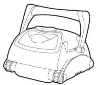
Line drawing of a portable water purifier device (no text or symbols)
natural_image
Line drawing of a portable electronic device with fan and control knobs (no text or symbols)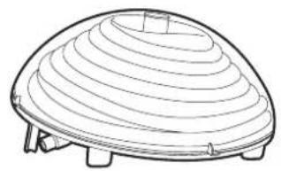
natural_image
Line drawing of a dome-shaped container with concentric layers and support legs (no text or symbols)CLEANERS HEAT PUMPS HEATING SYSTEMS
natural_image
Simple line drawing of a microphone (no text or symbols)
natural_image
Line drawing of a cylindrical storage tank with support structure on a flat base (no text or symbols)
natural_image
3D diagram of a cylindrical container with internal structural beams (no text or symbols)ISOTHERMIC COVERS
WATER TREATMENT FLOOR TAPESTRY

natural_image
Simple line drawing of a cylindrical container with a curved top and internal structure (no text or symbols)
natural_image
Technical line drawing of a mechanical lever assembly (no text or symbols)IMPORTANT: you can view the entire range of products on our site: www.grepool.com

Guarantee card
Keep your manual with the purchase justification (payment receipt) for any type of reclamation.
Any reclamation against guarantee should be made by an online declaration, via the www.service-gre.com website, together with receipt of purchase. You may be asked for photographs to justify the claim. No returns of material will be accepted without previous agreement. The client will support all costs of all returns of goods, (packaging and transport).
AFTER VERIFICATION AND CONFIRMATION OF A MANUFACTURING DEFECT
→ The products that eectively show defects will be repaired or will be replaced free of transport costs.
The guarantee is limited to the repair or replacement of the defective part. It does not include, under any circumstance, the payment of compensation for harm and damages.
THE GUARANTEE IS NOT APPLICABLE IN THE FOLLOWING SITUATIONS:
→ Use of materials that do not comply to our instructions.
→ Damages caused by mishandling or an installation not complying with the instructions.
→ The maintenance instructions were not followed.
→ Inappropriate or wrong use of the chemical product.
IMPORTANT:
Manufacturas Gre interchanges components in exchange for others to be veried. If, after the verification no anomaly or dysfunction is detected, Manufacturas Gre reserves the right to invoice the client for the cost for transport and other diverse expenses.
DURATION OF THE GUARANTEE:
Gre pools are subject to the legal 2- years guarantee established by the General Consumers and Users Defence Act counting from the date of purchase and according to the terms of the same. We remind you that for the guarantee to be applicable the purchase receipt should be presented and/or the return of the product. Manufacturas Gre also grant an additional 2-year commercial guarantee for this pool model, that is to say making a total of 4 years, exclusively regarding the metallic parts of the pool structure. This additional commercial guarantee will not act the rights of the consumer according to the legal guarantee.
The following is excluded from both guarantees:
→ The PVC Liner, in the case of disassembly and re-assembly of the pool
→ Stains or decolouring that can appear in the liner due to its use
→ Damages to the pool derived from poor ground preparation where the pool is located
→ Damage to the pool derived from burial of the same
→ Any damage to the pool derived from misuse of the same, according to the instruction manual
Likewise, all plastic parts are excluded from the additional commercial guarantee, that is to say:
→Theliner
→ Any decorative part
To be able to benet from the guarantee, your pool should include this document.
Guarantee valid for pools sold after 1 January 2016.
→ Liner: 2 years for the seams and water tightness in normal conditions of use. The guarantee does not include: Ripping, tears, breakages, stains (caused by pouring treatment products directly into the water), stains linked to the growth of algae, stains related to the decomposition of foreign bodies in contact with the liner, stains and decolouring resulting from the action of oxidising products, colour maintenance and wear due to friction of the material over diverse surfaces. Deformation of the liner that has been left without water for 24 hours (never completely empty the pool). You should keep the label with the serial number of the liner that is on the product and on its packaging. This number and a sample of the liner will be required for any eventual reclamation against the guarantee.
→ Filter group: The pump has 2 years guarantee (electrical problem), in normal conditions of use. The guarantee does not cover breakage of parts (pump base/sand deposit, pre-Iter cover, multi-directional trap...), wear due to a poor connection, use of the pump without water, wear due to abrasion or corrosion (the Iter group should be located in a cool and dry position, kept protected from water splashing).
→ Other components: 2 years.
THE FOLLOWING IS NOT INCLUDED IN THE GUARANTEE:
→ Cuts in the liner
→ The assembly and Iter connection
→Theassembly
→ The lling with water
→ Installation of the edges
→Thewintering
→Maintenance
AFTER SALES SERVICE WITHOUT GUARANTEE:
The guarantee is valid in all the UE countries, UK and Switzerland. GRE oers the buyer -in addition to the rights of guarantee from the seller that correspond by law and without limiting them- an additional right according to the conditions of the following obligations guaranteed for new products.
→ In the case of problems, contact us: www.grepool.com/en/after-sales


MANUFACTURAS GRE S.A.
Aritz Bidea, 57 BELAKO INDUSTRIALDEA, APARTADO 69, 48.100 - MUNGUIA (VIZCAYA) ESPAÑA. Telf.: (34) 94 674 11 16 · Fax: (34) 94 674 17 08
e-mail: gre@gre.es www.grepool.com
N° GUARANTIE
We reserve the right to change all or part of the articles or contents of this document, without prior notice

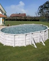
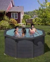
- Steel wall swimming pool.
- 03 - 04
- 05 - 07
- 08 - 13
- 14 - 27
- 28 - 29 #6 30
- #1
- Safety precautions.
- Non swimmers safety
- Safety devices
- Safety equipment
- Safe use of the pool
- This can make a life-saving difference in the event of an emergency:
- WARNING
- Read the instructions carefully and keep for future reference.
- IF YOU HAVE ANY PROBLEM, CONTACT US! www.grepool.com/en/after-sales
- #2
- Preparation of the site.
- Installation site
- Recommendations for choosing the best location for your pool
- 2.1
- Mark the installation area:
- Levelling:
- 2.3
- Finishing:
- #3
- Components.
- Important.
- #4
- Installation.
- 4.1
- Installation of the swimming pool:
- 4.2
- 4.3
- 4.5
- 4.6
- 4.7
- 4.8
- PROTECTIVE PVC STRIPS (POOL INTERIOR LINING):
- 4.9
- UNFOLDING THE PVC LINER:
- LINER PVC
- SERIAL NO.
- 4.10
- 4.11
- FLEXIBLE TOP SECTION PIECES (PCF) for Oval Swimming Pools
- 4.12
- 4.13
- Installing the trim pieces PLAYA (PLY):
- 4.14
- PLACING THE FLEXIBLE JOINT PROTECTORS (EM only for pools of 120 cm):
- JOINT PROTECTORS: TPL and TP. (only for pools of 132 cm)
- 4.16
- FITTING THE RETURN VALVE (V): (IMPELLER NOZZLE: V)
- 4.17
- ATTACHING THE SKIMMER BODY (S) TO THE OUTSIDE OF THE POOL:
- 4.18
- FITTING THE SKIMMER FRAME (M):
- #5
- Maintenance and use.
- WINTER-SEASON:
- A) If you choose not to dismount the pool:
- B) If you choose to dismount the pool:
- CHIMICAL MEASURES:
- MECHANICAL MEASURES:
- VACUUM CLEANER (MANUAL OR AUTOMATIC):
- BOTTOM CLEANER VENTURY STYLE:
- #6
- Accessories.
- Guarantee card
- AFTER VERIFICATION AND CONFIRMATION OF A MANUFACTURING DEFECT
- THE GUARANTEE IS NOT APPLICABLE IN THE FOLLOWING SITUATIONS:
- IMPORTANT:
- DURATION OF THE GUARANTEE:
- THE FOLLOWING IS NOT INCLUDED IN THE GUARANTEE:
- AFTER SALES SERVICE WITHOUT GUARANTEE:
- MANUFACTURAS GRE S.A.
Brand : GRE
Model : KITPROV613
Category : Above ground pool