
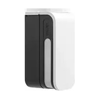
VX-402REC - Motion detector OPTEX - Free user manual and instructions
Find the device manual for free VX-402REC OPTEX in PDF.


| Product Type | Motion Detector (PIR) |
| Brand | Optex |
| Model | VX-402REC |
| Detection Method | Passive Infrared (PIR) |
| Detection Range | 12 m (40 ft) @ 25°C |
| Detection Angle | 90° |
| Mounting Height | 1.8 - 2.5 m (6 - 8 ft) |
| Power Supply | 12 VDC ±10% |
| Current Consumption | 20 mA (typical) |
| Alarm Output | NC/NO relay, 100 mA max |
| Tamper Protection | Yes, cover tamper switch |
| Operating Temperature | -10°C to +50°C (14°F to 122°F) |
| Dimensions (W x H x D) | 62 x 97 x 42 mm (2.4 x 3.8 x 1.7 in) |
| Weight | 80 g (2.8 oz) |
| Material | ABS plastic |
| LED Indicator | Red LED for alarm, green for warm-up |
| Warm-Up Time | 30 seconds |
| Pulse Count | Selectable: 1, 2, or 3 |
| Installation | Wall or ceiling mount, bracket included |
| Maintenance | Clean lens with soft cloth, avoid solvents |
| Security Features | Tamper detection, anti-masking (optional) |
| Spare Parts | Mounting bracket, screws, connectors |
| Repairability | Replaceable relay module |
| Certification | CE, FCC |
Frequently Asked Questions - VX-402REC OPTEX
User questions about VX-402REC OPTEX
0 question about this device. Answer the ones you know or ask your own.
Ask a new question about this device
Download the instructions for your Motion detector in PDF format for free! Find your manual VX-402REC - OPTEX and take your electronic device back in hand. On this page are published all the documents necessary for the use of your device. VX-402REC by OPTEX.
USER MANUAL VX-402REC OPTEX
Standard model Voice Warning model


FEATURES
2 YEAR WARRANTY
Voice Warning Function (VX-402REC Only)
VX-402REC is capable of delivering two kinds of audible messages to an intruder. This has been proven as an effective means of deterring BREAK-INS.
Easy Recording with Built-in microphone or External apparatus (VX-402REC Only)
The VX-402REC detector records warning messages by either of two different ways: speak direct to its built-in microphone or connect an external sound source to the detector.
Limited Detection Range Function
The detection range of the VX-402 can be limited to avoid detecting unwanted objects. By limiting the detection range, false alarms due to unwanted movement (i.e. cars, persons or animals outside the protected area) can be reduced.
Size Judging Function
VX-402 is designed to discriminate between large and small animals. By utilizing this ability, false alarms due to small animals can be reduced.
Bright Light Disturbance Immunity
VX-402 is equipped with Double Conductive Shielding (Patent Listed). This shielding greatly reduces the chance of false alarms due to car headlights, sunlight and other ambient light sources.
Detection Area Extension Function
The detection area can be easily extended by using its slave units.
Directional Detection Function
VX-402 can distinguish movement direction by using slave units. This function increases the operational reliability and allows for use in new applications (Directional Security).
CONTENTS
1.INSTALLATION HINTS 2
2.DESCRIPTION AND OPERATION 3
3 INSTALLATION 4
4 WIRING 5
5 RECORDING 6
6 SETTING & ADJUSTMENTS
7.FUNCTIONS 10
8 OPERATION TEST 13
9.TROUBLE SHOOTING 14
10.SPECIFICATIONS 16
11 DIMENSIONS 16
Safety-Related Precautions
- Before installation, make sure to read this instruction manual carefully for safe and effective product operation.
•After reading this installation manual, make sure to keep it in a convenient place for future use.
 | This icon denotes a situation involving the risk of serious injury or even death, if the warning given is ignored. |
 | This icon denotes a situation involving the risk of serious injury or damage to property if the warning given is ignored. |

This icon indicates actions to be avoided. Details of the actions to be avoided are written beside or near icon.

This icon indicates instructions that should be strictly followed.
 | Never use this product for any application except purpose for detecting moving target such as a human or a car. In addition, never use for any activation for a shutter or other. It may cause hazards. |  |
 | To avoid the risk of electric shock, never touch the main body of the product with wet hands. (Also, if the product is wet after rain do not touch it.)  |  |
 | Never attempt to disassemble or modify the product, which increases the risk of fire or damage of the product. |  |
 | Never attempt to connect the terminals to units which require higher power supply or current draw than its rating. It increases the risk of fire or damage to the product. |  |
 | Avoid applying water in directly from brackets, houses, or otherwise splashing water directly onto the product. It increases the risk of damaging the product. |  |
 | Clean and inspect the device periodically for safe operation. If any defect is detected, ask your local supplier to repair the device. |  |
1. INSTALLATION HINTS
- Install the sensor perpendicular to the ground to making upper detection area parallel to the ground.
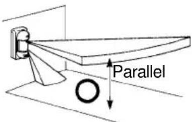
- Installation height is 0.8m-1.2m (2.7ft-4ft)

4.VX-402 is designed to protect any light disturbances. However, too much light may cause unstable condition with the sensor, such as; strong sunlight directed or reflected exactly into the sensor's field of view. It is recommended to avoid such installation.

natural_image
Simple line drawing of a sun and an arrow, no text or symbols presentIf the sensor is installed with some angle to the ground, operational reliability of the sensor may be decreased.

natural_image
Simple line drawing of a mechanical component with an X mark indicating a dimension (no text or symbols)- Mount the sensor so that a majority of traffic flow is across the detection pattern.

natural_image
Simple line drawing of a curved object with directional arrows, no text or symbols present- Avoid pointing the sensor towards moving objects (i.e. swaying trees, bushes, flags, etc.). If moving objects are unavoidable, please refer to Trouble Shooting reference for proper installation.

natural_image
Diagram showing light rays reflecting off a surface with a cross mark (no text or symbols)2.DESCRIPTION AND OPERATION

3.INSTALLATION
3-1.Before the Installation

natural_image
Diagram of a mechanical device with rotating arm and base, showing no text or symbolsLoosen the lock screw and remove the cover.

natural_image
Technical line drawing of a mechanical assembly or enclosure with no visible text or symbolsLoosen the plate lock screw [about 10mm (0.4")].

natural_image
Technical line drawing of an electrical enclosure or switchgear assembly (no text or symbols visible)Remove the plate by sliding it down and away from the unit base.
3-2. Wall Mount

Pull the wire through wiring hole and install the plate on the wall by using provided mounting screws (two places).

IMPORTANT
• Install the unit perpendicular.
• Installation height must be between 0.8m and 1.2m (2.7 ft and 4 ft).
- Secure a space 110mm (4.4") or more to the upper part of plate for opening and closing of the cover.
Lead the wire to the groove on the unit base, through the wiring hole at the terminals. Apply an adhesive sponge pad over the wiring hole. Hook the unit base onto the plate.
Fasten the plate lock screw and connect the wires to the terminal.
Adjust the DIP switch, detection area and sensitivity. Secure the cover with the lock screw.
Surface wiring
(a) Upper Knockout Wiring Hole (b) Lower Knockout Wiring Hole
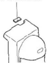
Remove the upper wire knockout.
natural_image
Simple line drawing of a toilet with a lid and handle (no text or symbols)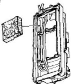
natural_image
Technical line drawing of a mechanical device with internal components and a separate inset showing a textured surface (no text or symbols)Lead the wire through the upper side of the unit base, lead the wire to the wiring slit then through the wiring hole.
natural_image
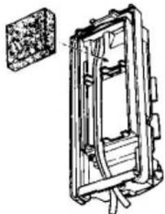
Technical line drawing of a mechanical assembly with no visible text or symbolsRemove the lower knockout of the unite cover, lead the wire through the knockout hole.
3-3.Pole Mount
An installation pole with an outside diameter of 43mm(1.66") must be used.
(Standard U.S.1 ^1/4 "pipe has an outside diameter of 1.66".)

For outdoor wiring, bury piping as deep as possible. Some sites will require metal coated cables for underground wiring work.
Avoid aerial wiring
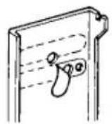
Peel off one of the two sealings along the dotted line.
Wiring Sponge Pad
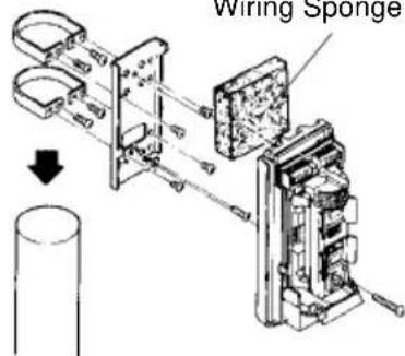
Fix bracket onto mounting plate with supplied screws (M4x6,4pcs). Place the bracket around the pole and tighten firmly with pole locking screws.
3-4. Electric Box Mount

For connections to single gang electric boxes, follow instructions for wall mounting.
natural_image
Technical line drawing of a mechanical assembly with threaded fastener and housing (no text or symbols)
Conduit can be installed directly into the bottom of the unit by removing the knockout on the bottom on the cover.
4.WIRING
VX-402
POWER INPUT:9.5 - 18VDC
![ALARM OUTPUT:[NC/NO] SELECTABLE SPARE SPARE AUX INPUT:[NC] TAMPER:[NC] JUMPER](/content/2026/06/1274640/images/df509e53d5eac1d310db2e68179aaa09d620a6240ec3b3c6a3ed5015af305184.jpg)
VX-402REC
POWER INPUT:9.5 - 18VDC
![ALARM OUTPUT:[NC/NO] SELECTABLE VOICE OUTPUT VOICE CONTROL INPUT AUX INPUT:[NC] TAMPER:[NC] JUMPER](/content/2026/06/1274640/images/666cd1c9dea84ae55b3b9719354acbd8dc1719b8ebcbcdd5f92abbbcddeee018.jpg)
IMPORTANT
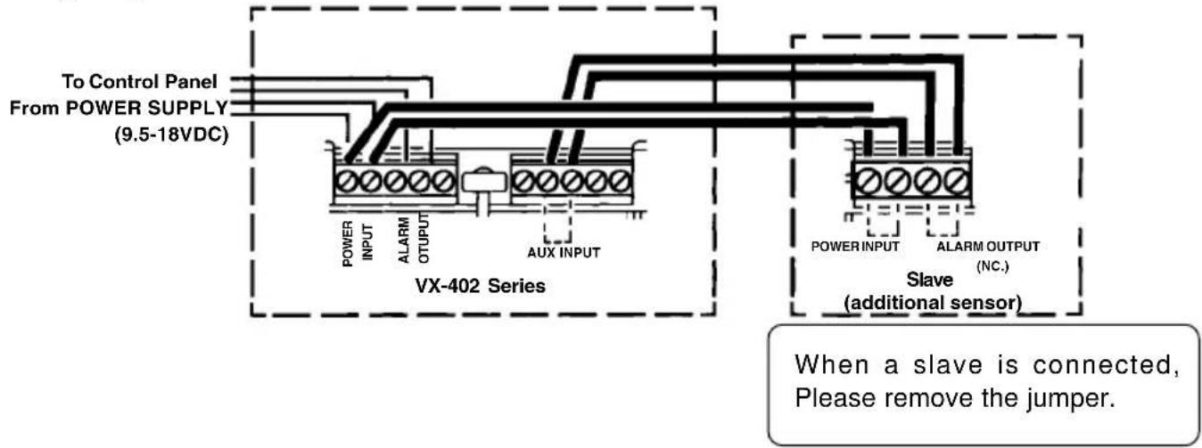
- Do not remove jumper while slave is not connected. Otherwise, VX-402 series continue to give the alarm.
- Use AUX INPUT terminal only when slave is used.
Power wires should not exceed the following lengths.
| WIRE GAUGE | VX-402 VX-402REC | |||
| 12V 14V | 12V 14V | |||
| AWG 22(0.33mm2)2 | 200m(670ft) | 400m(1330ft) | 110m(370ft) | 230m(770ft) |
| AWG 20(0.52mm2)3 | 40m(1130ft) | 640m(2130ft) | 180m(600ft) | 360m(1200ft) |
| AWG 18(0.83mm2)5 | 10m(1700ft) | 1020m(3400ft) | 290m(970ft) | 570m(1900ft) |
5.RECORDING
The VX-402REC detector records warning messages by either of two different ways: speak direct to its built-in microphone or connect an external sound source (tape-recorder or computer etc.) to the detector.
5-1.Description for Recording
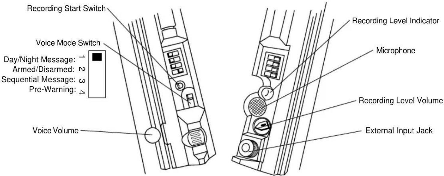
5-2. Recording Method

flowchart
graph TD
    A["Microphone"] --> B["Set the detector's recording level volume for max."]
    C["Sound Source"] --> D["Connect the earphone, headphone jack or line out jack of the external sound source with the detector's jack using connection cable with monaural plugs. Set the detector's recording level volume for min."]
    B --> E["2 Choose track A or track B on which to record. * To record on track A (track B), set DIP switch B-3 (4) for active.(See page 9.)"]
    D --> E
    E --> F["3 Press the recording start switch. * The detector can record while its LED indicator blinks approx 8 seconds."]
    F --> G["4 Speak a message to the microphone. *Speak loud enough to blink the recording level indicator."]
    F --> H["Play back a desired message/sound on the sound source and adjust the detector's recording level volume so that the recording level indicator may blink."]
    G --> I["5 When recording is completed, the detector automatically plays back the recorded message/sound. Listen to check if the sound volume and quality are satisfactory. If not, go back to step 3 above and repeat the procedure thereafter."]
    H --> I
IMPORTANT
- Do not record big volume from the beginning, which could overload and damage the speaker.
- Do not record the sound of chimes or a siren, which could overload and damage the speaker.
- For connection with sound source, use the plug which suited for the jack form of the apparatus.
•A blinking recording level indicator shows that an adequate sound volume has been ensured.
If reproduced sound is heard broken, adjust the sound level with the detectoris recording level volume or the sound source's volume controller.
6.SETTING & ADJUSTMENTS
6-1. Detection Length Adjustment
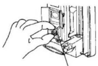
Press and slide the Detection Length Adjustment Switch to the desired position.
natural_image
Line drawing of a hand inserting a small component into a device (no text or symbols)Detection Length Adjustment Switch

Side view of detection pattern

Length of Lower Detection Area decides detection length
The upper detection area stays parallel to the ground at all time. The lower detection area moves as shown above depending on the switch position. So, length of the detection is limited by the length of lower detection area, since both upper & lower detection area have to be blocked at the same time to activate the sensor.

line
| Position (ft) | Value | | ------------- | --------- | | 0 | 1m (3.3ft)| | 5 | ~2.5 | | 10 | ~3.5 | | 15 | ~4.5 | | 20 | ~5.5 | | 25 | ~6.5 | | 30 | ~7.5 | | 35 | ~8.5 | | 40 | ~9.5 | | 45 | ~10.5 | | 50 | ~11.5 |
line
| Position (ft) | Value | | ------------- | --------- | | 0 | 3.3 |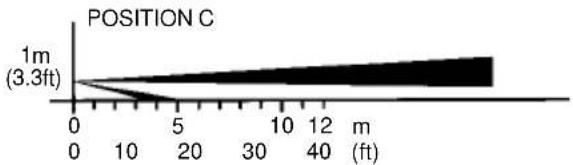
line
| Position (ft) | Value | | ------------- | --------- | | 0 | 3.3 |
line
| Position D | Value | | ---------- | --------- | | 1m (3.3ft) | 3.3 |IMPORTANT
BOTH DETECTION AREA MUST BE BLOCKED FOR DETECTON


Detection Length setting chart Instration Height=1m(3.3ft)
| POSITION | MAX DETECTION LENGTH | |
| Standard | * | |
| A | 12.0 10.0 - (40.0) (33.3) | 15.0 - 50.0) |
| B | 8.0 6.0 - 10.0(26.7) (20.0) | 10.0 - 33.3) |
| C | 5.0 4.0 - 5.5(16.7) (13.3) | 5 - 18.3) |
| D | 2.0 1.5 - 2.5(6.7) (5.0 - 8.3) | 2.5 - 8.3) |
m (ft)
*The maximum detection length may vary as above due to environmental thermal conditions.
IMPORTANT
If there is a traffic near the detection area, please adjust detection 1.5m to 2.0m(5ft to 7ft) away from movements.
(See section 8 OPERATION TEST on page 13 for the details.)
6-2.Area Angle Adjustment

other
| Angle (°) | Distance (ft) | | --------- | ------------- | | 0 | 0 | | 45 | 12 | | 90 | 30 | | 145 | 45 | | 190 | 60 | | 245 | 75 | | 300 | 90 | | 355 | 105 | | 410 | 120 | | 465 | 135 | | 520 | 150 | | 575 | 165 | | 630 | 180 | | 685 | 195 | | 740 | 210 | | 795 | 225 | | 850 | 240 | | 905 | 255 | | 960 | 270 | | 1015 | 285 | | 1070 | 300 | | 1125 | 315 | | 1180 | 330 | | 1235 | 345 | | 1290 | 360 | | 1345 | 375 | | 1400 | 390 | | 1455 | 405 | | 1510 | 420 | | 1565 | 435 | | 1620 | 450 | | 1675 | 465 | | 1730 | 480 | | 1785 | 495 | | 1840 | 510 | | 1895 | 525 | | 1950 | 540 | | 2005 | 555 | | 2060 | 570 | | 2115 | 585 | | 2170 | 600 | | 2225 | 615 | | 2280 | 630 | | 2335 | 645 | | 2390 | 660 | | 2445 | 675 | | 2500 | 690 | | 2555 | 705 | | 2610 | 720 | | 2665 | 735 | | 2720 | 750 | | 2775 | 765 | | 2830 | 780 | | 2885 | 795 | | 2940 | 810 | | 2995 | 825 | | 3050 | 840 | | 3105 | 855 | | 3160 | 870 | | 3215 | 885 | | 3270 | 900 | | 3325 | 915 | | 3380 | 930 | | 3435 | 945 | | 3490 | 960 | | 3545 | 975 | | 3600 | 990 | | 3655 | 1005 | | 3710 | 1020 | | 3765 | 1035 | | 3820 | 1050 | | 3875 | 1065 | | 3930 | 1080 | | 3985 | 1095 | | 4040 | 1110 | | 4095 | 1125 | | Note: The angle values are not explicitly labeled in the code. The data is presented in a format with 'Top view' as the index of the chart. There is only one data series in this case. The values for 'Active detection fingers' are not explicitly labeled in the chart.
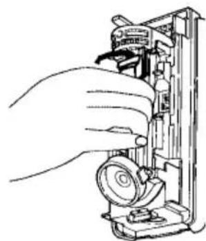
Area angle is 90^ with 7 fingers by 15^ Turn optical cylinder. Angle moves by 15^ per notch.
natural_image
Line drawing of a hand inserting a device into a mechanical housing (no text or symbols)Hold the pyro electric unit and turn it to the desired direction ( 15^ steps).
6-3.Area Masking
natural_image
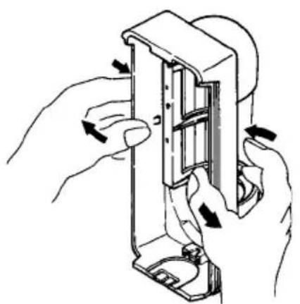
Illustration of hands installing or adjusting a mechanical component with arrows indicating motion (no text or symbols)- Remove the lens holder from the cover as shown above.

natural_image
Technical line drawing of a mechanical component with two views (top and side), no visible text or symbols- Separate the lens from the cover.

natural_image
Technical line drawing of a mechanical component assembly (no text or symbols)- Apply the provided area masking plate to the inside of the lens on the zone to be eliminated.
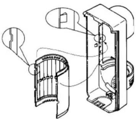
- Put the lens back in by aligning the 4 projections on the cover to the 4 cut outs on the lens. Please do not put the lens up side down.

- Place the lens holder. Confirm the lens holder is held by left and right prongs on the cover.
IMPORTANT
As shown at left, the active detection fingers are always 7, if the area masking plate is not applied.
The active fingers are varied by area adjustment as explained at above.
Before putting the area masking plate to the inside of the lens, make sure which part of the lens will be the detection areas you want to eliminate. There is no effect if you put the plate on the part of the lens which do not cover the detection area.

natural_image
Technical line drawing of a mechanical assembly with no visible text or symbolsSensitivity Select Switch (L,M,H)
When greater sensitivity is desired, select "H". When the installation site is poor (bad conditions) select "L".
6-5. Voice Warning Function Setup (VX-402REC only)
1. Choosing a playback mode
The VX-402REC detector provides several playback modes.(See section7 on page 10-12.)
Choose the desired mode using the voice mode switch.
2. Message selection and recording
Choose and record a message suitable for the function to be used.
For message selection, operate the DIP switch B. (See section 6-6.)
3. Volume adjustment


Adjust the voice volume by turning the adjustment.
4. External speaker
An external speaker may be connected to the VX-402REC detector to thunder the intruder away.
Wiring Diagram

IMPORTANT
- Recommended speaker Impedance : 8 Ω Max powe •r : over 30W Output S.P.L: over 90dB/m Weatherproof
- Speaker with amplifier can not be used.
•Wiring length AWG18(0.83mm²): 10 m
6-6.DIP Switch Setup
VX-402
DETECTABLE DIRECTION:
ALARM OUTPUT:
DIRECTIONAL DETECTION:
DAY/NIGHT MODE:
DIP SWITCH A

ON OFF :LED INDICATOR
:PULSE COUNT
VX-402REC
DETECTABLE DIRECTION:
ALARM OUTPUT:
STATUS SELECT:
DAY/NIGHT MODE:

IMPORTANT
When AUX INPUT is not connected, set as follows.
VX-402
:Set Directional Detection to OFF.
VX-402REC
:Do not set a voice mode switch as Pre-Warning
7.FUNCTIONS
7-1. Two Detectors Mode
The functions of the VX-402 series can be extended by connecting components such as outdoor PIR's, active IR beams or magnetic contacts to the AUX INPUT terminal.
Wiring Diagram
7-1-1. Detection Area Extension Function (DIP switch A-3/Directional Detection:OFF)

Case A=>ALARM
Case B=>ALARM
When the Directional Detection mode is selected OFF:
Alarm signal will be sent to the control panel when either VX-402 series or slave activates.
(In VX-402REC, do not set the voice mode switch as Pre-Warning.)
7-1-2.Directional Detection Function (DIP switch A-3/Directional Detection:ON)
When the Directional Detection mode is selected ON:
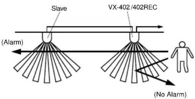
Alarm signal will be sent to the control panel when both VX-402 series and slave activate. In this case, select the direction by the DIP switch A. (See section 6-6 on page 9.)
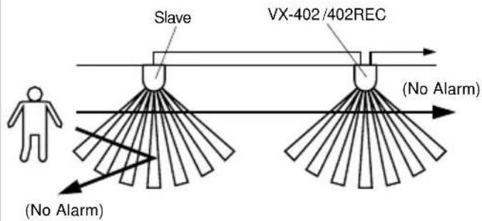
SLAVE -> VX-402 series :
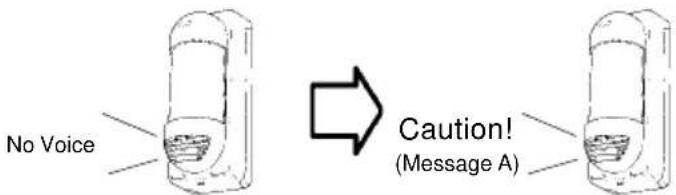
When a person passes the SLAVE area then enters the area covered by the VX-402 series within 1 minute, the VX-402 series will activate.(See page 11.)
VX-402 series -> SLAVE :
When a person passes the VX-402 series area then enters the area covered by the SLAVE unit within 1 minute, the VX-402 series will activate. (See page 11.)

Voice Mode Switch
In VX-402REC, set the voice mode switch as Pre-Warning.
VX-402/402REC

VX-402REC
When it passes along the area of slave.
When it passes along the area of VX-402REC.

VX-402RECVX-402/402REC

When it passes along the area of VX-402REC.
When it passes along the area of slave.
VX-402 series -> SLAVE :
VX-402/402REC
flowchart
graph TD
    A["Human"] --> B["Slave"]
    B --> C["VX-402/402REC"]
    C --> D["(No Alarm)"]
    style A fill:#f9f,stroke:#333
    style B fill:#ccf,stroke:#333
    style C fill:#cfc,stroke:#333
    style D fill:#fcc,stroke:#333
VX-402REC
When it passes along the area of slave.
When it passes along the area of VX-402REC.
VX-402RECVX-402/402REC

When it passes along the area of VX-402REC.
When it passes along the area of slave.
IMPORTANT
- During the Direction Detection mode is set ON, the alarm occurs only when the detector which set as second-detection detects the moving object. If the second-detection detector doesn't detect the anything within 60 seconds after the first alarm occurred, the alarm is reset.
- In case the VX series are used for both master and slave unit, use the slave unit with following setting mode. VX-402 : Set the Direction Detection mode OFF. VX-402REC : Do not set the voice mode switch as a pre-warning mode.
7-2.Day/Night Message Mode (VX-402REC only)
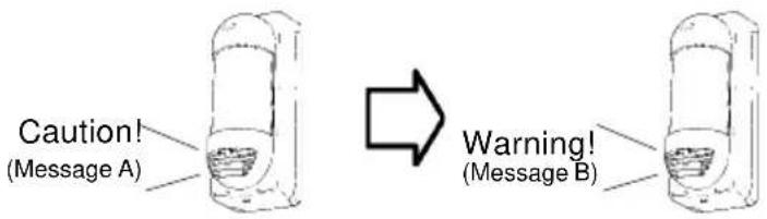
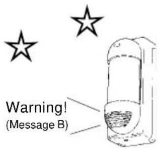
The detector will automatically change messages from that for the daytime to that for the night-time and vice versa.
Daytime : Message A
Night-time: Message B


7-3.Arm/Disarm Mode (VX-402REC only)
The detector will sound different messages when it is set for the armed mode or disarmed mode.
Armed : Message A
Disarmed: Message B


Voice Mode Switch

flowchart
graph TD
    A["Non-Voltage Contact Control Voltage Control"] --> B["Wiring between Power(-) and Voice Contorol Input Wiring to PGM Programmable Output"]
    C["Control Panel"] --> D["Non-Voltage Contact Output"]
    C --> E["Power(-) Voice Contorol Input Voice Contorol Input"]
    F["Control Panel"] --> G["PGM Output"]
| Detector SettingControl Panel | +ARM | -ARM | ||
| Non-Voltage Contact Control | Voltage Control | Non-Voltage Contact Control | Voltage Control | |
| Armed | OPEN | DC 5 - 18V | CLOSE | DC 0 - 1V |
| Disarmed | CLOSE | DC 0 - 1V | OPEN | DC 5 - 18V |
7-4. Sequential Message Mode (VX-402REC only)
In case, the detector detects the moving object 3 times within 30 seconds during the Sequential Message mode is set ON, the message is automatically changed from 3^rd time detection.
1^st and 2^nd time detection (within 30 seconds): Message A
3 ^rd time detection (within 30 seconds) : Message B

8. OPERATION TEST
- Turn LED indicator on. (See page 9.)
- Check and adjust the detection area. (See pages 7,8.)

natural_image
Simple line drawing of a person standing near a beam with light rays, no text or symbols presentIMPORTANT!
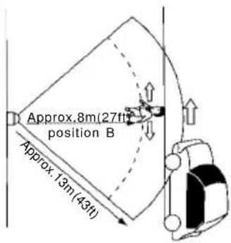
1) When the car or person goes near the detection area (a), please adjust the detection area 1.5m to 2m (5ft to 7ft) shorter than movement area (b) and confirm by walk test. Because, the actual detection area may change from 1.5m to 2m (5ft to 7ft) due to the environmental thermal conditions.

The detection area might increase when there is a big temperature difference between the moving object and the background.
Example
When around 13m (43ft) detection area is required as shown below.
1) If the detection length adjusted to position A[12m (40ft)], there is a possibility to detect the car, depending on the environmental thermal conditions.

In such case,
1) Please adjust the detection length to position B. The detection length will be around 8m (27ft) which is rather shorter than ideal length but can remove the chance of false detection.
2) Confirm by walk test. Detects at area a and no detection at area b.

2)VX-402 has a multi-level detection pattern (from side view). A heat source beyond the detection area may cause the detector a false alarm by reflecting off the ground. Examples of reflective ground is water (puddle), wet road, smooth surface concrete and asphalt road. Reflection rate is not 100% of course on the ground, however, if the heat source is strong and / or reflection rate is high, detectors detection distance will be longer than required and may detect unwanted objects beyond. According to the ground condition of the installation site, select the detection range position.

natural_image
Simple line drawing of a person standing near a vertical barrier with diagonal lines (no text or symbols)9.TROUBLE SHOOTING
| PROBLEM | DESCRIPTION PROBABLE CAUSE REMEDY | ||
| Detector fails to work. | Incorrect power supply voltage. Set supply voltage | for a range of 9.5 to 18 VDC. | |
| LED does not light. LED | switch is turned OFF. | Turn LED switch ON.(See section 6-6 on page 9.) | |
| Alarm is not outputted. | DIP switch A-4 is set for Night Only. | Set switch A-4 for Day/Night and see if it works.(See section 6-6 on page 9.) | |
| DIP switch A-3 (Directional Detection) is turned ON. | Turn OFF DIP switch A-3.(See section 6-6 on page 9.) | ||
| Faulty wiring to detector. | Rewire alarm output correctly.(See section 4 on page 5.) | ||
| LED blinks continuously | Incorrect power supply voltage. Set supply voltage | for a range of 9.5 to 18 VDC. | |
| Make alarm continuously | Jumper is not connected to the AUX INPUT terminal. | Connect the jumper to the terminal.(See section 4 on page 5.) | |
| Make alarms even though no moving object is in the area | Detector is not installed perpendicularly to the ground. | Reinstall the detector perpendicularly to the ground. (See section3-2 on page 4.) | |
| Lower detection area is unnecessarily long. | Confirm and reset the detection area.(See section6-1,2 on page 7,8.) | ||
| Lower detection area receives reflected sunlight or car light, etc. | Remove the reflector or reset the detection area or mask the area exposed to reflected light.(See section6-1 - 3 on page 7,8.) | ||
| Lower detection area is exposed to direct sunlight or car light. | Reset the area so it may not receive direct light.(See section6-1,2 on page 7,8.) | ||
| There is any heat source (stove or heater, etc.) in the area that may cause temperature change. | Reset the area or remove the heat source.(See section6-1,2 on page 7,8.) | ||
| There is any moving object (laundry on clothesline, plants, etc.) in the area. | Reset the area or remove moving objects.(See section6-1,2 on page 7,8.) | ||
| No detection occasionally | Detection area is not set appropriately. | Reset the area appropriately.(See section6-1,2 on page 7,8.) | |
| Sensitivity is set for L(ow). | Reset sensitivity for M(edium) or H(igh).(See section 6-4 on page 9.) | ||
| PROBLEM | DESCRIPTION PROBABLE | CAUSE REMEDY | |
| No message output. | No message at all. | Volume controller is set for Low. | Reset volume for an appropriate level.(See section 6-5 on page 9.) |
| Voice control input is not wired correctly. | Wire the voice control input correctly.(See section 4 on page 5.) | ||
| Set DIP switch B-3 (Message A) and DIP switch B-4 (Message B) for PAUSE. | Set DIPswitch B-3 and DIP switch B-4for ACTIVE.(See section 6-6 on page 9.) | ||
| Message A not displayed. | Set DIP switch B-3 for PAUSE. | Set DIP switch B-3 for ACTIVE.(See section 6-6 on page 9.) | |
| Message B not displayed. | Set DIP switch B-4 for PAUSE. | Set DIP switch B-4 for ACTIVE.(See section 6-6 on page 9.) | |
| No message come out. | Too much noise is applied to power supply. | Move the detector from the noise source asmuch as possible. | |
| Recording fails. | Microphone dead. | Recording volume controller is not set for Max and recording level indicator does not blink during recording. | Set the controller for Max and make sure that the indicator blinks during recording.(See section 5-2 on page 6.) |
| External sound sourse dead. | Connection cable is not suitable for monaural recording. | Use a monaural connection cable to connect the Detector to the earphone or headphone jack of th sound source. Also, make sure that the indicator blinks during recording.(See section 5-1,2 on page 6.) | |
| Cable is not connected to the earphone or headphone jack. | |||
| Recording level indicator does not blink during recording. | |||
| All recording functions dead. | Both DIP switch B-3 and B-4 are set for ACTIVE or PAUSE. | Set either Track A (DIP switch B-3) or Track B (DIP switch B-4) for ACTIVE.Also, make sure that the indicator blinks during recording.(See section 5-1 on page 6.) | |
| Message A fails to record. | Not only DIP switch B-3 but also B-4 is set for ACTIVE. | Set only DIP switch B-3 (Message A) for ACTIVE.(See section 6-6 on page 9.) | |
| Message B fails to record. | Not only DIP switch B-4 but also B-3 is set for ACTIVE. | Set only DIP switch B-4 (Message B) for ACTIVE.(See section 6-6 on page 9.) | |
10.SPECIFICATIONS
| MODEL VX-402 VX-402REC | ||
| Detection Method Passive Infrared | ||
| Coverage 12m(40ft)90° wide | ||
| Detection Zones 14zones | ||
| Mounting Height 0.8-1.2m(2.7-4ft) | ||
| Sensitivity | 2.0°C(3.6°F) at 0.6m/s | |
| Detectable Speed 0.3-1.5m/s(1-5ft/s) | ||
| Power Input 9.5-18VDC | ||
| Current Draw | NC Normal 25mA Max 28mA Normal 25mA | Max 180mA |
| NO Normal 10mA Max 35mA Normal 12mA | Max 200mA | |
| Alarm Period 2±1sec | ||
| Alarm Output Selectable N.C./N.O.; 28VDC 0.2A Max | ||
| Tamper Switch | N.C. Opens when cover removed | |
| Pulse Count | 20±5sec 2 or 4 | |
| Warm-up Period | Approx 30sec(LED blinks) | |
| LED Indicator | LED blinking during warm-up periodAlarm conditionRecording condition | |
| Weatherproof | IP54 | |
| Operating Temperature | -20 - +50°C(-4 - +122°F) | |
| Environment Humidity | 95% Max | |
| RF Interference | No Alarm 30V/m | |
| Mounting | Wall, Pole, Conduit and Electric box | |
| Weight 550g(19.4oz) | ||
| Accessories | Pole mount kit, Screw Kit, Area Masking Plate | |
Note: Specifications and design are subject to change without prior notice.
11.DIMENSIONS

NOTE
This unit is designed to detect movement of an intruder and activate an alarm control panel.
Being only a part of a complete system, we cannot accept responsibility for any damages or other consequences resulting from an intrusion.
This Product conforms to the EMC Directive.89/336 EEC.

OPTEX
OPTEX CO., LTD. (ISO 9001 Certified by LRQA)
4-7-5 Nionohama Otsu, 520-0801 Japan
TEL (077)524-6047 FAX (077)522-9022
OPTEX INCORPORATED
1845W. 205th Street Torrance, CA 90501-1510 U.S.A.
TEL (310)533-1500 FAX (310)533-5910
OPTEX (EUROPE) LTD. (ISO 9002 Certified by NQA)
Clivemont Road, Cordwallis Park, Maidenhead, Berkshire, SL6 7BU U.K.
TEL (01628)631000 FAX (01628)636311



- Standard model Voice Warning model
- FEATURES
- YEAR WARRANTY
- CONTENTS
- Safety-Related Precautions
- INSTALLATION HINTS
- 2.DESCRIPTION AND OPERATION
- 3.INSTALLATION
- 3-1.Before the Installation
- 3-2. Wall Mount
- IMPORTANT
- Surface wiring
- Upper Knockout Wiring Hole (b) Lower Knockout Wiring Hole
- 3-3.Pole Mount
- 3-4. Electric Box Mount
- 4.WIRING
- VX-402
- VX-402REC
- 5.RECORDING
- 5-1.Description for Recording
- 5-2. Recording Method
- 6.SETTING & ADJUSTMENTS
- 6-1. Detection Length Adjustment
- Length of Lower Detection Area decides detection length
- 6-2.Area Angle Adjustment
- 6-3.Area Masking
- 6-5. Voice Warning Function Setup (VX-402REC only)
- Choosing a playback mode
- Message selection and recording
- Volume adjustment
- External speaker
- 6-6.DIP Switch Setup
- DIP SWITCH A
- 7.FUNCTIONS
- 7-1. Two Detectors Mode
- 7-1-1. Detection Area Extension Function (DIP switch A-3/Directional Detection:OFF)
- 7-1-2.Directional Detection Function (DIP switch A-3/Directional Detection:ON)
- 7-2.Day/Night Message Mode (VX-402REC only)
- 7-3.Arm/Disarm Mode (VX-402REC only)
- 7-4. Sequential Message Mode (VX-402REC only)
- OPERATION TEST
- IMPORTANT!
- Example
- NOTE
Brand : OPTEX
Model : VX-402REC
Category : Motion detector