5150A-T - Server Moxa - Free user manual and instructions
Find the device manual for free 5150A-T Moxa in PDF.


| Product Type | Industrial Server |
| Brand | Moxa |
| Model | 5150A-T |
| Form Factor | 1U Rackmount |
| Dimensions (W x D x H) | 440 x 400 x 44 mm |
| Weight | Approx. 10 kg |
| Power Supply | 100-240 V AC, 50/60 Hz |
| Power Consumption | 200 W (typical) |
| Processor | Intel Xeon or equivalent |
| Memory | Up to 64 GB DDR4 ECC |
| Storage | 2 x 2.5" SATA/SAS bays |
| Network Interfaces | 2 x Gigabit Ethernet |
| Operating System | Linux/Windows Server compatible |
| Operating Temperature | -10°C to 60°C |
| Storage Temperature | -20°C to 80°C |
| Humidity | 5% to 95% (non-condensing) |
| Certifications | CE, FCC, UL |
| Cooling | 2 x 40mm fans |
| Mounting | Rackmount kit included |
| Warranty | 3 years limited |
Frequently Asked Questions - 5150A-T Moxa
User questions about 5150A-T Moxa
0 question about this device. Answer the ones you know or ask your own.
Ask a new question about this device
Download the instructions for your Server in PDF format for free! Find your manual 5150A-T - Moxa and take your electronic device back in hand. On this page are published all the documents necessary for the use of your device. 5150A-T by Moxa.
USER MANUAL 5150A-T Moxa
NPort 5100A Series Users Manual
Edition 4.1, August 2016
www.moxa.com/product
MOXA®
© 2016 Moxa Inc. All rights reserved.
NPort 5100A Series Users Manual
The software described in this manual is furnished under a license agreement and may be used only in accordance with the terms of that agreement.
Copyright Notice
© 2016 Moxa Inc. All rights reserved.
Trademarks
The MOXA logo is a registered trademark of Moxa Inc.
All other trademarks or registered marks in this manual belong to their respective manufacturers.
Disclaimer
Information in this document is subject to change without notice and does not represent a commitment on the part of Moxa.
Moxa provides this document as is, without warranty of any kind, either expressed or implied, including, but not limited to, its particular purpose. Moxa reserves the right to make improvements and/or changes to this manual, or to the products and/or the programs described in this manual, at any time.
Information provided in this manual is intended to be accurate and reliable. However, Moxa assumes no responsibility for its use, or for any infringements on the rights of third parties that may result from its use.
This product might include unintentional technical or typographical errors. Changes are periodically made to the information herein to correct such errors, and these changes are incorporated into new editions of the publication.
Technical Support Contact Information
www.moxa.com/support
Moxa Americas
Toll-free: 1-888-669-2872
Tel: +1-714-528-6777
Fax: +1-714-528-6778
Moxa Europe
Tel: +49-89-3 70 03 99-0
Fax: +49-89-3 70 03 99-99
Moxa India
Tel: +91-80-4172-9088
Fax: +91-80-4132-1045
Moxa China (Shanghai office)
Toll-free: 800-820-5036
Tel: +86-21-5258-9955
Fax: +86-21-5258-5505
Moxa Asia-Pacific
Product Features 1-2
Product Specifications 1-3
2. Getting Started 2-1
Panel Layouts....2-2
NPort 5110A, NPort 5130A, NPort 5150A....2-2
NPort P5150A 2-3
Connecting the Hardware 2-3
Connecting the Power 2-3
NPort P5150A....2-3
NPort 5150A/5130A/5150A....2-3
Connecting to the Network 2-4
Connecting to a Serial Device 2-4
LED Indicators 2-4
Adjustable Pull High/Low Resistor for the RS-485 Port 2-4
NPort 5130A/5150A Jumpers....2-5
NPort P5150A....2-6
3. Initial IP Address Configuration.... 3-1
Initializing the NPort 5100A's IP Address ....3-2
Factory Default IP Address....3-2
NPort Administration Suite 3-2
ARP 3-3
Telnet Console 3-4
Serial Console (19200, n, 8, 1) (NPort 5110A/5150A/P5150A only) 3-6
4. Choosing the Proper Operation Mode 4-1
Overview 4-2
Real COM Mode 4-2
RFC 2217 Mode....4-3
TCP Server Mode 4-3
TCP Client Mode 4-3
UDP Mode....4-4
Pair Connection Mode....4-4
Ethernet Modem Mode....4-4
Reverse Telnet Mode....4-5
Disabled Mode....4-5
5. Web Console Configuration 5-1
Opening Your Browser....5-2
Quick Setup 5-4
Export/Import 5-6
Basic Settings 5-6
Network Settings 5-7
SNMP Settings 5-9
IP Address Report 5-9
Serial Settings....5-10
Serial Parameters 5-11
Operating Settings....5-12
Real COM Mode....5-12
RFC 2217 Mode....5-15
TCP Server Mode....5-16
TCP Client Mode 5-19
UDP Mode 5-23
UDP Multicast 5-25
Pair Connection Mode 5-25
Pair Connection Master Mode....5-25
Pair Connection Slave Mode 5-26
Ethernet Modem Mode 5-26
Dial-in 5-27
Dial-out 5-27
Disconnection Request from the Local Site 5-27
Disconnection Request from the Remote Site 5-27
AT Commands 5-28
S Registers....5-29
Reverse Telnet Mode 5-29
Disabled Mode 5-30
Accessible IP Settings 5-31
Auto Warning Settings....5-32
Auto warning: Email and SNMP trap 5-32
Mail Server 5-32
SNMP Trap Server 5-33
Event Type 5-33
DCD changed 5-34
DSR changed....5-34
Upgrade Firmware 5-34
Monitor 5-35
Monitor Line 5-35
Monitor Async 5-35
Monitor Async-Settings 5-36
Change Password 5-36
Load Factory Default 5-37
- Configuring NPort Administrator.... 6-1
Overview 6-2
Installing NPort Administrator 6-2
Configuration 6-5
Broadcast Search 6-5
Unlock Password Protection 6-6
Configuring the NPort 5100A 6-8
Upgrading the Firmware....6-9
Export Configuration....6-10
Import Configuration 6-10
Monitor 6-11
Initiating the Monitor Function 6-11
Using the Monitor Function 6-11
Port Monitor....6-14
COM Mapping....6-15
Creating a COM Group 6-20
Deleting a COM Group 6-22
Adding a Port to a COM Group 6-23
Removing a Port from a COM Group 6-24
Modify Ports in a COM Group 6-25
Changing the COM Number of a COM Group 6-25
Changing Advanced Settings and Serial Parameters of the COM Group 6-27
Changing the Serial Port Specified as Signal Port for the COM Group 6-28
IP Address Report 6-29
- IP Serial LIB....7-1
Overview 7-2
What is IP Serial Library? 7-2
Why Use IP Serial Library? 7-2
How to Install IP Serial Library....7-2
IP Serial LIB Function Groups....7-3
Sample Program....7-3
A. Pinouts and Cable Wiring ...... A-1
Port Pinout Diagrams ......A-2
Ethernet Port Pinouts....A-2
NPort 5110A Serial Port Pinouts ......A-2
DB9 Male RS-232 Port Pinouts for NPort 5110A ......A-2
NPort 5130A Serial Port Pinouts ......A-2
DB9 Male RS-422/485 Port Pinouts for the NPort 5130A ......A-2
NPort 5150A/P5150A Serial Port Pinouts ......A-3
DB9 Male RS-232/422/485 Port Pinouts for the NPort 5150A....A-3
Cable Wiring Diagrams....A-3
Ethernet Cables A-3
B. Well Known Port Numbers ...... B-1
C. SNMP Agents with MIB II & RS232/422/485 Link Groups C-1
RFC1213 MIB-II Supported SNMP Variables ......C-1
RFC1317: RS-232/422/485 MIB Objects....C-2
D. Auto IP Report Protocol ....D-1
Auto IP Report Format......D-1
Info [n] D-1
ID List......D-2
AP ID & Hardware ID Mapping Table D-2
E. Compliance Notice.... E-1
Federal Communications Commission Statement....E-1
The NPort 5100A and NPort 5100A-T are advanced, 1-port RS-232/422/485 serial device servers with low power consumption and full surge protection.
The following topics are covered in this chapter:
Overview
□ Package Checklist
□ Product Features
□ Product Specifications
Overview
NPort 5100A series device servers, which include the NPort 5110A, 5130A, 5150A, and P5150A, are designed to make your industrial serial devices Internet ready instantly. The compact size of NPort 5100A device servers makes them the ideal choice for connecting your RS-232/422/485 serial devices, such as card readers and payment terminals, to an IP-based Ethernet LAN, making it possible for your software to access serial devices located anywhere on a local LAN, or the Internet.
The NPort 5100A supports several operation modes, including TCP Server, TCP Client, UDP Server/Client, Pair Connection, and Ethernet Modem, ensuring the compatibility of network software that uses a standard network API (Winsock, BSD Sockets). In addition, NPort's Real COM / TTY drivers allow you to set up your COM/TTY port software to work over a TCP/IP network in no time. This excellent feature preserves your software investment and lets you enjoy the benefits of networking your serial devices instantly.
NPort 5100A device servers support automatic IP configuration protocols (DHCP, BOOTP) and manual configuration via the handy web browser console. Both methods ensure quick and effective installation. And with NPort 5100A's Windows Utility, installation is very straightforward, since all system parameters can be stored and then copied to other device servers simultaneously.
Package Checklist
The NPort 5100A Series products are shipped with the following items:
Standard Accessories
• 1 NPort 5100A serial device server
- Quick Installation Guide
- 4 stick-on pads
• Document & Software CD
• Product Warranty Statement
Optional Accessories
• DK-35A DIN-Rail Mounting Kit (35 mm)
- PWR-12150-USJP-SA-T: 100 to 240 VAC input, 12 VDC/1.5A output, -40 to 75°C, screw type, US/JP Plug
- PWR-12150-EU-SA-T: 100 to 240 VAC input, 12 VDC/1.5A output, -40 to 75°C, screw type, EU Plug
- PWR-12150-UK-SA-T: 100 to 240 VAC input, 12 VDC/1.5A output, -40 to 75°C, screw type, UK Plug
- PWR-12150-CN-SA-T: 100 to 240 VAC input, 12 VDC/1.5A output, -40 to 75°C, screw type, CN Plug
- PWR-12150-AU-SA-T: 100 to 240 VAC input, 12 VDC/1.5A output, -40 to 75°C, screw type, AU Plug
NOTE: Notify your sales representative if any of the above items are missing or damaged.
Product Features
The NPort 5100A have the following features:
- Low cost, credit card size
- Makes your serial devices Internet ready
• Easy wall and DIN-Rail mounting
• Real COM / TTY driver for Windows and Linux - Fixed TTY driver for SCO OpenServer, SCO Unixware 7, SCO Unixware 2.1
- Versatile socket operation modes: TCP Server, TCP Client, UDP, and Ethernet Modem
-
Pair Connection mode for connecting two serial devices over a network without a PC
-
Easy-to-use Windows Utility for mass installation
• Auto-detecting 10/100 Mbps Ethernet
• Built-in 15 KV ESD protection for all serial signals
• Supports SNMP MIB-II for network management - Configuration via web/Telnet/serial console
- Configuration utility automatically finds NPort devices on the network
• Supports RFC 2217 and Reverse Telnet modes - IEEE 802.3af compliant PoE (P5150A only)
Product Specifications
Ethernet Interface
Number of Ports: 1
Speed: 10/100 Mbps, auto MDI/MDIX
Connector: 8-pin RJ45
Magnetic Isolation Protection: 1.5 KV built-in
Serial Interface
Number of Ports: 1
Serial Standards:
NPort 5110A: RS-232
NPort 5130A: RS-422/485
NPort 5150A: RS-232/422/485
Connector: DB9 male
Serial Line Protection: 15 KV ESD protection for all signals, Level 1 Surge, EN61000-4-5
RS-485 Data Direction Control: ADDC® (automatic data direction control)
Pull High/Low Resistor for RS-485: 1 KΩ, 150 KΩ
Serial Communication Parameters
Data Bits: 5, 6, 7, 8
Stop Bits: 1, 1.5, 2
Parity: None, Even, Odd, Space, Mark
Flow Control: RTS/CTS and DTR/DSR (RS-232 only), XON/XOFF
Baudrate: 50 bps to 921.6 Kbps
Serial Signals
RS-232: TxD, RxD, RTS, CTS, DTR, DSR, DCD, GND
RS-422: Tx+, Tx-, Rx+, Rx-, GND
RS-485-4w: Tx+, Tx-, Rx+, Rx-, GND
RS-485-2w: Data+, Data-, GND
Software
Network Protocols: ICMP, IP, TCP, UDP, DHCP, BOOTP, Telnet, DNS, SNMP V1, HTTP, SMTP, IGMP V1/2
Configuration Options: Web Console (with new Quick Setup), Serial Console (NPort 5110A/5150A only), Telnet Console, Windows Utility
Windows Real COM Drivers: Windows 95/98/ME/NT/2000, Windows XP/2003/Vista/2008/7/8 x86/x64, 2012 x64
Fixed TTY Drivers: SCO Unix, SCO OpenServer, UnixWare 7, UnixWare 2.1, SVR 4.2, QNX 4.25, QNX 6, Solaris 10, FreeBSD, AIX 5.x, HP-UX 11i, Mac 10.3
Linux Real TTY Drivers: Linux kernel 2.4.x, 2.6.x, 3.x
Physical Characteristics
Housing: Metal
Weight: 340 g
Dimensions:
Without ears: 52 x 80 x 22 mm (2.05 x 3.15 x 0.87 in)
With ears: 75.2 x 80 x 22 mm (2.96 x 3.15 x 0.87 in)
Environmental Limits
Operating Temperature:
Standard Models: 0 to 60°C (32 to 140°F)
Wide Temp. Models: -40 to 75°C (-40 to 167°F)
Storage Temperature: -40 to 75°C (-40 to 167°F)
Ambient Relative Humidity: 5 to 95% (non-condensing)
Power Requirements
Input Voltage: 12 to 48 VDC
Power Consumption:
NPort 5110A: 82.5 mA @ 12 V, 47.3 mA @ 24 V
NPort 5130A: 89.1 mA @ 12 V, 49.5 mA @ 24 V
NPort 5150A: 92.4 mA @ 12 V, 52.8 mA @ 24 V
Standards and Certifications
Safety: UL 60950-1, EN 60950-1
EMC: CE, FCC
EMI: EN 55022 Class A, FCC Part 15 Subpart B Class A
EMS: EN 55024
Power Line Protection:
EN 61000-4-4(EFT) Level 2,
EN 61000-4-5(Surge) Level 3
Reliability
Automatic Reboot Trigger: Built-in WDT (watchdog timer)
MTBF (mean time between failures): 2,231,530 hrs
Warranty
Warranty Period: 5 years
Details: See www.moxa.com/warranty
Patent http://www.moxa.com/doc/operations/Moxa_Patent_Marking.pdf
This chapter includes information about installing the NPort 5100A.
The following topics are covered in this chapter:
□ Panel Layouts
NPort 5110A, NPort 5130A, NPort 5150A
NPort P5150A
□ Connecting the Hardware
Connecting the Power
Connecting to the Network
Connecting to a Serial Device
LED Indicators
Adjustable Pull High/Low Resistor for the RS-485 Port
Panel Layouts
NPort 5110A, NPort 5130A, NPort 5150A
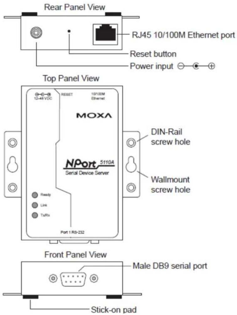
NOTE The layouts of the NPort 5130A and NPort 5150A are the same as the NPort 5110A.
NPort P5150A
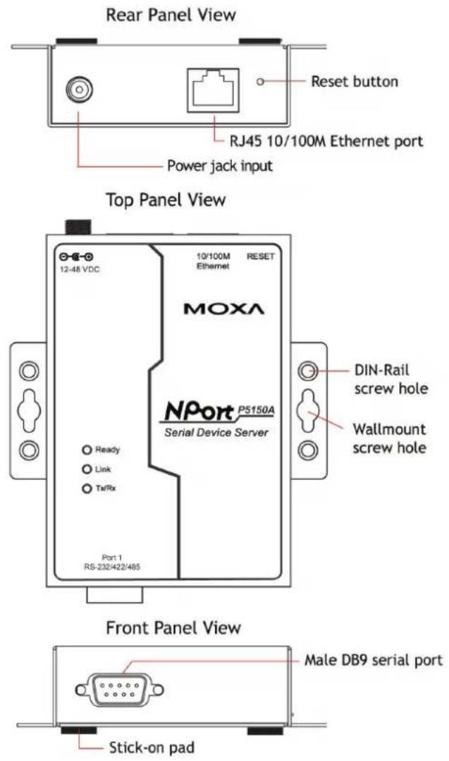
Connecting the Hardware
This section describes how to connect the NPort 5100A to serial devices for first time testing purposes.
Connecting the Power
NPort P5150A
Connect the NPort P5150A's Ethernet port to a PoE switch. The P5150A will receive power from the switch.
NPort 5150A/5130A/5150A
Connect the 12 to 48 VDC power cord to the NPort 5100A's power input. If the power is properly supplied, the "Ready" LED will glow a solid red color until the system is ready, at which time the "Ready" LED will change to a green color.
Connecting to the Network
Connect one end of the Ethernet cable to the NPort 5100A's 10/100M Ethernet port and the other end of the cable to the Ethernet network. The NPort 5100A will indicate a valid connection to the Ethernet in the following ways:
- The Ethernet LED maintains a solid green color when connected to a 100 Mbps Ethernet network.
- The Ethernet LED maintains a solid orange color when connected to a 10 Mbps Ethernet network.
• The Ethernet LED will flash when Ethernet packets are being transmitted or received.
Connecting to a Serial Device
Connect the serial data cable between the NPort 5100A and the serial device. The NPort 5100A's serial port uses the RS-232/422/485 interface to transmit data. The port uses a standard male DB9 pin assignment. Refer to Appendix A for the port's signal definitions.
LED Indicators
The NPort 5100A has 3 LED indicators, as described in the following table.
| LED Name | LED Color | LED Function |
| Ready | Red | Steady on: Power is on and NPort 5100A is booting up. |
| Blinking: Indicates an IP conflict, or DHCP or BOOTP server did not respond properly. | ||
| Green | Steady on: Power is on and the NPort 5100A is functioning normally. | |
| Blinking: The device server has been located by Administrator's Location function. | ||
| Off | Power is off, or power error condition exists. | |
| Link | Orange | The device is connected to a 10 Mbps Ethernet connection. |
| Green | The device is connected to a 100 Mbps Ethernet connection. | |
| Off | The Ethernet cable is disconnected. | |
| Tx/Rx | Orange | The serial port is receiving data. |
| Green The serial port is transmitting data. | ||
| Off | No data is being transmitted or received through the serial port. | |
Adjustable Pull High/Low Resistor for the RS-485 Port
In some critical environments, you may need to add termination resistors to prevent the reflection of serial signals. When using termination resistors, it is important to set the pull high/low resistors correctly so that the electrical signal is not corrupted. Since a particular pull high/low resistor value cannot fit all environments, the NPort 5150A/5130A uses jumpers and the NPort P5150A uses dip switches to set the pull high/low resistor values for each serial port.
NPort 5130A/5150A Jumpers
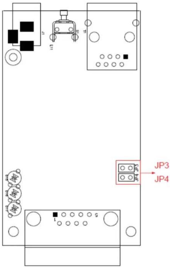
To set a pull high/low resistor to 150 kΩ, make sure that the two jumpers (JP3 and JP4) assigned to the serial port are not shorted by jumper caps. This is the default setting.
To set a pull high/low resistor to 1 kΩ, make sure that the two jumpers (JP3 and JP4) assigned to the serial port are shorted by jumper caps.
NPort P5150A
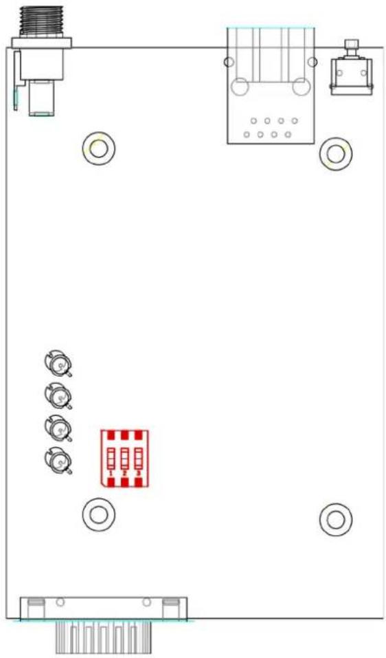
natural_image
Top-down schematic of a device layout with labeled components and a central red circuit board (no text or symbols)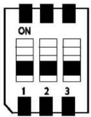
| SW 1 2 3 | |||
| Pull-high resistor | Pull-low resistor | Terminator | |
| ON | 1 kΩ | 1 kΩ | 120 Ω |
| OFF | 150 kΩ* | 150 kΩ* | -* |
* Default

ATTENTION
Do not use the 1 kΩ setting on the NPort 5150A/P5150A when using the RS-232 interface. Doing so will degrade the RS-232 signals and shorten the maximum allowed communication distance.
When setting up your NPort 5100A for the first time, you should first configure the IP address. This chapter introduces the method to configure the device server's IP address. For more details about network settings, see the Network Settings section from Chapter 5, Web Console Configuration.
The following topics are covered in this chapter:
☐ Initializing the NPort 5100A's IP Address
□ Factory Default IP Address
□ NPort Administration Suite
□ ARP
Telnet Console
☐ Serial Console (19200, n, 8, 1) (NPort 5110A/5150A/P5150A only)
Initializing the NPort 5100A's IP Address
- Determine whether your NPort 5100A needs to use a Static IP or Dynamic IP (either DHCP or BOOTP application).
- If the NPort 5100A is used in a Static IP environment, you can use NPort Administration Suite, ARP, Web Console, Telnet Console, or Serial Console to configure the new IP address.
- If the NPort 5100A is used in a Dynamic IP environment, you can use NPort Administration suite, Web Console, Telnet Console, or Serial Console to configure the NPort 5100A to get an IP address dynamically with DHCP, DHCP/BOOTP, or BOOTP.

ATTENTION
Consult your network administrator on how to reserve a fixed IP address for your NPort 5100A in the MAC-IP mapping table when using a DHCP Server or BOOTP Server. In most applications, you should assign a fixed IP address to your NPort 5100A.
Factory Default IP Address
NPort 5100A products are configured with the following default private IP address:
Default IP address: 192.168.127.254
(IP addresses of the form 192.168.xxx.xxx are referred to as private IP addresses, since it is not possible to access a device configured with a private IP address directly from a public network. For example, you would not be able to ping such a device from an outside Internet connection. NPort 5100A applications that require sending data over a public network, such as the Internet, require setting up the server with a valid public IP address, which can be leased from a local ISP.)
NPort Administration Suite
NPort Administration Suite consists of useful utility programs that are used to configure and manage your NPort 5100As.
See Chapter 6 for details on how to install NPort Administration Suite, and how to use this suite of useful utilities to set up IP addresses and configure your NPort 5100A serial device servers.
ARP
You can make use of the ARP (Address Resolution Protocol) command to set up an IP address for your NPort 5100A. The ARP command tells your computer to associate the NPort 5100A's MAC address with the intended IP address. You must then use Telnet to access the NPort 5100A, at which point the device server's IP address will be reconfigured.

ATTENTION
In order to use this setup method, both your computer and the NPort 5100A must be connected to the same LAN. Or, you may use a cross-over Ethernet cable to connect the NPort 5100A directly to your computer's Ethernet card. Your NPort 5100A must be configured with the factory default IP address—192.168.127.254—before executing the ARP command, as described below.
Take the following steps to use ARP to configure the IP address:
- Obtain a valid IP address for your NPort 5100A from your network administrator.
- Obtain the NPort 5100A's MAC address from the label on its bottom panel.
- Execute the 'arp -s' command from your computer's MS-DOS prompt by typing:
arp -s 192.168.200.100 00-90-E8-xx-xx-xx
This is where 192.168.200.100 is the new IP address and 00-90-E8-xx-xx-xx is the MAC address for your NPort 5100A (be sure to use the numbers determined in steps 1 and 2).
- Next, execute a special Telnet command by typing:
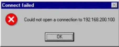
telnet 192.168.200.100 6000
After issuing this command, a Connect failed message will appear, as shown here. After the NPort 5100A reboots, its IP address should be updated to the new address, and you can reconnect using either Telnet, Web, or Administrator to check that the update was successful.
Telnet Console
Depending on how your computer and network are configured, you may find it convenient to use network access to set up your NPort 5100A's IP address. This can be done using Telnet.
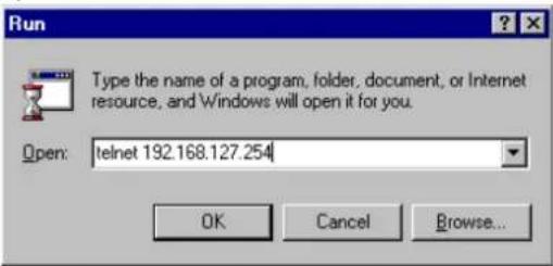
- From the Windows desktop, click Start and then select Run.
- Type telnet 192.168.127.254 (use the correct IP address if different from the default) in the Open text input box, and then click OK.
- When the Telnet window opens, if you are prompted to input the Console password, input the password and then press Enter. Note that this page will only appear if the NPort 5100A is password protected.
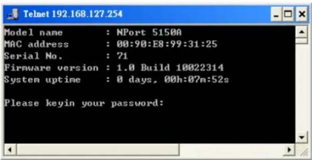
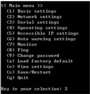
- Type 2 to select Network settings, and then press Enter.
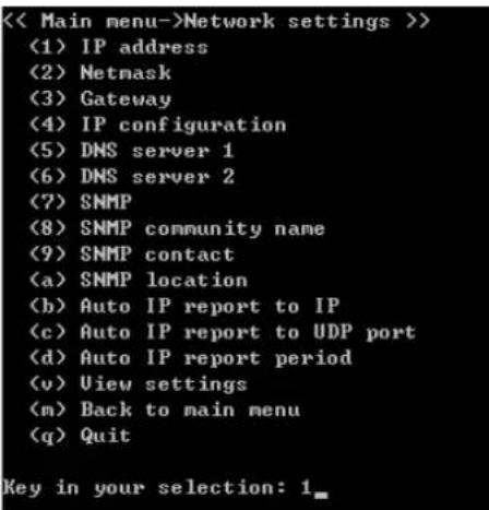
- Type 1 to select IP address and then press Enter.
- Use the Backspace key to erase the current IP address, type in the new IP address, and then press Enter.
<< Main menu->Network settings >>
(1) IP address
(2) Netmask
(3) Gateway
(4) IP configuration
(5) DNS server 1
(6) DNS server 2
(7) SNMP
(8) SNMP community name
(9) SNMP contact
(a) SNMP location
(b) Auto IP report to IP
(c) Auto IP report to UDP port
(d) Auto IP report period
(v) View settings
(m) Back to main menu
(q) Quit

Key in your selection: 1
IP address: 192.168.127.253
- Press any key to continue.
<< Main menu->Network settings >>
(1) IP address
(2) Netmask
(3) Gateway
(4) IP configuration
(5) DNS server 1
(6) DNS server 2
(7) SNMP
(8) SNMP community name
(9) SNMP contact
(a) SNMP location
(b) Auto IP report to IP
(c) Auto IP report to UDP port
(d) Auto IP report period
(v) View settings
(m) Back to main menu
(q) Quit

Key in your selection: 1
IP address: 192.168.127.253
Set IP address success

Press any key to continue...
- Type m and then press Enter to return to the main menu.
<< Main menu->Network settings >>
(1) IP address
(2) Netmask
(3) Gateway
(4) IP configuration
(5) DNS server 1
(6) DNS server 2
(7) SNMP
(8) SNMP community name
(9) SNMP contact
(a) SNMP location
(b) Auto IP report to IP
(c) Auto IP report to UDP port
(d) Auto IP report period
(v) View settings
(m) Back to main menu
(q) Quit

Key in your selection: m.
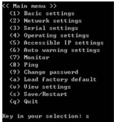
- Type s and then press Enter to Save/Restart the system.
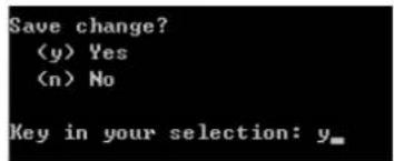
- Type y and then press Enter to save the new IP address and restart the NPort 5100A.
Serial Console (19200, n, 8, 1) (NPort 5110A/5150A/P5150A only)
You may use the RS-232 console port to set up the IP address for an NPort 5100A. We suggest using PComm Terminal Emulator, which is available free of charge as part of the PComm Lite program suite (found on the Software CD that comes with the product), to carry out the installation procedure, although other similar utilities may also be used.
Before you start to configure the NPort 5100A via serial console, turn off the power and connect the serial cable from the NPort 5100A to your computer's serial port.
- Connect the NPort 5100A's serial port 1 directly to your computer's male RS-232/422/485 serial port.
- From the Windows desktop, click Start → Programs → PComm Lite → Terminal Emulator.
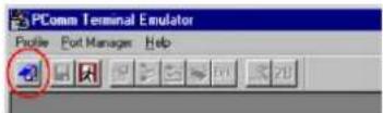
- When the PComm Terminal Emulator window opens, first click on the Port Manager menu item and select Open, or simply click on the Open icon.
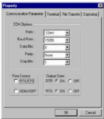
- The Property window opens automatically. From the Communication Parameter page, select the appropriate COM port for the connection, COM1 in this example, and 19200 for Baud Rate, 8 for Data Bits, None for Parity, and 1 for Stop Bits.
- From the Property window's Terminal page, select ANSI or VT100 for Terminal Type and then click OK. If you select Dumb Terminal as the terminal type, some of the console functions—especially the "Monitor" function—may not work properly.
- Press the “” key continuously and then power on the NPort 5100A.

natural_image
Close-up of a standard computer keyboard with a red circle highlighting the leftmost key (no text or symbols visible)- The NPort 5100A will receive the "\"" string continuously and then auto switch from data mode to console mode.
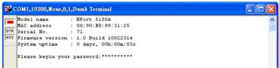
- Input the password when prompted. Note that this page will only appear when the NPort 5100A has been set up for password protection.
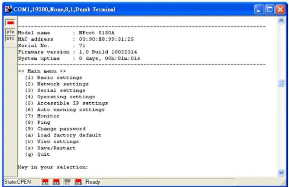
- Start configuring the IP address under Network Settings. Refer to step 4 in the Telnet Console section for the rest of the IP settings.
In this section, we describe the various NPort 5100A operation modes. The options include Real COM Mode, which uses a driver installed on the host computer, and operation modes that rely on TCP/IP socket programming concepts. After choosing the proper operation mode in this chapter, refer to Chapter 5 for detailed configuration parameter definitions.
The following topics are covered in this chapter:
Overview
Real COM Mode
☐ RFC 2217 Mode
TCP Server Mode
□ TCP Client Mode
□ UDP Mode
□ Pair Connection Mode
☐ Ethernet Modem Mode
Reverse Telnet Mode
□ Disabled Mode
Overview
NPort 5100A serial device servers network-enable traditional RS-232/422/485 devices. A serial device server is a tiny computer equipped with a CPU, real-time OS, and TCP/IP protocols that can bi-directionally translate data between the serial and Ethernet formats. Your computer can access, manage, and configure remote facilities and equipment over the Internet from anywhere in the world.
Traditional SCADA and data collection systems rely on serial ports (RS-232/422/485) to collect data from various kinds of instruments. Since NPort 5100A serial device servers network-enable instruments equipped with an RS-232/422/485 communication port, your SCADA and data collection system will be able to access all instruments connected to a standard TCP/IP network, regardless of whether the devices are used locally or at a remote site.
The NPort 5100A is an external IP-based network device that allows you to expand the number of serial ports for a host computer on demand. As long as your host computer supports the TCP/IP protocol, you won't be limited by the host computer's bus limitation (such as ISA or PCI), or lack of drivers for various operating systems.
In addition to providing socket access, the NPort 5100A also comes with a Real COM / TTY driver that transmits all serial signals intact. This means that your existing COM/TTY-based software can be preserved, without needing to invest in additional software.
Three different socket modes are available: TCP Server, TCP Client, and UDP Server/Client. The main difference between the TCP and UDP protocols is that TCP guarantees delivery of data by requiring the recipient to send an acknowledgement to the sender. UDP does not require this type of verification, making it possible to offer speedier delivery. UDP also allows data to be unicast to only one IP address, or multicast to groups of IP addresses.
Real COM Mode
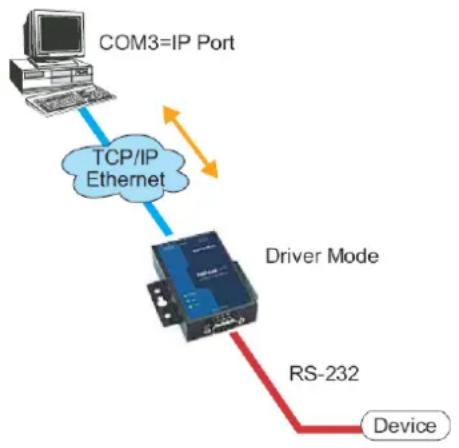
The NPort 5100A comes equipped with COM drivers that work with Windows systems, and also TTY drivers for Linux systems. The driver establishes a transparent connection between host and serial device by mapping the IP:Port of the NPort 5100A's serial port to a local COM/TTY port on the host computer. Real COM Mode also supports up to 4 simultaneous connections, so that multiple hosts can collect data from the same serial device at the same time.
flowchart
graph TD
    A["COM3=IP Port"] -->|TCP/IP Ethernet| B["Driver Mode"]
    B -->|RS-232| C["Device"]
    B -->|TCP/IP Ethernet| A

ATTENTION
The driver used for Real COM Mode is bundled with NPort Administrator. The driver is installed on your computer automatically when you install NPort Administration Suite.
One of the major conveniences of using Real COM Mode is that Real COM Mode allows users to continue using RS-232/422/485 serial communications software that was written for pure serial communications applications. The driver intercepts data sent to the host's COM port, packs it into a TCP/IP packet, and then redirects it through the host's Ethernet card. At the other end of the connection, the NPort 5100A accepts the Ethernet frame, unpacks the TCP/IP packet, and then sends it transparently to the appropriate serial device attached to one of the NPort 5100A's serial ports.

ATTENTION
Real COM Mode allows several hosts to have access control of the same NPort 5100A. The driver that comes with your NPort 5100A controls host access to attached serial devices by checking the host's IP address. Refer to the Accessible IP Settings section of Chapter 5 for more details.
RFC 2217 Mode
RFC 2217 mode is similar to Real COM mode in that a driver is used to establish a transparent connection between a host computer and a serial device by mapping the serial port on the NPort 5100A to a local COM port on the host computer. RFC 2217 defines general COM port control options based on the Telnet protocol. Third party drivers supporting RFC 2217 are widely available on the Internet and can be used to implement Virtual COM mapping to your NPort 5100A serial port(s).
TCP Server Mode
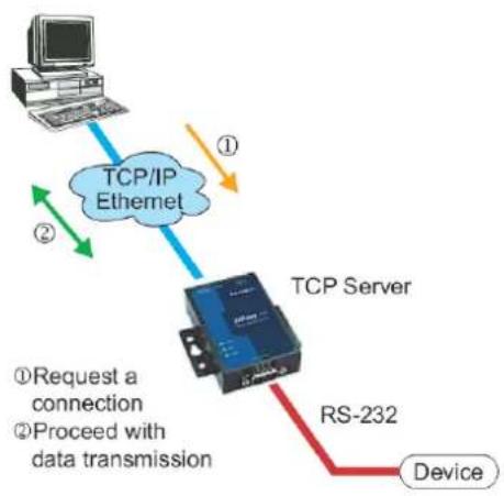
In TCP Server Mode, NPort 5100A is configured with a unique IP:Port combination on a TCP/IP network. In this case, the NPort 5100A waits passively to be contacted by the host computer. After the host computer establishes a connection with the serial device, it can then proceed with data transmission. TCP Server mode also supports up to 4 simultaneous connections, so that multiple hosts can collect data from the same serial device—at the same time. As illustrated in the figure, data transmission proceeds as follows:
- The host requests a connection from the NPort 5100A configured for TCP Server Mode.
- Once the connection is established, data can be transmitted in both directions— from the host to the NPort 5100A, and from the NPort 5100A to the host.
flowchart
graph TD
    A["Computer"] -->|①| B["TCP/IP Ethernet"]
    B -->|②| C["TCP Server"]
    C -->|③| D["RS-232 Device"]
    style A fill:#f9f,stroke:#333
    style B fill:#bbf,stroke:#333
    style C fill:#dfd,stroke:#333
    style D fill:#dfd,stroke:#333
TCP Client Mode
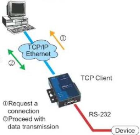
In TCP Client Mode, the NPort 5100A can actively establish a TCP connection with a pre-determined host computer when serial data arrives.
After the data has been transferred, the NPort 5100A can disconnect automatically from the host computer by using the TCP alive check time or Inactivity time settings. Refer to Chapter 5 for detailed configuration instructions. As illustrated in the figure, data transmission proceeds as follows:
- The NPort 5100A configured for TCP Client Mode requests a connection from the host.
- Once the connection is established, data can be transmitted in both directions—from the host to the NPort 5100A, and from the NPort 5100A to the host.
TCP Client Mode
flowchart
graph TD
    A["Computer"] -->|①| B["TCP/IP Ethernet"]
    B -->|②| C["TCP Client"]
    C -->|③| D["RS-232 Device"]
    style A fill:#f9f,stroke:#333
    style B fill:#bbf,stroke:#333
    style C fill:#dfd,stroke:#333
    style D fill:#ffd,stroke:#333
UDP Mode
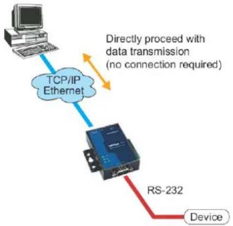
Compared to TCP communication, UDP is faster and more efficient. In UDP mode, you can unicast or multicast data from the serial device to one or multiple host computers, and the serial device can also receive data from one or multiple host computers, making this mode ideal for message display applications.
flowchart
graph TD
    A["Computer"] -->|TCP/IP Ethernet| B["Router"]
    B -->|RS-232 Device| C["Device"]
    note1["Directly proceed with data transmission (no connection required)"]
Pair Connection Mode
Pair Connection Mode employs two NPort 5100A units in tandem, and can be used to remove the 15-meter distance limitation imposed by the RS-232 interface. One NPort 5100A is connected from its RS-232/422/485 port to the COM port of a PC or other type of computer, such as hand-held PDAs that have a serial port, and the serial device is connected to the RS-232/422/485 port of the other NPort 5100A. The two NPort 5100A units are then connected to each other with a cross-over Ethernet cable, both are connected to the same LAN, or in a more advanced setup, they communicate with each other over a WAN (i.e., through one or more routers). Pair Connection Mode transparently transfers both data and modem control signals (although it cannot transmit the DCD signal) between the two NPorts.
Ethernet Modem Mode
Ethernet Modem Mode is designed for use with legacy operating systems, such as MS-DOS, that do not support TCP/IP Ethernet. By connecting one of NPort 5100A's serial ports to the MS-DOS computer's serial port, it is possible to use legacy software originally designed to transmit data via modem, but now transmit the data over the Ethernet.
Reverse Telnet Mode
flowchart
graph TD
    A["Unix"] -->|Telnet| B["Router"]
    C["Windows NT"] -->|TCP/IP| D["Server"]
    D -->|RS-232| B
    B -->|Telnet| C
    style A fill:#f9f,stroke:#333
    style C fill:#f9f,stroke:#333
    style B fill:#ccf,stroke:#333
    style D fill:#ccf,stroke:#333
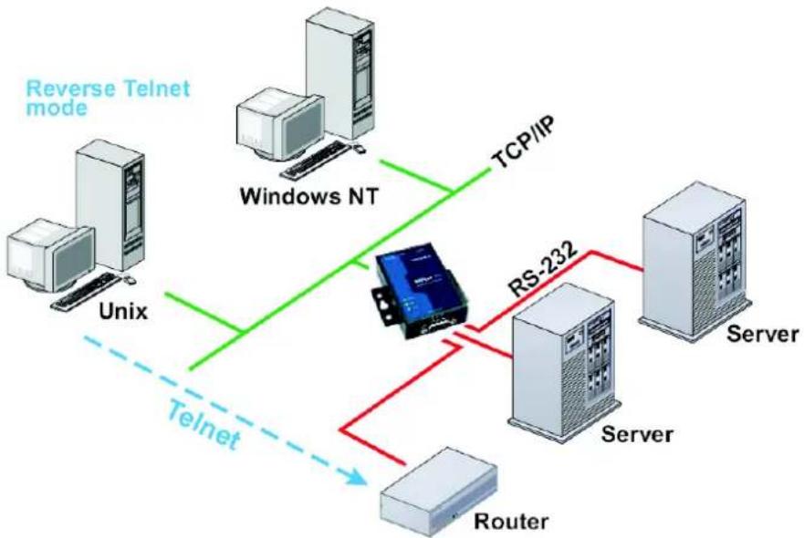
Console management is commonly used by connecting to Console/AUX or COM ports of routers, switches, and UPS units. Rtelnet works the same as TCP Server mode in that only one TCP port is listened to after booting up. The system then waits for a host on the network to initiate a connection. The difference is that the TCP Server mode does not provide the conversion function provided by Telnet. If the connected devices need to use the CR/LF conversion function when controlling, then users must choose Reverse Telnet mode.
Disabled Mode
When the Operation Mode for a particular port is set to Disabled, that port will be disabled.
The Web Console is the most user-friendly method available to configure the NPort 5100A. In this chapter, we introduce the Web Console function groups and function definitions.
The following topics are covered in this chapter:
□ Opening Your Browser
□ Quick Setup
□ Export/Import
□ Basic Settings
□ Network Settings
SNMP Settings
IP Address Report
Monitor
Monitor Line
Monitor Async
➢ Monitor Async-Settings
□ Change Password
□ Load Factory Default
Serial Settings
Serial Parameters
□ Operating Settings
Real COM Mode
RFC 2217 Mode
TCP Server Mode
TCP Client Mode
UDP Mode
▶ UDP Multicast
➢ Pair Connection Mode
Ethernet Modem Mode
Dial-in
Dial-out
➢ Disconnection Request from the Local Site
➢ Disconnection Request from the Remote Site
AT Commands
S Registers
➢ Reverse Telnet Mode
➢ Disabled Mode
□ Accessible IP Settings
□ Auto Warning Settings
➢ Auto warning: Email and SNMP trap
Event Type
□ Upgrade Firmware
Opening Your Browser
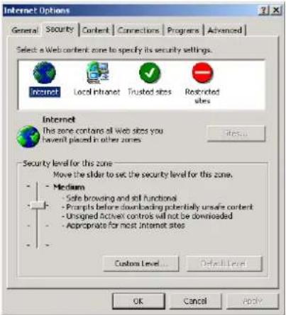
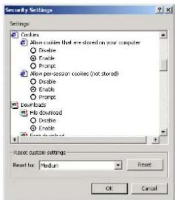
- Open your browser with the cookie function enabled. (To enable your browser for cookies, right click on your desktop Internet Explorer icon, select Properties, click on the Security tab, and then select the three Enable options as shown in the figure below.)
- Type 192.168.127.254 in the Address input box (use the correct IP address if different from the default), and then press Enter.
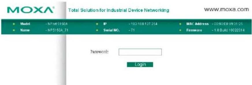
- Input the password if prompted. The password will be transmitted with MD5 encryption over the Ethernet. Note that you will not be prompted to enter the password if the NPort 5100A is not currently password protected.

ATTENTION
If you use other web browsers, remember to Enable the functions to "allow cookies that are stored on your computer" or "allow per-session cookies." NPort 5100A uses cookies only for "password" transmission.

ATTENTION
Refer to Chapter 3, Initial IP Address Configuration, to see how to configure the IP address. Examples shown in this chapter use the Factory Default IP address (192.168.127.254).
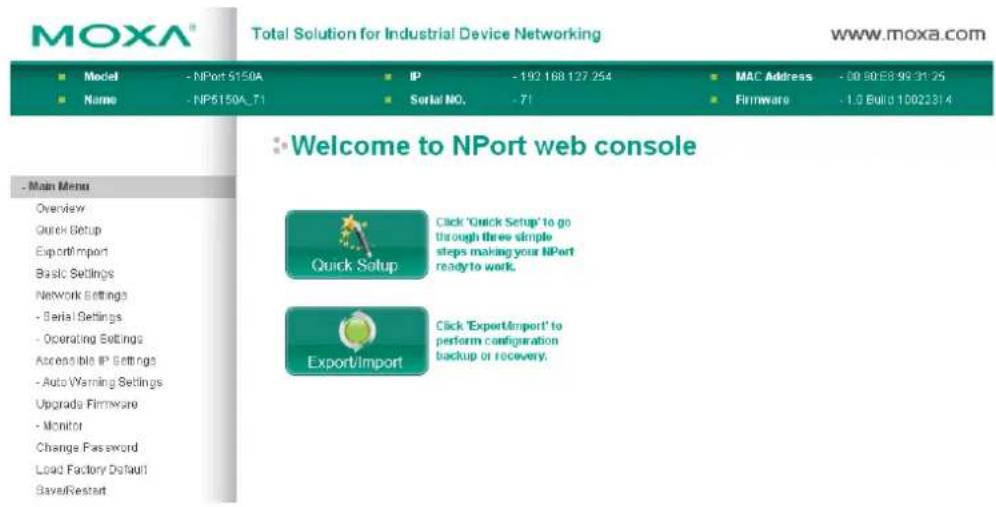
- The NPort 5100A homepage will open next. There are two buttons on this page: Quick setup and Export/Import. You can click Overview at any time to go back to this page. The following sections introduce these two convenient functions and all the other specific settings in the left Main Menu.

ATTENTION
If you can't remember the password, the ONLY way to start configuring the NPort 5100A is to load factory defaults by using the Reset button located near the NPort 5100A's RJ45 Ethernet port.
Remember to export the configuration file when you have finished the configuration. After using the Reset button to load factory defaults, your configuration can be easily reloaded into the NPort 5100A using the Import function.

ATTENTION
If your NPort 5100A application requires using password protection, you must enable the cookie function in your browser. If the cookie function is disabled, you will not be allowed to enter the Web Console Screen.
Quick Setup
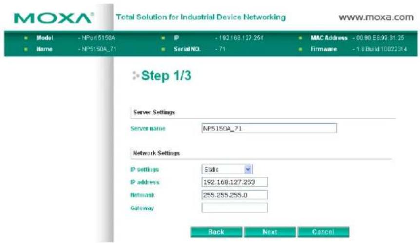
Quick Setup streamlines configuration of your NPort into three basic and quick steps that cover the most commonly-used settings. At any time while in Quick Setup you may click the Back button to return to the previous step, or the Cancel button to reverse all settings. For more detailed settings, please refer to the "Basic Settings," "Network Settings," "Serial Settings," and "Operating Settings," sections later in this chapter.
Step 1/3: In this step, you must assign a valid IP address to the NPort 5100A before it will work in your network environment. Your network system administrator should provide you with an IP address and related settings for your network. In addition, the server name field is a useful way to specify the location or application of different NPort 5100As.
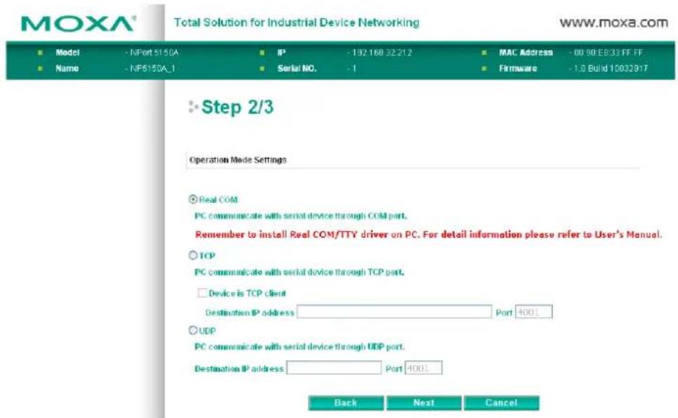
Step 2/3: In this step, you must specify which operation mode you will use. If your operation mode is not Real COM, TCP Server, TCP Client, or UDP mode, click Cancel to return to the main menu and choose Operating Settings to select your proper setting.
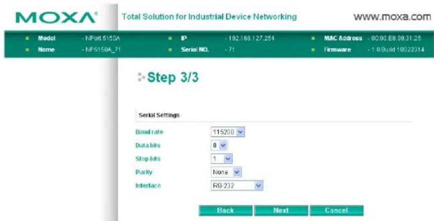
Step 3/3: In this step, you can modify the serial settings.
Review your settings on the Finish Settings page to confirm that they are correct, and then click the Save/Restart button to restart the device with the new settings.
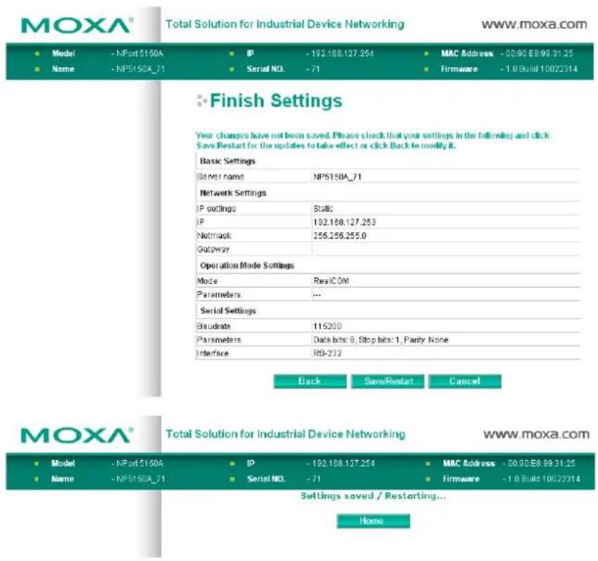
NOTE If you have changed the IP address, you will not be able to return to the Home Page with the Home button.
Export/Import
Export/Import allows you to back up and recover your settings.
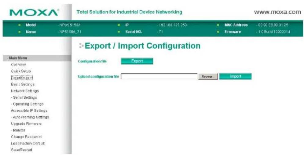
Click Export to store all configuration data into a default file,
Basic Settings
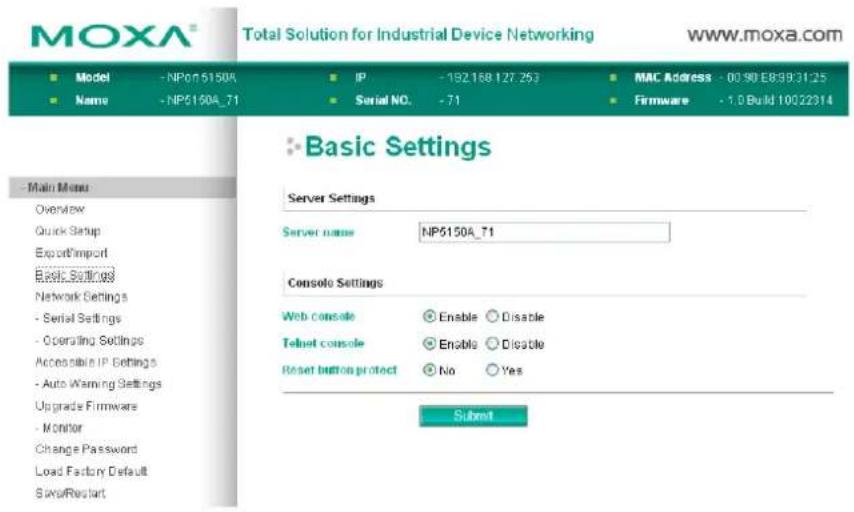
Server name
| Setting | Factory Default | Necessity |
| 1 to 39 characters | NP[model name]_[Serial No.] | Optional |
This option is useful for specifying the location or application of different NPort 5100As.
Web/Telnet Console
The "Disable" option for "Web Console" and "Telnet Console" is included for security reasons. In some cases, you may want to disable one or both of these console utilities as an extra precaution to prevent unauthorized users from accessing your NPort 5100A. The factory default for both Web console and Telnet console is Enable.
Web console
| Setting | Factory Default | Necessity |
| Enable or Disable | Enable | Required |
Telnet console
| Setting | Factory Default | Necessity |
| Enable or Disable | Enable | Required |

ATTENTION
If you disable both the "Web console" and "Telnet console," you can still use NPort Administrator to configure NPort 5100A device servers either locally or remotely over the network. Refer to Chapter 6 for more details.
Reset button protect
| Setting | Factory Default | Necessity |
| No or Yes None Optional |
NOTE: Select the Yes option to allow limited use of the Reset Button. In this case, the Reset Button can be used for only 60 seconds. I.e., 60 seconds after booting up, the Reset Button will be disabled automatically.
Network Settings
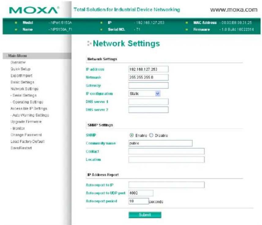
You must assign a valid IP address to the NPort 5100A before it will work in your network environment. Your network system administrator should provide you with an IP address and related settings for your network. The IP address must be unique within the network (otherwise, the NPort 5100A will not have a valid connection to the network). First time users can refer to Chapter 3, Initial IP Address Configuration, for more information.
You can choose from four possible IP Configuration modes Static, DHCP, DHCP/BOOTP, and BOOTP OTndBfigunder the web console screen's IP configuration drop-down box.
IP configuration
| Method Function | Definition |
| Static | User defined IP address, Netmask, Gateway |
| DHCP | DHCP Server assigned IP address, Netmask, Gateway, DNS, and Time Server |
| DHCP/BOOTP | DHCP Server assigned IP address, Netmask, Gateway, DNS, and Time Server, or BOOTP Server assigned IP address (if the DHCP Server does not respond) |
| BOOTP BOOTP Server | ver assigns IP address |
IP address
| Setting | Factory Default | Necessity |
| E.g., 192.168.1.1 (IP addresses of the form x.x.x.0 and x.x.x.255 are invalid.) | 192.168.127.254 Required |
An IP address is a number assigned to a network device (such as a computer) as a permanent address on the network. Computers use the IP address to identify and talk to each other over the network. Choose a proper IP address that is unique and valid in your network environment.
Netmask
| Setting | Factory Default | Necessity |
| E.g., 255.255.255.0 | 255.255.255.0 | Required |
A subnet mask represents all of the network hosts at one geographic location, in one building, or on the same local area network. When a packet is sent out over the network, the NPort 5100A will use the subnet mask to check whether the desired TCP/IP host specified in the packet is on the local network segment. If the address is on the same network segment as the NPort 5100A, a connection is established directly from the NPort 5100A. Otherwise, the connection is established through the given default gateway.
Gateway
| Setting | Factory Default | Necessity |
| E.g., 192.168.1.1 | None | Optional |
A gateway is a network gateway that acts as an entrance to another network. Usually, the computers that control traffic within the network or at the local Internet service provider are gateway nodes. NPort 5100A needs to know the IP address of the default gateway computer in order to communicate with the hosts outside the local network environment. For correct gateway IP address information, consult the network administrator.
IP configuration
| Setting | Factory Default | Necessity |
| Static, DHCP, DHCP/BOOTP, BOOTP | Static | Required |

ATTENTION
In Dynamic IP environments, the firmware will retry 3 times every 30 seconds until network settings are assigned by the DHCP or BOOTP server. The Timeout for each try increases from 1 second, to 3 seconds, to 5 seconds.
If the DHCP/BOOTP Server is unavailable, the firmware will use the default IP address (192.168.127.254), Netmask, and Gateway for IP settings.
DNS server 1 / DNS server 2
| Setting | Factory Default | Necessity |
| E.g., 192.168.1.1 (IP addresses of the form x.x.x.0 and x.x.x.255 are invalid.) | None | Optional |
When the user wants to visit a particular website, the computer asks a Domain Name System (DNS) server for the website's correct IP address, and then the computer uses the response to connect to the web server. DNS is the way that Internet domain names are identified and translated into IP addresses. A domain name is an alphanumeric name, such as moxa.com, that it is usually easier to remember. A DNS server is a host that
translates this kind of text-based domain name into the numeric IP address used to establish a TCP/IP connection.
In order to use the NPort 5100A's DNS feature, you need to configure the DNS server. Doing so allows the NPort 5100A to use a host's domain name to access the host. The NPort 5100A provides DNS server 1 and DNS server 2 configuration items to configure the IP address of the DNS server. DNS Server 2 is included for use when DNS sever 1 is unavailable.
The NPort 5100A plays the role of DNS client, in the sense that the NPort 5100A will actively query the DNS server for the IP address associated with a particular domain name. The NPort 5100A functions that support domain name are Time server, Destination IP Address in TCP Client mode, Mail Server, SNMP trap server, and Auto report to IP.
SNMP Settings
Community name
| Setting | Factory Default | Necessity |
| 1 to 39 characters | public | Optional |
A community name is a plain-text password mechanism that is used to weakly authenticate queries to agents of managed network devices.
Contact
| Setting | Factory Default | Necessity |
| 1 to 39 characters(e.g., Support, 886-89191230 #300) | None Optional |
The SNMP contact information usually includes an emergency contact name and telephone or pager number.
Location
| Setting | Factory Default | Necessity |
| 1 to 39 characters(E.g., Floor 1, office 2) | None Optional |
Specify the location string for SNMP agents such as NPort 5100A. This string is usually set to the street address where the NPort 5100A is physically located.
IP Address Report
When NPort 5100A products are used in a dynamic IP environment, users must spend some time on IP management tasks. For example, if the NPort 5100A works as a server (TCP or UDP), then the host, which acts as a client, must know the IP address of the server. If the DHCP server assigns a new IP address to the NPort 5100A, the host must have some way of determining the NPort 5100A's new IP address.
NPort 5100A products periodically report their IP address to the IP location server in case the dynamic IP has changed. The parameters shown below are used to configure the Auto IP report function. There are two ways to develop an "Auto IP report Server" to receive an NPort 5100A's Auto IP report.
Use Device Server Administrator's IP Address Report function.
"Auto IP report protocol", which can automatically receive the Auto IP report on a regular basis, is also available to help you develop your own software. Refer to Appendix E for the "Auto IP report protocol."
Auto report to IP
| Setting | Factory Default | Necessity |
| E.g., 192.168.1.1 or URL (IP addresses of the form x.x.x.0 and x.x.x.255 are invalid.) | None Optional |
Reports generated by the Auto report function will be automatically sent to this IP address.
Auto report to UDP port
| Setting | Factory Default | Necessity |
| E.g., 4001 4002 Optional |
Auto report period
| Setting | Factory Default | Necessity |
| Time interval (in seconds) | 10 Optional |
Serial Settings
Click Serial Settings, located under Main Menu, to display serial port settings for port 1.
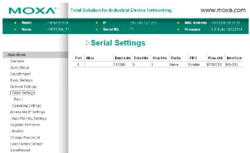
To modify serial settings click Port 1 under Serial Settings, located under Main Menu on the left side of the browser window.
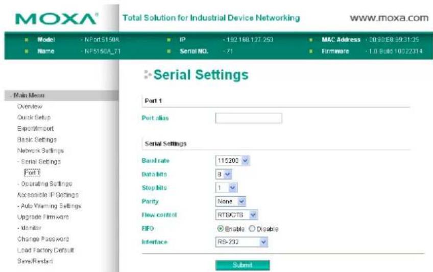
Port alias
| Setting | Factory Default | Necessity |
| 1 to 15 characters (E.g., PLC-No.1) | None Optional |
"Port alias" is included to allow easy identification of the serial devices that are connected to the NPort 5100A's serial port.
Serial Parameters

ATTENTION
Check the serial communication parameters in your Serial Device's user's manual. You should set up NPort 5100A's serial parameters with the same communication parameters used by your serial devices.
Baudrate
| Setting | Factory Default | Necessity |
| 50 bps to 921.6 kbps | 115.2 kbps | Required |
Data bits
| Setting | Factory Default | Necessity |
| 5, 6, 7, 8 8 Required |
When the user sets Data bits to 5 bits, the Stop bits setting will automatically change to 1.5 bits.
Stop bits
| Setting | Factory Default | Necessity |
| 1, 1.5, 2 1 Required |
Stop bits will be set to 1.5 when Data bits is set to 5 bits.
Parity
| Setting | Factory Default | Necessity |
| None, Even, Odd, Space, Mark | None Required |
Flow control
| Setting | Factory Default | Necessity |
| None, RTS/CTS,DTR/DSR, Xon/Xoff | RTS/CTS Required |
FIFO
| Setting | Factory Default | Necessity |
| Enable, Disable | Enable | Required |
NPort 5100A's serial ports provide a 16-byte FIFO both in the Tx and Rx directions. To prevent data loss during communication, disable the FIFO setting when your serial device does not have a FIFO.
Interface
| Setting | Factory Default | Necessity |
| RS-232/422/485 | RS-232(NPort 5110A/5150A /P5150A)RS-422 (NPort 5130A) | Required |
Operating Settings
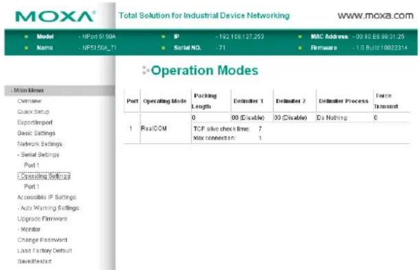
Click Operating Settings, located under Main Menu, to display the operating settings for both of NPort 5100A's serial ports.
Real COM Mode
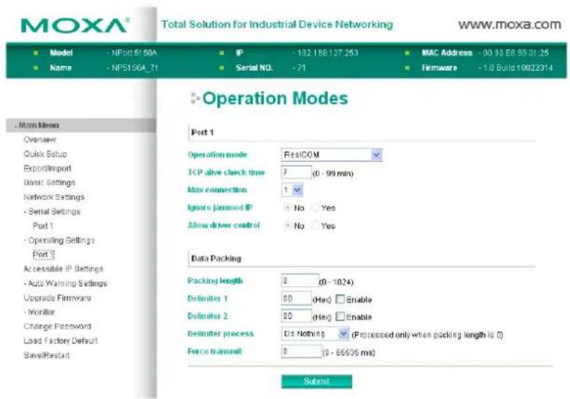
TCP alive check time
| Setting | Factory Default | Necessity |
| 0 to 99 min | 7 min | Optional |
0 min: TCP connection is not closed due to an idle TCP connection.
1 to 99 min: The NPort 5100A automatically closes the TCP connection if there is no TCP activity for the given time. After the connection is closed, the NPort 5100A starts listening for another Real COM driver connection from another host.
Max connection
| Setting | Factory Default | Necessity |
| 1, 2, 3, 4, 5, 6, 7, 8 1 | Required |
Max connection is usually used when the user needs to receive data from different hosts simultaneously. The factory default is 1. In this case, only one specific host can access this port of the NPort 5100A, and the Real COM driver on that host will have full control over the port.
Max. Connection 1: Allows only 1 host's Real COM driver to open the specific NPort 5100A serial port.
Max Connection 2 to 8: Allows 2 to 8 host's Real COM drivers to open the specific NPort 5100A serial port, at the same time. When multiple hosts' Real COM drivers open the serial port at the same time, the COM driver only provides a pure data tunnel without control ability. That is, this serial port parameter will use the firmware's settings, not depend on your application program (AP).
Application software that is based on the COM driver will receive a driver response of "success" when the software uses any of the Win32 API functions. The firmware will only send the data back to the driver on the host.
Data will be sent first-in-first-out when data comes into the NPort 5100A from the Ethernet interface.

ATTENTION
When Max connection > 1, this means that the NPort 5100A will be using a "multi connection application" (i.e., 2 or more hosts are allowed access to the port at the same time). When using a multi connection application, the NPort 5100A will use the serial communication parameters set in the console. All of the hosts connected to that port must use the same serial settings. If one of the hosts opens the COM port with parameters that are different from the NPort 5100A's console setting, data communication may not work properly.
Ignore jammed IP
| Setting | Factory Default | Necessity |
| No or Yes No Optional |
Previously, when Max connections > 1, and the serial device is transmitting data, if any one of the connected hosts is not responding, it will wait until the data has been transmitted successfully before transmitting the second group of data to all hosts. Currently, if you select Yes for "Ignore jammed IP," the host that is not responding will be ignored, but the data will still be transmitted to the other hosts.
Allow driver control
| Setting | Factory Default | Necessity |
| No or Yes No Optional |
If "max connection" is greater than 1, NPort will ignore driver control commands from all connected hosts. However, if you set "Allow driver control" to YES, control commands will be accepted. Note that since the NPort 5100A may get configuration changes from multiple hosts, the most recent command received will take precedence.
Packing length
| Setting | Factory Default | Necessity |
| 0 to 1024 0 Optional |
Default = 0: The Delimiter Process will be followed, regardless of the length of the data packet. If the data length (in bytes) matches the configured value, the data will be forced out. The data length can be configured for 0 to 1024 bytes. Set to 0 if you do not need to limit the length.
Delimiter 1
| Setting | Factory Default | Necessity |
| 00 to FF (hex) | None | Optional |
Delimiter 2
| Setting | Factory Default | Necessity |
| 00 to FF (hex) | None | Optional |
Once the NPort 5100A receives both delimiters through its serial port, it immediately packs all data currently in its buffer and sends it to the NPort 5100A's Ethernet port.

ATTENTION
Delimiter 2 is optional. If left blank, then Delimiter 1 alone trips clearing of the buffer. If the size of the serial data received is greater than 1 KB, the NPort 5100A will automatically pack the data and send it to the Ethernet. However, to use the delimiter function, you must at least enable Delimiter 1. If Delimiter 1 is left blank and Delimiter 2 is enabled, the delimiter function will not work properly.
Delimiter process
| Setting | Factory Default | Necessity |
| Do nothing, Delimiter + 1, Delimiter + 2, Strip Delimiter | Do Nothing Optional |
[Delimiter + 1] or [Delimiter + 2]: The data will be transmitted when an additional byte (for Delimiter + 1), or an additional 2 bytes (for Delimiter + 2) of data are received after receiving the Delimiter.
[Strip Delimiter]: When the Delimiter is received, the Delimiter is deleted (i.e., stripped), and the remaining data is transmitted.
[Do nothing]: The data will be transmitted when the Delimiter is received.
Force transmit
| Setting | Factory Default | Necessity |
| 0 to 65535 ms | 0 ms | Optional |
0: Disable the force transmit timeout.
1 to 65535: Forces the NPort 5100A's TCP/IP protocol software to try to pack serial data received during the specified time into the same data frame.
This parameter defines the time interval during which NPort 5100A fetches the serial data from its internal buffer. If data is incoming through the serial port, the NPort 5100A stores the data in the internal buffer. The NPort 5100A transmits data stored in the buffer via TCP/IP, but only if the internal buffer is full or if the Force transmit time interval reaches the time specified under Force transmit timeout.
The optimal Force transmit timeout depends on your application, but it must be at least larger than one character interval within the specified baudrate. For example, assume that the serial port is set to 1200 bps, 8 data bits, 1 stop bit, and no parity. In this case, the total number of bits needed to send a character is 10 bits, and the time required to transfer one character is
(10 (bits) / 1200 (bits/s)) * 1000 (ms/s) = 8.3 ms.
Therefore, you should set Force transmit timeout to be larger than 8.3 ms, so in this case, it must be greater than or equal to 10 ms.
If the user wants to send a series of characters in the same packet, the serial device attached to the NPort 5100A should send that series of characters during a time interval less than the Force transmit timeout for the NPort 5100A, and the total length of data must be less than or equal to the NPort 5100A's internal buffer size. The serial communication buffer size for the NPort 5100A is 1 KB per port.
RFC 2217 Mode
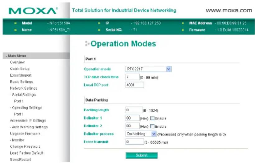
TCP alive check time
| Setting | Factory Default | Necessity |
| 0 to 99 min | 7 min | Optional |
0 min: TCP connection is not closed due to an idle TCP connection.
1 to 99 min: The NPort 5100A automatically closes the TCP connection if there is no TCP activity for the given time. After the connection is closed, the NPort 5100A starts listening for another host's TCP connection.
Local TCP port
| Setting | Factory Default | Necessity |
| 1 to 65535 | 4001 | Required |
The "Local TCP port" is the TCP port that the NPort 5100A uses to listen to connections, and that other devices must use to contact the NPort 5100A. To avoid conflicts with well known TCP ports, the default is set to 4001.
Packing length
| Setting | Factory Default | Necessity |
| 0 to 1024 0 Optional |
Default = 0: The Delimiter Process will be followed, regardless of the length of the data packet. If the data length (in bytes) matches the configured value, the data will be forced out. The data length can be configured for 0 to 1024 bytes. Set to 0 if you do not need to limit the length.
Delimiter 1
| Setting | Factory Default | Necessity |
| 00 to FF | None | Optional |
Delimiter 2
| Setting | Factory Default | Necessity |
| 00 to FF | None | Optional |
Once the NPort 5100A receives both delimiters through its serial port, it immediately packs all data currently in its buffer and sends it out the NPort 5100A's Ethernet port.
Delimiter process
| Setting | Factory Default | Necessity |
| Do Nothing, Delimiter + 1, Delimiter + 2, Strip Delimiter | Do Nothing Optional |
[Delimiter + 1] or [Delimiter + 2]: The data will be transmitted when an additional byte (for Delimiter + 1), or an additional 2 bytes (for Delimiter + 2) of data is received after receiving the Delimiter.
[Strip Delimiter]: When the Delimiter is received, the Delimiter is deleted (i.e., stripped), and the remaining data is transmitted.
[Do Nothing]: The data will be transmitted when the Delimiter is received.
Force transmit
| Setting | Factory Default | Necessity |
| 0 to 65535 ms | 0 ms | Optional |
0: Disable the force transmit timeout.
1 to 65535: Forces the NPort 5100A's TCP/IP protocol software to try to pack serial data received during the specified time into the same data frame.
This parameter defines the time interval during which the NPort 5100A fetches the serial data from its internal buffer. If data is incoming through the serial port, the NPort 5100A stores the data in the internal buffer. The NPort 5100A transmits data stored in the buffer via TCP/IP, but only if the internal buffer is full or if the Force transmit time interval reaches the time specified under Force transmit timeout.
The optimal Force transmit timeout depends on your application, but it must be at least larger than one character interval within the specified baudrate. For example, assume that the serial port is set to 1200 bps, 8 data bits, 1 stop bit, and no parity. In this case, the total number of bits needed to send a character is 10 bits, and the time required to transfer one character is
(10 (bits) / 1200 (bits/s)) * 1000 (ms/s) = 8.3 ms.
Therefore, you should set Force transmit timeout to a value larger than 8.3 ms, so in this case, it must be greater than or equal to 10 ms.
If the user wants to send a series of characters in the same packet, the serial device attached to the NPort 5100A should send that series of characters during a time interval less than the Force transmit timeout for the NPort 5100A, and the total length of data must be less than or equal to the NPort 5100A's internal buffer size. The serial communication buffer size for the NPort 5100A is 1 KB per port.
TCP Server Mode
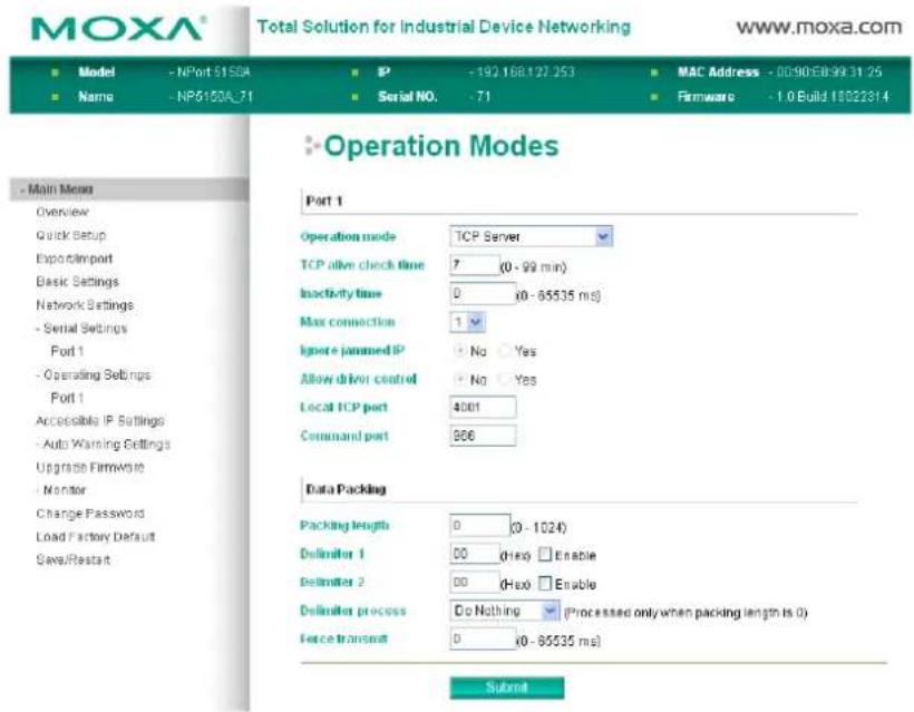
TCP alive check time
| Setting | Factory Default | Necessity |
| 0 to 99 min | 7 min | Optional |
0 min: TCP connection is not closed due to an idle TCP connection.
1 to 99 min: The NPort 5100A automatically closes the TCP connection if there is no TCP activity for the given time. After the connection is closed, the NPort 5100A starts listening for another host's TCP connection.
Inactivity time
| Setting | Factory Default | Necessity |
| 0 to 65535 ms | 0 ms | Optional |
0 ms: TCP connection is not closed due to an idle serial line.
0-65535 ms: The NPort 5100A automatically closes the TCP connection if there is no serial data activity for the given time. After the connection is closed, the NPort 5100A starts listening for another host's TCP connection.
This parameter defines the maintenance status as Closed or Listen for the TCP connection. The connection is closed if there is no incoming or outgoing data through the serial port during the specific Inactivity time.
If the Inactivity time is set to 0, the current TCP connection is kept active until a connection close request is received. Although Inactivity time is disabled, the NPort 5100A will check the connection status between the NPort 5100A and remote host by sending "keep alive" packets periodically. If the remote host does not respond to the packet, the NPort 5100A assumes that the connection was closed down unintentionally. The NPort 5100A will then force the existing TCP connection to close.

ATTENTION
The Inactivity time should at least be set larger than that of the Force transmit timeout. To prevent the unintended loss of data due to the session being disconnected, it is highly recommended that this value is set large enough so that the intended data transfer is completed.
Max connection
| Setting | Factory Default | Necessity |
| 1, 2, 3, 4, 5, 6, 7, 8 1 | Required |
Max connection is usually used when the user needs to receive data from different hosts simultaneously. The factory default only allows 1 connection at a time.
Max. connection 1: The NPort only allows 1 host to open the TCP connection to the specific serial port.
Max connection 2 to 8: Allows 2 to 8 host's TCP connection request to open this NPort 5100A's serial port, at the same time. When multiple hosts establish a TCP connection to the specific serial port at the same time, the NPort 5100A will duplicate the serial data and transmit to all of the hosts. Ethernet data is sent on a first-in-first-out basis to the serial port when data comes into the NPort 5100A from the Ethernet interface.
Ignore jammed IP
| Setting | Factory Default | Necessity |
| No or Yes No Optional |
Previously, when Max connections > 1, and the serial device is transmitting data, if any one of the connected hosts is not responding, it will wait until the data has been transmitted successfully before transmitting the second group of data to all hosts. Currently, if you select Yes for "Ignore jammed IP," the host that is not responding will be ignored, but the data will still be transmitted to the other hosts.
Allow driver control
| Setting | Factory Default | Necessity |
| No or Yes No Optional |
If "max connection" is greater than 1, the NPort will ignore driver control commands from all connected hosts. However, if you set "Allow driver control" to YES, control commands will be accepted. Note that since the NPort 5100A may get configuration changes from multiple hosts, the most recent command received will take precedence.
Packing length
| Setting | Factory Default | Necessity |
| 0 to 1024 0 Optional |
Default = 0, The Delimiter Process will be followed, regardless of the length of the data packet. If the data length (in bytes) matches the configured value, the data will be forced out. The data length can be configured for 0 to 1024 bytes. Set to 0 if you do not need to limit the length.
Delimiter 1
| Setting | Factory Default | Necessity |
| 00 to FF | None | Optional |
Delimiter 2
| Setting | Factory Default | Necessity |
| 00 to FF | None | Optional |
Once the NPort 5100A receives both delimiters through its serial port, it immediately packs all data currently in its buffer and sends it out the NPort 5100A's Ethernet port.

ATTENTION
Delimiter 2 is optional. If left blank, then Delimiter 1 alone trips clearing of the buffer. If the size of the serial data received is greater than 1 KB, the NPort 5100A will automatically pack the data and send it to the Ethernet. However, to use the delimiter function, you must at least enable Delimiter 1. If Delimiter 1 is left blank and Delimiter 2 is enabled, the delimiter function will not work properly.
Delimiter process
| Setting | Factory Default | Necessity |
| Do Nothing, Delimiter + 1, Delimiter + 2, Strip Delimiter | Do Nothing Optional |
[Delimiter + 1] or [Delimiter + 2]: The data will be transmitted when an additional byte (for Delimiter + 1), or an additional 2 bytes (for Delimiter + 2) of data are received after receiving the Delimiter.
[Strip Delimiter]: When the Delimiter is received, the Delimiter is deleted (i.e., stripped), and the remaining data is transmitted.
[Do Nothing]: The data will be transmitted when the Delimiter is received.
Force transmit
| Setting | Factory Default | Necessity |
| 0 to 65535 ms | 0 ms | Optional |
0: Disable the force transmit timeout.
1 to 65535: Forces the NPort 5100A's TCP/IP protocol software to try to pack serial data received during the specified time into the same data frame.
This parameter defines the time interval during which the NPort 5100A fetches the serial data from its internal buffer. If data is incoming through the serial port, the NPort 5100A stores the data in the internal buffer. The
NPort 5100A transmits data stored in the buffer via TCP/IP, but only if the internal buffer is full or if the Force transmit time interval reaches the time specified under Force transmit timeout.
The optimal Force transmit timeout depends on your application, but it must be at least larger than one character interval within the specified baudrate. For example, assume that the serial port is set to 1200 bps, 8 data bits, 1 stop bit, and no parity. In this case, the total number of bits needed to send a character is 10 bits, and the time required to transfer one character is
(10 (bits) / 1200 (bits/s)) * 1000 (ms/s) = 8.3 ms.
Therefore, you should set Force transmit timeout to be larger than 8.3 ms, so in this case, it must be greater than or equal to 10 ms.
If the user wants to send a series of characters in the same packet, the serial device attached to the NPort 5100A should send that series of characters during a time interval less than the Force transmit timeout for the NPort 5100A, and the total length of data must be less than or equal to the NPort 5100A's internal buffer size. The serial communication buffer size for the NPort 5100A is 1 KB per port.
Local TCP port
| Setting | Factory Default | Necessity |
| 1 to 65535 | 4001 | Required |
The "Local TCP port" is the TCP port the NPort 5100A uses to listen to connections, and that other devices must use to contact the NPort 5100A. To avoid conflicts with well known TCP ports, the default is set to 4001.
Command port
| Setting | Factory Default | Necessity |
| 1 to 65535 | 966 | Optional |
The "Command port" is a listen TCP port for IP-Serial Lib commands from the host. In order to prevent a TCP port conflict with other applications, the user can set the Command port to another port if needed. IP-Serial Lib will automatically check the Command Port on the NPort 5100A so that the user does not need to configure the program.
TCP Client Mode
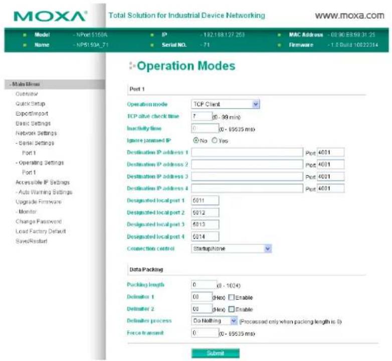
TCP alive check time
| Setting | Factory Default | Necessity |
| 0 to 99 min | 7 min | Optional |
0 min: TCP connection is not closed due to an idle TCP connection.
1 to 99 min: The NPort 5100A automatically closes the TCP connection if there is no TCP activity for the given time.
Inactivity time
| Setting | Factory Default | Necessity |
| 0 to 65535 ms | 0 ms | Optional |
0 ms: TCP connection is not closed due to an idle serial line.
0-65535 ms: The NPort 5100A automatically closes the TCP connection if there is no serial data activity for the given time.
This parameter defines the maintenance status as Closed or Listen for the TCP connection. The connection is closed if there is no incoming or outgoing data through the serial port during the specific Inactivity time.
If the Inactivity time is set to 0, the current TCP connection is kept active until a connection close request is received. Although Inactivity time is disabled, the NPort 5100A will check the connection status between the NPort 5100A and remote host by sending "keep alive" packets periodically. If the remote host does not respond to the packet, the NPort 5100A assumes that the connection was closed down unintentionally. The NPort 5100A will then force the existing TCP connection to close.

ATTENTION
The Inactivity time should at least be set larger than that of Force transmit timeout. To prevent the unintended loss of data due to the session being disconnected, it is highly recommended that this value is set large enough so that the intended data transfer is completed.

ATTENTION
Inactivity time is ONLY active when "TCP connect on" is set to "Any character."
Ignore jammed IP
| Setting | Factory Default | Necessity |
| No or Yes No Optional |
Previously, when Max connections > 1, and the serial device is transmitting data, if any one of the connected hosts is not responding, it will wait until the data has been transmitted successfully before transmitting the second group of data to all hosts. Currently, if you select Yes for "Ignore jammed IP," the host that is not responding will be ignored, but the data will still be transmitted to the other hosts.
Packing length
| Setting | Factory Default | Necessity |
| 0 to 1024 0 Optional |
Default = 0: The Delimiter Process will be followed, regardless of the length of the data packet. If the data length (in bytes) matches the configured value, the data will be forced out. The data length can be configured for 0 to 1024 bytes. Set to 0 if you do not need to limit the length.
Delimiter 1
| Setting | Factory Default | Necessity |
| 00 to FF (hex) | None | Optional |
Delimiter 2
| Setting | Factory Default | Necessity |
| 00 to FF (hex) | None | Optional |
Once the NPort 5100A receives both delimiters through its serial port, it immediately packs all data currently in its buffer and sends it to the NPort 5100A's Ethernet port.

ATTENTION
Delimiter 2 is optional. If left blank, then Delimiter 1 also ne trips clearing of the buffer. If the size of the serial data received is greater than 1 KB, the NPort 5100A will automatically pack the data and send it to the Ethernet. However, to use the delimiter function, you must at least enable Delimiter 1. If Delimiter 1 is left blank and Delimiter 2 is enabled, the delimiter function will not work properly.
Delimiter process
| Setting | Factory Default | Necessity |
| Do Nothing, Delimiter + 1, Delimiter + 2, Strip Delimiter | Do Nothing Optional |
[Delimiter + 1] or [Delimiter + 2]: The data will be transmitted when an additional byte (for Delimiter + 1), or an additional 2 bytes (for Delimiter + 2) of data is received after receiving the Delimiter.
[Strip Delimiter]: When the Delimiter is received, the Delimiter is deleted (i.e., stripped), and the remaining data is transmitted.
[Do Nothing]: The data will be transmitted when the Delimiter is received.
Force transmit
| Setting | Factory Default | Necessity |
| 0 to 65535 ms | 0 ms | Optional |
0: Disable the force transmit timeout.
1 to 65535: Forces the NPort 5100A's TCP/IP protocol software to try to pack serial data received during the specified time into the same data frame.
This parameter defines the time interval during which the NPort 5100A fetches the serial data from its internal buffer. If data is incoming through the serial port, the NPort 5100A stores the data in the internal buffer. The NPort 5100A transmits data stored in the buffer via TCP/IP, but only if the internal buffer is full or if the Force transmit time interval reaches the time specified under Force transmit timeout.
The optimal Force transmit timeout depends on your application, but it must be at least larger than one character interval within the specified baudrate. For example, assume that the serial port is set to 1200 bps, 8 data bits, 1 stop bit, and no parity. In this case, the total number of bits needed to send a character is 10 bits, and the time required to transfer one character is
(10 (bits) / 1200 (bits/s)) * 1000 (ms/s) = 8.3 ms.
Therefore, you should set Force transmit timeout to be larger than 8.3 ms, so in this case, it must be greater than or equal to 10 ms.
If the user wants to send a series of characters in the same packet, the serial device attached to the NPort 5100A should send that series of characters during a time interval less than the Force transmit timeout for the NPort 5100A, and the total length of data must be less than or equal to the NPort 5100A's internal buffer size. The serial communication buffer size for the NPort 5100A is 1 KB per port.
Destination IP address 1/2/3/4
| Setting | Factory Default | Necessity |
| IP address or Domain Name(E.g., 192.168.1.1) | None Required |
Allows the NPort 5100A to connect actively to the remote host whose IP address is set by this parameter.

ATTENTION
Up to 4 connections can be established between the NPort 5100A and hosts. The connection speed or throughput may be low if one of the four connections is slow, since the 1 slow connection will slow down the other 3 connections.

ATTENTION
The "Destination IP address" parameter can use both IP address and Domain Name. For some applications, the user may need to send the data actively to the remote destination domain name.
Designated Local Port 1/2/3/4
| Setting | Factory Default | Necessity |
| TCP Port No. 5011 (Port 1) | 5012 (Port 2) | Required |
| 5013 (Port 3) | ||
| 5014 (Port 4) |
Connection control
| Setting | Factory Default | Necessity |
| Startup/None, Any Character/None, Any Character/Inactivity Time, DSR ON/DSR OFF, DSR ON/None, DCD ON/DCD OFF, DCD ON/None | Startup/None Required |
The meaning of each of the above settings is given in the table below. In general, both the Connect condition and Disconnect condition are given.
| Connect/Disconnect Description | |
| Startup/None (default) | A TCP connection will be established on startup, and will remain active indefinitely. |
| Any Character/None | A TCP connection will be established when any character is received from the serial interface, and will remain active indefinitely. |
| Any Character/ Inactivity Time | A TCP connection will be established when any character is received from the serial interface, and will be disconnected when the Inactivity time out is reached. |
| DSR On/DSR Off | A TCP connection will be established when a DSR “On” signal is received, and will be disconnected when a DSR “Off” signal is received. |
| DSR On/None | A TCP connection will be established when a DSR “On” signal is received, and will remain active indefinitely. |
| DCD On/DCD Off | A TCP connection will be established when a DCD “On” signal is received, and will be disconnected when a DCD “Off” signal is received. |
| DCD On/None | A TCP connection will be established when a DCD “On” signal is received, and will remain active indefinitely. |
UDP Mode
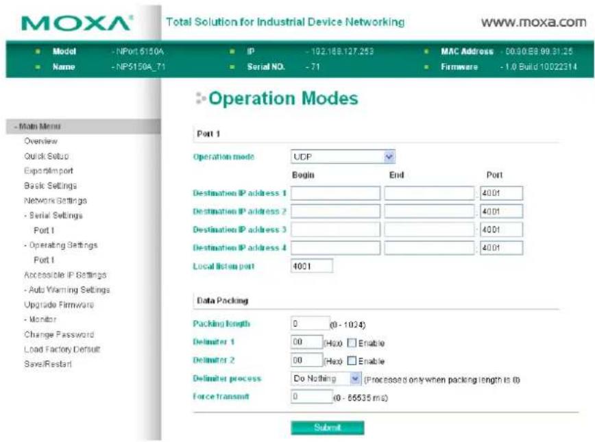
Packing length
| Setting | Factory Default | Necessity |
| 0 to 1024 0 Optional |
Default = 0: The Delimiter Process will be followed, regardless of the length of the data packet. If the data length (in bytes) matches the configured value, the data will be forced out. The data length can be configured for 0 to 1024 bytes. Set to 0 if you do not need to limit the length.
Delimiter 1
| Setting | Factory Default | Necessity |
| 00 to FF | None | Optional |
Delimiter 2
| Setting | Factory Default | Necessity |
| 00 to FF | None | Optional |
Once the NPort 5100A receives both delimiters through its serial port, it immediately packs all data currently in its buffer and sends it out the NPort 5100A's Ethernet port.

ATTENTION
Delimiter 2 is optional. If left blank, then Delimiter 1 alone trips clearing of the buffer. If the size of the serial data received is greater than 1 KB, the NPort 5100A will automatically pack the data and send it to the Ethernet. However, to use the delimiter function, you must at least enable Delimiter 1. If Delimiter 1 is left blank and Delimiter 2 is enabled, the delimiter function will not work properly.
Delimiter process
| Setting | Factory Default | Necessity |
| Do Nothing, Delimiter + 1, Delimiter + 2, Strip Delimiter | Do Nothing Optional |
[Delimiter + 1] or [Delimiter + 2]: The data will be transmitted when an additional byte (for Delimiter + 1), or an additional 2 bytes (for Delimiter + 2) of data is received after receiving the Delimiter.
[Strip Delimiter]: When the Delimiter is received, the Delimiter is deleted (i.e., stripped), and the remaining data is transmitted.
[Do nothing]: The data will be transmitted when the Delimiter is received.
Force transmit
| Setting | Factory Default | Necessity |
| 0 to 65535 ms | 0 ms | Optional |
0: Disable the force transmit timeout.
1 to 65535: Forces the NPort 5100A's TCP/IP protocol software to try to pack serial data received during the specified time into the same data frame.
This parameter defines the time interval during which the NPort 5100A fetches the serial data from its internal buffer. If data is incoming through the serial port, the NPort 5100A stores the data in the internal buffer. the NPort 5100A transmits data stored in the buffer via TCP/IP, but only if the internal buffer is full or if the Force transmit time interval reaches the time specified under Force transmit timeout.
The optimal Force transmit timeout depends on your application, but it must be at least larger than one character interval within the specified baudrate. For example, assume that the serial port is set to 1200 bps, 8 data bits, 1 stop bit, and no parity. In this case, the total number of bits needed to send a character is 10 bits, and the time required to transfer one character is
(10 (bits) / 1200 (bits/s)) * 1000 (ms/s) = 8.3 ms.
Therefore, you should set Force transmit timeout to be larger than 8.3 ms, so in this case, it must be greater than or equal to 10 ms.
If the user wants to send a series of characters in the same packet, the serial device attached to the NPort 5100A should send that series of characters during a time interval less than the Force transmit timeout for the NPort 5100A, and the total length of data must be less than or equal to the NPort 5100A's internal buffer size. The serial communication buffer size for the NPort 5100A is 1 KB per port.
Destination IP address 1
| Setting | Factory Default | Necessity | |
| IP address rangeE.g., Begin: 192.168.1.1End: 192.168.1.10 | Begin: Empty Required | ||
| End: Empty | |||
| Port: 4001 | |||
Destination IP address 2/3/4
| Setting | Factory Default | Necessity | |
| IP address range | Begin: Empty Optional | ||
| E.g., Begin: 192.168.1.11 | End: Empty | ||
| End: 192.168.1.20 | Port: 4001 | ||
Local listen port
| Setting | Factory Default | Necessity |
| 1 to 65535 | 4001 | Required |
The UDP port that the NPort 5100A listens to, and that other devices must use to contact the NPort 5100A. To avoid conflicts with well known UDP ports, the default is set to 4001.
UDP Multicast
A multicast is a packet sent by one host to multiple hosts. In multicast, each host that belongs to a specific multicast group will receive multicast packets for that group. To configure a host as a multicast receiver over the Internet, it must inform the routers on its LAN. The Internet Group Management Protocol (IGMP) is used to communicate group membership information between hosts and routers on a LAN. The NPort 5100A supports IGMP version 2.
You could type the IP address (e.g., 239.1.1.1) of the assigned multicast group into the Destination IP address column, after which the NPort will automatically add the Group and start receiving all packets from the group in accordance with the multicast function.
Pair Connection Mode
Pair Connection Master Mode
When you select Pair Connection Master Mode for the Operation mode of one of the NPort 5100A device servers this NPort 5100A will be acting as a TCP client.
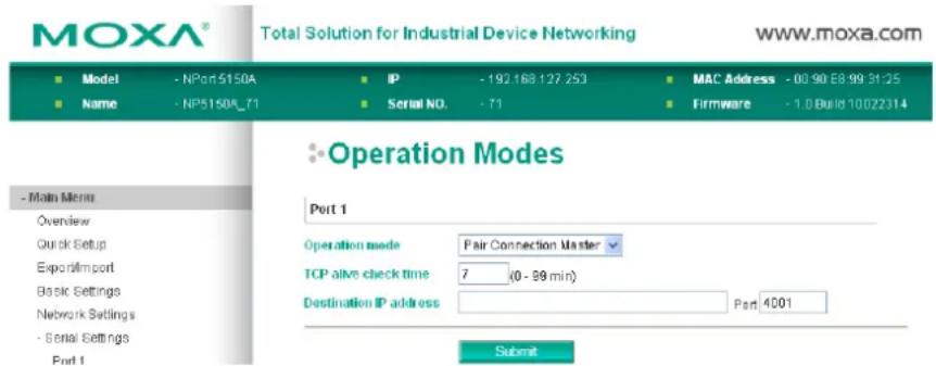
TCP alive check time
| Setting | Factory Default | Necessity |
| 0 to 99 min | 7 min | Required |
0 min: TCP connection is not closed due to an idle TCP connection.
1 to 99 min: The NPort 5100A closes the TCP connection automatically if there is no TCP activity for the given time.
Destination IP address
| Setting | Factory Default | Necessity |
| IP address or Domain Name(E.g., 192.168.1.1) | blank Optional | |
| TCP port No. 4001 Required | ||
The Pair Connection "Master" will contact the network host that has this IP address. Data will be transmitted through the port No. (4001 by default). Note that you must configure the same TCP port No. for the device server acting as the Pair Connection "Slave."
Pair Connection Slave Mode
When you select Pair Connection Slave Mode for the Operation mode of one of the NPort 5100A device servers this NPort 5100A will be acting as a TCP server.
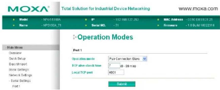
TCP alive check time
| Setting | Factory Default | Necessity |
| 0 to 99 min | 7 min | Required |
0 min: TCP connection is not closed due to an idle TCP connection.
1 to 99 min: The NPort 5100A closes the TCP connection automatically if there is no TCP activity for the given time.
Local TCP port
| Setting | Factory Default | Necessity |
| TCP port No. (e.g., 4001) | 4001 Required |
This Port No. must be the same port No. that you set up for the Pair Connection "Master" device server
Ethernet Modem Mode
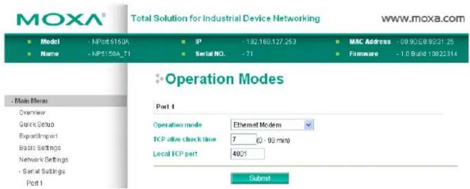
Dial-in
The NPort 5100A listens for a TCP/IP connection request from the remote Ethernet modem or host. The NPort 5100A's response depends on the ATSO value, as outlined below.
ATS0=0 (default):
The NPort 5100A will temporarily accept the TCP connection and then send the "RING" signal out through the serial port. The serial controller must reply with "ATA" within 2.5 seconds to accept the connection request, after which the NPort 5100A enters data mode. If no "ATA" command is received, the NPort 5100A will disconnect after sending three "RING" signals.
ATS0≥1:
The NPort 5100A will accept the TCP connection immediately and then send the "CONNECT
Dial-out
The NPort 5100A accepts the AT command "ATD
Disconnection Request from the Local Site
When the NPort 5100As is in data mode, the user can drive the DTR signal to OFF, or send "+++" from the local serial port to the NPort 5100A. The NPort 5100A will enter command mode and return "NO CARRIER" via the serial port, and then input "ATH" to shut down the TCP connection after 1 second.
NOTE The “+++” command cannot be divided. The “+” character can be changed in register S2, and the guard time, which prefixes and suffixes the “+++” in order to protect the raw data, can be changed in register S12.
Disconnection Request from the Remote Site
After the TCP connection has been shut down by the remote Ethernet modem or PC, the NPort 5100A will send the "NO CARRIER" signal via the serial port and then return to command mode.
AT Commands
The NPort 5100A supports the following common AT commands used with a typical modem:
| No. | AT command | Description | Remarks |
| 1 ATA | Answer manually | ||
| 2 | ATD: | Dial up the IP address: Port No. | |
| 3 ATE | ATE0=Echo OFF | ATE1=Echo ON (default) | |
| 4 ATH | ATH0=On-hook (default) | ATH1=Off-hook | |
| 5 | ATI, ATI0, ATI1, ATI2 | Modem version | reply "OK" only |
| 6 | ATL | Speaker volume option | reply "OK" only |
| 7 | ATM | Speaker control option | reply "OK" only |
| 8 ATO | On line command | ||
| 9 | ATP, ATT | Set Pulse/Tone Dialing mode | reply "OK" only |
| 10 | ATQ0, ATQ1 | Quiet command (default=ATQ0) | |
| 11 | ATSr=n | Change the contents of S register | See "S registers" |
| 12 | ATSr? | Read the contents of S register | See "S registers" |
| 13 | ATV Result code type | ATV0 for digit codeATV1 for text code0=OK1=connect (default)2=ring3=No carrier4=error | |
| 14 | ATZ | Reset (disconnect, enter command mode and restore the flash settings) | |
| 15 | AT&C | Serial port DCD control AT&C0=DCD always on AT&C1=DTE detects connection by DCD on/off (default) | |
| 16 | AT&D | Serial port DTR control AT&D0=recognize DTE always ready AT&D1, AT&D2=reply DTE when DTR On (default) | |
| 17 | AT&F | Restore manufacturer's settings | |
| 18 | AT&G | Select guard time | reply "OK" only |
| 19 | AT&R | Serial port RTS option command | reply "OK" only |
| 20 | AT&S | Serial port DSR control | reply "OK" only |
| 21 | AT&V | View settings | |
| 22 | AT&W | Write current settings to flash for next boot up | |
S Registers
| No. | S Register | Description & default value | Remarks |
| 1 S0 | Ring to auto-answer (default=0) | ||
| 2 | S1 | Ring counter (always=0) | no action applied |
| 3 | S2 | Escape code character (default=43 ASCII “+”) | |
| 4 S3 | Return character (default=13 ASCII) | ||
| 5 S4 | Line feed character (default=10 ASCII) | ||
| 6 S5 | Backspace character (default= 8 ASCII) | ||
| 7 | S6 | Wait time for dial tone (always=2, unit=sec) | no action applied |
| 8 | S7 | Wait time for carrier (default=3, unit=sec) | |
| 9 | S8 | Pause time for dial delay (always=2, unit=sec) | no action applied |
| 10 | S9 | Carrier detect response time (always=6, unit 1/10 sec) | no action applied |
| 11 | S10 | Delay for hang up after carrier (always=14, unit 1/10 sec) | no action applied |
| 12 | S11 | DTMF duration and spacing (always=100 ms) | no action applied |
| 13 | S12 | Escape code guard time (default=50, unit 1/50 sec) to control the idle time for “+++” | |
TCP alive check time
| Setting | Factory Default | Necessity |
| 0 to 99 min | 7 min | Required |
0 min: TCP connection is not closed due to an idle TCP connection.
1 to 99 min: The NPort 5100A closes the TCP connection automatically if there is no TCP activity for the given time.
Local TCP port
| Setting | Factory Default | Necessity |
| 1 to 65535 | 4001 | Required |
The TCP port that other devices must use to contact this device. To avoid conflicts with standard TCP ports, the default is set to 4001.
Reverse Telnet Mode
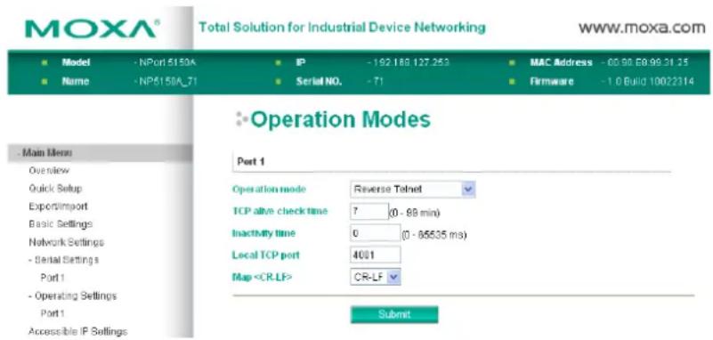
TCP alive check time
| Setting | Factory Default | Necessity |
| 0 to 99 min | 7 min | Optional |
0 min: TCP connection is not closed due to an idle TCP connection.
1 to 99 min: The NPort 5100A automatically closes the TCP connection if there is no TCP activity for the given time.
Inactivity time
| Setting | Factory Default | Necessity |
| 0 to 65535 ms 0 Optional |
Idle time setting for auto-disconnection. 0 min. means it will never disconnect.
Local TCP port
| Setting | Factory Default | Necessity |
| 1 to 65535 | 4001 | Required |
Each of the NPort 5100A's serial ports is mapped to a TCP port. To avoid conflicts with common TCP port numbers, set port numbers to 4001 for port 1, 4002 for port 2, etc.
Map
| Setting | Factory Default | Necessity |
| CR, LF, or CR-LF | CR-LF | Required |
If data received through the NPort 5100A's Ethernet port is sent using the "enter" command, the data will be transmitted out the serial port with additional characters, as described below:
- "carriage return + line feed" if you select the
option
(i.e., the cursor will jump to the next line, and return to the first character of the line) -
"carriage return" if you select the
option
(i.e., the cursor will return to the first character of the line) -
"line feed" if you select the
option.
(i.e., the cursor will jump to the next line, but not move horizontally)
Disabled Mode
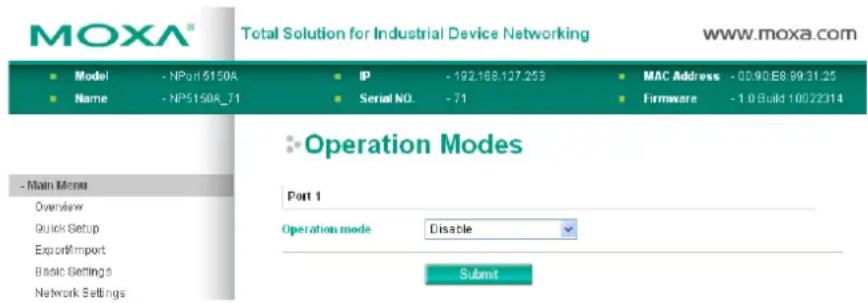
When Operation mode is set to Disabled, that particular port will be disabled. Check the "Apply the above settings to all serial ports" to apply this setting to the other port.
Accessible IP Settings
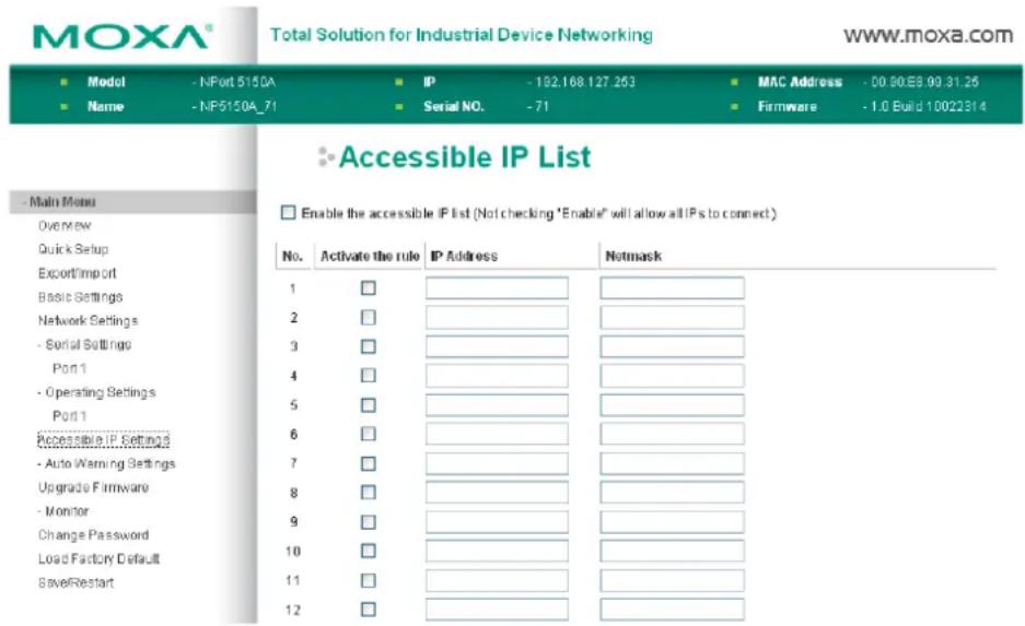
The NPort 5100A uses an IP address based filtering method to control access to itself.
Accessible IP Settings allows you to add or block remote host IP addresses to prevent unauthorized access. Access to the NPort 5100A is controlled by IP address. That is, if a host's IP address is in the accessible IP table, then the host will be allowed to access the NPort 5100A. You can allow one of the following cases by setting the parameter.
- Only one host with a specific IP address can access the NPort 5100A
Enter "IP address/255.255.255.255" (e.g., "192.168.1.1/255.255.255.255").
- Hosts on a specific subnet can access the NPort 5100A
Enter "IP address/255.255.255.0" (e.g., "192.168.1.0/255.255.255.0").
- Any host can access the NPort 5100A
Disable this function by un-checking the "Enable the accessible IP list" checkbox. Refer to the following table for more configuration examples.
| Allowable Hosts Input format | |
| Any host Disable | |
| 192.168.1.120 | 192.168.1.120 / 255.255.255.255 |
| 192.168.1.1 to 192.168.1.254 | 192.168.1.0 / 255.255.255.0 |
| 192.168.0.1 to 192.168.255.254 | 192.168.0.0 / 255.255.0.0 |
| 192.168.1.1 to 192.168.1.126 | 192.168.1.0 / 255.255.255.128 |
| 192.168.1.129 to 192.168.1.254 | 192.168.1.128 / 255.255.255.128 |
Auto Warning Settings
Auto warning: Email and SNMP trap
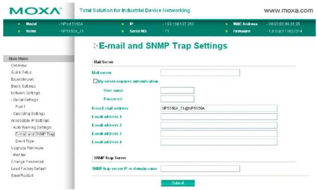
Mail Server
Mail server
| Setting | Factory Default | Necessity |
| IP Address or Domain Name | None Optional |
User name
| Setting | Factory Default | Necessity |
| 1 to 15 characters | None | Optional |
Password
| Setting | Factory Default | Necessity |
| 1 to 15 characters | None | Optional |
From E-mail address
| Setting | Factory Default | Necessity |
| 1 to 63 characters | None | Optional |
E-mail address 1/2/3/4
| Setting | Factory Default | Necessity |
| 1 to 63 characters | None | Optional |

ATTENTION
Consult your Network Administrator or ISP for the proper mail server settings. The Auto warning function may not work properly if it is not configured correctly. The NPort 5100A SMTP AUTH supports LOGIN, PLAIN, CRAM-MD5 (RFC 2554).
SNMP Trap Server
SNMP trap server IP or domain name
| Setting | Factory Default | Necessity |
| IP address or Domain Name | None Optional |
Event Type
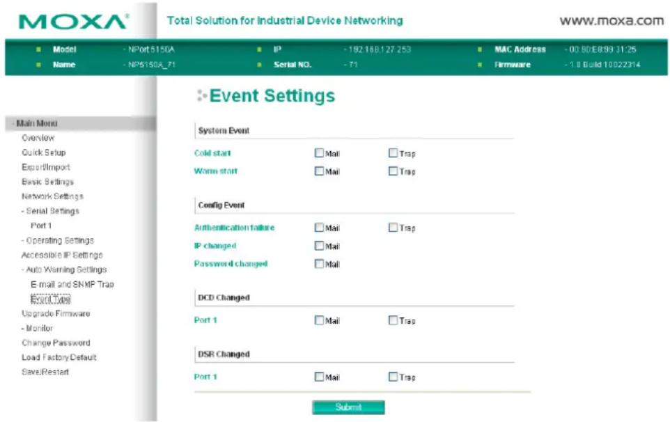
Cold start
"Cold start" refers to starting the system from power off (contrast this with warm start). When performing a cold start, the NPort 5100A will automatically issue an Auto warning message by e-mail, or send an SNMP trap after booting up.
Warm start
"Warm start" refers to restarting the computer without turning the power off. When performing a warm start, the NPort 5100A will automatically send an e-mail, or send an SNMP trap after rebooting.
Authentication failure
The user inputs a wrong password from the Console or Administrator. When authentication failure occurs, the NPort will immediately send an e-mail or send an SNMP trap.
IP address changed
The user has changed the NPort 5100A's IP address. When the IP address changes, the NPort 5100A will send an e-mail with the new IP address before the NPort 5100A reboots. If the NPort 5100A is unable to send an e-mail message to the mail server within 15 seconds, the NPort 5100A will reboot anyway, and abort the e-mail auto warning.
Password changed
The user has changed the NPort 5100A's password. When the password changes, the NPort 5100A will send an e-mail with the password changed notice before the NPort 5100A reboots. If the NPort 5100A is unable to send an e-mail message to the mail server within 15 seconds, the NPort 5100A will reboot anyway, and abort the e-mail auto warning.
DCD changed
The DCD (Data Carrier Detect) signal has changed, also indicating that the modem connection status has changed. For example, a DCD change to high also means "Connected" between local modem and remote modem. If the DCD signal changes to low, it also means that the connection line is down.
When the DCD changes, the NPort 5110A/5150A/P5150A will immediately send an e-mail or send an SNMP trap.
DSR changed
The DSR (Data Set Ready) signal has changed, also indicating that the data communication equipment's power is off. For example, a DSR change to high also means that the DCE is powered ON. If the DSR signal changes to low, it also means that the DCE is powered off.
When the DSR changes, the NPort 5110A/5150A/P5150A will immediately send an e-mail or send an SNMP trap.
| Setting | Factory Default | Necessity |
| Enable, Disable | Disable | Optional |
This feature helps the administrator manage how the NPort 5100A sends e-mail to pre-defined e-mail boxes when the enabled events—such as Cold start, Warm start, Authentication failure, etc.—occur. To configure this feature, click the Event Type Mail checkbox.
Trap
| Setting | Factory Default | Necessity |
| Enable, Disable | Disable | Optional |
This feature helps the administrator manage how the NPort 5100A sends SNMP Trap to a pre-defined SNMP Trap server when the enabled events—such as Cold start, Warm start, Authentication failure, etc.—occur. To configure this feature, click the Event Type Trap checkbox.
Upgrade Firmware
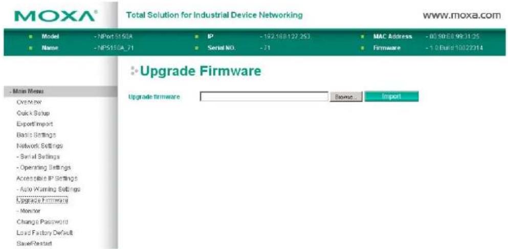
Keep your NPort 5100A up to date with the latest firmware from Moxa. Occasionally, compare your NPort firmware to the version currently available at the Moxa website (www.moxa.com). If a new firmware version is available, you can download it and click Import to upgrade your firmware.
Monitor
Monitor Line
Click Line under Monitor to show the operation mode and status of each TCP/IP connection (IPx) for the serial port.
![MOXA® Total Solution for Industrial Device Networking www.moxa.com ■ Model - NPort 5150A ■ IP - 192 168.127.253 ■ MAC Address - 00:30:E8.99:31:25 ■ Name - NP5150A_71 ■ Serial NO. - 71 ■ Firmware - 1.0 Built 10022314 Monitor Line Main Menu Overview Quick Setup Export/Import Basic Settings Network Settings - Serial Settings - Operating Settings Accessible IP Settings - Auto Warning Settings Upgrade Firmware - Monitor Line Async Acrop Settings Change Password Load Factory Default SaveReport Port Operation Mode Connections 1 RealCOM [192.168.32.41] [ ] [ ] [ ] [ ] [ ] [ ]](/content/2026/06/1274135/images/545932f9ea4b5ad916023a5d3d98bf34948c91033e26e7930ca63a522b04f045.jpg)
Monitor Async
Click Async under Monitor to show the current status of the serial port.
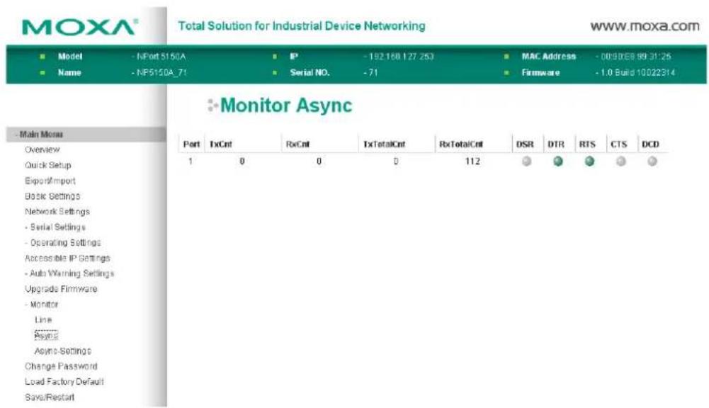
Monitor Async-Settings
Click Async Setting under Monitor to show the run-time settings for the serial port.
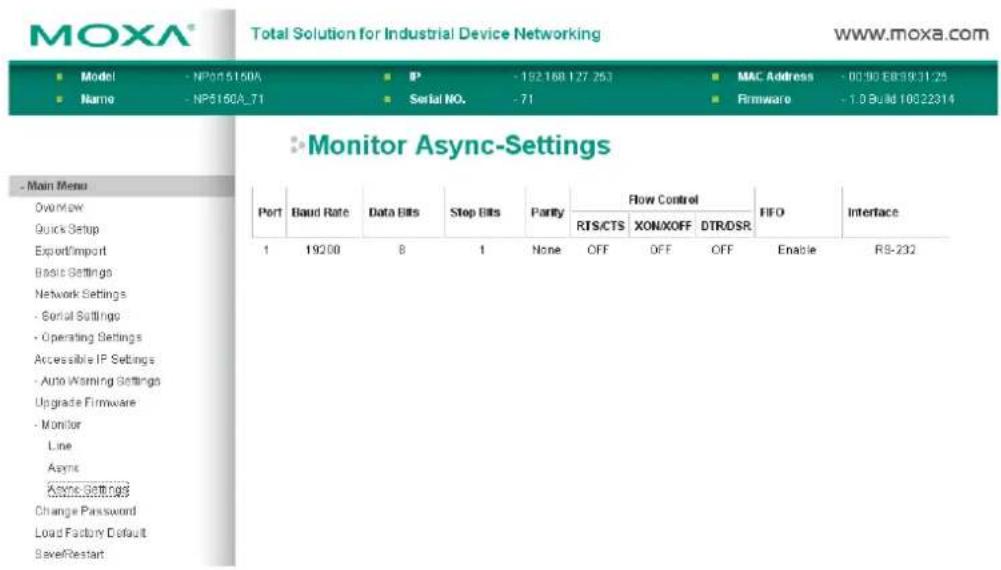
Change Password
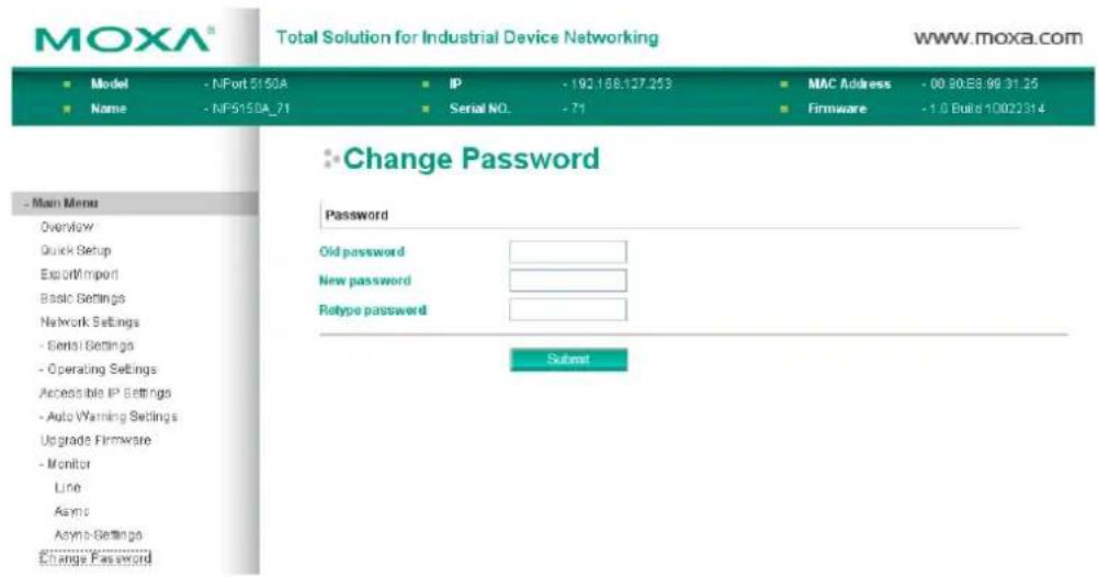
Input the "Old password" and "New password" to change the password. Leave the password boxes blank to erase the password. If the password is erased, then NPort 5100A will not have password protection.

ATTENTION
If you forget the password, the ONLY way to configure the NPort 5100A is by using the Reset button on the NPort 5100A's casing to "Load Factory Default."
Remember to export the configuration file when you finish the configuration. By using the Import function your configuration can be re-loaded into the NPort 5100A after using "Load Factory Default."
Load Factory Default
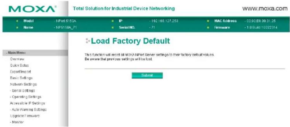
This function will reset all of the NPort 5100A's settings to the factory default values. Be aware that previous settings will be lost.
The following topics are covered in this chapter:
Overview
□ Installing NPort Administrator
□ Configuration
▶ Broadcast Search
Unlock Password Protection
➢ Configuring the NPort 5100A
- Upgrading the Firmware
Export Configuration
Import Configuration
Monitor
Initiating the Monitor Function
➢ Using the Monitor Function
Port Monitor
□ COM Mapping
Creating a COM Group
➢ Deleting a COM Group
➢ Adding a Port to a COM Group
Removing a Port from a COM Group
Modify Ports in a COM Group
□ IP Address Report
Overview
Device Server Administrator lets you install and configure your NPort 5100A Series products easily over the network. Five function groups are provided to ease the installation process, allow off-line COM mapping, and provide monitoring and IP location server functions.
Device Server Administrator is an integrated software suite that bundles Device Server Administrator and the IP Serial Library, and provides everything you need to manage, monitor, and modify your NPort 5100A from a remote location.
Installing NPort Administrator
- Once the Setup program starts running, click Next when the Welcome window opens to proceed with the installation.
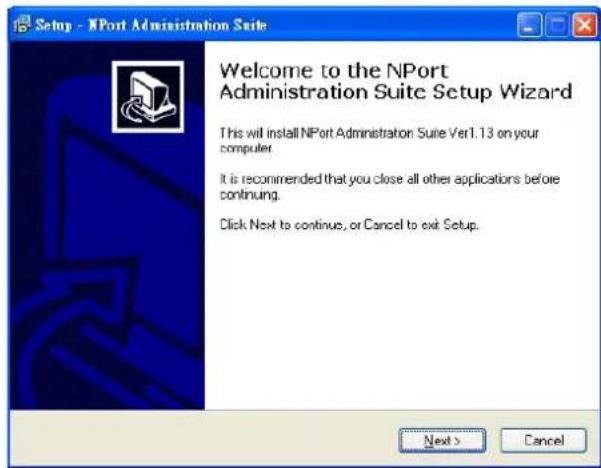
- Click Next to install program files in the default directory, or select an alternative location.
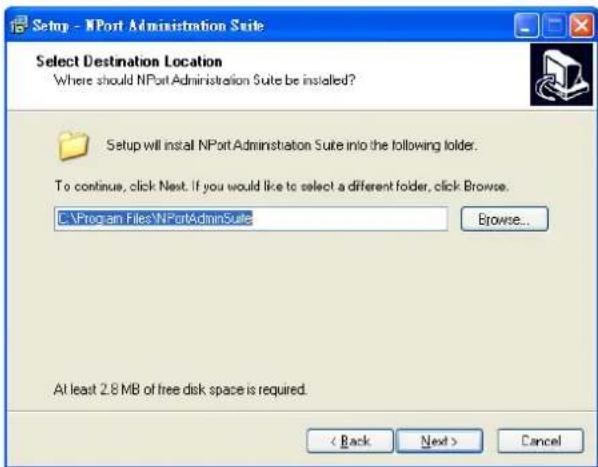
- Click Next to install the program using the default program name, or select a different name.
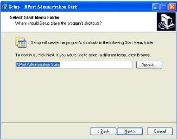
- Click Install to proceed with the installation.
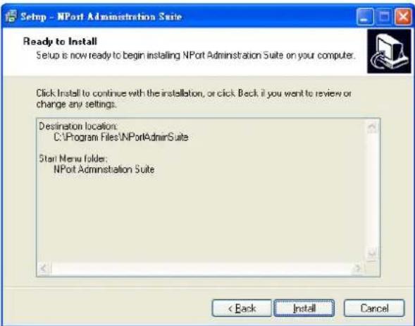
- The Installing window reports the progress of the installation.
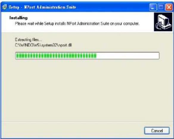
- Click Next to proceed with the installation.
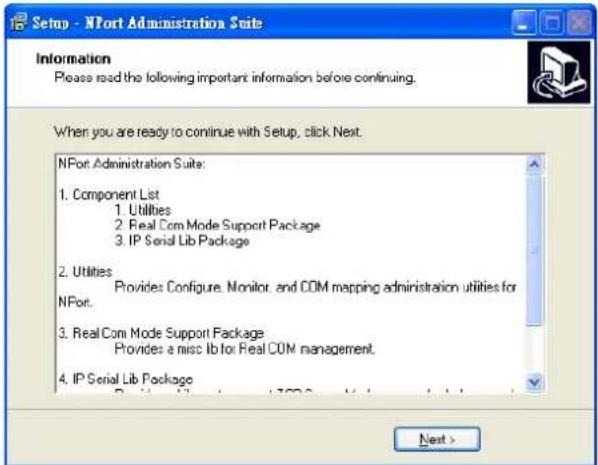
- Click Finish to complete the installation of NPort Administration Suite.
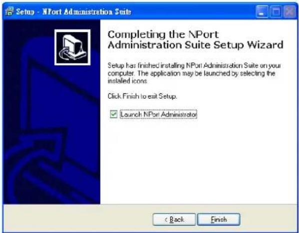
Configuration
The Administrator-Configuration window is divided into four parts.
- The top section contains the function list and online help area. (Windows NT does not support this .chm file format.)
• The five Administrator function groups are listed in the left section. - A list of the NPort 5100A serial device servers, each of which can be selected to process user requirements, is displayed in the right section.
- The activity Log, which displays messages that record the user's processing history, is shown in the bottom section.
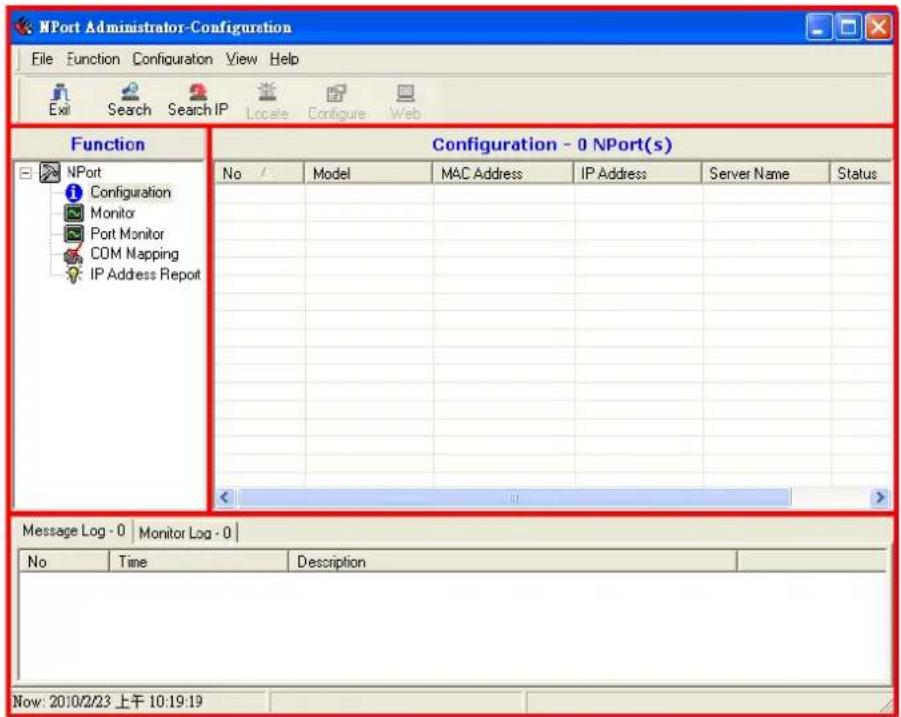
Broadcast Search
The Broadcast Search function is used to locate all NPort 5100As that are connected to the same LAN as your computer. Since the Broadcast Search function searches by MAC address and not IP address, all NPort 5100As connected to the LAN will be located, regardless of whether or not they are part of the same subnet as the host.
- Position the cursor in the right middle section of the Administrator window and then click the right mouse button.
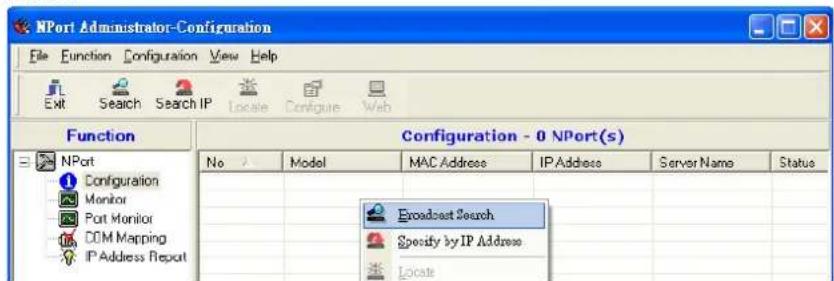
- The Broadcast Search window will open and display the Model, IP Address, MAC Address, and Progress of the search for that particular device.
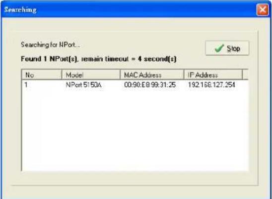
- When the search is complete, the Broadcast Search window will close, and the NPort 5100As that were located will be displayed in the right pane of the Administrator window. If you found more than one server connected to this network, refer to the MAC address sticker on your server(s) to determine which server(s) are the ones you wish to configure. To configure an NPort 5100A, place the cursor over the row displaying that NPort 5100A's information, and then double click the left mouse button.
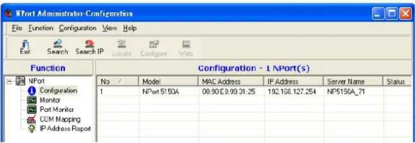

ATTENTION
Before modifying the NPort 5100A's configuration, use Broadcast Search to locate all NPort 5100As connected to the LAN, or use Specify by IP Address to locate a particular NPort 5100A.
Unlock Password Protection
If the NPort 5100A is password protected (indicated by "Lock" for Status), you will receive the following error, and you will not be able to use the right click method to open the configuration page.
![Error Target is password protected. Please [Unlock] first OK](/content/2026/06/1274135/images/28630bd03d146050b1ab560cc9de80d105d6e7cab13f69cc23a8304055c1831f.jpg)
In this case, proceed as follows to "Unlock" the device server.
- Select the NPort 5100A with "Lock" status, click the right mouse button, and then select Unlock.
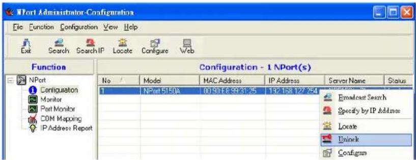
- After inputting the correct password, the Administrator will display an "Unlock ok" message.
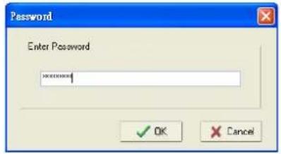

- The "Lock" status will change to "Unlock," and the Administrator utility will keep this NPort 5100A in the Unlock status throughout this Administrator session.
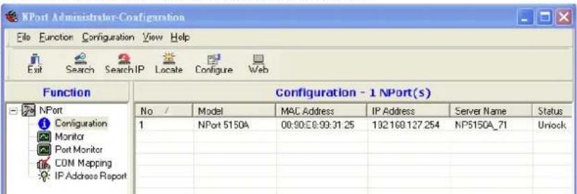
The meanings of the six "Status" states are given below (note that the term Fixed is borrowed from the standard fixed IP address networking terminology):
Lock
The NPort 5100A is password protected, "Broadcast Search" was used to locate it, and the password has not yet been entered from within the current Administrator session.
Unlock
The NPort 5100A is password protected, "Broadcast Search" was used to locate it, and the password has been entered from within the current Administrator session. Henceforth during this Administrator session, activating various utilities for this NPort 5100A will not require re-entering the server password.
Blank
The NPort 5100A is not password protected, and "Broadcast Search" was used to locate it.
Fixed
The NPort 5100A is not password protected, and "Search by IP address" was used to locate it.
Lock Fixed
The NPort 5100A is password protected, "Specify by IP address" was used to locate it, and the password has not yet been entered from within the current Administrator session.
Unlock Fixed
The NPort 5100A is password protected, "Specify by IP address" was used to locate it, and the password has been entered from within the current Administrator session. Henceforth during this Administrator session, activating various utilities for this NPort 5100A will not require re-entering the server password.
Configuring the NPort 5100A
In this section, we illustrate how to access the NPort 5100A's configuration utility. You should first make sure that you can connect over the network from your computer to the NPort 5100A.
- To start NPort Administrator, click Start → Programs → NPort Administration Suite → NPort Administrator.
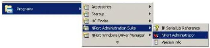
- Unlock the NPort 5100A you wish to configure if it is password protected. Right click the NPort 5100A and select Configure to start the configuration process.
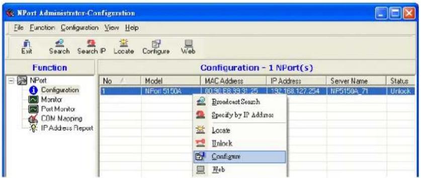
- The progress bar shows that Administrator is retrieving configuration information from the specific NPort 5100A.
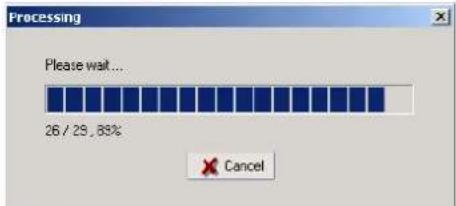
- Refer to Chapter 5 for each parameter's function definition. To modify the configuration, you must first click in the modify box to activate the parameter setting box.
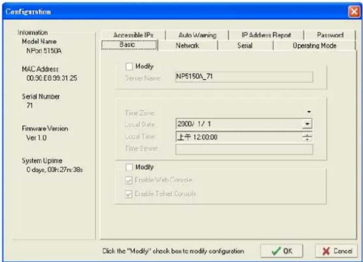

ATTENTION
You can simultaneously modify the configurations of multiple NPort 5100As that are of the same model. To select multiple NPort 5100As, hold down the Ctrl key when selecting additional NPort 5100As, or hold down the Shift key to select a group of NPort 5100As.
Upgrading the Firmware
Follow these steps to upgrade the firmware of an NPort 5100A.
- To start NPort Administrator, click Start → NPort Administration Suite → NPort Administrator.
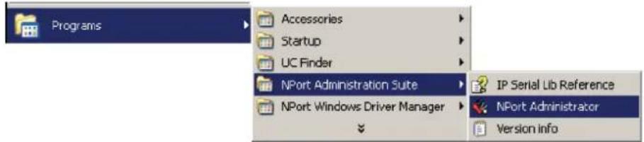
- Unlock the NPort 5100A you wish to configure if it is password protected. Right click a specific NPort 5100A and select the Upgrade Firmware function to start upgrading the firmware.
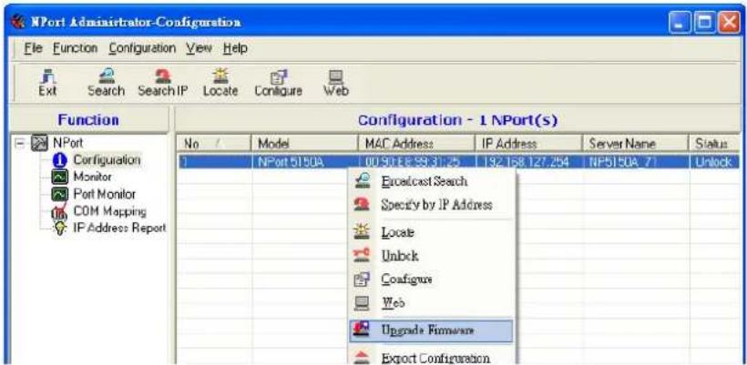
- Select the correct ROM file to download.
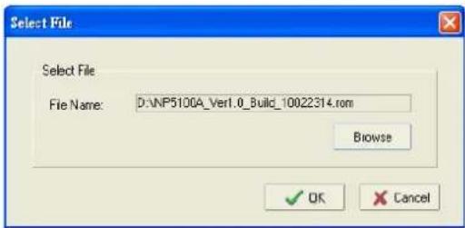
- Wait while the Upgrade Firmware action is processed.
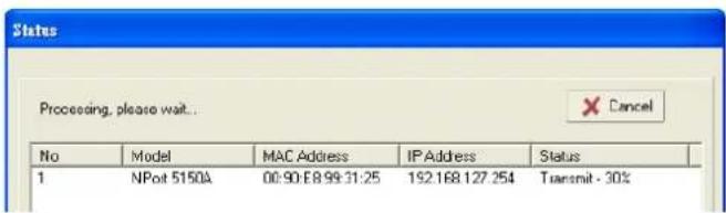

ATTENTION
You can simultaneously upgrade the firmware of multiple NPort 5100As that are of the same model. To select multiple NPort 5100As, hold down the Ctrl key when selecting an additional NPort 5100A, or hold down the Shift key to select a block of NPort 5100As.
Export Configuration
To export the configuration of an NPort 5100A, right click the NPort 5100A, select Export Configuration, and then follow the onscreen instructions. The Export Configuration function is a handy tool that can be used to produce a text file containing the current configuration of a particular NPort 5100A.
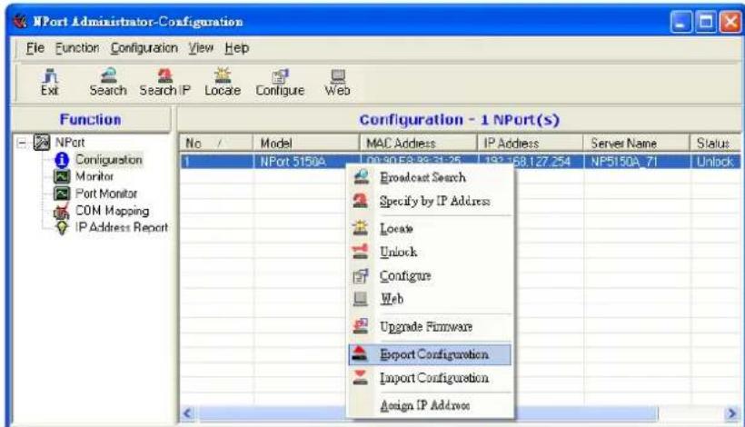
Import Configuration
The Import Configuration function is used to import an NPort 5100A configuration from a file into one or more NPort 5100As of the same model. To import a configuration, first select the target servers, click the right mouse button, and then select Import Configuration. Follow the onscreen instructions to locate the configuration file and start downloading the file.
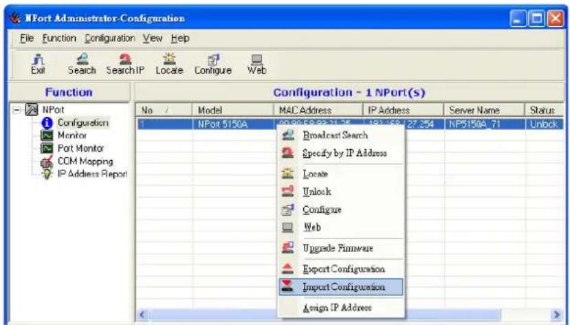
Monitor
Initiating the Monitor Function
To initiate the Monitor function, click Broadcast Search → Monitor → Add Target.
- With Configuration selected under Function, use Broadcast Search to locate all NPorts on your LAN.
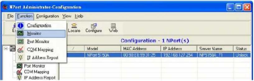
- Next, click Monitor → Add Target and select your targets from the list, and then click OK.
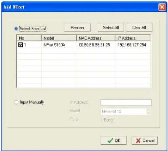
Using the Monitor Function
- The NPort 5100A list will appear on the Monitor screen.
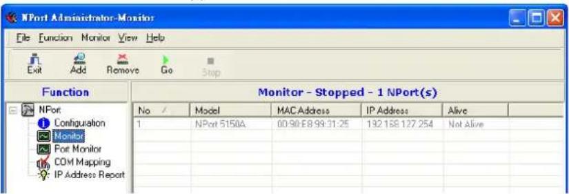
- Right click the panel and select Settings.
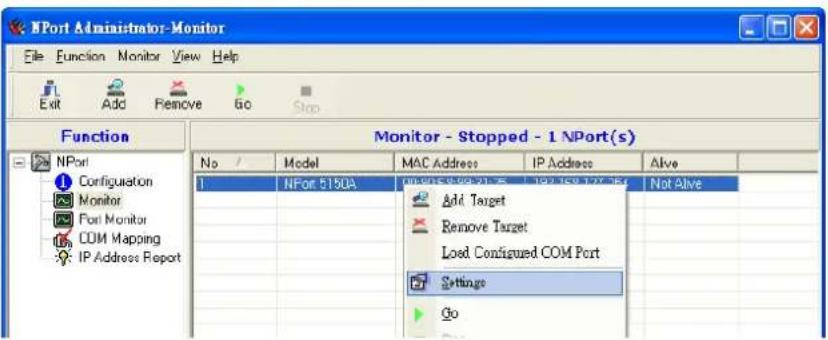
- Select or de-select Monitor Items. Use the single arrowhead buttons to move highlighted items from one box to the other. Use the double arrowhead buttons to move all items in one box to the other.
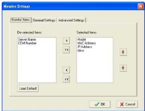
- Select a Refresh Rate (the default is 3 seconds) on the General Settings page.
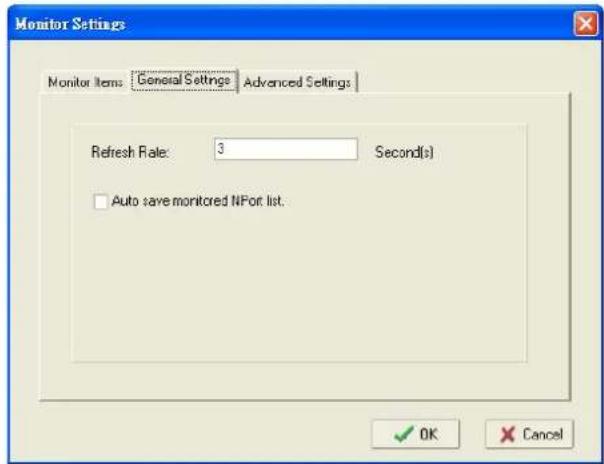
- On the Advanced Settings page, select Display warning message for new event and/or Play warning music for new event. In the second case, you must enter the path to the WAV file that you want to be played. "New event" means that one of the NPort 5100As in the monitor is "Alive" or "Not Alive," or has lost connection with the Monitor program.
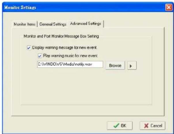
- Right click in the NPort 5100A list section and select Go to start Monitoring the NPort 5100A.
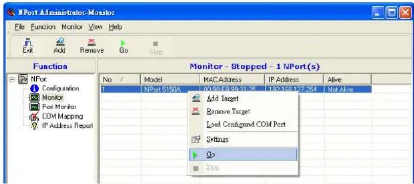
- For this example, the NPort 5100As shown in the list will be monitored.
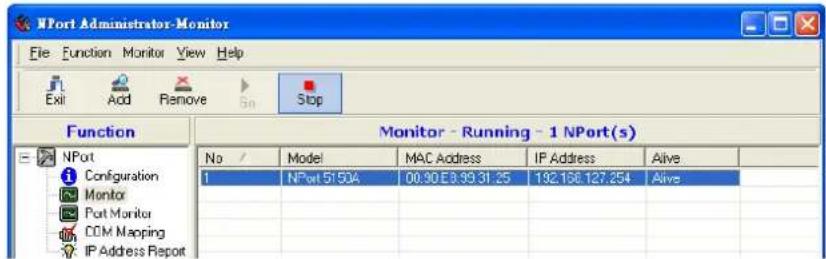
- When one of the NPort 5100As loses connection with the Monitor program, a warning alert will display automatically. The warning music will be played at the same time.
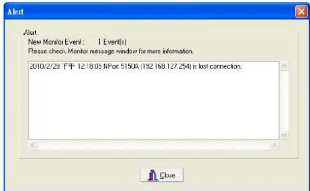
- In the Monitor screen, you can see that the NPort 5100As that are "Not Alive" are shown in red color.
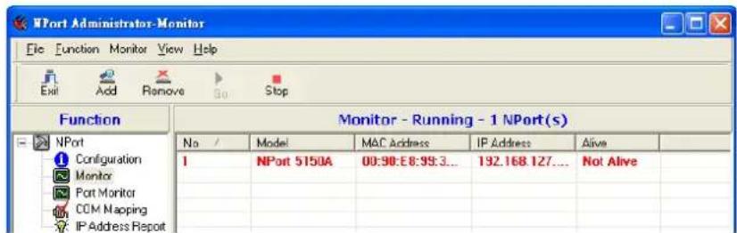
- If the NPort 5100A gets reconnected, a warning will be displayed to remind the user that the NPort 5100A is now "Alive."
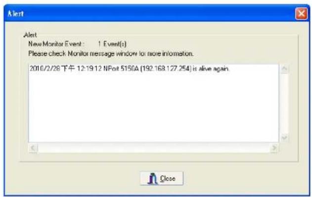
- The NPort 5100As that were reconnected, and are now "Alive," will be shown in black color.
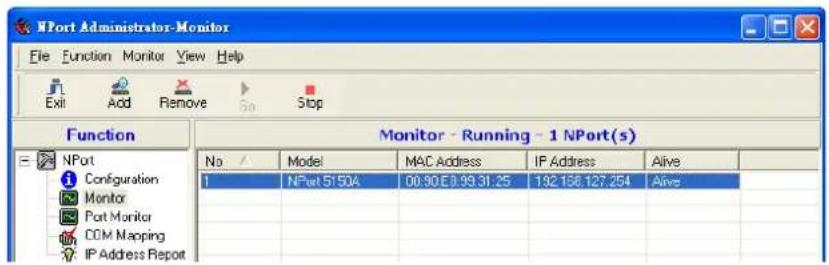
Port Monitor
The process described here is the same as in the previous "Monitor" section. The only difference is that you can select more items under Port Monitor than under Monitor.
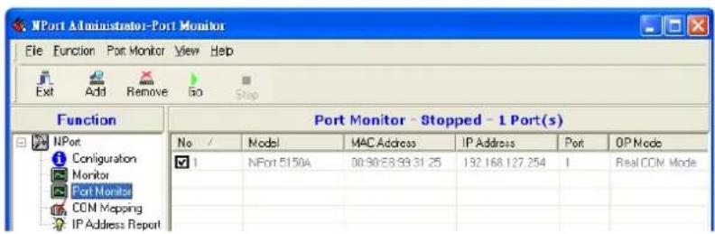
Select or de-select Monitor Items. Use the single arrowhead buttons to move highlighted items from one box to the other. Use the double arrowhead buttons to move all items in one box to the other.
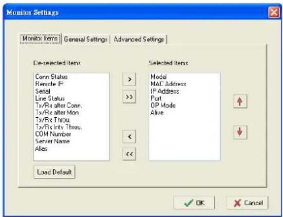
COM Mapping
Windows Administration Suite comes with Windows Real COM drivers. After you install NPort Administration Suite, there are two ways to set up the NPort 5100A serial port as your host's remote COM port.
The first way is with On-line COM Mapping. On-line COM Mapping will check to make sure that the NPort 5100A is connected correctly to the network and then install the driver on the host computer.
The second way is with Off-line COM Installation, without first connecting the NPort 5100A to the network. Off-line COM Mapping can decrease the system integrator's effort by solving different field problems. Via off-line installation, users can first process software installation for the host, and then install the NPort 5100A to different fields.
Use the following procedure to map COM ports:
Connect the NPort 5100A to the network → Set NPort 5100A to the proper IP address → Map COMs to your host → Apply Change.
Map COMs to your host → Apply Change → Connect the NPort 5100A to the network → Configure NPort 5100A's IP address.
On-line COM Mapping
- Broadcast Search for NPort 5100As on the network.
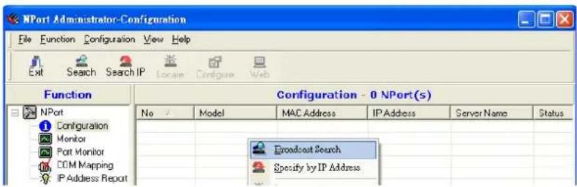
- Select the COM Mapping function group.
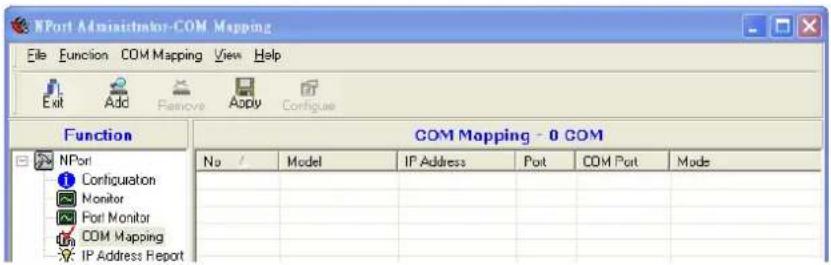
- Add the target to which you would like to map COM ports.
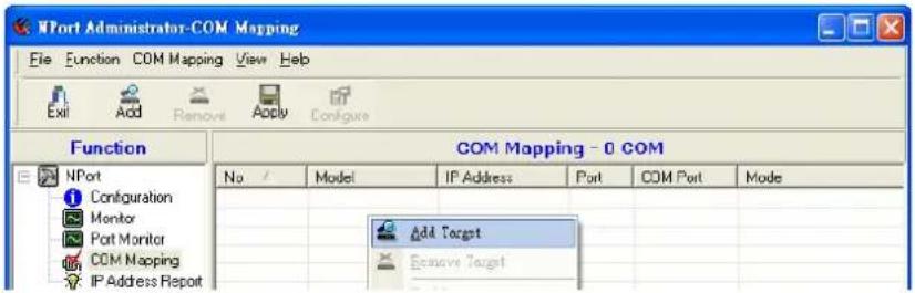
- The NPort 5100A list that appears is the list generated by the previous Broadcast Search. Select the NPort 5100A to which you would like to map COM ports.
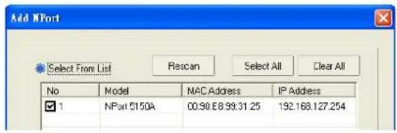
- Select COM Settings to modify COM No., default setting, etc.
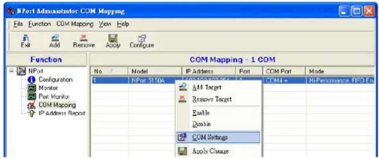
- Select the COM Number.
COM ports that are "In use" or "Assigned" will also be indicated in this drop-down list. If you select multiple serial ports or multiple NPort 5100As, remember to check the "Auto Enumerating" function to use the COM No. you select as the first COM No.
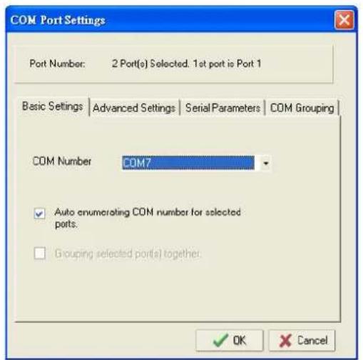
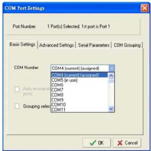
- Hi-performance mode is the default for Tx mode. If the driver completes sending data out to the NPort 5100A, the driver will respond "Tx Empty" to the program.
Under classical mode, the driver will not notify the user's program that Tx is completed until all Tx data has been sent out from the NPort 5100A; this mode will cause lower throughput. If you want to ensure that all data is sent out before further processing, classical mode is recommended.
Enable/Disable Tx/Rx FIFO. If disabled, the NPort 5100A will send one byte each time the Tx FIFO becomes empty; and an Rx interrupt will be generated for each incoming byte. This will result in a faster response and lower throughput. If you want to use XON/XOFF flow control, we recommend setting FIFO to Disable.
Fast Flush (only flush local buffer)
- We have added one optional Fast Flush function to Moxa's new NPort Real COM driver. Starting from version 1.2, NPort Administrator Suite for NPort supports Fast Flush.
- For some applications, the user's program will use the Win32 "PurgeComm()" function before it reads or writes data. With our design, after the program uses this Purge Comm() function, the NPort driver will keep querying the NPort's firmware several times to make sure there is really no data queued in the NPort firmware buffer, rather than just flushing the local buffer. This kind of design is used because of some special considerations. However, it might take more time (on the order of several hundred
milliseconds) than a native COM1, because it needs to work via Ethernet. That's why the native COM ports on the motherboard can work fast with this function call, but the NPort requires much more time. In order to accommodate other applications that require a faster response time, the new NPort driver implements a new "Fast Flush" option. Note that by default, this function is disabled.
- To begin with, make sure there are some "PurgeComm()" functions being used in your application program. In this kind of situation, you might find that your NPort exhibits a much poorer operation performance than when using the native COM1 port. Once you have enabled the "Fast Flush" function, you can check to see if there has been an improvement in performance.
- By default, the optional "Fast Flush" function is disabled. If you would like to enable this function, from "NPort Administrator" double click the COM ports that are mapped to the NPort, and then select the "Fast Flush" checkbox. You should find that when "Fast Flush" is enabled, the NPort driver will work faster with "PurgeComm().
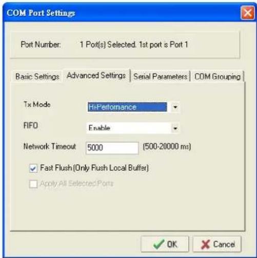
- The Serial Parameter settings shown here are the default settings when the NPort 5100A is powered on. However, the program can redefine the serial parameters to different values after the program opens the port via the Win 32 API.
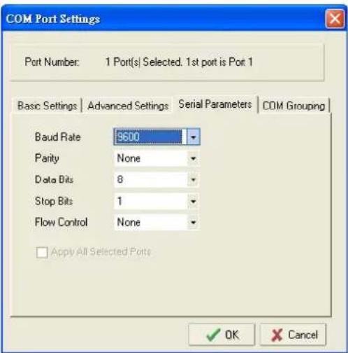
- After setting the COM Mapping, remember to select Apply Change to save the information in the host system registry. The host computer will not have the ability to use the COM port until after Apply Change is selected.
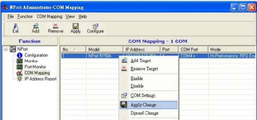
- Select Discard Change to tell Administrator NOT to save the COM Mapping information to the host.
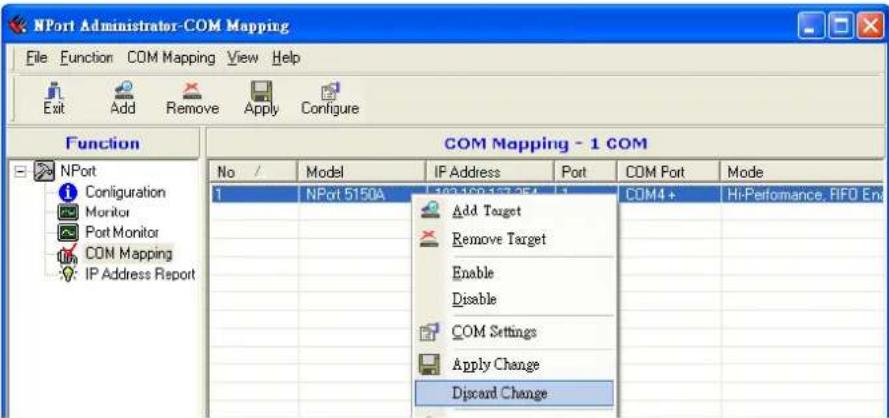
- To save the configuration to a text file, select Export COM Mapping. You will then be able to import this configuration file to another host and use the same COM Mapping settings in the other host.
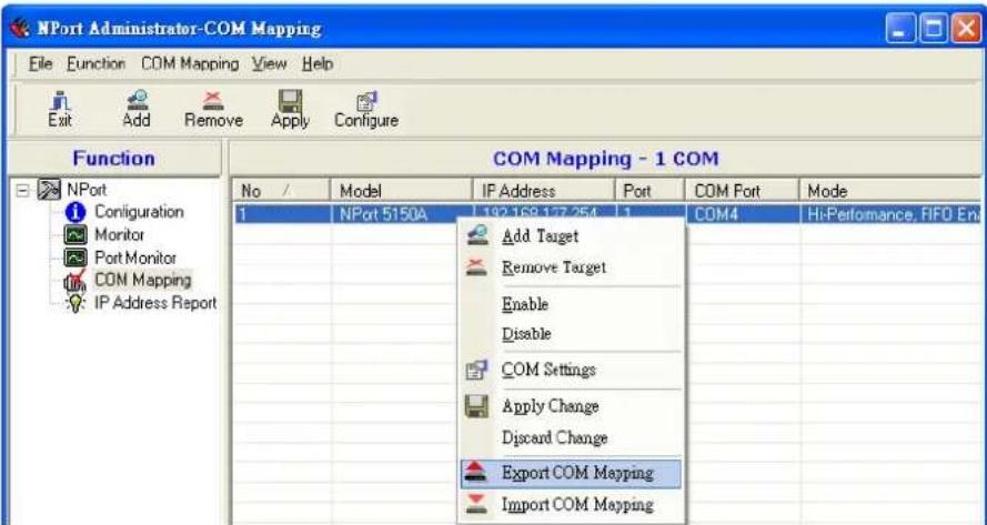
- Add a target by inputting the IP address and selecting the Model Name without physically connecting the NPort 5100A to the network.
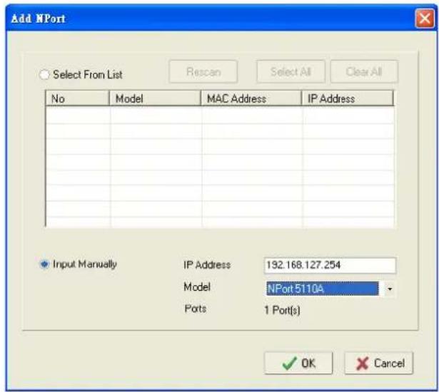
- Modify the port settings as needed.
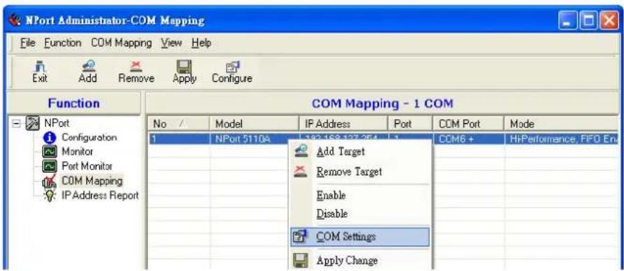
- Right click in the NPort list section and select Apply Change.
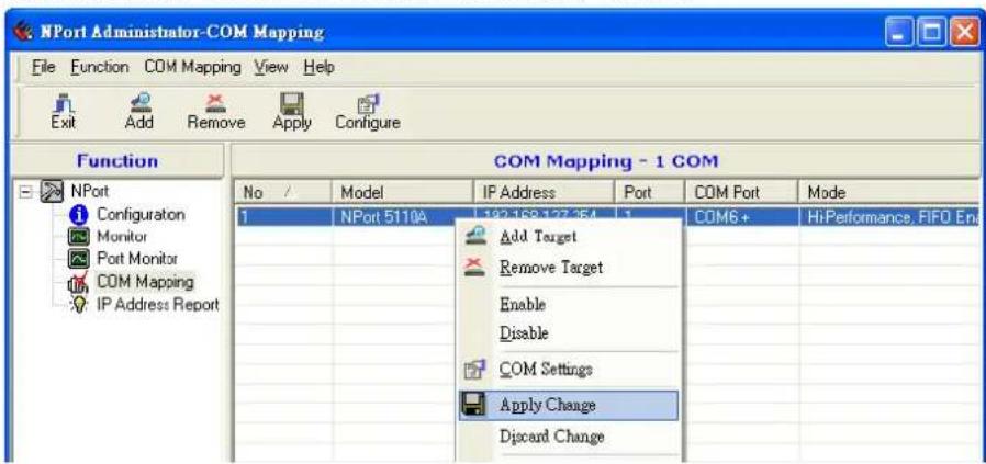
COM Grouping
The "COM Grouping" function is designed to simulate the multi-drop behavior of serial communication over an Ethernet network. COM Grouping allows you to create a COM Group and redirect data from it to several physical COM ports on NPort device servers. With COM Grouping, you will be able to control multiple physical serial ports simultaneously by operating only one COM port.
Creating a COM Group
Follow the steps below to add multiple COM ports into one group:
- Select serial port(s) for the group that you are going to create, and right-click to select COM Settings.
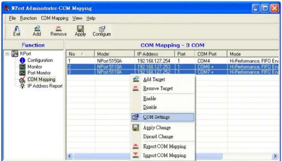
- Select a COM number for this COM group. You may select one of the ports already assigned to a member of the COM Group. However, once the COM Group is configured, all of the original COM number(s) within the group will be released simultaneously.
![COM Port Settings Port Number: 2Port(s) Selected. 1st port is Port 2 Basic Settings | Advanced Settings | Serial Parameters | COM Grouping COM Number COM6 (current) [assigned] COM6 (current) [assigned] COM7 (assigned) COM8 COM9 COM10 COM11 COM12 COM13 Auto enumerat ports. Grouping selec OK Cancel](/content/2026/06/1274135/images/abdf67bd469dac403b3ea41f55f777e4ebda29ffd624c79ffd27bef0a6e023d7.jpg)

ATTENTION
The COM Grouping function only supports Windows NT, 2000, and later. The maximum number of ports for each group is 32.
- Select the Grouping selected port(s) together checkbox.
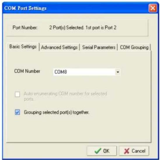
- On the COM Grouping page, you can set "Read" and "Write" permissions for every serial port. It is necessary to set Signal Status in order to control the data transmission with specified control signals (e.g., DTR/RTS). You can assign one serial port whose signals will be taken into account by the COM Group.
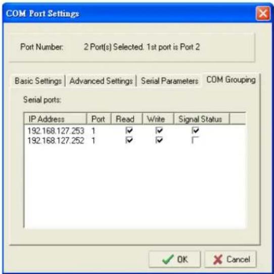
- Click OK, and confirm that the serial ports were assigned. The COM Port column confirms that your selected ports are labeled as part of a "Group." You will be able to view the serial ports that were assigned to and removed from the Group. Click Apply to apply the settings.
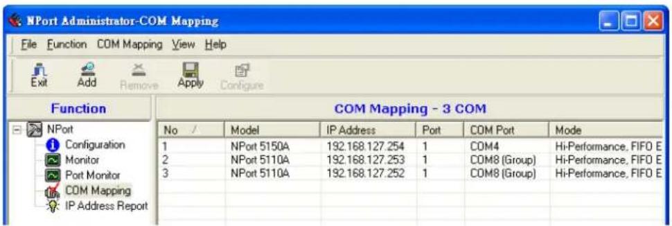
- Finally, click Yes to confirm.

Deleting a COM Group
Follow the steps below to delete a COM Group and then auto-assign COM numbers for each port in the Group:
- Select all serial ports in the Group you are deleting and then right-click to select COM Settings.
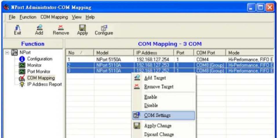
- Select a COM number for this COM group and check the Auto enumerating COM number for selected ports to use the COM number you select as the first starting COM number, and then click OK.
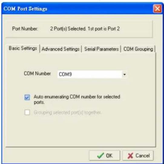
- You will be able to view the serial ports that were assigned to and removed from the Group. Click Apply to apply the settings.
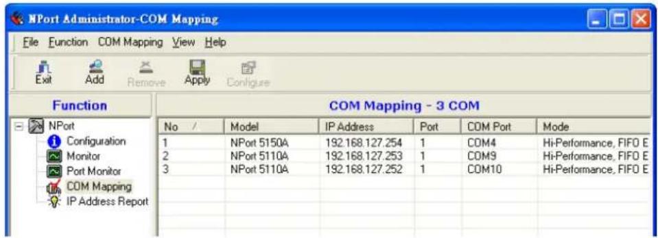
- Finally, click Yes to confirm.

Adding a Port to a COM Group
Follow the steps below to add a serial port into an existing COM Group:
- Select the serial port that you are adding and right-click to select COM Settings.
![NPort Administrator-COM Mapping File Function COM Mapping View Help Exit Add Remove Apply Configure Function COM Mapping - 5 COM No / Model IP Address Port COM Port Mode 1 NPort 5150A 192.168.127.254 1 COM4 HiPerformance, FIFO Env 2 NPort 5110A 192.168.127.253 1 COM8 [Group] HiPerformance, FIFO Env 3 NPort 5110A 192.168.127.252 1 COM8 [Group] HiPerformance, FIFO Env 4 NPort 5210A 192.168.127.250 1 COM6 HiPerformance, FIFO Env 5 NPort 5210A 192.168.127.250 1 COM7 HiPerformance, FIFO Env Add Target Remove Target Enable Disable COM Settings Apply Change Discard Change](/content/2026/06/1274135/images/9060bc9ec667cfea2dad071bbfdd7b0e0b78d1fddb51e647b8e0ad4c4555cfae.jpg)
- Select the COM number of the COM Group you are adding and check mark the Grouping selected port(s) together check box and then click OK.
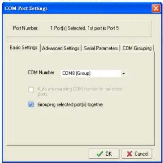
- You will be able to view the serial ports that were assigned to and removed from the Group. Click Apply to apply the settings.
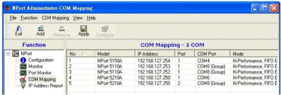
- Finally, click Yes to confirm.

Removing a Port from a COM Group
Follow the steps below to remove a serial port from a COM Group:
- Select a serial port in the Group and right-click to select COM Settings.
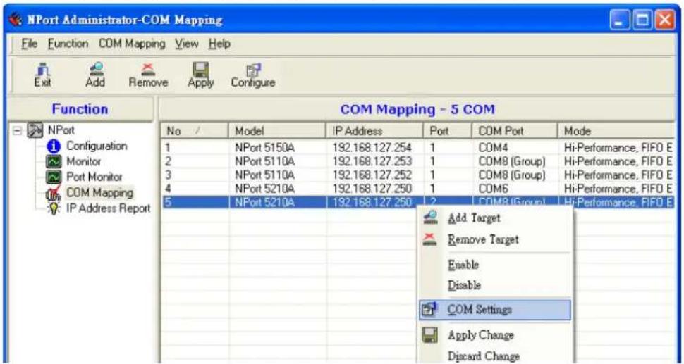
- Select a COM number that is not in use or assigned to a Group and click OK.
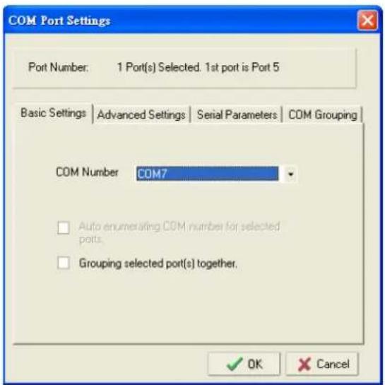
- You will be able to view the serial ports that were assigned to and removed from the Group. Click Apply to apply the settings.
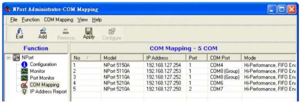
- Finally, click Yes to confirm.

Modify Ports in a COM Group
In the following subsections we examine three ways in which the serial ports in a COM Group can be modified:
Changing the COM Number of a COM Group
- Select all serial ports in the Group and right-click to select COM Settings.
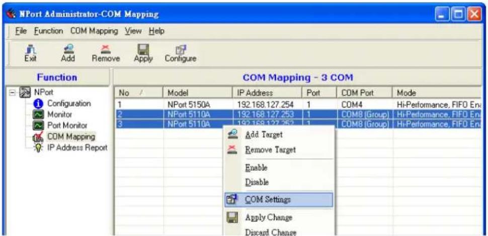
- Select a COM number that is not in use or assigned to a Group.
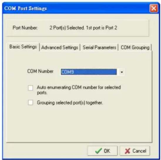
- Select the Grouping selected port(s) together checkbox and then click OK.
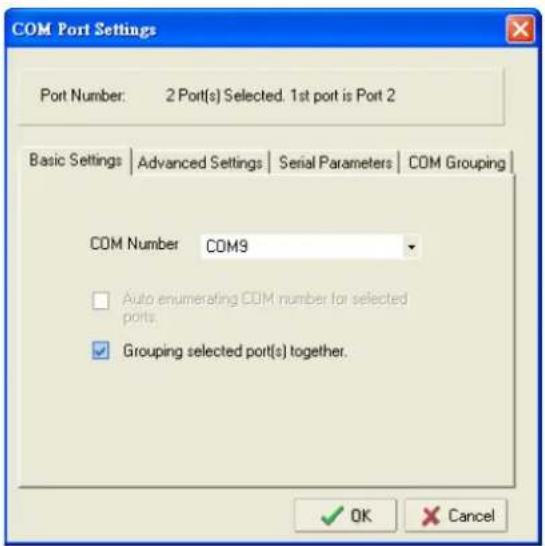
- You will be able to view the serial ports that were assigned to and removed from the Group. Click Apply to apply the settings.
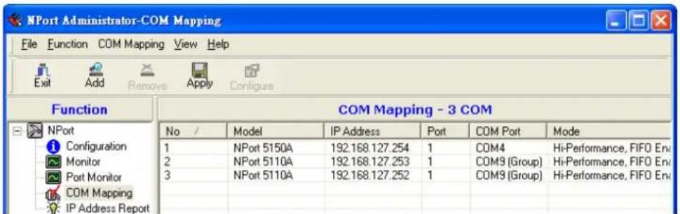
- Finally, click Yes to confirm.

Changing Advanced Settings and Serial Parameters of the COM Group
- Check the port specified on the COM Grouping page as the signal port.
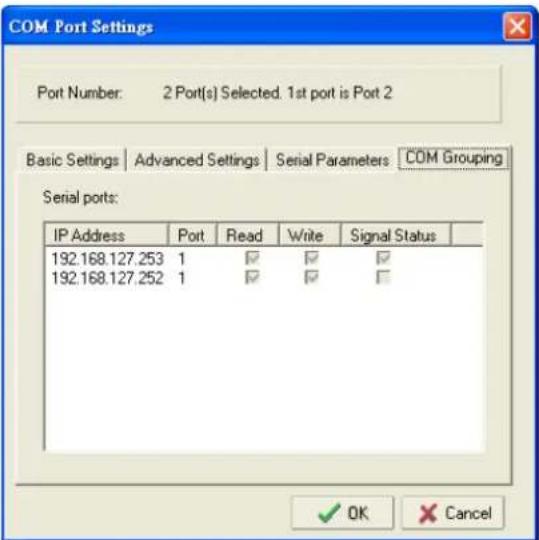
- Select the "Signal Status" controlled port and then right-click and select COM Settings.
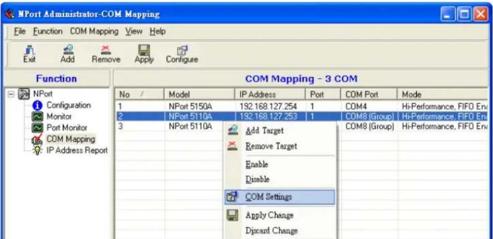
- The Advanced Settings and Serial Parameters pages will be available for modification.
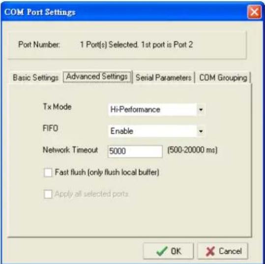
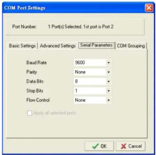
Changing the Serial Port Specified as Signal Port for the COM Group
- Select a serial port in the Group and then right-click and select COM Settings.
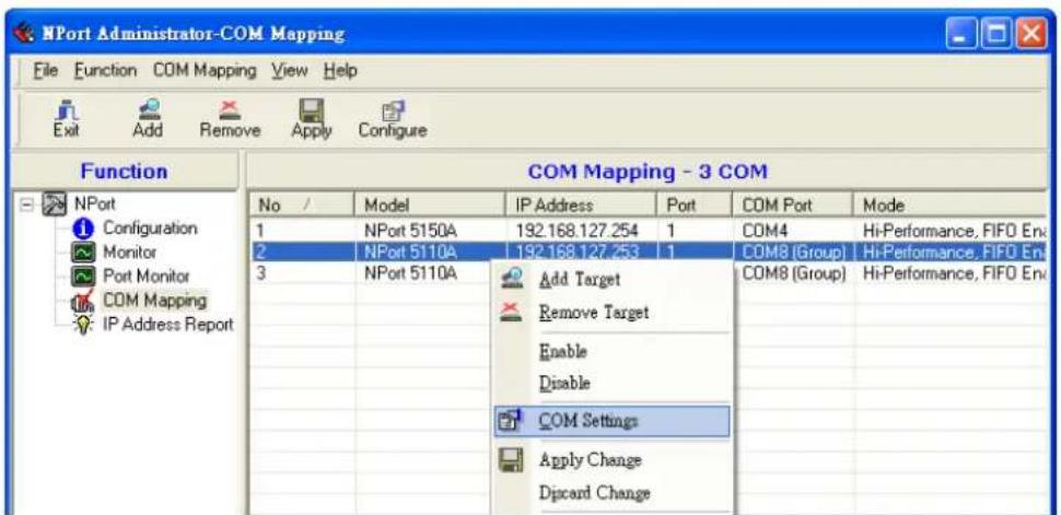
- Check the Grouping selected port(s) together check box.
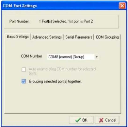
- On the COM Grouping page, you can specify one serial port whose signals will be taken into account by the COM Group and change the Read/Write status for each serial port.
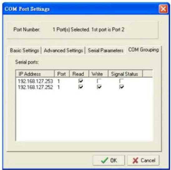
IP Address Report
When an NPort 5100A is used in a dynamic IP environment, users must spend more time with IP management tasks. NPort 5100A Series products periodically report their IP address to the IP location server, in case the dynamic IP has changed.
- Configure the NPort 5100A with Dynamic IP settings (DHCP, BOOTP, or DHCP/BOOTP). Assign the remote Auto IP report server's IP address and UDP port.
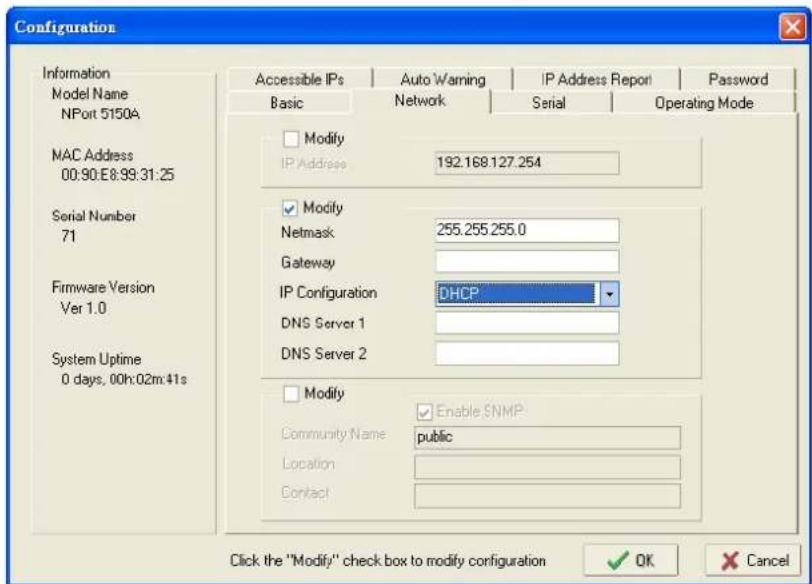
- Select the IP Address Report, and click the right mouse button to select Settings.
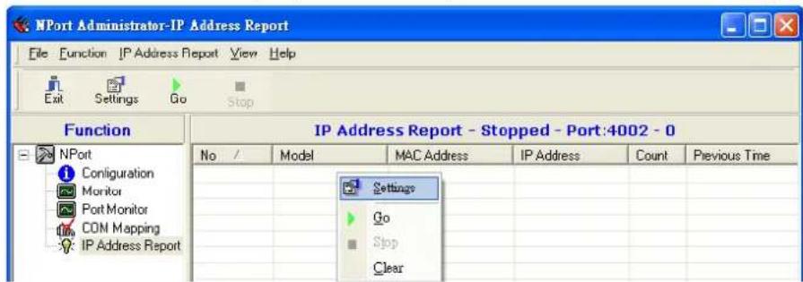
- Configure the Local Listen Port to be the same as the NPort 5100A's "Auto report to UDP port" setting.
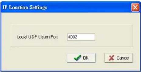
- Click Go to start receiving the Auto IP address report from the NPort 5100A.
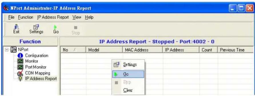
The following topics are covered in this chapter:
Overview
What is IP Serial Library?
Why Use IP Serial Library?
How to Install IP Serial Library
☐ IP Serial LIB Function Groups
□ Sample Program
Overview
What is IP Serial Library?
IP Serial Library is a Windows library with frequently used serial command sets and subroutines. IP Serial Library is designed to reduce the complexity and poor efficiency of serial communication over TCP/IP. For example, Telnet can only transfer data, but it can't monitor or configure the serial line's parameters.
Why Use IP Serial Library?
For programmers familiar with serial communication, IP Serial Library provides well-designed function calls that have the same style as Moxa's PComm Library.
IP Serial Library is amazingly simple and easy to understand. By including it in your VB, C, or Delphi programming environment, you can program your own TCP/IP application with the ability to control serial communication parameters.
The NPort 5100A uses 2 TCP ports for communication between the NPort 5100A and host computer's Real COM driver. The NPort 5100A uses a data port and command port to provide pure data transfer without decode and encode. Compared to using only one TCP port to control serial communication (such as RFC 2217), IP Serial Library uses a command port to communicate with the NPort 5100A from the user's program. IP Serial Library not only runs with excellent efficiency but also runs without any decode or encode problems.
How to Install IP Serial Library
IP Serial Lib comes with the NPort Administration Suite. Refer to the IPSerial directory for more detail about the function definitions.
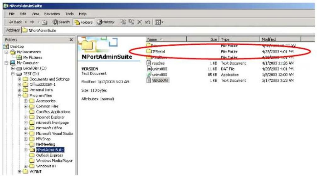
IP Serial LIB Function Groups
| Server Control | Port Control | Input/Output Data | Port Status Inquiry | Miscellaneous |
| nsio_init | nsio_open | nsio_read | nsio_Istatus | nsio_break |
| nsio_end | nsio_close | nsio_SetReadTimeouts | nsio_data_status | nsio_break_on |
| nsio_resetserver | nsio_ioctl | nsio_write | nsio_break_off | |
| nsio_checkalive | nsio_flowctrl | nsio_SetWriteTimeouts | nsio_breakcount | |
| nsio_DTR | ||||
| nsio_RTS | ||||
| nsio_lctrl | ||||
| nsio_baud | ||||
| nsio_resetport |
Sample Program
char NPort 5100A-Nip="192.168.1.10";
char buffer[255];    /*data buffer, 255 chars */
int port = 1;    /*1st port */
int portid;    /* port handle */
nsio_init();    /*initial IP Serial Library */
portid = nsio_open(NPort 5100Aip, port);    /*1st port, NPort 5100A IP=192.168.1.10 */
nsio_ioctl(portid, B9600, (BIT_8 | STOP_1 | P_NONE));/*set 9600, N81 */
sleep(1000);    /* wait for 1000 ms for data */
nsio_read(port, buffer, 200);    /* read 200 bytes from port 1 */
nsio_close(portid);    /* close this serial port */
nsio_end();    /* close IP Serial Library */
The following topics are covered in this appendix:
□ Port Pinout Diagrams
Ethernet Port Pinouts
➢ NPort 5110A Serial Port Pinouts
NPort 5130A Serial Port Pinouts
NPort 5150A/P5150A Serial Port Pinouts
□ Cable Wiring Diagrams
Ethernet Cables
Port Pinout Diagrams
Ethernet Port Pinouts
| Pin Signal | |
| 1 Tx+ | |
| 2 Tx- | |
| 3 Rx+ | |
| 6 Rx- | |
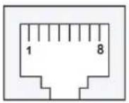
NPort 5110A Serial Port Pinouts
DB9 Male RS-232 Port Pinouts for NPort 5110A
| Pin RS-232 | |
| 1 DCD | |
| 2 RxD | |
| 3 TxD | |
| 4 DTR | |
| 5 GND | |
| 6 DSR | |
| 7 RTS | |
| 8 CTS | |
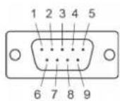
NPort 5130A Serial Port Pinouts
DB9 Male RS-422/485 Port Pinouts for the NPort 5130A
| Pin | RS-422 / 4-wire RS-485 | 2-wire RS-485 |
| 1 TxD-(A) - | ||
| 2 TxD+(B) - | ||
| 3 RxD+(B) Data+(B) | ||
| 4 | RxD-(A) | Data-(A) |
| 5 GND | GND | |
| 6 -- | ||
| 7 -- | ||
| 8 -- |
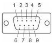
NPort 5150A/P5150A Serial Port Pinouts
DB9 Male RS-232/422/485 Port Pinouts for the NPort 5150A
| Pin | RS-232 | RS-422 / 4-wire RS-485 | 2-wire RS-485 |
| 1 DCD | TxD-(A) - | ||
| 2 RxD | TxD+(B) - | ||
| 3 TxD | RxD+(B) Data +(B) | ||
| 4 | DTR | RxD-(A) | Data-(A) |
| 5 GND | GND GND | ||
| 6 DSR | - | - | |
| 7 RTS | - | - | |
| 8 CTS | - | - |
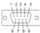
Cable Wiring Diagrams
Ethernet Cables
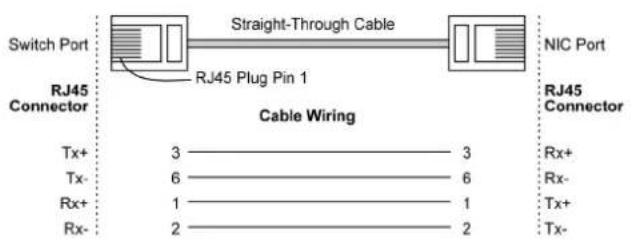
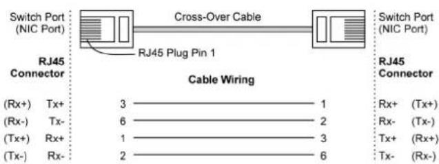
In this appendix, which is included for your reference, we provide a list of Well Known port numbers that may cause network problems if you set the NPort 5100A to one of these ports. Refer to RFC 1700 for Well Known port numbers, or refer to the following introduction from the IANA.
The port numbers are divided into three ranges: the Well Known Ports, the Registered Ports, and the Dynamic and/or Private Ports.
The Well Known Ports range from 0 through 1023.
The Registered Ports range from 1024 through 49151.
The Dynamic and/or Private Ports range from 49152 through 65535.
The Well Known Ports are assigned by the IANA, and on most systems, can only be used by system processes or by programs executed by privileged users. The following table shows famous port numbers among the well-known port numbers. For more details, please visit the IANA website at
http://www.iana.org/assignments/port-numbers.
| TCP Socket | Application Service |
| 0 Reserved | |
| 1 TCP Port Service Multiplexer | |
| 2 Management Utility | |
| 7 Echo | |
| 9 Discard | |
| 11 Active Users (systat) | |
| 13 Daytime | |
| 15 Netstat | |
| 20 FTP data port | |
| 21 FTP CONTROL port | |
| 23 Telnet | |
| 25 SMTP (Simple Mail Transfer Protocol) | |
| 37 Time (Time Server) | |
| 42 Host name server (names server) | |
| 43 Whois (nickname) | |
| 49 (Login Host Protocol) (Login) | |
| 53 Domain Name Server (domain) | |
| 79 Finger protocol (Finger) | |
| 80 World Wide Web HTTP | |
| 119 | Network News Transfer Protocol (NNTP) |
| 123 Network Time Protocol | |
| 213 IPX | |
| 160 - 223 Reserved for future use | |
| UDP Socket Application Service | |
| 0 Reserved | |
| 2 Management Utility | |
| 7 Echo | |
| 9 Discard | |
| 11 Active Users (systat) | |
| 13 Daytime | |
| 35 Any private printer server | |
| 39 Resource Location Protocol | |
| 42 Host name server (names server) | |
| 43 Whois (nickname) | |
| 49 (Login Host Protocol) (Login) | |
| 53 Domain Name Server (domain) | |
| 69 Trivial Transfer Protocol (TETP) | |
| 70 Gopher Protocol | |
| 79 Finger Protocol | |
| 80 World Wide Web HTTP | |
| 107 Remote Telnet Service | |
| 111 Sun Remote Procedure | Call (Sunrpc) |
| 119 | Network News Transfer Protocol (NNTP) |
| 123 | Network Time Protocol (NTP) |
| 161 SNMP (Simple Network | Mail Protocol) |
| 162 SNMP Traps | |
| 213 IPX (Used for IP Tunneling) | |
SNMP Agents with MIB II & RS232/422/485 Link Groups
The NPort 5100A has a built-in SNMP (Simple Network Management Protocol) software agent that supports SNMP Trap, RFC1317 RS-232/422/485 like groups, and RFC 1213 MIB-II. The following table lists the standard MIB-II groups, as well as the variables implemented for the NPort 5100A.
RFC1213 MIB-II Supported SNMP Variables
| System MIB | Interfaces MIB | IP MIB | ICMP MIB |
| SysDescr | itNumber | ipForwarding | IcmpInMsgs |
| SysObjectID | ifIndex | ipDefaultTTL | IcmpInErrors |
| SysUpTime | ifDescr | ipInreceives | IcmpInDestUnreachs |
| SysContact | ifType | ipInHdrErrors | IcmpInTimeExcds |
| SysName | ifMtu | ipInAddrErrors | IcmpInParmProbs |
| SysLocation | ifSpeed | ipForwDatagrams | IcmpInSrcQuenchs |
| SysServices | ifPhysAddress | ipInUnknownProtos | IcmpInRedirects |
| ifAdminStatus | ipInDiscards | IcmpInEchos | |
| ifOperStatus | ipInDelivers | IcmpInEchoReps | |
| ifLastChange | ipOutRequests | IcmpInTimestamps | |
| ifInOctets | ipOutDiscards | IcmpTimestampReps | |
| ifInUcastPkts | ipOutNoRoutes | IcmpInAddrMasks | |
| ifInNUcastPkts | ipReasmTimeout | IcmpOutMsgs | |
| ifInDiscards | ipReasmReqds | IcmpOutErrors | |
| ifInErrors | ipReasmOKs | IcmpOutDestUnreachs | |
| ifInUnknownProtos | ipReasmFails | IcmpOutTimeExcds | |
| ifOutOctets | ipFragOKs | IcmpOutParmProbs | |
| ifOutUcastPkts | ipFragFails | IcmpOutSrcQuenchs | |
| ifOutNUcastPkts | ipFragCreates | IcmpOutRedirects | |
| ifOutDiscards | ipAdEntAddr | IcmpOutEchos | |
| ifOutErrors | ipAdEntIfIndex | IcmpOutEchoReps | |
| ifOutQLen | ipAdEntNetMask | IcmpOutTimestamps | |
| ifSpecific | ipAdEntBcastAddr | IcmpOutTimestampReps | |
| ipAdEntReasmMaxSize | IcmpOutAddrMasks | ||
| IpNetToMediaIfIndex | IcmpOutAddrMaskReps | ||
| IpNetToMediaPhysAddress | |||
| IpNetToMediaNetAddress | |||
| IpNetToMediaType | |||
| IpRoutingDiscards |
| UDP MIB TCP MIB SNMP MIB | ||
| UdpInDatagrams | tcpRtoAlgorithm | snmpInPkts |
| UdpNoPorts | tcpRtoMin | snmpOutPkts |
| UdpInErrors | tcpRtoMax | snmpInBadVersions |
| UdpOutDatagrams | tcpMaxConn | snmpInBadCommunityNames |
| UdpLocalAddress | tcpActiveOpens | snmpInASNParseErrs |
| UdpLocalPort tcpPassiveOpens snmpInTooBigs | ||
| tcpAttemptFails | snmpInNoSuchNames | |
| Address Translation MIB | tcpEstabResets | snmpInBadValues |
| AtIfIndex | tcpCurrEstab | snmpInReadOnly |
| AtPhysAddress | tcpInSegs | snmpInGenErrs |
| AtNetAddress | tcpOutSegs | snmpInTotalReqVars |
| AtNetAddress | tcpRetransSegs | snmpInTotalSetVars |
| tcpConnState | snmpInGetRequests | |
| tcpConnLocalAddress | snmpInGetNexts | |
| tcpConnLocalPort | snmpInSetRequests | |
| tcpConnRemAddress | snmpInGetResponses | |
| tcpConnRemPort snmpInTraps | ||
| tcpInErrs | snmpOutTooBigs | |
| tcpOutRsts | snmpOutNoSuchNames | |
| snmpOutBadValues | ||
| snmpOutGenErrs | ||
| snmpOutGetRequests | ||
| snmpOutGetNexts | ||
| snmpOutSetRequests | ||
| snmpOutGetResponses | ||
| snmpOutTraps | ||
| snmpEnableAuthenTraps | ||
RFC1317: RS-232/422/485 MIB Objects
| Generic RS-232/422/485-like Group | RS-232/422/485-like General Port Table | RS-232/422/485-like Asynchronous Port Group |
| rs232Number | rs232PortTable | rs232AsyncPortTable |
| rs232PortEntry | rs232AsyncPortEntry | |
| rs232PortIndex | rs232AsyncPortIndex | |
| rs232PortType | rs232AsyncPortBits | |
| rs232PortInSigNumber | rs232AsyncPortStopBits | |
| rs232PortOutSigNumber | rs232AsyncPortParity | |
| rs232PortInSpeed | ||
| rs232PortOutSpeed |
| Input Signal Table | Output Signal Table |
| rs232InSigTable | rs232OutSigTable |
| rs232InSigEntry | rs232OutSigEntry |
| rs232InSigPortIndex | rs232OutSigPortIndex |
| rs232InSigName | rs232OutSigName |
| rs232InSigState | rs232OutSigState |
The NPort Series provides several ways to configure Ethernet IP addresses. One of them is DHCP Client. When you set up the NPort to use DHCP Client to configure Ethernet IP addresses, it will automatically send a DHCP request over the Ethernet to find the DHCP Server. And then the DHCP Server will send an available IP address to the NPort. The NPort will use this IP address for a period of time after receiving it. But the NPort will send a DHCP request again to the DHCP Server. Once the DHCP Server realizes that this IP address is to be released to another DHCP Client, the NPort then will receive a different IP address. For this reason, users sometimes find that the NPort will use different IP addresses, not a fixed IP address.
In order to know what IP address the NPort is using, you need to set up parameters in Network Settings via the Web browser. The figure below is the NPort Web console configuration window. Enter the IP address and the Port number of the PC that you want to send this information to.
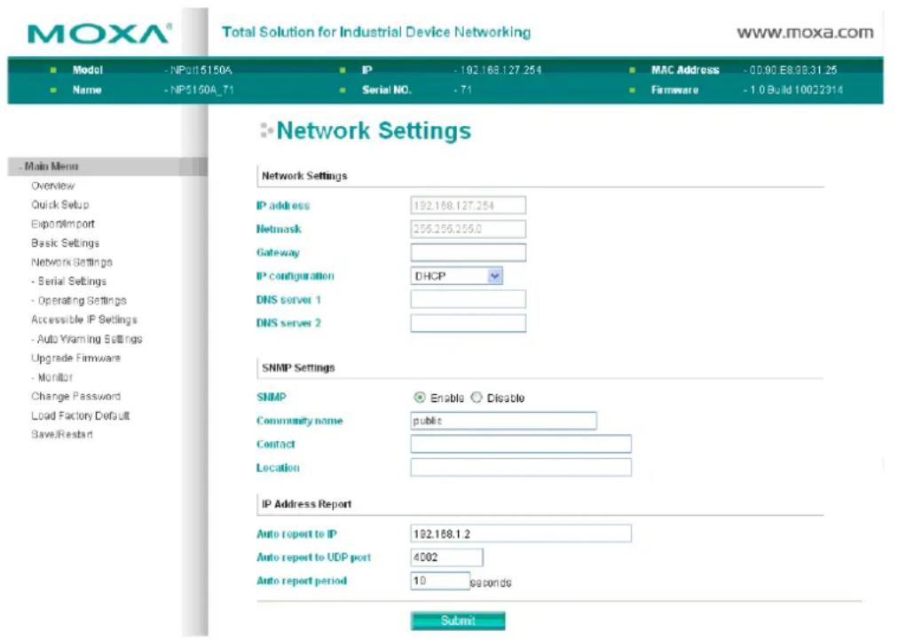
Auto IP Report Format
| "Moxa", 4 bytes | Info[0] | Info[1] | ... | Info[n] |
Info [n]
| Field | ID | Length | Data |
| Length | 1 | 1 | Variable, Length is "Length Field" |
ID List
| ID Value | Description | Length | Note |
| 1 Server Name | Variable ASCII char | ||
| 2 Hardware ID | 2 Little-endian | ||
| 3 MAC Address | 6 6 bytes MAC address. If the MAC address is "00-90-E8-01-02-03", the MAC[0] is 0, MAC[1] is 0x90(hex), MAC[2] is 0xE8(hex), and so on. | ||
| 4 | Serial Number | 4, DWORD | Little-endian |
| 5 | IP Address | 4, DWORD | Little-endian |
| 6 | Netmask | 4, DWORD | Little-endian |
| 7 | Default Gateway | 4, DWORD | Little-endian |
| 8 | Firmware Version | 4, DWORD | Little-endianVer1.3.4= 0x0103040 |
| 9 | AP ID | 4, DWORD | Little-endian |
This is a Class A product. In a domestic environment, this product may cause radio interference, in which case the user may be required to take appropriate measures.
Federal Communications Commission Statement
This device complies with part 15 of the FCC Rules. Operation is subject to the following two conditions: (1) This device may not cause harmful interference, and (2) this device must accept any interference received, including interference that may cause undesired operation.

FCC Warning
This equipment has been tested and found to comply with the limits for a Class A digital device, pursuant to part 15 of the FCC Rules. These limits are designed to provide reasonable protection against harmful interference when the equipment is operated in a commercial environment. This equipment generates, uses, and can radiate radio frequency energy and, if not installed and used in accordance with the instruction manual, may cause harmful interference to radio communications. Operation of this equipment in a residential area is likely to cause harmful interference, in which case the user will be required to correct the interference at his or her own expense.
- NPort 5100A Series Users Manual
- Copyright Notice
- Trademarks
- Disclaimer
- Technical Support Contact Information
- Moxa Americas
- Moxa Europe
- Moxa India
- Moxa China (Shanghai office)
- Moxa Asia-Pacific
- Getting Started 2-1
- Initial IP Address Configuration.... 3-1
- Choosing the Proper Operation Mode 4-1
- Web Console Configuration 5-1
- Auto IP Report Protocol ....D-1
- Compliance Notice.... E-1
- Overview
- Package Checklist
- Standard Accessories
- Optional Accessories
- Product Features
- Product Specifications
- Ethernet Interface
- Serial Interface
- Serial Standards:
- Serial Communication Parameters
- Serial Signals
- Software
- Physical Characteristics
- Environmental Limits
- Operating Temperature:
- Power Requirements
- Power Consumption:
- Standards and Certifications
- Power Line Protection:
- Reliability
- Warranty
- □ Panel Layouts
- □ Connecting the Hardware
- Panel Layouts
- Connecting the Hardware
- Connecting the Power
- NPort P5150A
- NPort 5150A/5130A/5150A
- Connecting to the Network
- Connecting to a Serial Device
- LED Indicators
- Adjustable Pull High/Low Resistor for the RS-485 Port
- NPort 5130A/5150A Jumpers
- ATTENTION
- Initializing the NPort 5100A's IP Address
- Factory Default IP Address
- NPort Administration Suite
- ARP
- Telnet Console
- Serial Console (19200, n, 8, 1) (NPort 5110A/5150A/P5150A only)
- Real COM Mode
- RFC 2217 Mode
- TCP Server Mode
- TCP Client Mode
- UDP Mode
- Pair Connection Mode
- Ethernet Modem Mode
- Reverse Telnet Mode
- Disabled Mode
- Opening Your Browser
- Quick Setup
- Export/Import
- Basic Settings
- Web/Telnet Console
- Network Settings
- SNMP Settings
- IP Address Report
- Serial Settings
- Serial Parameters
- Operating Settings
- UDP Multicast
- Pair Connection Master Mode
- Pair Connection Slave Mode
- Dial-in
- ATS0=0 (default):
- ATS0≥1:
- Dial-out
- Disconnection Request from the Local Site
- Disconnection Request from the Remote Site
- AT Commands
- S Registers
- Accessible IP Settings
- Auto Warning Settings
- Auto warning: Email and SNMP trap
- Mail Server
- SNMP Trap Server
- Event Type
- Cold start
- Warm start
- Authentication failure
- IP address changed
- Password changed
- DCD changed
- DSR changed
- Upgrade Firmware
- Monitor
- Monitor Line
- Monitor Async
- Monitor Async-Settings
- Change Password
- Load Factory Default
- Installing NPort Administrator
- Configuration
- Broadcast Search
- Unlock Password Protection
- Lock
- Unlock
- Blank
- Fixed
- Lock Fixed
- Unlock Fixed
- Configuring the NPort 5100A
- Upgrading the Firmware
- Export Configuration
- Import Configuration
- Initiating the Monitor Function
- Using the Monitor Function
- Port Monitor
- COM Mapping
- On-line COM Mapping
- Fast Flush (only flush local buffer)
- COM Grouping
- Creating a COM Group
- Deleting a COM Group
- Adding a Port to a COM Group
- Removing a Port from a COM Group
- Modify Ports in a COM Group
- Changing the COM Number of a COM Group
- Changing Advanced Settings and Serial Parameters of the COM Group
- Changing the Serial Port Specified as Signal Port for the COM Group
- What is IP Serial Library?
- Why Use IP Serial Library?
- How to Install IP Serial Library
- IP Serial LIB Function Groups
- Sample Program
- □ Port Pinout Diagrams
- □ Cable Wiring Diagrams
- Port Pinout Diagrams
- Ethernet Port Pinouts
- NPort 5110A Serial Port Pinouts
- DB9 Male RS-232 Port Pinouts for NPort 5110A
- NPort 5130A Serial Port Pinouts
- DB9 Male RS-422/485 Port Pinouts for the NPort 5130A
- NPort 5150A/P5150A Serial Port Pinouts
- DB9 Male RS-232/422/485 Port Pinouts for the NPort 5150A
- Cable Wiring Diagrams
- Ethernet Cables
- SNMP Agents with MIB II & RS232/422/485 Link Groups
- Auto IP Report Format
- Info [n]
- Federal Communications Commission Statement
- FCC Warning
Brand : Moxa
Model : 5150A-T
Category : Server