
Digital Multimeter PDMT25 - Multimeter Pyle - Free user manual and instructions
Find the device manual for free Digital Multimeter PDMT25 Pyle in PDF.


| Product Type | Digital Multimeter |
| Brand | Pyle |
| Model | PDMT25 |
| Dimensions | Approximately 7.0 x 3.5 x 1.5 inches |
| Weight | About 0.5 lb (including battery) |
| Power Supply | 1 x 9V battery (NEDA 1604A) |
| Display | LCD with 2000 counts |
| DC Voltage Range | 200mV, 2V, 20V, 200V, 600V |
| AC Voltage Range | 2V, 20V, 200V, 600V |
| DC Current Range | 200μA, 2mA, 20mA, 200mA, 10A |
| Resistance Range | 200Ω, 2kΩ, 20kΩ, 200kΩ, 2MΩ, 20MΩ |
| Diode Test | Yes |
| Continuity Test | Yes (buzzer) |
| Transistor Test | Yes (hFE) |
| Backlight | Yes |
| Data Hold | Yes |
| Low Battery Indication | Yes |
| Safety Rating | CAT II 600V |
| Operating Temperature | 32°F to 104°F (0°C to 40°C) |
| Storage Temperature | 14°F to 122°F (-10°C to 50°C) |
| Accessories Included | Test leads, 9V battery, user manual |
| Maintenance | Clean with a damp cloth; avoid solvents; replace battery when low. |
| Spare Parts Availability | Standard 9V battery and common test leads; contact Pyle support for specifics. |
Frequently Asked Questions - Digital Multimeter PDMT25 Pyle
User questions about Digital Multimeter PDMT25 Pyle
0 question about this device. Answer the ones you know or ask your own.
Ask a new question about this device
Download the instructions for your Multimeter in PDF format for free! Find your manual Digital Multimeter PDMT25 - Pyle and take your electronic device back in hand. On this page are published all the documents necessary for the use of your device. Digital Multimeter PDMT25 by Pyle.
USER MANUAL Digital Multimeter PDMT25 Pyle
OPERATING INSTRUCTIONS AUTORANGING DIGITAL MULTIMETER
PDMT25

www.pyleaudio.com

SAFETY WARNINGS
The following safety information must be observed to insure maximum personal safety during the operation at this meter:
- Measurements beyond the maximum selected range must not be attempted.
- Extreme care must be taken when measuring above 50 V, especially on live bus-bars.
- To measure voltage, the instrument must not be switched to a current or resistance range, or to the diode check or buzzer position.
- Circuits must be de-energised and isolated before carrying out resistance tests.
- The rotary selector switch must only be turned after removing test connections.
- All external voltages must be disconnected from the instrument before removing the battery.
- Test leads and prods must be in good order, clean, and with no broken or cracked insulation.
- UK Safety Authorities recommend the use of fused test leads when measuring voltage on high energy systems.
- Replacement fuses must be of the correct type and rating.
- The instrument must not be used if any part of it is damaged.
- Warnings and precautions must be read and understood before an instrument is used. They must be observed during the operation of this instrument.
Symbols used on this instrument are:

Caution: refer to accompanying notes.
This symbol indicates that the operator must refer to an explanation in the Operating Instructions to avoid personal injury or damage to the meter.

Caution: risk of electric shock
This WARNING symbol indicates a potentially hazardous situation, which if not avoided, could result in death or serious injury.

This CAUTION symbol indicates a potentially hazardous situation, which if not avoided, may result damage to the product.
This symbol advises the user that the terminal(s) so marked must not be connected to a circuit point at which the voltage with respect to earth ground exceeds (in this case) 1000 VAC or VDC.

Equipment protected throughout by Double Insulation (Class II)

Equipment complies with current EU directives.
SYMBOLS AND ANNUNCIATORS
•))))
Continuity
BAT
Low
Battery

Diode
test
HOLD
Data
Hold
AUTO
AutoRanging
AC Alternating Current or Voltage
DC Direct Current or Voltage
MAX/MIN Stores the highest or lowest measurement
PEAK Find glitches and transients without a scope

Backlight
V
Volts
A, mA, uA
Current range
OPERATION
To turn on the instrument turn the range knob from the OFF position to any measurement range.
Note:
For best battery life ALWAYS turn the function switch to the OFF position when the meter is not in use. This meter has Auto OFF that automatically shuts the meter OFF if 30 minutes elapse between uses.
NOTE: On some low AC and DC voltage ranges, with the test leads not connected to a device, the display may show a random, changing reading. This is normal and is caused by the high-input sensitivity. The reading will stabilize and give a proper measurement when connected to a circuit.
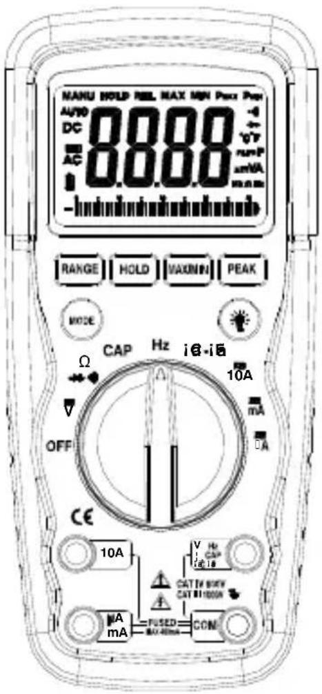
MODE button
To select AC or DC measurement when in Voltages, Amps, mA, uA, Ω, ▶+, •)) ) , °C or °Franges.
HOLD button
The HOLD function allows the meter to "freeze" a
measurement for later reference.
- Press the HOLD button to “freeze” the reading on the indicator. The “HOLD” message will be appear in the display.
- Press the HOLD button again to return to normal operation.
BACKLIGHT button
- Press the BACKLIGHT button to switch on the display light.
- Press BACKLIGHT button again to exit the light mode.
MAX/MIN button
The MAX/MIN function allows the meter to capture the highest or lowest measurement for later reference.
- Press the MAX/MIN button to begin measurement. The indicator “MAX” or MIN will appear in the display.
- If the “MAX MIN” messages are flashing, the instrument is in MAX/MIN mode but not recording, press the MAX/MIN button to select a mode.
- To return to normal AUTO measurement mode, hold down the MAX/MIN button for 2 seconds.
Peak Hold button
The Peak Hold function captures the peak AC or DC voltage or current. The meter can capture negative or positive peaks as fast as 1 millisecond in duration.
- Turn the function switch to the A or V position.
- Use the MODE button to select AC or DC.
- Allow time for the display to stabilize.
- Press and Hold the PEAK button until "CAL" appears in the display. This procedure will zero the range selected.
- Press the PEAK button, Pmax will display.
- The display will update each time a higher positive peak occurs.
- Press the PEAK button again, Pmin will display. The display will now update and indicate the lowest negative peak.
- To return to normal operation, press and hold the PEAK button until the Pmin or Pmax indicator switches off.
Note: If the Function switch position is changed after a calibration the Peak Hold calibration must be repeated
for the new function selected.
RANGE button
When the meter is first turned on, it automatically goes into AutoRanging. This automatically selects the best range for the measurements being made and is generally the best mode for most measurements. For measurement situations requiring that a range be manually selected, perform the following:
- Press the RANGE button. The “Auto Range” display indicator will turn off, The “Manual Range” display indicator will turn on
- Press the RANGE button to step through the available ranges until you select the range you want.
- Press and hold the RANGE button for 2 seconds to exit the ManualRanging mode and return to AutoRanging.
4.
DC/DC VOLTAGE MEASUREMENT
- sert the black test lead into the negative COM terminal and the red test lead into the positive V terminal.
- Set the function switch to the V_AC or V_DC position.
- Use the MODE button to select AC or DC Voltage
- Connect the test leads in parallel to the circuit under test.
- Read the voltage measurement on the LCD display
DC CURRENT MEASUREMENT
- Insert the black test lead banana plug into the negative (COM) jack.
- For current measurements up to 4000uA DC, set the function switch to the uA position and insert the red test lead banana plug into the (uA) jack.
- For current measurements up to 400mA DC, set the function switch to the mA range and insert the red test lead banana plug into the (mA) jack.
- For current measurements up to 10A DC, set the function switch to the A position and insert the red
test lead banana plug into the 10A jack.
- Press the AC/DC button until “DC” appears in the display.
- Remove power from the circuit under test, then open up the circuit at the point where you wish to measure current.
- Touch the black test probe tip to the negative side of the circuit. Touch the red test probe tip to the positive side of the circuit.
- Apply power to the circuit.
- Read the current in the display. The display will indicate the proper decimal point, value and symbol.
AC CURRENT MEASUREMENT
- Insert the black test lead plug into the negative (COM) socket.
- For current measurements up to 10A, set the function switch to the A position and insert the red test lead plug into the (10A) jack.
- For current measurements up to 400mA, set the function switch to the mA range and insert the red test lead banana plug into the (mA) jack.
- For current measurements up to 10A AC, set the function switch to the A position and insert the red test lead banana plug into the 10A jack.
- Press the MODE button. The measurement mode will change between AC or DC as required.
- Remove power from the circuit under test, then open up the circuit at the point where you wish to measure current.
- Touch the black test probe tip to the negative side of the circuit. And touch the red test probe tip to the positive side of the circuit.
- Apply power to the circuit.
- Read the current in the display. The display will
indicate the proper decimal point, value and symbol.
RESISTANCE [Ω] MEASUREMENT
WARNING: To avoid electric shock, disconnect power to the unit under test and discharge all capacitors before taking any resistance measurements. Remove the batteries and unplug the line cords.
- Set the function switch to the position.
- Insert the black test lead plug into the negative (COM) socket and the red test lead plug into the positive jack.
- Press the MODE button until “Ω” appears in the display.
- Touch the test probe tips across the circuit or part under test. It is best to disconnect one side of the part under test so the rest of the circuit will not interfere with the resistance reading.
- Read the resistance in the display. The display will indicate the proper decimal point, value and symbol.
CONTINUITY CHECK
WARNING: To avoid electric shock, never measure continuity on circuits or wires that have voltage on them.
- Set the range switch to the •))) position.
- Insert the black lead plug into the COM socket and the red test lead plug into the positive •))) socket.
- Press the MODE button until “•)))” appears in the display.
- Touch the test probe tips to the circuit or wire you wish to check.
- If the resistance is less than 35 , the audible signal will sound. The display will also show the actual resistance in ohms.
DIODE TEST
WARNING: To avoid electric shock, do not test any diode that has voltage on it.
- Set the function switch to the position.
- Insert the black test lead plug into the COM socket and the red test lead plug into the ▶ socket.
- Press the MODE button until “▶” appears in the display.
- Touch the test probe tips to the diode or semiconductor junction you wish to test. Note the meter reading.
- Reverse the probe polarity by switching probe position. Note this reading.
- The diode or junction can be evaluated as follows:
A. If one reading shows a value and the other reading shows OL, the diode is good.
B. If both readings show OL, the device is open.
C. If both readings are very small or zero, the device is shorted.
NOTE: The value indicated in the display during the diode check is the forward voltage.
CAPACITANCE MEASUREMENT
WARNING: To avoid electric shock, discharge the capacitor under test before measuring.
- Set the function switch to the CAP capacitance position.
- Insert the black test lead banana plug into the negative COM jack and the red test lead banana plug into the CAP positive jack.
- Touch the test probe tips across the part under test.
- Read the capacitance value in the display.
- The display will indicate the proper decimal point and value.
Note: For very large values of capacitance measurement time can be several minutes before the final reading stabilizes. The bar graph is disabled in capacitance measurement mode. The LCD displays DIS. C .Discharging through the chip is quite slow. We recommend the user to discharge the capacitor with some other apparatus.
FREQUENCY MEASUREMENT
- Set the function switch to the Hz position.
- Insert the black test lead banana plug into the negative (COM) jack and the red test lead banana plug into the positive Hz jack.
- Touch the test probe tips to the circuit under test.
- Read the frequency in the display. The digital reading will indicate the proper decimal point, symbols (kHz, MHz) and value.
TEMPERATURE MEASUREMENT
- Set the function switch to the Type K °F or °C position.
- Insert the Temperature Probe into the input jacks, making sure to observe the correct polarity.
- Press the MODE button until “°F or °C” appears in the display.
-
Touch the Temperature Probe head to the part whose temperature you wish to measure. Keep the probe touching the part under test until the reading stabilizes (about 30 seconds).
-
Read the temperature in the display.
Note: The temperature probe is fitted with a type K mini connector. A mini connector to banana connector adaptor is supplied for connection to the input banana jacks.
SPECIFICATIONS
Technical:
Insulation: Class2, Double insulation.
Overvoltage category: CATIV 600V, CATIII 1000V
NOTE: These meters meet CAT III and CAT IV IEC 61010 standards. The IEC 61010 safety standard defines four overvoltage categories (CAT I to IV) based on the magnitude of danger from transient impulses. CAT III meters are designed to protect against transients in fixed-equipment installations at the distribution level; CAT IV meters are designed to protect against transients from the primary supply level (overhead or underground utility service).
Maximun voltage between any terminal and earth
ground: 1000V DC/AC RMS
Surge Protection: 8kV peak IEC 61010
Display: 4000 counts LCD display, 21mm high
Polarity: Automatic, (-) negative polarity indication.
Over-range: "OL" mark indication.
Low battery indication: A battery “symbol is displayed when the battery voltage drops below the operating level.
Measurement rate: 2 times per second nominal.
Auto power off: Meter automatically shuts down after approx. 30 minutes of inactivity.
Operating environment: -10 ^ to 50 ^ ( 14 ^ to 122 ^ ) at < 70 % relative humidity.
Storage temperature: -30 ^ to 60 ^ ( -4 ^ to 140 ^ ) at < 80 % relative humidity.to
Relative humidity: 90% ( 0^ C to 30^ C); 75%( 30^ C to 40^ C); 45%( 40^ C to 50^ C);
For inside use, max height: Operating:3000m, Storage 10,000m
Pollution degree: 2
Safety: The instrument complies with IEC/EN 61010-1:2001-02 and IEC/EN 61010-031:2002
Power: One 9V battery, NEDA 1604, IEC 6F22.
Dimensions: 182 (H) x 82 (W) x55 (D) mm
Weight: Approx.: 375g.
Accuracy
Accuracy is given at 18^ C to 28^ C ( 65^ F to 83^ F), less than 70 % RH
DC Voltage (Auto-ranging)
| Range | Resolution | Accuracy |
| 400.0mV | 0.1mV | ±0.5% of rdg ± 2 digits |
| 4.000V | 1mV | |
| 40.00V | 10mV | |
| 400.0V | 100mV | |
| 1000V | 1V | ±0.8% of rdg ± 2 digits |
Input Impedance: 7.8MΩ.
Maximum Input: 1000V dc or 1000V ac rms.
AC Voltage (Auto-ranging)
| Range | Resolution | Accuracy |
| 400.0mV | 0.1mV | ± 0.8% of rdg ± 3 digits |
| 4.000V | 1mV | |
| 40.00V | 10mV | |
| 400.0V | 100mV | |
| 1000V | 1V | +1.2% of rdg + 5 digits |
Input Impedance: 7.8MΩ.
AC Response: 50 Hz 60Hz
Maximum Input: 1000V dc or 1000V ac rms.
DC Current (Auto-ranging)
| Range | Resolution | Accuracy |
| 400.0uA | 0.1uA | ±1.2% of rdg ± 3 digits |
| 4000uA | 1uA | |
| 40.00mA | 10uA | |
| 400.0mA | 100uA | |
| 10A | 10mA | +2.5% of rdg + 3 digits |
Overload Protection: 0.5A / 1000V and 10A / 1000V Fuse.
Maximum Input: 400uA dc on uA range
400mA dc on mA range
AC Current (Auto-ranging)
| Range | Resolution | Accuracy |
| 400.0uA | 0.1uA | ± 1.5% of rdg ± 5 digits |
| 4000uA | 1uA | |
| 40.00mA | 10uA | |
| 400.0mA | 100uA | |
| 10A | 10mA | +3.0% of rdg + 5 digits |
Overload Protection: 0.5A / 1000V and 10A / 1000V Fuse.
AC Response: 50 Hz to 60 Hz
Maximum Input: 400uA ac rms on uA
400mA ac rms on mA
10A ac rms on 10A range.
Resistance [Ω] (Auto-ranging)
| Range | Resolution | Accuracy |
| 400.0Ω | 0.1Ω | ±0.8% of rdg ± 5 digits |
| 4.000kΩ | 1 Ω | ±0.8% of rdg ± 2 digits |
| 40.00kΩ | 10Ω | |
| 400.0kΩ | 100Ω | |
| 4.000MΩ | 1kΩ | ±2.5% of rdg ±8digits |
| 40.00MΩ | 10kΩ |
Input Protection: 1000V dc or 1000V ac rms.
Capacitance (Auto-ranging)
| Range | Resolution | Accuracy |
| 4.000nF | 1pF | +5.0% of rdg+20 dgts |
| 40.00nF | 10pF | ±5.0% of rdg ± 7 dgts |
| 400.0nF | 0.1nF | ±3.0% of rdg ± 5 dgts |
| 4.000uF | 1nF | |
| 40.00uF | 10nF | |
| 400.0uF | 0.1uF | |
| 4.000mF | 0.001mF | ±10% of rdg ± 10 dgts |
| 40.00mF | 10.00mF |
Input Protection: 1000V dc or 1000V ac rms.
Frequency (Auto-ranging)
| Range | Resolution | Accuracy |
| 4.000kHz | 1Hz | ± 1.2% of rdg ± 3 dgts |
| 40.00kHz | 10Hz | |
| 400.0kHz | 100Hz | |
| 40.00MHz | 1kHz | +1.5% of rdg + 4_dgts |
Sensitivity: >0.5V RMS while ≤ 1MHz ;
Sensitivity: >3V RMS while >1MHz ;
Input Protection: 1000V dc or 1000V ac rms.
Temperature
| Range | Resolution | Accuracy |
| -20^0C +760^0C 1 | ^0C | ± 3% of rdg ± 5 dgts |
| -4^0F +1400^0F | 1^0F | ± 3% of rdg ± 8 dgts |
Sensor: Type K Thermocouple
Overload protection: 1000V dc or ac rms..
Diode Test
| Test current Resolution Accuracy | ||
| 1Ma typical/Open MAX.3V | 1 mV + | _10% of rdg ± 5 digits |
Open circuit voltage: MAX. 3V dc
Overload protection: 1000V dc or ac rms.
Audible continuity
Audible threshold: Less than 35 Test current MAX. 1.5mA Overload protection: 1000V dc or ac rms.
Accessories
Included accessories
Standard Red/Black lead set with test probes
BATTERY and FUSE replacement
WARNING: To avoid electric shock, disconnect the test leads from any source of voltage before removing the battery door.
- When the batteries become exhausted or drop below the operating voltage, the battery warning symbol will appear in the LCD display. The battery should be replaced.
- Follow instructions for installing battery. See the Battery Installation section of this manual.
- Dispose of the old battery properly.
WARNING: To avoid electric shock, do not operate your meter with the battery cover removed.
BATTERY INSTALLATION
WARNING: To avoid electric shock, disconnect the test leads from any source of voltage before removing the battery cover.
Do not operate the instrument with the battery cover removed
- Disconnect the test leads from the meter.
- Open the battery cover by loosening the screw using a Phillips head screwdriver.
- Insert the battery into battery holder, observing the correct polarity.
- Put the battery cover back in place. Secure with the two screws.
NOTE: If your meter does not work properly, check the fuses and battery to make sure that they are still good and that they are properly inserted.
REPLACING THE FUSES
WARNING: To avoid electric shock, disconnect the test leads from any source of voltage before removing the fuse /battery cover.
- Disconnect the test leads from the meter and any item under test.
- Open the fuse door by loosening the screw on the door using a Phillips head screwdriver.
- Remove the old fuse from its holder by gently pulling it out.
- Install the new fuse into the holder.
- Always use a fuse of the proper size and value (0.5A/1000V fast blow for the 400mA range, 10A/1000V fast blow for the 10A range).
- Put the fuse door back in place. Insert the screw and tighten it securely.
WARNING: To avoid electric shock, do not operate your meter until the fuse door is in place and fastened securely.
- OPERATING INSTRUCTIONS AUTORANGING DIGITAL MULTIMETER
- SAFETY WARNINGS
- Symbols used on this instrument are:
- Caution: refer to accompanying notes.
- Caution: risk of electric shock
- Equipment protected throughout by Double Insulation (Class II)
- SYMBOLS AND ANNUNCIATORS
- OPERATION
- MODE button
- HOLD button
- BACKLIGHT button
- MAX/MIN button
- Peak Hold button
- RANGE button
- DC/DC VOLTAGE MEASUREMENT
- DC CURRENT MEASUREMENT
- AC CURRENT MEASUREMENT
- RESISTANCE [Ω] MEASUREMENT
- CONTINUITY CHECK
- DIODE TEST
- CAPACITANCE MEASUREMENT
- FREQUENCY MEASUREMENT
- TEMPERATURE MEASUREMENT
- SPECIFICATIONS
- Technical:
- Accuracy
- Audible continuity
- Accessories
- Included accessories
- BATTERY and FUSE replacement
- BATTERY INSTALLATION
- REPLACING THE FUSES
Brand : Pyle
Model : Digital Multimeter PDMT25
Category : Multimeter