
ST12MHDLANU - Audio/video extension StarTech.com - Free user manual and instructions
Find the device manual for free ST12MHDLANU StarTech.com in PDF.


| Product Type | HDMI over IP Extender Kit with USB and Serial |
| Model | ST12MHDLANU |
| Brand | StarTech.com |
| Part Number | ST12MHDLANU |
| Transmitter Unit Dimensions | Approximately 5.5 x 3.5 x 1.2 inches (140 x 90 x 30 mm) |
| Receiver Unit Dimensions | Approximately 5.5 x 3.5 x 1.2 inches (140 x 90 x 30 mm) |
| Weight (Kit) | Approximately 2.2 lbs (1 kg) |
| Power Input | DC 9-12V via included power adapters |
| Video Input / Output | HDMI |
| Maximum Extension Distance | Up to 330 ft (100 m) over Cat5e/6 via Gigabit LAN |
| Network Interface | RJ-45 Gigabit Ethernet |
| USB Extension | Yes, up to 4 USB peripheral devices via USB A to B cable |
| Serial Extension | RS232 (pass-through, not control) |
| Supported Video Wall | Yes, via free mobile app (iOS/Android) |
| Maximum Receivers per System | Up to 4 (with additional receiver units, SKU ST12MHDLANUR) |
| Management Software | Free app for iOS and Android |
| LED Indicators | Link and Power on both units |
| Included Accessories | 2 power adapters, 2 Cat5 cables, mounting brackets, screwdriver, quick install guide |
| Regulatory Compliance | FCC Class B, Industry Canada |
| Warranty | 2 years |
Frequently Asked Questions - ST12MHDLANU StarTech.com
User questions about ST12MHDLANU StarTech.com
0 question about this device. Answer the ones you know or ask your own.
Ask a new question about this device
Download the instructions for your Audio/video extension in PDF format for free! Find your manual ST12MHDLANU - StarTech.com and take your electronic device back in hand. On this page are published all the documents necessary for the use of your device. ST12MHDLANU by StarTech.com.
USER MANUAL ST12MHDLANU StarTech.com
HDMI over IP Extender Kit with USB and Serial
ST12MHDLANU

natural_image
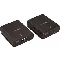
Two black rectangular electronic devices with network ports and indicator lights, no visible text or symbols on the devices themselves.*actual product may vary from photos
For the latest information, technical specifications, and support for this product, please visit www.StarTech.com/ ST12MHDLANU.
FCC Compliance Statement
This equipment has been tested and found to comply with the limits for a Class B digital device, pursuant to part 15 of the FCC Rules. These limits are designed to provide reasonable protection against harmful interference in a residential installation. This equipment generates, uses and can radiate radio frequency energy and, if not installed and used in accordance with the instructions, may cause harmful interference to radio communications. However, there is no guarantee that interference will not occur in a particular installation. If this equipment does cause harmful interference to radio or television reception, which can be determined by turning the equipment off and on, the user is encouraged to try to correct the interference by one or more of the following measures:
• Reorient or relocate the receiving antenna.
- Increase the separation between the equipment and receiver.
- Connect the equipment into an outlet on a circuit different from that to which the receiver is connected.
- Consult the dealer or an experienced radio/TV technician for help
This device complies with part 15 of the FCC Rules. Operation is subject to the following two conditions: (1) This device may not cause harmful interference, and (2) this device must accept any interference received, including interference that may cause undesired operation.
Changes or modifications not expressly approved by StarTech.com could void the user's authority to operate the equipment.
Industry Canada Statement
Use of Trademarks, Registered Trademarks, and other Protected Names and Symbols
This manual may make reference to trademarks, registered trademarks, and other protected names and/or symbols of third-party companies not related in any way to StarTech.com. Where they occur these references are for illustrative purposes only and do not represent an endorsement of a product or service by StarTech.com, or an endorsement of the product(s) to which this manual applies by the third-party company in question. Regardless of any direct acknowledgement elsewhere in the body of this document, StarTech.com hereby acknowledges that all trademarks, registered trademarks, service marks, and other protected names and/or symbols contained in this manual and related documents are the property of their respective holders.
Table of Contents
Introduction......1
Packaging contents....1
System requirements....1
Product diagram ......2
Transmitter Unit....2
Receiver Unit....3
Installation 4
Preparing your site....4
Hardware installation .... 4
Software installation....6
Software operation......6
Connecting your transmitters and receivers to the software 6
Switching your remote displays between video sources....10
Configuring your remote displays for a video wall application 12
Advanced operation and help....16
Technical support....18
Warranty information....18
Introduction
Packaging contents
• 1 x HDMI over IP transmitter
• 1 x HDMI over IP receiver
- 2 x power adapters
- 2 x screws
- 1 x screwdriver
- 2 x Cat5 cables
- 2 x mounting brackets
- 1 x quick install guide
System requirements
- HDMI enabled video source (e.g. acomputer or Blu-ray™ player)
- HDMI enabled display device(s) (e.g. television, projector), one for each receiver
• HDMI cabling for your video source and each display
• Available AC electrical outlet for the transmitter and each receiver
• Network cabling for the extender and each receiver - Standard USB A to USB B cable (optional for USB peripheral extension)
- Up to four USB peripheral devices (optional for USB peripheral extension)
Product diagram
Transmitter Unit

- USB host port
- Video input port (HDMI)
- LAN port (RJ-45 connector)
- Reset button
- Power jack
- Link and power LED
- Function 2 button
- Function 1 button
- Dip rotary switch
- Serial control (not active)
- Serial extension (for extending RS232 signal)
Receiver Unit

- USB peripheral ports
- Video output port (HDMI)
- LAN port (RJ-45 connector)
- Reset button
- Power jack
- Link and power LED
- Function 2 button
- Function 1 button
- Dip rotary switch
- Serial control (not active)
- Serial extension (for extending RS232 signal)
Note: Serial 1 (control) ports are not active. To control the ST12MHDLANU please download our free mobile application. (see Page *.)
(Additional receiver units sold separately, StarTech.com SKU: ST12MHDLANUR)
Installation
Preparing your site
Note: The ST12MHDLANU HDMI extender kit lets you extend your video and USB signals over a Gigabit LAN network – beyond the typical cable length restriction of 330 ft. (100m) of Gigabit network portals.
Refer to the manufacturer of the network equipment to determine the length restriction and to ensure the transmitter unit and receiver unit(s) are all within the restricted range of the nearest network portal.
Ensure the transmitter unit, and receiver unit(s) are all situated near AC electrical outlets.
- Determine where the local video source (i.e. computer, Blu-ray player) will be located and set up the transmitter device near that location.
- Determine where the remote display will be located and set up the receiver near that location.
- (Optional) If using additional displays determine where they will be located and set the additional receiver unit(s) near that location.
Hardware installation
Video wall or point to multi-point installation with a Gigabit LAN network
- Install the transmitter unit
a) Connect a video source device, such as a computer or Blu-ray player, to the transmitter's video input port.
b) (Optional) If you're using the ST12MHDLANU extender kit to extend USB peripheral devices, use a standard USB A to USB B cable to connect the USB host port on the transmitter unit to a USB port on a video source device such as a computer or Blu-ray player.
c) Connect the transmitter's DC 9-12V power jack to an AC electrical outlet, using one of the included power adapters.
- Install the receiver unit(s)
a) Connect a display to the receiver unit's video output port using an HDMI cable.
b) (Optional) If you are using the ST12MHDLANU extender kit to extend USB peripheral devices, connect up to four USB peripheral devices to the receiver unit's USB ports.
c) Connect the receiver unit's power jack to an AC electrical outlet, using one of the included power adapters.
d) (Optional) If you are using additional ST12MHDLANUR receivers (sold separately), repeat steps [a) through c)] for each additional receiver.
Note: The rotary dip switches on the transmitter and each receiver connected to the network must be set in the same position for the devices to communicate.
- Connect the devices to a Gigabit LAN network
a) Connect an RJ-45 terminated Cat5e or Cat6 Ethernet cable to the LAN port on the transmitter unit, and to each of the receiver units.
b) Connect the other end of the Cat5e or Cat6 cable to a Gigabit LAN hub, router or switch.
Note: Your router must support IGMP snooping. Please refer to your network switch or router documentation to ensure IGMP snooping is supported and enabled.
- Verify that the image from your video source appears on video display(s) attached to the receiver unit(s).

flowchart
graph TD
    A["Router"] --> B["Central Device 1"]
    A --> C["Central Device 2"]
    A --> D["Central Device 3"]
    A --> E["Central Device 4"]
    A --> F["Central Device 5"]
    B --> G["Host 1"]
    C --> H["Host 2"]
    D --> I["Host 3"]
    E --> J["Host 4"]
    F --> K["Host 5"]
(Additional receiver units sold separately, StarTech.com SKU: ST12MHDLANUR)
Software installation
The HDMI distribution kit features video control software that helps you manage your IP video distribution and video wall configuration. The software is available on iOS for iPhone or iPad, and Android™ for smartphones or tablets
To install the software:
- Visit http://www.StarTech.com/ST12MHDLANU, using the device you intend to install software on.
- Under the overview tab, select the link for the store that corresponds with your device.


-
Select the option to download and install the software from the store page.
-
Open the software, to verify that it has installed correctly.
Software operation
Connecting your transmitters and receivers to the software
Notes:
- Your router must support IGMP snooping. Please refer to your network switch or router documentation to ensure IGMP snooping is supported and enabled on your router.
- The smartphone or tablet, that you've installed the software on, is connected to the same network as your transmitter(s) and receiver(s)
- Launch the application by clicking the icon on your smartphone or tablet.

natural_image
StarTech.com logo featuring a grid of green and white flowers on a yellow background (no text or symbols on the graphic itself)- The application will open on the Devices tab, and will automatically search for transmitters and receivers on your network and list them within the Devices tab. Note: you can reinitiate the device search, by selecting refresh button in the top

bar
StarTech.com | Device | Value | | :--- | :--- | | 0000 | 192.16.0.212 | | 1000 | 192.16.0.221 | | 1100 | 192.16.0.22 | | Receivers (10) | | | 010 | 192.168.0.3 | | 011 | 192.168.0.4 | | 012 | 192.168.0.5 | | 013 | 192.168.0.6 | | 014 | 192.168.0.7 | | 015 | 192.168.0.8 | | 016 | 192.168.0.9 | | 019 | 192.168.0.233 | | 024 | 192.168.0.2 | | 01C | 192.168.0.232 |right-hand corner of the Devices tab.
- By default, each video device will have an IP address in the range of 169.254.x.x with a subnet mask of 255.255.0.0.
Each transmitter and receiver must have an IP address in the same range, and have an identical subnet mask, as each other, and the tablet or smartphone you have the software installed on.
For example: If your transmitter has an IP address of 169.254.10.10 with a subnet mask of 255.255.0.0.
You must ensure the tablet or smartphone you have the software installed on and each receiver has an IP address that starts with 169.254.x.x (with a varying last two digits represented here by xx) and a subnet mask of 255.255.0.0.
To adjust the IP address and subnet mask of your transmitter(s) and receiver(s):
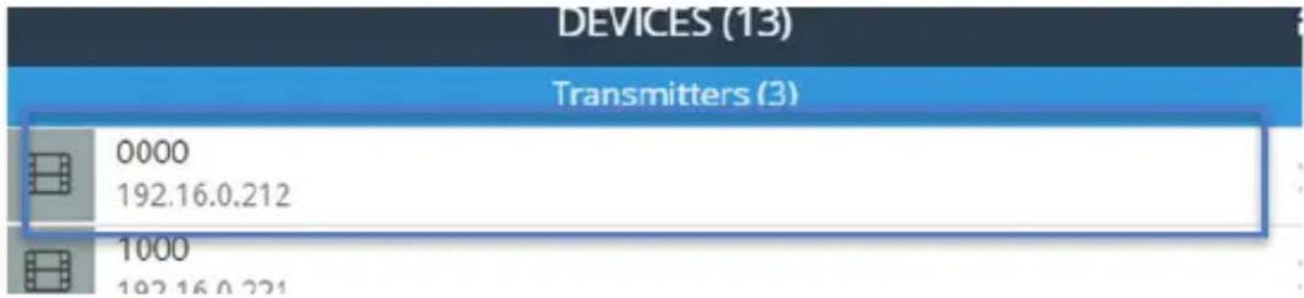
a. Select the transmitter or receiver you'd like to adjust from the Devices tab.
IP:
192.16.0.212

b. Click the edit Icon listed in the IP address section.
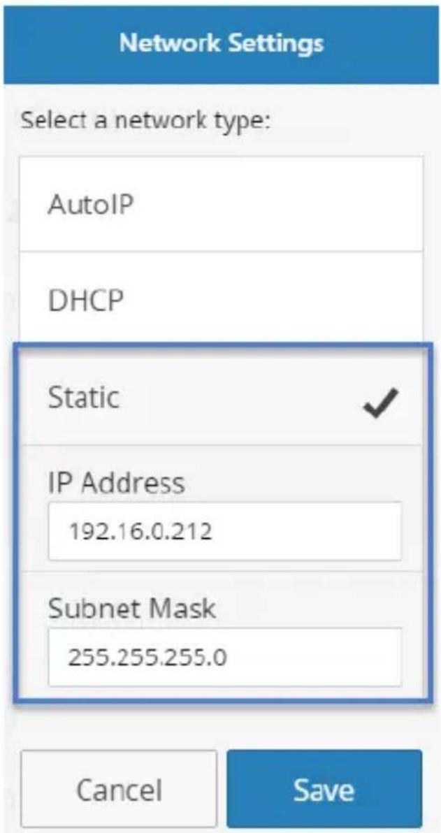
c. Select Static IP and type an IP address and mask for the device.
Or
Select DHCP and your network automatically assign an IP address and mask to for the device in the range of the rest of your network devices.

Note: DHCP must be enabled on your network to automatically assign an IP address and mask in that range.
Switching your remote displays between video sources
- Once the application is launched, select the Switches tab.

- A list of each connected receiver will be displayed with all available transmitters displayed beside them. The transmitter that is currently selected for each receiver will be highlighted in yellow.

Note: if the receiver is part of a video wall it will be indicated with a button that lists the wall configuration and the location of the receiver.
- To assign a video source, or change your video source, select the transmitter listed next to your receiver that you'd like to display.

- The transmitter will turn yellow and your video source will switch on the remote display.
Note: If a receiver that was part of a video wall configuration is altered, that display will no longer be part of the video wall configuration.
Configuring your remote displays for a video wall application
- Once the application is launched, select the Walls tab.

- Select the + icon to launch a wizard that will walk you through your video wall creation.

No walls have been created on this device.
To create a wall, press the + icon above.
- The first page in the wizard enables you to specify the walls name as well as the number of rows and columns you would like to use in your video wall. Each row and column will represent a display in your video wall. Type your preferred name and specify the number of rows and columns, then click next.

Note: a Wall Name will be listed by default, once you type a new name the default name will be overwritten.
- The next page in the wizard will create an example of the video wall with the number of rows and columns you specified.
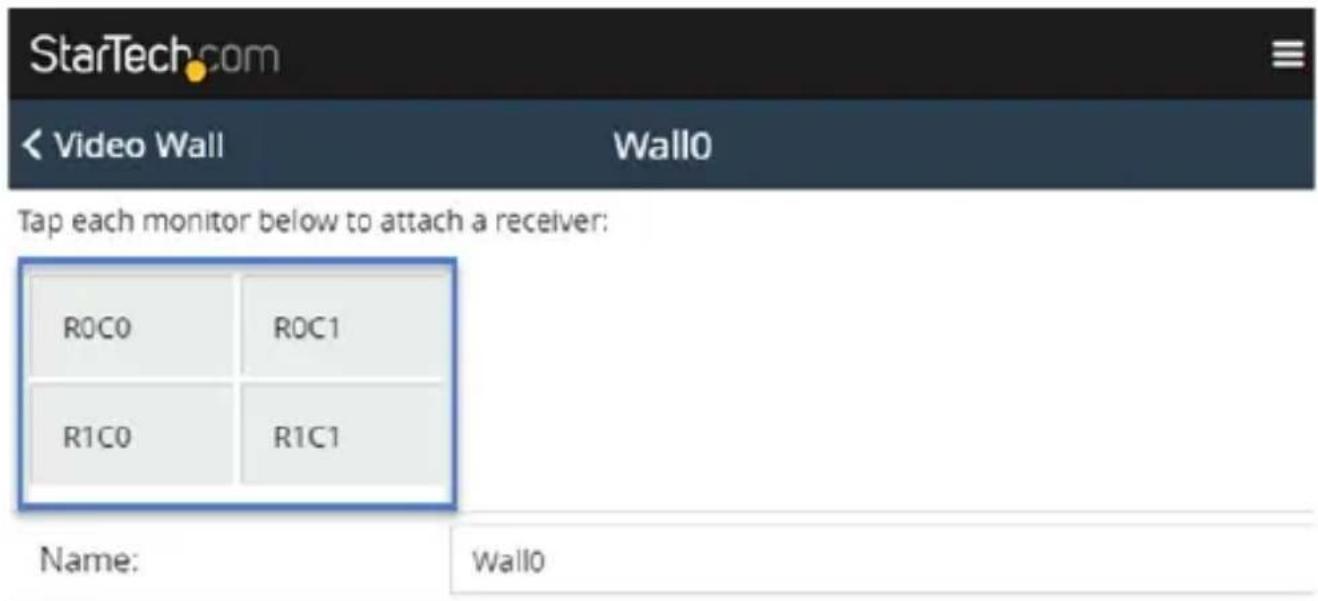
You'll need to use this example to specify which receivers are represented within your video wall configuration. Select the receiver from the video wall example to display a list of all connected receivers, then choose the receiver that corresponds with the proper location within your video wall configuration.

Note: If you'd like to see the receiver device name on each screen, so you can easily identify which display is connected to each receiver, please select the show device names on screen switch. This can be deactivated once you've identified your displays.
Show device names on screen

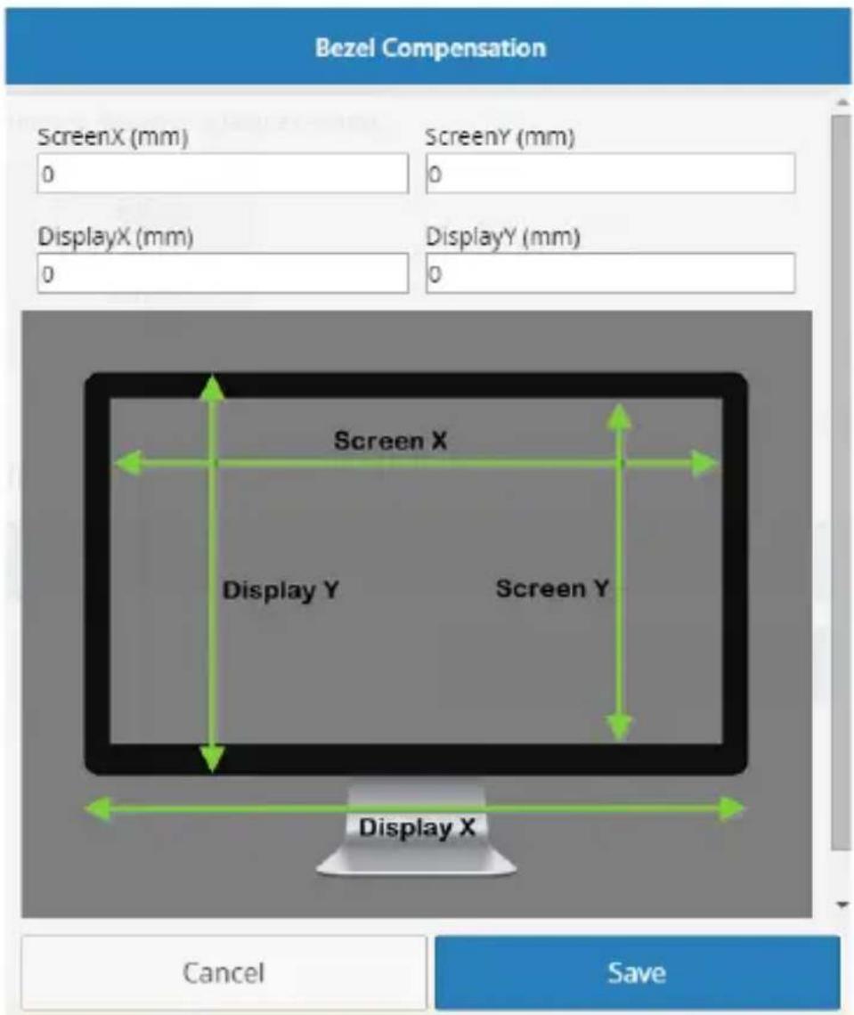
- (Optional) If the displays in your video wall configuration have large bezels or empty space between them, you can scale the image on the displays to create a more natural, seamless look by specifying the bezel compensation. Click the Bezel Compensation button to open the window.
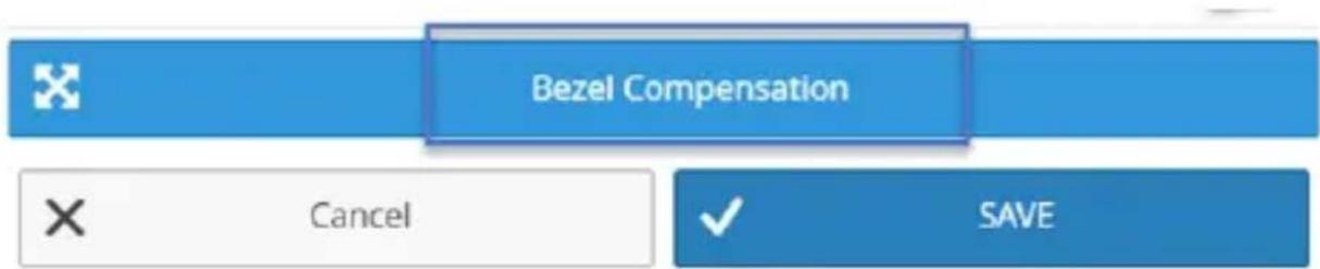
On the bezel compensation window, please enter the following measurements in millimeters (mm): screen width of each display (ScreenX), screen height of each display (ScreenY), total width of each display (DisplayX) and total height of each display (DisplayY). Then click the Save button.
- The wizard is now complete and your created video wall configuration will appear on the Walls tab.
You can select or switch your video source for each created video wall configuration clicking transmitters listed below each created video wall configuration.

Notes:
- The display indicators will show the status of the current wall. Blue indicates that the display is active, Grey indicates it is being used for another wall or switch.
- You can adjust the settings defined for each video wall configuration or delete your video wall configuration by clicking the arrow next to each video wall.

Advanced operation and help
You can access the software menu from any screen by clicking the menu icon in the top right-hand corner of the application.

From the menu you can access the below each of the below options. A description for each option and listed below:
| Menu | |
| ? Help | |
| Device Search Mode: | Multicast DNS |
| Clear All Settings | |
| Demo Mode | |
Help:
Lists information and walk-throughs regarding operation of the application.
Device Search Mode:
Enables you to define your preferred method of transmitter and receiver identification over your network that the software uses. You can choose between two methods of identification: Multicast DNS or Target IP for your transmitters and receivers.
Multicast DNS: is the default setting and will search automatically for devices over the network.
Target IP: is an advanced setting that enables you to specify an IP address that the remote devices are set to in order for the software to identify them. This is a good option if you'd like multiple set ups with different displays and transmitters on different subnets and IP address ranges.
Clear All Settings:
Restores your software to default settings.
Demo Mode:
Creates a virtual environment with multiple transmitters and receivers that enables you to configure a virtual setup without connected transmitters and receivers to test the functionality of the software.
Technical support
StarTech.com's lifetime technical support is an integral part of our commitment to provide industry-leading solutions. If you ever need help with your product, visit www.startech.com/support and access our comprehensive selection of online tools, documentation, and downloads.
For the latest drivers/software, please visit www.startech.com/downloads
Warranty information
This product is backed by a two-year warranty.
StarTech.com warrants its products against defects in materials and workmanship for the periods noted, following the initial date of purchase. During this period, the products may be returned for repair, or replacement with equivalent products at our discretion. The warranty covers parts and labor costs only. StarTech.com does not warrant its products from defects or damages arising from misuse, abuse, alteration, or normal wear and tear.
Limitation of liability
In no event shall the liability of StarTech.com Ltd. and StarTech.com USA LLP (or their officers, directors, employees or agents) for any damages (whether direct or indirect, special, punitive, incidental, consequential, or otherwise), loss of profits, loss of business, or any pecuniary loss, arising out of or related to the use of the product exceed the actual price paid for the product. Some states do not allow the exclusion or limitation of incidental or consequential damages. If such laws apply, the limitations or exclusions contained in this statement may not apply to you.

Instruction manual
Hard-to-find made easy. At StarTech.com, that isn't a slogan. It's a promise.
StarTech.com is your one-stop source for every connectivity part you need. From the latest technology to legacy products — and all the parts that bridge the old and new — we can help you find the parts that connect your solutions.
We make it easy to locate the parts, and we quickly deliver them wherever they need to go. Just talk to one of our tech advisors or visit our website. You'll be connected to the products you need in no time.
Visit www.startech.com for complete information on all StarTech.com products and to access exclusive resources and time-saving tools.
StarTech.com is an ISO 9001 Registered manufacturer of connectivity and technology parts. StarTech.com was founded in 1985 and has operations in the United States, Canada, the United Kingdom and Taiwan servicing a worldwide market.




- HDMI over IP Extender Kit with USB and Serial
- FCC Compliance Statement
- Industry Canada Statement
- Use of Trademarks, Registered Trademarks, and other Protected Names and Symbols
- Table of Contents
- Introduction......1
- Product diagram ......2
- Installation 4
- Software operation......6
- Technical support....18
- Warranty information....18
- Introduction
- Packaging contents
- System requirements
- Product diagram
- Transmitter Unit
- Receiver Unit
- Installation
- Preparing your site
- Hardware installation
- Software installation
- Software operation
- Connecting your transmitters and receivers to the software
- Notes:
- To adjust the IP address and subnet mask of your transmitter(s) and receiver(s):
- Switching your remote displays between video sources
- Configuring your remote displays for a video wall application
- Advanced operation and help
- Help:
- Device Search Mode:
- Clear All Settings:
- Demo Mode:
- Technical support
- Warranty information
- Limitation of liability
Brand : StarTech.com
Model : ST12MHDLANU
Category : Audio/video extension