
802VLZ4 - Mixer MACKIE - Free user manual and instructions
Find the device manual for free 802VLZ4 MACKIE in PDF.


| Product Type | Compact Analog Mixer |
| Brand | Mackie |
| Model | 802VLZ4 |
| Number of Channels | 8 (4 mono + 2 stereo) |
| Mono Input Channels | 4 with VLZ preamps (XLR/TRS combo) |
| Stereo Input Channels | 2 (RCA and 1/4" TRS) |
| EQ per Channel | 3-band (Hi, Mid, Low) on mono channels |
| Aux Sends | 2 (Pre/Post switchable) |
| Main Outputs | XLR and 1/4" TRS (balanced) |
| Control Room Output | 1/4" TRS |
| Headphone Output | 1/4" TRS with level control |
| Phantom Power | +48V (global switch) |
| Dimensions (Width x Depth x Height) | 8.9 x 10.6 x 3.5 in (226 x 269 x 89 mm) |
| Weight | 4.1 lb (1.86 kg) |
| Power Supply | External 12V DC, 1A (included) |
| Frequency Response | 20 Hz - 20 kHz (+0/-1 dB) |
| Total Harmonic Distortion | <0.005% (20 Hz - 20 kHz) |
| Signal-to-Noise Ratio | >110 dB (A-weighted) |
| Construction Material | Steel chassis, polycarbonate knobs |
| Maintenance | Clean with dry, lint-free cloth; avoid liquids |
| Safety | Keep away from moisture; use only supplied power supply |
| Spare Parts & Reparability | Contact Mackie support or authorized service centers |
Frequently Asked Questions - 802VLZ4 MACKIE
User questions about 802VLZ4 MACKIE
0 question about this device. Answer the ones you know or ask your own.
Ask a new question about this device
Download the instructions for your Mixer in PDF format for free! Find your manual 802VLZ4 - MACKIE and take your electronic device back in hand. On this page are published all the documents necessary for the use of your device. 802VLZ4 by MACKIE.
USER MANUAL 802VLZ4 MACKIE
8-Channel Ultra-Compact Mixer
OWNER'S MANUAL

Important Safety Instructions
- Read these instructions.
- Keep these instructions.
- Heed all warnings.
- Follow all instructions.
- Do not use this apparatus near water.
- Clean only with a dry cloth.
- Do not block any ventilation openings. Install in accordance with the manufacturer's instructions.
- Do not install near any heat sources such as radiators, heat registers, stoves, or other apparatus (including amplifiers) that produce heat.
- Do not defeat the safety purpose of the polarized or grounding-type plug. A polarized plug has two blades with one wider than the other. A grounding-type plug has two blades and a third grounding prong. The wide blade or the third prong are provided for your safety. If the provided plug does not fit into your outlet, consult an electrician for replacement of the obsolete outlet.
- Protect the power cord from being walked on or pinched particularly at plugs, convenience receptacles, and the point where they exit from the apparatus.
-
Only use attachments/accessories specified by the manufacturer.
-
Use only with a cart, stand, tripod, bracket, or table specified by the manufacturer, or sold with the apparatus. When a cart is used, use caution when moving the cart/apparatus combination to avoid injury from tip-over.
-
Unplug this apparatus during lightning storms or when unused for long periods of time.
-
Refer all servicing to qualified service personnel. Servicing is required when the apparatus has been damaged in any way, such as power-supply cord or plug is damaged, liquid has been spilled or objects have fallen into the apparatus, the apparatus has been exposed to rain or moisture, does not operate normally, or has been dropped.
-
This apparatus shall not be exposed to dripping or splashing, and no object filled with liquids, such as vases or beer glasses, shall be placed on the apparatus.
-
Do not overload wall outlets and extension cords as this can result in a risk of fire or electric shock.
-
The MAINS plug or an appliance coupler is used as the disconnect device, so the disconnect device shall remain readily operable.
| CAUTION AVISRISK OF ELECTRIC SHOCK. DO NOT OPENRISQUE DE CHOC ELECTRIQUE. NE PAS OUVRIR |
| CAUTION TO REDUCE THE RISK OF ELECTRIC SHOCK DO NOT REMOVE COVER (OR BACK)NO USER-SERVICEABLE PARTS INSIDE. REFER SERVICING TO QUALIFIED PERSONNELATTENTION: POUR EVITER LES RISQUES DE CHOC ELECTRIQUE, NE PAS ENLEVER LE COUVERCLE.AUCOUN ENTRETIEN DE PIECES MITERIEURES PAR L'USAGERCONPIER L'ENTRETIEN AU PERSONNEL QUALIFEAVIS. POUR EVITER LES RISQUES D'INCENDIE OU D'ELECTROCUTION, INXPOSEZ PAS CET ARTICLEA LA PLUIE OU A L'HUMIDITE |
- NOTE: This equipment has been tested and found to comply with the limits for a Class B digital device, pursuant to part 15 of the FCC Rules. These limits are designed to provide reasonable protection against harmful interference in a residential installation. This equipment generates, uses, and can radiate radio frequency energy and, if not installed and used in accordance with the instructions, may cause harmful interference to radio communications. However, there is no guarantee that interference will not occur in a particular installation. If this equipment does cause harmful interference to radio or television reception, which can be determined by turning the equipment off and on, the user is encouraged to try to correct the interference by one or more of the following measures:
• Reorient or relocate the receiving antenna.
- Increase the separation between the equipment and the receiver.
- Connect the equipment into an outlet on a circuit different from that to which the receiver is connected.
- Consult the dealer or an experienced radio/TV technician for help.
CAUTION: Changes or modifications to this device not expressly approved by LOUD Technologies Inc. could void the user's authority to operate the equipment under FCC rules.
- This apparatus does not exceed the Class A/Class B (whichever is applicable) limits for radio noise emissions from digital apparatus as set out in the radio interference regulations of the Canadian Department of Communications.
- Exposure to extremely high noise levels may cause permanent hearing loss. Individuals vary considerably in susceptibility to noise-induced hearing loss, but nearly everyone will lose some hearing if exposed to sufficiently intense noise for a period of time. The U.S. Government's Occupational Safety and Health Administration (OSHA) has specified the permissible noise level exposures shown in the following chart.
According to OSHA, any exposure in excess of these permissible limits could result in some hearing loss. To ensure against potentially dangerous exposure to high sound pressure levels, it is recommended that all persons exposed to equipment capable of producing high sound pressure levels use hearing protectors while the equipment is in operation. Ear plugs or protectors in the ear canals or over the ears must be worn when operating the equipment in order to prevent permanent hearing loss if exposure is in excess of the limits set forth here:
| Duration, per day in hours | Sound Level dBA, Slow Response | Typical Example |
| 8 | 90 | Duo in small club |
| 6 | 92 | |
| 4 | 95 | Subway Train |
| 3 | 97 | |
| 2 | 100 | Very loud classical music |
| 1.5 | 102 | |
| 1 | 105 | Matt screaming at Troy about deadlines |
| 0.5 | 110 | |
| 0.25 or less | 115 | Loudest parts at a rock concert |
Contents
IMPORTANT SAFETY INSTRUCTIONS ...... 2
CONTENTS....3
FEATURES 4
INTRODUCTION 4
HOW TO USE THIS MANUAL......4
GETTING STARTED......5
THINGS TO REMEMBER 5
HOOKUP DIAGRAMS......6
PATCHBAY DESCRIPTION....11
- MIC INS (CHANNELS 1–3) ...... 11
- LINE INS (CHANNELS 1–2)......12
- STEREO LINE INS......12
- CHANNEL INSERT (CHANNELS 1–2)......12
- LOW CUT (CHANNELS 1–3)......13
- INSTRUMENT SWITCH (CHANNELS 1–2)..13
- GAIN (CHANNELS 1–3) ......13
- STEREO RETURN 13
- ALT 3-4 OUTS....13
- CONTROL ROOM OUTS......14
- PHONES 14
- PHANTOM SWITCH AND LED 14
- TAPE IN 14
- TAPE OUT 15
- AUX SEND 15
- 1/4" MAIN OUTS....15
- XLR MAIN OUTS 15
- XLR MAIN OUT LEVEL SWITCH......15
- POWER CONNECTION......15
- POWER SWITCH....15
CHANNEL STRIP DESCRIPTION....16
- LEVEL 16
- PRE FADER SOLO 16
- MUTE/ALT 3-4....16
- PAN....17
- LOW EQ....17
- MID EQ....17
- HI EQ....17
- AUX 18
OUTPUT SECTION....19
- MAIN MIX 19
- CONTROL ROOM SOURCE MATRIX......19
- PHONES 19
- CONTROL ROOM/SUBMIX 19
- ASSIGN TO MAIN MIX......20
- RUDE SOLO....20
- METERS 20
- PRE OR POST (AUX) 21
- AUX MASTER SEND 21
- STEREO RETURN 21
- POWER LED 21
APPENDIX A: SERVICE INFORMATION......22
APPENDIX B: CONNECTIONS.... 22
APPENDIX C: TECHNICAL INFORMATION...... 25
802VLZ4 LIMITED WARRANTY 27
Please write your serial number here for future reference (i.e., insurance claims, tech support, return authorization, make dad proud, etc.)
Purchased at:
Date of purchase:

Like us

Follow us

Watch our dang videos
Features
- 8-channel mixer featuring our signature high-headroom, low-noise design
• 3 boutique-quality Onyx mic preamps
• Ultra-wide 60 dB gain range
• 128.5 dB dynamic range
• +22 dBu line input handling
• Extended frequency response
• Distortion under 0.0007% [20 Hz – 50 kHz]
- Improved RF rejection, perfect for broadcast applications
• Phantom power for condenser mics
• 8 high-headroom line inputs - Selectable instrument inputs on first two channels – no DI box needed
• 3-band EQ (80 Hz, 2.5 kHz, 12 kHz)
• 18 dB/oct 100 Hz low-cut filter on mic input channels - Aux send, level, pan and PFL solo on each channel
- Stereo return for connecting FX processor or other stereo source
• ALT 3/4 stereo bus for added routing flexibility
• Control room / phones source matrix
• High-resolution 12-segment stereo meters
• Sealed rotary controls resist dust and grime - “Built-Like-A-Tank” rugged steel chassis with powder-coat finish
- High-visibility, high-contrast controls deliver convenient "at-a-glance" visual feedback
• Universal power supply for worldwide use
Introduction
The 8-channel 802VLZ4 features the proven performance of our flagship Onyx mic preamps in a desk-friendly, ultra-compact design, perfect for professional applications with a lower input need.
From every input to every output, the 802VLZ4 is designed to provide the highest headroom and lowest noise possible for maximum signal integrity.
Plus, it truly is “Built-Like-A-Tank” with a ridiculously rugged solid steel chassis and high-contrast controls for ultimate tactile control.
And with features like instrument level inputs, phantom power and level metering, the 802VLZ4 offers a true step-up performance and durability that's ideal for your professional application.
How To Use This Manual
After this introduction, a getting started guide will help you get things set up fast. The hookup diagrams show some typical setups, while the remaining sections provide details of the 802VLZ4 mixer.

This icon marks information that is critically important or unique to the 802VLZ4. For your own good, read and remember them.

This icon will lead you to in-depth explanations of features and some practical tips. They usually have some valuable nuggets of information.

This icon draws attention to certain features and functions relating to the usage of the 802VLZ4.
Need help with your mixer?
- Visit www.720trees.com and click 'Contact Tech Support' to find: FAQs, manuals, addendums, and other documents.
- Email us at: techmail@loudtechinc.com.
- Telephone 1-800-898-3211 to speak with one of our splendid technical support representatives (Monday-Friday, during normal business hours, Pacific Time).
Getting Started
The following steps will help you set up the 802VLZ4 mixer quickly.
- Make all initial connections with the power switches OFF on all equipment. Make sure the gain knobs and main mix knob are fully down [counter-clockwise].
- Set the level knobs and EQ knobs at the center [unity].
- Connect the signal source to the input of channel 1.
- Connect the main outputs of the 802VLZ4 to the inputs of powered speakers [or to the inputs of an amplifier which should be connected to passive speakers].
- Push the 3-pin female side of the power adaptor securely into the connector on the rear of the 802VLZ4. Plug the other end into an AC outlet properly configured with the correct voltage as indicated on the AC adaptor.
- Light some incense, man...
- Turn the mixer on.
- Turn the speakers on.
- Start the signal source and raise the main mix knob up until audio may be heard through the speakers.
- Adjust the gain control so that the meter display stays around "0" [Level Set] and never goes higher than "+6".
- If you'd like to apply some EQ, do so now and repeat step 9.
- Repeat for the remaining channels, if required.
Things to Remember
- Never listen to loud music for prolonged periods. Please see the Safety Instructions on page 3 for information on hearing protection.
- As a general guide, the 802VLZ4 should be turned on first, then the speakers. As such, the mixer should also be turned off last.
This will reduce the possibility of any turn-on or turn-off thumps and other noises generated by any upstream equipment from coming out of the speakers. - Save the shipping boxes and packing materials! You may need them someday. Besides, the cats will love playing in them and jumping out at you unexpectedly. Remember to pretend that you are surprised!
- Save your sales receipt in a safe place.
Hookup Diagrams
flowchart
graph TD
    A["Electric Guitar"] --> B["Amplifier modeler"]
    B --> C["DI Box"]
    C --> D["802 V1364"]
    D --> E["Effects Processor (connected to aux send)"]
    E --> F["Returns"]
    F --> G["Switch"]
    G --> H["Microphone"]
    G --> I["Aquoustic Guitar"]
    G --> J["Bass Guitar"]
    G --> K["Di Box"]
    K --> L["802 V1364"]
    L --> M["Switch"]
    M --> N["Control knobs"]
    M --> O["Loaders"]
    M --> P["Feedback to DACs"]
    M --> Q["Return"]
    Q --> R["Vocal Compressor (connected to Insert)"]
    R --> S["Send"]
    S --> T["Return"]
    T --> U["Compressor (connected to Insert)"]
    U --> V["Send"]
    V --> W["Return"]
    W --> X["Keyboards"]
    W --> Y["iPod™ Docking Station"]
    Y --> Z["SRM650 Powered Speakers"]
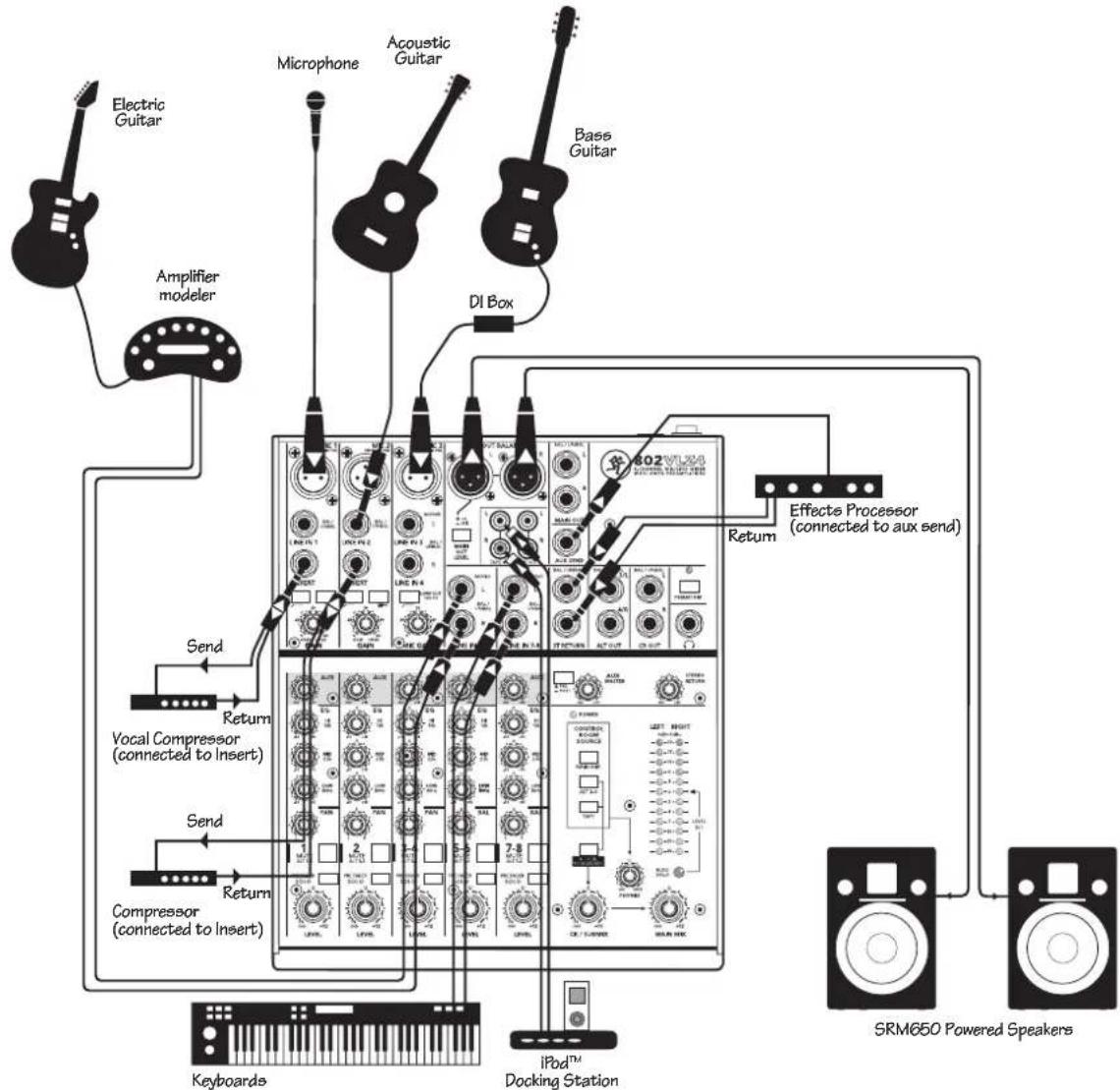
This diagram shows a microphone connected to the mic input of channel 1, and a vocal compressor connected to the insert jack. A guitar is attached to the instrument input of channel 2, with the instrument switch pressed in, and a compressor on the insert. A bass guitar is connected to channel 3's mic input via a DI box, and another guitar plays through an amplifier modeler into channels 5 and 6. Keyboards are connected to the line inputs of channels 7 and 8.
An effects processor is connected to the aux send, with the aux send set to post-level. Effects are added to the main mix via the stereo return inputs, and adjusted with the stereo return level control.
To use the aux send for stage monitors instead of an effects processor, set the aux to pre-level so the monitor volume level can be adjusted independently from the main loudspeakers.
An iPod™ docking station is connected to the tape RCA inputs, so you can play pre-recorded music during the breaks.
The main mix output connects to a pair of SRM650 powered loudspeakers to please your audience.
Live Band PA System

This diagram shows a condenser microphone connected to the mic input of channel 1, with phantom power engaged. A guitar is attached to the instrument input of channel 2, with the instrument switch pressed in. Another guitar plays through an amplifier modeler into channels 3 and 4. A stereo synth is connected to the line inputs of channels 5 and 6, and an electronic drum kit feeds channels 7 and 8.
The audio outputs from a laptop computer are connected to the RCA tape inputs. This allows you to playback your recordings made using the DAW of your choice. The Alt 3-4 outputs are used to feed the inputs to your computer's sound card. By pressing a mute/alt 3-4 switch, it is easy to set up a channel to record onto your computer.
A headphone amplifier is connected to the headphones output, and feeds four pairs of headphones.
A pair of MR8mk3 powered studio monitors are connected to the control room outputs.
You can use this setup to record overdub style:
- For the track being recorded, route it to the alt 3-4 output, which feeds the computer input.
- Monitor just the previously-recorded tracks through the tape input, which will feed the control room/phones.
- Since only the currently-recorded track is feeding the computer (through alt 3-4), you will hear the previous tracks you are overdubbing to, but they will not be recorded to each new track.
- The control room/phones is fed by a mixture of alt 3-4 (currently recorded track) and tape in (output of your DAW playing back previously-recorded tracks).
Home Studio
flowchart
graph TD
    A["Stage monitor mix from FOH mixer"] --> B["802V1.24"]
    B --> C["Main mix to FOH mixer"]
    C --> D["Headphones"]
    D --> E["Stage Snake"]
    E --> F["Keyboard submix to front-of-house mixer"]
    G["SRM150 powered personal monitor"] --> H["Mono synth 1"]
    H --> I["Mono synth 2"]
    I --> J["Synth 3"]
    J --> K["Synth 4"]
    K --> L["Stage Snake"]
    style A fill:#f9f,stroke:#333
    style B fill:#ccf,stroke:#333
    style C fill:#cfc,stroke:#333
    style D fill:#fcc,stroke:#333
    style E fill:#cff,stroke:#333
    style F fill:#ffc,stroke:#333
    style G fill:#f9f,stroke:#333
    style H fill:#ccf,stroke:#333
    style I fill:#cfc,stroke:#333
    style J fill:#f9f,stroke:#333
    style K fill:#ccf,stroke:#333
    style L fill:#ffc,stroke:#333
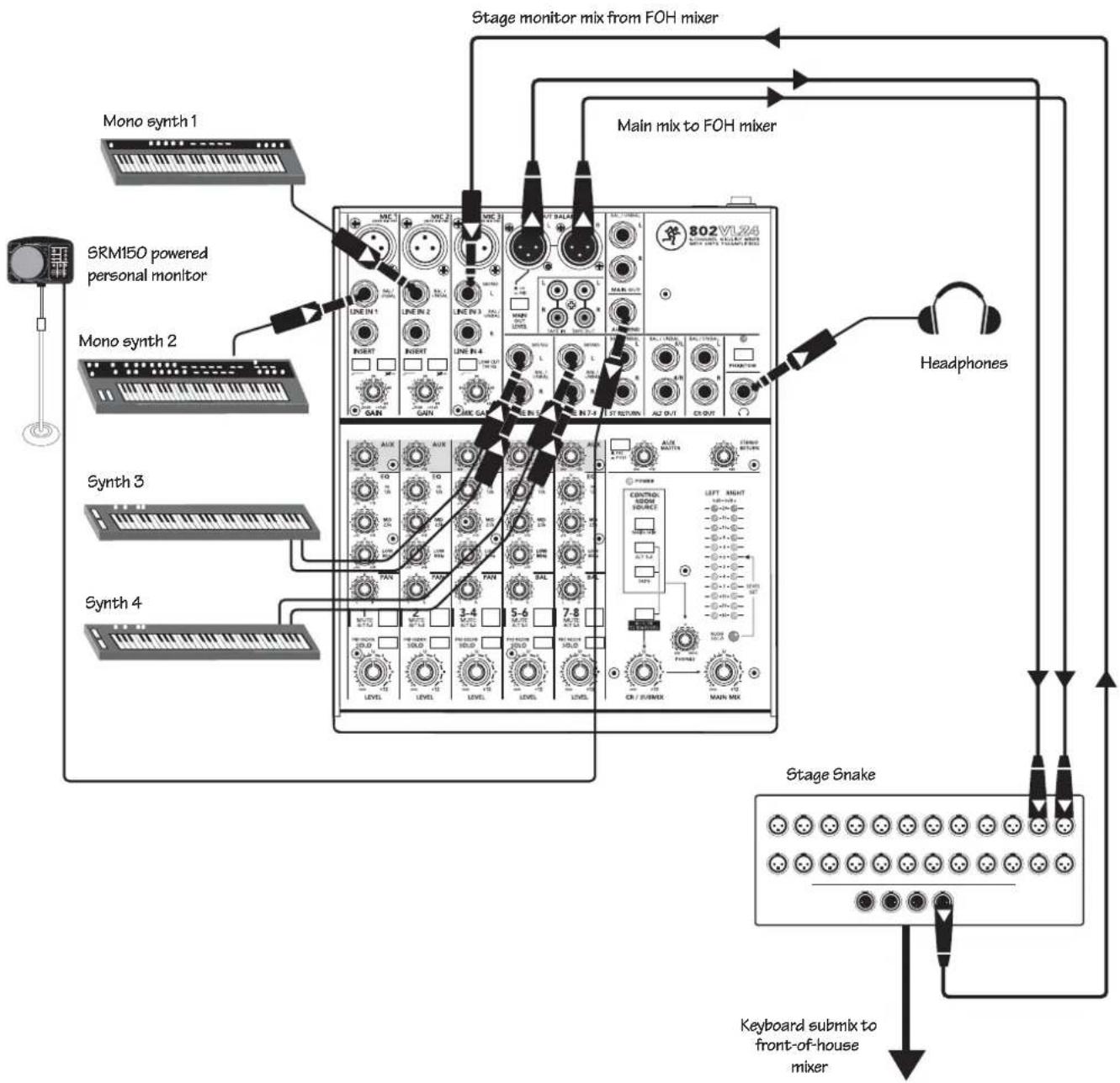
This diagram shows mono synths connected to the mono line inputs of channel 1 and 2, and stereo synths connected to the stereo line inputs of channels 5/6, and 7/8.
The XLR main mix outputs are connected to two channels of a stage snake. The main output level switch next to the main outputs is set to mic, and these balanced outputs are then suitable for sending over long cable runs from the snake to the front of house mixer. Here, the keyboard submix is added to main mix with the other instruments and vocals of your legendary all-star band.
The snake returns a stage monitor feed from the FOH mixer into channel 3's line input. Leave the channel 3 level down, so this feed is not sent to the main mix of the 802VLZ4. Adjust the channel 3 aux control to add the stage monitor mix from the front of house mixer. Adjust the other channel's aux controls until you are happy with the overall monitor mix of your keyboards and the band's guitars/ drums/vocals etc. Set the aux post/pre switch to pre-level to run the SRM150 as a powered stage monitor. With this arrangement, you have more control over what you hear in the monitor. You can add "more me" and "less them," and generally adjust the monitor mix to your liking.
A pair of headphone is connected to the headphones output.
Keyboard Submixer

This diagram shows two voice-over microphones connected to the mic inputs of channels 1 and 2. The stereo line-level outputs from two digital video players connect to the line inputs of channels 3/4, and 5/6.
A stereo sound effects hard disk player is connected to the line inputs of channels 7 and 8.
The tape outputs connect to the line-level audio inputs of a desktop computer running your favorite DAW. You will probably need a dual RCA to 1/8" adapter, or cable to connect to your computer's audio input.
The control room outputs feed a pair of MR8mk3 powered studio monitors. The main mix outputs are feeding the balanced audio inputs of a video recorder.
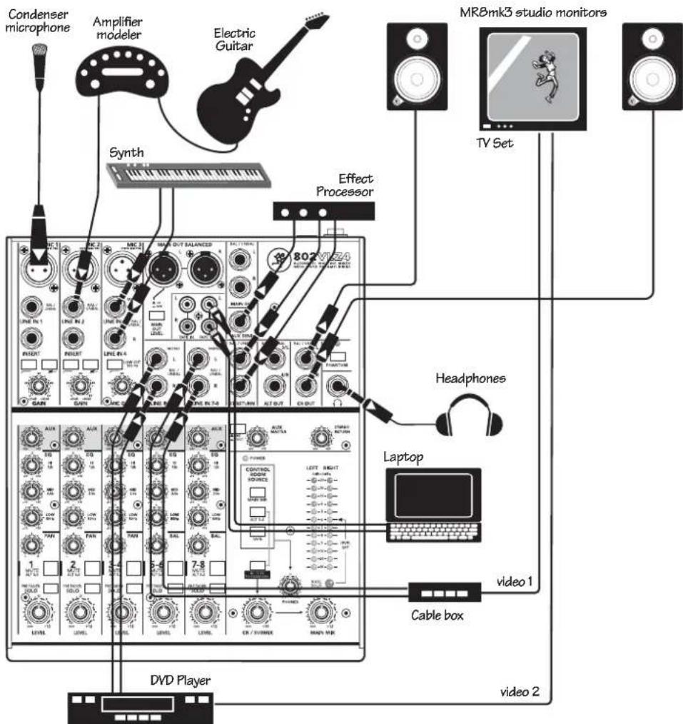
This system is useful if you are short on space, or you are in love with a really nice pair of loudspeakers and want to share them in a home theater and home studio.
A condenser microphone is connected to the mic input of channel 1, with phantom power engaged. The line-level output from a guitar amplifier modeler feeds the line input of channel 2. A stereo synth is connected to channels 3 and 4. A laptop computer running the DAW of your choice is connected to the tape output, so you can record channels 1, 2, 3, and 4.
The stereo line-level audio output from a DVD player is connected to channels 5 and 6, and a cable box's audio output is connected to channels 7 and 8. The video output from the cable box and DVD player connect directly to the TV monitor.
An external effects processor is connected to the aux send (in post mode) and its output connects to the 802VLZ4 stereo return inputs.
A pair of MR8mk3 powered studio monitors is connected to the control room outputs. A pair of headphones is connected to the headphones output.
To use the home studio, sing and play your guitar, and record using the DAW of your choice, or listen through the nice speakers and headphones. Turn down channel 5/6 and 7/8 levels if you are not using the home theater.
To use the home theater, turn down channel 1-4's level knobs. Select a program using the cable box, and set the channel 7-8 level knob to unity. Use the control room knob to adjust the level in your loudspeakers. If you play a DVD, turn up the channel 5/6 level control to unity. Use the TV to select which video source you want to see.
Combined Home Studio and Home Theater
Patchbay Description

This is where you plug everything in: microphones, line-level instruments and effects, headphones, and the ultimate destination for your sound: a recorder, PA system, etc.
Appendix B has details and drawings of the connectors you can use with the 802VLZ4. Also see the channel strip description on page 16 for details of the signal routing from the XLR and line inputs.
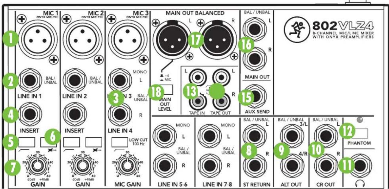
1. Mic Ins (Channels 1–3)
Phantom-powered, balanced Onyx mic preamps are on every VLZ4 mixer. These circuits are excellent at rejecting hum and noise. You can plug in almost any kind of mic that has a standard XLR male mic connector.
Professional ribbon, dynamic, and condenser mics will all sound excellent through these inputs. The 802VLZ4's mic inputs will handle any kind of mic level you can toss at them, without overloading. Be sure to perform the getting started procedure on page 5.
Channel 3-4 is a hybrid design, with a mono mic input in a stereo channel. The mono mic input is fed to both sides of the stereo field.

Not every instrument is made to connect directly to a mixer. Guitars commonly need a Direct Injection (DI) box to connect to
the mixer's mic inputs. Channels 1 and 2 have an instrument switch [6] so you do not need a DI box, and can plug your guitar directly into the line inputs [2].
Phantom Power
Most modern professional condenser mics are equipped for phantom power, which lets the mixer send low-current DC voltage to the mic's electronics through the same wires that carry audio. (Semi-pro condenser mics often have batteries to accomplish the same thing.) "Phantom" owes its name to an ability to be "unseen" by dynamic mics (Shure SM57/SM58, for instance), which don't need external power and aren't affected by it anyway.
The 802VLZ4's phantom power is globally controlled by the phantom power [12] switch. (This means the phantom power for the mic inputs of channels 1-3 is turned on and off together.)

Never plug single-ended (unbalanced) micro phones or instruments into the mic [1] input jacks if the phantom power is on.

Do not plug instrument outputs into the mic input jacks with phantom power on, unless you know for certain it is safe to do so.

Do not use phantom power with ribbon microphones.

2. Line Ins (Channels 1–2)
These inputs share circuitry (but not phantom power) with the mic preamps, and can be driven by balanced or unbalanced sources at almost any level. You can use these inputs for virtually any signal you'll come across, from instrument levels as low as -40 dB to operating levels of -10 dBV to +4 dBu, since there is more gain available than on line inputs 3–8.
To connect balanced lines to these inputs, use a 1/4" Tip-Ring-Sleeve (TRS) plug, the type found on stereo headphones.
To connect unbalanced lines to these inputs, use a 1/4" mono (TS) phone plug or standard instrument cable.
The line inputs 1–2 are a good place to connect older instruments that need more gain. You can correct weak levels by adjusting the corresponding channel's gain control [7].
3. Stereo Line Ins (Channels 3–4, 5–6, and 7–8)
These fully-balanced inputs are designed for stereo or mono, balanced or unbalanced signals. They can be used with just about any professional or semi-pro instrument, effect or CD player.
In the stereo audio world, an odd-numbered channel usually receives the "left signal." For example, you would feed the 802VLZ4's line inputs 5-6 a stereo signal by inserting the device's left output plug into the channel 5 jack, and its right output plug into the channel 6 jack.
When connecting a mono device (just one cord), always use the left (mono) input (jacks 3, 5, or 7) and plug nothing into the right input (jacks 4, 6, or 8)—this way the signal will appear on both sides. This trick is called “jack normalling.”
4. Channel Insert (Channels 1–2)
These jacks are where you connect serial effects such as compressors, equalizers, de-essers, or filters. Since most people don't have more than a few of these gadgets, we've included inserts for just the first two channels. If you want to use this kind of processing on channels 3 through 8, simply patch your source through your processor before you plug into the 802VLZ4.
The channel insert points are after the gain [7] and low cut [5] controls, but before the channel's EQ [25-27] and level [21] controls. The send (tip) is low-impedance (120 ohms), capable of driving any line-level device. The return (ring) is high-impedance (over 2.5 k ohms) and can be driven by almost any device.

flowchart
graph LR
    A["Input"] --> B["TRS plug"]
    B --> C["This plug connects to one of the mixer's Channel Insert jacks."]
    C --> D["SEND to processor"]
    C --> E["RETURN from processor"]
    D --> F["Output"]
    E --> G["Output"]
See Appendix B for details and drawings about insert cables, and a diagram showing three ways to use the jacks.
Besides being used for inserting external devices, these jacks can also be used as channel direct outputs; post-gain, post-low cut, and pre EQ. In fact, our Onyx mic preamps have become so famous, that people buy the mixers just to have some of these preamps in their arsenal.
5. Low Cut (Channels 1–3)
Each low-cut switch, often referred to as a high-pass filter (all depends on how you look at it), cuts bass frequencies below 100 Hz at a rate of 18 dB per octave.
We recommend that you use low-cut on every microphone application except kick drum, bass guitar, or bassy synth patches. These aside, there isn't much down there that you want to hear, and filtering it out makes the low stuff you do want much more crisp and tasty. Not only that, but low-cut can help reduce the possibility of feedback in live situations, and it helps to conserve amplifier power.
Another way to consider low-cut's function is that it actually adds flexibility during live performances. With the addition of low-cut, you can safely use low equalization on vocals. Many times, bass shelving EQ can really benefit voices. Trouble is, adding low EQ also boosts stage rumble, mic handling clunks and breath pops. Applying low-cut removes all those problems, so you can add low EQ without losing a woofer.
6. Instrument Switch (Channels 1–2)
Press these in if you want to connect a guitar or other instrument-level source directly to the line inputs of channels 1 and 2. You will not need a DI box, and your guitar will perform flawlessly (well, as long as your playing is that way).
7. Gain (Channels 1–3)

If you haven't already, please read the getting started section on page 5.
The gain knobs for channels 1 and 2 adjust the input sensitivity of the mic and line inputs. This allows signals from the outside world to be adjusted
to optimal internal operating levels. The gain control for channel 3 just affects the channel 3 mic input only.
If the signal originates through the XLR jack, there will be 0 dB of gain with the knob fully down, ramping to 60 dB of gain fully up.
Through the 1/4" input (ch 1 and 2 only), there is 20 dB of attenuation fully down and 40 dB of gain fully up, with a "U" (unity gain) mark at 10:00. This 20 dB of attenuation can be very handy when you are inserting a very hot signal, or when you want to add a lot of EQ gain, or both. Without this "virtual pad," this scenario might lead to channel clipping.
Effects: Serial or Parallel?
The next sections toss the terms "serial" and "parallel" around like hacky sacks. Here's what we mean by them:
“Serial” means that the entire signal is routed through the effects device. Examples: compressor/limiters, graphic equalizers. Line-level sources may be patched through a serial effects device before or after the mixer, or preferably through the insert jacks [4].

flowchart
graph LR
    A["Dry Signal"] -->|Insert Send| B["Signal Processor (e.g., Compressor)"]
    B -->|Insert Return| C["Processed Signal"]
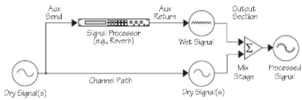
“Parallel” means that a portion of the signal in the mixer is tapped off to the device (aux send), processed and returned to the mixer (stereo return) to be mixed with the original “dry” signal. This way, multiple channels can all make use of the same effects device. Examples: reverb, digital delay.
flowchart
graph LR
    A["Dry Signal(s)"] --> B["Aux Send"]
    B --> C["Signal Processor (e.g., Reverb)"]
    C --> D["Aux Return"]
    D --> E["Wet Signal"]
    E --> F["Output Section"]
    F --> G["Mix Stage"]
    G --> H["Processed Signal"]
    C --> I["Channel Path"]
    I --> J["Dry Signal(s)"]
8. Stereo Return
This is where you connect the outputs of your parallel effects devices. They can also be used as an extra pair of stereo line inputs if you have a lot of synths for example. These balanced inputs are similar to the stereo line in [3] inputs (only without EQ, aux sends, pan, mute, and solo). The circuits will handle stereo or mono, balanced or unbalanced signals. They can be used with just about any pro or semipro effects device on the market. The signals coming into these inputs can be adjusted using the stereo return [38] knob before passing onto the main mix bus (see page 21 for more details).
If you have an effects device with a mono output (one cord), plug that into stereo return, left/mono, and leave stereo return, right, unplugged. This way the signal will be sent to both sides, magically appearing in the center as a mono signal.
9. Alt 3–4 Outs
These 1/4" outputs are the sum of any channels that have the mute/alt 3-4 [23] switch pressed in (see page 16 for the tender details). The outputs are TRS 1/4" and may be connected to balanced or unbalanced lines.
For example, you can use these to feed a recorder, and just record individual channels by pressing their mute/alt 3-4 switches one at a time.
10. Control Room Outs
These TRS 1/4" balanced/unbalanced outputs allow you to listen to something other than the main mix. These outputs are often used to run a nice pair of powered studio monitors in a control room. The source is selected using the source matrix [30] switches (see page 19). You can choose to listen to the main mix, the alt 3-4 stereo bus (see mute/alt 3-4 on page 16), soloed channels, or the tape input. The volume is adjustable with the control room/submix [32] knob.
11. Phones
This stereo jack will drive any standard headphone to very loud levels. "iPod"-type and computer headphones may also be used here, with a 1/4" male to 1/8" female stereo adapter.
To learn how signals are routed to these outputs, see source matrix [30] on page 19. The level is adjusted with the phones knob [31], and the source is whatever the control room output is playing, such as the main mix, the alt 3-4 stereo bus, soloed channels, or the tape input. If you're wiring your own cable for the phones output, follow standard conventions:
Tip = Left channel
Ring = Right channel
Sleeve = Common ground

WARNING: The headphone amp is loud, and can cause permanent ear damage.
Even intermediate levels may be painfully
loud with some earphones. BE CAREFUL! Always turn the phones [31] knob all the way down before connecting headphones. Keep it down until you've put the phones on. Then turn it up slowly.
12. Phantom Switch and Led
This global switch controls the phantom power supply for condenser microphones plugged into the mic [1] inputs. See the phantom power details on page 11 before using this switch.
Press the switch in to engage phantom power to the three mic inputs. Press the switch out to turn it off. The LED will come on when phantom power is engaged.

Phantom power is supplied to all three mic inputs at once, therefore, do not use a ribbon microphone in any of these inputs
when phantom power is engaged.
13. Tape In
Connect computer audio outputs, or tape recorder's outputs here, using standard hi-fi (RCA) cables.
Use these jacks for convenient tape playback of your mixes. You'll be able to review a mix and then rewind and try another pass without repatching or disturbing the mixer levels. You can also use these jacks with a portable tape or CD player to feed music to a PA system between sets.

WARNING: Engaging both the tape and assign to main mix buttons in the control room source [30] matrix can create a feedback
path between tape input and tape output. Make sure your tape deck is not in record, record-pause, or input monitor mode, when you engage these switches, or make sure the control room / submix [32] level knob is fully counterclockwise (off).
14. Tape Out
These unbalanced RCA connections tap the main mix output to make simultaneous recording and PA work more convenient. Connect these to your recorder's inputs. (See also main mix [29] on page 19.)
Mono Out: If you want to feed a mono signal to your tape deck or other device, simply use an RCA Y-cord to combine these outputs. Do not attempt this with any other outputs on the 802VLZ4.
15. Aux Send
This is a TRS 1/4" balanced/unbalanced output, commonly used to feed stage monitors (with aux set to pre) or an external effects processor (with aux set to post).
The aux send [28] knobs tap a portion of each channel's signal to provide an output here, allowing you to set up a nice stage monitor mix, or to set up an external effect from different channels. See the aux send details on page 18.
16. 1/4" Main Outs
These 1/4" TRS balanced/unbalanced outputs feed the main mix out into the waiting world. You may feed the amplifiers or powered speakers this way, or through the XLR main outs [17].
To use these outputs to drive balanced inputs, connect 1/4" TRS (Tip–Ring–Sleeve) phone plugs like this:
$$ \mathrm{Tip} = + (\text { hot }) $$
$$ \text { Ring } = - (\text { cold }) $$
$$ \mathrm{Sleeve} = \mathrm{Ground} $$
For most music recording and PA applications, unbalanced lines are fine. To drive unbalanced inputs, connect 1/4" TS (Tip–Sleeve) phone plugs like this:
$$ \mathrm{Tip} = + (\mathrm{hot}) $$
$$ \text {Sleeve} = \text {Ground} $$
17. XLR Main Outs
Use these to send the main mix out into the line-level balanced inputs of your amplifier or powered speakers.
These low-impedance outputs are fully balanced, and this output is 6 dB hotter than other outputs.
18. XLR Main Out Level Switch
Engaging this switch reduces the level of the balanced XLR main outputs, so you can feed the microphone input of, say, another mixer. (You can safely connect the XLR outputs into an input that provides 48V phantom power.)

19. Power Connection
This is where you plug in the connector from the AC adapter supplied with your mixer.

Only use the AC adapter that came with your mixer, or a factory-authorized power supply.
20. Power Switch
Press the top of this rocker switch inwards to turn on the mixer. The power LED [39] on the top surface of the mixer will glow with happiness, or at least it will if you have the AC adapter plugged in to a suitable live AC mains supply.
Press the bottom of this switch to put the mixer into standby mode. It will not function, but the circuits are still live. To remove power, either turn off the mains supply, or unplug the power cord from the mixer and the mains supply.
As a general guide, you should turn on your mixer first, before the power amplifier or powered speakers, and turn it off last. This will reduce the possibilities of any turn-on, or turn-off thumps in your speakers.
Channel Strip Description
The five channel strips look alike, and function identically. The first two are for individual mics or mono instruments, and have more gain available. The next strip controls mic or stereo line-level sources, and the last two are for either stereo or mono line-level sources. (Each of the stereo channel strips is actually two complete circuits. The controls are linked together to preserve stereo.) We'll start at the bottom and work our way up:

"U" Like Unity Gain
VLZ4 mixers have a "U" symbol on almost every level control. This "U" stands for "unity gain," meaning no change in signal level. Once you have adjusted the input signal to line-level, you can set every control at "U" and your signals will travel through the mixer at optimal levels. What's more, all the labels on our level controls are measured in decibels (dB), so you'll know what you're doing level-wise if you choose to change a control's settings.
21. Level
This adjusts the channel's level, from off, to unity gain at the center, on up to 12 dB of additional gain.
This knob is the equivalent of a channel fader, so sometimes we lapse and say the word fader.
22. Pre Fader Solo
This lovable switch allows you to hear signals through your headphones or control room without having to route them to the main mix or alt 3-4 mix. You don't even have to have the channel's level [21] knob turned up. Folks use solo in live work to preview channels before they are let into the mix, or to just check out what a particular channel is up to anytime during a session. You can solo as many channels at a time as you like.
Soloed channels are sent to the source mix, which ultimately feeds your control room, phones and meter display. Whenever solo is engaged, all source selections (main mix, alt 3-4 and tape) are defeated, to allow the soloed signal to do just that — solo!

WARNING: Pre fader solo taps the channel signal before the level knob. If you have a channel's level knob set below
“U” (unity gain), solo won't know that and will send a unity gain signal to the control room, phones and meter display. That may result in a startling level boost at these outputs.
23. Mute/Alt 3-4
The dual-purpose mute/alt 3–4 bus is our signature. When Greg was designing our first product, he had to include a mute switch for each channel. Mute switches do just what they sound like they do. They turn off the signal by "routing" it into oblivion. "Gee, what a waste," Greg reasoned. "Why not have the mute button route the signal somewhere else useful... like a separate stereo bus?" So mute/alt 3–4 really serves two functions — muting (often used during a mixdown or live show), and signal routing (for multitrack and live work) where it acts as an extra stereo bus.
To use this as a mute switch, all you have to do is not use the alt 3–4 [9] outputs. Then, whenever you press this switch, you will assign a channel to these unused outputs, disconnecting it from the main mix, and effectively muting the channel.
To use this as an alt 3–4 switch, all you have to do is connect the alt 3–4 outputs to whatever destination you desire. Here are two popular examples:
When doing multitrack recording, use the alt 3–4 outputs to feed your multitrack. With most decks, you can "mult" the alt 3–4 [9] outputs, using Y-cords or mults, to feed multiple tracks. So, take alt output L and send it to tracks 1, 3, 5 and 7, and alt output R and send it to tracks 2, 4, 6 and 8. Now, tracks that are in record or input modes will hear the alt 3–4 signals, and tracks in playback or safe modes will ignore them.
When doing live sound or mixdown, it's often handy to control the level of several channels with one knob. That's called subgrouping. Simply assign these channels to the alt 3–4 mix, engage alt 3–4 in the source [30] matrix, and the signals will appear at the control room [10] and phones [11] output s. If you want the alt 3–4 signals to go back into the main mix, engage the assign to main mix [33] switch, and the control room/submix [32] level control becomes the one knob to control the levels of all the channels assigned to alt 3–4.
Another way to do the same thing is assign the channels to the alt 3–4 mix, then patch out of the alt 3–4 output [9] back into an unused stereo channel line input [3]. If that's your choice, don't ever engage the mute/alt 3–4 switch on that stereo channel, or you'll have every dog in the neighborhood howling at your feedback loop.
Another benefit of the alt 3–4 feature is that it can act as a "sip" (solo-in-place): just engage a channel's mute/alt 3–4 switch and the alt 3–4 switch in the source matrix and you'll get that channel, all by itself, in the control room and phones.
Mute/alt 3–4 is one of those controls that can bewilder newcomers, so take your time and play around with it. Once you've got it down, you'll probably think of a hundred uses for it!
24. Pan
Pan adjusts the amount of channel signal sent to the left versus the right outputs. On mono channels (ch. 1–3 or 3–8, with connections to the left input only) these controls act as pan pots. On stereo channels (3–8) with stereo connections to left and right inputs, the pan knob works like the balance control on your home stereo.
Pan determines the fate of the main mix and alt 3–4 mix. With the pan knob hard left, the signal will feed either main out left or alt output left, depending on the position of the alt 3–4 switch [23]. With the knob hard right, the signal feeds main out right or alt output right.
Constant Loudness !!!
The 802VLZ4's pan controls employ a design called "Constant Loudness." It has nothing to do with living next to an all-night disco. As you turn the pan [24] knob from left to right (thereby causing the sound to move from the left to the center to the right), the sound will appear to remain at the same volume (or loudness).
If you have a channel panned hard left (or right) and reading 0 dB, it must dip down about 4 dB on the left (or right) when panned center. To do otherwise (the way brand X compact mixers do) would make the sound appear much louder when panned center.
3-Band EQ
The 802VLZ4 has 3-band equalization at carefully selected points — low shelving at 80 Hz, mid peaking at 2.5 kHz, and high shelving at 12 kHz. "Shelving" means that the circuitry boosts or cuts all frequencies before or past the specified frequency. For example, rotating the low EQ knob 15 dB to the right will boost the bass at 80 Hz and lower, down to the lowest note you never heard. "Peaking" means that certain frequencies form a "hill" around the center frequency — 2.5 kHz in the case of the mid EQ.
25. Low EQ
This control gives you up to 15 dB boost or cut below 80 Hz. The circuit is flat (no boost or cut) at the center detent position. This frequency represents the punch in bass drums, bass guitar, fat synth patches, and some really serious male singers.
Used in conjunction with the low cut [5] switch, you can boost the low EQ without injecting a ton of subsonic debris into the mix.

line
| x | y | |-------|--------| | 20 | +15 | | 100 | +10 | | 1k | 0 | | 10k | -10 | | 20k | -15 |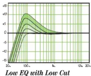
line
| x | y | |-------|--------| | 20x | -15.0 | | 100x | +10.0 | | 1x | 0.0 | | 10x | 0.0 | | 20x | 0.0 |26. Mid EQ
Short for “midrange,” this knob provides 15 dB of boost or cut, centered at 2.5 kHz, also flat at the center detent. Midrange EQ is often thought of as the most dynamic, because the frequencies that define any particular sound are almost always found in this range. You can create many interesting and useful EQ changes by turning this knob down as well as up.

line
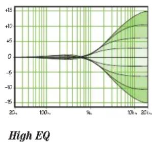
| x | y | | ---- | ------ | | 20 | 0 | | 100 | 0 | | 1k | 0 | | 10k | 0 | | 20k | 0 |27. Hi EQ
This control gives you up to 15 dB boost or cut above 12 kHz, and it is also flat at the detent. Use it to add sizzle to cymbals, and an overall sense of transparency, or edge to keyboards, vocals, guitar and bacon frying. Turn it down a little to reduce sibilance, or to hide tape hiss.
line
| x | y | |-------|--------| | 20% | 0 | | 100% | 0 | | % | 0 | | 10k | +10 | | 20k | -15 |
Moderation During EQ
With EQ, you can also upset things royally. We've designed a lot of boost and cut into each equalizer circuit, because we know everyone will occasionally need that. But if you max the EQs on every channel, you'll get mix mush. Equalize subtly and use the left sides of the knobs (cut), as well as the right (boost). Very few gold-record-album engineers ever use more than about 3 dB of EQ. If you need more than that, there's usually a better way to get it, such as placing a mic differently (or using a different kind of mic or singer entirely).
28. Aux
These knobs allow you to tap a portion of each channel signal out to another source for parallel effects processing or stage monitoring. Aux send levels are controlled by these knobs and by the aux master [37].
These are more than just effects and monitor sends. They can be used to generate separate mixes for recording or "mix-minuses" for broadcast. By using aux in the pre mode, these mix levels can be obtained independently of the channel's level control.
Aux in post mode is post-low cut, post-EQ and post-level. That is, the aux send obeys the settings of these controls. Aux in pre mode follows the EQ and low cut settings only. Pan and level have no effect on the pre send.
The aux send level ranges from off through unity (the center position) on up to 15 dB of extra gain (when turned fully clockwise). Chances are you'll never need this extra gain, but it's nice to know it's there if you do.
The channel 3–8 aux knobs control the mono sum of the channel's stereo signals for each aux send. For instance, channel 5 (L) and 6 (R) mix together to feed that channel's aux send knob.
Still with us? Good for you. Here come the tricky parts, the output or master section where the mixing is really done.
Output Section

flowchart
graph TD
    A["32 CR / SUBMIX"] --> B["33 ASSIGN TO MAIN MIX"]
    B --> C["30 MAIN MIX"]
    C --> D["37 AUX MASTER"]
    D --> E["39 POWER"]
    E --> F["36 PRE POST"]
    G["34 RUDE SOLO"] --> H["35 LEFT RIGHT"]
    H --> I["34 LEVEL SET"]
    I --> J["33 MAIN MIX"]
    J --> K["32 MAX PHONES"]
    K --> L["31 CONTROL ROOM SOURCE"]
29. Main Mix
This knob controls the levels of signals sent to the main outputs: XLR [17] and 1/4" [16] and RCA tape output [14]. All channels and stereo returns [8] that are not muted or turned fully down will wind up in the main mix.
Fully counterclockwise is off, the center is unity gain, and fully clockwise provides 12 dB of additional gain. This additional gain will typically never be needed, but once again, it's nice to know it's there. This is the knob to turn down at the end of the song when you want "The Great Fade-Out."
30. Control Room Source Matrix
Typically, the engineer sends the main mix to an audience (if live) or a mixdown deck (if recording). But what if the engineer in the control room needs to hear something other than the main mix? With the 802VLZ4, the engineer has several choices of what to listen to. This is one of those tricky parts, so brace yourself.
With these source switches, you can choose to listen to any combination of main mix, alt 3-4 and tape. By now, you probably know what the main mix is. Alt 3-4 is that additional stereo mix bus. Tape is the stereo signal coming in from the tape input [13] jacks.
Selections made in the source matrix deliver stereo signals to the control room, phones and meter display. With no switches engaged, there will be no signal at these outputs and no meter indication.
The exception is the solo function. Regardless of the source selection, engaging a channel's solo [22] switch will replace that selection with the solo signal, also sent to the control room, phones and meters. This is what makes the getting started procedure so easy to do.
Warning: Engaging both the tape and assign to main mix [33] button can create a feedback path between tape input [13] and tape output [14]. Make sure your tape deck is not in record, record-pause, or input-monitor mode when you engage these switches, or make sure the control room / submix [32] level knob is fully counterclockwise (off).
Now you know how to select the signals to send to the engineer's control room or phones.
31. Phones
This knob controls the level going to your stereo headphones. Make sure this is fully down whenever you are making connections in your system, or putting on the headphones. Bring up the level slowly and carefully to protect your hearing.
This dedicated phones level knob makes it is easy to turn down the studio monitors and listen just with the headphones, when overdubbing, or when in a room full of sleeping and hungry leopards.
32. Control Room/Submix
This knob controls the level of the stereo control room outputs [10]. The control range is from off through unity gain at the center, with 10 dB of extra gain when turned fully clockwise.
When main mix is your control room source selection, those signals will now pass through three level controls on the way to your control room amp and phones: the main mix [29] knob, this control room / submix knob, and the phones knob [31]. This way, you can send a nice healthy level to the main output (main mix knob at "U"), and a quiet level to the control room or phones (control room / submix knob and phones knob where you like).
When alt 3-4 or tape is selected, or a channel solo [22] is engaged, the control room / submix knob and phones knob will be the only ones controlling these levels (channel controls not withstanding).

flowchart
graph TD
    A["32 CR / SUBMIX"] --> B["33 ASSIGN TO MAIN MIX"]
    B --> C["30 CONTROL ROOM SOURCE"]
    C --> D["39 POWER"]
    D --> E["37 AUX MASTER"]
    E --> F["36 PRE POST"]
    G["34 RUDE SOLO"] --> H["35 LEFT RIGHT"]
    H --> I["34 LEVEL SET"]
    I --> J["33 MAIN MIX"]
    K["32 MAX PHONES"] --> L["31 MAIN MIX"]
Whatever your selection, you can also use the control room [10] outputs for other applications. Its sound quality is just as impeccable as the main outs [16 and 17]. It can be used as additional main mix output, which may sound silly since there are already three, but this one has its own level control. However, should you do something like this, be sure that you do not engage a solo switch, as that will interrupt your source selection.
A Word About Pre-Fader Solo (PFL)
Engaging a channel's solo [22] switch will cause this dramatic turn of events: any existing control room source selections will be replaced by the solo signal, appearing in the control room, headphones, and in the meter. The audible solo levels are then controlled by the control room / submix [32] knob and phones [31] knob. The solo levels appearing on the meter display are not controlled by anything — you wouldn't want that. You want to see the actual channel level on the meter regardless of how loud you're listening.
"Pre-fader" solo means that the channel signal is being tapped before the channel's level [21] knob. It does, however, obey gain [7], low cut [5] and EQ [25–27] settings, making it the perfect tool for quick inspections of suspect channels. The channel's pan [24] and mute/alt 3-4 [23] settings have no effect on the solo signal.
Note: for stereo channels 3-8, the solo signal is the mono sum of the left (odd-numbered) and right (even-numbered) signals for that channel strip.
Warning: Pre-fader solo [22] taps the channel signal before the level knob. If you have a channel's level knob set below "U" solo won't know that, and will send a unity gain signal to the control room, phones and meter display, that may result in a startling level boost at these outputs.
33. Assign to Main Mix
Let's say you're doing a live show. Intermission is nearing and you'll want to play a soothing CD for the crowd to prevent them from eating the furniture. Then you think, "But I have the CD player plugged into the tape inputs, and that never gets to the main outs!" Oh, but it does. Simply engage this switch and your control room source selection, after going through the control room / submix [32] knob, will feed into the main mix, just as if it were another stereo channel.
Another handy use for this switch is to enable the alt 3-4 mix to become a submix of the main mix, using the control room/submix knob as its level control.
Side effects: (1) engaging this switch will also feed any soloed channels into the main mix, which may be the last thing you want. (2) If you have the main mix as your control room source selection and then engage assign to main mix, the main mix lines to the control room will be interrupted to prevent feedback. Then again, why would anyone want to assign the main mix to the main mix?
34. Rude Solo
If you happen to forget you're in solo, you can easily be tricked into thinking that something is wrong with your mixer. Hence the flashing rude solo light. This will come on whenever a channel solo switch [22] is engaged.
It's especially handy at about 3 a.m. when no sound is coming out of your monitors but your multitrack is playing back like mad.
35. Meters
The 802VLZ4's peak metering system is made up of two columns of twelve LEDs. Deceptively simple, considering the multitude of signals that can be monitored by it.
If nothing is selected in the source matrix and no channels are in solo, the meters will just sit there and do nothing. To put them to work, you must make a selection in the source matrix [30], or engage a solo switch [22]. Why? You want the meter display to reflect what the engineer is listening to, and as we've covered,
the engineer is listening either to the control room [10] outputs or the phones [11] outputs. The only difference is that while the listening levels are controlled by the control room / submix [32] knob, the meters read the source mix before that control, giving you the real facts at all times, even if you're not listening at all.
Thanks to the 802VLZ4's wide dynamic range, you can get a good mix with peaks flashing anywhere between -20 and +10 dB on the meters. Most amplifiers clip at about +10 dB, and some recorders aren't so forgiving either. For best real-world results, try to keep your peaks between "0" and "+6".
Remember, audio meters are just tools to help assure you that your levels are “in the ballpark.” You don’t have to stare at them (unless you want to).
A Word About Aux
Sends are outputs, and returns are inputs. The channel aux [28] knobs taps the signal off each channel. The sum of the aux signals is sent to the aux master [37] knob before going to the aux send [15] output.
This output can be fed to the inputs of a reverb or other device. From there, the outputs of this external device are fed back to the mixer's stereo return [8] jacks, through the stereo return [38] level control, and finally delivered to the main mix.
So, the original “dry” signals go from the channels to the main mix, and the affected “wet” signals go from the stereo return [8] to the main mix. Once mixed together, the dry and wet signals combine to create a glorious sound. So, armed with this knowledge, let’s visit the auxiliary world:
36. Pre or Post (Aux)
Besides being used to work effects into your mix, aux sends serve another critical role — that of delivering cue mixes to stage monitors, so musicians can hear what they're doing. On the 802VLZ4, aux send can play either role, depending on the position of this switch.
With this switch out (disengaged), aux send will tap a channel pre-fader and pre-mute/alt 3-4, meaning that no matter how you manipulate those controls as they feed the main mix, the aux send will continue to belt out that channel's signal. This is the preferred method for setting up stage monitor feeds, as its level is not affected by changes to the channel's level controls. EQ settings will affect all aux sends. It's a bit like setting up two PAs, one at a nice level to keep your band happy, and one at a nice level to play to your audience. The levels of each are independent of each other.
With the switch in, the aux send becomes an ordinary effects send — post-fader (level) and post-mute/alt 3-4. This is a must for effects sends, since you want the levels of your "wet" signals to follow the level of the "dry," keeping them at the same ratio. For example, you do not want a returned echo to stay at one level, when you turn a channel down; you want it to go down as well. Post mute/alt 3-4 means that when a channel is muted, its aux send to an external processor is also muted.
37. Aux Master Send
This knob provides overall level control of aux send, just before it's delivered to the aux send [15] output. This knob goes from off (turned fully down), to unity gain at the center, with 10 dB of extra gain (turned fully up). You may never need the additional gain, but here it is anyway.
This is the knob to turn up when the lead singer glares at you, points at his stage monitor, and sticks his thumb up in the air. (If he stuck his thumb down, you'd turn the knob down, but that never happens.)
38. Stereo Return
This control sets the overall level of effects received from the stereo return [8] inputs. This could be the affected (wet) processed signal returning from an effects processor, or the stereo signals from another synth or source. This control is designed to handle a wide range of signal levels, from off, to unity gain at the center, with 20 dB gain fully clockwise, to compensate for low-level effects or sources.
Normally, set this knob at the center, and set the effects device or source's output control to whatever they call unity gain (check their manual). If that turns out to be too loud or too quiet, adjust the effects device or source's outputs, not the mixer. That way, the mixer's knobs are easy to relocate at the center.
Signals passing through this control proceed directly to main mix. The stereo returns do not have mute/alt 3-4 switches, so if you want these signals to get to the alt 3-4 mix, you'll have to patch the effects device's outputs into one of the stereo channels instead of the stereo return, and mute/alt those channels.
39. Power LED
This LED will light when the mixer is connected to a live power supply, and the power switch is turned on. This lets you know that the mixer's internal circuits are turned on, and all ready for action.
Turning off the power switch will turn off the mixer and this LED will go out.
Congratulations! You've just read about all the features of your 802VLZ4. You're probably ready for a cold one. Go ahead. The rest of the manual can wait.
Appendix A: Service Information
If you think your 802VLZ4 has a problem, please check out the following troubleshooting tips and do your best to confirm the problem. Visit the support section of our website (www.720trees.com) where you will find lots of useful information such as FAQs and other documentation. You may find the answer to the problem without having to send your mixer away.
Troubleshooting
Bad Channel
• Is the gain set correctly?
• Is the level knob turned up?
- Is the instrument switch set correctly? (Channels 1–2 only).
- Try the same source signal in another channel, set up exactly like the suspect channel.
- Check that the pan knob is set correctly.
• Check the EQ and the low-cut switch.
Bad Output
• Is the associated level knob (if any) turned up?
- If it's one of the main outs, try unplugging all the others. For example, if it's the 1/4" left main out, unplug the RCA and XLR left outputs. If the problem goes away, its not the mixer.
- If a left speaker is presumed dead, switch the left and right cords, at the mixer's main outs. If the left speaker is still not working, it's not the mixer.
Noise
- Turn the channel level and aux return knobs down, one by one. If the sound disappears, it's either that channel or whatever is plugged into it, so unplug whatever that is. If the noise disappears, it's from your whatever.
Power
- Check that the supplied power supply is connected to a live AC outlet. The power LED on the mixer should come on when the power switch is on.
Repair
For warranty service, please refer to the warranty information on page 27.
Non-warranty service is available at a factory-authorized service center. To locate the nearest service center, visit www.720trees.com, click "Contact Tech Support" and select "Locate a Service Center or Distributor" [3]. Service for an 802VLZ4 living outside the United States may be obtained through local dealers or distributors.
If you do not have access to our website, you can call our Tech Support department at 1-800-898-3211, Monday-Friday, during normal business hours, Pacific Time, to explain the problem. Tech Support will tell you where the nearest factory-authorized service center is located in your area.
Appendix B: Connections
Balanced XLR Input Connector
The 802VLZ4 mixer has three female XLR inputs. Be sure the cables are wired per AES (Audio Engineering Society) standards:
Balanced XLR Input Connector
Pin 1 - Shield (Ground)
Pin 2 - Positive (+ or hot)
Pin 3 - Negative (- or cold)

Balanced XLR Input Connector
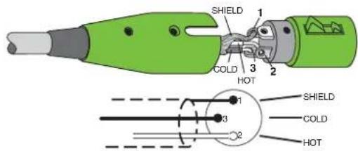
Balanced XLR Output Connector
The male XLR connectors provide a balanced line-level signal that represents the end of the mixer, where the fully mixed stereo signal enters the real world. Connect these to the left and right line-level inputs of powered speakers or to the left and right line-level inputs of an amplifier (with speakers already attached).
Be sure the cables are wired per AES (Audio Engineering Society) standards:
Balanced XLR Output Connector
Pin 1 – Shield (Ground) Pin 2 – Positive (+ or hot) Pin 3 – Negative (- or cold)
Balanced XLR Output Connector
Balanced 1/4" TRS Connector
TRS stands for Tip-Ring-Sleeve, the three connections available on a stereo 1/4" cable. This allows for a direct connection to the channel input jacks. Be sure the cables are wired per AES (Audio Engineering Society) standards:
Balanced 1/4" TRS Connector
Sleeve - Shield (Ground) Tip - Positive (+ or hot) Ring - Negative (- or cold)

Balanced 1/4" TRS Connector
TRS jacks and plugs are used in several different applications:
- Balanced mono circuits. When wired as a balanced connector, a 1/4" TRS jack or plug is connected tip to signal high (hot), ring to signal low (cold), and sleeve to ground (earth).
- Stereo Headphones, and rarely, stereo microphones and stereo line connections. When wired for stereo, a 1/4" TRS jack or plug is connected tip to left, ring to right and sleeve to ground (earth). VLZ4 mixers do not directly accept 1-plug-type stereo micro phones. They must be separated into a left cord and a right cord, which are plugged into the two mic preamps.
You can cook up your own adapter for a stereo microphone. "Y" two cables out of a female 1/4" TRS jack to two male XLR plugs, one for the right signal and one for the left.
- Unbalanced send/return circuits. When wired as a send/return "Y" connector, a 1/4" TRS jack or plug is connected tip to signal send (output from mixer), ring to signal return (input back into mixer), and sleeve to ground (earth).
Unbalanced 1/4" TS Connector
TS stands for Tip-Sleeve, the two connections available on a mono 1/4" cable. This allows for a direct convection to the channel input jacks. Be sure the cables are wired per AES (Audio Engineering Society) standards:
Unbalanced 1/4" TS Connector
Sleeve - Shield (Ground) Tip - Positive (+ or hot)
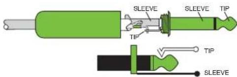
Unbalanced 1/4" TS Connector
TS jacks and plugs are used in many different applications, always unbalanced. The tip is connected to the audio signal and the sleeve to ground (earth). Some examples:
• Unbalanced microphones
• Electric guitars and electronic instruments
• Unbalanced line-level connections
Unbalanced RCA Connector
RCA-type plugs (also known as phono plugs) and jacks are often used in home stereo and video equipment and in many other applications. RCA plugs are unbalanced. Connect the signal to the center post and the ground (earth) or shield to the surrounding "basket." Be sure the cables are wired per AES (Audio Engineering Society) standards:
Unbalanced RCA Connector
Sleeve - Shield (Ground) Tip - Positive (+ or hot)

Unbalanced RCA Connector
TRS Send/Receive Insert Jacks
Single-jack inserts are three-conductor, TRS-type 1/4" phone. They are unbalanced, but have both the mixer output (send) and the mixer input (return) signals in one connector. See the illustration below.
The sleeve is the common ground (earth) for both signals. The send from the mixer to the external unit is carried on the tip, and the return from the unit to the mixer is on the ring.

flowchart
graph LR
    A["tip"] --> B["ring"]
    B --> C(sleeve)
    C --> D["(TRS plug)"]
    D --> E["This plug connects to one of the mixer's Channel Insert jacks."]
    E --> F["SEND to processor"]
    F --> G["tip"]
    F --> H["RETURN from processor"]
    H --> I["ring"]
Unbalanced 1/4" Insert Connectors
Using the Send Only on an Insert Jack
If you insert a TS (mono) 1/4" plug only partially (to the first click) into a VLZ4 insert jack, the plug will not activate the jack switch and will not open the insert loop in the circuit (thereby allowing the channel signal to continue on its merry way through the mixer).
This allows you to tap out the channel or bus signal without interrupting normal operation.
If you push the 1/4" TS plug in to the second click, you will open the jack switch and create a direct out, which does interrupt the signal in that channel. See the illustration below.
NOTE: Do not overload or short-circuit the signal you are tapping from the mixer. That will affect the internal signal.

Using the Send Only on an Insert Jack
VLZ4 Stereo Inputs and Returns: Mono, Stereo, Whatever
Stereo line inputs and stereo returns are a fine example of our philosophy (which we just made up) of Maximum Flexibility with Minimum Headache. The inputs and returns will automatically be mono or stereo, depending upon how you use the jacks. Here's how it works:
A mono signal should be patched into the input or return jack labeled left (mono). The signal will be routed to both the left and right sides of the return circuit, and will show up in the center of the stereo pair of buses it's assigned to, or it can be panned with the pan [24] control.
A stereo signal, having two plugs, should be patched into the left (mono) and the right input or return jacks. A jack switch in the right jack will disable the mono function, and the signals will show up in stereo.
A mono signal connected to the right jack will show up in the right bus only. You probably will only want to use this sophisticated effect for special occasions.
Microphone Stand
The bottom panel of the 802VLZ4 has three non-threaded holes that allow it to be fitted with an optional microphone stand adapter. This allows you to support the mixer on a standard mic stand, and adjust its height and level to whatever suits your strangely-complex set of preferences.
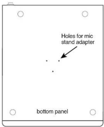
- Order the Atlas AD-11B mic stand adapter available from many a fine music store. (It is made and distributed by Atlas Sound.)
- Use three self-tapping machine screws 6-32 x 1/4" long to secure the adapter to the bottom of the 802VLZ4.

Do not use screws that are longer then 1/4" as these could damage the circuit boards. Do not use any shorter screws, or the adapter will not be securely fixed to the mixer.
Appendix C: Technical Information
Specifications
Main Mix Noise
(20 Hz–20 kHz bandwidth, channels 1–3 gain @ unity gain, channel EQ flat, all channels assigned to main mix, channel 1 panned left, 2 panned right, 3–8 centered.)
Main mix knob down, channel level knobs down:
XLR: -95
TRS: -101
Main mix knob unity, channel level knobs down:
XLR: -90
TRS: -96
Main mix knob @ unity, channel level knobs @ unity:
XLR: -84
TRS: -90
Total Harmonic Distortion (THD)
(1 kHz @ 30 dB gain, 20 Hz–20 kHz bandwidth)
Mic pre @ insert: 0.001%
Attenuation (Crosstalk)
(1 kHz relative to 0 dBu, 20 Hz–20 kHz bandwidth, line in, 1/4" main out, gain @ unity.)
Main mix knob down: -75 dBu
Channel Alt / Mute switch engaged: -100 dBu
Channel level knob down: -100 dBu
Frequency Response
(30 Hz to 30 kHz, mic input to any output, @ 60 dB gain.)
+0
(10 Hz to 100 kHz, mic input to any output, @ unity gain.)
+0
Equivalent Input Noise (EIN)
(20 Hz–20 kHz, mic input to insert send out, max gain.)
150 Ω termination: -128.5 dBu

Common Mode Rejection Ratio (CMRR)
(Mic in to insert send out, max gain.)
1 kHz: better than -70 dB
Maximum Levels
dBu in: +21 dBu
^dBu Tape in: +22 dBu
dBrother inputs: +22 dBu
dBu Main mix XLR out: +28 dBu
All other outputs: +22 dBu
dBu
Impedances
Mic in: 2.55 k Ω
Channel insert return: 5 k Ω
All other inputs: 17 k or greater Ω
Tape out: 1 k Ω
Phones out: Ω 60
All other outputs: 120 Ω
EQ
High Shelving ±15 dB @ 12 kHz
Mid Peaking ±15 dB @ 2.5 kHz
Low Shelving ±15 dB @ 80 Hz
Power Consumption
dB/-1 dB 13 watts
dB/-3 Dimensions (H x W x D)
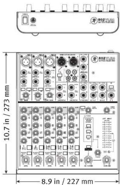
10.7" x 8.9" x 1.8" (273 mm x 227 mm x 47 mm)
Weight
With power supply 5.5 lb (2.5 kg)
Without power supply 4.5 lb (2.0 kg)
Since we are always striving to make our products better by incorporating new and improved materials, components, and manufacturing methods, we reserve the right to change these specifications at any time without notice.
The "Running Man" figure is a registered trademark of LOUD Technologies Inc. All other brand names mentioned are trademarks or registered trademarks of their respective holders, and are hereby acknowledged.
©2013 LOUD Technologies Inc. All Rights Reserved.
Block Diagram

flowchart
graph TD
    subgraph Channel_1
        A["Mono Channels Ch 1/2"] --> B["Line"]
        B --> C["Gain"]
        C --> D["HPF"]
        D --> E["3-Band E Q"]
        E --> F["Level"]
        F --> G["Aux sends"]
        G --> H["solo"]
        H --> I["Aux sends"]
        I --> J["3-Band E Q"]
    end

    subgraph Channel_2
        K["Hybrid channel 3/4"] --> L["HPF"]
        L --> M["L"]
        M --> N["R"]
        N --> O["3-Band E Q"]
        O --> P["Level"]
        P --> Q["Aux sends"]
        Q --> R["solo"]
        R --> S["Aux sends"]
        S --> T["solo"]
        T --> U["Aux sends"]
    end

    subgraph Channel_3
        V["Stereo channels 5/6 and 7/8"] --> W["L"]
        W --> X["R"]
        X --> Y["3-Band E Q"]
        Y --> Z["Level"]
        Z --> AA["Aux sends"]
        AA --> AB["solo"]
        AB --> AC["Aux sends"]
        AC --> AD["solo"]
        AD --> AE["Aux sends"]
    end

    subgraph Channel_4
        AF["Tape"] --> AG["Line"]
        AH["Line"] --> AI["Bal"]
        AJ["Line"] --> AK["Right"]
        AL["Tape"] --> AM["Line"]
        AN["Line"] --> AO["Tape"]

    subgraph Channel_5
        AP["Tape"] --> AQ["Line"]
        AR["Line"] --> AS["Bal"]
        AT["Line"] --> AU["Right"]
        AV["Line"] --> AW["Tape"]

    subgraph Channel_6
        AX["Tape"] --> AY["Line"]
        AZ["Line"] --> BA["Bal"]
        BB["Bal"] --> BC["Line"]
        BD["Tape"] --> BE["Line"]

    subgraph Channel_7
        BF["Tape"] --> BG["Line"]
        BH["Line"] --> BI["Bal"]
        BJ["Tape"] --> BK["Line"]

    subgraph Channel_8
        BL["Tape"] --> BM["Line"]
        BN["Tape"] --> BO["Bal"]
        BP["Tape"] --> BQ["Bal"]

    subgraph Channel_9
        BR["Tape"] --> BS["Line"]
        BT["Tape"] --> BU["Bal"]
        BV["Tape"] --> BW["Tape"]

    subgraph Channel_10
        CA["Tape"] --> CB["Line"]
        CC["Tape"] --> CD["Bal"]
        DE["Tape"] --> DF["Line"]

    subgraph Channel_11
        DG["Tape"] --> DH["Line"]
        DI["Tape"] --> DJ["Bal"]
        DK["Tape"] --> DL["Line"]

    subgraph Channel_12
        DM["Tape"] --> DN["Line"]
        DO["Tape"] --> DOA["Bal"]
        DP["Tape"] --> DPQ["Bal"]

    subgraph Channel_13
        EQ["Tape"] --> R["Tape"]
        SD["Tape"] --> SDQ["Bal"]

    subgraph Channel_14
        SE["Tape"] --> SEQ["Line"]
        SEQ --> SC["Bal"]

    subgraph Channel_15
        SDT["Tape"] --> SDU["Bal"]

    subgraph Channel_16
        DU["Tape"] --> DUQ["Bal"]

    subgraph Channel_17
        DV["Tape"] --> DVQ["Bal"]

    subgraph Channel_18
        DVQ["Tape"] --> DVQQ["Bal"]

    subgraph Channel_19
        DVQT["Tape"] --> DVQTS["Bal"]

    subgraph Channel_20
        DVQT["Tape"] --> DVQTQ["Bal"]

    subgraph Channel_21
        DVQTQ["Tape"] --> DVQTTSB["Bal"]

    subgraph Channel_22
        DVQTTSB["Tape"] --> DVQTTSBQ["Bal"]

    subgraph Channel_23
        DVQTTSBQ["Tape"] --> DVQTTSBQQ["Bal"]

    subgraph Channel_24
        DVQTTSBQTSB["Bal"] --> DVQTTSBQTSBQ["Ba"]
    end

    subgraph Channel_25
        DVQTTSBTSBTSB["Ba"] --> DVQTTSBTSBTSBQTSB
    end

    subgraph Channel_26
        DVQTTSBTSBTSBTSBTSB
    end

    subgraph Channel_27
        DVQTTSBTSBTSBTSBTSBTSB
    end

    subgraph Channel_28
        DVQTTSBTSBTSBTSBTSBTSB
    end

    subgraph Channel_29
        DVQTTSBTSBTSBTSBTSBTSB
    end

    subgraph Channel_30
        DVQTTSBTSBTSBTSBTSBTSB
    end

    subgraph Channel_31
        DVQTTSBTSBTSBTSBTSBTSB
    end

    subgraph Channel_32
        DVQTTSBTSBTSBTSBTSBTSB
    end

    subgraph Channel_33
        DVQTTSBTSBTSBTSBTSBTSB
    end

    subgraph Channel_34
        DVQTTSBTSBTSBTSBTSBTSB
    end

    subgraph Channel_35
        DVQTTSBTSBTSBTSBTSBTSB
    end

    subgraph Channel_36
        DVQTTSBTSBTSBTSBTSBTSB
    end

    subgraph Channel_37
        DVQTTSBTSBTSBTSBTSBTSB
    end

    subgraph Channel_38
        DVQTTSBTSBTSBTSBTSBTSB
    end

    subgraph Channel_39
        DVQTTSBTSBTSBTSBTSBTSB
    end

    subgraph Channel_40
        DVQTTSBTSBTSBTSBTSBTSB
    end

    subgraph Channel_41
        DVQTTSBTSBTSBTSBTSBTSB
    end

    subgraph Channel_42
        DVQTTSBTSBTSBTSBTSBTSB
    end

    subgraph Channel_43
        DVQTTSBTSBTSBTSBTSBTSB
    end

    subgraph Channel_44
        DVQTTSBTSBTSBTSBTSBTSB
    end

    subgraph Channel_45
        DVQTTSBTSBTSBTSBTSB<fcel>Aux 1 sum → Aux 1 level → Aux 1 out

    note right of main: Switches are shown in default (out) position.
802VLZ4 Limited Warranty
Please keep your sales receipt in a safe place.
This Limited Product Warranty (“Product Warranty”) is provided by LOUD Technologies Inc. (“LOUD”) and is applicable to products purchased in the United States or Canada through a LOUD-authorized reseller or dealer. The Product Warranty will not extend to anyone other than the original purchaser of the product (hereinafter, “Customer,” “you” or “your”).
For products purchased outside the U.S. or Canada, please visit www.720trees.com to find contact information for your local distributor, and information on any warranty coverage provided by the distributor in your local market.
LOUD warrants to Customer that the product will be free from defects in materials and workmanship under normal use during the Warranty Period. If the product fails to conform to the warranty then LOUD or its authorized service representative will at its option, either repair or replace any such nonconforming product, provided that Customer gives notice of the noncompliance within the Warranty Period to the Company at: www.720trees.com or by calling LOUD technical support at 1.800.898.3211 (toll-free in the U.S. and Canada) during normal business hours Pacific Time, excluding weekends or LOUD holidays. Please retain the original dated sales receipt as evidence of the date of purchase. You will need it to obtain any warranty service.
For full terms and conditions, as well as the specific duration of the Warranty for this product, please visit www.720trees.com.
The Product Warranty, together with your invoice or receipt, and the terms and conditions located at www.720trees.com constitutes the entire agreement, and supersedes any and all prior agreements between LOUD and Customer related to the subject matter hereof. No amendment, modification or waiver of any of the provisions of this Product Warranty will be valid unless set forth in a written instrument signed by the party to be bound thereby.

Correct disposal of this product. This symbol indicates that this product should not be disposed of with your household waste, according to the WEEE Directive (2002/96/EC) and your national law. This product should be handed over to an authorized collection site for recycling waste electrical and electronic equipment (EEE). Improper handling of this type of waste could have a possible negative impact on the environment and human health due to potentially hazardous substances that are generally associated with EEE. At the same time, your cooperation in the correct disposal of this product will contribute to the effective usage of natural resources. For more information about where you can drop off your waste equipment for recycling, please contact your local city office, waste authority, or your household waste disposal service.

MACKIE.
16220 Wood-Red Road NE
Woodinville, WA 98072 • USA
Phone: 425.487.4333
Toll-free: 800.898.3211
Fax: 425.487.4337
www.720trees.com
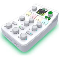


- 8-Channel Ultra-Compact Mixer
- OWNER'S MANUAL
- Important Safety Instructions
- Contents
- Features
- Introduction
- How To Use This Manual
- Need help with your mixer?
- Getting Started
- Things to Remember
- Hookup Diagrams
- Live Band PA System
- Home Studio
- Keyboard Submixer
- Combined Home Studio and Home Theater
- Patchbay Description
- Mic Ins (Channels 1–3)
- Phantom Power
- Line Ins (Channels 1–2)
- Stereo Line Ins (Channels 3–4, 5–6, and 7–8)
- Channel Insert (Channels 1–2)
- Low Cut (Channels 1–3)
- Instrument Switch (Channels 1–2)
- Gain (Channels 1–3)
- Effects: Serial or Parallel?
- Stereo Return
- Alt 3–4 Outs
- Control Room Outs
- Phones
- Phantom Switch and Led
- Tape In
- Tape Out
- Aux Send
- 1/4" Main Outs
- XLR Main Outs
- XLR Main Out Level Switch
- Power Connection
- Power Switch
- Channel Strip Description
- "U" Like Unity Gain
- Level
- Pre Fader Solo
- Mute/Alt 3-4
- Pan
- Constant Loudness !!!
- 3-Band EQ
- Low EQ
- Mid EQ
- Hi EQ
- Moderation During EQ
- Aux
- Output Section
- Main Mix
- Control Room Source Matrix
- Phones
- Control Room/Submix
- A Word About Pre-Fader Solo (PFL)
- Assign to Main Mix
- Rude Solo
- Meters
- A Word About Aux
- Pre or Post (Aux)
- Aux Master Send
- Stereo Return
- Power LED
- Appendix A: Service Information
- Troubleshooting
- Bad Channel
- Bad Output
- Noise
- Power
- Repair
- Appendix B: Connections
- Balanced XLR Input Connector
- Balanced XLR Output Connector
- Balanced 1/4" TRS Connector
- Unbalanced 1/4" TS Connector
- Unbalanced RCA Connector
- TRS Send/Receive Insert Jacks
- Using the Send Only on an Insert Jack
- VLZ4 Stereo Inputs and Returns: Mono, Stereo, Whatever
- Microphone Stand
- Appendix C: Technical Information
- Specifications
- Main Mix Noise
- Total Harmonic Distortion (THD)
- Attenuation (Crosstalk)
- Frequency Response
- Equivalent Input Noise (EIN)
- Common Mode Rejection Ratio (CMRR)
- Maximum Levels
- Impedances
- EQ
- Power Consumption
- dB/-3 Dimensions (H x W x D)
- Weight
- Block Diagram
- 802VLZ4 Limited Warranty
- Please keep your sales receipt in a safe place.
- MACKIE.
Brand : MACKIE
Model : 802VLZ4
Category : Mixer