
PPC2000 - Multimedia Cart Chief - Free user manual and instructions
Find the device manual for free PPC2000 Chief in PDF.


| Product Type | Plasma Presenters Cart (PPC) |
| Brand | Chief |
| Model | PPC2000 |
| Weight Capacity | 200 lbs (90.7 kg) |
| Height Adjustment | 2-inch increments |
| Mounting Plate | Universal (accepts Chief PSB mounting brackets) |
| Base Material | Steel tubing (2.5" diameter) |
| Casters | Four (2 locking, 2 non-locking), 4" twin wheel |
| Accessory Shelves | Optional smoked acrylic |
| Cable Management | Access holes in base for cords |
| Color | Black (assumed) |
| Assembly Required | Yes |
| Tools Required | 7/16", 1/2", 3/4" wrenches, Allen wrenches, socket set, Phillips screwdriver |
| Safety Features | Locking casters, two-person installation required |
| Intended Use | Showrooms, boardrooms, trade show exhibits |
| Floor Surface | Smooth, flat surfaces only (not for ramps) |
| Cleaning Instructions | Avoid harsh cleaners on acrylic shelves; use mild soap |
| Mounting Compatibility | All Chief PSB brackets |
| Locking Provision | Faceplate holes for padlock or pin lock |
| Included Hardware | Nuts, washers, screws, cap plugs, Allen wrench |
Frequently Asked Questions - PPC2000 Chief
User questions about PPC2000 Chief
0 question about this device. Answer the ones you know or ask your own.
Ask a new question about this device
Download the instructions for your Multimedia Cart in PDF format for free! Find your manual PPC2000 - Chief and take your electronic device back in hand. On this page are published all the documents necessary for the use of your device. PPC2000 by Chief.
USER MANUAL PPC2000 Chief
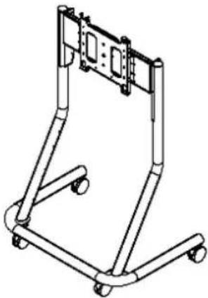
The Plasma Presenters Cart (PPC) is designed to assist the presenter in showrooms, boardrooms, and trade show exhibits. The PPC provides agile mobility for screens weighing up to 200 pounds while furnishing safe, stable support.
The attractive cart base is constructed of rugged 2.5" diameter steel tubing with optional smoked acrylic accessory shelves. Access holes, to conceal unsightly equipment cords or cables, are provided at several locations in the base. The standard two 4" twin wheel casters and two locking casters make movement easy yet prevent accidental movement of the screen.
The universal mounting plate accepts all Chief PSB mounting brackets. The 2" incremental height adjustment facilitates optimum viewing for most settings.
natural_image
Technical line drawing of a mechanical support frame with mounting feet and structural supports (no text or symbols)BEFORE YOU BEGIN
CAUTION: To prevent damage to the Plasma Deacantera Cart, which could affect or void the Exckenius

IMPORTANT WARNINGS and CAUTIONS!
WARNING: A WARNING alerts you to the possibility of serious injury or death if you do not follow the instructions.
CAUTION: A CAUTION alerts you to the possibility of damage or destruction of equipment if you do not follow the corresponding instructions.
- WARNING: Do not attempt to hang the Plasma Display Panel onto the cart alone. Always use two people to hang the display.
- WARNING: Always park the cart on a level surface. The locking wheels of the cart are not designed to hold the cart on an inclined surface.
- WARNING: Do not use the cart to transport your Plasma Display Panel on ramps or steep angles. The cart is designed to move on smooth, flat surfaces.
- CAUTION: Inspect the unit for shipping damage.
• CAUTION: Do not use cleanser or harsh cleaning agents on acrylic shelves.
TOOLS REQUIRED FOR INSTALLATION
- 7/16", 1/2", and 3/4" wrench
- Allen wrenches
- Socket set with extension
• Phillips screw driver
NOTE: Other tools may be required depending on the method of installation.
CONTENTS
INSPECT PARTS BEFORE ASSEMBLY ..... 2
Inspect The Cart 2
ASSEMBLE CART 3
MOUNT FLAT PANEL DISPLAY ON CART... 4
REMOVE DISPLAY FROM MOUNT...... 5
INSPECT PARTS BEFORE ASSEMBLY
Inspect The Cart
- Carefully inspect the cart for shipping damage. If any damage is apparent, call your carrier claims agent and do not continue with the assembly procedure until the carrier has reviewed the damage.
NOTE: Read all assembly instructions before starting assembly.
- Carefully inspect the Plasma Presenters Cart (PPC) components for damage (See Figure 1).
Item #
- BASE with corner supports
- LEG, right hand
- LEG, left hand
- HEAD, mounting, plasma assembly
- PLATE, face
- CASTER (locking quantity 2, non-locking quantity 2)
- NUTS, Nylock 1/4-20 (quantity 8)
- WASHERS, (quantity 2)
- NUT, Nylock, 10-24 (quantity 1 Not Shown)
- BRACKET, side (quantity 2)
- SCREWS, cap, button head, 1/4-20X5/8" (quantity 20)
- PLUG, cap (quantity 4)
- WRENCH, Allen, 5/32" (quantity 1 Not Shown)

- WASHER, Nylon (quantity 1 Not Shown)
- SCREW, 10-24X1/2" (quantity 1 Not Shown)
ASSEMBLE CART
Numbers in ( ) refer to parts shown in Figure 1 and Figure 2. Assemble cart as follows:
- Place base (10) upside down and thread two locking casters and two regular casters (60) into base (see Figure 3).
- Place base upright on casters. Install right leg (20) and left leg (30), making sure the mounting tabs face inward (see Figure 4). Secure legs using two 1/4" fender washers (80), two lock washers (81), and two 1/4-20X5/8" screws (90).
- Using eight 1/4-20X5/8" screws (90) and 1/4-20 Nylock nuts (70), secure each side bracket (82) to the mounting head (40) (see Figure 5).
- Using six 1/4-20X5/8" screws (90) secure the face plate (50) to the side brackets (82) (see Figure 5).
- Using four 1/4-20X5/8" buttonhead cap screws, two per side, secure the mounting head (40) to the top of the legs of the cart (see Figure 7).
- Install cap plugs in base (see Figure 4) and on top of each leg (see Figure 6).
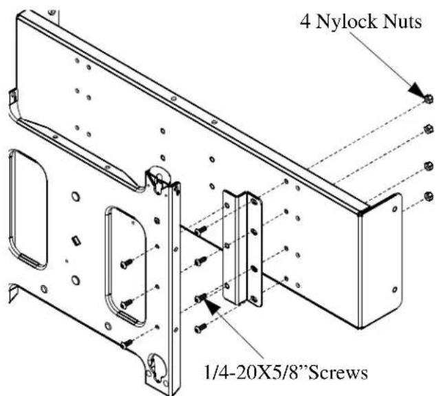
Figure 5. Face Plate and Mounting Head

Figure 3. Install Casters

Figure 4. Install Legs

Figure 6. Install Mounting Head and Cap Plugs
MOUNT PLASMA DISPLAY ON CART
- Install PSB bracket (not included) on plasma display according to instructions supplied with bracket.
WARNING: Do not attempt to hang the plasma display onto the cart with one person.
-
With the cart rolled up against a stable vertical surface, make sure the casters are locked.
-
While supporting both sides of display, align four mounting buttons on display or interface bracket with four mounting holes in head assembly. (See Figures 7 and 8)

natural_image
Technical diagram of a mechanical assembly with labeled components (no text or symbols present)Figure 7
WARNING: DISPLAY MAY WEIGH IN EXCESS OF 40 LBS! Always use two people and proper lifting techniques when installing or positioning display on stand.
- Lower display into place listening for audible "click" to ensure recessed area of mounting buttons are properly seated in lower area of mounting holes. (See Figures 7 and 8)
WARNING: IMPROPER INSTALLATION CAN LEAD TO DISPLAY FALLING CAUSING SERIOUS PERSONAL INJURY OR DAMAGE TO EQUIPMENT! Ensure mounting buttons are completely engaged in mounting holes.
NOTE: Holes are provided in the faceplate for use with a padlock or similar locking device, if desired. In addition, the pin and nut may be removed from the upper holes and moved to the lower holes for use as a more permanent locking device. (See Figure 8)

Figure 8.
REMOVING DISPLAY FROM MOUNT
- Remove bolt or padlock from faceplate (if used).
NOTE: The pin may have been used as a more permanent locking device. If so, remove nut and pin and move from the lower holes to the upper holes.
- Pull back on flag on upper mounting hole and press pin down into "Open" position. (See Figure 9)
WARNING: DISPLAY MAY WEIGH IN EXCESS OF 40 LBS! Always use two people and proper lifting techniques when installing or positioning display on mount.
-
Carefully lift display from mount.
-
Lift up on pin and place flag back against faceplate to return it to "Closed" position.


Figure 9.



Brand : Chief
Model : PPC2000
Category : Multimedia Cart