NPORT 6150 - Server Moxa - Free user manual and instructions
Find the device manual for free NPORT 6150 Moxa in PDF.


| Brand | Moxa |
| Model | NPORT 6150 |
| Product Type | Serial Device Server |
| Serial Ports | 1 RS-232/422/485 |
| Ethernet Port | 1 10/100BaseT(X) RJ45 |
| Input Voltage | 12 to 48 VDC |
| Power Consumption | 5.4 W (max) |
| Dimensions (W x H x D) | 80 x 111 x 25 mm |
| Weight | 0.3 kg |
| Operating Temperature | 0 to 60°C |
| Supported Protocols | TCP, UDP, DHCP, SNMP, HTTP, Telnet |
| Operating Mode | TCP Server, TCP Client, UDP, Pair Connection, Real COM |
| Serial Line Protection | 15 kV ESD for all signals |
| Configuration | Web browser, Telnet, Serial console, Windows utility |
| Certifications | CE, FCC, UL |
| Mounting | DIN-rail or wall mount |
| Maintenance | Clean with dry cloth; no user-serviceable parts |
| Repairability | Contact Moxa support for repair |
Frequently Asked Questions - NPORT 6150 Moxa
User questions about NPORT 6150 Moxa
0 question about this device. Answer the ones you know or ask your own.
Ask a new question about this device
Download the instructions for your Server in PDF format for free! Find your manual NPORT 6150 - Moxa and take your electronic device back in hand. On this page are published all the documents necessary for the use of your device. NPORT 6150 by Moxa.
USER MANUAL NPORT 6150 Moxa
NPort 6000 Series User's Manual
Edition 13.0, January 2016
www.moxa.com/product
MOXA®
© 2016 Moxa Inc. All rights reserved.
NPort 6000 Series User's Manual
The software described in this manual is furnished under a license agreement and may be used only in accordance with the terms of that agreement.
Copyright Notice
© 2016 Moxa Inc. All rights reserved.
Trademarks
The MOXA logo is a registered trademark of Moxa Inc.
All other trademarks or registered marks in this manual belong to their respective manufacturers.
Disclaimer
Information in this document is subject to change without notice and does not represent a commitment on the part of Moxa.
Moxa provides this document as is, without warranty of any kind, either expressed or implied, including, but not limited to, its particular purpose. Moxa reserves the right to make improvements and/or changes to this manual, or to the products and/or the programs described in this manual, at any time.
Information provided in this manual is intended to be accurate and reliable. However, Moxa assumes no responsibility for its use, or for any infringements on the rights of third parties that may result from its use.
This product might include unintentional technical or typographical errors. Changes are periodically made to the information herein to correct such errors, and these changes are incorporated into new editions of the publication.
Technical Support Contact Information
www.moxa.com/support
Moxa Americas
Toll-free: 1-888-669-2872
Tel: +1-714-528-6777
Fax: +1-714-528-6778
Moxa Europe
Tel: +49-89-3 70 03 99-0
Fax: +49-89-3 70 03 99-99
Moxa India
Tel: +91-80-4172-9088
Fax: +91-80-4132-1045
Moxa China (Shanghai office)
Toll-free: 800-820-5036
Tel: +86-21-5258-9955
Fax: +86-21-5258-5505
Moxa Asia-Pacific
Product Features 1-4
Product Selection Chart 1-4
Product Specifications 1-5
NPort 6150....1-5
NPort 6250/6250-S-SC/6250-M-SC 1-7
NPort 6450....1-9
NPort 6610/6650....1-11
2. Getting Started 2-1
Panel Layout 2-2
NPort 6150/6250....2-2
NPort 6450....2-2
NPort 6610/6650....2-3
Panel, DIN-Rail, and Rack Mounting 2-4
Connecting the Hardware 2-5
Wiring Requirements 2-5
Connecting the NPort 6600 VDC's Power 2-5
Grounding the NPort 6600 VDC....2-6
Connecting to the Network 2-6
Connecting to a Serial Device 2-6
LED Indicators 2-6
Adjustable Pull High/Low Resistors for the RS-485 Port 2-7
3. Initial IP Address Configuration.... 3-1
Static and Dynamic IP Addresses....3-2
Factory Default IP Address....3-2
Configuration Options....3-2
NPort Search Utility 3-2
Web Console 3-2
LCM Console/Front Panel (NPort 6610, 6650, and 6450 only) 3-2
ARP 3-3
Telnet Console 3-4
Serial Console 3-6
4. Introducing Serial Port Operation Modes 4-1
Overview 4-2
Guide to NPort 6000 Modes....4-2
Device-Control Applications....4-3
Real COM and Secure Real COM Modes 4-3
Reverse Real COM Mode....4-4
RFC2217 Mode....4-4
Socket Applications....4-5
TCP Server and Secure TCP Server Modes 4-5
TCP Client and Secure TCP Client Modes....4-5
UDP Mode 4-6
Pair Connection and Secure Pair Connection Modes....4-6
Ethernet Modem Mode....4-7
Terminal Applications 4-7
Terminal ASCII Mode....4-8
Terminal BIN Mode 4-8
SSH Mode 4-8
Reverse Terminal Applications....4-8
Reverse Telnet 4-9
Reverse SSH....4-9
Printer Modes....4-9
Dial In/Out Modes 4-10
Disabled Mode....4-10
5. Configuration with the Web Console 5-1
Using Your Web Browser....5-2
Browser Cookie Settings....5-2
Trusted Site Settings 5-3
Opening the Web Console....5-4
Web Console Navigation 5-5
Basic Settings 5-5
Server Settings 5-5
Time Settings 5-5
Network Settings 5-6
Basic Network Settings 5-6
Advanced Network Settings 5-9
Configuring the Route Table 5-10
- Module Settings 6-1
NM-TX01, NM-TX02, NM-FX01-M-SC, NM-FX01-S-SC, NM-FX02-M-SC, NM-FX02-S-SC....6-2
Using Ethernet Redundancy 6-2
The STP/RSTP Concept 6-3
Differences between RSTP and STP....6-5
STP Example 6-6
Configuring Turbo Ring....6-8
The Turbo Ring Concept 6-8
Configuring Turbo Ring 2....6-10
- Configuring Serial Port Operation Modes 7-1
Port Setting Basics....7-2
Device Control Applications....7-3
Real COM Mode....7-3
Reverse Real COM Mode....7-6
RFC2217 Mode....7-8
Socket Applications....7-9
TCP Server Mode....7-9
TCP Client Mode 7-12
UDP Mode 7-14
Pair Connection Mode....7-16
Pair Connection Master Mode 7-16
Pair Connection Slave Mode....7-17
Ethernet Modem Mode....7-17
Terminal Applications 7-20
Terminal ASCII (TERM_ASC) 7-20
Terminal BIN (TERM_BIN) 7-22
SSH....7-23
Reverse Terminal Applications....7-25
Reverse Telnet Mode 7-25
Reverse SSH Mode 7-26
Printer Applications 7-27
RAW PRN Mode 7-27
LPD PRN Mode 7-28
Dial In/Out Applications 7-29
PPP Mode 7-29
PPPD Mode 7-30
SLIP Mode 7-31
SLIPD Mode....7-32
Dynamic Mode 7-32
Disabled Mode....7-33
- Additional Serial Port Settings 8-1
Port Communication Parameters....8-2
Serial Parameters 8-2
Port Data Buffering/Log 8-3
Port Modem Settings 8-4
Port Cipher Settings 8-5
Welcome Message 8-6
- System Management Settings 9-1
Misc. Network Settings 9-2
Accessible IP List....9-2
SNMP Agent Settings....9-3
DDNS 9-4
Host Table....9-4
User Table....9-5
Authentication Server 9-5
System Log Settings....9-6
Configure the Remote Log Server....9-7
Auto Warning Settings....9-7
Event Settings 9-7
Serial Event Settings 9-8
E-mail Alert 9-9
SNMP Trap 9-10
Maintenance 9-10
Console Setting....9-10
Ping....9-11
Firmware Upgrade....9-11
Configuration Import/Export 9-12
Load Factory Defaults 9-13
Change Password 9-13
Certificate....9-14
Ethernet SSL Certificate Import....9-14
Certificate/Key Delete 9-14
System Monitoring 9-15
Serial to Network Connections 9-15
Serial Port Status 9-16
Serial Port Error Count....9-16
Serial Port Settings....9-17
Serial Cipher Usage Status 9-17
Network Connections 9-18
Network Statistics 9-19
Network Module 9-20
Serial Data Log 9-21
System Log 9-21
Routing 9-22
PPP-Trace....9-22
Dout State (for 6450/6600)....9-23
Save Configuration 9-24
Restart 9-24
Restart System 9-24
Restart Ports 9-25
- Software Installation/Configuration 10-1
Overview 10-2
NPort Windows Driver Manager 10-2
Installing NPort Windows Driver Manager 10-2
Using NPort Windows Driver Manager 10-4
NPort Search Utility....10-13
Installing NPort Search Utility 10-13
Configuring NPort Search Utility 10-15
Linux Real TTY Drivers 10-16
Basic Procedures 10-16
Hardware Setup 10-16
Installing Linux Real TTY Driver Files 10-16
Removing Mapped TTY Ports....10-17
Removing Linux Driver Files....10-17
The UNIX Fixed TTY Driver....10-18
Installing the UNIX Driver 10-18
Configuring the UNIX Driver 10-18
A. Pinouts and Cable Wiring A-1
Port Pinout Diagrams ......A-2
NPort 6150/6250/6450: RS-232/422/485 (male DB9) ......A-2
NPort 6600: RS-232/422/485 (male RJ45)....A-2
Cable Wiring Diagrams....A-3
Ethernet Cables ......A-3
Serial Cables (RS-232)....A-3
Serial Cables (RS-422/4-Wire RS-485)....A-5
Serial Cables (2-wire RS-485)....A-6
Pin Assignments for DB9 and DB25 Connectors....A-7
B. RFC2217...... B-1
C. Dynamic Domain Name Server C-1
Setting up the DDNS....C-1
D. Well-Known Port Numbers......D-1
E. SNMP Agents with MIB II & RS-232 Like Groups.... E-1
RFC1213 MIB-II Supported SNMP Variables ......E-2
RFC1317 RS-232 Like Groups....E-3
Moxa-NP6000-MIB....E-4
F. RADIUS Server F-1
What is RADIUS?......F-2
Definition ......F-2
Client/Server Architecture ...... F-2
Setting up the NPort 6000 F-3
Setting up the RADIUS Server IP Address....F-3
Serial Port Configuration ......F-3
Setting up UNIX Hosts....F-3
Setting up Windows NT Hosts....F-4
Setting up Windows 2000 Hosts ......F-6
Setting up Windows 2003 Hosts ...... F-8
The NPort 6000 series of secure serial device servers has many exceptional features. Seventeen models comprise the NPort 6000 series of secure serial device servers. The main differences between the models are the number of ports and the type of network connection employed. All instructions and information presented for the NPort 6000 apply to all models in the series. Any differences between models will be specified. Please refer to the Product Selection Chart section in this chapter for details on differences between models in the series.
The following topics are covered in this chapter:
Overview
□ Package Checklist
NPort 6610/6650
NPort 6150, NPort 6250, and NPort 6450
□ Product Features
□ Product Selection Chart
□ Product Specifications
NPort 6150
NPort 6250/6250-S-SC/6250-M-SC
NPort 6450
NPort 6610/6650
Overview
The NPort 6000 can be used to connect any serial device to an Ethernet network and supports many different operation modes. In particular, the NPort 6000 also supports Secure TCP Server, Secure TCP Client, Secure Pair-Connection, and Secure Real COM modes for security-critical applications, such as banking, telecom, access control, and remote site management.
The NPort 6000's Any Baudrate feature, which is based on Moxa's UART IC, allows the use of nonstandard baudrates. For example, a baudrate of 500 kbps may be required for some special applications. Many device servers could only be configured for a baudrate of 460.8 kbps, resulting in an error rate of 7.84% . For serial communication, the acceptable margin of error is only 3% . The NPort 6000 allows you to configure the baudrate more accurately, and it can be configured to transmit serial data at the rate of 491.5 kbps. This is only a 1.7% margin of error, which is well within the acceptable margin for serial data.
For some applications, data must be delivered reliably even if communication is disrupted. The NPort 6000 provides a powerful function to ensure that data is buffered in case of a communication failure. When a communication failure occurs, the data is stored in the NPort 6000. Upon resumption of communication, the buffered data will be sent to the destination. The default size of the port buffer is 64 KB for each port. For the NPort 6610, NPort 6250, NPort 6450, and NPort 6650, users may increase the buffer size by using an external SD card..
Package Checklist
Each NPort 6000 serial device server is shipped in a separate box, which also includes a number of standard accessories. In addition, several optional accessories can be ordered separately. When you receive your shipment, please check the contents of the box carefully and notify your Moxa sales representative if any of the items are missing or appear to be damaged.
NPort 6610/6650
Six models of the NPort 6610 and eleven models of the NPort 6650 are available:
| Model Name | Number of Serial Ports | Power Requirements | |
| NPort 6610-8 | 8 | RS-232 | 100 to 240 VAC, power cord |
| NPort 6610-16 | 16 | ||
| NPort 6610-32 | 32 | ||
| NPort 6610-8-48V | 8 | RS-232 | ±48 VDC (20 to 72 VDC, -20 to -72 VDC), terminal block |
| NPort 6610-16-48V | 16 | ||
| NPort 6610-32-48V | 32 | ||
| NPort 6650-8/ NPort 6650-8-T | 8 | RS-232/422/485 | 100 to 240 VAC, power cord |
| NPort 6650-16/ NPort 6650-16-T | 16 | ||
| NPort 6650-32 | 32 | ||
| NPort 6650-8-48V | 8 | RS-232/422/485 | ±48 VDC (20 to 72 VDC, -20 to -72 VDC), terminal block |
| NPort 6650-16-48V | 16 | ||
| NPort 6650-32-48V | 32 | ||
| NPort 6650-8-HV-T | 8 | RS-232/422/485 | 88 to 300 VDC terminal block |
| NPort 6650-16-HV-T | 16 | ||
| NPort 6650-32-HV-T | 32 | ||
Standard Accessories for the NPort 6610 and NPort 6650
• 1 NPort 6600 device server
• CBL-RJ45M9-150: 8-pin RJ45 to DB9 male connection cable, 150 cm
• Power cord (AC models only)
- 2 rack-mount ears
- Software and Documentation CD
• Quick Installation Guide (printed)
- Warranty card
Cable Accessories for the NPort 6610 and NPort 6650 (can be purchased separately)
• CBL-RJ45M9-150 (8-pin RJ45 to male DB9 cable; 150 cm)
• CBL-RJ45F9-150 (8-pin RJ45 to female DB9 cable; 150 cm)
• CBL-RJ45M25-150 (8-pin RJ45 to male DB25 cable; 150 cm)
• CBL-RJ45F25-150 (8-pin RJ45 to female DB25 cable; 150 cm)
Extension Modules for the NPort 6450 and NPort 6600 (can be purchased separately)
- NM-TX01/NM-TX01-T: Network module with one 10/100BaseTX Ethernet port (RJ45 connector; supports cascade redundancy)
- NM-TX02/NM-TX02-T: Network module with two 10/100BaseTX Ethernet ports (RJ45 connector; supports cascade redundancy)
- NM-FX01-S-SC/NM-FX01-S-SC-T: Network module with one 100BaseFX single-mode fiber port (SC connector; supports cascade redundancy)
- NM-FX02-S-SC/NM-FX02-S-SC-T: Network module with two 100BaseFX single-mode fiber ports (SC connectors; supports cascade redundancy)
- NM-FX01-M-SC/NM-FX01-M-SC-T: Network module with one 100BaseFX multimode fiber port (SC connector; supports cascade redundancy)
- NM-FX02-M-SC/NM-FX02-M-SC-T: Network module with two 100BaseFX multimode fiber ports (SC connectors; supports cascade redundancy)
NPort 6150, NPort 6250, and NPort 6450
One model of the NPort 6150, three models of the NPort 6250, and one model of the NPort 6450 are available:
| Model Name | Number of Serial Ports | Power Requirements |
| NPort 6150/6150-T | 1 | 100-240 VAC, adaptor |
| NPort 6250/6250-T | 2 | 100-240 VAC, adaptor |
| NPort 6250-M-SC/6250-M-SC-T | 2 | 100-240 VAC, adaptor |
| NPort 6250-S-SC/6250-S-SC-T | 2 | 100-240 VAC, adaptor |
| NPort 6450/6450-T | 4 | 100-240 VAC, adaptor |
Standard Accessories for the NPort 6150 and NPort 6250
• Software and Documentation CD
- Quick Installation Guide
• Power adaptor (standard temp. models only)
• Product Warranty Statement
• 2 attachable wall-mount ears
DIN-Rail Accessories for the NPort 6150, NPort 6250, and NPort 6450 (can be purchased separately)
• DK-35A DIN-rail mounting kit (35 mm)
• DIN-rail power supply
Product Features
All models in the NPort 6000 series have the following features:
- Secure data access modes, including Secure Real COM, Secure TCP Server, Secure TCP Client, and Secure Pair Connection
- Versatile socket-operating modes, including TCP Server, TCP Client, UDP, and Real COM driver
- Port-buffering function to prevent loss of serial data when communication is disrupted
• Enhanced remote configuration with HTTPS and SSH
• Port speeds of up to 921.6 kbps - Redundant Ethernet Ring capability (STP, RSTP, Turbo Ring, and Turbo Ring 2)
- Any Baudrate feature for easy configuration for custom baudrates
Product Selection Chart
The following table shows the main differences between the NPort 6000 models:
| Product Serial | ports | Serial interface | Power | Casing | Built-In network Interface | Optional network modules | Configurable alarm LED and relay output | SD card slot |
| 6150/6150-T 1 | RS-232, | RS-422,RS-485 | 100-240 VAC | Aluminum (1 mm) | Ethernet | - | - | - |
| 6250/6250-T 2 | RS-232, | RS-422,RS-485 | 100-240 VAC | Aluminum (1 mm) | Ethernet | - | - | yes |
| 6250-M-SC/6250-M-SC-T | 2 RS-232, | RS-422,RS-485 | 100-240 VAC | Aluminum (1 mm) | Multimode Fiber | -- yes | ||
| 6250-S-SC/6250-S-SC-T | 2 RS-232, | RS-422,RS-485 | 100-240 VAC | Aluminum (1 mm) | Single-mode Fiber | -- yes | ||
| 6450/6450-T 4 | RS-232, | RS-422,RS-485 | 100-240 VAC | Aluminum (1 mm) | Ethernet | yes | yes | yes |
| 6610-8 | 8 | RS-232 | 100-240 VAC | SECC sheet metal (1 mm) | Ethernet | yes | yes | yes |
| 6610-16 | 16 | RS-232 | 100-240 VAC | SECC sheet metal (1 mm) | Ethernet | yes | yes | yes |
| 6610-32 | 32 | RS-232 | 100-240 VAC | SECC sheet metal (1 mm) | Ethernet | yes | yes | yes |
| 6610-8-48V | 8 | RS-232 | ±48 VDC | SECC sheet metal (1 mm) | Ethernet | yes | yes | yes |
| 6610-16-48V | 16 | RS-232 | ±48 VDC | SECC sheet metal (1 mm) | Ethernet | yes | yes | yes |
| 6610-32-48V | 32 | RS-232 | ±48 VDC | SECC sheet metal (1 mm) | Ethernet | yes | yes | yes |
| 6650-8/6650-8-T | 8 RS-232, | RS-422,RS-485 | 100-240 VAC | SECC sheet metal (1 mm) | Ethernet | yes | yes | yes |
| 6650-16/6650-16-T | 16 | RS-232,RS-422,RS-485 | 100-240 VAC | SECC sheet metal (1 mm) | Ethernet | yes | yes | yes |
| 6650-32 | 32 | RS-232,RS-422,RS-485 | 100-240 VAC | SECC sheet metal (1 mm) | Ethernet | yes | yes | yes |
| 6650-8-48V | 8 | RS-232,RS-422,RS-485 | ±48 VDC | SECC sheet metal (1 mm) | Ethernet | yes | yes | yes |
| 6650-16-48V | 16 | RS-232,RS-422,RS-485 | ±48 VDC | SECC sheet metal (1 mm) | Ethernet | yes | yes | Yes |
| 6650-32-48V | 32 | RS-232,RS-422,RS-485 | ±48 VDC | SECC sheet metal (1 mm) | Ethernet | yes | yes | Yes |
| NPort6650-8-HV-T | 8 RS-232, | RS-422,RS-485 | 88-300 VDC | SECC sheet metal (1 mm) | Ethernet | yes | yes | Yes |
| NPort6650-16-HV-T | 16 | RS-232,RS-422,RS-485 | 88-300 VDC | SECC sheet metal (1 mm) | Ethernet | yes | yes | Yes |
| Product Serial | ports | Serial Interface | Power | Casing | Built-in network interface | Optional network modules | Configurable alarm LED and relay output | SD card slot |
| NPort 6650-32-HV-T | 32 RS-2 | 32,RS-422,RS-485 | 88-300 VDC | SECC sheet metal (1 mm) | Ethernet | yes | yes | Yes |
Product Specifications
NPort 6150
Ethernet Interface
Number of Ports: 1
Speed: 10/100 Mbps, auto MDI/MDIX
Connector: 8-pin RJ45
Magnetic Isolation: 1.5 KV built-in
Serial Interface
Number of Ports: 1
Serial Standards: RS-232/422/485
Connector: DB9 male
RS-485 Data Direction Control: ADDC® (Automatic Data Direction Control)
Console Port: Serial port doubles as RS-232 console port
Serial Communication Parameters
Data Bits: 5, 6, 7, 8
Stop Bits: 1, 1.5, 2
Parity: None, Even, Odd, Space, Mark
Flow Control: RTS/CTS, DTR/DSR, XON/XOFF, RTS Toggle
Baudrate: 50 bps to 921.6 kbps (supports nonstandard baudrates)
Pull High/ Low Resistor for RS-485: 1 KΩ, 150 KΩ
Serial Signals
RS-232: TxD, RxD, RTS, CTS, DTR, DSR, DCD, GND
RS-422: Tx+, Tx-, Rx+, Rx-, GND
RS-485-4w: Tx+, Tx-, Rx+, Rx-, GND
RS-485-2w: Data+, Data-, GND
Software
Network Protocols: ICMP, IPv4/v6, TCP, UDP, DHCP, BOOTP, Telnet, DNS, SNMP V1/V2c/V3, HTTP, SMTP, ARP, PPPoE
Security Protocols: DES, 3DES, AES, SSH, SSL
Configuration Options: Web Console, Serial Console, Telnet Console, Windows Search Utility
Windows Real COM Drivers: Windows 95/98/ME/NT/2000, Windows XP/2003/Vista/2008/7/8 x86/x64, 2012 x64, Embedded CE 5.0/6.0, XP Embedded
Fixed TTY Drivers: SCO Unix, SCO OpenServer, UnixWare 7, UnixWare 2.1, SVR 4.2, QNX 4.25, QNX 6, Solaris 10, FreeBSD, AIX 5.x
Linux Real TTY Drivers: Linux kernel 2.4.x, 2.6.x, 3.x
Management: SNMP MIB-II
IP Routing: Static, RIP-I, RIP-II
Operation Modes
Standard: Real COM, TCP Server, TCP Client, UDP, Pair Connection, RFC2217, Terminal, Reverse Telnet, Ethernet Modem, Printer, PPP, Disabled
Secure: Secure Real COM, Secure TCP Server, Secure TCP Client, Secure Pair Connection, SSH, Reverse SSH
Applications
Terminal Sessions: 8 sessions per port
Physical Characteristics
Housing: Metal
Weight: 700 g (1.54lb)
Dimensions:
Without ears: 67 x 100.4 x 28 mm (2.64 x 3.95 x 1.1 in)
With ears: 90 x 100.4 x 28 mm (3.54 x 3.95 x 1.1 in)
Environmental Limits
Operating Temperature:
Standard Models: 0 to 55°C (32 to 131°F)
Wide Temp. Models: -40 to 75°C (-40 to 167°F)
Storage Temperature: -20 to 75°C (-4 to 167°F)
Ambient Relative Humidity: 5 to 95% (non-condensing)
Power Requirements
Input Voltage: 12 to 48 VDC
Input Current: 285 mA @ 12 VDC
Alarm Contact: Relay output with current carrying capacity of 1 A @ 24 VDC
Power Line Protection: 1 KV burst (EN61000-4-4: EFT/B), 1 KV surge (EN61000-4-5)
Standards and Certifications
Safety: UL 60950-1
EMC: 55022/24
EMI: CISPR 22, FCC Part 15B Class A
EMS:
IEC 61000-4-2 ESD: Contact: 4 kV; Air: 8 kV
IEC 61000-4-3 RS: 80 MHz to 1 GHz: 3 V/m
IEC 61000-4-4 EFT: Power 1 kV; Signal 0.5 kV
IEC 61000-4-5 Surge: Power 1 kV; Signal: 1 kV
IEC 61000-4-6 CS: 150 kHz to 80 MHz, 3 V/m; Signal: 3 V/m
IEC 61000-4-8 PFMF IEC 61000-4-11 DIPs
Freefall: IEC-68-2-6, IEC-68-2-34, IEC-68-2-32
Vibration: IEC-68-2-6, IEC-68-2-34
Green Product: RoHS, CRoHS, WEEE
Reliability
Alert Tools: Built-in buzzer and RTC (real-time clock)
Automatic Reboot Trigger: Built-in WDT (watchdog timer)
MTBF (mean time between failures)
Time: 2,097,705 hrs
Standard: Telcordia (Bellcore) Standard TR/SR
Warranty
Warranty Period: 5 years
Details: See www.moxa.com/warranty
NPort 6250/6250-S-SC/6250-M-SC
Ethernet Interface
Number of Ports: 1
Speed: 10/100 Mbps, auto MDI/MDIX
Connector: 8-pin RJ45
Magnetic Isolation: 1.5 KV built-in
Optical Fiber Interface (NPort 6250-S-SC/6250-M-SC)
Fiber Port: 100BaseFX, SC connector
Distance: Multimode: 0 to 4 km, 1300 nm (62.5/125 μm, 500 MHz*km) Single mode: 0 to 40 km, 1310 nm (9/125 μm, 3.5 PS/(nm*km))
Min. TX Output: Multimode: -20 dBm
Single-mode: -5 dBm
Max. TX Output: Multimode: -10 dBm
Single-mode: 0 dBm
Sensitivity: Multimode: -34 to -30 dBm
Single-mode: -36 to -32 dBm
Serial Interface
Number of Ports: 2
Serial Standards: RS-232/422/485
Connector: DB9 male
RS-485 Data Direction Control: ADDC® (Automatic Data Direction Control)
Console Port: Serial port 1 doubles as RS-232 console port
Serial Communication Parameters
Data Bits: 5, 6, 7, 8
Stop Bits: 1, 1.5, 2
Parity: None, Even, Odd, Space, Mark
Flow Control: RTS/CTS, DTR/DSR, XON/XOFF, RTS Toggle
Baudrate: 50 bps to 921.6 kbps (supports nonstandard baudrates)
Pull High/ Low Resistor for RS-485: 1 KΩ, 150 KΩ
Serial Signals
RS-232: TxD, RxD, RTS, CTS, DTR, DSR, DCD, GND
RS-422: Tx+, Tx-, Rx+, Rx-, GND
RS-485-4w: Tx+, Tx-, Rx+, Rx-, GND
RS-485-2w: Data+, Data-, GND
Memory Expansion Slot
Slot Type: SD socket (supports up to 2 GB)
Software
Network Protocols: ICMP, IPv4/v6, TCP, UDP, DHCP, BOOTP, Telnet, DNS, SNMP V1/V2c/V3, HTTP, SMTP, ARP, PPPoE
Security Protocols: DES, 3DES, AES, SSH, SSL
Configuration Options: Web Console, Serial Console, Telnet Console, Windows Search Utility
Windows Real COM Drivers: Windows 95/98/ME/NT/2000, Windows XP/2003/Vista/2008/7/8 x86/x64, 2012 x64, Embedded CE 5.0/6.0, XP Embedded
Fixed TTY Drivers: SCO Unix, SCO OpenServer, UnixWare 7, UnixWare 2.1, SVR 4.2, QNX 4.25, QNX 6, Solaris 10, FreeBSD, AIX 5.x
Linux Real TTY Drivers: Linux kernel 2.4.x, 2.6.x, 3.x
Management: SNMP MIB-II
IP Routing: Static, RIP-I, RIP-II
Operation Modes
Standard: Real COM, TCP Server, TCP Client, UDP, Pair Connection, RFC2217, Terminal, Reverse Telnet, Ethernet Modem, Printer, PPP, Disabled
Secure: Secure Real COM, Secure TCP Server, Secure TCP Client, Secure Pair Connection, SSH, Reverse SSH
Applications
Terminal Sessions: 8 sessions per port
Physical Characteristics
Housing: Metal
Weight: 730 g (1.61lb)
Dimensions:
Without ears: 77 x 111 x 28 mm (3.30 x 4.37 x 1.1 in)
With ears: 89 x 111 x 28 mm (3.50 x 4.37 x 1.1 in)
Environmental Limits
Operating Temperature:
Standard Models: 0 to 55°C (32 to 131°F)
Wide Temp. Models: -40 to 75°C (-40 to 167°F)
Storage Temperature: -20 to 75°C (-4 to 167°F)
Ambient Relative Humidity: 5 to 95% (noncondensing)
Power Requirements
Input Voltage: 12 to 48 VDC
Input Current:
NPort 6250: 333 mA @ 12 VDC
NPort 6250-M-SC: 428 mA @ 12 VDC
NPort 6250-S-SC: 376 mA @ 12 VDC
Alarm Contact: Relay output with current-carrying capacity of 1 A @ 24 VDC
Power Line Protection: 1 KV burst (EN61000-4-4: EFT/B), 0.5 KV surge (EN61000-4-5)
Standards and Certifications
Safety: UL 60950-1
EMC: 55022/24
EMI: CISPR 22, FCC Part 15B Class A
EMS:
IEC 61000-4-2 ESD: Contact: 4 kV; Air: 8 kV
IEC 61000-4-3 RS: 80 MHz to 1 GHz: 3 V/m
IEC 61000-4-4 EFT: Power 1 kV; Signal 0.5 kV
IEC 61000-4-5 Surge: Power 1 kV; Signal: 1 kV
IEC 61000-4-6 CS: 150 kHz to 80 MHz, 3 V/m; Signal: 3 V/m
IEC 61000-4-8 PFMF IEC 61000-4-11 DIPs
Freefall: IEC-68-2-6, IEC-68-2-34, IEC-68-2-32
Vibration: IEC-68-2-6, IEC-68-2-34
Green Product: RoHS, CRoHS, WEEE
Reliability
Alert Tools: Built-in buzzer and RTC (real-time clock)
Automatic Reboot Trigger: Built-in WDT (watchdog timer)
MTBF (mean time between failures)
Time:
NPort 6250 Multi-mode fiber: 1,092,794 hrs
NPort 6250 Single-mode fiber: 1,477,682 hrs
Standard: Telcordia (Bellcore) Standard TR/SR
Warranty
Warranty Period: 5 years
Details: See www.moxa.com/warranty
NPort 6450
Ethernet Interface
Number of Ports: 1
Speed: 10/100 Mbps, auto MDI/MDIX
Connector: 8-pin RJ45
Magnetic Isolation: 1.5 KV built-in
Optical Fiber Interface (with network module)
Fiber Port: 100BaseFX, SC connector
Distance: Multimode: 0 to 4 km, 1300 nm (62.5/125 μm, 500 MHz*km)
Single-mode: 0 to 40 km, 1310 nm (9/125 μm, 3.5 PS/(nm*km))
Min. TX Output: Multimode: -20 dBm
Single-mode: -5 dBm
Max. TX Output: Multimode: -10 dBm
Single-mode: 0 dBm
Sensitivity: Multimode: -34 to -30 dBm
Single-mode: -36 to -32 dBm
Serial Interface
Number of Ports: 4
Serial Standards: RS-232/422/485
Connector: DB9 male
RS-485 Data Direction Control: ADDC® (Automatic Data Direction Control)
Console Port: Serial port 1 doubles as RS-232 console port
Serial Communication Parameters
Data Bits: 5, 6, 7, 8
Stop Bits: 1, 1.5, 2
Parity: None, Even, Odd, Space, Mark
Flow Control: RTS/CTS, DTR/DSR, XON/XOFF, RTS Toggle
Baudrate: 50 bps to 921.6 kbps (supports non-standard baudrates)
Pull High/ Low Resistor for RS-485: 1 KΩ, 150 KΩ
Serial Signals
RS-232: TxD, RxD, RTS, CTS, DTR, DSR, DCD, GND
RS-422: Tx+, Tx-, Rx+, Rx-, GND
RS-485-4w: Tx+, Tx-, Rx+, Rx-, GND
RS-485-2w: Data+, Data-, GND
Memory Expansion Slot
Slot Type: SD socket (supports up to 2 GB)
Software
Network Protocols: ICMP, IPv4/v6, TCP, UDP, DHCP, BOOTP, Telnet, DNS, SNMP V1/V2c/V3, HTTP, SMTP, ARP, PPPoE
Security Protocols: DES, 3DES, AES, SSH, SSL
Configuration Options: Web Console, Serial Console, Telnet Console, Windows Search Utility
Windows Real COM Drivers: Windows 95/98/ME/NT/2000, Windows XP/2003/Vista/2008/7/8 x86/x64, 2012 x64, Embedded CE 5.0/6.0, XP Embedded
Fixed TTY Drivers: SCO Unix, SCO OpenServer, UnixWare 7, UnixWare 2.1, SVR 4.2, QNX 4.25, QNX 6, Solaris 10, FreeBSD, AIX 5.x
Linux Real TTY Drivers: Linux kernel 2.4.x, 2.6.x, 3.x
Management: SNMP MIB-II
IP Routing: Static, RIP-I, RIP-II
Operation Modes
Standard: Real COM, TCP Server, TCP Client, UDP, Pair Connection, RFC2217, Terminal, Reverse Telnet, Ethernet Modem, Printer, PPP, Disabled
Secure: Secure Real COM, Secure TCP Server, Secure TCP Client, Secure Pair Connection, SSH, Reverse SSH
Applications
Terminal Sessions: 8 sessions per port
Physical Characteristics
Housing: Metal, IP30 protection
Weight: 1020 g (2.25 lb)
Dimensions:
Without ears: 158 x 103 x 35 mm (6.22 x 4.06 x 1.38 in)
With ears: 181 x 103 x 35 mm (7.13 x 4.06 x 1.38 in)
Environmental Limits
Operating Temperature:
Standard Models: 0 to 55°C (32 to 131°F)
Wide Temp. Models: -40 to 75°C (-40 to 167°F)
Storage Temperature: -20 to 75°C (-4 to 167°F)
Ambient Relative Humidity: 5 to 95% (noncondensing)
Power Requirements
Input Voltage: 12 to 48 VDC
Input Current: 730 mA @ 12 VDC
Alarm Contact: Relay output with current-carrying capacity of 1 A @ 24 VDC
Power Line Protection: 1 KV burst (EN61000-4-4: EFT/B), 1 KV surge (EN61000-4-5)
Standards and Certifications
Safety: UL 60950-1
EMC: 55022/24
EMI: CISPR 22, FCC Part 15B Class A
EMS:
IEC 61000-4-2 ESD: Contact: 4 kV; Air: 8 kV
IEC 61000-4-3 RS: 80 MHz to 1 GHz: 3 V/m
IEC 61000-4-4 EFT: Power 1 kV; Signal 0.5 kV
IEC 61000-4-5 Surge: Power 1 kV; Signal: 1 kV
IEC 61000-4-6 CS: 150 kHz to 80 MHz, 3 V/m; Signal: 3 V/m
IEC 61000-4-8 PFMF IEC 61000-4-11 DIPs
Freefall: IEC-68-2-6, IEC-68-2-34, IEC-68-2-32
Vibration: IEC-68-2-6, IEC-68-2-34
Green Product: RoHS, CRoHS, WEEE
Reliability
Alert Tools: Built-in buzzer and RTC (real-time clock)
Automatic Reboot Trigger: Built-in WDT (watchdog timer)
MTBF (mean time between failures)
Time: 850,905 hrs
Standard: Telcordia (Bellcore) Standard TR/SR
Warranty
Warranty Period: 5 years
Details: See www.moxa.com/warranty
NPort 6610/6650
Ethernet Interface
Number of Ports: 1
Speed: 10/100 Mbps, auto MDI/MDIX
Connector: 8-pin RJ45
Magnetic Isolation: 1.5 kV built-in
Optical Fiber Interface (with network module)
| 100 BaseFX | ||
| Multimode Single-mode | ||
| Wavelength | 1300 nm | 1310 nm |
| Max. TX | -10 dBm | 0 dBm |
| Min. TX -20 dBm | -5 dBm | |
| RX Sensitivity | -34 to -30 dBm | -36 to -32 dBm |
| Link Budget 12 dB 29 dB | ||
| Typical Distance | 4 km ^a 40 km | ^b |
| Saturation | -6 dBm | -3 dBm |
| a. 62.5/125 μm, 500 MHz*km fiber-optic cableb. 9/125 μm, 3.5 PS/(nm*km) fiber-optic cable | ||
Serial Interface
Number of Ports: 8, 16, or 32
Serial Standards:
NPort 6610: RS-232
NPort 6650: RS-232/422/485
Connector: 8-pin RJ45
RS-485 Data Direction Control: ADDC® (Automatic Data Direction Control)
Console Port: Dedicated RS-232 console port on rear panel (8-pin RJ45)
Serial Communication Parameters
Data Bits: 5, 6, 7, 8
Stop Bits: 1, 1.5, 2
Parity: None, Even, Odd, Space, Mark
Flow Control: RTS/CTS, DTR/DSR, XON/XOFF, RTS Toggle
Baudrate: 50 bps to 921.6 kbps (supports nonstandard baudrates)
Pull High/ Low Resistor for RS-485: 1 kΩ, 150 kΩ
Terminator for RS-485: 120 Ω
Serial Signals
RS-232: TxD, RxD, RTS, CTS, DTR, DSR, DCD, GND
RS-422: Tx+, Tx-, Rx+, Rx-, GND
RS-485-4w: Tx+, Tx-, Rx+, Rx-, GND
RS-485-2w: Data+, Data-, GND
Memory Expansion Slot
Slot Type: SD socket (supports up to 2 GB)
Software
Network Protocols: ICMP, IPv4/v6, TCP, UDP, DHCP, BOOTP, Telnet, DNS, SNMP V1/V2c/V3, HTTP, SMTP, ARP, PPPoE
Security Protocols: DES, 3DES, AES, SSH, SSL
Configuration Options: Web Console, Serial Console, Telnet Console, Windows Search Utility
Windows Real COM Drivers: Windows 95/98/ME/NT/2000, Windows XP/2003/Vista/2008/7/8/8.1
(x86/x64), Windows 2008 R2/2012/2012 R2 (x64), Windows Embedded CE 5.0/6.0, Windows XP Embedded
Fixed TTY Drivers: SCO Unix, SCO OpenServer, UnixWare 7, QNX 4.25, QNX 6, Solaris 10, FreeBSD, AIX 5.x, HP-UX 11i, Mac OS X
Linux Real TTY Drivers: Linux 2.4.x, 2.6.x, 3.x
Management: SNMP MIB-II
IP Routing: Static, RIP-I, RIP-II
Operation Modes
Standard: Real COM, TCP Server, TCP Client, UDP, Pair Connection, RFC2217, Terminal, Reverse Telnet, Ethernet Modem, Printer, PPP, Disabled
Secure: Secure Real COM, Secure TCP Server, Secure TCP Client, Secure Pair Connection, SSH, Reverse SSH
Applications
Terminal Sessions: 8 sessions per port
Physical Characteristics
Housing: Metal
Weight:
NPort 6600-8: 3460 g (7.63 lb)
NPort 6600-16: 3580 g (7.89 lb)
NPort 6600-32: 3600 g (7.94 lb)
Dimensions:
Without ears: 440 x 195 x 44 mm (17.32 x 7.68 x 1.73 in)
With ears: 480 x 195 x 44 mm (18.9 x 7.68 x 1.73 in)
Environmental Limits
Operating Temperature:
Standard Models: 0 to 55°C (32 to 131°F)
Wide Temp. Models: -40 to 75°C (-40 to 167°F)
High-voltage Wide Temp. Models: -40 to 85°C (-40 to 185°F)
Storage Temperature:
Standard Models: -40 to 75°C (-40 to 167°F)
Wide Temp. Models: -40 to 75°C (-40 to 167°F)
High-voltage Wide Temp. Models: -40 to 85°C (-40 to 185°F)
Ambient Relative Humidity: 5 to 95% (noncondensing)
Power Requirements
Input Voltage:
AC Models: 100 to 240 VAC
DC Models: ±48 VDC (20 to 72 VDC, -20 to -72 VDC), 110 VDC (88 to 300 VDC)
Input Current:
AC Models:
140 mA @ 100 VAC (8 ports)
192 mA @ 100 VAC (16 ports)
285 mA @ 100 VAC (32 ports)
DC Models:
293 mA @ 48 VDC
200 mA @ 88 VDC
Alarm Contact: Relay output with current-carrying capacity of 1 A @ 24 VDC
Power Line Protection: 1 kV burst (EN 61000-4-4: EFT/B), 0.5 kV surge (EN 61000-4-5)
Standards and Certifications
Safety: UL 60950-1
EMC: 55022/24
EMI: CISPR 22, FCC Part 15B Class A
EMS:
NPort 6600-8/16/32:
IEC 61000-4-2 ESD: Contact: 4 kV; Air: 8 kV
IEC 61000-4-3 RS: 80 MHz to 1 GHz: 3 V/m
IEC 61000-4-4 EFT: Power 1 kV; Signal 0.5 kV
IEC 61000-4-5 Surge: Power 2kV
IEC 61000-4-6 CS: 150 kHz to 80 MHz, 3 V/m; Signal: 3 V/m
IEC 61000-4-8 PFMF
IEC 61000-4-11 DIPs
NPort 6600 48V models:
IEC 61000-4-2 ESD: Contact: 4 kV; Air: 8 kV
IEC 61000-4-3 RS: 80 MHz to 1 GHz: 3 V/m
IEC 61000-4-4 EFT: Power 1 kV; Signal 0.5 kV
IEC 61000-4-5 Surge: Power 1 kV
IEC 61000-4-6 CS: 150 kHz to 80 MHz, 3 V/m; Signal: 3 V/m
IEC 61000-4-8 PFMF
NPort 6650 HV models:
IEC 61000-4-2 ESD: Contact: 4 kV; Air: 8 kV
IEC 61000-4-3 RS: 80 MHz to 1 GHz: 3 V/m
IEC 61000-4-4 EFT: Power 4 kV; Signal 2 kV
IEC 61000-4-5 Surge: Power 2 kV
IEC 61000-4-6 CS: 150 kHz to 80 MHz, 3 V/m; Signal: 3 V/m
IEC 61000-4-8 PFMF
Freefall: IEC-68-2-6, IEC-68-2-34, IEC-68-2-32
Vibration: IEC-68-2-6, IEC-68-2-34
Green Product: RoHS, CRoHS, WEEE
Reliability
Alert Tools: Built-in buzzer and RTC (real-time clock)
Automatic Reboot Trigger: Built-in WDT (watchdog timer)
MTBF (mean time between failures)
Time:
NPort 6610-8: 135,891 hrs
NPort 6610-16: 102,373 hrs
NPort 6610-32: 68,707 hrs
NPort 6650-16: 439,673 hrs
Warranty Period: 5 years
Details: See www.moxa.com/warranty
This chapter covers the hardware installation of the NPort 6000. Software installation is covered in the next chapter.
The following topics are covered in this chapter:
Panel Layout
NPort 6150/6250
NPort 6450
NPort 6610/6650
☐ Panel, DIN-Rail, and Rack Mounting
□ Connecting the Hardware
Wiring Requirements
Connecting the NPort 6600 VDC's Power
▶ Grounding the NPort 6600 VDC
Connecting to the Network
Connecting to a Serial Device
LED Indicators
Adjustable Pull High/Low Resistors for the RS-485 Port
Panel Layout
NPort 6150/6250
NPort 6150
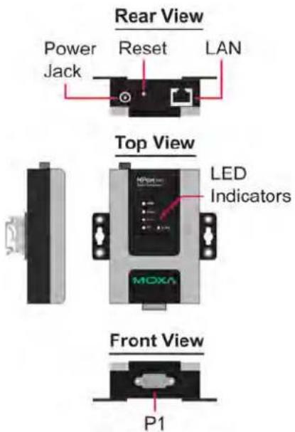
NPort 6250
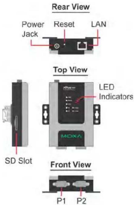
NPort 6450
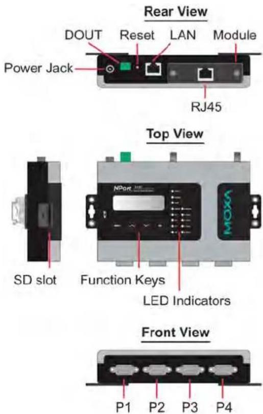
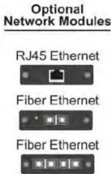
Note: The LCD panel is only available with standard temperature models.
NPort 6610/6650
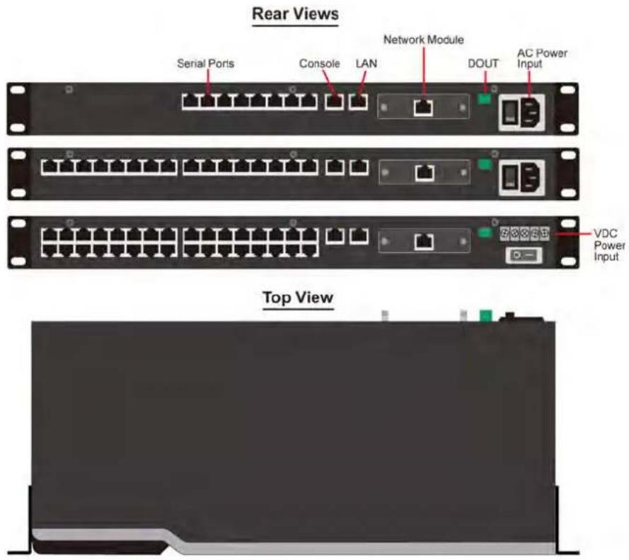
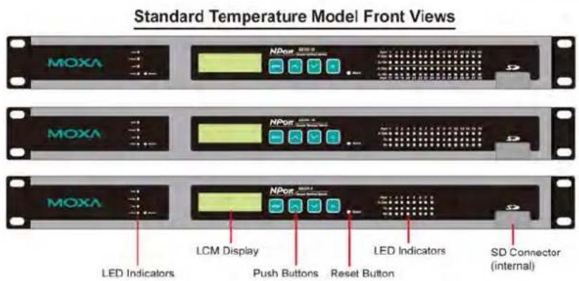
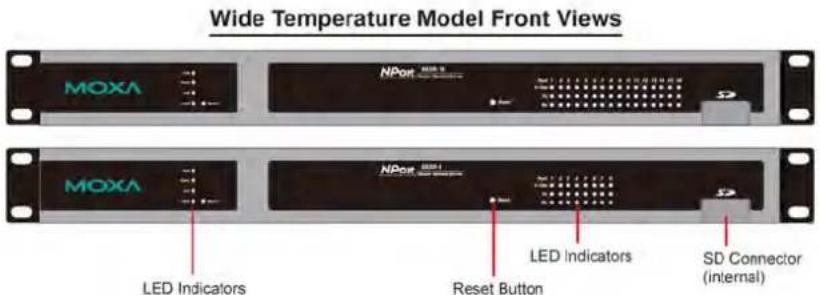
Panel, DIN-Rail, and Rack Mounting
Wall or Cabinet Mounting
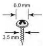
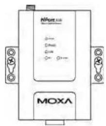
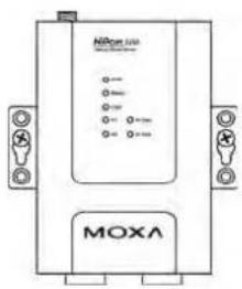
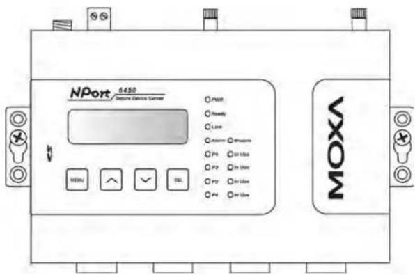
The NPort 6150, 6250, and 6450 device servers have built-in "ears" for attaching the device server to a wall or the inside of a cabinet. We suggest using two screws per ear to attach the device servers to a wall or the inside of a cabinet. The heads of the screws should be less than 6.0mm in diameter, and the shafts should be less than 3.5mm in diameter, as shown in the figure at the right.
NPort 6150
NPort 6250
NPort 6450
DIN-Rail Mounting
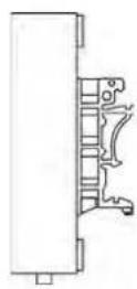
DIN-rail attachments can be purchased separately to attach the NPort 6150, 6250, and 6450 to a DIN-rail. When snapping the attachments to the DIN-rail, make sure that the stiff metal springs are at the top.
NPort 6150
NPort 6250
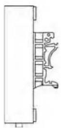
NPort 6450
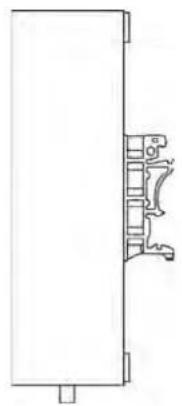
natural_image
Pure technical line drawing of a mechanical bracket or bracket (no text or symbols)Rack Mounting
Use four screws to attach the NPort 6610/6650 to a standard rack.
NPort 6610/6650

Connecting the Hardware
This section describes how to connect the NPort 6000 to serial devices for the first time.
Wiring Requirements

ATTENTION
Disconnect the power before installing and wiring
Disconnect the power cord before installing and/or wiring your NPort 6000.
Do not exceed the maximum current for the wiring
Determine the maximum possible current for each power wire and common wire. Observe all electrical codes dictating the maximum current allowable for each wire size.
If the current exceeds the maximum rating, the wiring could overheat, causing serious damage to your equipment.
Server may get hot; use caution when handling
Use caution when handling the NPort 6000 after it has been plugged in. The internal components generate heat, and the casing may get too hot to touch..
You should also heed the following guidelines:
- Use separate paths to route wiring for power and devices. If power-wiring and device-wiring paths must cross, make sure the wires are perpendicular at the intersection point.
NOTE: Do not run signal or communication wiring and power wiring in the same wire conduit. To avoid interference, wires with different signal characteristics should be routed separately. - The type of signal transmitted through a wire should determine which wires should be kept separate. The rule of thumb is that wires sharing similar electrical characteristics may be bundled together.
- Keep input wiring and output wiring separate.
- It is good practice to label the wiring to all devices in the system.
Connecting the NPort 6600 VDC's Power
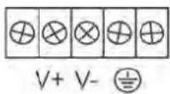
To connect the NPort 6600-32/16/8-48V's power cord with its terminal block, follow the steps given below:
-
Loosen the screws on the V+ and V- terminals of the NPort 6600 VDC's terminal block.
-
Connect the power cord's VDC wire to the terminal block's V+ terminal and the power cord's DC Power Ground wire to the terminal block's V- terminal; then, tighten the terminal block screws. (Note: The NPort 6600 VDC can still operate even if the DC and DC Power Ground are reversed.)
If the power is properly supplied, the "Ready" LED will glow solid red until the system is ready, at which time the "Ready" LED will change to green.
NOTE You should use 8 kg-cm of screw torque and 22-14 AWG of suitable electric wire to connect the NPort 6600 VDC's power cord to its terminal block.
Grounding the NPort 6600 VDC
Grounding and wire routing help limit the effects of noise due to electromagnetic interference (EMI). Run the ground connection from the ground screw to the grounding surface before connecting devices.
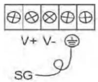
The Shielded Ground (sometimes called Protected Ground) contact is the second contact from the right of the 5-pin power terminal block connector located on the rear panel of the NPort 6600 VDC. Connect the SG wire to the earth ground.

ATTENTION
This product is intended to be mounted to a well-grounded mounting surface such as a metal panel.
Connecting to the Network
Connect one end of the Ethernet cable to the NPort 6000's 10/100M Ethernet port and the other end of the cable to the Ethernet network. If you are using a fiber-port version of the NPort 6000, connect the fiber cable from the Ethernet network to the NPort 6000's fiber port.
If the cable is properly connected, the NPort 6000 will indicate a valid connection to the Ethernet as follows:
• The Ethernet LED glows solid green when connected to a 100 Mbps Ethernet network.
- The Ethernet LED glows solid orange when connected to a 10 Mbps Ethernet network.
- The Ethernet LED flashes when Ethernet packets are being transmitted or received.
Connecting to a Serial Device
Connect the serial data cable between the NPort 6000 and the serial device. Serial data cables are available as optional accessories.
LED Indicators
The LED indicators on the front panel of the NPort 6000 are described in the following table.
| LED Name | LED Color | LED Function |
| PWR | Red | Power is being supplied to the power input. |
| Ready | Red | Steady on: Power is on, and the NPort 6000 is booting up.Blinking: An IP conflict occurs, or the DHCP or BOOTP server does not respond properly. |
| Green | Steady on: Power is on, and the NPort 6000 is functioning normally.Blinking: The device server has been located by NPort Search Utility. | |
| Off | Power is off, or there is a power error condition. | |
| Link | Orange | The NPort 6000 is connected to a 10-Mbps Ethernet connection. |
| Green | The NPort 6000 is connected to a 100-Mbps Ethernet connection. | |
| Off The Ethernet cable is disconnected or has a short. | ||
| P1 to P16 in-use LED | Green | The serial port is opened by server-side software. |
| Off | The serial port is not opened by server-side software. | |
| P1, P2, P3, P4(6150/6250/6450) | Orange | The serial port is receiving data. |
| Green The serial port is transmitting data. | ||
| Off | No data is being transmitted or received through the serial port. | |
| P1 to P16 Tx(6610/6650) | Green The serial port is transmitting data. | |
| Off Data is not being transmitted through the serial port. | ||
| P1 to P16 Rx(6610/6650) | Orange | The serial port is receiving data. |
| Off No data is | being received through the serial port. | |
The NPort 6450 and 6650 models have additional LEDs for the alarm and optional network modules:
| LED Name | LED Color | LED Function |
| Module(6450/6610/6650) | Green | The fiber-optic network module is plugged in and has been detected. |
| Off | The fiber-optic network module is not present. | |
| Link (on optional network modulesNM-FX01-M-SC,NM-FX01-S-SC) | Orange | Steady on: The NPort 6000 device server is connected to an Ethernet fiber connection, but the port is idle.Blinking: The fiber port is transmitting or receiving data. |
| Alarm(6450/6610/6650) | Red | The relay output (DOUT) is open (exception). |
| Off | The relay output (DOUT) is short (normal condition). |
Adjustable Pull High/ Low Resistors for the RS-485 Port
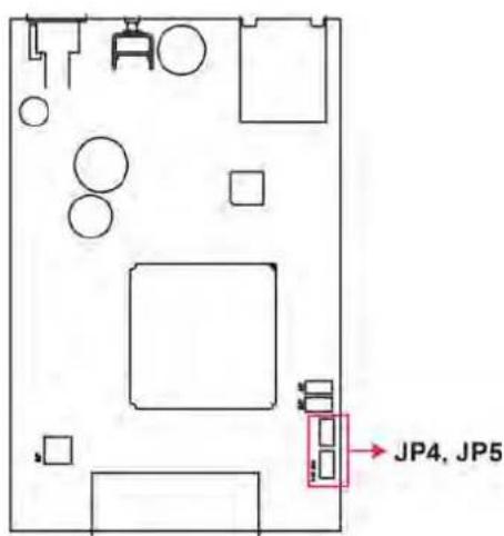
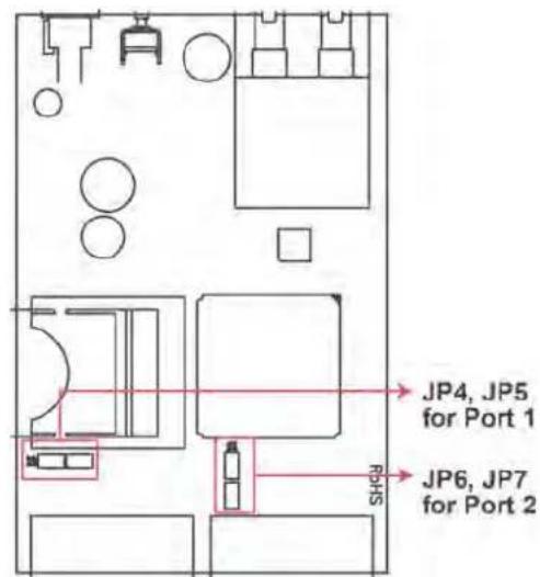
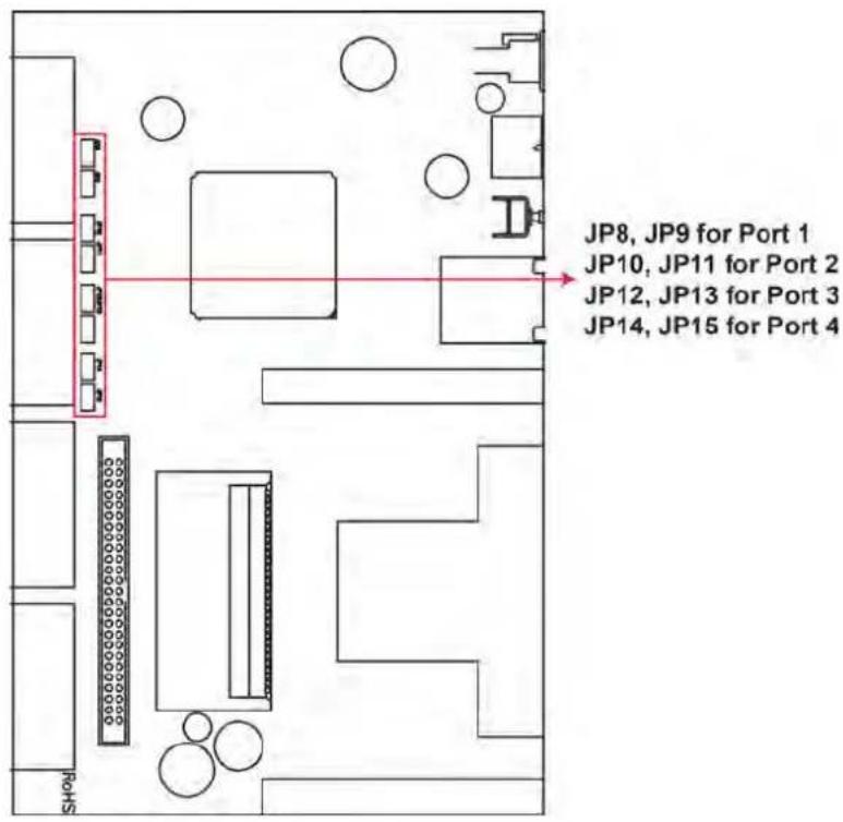
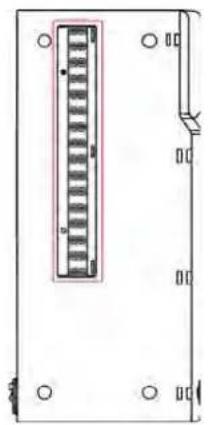
In some critical environments, you may need to add termination resistors to prevent the reflection of serial signals. When using termination resistors, it is important to set the pull high/low resistors correctly so that the electrical signal is not corrupted. The NPort 6000 uses jumper settings or DIP switches to set the pull high/low resistor values for each serial port.
To set the pull high/ low resistors to 150 KΩ, make sure that the two jumpers assigned to the serial port are not shorted by jumper caps. (For the NPort 6650, make sure both of the assigned DIP switches are in the OFF position.) This is the default setting.
To set the pull high/ low resistors to 1 KΩ, make sure that the two jumpers assigned to the serial port are shorted by jumper caps. (For the NPort 6650, make sure both of the assigned DIP switches are in the ON position.)

ATTENTION
Do not use the 1 KΩ setting on the NPort 6000 when using the RS-232 interface. Doing so will degrade the RS-232 signals, shorten the maximum allowed communication distance, and the Rx LED may light up.
NPort 6150/6250/6450 Jumpers
NPort 6150
NPort 6250
NPort 6450
NPort 6650 DIP Switches
natural_image
Pure electrical connector diagram without any text, numbers, or symbols| SW | 1 2 3 | ||
| Pull High Pull Low Terminator | |||
| ON | 1 KΩ | 1 KΩ | 120 KΩ |
| OFF | 150 KΩ | 150 KΩ | - |
When setting up the NPort 6000 for the first time, the first thing you should do is configure its IP address. This chapter introduces the different methods that can be used. Refer to Chapter 9, System Management Settings, for more details about network settings.
The following topics are covered in this chapter:
☐ Static and Dynamic IP Addresses
☐ Factory Default IP Address
□ Configuration Options
NPort Search Utility
Web Console
➢ LCM Console/Front Panel (NPort 6610, 6650, and 6450 only)
ARP
Telnet Console
Serial Console
Static and Dynamic IP Addresses
Determine whether your NPort 6000 needs to use a static IP or dynamic IP address (either DHCP or BOOTP/PPPoE application).
- If your NPort 6000 is used in a static IP environment, you will assign a specific IP address, using one of the tools described in this chapter.
- If your NPort 6000 is used in a dynamic IP environment, the IP address will be assigned automatically from over the network. In this case, set the IP configuration mode to DHCP, DHCP/BOOTP, BOOTP, or PPPoE.

ATTENTION
Consult your network administrator on how to reserve a fixed IP address for your NPort 6000 in the MAC-IP mapping table when using a DHCP Server or BOOTP Server. For most applications, you should assign a fixed IP address to your NPort 6000.
Factory Default IP Address
The NPort 6000 is configured with the following default private IP address:
192.168.127.254
Note that IP addresses that begin with "192.168" are referred to as private IP addresses. Devices configured with a private IP address are not directly accessible from a public network. For example, you would not be able to ping a device with a private IP address from an outside Internet connection. If your application requires sending data over a public network, such as the Internet, your NPort 6000 will need a valid public IP address, which can be leased from a local ISP.
Configuration Options
NPort Search Utility
You may configure your NPort 6000 with the bundled NPort Search Utility for Windows. Please refer to Chapter 10, Software Installation/Configuration, for details on how to install and use NPort Search Utility.
Web Console
You may configure your NPort 6000 using a standard web browser. Please refer to Chapter 5, Configuration with the Web Console, for details on how to access and use the NPort 6000 web console.
LCM Console/ Front Panel (NPort 6610, 6650, and 6450 only)
The NPort 6610, 6650, and 6450 only give you the option to configure some settings through the front panel, also known as the LCM (Liquid Crystal Module) console. The LCM console can be configured for read-only or writeable access. Read-only access allows settings to be viewed but not changed. Factory default settings are for writeable access, where configuration is allowed through the LCM console.

ATTENTION
If a password has been enabled for the NPort 6000 console and the LCM console is configured for writeable status, the LCM console will require you to enter the password before allowing you access. The password will not be required if the LCM console is configured for read-only access.
The MENU button activates the main menu. It is also used to cancel a selection and return to a previous menu.
The UP and DOWN buttons navigate between available options.
The SEL button confirms a selection or enters a submenu.
The IP environment (Static, DHCP, PPPoE, etc.) is configured under Main Menu → Network setting → IP config. The IP address is configured under Main Menu → Network setting → IP address. After the address has been entered, you will need to restart the NPort under Main Menu → Save/ Restart.
The following instructions explain how to set the NPort 6000's IP address through the LCM console:
- Press MENU to activate the Main Menu.
- The first line of the display indicates the current menu and should read Main Menu. The second line indicates the current selection and should read Server setting. Use the UP and DOWN buttons to select Network setting. Press SEL to enter the Network setting menu.
- In the Network setting menu, select IP config. Don't forget to press SEL to confirm your selection.
- In the IP config menu, use the UP and DOWN buttons to select the option that matches your IP environment (Static, DHCP, etc.). Press SEL to confirm your choice. You may also press MENU to cancel your selection and return to the previous submenu.
- You should be back in the Network setting menu. From the Network setting menu, select IP address.
- Use the UP and DOWN buttons to modify the digit currently selected by the blinking cursor. Press SEL to move to the next digit. Continue modifying the IP address until all the digits have been entered. If you make a mistake, press MENU to cancel all changes and return to the Network setting menu. You cannot go back one digit.
- Once you have finished modifying the IP address, your changes are saved but not in effect. In order for your changes to take effect, you will need to restart the NPort. You may view and modify your changes by selecting IP address at the Network setting menu again.
- Press the menu button to exit the Network setting menu and return to the Main Menu. Use the UP and DOWN buttons to select Save/ Restart and press SEL. Use the UP and DOWN buttons to select Yes and press SEL to restart.
NOTE Only standard temperature models come with an LCM console.
ARP
You may use the ARP (Address Resolution Protocol) command to set up an IP address for your NPort 6000. The ARP command tells your computer to associate the NPort 6000's MAC address with an IP address. Afterwards, use Telnet to access the NPort 6000, and its IP address will be reconfigured.

ATTENTION
In order to use the ARP setup method, both your computer and the NPort 6000 must be connected to the same LAN. Alternatively, you may use a crossover Ethernet cable to connect the NPort 6000 directly to your computer's Ethernet card. Before executing the ARP command, your NPort 6000 must be configured with the factory default IP address (192.168.127.254), and your computer and the NPort 6000 must be on the same subnet.
To use ARP to configure the IP address, complete the following:
- Obtain a valid IP address for your NPort 6000 from your network administrator.
- Obtain your NPort 6000's MAC address from the label on the bottom panel.
- Execute the arp s command from your computer's MS-DOS prompt as follows:
arp -s <IP address> <MAC address>
For example,
C:\> arp -s 192.168.200.100 00-90-E8-04-00-11
- Next, execute a special Telnet command by entering the following exactly:
telnet 192.168.200.100 6000
When you enter this command, a "Connect failed" message will appear, as shown below.

- After the NPort 6000 reboots, its IP address will be assigned to the new address, and you can reconnect using Telnet to verify that the update was successful.
Telnet Console
Depending on how your computer and network are configured, you may find it convenient to use network access to set up your NPort 6000's IP address. This can be done using Telnet.

ATTENTION
Figures in this section were taken from the NPort 6650's Telnet console.
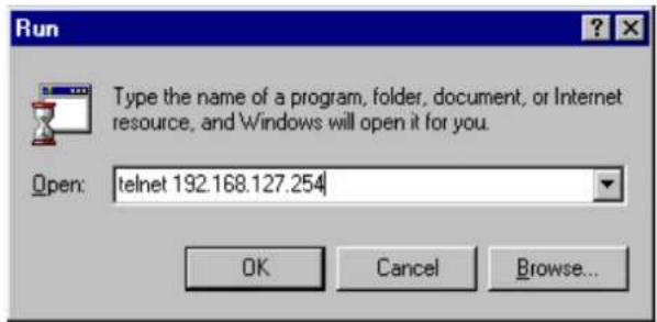
- From the Windows desktop, select Start Run and type the following in the Run window: telnet 192.168.127.254
If your IP address is different from the default setting, use your IP address instead. Click OK.
- The console terminal type selection is displayed as shown. Enter 1 for ansi/ vt100 and press ENTER to continue.

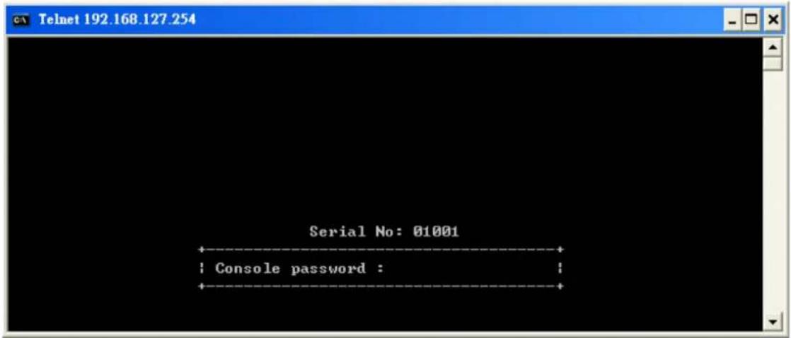
- The following page will only appear if the NPort 6000 is password protected. Enter the console password if you are prompted to do so, and press ENTER.
- Press N or use the arrow keys to select Network and then press ENTER.
![Telnet 192.168.127.254 NP6650-16 NP6650-16_1 1.0 (Jun 28 2006 - 13:04:40) MAIN MENU Overview Basic [Network] Port System Monitor sAve Restart Exit Examine/modify the ethernet LAN port settings Enter: select ESC: previous menu](/content/2026/06/1269850/images/262969a6567a8d91e08c1652173231fcd88a733544d33a747945d7ae6acc9812.jpg)
- Press B or use the arrow keys to select Basic and then press ENTER.
![Telnet 192.168.127.254 NP6650-16 NP6650-16_1 1.0 (Jun 28 2006 - 13:04:40) NETWORK MENU [Basic] Advanced Quit Examine/modify basic network settings Enter: select ESC: previous menu](/content/2026/06/1269850/images/1cdc2658445069b240f73457df2c5a52d37ee69a3de37075cfaf0b241106364b.jpg)
- Use the arrow keys to move the cursor to IP address. Use the DELETE, BACKSPACE, or SPACE keys to erase the current IP address; then, type in the new IP address and press ENTER. Note that if you are using a dynamic IP configuration (BOOTP, SHCP, etc.), you will need to go to the IP configuration field and press ENTER to select the appropriate configuration.
![Telnet 192.168.127.254 NP6650-16 NP6650-16_1 1.0 (Jun 28 2006 - 13:04:40) [Basic] Advanced Quit Examine/modify basic network settings ESC: back to menu Enter: select IP configuration [Static ] IP address [192.168.1 ] Netmask [255.255.255.0 ] Gateway [ ] DNS server 1 [ ] DNS server 2 [ ] PPPoE user account [ ] PPPoE password [ ] WINS function [Enable ] WINS server [ ] LAN1 speed [Auto ]](/content/2026/06/1269850/images/26a7f626511e8572dfdf6b9804d5b6465305f5cdac57efd7d0806693e13f5148.jpg)
- Press ESC twice to return to previous page. Press Y to confirm the modification.
![[Basic] Advanced Quit Examine/modify basic network settings Enter: select ESC: previous menu Warning !!! You have modified the configuration without saving. Would you save it now ? 'Y: yes 'N': no_](/content/2026/06/1269850/images/4a2975166bcad8a64e986c451eaa12ce174b9d9e36d53f87423117ae4e770807.jpg)
- Press ESC to return to previous page.
- Press A or use the arrow keys to select Save and then press ENTER. Press ENTER again to confirm the save command.
![Telnet 192.168.127.254 NP6650-16 NP6650-16_1 1.0 (Jun 28 2006 - 13:04:40) Overview Basic Network Port System Monitor [SAVE] Restart Exit Save current configuration to flash ROM ESC: back to menu Enter: select Enter to update, other key to cancel!](/content/2026/06/1269850/images/4e3bbd31df2c281ac8942556acaf7be24ec6845d51ff90875516d673c0382de1.jpg)
- Press R or use the arrow keys to select Restart and then press ENTER.
![Telnet 192.168.127.254 NP6650-16 MP6650-16_1 1.0 (Jun 28 2006 - 13:04:40) MAIN MENU Overview Basic Network Port System Monitor sAve [Restart] Exit Restart the whole system or selected serial ports Enter: select ESC: previous menu](/content/2026/06/1269850/images/b0a15791d67880235d5227dd5b8260b46bcc973f965605d2c054bd17ae48c849.jpg)
- Press S or use the arrow keys to select System ;then press ENTER to restart the NPort 6000.
![[System] Port Quit Restart the server ESC: back to menu Enter: select Warning !!! Restart system will disconnect all ports and clear all status value Enter: continue ESC: cancel](/content/2026/06/1269850/images/9ccb99be3d2d2f788b1e43d24b96803e00414456dbeee17c386af23e4edc28cc.jpg)
Serial Console
The NPort 6000 supports configuration through the serial console, which is the same as the Telnet console but accessed through the RS-232 console port rather than through the network. Once you have entered the serial console, the configuration options and instructions are the same as if you were using the Telnet console.
The following instructions and screenshots show how to enter the serial console using PComm Terminal Emulator, which is available free of charge as part of the PComm Lite suite. You may use a different terminal emulator utility, although your actual screens and procedures may vary slightly from the following instructions.
- Turn off the power to the NPort 6000. Use a serial cable to connect the NPort 6000's serial console port to your computer's male RS-232 serial port.

ATTENTION
The NPort 6610/ 6650 has a dedicated serial console port. For the PIN definition, see the RS -232 PINOUT on Page A-2 under the following heading: NPort 6600: RS-232/422/485 (male RJ45). For all other NPort 6000 models, port 1 serves as the serial console port.
- From the Windows desktop, select Start → All Programs → PComm Lite → Terminal Emulator.
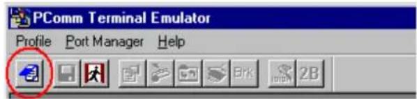
- The PComm Terminal Emulator window should appear. From the Port Manager menu, select Open, or simply click the Open icon as shown below:
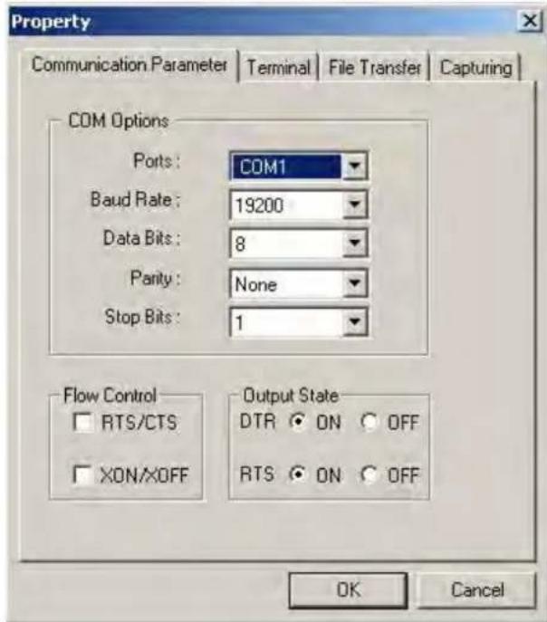
- The Property window opens automatically. Select the Communication Parameter tab; then, select the appropriate COM port for the connection (COM1 in this example). Configure the parameters for 19200, 8, N, 1 (19200 for Baudrate, 8 for Data Bits, None for Parity, and 1 for Stop Bits).
- From the Property window's Terminal page, select ANSI or VT100 for Terminal Type and click OK.
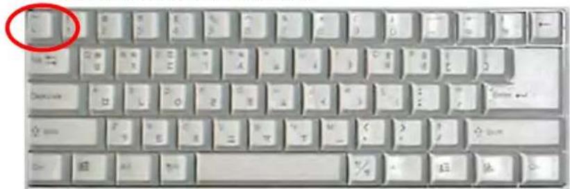
- If you are using the NPort 6610/6650, you may power it up at this point. If you are using the NPort 6150, 6250, or 6450, hold down the "grave accent" key (') while powering it up, as shown below. Note that the "grave accent" key (sometimes called "backwards apostrophe") is NOT the apostrophe key—it is the key usually found next to the number 1 key.
The NPort 6000 will then automatically switch from data mode to console mode.
- If the NPort 6000 has been set up for password protection, you will be prompted to enter the password. After you entered the password, or if password protection was not enabled, you will be prompted to select the terminal mode. Press 1 for ansi/ vt100 and then press ENTER.
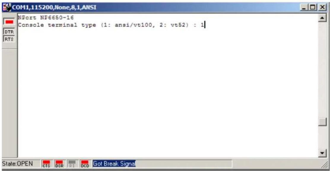
- The main menu should come up. Once you are in the console, you may configure the IP address through the Network menu item, just as with the Telnet console. Please refer to steps 4 to 11 in the Telnet Console section to complete the initial IP configuration.
![COM1,19200,None,8,1,ANSI NP6650-16 NP6650-16_1 1.0 (Jun 28 2006 - 13:04:40) MAIN MENU Overview Basic [Network] Port System Monitor sAve Restart Exit Examine/modify the ethernet LAN port settings Enter: select ESC: previous menu](/content/2026/06/1269850/images/b127037b04320ebe98682019e531535dd4b73c04d96972dd86efd1fa4dfd5541.jpg)
In this chapter, we describe the various operation modes of the NPort 6000. NPort 6000 modes are grouped by type of application, such as Device Control or Reverse Terminal. The options include an operation mode that relies on a driver installed on the host computer and operation modes that rely on TCP/IP socket programming concepts. After selecting the proper operation mode, refer to Chapter 5, Configuration with the Web Console, for detailed information on configuration parameters.
The following topics are covered in this chapter:
Overview
☐ Guide to NPort 6000 Modes
□ Device-Control Applications
Real COM and Secure Real COM Modes
➢ Reverse Real COM Mode
RFC2217 Mode
□ Socket Applications
TCP Server and Secure TCP Server Modes
TCP Client and Secure TCP Client Modes
▶ UDP Mode
☐ Pair Connection and Secure Pair Connection Modes
□ Ethernet Modem Mode
□ Terminal Applications
Terminal ASCII Mode
Terminal BIN Mode
SSH Mode
☐ Reverse Terminal Applications
Reverse Telnet
Reverse SSH
□ Printer Modes
□ Dial In/ Out Modes
□ Disabled Mode
Overview
The NPort 6000 network enables traditional serial (RS-232/422/485) devices. The serial device server is a tiny computer equipped with a CPU and TCP/IP protocols that can bi-directionally translate data between the serial and Ethernet formats. Your computer can access, manage, and configure remote facilities and equipment over the Internet from anywhere in the world.
Traditional SCADA and data collection systems rely on serial ports to collect data from various kinds of instruments. Since the NPort 6000 network-enables instruments equipped with an RS-232, RS-422, or RS-485 communication port, your SCADA and data collection system will be able to access all instruments connected to a standard TCP/IP network, regardless of whether the devices are used locally or at a remote site.
The NPort 6000 is an external IP-based network device that allows you to expand the number of serial ports for a host computer on demand. As long as your host computer supports the TCP/IP protocol, you will not be limited by the host computer's bus limitation (such as ISA or PCI), nor will you be limited by the absence of drivers for various operating systems.
In addition to providing socket access, the NPort 6000 also comes with a Real COM/TTY driver that transmits all serial signals intact. This enables you to preserve your existing COM/TTY-based software without needing to invest in additional software.
Three different socket modes are available: TCP Server, TCP Client, and UDP Server/Client. The main difference between the TCP and UDP protocols is that TCP guarantees delivery of data by requiring the recipient to send an acknowledgement to the sender. UDP does not require this type of verification, making it possible to offer faster delivery. UDP also allows unicast or multi-unicast of data to one IP or groups of IP addresses.
The NPort 6000 also supports console management applications, including Reverse Telnet, as well as Reverse SSH terminal modes. Reverse terminal modes enable you to connect to a server's console port through an IP network for remote control and/or monitoring of that server.
The NPort 6000 supports standard SSL secure data access for Real COM/TTY mode, TCP server mode, TCP Client mode, and Pair Connection mode. Data transmitted on the Ethernet will be well protected.
Guide to NPort 6000 Modes
On the NPort 6000, each serial port is independently configurable for a different mode with different settings. For example, on the NPort 6450, an administrator can easily configure two ports for Real COM mode, one port for Ethernet Modem mode, and one port for Reverse Telnet mode. Please refer to Chapter 7, Configuring Serial Port Operation Modes, for detailed information and configuration instructions.
Device-Control Applications
For device-control applications, the NPort 6000 offers the following modes: Real COM/Secure Real COM mode and RFC2217 mode.
Real COM and Secure Real COM Modes
flowchart
graph TD
    A["COM3 = IP Port"] --> B["TCP/IP Ethernet"]
    B --> C["Driver Mode"]
    C --> D["RS-232/422/485"]
    C --> E["Device"]
The NPort 6000 comes bundled with Real COM drivers for Windows systems and TTY drivers for Linux systems. Real COM mode includes optional data encryption, using SSL.
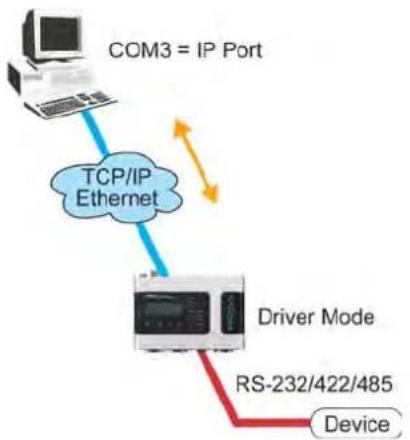
In Real COM mode, the bundled drivers are able to establish a transparent connection between a host and a serial device by mapping the serial port on the NPort 6000 to a local COM/TTY port on the host computer. Real COM mode supports up to 8 simultaneous connections that enable multiple hosts to simultaneously collect data from the same serial device.
One of the major conveniences of using Real COM mode is that it allows you to use software that was written for pure serial communication applications. The Real COM driver intercepts data sent to the host's COM port, packs it into a TCP/IP packet, then redirects it through the host's Ethernet card. At the other end of the connection, the NPort 6000 accepts the Ethernet frame, unpacks the TCP/IP packet, and then transparently sends the data through the serial port to the attached serial device.

ATTENTION
Real COM mode allows several hosts to have access control over the same NPort 6000. The drivers that come with your NPort 6000 control host access by checking the host's IP address. Please refer to the Accessible IP List section in Chapter 9, System Management Settings, for more details.
Reverse Real COM Mode
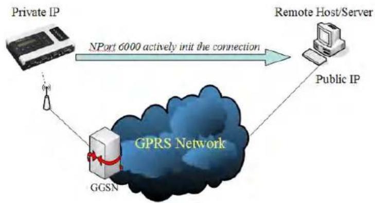
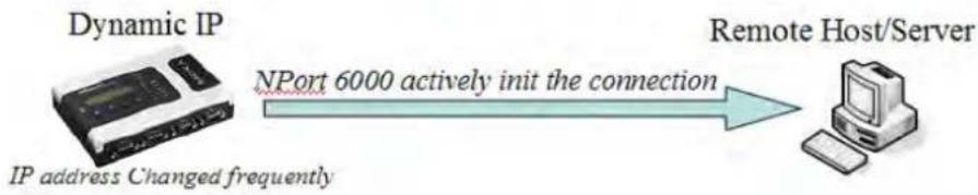
Real COM mode will not work when the NPort 6000 is using a private IP address, or if the NPort 6000 is in a dynamic IP address environment. In either of these cases, the remote host/server will not be able to connect to the NPort 6000.
Private IP address application
flowchart
graph TD
    A["Private IP"] -->|NPort 6000 actively init the connection| B["Remote Host/Server"]
    B --> C["Public IP"]
    C --> D["GPRS Network"]
    D --> E["GGSN"]
    E --> F["Wireless Tower"]
Dynamic IP address application
flowchart
graph LR
    A["Dynamic IP"] -->|NPort 6000 actively init the connection| B["Remote Host/Server"]
    A -->|IP address Changed frequently| B
Reserve Real COM mode is an innovative operation mode developed by Moxa. It allows NPort 6000 terminal servers to achieve the same effect as Real COM mode, but without needing to apply for a public IP address. In other words, Reverse Real COM mode can be used even if the NPort is using a private IP address, or is being used in a dynamic IP address environment.
In Reserve Real COM mode, the NPort 6000 will actively initiate a connection to the remote host/server that is listed in the destination IP field after it boots up.
RFC2217 Mode
RFC-2217 mode is similar to Real COM mode. That is, a driver is used to establish a transparent connection between a host computer and a serial device by mapping the serial port on the NPort 6000 to a local COM port on the host computer. RFC2217 defines general COM port control options based on the Telnet protocol. Third-party drivers supporting RFC-2217 are widely available on the Internet and can be used to implement Virtual COM mapping to your NPort 6000 serial port(s).
Socket Applications
For socket applications, the NPort 6000 offers the following modes: TCP Server/Secure TCP Server, TCP Client/Secure TCP Client, and UDP.
TCP Server and Secure TCP Server Modes
flowchart
graph TD
    A["Computer"] -->|① Request a connection| B["TCP Server"]
    B -->|② Proceed with data transmission| A
    B -->|① TCP/IP Ethernet| C["Device"]
    B -->|②| D["RS-232/422/485"]
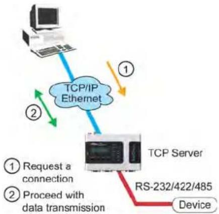
In TCP Server mode, the serial port on the NPort 6000 is assigned a port number which must not conflict with any other serial port on the NPort 6000. The host computer initiates contact with the NPort 6000, establishes the connection, and receives data from the serial device. This operation mode also supports up to 8 simultaneous connections, enabling multiple hosts to collect data from the same serial device at the same time.
As illustrated in the figure, data transmission proceeds as follows:
- The host requests a connection from the NPort 6000, which is configured for TCP Server mode.
- Once the connection is established, data can be transmitted in both directions between the host and the NPort 6000.
TCP Server mode supports optional data encryption using SSL.
TCP Client and Secure TCP Client Modes
flowchart
graph TD
    A["Computer"] -->|① Request a connection| B["TCP/IP Ethernet"]
    B -->|② Proceeds with data transmission| C["TCP Client"]
    C -->|③ Device| D["RS-232/422/485"]
    B -->|④ Data transmission| C
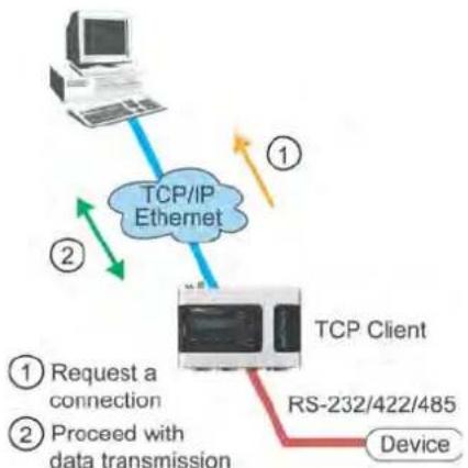
In TCP Client mode, the NPort 6000 can actively establish a TCP connection to a pre-defined host computer when serial data arrives. After the data has been transferred, the NPort 6000 can automatically disconnect from the host computer by using the Inactivity time settings.
As illustrated in the figure, data transmission proceeds as follows:
- The NPort 6000, configured for TCP Client mode, requests a connection from the host.
- Once the connection is established, data can be transmitted in both directions between the host and the NPort 6000.
TCP Client mode includes optional data encryption using SSL.
UDP Mode
flowchart
graph TD
    A["Computer"] --> B["UDP Ethernet"]
    B --> C["RS-232/422/485 Device"]
    B -->|Directly proceed with data transmission (no connection required)| D["User Interface"]
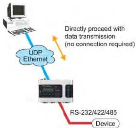
Compared to TCP communication, UDP is faster and more efficient. In UDP mode, you can unicast or multi-unicast data from a serial device to one or multiple host computers; and the serial device can receive data from one or multiple host computers. These traits make UDP mode especially suited for message display applications.
Pair Connection and Secure Pair Connection Modes
flowchart
graph TD
    A["Device"] --> B["NPort 6000 Series "Slave""]
    B --> C["TCP/IP Ethernet"]
    C --> D["NPort 6000 Series "Master""]
    D --> E["Device"]
    B --> F["RS-232/422/485"]
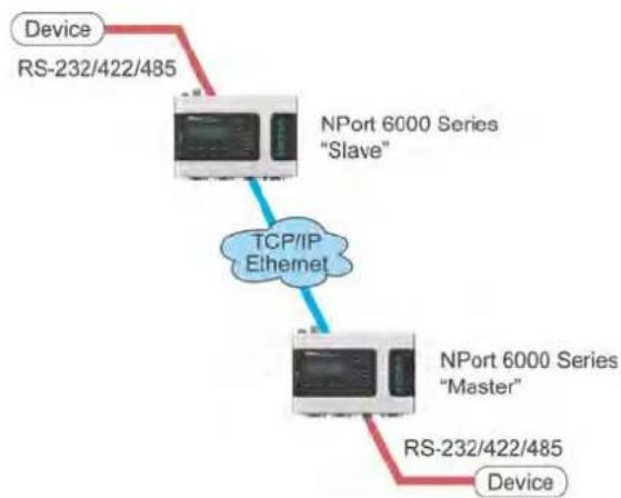
In Pair Connection mode, two NPort 6000 servers work together to remove the 15-meter distance limitation imposed by the RS-232 interface. One server is arbitrarily designated the "master" and the other as the "slave"—it does not matter which is which as long as there is one of each. One server is connected from its RS-232 port to the COM port of a PC or another type of computer, such as a handheld PDA that has a serial port; the other server is connected to the serial device through its RS-232 port.
The two servers are then connected to each other over the network.
Ethernet Modem Mode
flowchart
graph TD
    PC["PC"] --> RS232422485["RS-232/422/485"]
    RS232422485 --> EthernetModem["Ethernet Modem"]
    EthernetModem --> TCPIP1["Ethernet"]
    TCPIP1 --> EthernetModem1["Ethernet Modem"]
    EthernetModem1 --> Device["Device"]
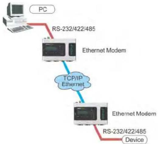
Ethernet Modem mode is designed for use with legacy operating systems, such as MS-DOS, that do not support TCP/IP Ethernet. By connecting the properly configured NPort 6000 serial port to the MS-DOS computer's serial port, it is possible to use legacy software to transmit data over the Ethernet if the software is originally designed to transmit data over a modem.
Terminal Applications
flowchart
graph TD
    A["Unix"] -->|TCP/IP| B["NPort 6000 Series"]
    C["Windows NT"] -->|TCP/IP| B
    B --> D["RS-232"]
    B --> E["Terminal"]
    B --> F["Terminal"]
    B --> G["Terminal"]
    style B fill:#f9f9f9,stroke:#333
    style D stroke:#ff0000,stroke-width:2px
    style E stroke:#ff0000,stroke-width:2px
    style F stroke:#ff0000,stroke-width:2px
    style G stroke:#ff0000,stroke-width:2px
    subgraph Telnet/SSH
        H["Termit"]
        I["Terminal"]
        J["Terminal"]
        K["Terminal"]
    end
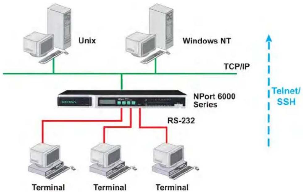
Terminal applications involve connecting terminals to UNIX or Windows servers over a network. A terminal connects to the appropriately configured serial port the NPort 6000, and the NPort 6000 transmits information to and from a UNIX or Windows server over the network through its Ethernet port. You may need to check with your network administrator to determine the appropriate terminal mode. All terminal modes support fast keys as used in many terminal applications.
Please refer to Chapter 4, Introducing Serial Port Operation Modes, for detailed information and configuration instructions.
Terminal ASCII Mode
Terminal ASCII mode can handle up to 8 sessions per port with the ability to switch between sessions on the same terminal. This mode is used for text-based terminals with no file transfer capability or encryption.
Terminal BIN Mode
Terminal BIN mode allows one session per port and is used for terminal applications that include file transfer features.
SSH Mode
SSH mode allows one session per port and is used for secure terminal applications that abide by the SSH protocol.
Reverse Terminal Applications
flowchart
graph TD
    A["Unix"] -->|TCP/IP| B["NPort 6000 Series"]
    C["Windows NT"] -->|TCP/IP| B
    D["Router"] -->|Telnet| B
    E["Server"] -->|RS-232| B
    F["Server"] -->|RS-232| B
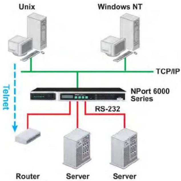
Reverse terminal applications are similar to terminal applications in that they involve using the NPort 6000 to manage the connection between a terminal and a server. The difference is that with reverse terminal applications, the terminal is connected through the network and the server is connected through the serial port, rather than the other way around. In practice, a reverse terminal session typically involves a network administrator telnetting to a device that has a dedicated serial console port used specifically for configuration purposes.
For example, many routers, switches, UPS units, and other devices (including the NPort 6000) have Console/AUX or COM ports to which a terminal can be physically connected for console management. With the NPort 6000, the device's console port can be connected to a serial port on the NPort 6000, allowing a network administrator to telnet to the device remotely through the network. Although modern network equipment generally allows other options for remote configuration through the network, there are situations in which it is necessary or desirable to configure a device by serial console (e.g., for security reasons, when using older-generation equipment, or as a backup configuration method when the network is down).
NPort 6000 reverse terminal modes allow the use of the NPort 6000 User Table or a RADIUS server for identity verification purposes. Please refer to the Misc. Network Settings section in Chapter 9, System Management Settings, for instructions on setting up the NPort 6000 User Table.
Reverse Telnet
Reverse Telnet mode is widely used for device management in control rooms. The system waits for a host on the network to initiate a connection. Since TCP Server mode does not assist with conversion of CR/LF commands, reverse terminal applications that require this conversion should use Reverse Telnet mode.
Reverse SSH
The NPort 6000 also offers a Reverse SSH mode so you can use SSH utilities such as PuTTY to connect to remote servers.
Printer Modes
flowchart
graph TD
    A["Unix"] -->|TCP/IP| B["NPort 6000 Series"]
    C["IBM"] -->|TCP/IP| B
    B --> D["RS-232"]
    B --> E["Printer"]
    B --> F["Printer"]
    B --> G["Printer"]
    B --> H["Printer"]
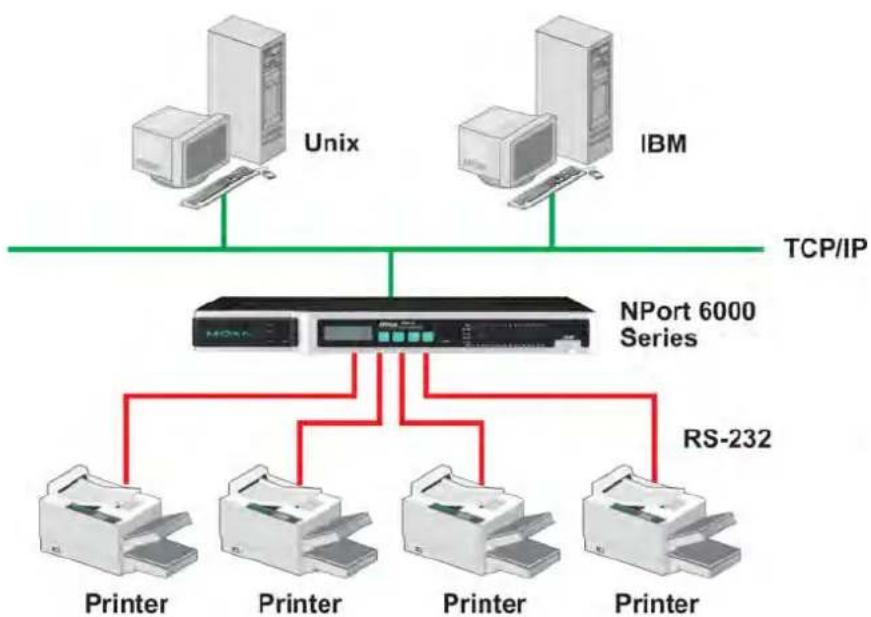
The NPort 6000's Printer mode provides an excellent solution for banking and stock exchange services with huge printing demands. Printer modes involve a network printer that is connected to a serial port on the NPort 6000, with a port number assigned to specify the printer's location. Windows or UNIX hosts can access the printer over the network in either RAW or LPD modes.
Please refer to Chapter 7, Configuring Serial Port Operation Modes, for detailed information and configuration instructions.
Dial In/ Out Modes
flowchart
graph TD
    A["Web Server"] --> B["NPort 6000 Series"]
    C["E-mail Server"] --> B
    B --> D["Router"]
    B --> E["Internet"]
    B --> F["Modem"]
    B --> G["Modem"]
    B --> H["UNIX Server"]
    B --> I["PC"]
    B --> J["Notebook"]
    B --> K["PPP Dialout"]
    B --> L["SLIP Dialin"]
    B --> M["PPP Dialin"]
    B --> N["Web Server"]
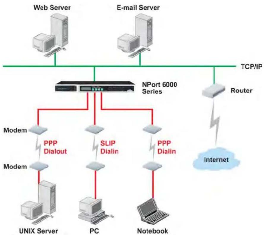
The NPort 6000 provides dial-in/dial-out access for ISPs and enterprises that need a remote access solution. When a user at a remote site uses a PPP dial-up connection to access the NPort 6000, the NPort 6000 plays the role of a dial-up server, but also ensures that the user has legal access to the network by verifying the user's identity with the NPort 6000 User Table or a RADIUS server. Please refer to the Misc. Network Settings section in Chapter 9, System Management Settings, for instructions on setting up the NPort 6000 User Table.
The NPort 6000 supports PPP, SLIP, and Terminal modes for dial-in/dial-out access. Regardless of which operating system is used, you will always be able to use standard PPP dial-up to establish a connection. The NPort 6000 can also act as a router to connect serial ports to a WAN connection. Routing protocols (including static, RIP I, and RIP II) can be adjusted to route different WAN connections.
Please refer to Chapter 5, Configuration with the Web Console, for detailed information and configuration instructions.
Disabled Mode
You can disable any port on the NPort 6000 by setting the operation mode to Disabled.
The web console is the most user-friendly method available to configure the NPort 6000. With a standard web browser, you have easy and intuitive access to all settings and options. In this chapter, we introduce the web console and go through the basic configuration options. The same configuration options are also available through the Telnet and serial console.
The following topics are covered in this chapter:
□ Using Your Web Browser
Browser Cookie Settings
Trusted Site Settings
Opening the Web Console
□ Web Console Navigation
□ Basic Settings
Server Settings
Time Settings
□ Network Settings
Basic Network Settings
▶ Advanced Network Settings
- Configuring the Route Table
Using Your Web Browser
Browser Cookie Settings
Verify that cookies are enabled for your browser. If the cookies are disabled, you will not be able to use the web console. (Cookies are only used for password transmission.)
- For Internet Explorer, enable cookies by selecting Internet Options from the Tools menu:
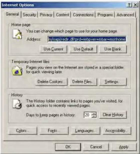
- Select the Privacy tab. There are six levels of privacy setting: Block All Cookies, High, Medium High, Medium, Low, and Accept All Cookies. Users must select Medium High (as the image shows below) to access the NPort 6000 web console.
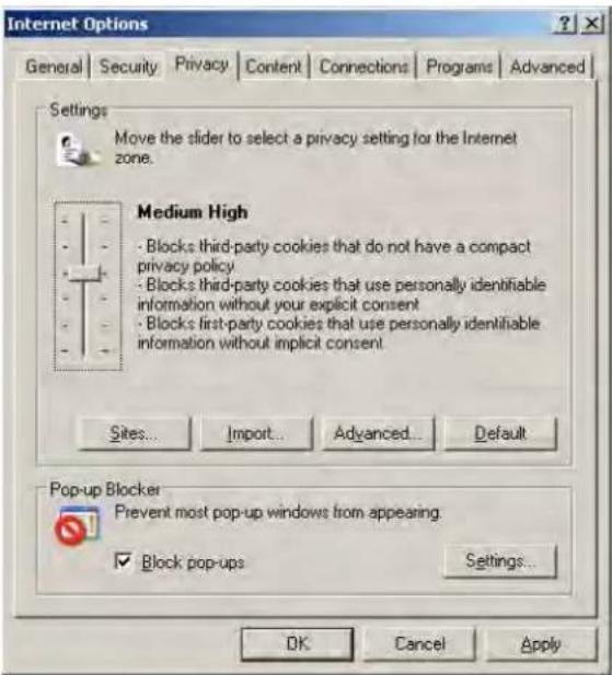

ATTENTION
If you are not using Internet Explorer, cookies are usually enabled through a web browser setting such as "allow cookies that are stored on your computer" or "allow per-session cookies."
Trusted Site Settings
For Windows 2003 users, you may need to add the NPort 6000's IP address to your browser's list of trusted sites.
- If you see the following window while attempting to view the web console, click on Add... to modify the list of trusted sites:
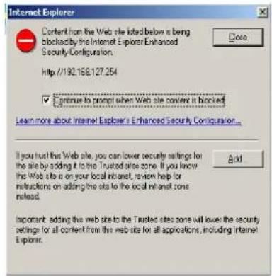
You may also directly access the list of trusted sites through Internet Options in the Tools menu of Internet Explorer. Select the Security tab, then click on the Trusted Sites icon and on the Sites... button:
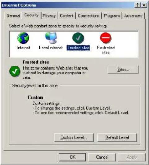
- In either case, the window below should appear, showing the list of sites that you have configured Internet Explorer to trust. Add the IP address of your NPort 6000 here (the factory default IP address is 192.168.127.254).
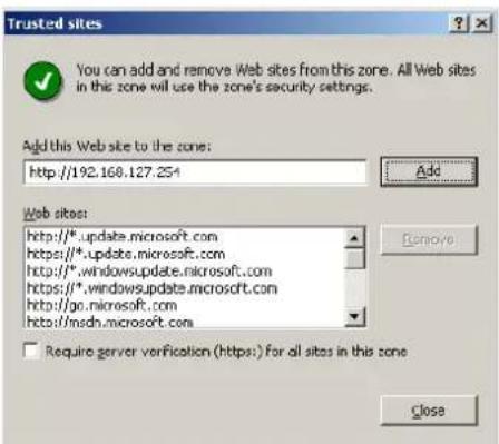
After adding the NPort 6000's IP address as a trusted site, you should be able to view the web console by entering the NPort 6000's IP address in your browser's address bar.
Opening the Web Console
Open your web browser and enter 192.168.127.254 in the website address line. This is the default IP address for the NPort 6000-if a new address has been assigned, enter the new address instead. Press ENTER to load the page.

ATTENTION
The examples and figures in this chapter use the NPort 6000 factory default IP address of 192.168.127.254. If you have assigned a different IP address to your NPort 6000, be sure to adjust accordingly when following these directions. Please refer to Chapter 3, Initial IP Address Configuration, for details on how to configure the IP address.
The default login username is admin with no password. Note that only the user admin can upgrade the firmware.
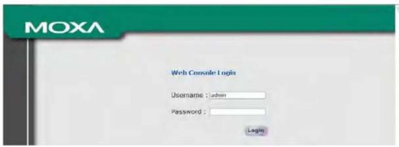

ATTENTION
If you forget your password, the ONLY way to configure the NPort 6000 is by using the reset button to reset all settings and load the factory defaults. If you have disabled the reset button in your NPort 6000 configuration, you may still use it to load the factory defaults within the first 60 seconds that the NPort 6000 is powered on.
Remember to back up your configuration by exporting it to a file. Your configuration can be easily restored by importing the file to the NPort 6000. This will save time if you have forgotten the password and need to reload the factory defaults.
The NPort 6000's web console will appear.
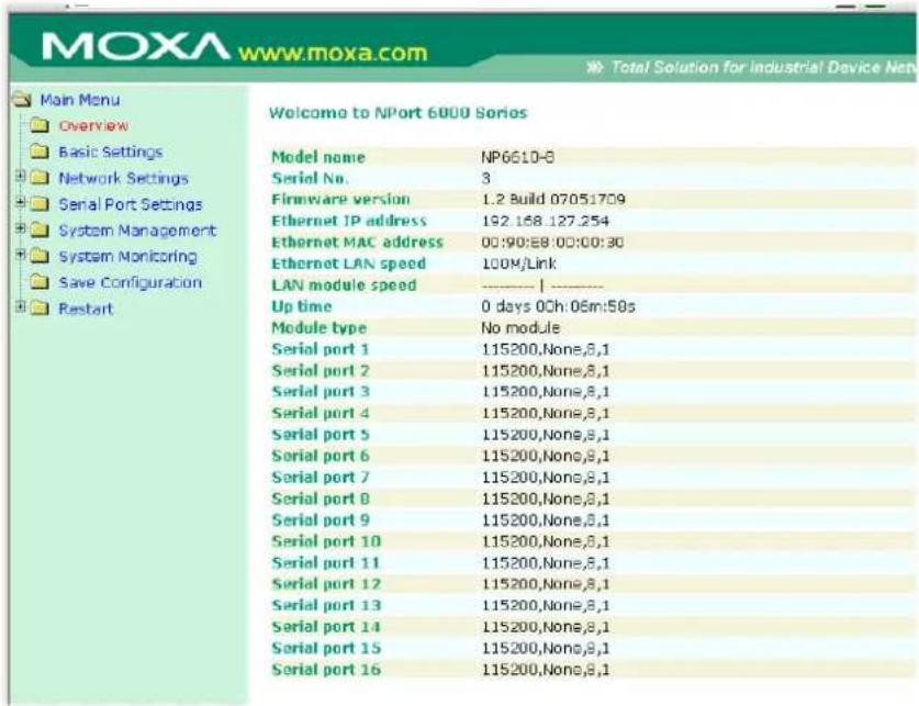
Web Console Navigation
On the NPort 6000 web console, the left panel is the navigation panel and contains an expandable menu tree for navigating among the various settings and categories. When you click on a menu item in the navigation panel, the main window will display the corresponding options for that item. Configuration changes can then be made in the main window. For example, if you click on Basic Settings in the navigation panel, the main window will show a page of basic settings that you can configure.
You must click on the Submit button to keep your configuration changes. The Submit button will be located at the bottom of every page that has configurable settings. If you navigate to another page without clicking the Submit button, your settings will not be retained.
Changes will not take effect until they are saved and the NPort is restarted! You may complete this in one step by clicking on the Save/ Restart option after you submit a change. If you need to make several changes before restarting, you may save your changes without restarting by selecting Save Configuration in the navigation panel. If you restart the NPort 6000 without saving your configuration, the NPort 6000 will discard all submitted changes.
Basic Settings
You may access Basic Settings in the navigation panel.
Server Settings
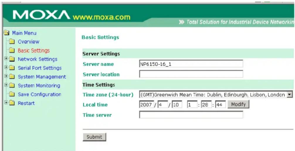
Server name: This is an optional free text field for your own use; it does not affect operation of the NPort 6000. It can be used to help differentiate one NPort 6000 server from another.
Server location: This is an optional free text field for your own use; it does not affect operation of the NPort 6000. It is useful for assigning or describing the location of a NPort 6000. In a network environment of multiple servers, this can be a valuable aid when performing maintenance.
Time Settings
The NPort 6000 has a built-in Real-Time Clock for time calibration functions. Functions such as Auto Warning Email or SNMP Trap can add real-time information to messages.
Before making any adjustments to the time, first select the correct time zone and submit the change. The console will display the real time according to the time zone. To modify the real-time clock, click on Modify next to the Local time field. Once you submit the new time, the NPort 6000's firmware will modify the GMT time according to your time zone and local time settings.

ATTENTION
A risk of an explosion exists if the real-time clock battery is replaced with the wrong type!
The NPort 6000's real time clock is powered by a lithium battery. We strongly recommend that you do not attempt replacement of the lithium battery without help from a qualified Moxa support engineer. If you need to change the battery, please contact the Moxa RMA service team.
Time zone (default=GMT Greenwich Mean Time): This field shows the currently selected time zone and allows you to select a different time zone.
Local time: This field shows the time that you last opened or refreshed the browser. To set the local time for the NPort 6000, click on the Modify... button, then submit your changes in the screen as shown below.
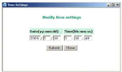
Time server: The NPort 6000 uses SNTP (RFC-1769) for auto time calibration. You may enter a time server IP address or domain name in this optional field. Once the NPort 6000 is configured with the correct time server address, it will request time information from the time server every 10 minutes.
Network Settings
Basic Network Settings
Network Settings - Basic
IPv4 Configuration
IPv4 configuration
IPv4 address
Netmask
Gateway
IPv4 DNS server 1
IPv4 DNS server 2
PPPoE user account
PPPoE password
WINS function
WINS server
IPv6 Configuration
IPv6 configuration
IPv6 address
Prefix
IPv6 Gateway
IPv6 DNS server 1
IPv6 DNS server 2
Connection priority
Configuration
LAN1 speed


















Submit
You can access Basic Network Settings by expanding the Network Settings item in the navigation panel. Basic Network Settings is where you assign the NPort 6000 IP address, netmask, Gateway, and other IP parameters.
NOTE: You must assign a valid IP address to your NPort 6000 before it will work in your network environment. Your network system administrator should provide you with a unique IP address and related settings for your network. First-time users can refer to Chapter 3, Initial IP Address Configuration, for more information.
IPv4 Configuration (default=Static): You can choose from four possible IP configuration modes.
| Option Description | |
| Static | User-defined IP address, netmask, gateway. |
| DHCP | DHCP server-assigned IP address, netmask, gateway, DNS, and time server |
| DHCP/BOOTP | DHCP server-assigned IP address, netmask, gateway, DNS, and time server, or BOOTP server-assigned IP address (if the DHCP server does not respond) |
| BOOTP | BOOTP server-assigned IP address |
| PPPoE | PPP over Ethernet, remote ISP-assigned IP address |
IPv4 Address (default=192.168.127.254): Enter the IP address that will be assigned to your NPort 6000. All ports on the NPort 6000 will share this IP address. An IP address is a number assigned to a network device (such as a computer) as a permanent address on the network. Computers use the IP address to identify and talk to each other over the network. Choose a proper IP address that is unique and valid in your network environment.
Netmask (default=255.255.255.0): Enter the subnet mask. A subnet mask represents all of the network hosts at one geographic location, in one building, or on the same local area network.
When a packet is sent out over the network, the NPort 6000 will use the subnet mask to check whether the desired TCP/IP host specified in the packet is on the local network segment. If the address is on the same network segment as the NPort 6000, a connection is established directly from the NPort 6000. Otherwise, the connection is established through the given default gateway
Gateway: Enter the IP address of the gateway if applicable. A gateway is a network computer that acts as an entrance to another network. Usually, the computers that control traffic within the network or at the local Internet service provider are gateway nodes. The NPort 6000 needs to know the IP address of the default gateway computer in order to communicate with the hosts outside the local network environment. For correct gateway IP address information, consult the network administrator.

ATTENTION
In dynamic IP environments, the firmware will try to get the network settings from the DHCP or BOOTP server 3 times every 30 seconds until network settings are assigned by the DHCP or BOOTP server. The first try times out after 1 second, the second try times out after 3 seconds, and the third try times out after 5 seconds. If the DHCP/BOOTP server is unavailable, the firmware will use the default IP address (192.168.127.254), netmask, and gateway settings.
IPv4 DNS server 1: This is an optional field. If your network has access to a DNS server, you may enter the DNS server's IP address in this field. This allows the NPort 6000 to use domain names instead of IP addresses to access hosts.
Domain Name System (DNS) is the way that Internet domain names are identified and translated into IP addresses. A domain name is an alphanumeric name, such as www.moxa.com, which is easier to remember than the numerical IP address. A DNS server is a host that translates this kind of text-based domain name into the actual IP address used to establish a TCP/IP connection.
When the user wants to visit a particular website, the user's computer sends the domain name (e.g., www.moxa.com) to a DNS server to request that website's numerical IP address. When the IP address is received from the DNS server, the user's computer uses that information to connect to the website's web server
The NPort 6000 will play the role of a DNS client, in the sense that it will actively query the DNS server for the IP address associated with a particular domain name. The following functions on the NPort 6000 web console support the use of domain names in place of IP addresses: Time Server, Destination IP Address (in TCP Client mode), Mail Server, SNMP Trap Server, Destination Address (in Pair Connection mode), Primary/Secondary Host Address (in Terminal mode), RADIUS Server, TACACS+ Server and SMTP Server.
IPv4 DNS server 2: This is an optional field. The IP address of another DNS server can be entered in this field for when DNS server 1 is unavailable.
PPPoE user account and PPPoE password: For dynamic broadband networks such as xDSL or cable modem, users must enter the username and password that they received from their ISP to establish a network connection. If a serial port on the NPort 6000 will be using PPPoE, enter the account name and password in these fields.
WINS function (default=enable): Enable or disable the WINS (Windows Internet Naming Service) server.
WINS server: If a WINS Server is connected to the network, enter the WINS Server's IP address in this field. TCP/IP uses IP addresses to identify hosts, but users often use symbolic names, such as computer names. The WINS Server, which uses NetBIOS over TCP/IP, contains a dynamic database to map computer names to IP addresses.
What is IPv6?
IPv6 stands for Internet Protocol version 6. It is the second version of the Internet Protocol, introduced after the first version, which is IPv4. The difference between the two versions is the length of the IP address. IPv4 uses 32-bit IP addresses; IPv6 uses 128-bit IP addresses. IPv4 is still the predominant protocol used over most of the Internet.
IPv6 Configuration (default=Static): You can choose from three possible IP configuration modes.
| Option Description | |
| Auto IPv6 router assigned prefixStep 1: NPort generates the Link local address automaticallyStep 2: NPort sends the "Router solicitation" to the router to apply for an IP address.2.1 Router assigns an IP address to NPort → Step 42.2 Router assigns the DHCPv6 Server to offer an IP address → Step32.3 Router has no response (e.g., router does not exist) → Step 3Step 3. The NPort applies for an IP address from the DHCPv6 ServerStep 4. Process closed | |
| Static | User-defined IP address, Prefix, gateway. |
| Disable Use IPv4 | |
IPv6 Address (default= Auto): Enter the IPv6 address that will be assigned to your NPort 6000. All ports on the NPort 6000 will share this IPv6 address. An IPv6 address is a number assigned to a network device (such as a computer) as a permanent address on the network. Computers use the IPv6 address to identify and talk to each other over the network. Choose a proper IPv6 address that is unique and valid in your network environment.
Prefix: The prefix is the part of the address that indicates the bits that have fixed values or are the bits of the subnet prefix. Prefixes for IPv6 subnets, routes, and address ranges are expressed in the same way as Classless Inter-Domain Routing (CIDR) notation for IPv4. An IPv6 prefix is written in address/prefix-length notation. For example, 21DA:D3::/48 and 21DA:D3:0:2F3B::/64 are IPv6 address prefixes.
Note: IPv4 implementations commonly use a dotted decimal representation of the network prefix known as the subnet mask. A subnet mask is not used for IPv6. Only the prefix length notation is supported.
IPv6 Gateway
Gateway: Enter the IPv6 address of the gateway if applicable. A gateway is a network computer that acts as an entrance to another network. Usually, the computers that control traffic within the network or at the local Internet service provider are gateway nodes. The NPort 6000 needs to know the IPv6 address of the default gateway computer in order to communicate with the hosts outside the local network environment. For correct gateway IPv6 address information, consult the network administrator.
IPv6 DNS server 1: This is an optional field. The IP address of another DNS server may be entered in this field for when DNS server 1 is unavailable.
IPv6 DNS server 2: This is an optional field. The IP address of another DNS server may be entered in this field for when DNS server 1 is unavailable.
Connection Priority: This function should work with the NPort 6000 functions that use the domain name to obtain the IP address of the remote host/server. For this kind of application, the NPort 6000 will ask for the IP address of the remote host/server through the DNS, and the DNS will reply with both the IPv4 and IPv6 IP addresses if both exist simultaneously in the remote host/server. For this reason, you need to define which one has higher priority, "IPv6 first (RFC 3484) or IPv4 first."
Applications that obtain the IP address from the domain name:
| Application | Time Server, DDNS, WINS, RADIUS Server, TACACS+ Server, Remote Syslog, E-mail Alert, SNMP Tarp Alert. |
| OP Mode | TCP Client, Reverse RealCOM, Pair connection, Terminal |
LAN1 speed (default=Auto): You may configure the network speed for the built-in Ethernet connection on the NPort 6000. IEEE 802.3 Ethernet supports auto negotiation of transfer speed. However, some switches/hubs require that the communication speed be fixed at 100 Mbps or 10 Mbps. Note that there is no option for configuring the network speed for the optional network modules for the NPort 6600 and 6450.
Advanced Network Settings
You can access Advanced Network Settings by expanding the Network Settings item in the navigation panel. Advanced Network Settings is where the routing protocol and gratuitous ARP are configured.
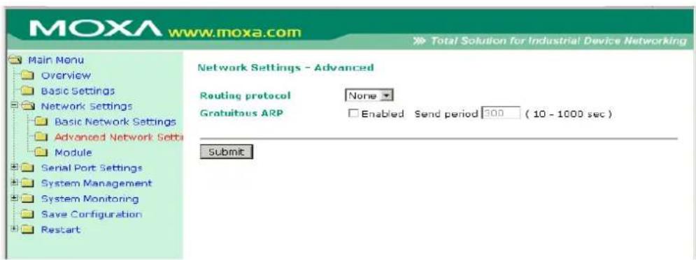
What is RIP?
RIP (Routing Information Protocol) is a protocol used to manage routing information within a self-contained network, such as a corporate LAN (Local Area Network) or an interconnected group of such LANs.
By using RIP, a gateway host with a router can send its entire routing table, which lists all the other hosts it knows about, to its closest host every 30 seconds. The closest host in turn will pass this information on to its neighbor, and so on, until all the hosts within the network have the same routing path information. This state is known as network convergence. RIP uses a hop count as a way of determining network distance. (Other protocols use more sophisticated algorithms that also include timing.) After receiving a packet headed for a specific destination, a network host with a router uses the routing table information to determine the next host to route the packet to.
RIP is considered an effective solution for small homogeneous networks. For larger, more complicated networks, transmitting the entire routing table every 30 seconds can bog down the network with a lot of extra traffic.
RIP 2 is an extension of RIP. Its purpose is to expand the amount of useful information contained in RIP packets and to add security elements. RIP 2 has become the standard version of RIP, and the original RIP is no longer used.
Routing Protocol: You may select which routing protocol, if any, your network will employ.
Gratuitous ARP: In some applications, you may need the NPort 6000 to send broadcast packets to update the ARP table on the server. If you enable this function and set the send period, the NPort 6000 will send periodically send broadcast packets at the specified time interval.
Configuring the Route Table
You can access the Route Table by expanding System Management and then Misc. Network Settings in the navigation panel. The route table is where you configure how the NPort 6000 will connect to an outside network.
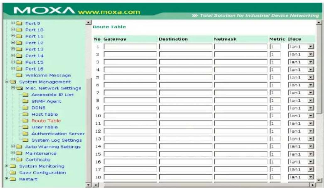
You are allowed up to 32 entries in the route table. For each entry, you must provide information on the gateway, destination, netmask, metric hops and interface.
Gateway: This is the IP address of the next-hop router.
Destination: This is the host's IP address or the network address of the route's destination.
Netmask: This is the destination network's netmask.
Metric: You may use this optional field to enter the number of hops from the source to the destination. This allows the NPort 6000 to prioritize the routing of data packets if more than one router is available to reach a given destination.
I face: This is the network interface to which the packet must be sent.

ATTENTION
When a serial port is configured for PPP/SLIP, the Iface field must be set to that serial port for proper communication.
Configuring Routes to the Internet
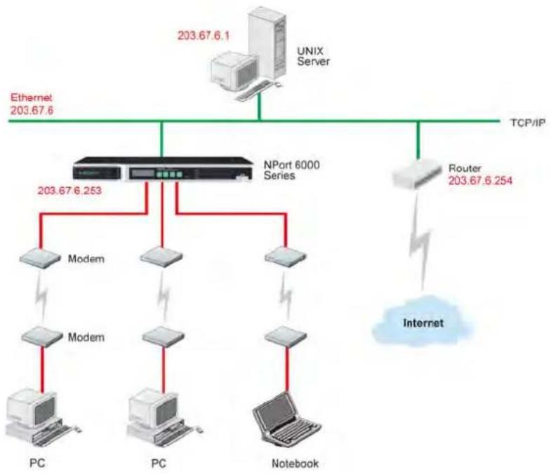
flowchart
graph TD
    A["203.67.6.1"] --> B["UNIX Server"]
    B --> C["TCP/IP"]
    C --> D["Router 203.67.6.254"]
    D --> E["Internet"]
    F["PC"] --> G["Modem"]
    H["PC"] --> I["Modem"]
    J["Notebook"] --> K["Modem"]
    L["Internet"] --> M["Router 203.67.6.254"]
    M --> N["NPort 6000 Series"]
    O["Ethernet 203.67.6"] --> P["203.67.6.253"]
In this example, the Notebook PC dials into the NPort 6000 to request a connection to the Internet host at 210.48.96.9, which is not on the local network 203.67.6.xxx. This causes the NPort 6000 to act as a router and send the datagram to the default next-hop router, 203.67.6.254. In this case, we should add the gateway IP address of 203.67.6.254 to the routing table to handle hops to 210.48.96.9.
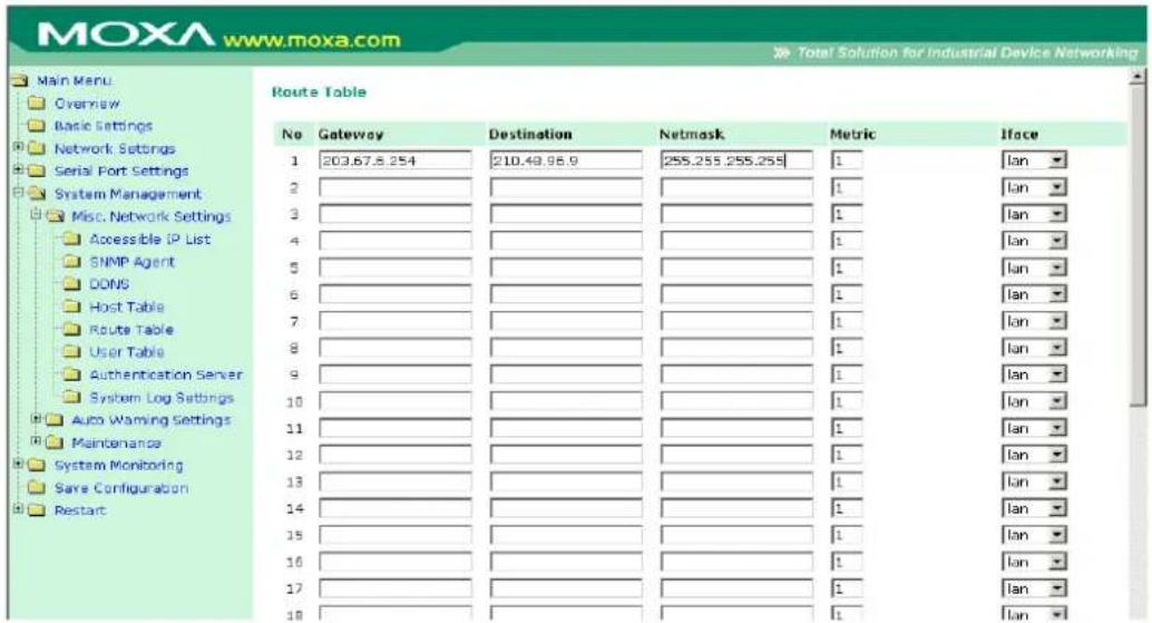
Generally, connections to the Internet are handled by assigning a gateway server in the network settings rather than through the route table.
Configuring Routes to the Intranet
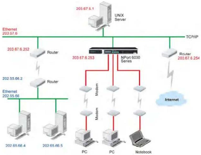
flowchart
graph TD
    A["203.67.6.1"] --> B["UNIX Server"]
    C["203.67.6.252"] --> D["Router"]
    E["203.67.6.253"] --> F["NPort 6000 Series"]
    G["203.67.6.254"] --> H["Router"]
    I["202.65.66.2"] --> J["Router"]
    K["202.65.66"] --> L["Ethernet 202.65.66.4"]
    M["202.65.66.5"] --> N["Ethernet 202.65.66"]
    O["PC"] --> P["Modem"]
    Q["PC"] --> R["Modem"]
    S["Notebook"] --> T["Modem"]
    U["Internet"] --> V["Router 203.67.6.254"]
In this example, dial-in users can make requests to Intranet hosts 202.65.66.4 or 202.65.66.5, which are on network 202.65.66.xxx (located outside network 203.67.6.xxx). You will need to add a route entry for the next-hop router, 203.67.6.252 that delivers requests to network 202.65.66.xxx. The metric hop in this case is 2 route hops.
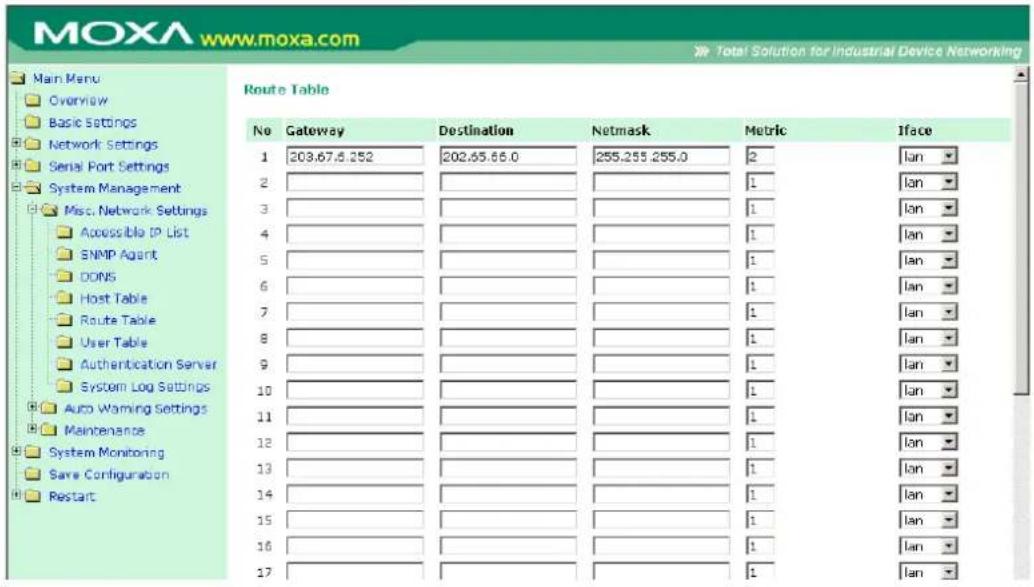
Configuring Multiple-point Routes
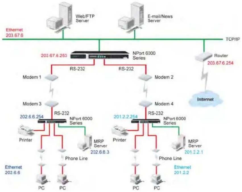
flowchart
graph TD
    A["Web/FTP Server"] --> B["RS-232"]
    C["E-mail/News Server"] --> D["RS-232"]
    E["TCP/IP"] --> F["Router 203.67.6.254"]
    B --> G["Modem 1"]
    D --> H["Modem 2"]
    G --> I["Modem 3"]
    H --> J["Modem 4"]
    I --> K["Printer"]
    I --> L["Phone Line"]
    J --> M["RS-232"]
    J --> N["RS-232"]
    K --> O["PC"]
    L --> P["PC"]
    M --> Q["MRP Server 202.6.6.3"]
    N --> R["MRP Server 201.2.2.1"]
    O --> S["Phone Line"]
    P --> T["Phone Line"]
    Q --> U["PC"]
    R --> V["PC"]
    W["Internet"] --> X["Router 203.67.6.254"]
    style A fill:#f9f,stroke:#333
    style C fill:#f9f,stroke:#333
    style E fill:#f9f,stroke:#333
    style W fill:#ccf,stroke:#333
For multilocation enterprises, NPort 6000 servers can be placed in different branch offices and used as both multipoint routers and as remote access servers. When hosts (e.g., the Web/FTP and E-mail/News servers shown in the figure) send requests to hosts on another network, such as 202.6.6.xxx or 201.2.2.xxx, the corresponding NPort 6000 delivers the request to the other NPort 6000 on the remote end, 202.6.6.254 or 201.2.2.254, as the next-hop router..
For this example, assume that Modem 1 is connected to serial port 1, Modem 2 is connected to serial port 2, and PPP source and destination IP addresses of modems 1, 2, 3, and 4 are as follows:
| Source IP | Destination IP | Source IP | Destination IP | ||
| Modem 1 | 203.67.6.250 | 202.6.6.250 | Modem 3 | 202.6.6.250 | 203.67.6.250 |
| Modem 2 | 203.67.6.249 | 201.2.2.249 | Modem 4 | 201.2.2.249 | 203.67.6.249 |
In this case, you will need to add two entries to the routing table, as shown in the following figure.
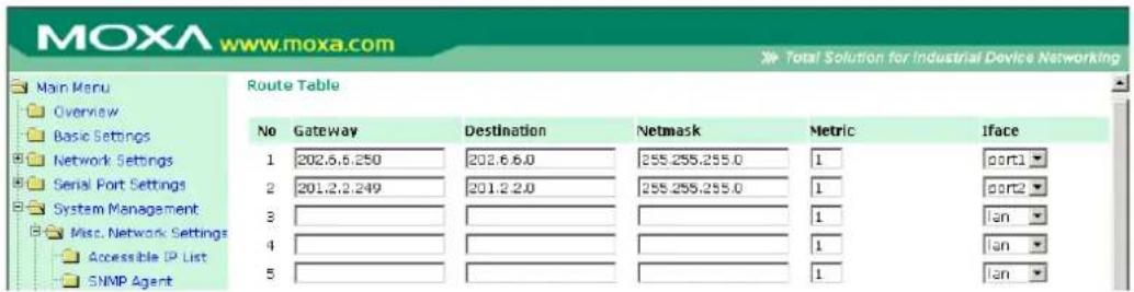
In this chapter, we describe additional settings related to the NM-TX01, NM-FX01-M-SC, NM-FX01-S-SC, NM-FX02-M-SC, and NM-FX02-S-SC modules. The same configuration options are also available from the Telnet and serial consoles.
The following topics are covered in this chapter:
□ NM-TX01, NM-TX02, NM-FX01-M-SC, NM-FX01-S-SC, NM-FX02-M-SC, NM-FX02-S-SC
➢ Using Ethernet Redundancy
The STP/RSTP Concept
➢ Differences between RSTP and STP
STP Example
□ Configuring Turbo Ring
The Turbo Ring Concept
➢ Configuring Turbo Ring 2
NM-TX01, NM-TX02, NM-FX01-M-SC, NM-FX01-S-SC, NM-FX02-M-SC, NM-FX02-S-SC
Using Ethernet Redundancy
Setting up Ethernet Redundancy on your NPort 6000 network helps protect critical links against failure, protects against network loops and achieves the Ring topology, and keeps network downtime at a minimum.
The Ethernet Redundancy function allows the user to implement several NPort 6000 units into a Ring topology to provide a backup data transmission route in the event that a cable is inadvertently disconnected or damaged. This is a particularly important feature for industrial applications, since it could take several minutes to troubleshoot, such as locating the disconnected or severed cable. Several minutes of downtime could cause a big loss in production and revenue. The NPort 6000 supports three different protocols for this Ethernet redundancy function—Rapid Spanning Tree Protocol (IEEE-802.1w), Turbo Ring, and Turbo Ring 2.

ATTENTION
The Ethernet redundancy function can be used with NPort 6450 and NPort 6600 units that have a network expansion slot and are equipped with any of the network extension modules listed below:
| NM-TX01/NM-TX01-T | Ethernet module with 1 RJ45 port |
| NM-TX02/NM-TX02-T | Ethernet module with2 RJ45 ports |
| NM-FX01-S-SC/NM-FX01-S-SC-T | Ethernet module with a single-mode fiber port and SC connector |
| NM-FX01-M-SC/NM-FX01-M-SC-T | Ethernet module with a multimode fiber port with SC connector |
| NM-FX02-S-SC/NM-FX02-S-SC-T | Ethernet module with 2 single-mode fiber ports with SC connectors |
| NM-FX02-M-SC/NM-FX02-M-SC-T | Ethernet module with 2 multimode fiber ports with SC connectors |
Turbo Ring," "Turbo Ring V2," and STP/RSTP protocols cannot be mixed on the same ring. The table below lists the key differences between each ring type. Use this information to evaluate the benefits of each; then, determine which features are most suitable for your network.
| Protocol STP RSTP | ||
| Topology | Ring, Mesh | Ring, Mesh |
| Recovery Time | Up to 30 sec | Up to 5 sec |
Moxa developed the proprietary Turbo Ring protocol to optimize communication redundancy and achieve a faster recovery time on the network. The protocol is implemented on both the Ethernet and the serial device server. Because of the differences in behavior of a switch compared with a device server, the recovery times will also differ.
| Protocol | Turbo Ring | Turbo Ring 2 | ||
| Topology Ring Ring | ||||
| Baudrate / Recovery Time | 921.6 kbps | Up to 100 ms | 921.6 kbps | Up to 100 ms |
| 9600 bps | Up to 40 ms | 9600 bps | Up to 20 ms | |
NOTE
The Recovery time is based on the setting "Real COM Mode, N, 8, 1, Hi-Performance, HW flow control" on NPort 6450 and performs the burn-in test for 8 hours. Implement NPort 6000 in the Turbo Ring Enable Switch back bone may slow down the recovery time to hundred milli-seconds due to the different operation behaviors of NPort 6000.
The STP/ RSTP Concept
Spanning Tree Protocol (STP) was designed to help reduce link failures on a network and provide protection from loops. Networks that have a complicated architecture are prone to broadcast storms caused by unintended loops on the network. The Moxa NPort 6000's STP feature is disabled by default. To be completely effective, you must enable RSTP/STP on every NPort 6000 connected to your network.
Rapid Spanning Tree Protocol (RSTP) implements the Spanning Tree Algorithm and Protocol defined by IEEE Std 802.1w-2001. RSTP provides the following benefits:
- The topology of a bridged network will be determined much more quickly compared to STP.
- RSTP is backwards compatible with STP, making it relatively easy to deploy. For example:
➢ Defaults to sending 802.1D style BPDUs if packets with this format are received.
➢ STP (802.1D) and RSTP (802.1w) can operate on different ports of the same NPort 6000.
This feature is particularly helpful when the NPort 6000 ports are connected to older equipment, such as legacy NPort 6000s.
You get essentially the same functionality with RSTP and STP. To see how the two systems differ, see the "Differences between RSTP and STP" section in this chapter.
NOTE The STP protocol is part of the IEEE Std 802.1D, 1998 Edition bridge specification. The explanation given in the following section uses bridge instead of NPort 6000.
What is STP?
STP (802.1D) is a bridge-based system that is used to implement parallel paths for network traffic. STP uses a loop-detection process to:
- Locate and then disable less efficient paths (i.e., paths that have a lower bandwidth).
- Enable one of the less efficient paths if the most efficient path fails.
The figure below shows a network made up of three LANs separated by three bridges. Each segment uses at most two paths to communicate with the other segments. Since this configuration can give rise to loops, the network will overload if STP is NOT enabled.
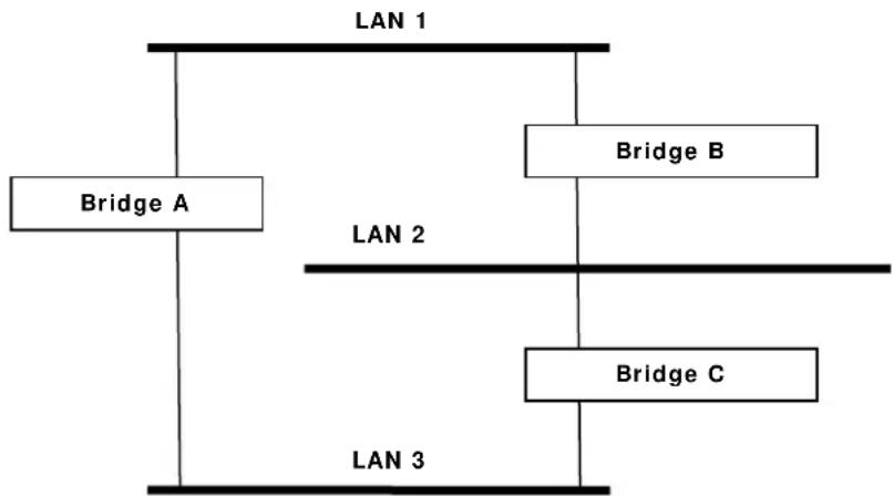
flowchart
graph TD
    A["LAN 1"] --> B["Bridge A"]
    A --> C["Bridge B"]
    A --> D["Bridge C"]
    B --> E["LAN 2"]
    C --> F["LAN 2"]
    D --> G["LAN 3"]
If STP is enabled, it will detect duplicate paths and prevent, or block, one of them from forwarding traffic. In the following example, STP determined that traffic from LAN segment 2 to LAN segment 1 should flow through Bridges C and A because this path has a greater bandwidth and is therefore more efficient.
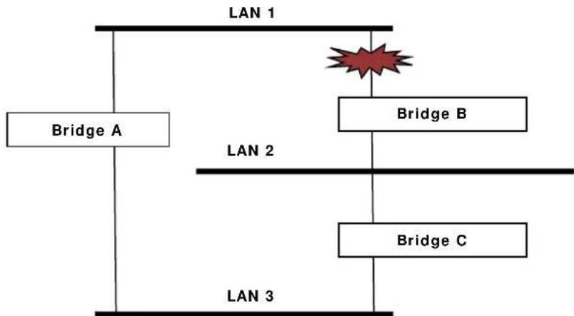
flowchart
graph TD
    A["Bridge A"] --> B["Bridge B"]
    B --> C["Bridge C"]
    C --> D["LAN 3"]
    E["LAN 1"] --> F["Red Star"]
    style E fill:#f9f,stroke:#333
    style F fill:#ccf,stroke:#333
What happens if a link failure is detected? As shown in next figure, the STP process reconfigures the network so that traffic from LAN segment 2 flows through Bridge B.
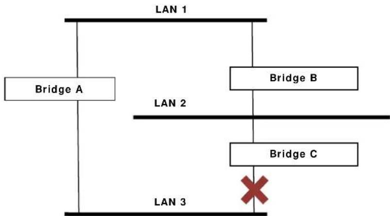
flowchart
graph TD
    A["Bridge A"] --> B["Bridge B"]
    B --> C["Bridge C"]
    C --> D["×"]
    style D fill:#f9f,stroke:#333
STP will determine which path between each bridged segment is the most efficient and then assign a specific reference point on the network. When the most efficient path has been identified, the other paths are blocked. In the above 3 figures, STP first determined that the path through Bridge C was the most efficient, and as a result, blocked the path through Bridge B. After the failure of Bridge C, STP re-evaluated the situation and opened the path through Bridge B.
How STP Works
When enabled, STP determines the most appropriate path for traffic through a network. The way it does this is outlined in the sections below.
STP Requirements
Before STP can configure the network, the system must satisfy the following requirements:
- Communication between all the bridges. This communication is carried out using Bridge Protocol Data Units (BPDUs), which are transmitted in packets with a known multicast address.
- Each bridge must have a Bridge Identifier that specifies which bridge acts as the central reference point, on a Root Bridge, for the STP system—bridges with a lower Bridge Identifier are more likely to be designated as the Root Bridge. The Bridge Identifier is calculated using the MAC address of the bridge and a priority defined for the bridge. The default priority of the NPort 6000 series is 32768.
- Each port has a cost that specifies the efficiency of each link. The efficiency cost is usually determined by the bandwidth of the link, with less efficient links assigned a higher cost.
STP Calculation
The first step of the STP process is to perform calculations. During this stage, each bridge on the network transmits BPDUs. The following items will be calculated:
- Which bridge should be the Root Bridge? The Root Bridge is the central reference point from which the network is configured.
- The Root Path Costs for each bridge. This is the cost of the paths from each bridge to the Root Bridge.
- The identity of each bridge's Root Port. The Root Port is the port on the bridge that connects to the Root Bridge via the most efficient path. In other words, the port connected to the Root Bridge via the path with the lowest Root Path Cost. The Root Bridge, however, does not have a Root Port.
- The identity of the Designated Bridge for each LAN segment. The Designated Bridge is the bridge with the lowest Root Path Cost from that segment. If several bridges have the same Root Path Cost, the one with the lowest Bridge Identifier becomes the Designated Bridge. Traffic transmitted in the direction of the Root Bridge will flow through the Designated Bridge. The port on this bridge that connects to the segment is called the Designated Bridge Port.
STP Configuration
After all the bridges on the network agree on the identity of the Root Bridge, and all other relevant parameters have been established, each bridge is configured to forward traffic only between its Root Port and the Designated Bridge Ports for the respective network segments. All other ports are blocked, which means that they will not be allowed to receive or forward traffic.
STP Reconfiguration
Once the network topology has stabilized, each bridge listens for Hello BPDUs transmitted from the Root Bridge at regular intervals. If a bridge does not receive a Hello BPDU after a certain interval (the Max Age time), the bridge assumes that the Root Bridge, or a link between itself and the Root Bridge, has gone down. This will trigger the bridge to reconfigure the network to account for the change. If you have configured an SNMP trap destination, the first bridge to detect the change sends out an SNMP trap when the topology of your network changes.
Differences between RSTP and STP
RSTP is similar to STP, but it includes additional information in the BPDUs that allows each bridge to confirm that it has taken action to prevent loops from forming when it decides to enable a link to a neighboring bridge. Adjacent bridges connected via point-to-point links will be able to enable a link without waiting to ensure that all other bridges in the network have had time to react to the change. The main benefit of RSTP is that the configuration decision is made locally rather than network-wide, allowing RSTP to carry out automatic configuration and restore a link faster than STP.
STP Example
The LAN shown below has three segments, with adjacent segments connected using two possible links. The various STP factors, such as Cost, Root Port, Designated Bridge Port, and Blocked Port are shown in the figure.
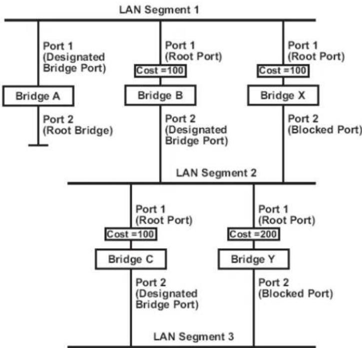
flowchart
graph TD
    A["LAN Segment 1"] --> B["Port 1 (Designated Bridge Port)"]
    A --> C["Port 1 (Root Port)"]
    A --> D["Port 1 (Root Port)"]
    B --> E["Bridge A"]
    C --> F["Bridge B"]
    D --> G["Bridge X"]
    E --> H["Port 2 (Root Bridge)"]
    F --> I["Port 2 (Designated Bridge Port)"]
    G --> J["Port 2 (Blocked Port)"]
    H --> K["LAN Segment 2"]
    I --> K
    J --> K
    K --> L["Port 1 (Root Port)"]
    K --> M["Port 1 (Root Port)"]
    L --> N["Cost =100"]
    M --> O["Cost =200"]
    N --> P["Bridge C"]
    O --> Q["Bridge Y"]
    P --> R["Port 2 (Designated Bridge Port)"]
    Q --> S["Port 2 (Blocked Port)"]
    R --> T["LAN Segment 3"]
    S --> T
- Bridge A has been selected as the Root Bridge, since it was determined to have the lowest Bridge Identifier on the network.
- Since Bridge A is the Root Bridge, it is also the Designated Bridge for LAN segment 1. Port 1 on Bridge A is selected as the Designated Bridge Port for LAN Segment 1.
- Ports 1 of Bridges B, C, X, and Y are all Root Ports since they are the nearest to the Root Bridge, and therefore have the most efficient path.
- Bridges B and X offer the same Root Path Cost for LAN segment 2. However, Bridge B was selected as the Designated Bridge for that segment since it has a lower Bridge Identifier. Port 2 on Bridge B is selected as the Designated Bridge Port for LAN Segment 2.
- Bridge C is the Designated Bridge for LAN segment 3, because it has the lowest Root Path Cost for LAN Segment 3:
The route through Bridges C and B costs 200 (C to B=100, B to A=100)
The route through Bridges Y and B costs 300 (Y to B=200, B to A=100)
• The Designated Bridge Port for LAN Segment 3 is Port 2 on Bridge C.
Configuring RSTP
Redundancy Settings
| Redundancy protocol | RSTP (IEEE 802.1W/1D) |
| Bridge priority | 32768 |
| Hello Time | 2 (1 - 10 sec) |
| Forward Delay | 15 (4 - 30 sec) |
| Max Age [Hint] | 20 (6 - 40 sec) |
| Port | Enable RSTP | Port Priority | Port Cost |
| 1 | 128 | 200000 | |
| 2 | 128 | 200000 |
Submit
Bridge priority
| Setting | Description | Factory Default |
| Numerical value selected by user | Increase this device's bridge priority by selecting a lower number. A device with a higher bridge priority has a greater chance of being established as the root of the Spanning Tree topology. | 32768 |
Hello time (sec.)
| Setting | Description | Factory Default |
| Numerical value input by user | The root of the Spanning Tree topology periodically sends out a “hello” message to other devices on the network to check if the topology is healthy. The “hello time” is the amount of time the root waits between sending hello messages. | 2 |
Forward Delay
| Setting | Description | Factory Default |
| Numerical value input by user | The amount of time this device waits before checking to see if it should change to a different state. | 15 (sec.) |
Max. Age (sec.)
| Setting | Description | Factory Default |
| Numerical value input by user | If this device is not the root, and it has not received a hello message from the root in an amount of time equal to “Max. Age,” then this device will reconfigure itself as a root. Once two or more devices on the network are recognized as a root, the devices will renegotiate to set up a new Spanning Tree topology. | 20 |
Enable STP per Port
| Setting | Description | Factory Default |
| Enable/Disable | Select to enable the port as a node on the Spanning Tree topology. | Disabled |
Configuration Limits of RSTP/ STP
The Spanning Tree Algorithm places limits on three of the configuration items described above:
[Eq. 1]: 1 sec ≤ Hello Time ≤ 10 sec
[Eq. 2]: 6 sec ≦ Max. Age ≦ 40 sec
[Eq. 3]: 4 sec ≤ Forwarding Delay ≤ 30 sec
These three variables are further restricted by the following two inequalities:
[Eq. 4]: 2 x (Hello Time + 1 sec) ≤ Max. Age ≤ 2 x (Forwarding Delay - 1 sec)
The NPort 6000's firmware will alert you immediately if any of these restrictions are violated. For example, setting
Hello Time = 5 sec, Max. Age = 20 sec, and Forwarding Delay = 4 sec does not violate Eqs. 1 through 3, but does violate Eq. 4, since in this case,
2 x (Hello Time + 1 sec) = 12 sec, and 2 x (Forwarding Delay - 1 sec) = 6 sec.
You can remedy the situation in any number of ways. One solution is simply to increase the Forwarding Delay value to at least 11 sec.
HINT: Take the following steps to avoid guessing:
Step 1: Assign a value to "Hello Time" and then calculate the leftmost part of Eq. 4 to get the lower limit of "Max. Age".
Step 2: Assign a value to "Forwarding Delay" and then calculate the rightmost part of Eq. 4 to get the upper limit for "Max. Age".
Step 3: Assign a value to "Forwarding Delay" that satisfies the conditions in Eq. 3 and Eq. 4.
Configuring Turbo Ring
The Turbo Ring Concept
Moxa developed the proprietary Turbo Ring protocol to optimize communication redundancy and achieve a faster recovery time on the network. The Turbo Ring and Turbo Ring V2 protocols identify one NPort 6000 as the master of the network and then automatically block packets from traveling through any of the network's redundant loops.
In the event that one branch of the ring gets disconnected from the rest of the network, the protocol automatically readjusts the ring so that the part of the network that was disconnected can reestablish contact with the rest of the network.
| Initial setup of a “Turbo Ring” or “Turbo Ring V2” ring | |
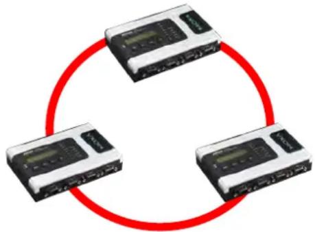 | 1. Select any two ports as redundant ports.2. Connect the redundant ports to form the Turbo Ring. |
The user does not need to configure any of the NPort 6000 units as the master to use Turbo Ring or Turbo Ring V2. If none of the NPort 6000 in the ring is configured as the master, then the protocol will automatically assign master status to one of the NPort 6000 units. In fact, the master is only used to identify which segment in the redundant ring acts as the backup path. In the following subsections, we explain how the redundant path is selected for rings configured for Turbo Ring and Turbo Ring V2.
Determining the Redundant Path of a "Turbo Ring" Ring
In this case, the redundant segment (i.e., the segment that will be blocked during normal operation) is determined by the number of EDS units that make up the ring and where the ring master is located
When the number of NPort 6000 units in the Turbo Ring is even.
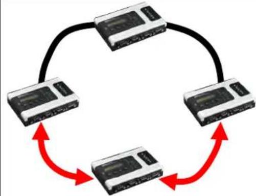
flowchart
graph TD
    A["Device 1"] --> B["Device 2"]
    B --> C["Device 3"]
    C --> D["Device 4"]
    D --> A
    style A fill:#f9f,stroke:#333
    style B fill:#f9f,stroke:#333
    style C fill:#f9f,stroke:#333
    style D fill:#f9f,stroke:#333
If there are 2N NPort 6000 units (an even number) in the Turbo Ring, then the backup segment is one of the two segments connected to the (N + 1) st NPort 6000 (i.e., the NPort 6000 unit directly opposite the master).
When the number of NPort 6000 units in the Turbo Ring is odd.
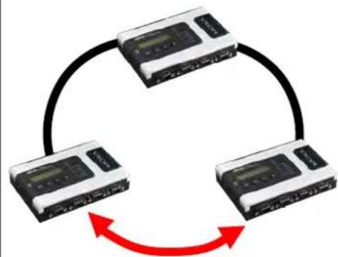
flowchart
graph TD
    A["Device 1"] --> B["Device 2"]
    B --> C["Device 3"]
    C --> A
    style A fill:#f9f,stroke:#333
    style B fill:#f9f,stroke:#333
    style C fill:#f9f,stroke:#333
If there are 2N+1 NPort 6000 units (an odd number) in the Turbo Ring, with NPort 6000 units and segments labeled counterclockwise, then segment N+1 will serve as the backup path.
For the example shown here, N=1, and therefore N+1=2 .
Turbo Ring Settings
Redundancy Protocol
Master
1st Redundant Port
2nd Redundant Port
Turbo Ring


Enable
Disable


Submit
Master
| Setting | Description | Factory Default |
| Enable/Disable | Enable or Disable this NPort 6000 as the master | Disable |
Redundant Ports
| Setting | Description | Factory Default |
| 1st Redundant Port | Select any LAN port of the NPort 6000 to be one of the redundant ports. | Port 1 |
| 2nd Redundant Port | Select any LAN port of the NPort 6000 to be one of the redundant ports. | Port 2 |
Configuring Turbo Ring 2
Turbo Ring Settings
Redundancy Protocol
Master
1st Redundant Port
2nd Redundant Port
Turbo Ring V2
Enable
Disable
1
2
Submit
Master
| Setting | Description | Factory Default |
| Enable/Disable | Enable or Disable this NPort 6000 as the master. | Disable |
Redundant Ports
| Setting | Description | Factory Default |
| 1st Redundant Port | Select any LAN port of the NPort 6000 to be one of the redundant ports. | Port 1 |
| 2nd Redundant Port | Select any LAN port of the NPort 6000 to be one of the redundant ports. | Port 2 |
In this chapter, we explain how to configure the individual serial port modes.
The following topics are covered in this chapter:
□ Port Setting Basics
□ Device Control Applications
Real COM Mode
▶ Reverse Real COM Mode
RFC2217 Mode
□ Socket Applications
TCP Server Mode
TCP Client Mode
▶ UDP Mode
□ Pair Connection Mode
➢ Pair Connection Master Mode
➢ Pair Connection Slave Mode
☐ Ethernet Modem Mode
☐ Terminal Applications
Terminal ASCII (TERM_ASC)
Terminal BIN (TERM_BIN)
SSH
☐ Reverse Terminal Applications
➢ Reverse Telnet Mode
Reverse SSH Mode
□ Printer Applications
RAW PRN Mode
LPD PRN Mode
☐ Dial In/ Out Applications
PPP Mode
PPPD Mode
SLIP Mode
SLIPD Mode
Dynamic Mode
□ Disabled Mode
Port Setting Basics
Each serial port on the NPort 6000 can be configured independently. To configure the operation mode and settings for a port, expand Serial Port Settings in the navigation panel; then expand the port that you would like to configure. Individual port settings are grouped into four categories in the navigation panel: Operation Modes, Communication Parameters, Data Buffering/Log, and Modem Settings.
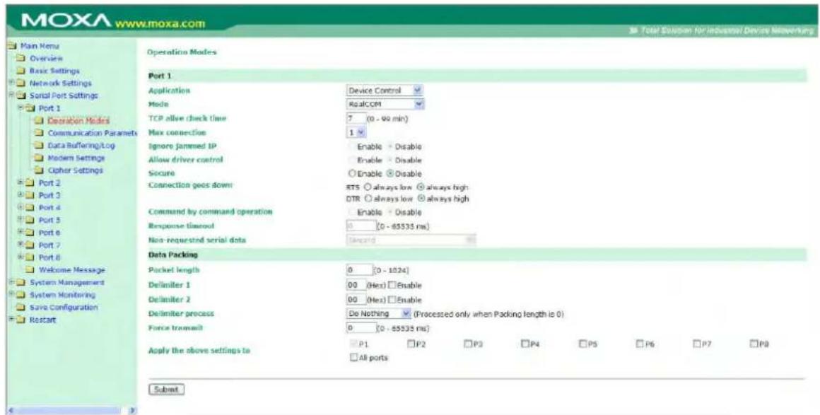
Select Operation Modes in the navigation panel to select and configure the mode for each serial port. For NPort 6000 models with 2 or more serial ports, you may use the checkboxes at the bottom of the window to apply the settings to one or more ports.
Application: Select an application for the serial port from among the choices. Your application will determine the modes that are available.
Mode: Once you have chosen an application, select the mode. The available configuration settings will vary depending on the mode that you have selected.
Device Control Applications
Real COM Mode
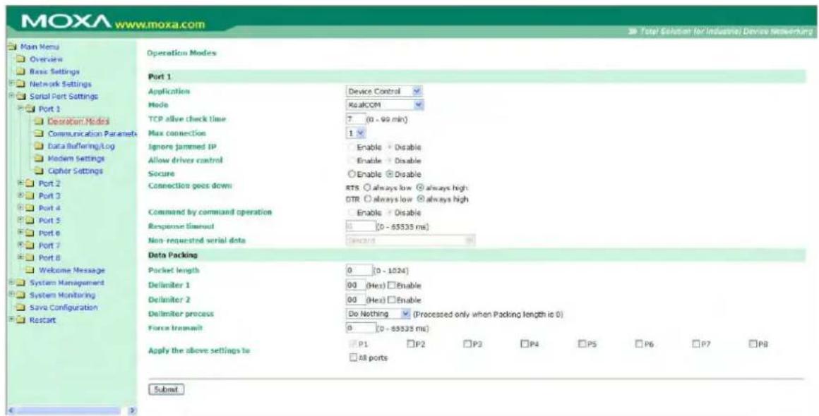
TCP alive check time (default=7 min): This field specifies how long the NPort 6000 will wait for a response to keep-alive packets before closing the TCP connection. The NPort 6000 checks connection status by sending periodic keep-alive packets. If the remote host does not respond to the packet within the time specified in this field, the NPort 6000 will force the existing TCP connection to close. For socket and device control modes, the NPort 6000 will listen for another TCP connection from another host after closing the connection. If TCP alive check time is set to 0, the TCP connection will remain open and will not send any keep-alive packets.
Max connection (default=1): This field is used if you need to receive data from different hosts simultaneously. When set to 1, only one specific host can access this port of the NPort 6000, and the Real COM driver on that host will have full control over the port. When set to 2 or greater, up to the specified number of hosts' Real COM drivers may open this port at the same time. When multiple hosts' Real COM drivers open the port at the same time, the COM driver only provides a pure data tunnel—no control ability. The serial port parameters will use firmware settings instead of depending on your application program (AP).
Application software that is based on the COM driver will receive a driver response of "success" when the software uses any of the Win32 API functions. The firmware will only send data back to the driver on the host.
Data will be sent first-in first-out when it enters the NPort 6000 from the Ethernet interface.

ATTENTION
When Max connection is greater than 1, the NPort 6000 will use a multiconnection application (i.e., 2 to 8 hosts are allowed access to the port at the same time). When using a multiconnection application, the NPort 6000 will use the serial communication parameters as defined here in the web console, and all the hosts connected to the port must use identical serial settings. If one of the hosts opens the COM port with different serial settings, data will not be transmitted properly.
Ignore jammed IP (default=No): This option determines how the port will proceed if multiple hosts are connected and one or more of the hosts stops responding as the port is transmitting data. If you select No, the port will wait until the data has been transmitted successfully to all of the hosts before transmitting the next group of data. If you select Yes, the port will ignore the host that stopped responding and continue data transmission to the other hosts.
Allow driver control (default=No): This option determines how the port will proceed if driver control commands are received from multiple hosts that are connected to the port. If No is selected, driver control commands will be ignored. If Yes is selected, control commands will be accepted, with the most recent command received taking precedence.
Secure (default=No): If you select Yes, data sent through the Ethernet will be encrypted with SSL.

ATTENTION
If your NPort 6000 serial port is in Real COM mode and configured for SSL encryption, make sure the Real COM driver is configured the same way. This is done through NPort Windows Driver Manager, which is installed with the driver. Please refer to Chapter 10, Software Installation/Configuration, for more information.
Connection goes down (default=always high): You can configure what happens to the RTS and DTR signals when the Ethernet connection goes down. For some applications, serial devices need to know the Ethernet link status through RTS or DTR signals sent via the serial port. Use goes low if you want the RTS and DTR signal to change their state to low when the Ethernet connection goes down. Use always high if you do not want the Ethernet connection status to affect the RTS or DTR signals.
Command by command operation (default
= Disable) : Command by command mode can only support one request and one response from each host. When the NPort 6000 receives a command from any host on the Ethernet, the NPort 6000 will store the command in the buffer. Commands will be sent to the serial ports on a FIFO (first-in first-out) basis. See the diagram below:
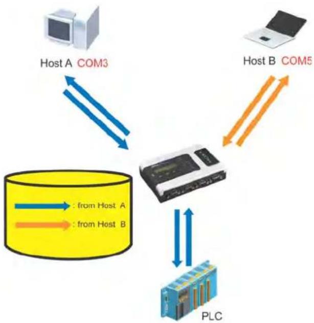
flowchart
graph TD
    A["Host A COM3"] -->|Data Flow 1| C["Central Device"]
    B["Host B COM5"] -->|Data Flow 2| C
    C -->|Data Flow 3| D["PLC"]
    D -->|Data Flow 4| C
    C -->|Data Flow 5| E["Yellow Cylinder"]
    style A fill:#f9f,stroke:#333
    style B fill:#f9f,stroke:#333
    style C fill:#ccf,stroke:#333
    style D fill:#cff,stroke:#333
    style E fill:#ffc,stroke:#333
Once the PLC responds, the NPort 6000 will save that response to its buffer, assuming that the response is correct and then send the command back to the originator of the command. The NPort 6000 can respond in place of the PLC the next time it receives a request for the same command.
Response timeout (default=0 ms): This field specifies how long the NPort 6000 will wait for response data through the serial port before sending the next command. The NPort 6000 sends the next command if there is no response through the serial port for the time specified by the Response timeout. If this field is set to 0, the Response timeout is essentially infinite, and the NPort 6000 will wait until the pre-command request is received to send the next command.
Non-requested serial data (default=discard): Specifies how the NPort will handle data that is received from a serial device that is not in response to a command. The NPort can either discard such data, forward the data to the network host that sent the most recent request, or forward the data to all open host connections.
- Discard: Discard the data
• Forward to last requester: Forward non-requested serial data to last requester connection - Forward to all open connections: Forward non-requested serial data to all open connections
Packet length (default=0): The packet length setting refers to the maximum amount of data that is allowed to accumulate in the serial port buffer before sending. At the default of 0 for packet length, no maximum amount is specified, and data in the buffer will be sent as specified by the delimiter settings or when the buffer is full. When a packet length between 1 and 1024 bytes is specified, data in the buffer will be sent as soon it reaches the specified length.
Delimiter 1 and Delimiter 2 (default=None): When Delimiter 1 is enabled, the serial port will clear the buffer and send the data to the Ethernet port when a specific character, entered in hex format, is received. A second delimiter character may be enabled and specified in the Delimiter 2 field, so that both characters act as the delimiter to control when data should be sent.

ATTENTION
In order to enable a delimiter, the packet length must be set to 0. Delimiter 2 should only be enabled in conjunction with Delimiter 1 and never on its own; otherwise, data errors may occur. Even when a delimiter is enabled, the NPort 6000 will still pack and send the data when the amount of data exceeds 1 KB.
Delimiter process (default=Do Nothing): The Delimiter process field determines how the data is handled when a delimiter is received. Delimiter 1 must be enabled for this field to have an effect. If Delimiters 1 and 2 are both enabled, both characters must be received for the delimiter process to take place.
- Do Nothing: Data in the buffer will be transmitted when the delimiter is received.
- Delimiter + 1: Data in the buffer will be transmitted after 1 additional byte is received following the delimiter.
- Delimiter + 2: Data in the buffer will be transmitted after 2 additional bytes are received following the delimiter.
- Strip Delimiter: Data in the buffer is first stripped of the delimiter before being transmitted.
Force transmit (default=0 ms): This parameter defines how large a gap in serial communication the NPort 6000 will allow before packing the serial data in its internal buffer for network transmission.
Reverse Real COM Mode
Operation Modes
Port 1
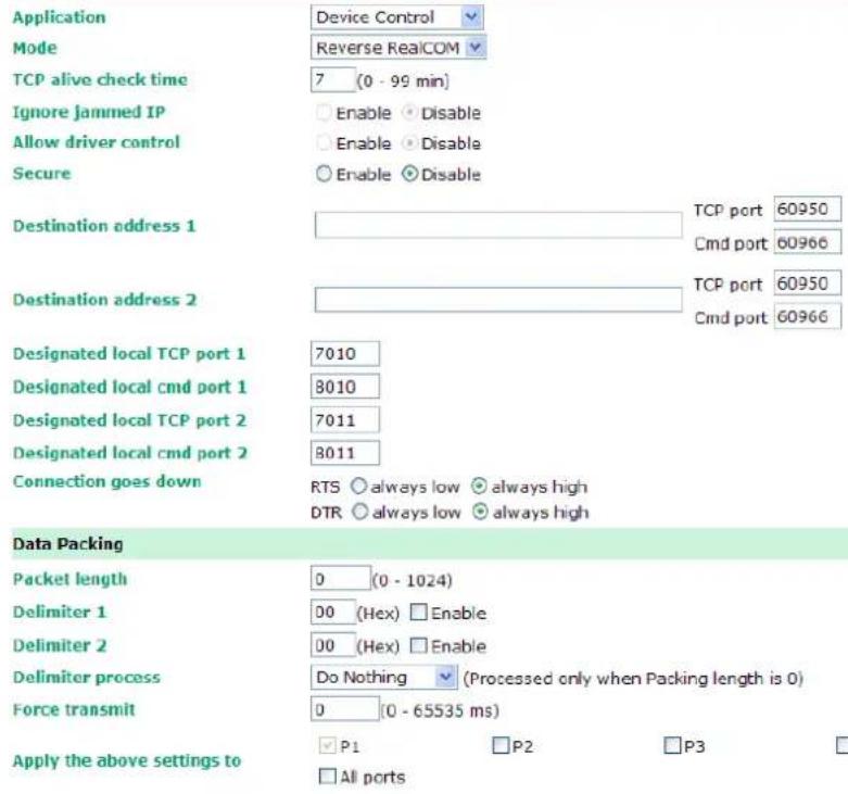
Submit
TCP alive check time (default=7 min): This field specifies how long the NPort 6000 will wait for a response to keep-alive packets before closing the TCP connection. The NPort 6000 checks the connection status by sending periodic keep-alive packets. If the remote host does not respond to the packet within the time specified in this field, the NPort 6000 will force the existing TCP connection to close. For socket and device control modes, the NPort 6000 will listen for another TCP connection from another host after closing the connection. If TCP alive check time is set to 0, the TCP connection will remain open and will not send any keep-alive packets.
Ignore jammed IP (default=Disable): This option determines how the Nport will proceed if multiple hosts are connected and one or more of the hosts stops responding as the port is transmitting data. If you select disable, the port will wait until the data has been transmitted successfully to all the hosts before transmitting the next group of data. If you select Enable, the port will ignore the host that stopped responding and continue data transmission to the other hosts.
Allow driver control (default=Disable): This option determines how the port will proceed if driver control commands are received from multiple hosts that are connected to the port. If disable is selected, driver control commands will be ignored. If Enable is selected, control commands will be accepted, with the most recent command received taking precedence.
Secure (default=Disable): If you select Enable, data sent through the Ethernet will be encrypted with SSL.

ATTENTION
If an NPort 6000 serial port is in Reverse Real COM mode and configured for SSL encryption, make sure the Reverse Real COM driver is configured the same way. This is done through the NPort Windows Driver Manager, which is installed with the driver. Please refer to Chapter 10, Software Installation and Configuration, for more information.
Destination address 1 through 2 (default=None): Specifying an IP address allows the NPort 6000 to connect actively to the remote host. At least one destination must be provided.
TCP port (default=60950): This is the TCP port number assignment for the Remote Host/Server. It is the port number that the serial port of NPort 6000 uses to establish the connections with a Remote Host/Server. To avoid conflicts with well known TCP ports, the default is set to 60950.

ATTENTION
Up to 2 connections can be established between the NPort 6000 hosts. Make sure that port 60950 is not blocked by the firewall before using this port.

ATTENTION
The destination IP address parameter can be the IP address, domain name, or the name defined in the host table.
Designated local port 1 through 2 (default=7010 through 7320): Use these fields to specify the designated local ports.
Connection goes down (default=always high): You can configure what happens to the RTS and DTR signals when the Ethernet connection goes down. For some applications, serial devices need to know the Ethernet link status through RTS or DTR signals sent via the serial port. Use "always low" if you want the RTS and DTR signal to change their state to low when the Ethernet connection goes down. Use "always high" if you do not want the Ethernet connection status to affect the RTS or DTR signals.
Packet length (default=0): The packet length setting refers to the maximum amount of data that is allowed to accumulate in the serial port buffer before sending. At the default of 0 for packet length, no maximum amount is specified and data in the buffer will be sent as specified by the delimiter settings or when the buffer is full. When a packet length between 1 and 1024 bytes is specified, data in the buffer will be sent as soon it reaches the specified length.
Delimiter 1 and Delimiter 2 (default=None): When Delimiter 1 is enabled, the serial port will clear the buffer and send the data to the Ethernet port when a specific character, entered in hex format, is received. A second delimiter character may be enabled and specified in the Delimiter 2 field, so that both characters act as the delimiter to control when data should be sent.

ATTENTION
In order to enable a delimiter, the packet length must be set to 0. Delimiter 2 should only be enabled in conjunction with Delimiter 1 and never on its own; otherwise, there may be data errors. Even when a delimiter is enabled, the NPort 6000 will still pack and send the data when the amount of data exceeds 1 KB.
Delimiter process (default= Do Nothing): The Delimiter process field determines how the data is handled when a delimiter is received. Delimiter 1 must be enabled for this field to have an effect. If Delimiters 1 and 2 are both enabled, both characters must be received for the delimiter process to take place.
- Do Nothing: Data in the buffer will be transmitted when the delimiter is received.
- Delimiter + 1: Data in the buffer will be transmitted after 1 additional byte is received following the delimiter.
- Delimiter + 2: Data in the buffer will be transmitted after 2 additional bytes are received following the delimiter.
- Strip Delimiter: Data in the buffer is first stripped of the delimiter before being transmitted.
Force transmit (default=0 ms): This parameter defines the size of a gap in serial communication the NPort 6000 will allow before packing the serial data in its internal buffer for network transmission.
As data is received through the serial port, it is stored by the NPort 6000 in the internal buffer. The NPort 6000 transmits data stored in the buffer via TCP/IP, but only when the internal buffer is full or as specified by the force transmit time. When set to 0, the force transmit time is disabled, and transmission is determined solely by the data in the internal buffer. At 1 to 65535, the TCP/IP protocol software will pack the serial data received when there is a gap in serial communication that exceeds the specified force transmit time.
The optimal force transmit time depends on your application, but it must be at least larger than one character interval within the specified baudrate. For example, let's assume that the serial port is set to 1200 bps, 8 data bits, 1 stop bit, and no parity. In this case, the total number of bits needed to send a character is 10 bits, and the time required to transfer one character is (10 (bits) / 1200 (bits/s)) × 1000 (ms/s) = 8.3 ms. Therefore, you should set the force transmit time to be larger than 8.3 ms, so in this case, it must be greater than or equal to 10 ms.
If it is necessary to send a series of characters in the same packet, the serial device will need to send that series of characters within the specified force transmit time, and the total length of data must be less than or equal to the NPort 6000's internal buffer size (1 KB per port).
Apply the above setting to NPort 6000 models with 2 or more serial ports, you may use the checkboxes at the bottom of the window to apply the settings to one or more ports.
RFC2217 Mode
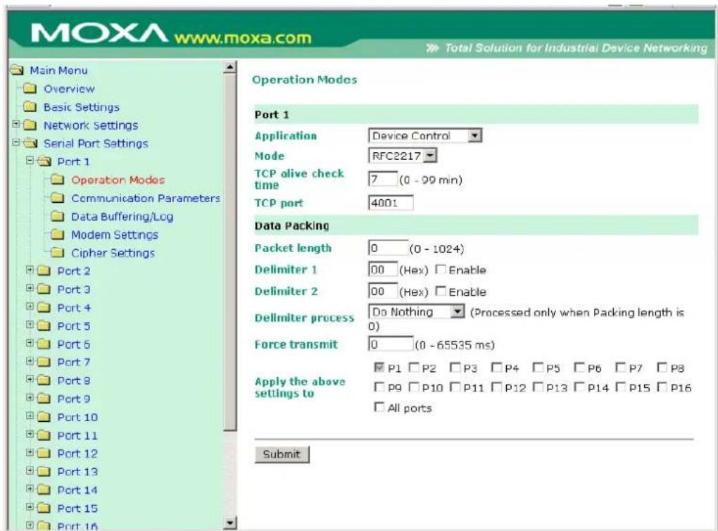
TCP alive check time (default=7 min): This field specifies how long the NPort 6000 will wait for a response to keep-alive packets before closing the TCP connection. The NPort 6000 checks connection status by sending periodic keep-alive packets. If the remote host does not respond to the packet within the time specified in this field, the NPort 6000 will force the existing TCP connection to close. For socket and device control modes, the NPort 6000 will listen for another TCP connection from another host after closing the connection. If TCP alive check time is set to 0, the TCP connection will remain open even if there is no response to the keep-alive packets.
TCP port (default=4001): This is the TCP port number assignment for the serial port on the NPort 6000. It is the port number that the serial port uses to listen to connections, and that other devices must use to contact the serial port. To avoid conflicts with well-known TCP ports, the default is set to 4001.
Packet length (default=0): The packet length setting refers to the maximum amount of data that is allowed to accumulate in the serial port buffer before sending. At the default of 0 for packet length, no maximum amount is specified and data in the buffer will be sent as specified by the delimiter settings or when the buffer is full. When a packet length between 1 and 1024 bytes is specified, data in the buffer will be sent as soon it reaches the specified length.
Delimiter 1 and Delimiter 2 (default=None): When Delimiter 1 is enabled, the serial port will clear the buffer and send the data to the Ethernet port when a specific character, entered in hex format, is received. A second delimiter character may be enabled and specified in the Delimiter 2 field, so that both characters act as the delimiter to indicate when data should be sent.

ATTENTION
In order to enable a delimiter, the packet length must be set to 0. Delimiter 2 should only be enabled in conjunction with Delimiter 1 and never on its own; otherwise, data errors may occur. Even when a delimiter is enabled, the NPort 6000 will still pack and send the data when the amount of data exceeds 1 KB.
Delimiter process (default=Do Nothing): The delimiter process field determines how the data is handled when a delimiter is received. Delimiter 1 must be enabled for this field to have an effect. If Delimiters 1 and 2 are both enabled, both characters must be received for the delimiter process to take place.
- Do Nothing: Data in the buffer will be transmitted when the delimiter is received.
- Delimiter + 1: Data in the buffer will be transmitted after 1 additional byte is received following the delimiter.
- Delimiter + 2: Data in the buffer will be transmitted after 2 additional bytes are received following the delimiter.
- Strip Delimiter: Data in the buffer is first stripped of the delimiter before being transmitted.
Force transmit (default=0 ms): This parameter defines how large a gap in serial communication the NPort 6000 will allow before packing the serial data in its internal buffer for network transmission.
Socket Applications
TCP Server Mode
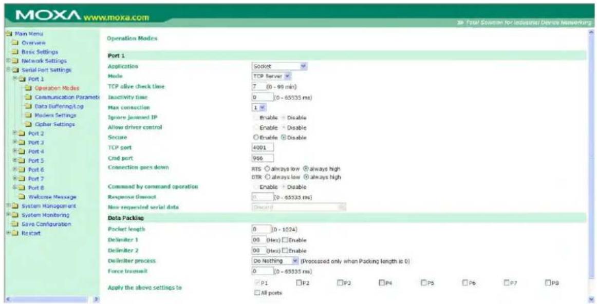
TCP alive check time (default=7 min.): This field specifies how long the NPort 6000 will wait for a response to keep-alive packets before closing the TCP connection. The NPort 6000 checks connection status by sending periodic keep-alive packets. If the remote host does not respond to the packet within the time specified in this field, the NPort 6000 will force the existing TCP connection to close. For socket and device control modes, the NPort 6000 will listen for another TCP connection from another host after closing the connection. If TCP alive check time is set to 0, the TCP connection will remain open even if there is no response to the keep-alive packets.
Inactivity time (default=0 ms): This field specifies how long the NPort 6000 will wait for incoming and outgoing data through the serial port before closing the TCP connection. The TCP connection is closed if there is no incoming or outgoing data through the serial port for the specified Inactivity time. If this field is set to 0, the TCP connection is kept active until a connection close request is received.

ATTENTION
If used, the Inactivity time setting should be greater than the Force transmit time. To prevent the unintended loss of data due to the session being disconnected, it is highly recommended that this value is set large enough so that the intended data transfer is completed.
Max connection (default=1): This field is used if you need to receive data from different hosts simultaneously. When set to 1, only a single host may open the TCP connection to the serial port. When set to 2 or greater, up to the specified number of hosts may open this port at the same time. When multiple hosts establish a TCP connection to the serial port at the same time, the NPort 6000 will duplicate the serial data and transmit it to all the hosts. Ethernet data is sent on a first-in first-out basis to the serial port when data enters the NPort 6000 from the Ethernet interface.
Ignore jammed IP (default=Disable): This option determines how the port will proceed if multiple hosts are connected and one or more of the hosts stops responding as the port is transmitting data. If you select Disable, the port will wait until the data has been transmitted successfully to all the hosts before transmitting the next group of data. If you select Enable, the port will ignore the host that stopped responding and continue data transmission to the other hosts.
Allow driver control (default=Disable): This option determines how the port will proceed if driver control commands are received from multiple hosts that are connected to the port. If Disable is selected, driver control commands will be ignored. If Enable is selected, control commands will be accepted, with the most recent command received taking precedence.
Secure (default=Disable): If you select Enable, data sent through the Ethernet will be encrypted with SSL.
TCP port (default=4001): This is the TCP port number assignment for the serial port on the NPort 6000. It is the port number that the serial port uses to listen to connections, and that other devices must use to contact the serial port. To avoid conflicts with well-known TCP ports, the default is set to 4001.
Command port (default=966): The Command port is the TCP port for listening to SSDK commands from the host. In order to prevent a TCP port conflict with other applications, the user can set the Command port to another port if needed.
Connection goes down (default=always high): You can configure what happens to the RTS and DTR signals when the Ethernet connection goes down. For some applications, serial devices need to know the Ethernet link status through RTS or DTR signals via through the serial port. Use goes low if you want the RTS and DTR signal to change their state to low when the Ethernet connection goes down. Use always high if you do not want the Ethernet connection status to affect the RTS or DTR signals.
Command by command operation
(default= Disable): Command by command mode can only support one request and one response from each of the different hosts. When the NPort 6000 receives a command from any host on the Ethernet, the NPort 6000 will store all the commands in the buffer and then send them to serial ports in FIFO (first-in, first-out) order.
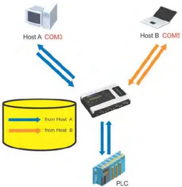
flowchart
graph TD
    A["Host A COM3"] -->|Data Flow Left| C["PLC"]
    B["Host B COM5"] -->|Data Flow Right| C
    C -->|Data Flow Down| D["Data From Host A"]
    C -->|Data Flow Up| E["Data From Host B"]
Once the PLC responds, the NPort 6000 will store the response in its buffer, decide that the response has been received, and then send back the command. The NPort 6000 will then be free to process the next command.
Response timeout (default=0 ms): This field specifies how long the NPort 6000 will wait for response data through the serial port before sending the next command. The NPort 6000 sends the next command if there is no response through the serial port for the time specified by the Response timeout. If this field is set to 0, the Response timeout is essentially infinite, and the NPort 6000 will wait until the pre-command request is received to send the next command.
Non-requested serial data (default=discard): Specifies how the NPort will handle data that is received from a serial device that is not in response to a command. The NPort can either discard such data, forward the data to the network host that sent the most recent request, or forward the data to all open host connections.
• Discard: Discard the data
- Forward to last requester: Forward non-requested serial data to last requester connection
- Forward to all open connections: Forward non-requested serial data to all open connections
Packet length (default=0): The packet length setting refers to the maximum amount of data that is allowed to accumulate in the serial port buffer before sending. At the default of 0 for packet length, no maximum amount is specified and data in the buffer will be sent as specified by the delimiter settings or when the buffer is full. When a packet length between 1 and 1024 bytes is specified, data in the buffer will be sent as soon it reaches the specified length.
Delimiter 1 and Delimiter 2 (default=None): When Delimiter 1 is enabled, the serial port will clear the buffer and send the data to the Ethernet port when a specific character, entered in hex format, is received. A second delimiter character may be enabled and specified in the Delimiter 2 field, so that both characters act as the delimiter to indicate when data should be sent.

ATTENTION
In order to enable a delimiter, packet length must be set to 0. Delimiter 2 should only be enabled in conjunction with Delimiter 1 and never on its own; otherwise, data errors may occur. Even when a delimiter is enabled, the NPort 6000 will still pack and send the data when the amount of data exceeds 1 KB.
Delimiter process (default=Do Nothing): The Delimiter process field determines how the data is handled when a delimiter is received. Delimiter 1 must be enabled for this field to have an effect. If Delimiters 1 and 2 are both enabled, both characters must be received for the delimiter process to take place.
- Do Nothing: Data in the buffer will be transmitted when the delimiter is received.
- Delimiter + 1: Data in the buffer will be transmitted after 1 additional byte is received following the delimiter.
- Delimiter + 2: Data in the buffer will be transmitted after 2 additional bytes are received following the delimiter.
- Strip Delimiter: Data in the buffer is first stripped of the delimiter before being transmitted.
Force transmit (default=0 ms): This parameter defines the size of a gap in serial communication the NPort 6000 will allow before packing the serial data in its internal buffer for network transmission.
TCP Client Mode
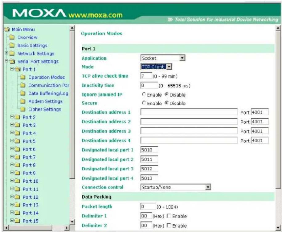
TCP alive check time (default=7 min): This field specifies how long the NPort 6000 will wait for a response to keep-alive packets before closing the TCP connection. The NPort 6000 checks connection status by sending periodic keep-alive packets. If the remote host does not respond to the packet within the time specified in this field, the NPort 6000 will force the existing TCP connection to close. For socket and device control modes, the NPort 6000 will listen for another TCP connection from another host after closing the connection. If TCP alive check time is set to 0, the TCP connection will remain open even if there is no response to the keep-alive packets.
Inactivity time (default=0 ms): This field specifies how long the NPort 6000 will wait for incoming and outgoing data through the serial port before closing the TCP connection. The TCP connection is closed if there is no incoming or outgoing data through the serial port for the specified Inactivity time. If this field is set to 0, the TCP connection is kept active until a connection close request is received.

ATTENTION
Inactivity time should at least be set larger than that of Force transmit time. To prevent the unintended loss of data due to the session being disconnected, it is highly recommended that this value is set large enough so that the intended data transfer is completed.

ATTENTION
Inactivity time is ONLY active when Connection Control (see below) is set to Any character/ Inactivity time.
Ignore jammed IP (default=Disable): This option determines how the port will proceed if multiple hosts are connected and one or more of the hosts stops responding as the port is transmitting data. If you select Disable, the port will wait until the data has been transmitted successfully to all the hosts before transmitting the next group of data. If you select Enable, the port will ignore the host that stopped responding and continue data transmission to the other hosts.
Secure (default= Disable): If you select Enable, data sent through the Ethernet will be encrypted with SSL.
Destination address 1 through 4 (default=None): Specifying an IP address allows the NPort 6000 to connect actively to the remote host. At least one destination must be provided.
TCP port (default=4001): This is the TCP port number assignment for the serial port on the NPort 6000. It is the port number that the serial port uses to listen to connections, and that other devices must use to contact the serial port. To avoid conflicts with well known TCP ports, the default is set to 4001.

ATTENTION
Up to 4 connections can be established between the NPort 6000 and hosts. The connection speed or throughput may be low if any one of the four connections is slow, since the one slow connection will slow down the other 3 connections.

ATTENTION
The Destination IP address parameter can be the IP address, domain name, or the name defined in the host table. For some applications, the user may need to send the data actively to the remote destination domain name.
Designated local port 1 through 4 (default=5010 through 5013): Use these fields to specify the designated local ports.
Connection control (default=Startup/ None): This setting determines the parameters under which a TCP connection is established or disconnected. The different options are given in the following table. In general, both the Connect condition and Disconnect conditions are given.
| Option Description | |
| Startup/None (default) | A TCP connection will be established on startup and will remain active indefinitely. |
| Any Character/None | A TCP connection will be established when any character is received from the serial interface and will remain active indefinitely. |
| Any Character/Inactivity Time | A TCP connection will be established when any character is received from the serial interface and will be disconnected when Inactivity time is reached. |
| DSR On/DSR Off | A TCP connection will be established when a DSR “On” signal is received and will be disconnected when a DSR “Off” signal is received. |
| DSR On/None | A TCP connection will be established when a DSR “On” signal is received and will remain active indefinitely. |
| DCD On/DCD Off | A TCP connection will be established when a DCD “On” signal is received and will be disconnected when a DCD “Off” signal is received. |
| DCD On/None | A TCP connection will be established when a DCD “On” signal is received and will remain active indefinitely. |
Packet length (default=0): This field refers to the maximum amount of data that is allowed to accumulate in the serial port buffer before sending. At the default of 0 for packet length, no maximum amount is specified and data in the buffer will be sent as specified by the delimiter settings or when the buffer is full. When a packet length between 1 and 1024 bytes is specified, data in the buffer will be sent as soon it reaches the specified length.
Delimiter 1 and Delimiter 2 (default=None): When Delimiter 1 is enabled, the serial port will clear the buffer and send the data to the Ethernet port when a specific character, entered in hex format, is received. A second delimiter character may be enabled and specified in the Delimiter 2 field, so that both characters act as the delimiter to indicate when data should be sent.

ATTENTION
In order to enable a delimiter, the packet length must be set to 0. Delimiter 2 should only be enabled in conjunction with Delimiter 1 and never on its own; otherwise, data errors may occur. Even when a delimiter is enabled, the NPort 6000 will still pack and send the data when the amount of data exceeds 1 KB.
Delimiter process (default=Do Nothing): The Delimiter process field determines how the data is handled when a delimiter is received. Delimiter 1 must be enabled for this field to have an effect. If Delimiters 1 and 2 are both enabled, both characters must be received for the delimiter process to take place.
- Do Nothing: Data in the buffer will be transmitted when the delimiter is received.
- Delimiter + 1: Data in the buffer will be transmitted after 1 additional byte is received following the delimiter.
- Delimiter + 2: Data in the buffer will be transmitted after 2 additional bytes are received following the delimiter.
- Strip Delimiter: Data in the buffer is first stripped of the delimiter before being transmitted.
Force transmit (default=0 ms): This parameter defines the size of a gap in serial communication the NPort 6000 will allow before packing the serial data in its internal buffer for network transmission.
UDP Mode
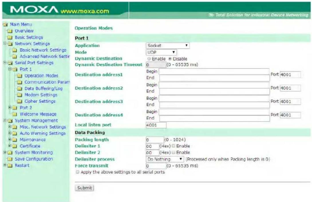
Dynamic Destination (default=disable): When enabled, the destination address and port number are decided by the source (IP address and UDP port number) of the last data received. When the function is enabled, you are NOT able to specify ranges of IP addresses for the serial port to connect to.
Dynamic Destination Timeout (default=0): When the Dynamic Destination function is enabled, the timeout can be set to determine when the NPort will forget the source (IP address and UDP port number) of the last data received. Any other source (IP address and UDP port) will not be able to connect to the NPort until Dynamic Destination Timeout is reached.
Destination address 1 through 4 (default=None): In UDP mode, you may specify up to 4 ranges of IP addresses for the serial port to connect to. At least one destination range must be provided.

ATTENTION
The maximum selectable IP address range is 64 addresses. However, when using multi-unicast, you may enter IP addresses of the form xxx.xxx.xxx.255 in the Begin field. For example, enter 192.127.168.255 to allow the NPort 6000 to broadcast UDP packets to all hosts with IP addresses between 192.127.168.1 and 192.127.168.254.
Local listen port (default=4001): This is the UDP port that the NPort 6000 listens to and that other devices must use to contact the NPort 6000. To avoid conflicts with well-known UDP ports, the default is set to 4001.
Packet length (default=0): The packet length setting refers to the maximum amount of data that is allowed to accumulate in the serial port buffer before sending. At the default of 0 for packet length, no maximum amount is specified and data in the buffer will be sent as specified by the delimiter settings or when the buffer is full. When a packet length between 1 and 1024 bytes is specified, data in the buffer will be sent as soon it reaches the specified length.
Delimiter 1 and Delimiter 2 (default=None): When Delimiter 1 is enabled, the serial port will clear the buffer and send the data to the Ethernet port when a specific character, entered in hex format, is received. A second delimiter character may be enabled and specified in the Delimiter 2 field, so that both characters act as the delimiter to indicate when data should be sent.

ATTENTION
In order to enable a delimiter, the packet length must be set to 0. Delimiter 2 should only be enabled in conjunction with Delimiter 1 and never on its own; otherwise there may be data errors. Even when a delimiter is enabled, the NPort 6000 will still pack and send the data when the amount of data exceeds 1 KB.
Delimiter process (default=Do Nothing): The Delimiter process field determines how the data is handled when a delimiter is received. Delimiter 1 must be enabled for this field to have an effect. If Delimiters 1 and 2 are both enabled, both characters must be received for the delimiter process to take place.
- Do Nothing: Data in the buffer will be transmitted when the delimiter is received.
- Delimiter + 1: Data in the buffer will be transmitted after 1 additional byte is received following the delimiter.
- Delimiter + 2: Data in the buffer will be transmitted after 2 additional bytes are received following the delimiter.
- Strip Delimiter: Data in the buffer is first stripped of the delimiter before being transmitted.
Force transmit (default=0 ms): This parameter defines how large a gap in serial communication the NPort 6000 will allow before packing the serial data in its internal buffer for network transmission.
Pair Connection Mode
Pair Connection mode can be used to remove the 15-meter distance limitation imposed by the RS-232 interface. It establishes a connection between a serial port on one NPort 6000 server and another serial port on another NPort 6000 server. One of the serial ports is connected to the COM port of a PC or another type of computer, such as a handheld PDA that has a serial port. The other serial port is connected to the desired serial device. The two NPort 6000 servers are then connected to each other with a crossover Ethernet cable, and both are connected to the same LAN. In a more advanced setup, the two NPort 6000 servers communicate with each other over a WAN (i.e., through one or more routers). In Pair Connection Mode, both data and modem control signals (but not DCD signals) are transparently transferred between the two NPort 6000 servers.
Pair Connection Master Mode
When using Pair Connection mode, Pair Connection Master mode must be selected as the Operation mode for one of the two serial ports involved, and Pair Connection Slave mode must be selected for the other serial port. In effect, the serial port that is in Pair Connection Master mode will be acting as a TCP client, and the one that is slave mode will be acting as a TCP server. In practice, it does not matter which port is the master and which port is the slave.
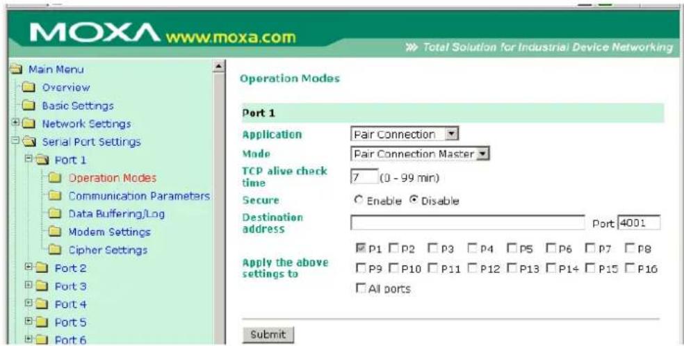
TCP alive check time (default=7 min): This field specifies how long the NPort 6000 will wait for a response to keep-alive packets before closing the TCP connection. The NPort 6000 checks connection status by sending periodic keep-alive packets. If the remote host does not respond to the packet within the time specified in this field, the NPort 6000 will force the existing TCP connection to close. For socket and device control modes, the NPort 6000 will listen for another TCP connection from another host after closing the connection. If TCP alive check time is set to 0, the TCP connection will remain open even if there is no response to the keep-alive packets.
Secure (default= Disable): If you select Enable, data sent through the Ethernet will be encrypted with SSL.

ATTENTION
When establishing a Pair Connection between two serial ports on two different NPort 6000 servers, make sure that if one side is configured for data encryption, the other side is also set up for data encryption (i.e., both are yes or both are no).
Destination IP address: The Pair Connection Master will contact the network host that has the specified IP address. The port will default to 4001. Make sure the port numbers match on both the Pair Connection Master and Slave.
Pair Connection Slave Mode
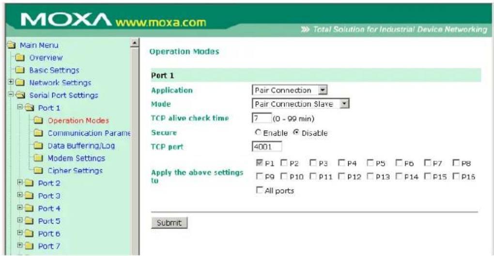
TCP alive check time (default=7 min): This field specifies how long the NPort 6000 will wait for a response to keep-alive packets before closing the TCP connection. The NPort 6000 checks connection status by sending periodic keep-alive packets. If the remote host does not respond to the packet within the time specified in this field, the NPort 6000 will force the existing TCP connection to close. For socket and device control modes, the NPort 6000 will listen for another TCP connection from another host after closing the connection. If TCP alive check time is set to 0, the TCP connection will remain open even if there is no response to the keep-alive packets.
Secure (default=Disable): If you select Enable, data sent through the Ethernet will be encrypted with SSL.
TCP port (default=4001): This is the TCP port number assignment for the serial port on the NPort 6000. It is the port number that the serial port uses to listen to connections and that other devices must use to contact the serial port. To avoid conflicts with well-known TCP ports, the default is set to 4001. Make sure the port numbers match on both the Pair Connection Master and Slave.
Ethernet Modem Mode
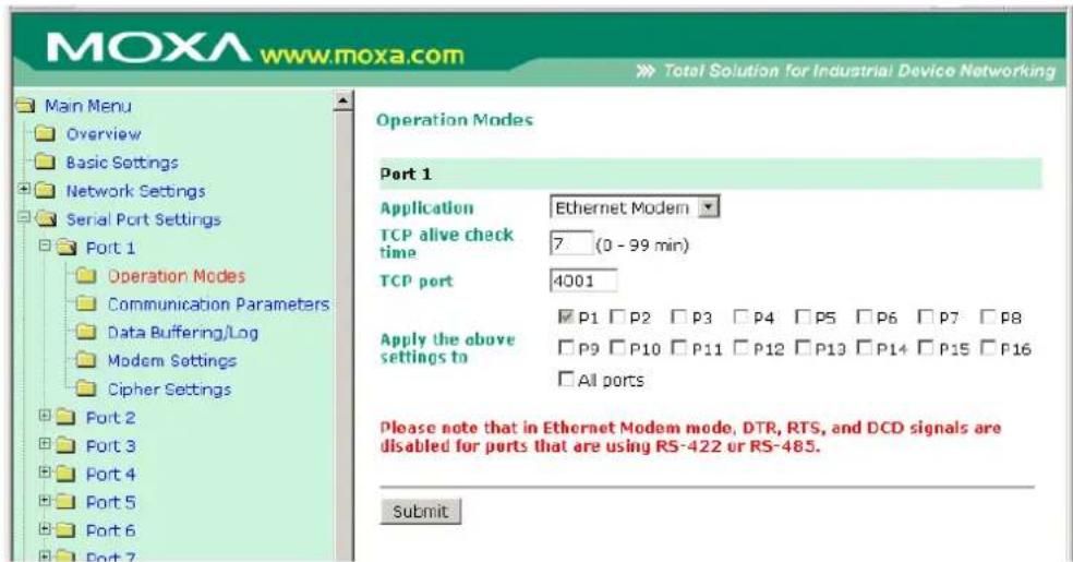
The NPort 6000 accepts the AT command ATD IP address: TCP port (for example, IPv4 : ATD
192.127.168.1:4001 / IPv6 : ADT [fe80::290:e8ff:fe0d:b0fb]:65500 ) from the serial port and then requests a TCP connection from the remote Ethernet Modem or PC. Here IP address is the IP address of the remote Ethernet modem or PC, and TCP port is the TCP port number of the remote Ethernet modem or PC. Once the remote unit accepts this TCP connection, the NPort 6000 will send out the "CONNECT baud" signal via the serial port and then enter data mode.
TCP alive check time (default=7 min): This field specifies how long the NPort 6000 will wait for a response to keep-alive packets before closing the TCP connection. The NPort 6000 checks connection status by sending periodic keep-alive packets. If the remote host does not respond to the packet within the time specified in this field, the NPort 6000 will force the existing TCP connection to close. For socket and device control modes, the NPort 6000 will listen for another TCP connection from another host after closing the connection. If TCP alive check time is set to 0, the TCP connection will remain open even if there is no response to the keep-alive packets.
TCP port (default=4001): This is the TCP port number assignment for the serial port on the NPort 6000. It is the port number that the serial port uses to listen to connections and that other devices must use to contact the serial port. To avoid conflicts with well-known TCP ports, the default is set to 4001.
Dial-in
The NPort 6000 listens for a TCP/IP connection request from the remote Ethernet modem or host. The NPort 6000's response depends on the ATSO value, as follows.
ATS0=0: The NPort 6000 will temporarily accept the TCP connection and then send the "RING" signal out through the serial port. The serial controller must reply with "ATA" within 2.5 seconds to accept the connection request, after which the NPort 6000 enters data mode. If no "ATA" command is received, the NPort 6000 will disconnect after sending three "RING" signals.
ATS0 ≥1: The NPort 6000 will accept the TCP connection immediately and then send the "CONNECT baud" command to the serial port, in which baud represents the baudrate of the NPort 6000's serial port. After that, the NPort 6000 immediately enters data mode.
Dial-out
The NPort 6000 accepts the AT command "ATD IP: TCP port" from the serial port and then requests a TCP connection from the remote Ethernet Modem or PC. Here IP is the IP address of the remote Ethernet modem or PC, and TCP port is the TCP port number of the remote Ethernet modem or PC. Once the remote unit accepts this TCP connection, the NPort 6000 will send out the CONNECT baud" signal via the serial port and then enter data mode.
Disconnection request from local site
When the NPort 6000 is in data mode, the user can initiate disconnection by sending “+ + +” from the local serial port to the NPort 6000. Some applications allow you to directly set the DTR signal to off, which will also initiate disconnection. The NPort 6000 will enter command mode, and after 1 second, you can then enter “ATH” to shut down the TCP connection. The NPort 6000 will return a “NO CARRIER” via the serial port.
NOTE The “+++” command cannot be divided. The “+” character can be changed in register S2, and the guard time, which prefixes and suffixes the “+++” in order to protect the raw data, can be changed in register S12.
Disconnection request from remote site
After the TCP connection has been shut down by the remote Ethernet modem or PC, the NPort 6000 will send the "NO CARRIER" signal via the serial port and then return to command mode.
AT Commands
The NPort 6000 supports the following common AT commands as used with a typical modem:
| No. | AT command | Description | Remarks |
| 1 ATA | Answer manually | ||
| 2 | ATD: | Dial up the IP address : Port No. | |
| 3 ATE | ATE0=Echo OFF | ATE1=Echo ON (default) | |
| 4 ATH | ATH0=On-hook (default) | ATH1=Off-hook | |
| 5 | ATI, ATI0, ATI1, ATI2 | Modem version | reply "OK" only |
| 6 | ATL | Speaker volume option | reply "OK" only |
| 7 | ATM | Speaker control option | reply "OK" only |
| 8 ATO | On line command | ||
| 9 | ATP, ATT | Set Pulse/Tone Dialing mode | reply "OK" only |
| 10 | ATQ0, ATQ1 | Quiet command (default=ATQ0) | |
| 11 | ATSr=n | Change the contents of S register | See "S registers" |
| 12 | ATSr? | Read the contents of S register | See "S registers" |
| 13 | ATV Result code type | ATV0 for digit code,ATV1 for text code (default)0=OK1=connect2=ring3=No carrier4=error | |
| 14 | ATZ | Reset (disconnect, enter command mode and restore the flash settings) | |
| 15 | AT&C | Serial port DCD controlAT&C0=DCD always onAT&C1=DTE detects connection by DCD on/off (default) | |
| 16 | AT&F | Restore manufacturer's settings | |
| 17 | AT&G | Select guard time | reply "OK" only |
| 18 | AT&R | Serial port RTS option command | reply "OK" only |
| 19 | AT&S | Serial port DSR control | reply "OK" only |
| 20 | AT&V | View settings | |
| 21 | AT&W | Write current settings to flash for next boot up | |
S Registers
| No. | S Register | Description & default value | Remarks |
| 1 | S0 | Ring to auto-answer (default=0) | |
| 2 | S1 | Ring counter (always=0) | no action applied |
| 3 | S2 | Escape code character (default=43 ASCII “+”) | |
| 4 S3 | Return character (default=13 ASCII) | ||
| 5 S4 | Line feed character (default=10 ASCII) | ||
| 6 S5 | Backspace character (default= 8 ASCII) | ||
| 7 | S6 | Wait time for dial tone (always=2, unit=sec) | no action applied |
| 8 | S7 | Wait time for carrier (default=3, unit=sec) | |
| 9 | S8 | Pause time for dial delay (always=2, unit=sec) | no action applied |
| 10 | S9 | Carrier detect response time (always=6, unit 1/10 sec) | no action applied |
| 11 | S10 | Delay for hang up after carrier (always=14, unit 1/10 sec) | no action applied |
| 12 | S11 | DTMF duration and spacing (always=100 ms) | no action applied |
| 13 | S12 | Escape code guard time (default=50, unit 1/50 sec) to control the idle time for “+++” |
Terminal Applications
Terminal ASCII (TERM_ASC)
![MOXA www.moxa.com Main Menu Overview Basic Settings Network Settings Serial Port Settings Port 1 Operation Modes Communication Parameters Data Buffering/Log Modern Settings Cipher Settings Port 2 Port 3 Port 4 Port 5 Port 6 Port 7 Port 8 Welcome Message System Management System Monitoring Sava Configuration Restart Operation Modes Port 1 Application Terminal Mode Terminal (TERM_ASC) TCP alive check time 7 [0 - 99 min] Inactivity time 0 [0 - 99 min] Auto-link protocol None Primary host address Secondary host address Talent TCP port 23 Terminal Terminal type ans Max. sessions d Change session "T Quit "E Break Interrupt Authentication type None Try next type on authentication denied Enable Disable Automatic Login Auto login prompt login: Password prompt Login user name: Login password: P1 P2 P3 P4 P5 P6 P7 P8 Total Solutions for Industrial Device Networking](/content/2026/06/1269850/images/ed33ee4cbfea1af12bf6fe942c9b7f41e3bfda7a13b6f1bbf867c80469199c51.jpg)
Authentication type (default=None): This field allows you to configure the method used, if any, to verify a user's ID and authorization.
| Option Description | |
| Local | Verify the ID against the NPort 6000 User Table. |
| RADIUS | Verify the ID against the external RADIUS server. |
| RADIUS - Local | Radius authentication is tried first, switching to Local if unsuccessful. |
| Local - RADIUS | Authentication is performed locally first, switching to Radius if unsuccessful. |
| TACACS+ | Verify the ID against the external TACACS+ server. |
| TACACS+ - Local | TACACS+ authentication is tried first, switching to Local if unsuccessful. |
| Local - TACACS+ | Authentication is performed locally first, switching to Radius if unsuccessful. |
| None | Authentication is not required. |
Try next type on authentication denied (default=Disable): The field enables or disables the system to try next type on first authentication denied.
TCP alive check time (default=7 min): This field specifies how long the NPort 6000 will wait for a response to keep-alive packets before closing the TCP connection. The NPort 6000 checks connection status by sending periodic keep-alive packets. If the remote host does not respond to the packet within the time specified in this field, the NPort 6000 will force the existing TCP connection to close. For socket and device control modes, the NPort 6000 will listen for another TCP connection from another host after closing the connection. If TCP alive check time is set to 0, the TCP connection will remain open even if there is no response to the keep-alive packets.
Inactivity time (default=0 min): This field specifies how long the NPort 6000 will wait for incoming and outgoing data through the serial port before closing the TCP connection. The TCP connection is closed if there is no incoming or outgoing data through the serial port for the specified Inactivity time. If this field is set to 0, the TCP connection is kept active until a connection close request is received.

ATTENTION
Inactivity time should at least be set larger than that of Force transmit time. To prevent the unintended loss of data due to the session being disconnected, it is highly recommended that this value is set large enough such that the intended data transfer is completed.
Auto-Link Protocol: If this field is set to None, the NPort 6000 will not connect to the host automatically. If Auto-Link Protocol is set to Telnet or Rlogin, the NPort 6000 will connect to the host automatically using the specified protocol.
Primary and Secondary host address: If specified, the fields designate permanent hosts to which the terminal will always be connected.
Telnet TCP port (default=23): By default, the Telnet TCP port number is set to 23, which is the default TCP port number for Telnet.
Terminal type (default=ansi): Some older terminal applications may require that the terminal type be transmitted before the connection can be established. You may need to refer to the server's documentation to determine the appropriate terminal type. For most applications, this setting will be unnecessary and will have no effect
Max. Sessions (default=4): This setting allows you to configure the maximum. number of sessions allowed for the serial port.
Change Session (default=(^T)0x14): This field defines the quick key to change a session.
Quit (default=(^E)0x05): This field defines the quick key to quit a session.
Break: This field defines the quick key to send a break signal.
Interrupt: This field defines the quick key for program termination.
Auto-login prompt (default=ogin:)
Password prompt (default=password:)
Login user name: Enter the terminal login ID here.
Login password: Enter the password for the terminal login here.
Terminal BIN (TERM\_BIN)
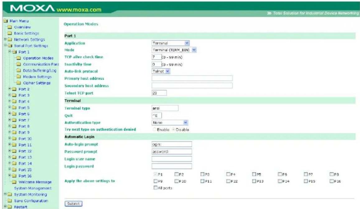
Terminal Binary mode can be used to transfer files with XMODEM or ZMODEM. You are only allowed to open one terminal session at a time when in Terminal Binary mode.
TCP alive check time (default=7 min): This field specifies how long the NPort 6000 will wait for a response to keep-alive packets before closing the TCP connection. The NPort 6000 checks connection status by sending periodic keep-alive packets. If the remote host does not respond to the packet within the time specified in this field, the NPort 6000 will force the existing TCP connection to close. For socket and device control modes, the NPort 6000 will listen for another TCP connection from another host after closing the connection. If TCP alive check time is set to 0, the TCP connection will remain open even if there is no response to the keep-alive packets.
Inactivity time (default=0 min): This field specifies how long the NPort 6000 will wait for incoming and outgoing data through the serial port before closing the TCP connection. The TCP connection is closed if there is no incoming or outgoing data through the serial port for the specified Inactivity time. If this field is set to 0, the TCP connection is kept active until a connection close request is received.

ATTENTION
Inactivity time should at least be set larger than that of Force transmit time. To prevent the unintended loss of data due to the session being disconnected, it is highly recommended that this value is set large enough so that the intended data transfer is completed.
Auto-Link Protocol: If this field is set to None, the NPort 6000 will not connect to the host automatically. If Auto-Link Protocol is set to Telnet or Rlogin, the NPort 6000 will connect to the host automatically using the specified protocol.
Primary and Secondary host address: If specified, the fields designate permanent hosts to which the terminal will always be connected.
Telnet TCP port (default=23): By default, the Telnet TCP port number is set to 23, which is the default TCP port number for Telnet.
Terminal type (default=ansi): Some older terminal applications may require that the terminal type be transmitted before the connection can be established. You may need to refer to the server's documentation to determine the appropriate terminal type. For most applications, this setting will be unnecessary and will have no effect
Quit (default=(^E)0x05): This field configures the quick key used to disconnect the link between the current terminal session and the remote host. It is not necessary for binary communication.
Authentication type (default=None): This field allows you to configure the method used, if any, to verify a user's ID and authorization.
| Option Description | |
| Local | Verify the ID against the NPort 6000 User Table. |
| RADIUS | Verify the ID against the external RADIUS server. |
| RADIUS - Local | Radius authentication is tried first, switching to Local if unsuccessful. |
| Local - RADIUS | Authentication is performed locally first, switching to Radius if unsuccessful. |
| TACACS+ | Verify the ID against the external TACACS+ server. |
| TACACS+ - Local | TACACS+ authentication is tried first, switching to Local if unsuccessful. |
| Local - TACACS+ | Authentication is performed locally first, switching to Radius if unsuccessful. |
| None | Authentication is not required. |
Try next type on authentication denied (default=Disable): The field enables or disables the system to try next type on first authentication denied.
Auto-login prompt (default=ogin:)
Password prompt (default=assword:)
Login user name: Enter the terminal login ID here.
Login password: Enter the password for the terminal login here.
SSH
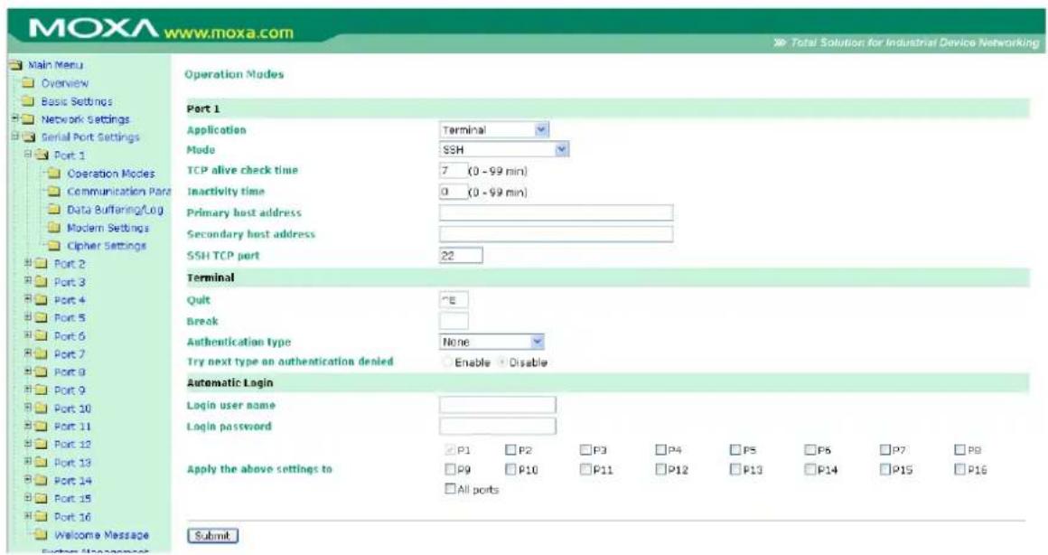
TCP alive check time (default=7 min): The TCP connection will be closed if there is no TCP activity for the specified amount of time. If this is set to 0, the TCP connection will remain open even if the connection remains idle. For socket and device control modes, the NPort 6000 will start listening for another TCP connection from another host after the connection is closed for being idle.
Inactivity time (default=0 min): This field specifies how long the NPort 6000 will wait for incoming and outgoing data through the serial port before closing the TCP connection. The TCP connection is closed if there is no incoming or outgoing data through the serial port for the specified Inactivity time. If this field is set to 0, the TCP connection is kept active until a connection close request is received.

ATTENTION
Inactivity time should at least be set larger than that of Force transmit time. To prevent the unintended loss of data due to the session being disconnected, it is highly recommended that this value is set large enough so that the intended data transfer is completed.
Primary and Secondary host address: If specified, the fields designate permanent hosts to which the terminal will always be connected.
SSH TCP port (default=22): By default, the SSH TCP port number is set to 22, which is the default SSH port number.
Quit (default=(^E)0x05): This field configures the quick key used to disconnect the link between the current terminal session and the remote host. For binary communication, it is unnecessary to define the quit key.
Break: This field defines the Host key for sending the break signal. For binary communication, it is unnecessary to define the break key.
Authentication type (default=None): This field allows you to configure the method used, if any, to verify a user's ID and authorization.
| Option Description | |
| Local | Verify the ID against the NPort 6000 User Table. |
| RADIUS | Verify the ID against the external RADIUS server. |
| RADIUS - Local | Radius authentication is tried first, switching to Local if unsuccessful. |
| Local - RADIUS | Authentication is performed locally first, switching to Radius if unsuccessful. |
| TACACS+ | Verify the ID against the external TACACS+ server. |
| TACACS+ - Local | TACACS+ authentication is tried first, switching to Local if unsuccessful. |
| Local - TACACS+ | Authentication is performed locally first, switching to Radius if unsuccessful. |
| None | Authentication is not required. |
Try next type on authentication denied (default=Disable): The field enables or disables the system to try next type on first authentication denied.
Login user name: Enter the terminal login ID here.
Login password: Enter the password for the terminal login here.
Reverse Terminal Applications
Reverse Telnet Mode
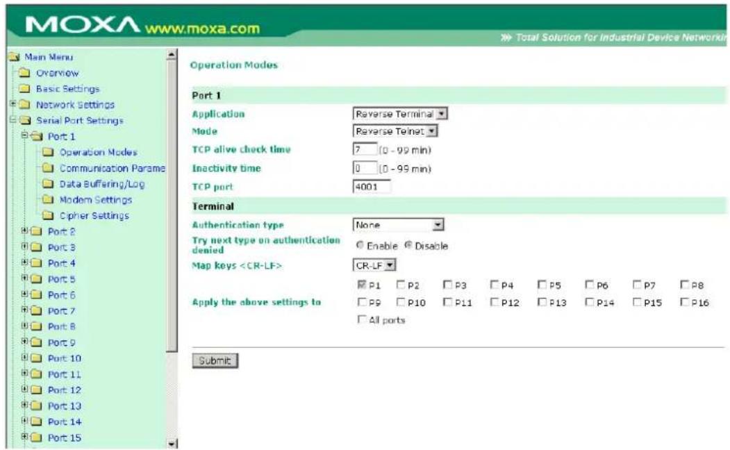
TCP alive check time (default=7 min): This field specifies how long the NPort 6000 will wait for a response to keep-alive packets before closing the TCP connection. The NPort 6000 checks connection status by sending periodic keep-alive packets. If the remote host does not respond to the packet within the time specified in this field, the NPort 6000 will force the existing TCP connection to close. For socket and device control modes, the NPort 6000 will listen for another TCP connection from another host after closing the connection. If TCP alive check time is set to 0, the TCP connection will remain open even if there is no response to the keep-alive packets.
Inactivity time (default=0 min): This field specifies the idle time setting for auto-disconnection. A setting of 0 min. will cause the port to remain connected even if idle.
TCP port (default=4001): This is the TCP port number assignment for the serial port on the NPort 6000. It is the port number that the serial port uses to listen to connections and that other devices must use to contact the serial port. To avoid conflicts with well-known TCP ports, the default is set to 4001.
Authentication type (default=None): This field allows you to configure the method used, if any, to verify a user's ID and authorization.
| Option Description | |
| Local | Verify the ID against the NPort 6000 User Table. |
| RADIUS | Verify the ID against the external RADIUS server. |
| RADIUS - Local | Radius authentication is tried first, switching to Local if unsuccessful. |
| Local - RADIUS | Authentication is performed locally first, switching to Radius if unsuccessful. |
| TACACS+ | Verify the ID against the external TACACS+ server. |
| TACACS+ - Local | TACACS+ authentication is tried first, switching to Local if unsuccessful. |
| Local - TACACS+ | Authentication is performed locally first, switching to Radius if unsuccessful. |
| None | Authentication is not required. |
Try next type on authentication denied (default=Disable): The field enables or disables the system to try next type on first authentication denied.
Map keys
| Option Description | |
| carriage return + line feed (i.e., the cursor will jump to the next line, and return to the first character of the line) | |
| carriage return (i.e., the cursor will return to the first character of the line) | |
| line feed (i.e., the cursor will jump to the next line, but not move horizontally) |
Reverse SSH Mode
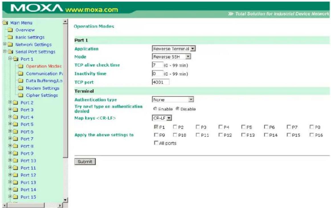
TCP alive check time (default=7 min): This field specifies how long the NPort 6000 will wait for a response to keep-alive packets before closing the TCP connection. The NPort 6000 checks connection status by sending periodic keep-alive packets. If the remote host does not respond to the packet within the time specified in this field, the NPort 6000 will force the existing TCP connection to close. For socket and device control modes, the NPort 6000 will listen for another TCP connection from another host after closing the connection. If TCP alive check time is set to 0, the TCP connection will remain open even if there is no response to the keep-alive packets.
Inactivity time (default=0 min): This field specifies the idle time setting for auto-disconnection. A setting of 0 min. will cause the port to remain connected even if idle.
TCP port (default=4001): This is the TCP port number assignment for the serial port on the NPort 6000. It is the port number that the serial port uses to listen to connections, and that other devices must use to contact the serial port. To avoid conflicts with well known TCP ports, the default is set to 4001.
Each of NPort 6000's serial ports is mapped to a TCP port. To avoid conflicts with other TCP ports, set port numbers to 4001 for port 1, 4002 for port 2, etc.
Authentication type (default=None): This field allows you to configure the method used, if any, to verify a user's ID and authorization.
| Option Description | |
| Local | Verify the ID against the NPort 6000 User Table. |
| RADIUS | Verify the ID against the external RADIUS server. |
| RADIUS - Local | Radius authentication is tried first, switching to Local if unsuccessful. |
| Local - RADIUS | Authentication is performed locally first, switching to Radius if unsuccessful. |
| TACACS+ | Verify the ID against the external TACACS+ server. |
| TACACS+ - Local | TACACS+ authentication is tried first, switching to Local if unsuccessful. |
| Local - TACACS+ | Authentication is performed locally first, switching to Radius if unsuccessful. |
| None | Authentication is not required. |
Try next type on authentication denied (default=Disable): The field enables or disables the system to try next type on first authentication denied.
Map keys
| Option Description | |
| carriage return + line feed (i.e., the cursor will jump to the next line, and return to the first character of the line) | |
| carriage return (i.e., the cursor will return to the first character of the line) | |
| line feed (i.e., the cursor will jump to the next line, but not move horizontally) |
Printer Applications
RAW PRN Mode
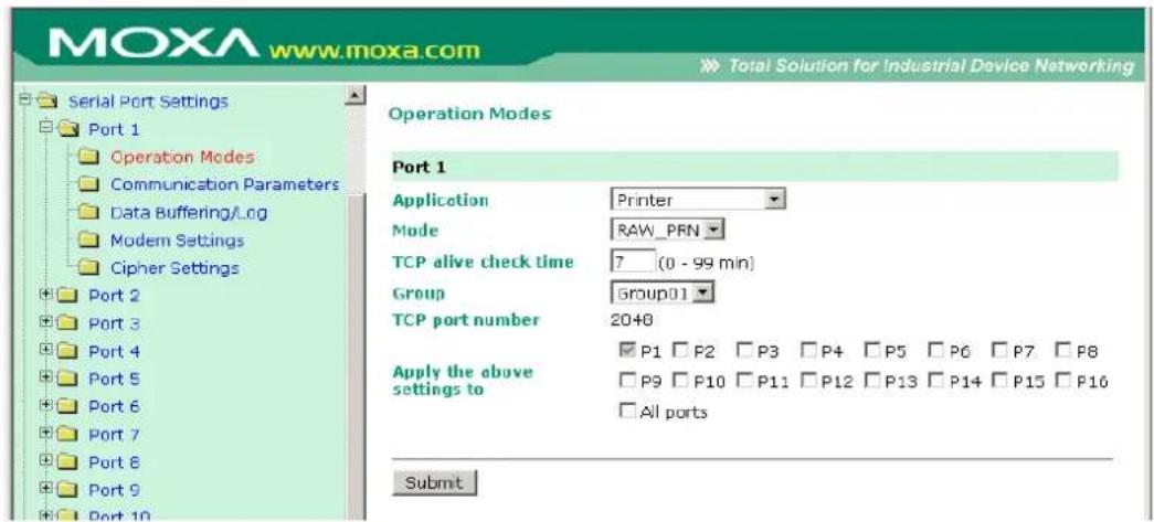
TCP alive check time (default=7 min): This field specifies how long the NPort 6000 will wait for a response to keep-alive packets before closing the TCP connection. The NPort 6000 checks connection status by sending periodic keep-alive packets. If the remote host does not respond to the packet within the time specified in this field, the NPort 6000 will force the existing TCP connection to close. For socket and device control modes, the NPort 6000 will listen for another TCP connection from another host after closing the connection. If TCP alive check time is set to 0, the TCP connection will remain open even if there is no response to the keep-alive packets.
Group (default= Group 01): This field groups printers attached to different ports. When printing requests are sent a group of printers, all printers in that group will share the printing load. For example, setting the NPort 6000's serial ports 1, 3, and 6 to Group 01 will allow the printers attached to these three ports to act essentially as one printer.
TCP port number: This field is automatically filled in by the NPort 6000 and cannot be set by the user. The host uses this value to determine the Group to which the printer attached to this serial port belongs. Groups 01 to 06 are mapped to ports 2048 to 2063 respectively.
LPD PRN Mode
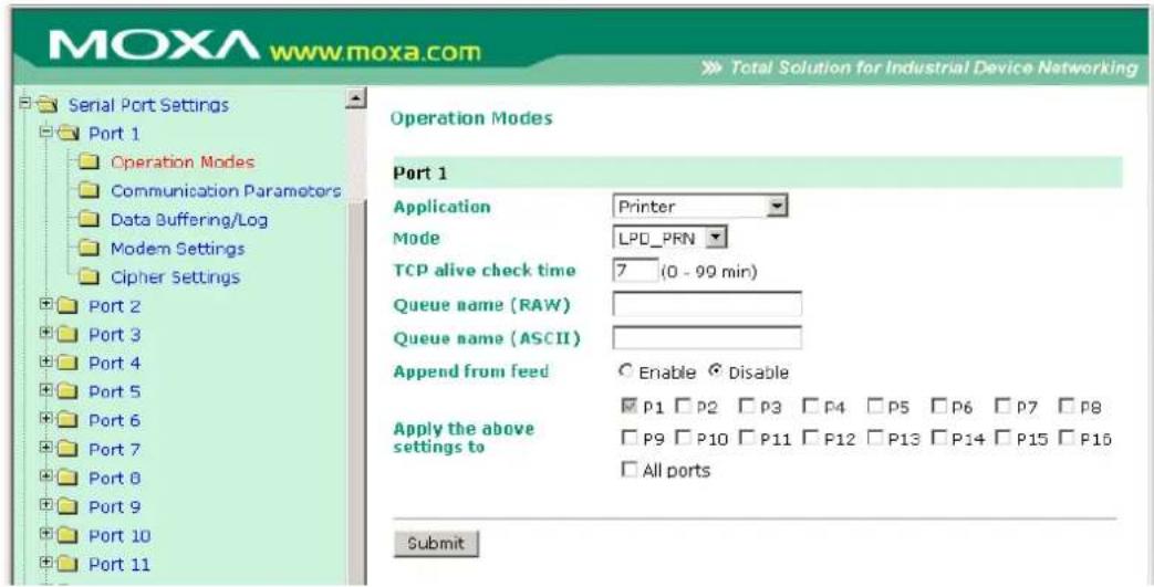
TCP alive check time (default=7 min): This field specifies how long the NPort 6000 will wait for a response to keep-alive packets before closing the TCP connection. The NPort 6000 checks connection status by sending periodic keep-alive packets. If the remote host does not respond to the packet within the time specified in this field, the NPort 6000 will force the existing TCP connection to close. For socket and device control modes, the NPort 6000 will listen for another TCP connection from another host after closing the connection. If TCP alive check time is set to 0, the TCP connection will remain open even if there is no response to the keep-alive packets.
Queue name (RAW): This field optionally specifies the print queue's name (in RAW mode)
Queue name (ASCII): This field optionally specifies the print queue's name (in ASCII mode)
Append from feed (default=Disable): This field instructs the port to send a line feed in between print jobs, rather than continue where the last print job left off. This may be necessary for some applications.
Dial In/ Out Applications
PPP Mode
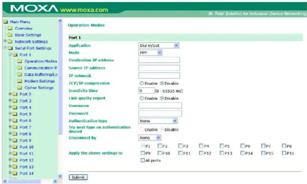
PPP provides standard PPP service for both dial-in and dial-out.
Destination IP address: This is the IP address of the remote dial-in/ dial-out server.
Source IP address: The Source IP address is IP address assigned to this serial port.
IP netmask: The IP netmask defines the netmask, also known as the subnet mask, for the PPP connection
TCP/IP compression (default=Disable): The setting of this field depends on whether the remote user's application requests compression.
Inactivity time (default=0 ms): This field specifies the idle time setting for auto-disconnection. A setting of 0 ms will cause the port to remain connected even if idle.
Link quality report (default=Disable): Setting this field to Enable allows the NPort 6000 to disconnect a connection if the link noise exceeds a certain threshold.
Username: This is the dial-out user ID account.
Password: This is the dial-out user password.
Authentication type (default=None): This field allows you to configure the method used, if any, to verify a user's ID and authorization.
| Option Description | |
| Local | Verify the ID against the NPort 6000 User Table. |
| RADIUS | Verify the ID against the external RADIUS server. |
| RADIUS-Local | Radius authentication is tried first, switching to Local if unsuccessful. |
| Local-RADIUS | Authentication is performed locally first, switching to Radius if unsuccessful |
| TACACS+ | Verify the ID against the external TACACS+ server. |
| TACACS+-Local | TACACS+ authentication is tried first, switching to Local if unsuccessful. |
| Local-TACACS+ | Authentication is performed locally first, switching to Radius if unsuccessful |
| None | Authentication is not required. |
Try next type on authentication denied (default=Disable): The field enables or disables the system to try next type on first authentication denied.
Disconnect by (default=None): If this field is set as DCD-off, the connection will be disconnected when the DCD signal is off. If this field is set as DSR-off, the connection will be disconnected when the DSR signal is off.
PPPD Mode
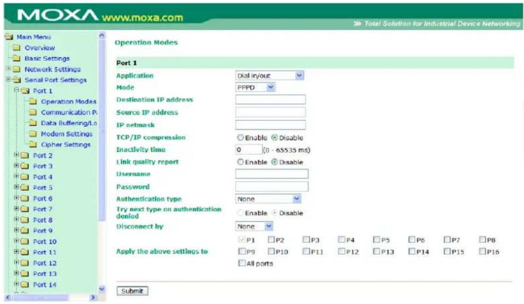
PPPD (PPP on demand) is used for dial-in services, since it provides PPP services only when receiving a request from a remote PC.
Destination IP address: This is the IP address of the remote dial-in/ dial-out server.
Source IP address: The Source IP address is IP address assigned to this serial port.
IP netmask: The IP netmask defines the netmask, also known as the subnet mask, for the PPP connection
TCP/IP compression (default=Disable): The setting of this field depends on whether the remote user's application requests compression.
Inactivity time (default=0 ms): This field specifies the idle time setting for auto-disconnection. A setting of 0 ms will cause the port to remain connected even if idle.
Link quality report (default=Disable): Setting this field to Enable allows the NPort 6000 to disconnect a connection if the link noise exceeds a certain threshold.
Username: This is the dial-out user ID account.
Password: This is the dial-out user password.
Authentication type (default=None): This field allows you to configure the method used, if any, to verify a user's ID and authorization.
| Option Description | |
| Local | Verify the ID against the NPort 6000 User Table. |
| RADIUS | Verify the ID against the external RADIUS server. |
| RADIUS-Local | Radius authentication is tried first, switching to Local if unsuccessful. |
| Local-RADIUS | Authentication is performed locally first, switching to Radius if unsuccessful |
| TACACS+ | Verify the ID against the external TACACS+ server. |
| TACACS+-Local | TACACS+ authentication is tried first, switching to Local if unsuccessful. |
| Local-TACACS+ | Authentication is performed locally first, switching to Radius if unsuccessful |
| None | Authentication is not required. |
Try next type on authentication denied (default=Disable): The field enables or disables the system to try next type on first authentication denied.
Disconnect by (default=None): If this field is set as DCD-off, the connection will be disconnected when the DCD signal is off. If this field is set as DSR-off, the connection will be disconnected when the DSR signal is off.
SLIP Mode
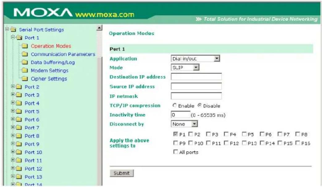
SLIP provides standard SLIP service for both dial-in and dial-out.
Destination IP address: This is the IP address of the remote dial-in/ dial-out server.
Source IP address: The Source IP address is IP address assigned to this serial port.
IP netmask: The IP netmask defines the netmask, also known as the subnet mask, for the SLIP connection
TCP/IP compression (default=No): The setting of this field depends on whether the remote user's application requests compression.
Inactivity time (default=0 ms): This field specifies the idle time setting for auto-disconnection. A setting of 0 ms will cause the port to remain connected even if idle.
Disconnect by (default=None): If this field is set as DCD-off, the connection will be disconnected when the DCD signal is off. If this field is set as DSR-off, the connection will be disconnected when the DSR signal is off.
SLIPD Mode
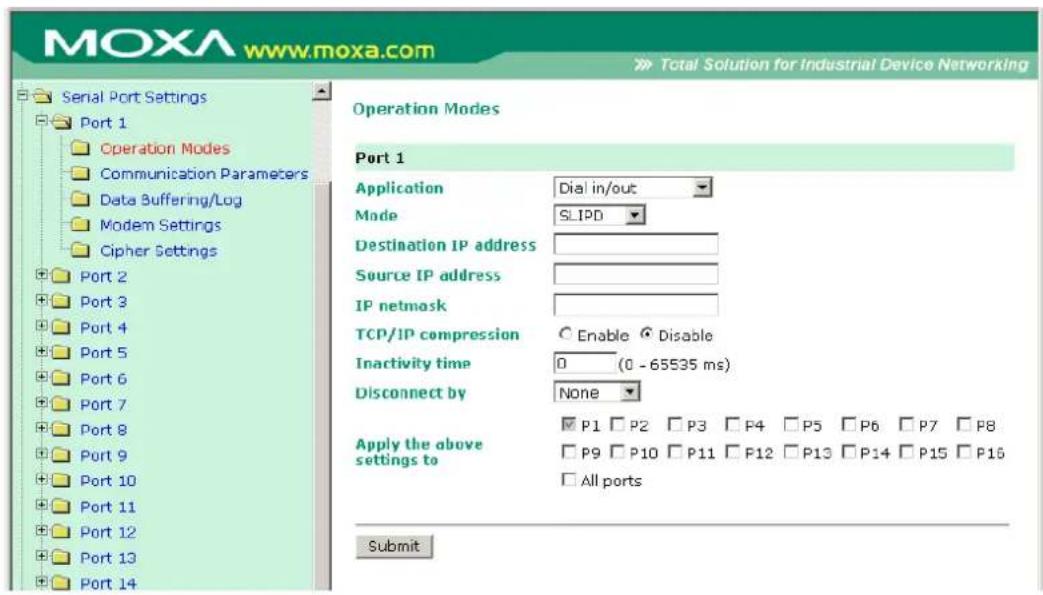
SLIPD (SLIP on demand) is used for dial-in services, since it provides SLIP services only when receiving a request from a remote PC.
Destination IP address: This is the IP address of the remote dial-in/ dial-out server.
Source IP address: The Source IP address is IP address assigned to this serial port.
IP netmask: The IP netmask defines the netmask, also known as the subnet mask, for the SLIP connection
TCP/IP compression (default=No): The setting of this field depends on whether the remote user's application requests compression.
Inactivity time (default=0 ms): This field specifies the idle time setting for auto-disconnection. A setting of 0 ms will cause the port to remain connected even if idle.
Disconnect by (default=None): If this field is set as DCD-off, the connection will be disconnected when the DCD signal is off. If this field is set as DSR-off, the connection will be disconnected when the DSR signal is off.
Dynamic Mode
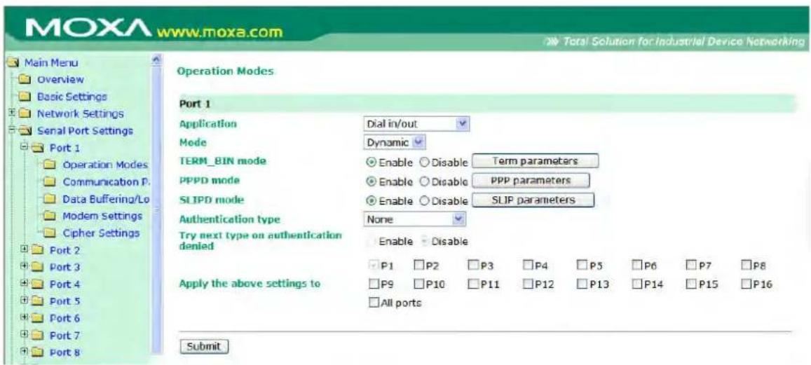
Dynamic mode integrates PPPD, SLIPD, and Terminal dial-in services. Dynamic mode automatically detects which remote connection mode is being used, and provides corresponding services. You can individually enable/disable PPP/SLIP/Terminal services by selecting Yes or No next to the corresponding option. Yes will enable that type of service; No will disable it.
Authentication type (default=None): This field allows you to configure the method used, if any, to verify a user's ID and authorization.
| Option Description | |
| Local | Verify the ID against the NPort 6000 User Table. |
| RADIUS | Verify the ID against the external RADIUS server. |
| RADIUS-Local | Radius authentication is tried first, switching to Local if unsuccessful. |
| Local-RADIUS | Authentication is performed locally first, switching to Radius if unsuccessful |
| TACACS+ | Verify the ID against the external TACACS+ server. |
| TACACS+-Local | TACACS+ authentication is tried first, switching to Local if unsuccessful. |
| Local-TACACS+ | Authentication is performed locally first, switching to Radius if unsuccessful |
| None | Authentication is not required. |
Try next type on authentication denied (default=Disable): The field enables or disables the system to try next type on first authentication denied.
Disabled Mode
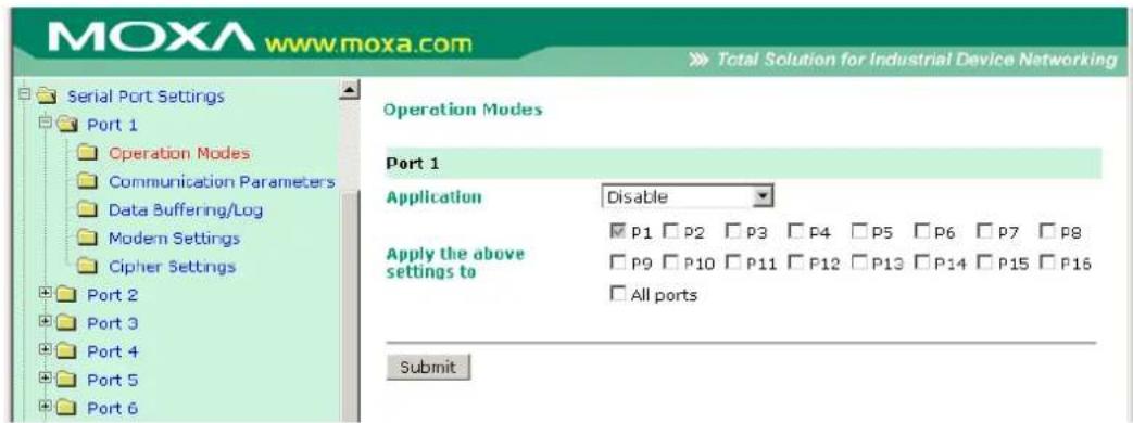
When the Application is set to Disable, the relevant port will be disabled.
In this chapter, we describe additional serial port settings on the NPort 6000. The same configuration options are also available through the Telnet and serial console.
The following topics are covered in this chapter:
□ Port Communication Parameters
Serial Parameters
□ Port Data Buffering/ Log
□ Port Modem Settings
□ Port Cipher Settings
□ Welcome Message
Port Communication Parameters
![MOXA www.moxa.com Total Solution for Industrial Device Networking Serial Port Settings Port 1 Operation Modes Communication Parameters Data Buffering/Log Modem Settings Cipher Settings Port 2 Port 3 Port 4 Port 5 Port 6 Port 7 Port 8 Port 9 Port 10 Port 11 Port 12 Port 13 Port 14 Communication Parameters Port 1 Port alias Serial Parameters Baud rate [Hint] 115200 Data bits 8 Stop bits 1 Parity None Flow control RTS/CTS FIFO Enable Disable Interface RS-232 Apply the above settings to P1 P2 P3 P4 P5 P6 P7 P8 P9 P10 P11 P12 P13 P14 P15 P16 All ports Submit](/content/2026/06/1269850/images/aad03f312baa3e4f9bf267aeeb8df2c60386e2c6768ac0c3e34c43449cd5e5e5.jpg)
Port alias: This optional field allows you to assign an alias to a port for easier identification.
Serial Parameters

ATTENTION
The serial parameters for the each serial port on the NPort 6000 should match the parameters used by the connected serial device. You may need to refer to your serial device's user's manual to determine the appropriate serial communication parameters.
Baudrate (default=115200 bps): This field configures the port's baudrate. Select one of the standard baudrates from the dropdown box, or select Other and then type the desired baudrate in the input box.

ATTENTION
If the port requires a special baudrate that is not listed, such as 500000 bps, you may can select the Other option and enter the desired baudrate into the text box. The NPort 6000 will automatically calculate the closest supported baudrate. The margin for error will be less than 1.7% for all baudrates under 921600 bps.
Data bits (default=8): This field configures the data bits parameter. Note: If data bits is set to 5 bits, stop bits will automatically be set to 2 bits.
Stop bits (default=1): This field configures the stop bits parameter. Note: If data bits is set to 5 bits, stop bits will automatically be set to 1.5 bits.
Parity (default=None): This field configures the parity parameter.
Flow control (default=RTS/CTS): This field configures the flow control type, including RTS/CTS, DTR/DSR, Xon/Xoff, RTS Toggle* and None.
*The RTS Toggle function is used for RS-232 mode only. This flow control mechanism is achieved by toggling the RTS pin in the transmission direction. When activated, data will be sent after the RTS pin is toggled ON for the set time interval. After data transmission is finished, the RTS pin will toggle OFF for the set time interval. The preset time interval of toggling ON and OFF the RTS signal is denoted in the figure below. RTS Toggle is not supported under RFC2217 mode.
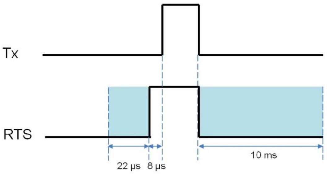
other
| Signal | Duration (ms) | |--------|---------------| | Tx | 22 | | RTS | 8 | | Tx | 10 | | RTS | 10 |FIFO (default=Enable): This field enables or disables the 128-byte FIFO buffer. The NPort 6000 provides FIFO buffers for each serial port, for both the Tx and Rx signals. Note, however, that you should disable the port's FIFO setting if the attached serial device does not have a FIFO buffer of its own. This is because a serial device that does not have its own buffer may not be able to keep up with data sent from the NPort's FIFO buffer.
Interface (default=RS-232): You may configure the serial interface to RS-232, RS-422, RS-485 2-wire, or RS-485 4-wire.
Port Data Buffering/ Log
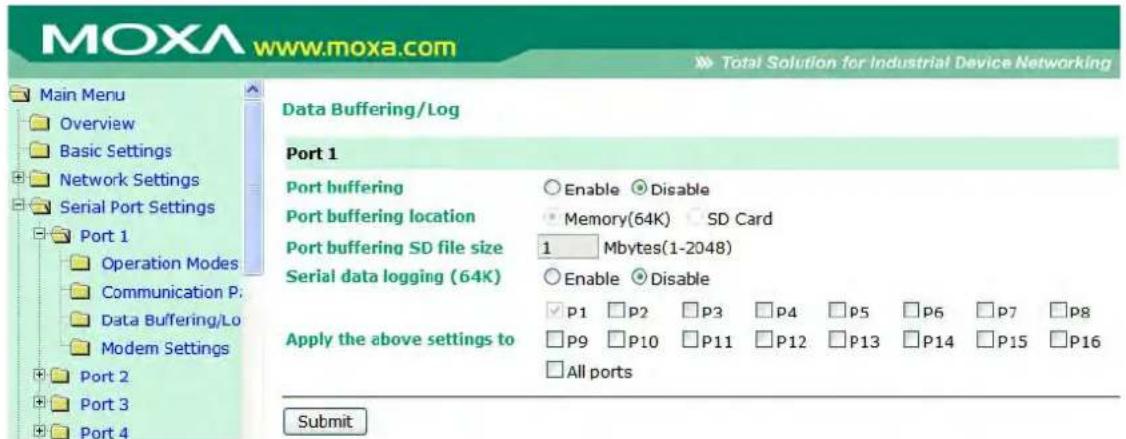
The NPort 6000 supports port buffering to prevent the loss of serial data when the Ethernet connection is down. Port buffering can be used in TCP Server mode, TCP Client mode, and Pair Connection mode. For other modes, the port-buffering settings will have no effect.
Port buffering enable (default=Disable): You may enable port buffering by setting this field to Enable.
Port buffering location (default=Memory(64K)): If port buffering is desired, use this setting to configure whether the buffer is located in the system memory or in an optional installed SD card. Install and use an SD card if a buffer size greater than 64 KB is desired. Note that optional SD cards are not supported on the NPort 6150.
Port buffering SD file size (default=1 Megabyte): Use this field to configure the size of the port buffer if you have configured it to reside on an SD card. Note that optional SD cards are not supported on the NPort 6150.
Serial data logging enable (default=Disable): If this field is set to Enable, the NPort 6000 will store data logs on the system RAM for all serial ports. Note that this data is not saved when the NPort 6000 is powered off. Each serial port is allotted 64 KB to store that port's log file.
Port Modem Settings
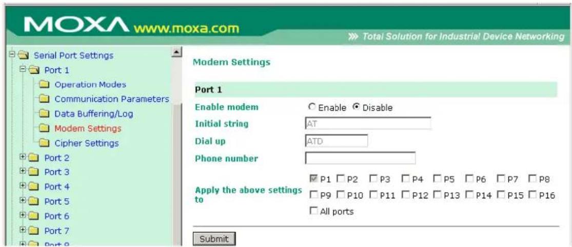
Modem settings are used for the Dial In/Out modes. These settings will have no effect on ports configured for other modes.
Enable modem (default=Disable)
Initial string: Use this field to configure the initial string that the modem will use to establish the connection. For example, AT&S0=1 for auto-answer.
Dial up: Use this field to configure the modem's Dial-up AT command string.
Phone number: Use this field to configure the number that the user uses to dial out.
Port Cipher Settings
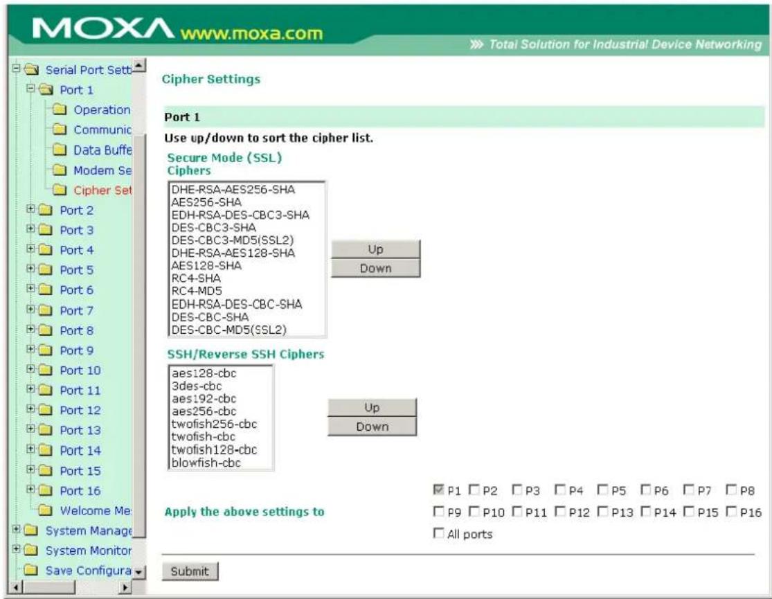
Serial Port Settings → Port N → Cipher Settings
Used to choose cipher priority for SSL and SSH to build secure connections. The Secure Mode(SSL) Ciphers are for when Secure mode is be selected. The SSH/ Reverse SSH Ciphers are only for SSH terminals and Reverse SSH terminals.
Welcome Message
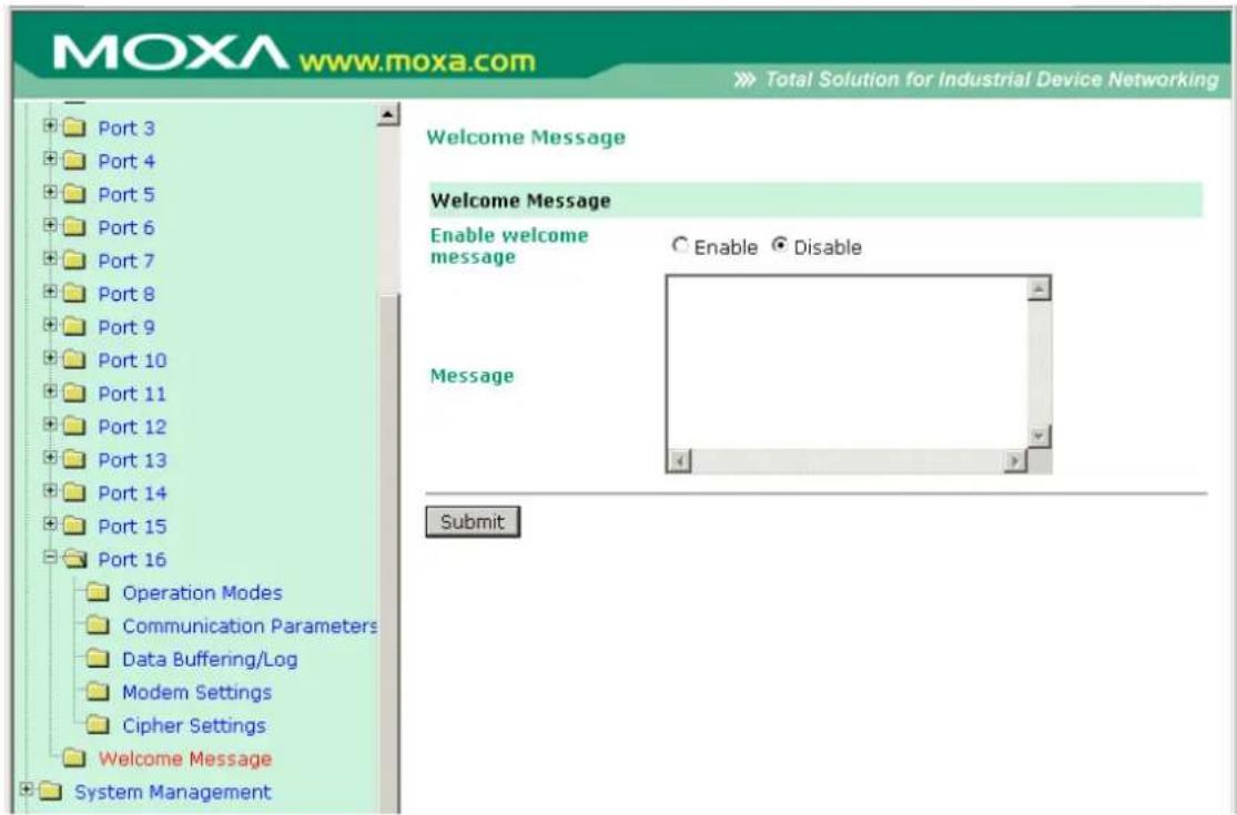
You can enable and enter a welcome message to greet dial-in or terminal users. For ports configured for other modes, the welcome message will not apply.
In this chapter, we describe additional server settings on the NPort 6000. The same configuration options are also available through the Telnet and serial console.
The following topics are covered in this chapter:
□ Misc. Network Settings
▶ Accessible IP List
SNMP Agent Settings
DDNS
Host Table
User Table
▶ Authentication Server
System Log Settings
Configure the Remote Log Server
□ Auto Warning Settings
Event Settings
Serial Event Settings
E-mail Alert
SNMP Trap
□ Maintenance
Console Setting
Ping
➢ Firmware Upgrade
Configuration Import/Export
Load Factory Defaults
Change Password
□ Certificate
Ethernet SSL Certificate Import
▶ Certificate/Key Delete
□ System Monitoring
Serial to Network Connections
Serial Port Status
Serial Port Error Count
Serial Port Settings
Serial Cipher Usage Status
▶ Network Connections
Network Statistics
Network Module
Serial Data Log
System Log
Routing
PPP-Trace
Dout State (for 6450/6600)
□ Save Configuration
□ Restart
▶ Restart System
Restart Ports
Misc. Network Settings
Accessible IP List
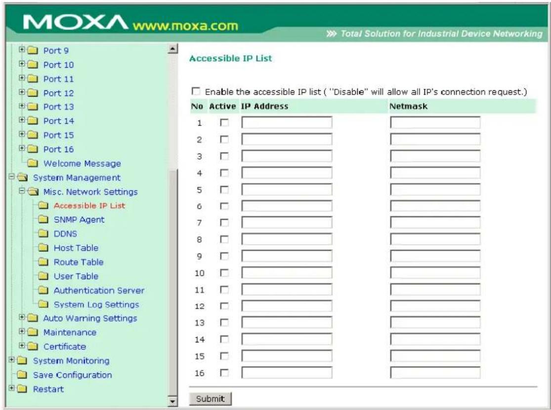
The NPort 6000 uses an IP address-based filtering method to control access to its serial ports.
The Accessible IP list allows you restrict network access to the NPort 6000. Access is controlled by IP address. When the accessible IP list is enabled, a host's IP address must be listed in order to have access to the NPort 6000. You may add a specific address or range of addresses by using a combination of IP address and netmask, as follows:
To allow access to a specific IP address
Enter the IP address in the corresponding field; enter 255.255.255.255 for the netmask.
To allow access to hosts on a specific subnet
For both the IP address and netmask, use 0 for the last digit (e.g., 192.168.1.0 and 255.255.255.0).
To allow unrestricted access
Deselect the Enable the accessible IP list option.
Refer to the following table for more configuration examples.
| Allowed hosts Entered IP address/ Netmask | |
| Any host Disable | |
| 192.168.1.120 | 192.168.1.120 / 255.255.255.255 |
| 192.168.1.1 to 192.168.1.254 192.168.1.0 / 255.255 | .255.0 |
| 192.168.0.1 to 192.168.255.254 192.168.0.0 / 255.2 | 55.0.0 |
| 192.168.1.1 to 192.168.1.126 192.168.1.0 / 255.255 | .255.128 |
| 192.168.1.129 to 192.168.1.254 | 192.168.1.128 / 255.255.255.128 |
SNMP Agent Settings
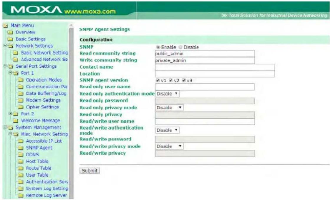
SNMP: To enable the SNMP Agent function, select the Enable option, and enter a community name (e.g., public).
Read community string (default=public_admin): This is a text password mechanism that is used to weakly authenticate queries to agents of managed network devices.
Write community string (default=private_admin): This is a text password mechanism that is used to weakly authenticate changes to agents of managed network devices.
Contact name: The optional SNMP contact information usually includes an emergency contact name and telephone or pager number.
Location: Use this optional field to specify the location string for SNMP agents such as the NPort 6000. This string is usually set to the street address where the NPort 6000 is physically located.
SNMP agent version: The NPort 6000 supports SNMP V1, V2, and V3.
Read-only and Read/ write access control
The following fields allow you to define user names, passwords, and authentication parameters for two levels of access: read-only and read/write. The name of the field will indicate which level of access it refers to. For example, Read-only authentication mode allows you to configure the authentication mode for read-only access, whereas Read/write authentication mode allows you to configure the authentication mode for read/write access. For each level of access, you may configure the following:
User name: Use this optional field to identify the user name for the specified level of access.
Authentication mode (default=Disable): Use this field to select MD5 or SHA as the method of password encryption for the specified level of access, or to disable authentication
Privacy mode (default=Disable): Use this field to enable to disable DES_CBC data encryption for the specified level of access.
Password: Use this field to set the password for the specified level of access.
Privacy: Use this field to define the encryption key for the specified level of access
DDNS
Please refer to Appendix C, Dynamic Domain Name Server, for information on setting up DDNS on your NPort 6000
Host Table
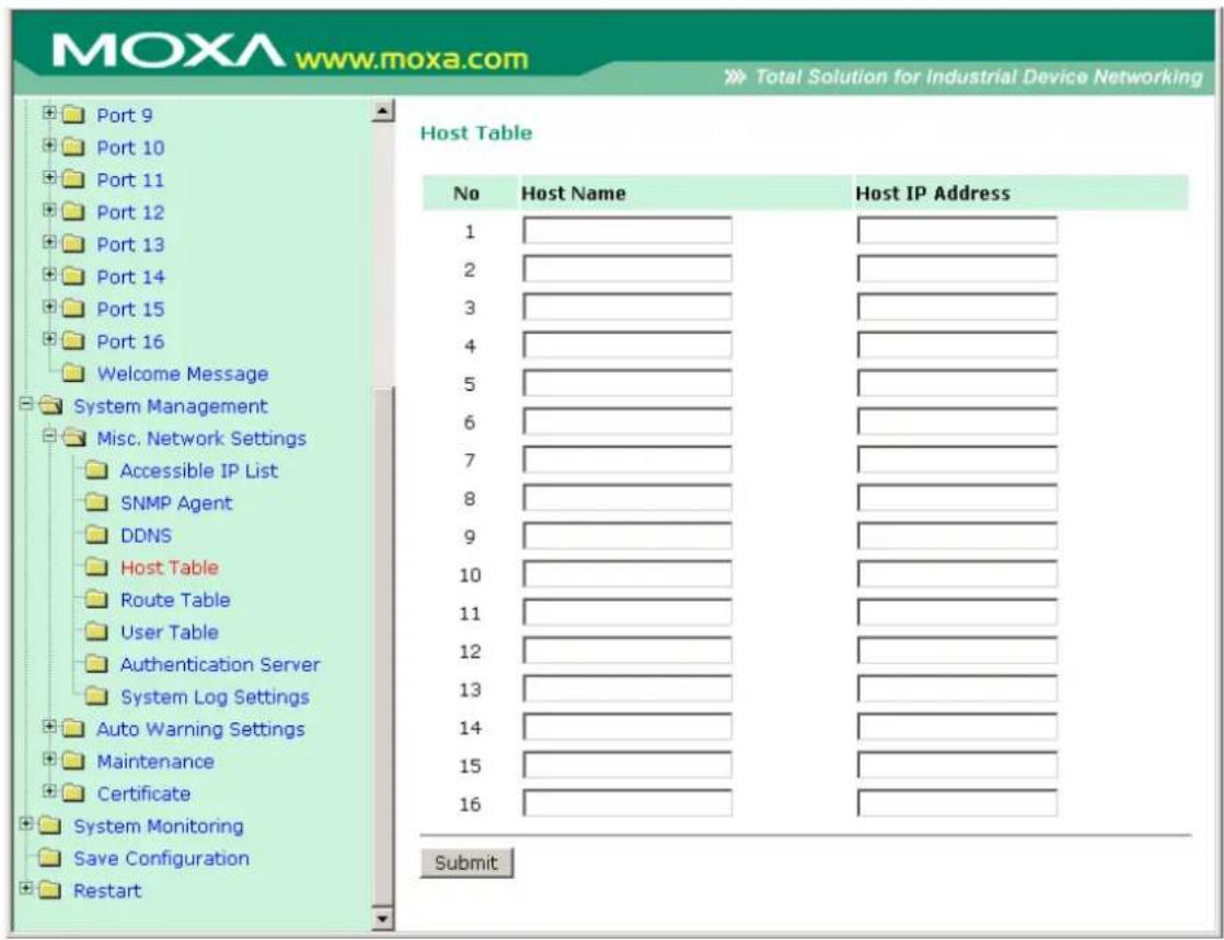
The Host Table may be used to simplify IP address entry on the NPort 6000 console by assigning a Host Name to a Host IP Address. When you assign a Host Name to a Host IP Address, you may then use the Host Name for some fields on the console rather than entering the IP address. Up to 16 entries can be stored on the Host Table.
User Table
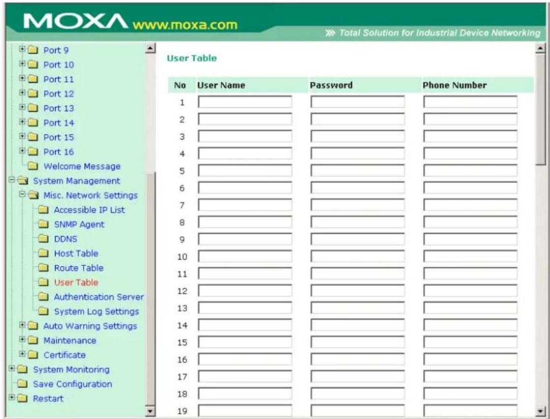
The NPort 6000 User Table may be used for to authenticate users for terminal or reverse terminal access and is useful if you do not have an external RADIUS server for authentication. The NPort 6000 User Table stores up to 64 entries, with fields for User Name, Password, and Phone Number.
Authentication Server
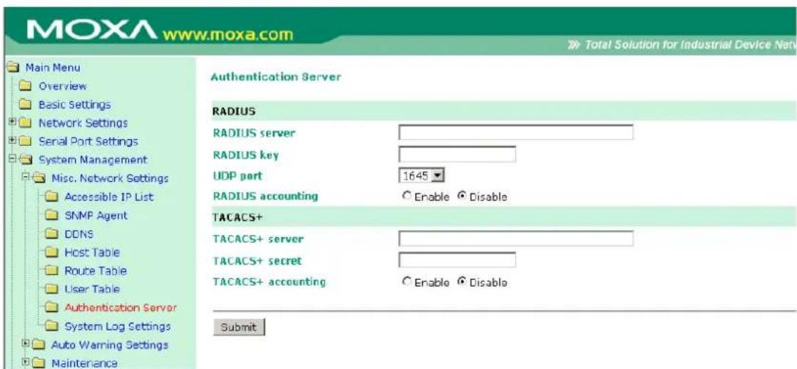
RADIUS server IP: If you are using a RADIUS server for user authentication, enter its IP address here.
RADIUS key: If you are using a RADIUS server for user authentication, enter its password here.
UDP port (default=1645): If you are using a RADIUS server, enter its UDP port assignment here.
RADIUS accounting: Use this field to enable or disable RADIUS accounting.
TACACS+ server: If you are using a TACACS+ server for user authentication, enter its IP address or domain name here.
TACACS+ secret: If you are using a TACACS+ server for user authentication, enter its password here.
TACACS+ accounting: Use this field to enable or disable TACACS+ accounting.
System Log Settings
System Log Settings
| Event Group | Local Log | Remote Log | Summary |
| System | System Cold Start, System Warm Start | ||
| Network | DHCP/BOOTP/PPPoE Get IP/Renew, NTP, Mail Fail, NTP Connect Fail, IP Conflict, Network Link Down | ||
| Config | Login Fail, IP Changed, Password Changed, Config Changed, Firmware Upgrade, SSL Certificate Import, Config Import, Config Export | ||
| OpMode | Connect, Disconnect, Authentication Fail, Restart |
Submit
System Log Settings allow the administrator to customize which network events are logged by the NPort 6000. Events are grouped into four categories, known as event groups, and the administrator selects which groups to log under Local Log. The actual system events that would be logged for each system group are listed under summary. For example, if System was enabled, then System Cold Start events and System Warm Start events would be logged.
| Local Log | Keep the log into the flash of NPort 6000 up to 512 items. |
| Remote Log Keep the log into | to the remote defined Log Server.You will need to assign a remote Log Server in the System Management / Misc.Network Settings / Remote Log Settings if remote log is checked. |
System
| System Cold Start NPort 60 | 00 cold start. |
| System Warm Start NPort 60 | 000 warm start. |
Network
| DHCP/BOOTP/PPPoE Get IP/Renew | IP of the NPort 6000 is refreshed. |
| NTP | Time synchronization successful. |
| NTP Connect Fail | The NPot 6000 failed to connect to the NTP Server. |
| Mail Fail | Failed to deliver the E-mail. |
| IP Conflict | There is an IP conflict on the local network. |
| Network Link Down LAN 1 Link is down. | |
Config
| Login Fail | |
| IP Changed | Static IP address was changed. |
| Password Changed | Administrator Password was changed. |
| Config Changed | The NPort 6000's configuration was changed. |
| Firmware Upgrade | Firmware was upgraded. |
| SSL Certificate Import | SSL Certificate was impoted. |
| Config Import | Config was impoted. |
| Config Export | Config was expoted. |
OpMode
| Connect Op Mode is in used | |
| Disconnect | Op Mode switched from in use to disconnect. |
| Authentication Fail | The Authentication failed in terminal; reverse terminal; or dial in/out operation modes |
| Restart Serial port was restarted. | |
Configure the Remote Log Server
Remote Log Server
Configuration
SYSLOG server
SYSLOG facility
SYSLOG severity
Submit
SYSLOG server
IP address or domain name of remote log server.
SYSLOG facility
Syslog Facility is one information field associated with a syslog message.
SYSLOG severity
Order of severity, listed from most severe to least severe.
| 0 | Emergency |
| 1 | Alert |
| 2 | Critical |
| 3 | Error |
| 4 | Warning |
| 5 | Notice |
| 6 | Informational |
| 7 | Debug |
Auto Warning Settings
Event Settings
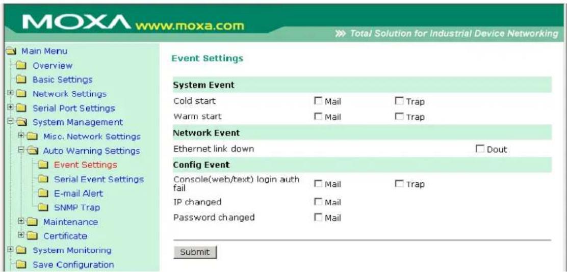
On the Event Settings page, you may configure how administrators are notified of certain system, network, and configuration events. Depending on the event, different options for automatic notification are available, as shown above. Mail refers to sending an e-mail to a specified address. Trap refers to sending an SNMP Trap.
Dout is only available on the NPort 6450 and 6650 and refers to changing the status of the relay output (the DOUT socket at the back of the NPort 6000) and of the alarm LED.
Cold start: This refers to starting the system from a power off state, or after upgrading your firmware
Warm start: This refers to restarting the NPort 6000 without turning the power off.
Network Event: These settings are only available on the NPort 6450 and 6650. Ethernet1 refers to the built-in Ethernet port, and Ethernet2 and Ethernet3 refer to Ethernet ports that are added through optional network modules. These settings configure the NPort to change the status of the relay output and alarm LED if the specified connection goes down.
Console(web/text) login auth fail: This field refers to a failed attempt to log in to a password-protected NPort 6000 console.
IP changed: With this option selected, the NPort 6000 will attempt to send an e-mail warning before it reboots after an IP address change. However, the NPort 6000 will reboot with the new IP address, regardless of whether or not the e-mail transmission is successful.
Password changed: With this option selected, the NPort 6000 will attempt to send an e-mail warning before it reboots with a new console password. If the NPort 6000 is unable to send an e-mail message to the mail server within 15 seconds, it will still reboot without sending the e-mail.
Serial Event Settings
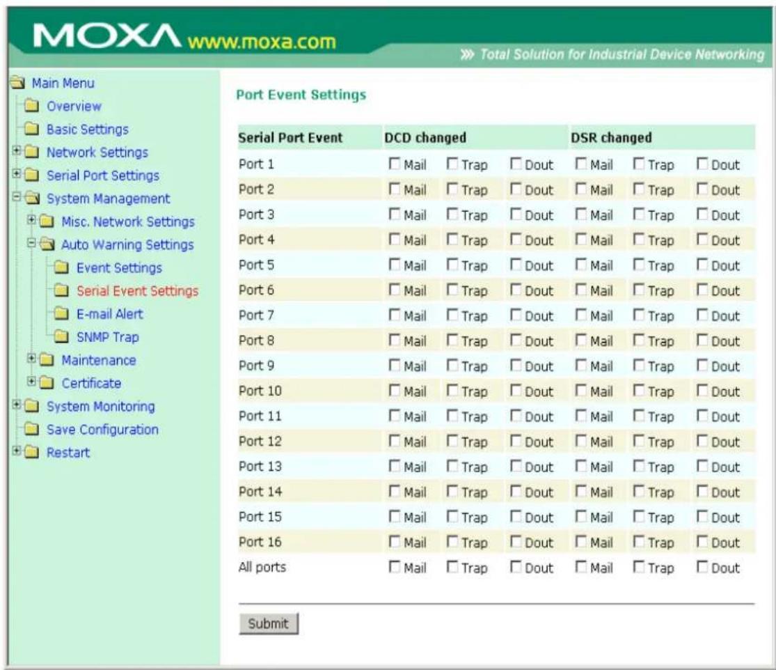
On the Serial Event Settings page, you may configure how administrators are notified of each serial port's DCD and DSR changes. Mail refers to sending an e-mail to a specified address. Trap refers to sending an SNMP Trap. Dout is only available on the NPort 6450 and 6650 and refers to changing the status of the relay output (the DOUT socket at the back of the NPort 6000) and of the alarm LED.
DCD changed
A change in the DCD (Data Carrier Detect) signal indicates that the modem connection status has changed. For example, if the DCD signal changes to low, it indicates that the connection line is down. When the DCD signal changes to low, the NPort 6000 will automatically send a warning to the administrator as configured on the Serial Event Settings page.
For the NPort 6450 and 6650, after the relay output status has been changed, administrators may reset its status by selecting Acknowledge Event from the NPort 6000 console, or by correcting the DCD signal. Please refer to the section on System Monitoring later in this chapter for more information.
DSR changed
A change in the DSR (Data Set Ready) signal indicates that the data communication equipment is powered off. For example, if the DSR signal changes to low, it indicates that the data communication equipment is powered down. When the DSR signal changes to low, the NPort 6000 will automatically send a warning to the administrator as configured on the Serial Event Settings page.
For the NPort 6450 and 6650, after the relay output status has been changed, administrators may reset its status by selecting Acknowledge Event from the NPort 6000 console, or by correcting the DSR signal. Please refer to the section on System Monitoring later in this chapter for more information.

ATTENTION
SNMP indicates a change in DCD or DSR signals but does not differentiate between the two. A change in either signal from “−” to “+” is indicated by “link up,” and a change in either signal from “+” to “−” is indicated by “link down.”
E-mail Alert
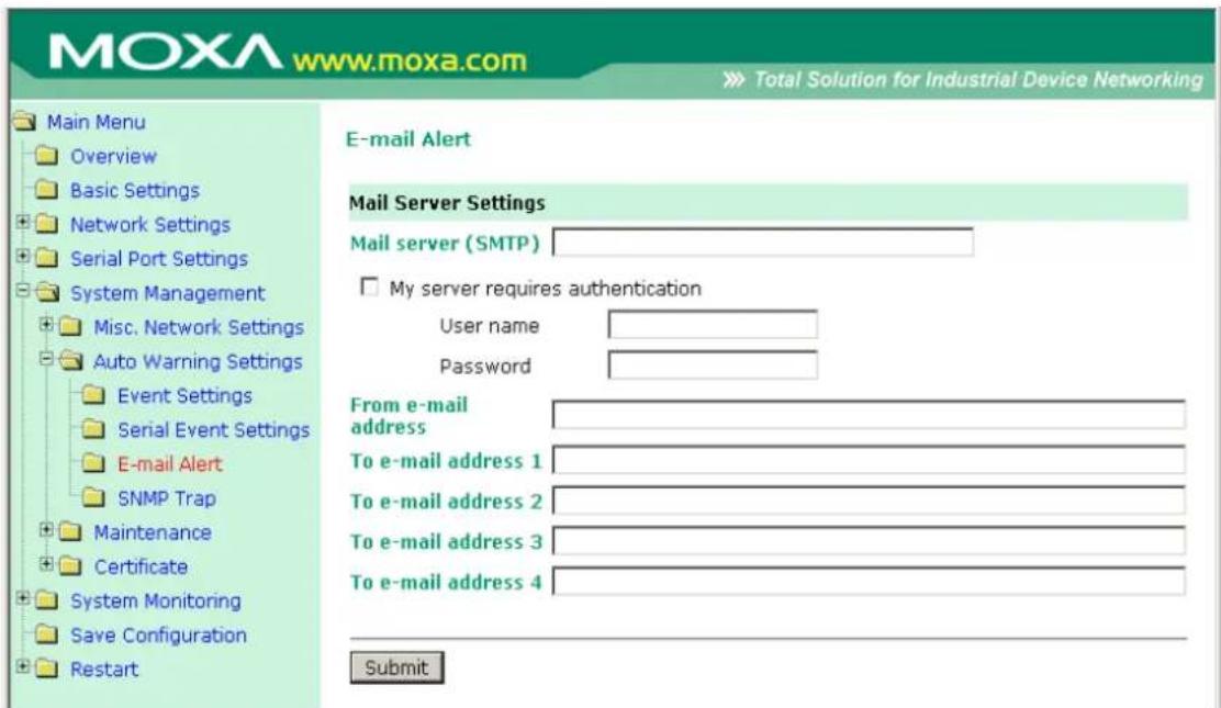
The E-mail Alert settings configure how e-mail warnings are sent for system and serial port events. You may configure up to 4 e-mail addresses to receive automatic warnings.

ATTENTION
Consult your Network Administrator or ISP for the proper mail server settings. The Auto warning function may not work properly if it is not configured correctly. The NPort 6000's SMTP AUTH supports LOGIN, PLAIN, and CRAM-MD5 (RFC 2554).
Mail server: This field is for your mail server's domain name or IP address.
User name: This field is for your mail server's user name, if required.
Password: This field is for your mail server's password, if required.
From e-mail address: This is the e-mail address from which automatic e-mail warnings will be sent.
To e-mail address 1 to 4: This is the e-mail address or addresses to which the automatic e-mail warnings will be sent.
SNMP Trap
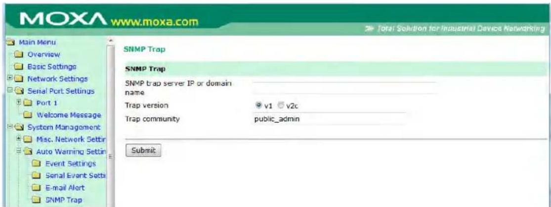
SNMP trap server IP: Use this field to indicate the IP address to use for receiving SNMP traps.
Trap version (default=v1): Use this field to select the SNMP trap version.
Trap community (default=public_admin): Use this field to designate the SNMP trap community.
Maintenance
Console Setting
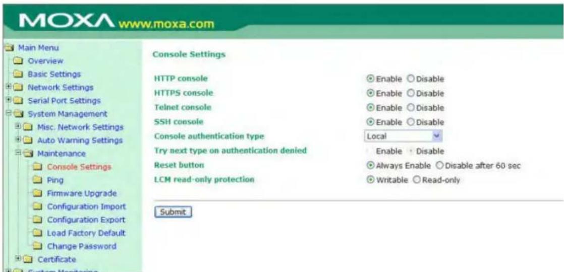
On this screen, access to different NPort 6000 configuration console options (HTTP, HTTPS, Telnet, SSH) can be enabled or disabled. The NPort 6000 front panel, known as the LCM (Liquid Crystal Module), may be configured for read-only or writeable access. In other words, you can use the front panel to check console settings only (read-only access) or to actually make changes to the settings (writeable access). Note that if the console is
password-protected and LCM is configured for writeable access, you will need to enter the password to submit any console setting changes. Please refer to Change Password later in this chapter for more information on passwords. Finally, you may also enable or disable the reset button.
Ping
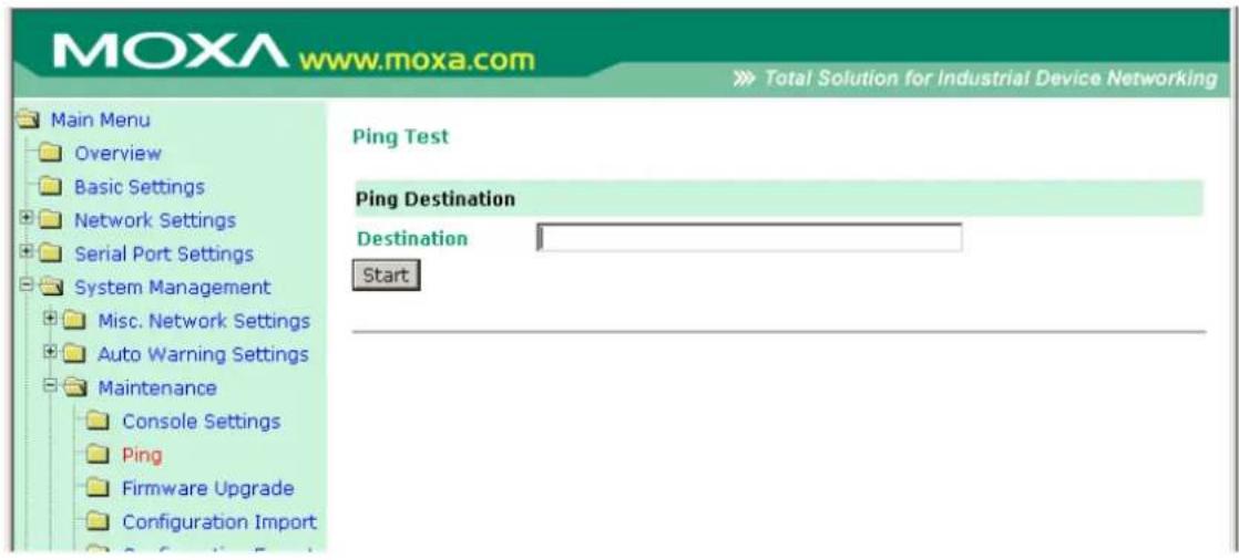
You can ping an IP address from the NPort 6000 web console in order to test the Ethernet connection. Enter the IP address or domain name in the Destination field to make sure that the connection is OK.
Firmware Upgrade
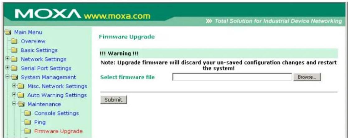
The NPort 6000's firmware can be upgraded though the web console, serial console, or through NPort Search Utility. If you have made any changes to your configuration, remember to save the configuration first before upgrading the firmware. Please refer to Save Configuration later in this chapter for more information. Any unsaved changes will be discarded when the firmware is upgraded. To upgrade the firmware, simply enter the file name and click Submit. The latest firmware can be downloaded at www.moxa.com.
Configuration Import/ Export
The NPort 6000 can share or back up its configuration by exporting all settings to a file, which can then be imported into another NPort 6000.
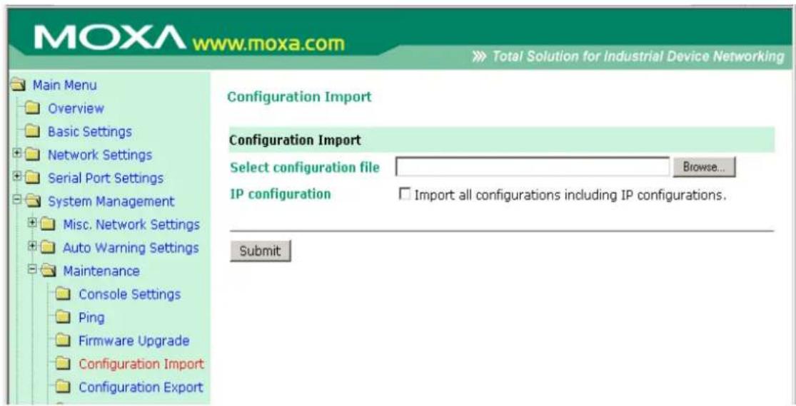
To import a configuration, go to System Management → Maintenance → Configuration Import. Enter the configuration file path/name and click Submit. The NPort 6000's configuration settings will be updated according to the configuration file. If you also wish to import the IP configuration (i.e., the NPort 6000's IP address, netmask, gateway, etc.), make sure that I import all configurations including IP configurations is checked off.
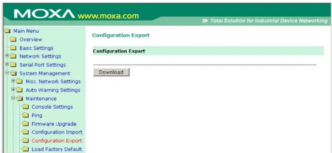
To export a configuration, go to System Management, Maintenance, Configuration Export and click Download. A standard download window will appear, and you will be able to download the configuration into a file name and location of your choice.
Load Factory Defaults
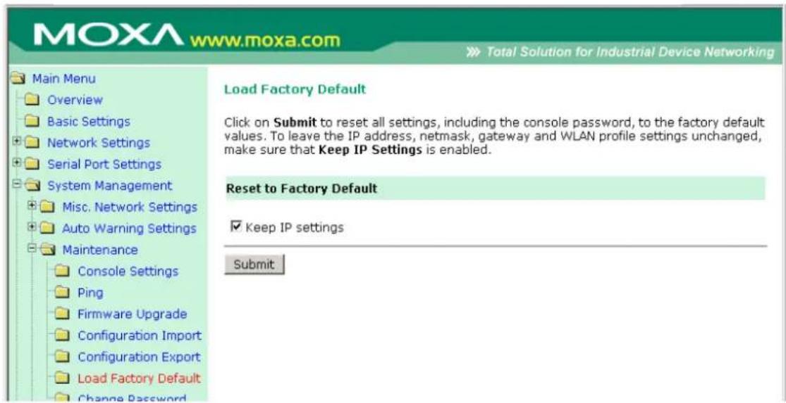
This function will reset all of NPort 6000's settings to the factory default values. All previous settings including the console password will be lost. If you wish to keep the NPort 6000 IP address, netmask, and other IP settings, make sure Keep IP settings is checked off before loading the factory defaults.
Change Password
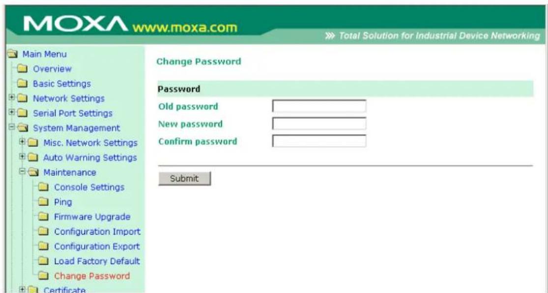
For all changes to the NPort 6000's password protection settings, you will first need to enter the old password. Leave this blank if you are setting up password protection for the first time. To set up a new password or change the existing password, enter your desired password under both New password and Confirm password. To remove password protection, leave the New password and Confirm password boxes blank.

ATTENTION
If you forget the password, the ONLY way to configure the NPort 6000 is by using the reset button on the NPort 6000's casing to load the factory defaults.
Before you set a password for the first time, it is a good idea to export the configuration to a file when you have finished setting up your NPort 6000. Your configuration can then be easily imported back into the NPort 6000 if you need to reset the NPort 6000 due to a forgotten password or for other reasons. Please refer to the section on Configuration Import/Export earlier in this chapter for more details.
Certificate
Ethernet SSL Certificate Import
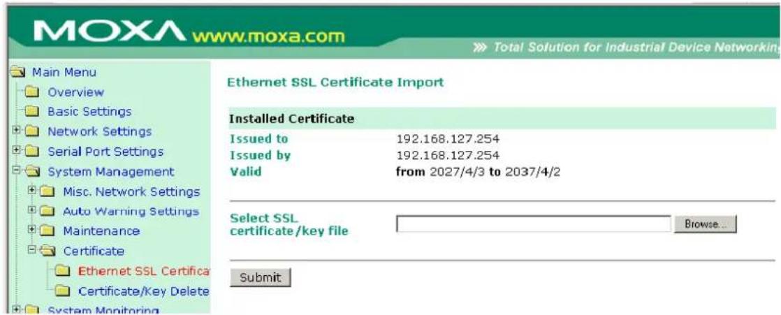
The certificate/key imported here will be used for HTTPS/SSH/Secure OP modes and will only accept PEM format
Certificate/ Key Delete
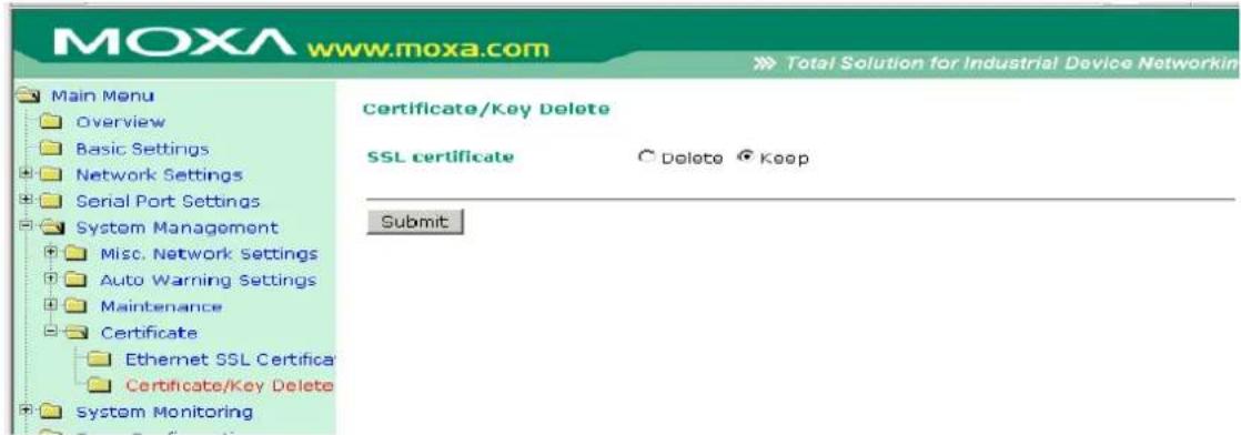
System Monitoring
Serial to Network Connections
Go to Serial to Network Connections under Serial Status to view the operation mode and status of each connection for each serial port. All monitor functions will refresh automatically every 5 seconds.
![MOXA www.moxa.com Main Menu Overview Basic Settings Network Settings Serial Port Settings System Management Misc. Network Settings Auto Warning Settings Maintenance Certificate System Monitoring Serial Status Serial to Network Con Serial Port Status Serial Port Error Coun Serial Port Settings Cipher Usage Status System Status Save Configuration Restart Serial to Network Connections Port OP Mode Connections 1 Device Control/RealCOM[ ][ ][ ][ ] 2 Device Control/RealCOM[ ][ ][ ][ ] 3 Device Control/RealCOM[ ][ ][ ][ ] 4 Device Control/RealCOM[ ][ ][ ][ ] 5 Device Control/RealCOM[ ][ ][ ][ ] 6 Device Control/RealCOM[ ][ ][ ][ ] 7 Device Control/RealCOM[ ][ ][ ][ ] 8 Device Control/RealCOM[ ][ ][ ][ ] 9 Device Control/RealCOM[ ][ ][ ][ ] 10 Device Control/RealCOM[ ][ ][ ][ ] 11 Device Control/RealCOM[ ][ ][ ][ ] 12 Device Control/RealCOM[ ][ ][ ][ ] 13 Device Control/RealCOM[ ][ ][ ][ ] [ ] [ ] [ ] [ ] [ ] [ ] [ ] [ ] [ ] [ ] [ ] [ ] [ ] [ ] [ ] [ ] [ ] [ ] [ ] [ ] [ ] [ ] [ ] [ ] [ ] [ ] [ ] [ ] [ ] [ ] [ ] [ ] [ ] [ ] [ ] [ ] [ ] [ ] [ ] [ ] [ ] [ ] [ ] [ ] [ ] [ ] [ ] [ ] [ ] [ ] ( )](/content/2026/06/1269850/images/f2996519f30c43cb7b9b08a53b3f11aed80a0153353ba1f04e9b2337a4b4fec7.jpg)
Serial Port Status
Go to Serial Port Status under Serial Status to view the current status of each serial port.
Serial Port Status → Buffering.

Monitor port-buffering usage (bytes) of each serial port.
Serial Port Error Count
Go to Serial Port Error Count under Serial Status to view the error count for each serial port.
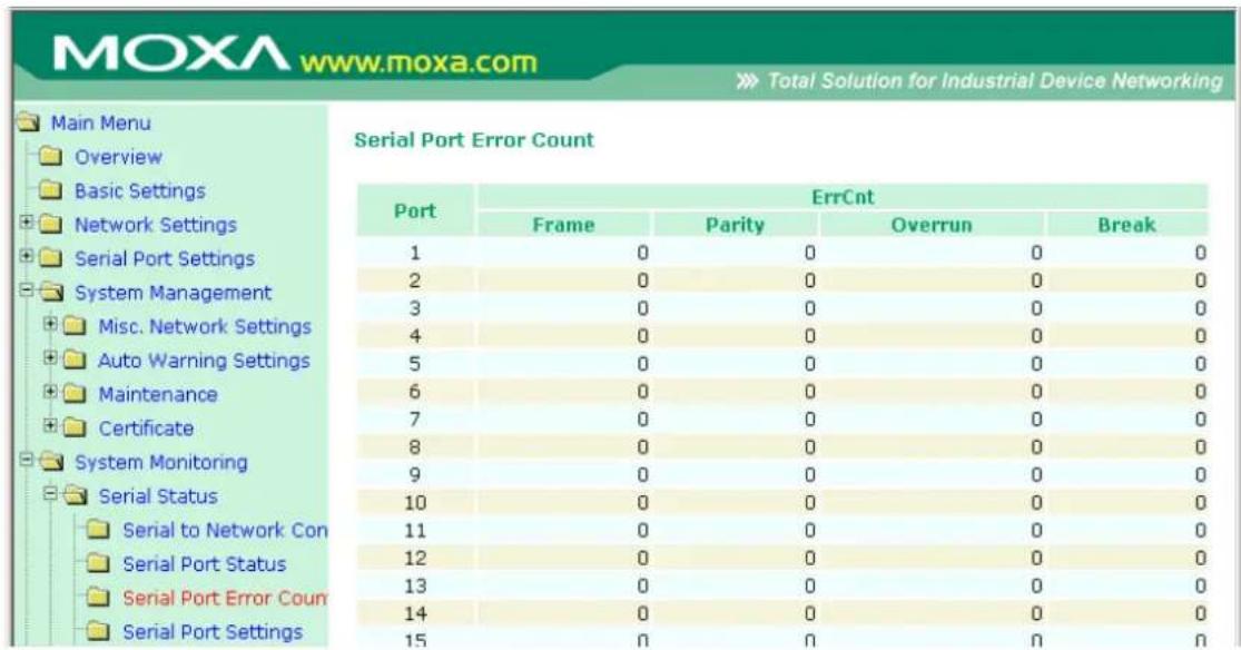
Frame: Framing error indicates that the received character did not have a valid stop bit.
Parity: Parity error indicates that the received data character does not match the parity selected.
Overrun: The NPort is unable to hand-receive data to a hardware buffer because the input rate exceeds the NPort's ability to handle the data.
Break: Break interrupt indicates that the received data input was held low for longer than a full-word transmission time. A full-word transmission time is defined as the total time to transmit the start, data, parity, and stop bits.
Serial Port Settings
Go to Serial Port Settings under Serial Status to view a summary of the settings for each serial port.
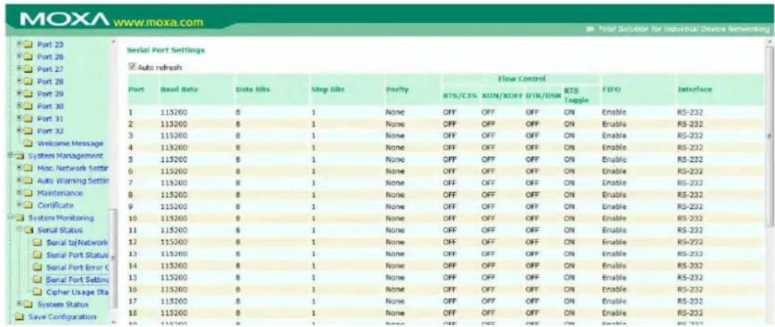
Serial Cipher Usage Status
Serial Status → Cipher Usage Status
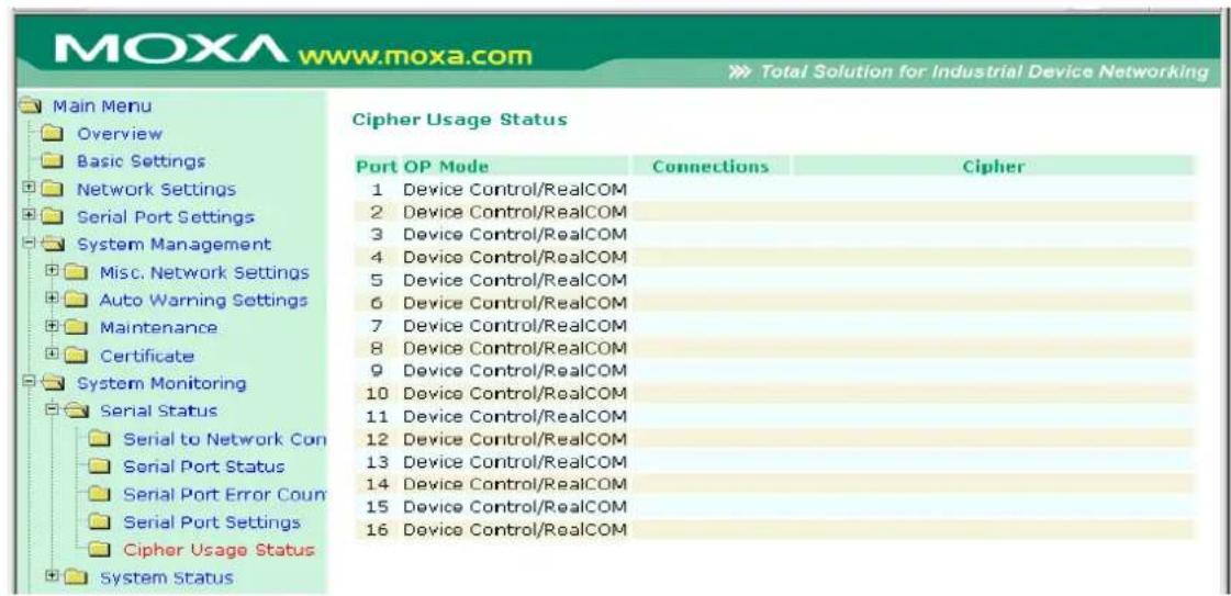
Monitor cipher usage and connection status of each serial port. It depends on Cipher Settings.
Network Connections
Go to Network Connections under System Status to view network connection information.
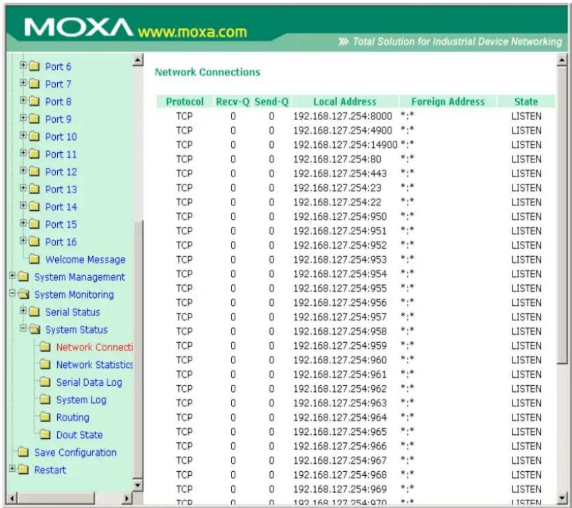
Network Statistics
Go to Network Statistics under System Status to view network statistics.
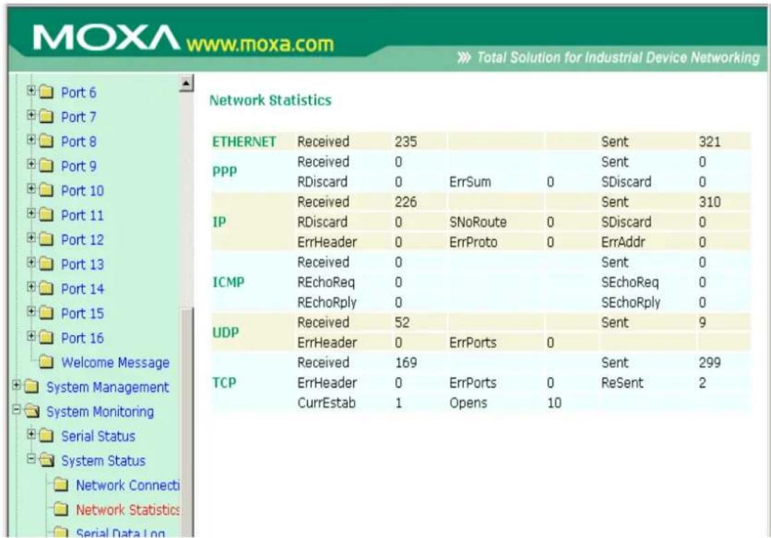
Ethernet statistics
Sent: Total number of output datagram packets delivered to the Ethernet.
Received: Total number of input datagram packets received from the Ethernet.
Sent: Total number of output datagram packets delivered to the Ethernet.
PPP statistics
Received: Received IP datagram packets.
RDiscard: Received but discarded IP datagram packets.
ErrSum: Checksum error packets.
Sent: Sent IP datagram packets.
SDiscard: Sent but discarded IP datagram packets.
IP statistics
Received: Received IP datagram packets.
RDiscard: Received but discarded PPP datagram packets.
ErrHeader: Received but discarded IP datagram packets due to errors in IP headers.
SNoRoute: Received IP datagram packets for wrong route.
ErrProto: Locally addressed IP datagram packet received successfully but discarded for not matching one of TCP, UDP, ICMP protocols offered by CN2500.
Sent: Sent IP datagram packets.
SDiscard: Sent but discarded IP datagram packets.
ErrAddr: Sent datagram packet discarded for invalid destination IP address.
ICMP statistics
Received: Received packets of ICMP messages.
Sent: Sent packets of ICMP messages.
REchoReq: Received packets from remote Ping request.
REchoRply: Responding packets to remote Ping request.
SEchoReq: Received packets from local ping request.
SEchoRply: Responding packets to local ping request.
UDP statistics
Received: Received UDP datagram packets.
ErrPorts: Received UDP datagram packets with invalid destination port.
ErrHeader: Received UDP datagram packet with incorrect header.
Sent: Sent UDP datagram packets.
TCP statistics
Received: Total received packets of segments, including error packets.
ErrHeader: Error packets (e.g., bad TCP checksums).
CurrEstab: The counter of TCP connections for which the current state is either ESTABLISHED or CLOSE-WAIT.
ErrPorts: Received TCP datagram packets with invalid destination port.
Opens: TCP connections.
Sent: Total sent packets, including those on current connections.
ReSent: Retransmitted packets.
Network Module
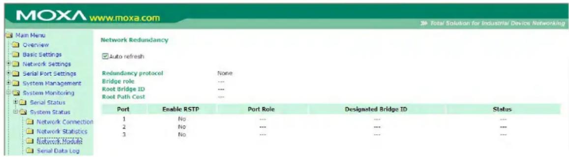
Check the information and status of the Network Module inserted in the NPort 6000.
Auto Refresh:
Default (Enable): Auto refresh the status every 5 seconds.
Redundancy Protocol:
Shows which communication protocol is in use: Turbo Ring, Turbo Ring V2, RSTP, or none.
Status:
Shows Healthy if the ring is operating normally, and shows Break if the ring's backup link is active.
Master Slave:
Indicates whether or not this NPort 6000 is the master of the Turbo Ring. (This field appears only when Turbo Ring or Turbo Ring V2 modes are active.)

ATTENTION
The user does not need to set the master to use Turbo Ring. If no master is set, the Turbo Ring protocol will assign master status to one of the EDS units in the ring. The master is only used to determine which segment serves as the backup path.
1st Redundant Port Status (Port 1)
2nd Redundant Port Status (Port 2)
The "Ports Status" indicators show Forwarding for normal transmission, Blocking if this port is connected to a backup path and the path is blocked, and Link down if there is no connection.
Serial Data Log
Data logs for each serial port can be viewed in ASCII or HEX format. After selecting the serial port and format, you may click Select all to select the entire log if you wish to copy and paste the contents into a text file.
![MOXA www.moxa.com Total Solution for Industrial Device Networking Port 6 Port 7 Port 8 Port 9 Port 10 Port 11 Port 12 Port 13 Port 14 Port 15 Port 16 Welcome Messag System Managerer System Monitoring Serial Status System Status Network Conne Network Statis Serial Data Log System Log Routing Dout State Save Configuration Restart Serial Data Log Data Log - ASCII Select port Port1 [ASCII][HEX] Select all Clear log Refresh](/content/2026/06/1269850/images/df716031e4360aded068a9c79461fe9467a1cd03b6ca7aca3a5b0710a0cdfc14.jpg)
System Log
This option displays the system log. You may click Select all to select the entire log if you wish to copy and paste the contents into a text file.
System Log
System Log
![2008/03/26 07:00:21 [System ] System Cold Start 2008/03/26 07:00:47 [Network] Ethernet1 Link Down 2008/03/26 07:01:20 [Config ] Config Changed 2008/03/26 07:01:28 [System ] System Warm Start 2008/03/26 07:02:08 [Config ] Config Changed 2008/03/26 07:02:17 [System ] System Warm Start 2008/03/26 07:02:33 [Network] Get IP Fail (IPv6)](/content/2026/06/1269850/images/771fb23017e04d0b24b0c9b81cab1cd74023ce0886adec3e2844592140af42bd.jpg)
Select all Clear log Refresh
Routing
Go to Routing under System Status to display the routing information.
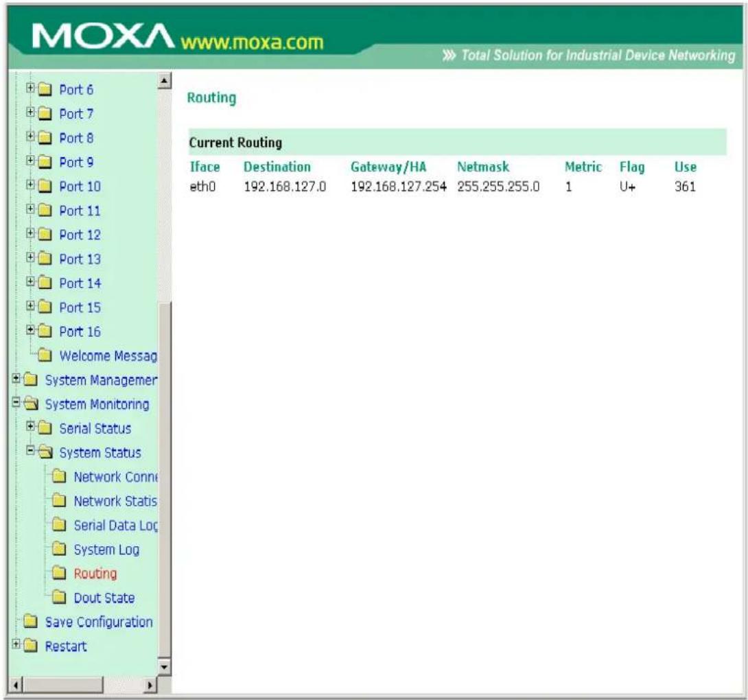
Iface: Name of the physical network interface.
Destination: Network or host that the router allows you to connect to.
Gateway: IP Address of the gateway you configured for this route. If you are directly connected, this is a local address. Otherwise, it is the address of the machine through which packets must be routed.
Netmask: Network pattern of the gateway.
Metric: Number of hops to the destination.
Flags: State of the route. Valid states are:
U up
D down
G route to a gateway
H route to a host
T setting in route table
R dynamic by RIP
Use: Correct number of packets being sent in this route.
PPP-Trace
Go to PPP-Trace under System Status to display the PPP-Trace information.
PPP states for the selected ports are shown. LCP (Link Control Protocol), which is an essential part of the PPP link, is used for establishing, configuring, and testing the data link connection.
Dout State (for 6450/6600)
Dout State refers to the relay output status, which can be configured to change upon the occurrence of certain system events through Auto Warning Settings under System Management. You may click Dout State under System Status to display a list of events that may cause a change to the Dout state. If a configured alarm event occurs, the alarm LED lights up and the Dout state changes, and you may come to this screen to determine the specific cause for the alarm. To reset the Dout state, click on Acknowledge Event. Note that the alarm LED will remain unchanged until the actual event has been resolved.
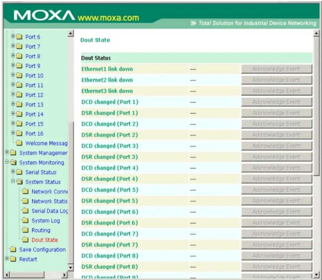
Save Configuration
Go to Save Configuration and then click Save to save the your submitted configuration changes to the NPort 6000's flash memory. The configuration changes will then be effective when the NPort 6000 is restarted. If you do not save your changes before restarting, they will be discarded.
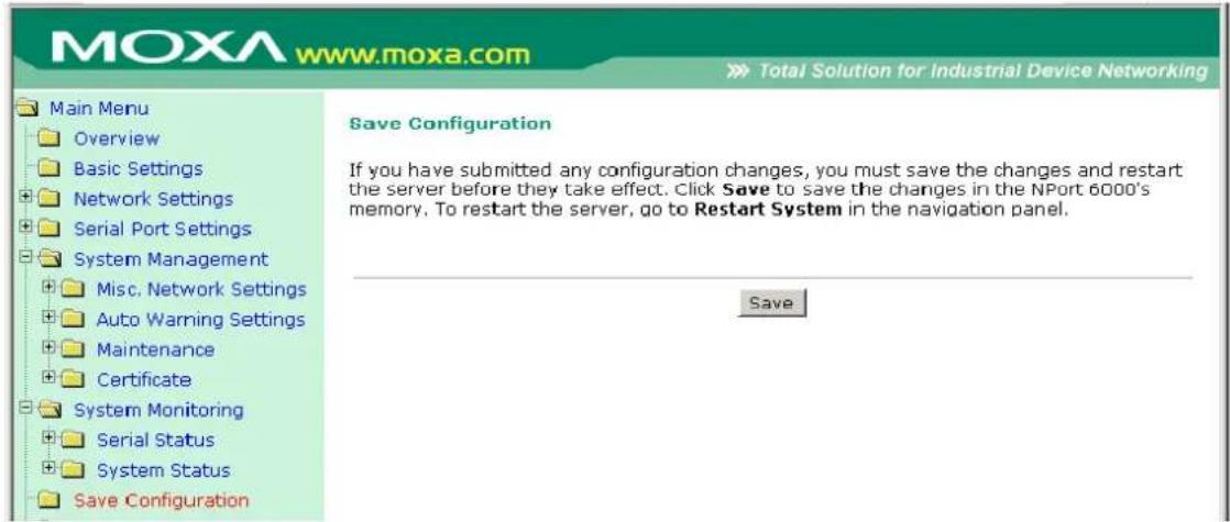
Restart
Restart System
Go to Restart System under Restart and then click Restart to restart the NPort 6000. Ensure that you save all your configuration changes before you restart the system or else these changes will be lost.
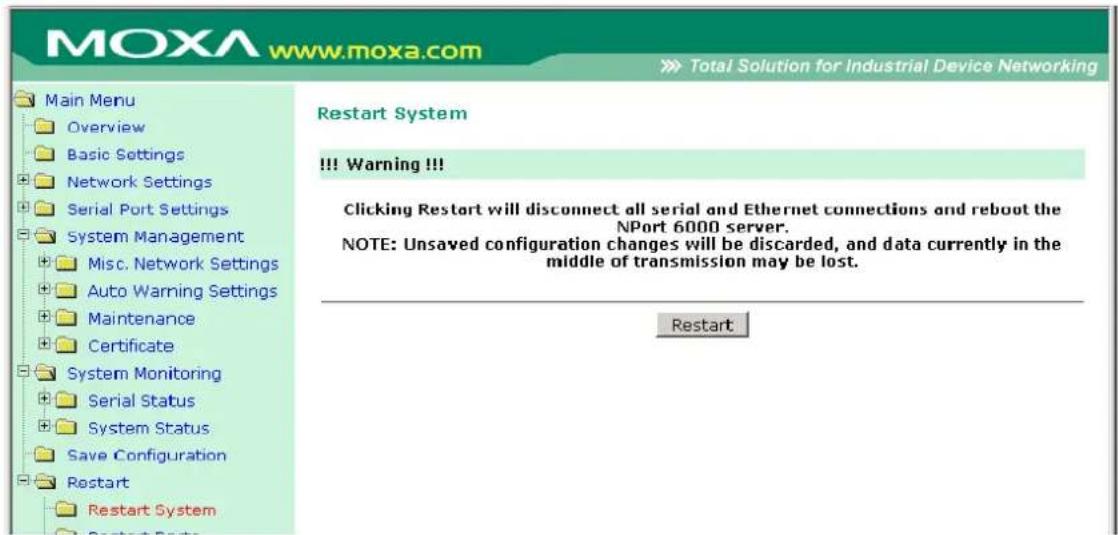
Restart Ports
Go to Restart Ports under Restart and then select the ports to be restarted. Click Select All to select all the ports. Click Submit to restart the selected ports.
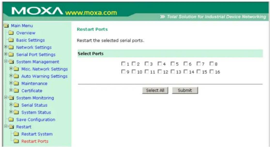
The following topics are covered in this chapter:
Overview
□ NPort Windows Driver Manager
- Installing NPort Windows Driver Manager
Using NPort Windows Driver Manager
□ NPort Search Utility
➢ Installing NPort Search Utility
- Configuring NPort Search Utility
☐ Linux Real TTY Drivers
Basic Procedures
Hardware Setup
➢ Installing Linux Real TTY Driver Files
Mapping TTY Ports
➢ Removing Mapped TTY Ports
➢ Removing Linux Driver Files
☐ The UNIX Fixed TTY Driver
Installing the UNIX Driver
➢ Configuring the UNIX Driver
Overview
The Documentation & Software CD included with your NPort 6000 is designed to make the installation and configuration procedure easy and straightforward. This auto-run CD includes NPort Windows Driver Manager (for COM mapping), NPort Search Utility (to broadcast search for all NPort 6000's accessible over the network), the NPort 6000 User's Manual, and the NPort firmware upgrade utility.
NPort Windows Driver Manager
Installing NPort Windows Driver Manager
NPort Windows Driver Manager is intended for use with NPort 6000 serial ports that are set to Real COM mode. The software manages the installation of drivers that allow you to map unused COM ports on your PC to serial ports on the NPort 6000. These drivers are designed for use with Windows 98/ME/2000/XP/2003. When the drivers are installed and configured, devices that are attached to serial ports on the NPort 6000 will be treated as if they were attached to your PC's own COM ports.
- Click the INSTALL COM Driver button in the NPort Installation CD auto-run window to install the NPort Windows Driver. Once the installation program starts running, click Yes to proceed.
- Click Next when the Welcome screen opens to proceed with the installation.
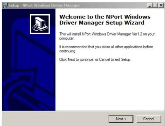
Click Next to install program files to the default directory, or click Browse to select an alternate location.
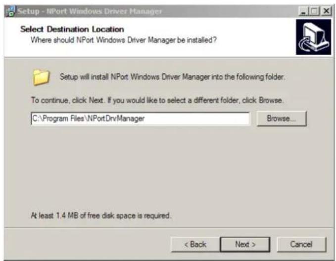
- Click Next to install the program's shortcuts in the appropriate Start Menu folder.
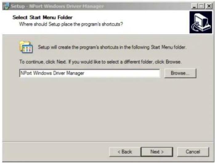
- Click Next to proceed with the installation. The installer then displays a summary of the installation options.
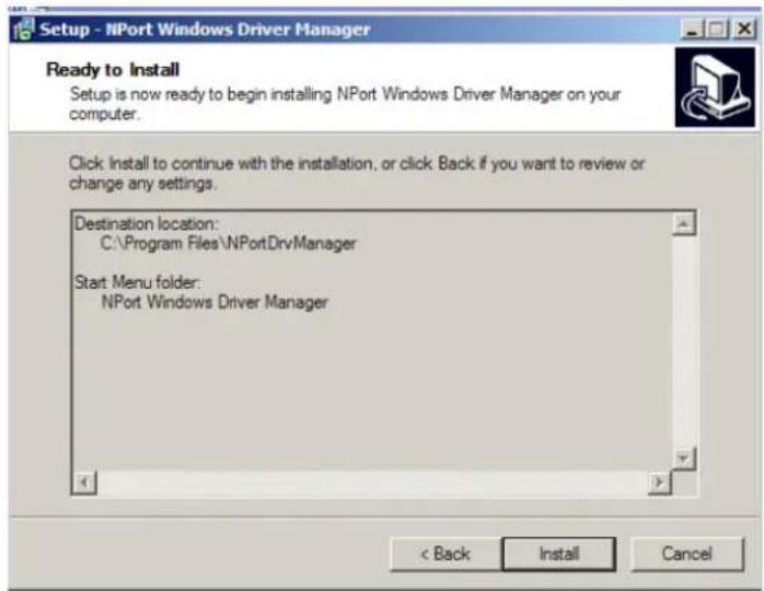
- Click Install to begin the installation. The setup window will report the progress of the installation. To change the installation settings, click Back and navigate to the previous screen. On Windows XP, the installer will display a message that the software has not passed Windows Logo testing. This is shown as follows:
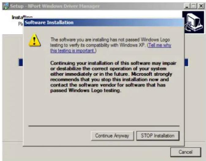
Click Continue Anyway to finish the installation.
- Click Finish to complete the installation of the NPort Windows Driver Manager.
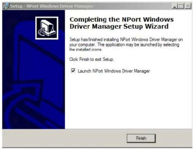
Using NPort Windows Driver Manager
Real COM Mode
After you install NPort Windows Driver Manager, you can set up the NPort 6000's serial ports as remote COM ports for your PC host. Make sure that the serial port(s) on your NPort 6000 are set to Real COM mode when mapping COM ports with the NPort Windows Driver Manager.
- Go to Start → NPort Windows Driver Manager → NPort Windows Driver Manager to start the COM mapping utility.
- Click the Add icon.
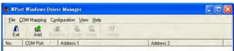
- Click Rescan to search for NPort device servers. From the list that is generated, select the server to which you will map COM ports, and then click OK. The default IPv4 address will be changed to IPv6 address when "Mapping IPv6 COM Port" is checked.
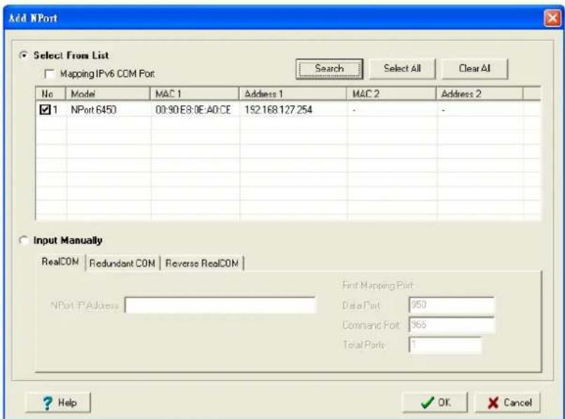
- Alternatively, you can select Input Manually and then manually enter the NPort IP Address, 1st Data Port, 1st Command Port, and Total Ports to which COM ports will be mapped. Click OK to proceed to the next step. Note that the Add NPort page supports FQDN (Fully Qualified Domain Name), in which case the IP address will be filled in automatically.
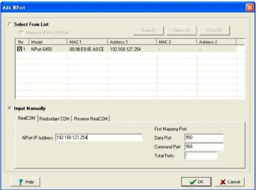
- COM ports and their mappings will appear in blue until they are activated. Activating the COM ports saves the information in the host system registry and makes the COM port available for use. The host computer will not have the ability to use the COM port until the COM ports are activated. Click Yes to activate the COM ports at this time, or click No to activate the COM ports later.
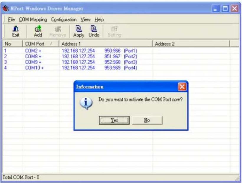
- In Windows XP, a message is displayed during activation of each port, indicating that the software has not passed Windows Logo certification. Click Continue Anyway to proceed.
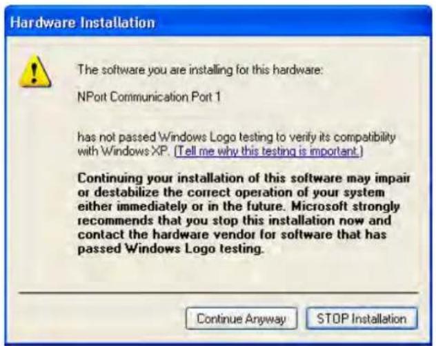
- Ports that have been activated will appear in black.
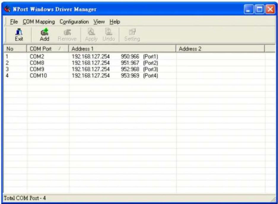
Reverse Real COM Mode
After you install NPort Windows Driver Manager, you can set up the NPort 6000's serial ports as remote COM ports for your PC host. Make sure that the serial port(s) on your NPort 6000 are set to Reverse Real COM mode when mapping COM ports with the NPort Windows Driver Manager.
- Go to Start → NPort Windows Driver Manager → NPort Windows Driver Manager to start the COM mapping utility.
- Click the Add icon.
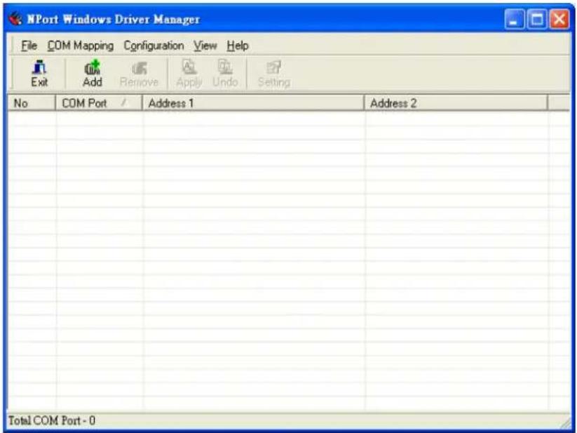
- Select Input Manually and click Reverse Real COM tab; then, manually enter the NPort MAC Address, 1st Mapping Port Index, and Total Ports. Click OK to proceed to the next step.
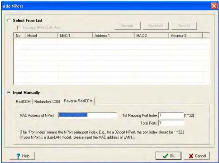
Depending on your application, it could be that only some ports will be set up for Reverse Real COM mode. The user should assign which ports of which NPorts will be mapped in Reverse RealCOM mode.
Example: If you want to map port 15 only for NPort 6000 (A), the configuration will be as follows:
| MAC Address of NPort | The MAC address of NPort (A) for identification | 00:90:18:18:f1:36 |
| 1st Mapping Port Index | Index or port 15 | 15 |
| Total Number of Ports | Only port 15 will be mapped, and the total number of ports should be 1 | 1 |
Example: If you want to map ports 3 to 15 for NPort 6000 (A), the configuration will be as follows:
| MAC Address of NPort | The MAC address of NPort (A) for identification | 00:90:18:18:f1:36 |
| 1st Mapping Port Index | Index the port 3 | 3 |
| Total Number of Ports | From port 3 to port 15 will be mapped, and the total number of ports should be 13 | 13 |
- Ports that have been activated will appear in black.
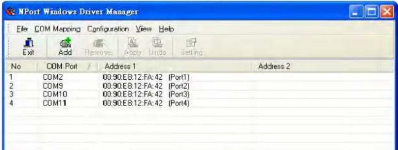
- For Reverse Real COM mode, users should assign the TCP port number for the Remote Host/Server. Click the Configuration tab to modify the port number.
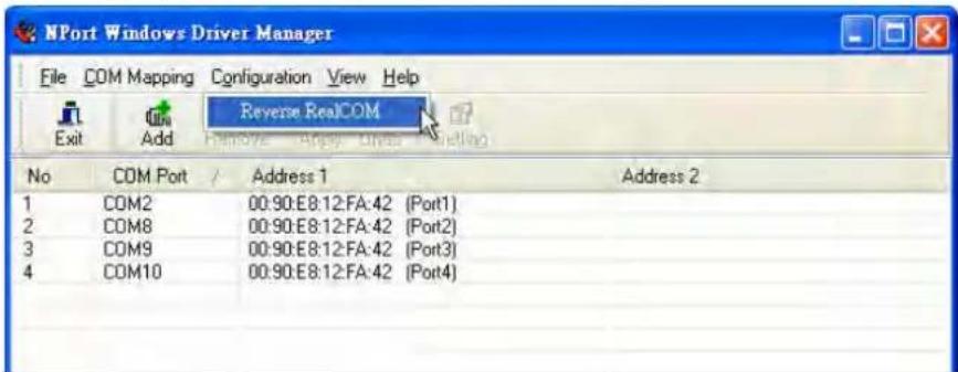
This is the TCP port number assignment for the remote host/server. It is the port number that the serial port of the NPort 6000 uses to establish the connections with Remote Host/Server. To avoid conflicts with well-known TCP ports, the default is set to 60950.
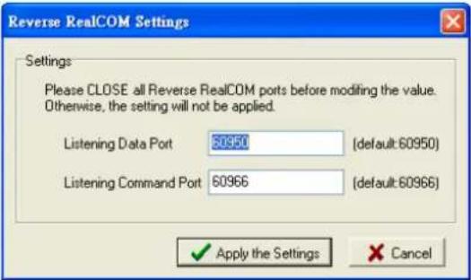
Configure the mapped COM ports
For Real COM Mode/Reverse Real COM Mode, to re-configure the settings for a particular serial port on the NPort 6000, select the row corresponding to the desired port and then click the Setting icon.
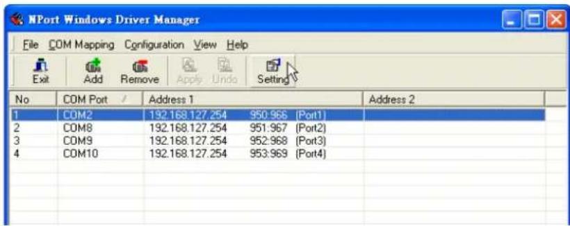
- On the Basic Setting window, use the COM Number drop-down list to select a COM number to be assigned to the NPort 6000's serial port that is being configured. Select the Auto Enumerating COM Number for Selected Ports option to automatically assign available COM numbers in sequence to selected serial ports. Note that ports that are "in use" will be labeled accordingly.
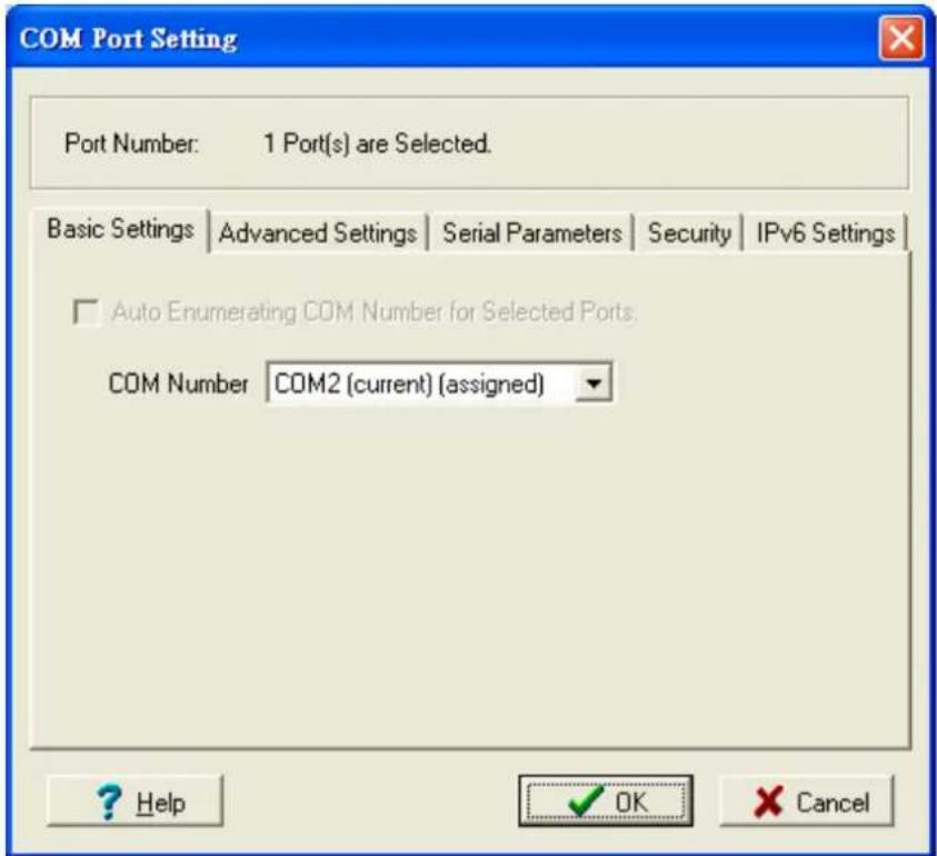
- Click the Advanced Setting tab to modify Tx Mode, FIFO, and Flash Flush.
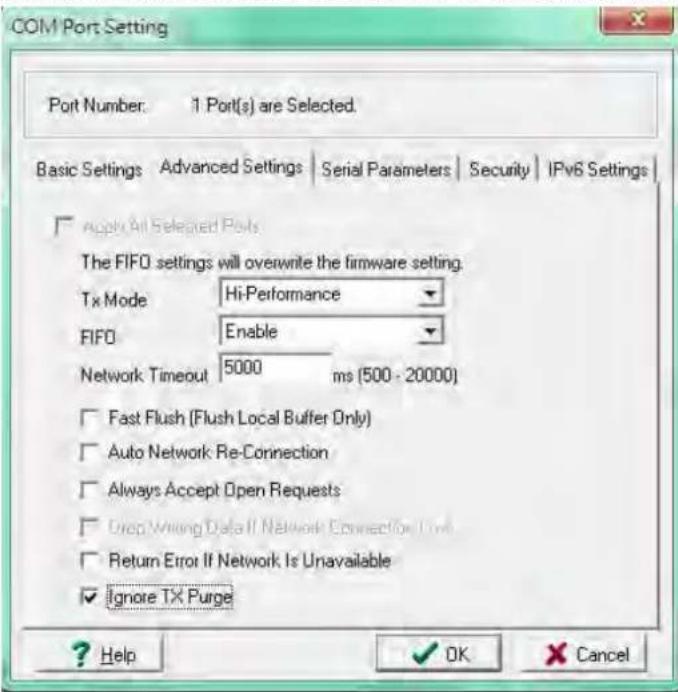
Tx Mode
Hi-Performance is the default for Tx mode. After the driver sends data to the NPort 6000, the driver immediately issues a "Tx Empty" response to the program. Under Classical mode, the driver will not send the "Tx Empty" response until after confirmation is received from the NPort 6000's serial port. This causes lower throughput. Classical mode is recommended if you want to ensure that all data is sent out before further processing.
FI FO
If FIFO is Disabled, the NPort 6000 will transmit one byte each time the Tx FIFO becomes empty, and an Rx interrupt will be generated for each incoming byte. This will result in a faster response and lower throughput.
Network Timeout
You can use this option to prevent blocking if the target NPort is unavailable.
Auto Network Re-Connection
With this option enabled, the driver will repeatedly attempt to re-establish the TCP connection if the NPort 6000 does not respond to background "check alive" packets.
Always Accept Open Requests
When the driver cannot establish a connection with the NPort, the user's software can still open the mapped COM port, just like an onboard COM port.
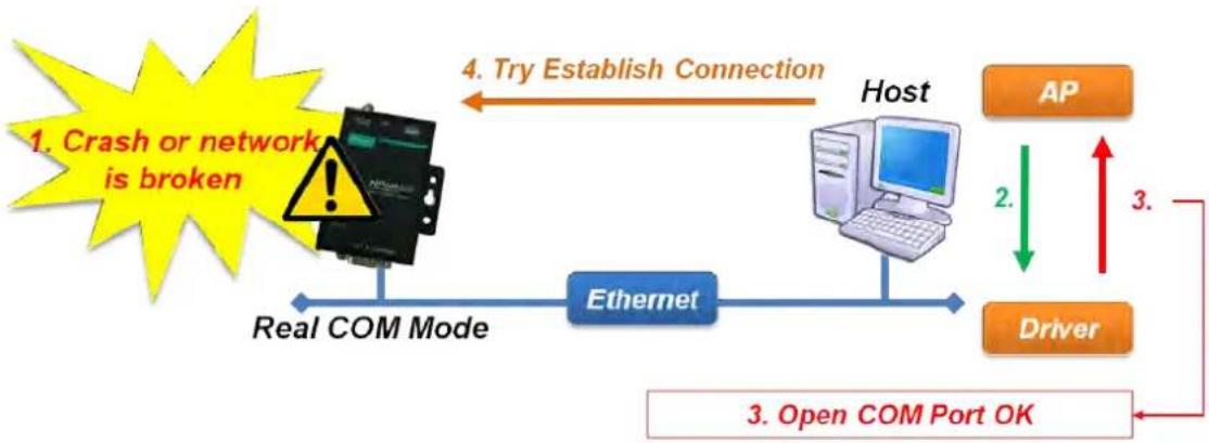
flowchart
graph TD
    A["1. Crash or network is broken"] --> B["Host"]
    B --> C["AP"]
    C --> D["Driver"]
    D --> E["Open COM Port OK"]
    E --> F["3. Open COM Port OK"]
    F --> G["Real COM Mode"]
    G --> H["Ethernet"]
    H --> I["4. Try Establish Connection"]
    I --> J["2."]
    J --> C
    style A fill:#FFD700,stroke:#333
    style B fill:#E6F5FF,stroke:#333
    style C fill:#FFA500,stroke:#333
    style D fill:#FFA500,stroke:#333
    style E fill:#FFA500,stroke:#333
    style F fill:#FFA500,stroke:#333
    style G fill:#FFA500,stroke:#333
    style H fill:#FFA500,stroke:#333
    style I fill:#FFA500,stroke:#333
Return error if network is unavailable
If this option is disabled, the driver will not return any errors even when a connection cannot be established to the NPort 6000. With this option enabled, calling the Win32 Comm function will result in the error return code "STATUS_NETWORK_UNREACHABLE" when a connection cannot be established to the NPort 6000. This usually means that your host's network connection is down, perhaps due to a cable being disconnected. However, if you can reach other network devices, it may be that the NPort 6000 is not powered on or is disconnected. Note that Auto Network Re-Connection must be enabled in order to use this function.
Fast Flush (only flushes the local buffer)
For some applications, the user's program will use the Win32 "PurgeComm()" function before it reads or writes data. After a program uses this PurgeComm() function, the NPort driver continues to query the NPort's firmware several times to make sure no data is queued in the NPort's firmware buffer, rather than just flushing the local buffer. This design is used to satisfy some special considerations. However, it may take more time (about several hundred milliseconds) than a native COM1 due to the additional time spent communicating across the Ethernet. This is why PurgeComm() works significantly faster with native COM ports on the PC than with mapped COM ports on the NPort 6000. In order to accommodate other applications that require a faster response time, the new NPort driver implements a new Fast Flush option. By default, this function is enabled.
If you have disabled Fast Flush and find that COM ports mapped to the NPort 6000 perform markedly slower than when using a native COM port, try to verify if "PurgeComm()" functions are used in your application. If so, try enabling the Fast Flush function and see if there is a significant improvement in performance.
Ignore TX Purge
Applications can use the Win32 API PurgeComm to clear the output buffer. Outstanding overlapping write operations will be terminated. Select the Ignore TX Purge checkbox to ignore the effect on output data.
- The Serial Parameters window in the following figure shows the default settings when the NPort 6000 is powered on. However, the program can redefine the serial parameters to different values after the program opens the port via Win 32 API.
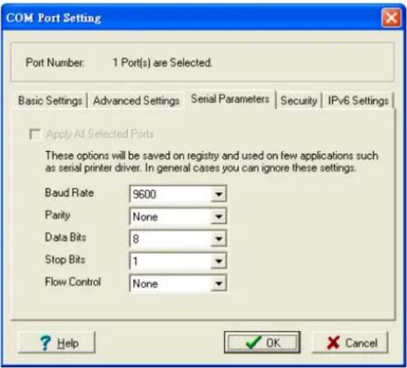
- Click the Security tab to configure security settings. Select the Enable Data Encryption option to enable data to be encrypted when transmitted over the COM ports. After selecting the encryption option, select the Keep connection option to start encryption on COM ports immediately, without restarting the COM ports. (If your application will open/close COM ports frequently and the NPort 6000 is only for one host, you can enable this option to speed up the opening/closing time. However, this will result in your host tying up the COM port so that other hosts cannot use it.) Select the Apply All Selected Ports option to enable the security settings to be applied to all COM ports.
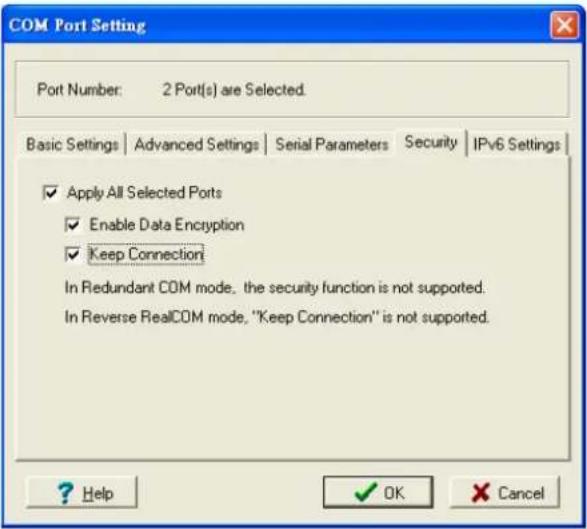
- Click the IPv6 Setting tab to configure the interface for Link-Local address mapping. When the global IPv6 address is used, this function can be ignored. When the Link-Local IPv6 address is used, users should select an interface for routing on interface index for address 1. The interface index for address 2 is for "redundant COM mode," which applies only to the CN2600 series.
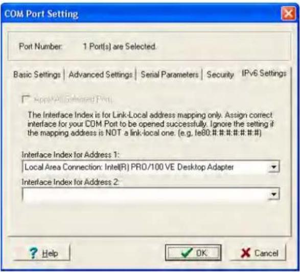
- To save the configuration to a text file, select Export from the COM Mapping menu. You will then be able to import this configuration file to another host and use the same COM Mapping settings in the other host.
![NPort Windows Driver Manager File COM Mapping Configuration View Help Add Ctrl+N Remove Ctrl+D Apply Undo Setting Setting Ctrl+C 168.127.254 950:966 [Port1] 2.168.127.254 951:967 [Port2] 3.168.127.254 952:968 [Port3] 4.168.127.254 953:969 [Port4] Export Import](/content/2026/06/1269850/images/22eb857c2e9166b64cdbe7880afb24955c75e0c05fb694f7c012ce563cbeec0c.jpg)
NPort Search Utility
Installing NPort Search Utility
- Click the INSTALL UTILITY button in the NPort Installation CD auto-run window to install NPort Search Utility. Once the program starts running, click Yes to proceed.
- When the Welcome screen opens, click Next to proceed with the installation.
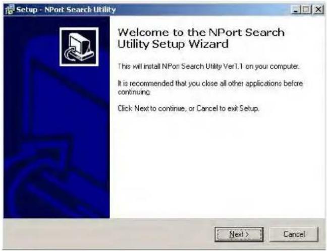
- Click Next to install program files to the default directory, or click Browse to select an alternate location.
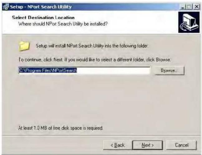
- Click Next to install the program's shortcuts in the appropriate Start Menu folder.
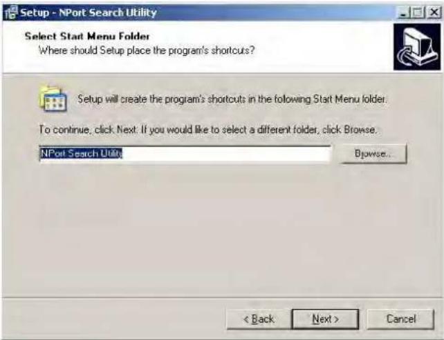
- Click Next to proceed with the installation. The installer then displays a summary of the installation options.
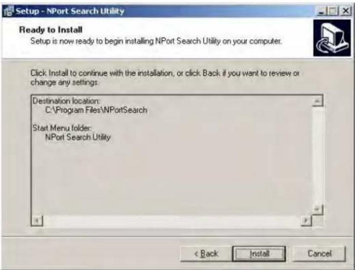
- Click Install to begin the installation. The setup window will report the progress of the installation. To change the installation settings, click Back and navigate to the previous screen.
- Click Finish to complete the installation of NPort Search Utility.
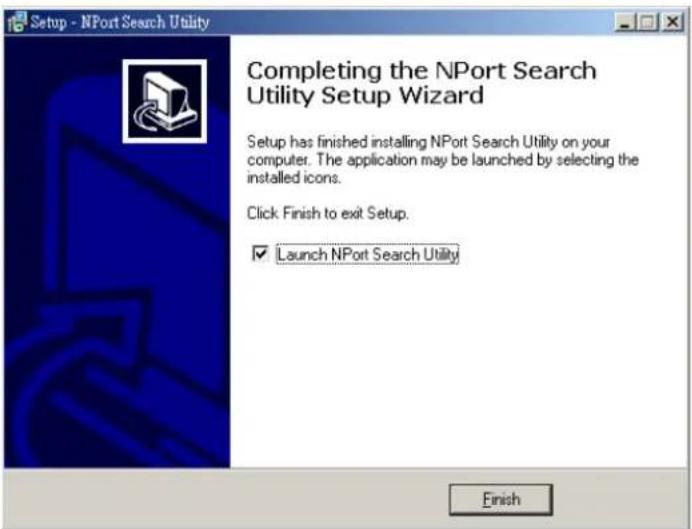
Configuring NPort Search Utility
The Broadcast Search function is used to locate all NPort 6000 servers that are connected to the same LAN as your computer. After locating an NPort 6000, you will be able to change its IP address.
Since the Broadcast Search function searches by MAC address and not IP address, all NPort 6000 servers connected to the LAN will be located, regardless of whether or not they are part of the same subnet as the host.
- Open NPort Search Utility and then click the Search icon.
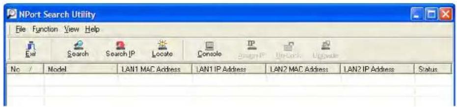
The Searching window indicates the progress of the search.
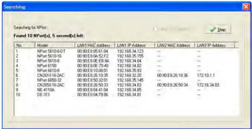
- When the search is complete, all NPort 6000 servers that were located will be displayed in the NPort Search Utility window.
| NPort Search Utility | |||||||
| File Function View Help | |||||||
| Exit | Search | Search IP | Locate | Console | IP Design IP | Unise | Update |
| No / | Model | LAN1 MAC Address | LAN1 IP Address | LAN2 MAC Address | LAN2 IP Address | Status | |
| 1 | NPort 5610-8-DT | 00:90:E8:05:61:04 | 192.168.34.123 | ... | ... | ||
| 2 | NPort 5610-16 | 00:90:E8:0A:52:F2 | 192.168.35.155 | ... | ... | ||
| 3 | NPort 5610-8 | 00:90:E8:0E:E8:8A | 192.168.34.84 | ... | ... | ||
| 4 | NPort 6150 | 00:90:E8:0E:79:40 | 192.168.34.82 | ... | ... | ||
| 5 | NPort 6610-8 | 00:90:E8:10:08:01 | 192.168.35.93 | ... | ... | ||
| 6 | CN2610-16-2AC | 00:90:E8:26:10:35 | 192.168.32.20 | 00:90:E8:26:10:36 | 172.10.1.1 | ||
| 7 | NPort 6650-32 | 00:90:E8:50:32:01 | 192.168.35.145 | ... | ... | ||
| 8 | CN2650-16-2AC | 00:90:E8:26:50:33 | 192.168.34.83 | 00:90:E8:26:50:34 | 172.16.34.83 | ||
| 9 | NE-4110A | 00:90:E8:04:41:04 | 192.168.34.85 | ... | ... | ||
| 10 | DE-311 | 00:90:E8:04:79:86 | 192.168.34.81 | ... | ... | ||
To modify the configuration of the highlighted NPort 6000, click on the Console icon to open the web console. This will take you to the web console, where you can make all configuration changes. Please refer to Chapter 5, Configuration with the Web Console, for information on how to use the web console.
Linux Real TTY Drivers
Basic Procedures
To map an NPort 6000 serial port to a Linux host's tty port, follow these instructions:
- Set up the NPort 6000. After verifying that the IP configuration works and you can access the NPort 6000 (by using ping, telnet, etc.), configure the desired serial port on the NPort 6000 to Real COM mode.
- Install the Linux Real tty driver files on the host
- Map the NPort serial port to the host's tty port
Hardware Setup
Before proceeding with the software installation, make sure you have completed the hardware installation. Note that the default IP address for the NPort 6000 is 192.168.127.254.
NOTE After installing the hardware, you must configure the operating mode of the serial port on your NPort 6000 to Real COM mode.
Installing Linux Real TTY Driver Files
NOTE The newest information, please refer to readme.txt on Linux Real TTY Friver
- Obtain the driver file from the included CD-ROM or the Moxa website, at http://www.moxa.com.
- Log in to the console as a super user (root).
- Execute cd / to go to the root directory.
- Copy the driver file npreal2xx.tgz to the / directory.
- Execute tar xvfz npreal2xx.tgz to extract all files into the system.
- Execute / tmp/ moxa/ mxinst.
For RedHat AS/ES/WS and Fedora Core1, append an extra argument as follows:
/ tmp/ moxa/ mxinst SP1
The shell script will install the driver files automatically.
- After installing the driver, you will be able to see several files in the /usr/lib/npreal2/ driver folder:
mxaddsvr (Add Server, mapping tty port)
mxdelsvr (Delete Server, unmapping tty port)
mxloadsvr (Reload Server)
mxmknod (Create device node/tty port)
mxrmnod (Remove device node/tty port)
mxuninst (Remove tty port and driver files)
At this point, you will be ready to map the NPort serial port to the system tty port.
Mapping TTY Ports
Make sure that you set the operation mode of the desired NPort 6000 serial port to Real COM mode. After logging in as a super user, enter the directory / usr/ lib/ npreal2/ driver and then execute mxaddsvr to map the target NPort serial port to the host tty ports. The syntax of mxaddsvr is as follows:
mxaddsvr [NPort IP Address] [Total Ports] ([Data port] [Cmd port])
The mxaddsvr command performs the following actions:
- Modifies npreal2d.cf.
- Creates tty ports in directory /dev with major & minor number configured in npreal2d.cf.
- Restarts the driver.
Mapping tty ports automatically
To map tty ports automatically, you may execute mxaddsvr with just the IP address and number of ports, as in the following example:
# cd / usr/ lib/ npreal2/ driver
# ./mxaddsvr 192.168.3.4 16
In this example, 16 tty ports will be added, all with IP 192.168.3.4, with data ports from 950 to 965 and command ports from 966 to 981.
Mapping tty ports manually
To map tty ports manually, you may execute m xaddsvr and manually specify the data and command ports, as in the following example:
# cd / usr/lib/ npreal2/ driver
# ./mxaddsvr 192.168.3.4 16 4001 966
In this example, 16 tty ports will be added, all with IP 192.168.3.4, with data ports from 4001 to 4016 and command ports from 966 to 981.
Removing Mapped TTY Ports
After logging in as root, enter the directory / usr/ lib/ npreal2/ driver and then execute mxdelsvr to delete a server. The syntax of mxdelsvr is:
mxdelsvr [IP Address]
Example:
# cd / usr/ lib/ npreal2/ driver
# ./ mxdelsvr 192.168.3.4
The following actions are performed when executing mxdelsvr:
- Modify npreal2d.cf.
- Remove the relevant tty ports in directory / dev.
- Restart the driver.
If the IP address is not provided in the command line, the program will list the installed servers and total ports on the screen. You will need to choose a server from the list for deletion.
Removing Linux Driver Files
A utility is included that will remove all driver files, mapped tty ports, and unload the driver. To do this, you only need to enter the directory /usr/lib/npreal2/ driver, then execute mxuninst to uninstall the driver. This program will perform the following actions:
- Unload the driver.
- Delete all files and directories in / usr/ lib/ npreal2
- Delete directory / usr/ lib/ npreal2
- Modify the system initializing script file.
The UNIX Fixed TTY Driver
NOTE The newest information, please refer to readme.txt on Fixed TTY Driver
Installing the UNIX Driver
- Log in to UNIX and create a directory for the Moxa TTY. To create a directory named / usr/ etc, execute the command:
<h1 id="mkdir-p-usr-etc">mkdir -p / usr/ etc</h1>
- Copy moxattyd.tar to the directory you created. If you created the /usr/ etc directory above, you would execute the following commands:
<h1 id="cp-moxattydtar-usr-etc">cp moxattyd.tar / usr/ etc</h1>
<h1 id="cd-usr-etc">cd / usr/ etc</h1>
- Extract the source files from the tar file by executing the command:
<h1 id="tar-xvf-moxattydtar">tar xvf moxattyd.tar</h1>
The following files will be extracted:
README.TXT
moxattyd.c --- source code
moxattyd.cf --- an empty configuration file
Makefile --- makefile
VERSION.TXT --- fixed tty driver version
FAQ.TXT
- Compile and Link
For SCO UNIX:
<h1 id="make-sco">make sco</h1>
For UnixWare 7:
<h1 id="make-svr5">make svr5</h1>
For UnixWare 2.1.x, SVR4.2:
<h1 id="make-svr42">make svr42</h1>
Configuring the UNIX Driver
Modify the configuration:
The configuration used by the moxattyd program is defined in the text file moxattyd.cf, which is in the same directory that contains the program moxattyd. You may use vi or any text editor to modify the file, as follows:
ttyp1 192.168.1.1 950
For more configuration information, view the file moxattyd.cf, which contains detailed descriptions of the various configuration parameters.
NOTE The "Device Name" depends on the OS. See the Device Naming Rule section in README.TXT for more information.
To start the moxattyd daemon after system bootup, add an entry into /etc/inittab, with the tty name you configured in moxattyd.cf, as in the following example:
ts:2:respawn:/usr/etc/moxattyd/moxattyd-t1
Device naming rule
For UnixWare 7, UnixWare 2.1.x, and SVR4.2, use:
pts/[n]
For all other UNIX operating systems, use:
ttyp[n]
Starting moxattyd
Execute the command init q or reboot your UNIX operating system.
Adding an additional server
- Modify the text file moxattyd.cf to add an additional server. User may use vi or any text editor to modify the file. For more configuration information, look at the file moxattyd.cf, which contains detailed descriptions of the various configuration parameters.
- Find the process ID (PID) of the program moxattyd.
ps -ef | grep moxattyd
- Update configuration of moxattyd program.
kill -USR1 [PID]
$$ (e. g., \text { if moxattyd PID } = 4 0 4, \text { kill -USR1 } 4 0 4) $$
This completes the process of adding an additional server.
The following topics are covered in this appendix:
□ Port Pinout Diagrams
➢ NPort 6150/6250/6450: RS-232/422/485 (male DB9)
NPort 6600: RS-232/422/485 (male RJ45)
□ Cable Wiring Diagrams
Ethernet Cables
Serial Cables (RS-232)
Serial Cables (RS-422/4-Wire RS-485)
Serial Cables (2-wire RS-485)
➢ Pin Assignments for DB9 and DB25 Connectors
Port Pinout Diagrams
NPort 6150/6250/6450: RS-232/422/485 (male DB9)
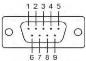
| PIN | RS-232 | RS-422/RS-485 (4W) | RS-485 (2W) |
| 1 | DCD TxD-(A) | - | |
| 2 | RXD TxD+(B) | - | |
| 3 | TXD RxD+(B) | Data+(B) | |
| 4 | DTR | RxD-(A) | Data-(A) |
| 5 | GND GND GND | ||
| 6 | DSR - | - | |
| 7 | RTS | - | - |
| 8 | CTS | - | - |
| 9 - | - | - |
NPort 6600: RS-232/422/485 (male RJ45)
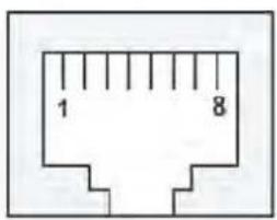
| PIN | RS-232 | RS-422/RS-485 (4W) | RS-485 (2W) |
| 1 | DSR - | - | |
| 2 | RTS | TxD+(B) | - |
| 3 | GND GND GND | ||
| 4 | TXD TxD-(A) - | ||
| 5 | RXD | RxD+(B) | Data+(B) |
| 6 | DCD | RxD-(A) | Data-(A) |
| 7 | CTS | - | - |
| 8 | DTR - | - |
Cable Wiring Diagrams
Ethernet Cables
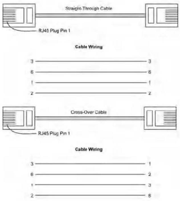
RJ45 (8-pin) to Female DB9
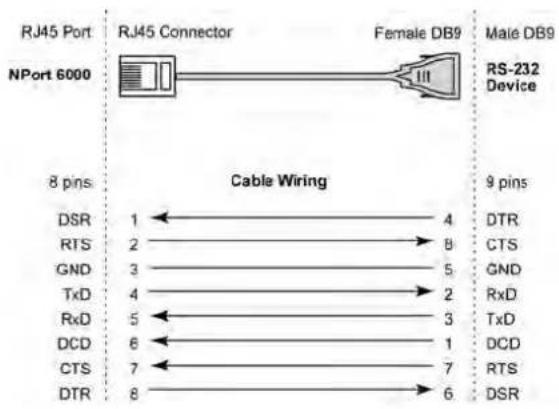
RJ45 (8-pin) to Male DB9
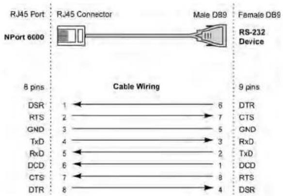
RJ45 (8-pin) to Female DB25
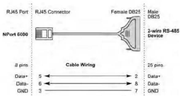
RJ45 (8-pin) to Male DB25
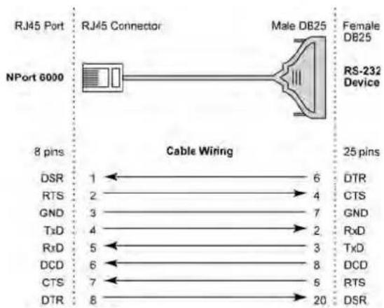
flowchart
graph LR
    A["RJ45 Port"] --> B["NPort 6000"]
    B --> C["RJ45 Connector"]
    C --> D["Male DB25"]
    C --> E["RS-232 Device"]
    D --> F["25 pins"]
    E --> G["8 pins"]
    H["DSR"] --> I["1"]
    J["RTS"] --> K["2"]
    L["GND"] --> M["3"]
    N["TxD"] --> O["4"]
    P["RxD"] --> Q["5"]
    R["DCD"] --> S["6"]
    T["CTS"] --> U["7"]
    V["DTR"] --> W["8"]
    X["DTR"] --> Y["6"]
    Z["CTS"] --> AA["7"]
    AB["RxD"] --> AC["2"]
    AD["TxD"] --> AE["3"]
    AF["DCD"] --> AG["8"]
    AH["CTS"] --> AI["5"]
    AJ["DTR"] --> AK["20"]
Serial Cables (RS-422/ 4-Wire RS-485)
RJ45 (8-pin) to Female DB9
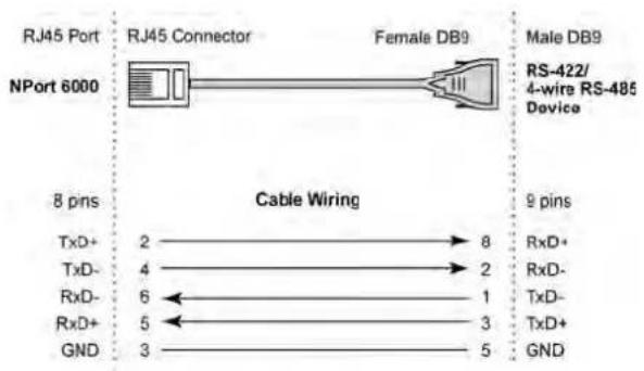
RJ45 (8-pin) to Male DB9
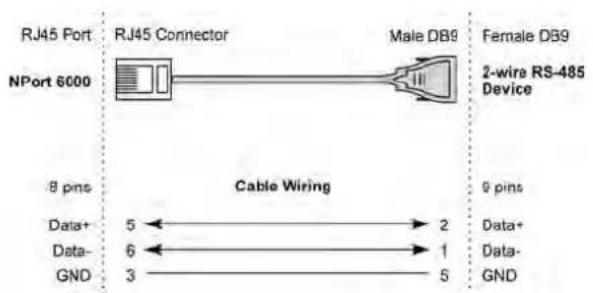
flowchart
graph LR
    A["RJ45 Port"] --> B["NPort 6000"]
    B --> C["RJ45 Connector"]
    C --> D["Male DB9"]
    D --> E["Female DB9"]
    F["8 pins"] --> G["Cable Wiring"]
    G --> H["Data+ 5"] --> I["2"]
    G --> J["Data- 6"] --> K["1"]
    G --> L["GND 3"] --> M["5"]
    N["2-wire RS-485 Device"] --> O["9 pins"]
RJ45 (8-pin) to Female DB25
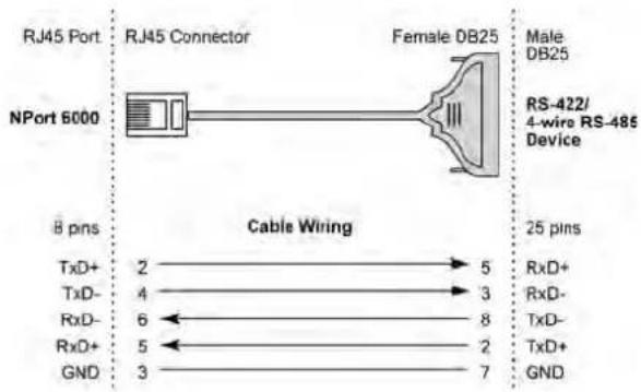
RJ45 (8-pin) to Male DB25
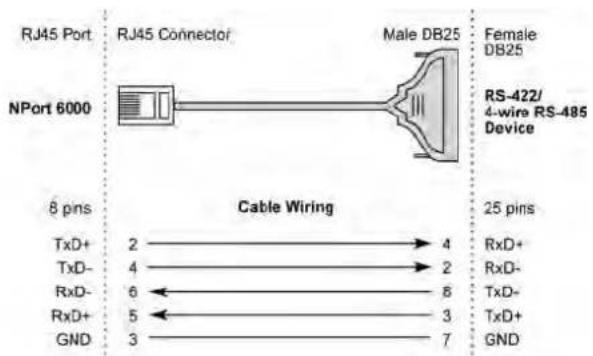
Serial Cables (2-wire RS-485)
RJ45 (8-pin) to Female DB9
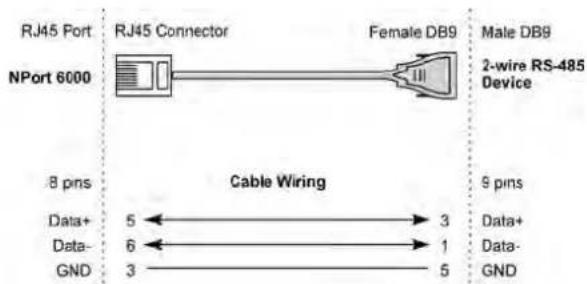
RJ45 (8-pin) to Male DB9
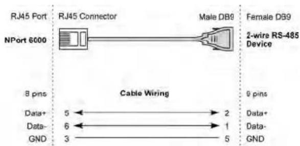
RJ45 (8-pin) to Female DB25
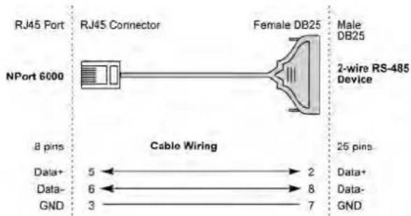
RJ45 (8-pin) to Male DB25
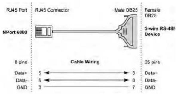
Pin Assignments for DB9 and DB25 Connectors
Pin Assignments for DB9 Male and Female Connectors
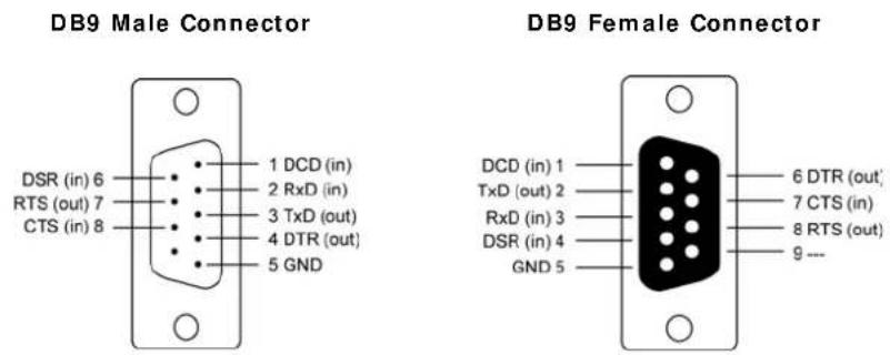
Pin Assignments for DB25 Male and Female Connectors
DB25 Male Connector
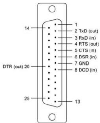
DB25 Female Connector
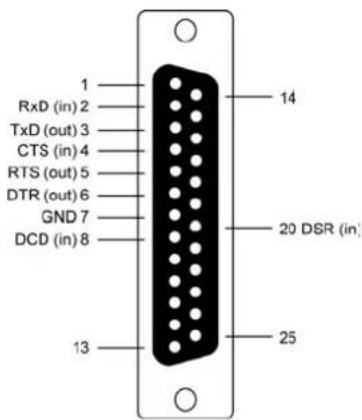
This appendix explains how to set up the environment to use RFC-2217 mode. RFC2217 defines general COM port control options based on the Telnet protocol and is used to allow the mapping of virtual COM ports to network ports. Any third-party driver that supports RFC-2217 can be used to implement the virtual COM port on the NPort 6000. The installation is as follows:
- In the NPort 6000 console, set up the desired serial port's operation mode as RFC2217 mode. By default, the first serial port on the NPort 6000 is assigned TCP port 4001, the second serial port is assigned TCP port 4002, and so on.
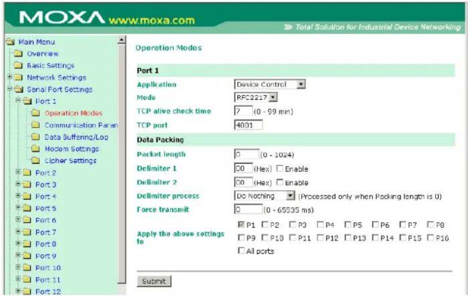
- Download and install a third-party driver that supports RFC-2217, such as Serial/IP COM Port Redirector (from Tactical Software).
- Using your third party's configuration program, map a COM port to the NPort 6000's IP address and the serial port's TCP port.
- Try opening the COM port that you just mapped. If you are able to open it, then the mapping was successful, and devices attached to the serial port on the NPort 6000 may be treated as if they were attached directly to the host computer.
This appendix explains how to use the NPort 6000 with DDNS. When the NPort 6000 receives its IP address from a DHCP (Dynamic Host Configuration Protocol) server, remote servers will be unable to access it using a fixed IP address. With DDNS (Dynamic Domain Name Server), a remote server can access the NPort 6000 using its domain name instead of its IP address.
Setting up the DDNS
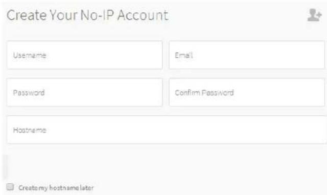
Currently, the NPort 6000 supports DNS service as provided by DynDNS.org and No-IP.com. Taking NO-IP.com as an example, you can easily register a hostname for your own use for free. For detailed information, visit http://www.noip.com/ or https://www.dyndns.com.
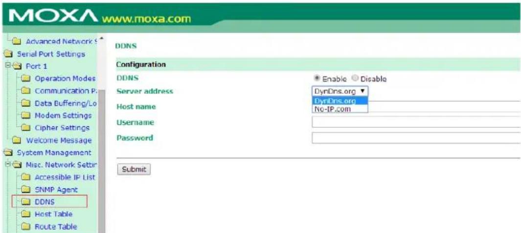
After you finish registering, you can fill in the host name, username, and password based on the service provider you have chosen.
For example, if you have registered the host name "moxanport6000.noip.me" with NO-IP.com, you choose "NO-IP.com" for the Server address, input "moxanport6000.noip.me" for host name, input your username and password on "NP-IP.com", and then click Submit. After doing so, when a remote server wants to access this NPort 6000, it can simply use "moxanport6000.noip.me" instead of its IP address.
In this appendix, we provide a list of well-known port numbers that may cause network problems if you set the NPort 6000 to one of these ports. Refer to RFC 1700 for well-known port numbers or to the following introduction from the IANA:
The port numbers are divided into three ranges: the Well-Known Ports, the Registered Ports, and the Dynamic and/or Private Ports.
The Well-Known Ports range from 0 through 1023.
The Registered Ports range from 1024 through 49151.
The Dynamic and/or Private Ports range from 49152 through 65535.
The Well-nown Ports are assigned by the IANA, and on most systems, they can only be used by system processes or by programs executed by privileged users. The following table shows famous port numbers among the listed well-known port numbers. For more details, please visit the IANA website at http://www.iana.org/assignments/port-numbers.
| TCP Socket Application Service | |
| 0 Reserved | |
| 1 TCP Port Service Multiplexer | |
| 2 Management Utility | |
| 7 Echo | |
| 9 Discard | |
| 11 Active Users (systat) | |
| 13 Daytime | |
| 15 Netstat | |
| 20 FTP data port | |
| 21 FTP control port | |
| 23 Telnet | |
| 25 SMTP (Simple Mail Transfer Protocol) | |
| 37 Time (Time Server) | |
| 42 Host name server (names server) | |
| 43 Whois (nickname) | |
| 49 Login Host Protocol (login) | |
| 53 Domain Name Server (domain) | |
| 79 Finger protocol (finger) | |
| 80 World Wide Web (HTTP) | |
| 119 | Network News Transfer Protocol (NNTP) |
| 123 Network Time Protocol | |
| 213 IPX | |
| 160 to 223 Reserved for future use | |
| UDP Socket Application Service | |
| 0 Reserved | |
| 2 Management Utility | |
| 7 Echo | |
| 9 Discard | |
| 11 Active Users (systat) | |
| 13 Daytime | |
| 35 Any private printer server | |
| 39 Resource Location Protocol | |
| 42 Host name server (names server) | |
| 43 Whois (nickname) | |
| 49 Login Host Protocol (login) | |
| 53 | Domain Name Server (domain) |
| 69 Trivial Transfer Protocol (TETP) | |
| 70 Gopher Protocol | |
| 79 Finger Protocol | |
| 80 World Wide Web (HTTP) | |
| 107 Remote Telnet Service | |
| 111 Sun Remote | Procedure Call (Sunrpc) |
| 119 | Network News Transfer Protocol (NNTP) |
| 123 Network Time Protocol (NTP) | |
| 161 | SNMP (Simple Network Management Protocol) |
| 162 SNMP Traps | |
| 213 IPX (used for IP Tunneling) | |
SNMP Agents with MIB II & RS-232 Like Groups
The NPort 6000 has built-in SNMP (Simple Network Management Protocol) agent software that supports SNMP Trap, RFC1317 and RS-232-like groups, and RFC 1213 MIB-II. The following table lists the standard MIB-II groups as well as the variable implementation for the NPort 6000.
The following topics are covered in this appendix:
☐ RFC1213 MIB-II Supported SNMP Variables
☐ RFC1317 RS-232 Like Groups
□ Moxa-NP6000-MIB
RFC1213 MIB-II Supported SNMP Variables
| System MIB | Interfaces MIB | IP MIB | ICMP MIB |
| sysDescr | ifNumber | ipForwarding | icmpInMsgs |
| sysObjectID | ifIndex | ipDefaultTTL | icmpInErrors |
| sysUpTime | ifDescr | ipInReceives | icmpInDestUnreachs |
| sysContact | ifType | ipInHdrErrors | icmpInTimeExcds |
| sysName | ifMtu | ipInAddrErrors | icmpInParmProbs |
| sysLocation | ifSpeed | ipForwDatagrams | icmpInSrcQuenchs |
| sysServices | ifPhysAddress | ipInUnknownProtos | icmpInRedirects |
| ifAdminStatus | ipInDiscards | icmpInEchos | |
| ifOperStatus | ipInDelivers | icmpInEchoReps | |
| ifLastChange | ipOutRequests | icmpInTimestamps | |
| ifInOctets | ipOutDiscards | icmpTimestampReps | |
| ifInUcastPkts | ipOutNoRoutes | icmpInAddrMasks | |
| ifInNUcastPkts | ipReasmTimeout | icmpInAddrMaskReps | |
| ifInDiscards | ipReasmReqds | icmpOutMsgs | |
| ifInErrors | ipReasmOKs | icmpOutErrors | |
| ifInUnknownProtos | ipReasmFails | icmpOutDestUnreachs | |
| ifOutOctets | ipFragOKs | icmpOutTimeExcds | |
| ifOutUcastPkts | ipFragFails | icmpOutParmProbs | |
| ifOutNUcastPkts | ipFragCreates | icmpOutSrcQuenchs | |
| ifOutDiscards | ipAdEntAddr | icmpOutRedirects | |
| ifOutErrors | ipAdEntIfIndex | icmpOutEchos | |
| ifOutQLen | ipAdEntNetMask | icmpOutEchoReps | |
| ifSpecific | ipAdEntBcastAddr | icmpOutTimestamps | |
| ipAdEntReasmMaxSize | icmpOutTimestampReps | ||
| ipRouteDest | icmpOutAddrMasks | ||
| ipRouteIfIndex | icmpOutAddrMaskReps | ||
| ipRouteMetric1 | |||
| ipRouteMetric2 | |||
| ipRouteMetric3 | |||
| ipRouteMetric4 | |||
| ipRouteNextHop | |||
| ipRouteType | |||
| ipRouteProto | |||
| ipRouteAge | |||
| ipRouteMask | |||
| ipRouteMetric5 | |||
| ipRouteInfo | |||
| ipNetToMediaIfIndex | |||
| ipNetToMediaPhysAddress | |||
| ipNetToMediaNetAddress | |||
| ipNetToMediaType | |||
| ipRoutingDiscards | |||
| Address Translation MIB | TCP MIB UDP MIB SN | MP MIB | |
| atIfIndex | tcpRtoAlgorithm | udpInDatagrams | snmpInPkts |
| atPhysAddress | tcpRtoMin | udpNoPorts | snmpOutPkts |
| atNetAddress | tcpRtoMax | udpInErrors | snmpInBadVersions |
| tcpMaxConn | udpOutDatagrams | snmpInBadCommunityNames | |
| tcpActiveOpens | udpLocalAddress | snmpInBadCommunityUses | |
| tcpPassiveOpens | udpLocalPort | snmpInASNParseErrs | |
| tcpAttemptFails | snmpInTooBigs | ||
| tcpEstabResets | snmpInNoSuchNames | ||
| tcpCurrEstab | snmpInBadValues | ||
| tcpInSegs | snmpInReadOnly | ||
| tcpOutSegs | snmpInGenErrs | ||
| tcpRetransSegs | snmpInTotalReqVars | ||
| tcpConnState | snmpInTotalSetVars | ||
| tcpConnLocalAddress | snmpInGetRequests | ||
| tcpConnLocalPort | snmpInGetNexts | ||
| tcpConnRemAddress | snmpInSetRequests | ||
| tcpConnRemPort | snmpInGetResponses | ||
| tcpInErrs | snmpInTraps | ||
| tcpOutRsts | snmpOutTooBigs | ||
| snmpOutNoSuchNames | |||
| snmpOutBadValues | |||
| snmpOutGenErrs | |||
| snmpOutGetRequests | |||
| snmpOutGetNexts | |||
| snmpOutSetRequests | |||
| snmpOutGetResponses | |||
| snmpOutTraps | |||
| snmpEnableAuthenTraps | |||
| snmpSilentDrops | |||
| snmpProxyDrops | |||
RFC1317 RS-232 Like Groups
| RS-232 MIB | Async Port MIB |
| rs232Number | rs232AsyncPortIndex |
| rs232PortIndex | rs232AsyncPortBits |
| rs232PortType | rs232AsyncPortStopBits |
| rs232PortInSigNumber | rs232AsyncPortParity |
| rs232PortOutSigNumber | |
| rs232PortInSpeed | |
| rs232PortOutSpeed |
| Input Signal MIB | Output Signal MIB |
| rs232InSigPortIndex | rs232OutSigPortIndex |
| rs232InSigName | rs232OutSigName |
| rs232InSigState | rs232OutSigState |
Moxa-NP6000-MIB
| overview | basicSetting | networkSetting | opModeSetting |
| modelName | serverName | ipConfiguration | portIndex |
| serialNumber | serverLocation | sysIpAddress | portApplication |
| firmwareVersion | timeZone | netMask | portMode |
| macAddress | localTime | defaultGateway | |
| viewLanSpeed | timeserver | dnsServer1IpAddr | |
| viewLanModuleSpeed | dnsServer2IpAddr | ||
| upTime | pppoeUserAccount | ||
| moduleType | pppoePassword | ||
| winsFunction | |||
| winsServer | |||
| lan1Speed | |||
| routingProtocol | |||
| gratuitousArp | |||
| gratuitousArpSendPerios |
| deviceControl Mode | socket Mode |
| deviceControlTcpAliveCheck | socketTcpAliveCheck |
| deviceControlMaxConnection | socketInactivityTime |
| deviceControlIgnoreJammedIp | socketMaxConnection |
| deviceControlAllowDriverControl socketIgnoreJammedIp | |
| deviceControlSecure | socketAllowDriverControl |
| deviceControlLocalTcpPort | socketSecure |
| deviceControlConnectionDownRTS | socketLocalTcpPort |
| deviceControlConnectionDownDTR | socketCmdPort |
| socketTcpServerConnectionDownRTS | |
| socketTcpServerConnectionDownDTR | |
| socketTcpClientDestinationAddress1 | |
| socketTcpClientDestinationPort1 | |
| socketTcpClientDestinationAddress2 | |
| socketTcpClientDestinationPort2 | |
| socketTcpClientDestinationAddress3 | |
| socketTcpClientDestinationPort3 | |
| socketTcpClientDestinationAddress4 | |
| socketTcpClientDestinationPort4 | |
| socketTcpClientDesignatedLocalPort1 | |
| socketTcpClientDesignatedLocalPort2 | |
| socketTcpClientDesignatedLocalPort3 | |
| socketTcpClientDesignatedLocalPort4 | |
| socketTcpClientConnectionControl | |
| socketUdpDestinationAddress1Begin | |
| socketUdpDestinationAddress1End | |
| socketUdpDestinationPort1 | |
| socketUdpDestinationAddress2Begin | |
| socketUdpDestinationAddress2End | |
| socketUdpDestinationPort2 | |
| socketUdpDestinationAddress3Begin | |
| socketUdpDestinationAddress3End | |
| socketUdpDestinationPort3 | |
| deviceControl Mode socket Mode | socketUdpDestinationAddress4Begin |
| socketUdpDestinationAddress4End | |
| socketUdpDestinationPort4 | |
| socketUdpLocalListenPort |
| pairConnection Mode | ethernetModem Mode |
| pairConnectionTcpAliveCheck | ethernetModemTcpAliveCheck |
| pairConnectionSecure ethernetModemTcpPort | |
| pairConnectionDestinationAddress | |
| pairConnectionDestinationPort | |
| pairConnectionTcpPort |
| terminal Mode reverseTerminal Mode | |
| terminalTcpAliveCheck reverseTerminalTcpAliveCheck | |
| terminalInactivityTime reverseTerminalInactivityTime | |
| terminalAutoLinkProtocol reverseTerminalTcpPort | |
| terminalPrimaryHostAddress reverseTerminalAuthenticationType | |
| terminalSecondHostAddress reverseTerminalMapKeys | |
| terminalTelnetTcpPort | |
| terminalSshTcpPort | |
| terminalType | |
| terminalMaxSessions | |
| terminalChangeSession | |
| terminalQuit | |
| terminalBreak | |
| terminalInterrupt | |
| terminalAuthenticationType | |
| terminalAutoLoginPrompt | |
| terminalPasswordPrompt | |
| terminalLoginUserName | |
| terminalLoginPassword | |
| printer Mode | dial Mode | dataPacking |
| printerTcpAliveCheck | dialTERMBINMode | portPacketLength |
| printerTcpPort | dialPPPDMode | portDelimiter1Enable |
| printerGroup | dialSLIPDMode | portDelimiter1 |
| printerQueueNameRaw | dialAuthType | portDelimiter2Enable |
| printerQueueNameASCII | dialDisconnectBy | portDelimiter2 |
| printerAppendFromFeed | dialDestinationIpAddress | portDelimiterProcess |
| dialSourceIpAddress | portForceTransmit | |
| dialIpNetmask | ||
| dialTcpIpCompression | ||
| dialInactivityTime | ||
| dialLinkQualityReport | ||
| dialOutgoingPAPID | ||
| dialPAPPassword | ||
| dialIncomingPAPCheck | ||
| com Param Setting | dataBuffering | modem Setting |
| portAlias | portBufferingEnable | portEnableModem |
| portInterface | portBufferingLocation | portInitialString |
| portBaudRate | portBufferingSDFileSize | portDialUp |
| portBaudRateManual | portSerialDataLoggingEnable | portPhoneNumber |
| portDataBits | ||
| portStopBits | ||
| portParity | ||
| portFlowControl | ||
| portFIFO |
| welcomeMessage | sysManagement |
| portEnableWelcomeMessage | enableAccessibleIpList |
| portMessage | accessibleIpListIndex |
| activeAccessibleIpList | |
| accessibleIpListAddress | |
| accessibleIpListNetmask | |
| snmpEnable | |
| snmpContactName | |
| snmpLocation | |
| dDNSEnable | |
| dDNSServerAddress | |
| dDNSHostName | |
| dDNSUserName | |
| dDNSPassword | |
| hostTableIndex | |
| hostName | |
| hostIpAddress | |
| routeTableIndex | |
| gatewayRouteTable | |
| destinationRouteTable | |
| netmaskRouteTable | |
| metricRouteTable | |
| interfaceRouteTable | |
| userTableIndex | |
| userNameUserTable | |
| passwordUserTable | |
| phoneNumberUserTable | |
| radiusServerIp | |
| radiusKey | |
| udpPortAuthenticationServer | |
| radiusAccounting | |
| sysLocalLog | |
| networkLocalLog | |
| configLocalLog | |
| opModeLocalLog | |
| mailWarningColdStart | |
| mailWarningWarmStart | |
| mailWarningAuthFailure | |
| mailWarningIpChanged | |
| mailWarningPasswordChanged | |
| trapServerColdStart | |
| welcomeMessage sysManagement | trapServerWarmStart |
| trapServerAuthFailure | |
| alarmServerEthernet1LinkDown | |
| alarmServerEthernet2LinkDown | |
| alarmServerEthernet3LinkDown | |
| mailDCDchange | |
| trapDCDchange | |
| alarmDCDchange | |
| mailDSRchange | |
| trapDSRchange | |
| alarmDSRchange | |
| emailWarningMailServer | |
| emailRequiresAuthentication | |
| emailWarningUserName | |
| emailWarningPassword | |
| emailWarningFromEmail | |
| emailWarningFirstEmailAddr | |
| emailWarningSecondEmailAddr | |
| emailWarningThirdEmailAddr | |
| emailWarningFourthEmailAddr | |
| snmpTrapReceiverIp | |
| trapVersion | |
| httpConsole | |
| httpsConsole | |
| telnetConsole | |
| sshConsole | |
| lcmReadOnlyProtect | |
| resetButtonFunction | |
| loadFactoryDefaultSetting |
| sysStatus | saveConfiguration | restart |
| remoteIpIndex | saveConfig | restartPorts |
| monitorRemoteIp restartSystem | ||
| monitorTxCount | ||
| monitorRxCount | ||
| monitorTxTotalCount | ||
| monitorRxTotalCount | ||
| monitorDSR | ||
| monitorDTR | ||
| monitorRTS | ||
| monitorCTS | ||
| monitorDCD | ||
| monitorErrorCountFrame | ||
| monitorErrorCountParity | ||
| monitorErrorCountOverrun | ||
| monitorErrorCountBreak | ||
| monitorBaudRate | ||
| monitorDataBits | ||
| monitorParity | ||
| monitorRTSCTSFlowControl | ||
| monitorXONXOFFFlowControl | ||
| monitorFIFO | ||
| monitorInterface | ||
| relayOutputEthernet1LinkDown | ||
| ethernet1LinkDownAcknowledge | ||
| relayOutputEthernet2LinkDown | ||
| ethernet2LinkDownAcknowledge | ||
| relayOutputEthernet3LinkDown | ||
| ethernet3LinkDownAcknowledge | ||
| portDCDChangedStatus | ||
| portDCDChangedAcknowledge | ||
| portDSRChangedStatus | ||
| portDSRChangedAcknowledge |
Managing diverse serial lines and modem pools for large numbers of users creates the need for significant administrative support. Since modem pools are links to the outside world, careful attention must be paid to security, authorization, and accounting. This can best be achieved by managing a single database of users allowing authentication (verifying user names and passwords) as well as configuration of information that details the type of service to deliver to the user (e.g. SLIP, PPP, Telnet, and rlogin). The NPort 6000 supports the RADIUS protocol, which requires only one database for remote user management.
The following topics are covered in this appendix:
□ What is RADIUS?
Definition
▶ Client/Server Architecture
☐ Setting up the NPort 6000
Setting up the RADIUS Server IP Address
Serial Port Configuration
Setting up UNIX Hosts
☐ Setting up Windows NT Hosts
☐ Setting up Windows 2000 Hosts
☐ Setting up Windows 2003 Hosts
What is RADIUS?
Definition
Remote Authentication Dial-up User Service, or RADIUS, is the standard for centralizing the authentication, authorization, and accounting of remote access users.
Here is a brief description of how RADIUS works: When a user dials in to a remote access device, that device communicates with the central RADIUS server to determine if the user is authorized to connect to the LAN. The RADIUS server performs the authentication and responds with the result—either accept or reject. If the user is accepted, the remote access server routes the user onto the network; if not, the server will terminate the user's connection. The RADIUS server also provides accounting services if supported by the remote access server.
With RADIUS, a network manager or ISP only needs to maintain a single, central database against which all remote user authentications take place. This greatly eases the management burden associated with administering a large number of dial-in users.
Client/ Server Architecture
RADIUS is a type of client-server software. Communication servers such as the NPort 6000 play an active role, whereas RADIUS servers are passive.
When a remote host is connected to the NPort 6000, the host is prompted to enter a user ID and password.
After receiving the user ID and password, the NPort 6000 sends the information to a defined RADIUS server. Up to this point, the remote user is still unable to access the network.
The RADIUS server compares the user ID and password with its internal database and responds through the network, either accepting or rejecting the connection attempt.
If the NPort 6000 receives the "accept" message from the RADIUS server, the remote user is allowed to access the network. Otherwise, the NPort 6000 will either terminate the connection or attempt to connect again after a specified duration of time.
Setting up the NPort 6000
Setting up the RADIUS Server IP Address
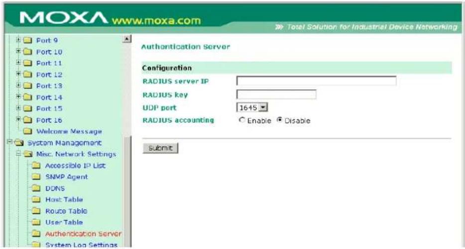
RADIUS server IP: This is the IP address of the RADIUS server.
RADIUS key: This is the password that is used to access the RADIUS server IUS server
UDP port: This is the RADIUS server's assigned UDP port.
RADIUS accounting: This field enables or disables RADIUS accounting.
Serial Port Configuration
RADIUS is an effective authentication method for dial-up services. In addition to dial-up services (PPP, SLIP, and Dynamic), the NPort 6000 supports RADIUS settings for terminal applications and console management application. You will see it as an option for Authentication type when configuring the port's operation mode. Please refer to Chapter 7, Configuring Serial Port Operation Modes, for detailed information and configuration instructions.
Setting up UNIX Hosts
Moxa recommends the FreeRADIUS server for UNIX users. FreeRADIUS is the premiere open-source RADIUS server and is one of the top five RADIUS servers in use worldwide. It is effective for both embedded systems with small amounts of memory and for systems with millions of users. It is fast, flexible, and configurable, and it supports more authentication protocols than many commercial servers.
The server is released under the GNU General Public License (GPL), which means that it is free to download and install. FreeRADIUS can be downloaded from the following website:
http://www.freeradius.com/
Setting up Windows NT Hosts
- Install Windows NT OPTION PACK 4.0 on the Windows NT server.
- Open Start → Programs → Windows NT 4.0 Option Pack → Microsoft Internet Information Server → Management Console Manger.
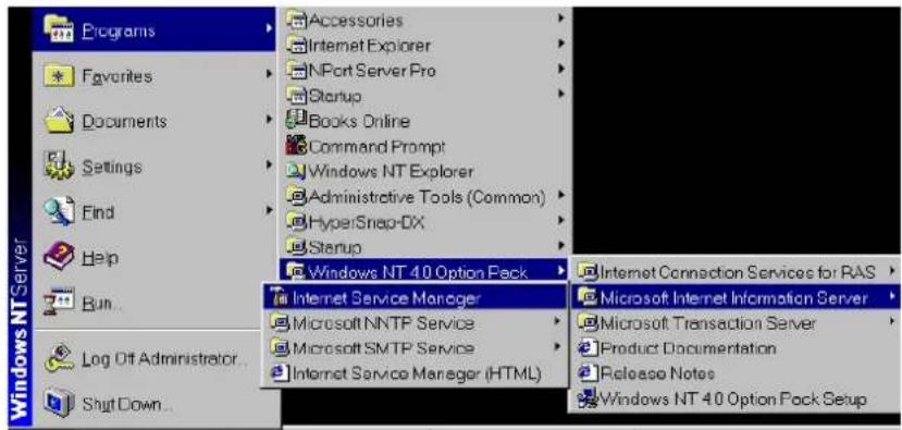
- Go to Console Root → Internet Information Server (in the left pane). Your computer's name should be visible.
- Find your computer's name in the left panel and click on it, after which you will see RADIUS in the right information window.
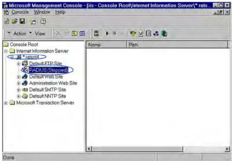
- Right click RADIUS in the left information window and then select Properties.
![Microsoft Management Console - [iis - Console Root\Internet Information Server\* rats...] Console Window Help Action View Console Root Internet Information Server * ratsnt4 Default FTP Site RADIUS (Stop ps) Default Web Site Administration W Default SMTP Site Default NNTP Site Microsoft Transaction S Name Path Start Stop Focus Properties New Task New window from here Refresh Scope Pane Description Bar Properties for the selected item](/content/2026/06/1269850/images/1433c2005f977c5d083f994a001a97dedad8c8b7693e20e3137c9fe4b4be6144.jpg)
- Select Service. Verify that the RADIUS ports assignments match your configuration.
[Authentication] 1645 or 1812
[Accounting] 1646 or 1813
- Select Client and then click Add. Enter the NPort 6000's IP address in the IP address field. Enter the NPort 6000's RADIUS key in the password field. This must match the RADIUS key that you set in the NPort 6000 console.
![Internet Authentication Service Properties - ratsat4 Services | Logging | Clients | Profiles | Clients are network access device password (shared secret) with e Client Information Authentication requests can be n Client Location Client Location IP address: 192 168 205 200 DNS name: Password (shared secret): 1234 Add... Add... Talset-192.168.205.200 Done: Edit Terminal Date MoxaServer U2.00 Info [Adv.] Host_table Route_table User_table Quit Examine/modify async server advance configuration ESC-back to menu Enter: select RADIUS server IP [192.168.205.101] RADIUS key [1234] UDP port [1:1645 2:1612] [1] Enable RADIUS accounting [yes] SNMP community name [public ] SNMP trap server IP address [ ] Ethernet IP forwarding [no ] Routing protocol [None ] TCP retransmission timeout [ ] $IO data transfer timeout [ ]](/content/2026/06/1269850/images/86e4656d380ca46afe96b1619d823af0cb02c02dff85611fa1699b009beb8e78.jpg)
- Click Apply.
- Right click RADIUS in the left information window and select Start. You will now see that RADIUS is running.
Setting up Windows 2000 Hosts
- Open Start → Programs → Administrative Tools → Routing and Remote Access.
- Right click Server (Local) and select Configure and Enable Routing and Remote Access. Click Next to continue.
- Select Remote access server and click Next to continue.
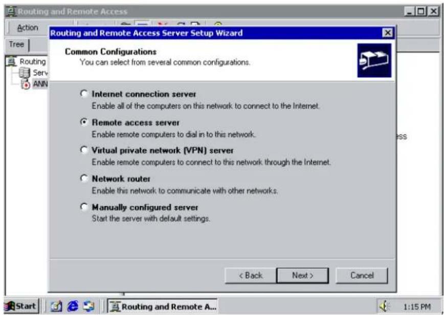
- Select Set up an advanced remote access server and click Next to continue.
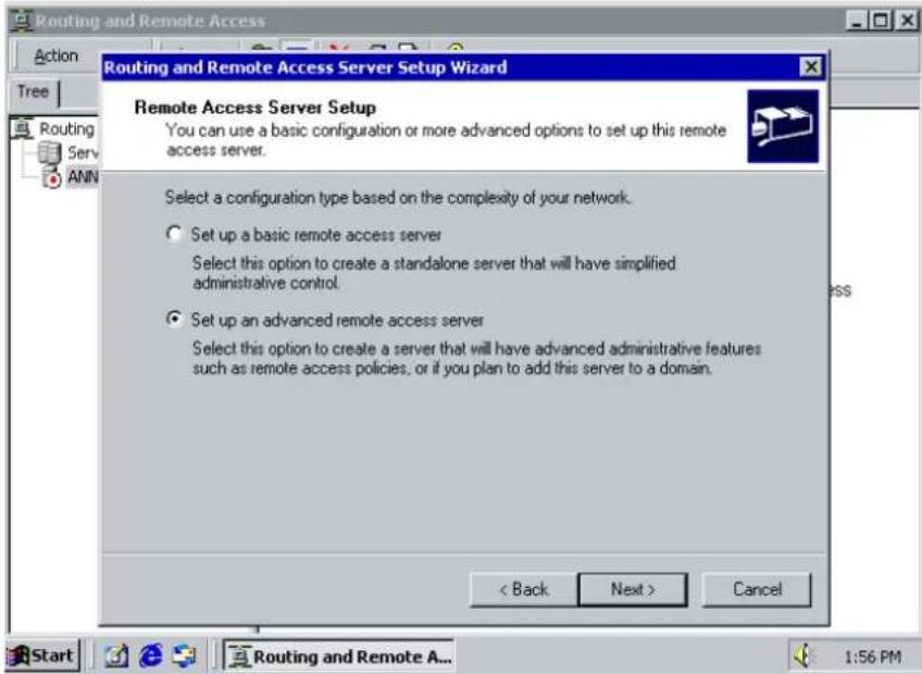
- Select TCP/IP protocol, then click Next to continue.
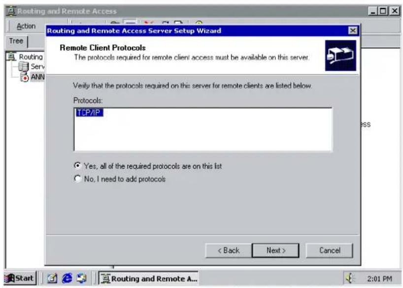
- Specify your IP address as shown on the following screens:
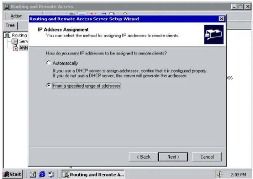
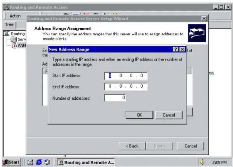
- Select Yes, I want to use a RADIUS server and click Next.
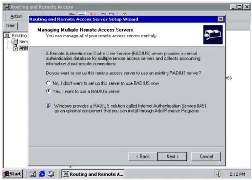
Setting up Windows 2003 Hosts
Windows 2003 uses the IAS service instead of the RADIUS service. For this reason, you need to install the IAS service to use RADIUS with Windows 2003 (The IAS service will not be installed by default).
- Click Start → Add or Remove Programs → Add/ Remove Windows Components.
- With Windows Components selected, choose Networking Services.
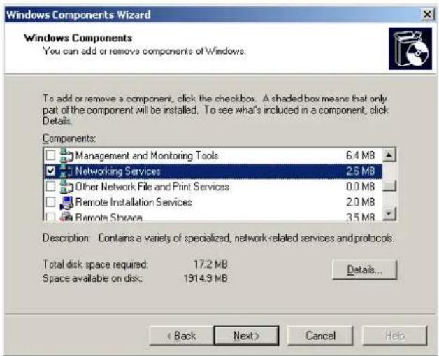
- Select Details and then select Internet Authentication Service. Continue clicking OK until the installation is complete.
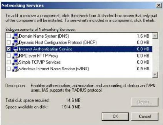
- After the installation is complete, click Administrative Tools and run the Internet Authentication Service. This will open the following window.
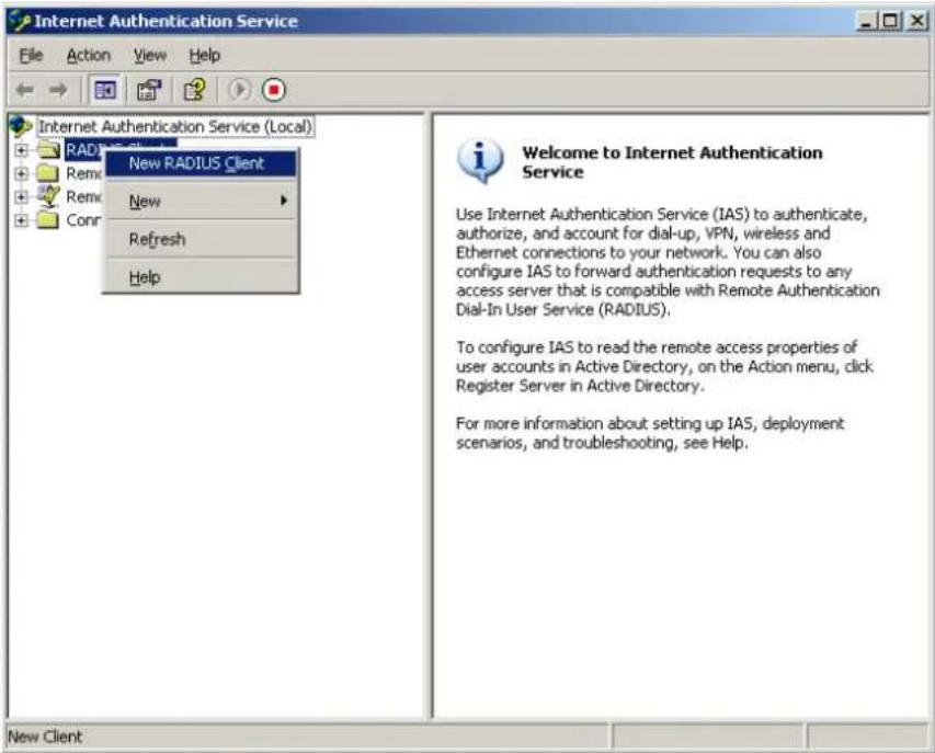
- Select New RADIUS Client to add a new RADIUS client. You will then be able to begin using this function.
- NPort 6000 Series User's Manual
- Copyright Notice
- Trademarks
- Disclaimer
- Technical Support Contact Information
- Moxa Americas
- Moxa Europe
- Moxa India
- Moxa China (Shanghai office)
- Moxa Asia-Pacific
- Getting Started 2-1
- Initial IP Address Configuration.... 3-1
- Introducing Serial Port Operation Modes 4-1
- Configuration with the Web Console 5-1
- Overview
- Package Checklist
- NPort 6610/6650
- Standard Accessories for the NPort 6610 and NPort 6650
- Cable Accessories for the NPort 6610 and NPort 6650 (can be purchased separately)
- Extension Modules for the NPort 6450 and NPort 6600 (can be purchased separately)
- NPort 6150, NPort 6250, and NPort 6450
- Standard Accessories for the NPort 6150 and NPort 6250
- DIN-Rail Accessories for the NPort 6150, NPort 6250, and NPort 6450 (can be purchased separately)
- Product Features
- Product Selection Chart
- Product Specifications
- NPort 6150
- Physical Characteristics
- Environmental Limits
- Power Requirements
- Standards and Certifications
- MTBF (mean time between failures)
- NPort 6250/6250-S-SC/6250-M-SC
- NPort 6450
- Ethernet Interface
- Serial Interface
- Serial Communication Parameters
- Serial Signals
- Memory Expansion Slot
- Software
- Operation Modes
- Applications
- Weight:
- Dimensions:
- Operating Temperature:
- Storage Temperature:
- Input Voltage:
- Input Current:
- EMS:
- Reliability
- Panel Layout
- ☐ Panel, DIN-Rail, and Rack Mounting
- □ Connecting the Hardware
- NPort 6150/6250
- Panel, DIN-Rail, and Rack Mounting
- Wall or Cabinet Mounting
- DIN-Rail Mounting
- Rack Mounting
- Connecting the Hardware
- Wiring Requirements
- ATTENTION
- Connecting the NPort 6600 VDC's Power
- Grounding the NPort 6600 VDC
- Connecting to the Network
- Connecting to a Serial Device
- LED Indicators
- Adjustable Pull High/ Low Resistors for the RS-485 Port
- NPort 6150/6250/6450 Jumpers
- Static and Dynamic IP Addresses
- Factory Default IP Address
- Configuration Options
- NPort Search Utility
- Web Console
- LCM Console/ Front Panel (NPort 6610, 6650, and 6450 only)
- ARP
- Telnet Console
- Serial Console
- Guide to NPort 6000 Modes
- Device-Control Applications
- Real COM and Secure Real COM Modes
- Reverse Real COM Mode
- RFC2217 Mode
- Socket Applications
- TCP Server and Secure TCP Server Modes
- TCP Client and Secure TCP Client Modes
- UDP Mode
- Pair Connection and Secure Pair Connection Modes
- Ethernet Modem Mode
- Terminal Applications
- Terminal ASCII Mode
- Terminal BIN Mode
- SSH Mode
- Reverse Terminal Applications
- Reverse Telnet
- Reverse SSH
- Dial In/ Out Modes
- Disabled Mode
- □ Using Your Web Browser
- □ Web Console Navigation
- □ Basic Settings
- □ Network Settings
- Using Your Web Browser
- Browser Cookie Settings
- Trusted Site Settings
- Opening the Web Console
- Web Console Navigation
- Basic Settings
- Server Settings
- Time Settings
- Network Settings
- Basic Network Settings
- What is IPv6?
- IPv6 Gateway
- Advanced Network Settings
- What is RIP?
- Configuring the Route Table
- NM-TX01, NM-TX02, NM-FX01-M-SC, NM-FX01-S-SC, NM-FX02-M-SC, NM-FX02-S-SC
- Using Ethernet Redundancy
- NOTE
- The STP/ RSTP Concept
- What is STP?
- How STP Works
- STP Requirements
- STP Calculation
- STP Configuration
- STP Reconfiguration
- Differences between RSTP and STP
- STP Example
- Configuring RSTP
- Configuration Limits of RSTP/ STP
- Configuring Turbo Ring
- The Turbo Ring Concept
- Determining the Redundant Path of a "Turbo Ring" Ring
- When the number of NPort 6000 units in the Turbo Ring is even.
- When the number of NPort 6000 units in the Turbo Ring is odd.
- Turbo Ring Settings
- Configuring Turbo Ring 2
- □ Port Setting Basics
- □ Device Control Applications
- □ Socket Applications
- □ Pair Connection Mode
- ☐ Ethernet Modem Mode
- ☐ Terminal Applications
- ☐ Reverse Terminal Applications
- □ Printer Applications
- ☐ Dial In/ Out Applications
- □ Disabled Mode
- Port Setting Basics
- Device Control Applications
- Real COM Mode
- Command by command operation (default
- TCP Server Mode
- Command by command operation
- TCP Client Mode
- Pair Connection Mode
- Pair Connection Master Mode
- Pair Connection Slave Mode
- Dial-in
- Dial-out
- Disconnection request from local site
- Disconnection request from remote site
- AT Commands
- Terminal BIN (TERM\_BIN)
- SSH
- Reverse Telnet Mode
- Reverse SSH Mode
- Printer Applications
- RAW PRN Mode
- LPD PRN Mode
- Dial In/ Out Applications
- PPP Mode
- PPPD Mode
- SLIP Mode
- SLIPD Mode
- Dynamic Mode
- Port Communication Parameters
- Serial Parameters
- Port Data Buffering/ Log
- Port Modem Settings
- Port Cipher Settings
- Welcome Message
- □ Misc. Network Settings
- □ Auto Warning Settings
- □ Maintenance
- □ Certificate
- □ System Monitoring
- □ Save Configuration
- □ Restart
- Misc. Network Settings
- Accessible IP List
- To allow access to a specific IP address
- To allow access to hosts on a specific subnet
- To allow unrestricted access
- SNMP Agent Settings
- Read-only and Read/ write access control
- DDNS
- Host Table
- User Table
- Authentication Server
- System Log Settings
- Configure the Remote Log Server
- Auto Warning Settings
- Event Settings
- Serial Event Settings
- DCD changed
- DSR changed
- E-mail Alert
- SNMP Trap
- Maintenance
- Console Setting
- Ping
- Firmware Upgrade
- Configuration Import/ Export
- Load Factory Defaults
- Change Password
- Certificate
- Ethernet SSL Certificate Import
- Certificate/ Key Delete
- System Monitoring
- Serial to Network Connections
- Serial Port Status
- Serial Port Error Count
- Serial Port Settings
- Serial Cipher Usage Status
- Network Connections
- Network Statistics
- Ethernet statistics
- PPP statistics
- IP statistics
- ICMP statistics
- UDP statistics
- TCP statistics
- Network Module
- Auto Refresh:
- Redundancy Protocol:
- Status:
- Master Slave:
- Serial Data Log
- System Log
- Routing
- PPP-Trace
- Dout State (for 6450/6600)
- Save Configuration
- Restart
- Restart System
- Restart Ports
- NPort Windows Driver Manager
- Installing NPort Windows Driver Manager
- Using NPort Windows Driver Manager
- Configure the mapped COM ports
- Tx Mode
- FI FO
- Network Timeout
- Auto Network Re-Connection
- Always Accept Open Requests
- Return error if network is unavailable
- Fast Flush (only flushes the local buffer)
- Ignore TX Purge
- Installing NPort Search Utility
- Configuring NPort Search Utility
- Linux Real TTY Drivers
- Basic Procedures
- Hardware Setup
- Installing Linux Real TTY Driver Files
- / tmp/ moxa/ mxinst SP1
- Mapping TTY Ports
- Mapping tty ports automatically
- Mapping tty ports manually
- Removing Mapped TTY Ports
- Removing Linux Driver Files
- The UNIX Fixed TTY Driver
- Installing the UNIX Driver
- Configuring the UNIX Driver
- Modify the configuration:
- Device naming rule
- Starting moxattyd
- Adding an additional server
- ps -ef | grep moxattyd
- kill -USR1 [PID]
- □ Port Pinout Diagrams
- □ Cable Wiring Diagrams
- Port Pinout Diagrams
- Cable Wiring Diagrams
- Serial Cables (RS-422/ 4-Wire RS-485)
- Serial Cables (2-wire RS-485)
- Pin Assignments for DB9 and DB25 Connectors
- Setting up the DDNS
- SNMP Agents with MIB II & RS-232 Like Groups
- What is RADIUS?
- Definition
- Client/ Server Architecture
- Setting up the NPort 6000
- Setting up the RADIUS Server IP Address
- Serial Port Configuration
- Setting up UNIX Hosts
- Setting up Windows NT Hosts
- Setting up Windows 2000 Hosts
- Setting up Windows 2003 Hosts
Brand : Moxa
Model : NPORT 6150
Category : Server