
Scrambler 800 (2000) - Motorcycle DUCATI - Free user manual and instructions
Find the device manual for free Scrambler 800 (2000) DUCATI in PDF.


| Product Type | Motorcycle |
| Brand | Ducati |
| Model | Scrambler 800 (2000) |
| Engine Displacement | 803cc |
| Engine Type | Air-cooled, L-twin |
| Power Output | 73 hp (54 kW) |
| Torque | 67 Nm |
| Fuel System | Electronic fuel injection |
| Transmission | 6-speed manual |
| Final Drive | Chain |
| Weight (wet) | 190 kg |
| Seat Height | 790 mm |
| Fuel Tank Capacity | 14 liters |
| Front Suspension | 41 mm USD fork |
| Rear Suspension | Dual shocks, adjustable preload |
| Front Brake | 330 mm disc, 2-piston caliper |
| Rear Brake | 245 mm disc, 1-piston caliper |
| Wheelbase | 1450 mm |
| Ground Clearance | 180 mm |
| Recommended Oil | SAE 10W-40 |
| Maintenance Interval | 12,000 km or annually |
Frequently Asked Questions - Scrambler 800 (2000) DUCATI
User questions about Scrambler 800 (2000) DUCATI
0 question about this device. Answer the ones you know or ask your own.
Ask a new question about this device
Download the instructions for your Motorcycle in PDF format for free! Find your manual Scrambler 800 (2000) - DUCATI and take your electronic device back in hand. On this page are published all the documents necessary for the use of your device. Scrambler 800 (2000) by DUCATI.
USER MANUAL Scrambler 800 (2000) DUCATI
Owner's manual
Owner's manual
ENGLISH
SCRAMBLER DUCATI
This manual forms an integral part of the motorcycle and must be kept with it for its whole service life. If the motorcycle is resold, the manual must always be handed over to the new owner.
This manual must be preserved with care. If it is lost or becomes damaged, contact a Ducati Dealer or authorised Service Centre without delay to obtain a new copy of the manual.
The quality standards and safety of Ducati motorcycles are steadily improved as new design solutions, equipment and accessories are developed. While the information contained in this manual is current at the time of going to print, Ducati Motor Holding S.p.A. reserves the right to make changes at any time without notice and without any obligations. For this reason, the illustrations in this manual might differ from your motorcycle.
Any and all reproduction or spreading of the contents herein in whole or in part is forbidden. All rights reserved to Ducati Motor Holding S.p.A. Any request for written authorisation shall be addressed to this company, specifying the reasons for request.
Enjoy your ride!
Table of contents
Introduction 6
Safety guidelines 6
Warning symbols used in the manual 7
Intended use 7
Rider's obligations 7
Rider's training 9
Apparel 9
Safety "Best Practices" 9
Refuelling 11
Carrying the maximum load allowed 12
Information about carrying capacity 13
Dangerous products - warnings 13
Vehicle identification number 15
Engine identification number 16
Customisations 17
Instrument panel (Dashboard) 26
Instrument panel 26
Acronyms and abbreviations used in the
Manual 30
Technological Dictionary 31
Function push-buttons 32
Parameter setting/displaying 33
Main functions 37
Motorcycle speed 39
Engine rpm indication (RPM) 40
Menu 1 functions 42
Odometer (TOT) 43
Trip meter 1 (TRIP 1) 44
Trip meter 2 (TRIP 2) 45
Partial fuel reserve counter (TRIP FUEL) 46
Ambient air temperature (AIR) 48
Errors 49
Error warnings 50
Displayed errors description 51
Clock 55
High engine temperature 56
Service indication (SERVICE) 57
OIL SERVICE zero warning 58
DESMO SERVICE countdown indication 59
DESMO SERVICE indication 60
Setting menu 61
ABS control uni enabling/disabling 64
Battery voltage 67
Instrument panel back-lighting setting
(B.LIGHT) 69
Clock setting function (CLOCK) 71
Pin Code 74
Changing the PIN CODE 78
Setting the units of measurement 83
Light control 90
Immobilizer system 93
Keys 94
Operation 95
Duplicate keys 96
Entering PIN CODE function for overriding
purposes 97
Controls 101
Position of motorcycle controls 101
Key-operated ignition switch and steering lock 102
Left-hand switch 103
Clutch lever 104
Right-hand switch 107
Throttle twistgrip 108
Front brake lever 109
Rear brake pedal 110
Gear change pedal 111
Adjusting the position of the gearchange pedal and
rear brake pedal 112
Main components and devices 114
Position on the vehicle 114
Tank filler plug 115
Seat lock 116
Side stand 117
USB connection 118
Adjusting the rear shock absorber 119
Riding the motorcycle 121
Running-in recommendations 121
Pre-ride checks 123
ABS device 125
Starting the engine 126
Moving off 128
Braking 129
Stopping the motorcycle 131
Parking 132
Refuelling 133
Tool kit and accessories 134
Main maintenance operations 135
Check brake fluid level 135
Changing the air filter 136
Checking brake pads for wear 137
Charging the battery 138
Lubricating cables and joints 142
Adjusting the throttle cable 143
Checking drive chain tension 144
Lubricating the drive chain 146
Replacing the headlight bulbs 147
Changing the turn indicator bulbs 150
Aligning the headlight 151
Adjusting the rear-view mirrors 153
Tubeless tyres 154
Check engine oil level 156
Cleaning and replacing the spark plugs 158
Cleaning the motorcycle 159
Storing the motorcycle 161
Important notes 161
Scheduled maintenance chart 162
Scheduled maintenance chart: operations to be carried out by the dealer 162
Scheduled maintenance chart: operations to be carried out by the Customer 166
Technical data 167
Weights 167
Dimensions 168
Fuel, lubricants and other fluids 170
Engine 171
Timing system 172
Performance data 173
Spark plugs 173
Fuel system 173
Brakes 173
Transmission 174
Frame 175
Wheels 175
Tyres 175
Suspensions 176
Exhaust system 176
Available colours 176
Electric system 178
Routine maintenance record 183
Routine maintenance record 183
Introduction
Safety guidelines
We would like to welcome you among Ducati enthusiasts, and congratulate you on your excellent choice of motorcycle. We think you will ride your Ducati motorcycle for long journeys as well as short daily trips. Ducati Motor Holding S.p.A. wishes you smooth and enjoyable riding.
Your motorcycle is the result of Ducati Motor Holding S.p.A.'s on-going research and development efforts. It is important that you preserve its quality standard by strictly observing the maintenance plan and using genuine spare parts. This manual provides instructions on minor maintenance operations. Major maintenance operations are described in the Workshop Manual available to Ducati Authorised Service Centres.
In your own interest, for your safety and in order to guarantee product reliability, you are strongly advised to refer to our authorised Dealers and Service Centres for any operations listed in the scheduled maintenance chart, see page 162.
Our highly skilled staff have access to special implements and appropriate equipment required to perform any servicing job at best, and use Ducati original spare parts only as the best guarantee for full interchangeability, smooth running and long life.
All Ducati motorcycles come with a Warranty Card. The warranty does not apply to motorcycles used in racing competitions.
Tampering with or altering any components, even partially, will make the warranty null and void effective immediately. Improper or poor maintenance, using other than original spare parts or parts not expressly approved by Ducati may invalidate your warranty rights and lead to damage or loss of performance.
Your safety and that of other road users are very important. Ducati Motor Holding S.p.A. recommends that you ride responsibly.
Before using your motorcycle for the first time, read this entire manual carefully and closely follow the guidelines outlined in it. The manual provides full information on proper motorcycle operation and
maintenance. In case of any doubts, please contact a Dealer or Authorised Service Centre.
Warning symbols used in the manual
Several kinds of warnings are used as an alert of the possible hazards for you or other persons such as:
- Safety labels on the motorcycle;
- Safety messages preceded by a warning symbol and either WARNING or IMPORTANT.

Warning
Failure to comply with these instructions may put you at risk, and could lead to severe injury or even death of the rider or other persons.

Important
Possibility of damaging the motorcycle and/or its components.

Note
Additional information about the current operation.
The terms RIGHT and LEFT are referred to the motorcycle viewed from the riding position.
Intended use

Warning
This motorcycle is designed for on-road use, may be used occasionally on dirt trail. Usage in conditions for which it was not designed (e.g. heavy off-road use) can lead to loss of control of the motorcycle, increasing the risk of a crash.

Warning
This motorcycle may not be used to tow any trailers or with a side-car attached; this can lead to loss of control and result in an accident.
This motorcycle carries the rider and can carry a passenger.

Warning
The total weight of the motorcycle in running order including rider, passenger, luggage and additional accessories should not exceed 365kg/805lb.
Rider's obligations
All riders must hold a valid licence.

Warning
Riding without a licence is illegal and is prosecuted by law. Always make sure you have your licence with you when riding. Do not let inexperienced riders or persons without a valid licence use your motorcycle.
Do not ride under the influence of alcohol and/or drugs.

Warning
Riding under the influence of alcohol and/or drugs is illegal and is prosecuted by law.
Do not take prescription or other drugs before riding unless you have consulted your doctor about their side effects.

Warning
Some medications and drugs may cause drowsiness or other effects that slow down reaction time and the rider's ability to control the motorcycle, possibly leading to an accident.
Some states require vehicle insurance.

Warning
Check your state laws. Obtain insurance coverage and keep your insurance document secure with the other motorcycle documents.
To protect rider and passenger safety, some states mandate the use of a certified helmet.

Warning
Check your state laws. Riding without a helmet may be punishable by law.

Warning
Riders without helmets are more likely to suffer severe bodily injury or die if they are in an accident.

Warning
Check that your helmet complies with safety specifications, permits good vision, is the right size for your head, and carries a certification label indicating that it conforms to the standards in force in your state. Road traffic laws differ from state to state. Learn about traffic laws in your state before riding and always obey them.
Rider's training
Accidents are frequently due to inexperience. Riding, manoeuvres and braking must be performed in a different way than on the other vehicles.

Warning
Untrained riders or a wrong use of the vehicle may lead to loss of control, serous injuries or even death.
Apparel
Riding gear is very important for safety. Unlike cars, a motorcycle offers no impact protection in an accident.
Proper riding gear includes helmet, eye protection, gloves, boots, long sleeve jacket and long trousers.
- The helmet must meet the requirements listed at page 7; if your helmet does not have a visor, use suitable eye wear;
- Use five-finger gloves made from leather or abrasion-resistant material;
- Riding boots or shoes must have non-slip soles and offer ankle protection;
- Jacket, trousers or riding suit must be made from leather or abrasion-resistant material and have high-visibility colours and inserts.

Important
Never wear loose clothing, items or accessories that may become tangled in motorcycle parts.

Important
For your safety, always wear suitable protective gear, regardless of season and weather.

Important
Have your passenger wear proper protective clothing.
Safety "Best Practices"
These few simple operations are critical to people safety and to preserving the full performance of your motorcycle. Never forget to perform them before, while and after riding.

Important
Closely follow the indications provided at chapter "Riding the motorcycle" during the running-in period.
Failure to follow these instructions releases Ducati Motor Holding S.p.A. from any liability whatsoever for any engine damage or shorter engine life.

Warning
Before riding your motorcycle, become familiar with the controls you will need to use when riding.
Perform the checks recommended in this manual before each ride (see page 126).

Warning
Failure to carry out these checks before riding may lead to motorcycle damage and injury to rider and/or passenger.

Warning
Start the engine outdoors or in a well ventilated area. The engine should never be started or run indoors.
Exhaust gases are poisonous and may lead to loss of consciousness or even death within a short time.
Use proper body position while riding and ensure your passenger does the same.

Important
Rider must hold the handlebar with both hands at ALL TIMES while riding.

Important
Both rider and passenger should keep their feet on the footpegs when the motorcycle is in motion.

Important
The passenger should always hold on to the grab handles under the seat with both hands.

Important
Be very careful when tackling road junctions, or when riding in areas near exits from private grounds, car parks or on slip roads to access motorways.

Important
Be sure you are clearly visible and do not ride within the blind spot of vehicles ahead.

Important
ALWAYS signal your intention to turn or pull to the next lane in good time using the suitable turn indicators.

Important
Park your motorcycle where no one is likely to knock against it, and use the side stand. Never park on uneven or soft ground, or your motorcycle may fall over.

Important
Visually inspect the tyres at regular intervals for detecting cracks and cuts, especially on the side walls, bulges or large spots that are indicative of internal damage. Replace them if badly damaged. Remove any stones or other foreign bodies caught in the tread.

Warning
Engine, exhaust pipes and silencers stay hot long after the engine is switched off; pay particular attention not to touch the exhaust system with any body part and do not park the vehicle next to flammable material (wood, leaves etc.).

Warning
Always remove the key when you leave your motorcycle unattended and make sure it is not accessible to persons not authorised to use the motorcycle.
Refuelling
Refuel outdoors with engine off. Do not smoke or use open flames while refuelling. Be careful not to spill fuel on engine or exhaust pipe.
Never completely fill the tank when refuelling. Fuel should never be touching the rim of filler recess. When refuelling, avoid breathing the fuel vapours and prevent fuel from reaching your eyes, skin or clothes.

Warning
The motorcycle is only compatible with fuel having a maximum content of ethanol of 10% (E10). Using fuel with ethanol content over 10% is forbidden. Using it could result in severe damage of the engine and motorcycle components. Using fuel with ethanol content over 10% will make the warranty null and void.

Warning
In case of indisposition caused by breathing fuel vapours for a long time, stay in the open air and contact your doctor. In case of contact with eyes, thoroughly flush with water; in case of contact with skin, immediately clean with water and soap.

Warning
Fuel is highly flammable, in case of accidental spillage of fuel on your clothes it is necessary to change into clean clothes.
Carrying the maximum load allowed
Your motorcycle is designed for long-distance riding, carrying the maximum load allowed in full safety. Even weight distribution is critical to preserving these safety features and avoiding trouble when performing sudden manoeuvres or riding on bumpy roads.

Warning
The maximum speed permitted with the side bags and top case fitted must not exceed 130 km/h and at any rate it must comply with the applicable statutory speed limits.

Warning
Do not exceed the total permitted weight for the motorcycle and pay attention to information provided below regarding load capacity.
Information about carrying capacity

Important
Arrange your luggage or heavy accessories in the lowest possible position and close to motorcycle centre.

Important
Never fix bulky or heavy objects to the handlebar or to the front mudguard as this would affect stability and cause danger.

Important
Be sure to secure the luggage to the supports provided on the motorcycle as firmly as possible. Improperly secured luggage may affect stability.

Important
Do not insert any objects you may need to carry into the gaps of the frame as these may foul moving parts.

Warning
Make sure the tyres are inflated to the proper pressure and that they are in good condition.
Refer to paragraph "Tyres" on page 154.
Dangerous products - warnings Used engine oil

Warning
Prolonged or repeated contact with used engine oil may cause skin cancer. If working with engine oil on a daily basis, we recommend washing your hands thoroughly with soap immediately afterwards. Keep away from children.
Brake dust
Never clean the brake assembly using compressed air or a dry brush.
Brake fluid

Warning
Spilling brake fluid onto plastic, rubber or painted parts of the motorcycle may cause damages. Protect these parts with a clean shop cloth before proceeding to service the system. Keep away from children.

Warning
The fluid used in the brake system is corrosive. In the event of accidental contact with eyes or skin, wash the affected area with abundant running water.
Coolant
Engine coolant contains ethylene glycol, which may ignite under particular conditions, producing invisible flames. Although the flames from burning ethylene glycol are not visible, they are still capable of causing severe burns.

Warning
Take care not to spill engine coolant on the exhaust system or engine parts.
Vehicle identification number

Note
These numbers identify the motorcycle model and should always be indicated when ordering spare parts.
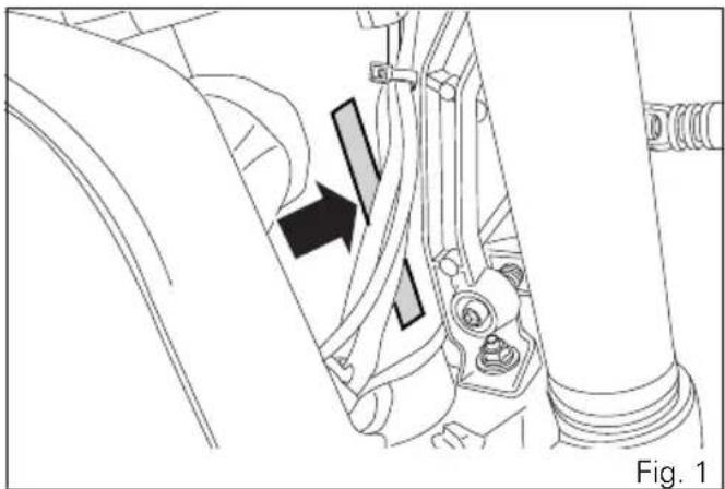
It is recommended to record the frame number (Fig. 1) of your motorcycle in the space below.
Frame number
natural_image
Mechanical assembly diagram showing a bracket with a black arrow indicating a specific component (no text or symbols present)Engine identification number

Note
These numbers identify the motorcycle model and should always be indicated when ordering spare parts.
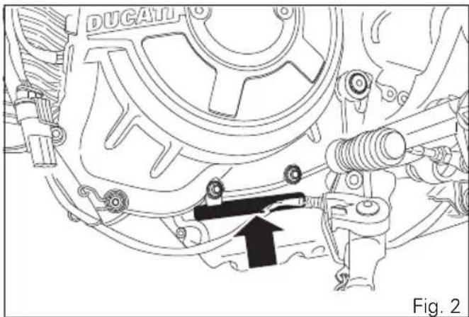
It is recommended to record the number of your motorcycle's engine (Fig. 2) in the space below.
Engine number
natural_image
Technical line drawing of a car engine assembly with no visible text or symbolsCustomisations
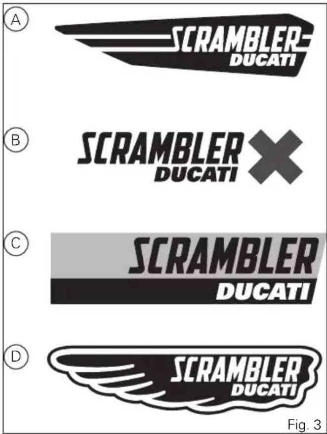
Each version is a customisation of the SCRAMBLER. The SCRAMBLER is available in four different customisations:
- ICON (A)
- URBAN ENDURO (B)
- FULL THROTTLE (C)
- CLASSIC (D)
Information herein refers to Scrambler ICON. Information on any other customisation (URBAN ENDURO, FULL THROTTLE, CLASSIC) is indicated only when different from the Scrambler ICON.
ICON
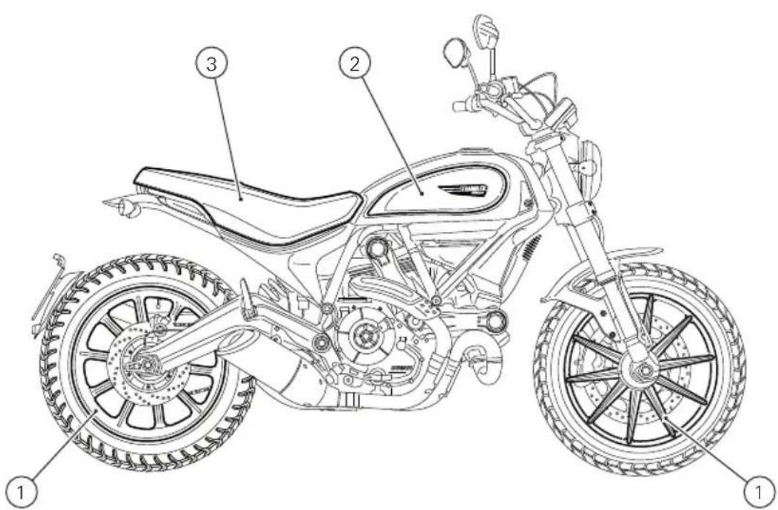
Fig. 4
ICON
1) Ten-spoke, light-alloy rims
2) Dedicated sticker with logo
3) Dedicated seat
URBAN ENDURO
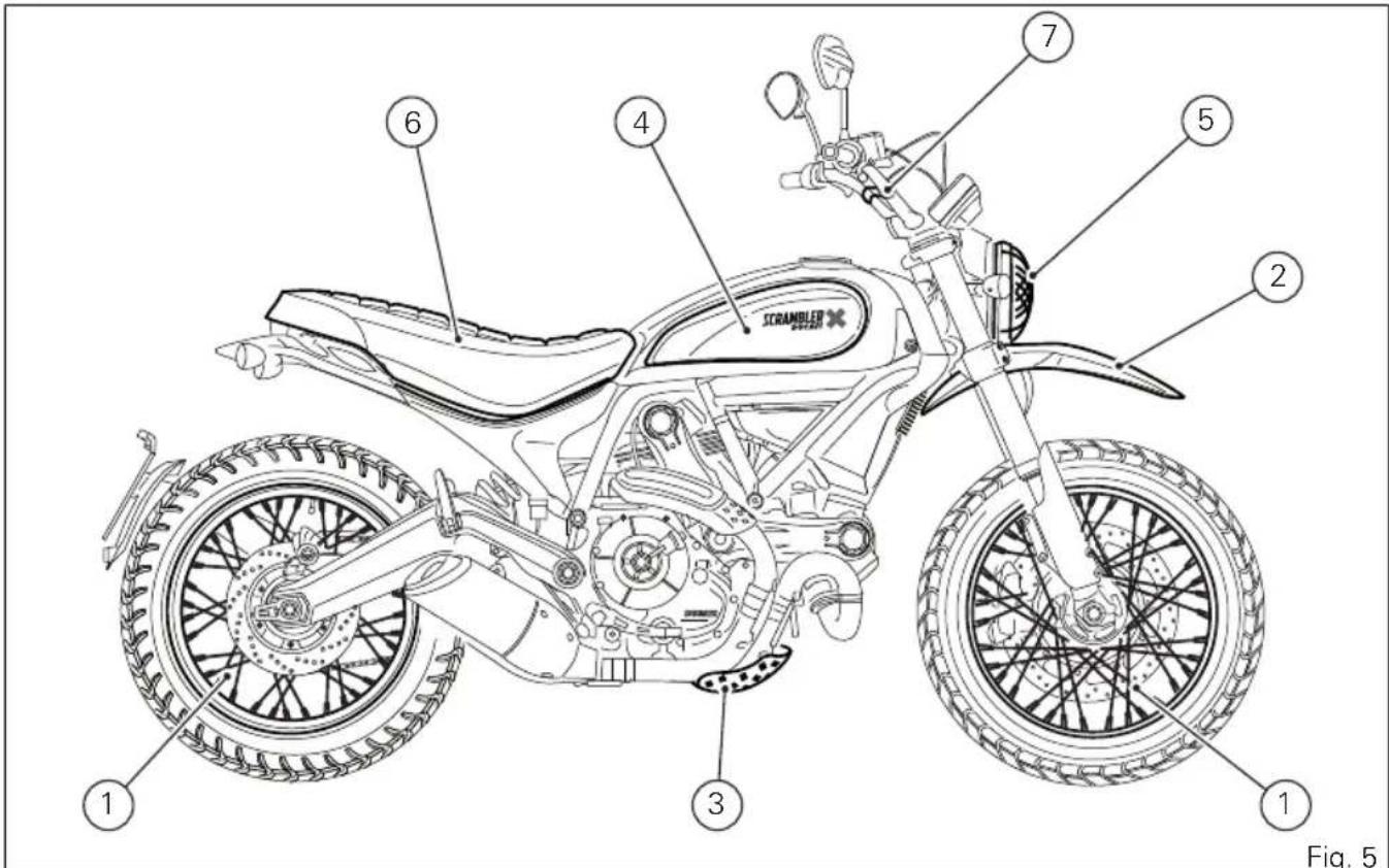
URBAN ENDURO
1) Spoked wheels
2) Raised front mudguard
3) Sump guard
4) Dedicated sticker with logo
5) Headlight grille as standard
6) Dedicated seat
7) Handlebar crosspiece
8) Front fork guards
FULL THROTTLE
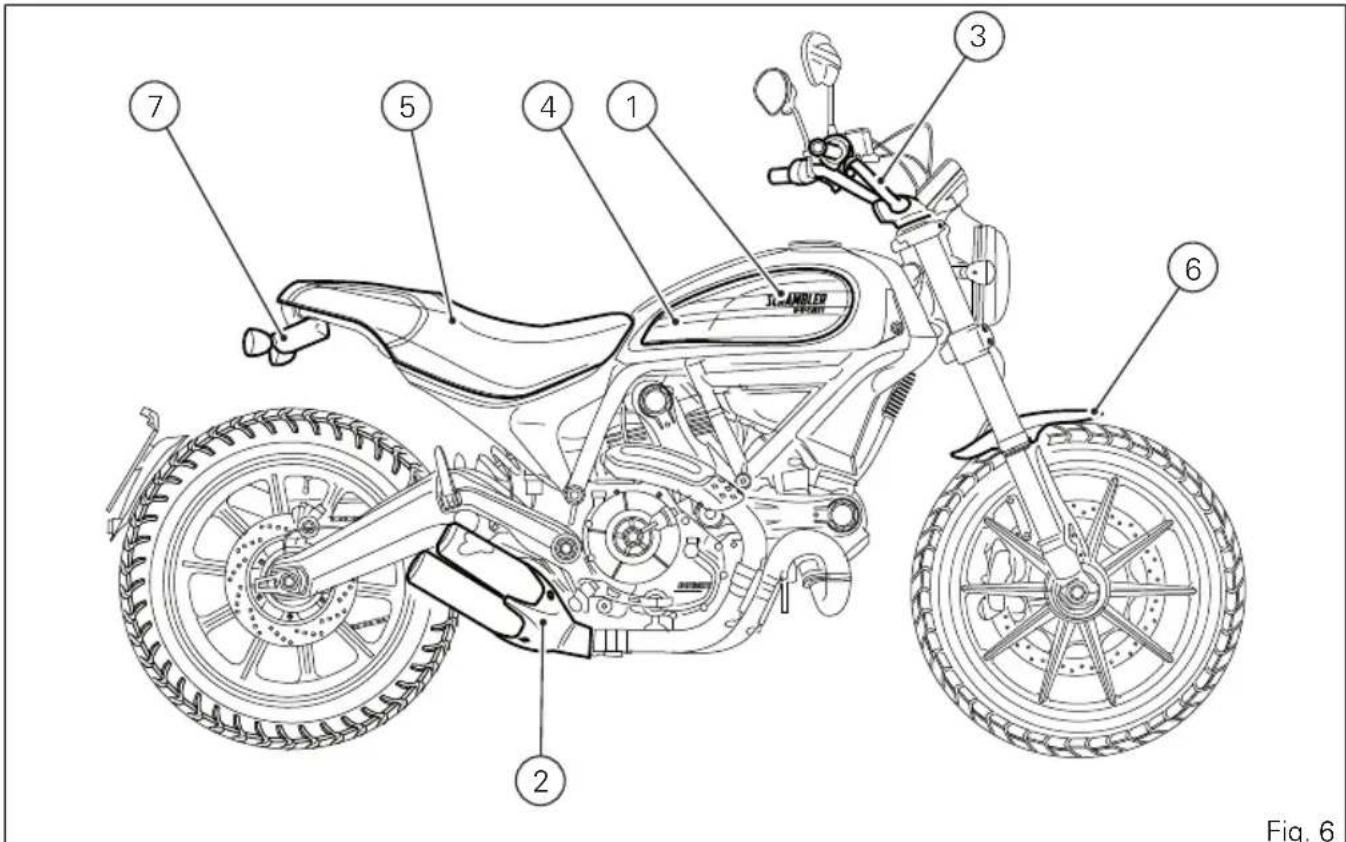
FULL THROTTLE
1) Dedicated sticker with logo
2) Tailpipe as standard (Termignoni)
3) Lowered handlebar
4) Black anodised side panels
5) Dedicated racing seat
6) Short front mudguard
7) Rear turn indicators with no splash guard
CLASSIC
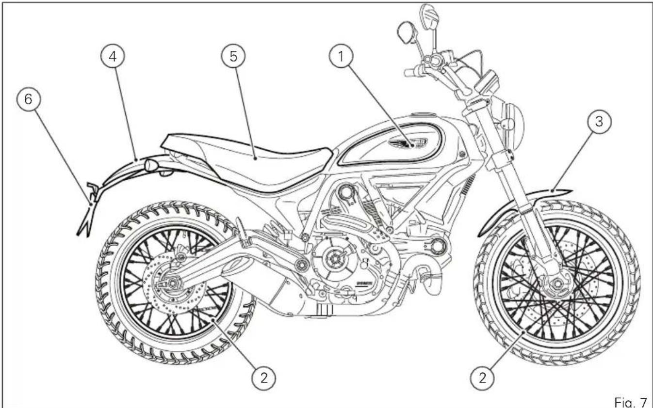
CLASSIC
1) Dedicated-thickness logo
2) Aluminium spoked wheels
3) Long, satin-finished aluminium front mudguard
4) Long, satin-finished rear mudguard
5) Dedicated seat
6) Raised number plate holder
Instrument panel (Dashboard)
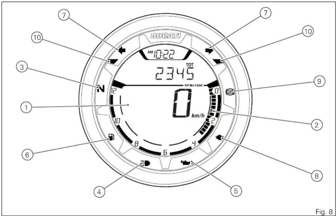
Instrument panel
1) LCD.
2) REV COUNTER (rpm).
It indicates engine rpm value.
3) NEUTRAL LIGHT N (GREEN).
Comes on when in neutral position.
4) HIGH BEAM LIGHT ☑ (BLUE).
It turns on to indicate that the high beam lights are on and when the flasher is activated.
5) ENGINE OIL PRESSURE LIGHT 📋 (RED).
Comes on when engine oil pressure is too low. It must turn on at "KEY-ON", but must turn OFF a few seconds after the engine has started. It may shortly come on when the engine is hot, however, it should go out as the engine revs up.

Important
If the ENGINE OIL light stays ON, stop the
engine or it may suffer severe damage.
6) FUEL WARNING LIGHT (AMBER YELLOW). Comes on when fuel is low and there are about 4 litres of fuel left in the tank.
7) TURN INDICATOR LIGHTS (GREEN).
A warning light turns on and blinks when the relevant turn indicator is active; when the warning lights blink at the same time, the HAZARD function is active.
8) "ENGINE/VEHICLE DIAGNOSIS - EOBD" LIGHT (AMBER YELLOW).
It turns on in the case of "engine" and/or "vehicle" errors and in some cases will lock the engine.
9) ABS LIGHTS (AMBER YELLOW).
This turns on to indicate that ABS is disabled or not functioning.
| Engine OFF / speed below 5 Km/h | ||
| Light OFF Light flashing | ng Light steady on | |
| - ABS disabled with the menu function "ABS" | ABS enabled, but not functioning yet | |
| Engine on / speed below 5 Km/h | ||
| Light OFF Light flashing | ng Light steady on | |
| - ABS disabled with the menu function "ABS" | ABS enabled, but not functioning yet | |
| Engine on / speed above 5 km/h | ||
| Light OFF Light flashing | ng Light steady on | |
| ABS enabled and functioning ABS | disabled with the menu function "ABS" | ABS disabled and not functioning due to a problem |
| Over rev | |
| No intervention Light OFF | |
| First threshold (N RPM before the limiter kicks in) | Light steady ON |
| Limiter Light ON flashing | |

Note
Each calibration of the Engine Control Unit may
have a different setting for the thresholds that precede the rev limiter and the rev limiter itself.
| Immobilizer | |
| Key-ON status Light OFF | |
| Key-OFF status Light ON flashing | |
| Key-OFF status for over 12 hours | Light OFF |
Acronyms and abbreviations used in the
Manual
ABS
Antilock Braking System
CAN
Controller Area Network
DDA
DUCATI Data Acquisition
DSB
Dashboard
ECU
Engine Control Unit
Technological Dictionary Anti-lock Braking System (ABS) 9M
ABS 9M system is a two-channel latest-generation system that actuates combined braking with anti lift-up function for the rear wheel so as to guarantee not only a reduced stopping distance, but also a higher stability under braking.
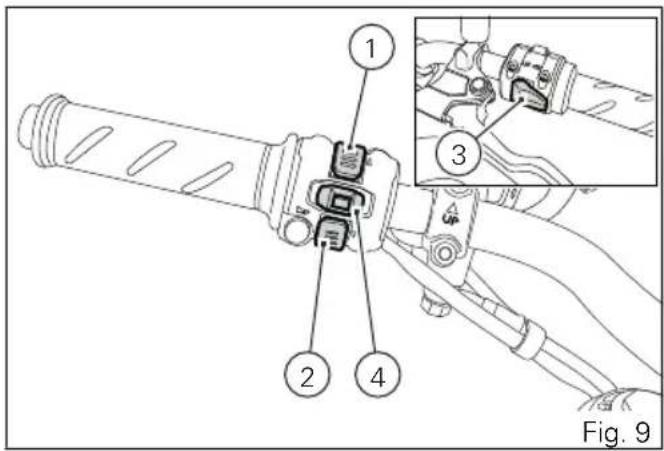
Function push-buttons
1) UP CONTROL SWITCH "▲"
Button used to display and set instrument panel parameters with the position "▲".
2) DOWN CONTROL SWITCH "▼"
Button used to display and set instrument panel parameters with the position "▼".
This button is the high-beam flasher.
4) TURN INDICATORS CANCEL BUTTON
The turn indicators cancel button may also be used for the CONFIRM MENU function, for selecting the riding mode. Push this button for 3 seconds to the left side to activate the "Hazard" function (all 4 turn indicators).
Parameter setting/displaying
Upon key-on, the instrument panel:
- turns on the display backlighting;
- activates the rev counter which increases from 0 to 12000 and decreases back to 0;
- activates the vehicle speed digits and shows a counting from 0 to 300 and then back to 0;
- turns on the warning lights from right to left.
At the end of the check, the instrument panel displays the main screen ("standard screen") showing the available functions and turns on the warning lights, if necessary.
During this first check stage, if the motorcycle speed exceeds 20 km/h (actual speed), the instrument panel will stop:
- the display check routine and display the standard screen containing updated information;
- the warning light check routine and leave ON only the warning lights that are actually active at the moment.
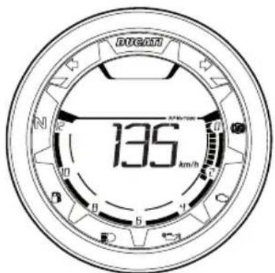
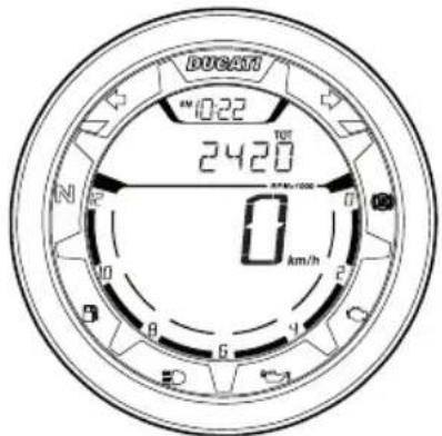
Fig. 10
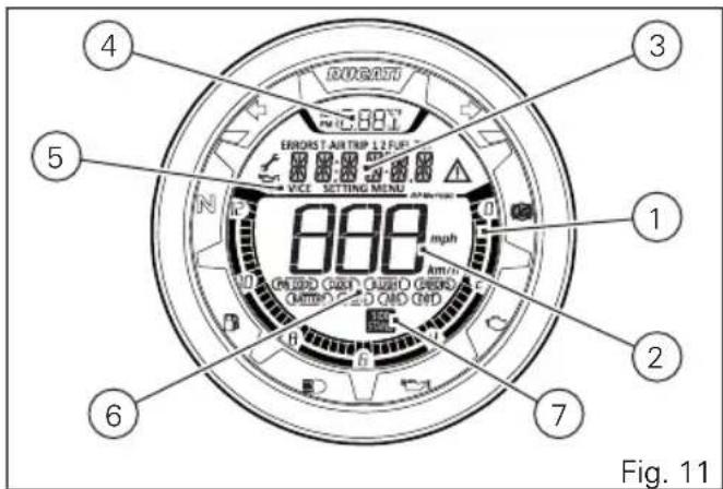
Data displayed on the main screen are as follows:
1) Engine speed.
2) Motorcycle speed.
3) MENU 1 (Odometer, Trip 1, Trip 2, Trip Fuel, Air temperature, Error warning - only if active).
4) Clock.
5) SERVICE indication (only if active).
6) Setting menu.
7) Side stand status.
From the main screen, press button (2) on LH switch to view Menu 1 information.
- Odometer (TOT);
- TRIP 1;
- TRIP 2;
- TRIP FUEL (when function is active);
-T-AIR.
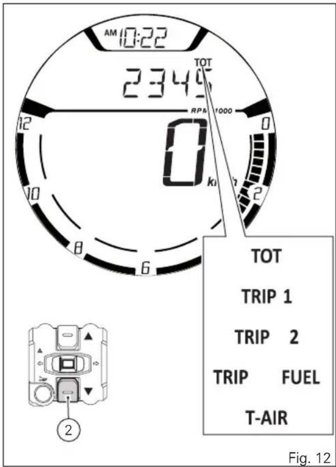
The instrument panel stores Menu 1 settings in use upon KEY-OFF. On the following KEY-ON, previously stored Menu 1 pages are displayed.
In case of sudden and unexpected power OFF, the instrument panel displays the default settings upon the following KEY-ON:
- Menu 1 default page = Odometer (TOT).
Upon KEY-ON, for every display layout, instrument panel shows for 10 seconds in Menu 1 the "Odometer" page and then shows the page saved upon previous KEY-OFF.
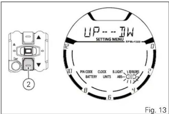
Hold the button (2) for 3 seconds, when actual motorcycle speed is <= (lower than or equal to) 20 km/h, to enter the Setting Menu, where you can set any function.

Important
You can enter the SETTING MENU only if vehicle actual speed is <= (lower than or equal to) 20 km/h. Within the SETTING MENU, if vehicle actual speed exceeds 20 km/h, the instrument panel automatically quits the menu and shows the standard screen.
Main functions
The functions displayed in the Standard screen are the following:
Main information
- Motorcycle speed
- Engine rpm indication (RPM)
- Menu 1 displays the following functions:
- Odometer (TOT)
- Trip meter 1 (TRIP 1)
- Trip meter 2 (TRIP 2)
- Partial fuel reserve counter (TRIP FUEL)
- Ambient air temperature (AIR)
- Clock
Additional information
- Service indication (SERVICE)
- ERROR indication
The functions within the Setting Menu that can be modified by the user are the following:
- PIN CODE (activation and modification of PIN CODE);
CLOCK (clock settings);
LIGHT (backlighting settings);
BATTERY (battery voltage indication);
UNITS (units of measurement settings);
ABS (ABS control unit enabling/disabling);
EXIT (to quit the Setting Menu)
Motorcycle speed
This function allows displaying the vehicle speed (km/h or mph according to the specific application).
The instrument panel receives information about the actual motorcycle speed (calculated in km/h) and displays the value increased by 5% and converted in the set unit of measurement (km/h or mph).
The max. displayed speed is 299 km/h (186 mph).
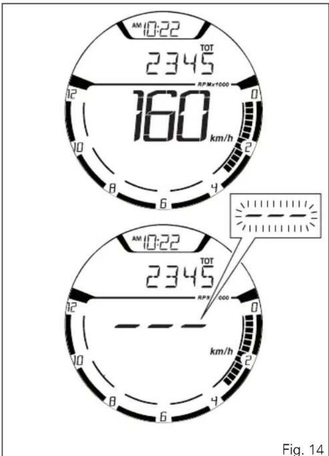
A string of dashes "--" is displayed with the set unit of measurement if:
- speed is higher than 299 km/h or 186 mph or if instrument panel is not receiving the speed value ("-- - " steady ON);
- the rear speed sensor is in fault (flashing "--").
Engine rpm indication (RPM)
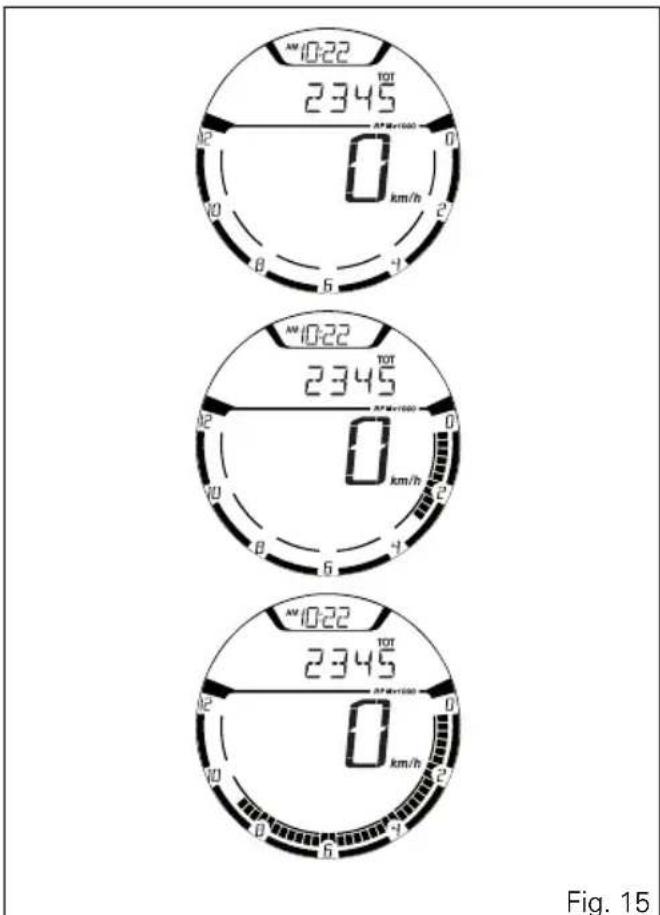
This function allows displaying engine rpm. Instrument panel receives rpm value and displays it. The information is displayed by the bargraph filling from the right to the left according to the engine rpm.
gauge
| Measurement | Value | |-------------|-------| | Current (MW 10:22) | 2345 | | Angular Scale (0 km/h) | 0 | | Current (MW 10:22) | 2345 | | Angular Scale (0 km/h) | 0 | | Current (MW 10:22) | 2345 | | Angular Scale (0 km/h) | 0 | | Current (MW 10:22) | 2345 | | Angular Scale (0 km/h) | 0 | | Current (MW 10:23) | 2345 | | Angular Scale (0 km/h) | 0 | | Current (MW 10:23) | 2345 | | Angular Scale (0 km/h) | 0 | | Current (MW 10:23) | 2345 | | Angular Scale (0 km/h) | 0 | | Current (MW 10:23) | 2345 | | Angle (°) | 0 | | Angle (°) | 6 | | Angle (°) | 9 | | Angle (°) | 12 | | Angle (°) | 15 | | Angle (°) | 18 | | Angle (°) | 21 | | Angle (°) | 24 | | Angle (°) | 27 | | Angle (°) | 30 | | Angle (°) | 33 | | Angle (°) | 36 | | Angle (°) | 39 | | Angle (°) | 42 | | Angle (°) | 45 | | Angle (°) | 48 | | Angle (°) | 51 | | Angle (°) | 54 | | Angle (°) | 57 | | Angle (°) | 60 | | Angle (°) | 63 | | Angle (°) | 66 | | Angle (°) | 69 | | Angle (°) | 72 | | Angle (°) | 75 | | Angle (°) | 78 | | Angle (°) | 81 | | Angle (°) | 84 | | Angle (°) | 87 | | Angle (°) | 90 | | Angle (°) | 93 | | Angle (°) | 96 | | Angle (°) | 99 | | Angle (°) | 102 | | Angle (°) | 105 | | Angle (°) | 108 | | Angle (°) | 111 | | Angle (°) | 114 | | Angle (°) | 117 | | Angle (°) | 120 | | Angle (°) | 123 | | Angle (°) | 126 | | Angle (°) | 129 | | Angle (°) | 132 | | Angle (°) | 135 | | Angle (°) | 138 | | Angle (°) | 141 | | Angle (°) | 144 | | Angle (°) | 147 | | Angle (°) | 150 | | Angle (°) | 153 | | Angle (°) | 156 | | Angle (°) | 159 | | Angle (°) | 162 | | Angle (°) | 165 | | Angle (°) | 168 | | Angle (°) | 171 | | Angle (°) | 174 | | Angle (°) | 177 | | Angle (°) | 180 | | Angle (°) | 183 | | Angle (°) | 186 | | Angle (°) | 189 | | Angle (°) | 192 | | Angle (°) | 195 | | Angle (°) | 198 | | Angle (°) | 201 | | Angle (°) | 204 | | Angle (°) | 207 | | Angle (°) | 210 | | Angle (°) | 213 | | Angle (°) | 216 | | Angle (°) | 219 | | Angle (°) | 222 | | Angle (°) | 225 | | Angle (°) | 228 | | Angle (°) | 231 | | Angle (°) | 234 | | Angle (°) | 237 | | Angle (°) | 240 | | Angle (°) | 243 | | Angle (°) | 246 | | Angle (°) | 249 | | Angle (°) | 252 | | Angle (°) | 255 | | Angle (°) | 258 | | Angle (°) | 261 | | Angle (°) | 264 | | Angle (°) | 267 | | Angle (°) | 270 | | Angle (°) | 273 | | Angle (°) | 276 | | Angle (°) | 279 | | Angle (°) | 282 | | Angle (°) | 285 | | Angle (°) | 288 | | Angle (°) | 291 | | Angle (°) | 294 | | Angle (°) | 297 | | Angle (°) | 300 | | Angle (°) | 303 | | Angle (°) | 306 | | Angle (°) | 309 | | Angle (°) | 312 | | Angle (°) | 315 | | Angle (°) | 318 | | Angle (°) | 321 | | Angle (°) | 324 | | Angle (°) | 327 | | Angle (°) | 330 | | Angle (°) | 333 | | Angle (°) | 336 | | Angle (°) | 339 | | Angle (°) | 342 | | Angle (°) | 345 | | Angle (°) | 348 | | Angle (°) | 351 | | Angle (°) | 354 | | Angle (°) | 357 | | Angle (°) | 360 | | Angle (°) | 363 | | Angle (°) | 366 | | Angle (°) | 369 | | Angle (°) | 372 | | Angle (°) | 375 | | Angle (°) | 378 | | Angle (°) | 381 | | Angle (°) | 384 | | Angle (°) | 387 | | Angle (°) | 390 | | Angle (°) | 393 | | Angle (°) | 396 | | Angle (°) | 399 | | Angle (°) | 402 | | Angle (°) | 405 | | Angle (°) | 408 | | Angle (°) | 411 | | Angle (°) | 414 | | Angle (°) | 417 | | Angle (°) | 420 | | Angle (°) | 423 | | Angle (°) | 426 | | Angle (°) | 429 | | Angle (°) | 432 | | Angle (°) | 435 | | Angle (°) | 438 | | Angle (°) | 441 | | Angle (°) | 444 | | Angle (°) | 447 | | Angle (°) | 450 | | Angle (°) | 453 | | Angle (°) | 456 | | Angle (°) | 459 | | Angle (°) | 462 | | Angle (°) | 465 | | Angle (°) | 468 | | Angle (°) | 471 | | Angle (°) | 474 | | Angle (°) | 477 | | Angle (°) | 480 | | Angle (°) | 483 | | Angle (°) | 486 | | Angle (°) | 489 | | Angle (°) | 492 | | Angle (°) | 495 | | Angle (°) | 498 | | Angle (°) | 501 | | Angle (°) | 504 | | Angle (°) | - | Fig.15The thresholds before the rpm limiter are:
1^st threshold 8900 rpm (A).
When the rev limiter value (B) is reached, the warning lights start flashing.
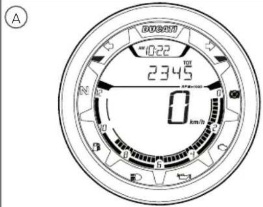
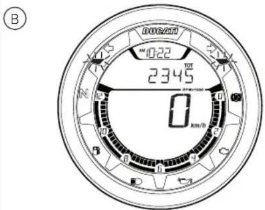
Fig. 16
Menu 1 functions
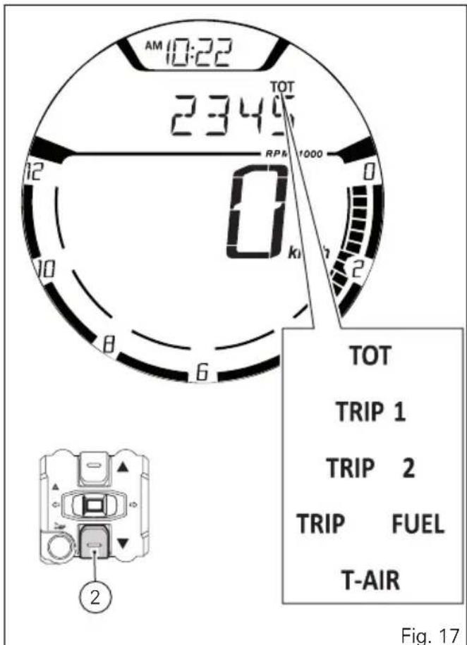
MENU 1 functions are:
- Odometer (TOT);
- Trip meter 1 (TRIP 1);
- Trip meter 2 (TRIP 2);
- Partial fuel reserve counter (TRIP FUEL);
- Ambient air temperature (T-AIR).
By pressing button (2) it is possible to view the functions of MENU 1.
Odometer (TOT)
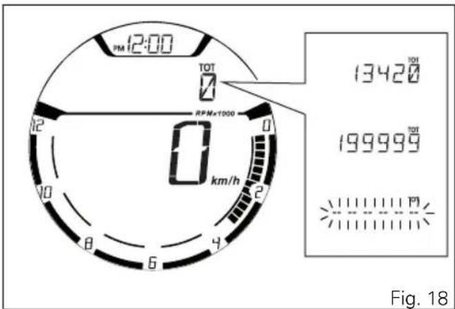
The odometer counts and displays the total distance covered by the motorcycle with the set unit of measurement (km or mi).
The odometer number (in km or miles) is displayed with the message TOT and the indication of the unit of measurement. When the maximum value is reached (199999 km or 199999 mi) the instrument panel will permanently display said value.
The odometer value is saved permanently and cannot be reset under any circumstances.
The reading is not lost in case of a power OFF (Battery OFF).

Note
Upon Key-ON, the instrument panel always shows the Odometer indication for 10 seconds, then shows the user's settings page.

Note
If a string of flashing dashes "----" is displayed within odometer function, please contact a Ducati Dealer or Authorised Service Centre.
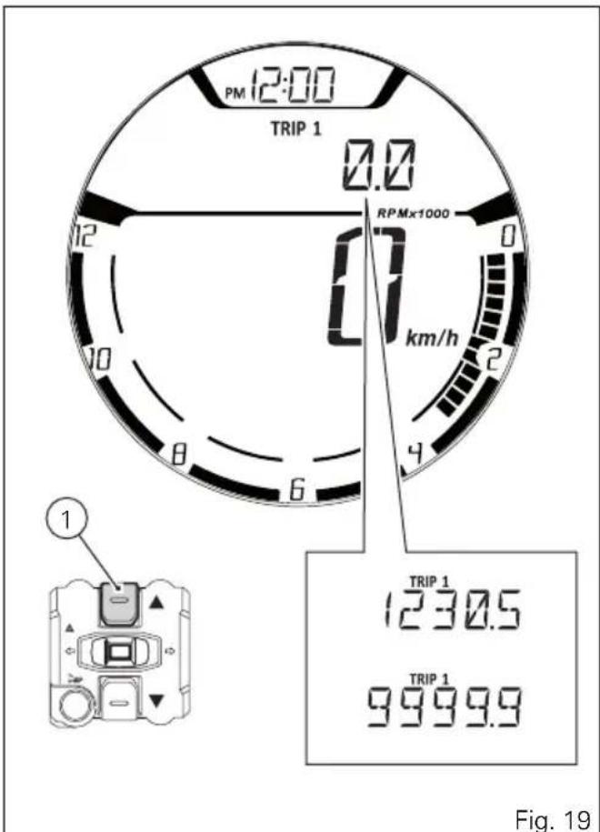
Trip meter 1 (TRIP 1)
The trip meter counts and displays the partial distance covered by the motorcycle with the set unit of measurement (km or mi).
When the reading exceeds the maximum value of 9999.9 km or 9999.9 mi, distance travelled is reset and the meter automatically starts counting from 0 again.
While the trip meter is displayed, press button (1) for 3 seconds to reset TRIP 1.
The TRIP 1 counter is automatically reset in case the system unit of measurement is changed manually or if the power supply is interrupted (faulty battery): the counter will then start back from zero, considering the new units of measurement.
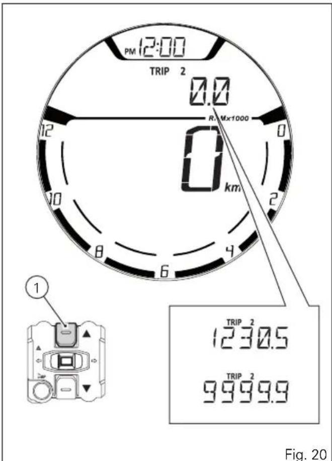
Trip meter 2 (TRIP 2)
The trip meter counts and displays the partial distance covered by the motorcycle with the set unit of measurement (km or mi).
When the reading exceeds the maximum value of 9999.9 km or 9999.9 mi, distance travelled is reset and the meter automatically starts counting from 0 again.
While the trip meter is displayed, press button (1) for 3 seconds to reset TRIP 2.
The TRIP 2 counter is automatically reset in case the system unit of measurement is changed manually or if the power supply is interrupted (faulty battery): the counter will then start back from zero, considering the new units of measurement.
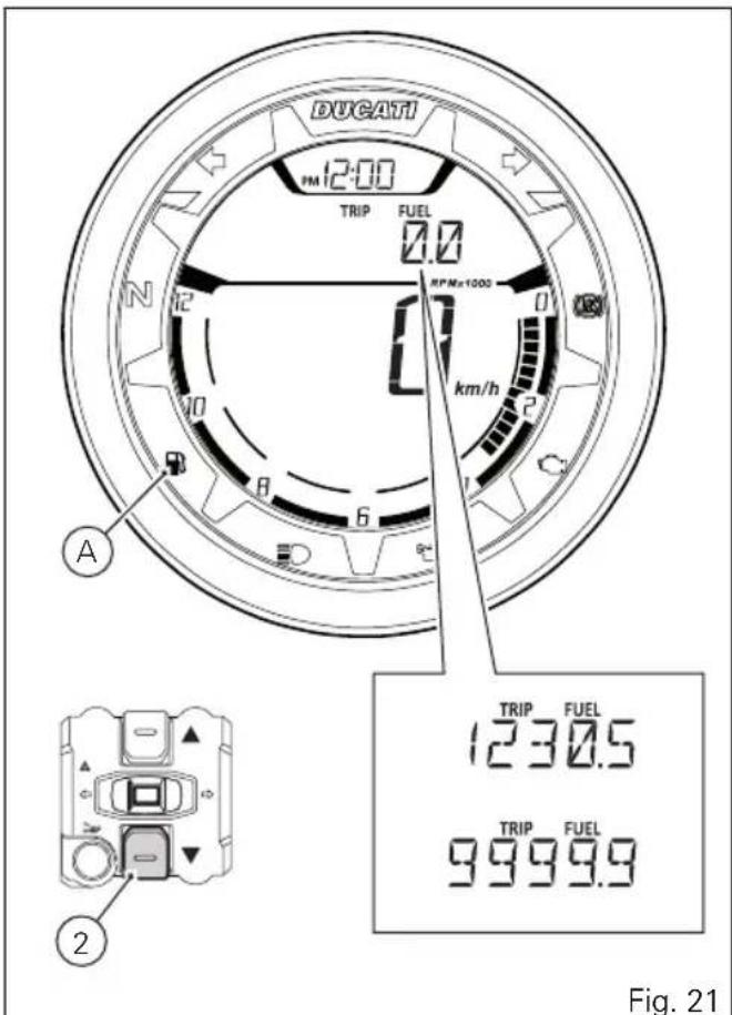
Partial fuel reserve counter (TRIP FUEL)
The fuel trip meter counts and displays the distance covered by the motorcycle on reserve (since the low fuel light turns on) with the set unit of measurement (km or mi).
When the Low Fuel Light (A) turns on, the display automatically shows the TRIP FUEL function, regardless of the currently displayed function; then, it is possible to toggle through the other Menu functions using button (2).
Trip fuel reading remains stored even after Key-Off until the motorcycle is refuelled. Count is interrupted automatically as soon as fuel is topped up to above minimum level.
When the reading exceeds the maximum value of 9999.9 km or 9999.9 mi, distance travelled is reset and the meter automatically starts counting from 0 again.

Note
If the system measurement units are changed at any moment, or if there is an interruption in the power supply (Battery Off), the distance travelled is reset and the count starts from zero (considering the newly set unit of measurement).
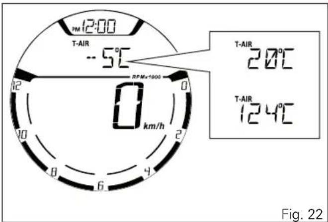
Ambient air temperature (AIR)
The instrument panel displays the ambient temperature in the set unit of measurement (°C or °F), followed by the set unit of measurement and the message T-AIR. The temperature value is displayed when ranging from -39 °C to +124 °C (or -38 °F ÷ +255 °F). For any different temperature (below -39 °C (-38 °F) or above +124 °C (+255 °F)) a string of three dashes "---" is steadily displayed, followed by the unit of measurement.
If the air temperature sensor is in fault, the instrument panel will show three flashing dashes "--" as air temperature value, followed by the unit of measurement and the EOBD light will turn on.

Note
When the motorcycle is stopped, the engine
heat could influence the displayed temperature.
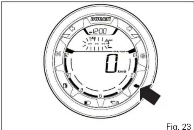
Errors
The instrument panel manages error warnings in order to allow the rider to identify any abnormal motorcycle behaviour in real time.
Upon Key-ON - if there are active errors - or during normal operation of the vehicle - whenever an error is triggered - the instrument panel turns the EOBD light and Warning symbol ON and indicates the triggered error.
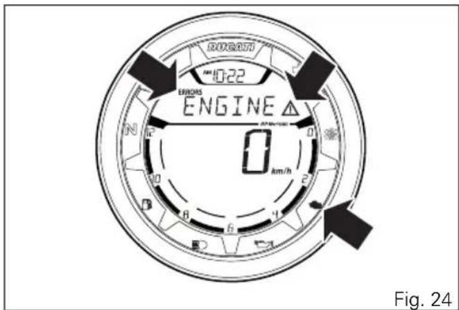
Error warnings
Any active errors are displayed in the MENU. MENU functions can still be viewed by pressing button (2).
If several errors are active, the corresponding indications will be displayed one after the other, each remaining on display for 3 seconds.
When an error is triggered the EOBD light turns on as well.

Warning
When one or more errors are displayed, always contact a Ducati Dealer or authorised Service Centre.
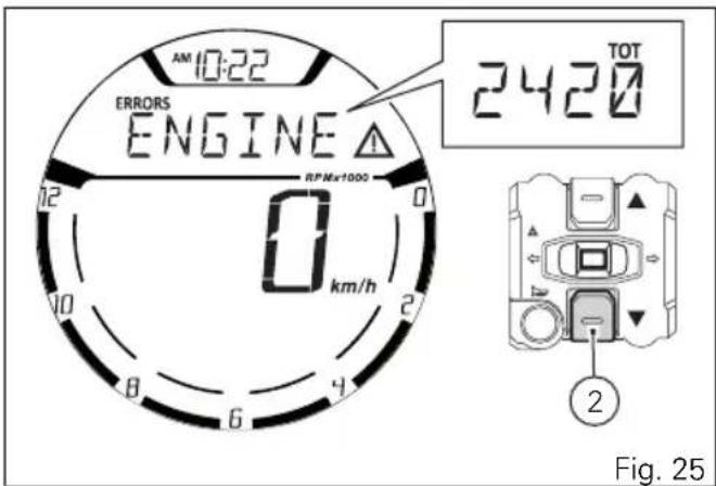
Displayed errors description
| Displayed error Description | |
| ENGINE Throttle position sensor malfunction | |
| IMMO Generic error | |
| DSB DSB control unit faulty | communication / operation |
| SD.STND Side stand sensor | not working |
Error icons table
WARNING LIGHT / ERROR MESSAGE ERROR
| ENGINE Engine control unit | |
| AIR - T. Air temperature sensor | |
| BATT. Battery voltage | |
| SPEED Speed sensor | |
| FUEL Low fuel sensor | |
| ABS ABS control unit | |
| CAN Can Bus OFF | |
| IMMO Immobilizer antenna | |
| DSB Instrument panel control unit |
WARNING LIGHT / ERROR MESSAGE ERROR

SD.STND Side stand sensor
Clock
The instrument panel receives information about the time to be displayed.
The instrument panel shows the time in the following format:
- hh (hours) : mm (minutes);
- with the message AM (for values ranging between 0:00 and 11:59), or PM (for values ranging between 12:00 and 12:59 and between 1:00 and 11:59).
In case of power supply interruption (faulty battery), the clock is reset and starts automatically from "0:00".
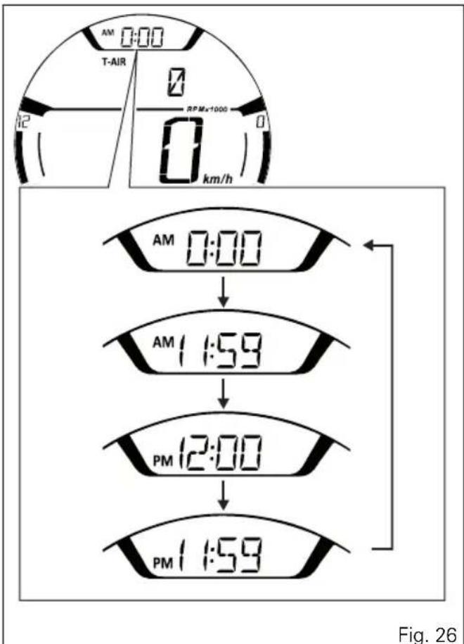
flowchart
graph TD
    A["AM 0:00"] --> B["AM 1:59"]
    B --> C["PM 12:00"]
    C --> D["PM 1:59"]
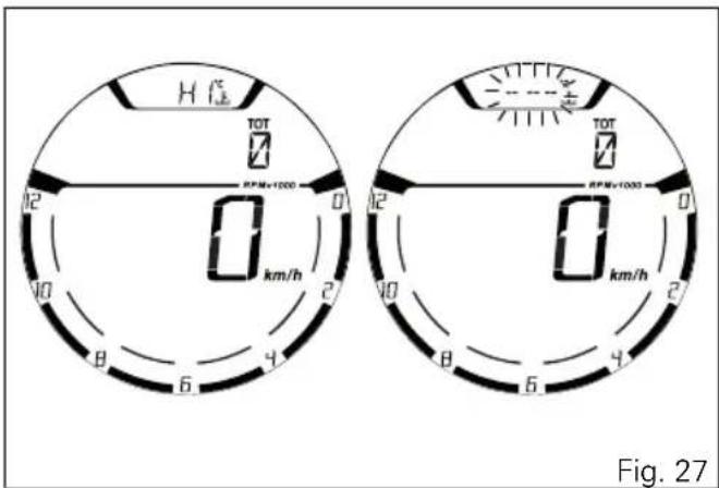
High engine temperature
This Function shows an alert indicating that engine temperature reached high values: warning triggers when engine temperature exceeds 200°C.
- flashing HI message;
- steady temperature icon and set unit of measurement (°C or °F).

Note
When this warning is triggered, the instrument panel will not display the clock until value gets equal to or below 200°C.

Note
If engine temperature sensor is in fault or if instrument panel is not receiving engine temperature information, a string of flashing dashes "---" is displayed.
Service indication (SERVICE)
This indication shows the user that the motorcycle is due for service and must be taken to a Ducati Authorised Service Centre.
The service warning indication can be reset only by the Authorised Ducati Service Centre during servicing.
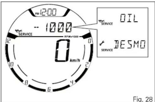
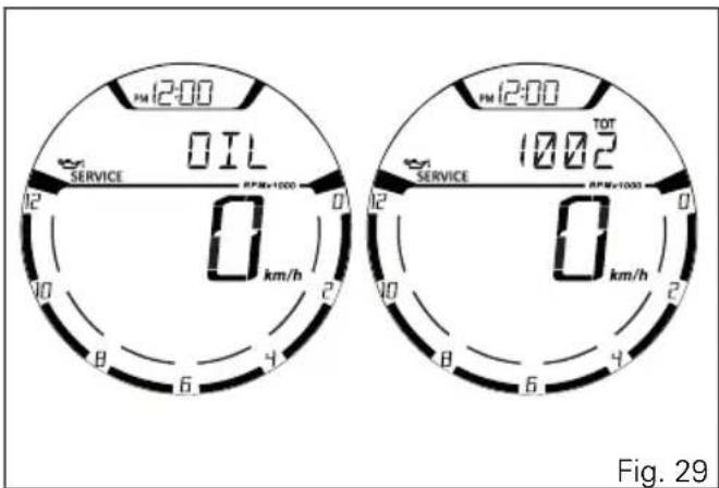
OIL SERVICE zero warning
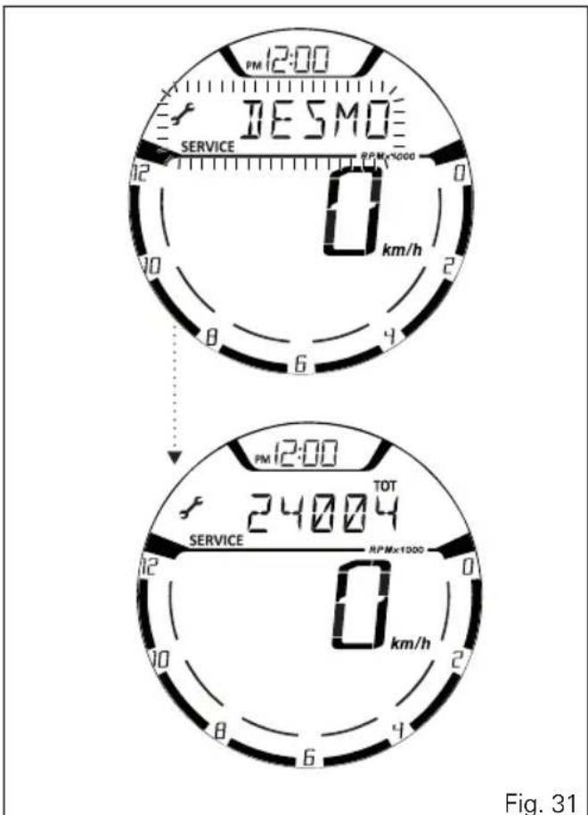
The first maintenance indication is OIL SERVICE zero, enabled for 5 seconds upon each key-on when the odometer counter reaches the first 1,000 km (600 mi).
The indication includes displaying for 5 seconds the flashing message "SERVICE", the Oil symbol and the message "OIL" upon each Key-ON; after 5 seconds, both the message "SERVICE" and the Oil symbol become steady until Key-OFF or until an Authorised Ducati Service Centre performs a reset.
DESMO SERVICE countdown indication After OIL SERVICE zero indication first reset (at 1,000 km - 600 mi), the instrument panel activates the countdown of the kilometres (or miles) left before the following service operation: DESMO SERVICE. The kilometre count indication is shown upon Key-ON for 2 seconds; when there are 1,000 km (600 miles) left before the next service operation, the indication turns on upon every Key-ON for 5 seconds. In other words, upon key-on the message "SERVICE" and the Desmo symbol are displayed together with the indication of the kilometres left before the following service operation.
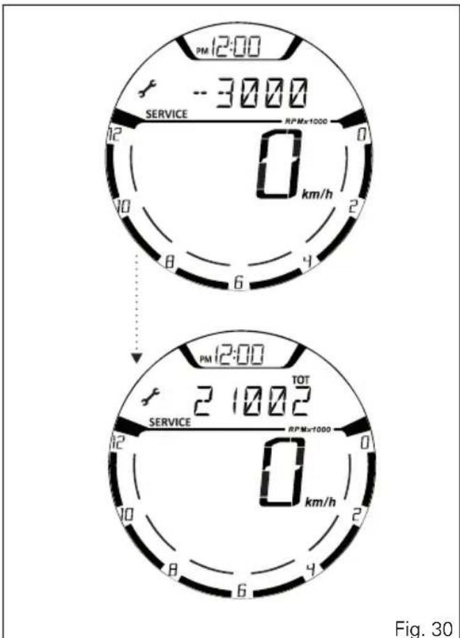
DESMO SERVICE indication
When the service threshold is reached, the warning for the type of service required is triggered: DESMO SERVICE.
The indication includes displaying for 5 seconds the flashing message "SERVICE", the Desmo symbol and the message "DESMO" upon each Key-ON; after 5 seconds, both the message "SERVICE" and the Desmo symbol become steady until Key-OFF or until an Authorised Ducati Service Centre performs a reset.
Setting menu
This menu allows enabling, disabling and setting some motorcycle functions.
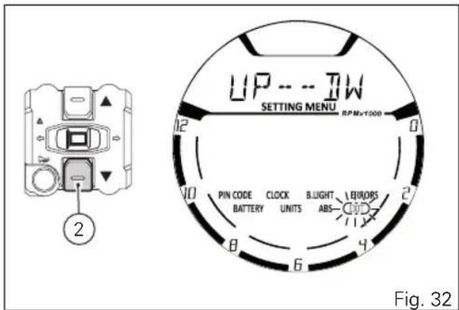
To enter the SETTING MENU it is necessary to hold button (3) for 2 seconds, with Key-ON and motorcycle actual speed ≤ (lower than or equal to) 20 km/h: within this menu, it is no longer possible to view any other function.
The SETTING MENU displays the following functions:
- PIN CODE (activation and modification of PIN CODE);
- CLOCK (clock settings);
- B.LIGHT (backlighting settings);
- BATTERY (battery voltage indication);
- UNITS (units of measurement settings);
- ABS (ABS control unit enabling/disabling);
- EXIT (to quit the Setting Menu).
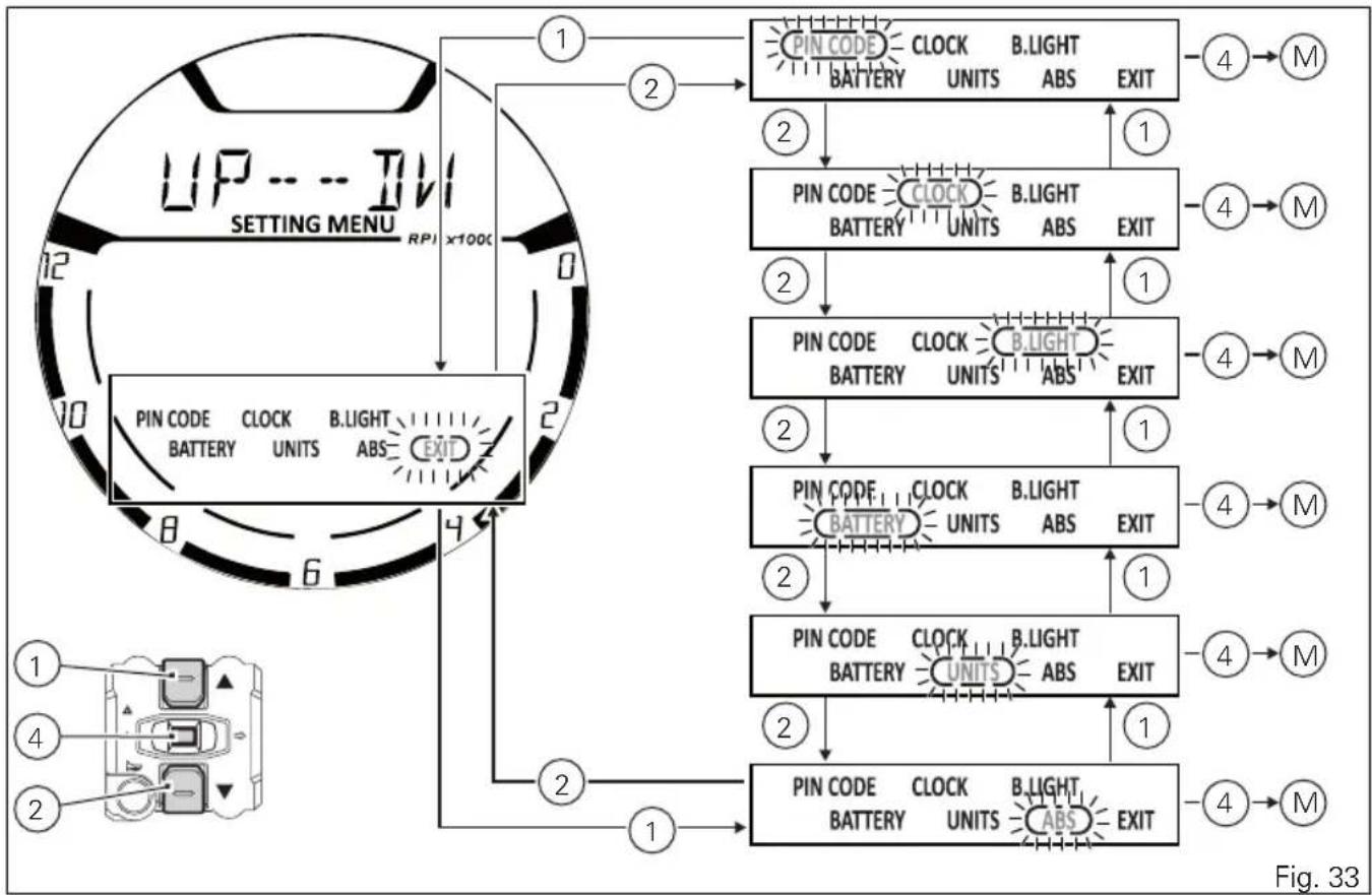
For safety reasons, the setting menu can be accessed only when vehicle speed is below or equal to 20 Km/h; if this menu is accessed and vehicle speed is above 20 Km/h, the instrument panel will automatically quit it and shift back to main screen.
Press buttons (1) and (2) to highlight the customisable parameters one by one: in particular, use button (2) to highlight the following item and button (1) to highlight the previous item.
After highlighting the required parameter, press button (4) to open the corresponding MENU (M) page.
If function is not available or temporarily disabled, the MENU page can not be opened.
To quit the SETTING MENU you shall highlight "EXIT" and press CONFIRM MENU button (4).
flowchart
graph TD
    A["UP...TIV<br>SETTING MENU RPI x100k"] --> B["1"]
    B --> C["2"]
    C --> D["3"]
    D --> E["4"]
    E --> F["M"]
    A --> G["2"]
    G --> H["3"]
    H --> I["4"]
    I --> J["M"]
    A --> K["2"]
    K --> L["3"]
    L --> M["4"]
    M --> N["M"]
    A --> O["2"]
    O --> P["3"]
    P --> Q["4"]
    Q --> R["M"]
    A --> S["2"]
    S --> T["3"]
    T --> U["4"]
    U --> V["M"]
    A --> W["2"]
    W --> X["3"]
    X --> Y["4"]
    Y --> Z["M"]
    A --> AA["2"]
    AA --> AB["3"]
    AB --> AC["4"]
    AC --> AD["M"]
ABS control uni enabling/disabling
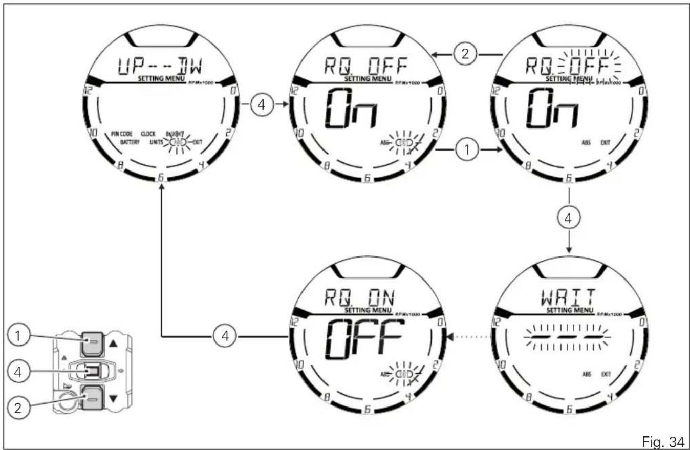
This function allows enabling or disabling the ABS system. Enter the SETTING MENU.
Select the parameter to be customised (ABS), by pressing button (1) or (2). Once the desired parameter is highlighted, press CONFIRM MENU button (4).
When entering the function, the currently set ABS status will be displayed:
On = enabled, Off = disabled.
Menu indicates the available alternative option (RQ): RQ OFF when current status is "On", RQ ON when current status is "Off".
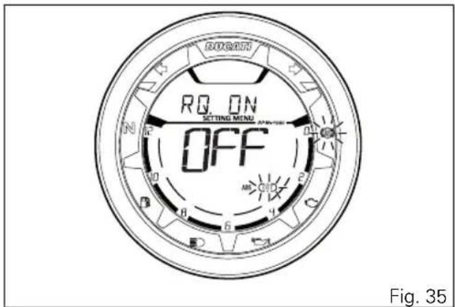
To quit the function without changing set status, select EXIT using button (2); when its box is flashing, press button (4).
To select a different status than the one set, press button (1); alternative option (RQ) starts flashing in the Menu.
Press button (4) for 3 seconds to confirm. WAIT is displayed in the Menu for approx. 5 seconds. New status will then become steady on and "EXIT" box will be flashing.
Press button (4) to quit the function.
flowchart
graph TD
    A["UP --- TW<br>SETTING MENU RPM+1000"] --> B["4"]
    B --> C["On"]
    C --> D["2"]
    D --> E["Setting MENU RPM+1000"]
    E --> F["1"]
    F --> G["On"]
    G --> H["4"]
    H --> I["WAIT<br>SETTING MENU RPM+1000"]
    I --> J["4"]
    J --> K["OFF"]
    K --> L["4"]
    L --> M["Pin CODE<br>BATTERY CLOCK UNITS SWITCH OUT"]
    M --> N["①"]
    N --> O["②"]
    O --> P["③"]
    P --> Q["④"]

Note
By setting "-" (Off), the ABS will be disabled and the relevant warning light will start flashing.

Important
When setting the ABS OFF, Ducati recommends paying particular attention to the braking and riding style.
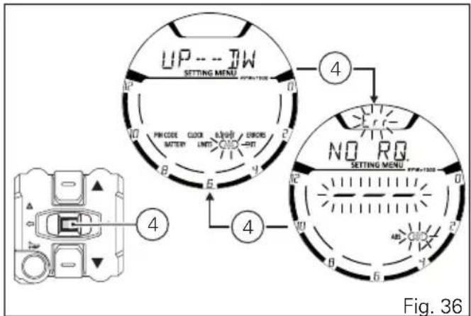
If the ABS is in fault, "Err" is displayed when entering the function and Menu will indicate "NO RQ", since no selection is actually possible. "EXIT" box is flashing. Press button (4) for 3 seconds to quit the function.
Battery voltage
This function allows you to check the motorcycle battery voltage. Enter the SETTING MENU. Select BATTERY option, by pressing button (1) or (2). Once function is highlighted, press CONFIRM MENU button (4). You open the BATTERY Menu.
The information will be displayed as follows:
- if battery voltage is between 11.8 V and 14.9 V the reading will be displayed steady;
- if battery voltage is between 0.0 and 11.7 Volt the reading will be displayed with "LOW" message flashing;
- if battery voltage is between 15.0 and 25.5 Volt the reading will be displayed with "HIGH" message flashing.
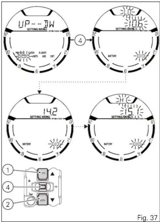
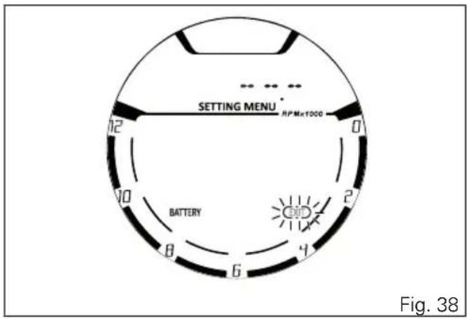
If the instrument panel is not receiving battery voltage value, a string of three dashes "---" is displayed. To quit the menu and go back to Setting Menu main page, select EXIT and press button (4).
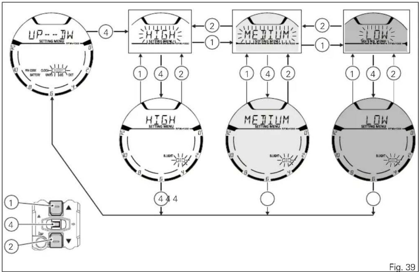
Instrument panel back-lighting setting (B.LIGHT)
This function allows adjusting the backlighting intensity.
To set the backlighting enter the SETTING MENU, use buttons (1) and (2) to select "B.LIGHT" and press button (4) to confirm.
When accessing the function, the active mode flashes whereas the MENU and EXIT messages will be steady on.
Use buttons (1) and (2) to select the desired brightness level (HIGH, MED, LOW) and press button (4) to confirm.
Select HIGH to set the display backlighting maximum brightness - recommended in conditions of strong ambient light.
Select MED to set the display backlighting medium brightness (70%) - recommended in conditions of medium/low ambient light.
Select LOW to set the display backlighting minimum brightness (50%) - recommended in conditions of low ambient light and/or during the night.
After confirming, the "EXIT" box will start flashing.
To exit the menu and go back to the previous page, select "EXIT" and press button (4).

Note
In the event of an interruption of the power supply from the Battery, when power is restored, at the next Key-On, the backlighting will always be set by default to maximum brightness.
flowchart
graph TD
    A["UP---TW<br>SETTING MENU APP/COOR"] -->|4| B["HIGH<br>SETTING MENU APP/COOR"]
    B -->|1| C["MEDIUM<br>SETTING MENU APP/COOR"]
    B -->|2| D["LOW<br>SETTING MENU APP/COOR"]
    C -->|1| E["MEDIUM<br>SETTING MENU APP/COOR"]
    C -->|2| F["LOW<br>SETTING MENU APP/COOR"]
    D -->|1| G["MEDIUM<br>SETTING MENU APP/COOR"]
    D -->|2| H["LOW<br>SETTING MENU APP/COOR"]
    I["IN CODE<br>BATTERY CLOCK UNITS TAGI OUT"] --> A
    J["IN CODE<br>PIN CODE CLOCK UNITS TAGI OUT"] --> A
    K["IN CODE<br>PIN CODE CLOCK UNITS TAGI OUT"] --> A
    L["IN CODE<br>PIN CODE CLOCK UNITS TAGI OUT"] --> M["4 4 4"]
    N["IN CODE<br>PIN CODE CLOCK UNITS TAGI OUT"] --> O["6 6 6"]
    P["IN CODE<br>PIN CODE CLOCK UNITS TAGI OUT"] --> Q["8 8 8"]
    R["IN CODE<br>PIN CODE CLOCK UNITS TAGI OUT"] --> S["10 10 10"]
    T["IN CODE<br>PIN CODE CLOCK UNITS TAGI OUT"] --> U["12 12 12"]
    V["IN CODE<br>PIN CODE CLOCK UNITS TAGI OUT"] --> W["14 14 14"]
    X["IN CODE<br>PIN CODE CLOCK UNITS TAGI OUT"] --> Y["16 16 16"]
    Z["IN CODE<br>PIN CODE CLOCK UNITS TAGI OUT"] --> AA["18 18 18"]
    AB["IN CODE<br>PIN CODE CLOCK UNITS TAGI OUT"] --> AC["20 20 20"]
    AD["IN CODE<br>PIN CODE CLOCK UNITS TAGI OUT"] --> AE["22 22 22"]
    AF["IN CODE<br>PIN CODE CLOCK UNITS TAGI OUT"] --> AG["24 24 24"]
    AH["IN CODE<br>PIN CODE CLOCK UNITS TAGI OUT"] --> AI["26 26 26"]
    AJ["IN CODE<br>PIN CODE CLOCK UNITS TAGI OUT"] --> AK["28 28 28"]
    AL["IN CODE<br>PIN CODE CLOCK UNITS TAGI OUT"] --> AM["30 30 30"]
    AN["IN CODE<br>PIN CODE CLOCK UNITS TAGI OUT"] --> AO["32 32 32"]
    AP["IN CODE<br>PIN CODE CLOCK UNITS TAGI OUT"] --> AQ["34 34 34"]
    AR["IN CODE<br>PIN CODE CLOCK UNITS TAGI OUT"] --> AS["36 36 36"]
    AT["IN CODE<br>PIN CODE CLOCK UNITS TAGI OUT"] --> AU["38 38 38"]
    AV["IN CODE<br>PIN CODE CLOCK UNITS TAGI OUT"] --> AW["40 40 40"]
    AX["IN CODE<br>PIN CODE CLOCK UNITS TAGI OUT"] --> AY["42 42 42"]
    AZ["IN CODE<br>PIN CODE CLOCK UNITS TAGI OUT"] --> BA["44 44 44"]
    BB["IN CODE<br>PIN CODE CLOCK UNITS TAGI OUT"] --> BC["46 46 46"]
    BD["IN CODE<br>PIN CODE CLOCK UNITS TAGI OUT"] --> BE["48 48 48"]
    BF["IN CODE<br>PIN CODE CLOCK UNITS TAGI OUT"] --> BG["50 50 50"]
    BH["IN CODE<br>PIN CODE CLOCK UNITS TAGI OUT"] --> BI["52 52 52"]
    BJ["IN CODE<br>PIN CODE CLOCK UNITS TAGI OUT"] --> BK["54 54 54"]
    BL["IN CODE<br>PIN CODE CLOCK UNITS TAGI OUT"] --> BM["56 56 56"]
    BN["IN CODE<br>PIN CODE CLOCK UNITS TAGI OUT"] --> BO["58 58 58"]
    BP["IN CODE<br>PIN CODE CLOCK UNITS TAGI OUT"] --> BQ["60 60 60"]
    BR["IN CODE<br>PIN CODE CLOCK UNITS TAGI OUT"] --> BS["62 62 62"]
    BT["IN CODE<br>PIN CODE CLOCK UNITS TAGI OUT"] --> BU["64 64 64"]
    BV["IN CODE<br>PIN CODE CLOCK UNITS TAGI OUT"] --> BW["66 66 66"]
    BX["IN CODE<br>PIN CODE CLOCK UNITS TAGI OUT"] --> BY["68 68 68"]
    BZ["IN CODE<br>PIN CODE CLOCK UNITS TAGI OUT"] --> BZM["69 69 69"]
    CA["IN CODE<br>PIN CODE CLOCK UNITS TAGI OUT"] --> CB["70 70 70"]
    CC["IN CODE<br>PIN CODE CLOCK UNITS TAGI OUT"] --> CD["72 72 72"]
    CE["IN CODE<br>PIN CODE CLOCK UNITS TAGI OUT"] --> CF["74 74 74"]
    CG["IN CODE<br>PIN CODE CLOCK UNITS TAGI OUT"] --> DH["76 76 76"]
    DI["IN CODE<br>PIN CODE CLOCK UNITS TAGI OUT"] --> DJ["78 78 78"]
    DK["IN CODE<br>PIN CODE CLOCK UNITS TAGI OUT"] --> DL["80 80 80"]
    DV["IN CODE<br>PIN CODE CLOCK UNITS TAGI OUT"] --> DW["82 82 82"]
    DX["IN CODE<br>PIN CODE CLOCK UNITS TAGI OUT"] --> DXM["84 84 84"]
    DXM --> DXN["86 86 86"]
    DXN --> DXO["88 88 88"]
    DXO --> DXP["90 90 90"]
Clock setting function (CLOCK)
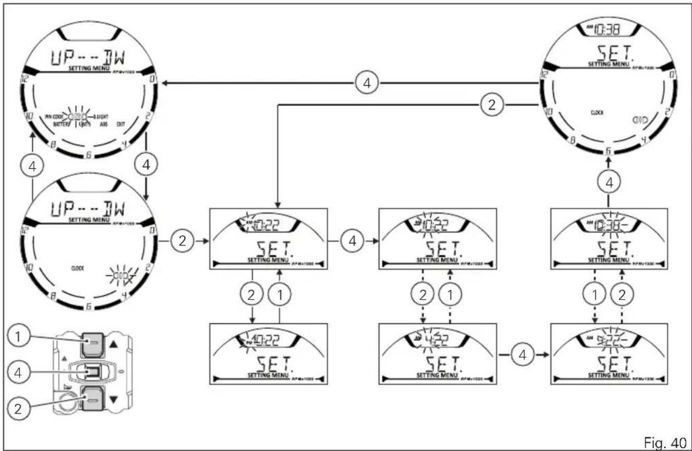
This function allows setting the clock.
To view this function, enter the Setting Menu, use button (1) or (2) to select CLOCK and press button (4).
To access the setting function, keep button (2) pressed for 3 seconds.
After 3 seconds it is possible to set the clock as follows:
- the "AM" indication starts flashing;
- if you press button (2) the "PM" indication starts flashing;
- if you press button (1) you will return to the previous step (if it is 00:00, when switching between "AM" to "PM", 12:00 will be displayed);
- press button (4) to shift to hour setting, hours will start flashing;
- each time you press button (2), the digit will increase by one hour. If you hold button (2) down, the number increases cyclically in steps of one hour every second (when the button is held depressed, the hours do not flash);
- pressing button (4) gives access to the minute setting mode; minutes start to flash;
- each time you press button (2), the digit will increase by 1 minute. If you hold button (2) pressed, the count increases cyclically in steps of 1 minute every second;
- if button (2) is kept pressed for more than 5 seconds, steps increase in steps of 1 every 100 ms (seconds will not flash while button (2) is pressed).
flowchart
graph TD
    A["UP-1W SET. SET. SET. SET. SET. SET. SET. SET. SET. SET. SET. SET. SET. SET. SET. SET. SET. SET. SET. SET. SET. SET. SET. SET. SET. SET. SET. SET. SET. SET. SET. SET. SET. SET. SET. SET. SET. SET. SET. SET. SET. SET. SET. SET. SET. SET. SET. SET. SET. SET. SET, 1, 2, 4"] --> B["2"]
    B --> C["4"]
    C --> D["2"]
    D --> E["4"]
    E --> F["4"]
    F --> G["4"]
    G --> H["4"]
    H --> I["4"]
    I --> J["4"]
    J --> K["4"]
    K --> L["4"]
    L --> M["4"]
    M --> N["4"]
    N --> O["4"]
    O --> P["4"]
    P --> Q["4"]
    Q --> R["4"]
    R --> S["4"]
    S --> T["4"]
    T --> U["4"]
    U --> V["4"]
    V --> W["4"]
    W --> X["4"]
    X --> Y["4"]
    Y --> Z["4"]
To confirm (store) the new set time press button (4).
The EXIT box starts flashing, press button (4) to go back to the setting menu.

Note
In case of battery off, when the Voltage is
restored and upon next Key-On, clock will have to be set again, i.e. it will automatically start counting from 00:00.
To quit, press button (4).
Pin Code
This function allows enabling and then modifying a 4-digit PIN code to "temporarily" start the vehicle in case of Immobilizer system malfunction.
The PIN CODE is initially not present in the motorcycle, it must be activated by the user by entering his/her 4-digit PIN in the instrument panel, otherwise the motorcycle cannot be started temporarily in the case of a malfunction. To activate this function, refer to "Entering the PIN CODE" procedure.
To change the PIN refer to "Changing the PIN CODE" procedure.
In order to temporarily start the motorcycle in case of malfunction of the Immobilizer system, please refer to the "Vehicle Release" procedure.

Warning
The motorcycle owner must activate (store) the PIN code; if there is already a stored PIN, contact an Authorised Ducati Dealer to have the function "reset". To perform this procedure, the Authorised Ducati Dealer may ask you to demonstrate that you are the owner of the motorcycle.
Entering the PIN CODE
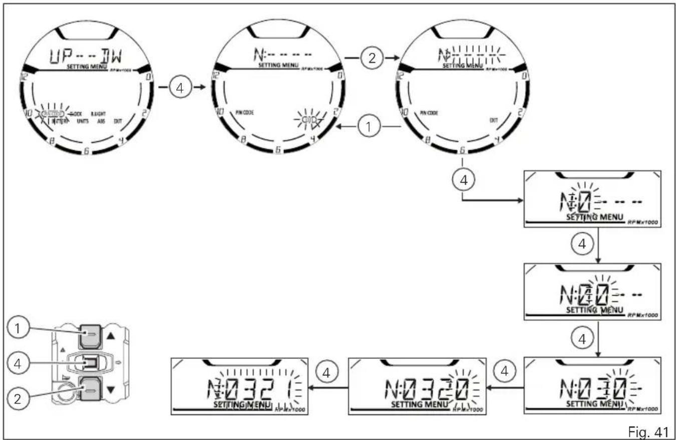
To activate the PIN CODE function and enter your own PIN CODE you must open the SETTING MENU. Select PIN CODE option, by pressing button (1) or (2). Once function is highlighted, press CONFIRM MENU button (4).

Note
If upon accessing this function, the "O : " (Old) indication is displayed together with four flashing dashes "----", a PIN code is already stored and the Function is already active.
When accessing the function, the display will show "N:" (new) followed by four flashing dashes "----". To go back to the previous indication without activating a PIN CODE, press button (2); as soon as the "EXIT" box starts flashing, press button (4) again. Entering the code:
1) Press button (4), only one digit indicating "0" starts flashing;
2) Each time you press button (2) the displayed number increases by one (+ 1) up to "9" and then starts back from "0";
3) Each time you press the button (1) the displayed number decreases by one (-1) up to "1" and then starts back from "0";
4) To confirm the number, press the button (4);
Repeat the procedures until you confirm all the digits of the PIN CODE.
flowchart
graph TD
    A["UP---TW<br>SETTING MENU RPMx1000"] -->|4| B["N:---"]
    B -->|2| C["SETTING MENU RPMx1000"]
    C -->|1| D["SETTING MENU RPMx1000"]
    D -->|4| E["SETTING MENU RPMx1000"]
    E -->|4| F["SETTING MENU RPMx1000"]
    F -->|4| G["SETTING MENU RPMx1000"]
    G -->|4| H["SETTING MENU RPMx1000"]
    H -->|4| I["SETTING MENU RPMx1000"]
    I -->|4| J["SETTING MENU RPMx1000"]
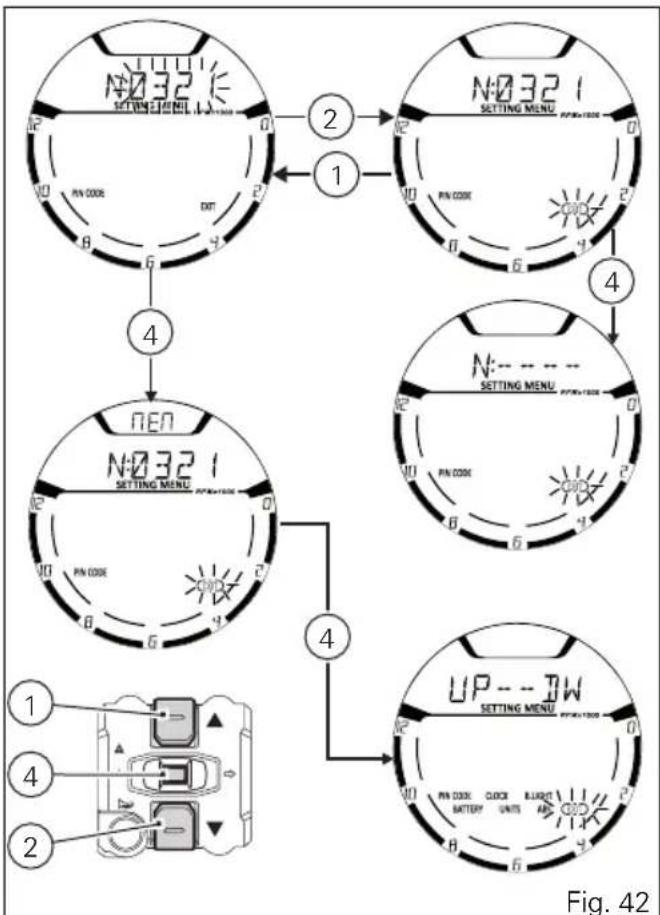
Press button (4) to confirm the fourth and last figure: the 4-digit code starts flashing.
To memorise the entered PIN, keep button (4) pressed for 3 seconds.
If new settings have been saved, "MEM" will be shown and the "EXIT" box will be flashing.
To quit, press button (4).
Once the first PIN CODE is stored, this menu page is no longer available and is replaced by the page for changing the PIN CODE.
flowchart
graph TD
    A["1: SETTING MENU"] --> B["2: SETTING MENU"]
    B --> C["3: SETTING MENU"]
    C --> D["4: SETTING MENU"]
    D --> E["5: SETTING MENU"]
    E --> F["6: SETTING MENU"]
    F --> G["7: SETTING MENU"]
    G --> H["8: SETTING MENU"]
    H --> I["9: SETTING MENU"]
    I --> J["10: SETTING MENU"]
    J --> K["11: SETTING MENU"]
    K --> L["12: SETTING MENU"]
    L --> M["13: SETTING MENU"]
    M --> N["14: SETTING MENU"]
    N --> O["15: SETTING MENU"]
    O --> P["16: SETTING MENU"]
    P --> Q["17: SETTING MENU"]
    Q --> R["18: SETTING MENU"]
    R --> S["19: SETTING MENU"]
    S --> T["20: SETTING MENU"]
    T --> U["21: SETTING MENU"]
    U --> V["22: SETTING MENU"]
    V --> W["23: SETTING MENU"]
    W --> X["24: SETTING MENU"]
    X --> Y["25: SETTING MENU"]
    Y --> Z["26: SETTING MENU"]
    Z --> AA["27: SETTING MENU"]
    AA --> AB["28: SETTING MENU"]
    AB --> AC["29: SETTING MENU"]
    AC --> AD["30: SETTING MENU"]
    AD --> AE["31: SETTING MENU"]
    AE --> AF["32: SETTING MENU"]
    AF --> AG["33: SETTING MENU"]
    AG --> AH["34: SETTING MENU"]
    AH --> AI["35: SETTING MENU"]
    AI --> AJ["36: SETTING MENU"]
    AJ --> AK["37: SETTING MENU"]
    AK --> AL["38: SETTING MENU"]
    AL --> AM["39: SETTING MENU"]
    AM --> AN["40: SETTING MENU"]
    AN --> AO["41: SETTING MENU"]
    AO --> AP["42: SETTING MENU"]
Changing the PIN CODE
To change the existing PIN CODE and activate a new one, you must open the SETTING MENU.
Select PIN CODE option, by pressing button (1) or (2). Once function is highlighted, press CONFIRM MENU button (4).

Note
If upon accessing this function, the "N : " (New) and four flashing dashes "----" are shown, it means that the PIN CODE has never been activated and it is necessary to do it.
When accessing the function, the display will show "O:" (old) followed by four flashing dashes "----".

Note
To change the PIN CODE, you must know the already stored PIN.
To go back to the previous indication without modifying the PIN CODE, press button (2); as soon as the "EXIT" box starts flashing, press button (4) again.
Entering the "old" code:
1) Press button (4), only one digit indicating "0" starts flashing;
2) Each time you press button (2) the displayed number increases by one (+ 1) up to "9" and then starts back from "0";
3) Each time you press the button (1) the displayed number decreases by one (-1) up to "1" and then starts back from "0";
4) To confirm the number, press the button (4);
Repeat the procedures until you confirm all the digits of the PIN CODE.
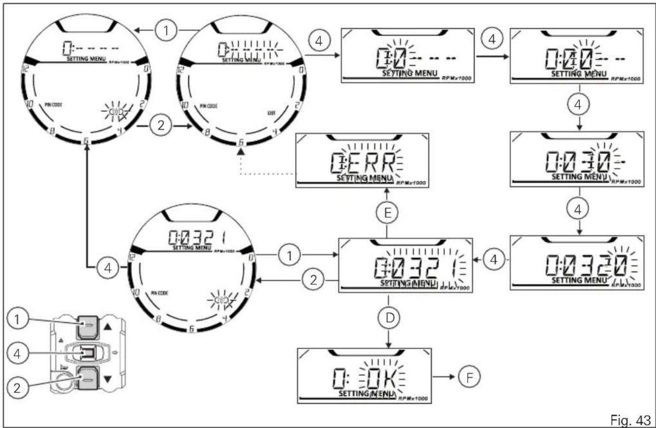
flowchart
graph TD
    A["1 SETTING MENU RPM×1000"] --> B["2 SETTING MENU RPM×1000"]
    B --> C["3 SETTING MENU RPM×1000"]
    C --> D["4 SETTING MENU RPM×1000"]
    D --> E["5 ERR SETTING MENU RPM×1000"]
    E --> F["6 SETTING MENU RPM×1000"]
    F --> G["7 SETTING MENU RPM×1000"]
    G --> H["8 SETTING MENU RPM×1000"]
    H --> I["9 SETTING MENU RPM×1000"]
    I --> J["10 SETTING MENU RPM×1000"]
    J --> K["11 SETTING MENU RPM×1000"]
    K --> L["12 SETTING MENU RPM×1000"]
    L --> M["13 SETTING MENU RPM×1000"]
    M --> N["14 SETTING MENU RPM×1000"]
    N --> O["15 SETTING MENU RPM×1000"]
    O --> P["16 SETTING MENU RPM×1000"]
    P --> Q["17 SETTING MENU RPM×1000"]
    Q --> R["18 SETTING MENU RPM×1000"]
    R --> S["19 SETTING MENU RPM×1000"]
    S --> T["20 SETTING MENU RPM×1000"]
    T --> U["21 SETTING MENU RPM×1000"]
    U --> V["22 SETTING MENU RPM×1000"]
    V --> W["23 SETTING MENU RPM×1000"]
    W --> X["24 SETTING MENU RPM×1000"]
    X --> Y["25 SETTING MENU RPM×1000"]
    Y --> Z["26 SETTING MENU RPM×1000"]
    Z --> AA["27 SETTING MENU RPM×1000"]
    AA --> AB["28 SETTING MENU RPM×1000"]
    AB --> AC["29 SETTING MENU RPM×1000"]
    AC --> AD["30 SETTING MENU RPM×1000"]
    AD --> AE["31 SETTING MENU RPM×1000"]
    AE --> AF["32 SETTING MENU RPM×1000"]
    AF --> AG["33 SETTING MENU RPM×1000"]
    AG --> AH["34 SETTING MENU RPM×1000"]
    AH --> AI["35 SETTING MENU RPM×1000"]
    AI --> AJ["36 SETTING MENU RPM×1000"]
    AJ --> AK["37 SETTING MENU RPM×1000"]
    AK --> AL["38 SETTING MENU RPM×1000"]
    AL --> AM["39 SETTING MENU RPM×1000"]
    AM --> AN["40 SETTING MENU RPM×1000"]
    AN --> AO["41 SETTING MENU RPM×1000"]
    AO --> AP["42 SETTING MENU RPM×1000"]
    AP --> AQ["43 SETTING MENU RPM×1000"]
After pressing button (4) to confirm the fourth and last figure, the 4-digit code starts flashing.
Press button (4) to check the entered PIN CODE.
After you press the button:
- if the PIN CODE is correct (D), the instrument panel shows "OK" flashing for 3 seconds, followed by "N: " (new) and four flashing dashes "----" relevant to the new PIN CODE (F);
- if the PIN CODE is not correct (E), the instrument panel shows ERR. flashing for 3 seconds, followed by "O: " (old) and four flashing dashes "-" to enter the PIN again.
Repeat the procedures until you confirm all the digits of the PIN CODE.
Entering the "new" code:
1) Press button (4), only one digit indicating "0" starts flashing;
2) Each time you press button (2) the displayed number increases by one (+ 1) up to "9" and then starts back from "0";
3) Each time you press the button (1) the displayed number decreases by one (-1) up to "1" and then starts back from "0";
4) To confirm the number, press the button (4);
Repeat the procedures until you confirm all the digits of the PIN CODE.
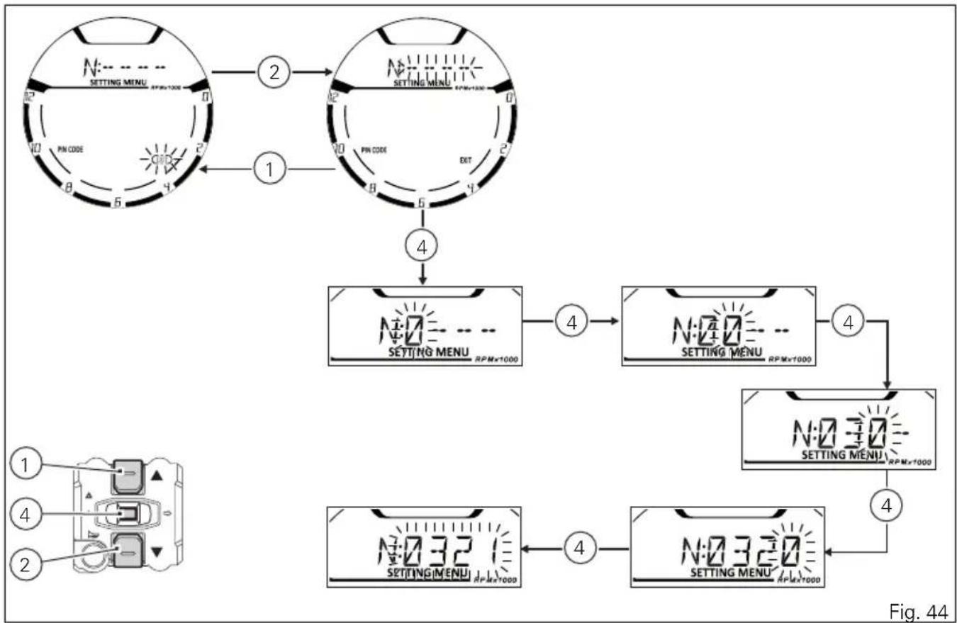
flowchart
graph TD
    A["SETTING MENU RPM×1000"] --> B["2"]
    B --> C["1"]
    C --> D["4"]
    D --> E["4"]
    E --> F["4"]
    F --> G["4"]
    G --> H["4"]
    H --> I["4"]
    I --> J["4"]
    J --> K["4"]
    K --> L["4"]
    L --> M["4"]
Press button (4) to confirm the fourth and last figure: the 4-digit code starts flashing.
To memorise the new setting, keep button (4) pressed for 3 seconds.
If new settings have been saved (D), "MEM" will be shown, the "EXIT" option will be highlighted and its box will be flashing.
To quit, press button (4).
If settings have not been saved, the instrument panel will highlight again the string of four dashes "----" of the new PIN to allow the rider to try again and enter a new code.

Note
You can change your PIN CODE an unlimited number of times.
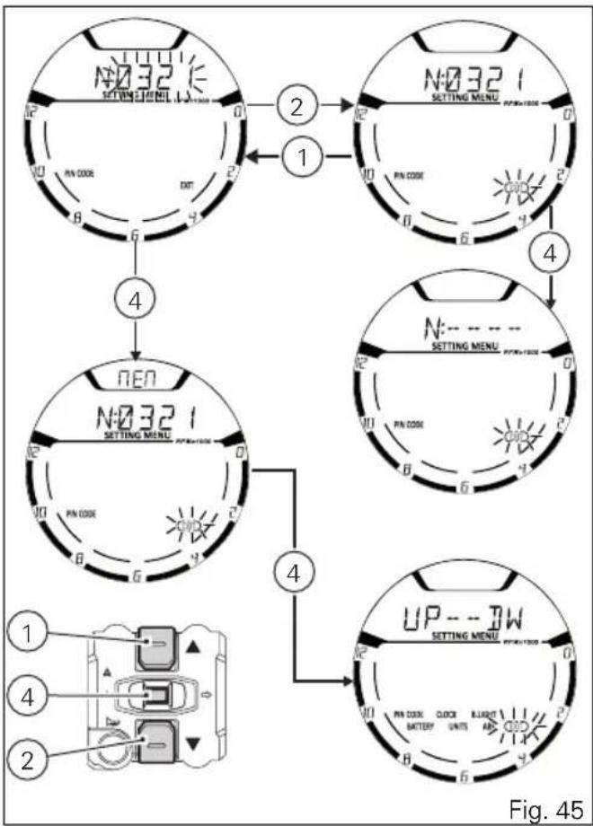
flowchart
graph TD
    A["1: SETTING MENU"] --> B["2: SETTING MENU"]
    B --> C["3: SETTING MENU"]
    C --> D["4: SETTING MENU"]
    D --> E["5: UP-UP"]
    E --> F["6: UP-UP"]
    F --> G["7: UP-UP"]
    G --> H["8: UP-UP"]
    H --> I["9: UP-UP"]
    I --> J["10: UP-UP"]
Setting the units of measurement
This function allows changing the units of measurement of the displayed values.
To manually set the units of measurement, you must enter the SETTING MENU.
Select UNITS option, by pressing button (1) or (2).
Once function is highlighted, press CONFIRM MENU button (4).
When entering this function, use buttons (1) and (2) to select the parameter for which you want to set a new unit of measurement or to restore the default settings:
- SPEED;
- temperature (TEMP.);
- restore the default settings for units of measurement (UNIT:DF).
To exit the menu and go back to the previous page, select "EXIT" and press button (4).
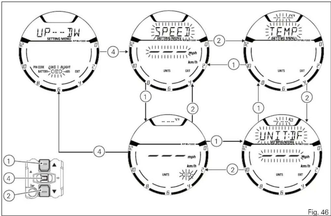
flowchart
graph TD
    A["UP --- TW<br>SETTING MENU<br>RPM=1000"] -->|4| B["SPEED<br>GDTING MENU<br>RPM=1000"]
    B -->|2| C["TEMP<br>GDTING MENU<br>RPM=1000"]
    C -->|1| D["UNIT:DF<br>SETTING MENU<br>RPM=1000"]
    D -->|2| E["UNIT:TF"]
    E -->|1| F["UNIT:TF"]
    F -->|2| G["UNIT:TF"]
    G -->|4| H["UNIT:TF"]
    H -->|4| I["UNIT:TF"]
    I -->|1| J["UNIT:TF"]
    J -->|2| K["UNIT:TF"]
    K -->|4| L["UNIT:TF"]
    L -->|4| M["UNIT:TF"]
    M -->|1| N["UNIT:TF"]
    N -->|2| O["UNIT:TF"]
    O -->|4| P["UNIT:TF"]
    P -->|4| Q["UNIT:TF"]
    Q -->|1| R["UNIT:TF"]
    R -->|2| S["UNIT:TF"]
    S -->|4| T["UNIT:TF"]
    T -->|4| U["UNIT:TF"]
    U -->|1| V["UNIT:TF"]
    V -->|2| W["UNIT:TF"]
    W -->|4| X["UNIT:TF"]
    X -->|4| Y["UNIT:TF"]
Setting the units of measurement: Speed
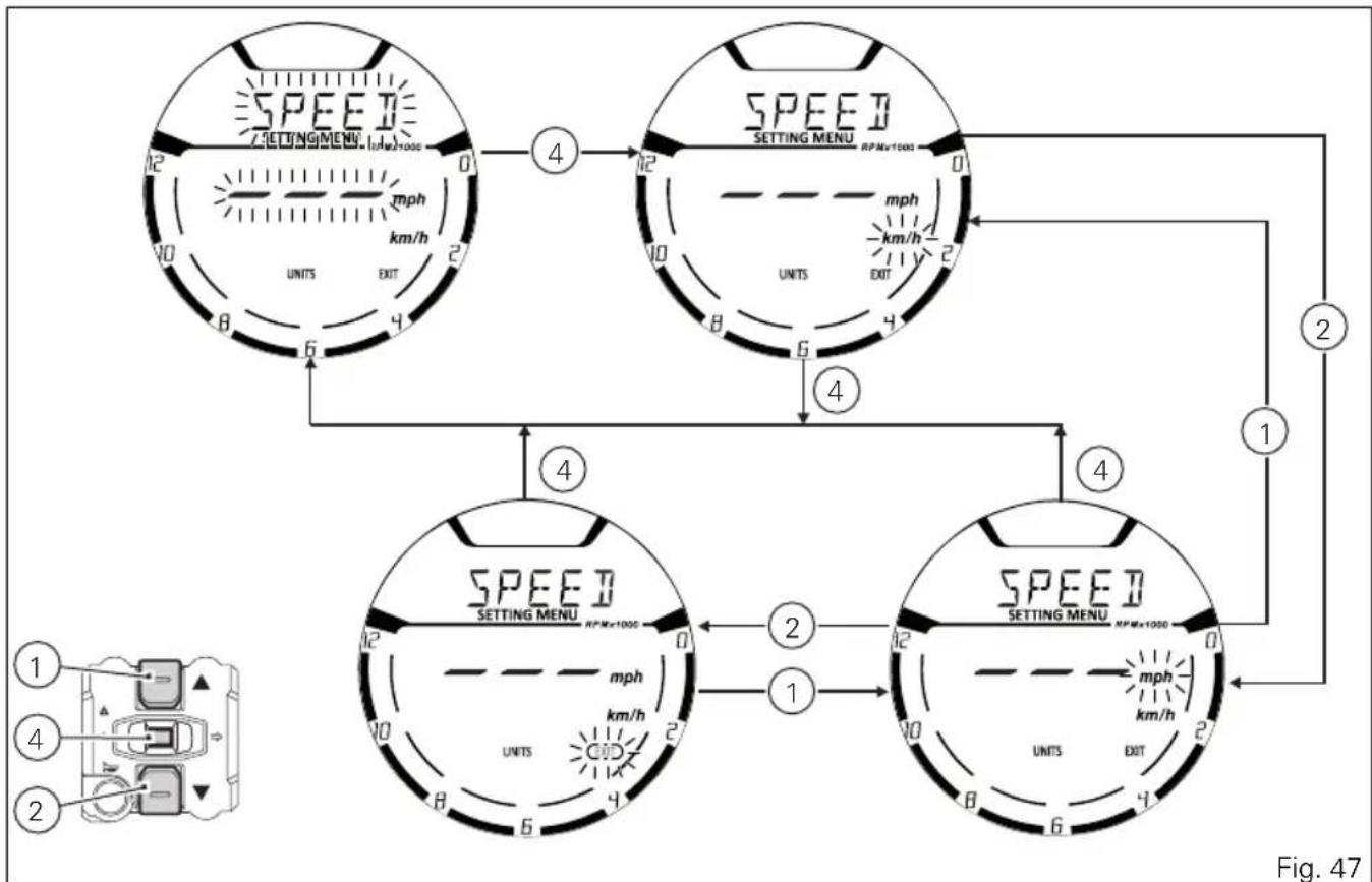
This function allows changing the unit of measurement of Vehicle speed, Odometer, Trip 1, Trip 2 and Trip Fuel (when active). To gain access to this function enter the SETTING MENU, use buttons (1) and (2) to select UNITS and press button (4). Select SPEED option, by pressing button (1) or (2).
Once SPEED function is highlighted, press CONFIRM MENU button (4). When entering the function, units of measurement (mph, km/h) are indicated: current unit of measurement is flashing while the other available unit is not flashing. Press buttons (1) and (2) to highlight the units of measurement one by one: in particular, use button (1) to highlight the following item and button (2) to highlight the previous item. Select the required unit of measurement and then press the CONFIRM MENU button (4) to confirm the selected unit; then the selected unit of measurement is saved in the instrument panel and the SPEED indication starts flashing again.
Press button (2) to make the EXIT box flash; press button (4) to quit and go back to the previous window.
- Km/h: if this unit is set, the following values will have the same units of measurement:
- mph: if this unit is set, the following values will have the same units of measurement:
1) TOT, TRIP 1, TRIP 2, TRIP FUEL: miles
2) Motorcycle speed: mph
flowchart
graph TD
    A["Top Section"] -->|4| B["Top Section"]
    B -->|12| C["Bottom Section"]
    C -->|2| D["Bottom Section"]
    D -->|4| E["Bottom Section"]
    E -->|12| F["Bottom Section"]
    F -->|2| G["Bottom Section"]
    G -->|4| H["Bottom Section"]
    H -->|12| I["Bottom Section"]
    I -->|2| J["Bottom Section"]
    J -->|4| K["Bottom Section"]
    K -->|12| L["Bottom Section"]
    L -->|2| M["Bottom Section"]
    M -->|4| N["Bottom Section"]
    N -->|12| O["Bottom Section"]
    O -->|2| P["Bottom Section"]
    P -->|4| Q["Bottom Section"]
    Q -->|12| R["Bottom Section"]
    R -->|2| S["Bottom Section"]
    S -->|4| T["Bottom Section"]
    T -->|12| U["Bottom Section"]
    U -->|2| V["Bottom Section"]
    V -->|4| W["Bottom Section"]
Setting the units of measurement: Temperature
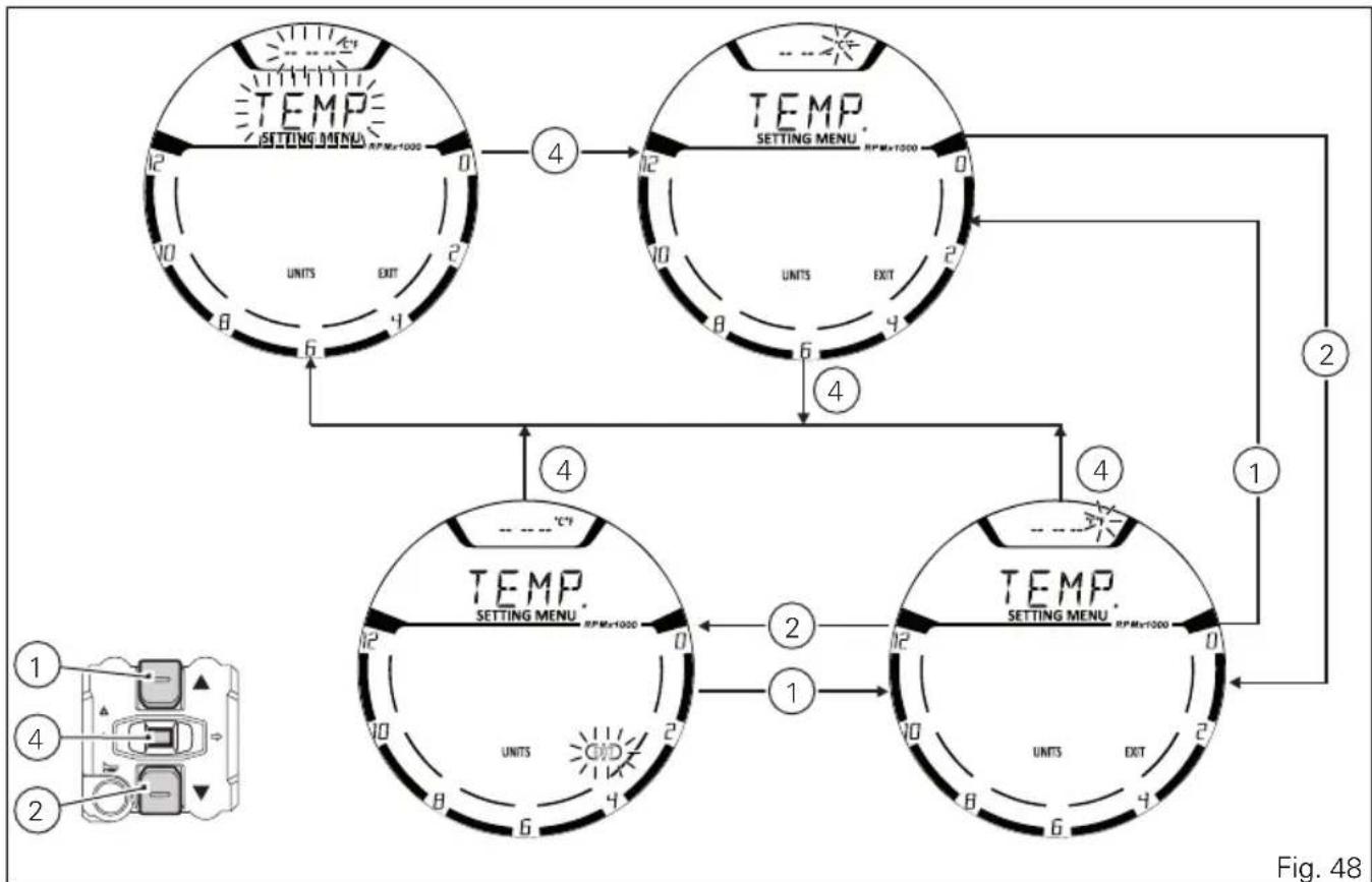
This function allows you to change the units of measurement of the Air Temperature indications. To gain access to this function enter the SETTING MENU, use buttons (1) and (2) to select UNITS and press button (4).
Select TEMP option, by pressing button (1) or (2). Once TEMP. function is highlighted, press CONFIRM MENU button (4).
When entering the function, units of measurement (°C, °F) are indicated: current unit of measurement is flashing while the other available unit is not flashing. Press buttons (1) and (2) to highlight the units of measurement one by one: in particular, use button (1) to highlight the following item and button (2) to highlight the previous item. Select the required unit of measurement and then press the CONFIRM MENU button (4) to confirm the selected unit; then the selected unit of measurement is saved in the instrument panel and the "TEMP." indication starts flashing again.
Press button (2) to make the EXIT box flash; press button (4) to quit and go back to the previous window.
- °C: if this unit is set, the following values will have the same units of measurement:
1) T - AIR: °C
- °F: if this unit is set, the following values will have the same units of measurement:
1) T - AIR: °F
flowchart
graph TD
    A["TEMP SETTING MENU RPM=1000"] -->|4| B["TEMP SETTING MENU RPM=1000"]
    B -->|2| C["TEMP SETTING MENU RPM=1000"]
    C -->|4| D["TEMP SETTING MENU RPM=1000"]
    D -->|2| E["TEMP SETTING MENU RPM=1000"]
    E -->|4| F["TEMP SETTING MENU RPM=1000"]
    F -->|2| G["TEMP SETTING MENU RPM=1000"]
    G -->|4| H["TEMP SETTING MENU RPM=1000"]
    H -->|2| I["TEMP SETTING MENU RPM=1000"]
    I -->|4| J["TEMP SETTING MENU RPM=1000"]
    J -->|2| K["TEMP SETTING MENU RPM=1000"]
    K -->|4| L["TEMP SETTING MENU RPM=1000"]
    L -->|2| M["TEMP SETTING MENU RPM=1000"]
    M -->|4| N["TEMP SETTING MENU RPM=1000"]
    N -->|2| O["TEMP SETTING MENU RPM=1000"]
    O -->|4| P["TEMP SETTING MENU RPM=1000"]
    P -->|2| Q["TEMP SETTING MENU RPM=1000"]
    Q -->|4| R["TEMP SETTING MENU RPM=1000"]
    R -->|2| S["TEMP SETTING MENU RPM=1000"]
    S -->|4| T["TEMP SETTING MENU RPM=1000"]
    T -->|2| U["TEMP SETTING MENU RPM=1000"]
    U -->|4| V["TEMP SETTING MENU RPM=1000"]
    V -->|2| W["TEMP SETTING MENU RPM=1000"]
    W -->|4| X["TEMP SETTING MENU RPM=1000"]
    X -->|2| Y["TEMP SETTING MENU RPM=1000"]
    Y -->|4| Z["TEMP SETTING MENU RPM=1000"]
DEFAULT setting
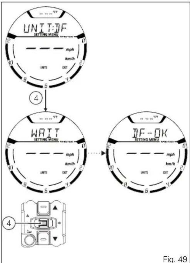
This function allows setting the DEFAULT units of measurement according to the vehicle version. To gain access to this function enter the SETTING MENU, use buttons (1) and (2) to select UNITS and press button (4). Press button (1) or (2) to make the "UNIT:DF" option start flashing and then press button (4) for 3 seconds.
After 3 seconds the instrument panel shows "WAIT" for 2 seconds; then the "DF-OK" message indicates that the units of measurement have been restored.
flowchart
graph TD
    A["UNIT:DF SETTING MENU RPM=1000"] --> B["mph km/h"]
    B --> C["EXIT 2"]
    C --> D["Units 6"]
    D --> E["4"]
    E --> F["WAIT SETTING MENU RPM=1000"]
    F --> G["mph km/h"]
    G --> H["EXIT 2"]
    H --> I["Units 6"]
    I --> J["4"]
    J --> K["UNIT:DF SETTING MENU RPM=1000"]
    K --> L["mph km/h"]
    L --> M["EXIT 2"]
    M --> N["Units 6"]
    N --> O["4"]
    O --> P["UNIT:DF SETTING MENU RPM=1000"]
    P --> Q["mph km/h"]
    Q --> R["EXIT 2"]
    R --> S["Units 6"]
    S --> T["4"]
    T --> U["UNIT:DF SETTING MENU RPM=1000"]
    U --> V["mph km/h"]
    V --> W["EXIT 2"]
    W --> X["Units 6"]
    X --> Y["4"]
Light control
Low / High beam
This function allows you to reduce current consumption from the battery, by managing headlight switching-on and off.
Upon Key-On, low and high beams remain off (OFF). By starting the engine, the low beam will be automatically activated; from now on, the "standard" operation will become active, i.e. it will be possible to switch from low to high beam by pressing button (3) in position (V) or use the "FLASH" function by pressing button (3) in position (O). If engine is not started upon key-on, it is anyway possible to switch the lights on by pushing the button on the LH high/low beam switch: button (3) in position (V).
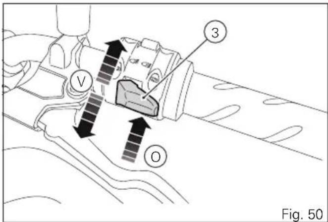
The low beam lights are turned on the first time it is pressed; from this moment, the same button can be used to switch on (and off) the high beam light: if the engine is not started within 60 seconds, the low beam and high beam that were turned on will turn off. If the headlight was turned on before starting the engine with the procedure described above, the headlight will turn off automatically when starting the vehicle and will turn ON again when the engine has been completely started.
Turn indicators
Turn indicators are automatically controlled by the instrument panel.
After activating one of the two turn indicators, user can reset them using the button (3, Fig. 50) on the left switch.
If the turn indicator is not reset manually, the instrument panel will automatically switch it off after the motorcycle has travelled 500 m (0.3 miles) from when the turn indicator was activated. The counter for the distance travelled for automatic deactivation is only activated at speeds below 80 km/h (50 mph). If the calculation of the distance for automatic deactivation is activated and then the motorcycle exceeds a speed of 80 km/h (50 mph), the calculation
will be interrupted and will restart when the speed returns below the indicated threshold.
Hazard function
The "Hazard" function turns all four turn indicators on at the same time to signal an emergency condition. The "Hazard" function is activated by taking button (3) to position (6) for 3 seconds. Activation is only possible when motorcycle is ON (i.e. when key is turned to "ON" while engine status does not matter). When the "Hazard" function is active, all four turn indicators blink at the same time as well as warning lights (7) on the instrument panel. The "Hazard" function can be disabled both with motorcycle on (key set to "ON") - by taking button (3) to position (6) or by taking button (3) to its central position - and with motorcycle off (key set to OFF) by taking button (3) to position (6).
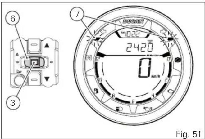
After activating the "Hazard" function, if motorcycle is switched OFF (key set to OFF), the function will stay active until manually disabled by user or it will be automatically disabled after 120 minutes (2 hours) to save battery charge.
Immobilizer system
To further improve the anti-theft protection, the motorcycle is equipped with an engine electronic block system (IMMOBILIZER) that is automatically activated every time the instrument panel is switched off.
Inside of each key handgrip there is an electronic device that modulates the signal sent by a special antenna integrated in the ignition switch upon starting.
Such modulated signal represents the "password", that changes upon every starting, that allows the control unit to acknowledge the key and thus starting the engine.
Keys
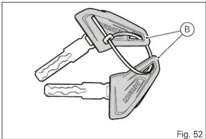
The motorcycle comes with 2 keys. They contain the "Immobilizer system code". Keys (B) are those for the standard use, i.e. to:
- start the engine;
- open the fuel tank plug;
- open the seat lock.

Warning
Separate the keys and use only one of the two to ride the bike.
Operation
Every time you turn the key from ON to OFF, the protection system activates the engine block. If also in this case you are not able to start the engine, contact an authorised Ducati service centre.

Warning
Strong impacts could damage the electronic components inside the key. During the procedure always use the same key. Using different keys may prevent the system from acknowledging the code of the inserted key.
Duplicate keys
When a customer needs spare keys, he/she shall contact a Ducati authorised service centre and bring all keys he/she still has.
The Ducati authorised service centre will program all new and old keys.
The Ducati authorised service centre may ask to the customer to prove to be the motorcycle owner.
The codes of the keys missing during the programming procedure will be erased to ensure that any lost key can not start the engine.

Note
If the motorcycle owner changes, it is necessary that the new owner is given all keys.
Entering PIN CODE function for overriding purposes
In case of key acknowledgement system or key malfunction, the instrument panel allows the user to enter his/her own PIN CODE to temporarily restore motorcycle operation.
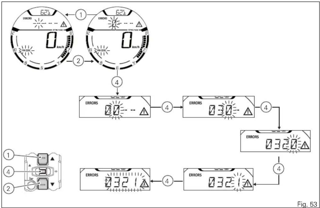
If upon key-on an Immobilizer ERROR occurs, the instrument panel automatically activates in MENU 1 the possibility to enter the four-digit PIN CODE previously memorised with the relevant function in the Setting Menu, PIN page.
Entering the code (A):
1) Press button (2) or (1), only one digit indicating "0" starts flashing;
2) Each time you press button (2) the displayed number increases by one (+ 1) up to "9" and then starts back from "0";
3) Each time you press the button (1) the displayed number decreases by one (-1) up to "1" and then starts back from "0";
4) To confirm the number, press the button (4);
Repeat the procedures until you confirm all the digits of the PIN CODE.
flowchart
graph TD
    A["1: Display 62±1"] --> B["2: Display 62±1"]
    B --> C["4: Display 32±1"]
    C --> D["4: Display 32±1"]
    D --> E["4: Display 32±1"]
    E --> F["4: Display 32±1"]
When you press button (4) to confirm the fourth and last digit:
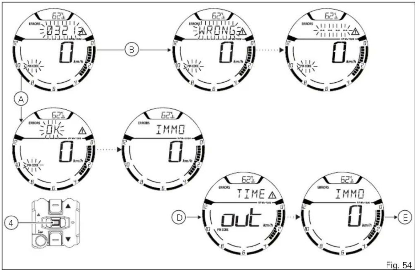
- if the PIN code (A) is correct, the instrument panel shows the message OK for 2 seconds followed by the "standard screen" and enables the vehicle to start (C);
- if the PIN code (B) is not correct, the instrument panel displays WRONG for 2 seconds and then highlights the string of four dashes "----" to allow you to try again. The number of possible attempts is unlimited and determined by a preset time-out of 2 minutes (D). After 2 minutes, the instrument panel shows the standard screen and does not allow the vehicle to start (E).

Important
If this procedure is necessary in order to start the motorcycle, contact an Authorised Ducati Service Centre as soon as possible to fix the problem.

Note
The vehicle can be started until a Key-Off is performed. If the problem still persists upon the next starting attempt, repeat the procedure from the beginning in order to start the motorcycle temporarily again.
flowchart
graph TD
    A["62± 032.1A"] --> B["62± 0 km/h"]
    B --> C["62± 0 km/h"]
    C --> D["62± 0 km/h"]
    D --> E["62± 0 km/h"]
    E --> F["62± 0 km/h"]
    F --> G["62± 0 km/h"]
    G --> H["62± 0 km/h"]
    H --> I["62± 0 km/h"]
    I --> J["62± 0 km/h"]
    J --> K["62± 0 km/h"]
    K --> L["62± 0 km/h"]
    L --> M["62± 0 km/h"]
    M --> N["62± 0 km/h"]
    N --> O["62± 0 km/h"]
    O --> P["62± 0 km/h"]
    P --> Q["62± 0 km/h"]
    Q --> R["62± 0 km/h"]
    R --> S["62± 0 km/h"]
    S --> T["62± 0 km/h"]
    T --> U["62± 0 km/h"]
    U --> V["62± 0 km/h"]
    V --> W["62± 0 km/h"]
    W --> X["62± 0 km/h"]
    X --> Y["62± 0 km/h"]
    Y --> Z["62± 0 km/h"]
    Z --> AA["62± 0 km/h"]
    AA --> AB["62± 0 km/h"]
    AB --> AC["62± 0 km/h"]
    AC --> AD["62± 0 km/h"]
    AD --> AE["62± 0 km/h"]
    AE --> AF["62± 0 km/h"]
    AF --> AG["62± 0 km/h"]
    AG --> AH["62± 0 km/h"]
    AH --> AI["62± 0 km/h"]
    AI --> AJ["62± 0 km/h"]
    AJ --> AK["62± 0 km/h"]
    AK --> AL["62± 0 km/h"]
    AL --> AM["62± 0 km/h"]
    AM --> AN["62± 0 km/h"]
    AN --> AO["62± 0 km/h"]
    AO --> AP["62± 0 km/h"]
    AP --> AQ["62± 0 km/h"]
    AQ --> AR["62± 0 km/h"]
    AR --> AS["62± 0 km/h"]
    AS --> AT["62± 0 km/h"]
    AT --> AU["62± 0 km/h"]
    AU --> AV["62± 0 km/h"]
    AV --> AW["62± 0 km/h"]
    AW --> AX["62± 0 km/h"]
    AX --> AY["62± 0 km/h"]
    AY --> AZ["62± 0 km/h"]
    AZ --> BA["62± 0 km/h"]
    BA --> BB["62± 0 km/h"]
    BB --> BC["62± 0 km/h"]
    BC --> BD["62± 0 km/h"]
    BD --> BE["62± 0 km/h"]
    BE --> BF["62± 0 km/h"]
    BF --> BG["62± 0 km/h"]
    BG --> BH["62± 0 km/h"]
    BH --> BI["62± 0 km/h"]
    BI --> BJ["62± 0 km/h"]
    BJ --> BK["62± 0 km/h"]
    BK --> BL["62± 0 km/h"]
    BL --> BM["62± 0 km/h"]
    BM --> BN["62± 0 km/h"]
    BN --> BO["62± 0 km/h"]
    BO --> BP["62± 0 km/h"]
    BP --> BQ["62± 0 km/h"]
    BQ --> BR["62± 0 km/h"]
    BR --> BS["62± 0 km/h"]
    BS --> BT["62± 0 km/h"]
    BT --> BU["62± 0 km/h"]
    BU --> BV["62± 0 km/h"]
    BV --> BW["62± 0 km/h"]
    BW --> BX["62± 0 km/h"]
    BX --> BY["62± 0 km/h"]
    BY --> BZ["62± 0 km/h"]
    BZ --> CA["62± 0 km/h"]
    CA --> CB["62± 0 km/h"]
    CB --> CC["62± 0 km/h"]
    CC --> CD["62± 0 km/h"]
    CD --> CE["62± 0 km/h"]
    CE --> CF["62± 0 km/h"]
    CF --> CG["62± 0 km/h"]
    CG --> CH["62± 0 km/h"]
    CH --> CI["62± 0 km/h"]
    CI --> CJ["62± 0 km/h"]
    CJ --> CK["62± 0 km/h"]
Controls
Position of motorcycle controls

Warning
This section shows the position and function of the controls used to ride the motorcycle. Be sure to read this information carefully before you use the controls.
1) Instrument panel.
2) Key-operated ignition switch and steering lock.
3) Left-hand switch.
4) Clutch lever.
5) Rear brake pedal.
6) Right-hand switch.
7) Throttle twistgrip.
8) Front brake lever.
9) Gear change pedal.
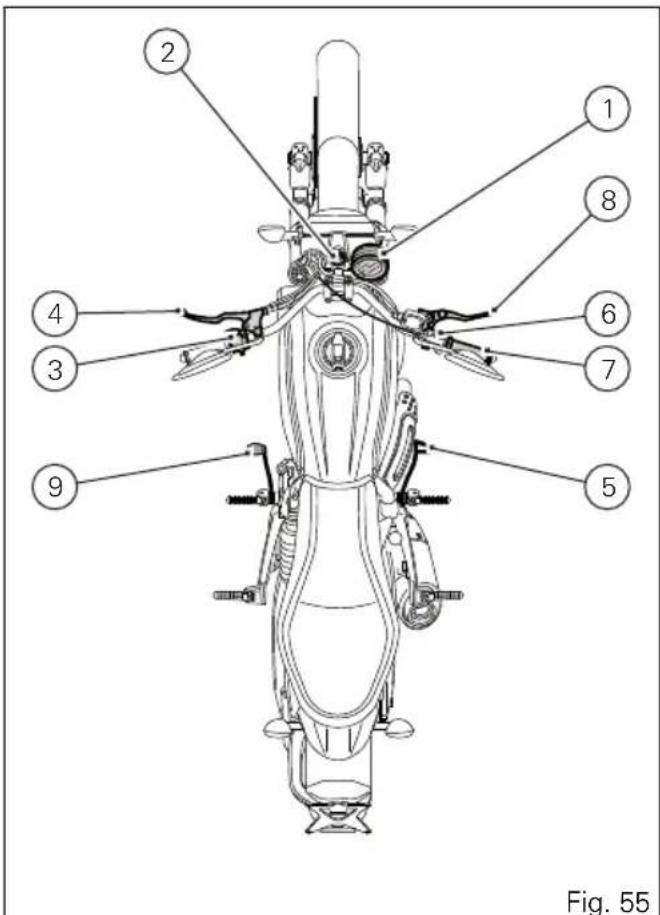
Key-operated ignition switch and steering lock
It is located in front of the fuel tank and has four positions:
A) ☐enables lights and engine operation;
B) ☒ : disables lights and engine operation;
C) 🔒 : the steering is locked;
D) parking light and steering lock.

Note
To move the key to the last two positions, press it down before turning it. The key can be removed in positions (B), (C) and (D).
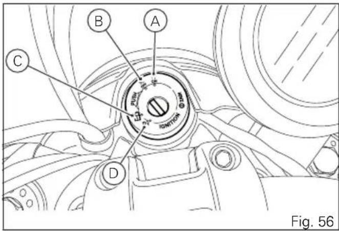
Left-hand switch
1) dip switch, two-position light selector switch: position ☐ low beam ON (A); position ☐ high beam ON (B); Button ☐ high-beam flasher (FLASH) and instrument panel control (C).
2) Switch 3-position turn indicator control: centre position = OFF; position ← = left turn; position → = right turn. To disable the turn indicator, press the control once it returns to centre position.
3) Button ▶ = warning horn. 4) Instrument panel control switch, position " " 5) Instrument panel control switch, position "
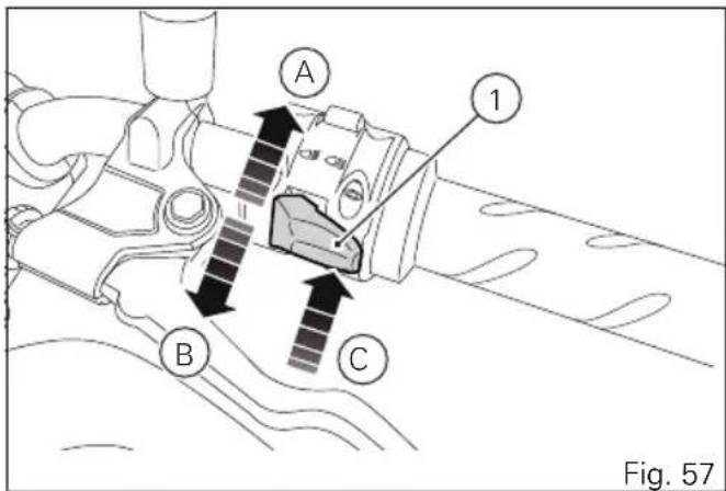
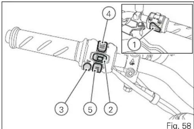
Clutch lever
Lever (1) disengages the clutch. When clutch lever (1) is operated, the drive from the engine to the gearbox and the drive wheel is disengaged. Using the clutch properly is essential to smooth riding, especially when moving off.

Important
Using the clutch properly will avoid damage to transmission parts and spare the engine.

Note
The engine can be started with the side stand down and the gearbox in neutral. If starting with a gear engaged, pull in the clutch lever (in this case the side stand must be up).
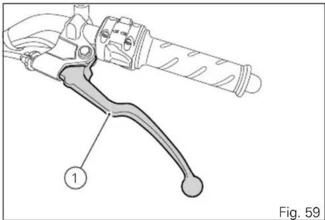
natural_image
Technical line drawing of a brake lever with labeled component (1), no text or symbols presentClutch control free play adjustment

Warning
A wrong adjustment can seriously affect the clutch operation and service life.
A worn clutch tensions the clutch cable.
Always check the free play, with cold engine, before using the vehicle.
When operating the clutch lever, you must clearly feel the passage from a very low resistance to a very high resistance (operating force).
The free play corresponds to the lever travel where the clutch resistance force is very low.
Operate the lever for its free play and check that distance "A" is between 3 - 4 mm.
To adjust the free play make sure that it is not equal to zero. Work on the primary adjuster (2) near the clutch control.
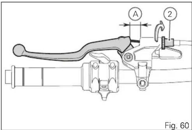
Adjuster (2), located on the lever, allows a maximum adjustment (Q) of 11 mm, whereas the standard adjustment (starting one) is of 5 mm. If working on such adjuster proves insufficient, work on the secondary adjuster (3).

Warning
In case of a slipping clutch due to clutch wear, adjuster (2) on the lever must NEVER be loosened, but screwed, as described above. If the clutch is still slipping, go to a Dealer or a Ducati authorised service centre.
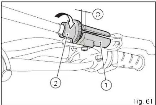
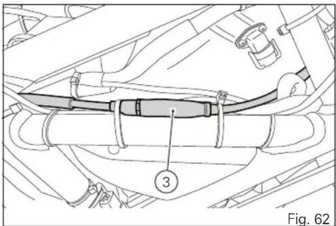
Right-hand switch
1) Red ON/OFF switch.
2) Black ENGINE START button.
The switch (1) has three positions:
A) centre: RUN OFF. In this position, the engine cannot be started and all electronic devices are OFF.
B) pushed down: ON/OFF. In this position, the system can be turned ON (Key-ON) and OFF (Key-OFF).
C) pushed up: RUN ON. The engine can only be started in this position, pushing the black button (2).
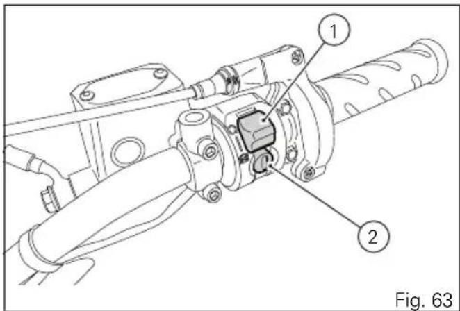
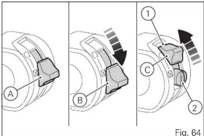
Throttle twistgrip
The twistgrip (1) on the right handlebar opens the throttles. When released, it will spring back to the initial position (idling speed).
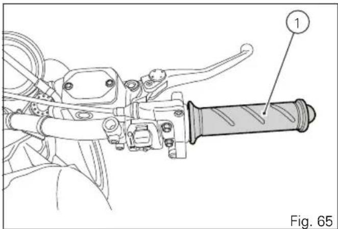
Front brake lever
Pull in the lever (1) towards the twistgrip to operate the front brake. The system is hydraulically operated and you just need to pull the lever gently. The brake lever has a dial adjuster (2) for adjusting the distance between lever and twistgrip on the handlebar. To adjust it, keep lever (1) fully extended, and turn dial adjuster (2), turning it in correspondence of one of the four foreseen positions. Keep in mind that the position no. 1 corresponds to the maximum distance between the lever and the handgrip, whereas position no. 4 corresponds to the minimum distance.
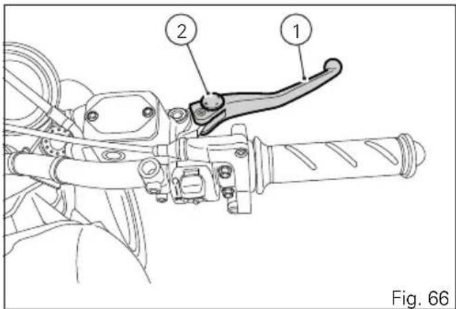

Warning
Set front brake lever when motorcycle is stopped.
Rear brake pedal
Press pedal down with your foot to operate the rear brake (1).
The control system is of the hydraulic type.
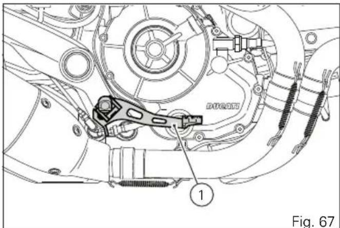
Gear change pedal
When released, the gear change pedal automatically returns to rest position N in the centre. This is indicated by the instrument panel N light coming on. The pedal can be moved:
down = press down the pedal to engage the 1^st gear and to shift down. The N light on the instrument panel will go out;
upwards= lift the pedal to engage 2^nd gear and then 3^rd , 4^th , 5^th and 6^th gears.
Each time you move the pedal you will engage the next gear.
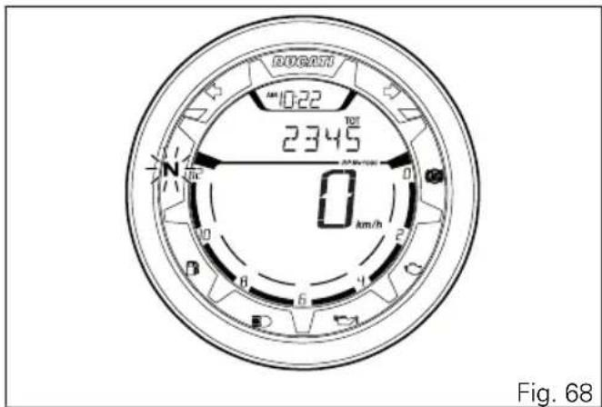
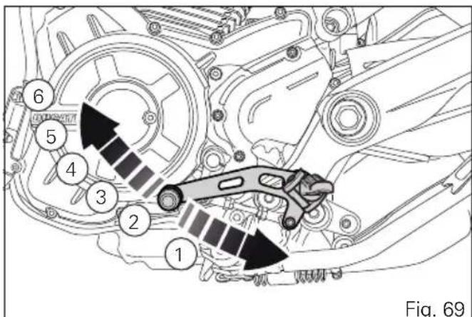
Adjusting the position of the gearchange pedal and rear brake pedal
The position of the gearchange and rear brake pedals in relation to the footrests can be adjusted to suit the requirements of the rider.
Adjust the pedals as follows:
Gear change pedal
Hold the linkage (1) and slacken the lock nuts (2) and (3).

Note
Nut (2) has a left-hand thread.
Fit an open-end wrench to hexagonal element of linkage (1) and rotate until setting pedal in the desired position. Tighten both lock nuts onto linkage.
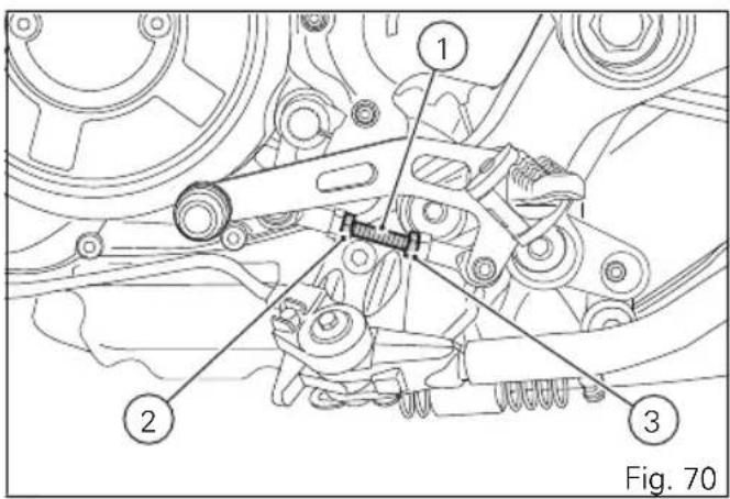
Rear brake pedal
Loosen lock nut (4).
Turn pedal stroke adjusting screw (5) until pedal is in the desired position. Tighten the lock nut (4).
Operate the pedal by hand to check that there is 1.5 to 2 mm of free play before the brake bites. If not, adjust the length of the master cylinder control rod as follows.
Loosen lock nut (6) on master cylinder rod.
Screw the rod (7) into the fork (8) to increase the free play, or screw it out to reduce it.
Tighten lock nut (6) and check play again.
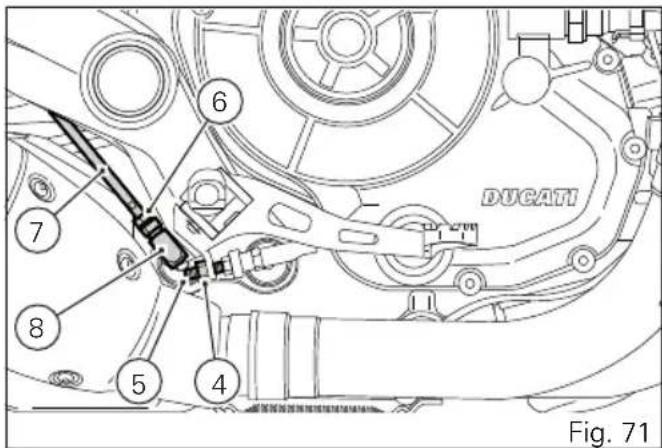
Main components and devices
Position on the vehicle
1) Tank filler plug.
2) Seat lock.
3) Side stand.
4) Rear-view mirrors.
5) Rear shock absorber adjusters.
6) Catalytic converter.
7) Exhaust silencer.
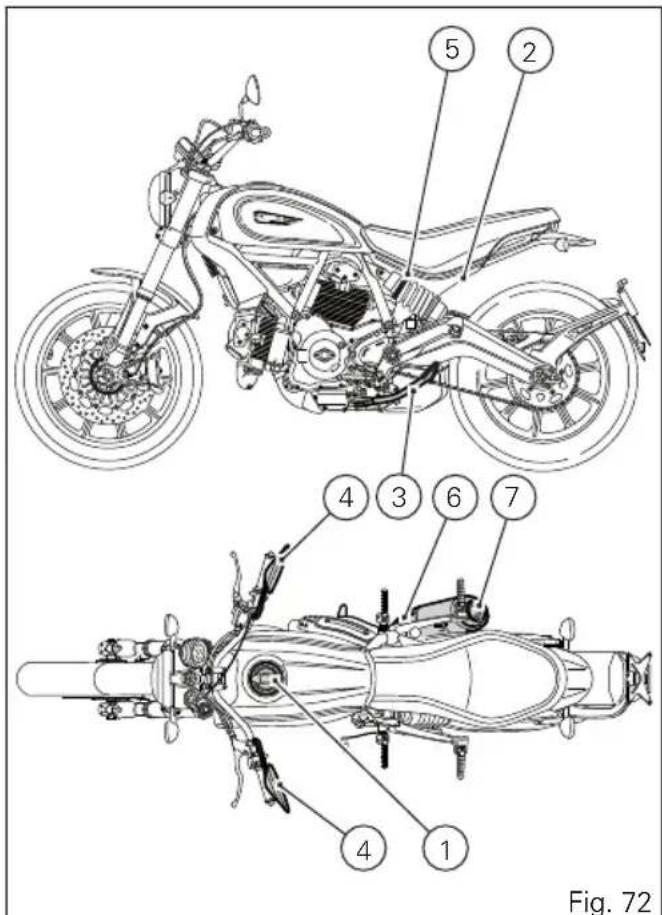
Tank filler plug
Opening
Insert the key into the lock.
Turn the key clockwise by 1/4 of a turn to release the lock.
Unscrew the plug (1).
Closing
Tighten the plug (1) with the key inserted and push it down into its seat.
Turn the key counter clockwise to the original position and remove it.

Note
Plug can only be closed when key is inserted.

Warning
After refuelling, always make sure that the plug is perfectly in place and closed.
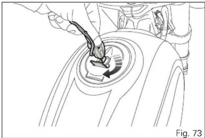
natural_image
Line drawing of a hand using a tool to press down a circular component with an arrow indicating rotation (no text or symbols)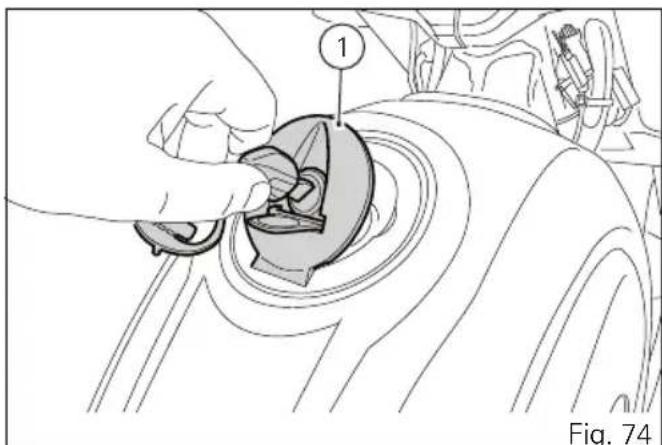
natural_image
Diagram of a hand turning a car gear into a gear shift, labeled with number 1 (no text or symbols on the diagram itself)Seat lock
Opening
Insert the key (1) in lock, turn clockwise while pressing down at the latch to help release the pin.
Remove the seat (2) pulling it backwards until sliding it out of the front retainers.
Closing
Make sure all parts are correctly laid out and secured in the underseat compartment.
Slide the front end (A) of the seat bottom underneath the retainer (B) of the frame support.
Press on seat (2) rear end until locking latch snaps.
Make sure the seat is safely secured to the frame and remove the key (1) from the lock.
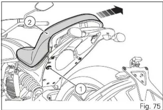
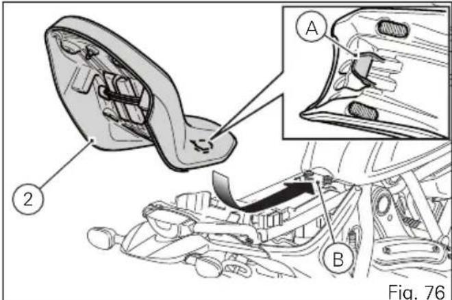
Side stand

Important
Place the motorcycle on the side stand only when you are not going to use it for short periods of time. Before lowering the side stand, make sure that the bearing surface is hard and flat.
Do not park on soft or pebbled ground or on asphalt melt by the sun heat and similar or the motorcycle may fall over. When parking in downhill road tracts, always park the motorcycle with its rear wheel facing downhill.
To pull down the side stand, hold the motorcycle handlebar with both hands and push down on the side stand (1) with your foot until it is fully extended. Tilt the motorcycle until the side stand is resting on the ground.
To move the side stand to its rest position (horizontal position), lean the motorcycle to the right while lifting the thrust arm (1) with your foot.
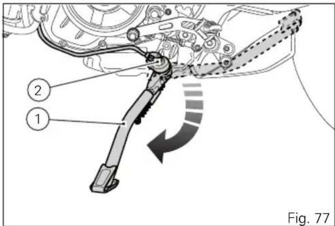

Warning
Do not sit on the motorcycle when it is supported on the side stand.

Note
Check for proper operation of the stand mechanism (two springs, one into the other) and the safety sensor (2) at regular intervals.
USB connection
The motorcycle is equipped with a USB 5V connection. Loads up to 1A can be connected to the USB connection.
USB connection (1) is located under the seat and is protected by a flap: lift flap to use connection.

Important
When the engine is off and key set to ON, do not leave accessories connected to the USB socket for a long period of time as the motorcycle battery could run flat.

Warning
The USB connection, with no protection cap, was not designed as a waterproof unit, you are thus recommended not to connect any device to the USB socket in case of rain.
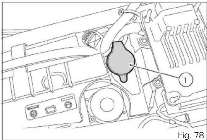
natural_image
Technical line drawing of a mechanical assembly with labeled component (no text or symbols beyond label)Adjusting the rear shock absorber
The rear shock absorber has adjusters that enable you to suit the setting to the load on the motorcycle. The ring nut (A), located in the shock absorber upper side, adjusts the external spring preload.
To change spring preload, turn the ring nut (A) using the supplied pin wrench, and align ring nut cam with the reference notch (B). Ring nut has five cams (1, 2, 3, 4 and 5) which correspond to the available preload settings: turn counter clockwise (C) to INCREASE preload, or turn clockwise (D) to DECREASE preload. Standard setting is the one for which reference notch (B) on shock absorber is aligned with ring nut third cam: position indicated in the figure.
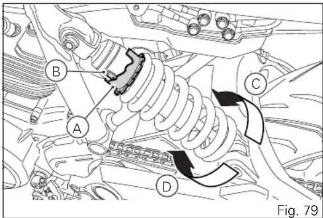
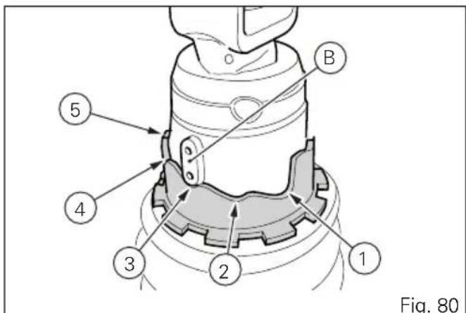

Warning
To turn the preload adjuster ring nut use the wrench supplied with the tool kit. Pay attention to avoid hand injuries by hitting motorcycle parts in case the wrench tooth suddenly slips on the ring nut cam while moving it.

Warning
The shock absorber is filled with gas under pressure and may cause severe damage if taken apart by unskilled persons.
When carrying a passenger and luggage, set the rear shock absorber spring to proper preload to improve motorcycle handling and keep safe clearance from the ground.
Riding the motorcycle
Running-in recommendations Maximum rotation speed
Rotation speed for running-in period and during standard use (rpm):
1) up to 1,000 km;
2) from 1,000 km to 2,500 km.
Up to 1,000 km
During the first 1000 km, keep an eye on the rev counter. It should never exceed: 5,500÷6,000 rpm. During the first hours of riding, it is advisable to run the engine at varying load and rpm, though still within recommended limit.
To this end, roads with plenty of bends and even slightly hilly areas are ideal for a most efficient running-in of engine, brakes and suspensions. For the first 100 km use the brakes gently. Avoid sudden or prolonged braking. This will allow the friction material on the brake pads to bed in against the brake discs.
For all mechanical parts of the motorcycle to adapt to one another and above all not to adversely affect the life of basic engine parts, it is advisable to avoid harsh accelerations and not to run the engine at high rpm for too long, especially uphill.
Furthermore, the drive chain should be inspected frequently. Lubricate as required.
From 1,000 km to 2,500 km
From 1,000 km to 2,500 km you can squeeze some more power out of your engine. However never exceed 7,000 rpm.

Important
During the whole running-in period, the maintenance and service rules recommended in the Warranty Card should be observed carefully. Failure to follow these instructions releases Ducati Motor Holding S.p.A. from any liability whatsoever for any engine damage or shorter engine life.
Strict observance of running-in recommendations will ensure longer engine life and reduce the likelihood of overhauls and tune-ups.
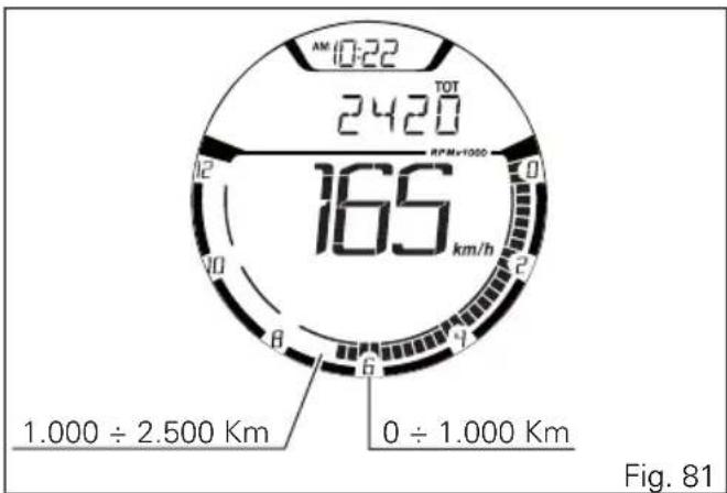
Pre-ride checks

Warning
Failure to carry out these checks before riding, may lead to motorcycle damage and injury to rider and passenger.
Before riding, perform a thorough check-up on your motorcycle as follows:
- FUEL LEVEL IN THE TANK
Check the fuel level in the tank. Fill tank if needed (page 133).
- ENGINE OIL LEVEL
Check oil level in the sump through the sight glass. Top up if needed (page 156).
- BRAKE FLUID
Check fluid level in the relevant reservoirs (page 135).
- TYRE CONDITION
Check tyre pressure and condition (page 154).
- CONTROLS
Work the brake, clutch, throttle and gear change controls (levers, pedals and twistgrip) and check for proper operation.
- LIGHTS AND INDICATORS
Make sure lights, indicators and horn work properly. Replace any burnt-out bulbs (page 90).
- KEY LOCKS
Ensure that tank filler plug (page 115) and seat (page 116) are properly locked.
- STAND
Make sure side stand operates smoothly and is in the correct position (page 117).
ABS light
After Key-ON, the ABS light stays ON.
When the motorcycle speed exceeds 5 km/h, the warning light switches OFF to indicate the correct operation of the ABS system.

Warning
In case of malfunction, do not ride the motorcycle and contact a Ducati Dealer or authorised Service Centre.
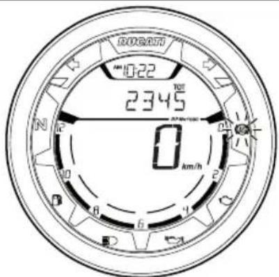
Fig. 82
ABS device
Check that the front (1) and rear (2) phonic wheels are clean.

Warning
Clogged reading slots would compromise system proper operation. It is recommended to disable ABS system in case of muddy road surface because under this condition the system might be subject to sudden failure.

Warning
Prolonged wheelies could deactivate the ABS system.
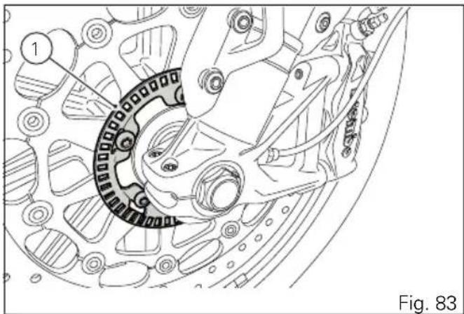
natural_image
Technical line drawing of a mechanical assembly with gear and components (no text or symbols)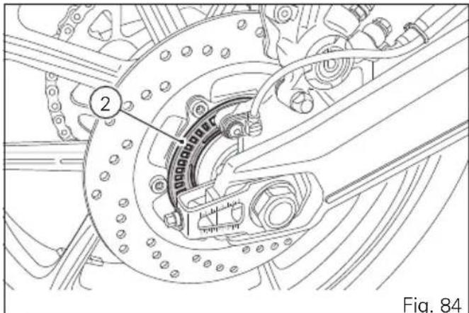
Starting the engine

Warning
Before starting the engine, become familiar
with the controls you will need to use when riding.

Warning
Never start or run the engine indoors. Exhaust gases are poisonous and may lead to loss of consciousness or even death within a short time.
Move the ignition switch to (1, Fig. 85). Make sure both the green light N and the red light 📋 on the instrument panel come on.

Important
The oil pressure light should go out a few seconds after the engine has started.
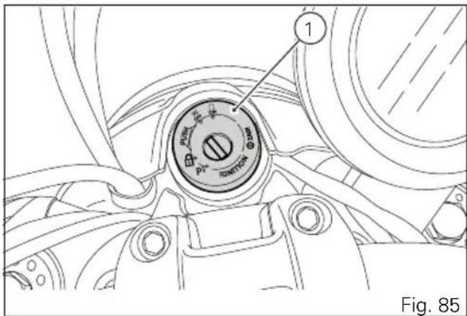
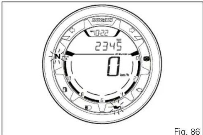

Warning
The side stand must be fully up (in a horizontal position) as its safety sensor prevents engine starting when down.

Note
It is possible to start the engine with side stand down and the gearbox in neutral. When starting the motorcycle with a gear engaged, pull the clutch lever (in this case the side stand must be up).
Check that the stop switch (2, Fig. 87) is positioned to ○ (RUN), then press the starter button (3, Fig. 87).
Let the motorcycle start without operating the throttle control.
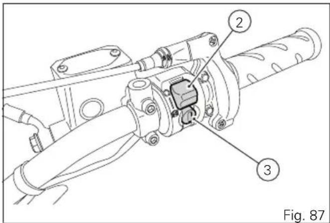

Note
If the battery is flat, system automatically inhibits starter motor cranking operation.

Important
Do not rev up the engine when it is cold. Allow some time for oil to be heated and reach all points that need lubricating.
Moving off
1) Squeeze the control lever to disengage the clutch.
2) Push down on gear change lever sharply with the tip of your foot to engage the first gear.
3) Speed up the engine by turning the throttle twistgrip while gradually releasing the clutch lever; the motorcycle will start moving off.
4) Let go of clutch lever and speed up.
5) To shift up, close the throttle to slow down engine, disengage the clutch, lift the gear change lever and let go of clutch lever.
To shift down, proceed as follows: release the twistgrip, pull the clutch lever, shortly speed up to help gears synchronise, shift down (engage next lower gear) and release the clutch.
The controls should be used correctly and timely: when riding uphill do not hesitate to shift down as soon as the motorcycle tends to slow down, so you will avoid stressing the engine and the motorcycle abnormally.
Warning
Avoid harsh acceleration, as this may lead to misfiring and transmission snatching. The clutch lever should not be held in longer than necessary after a gear is engaged, otherwise friction parts may overheat and wear out.
Warning
Prolonged wheelies could deactivate the ABS system.
Braking
Slow down in time, shift down to use engine brake and then brake by operating both front and rear brakes. Pull the clutch before the motorcycle stops to avoid engine from suddenly stalling.
Anti-Lock Braking System (ABS)
Using the brakes correctly under adverse conditions is the hardest – and yet the most critical - skill to master for a rider. Braking is one of the most difficult and dangerous moments when riding a two wheeled motorcycle: the possibility of falling or having an accident during this difficult moment is statistically higher than any other moment. A locked front wheel leads to loss of traction and stability, resulting in loss of control.
The Anti-Lock Braking System (ABS) has been developed to enable riders to use the motorcycle braking force to the fullest possible amount in emergency braking or under poor pavement or adverse weather conditions.
ABS uses hydraulics and electronics to limit pressure in the brake circuit when a special sensor mounted to the wheel informs the electronic control unit that the wheel is about to lock up.
This avoids wheel lockup and preserves traction.
Pressure is raised back up immediately and the control unit keeps controlling the brake until the risk of a lockup disappears.
Normally, the rider will perceive ABS operation as a harder feel or a pulsation of the brake lever and pedal. The front and rear brakes use separate control systems, meaning that they operate independently. Likewise, the ABS is not an integral braking system and does not control both the front and rear brake at the same time.
If desired, the system can be deactivated from the instrument panel, using the "ABS control unit enabling/disabling" function (seepage 64).

Warning
When ABS is disabled, the motorcycle restores the standard brake system features; using the two brake controls separately reduces the motorcycle braking efficiency. Never use the brake controls harshly or suddenly as you may lock the wheels and lose control of the motorcycle. When riding in the rain or on slippery surfaces, braking will become less effective. Always use the brakes very gently and carefully when riding under these conditions. Any sudden manoeuvres may lead to loss of control. When tackling long, high-gradient downhill road tracts, shift down gears to use engine braking. Apply one brake at a time and use brakes sparingly. Keeping the brakes applied all the time would cause the friction material to overheat and reduce braking power dangerously. Underinflated tyres reduce braking efficiency, handling accuracy and stability in a bend.
Stopping the motorcycle
Reduce speed, shift down and release the throttle twistgrip.
Shift down to engage first gear and then neutral.
Apply the brakes and bring the motorcycle to a complete stop.
To switch the engine off, simply turn the key to position (2).

Important
Do not leave the key to ON, position (1), with engine off in order to avoid damaging any electrical components.
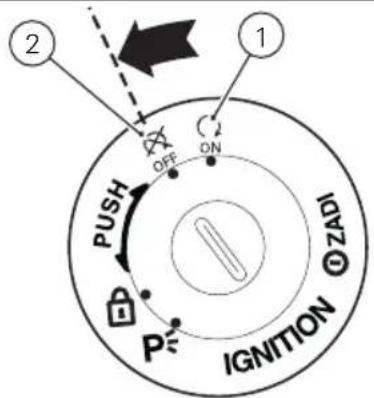
Fig. 88
Parking
Stop the motorcycle, then put it on the side stand. To prevent theft, turn the handlebar fully left and turn the ignition key to position (3). If you park in a garage or other indoor area, make sure that there is proper ventilation and that the motorcycle is not near a source of heat. If required, turn the key to position (4) to leave the parking lights on.

Important
Do not leave the key to position (4) for a long time, or this could lead to battery discharge. Never leave the ignition key in the switch when you are leaving your motorcycle unattended.

Warning
The exhaust system might be hot, even after engine is switched OFF; pay particular attention not to touch the exhaust system with any body part and do not park the motorcycle next to inflammable material (wood, leaves etc.).
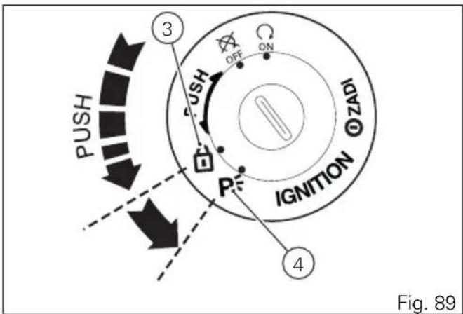

Warning
Using padlocks or other locks designed to prevent motorcycle motion, such as brake disc locks, rear sprocket locks, and so on is dangerous and may impair motorcycle operation and affect the safety of rider and passenger.
Refuelling
Never overfill the tank when refuelling. Fuel should never be touching the rim of filler recess (1).

Warning
Use fuel with low lead content and an original octane number of at least 95.

Warning
The motorcycle is only compatible with fuel having a maximum content of ethanol of 10% (E10). Using fuel with ethanol content over 10% is forbidden. Using it could result in severe damage of the engine and motorcycle components. Using fuel with ethanol content over 10% will make the warranty null and void.
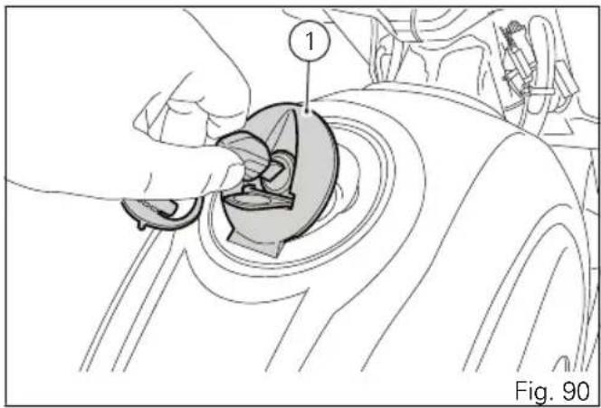
natural_image
Diagram of a hand using a tool to adjust or install a mechanical component, labeled with number 1 (no text or symbols on the diagram itself)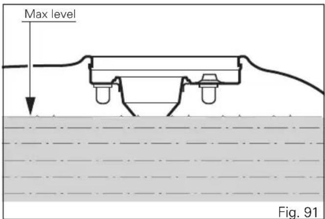
Tool kit and accessories
The tool box (1) is located under the seat.
The tool box includes:
- screwdriver;
- screwdriver handgrip;
- 3 mm Allen wrench;
- 4 mm Allen wrench;
- preload adjustment wrench;
- handgrip for preload adjustment wrench.
To access the compartment remove the seat page 116.
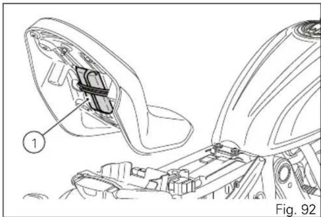
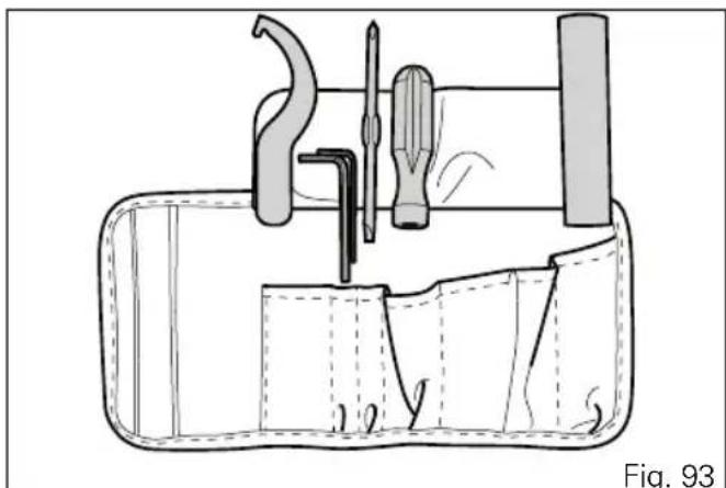
natural_image
Technical line drawing of a mechanical assembly with tools and components, no visible text or symbolsMain maintenance operations
Check brake fluid level
The level must not go below the MIN mark shown on the respective reservoirs ((Fig. 94) shows the front brake fluid reservoir, while (Fig. 95) shows the rear brake fluid reservoir).
If level drops below the limit, air might get into the circuit and affect the operation of the system involved.
Fluid must be topped up and changed at the intervals specified in the scheduled maintenance table reported in the Warranty Booklet; please contact a Ducati Dealer or authorised Service Centre.

Important
It is recommended all lines be changed every four years.
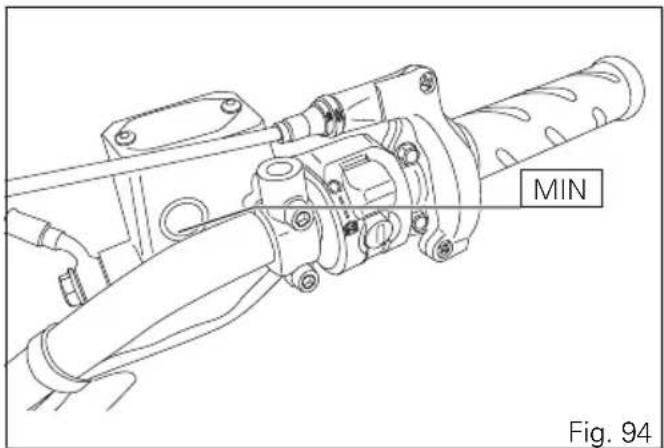
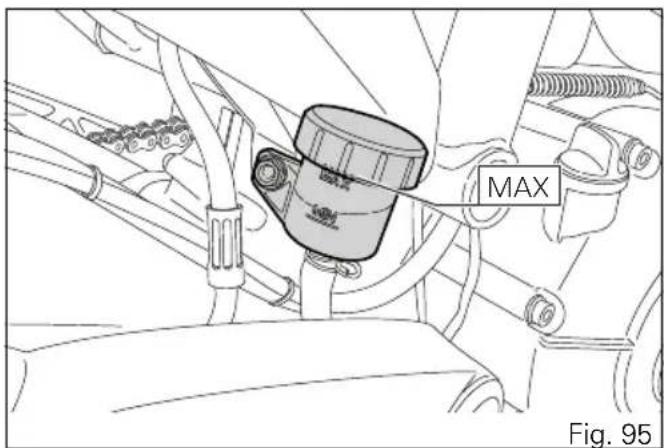
Brake system
If you find exceeding clearance on brake lever or pedal and brake pads are still in good condition, contact your Ducati Dealer or authorised Service Centre to have the system inspected and any air drained out of the circuit.

Warning
Brake fluid can damage paintwork and plastic
parts, so avoid contact.
Hydraulic fluid is corrosive; it may cause damage and lead to severe injuries. Never mix fluids of different qualities. Check seals for proper sealing.
Changing the air filter

Important
Have the air filter maintenance performed at a
Ducati Dealer or Authorised Service Centre.
Checking brake pads for wear
Check brake pads wear through the inspection hole in the callipers.
Change both pads if friction material thickness of even just one pad is about 1 mm.

Warning
Friction material wear beyond this limit would lead to metal support contact with the brake disc thus compromising braking efficiency, disc integrity and rider safety.

Important
Have the brake pads replaced at a Ducati Dealer or authorised Service Centre.
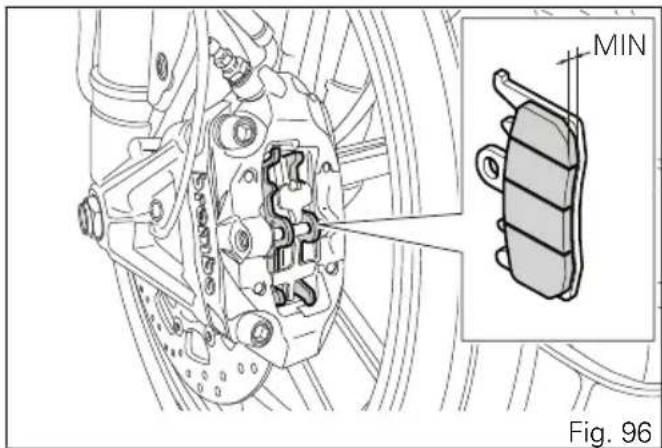
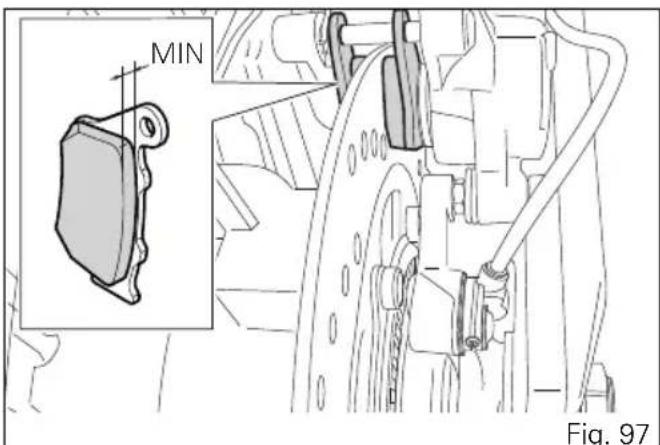
Charging the battery

Warning
Have the battery removed at a Ducati Dealer or authorised Service Centre.
To reach the battery, remove the seat page 116 and remove battery cover (A), after disengaging rubber band (C) and loosening screw (D). Loosen the screws (1), remove the positive cable (2) and (ABS) positive cable (3) from the positive terminal and the negative cable (4) from the negative terminal always starting from the negative one (-) and remove the battery by sliding it out of its housing.

Warning
The battery gives off explosive gases; never cause sparks or allow naked flames and cigarettes near the battery. When charging the battery, ensure that the working area is properly ventilated.
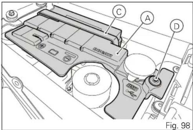
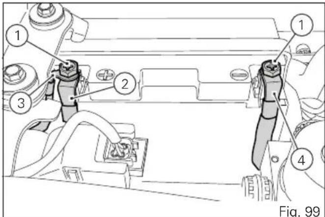
Charge the battery in a ventilated room. Connect the battery charger leads to the battery terminals: the red one to the positive terminal (+), the black one to the negative terminal (-).

Important
Make sure the charger is OFF when you
connect the battery to it, or you might get sparks at the battery terminals that could ignite the gases inside the cells. Always connect the red positive (+) terminal first.
Grease the screws (1, Fig. 99).
Refit the battery, connect the positive cable (2, Fig. 99) and ABS positive cable (3, Fig. 99) to the positive terminal, and the negative cable (4, Fig. 99) to the negative terminal of the battery, always starting from the positive one (+), and start the screws (1, Fig. 99). Refit the battery cover (A, Fig. 98), engage rubber band (C, Fig. 98) and tighten screw (D, Fig. 98) to 5 Nm ± 10%.

Warning
Keep the battery out of the reach of children.
Charge the battery at 0.9 A for 5÷10 hours.
If the motorcycle must be jump-started in an emergency with an external starting device, it is possible to connect the starting device to the battery without removing it from the vehicle. Connect the external starting device positive pole to the battery positive pole and the external starting device negative pole to the battery negative pole.

Warning
When connecting the external starting device to the poles of the vehicle battery, pay utmost attention not to touch any other metal parts on the vehicle.
Charging and maintenance of the battery during winter storage
Your motorcycle is equipped with a connector (1), located under the seat, to which you can connect a special battery charger (2) (Battery maintenance kit part no. 69924601A - various countries; Battery maintainer kit part no. 69924601AX - for Japan, China and Australia only) available from our sales network.

Note
The electric system of this model is designed so as to ensure there is a very low power drain when the motorcycle is OFF. Nevertheless, the battery features a certain self-discharge rate that is normal and depends on ambient conditions as well as on "non-use" time.
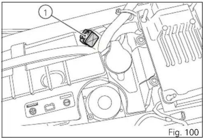
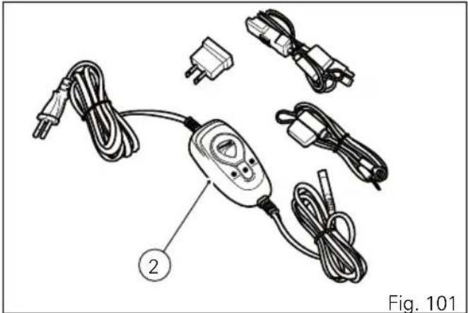
natural_image
Diagram of a handheld electronic device with wires and connectors, labeled as Fig. 101 (no text or symbols on the device itself)
Important
If battery is not kept at a minimum charge level by a suitable battery charge maintainer, sulphation may occur and this is an irreversible phenomenon causing decreasing battery performance.

Note
When the motorcycle is left unused (approximately for more than 30 days) we recommend owners to use the Ducati battery charge maintainer (Battery maintenance kit part no. 69924601A - various countries; Battery maintainer kit part no. 69924601AX - for Japan, China and Australia only) since its electronics monitors the battery voltage and features a maximum charge current of 1.5 Ah. Connect the maintainer to the diagnostics socket located in the rear side of the motorcycle.

Note
Using charge maintainers not approved by Ducati could damage the electric system; motorcycle warranty does not cover the battery if damaged due to failure to comply with the above indications, since it is considered as wrong maintenance.
Lubricating cables and joints
It is necessary to periodically check the throttle control cable and cold start cable external sheath for wear. Their external plastic sheath should be free of cracking or flattening. Work the controls to make sure the cable slides smoothly inside the sheath: if you feel any friction or catching, have the cable replaced by a Ducati Dealer or Authorised Service Centre. For trouble-free operation, periodically lubricate the ends of all Bowden cables with SHELL Advance Grease or Retinax LX2.
As far as the throttle cable is concerned, it is recommended to undo the two screws (1) and open the control, then grease the cable end and the pulley.

Warning
Carefully close the control after engaging the cable in the pulley.
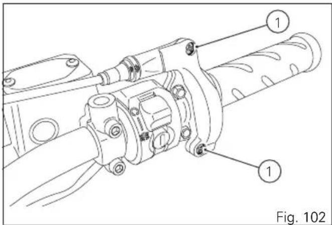
Refit the cover and tighten the screws (1) to a torque of 1.8 Nm.
To ensure trouble-free operation of the side stand joint, thoroughly clean it and then use SHELL Alvania R3 grease to lubricate all friction points.
Adjusting the throttle cable
The throttle grip must have a free play of 2 to 4 mm in all steering positions, measured on the outer edge of the twistgrip; this value is indicated in the figure as reference (A).
To adjust, work the relevant adjuster (1) located on the control itself.
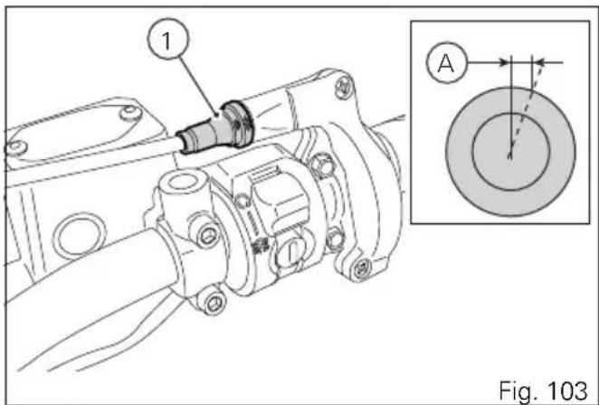
Checking drive chain tension

Important
Have chain tension adjusted by a Ducati Dealer or authorised Service Centre.
Make the rear wheel turn until you find the position where chain is tightest. Set the motorcycle on the side stand. With just a finger, push down the chain at the point of measurement and release. Measure the distance (A) between the centre of the chain pins and the aluminium section of the swinging arm. It must be: A = 27 ÷ 29 mm.

Important
If drive chain is too tight or slack, adjust tension so as to bring values back to the specified range.
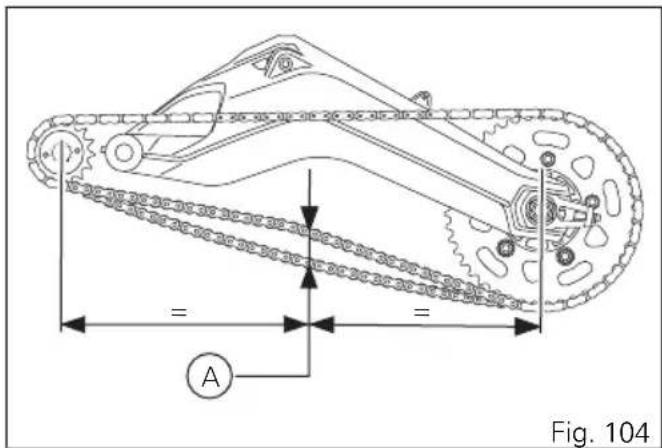

Warning
Correct tightening of swinging arm screws (1) is critical to rider and passenger safety.

Important
Improper chain tension will lead to early wear of transmission parts.
Check the correspondence of the positioning marks on both sides of the swinging arm to ensure a perfect wheel alignment. Grease the wheel shaft nut thread (2) with SHELL Retinax HDX2 and tighten it to a torque of 145 Nm. Grease the adjuster screws (1) thread with SHELL Alvania R3 and tighten them to a torque of 10 Nm.
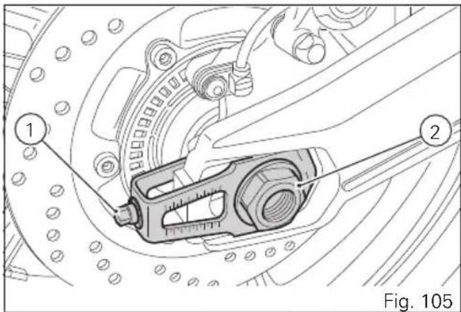
Lubricating the drive chain
The chain fitted on your motorcycle has O-rings that keep dirt out of and lubricant inside the sliding parts. The seals might be irreparably damaged if the chain is cleaned using any solvent other than those specific for O-ring chains or washed using steam or water cleaners.
After cleaning, blow the chain dry with compressed air or wipe it with an absorbent material, then lubricate each link with SHELL Advance Chain or Advance Teflon Chain.

Important
Using non-specific lubricants may cause severe damage to the chain and the front and rear sprockets.
Replacing the headlight bulbs

Important
Have the lights replaced by a Ducati Dealer or an Authorised Service Centre.

Warning
The headlight might fog up if the motorcycle is used under the rain or after washing. Switch headlight on for a short time to dry up any condensate.
Before replacing a burnt-out bulb, make sure that the new one matches the voltage and wattage specifications in paragraph "Electric System" page 178. Always ensure that the new bulb you have installed operates properly before refitting any parts you have removed.
Loosen screws (1) and collect headlight support U-bolts (2).
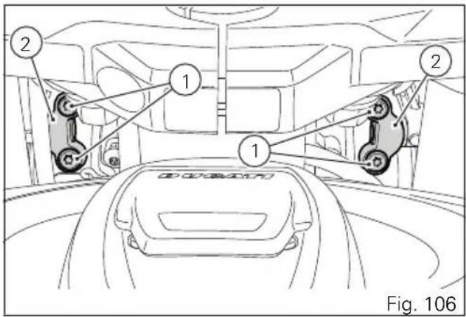
Loosen screw (3).
Tilt headlight towards the front mudguard and duly support it while loosening screws (4) on light cover (5) and remove cover.
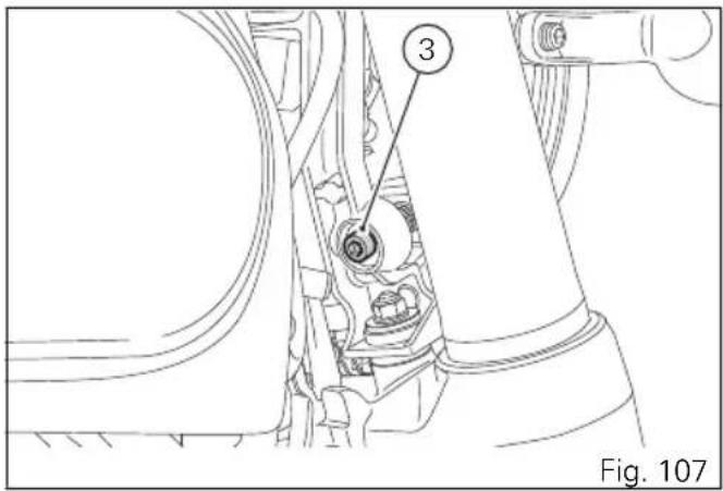
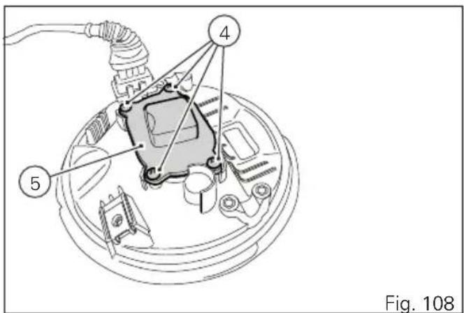
Disconnect the connector (6).
Release the clip (7).
The bulb (8) has a bayonet joint: press and twist counter clockwise to remove it. Remove the bulb, then fit the new one by pressing and turning clockwise until it clicks into its seat.

Note
Be careful to hold the new bulb at the base only.
Never touch the transparent body with your fingers or it will blacken resulting in reduced bulb brilliancy.
To reassemble, refit any previously removed parts following the removal procedure in reverse order and tighten screws (1, Fig. 106) to 5 Nm.
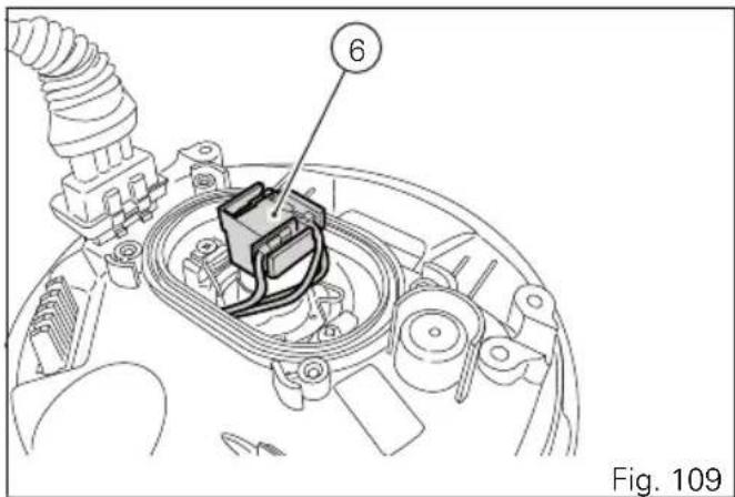
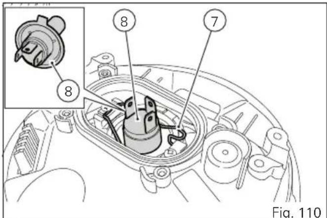
Changing the turn indicator bulbs To change the front/rear turn indicator bulbs, loosen the screw (1) and remove the lens (2).
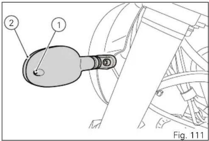
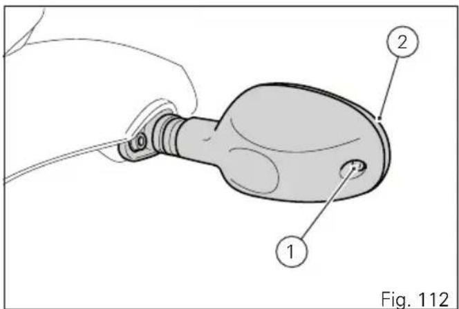
Aligning the headlight

Note
Headlight features two adjusters, one for the RH beam and one for the LH beam.
Check correct headlight aiming. Position the motorcycle 10 metres from a wall or a screen, the motorcycle must be perfectly upright with the tires inflated to the correct pressure and with a rider seated, perfectly perpendicular to the longitudinal axis. On the wall or surface, draw a horizontal line at the same height from the ground as the centre of the headlight and a vertical line aligned with the longitudinal axis of the motorcycle. If possible, perform this check in dim light. Switch on the low beam and adjust right and left beams. The height of the upper limit between the dark area and the lit area must not be more than 9/10 of the height from the ground of the headlight centre.
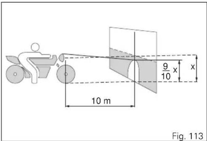

Note
This is the procedure specified by Italian regulations for checking the maximum height of the light beam. Please adapt said procedure to the provisions in force in your own country.
Aligning the headlight
The vertical alignment of the headlight can be manually set by turning screw (1).

Important
Headlight beam adjuster screw has no limit stop.

Warning
The headlight might fog up if the motorcycle is used under the rain or after washing. Switch headlight on for a short time to dry up any condensate.
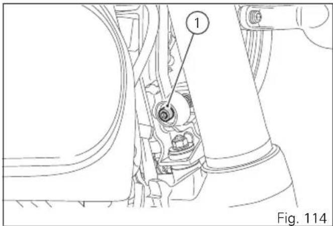
Adjusting the rear-view mirrors Manually adjust rear-view mirror (A) to required position.
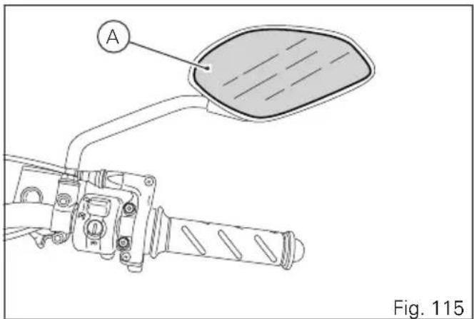
Tubeless tyres
Front tyre pressure:
2.50 bar (rider only) - 2.50 bar (full load).
Rear tyre pressure:
2.50 bar (rider only) - 2.90 bar (full load).
As tyre pressure is affected by ambient temperature and altitude variations, you are advised to check and adjust it whenever you are riding in areas where ample variations in temperature or altitude occur.

Important
Check and set tyre pressure when tyres are cold. To avoid front wheel rim distortion, when riding on bumpy roads, increase tyre pressure by 0.2 ÷ 0.3 bar.
Tyre repair or change (Tubeless tyres)
In the event of a tiny puncture, tubeless tyres will take a long time to deflate, as they tend to keep air inside. If you find low pressure on one tyre, check the tyre for punctures.
Warning Punctured
Punctured tyres must be replaced. Replace tyres with recommended standard tyres only. Be sure to tighten the valve caps securely to avoid leaks when riding. Never use tube type tyres. Failure to heed this warning may lead to sudden tyre bursting and to serious danger to rider and passenger.
After replacing a tyre, the wheel must be balanced.
Warning Do not rem
Do not remove or shift the wheel balancing weights.
Note Have t
Have the tyres replaced at a Ducati Dealer or authorised Service Centre. Correct removal and installation of the wheels is essential. Some parts of the ABS (such as sensors and phonic wheels) are mounted to the wheels and require specific adjustment.
Minimum tread depth
Measure tread depth (S, Fig. 116) at the point where tread is most worn down: it should not be less than 2 mm, and in any case not less than the legal limit.

Important
Visually inspect the tyres at regular intervals for detecting cracks and cuts, especially on the side walls, bulges or large spots that are indicative of internal damage. Replace them if badly damaged. Remove any stones or other foreign bodies caught in the tread.
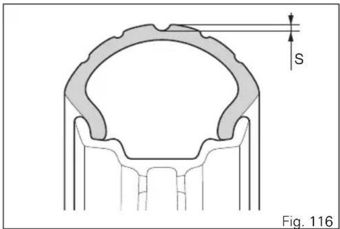
Check engine oil level
Engine oil level can be checked through the sight glass (1) located onto clutch cover. Oil level must be checked with the motorcycle perfectly upright and the engine cold. Oil level should be between the marks on the sight glass. If the level is low, top up with SHELL Advance 4T Ultra engine oil. Remove the oil filler cap (2) and top up until the oil reaches the required level. Refit the plug.

Important
Engine oil and oil filters must be changed by a Ducati Dealer or authorised Service Centre at the intervals specified in the scheduled maintenance chart reported in the Warranty Card.
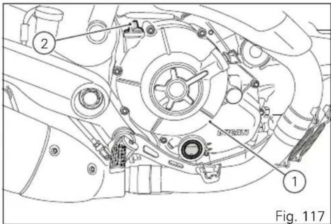
Viscosity
SAE 15W-50
The other viscosity degrees indicated in the table can be used if the local average temperature is within the limits specified for that oil viscosity.
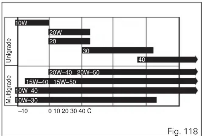
bar
| Category | Value | |---|---| | Unigrade 10W | -5 | | Unigrade 20W | 40 | | Unigrade 20 | 30 | | Multigrade 15W-40 | -8 | | Multigrade 15W-50 | -8 | | Multigrade 10W-40 | -8 | | Multigrade 10W-30 | -7 |Cleaning and replacing the spark plugs
Spark plugs are essential to smooth engine running and should be checked at regular intervals.
Have the spark plug replaced by a Ducati Dealer or an authorised Service Centre.
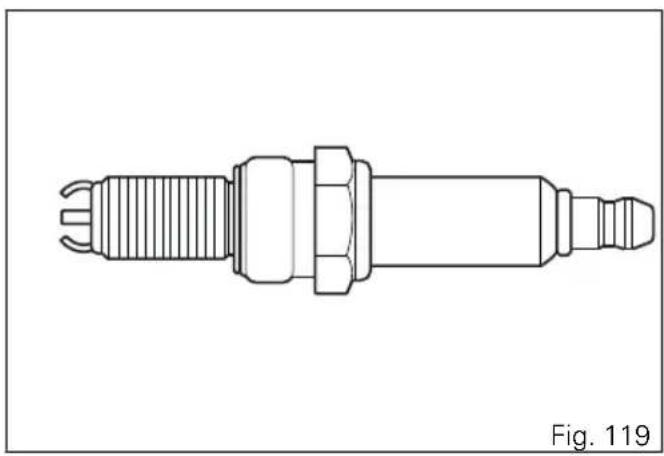
natural_image
Technical line drawing of a mechanical component (no text or symbols)Cleaning the motorcycle
To preserve the finish of metal parts and paintwork, wash and clean your motorcycle at regular intervals, anyway according to road conditions. Use specific products only. Prefer biodegradable products. Avoid aggressive detergents or solvents.
Use only water and neutral soap to clean the Plexiglas and the seat.
Periodically clean by hand all aluminium components. Use special detergents, suitable for aluminium parts. Do NOT use abrasive detergents or caustic soda.

Note
Do not use sponges with abrasive parts or steel wool: only use soft cloths.
However, the warranty does not apply to motorcycles whenever poor maintenance status is ascertained.

Important
Do not wash your motorcycle right after use.
When the motorcycle is still hot, water drops will evaporate faster and spot hot surfaces.
Never clean the motorcycle using hot or high-pressure water jets.
Cleaning the motorcycle with a high pressure water jet may lead to seizure or serious faults in forks, wheel hubs, electric system, headlight (fogging), fork seals, air inlets or exhaust silencers, with consequent loss of compliance with the safety requirements.
Clean off stubborn dirt or exceeding grease from engine parts using a degreasing agent. Be sure to avoid contact with drive parts (chain, sprockets, etc.).
Rinse with warm water and dry all surfaces with chamois leather.

Warning
Braking performance may be impaired
immediately after washing the motorcycle. Never grease or lubricate the brake discs to avoid losing braking power. Clean the discs with an oil-free solvent.

Warning
The headlight might fog up due to washing, rain or moisture. Switch headlight on for a short time to help and dry up any condensate.
Carefully clean the phonic wheels of the ABS in order to ensure system efficiency. Do not use aggressive products in order to avoid damaging the phonic wheels and the sensors.
Storing the motorcycle
If the motorcycle is to be left unridden over long periods, it is advisable to carry out the following operations before storing it away:
- clean the motorcycle;
- empty the fuel tank;
- pour a few drops of engine oil into the cylinders through the spark plug seats, then crank the engine by hand a few times so a protective film of oil will spread on cylinder inner walls;
- place the motorcycle on a service stand;
- disconnect and remove the battery.
Battery should be checked and charged (or replaced, as required) whenever the motorcycle has been left unridden for over a month.
Protect the motorcycle with a suitable canvas. This will protect paintwork and let condensate breathe out.
The canvas is available from Ducati Performance.
Important notes
Some countries, such as France, Germany, Great Britain, Switzerland, etc. have compulsory emission and noise standards that include mandatory inspections at regular intervals.
Periodically carry out the required checks and renew parts as necessary, using Ducati original spare parts, in compliance with the regulations in the country concerned.
Scheduled maintenance chart
Scheduled maintenance chart: operations to be carried out by the dealer
| List of operations and type of intervention [set mileage (km/mi) or time interval *] | km. x1,000 mi. x1,000 | 1 12 | 24 36 | 48 | Time (months) | ||
| 0.6 7 | .5 15 2 | 22.5 30 | |||||
| Reading of the error memory with DDS and check of software version update on control units | ● | ● | 12 | ● | ● | ||
| Check the presence of any technical updates and recall campaigns | ● | ● | 12 | ● | ● | ||
| Change engine oil and filter | 12 | ● | ● | ● | ● | ● | |
| Clean the engine oil mesh filter assembly | - | ● | |||||
| Check and/or adjust valve clearance | - | ● | ● | ● | ● | ||
| Change timing belts | ● | ● | 60 | ||||
| Change spark plugs | ● | ● | - | ||||
| Clean air filter | ● | ● | - | ||||
| Change air filter | ● | ● | - | ||||
| Check brake fluid level | ● | ● | 12 | ● | ● | ||
| Change brake fluid | 36 | ||||||
| Check brake disc and pad wear. Change, if necessary | ● | ●12 | ● | ● | ● | ||
| Check the proper tightening of brake calliper bolts and brake disc flange screws | ● | ● | 12 | ● | ● | ||
| Check front and rear wheel nuts tightening | 12 | ● | ● | ● | ● | ||
| Check frame-to-engine fasteners tightening | ● | ● | ● | ● | |||
| Check wheel hub bearings | ● | ● | |||||
| Check and lubricate the rear wheel shaft | - | ● | ● | ||||
| Check the cush drive damper on rear sprocket | - | ● | ● | ||||
| Check the proper tightening of final drive front and rear sprocket nuts | ● | ● | 12 | ● | ● | ||
| Check final drive (chain, front and rear sprocket) and sliding shoe wear | ● | 12 | ● | ● | |||
| Check final drive chain tension and lubrication | ● | ● | 12 | ● | ● | ||
| Check steering bearings and lubricate, if necessary | - | ● | ● | ||||
| Change front fork fluid | ● | - | |||||
| Visually check the front fork and rear shock absorber seals | ● | ● | 12 | ● | ● | ||
| Check the freedom of movement and tightening of the side and central stand (if any) | ● | ● | 12 | ● | ● | ||
| Visually check the fuel lines 12 | ● | ● | ● | ● | |||
| Check rubbing points, clearance, freedom of movement and positioning of hoses and electric wiring in view | ● | ● | 12 | ● | ● | ||
| Lubricate the levers at the handlebar and pedal controls | ● 12 | ● | ● | ● | |||
| Check tyre pressure and wear 12 | ● | ● | ● | ● | ● | ||
| Check the battery charge level 12 | ● | ● | ● | ● | ● | ||
| Check secondary air system operation - | ● | ● | ● | ● | |||
| Check the operation of the safety electrical devices (side stand sensor, front and rear brake switches, engine stop switch, gear/neutral sensor) | ● | ● | 12 | ● | ● | ||
| Check lighting, turn indicators, horn and controls | ● 12 | ● | ● | ● | ● | ||
| Reset the Service indication through the DDS | ● | ● | ● | ● | ● | ||
| Final test and road test of the motorcycle, testing safety devices (ex. ABS) and idling | ● | ● | 12 | ● | ● | ||
| Softly clean the motorcycle | ● | ● | 12 | ● | ● | ||
| Fill out that the service was performed in on-board documentation (Service Booklet) | ● | ● | 12 | ● | ● | ||
| List of operations and type of intervention [set mileage (km/mi) or time interval *] | km. x1,000 | 1 12 | 24 36 | 48 | Time (months) | ||
| mi. x1,000 | 0.6 7 | .5 15 2 | 2.5 30 | ||||
| Check spoked wheels as specified in the workshop manual | ● | ● | - ● | ● | ● | ||
* Service operation to be carried out in accordance with the specified distance or time intervals (km, miles or months), whichever occurs first
Scheduled maintenance chart: operations to be carried out by the Customer
| List of operations and type of intervention [set mileage (km/mi) or time interval *] | km. x1,000 | 1 |
| mi x1,000 | 0.6 | |
| Months | 6 | |
| Check engine oil level | ● | |
| Check brake fluid level | ● | |
| Check tyre pressure and wear | ● | |
| Check final drive chain tension and lubrication | ● | |
| Check brake pads. If necessary, contact your dealer to replace pads | ● |
* Service operation to be carried out in accordance with the specified distance or time intervals (km, miles or months), whichever occurs first
Technical data
Weights
Overall weight (in running order with 90% of fuel - 93/93/EC):
186 kg (ICON);
192 kg (URBAN ENDURO);
186 kg (FULL THROTTLE);
186,5 kg (CLASSIC);
Overall weight (without fluids and battery):
170 kg (ICON);
176 kg (URBAN ENDURO);
170 kg (FULL THROTTLE);
176,5 kg (CLASSIC);
Maximum allowed weight (carrying full load):
365 kg

Warning
Failure to observe weight limits could result in
poor handling and impair the performance of your motorcycle, and you may lose control of the motorcycle.
Dimensions
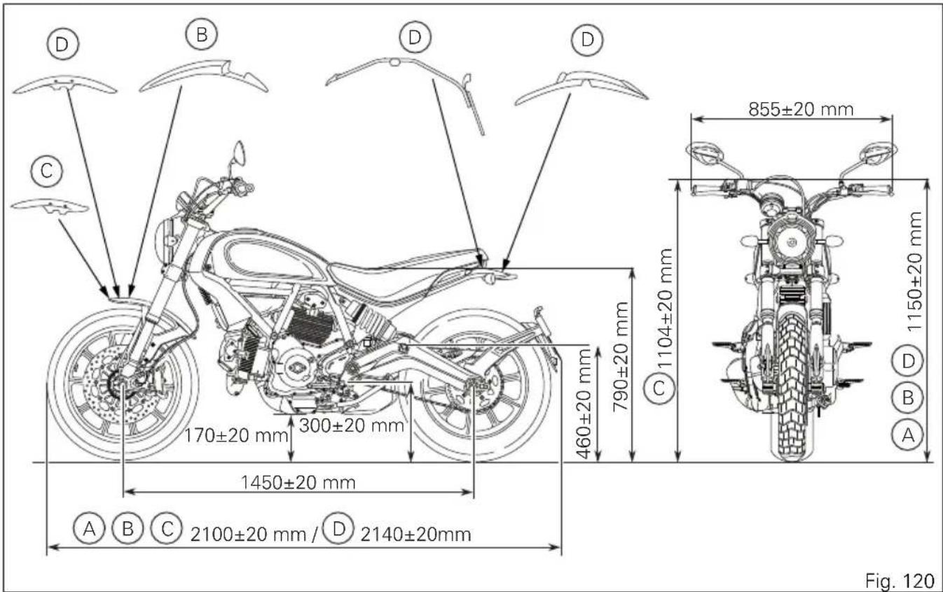
Whenever values are indicated with a letter, please refer to the following list:
A) Scrambler ICON
B) Scrambler URBAN ENDURO
C) Scrambler FULL THROTTLE
D) Scrambler CLASSIC
Fuel, lubricants and other fluids
| FUEL, LUBRICANTS AND OTHER TYPE FLUIDS | |
| Fuel tank, including a reserve of 4 cu. dm (litres) | Unleaded fuel with a minimum octane rat- 13.5 cu. dm (litres) ing of RON 95. |
| Oil sump and filter SHELL - Advance 4T Ultra | 3.4 cu. dm (litres) |
| Front/rear brake and clutch circuits SHELL Advance Brake DOT 4 - | |
| Protectant for electric contacts SHELL Advance Contact Cleaner - | |
| Front fork SHELL Advance Fork 7.5 or Donax TA | 427 cu. cm (right leg)298 cu. cm (left leg) |

Important
Do not use any additives in fuel or lubricants. Using them could result in severe damage of the engine and motorcycle components.

Warning
The motorcycle is only compatible with fuel having a maximum content of ethanol of 10% (E10). Using fuel with ethanol content over 10% is forbidden. Using it could result in severe damage of the engine and motorcycle components. Using fuel with ethanol content over 10% will make the warranty null and void.
Engine
Longitudinal 90° "L" twin cylinder, four-stroke.
Bore, mm: 88
Stroke, mm: 66
Total displacement, cu. cm: 803
Compression ratio: 11±0.5:1
Max. power at crankshaft (95/1/EC):
55 kW - 74 HP at 8,250 rpm
Max. torque at crankshaft (95/1/EC):
68 Nm - 6.9 Kgm at 5,750 rpm.
Maximum rpm:
9,200.

Important
Do not exceed the specified rpm limits in any
running conditions.
Timing system
DESMODROMIC system with two valves per cylinder controlled by four rocker arms (two opening and two closing ones) and one overhead camshaft.
This system is driven by the crankshaft through spur gears, belt rollers and toothed belts.
Desmodromic timing system
1) Opening (or upper) rocker arm;
2) Upper rocker arm shim;
3) Split rings;
4) Closing (or lower) rocker arm shim;
5) Return spring for lower rocker arm;
6) Closing (or lower) rocker arm;
7) Camshaft;
8) Valve.
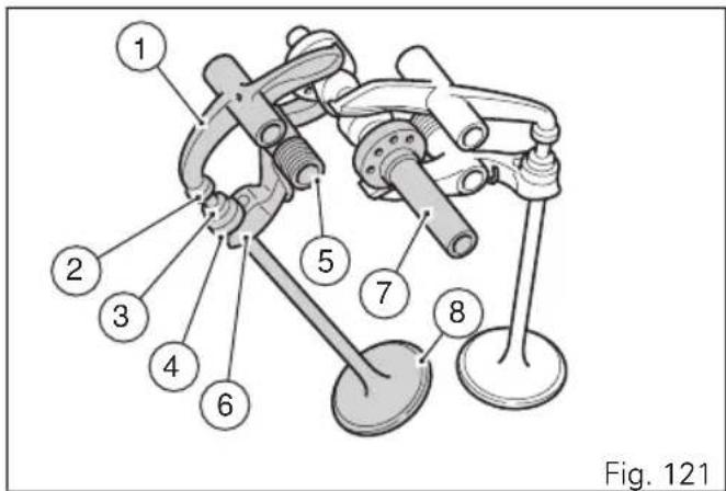
Performance data
Maximum speed in any gear should be reached only after a correct running-in period with the motorcycle properly serviced at the recommended intervals.

Important
Failure to follow these instructions releases
Ducati Motor Holding S.p.A. from any liability whatsoever for any engine damage or shorter engine life.
Spark plugs
Make: NGK
Type: DCPR8E
Fuel system
SIEMENS indirect electronic injection.
Injectors per cylinder: 1
Firing points per injector: 8
Fuel supply: 95-98 RON.

Warning
The motorcycle is only compatible with fuel
having a maximum content of ethanol of 10% (E10).
Using fuel with ethanol content over 10% is forbidden. Using it could result in severe damage of the engine and motorcycle components. Using fuel with ethanol content over 10% will make the warranty null and void.
Brakes
Separate-action anti-lock braking system operated by hall-type sensors mounted to each wheel with phonic wheel detection: ABS can be disabled.
FRONT
Semi-floating drilled disc.
Braking material: steel.
Carrier material: steel.
Disc diameter: 330 mm.
Hydraulically operated by a control lever on handlebar right-hand side.
Brake calliper make: BREMBO.
Type: M4.3 pistons.
Friction material: TT 2182 FF.
Master cylinder type: PS 13/22.
REAR
With fixed drilled steel disc.
Disc diameter: 245 mm.
Hydraulically operated by a pedal on RH side.
Make: BREMBO
Type: PF32.
Friction material: FERIT I/D 450 FF.
Master cylinder type: PS 11.

Warning
The brake fluid used in the brake system is corrosive.
In the event of accidental contact with eyes or skin, wash the affected area with abundant running water.
Transmission
Wet clutch controlled by the lever on left-hand side of the handlebar.
Drive is transmitted from engine to gearbox primary shaft via spur gears.
Front chain sprocket/clutch gearwheel ratio: 33/61
6-speed gearbox with constant mesh gears and gear change pedal on left side of motorcycle.
Gearbox output sprocket/rear chain sprocket ratio: 15/39
Total gear ratios:
1^st gear 13/32
2^nd gear 18/30
3^rd gear 21/28
4 ^th gear 23/26
5^th gear 22/22
6 ^th gear 26/24
Drive chain from gearbox to rear wheel.
Make: DID
Type: 520 VF
Size: 5/8" × 1/4"
Links: 104

Important
The above gear ratios are the homologated ones and under no circumstances must they be modified.

Warning
If the rear sprocket needs replacing, contact a Ducati Dealer or authorised Service Centre. If improperly replaced, this component could seriously endanger your safety, as well as the passenger one, and cause irreparable damage to your motorcycle.
Frame
High-strength tubular steel trellis frame.
Steering angle (per side): 35°
Steering head angle: 24°
Trail in mm: 112
Wheels
Ten-spoke light alloy wheel rims (ICON, FULL THROTTLE).
Spoked wheel rims (URBAN ENDURO, CLASSIC)
Front
Size: MT 3.00 x 18"
Rear
Size: MT 5.50 x 17"
Both wheel shafts can be removed.
Tyres
Front
"Tubeless", radial tyre.
Size: 110/80-R18 MC 58H
Rear
"Tubeless", radial tyre.
Size: 180/55-R17 MC73H
Suspensions
Front
Non-adjustable hydraulic upside-down fork.
Stanchion diameter:
51 mm.
Wheel travel: 150 mm.
Rear
Progressive. The shock absorber is adjustable for spring preload. At the bottom pivot point it is connected to a die-cast aluminium single-sided swinging arm. The whole system gives the motorcycle excellent stability.
Suspension travel: 61 mm.
Rear wheel travel: 150 mm.
Exhaust system
Single silencer with stainless steel expansion and insulation chambers.
Catalytic converter built into the silencer and two lambda sensors on the exhaust pipes at the head output.
Available colours
Scrambler ICON
'62 Yellow
Scrambler FULL THROTTLE
Deep Black
Primer code 88110748 (PALINAL);
Base coat code 929.R223 (PALINAL);
Clear coat code 9231.2176 (PALINAL);
Charcoal black frame AKZO NOBEL code MY/
2/9611AV
Matt Black wheel rims PEHADUR EINBRENN-LACK
VPCH03352 (Peter Lacke)
Scrambler CLASSIC
Orange Sunshine
Basic electric items are:
Headlight:
low/high beam: H4 bulb (12V - 60/55W);
parking light: no. 1 LED (3.1W — 13.5V)
Electrical controls on handlebars.
Turn indicators:
front: 12V RY10W bulb;
rear: 12 VRY10W bulb.
Horn.
Stop light switches.
Battery, 12V-10 Ah, dry.
GENERATOR 14V-490W.
ELECTRONIC RECTIFIER, protected by a 30A fuse
located next to fuse box (C, Fig. 123).
Starter motor: 12V-0.7 kW.
Tail light:
parking light: 2 LEDs (3.24W-12V);
stop light: 6 LEDs (7.9W-12V).
Number plate light:
lamp: 3 LEDs (0.67W-13.5V).

Note
For bulb replacement instructions, please see the paragraph "Replacing the high and low beam bulbs".
Fuses
There are seven fuses that protect the electric components, located inside the fuse box, and one on the solenoid starter. The fuse box includes two spare fuses.
Refer to the table below to identify the circuits protected by the various fuses and their ratings.
The fuse box (A, Fig. 122) is located under the seat so it is necessary to remove the seat and the battery cover to reach it. To expose the fuses, lift the box protective cover. Mounting position and ampere capacity are marked on box cover.
| Fuse box key | ||
| Pos El. item Rat. | ||
| 1 Key-on 10 A | ||
| 2 El. loads 15 A | ||
| 3 Instrument panel 10 A | ||
| 4 Control unit 5 A | ||
| 5 Injection 20 A | ||
| 6 ABS motor 25 A | ||
| 7 ABS 10 A | ||
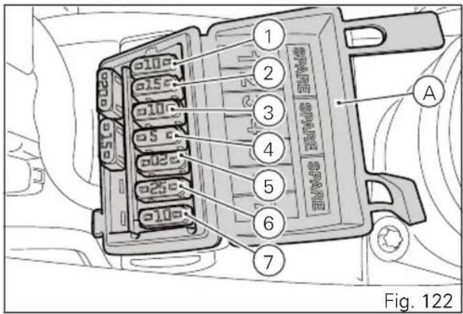
The main fuse (C) is positioned on the solenoid starter (D). Remove the fuse cap (E) to reach it. A blown fuse can be identified by breakage of the inner filament (F).

Important
Switch the ignition key to OFF before replacing the fuse to avoid possible short-circuits.

Warning
Never use a fuse with a rating other than specified. Failure to observe this rule may damage the electric system or even cause fire.
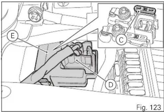
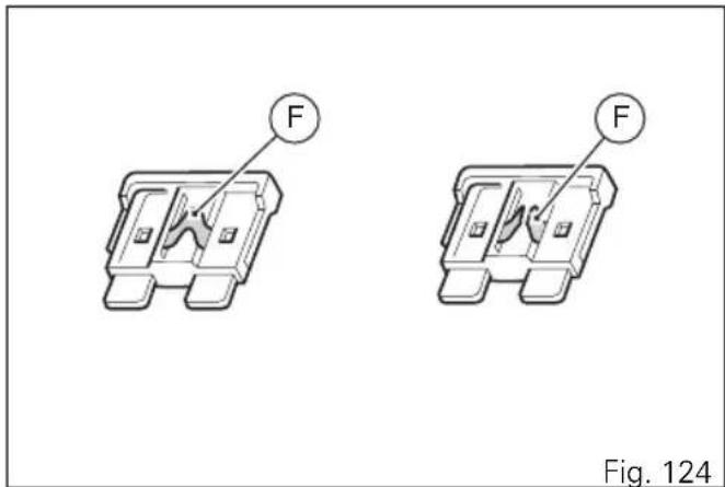
Injection/electric system diagram key
B Blue
W White
V Violet
Bk Black
Y Yellow
R Red
Lb Light blue
Gr Grey
G Green
Bn Brown
O Orange
P Pink

Note
The electric system wiring diagram is at the end
of this manual.
Routine maintenance record
Routine maintenance record
| KM NAME | DUCATI SERVICE | MILEAGE (KM) DATE |
| 1000 | ||
| 12000 | ||
| 24000 | ||
| 36000 | ||
| 48000 | ||
| 60000 |
bar
| Category | Value | | :--- | :--- | | Stampato 0 / 20153 | | | Cod. 913:7:286:1A | |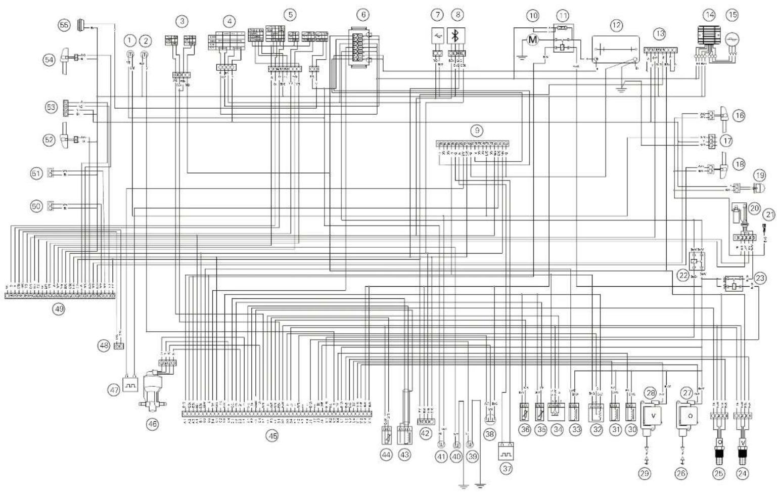
flowchart
graph TD
    A["①"] --> B["②"]
    B --> C["③"]
    C --> D["④"]
    D --> E["⑤"]
    E --> F["⑥"]
    F --> G["⑦"]
    G --> H["⑧"]
    H --> I["⑨"]
    I --> J["⑩"]
    J --> K["⑪"]
    K --> L["⑫"]
    L --> M["⑬"]
    M --> N["⑭"]
    N --> O["⑮"]
    O --> P["⑯"]
    P --> Q["⑰"]
    Q --> R["⑱"]
    R --> S["⑲"]
    S --> T["⑳"]
    T --> U["㉑"]
    U --> V["㉒"]
    V --> W["㉓"]
    W --> X["㉔"]
    X --> Y["㉕"]
    Y --> Z["㉖"]
    Z --> AA["㉗"]
    AA --> AB["㉘"]
    AB --> AC["㉙"]
    AC --> AD["㉚"]
    AD --> AE["㉛"]
    AE --> AF["㉜"]
    AF --> AG["㉝"]
    AG --> AH["㉞"]
    AH --> AI["㉟"]
    AI --> AJ["㉟A"]
    AJ --> AK["㉟B"]
    AK --> AL["㉟C"]
    AL --> AM["㉟D"]
    AM --> AN["㉟E"]
    AN --> AO["㉟F"]
    AO --> AP["㉟G"]
    AP --> AQ["㉟H"]
    AQ --> AR["㉟I"]
    AR --> AS["㉟J"]
    AS --> AT["㉟K"]
    AT --> AU["㉟L"]
    AU --> AV["㉟M"]
    AV --> AW["㉟N"]
    AW --> AX["㉟O"]
    AX --> AY["㉟P"]
    AY --> AZ["㉟Q"]
    AZ --> BA["㉟R"]
    BA --> BB["㉟S"]
    BB --> BC["㉟T"]
    BC --> BD["㉟U"]
    BD --> BE["㉟V"]
    BE --> BF["㉟W"]
    BF --> BG["㉟X"]
Scrambler
SCRAMBLER DUCATI
natural_image
Yellow silhouette of a motorcycle on dark background (no text or symbols)Ducati Motor Holding spa www.ducati.com
Via Cavalieri Ducati, 340132 Bologna, Italy Ph. +39 051 6413111 Fax +39 051 406580
A Sole Shareholder Company subject to the Management and Coordination activities of AUDI AG
- SCRAMBLER DUCATI
- Table of contents
- Introduction
- Safety guidelines
- Warning symbols used in the manual
- Warning
- Important
- Note
- Intended use
- Rider's obligations
- Rider's training
- Apparel
- Safety "Best Practices"
- Refuelling
- Carrying the maximum load allowed
- Brake dust
- Coolant
- Engine identification number
- Customisations
- ICON
- URBAN ENDURO
- FULL THROTTLE
- CLASSIC
- Instrument panel (Dashboard)
- Instrument panel
- 9) ABS LIGHTS (AMBER YELLOW).
- Technological Dictionary Anti-lock Braking System (ABS) 9M
- Function push-buttons
- Parameter setting/displaying
- Main functions
- Additional information
- Motorcycle speed
- Engine rpm indication (RPM)
- Menu 1 functions
- Odometer (TOT)
- Trip meter 1 (TRIP 1)
- Trip meter 2 (TRIP 2)
- Partial fuel reserve counter (TRIP FUEL)
- Ambient air temperature (AIR)
- Errors
- Error warnings
- Error icons table
- WARNING LIGHT / ERROR MESSAGE ERROR
- Clock
- High engine temperature
- Service indication (SERVICE)
- OIL SERVICE zero warning
- DESMO SERVICE indication
- Setting menu
- ABS control uni enabling/disabling
- Battery voltage
- Instrument panel back-lighting setting (B.LIGHT)
- Clock setting function (CLOCK)
- Pin Code
- Entering the PIN CODE
- Changing the PIN CODE
- Setting the units of measurement
- DEFAULT setting
- Light control
- Turn indicators
- Hazard function
- Immobilizer system
- Keys
- Operation
- Duplicate keys
- Entering PIN CODE function for overriding purposes
- Controls
- Key-operated ignition switch and steering lock
- Left-hand switch
- Clutch lever
- Right-hand switch
- Throttle twistgrip
- Front brake lever
- Rear brake pedal
- Gear change pedal
- Main components and devices
- Position on the vehicle
- Tank filler plug
- Opening
- Closing
- Seat lock
- Side stand
- USB connection
- Adjusting the rear shock absorber
- Riding the motorcycle
- Pre-ride checks
- ABS light
- ABS device
- Starting the engine
- Moving off
- Braking
- Anti-Lock Braking System (ABS)
- Stopping the motorcycle
- Parking
- Tool kit and accessories
- Main maintenance operations
- Check brake fluid level
- Brake system
- Changing the air filter
- Charging the battery
- Lubricating cables and joints
- Adjusting the throttle cable
- Checking drive chain tension
- Lubricating the drive chain
- Replacing the headlight bulbs
- Aligning the headlight
- Tubeless tyres
- Tyre repair or change (Tubeless tyres)
- Warning Punctured
- Warning Do not rem
- Note Have t
- Check engine oil level
- Viscosity
- SAE 15W-50
- Cleaning the motorcycle
- Storing the motorcycle
- Important notes
- Scheduled maintenance chart
- Technical data
- Weights
- Engine
- Timing system
- Performance data
- Spark plugs
- Fuel system
- Brakes
- FRONT
- Transmission
- Frame
- Wheels
- Tyres
- Suspensions
- Rear
- Exhaust system
- Available colours
- Scrambler ICON
- Scrambler FULL THROTTLE
- Scrambler CLASSIC
- Fuses
- Injection/electric system diagram key
- Routine maintenance record
Brand : DUCATI
Model : Scrambler 800 (2000)
Category : Motorcycle