USER MANUAL Granit 1980i HONEYWELL
Granit 1910i, 1911i, 1980i, 1981i
Area-Imaging Scanners
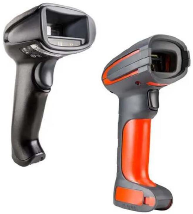
natural_image
Two barcode scanner devices, one black and one orange, shown against a white background (no text or symbols visible)
User Guide
Disclaimer
Honeywell International Inc. ("HII") reserves the right to make changes in specifications and other information contained in this document without prior notice, and the reader should in all cases consult HII to determine whether any such changes have been made. The information in this publication does not represent a commitment on the part of HII.
HII shall not be liable for technical or editorial errors or omissions contained herein; nor for incidental or consequential damages resulting from the furnishing, performance, or use of this material. HII disclaims all responsibility for the selection and use of software and/or hardware to achieve intended results.
This document contains proprietary information that is protected by copyright. All rights are reserved. No part of this document may be photocopied, reproduced, or translated into another language without the prior written consent of HII.
© 2010-2017 Honeywell International Inc. All rights reserved.
Web Address: www.honeywellaidc.com
Microsoft ^® Windows ^® , Windows NT ^® , Windows 2000, Windows ME, Windows XP, and the Windows logo are trademarks or registered trademarks of Microsoft Corporation.
The Bluetooth ^® word mark and logos are owned by Bluetooth SIG, Inc.
Other product names or marks mentioned in this document may be trademarks or registered trademarks of other companies and are the property of their respective owners.
For patent information, refer to www.hsmpats.com.
TABLE OF CONTENTS
Customer Support ......xvii
Technical Assistance ...... xvii
Product Service and Repair....xvii
Limited Warranty ...... xvii
Send Feedback ...... xvii
Chapter 1 - Get Started .... 1
About This Manual....1
Unpack Your Device....1
Connect the Device....1
Connect with USB....1
Connect with Keyboard Wedge 4
Connect with RS232 Serial Port 6
Connect with RS485....8
Mount a CCB01-010BT Charge Base....9
Mount a CCB02-100BT/CCB05-100BT Base 9
Reading Techniques.... 11
Xenon 1900/1902/1910/1912 and Granit 1910i/1911i ...... 11
Granit 1980i/1981i.... 11
Menu Bar Code Security Settings.... 12
Set Custom Defaults.... 12
Reset the Custom Defaults.... 13
Chapter 2 - Program the Interface .... 15
Introduction.... 15
Program the Interface - Plug and Play 15
Keyboard Wedge 15
Laptop Direct Connect ....16
RS232 Serial Port....16
RS485....16
RS485 Packet Mode....17
USB IBM SurePos 18
USB PC or Macintosh Keyboard 18
USB HID....19
USB Serial....19
CTS/RTS Emulation....19
ACK/NAK Mode....20
Remote MasterMind™ for USB....20
Verifone ^® Ruby Terminal....20
Gilbarco ^® Terminal....21
Honeywell Bioptic Aux Port 21
Datalogic™ Magellan® Aux Port....21
NCR Bioptic Aux Port....22
Wincor Nixdorf Terminal....22
Wincor Nixdorf Beetle™ Terminal 22
Wincor Nixdorf RS232 Mode A....23
Keyboard Country Layout....23
Keyboard Style ....30
Keyboard Conversion 32
Control Character Output....32
Keyboard Modifiers....33
RS232 Modifiers 34
RS232 Baud Rate 34
RS232 Word Length: Data Bits, Stop Bits, and Parity 35
RS232 Receiver Time-Out 36
RS232 Handshake....37
RS232 Timeout....37
XON/XOFF 38
ACK/NAK....38
Scanner to Bioptic Communication 38
Scanner-Bioptic Packet Mode....39
Scanner-Bioptic ACK/NAK Mode....39
Scanner-Bioptic ACK/NAK Timeout 39
Chapter 3 - Cordless System Operation: Xenon 1902g/1912 and Granit 1911i/1981i....41
How the Cordless Charge Base/Access Point Works....41
Link the Scanner to a Charge Base....41
Link the Scanner to an Access Point....42
Replace a Linked Scanner 43
Communication Between the Cordless System and the Host....43
Program the Scanner and Base or Access Point 44
RF (Radio Frequency) Module Operation....44
System Conditions....44
Page Button....45
Page Button and Presentation Modes 46
Temporary Streaming Presentation Timeout....46
About the Battery 47
Charge Information 47
Battery Recommendations....47
Safety Precautions for Lithium Batteries....48
Proper Disposal of the Battery 48
Beeper and LED Sequences and Meaning 48
Scanner LED Sequences and Meaning....49
Base/Access Point LED Sequences and Meaning....49
Base Power Communication Indicator 50
Reset Scanner....50
Scan While in Base Cradle....50
Base Charge Modes....51
Page 51
Page Mode 51
Page Pitch....52
Error Indicators....52
Beeper Pitch - Base Error....52
Number of Beeps - Base Error ....53
Scanner Report....53
Scanner Address 53
Base or Access Point Address....54
Scanner Modes....54
Charge Only Mode 54
Charge and Link Mode....54
Linked Modes 55
Unlink the Scanner....55
Override Locked Scanner....56
Out-of-Range Alarm....56
Alarm Sound Type....56
Scanner Power Time-Out Timer....57
Flexible Power Management....58
Batch Mode....59
Batch Mode Beep....60
Batch Mode Storage 60
Batch Mode Quantity....61
Enter Quantities....61
Batch Mode Output Order 63
Total Records....63
Delete Last Code 64
Clear All Codes 64
Transmit Records to Host 64
Batch Mode Transmit Delay....64
Multiple Scanner Operation....65
Scanner Name 65
Application Work Groups 67
Application Work Group Selection....67
Reset the Factory Defaults: All Application Work Groups....68
Reset the Custom Defaults: All Application Work Groups 69
Use the Scanner with Bluetooth Devices....69
Bluetooth Secure Simple Pairing (SSP)....69
Bluetooth HID Keyboard Connect....70
Virtual Keyboard....71
Bluetooth HID Keyboard Disconnect....71
Bluetooth Serial Port - PCs/Laptops....72
PDAs/Mobility Systems Devices 72
Change the Scanner's Bluetooth PIN Code....72
Minimize Bluetooth/ISM Band Network Activity ....72
Auto Reconnect Mode ....73
Maximum Link Attempts....73
Relink Time-Out 74
Bluetooth/ISM Network Activity Examples....75
Host Acknowledgment....75
Host ACK On/Off 77
Host ACK Timeout ....77
Host ACK Responses....77
Chapter 4 - Cordless System Operation: Xenon 1902g-BF....79
How the CCB01-010BT-BF Cordless Charge Base Works....79
Link the Scanner to a Charge Base....80
Replace a Linked Scanner....80
Communication Between the Cordless System and the Host....81
Program the Scanner and Base....81
RF (Radio Frequency) Module Operation....81
System Conditions....82
About the Instant Charge Pack....83
Charge Information 83
Beeper and LED Sequences and Meaning....83
Scanner 84
Low Power Alerts 84
Low Power Alert Range 85
Low Power Alert Flash Number 85
Low Power Alert Repeat....85
Low Power Alert Beep 86
Base....86
Base Communication and Scanning 86
Base Charge Status....87
Base Power Communication Indicator....87
Reset Scanner 87
Base Charge Modes....88
Page Button with Scanner Out of the Base....88
Page Button with Scanner in the Base....89
Temporary Streaming Presentation Timeout....89
Scan While in Base Cradle....90
Paging 90
Page Mode 90
Page Pitch 91
Linking Sound....91
Error Indicators....91
Beeper Pitch - Base Error....91
Number of Beeps - Base Error 92
Scanner Report....92
Scanner Address 92
Base Address 93
Scanner Modes....93
Charge Only Mode 93
Charge and Link Mode....93
Linked Modes 93
Unlink the Scanner....94
Override Locked Scanner....95
Out-of-Range Alarm 95
Alarm Sound Type 95
Scanner Power Time-Out Timer 96
Flexible Power Management....97
Batch Mode 98
Batch Mode Beep 99
Batch Mode Storage....99
Batch Mode Quantity....100
Enter Quantities....100
Batch Mode Output Order 102
Total Records....102
Delete Last Code....102
Clear All Codes....103
Transmit Records to Host....103
Batch Mode Transmit Delay 103
Scanner Name....104
Change the Scanner's Bluetooth PIN Code....105
Minimize Bluetooth/ISM Band Network Activity 105
Auto Reconnect Mode 105
Maximum Link Attempts....106
Relink Time-Out 107
Bluetooth/ISM Network Activity Examples....107
Host Acknowledgment....108
Host ACK On/Off 109
Host ACK Timeout ....109
Host ACK Responses....110
Power Up Beeper 111
Beep on BEL Character 112
Trigger Click....112
Good Read and Error Indicators....112
Beeper – Good Read ....112
Beeper Volume – Good Read 113
Beeper Pitch – Good Read 113
Vibrate – Good Read.... 113
Beeper Pitch – Error 114
Beeper Duration – Good Read.... 115
LED - Good Read 115
Number of Beeps – Good Read.... 115
Number of Beeps – Error....115
Beeper Volume Max 116
Good Read Delay 116
User-Specified Good Read Delay.... 117
Trigger Modes 117
Manual Trigger 117
Trigger Toggle 117
Serial Trigger 119
Read Time-Out 119
Presentation Mode....120
Presentation LED Behavior after Decode....120
Presentation Sensitivity....120
Presentation Centering....121
In-Stand Sensor Mode....122
Poor Quality Codes....123
Poor Quality 1D Codes....123
Poor Quality PDF Codes 123
CodeGate ^® 124
Streaming Presentation™ Mode....124
Streaming Presentation In-Stand 125
Mobile Phone Read Mode....125
Hands Free Time-Out....126
Reread Delay....126
User-Specified Reread Delay....127
2D Reread Delay....127
Character Activation....127
Activation Character....128
End Character Activation After Good Read ....128
Character Activation Timeout....129
Character Deactivation....129
Deactivation Character 129
Illumination Lights....130
Aimer Delay....130
User-Specified Aimer Delay....131
Aimer Mode 131
Centering....131
Single Code Centering....132
Custom Centering....132
Preferred Symbology ....134
High Priority Symbology....135
Low Priority Symbology ....135
Preferred Symbology Time-out....135
Preferred Symbology Default ....136
Output Sequence Overview....136
Output Sequence Editor....136
To Add an Output Sequence....136
Other Programming Selections....137
Output Sequence Example....137
Output Sequence Editor....138
Partial Sequence....138
Require Output Sequence....139
Multiple Symbols 139
No Read....140
Video Reverse....140
Working Orientation....141
Chapter 6 - Healthcare Settings ...... 143
Quiet Operations - Combination Codes....143
Silent Mode with Flashing LED 143
Silent Mode with Long LED 144
Very Low Beeper (Nighttime Mode)....144
Low Beeper (Daytime Mode) 145
Quiet Operations - LED and Volume Settings 145
Linking LED Colors and Sound 145
Number of LED Flashes 146
LED Flash Rate....146
LED Solid (No Flash)....147
Page Volume Control....147
Out-of-Range Alarm Volume.... 148
Out-of-Range Delay....149
Chapter 7 - Data Edit ....151
Prefix/Suffix Overview....151
Points to Keep In Mind....151
Add a Prefix or Suffix: 152
Example: Add a Tab Suffix to All Symbologies....152
Clear One or All Prefixes or Suffixes 152
Add a Carriage Return Suffix to All Symbologies 153
Prefix Selections....153
Suffix Selections....153
Function Code Transmit....154
Intercharacter, Interfunction, and Intermessage Delays....154
Intercharacter Delay 154
User Specified Intercharacter Delay.... 155
Interfunction Delay 155
Intermessage Delay....156
Data Format Editor Introduction....157
Add a Data Format....158
Other Programming Selections.... 159
Terminal ID Table....160
Data Format Editor Commands....160
Send Commands 160
Move Commands....165
Search Commands....167
Miscellaneous Commands....169
Data Formatter....173
Data Format Non-Match Error Tone....174
Primary/Alternate Data Formats 175
Single Scan Data Format Change....175
Chapter 9 - Symbologies....177
All Symbologies....178
Message Length Description....178
Codabar....179
Code 39....181
Interleaved 2 of 5....185
NEC 2 of 5....186
NEC 2 of 5 Message Length ....187
Code 93....187
Straight 2 of 5 Industrial (three-bar start/stop)....189
Straight 2 of 5 IATA (two-bar start/stop)....190
Straight 2 of 5 IATA Redundancy....190
Matrix 2 of 5....191
Code 11....192
Code 128....193
ISBT 128 Concatenation....193
Code 128 Redundancy....193
GS1-128 195
Telepen....196
UPC-A....197
UPC-A/EAN-13 with Extended Coupon Code 199
Coupon GS1 DataBar Output....200
UPC-EO 201
UPC-EO Addenda Required....201
UPC-E1 203
EAN/JAN-13 204
EAN/JAN-13 Addenda Separator 206
ISBN Translate....206
EAN/JAN-8....207
MSI....209
GS1 DataBar Omnidirectional....211
GS1 DataBar Limited 211
GS1 DataBar Expanded 212
Trioptic Code 212
Codablock A 213
Codablock F 214
Label Code....214
PDF417 215
MacroPDF417 216
MicroPDF417 216
GS1 Composite Codes....217
GS1 Emulation....218
TCIF Linked Code 39 (TLC39)....219
QR Code....219
Data Matrix....221
MaxiCode 222
Aztec Code 223
Chinese Sensible (Han Xin) Code 224
Postal Codes - 2D 225
Planet Code Check Digit....229
Postnet Check Digit....229
Australian Post Interpretation 229
Postal Codes - Linear....230
China Post (Hong Kong 2 of 5) 230
Korea Post....231
232
Chapter 10 - Imaging Commands....233
Single-Use Basis 233
Command Syntax....233
Image Snap - IMGSNP 234
IMGSNP Modifiers 234
Image Ship - IMGSHP 237
IMGSHP Modifiers 238
Image Size Compatibility....246
Intelligent Signature Capture - IMGBOX....247
Signature Capture Optimize 247
IMGBOX Modifiers 248
RF Default Imaging Device 252
Chapter 11 - Utilities....253
To Add a Test Code I.D. Prefix to All Symbologies....253
Show Decoder Revision 253
Show Scan Driver Revision....253
Show Software Revision 254
Show Data Format 254
Test Menu 254
TotalFreedom....254
Application Plug-Ins (Apps)......255
EZConfig Cloud for Scanning Introduction....255
EZConfig Cloud for Scanning Operations 256
Install EZConfig Cloud for Scanning 256
Reset the Factory Defaults 257
Chapter 12 - Serial Programming Commands....259
Conventions 259
Menu Command Syntax 259
Query Commands....260
Trigger Commands....262
Reset the Custom Defaults 263
Menu Commands 264
Chapter 13 - Product Specifications....295
Xenon 1900/1900h/1910 Corded Scanner Product Specifications .... 295
Xenon 1902/1902h/1912 Cordless Scanner Product Specifications ...... 296
Xenon 1902g-BF Scanner Product Specifications 298
Granit 1910i Industrial Corded Scanner Product Specifications.... 299
Granit 1911i Industrial Cordless Scanner Product Specifications.... 300
Granit 1980i Industrial Full Range Corded Scanner Product Specifications... 301
Granit 1981i Industrial Full Range Cordless Scanner Product Specifications 302
CCB01-010BT Charge Base Product Specifications 304
CCB01-010BT-BF Charge Base Product Specifications.... 305
CCB02-100BT/CCB05-100BT Industrial Charge Base Product Specifications305
Depth of Field Charts 306
Xenon B&W Scanner Typical Performance.... 306
Xenon B&W Scanner Guaranteed Performance....307
Xenon Color Scanner (Model COL) Typical Performance.... 308
Xenon Color Scanner (Model COL) Guaranteed Performance.... 308
Granit 1910i/1911i Scanner Typical Performance.... 309
Granit 1910i/1911i Scanner Guaranteed Performance.... 309
Granit 1980i/1981i Scanner Typical Performance (200 lux) 310
Granit 1980i/1981i Scanner Guaranteed Performance (200 lux) ...... 310
Standard Connector Pinouts 311
Keyboard Wedge 312
Serial Output 312
RS485 Output 312
USB 313
Required Safety Labels 314
Xenon 1900/1910/1902/1912 Scanner 314
CCB01-010BT/CCB01-010BT-BF Base 315
Granit 1910i/1911i/1980i/1981i Scanner....316
CCB02-100BT/CCB05-100BT Base 317
Chapter 14 - Maintenance and Troubleshooting .... 319
Repairs....319
Maintenance....319
Cleaning the Scanner 319
Cleaning the Window 319
Health Care Housing 320
Inspecting Cords and Connectors....320
Replacing Cables in Corded Scanners 320
Replacing a Xenon Interface Cable....321
Replacing a Granit Interface Cable 321
Replacing Cables and Batteries in Cordless Systems 321
Replacing an Interface Cable in a Base 321
Changing a Xenon Scanner Battery....322
Changing a Granit Scanner Battery....323
Troubleshooting a Corded Scanner 323
Troubleshooting a Cordless System....324
Troubleshooting a Base 324
Troubleshooting a Cordless Scanner 325
Chapter A - Reference Charts 327
Symbology Charts....327
Linear Symbologies....327
2D Symbologies 328
Postal Symbologies 329
ASCII Conversion Chart (Code Page 1252)....330
Lower ASCII Reference Table....331
ISO 2022/ISO 646 Character Replacements 334
Keyboard Key References....337
Sample Symbols 339
Programming Chart.... 341
Customer Support
Technical Assistance
To search our knowledge base for a solution or to log in to the Technical Support portal and report a problem, go to www.hsmcontactsupport.com.
Product Service and Repair
Honeywell International Inc. provides service for all of its products through service centers throughout the world. To obtain warranty or non-warranty service, you must first obtain a Return Material Authorization number (RMA #) and then return your product to Honeywell (postage paid) with a copy of the dated purchase record. To learn more, go to www.honeywellaidc.com and select Service & Repair at the bottom of the page.
Limited Warranty
For warranty information, go to www.honeywellaidc.com and click Get Resources > Product Warranty.
Send Feedback
Your feedback is crucial to the continual improvement of our documentation. To provide feedback about this manual, contact the Honeywell Technical Communications department at ACSHSMTechnicalCommunications@honeywell.com.
About This Manual
This User's Guide provides installation and programming instructions for the Xenon™ 1900 and 1910 corded area-imaging scanners, the Xenon 1902 and 1912 cordless area-imaging scanners, the Granit 1910i and 1980i corded industrial scanners, and the Granit 1911i and 1981i cordless industrial scanners. Product specifications, dimensions, warranty, and customer support information are also included.
Honeywell bar code scanners are factory programmed for the most common terminal and communications settings. If you need to change these settings, programming is accomplished by scanning the bar codes in this guide.
An asterisk (*) next to an option indicates the default setting.
Unpack Your Device
After you open the shipping carton containing the product, take the following steps:
- Check for damage during shipment. Report damage immediately to the carrier who delivered the carton.
- Make sure the items in the carton match your order.
- Save the shipping container for later storage or shipping.
Connect the Device
Connect with USB
A scanner or a cordless base can be connected to the USB port of a computer.
- Connect the appropriate interface cable to the device first, then to the computer.

- If you are connecting a Granit scanner, make sure the cable is pushed tightly into the scanner. Loosen the locking plate and slide it over the base of the cable connector to lock the cable in place. Tighten the screw.

CCB02-100BT/
CCB05-100BT Base
USB Connection:

Note: The power supply must be ordered separately, if needed.
- If you are connecting a CCB01-010BT or CCB01-010BT-BF Base, make sure the cables are secured in the wireways in the bottom of the cordless base and the base sits flat on a horizontal surface. If you are connecting a CCB02-100BT or CCB05-100BT Base, see Mount a CCB02-100BT/CCB05-100BT Base on page 9.
- The scanner beeps.
- Verify the scanner or cordless base operation by scanning a bar code from the Sample Symbols, beginning on page 339.
The unit defaults to a USB PC Keyboard. Refer to page 18 for other USB terminal settings.
For additional USB programming and technical information, refer to “USB Application Note,” available at www.honeywellaidc.com.
Connect with Keyboard Wedge
A scanner or cordless base can be connected between the keyboard and PC as a "keyboard wedge," where the scanner provides data output that is similar to keyboard entries.
Note: The Granit 1980i does not support the keyboard wedge interface.
The following is an example of a keyboard wedge connection:
- Turn off power and disconnect the keyboard cable from the back of the terminal/computer.
- Connect the appropriate interface cable to the device and to the terminal/computer.
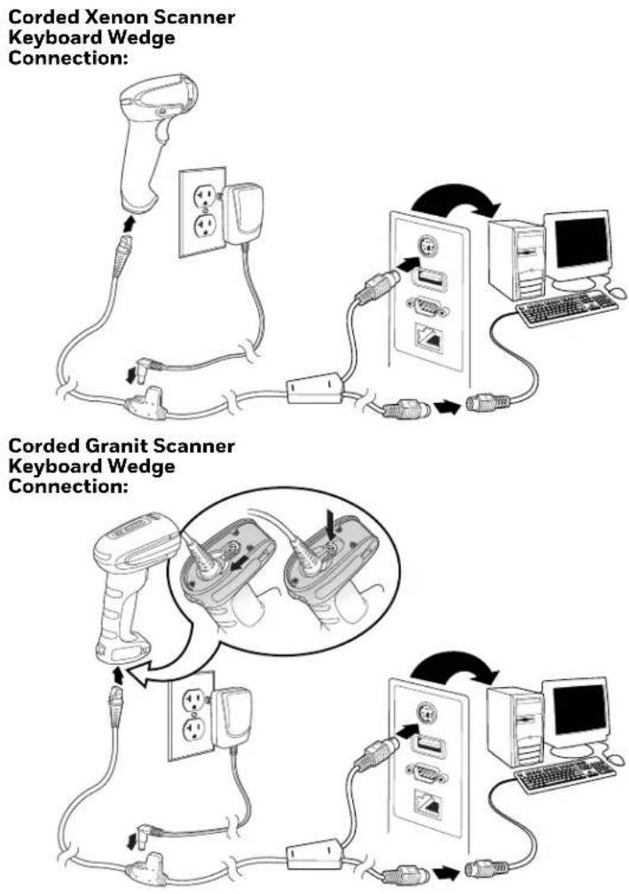
flowchart
graph TD
    A["Corded Xenon Scanner Keyboard Wedge Connection"] --> B["Switch"]
    B --> C["Computer"]
    D["Corded Granit Scanner Keyboard Wedge Connection"] --> E["Switch"]
    E --> F["Computer"]
    G["Corded Granit Scanner Keyboard Wedge Connection"] --> H["Switch"]
    H --> I["Computer"]
- If you are connecting a Granit scanner, make sure the cable is pushed tightly into the scanner. Loosen the locking plate and slide it over the base of the cable connector to lock the cable in place. Tighten the screw.
CCB01-010BT/CCB01-010BT-BF Base Keyboard Wedge Connection:
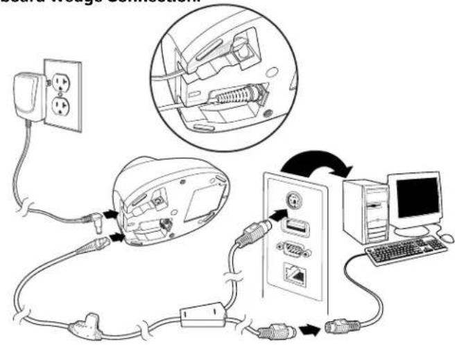
CCB02-100BT/CCB05-100BT Base Keyboard Wedge Connection:

Note: The power supply must be ordered separately, if needed.
-
If you are connecting a CCB01-010BT or CCB01-010BT-BF Base, make sure the cables are secured in the wireways in the bottom of the cordless base and the base sits flat on a horizontal surface. If you are connecting a CCB02-100BT or CCB05-100BT Base, see Mount a CCB02-100BT/CCB05-100BT Base on page 9.
-
Turn the terminal/computer power back on. The scanner beeps.
-
Verify the scanner or cordless base operation by scanning a bar code from the Sample Symbols, beginning on page 339. The scanner beeps once. If using a Granit scanner, it also vibrates.
The unit defaults to an IBM PC AT and compatibles keyboard wedge interface with a USA keyboard. A carriage return (CR) suffix is added to bar code data.
Connect with RS232 Serial Port
-
Turn off power to the terminal/computer.
-
Connect the appropriate interface cable to the scanner.
Note: For the scanner or cordless base to work properly, you must have the correct cable for your type of terminal/computer.
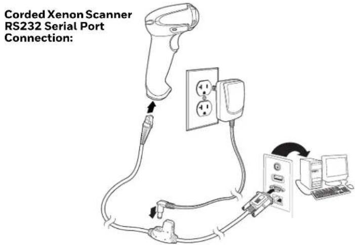
Corded Granit Scanner RS232 Serial Port Connection:

- If you are connecting a Granit scanner, make sure the cable is pushed tightly into the scanner. Loosen the locking plate and slide it over the base of the cable connector to lock the cable in place. Tighten the screw.
CCB01-010BT/CCB01-010BT-BF Base RS232 Serial Port Connection:

CCB02-100BT/CCB05/100BT Base RS232 Serial Port Connection:
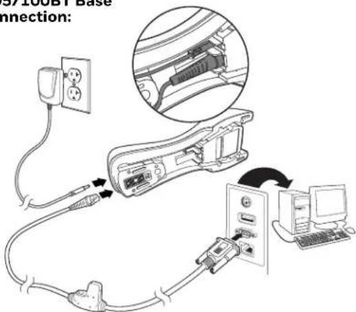
Note: The power supply must be ordered separately, if needed.
- If you are connecting a CCB01-010BT or CCB01-010BT-BF Base, make sure the cables are secured in the wireways in the bottom of the cordless base and the base sits flat on a horizontal surface. If you are connecting a CCB02-100BT or CCB05-100BT Base, see Mount a CCB02-100BT/CCB05-100BT Base on page 9.
- Plug the serial connector into the serial port on your computer. Tighten the two screws to secure the connector to the port.
- Once the scanner or cordless base has been fully connected, power up the computer.
This interface programs 115,200 baud, 8 data bits, no parity, and 1 stop bit.
Connect with RS485
A Xenon scanner or cordless base can be connected for an IBM POS terminal interface. (This interface is not available in the Granit devices.)
- Connect the appropriate interface cable to the device, then to the computer.
Corded Xenon Scanner RS485 Connection:
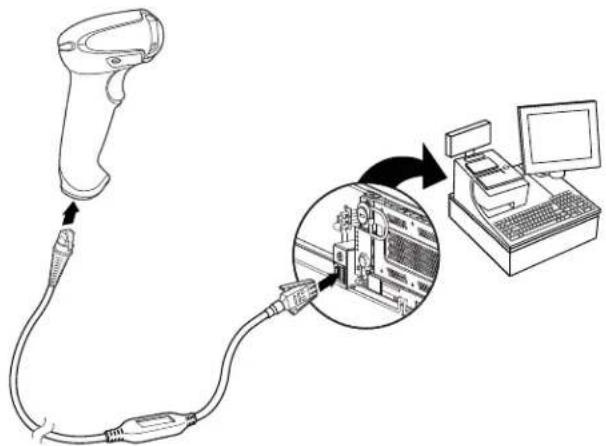
natural_image
Diagram showing a handheld device connected to a computer via a close-up of its internal components (no text or symbols present)
CCB01-010BT/CCB01-010BT-BF Base RS485 Connection:

Note: The power supply must be ordered separately, if needed.
- Make sure the cables are secured in the wireways in the bottom of the cordless base and the base sits flat on a horizontal surface.
- Turn the terminal/computer power back on. The scanner beeps.
- Verify the scanner or cordless base operation by scanning a bar code from the Sample Symbols, beginning on page 339. The scanner beeps once. If using a Granit scanner, it also vibrates.
For further RS485 settings, refer to RS485, page 16.
Mount a CCB01-010BT Charge Base

Mount a CCB02-100BT/CCB05-100BT Base
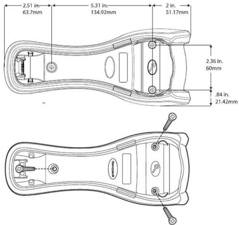
The CCB02-100BT or CCB05-100BT Base can be mounted on either a horizontal or vertical surface. The cables can be routed through either the top or the bottom of the base.
The cables can be routed down through the bottom of the base, securing the cables in the wireways.

natural_image
Technical line drawing of a mechanical clamp or wire assembly (no text or symbols)
The cables can also be routed up through the top of the base, crossing them over and securing the cables in the wireways.

natural_image
Technical line drawing of a mechanical device with internal components and wiring (no text or symbols)
When routing the cables up through the top of the base, be sure to cross the cables over before placing in the wireways. If not, too much strain is placed on the cable connectors.

natural_image
Diagram of a hand holding a cable with a red X mark indicating prohibition (no text or symbols present)
When mounted on a vertical surface, a locking system is used to secure the scanner when it is in the stand. When mounted on a horizontal surface, the locking mechanism should be set to unlocked (pushed up). When mounted on a vertical surface, the locking mechanism should be set to locked (pushed down).

Use 30mm screws, appropriate for the mounting surface material, to mount the base securely.
Reading Techniques
Xenon 1900/1902/1910/1912 and Granit 1910i/1911i
The Xenon 1900/1902 scanners have a view finder that projects a bright red aiming beam that corresponds to the scanner's horizontal field of view. The Xenon 1910/1912 and Granit 1910i/1911i scanners have an aiming pattern. The aiming beam or pattern should be centered over the bar code, but it can be positioned in any direction for a good read.
Linear bar codes with aiming beam

2D Matrix symbol with aiming beam
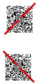
Linear bar codes with aiming pattern

2D Matrix symbol with aiming pattern

Granit 1980i/1981i
The Granit 1980i/1981i scanners use a laser aimer (red dot) and a red LED (red box) to locate bar codes. Use the red LED when scanning at a near distance (less than 11.8 inches / 30 cm) and center the box over the bar code. The laser aimer (red dot) appears to the right of the center of the bar code. Use the laser aimer (red dot) when scanning at a far distance (up to 50 feet / 15.2 meters) and aim at the
center of the bar code. At far distances the red box may not be apparent. For both near distance and far distance, the aimers can be positioned in any direction for a good read.

The aiming beam or pattern is smaller when the scanner is closer to the code and larger when it is farther from the code. Symbologies with smaller bars or elements (mil size) should be read closer to the unit. Symbologies with larger bars or elements (mil size) should be read farther from the unit. To read single or multiple symbols (on a page or on an object), hold the scanner at an appropriate distance from the target, pull the trigger, and center the aiming beam or pattern on the symbol. If the code being scanned is highly reflective (e.g., laminated), it may be necessary to tilt the code up 15^ to 18^ to prevent unwanted reflection.
Honeywell scanners are programmed by scanning menu bar codes or by sending serial commands to the scanner. If you want to restrict the ability to scan menu codes, you can use the Menu Bar Code Security settings. Contact the nearest technical support office (see Technical Assistance on page xvii) for further information.
Set Custom Defaults
You have the ability to create a set of menu commands as your own, custom defaults. To do so, scan the Set Custom Defaults bar code below before scanning the menu commands for your custom defaults. If a menu command requires scanning numeric codes from the Programming Chart, beginning on page 341, then a
Save code, that entire sequence will be saved to your custom defaults. When you have entered all the commands you want to save for your custom defaults, scan the Save Custom Defaults bar code.
MNUCDP
Set Custom Defaults

MNUCDS
Save Custom Defaults
Note: When using a cordless system, the Custom Defaults settings apply to all workgroups. Scanning the Save Defaults bar code also causes both the scanner and the base or Access Point to perform a reset and become unlinked. The scanner must be placed in its base to re-establish the link before any setup codes are entered. If using an Access Point, the linking bar code must be scanned. See Cordless System Operation: Xenon 1902g/1912 and Granit 1911i/1981i beginning on page 41, or Cordless System Operation: Xenon 1902g-BF beginning on page 79 for additional information.
You may have a series of custom settings and want to correct a single setting. To do so, just scan the new setting to overwrite the old one. For example, if you had previously saved the setting for Beeper Volume at Low to your custom defaults, and decide you want the beeper volume set to High, just scan the Set Custom Defaults bar code, then scan the Beeper Volume High menu code, and then Save Custom Defaults. The rest of the custom defaults will remain, but the beeper volume setting will be updated.
Reset the Custom Defaults
If you want the custom default settings restored to your scanner, scan the Activate Custom Defaults bar code below. This is the recommended default bar code for most users. It resets the scanner to the custom default settings. If there are no custom defaults, it will reset the scanner to the factory default settings. Any settings that have not been specified through the custom defaults will be defaulted to the factory default settings.

DEFAULT
Activate Custom Defaults
Note: If using a cordless system, scanning this bar code also causes both the scanner and the base or Access Point to perform a reset and become unlinked. The scanner must be placed in its base to re-establish the link. If using an Access Point, the linking bar code must be scanned. See Cordless System Operation: Xenon 1902g/1912 and Granit 1911i/1981i beginning on page 41, or Cordless System Operation: Xenon 1902g-BF beginning on page 79 for additional information.
Introduction
This chapter describes how to program your system for the desired interface.
Program the Interface - Plug and Play
Plug and Play bar codes provide instant scanner set up for commonly used interfaces.
Note: After you scan one of the codes, power cycle the host terminal to have the interface in effect.
Keyboard Wedge
If you want your system programmed for an IBM PC AT and compatibles keyboard wedge interface with a USA keyboard, scan the bar code below. Keyboard wedge is the default interface.
Note: The Granit 1980i does not support the keyboard wedge interface.
Note: The following bar code also programs a carriage return (CR) suffix.

PAP AT
IBM PC AT and Compatibles with
CR suffix
Laptop Direct Connect
For most laptops, scanning the Laptop Direct Connect bar code allows operation of the scanner in parallel with the integral keyboard. The following Laptop Direct Connect bar code also programs a carriage return (CR) suffix and turns on Emulate External Keyboard (page 31).
Note: The Granit 1980i does not support Laptop Direct Connect.

PAPLTD
Laptop Direct Connect with CR suffix
RS232 Serial Port
The RS232 Interface bar code is used when connecting to the serial port of a PC or terminal. The following RS232 Interface bar code also programs a carriage return (CR) and a line feed (LF) suffix, baud rate, and data format as indicated below. It also changes the trigger mode to manual.
Option Setting
Baud Rate 115,200 bps
Data Format 8 data bits, no parity bit, 1 stop bit
PAP232
RS232 Interface
RS485
Scan one of the following “Plug and Play” codes to program the scanner for an IBM POS terminal interface.
Note: This interface is not supported in Granit devices.
After scanning one of these codes, you must power cycle the cash register.
PAPP5B
IBM Port 5B Interface

PAP9B1
IBM Port 9B
HHBCR-1 Interface

PAPP17
IBM Port 17 Interface
PAP9B2
IBM Port 9B
HHBCR-2 Interface
Each bar code above also programs the following suffixes for each symbology:
| Symbology | Suffix Symbology Suffix |
| EAN 8 OC Code 39 00 0A 0B |
| EAN 13 16 Interleaved 2 of 5 00 0D 0B |
| UPC A OD Code 128 * 00 0A 0B |
| UPC E 0A Code 128 ** 00 18 0B |
| MaxiCode | 00 2F 0B |
* Suffixes programmed for Code 128 with IBM 4683 Port 5B, IBM 4683 Port 9B HHBCR-1, and IBM 4683 Port 17 Interfaces
**Suffixes programmed for Code 128 with IBM 4683 Port 9 HHBCR-2 Interface
RS485 Packet Mode
The following selection allows you to break up large bar code data into smaller packets on an IBM POS terminal. To break up large bar codes into small packets, scan the Packet Mode On bar code below. Scan the Packet Mode Off bar code if you want large bar code data to be sent to the host in a single chunk. Default = Packet Mode Off.
RTLPDFO.
* Packet Mode Off
RTLPDF1.
Packet Mode On
RS485 Packet Length
If you are using Packet mode, you can specify the size of the data "packet" that is sent to the host. Scan the Packet Length bar code, then the packet size (from 20 - 256) from the Programming Chart, beginning on page 341, then Save. Default = 40.
RTLMPS
Packet Length
USB IBM SurePos
Scan one of the following "Plug and Play" codes to program the scanner for an IBM SurePos (USB handheld scanner) or IBM SurePos (USB tabletop scanner) interface.
Note: After scanning one of these codes, you must power cycle the cash register.

PAPSPH
USB IBM SurePos
(USB Handheld Scanner)
Interface

PAPSPT
USB IBM SurePos
(USB Tabletop Scanner)
Interface
Each bar code above also programs the following suffixes for each symbology:
| Symbology Suffix Symbology Suffix |
| EAN 8 OC Code 39 00 OA OB |
| EAN 13 16 Interleaved 2 of 5 00 OD OB |
| UPC A OD Code 128 | 00 18 OB |
| UPC E | OA | Code 39 00 OA OB |
USB PC or Macintosh Keyboard
Scan one of the following codes to program the scanner for USB PC Keyboard or USB Macintosh Keyboard. Scanning these codes also adds a CR suffix.

PAP124
USB Keyboard (PC)

TRMUSB134
USB Japanese Keyboard (PC)
USB HID
Scan the following code to program the scanner for USB HID bar code scanners.

PAP131
USB HID Bar Code Scanner
USB Serial
If you are using a Microsoft® Windows® PC, you will need to download the latest driver from the Honeywell website (www.honeywellaidc.com) and go to Get
Resources - Downloads - Software. The driver will use the next available COM Port number. Apple® Macintosh computers recognize the scanner as a USB CDC class device and automatically use a class driver.
After the driver is downloaded, scan the following code to program the scanner to emulate a regular RS232-based COM Port.

TRMUSB130.
USB Serial
No extra configuration (e.g., baud rate) is necessary.
Note: If you scan the USB Serial bar code either with an older Honeywell serial driver, or no driver installed, you may no longer be able to scan bar codes. If this happens, either uninstall the older driver versions and install the latest driver, or delete the specific device entry in Device Manager.
CTS/RTS Emulation

USBCTS1
CTS/RTS Emulation On

USBCTSO
* CTS/RTS Emulation Off
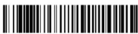
ACK/NAK Mode
USBACK1
ACK/NAK Mode On

USBACKD
* ACK/NAK Mode Off
Remote MasterMind™ for USB
When using a USB interface, you may wish to configure your scanner to communicate with Remote MasterMind Scanner Management Software (ReM). Scan the ReM On bar code to communicate with ReM. To disable this capability, scan ReM Off.

REMIFCO
ReM Off

REMIFC1
ReM On
Verifone® Ruby Terminal
Scan the following Plug and Play code to program the scanner for a Verifone Ruby terminal. This bar code sets the baud rate to 1200 bps and the data format to 8 data bits, mark parity bit, 1 stop bit. It also adds a line feed (LF) suffix and programs the following prefixes for each symbology:
Symbology Prefix
| UPC-AA |
| UPC-EA |
| EAN-8 FF |
| EAN-13 F |
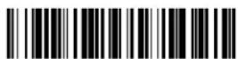
PAPRBY
Verifone Ruby Settings
Gilbarco® Terminal
Scan the following Plug and Play code to program the scanner for a Gilbarco terminal. This bar code sets the baud rate to 2400 bps and the data format to 7 data bits, even parity, 2 stop bits. It also adds a carriage return (CR) suffix and programs the following prefixes for each symbology:
Symbology Prefix
| UPC-AA |
| UPC-EE0 |
| EAN-8 FF |
| EAN-13 F |

PAPGLB
Gilbarco Settings
Honeywell Bioptic Aux Port
Scan the following Plug and Play code to program the scanner for a Honeywell bioptic scanner auxiliary port configuration. This bar code sets the baud rate to 38400 bps and the data format to 8 data bits, no parity, 1 stop bit.

PAPBIO
Honeywell Bioptic Settings
Datalogic™ Magellan® Aux Port
Scan the following Plug and Play code to program the scanner for a Datalogic Magellan auxiliary port configuration. This bar code sets the baud rate to 9600 bps and the data format to 8 data bits, no parity, 1 stop bit.

PAPMAG.
Datalogic Magellan Settings
NCR Bioptic Aux Port
Scan the following Plug and Play code to program the scanner for an NCR bioptic scanner auxiliary port configuration. The following prefixes are programmed for each symbology:
| Symbology Prefix Symbology Prefix |
| UPC-A A Interleaved 2 of 5 b | |
| UPC-E EO Code 128 f | |
| Code 32 a Pharmaceutical (PARAF) |
| EAN-8 FF Code 39 a | |
| EAN-13 F | |

PAPNCR
NCR Bioptic Settings
Wincor Nixdorf Terminal
Scan the following Plug and Play code to program the scanner for a Wincor Nixdorf terminal. This bar code sets the baud rate to 9600 bps and the data format to 8 data bits, no parity, 1 stop bit.

PAPWNX
Wincor Nixdorf Terminal Settings
Wincor Nixdorf Beetle™ Terminal
Scan the following Plug and Play code to program the scanner for a Wincor Nixdorf Beetle terminal. The following prefixes are programmed for each symbology:
| Symbology Prefix Symbology Prefix |
| Aztec Code | V Interleaved 2 of 5 I | | |
| Codabar | N | MaxiCode | T |
| Code 93 | L MicroPDF417 | S | |
| Code 128 K PDF417 | | Q | |
| Data Matrix | R | QR Code | U |
| EAN-8 B | Straight 2 of 5 IATA | H | |
| EAN-13 | A UPC-A A0 | | |
| GS1 DataBar | E | UPC-E C | |
| GS1-128 | P | All other bar codes | M |
Wincor Nixdorf RS232 Mode A
Scan the following Plug and Play code to program the scanner for a Wincor Nixdorf RS232 Mode A terminal. This bar code sets the baud rate to 9600 bps and the data format to 8 data bits, odd parity, 1 stop bit. The following prefixes are programmed for each symbology:
Note: This setting is not supported in Granit devices.
| Symbology Prefix Symbology Prefix |
| Code 128 K EAN-13 A | |
| Code 93 L GS1-128 K | |
| Codabar N Interleaved 2 of 5 I | |
| UPC-A AO | Plessey | O |
| UPC-E | C | Straight 2 of 5 IATA | H |
| EAN-8 | B | GS1 DataBar | E |
| All other bar codes | M | |

PAPWMA
Wincor Nixdorf RS232 Mode A Settings
Keyboard Country Layout
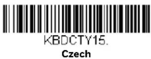
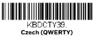
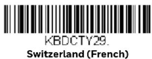
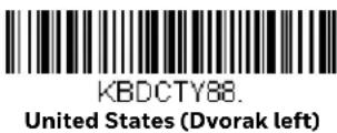
If your interface is USB Keyboard or Keyboard Wedge, your keyboard layout default is a US keyboard. To change this layout, scan the appropriate Keyboard Country bar code below. By default, national character replacements are used for the following characters: # \$ @ [ \ ] ^ ' { | } \~. Refer to the "ISO 2022/ISO 646 Character Replacements" on page A-334 to view the character replacements for each country.
Keyboard Countries

KBDCTYO
* United States
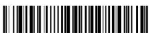
KBDCTY35.
Albania
Keyboard Countries (Continued)

KBDCTY81.
Azeri (Cyrillic)

KBDCTY80
Azeri (Latin)

KBDCTY82.
Belarus

KBDCTY1
Belgium
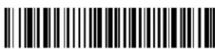
KBDCTY33.
Bosnia
KBDCTY16
Brazil
KBDCTY59
Brazil (MS)

KBDCTY52
Bulgaria (Cyrillic)

KBDCTY53
Bulgaria (Latin)

KBDCTY54
Canada (French legacy)

KBDCTY18
Canada (French)

KBDCTY55
Canada (Multilingual)
Keyboard Countries (Continued)






Keyboard Countries (Continued)

KBDCTY4
Germany

KBDCTY64.
Greek (220 Latin)

KBDCTY65
Greek (319 Latin)

KBDCTY63
Greek (Latin)

KBDCTY60.
Greek (Polytonic)
KBDCTY50.
Hungarian (101 key)

KBDCTY17.
Greek
KBDCTY61
Greek (220)

KBDCTY62
Greek (319)
KBDCTY66
Greek (MS)

KBDCTY12.
Hebrew

KBDCTY19
Hungary
Keyboard Countries (Continued)





Keyboard Countries (Continued)
KBDCTY34.
Macedonia
KBDCTY74.
Malta

KBDCTY86
Mongolian (Cyrillic)

KBDCTY9
Norway

KBDCTY20.
Poland

KBDCTY57
Polish (214)
KBDCTY58
Polish (Programmers)

KBDCTY13.
Portugal
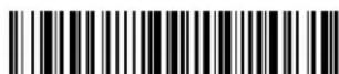
KBDCTY25.
Romania

KBDCTY26.
Russia

KBDCTY67.
Russian (MS)

KBDCTY68.
Russian (Typewriter)
Keyboard Countries (Continued)



Keyboard Countries (Continued)






Keyboard Style
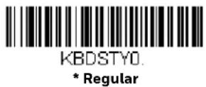
This programs keyboard styles, such as Caps Lock and Shift Lock. If you have used Keyboard Conversion settings, they will override any of the following Keyboard Style settings. Default = Regular.
Regular is used when you normally have the Caps Lock key off.
Caps Lock is used when you normally have the Caps Lock key on.

Shift Lock is used when you normally have the Shift Lock key on (not common to U.S. keyboards).

Automatic Caps Lock is used if you change the Caps Lock key on and off. The software tracks and reflects if you have Caps Lock on or off. This selection can only be used with systems that have an LED that notes the Caps Lock status (AT keyboards).

Autocaps via NumLock bar code should be scanned in countries (e.g., Germany, France) where the Caps Lock key cannot be used to toggle Caps Lock. The NumLock option works similarly to the regular Autocaps, but uses the NumLock key to retrieve the current state of the Caps Lock.

Emulate External Keyboard should be scanned if you do not have an external keyboard (IBM AT or equivalent).

Note: After scanning the Emulate External Keyboard bar code, you must power cycle your computer.
Keyboard Conversion
Alphabetic keyboard characters can be forced to be all upper case or all lowercase. So if you have the following bar code: "abc569GK," you can make the output "ABC569GK" by scanning Convert All Characters to Upper Case, or to "abc569gk" by scanning Convert All Characters to Lower Case.
These settings override Keyboard Style selections.
Note: If your interface is a keyboard wedge, first scan the menu code for Automatic Caps Lock (page 31). Otherwise, your output may not be as expected.
Default = Keyboard Conversion Off.

KBDCNVO
* Keyboard Conversion Off

KBDCNV1
Convert All Characters to Upper Case

KBDCNV2
Convert All Characters to Lower Case
Control Character Output
This selection sends a text string instead of a control character. For example, when the control character for a carriage return is expected, the output would display [CR] instead of the ASCII code of OD. Refer to ASCII Conversion Chart (Code Page 1252) on page 330. Only codes 00 through 1F are converted (the first column of the chart). Default = Off.
Note: Control + X (Control + ASCII) Mode overrides this mode.

KBDNPE1
Control Character Output On

KBDNPEO
* Control Character Output Off
Keyboard Modifiers
This modifies special keyboard features, such as CTRL+ ASCII codes and Turbo Mode.
Control + X (Control + ASCII) Mode On: The scanner sends key combinations for ASCII control characters for values 00-1F. Windows is the preferred mode. All keyboard country codes are supported. DOS mode is a legacy mode, and it does not support all keyboard country codes. New users should use the Windows mode.
Refer to ASCII Conversion Chart (Code Page 1252), page 330 for CTRL+ X Values.
Windows Mode Prefix/Suffix Off: The scanner sends key combinations for ASCII control characters for values 00-1F, but it does not translate prefix or suffix information.
Default = Control + X Mode Off.
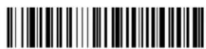
KBDCAS2
Windows Mode Control + X
Mode On

KBDCASO.
* Control + X Mode Off

KBDCAS1.
DOS Mode Control + X Mode On

KBDCAS3
Windows Mode Prefix/Suffix
Turbo Mode: The scanner sends characters to a terminal faster. If the terminal drops characters, do not use Turbo Mode. Default = Off.

KBDTMD1
Turbo Mode On
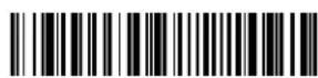
KBDTMDO
* Turbo Mode Off
Numeric Keypad Mode: Sends numeric characters as if entered from a numeric keypad. Default = Off.

KBDNPS1
Numeric Keypad Mode On
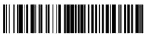
KBDNPSO
* Numeric Keypad Mode Off
Automatic Direct Connect Mode: This selection can be used if you have an IBM AT style terminal and the system is dropping characters. Default = Off.

KBDADC1
Automatic Direct Connect
Mode On

KBDADCO.
* Automatic Direct Connect Mode Off
RS232 Modifiers
RS232 Baud Rate
Baud Rate sends the data from the scanner to the terminal at the specified rate. The host terminal must be set for the same baud rate as the scanner. Default = 115,200.
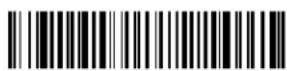
232BADO.
300

232BAD1.
600

232BAD2.
1200

232BAD3.
2400




RS232 Word Length: Data Bits, Stop Bits, and Parity
Data Bits sets the word length at 7 or 8 bits of data per character. If an application requires only ASCII Hex characters 0 through 7F decimal (text, digits, and punctuation), select 7 data bits. For applications that require use of the full ASCII set, select 8 data bits per character. Default = 8.
Stop Bits sets the stop bits at 1 or 2. Default = 1.
Parity provides a means of checking character bit patterns for validity. Default = None.



7 Data, 2 Stop Parity None

7 Data, 2 Stop, Parity Even
232WRD5
8 Data, 1 Stop, Parity Even
232WRD7
7 Data, 2 Stop, Parity Odd
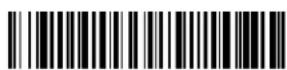
232WRD8
8 Data, 1 Stop, Parity Odd

232WRD2
* 8 Data, 1 Stop, Parity None

232WRD14
8 Data, 1 Stop, Parity Mark
RS232 Receiver Time-Out
The unit stays awake to receive data until the RS232 Receiver Time-Out expires. A manual or serial trigger resets the time-out. When an RS232 receiver is sleeping, a character may be sent to wake up the receiver and reset the time-out. A transaction on the CTS line will also wake up the receiver. The receiver takes 300 milliseconds to completely come up. Change the RS232 receiver time-out by scanning the bar code below, then scanning digits from the Programming Chart, beginning on page 341, then scanning Save. The range is 0 to 300 seconds. Default = 0 seconds (no time-out - always on).

232LPT
RS232 Receiver Time-Out
RS232 Handshake
RS232 Handshaking allows control of data transmission from the scanner using software commands from the host device. When RTS/CTS is turned Off, no data flow control is used.
Flow Control, No Timeout: The scanner asserts RTS when it has data to send, and will wait indefinitely for CTS to be asserted by the host.
Two-Direction Flow Control: The scanner asserts RTS when it is OK for the host to transmit. The host asserts CTS when it is OK for the device to transmit.
Flow Control with Timeout: The scanner asserts RTS when it has data to send and waits for a delay (see RS232 Timeout on page 37) for CTS to be asserted by the host. If the delay time expires and CTS is not asserted, the device transmit buffer is cleared and scanning may resume. Default = RTS/CTS Off.

Flow Control, No Timeout

Two-Direction Flow Control

Flow Control with Timeout

* RTS/CTS Off
RS232 Timeout
When using Flow Control with Timeout, you must program the length of the delay you want to wait for CTS from the host. Set the length (in milliseconds) for a timeout by scanning the bar code below, then setting the timeout (from 1-5100 milliseconds) by scanning digits from the Programming Chart, beginning on page 341, then scanning Save.

232DEL.
RS232 Timeout
XON/XOFF
Standard ASCII control characters can be used to tell the scanner to start sending data (XON/XOFF On) or to stop sending data (XON/XOFF Off). When the host sends the XOFF character (DC3, hex 13) to the scanner, data transmission stops. To resume transmission, the host sends the XON character (DC1, hex 11). Data transmission continues where it left off when XOFF was sent. Default = XON/XOFF Off.
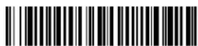
232XON1
XON/XOFF On

232XONO
* XON/XOFF Off
ACK/NAK
After transmitting data, the scanner waits for an ACK character (hex 06) or a NAK character (hex 15) response from the host. If ACK is received, the communications cycle is completed and the scanner looks for more bar codes. If NAK is received, the last set of bar code data is retransmitted and the scanner waits for ACK/NAK again. Turn on the ACK/NAK protocol by scanning the ACK/NAK On bar code below. To turn off the protocol, scan ACK/NAK Off. Default = ACK/NAK Off.

232ACK1
ACK/NAK On

232ACK0
* ACK/NAK Off
Scanner to Bioptic Communication
The following settings are used to set up communication between Honeywell scanners and bioptic scanners.
Note: The scanner's baud rate must be set to 38400 and the RS232 timeout must be set to 3000 in order to communicate with a bioptic scanner. See "RS232 Modifiers" on page 34, and RS232 Timeout on page 37 for further information.
Scanner-Bioptic Packet Mode
Packet Mode On must be scanned to set the scanner's format so it is compatible with a bioptic scanner. Default = Packet Mode Off.
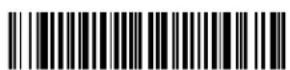
232PKTO
* Packet Mode Off

232PKT2.
Packet Mode On
Scanner-Bioptic ACK/NAK Mode
Bioptic ACK/NAK On must be scanned so the scanner will wait for an ACK or NAK from a bioptic scanner after each packet is sent. The Scanner-Bioptic ACK/NAK Timeout (below) controls how long the scanner will wait for a response. Default = Bioptic ACK/NAK Off.

232NAKO.
* Bioptic ACK/NAK Off

232NAK1
Bioptic ACK/NAK On
Scanner-Bioptic ACK/NAK Timeout
This allows you to set the length (in milliseconds) for a timeout for a bioptic scanner's ACK/NAK response. Scan the bar code below, then set the timeout (from 1-30,000 milliseconds) by scanning digits from the Programming Chart, beginning on page 341, then scanning Save. Default = 5100.

232DLK.
ACK/NAK Timeout
Note: This chapter does not apply to corded or Xenon 1902g-BF scanners. See Cordless System Operation: Xenon 1902g-BF beginning on page 79 for Xenon 1902g-BF scanning systems.
How the Cordless Charge Base/Access Point Works
A cordless charge base or an Access Point provide the link between the cordless scanner and the host system. The base/Access Point contains an interface assembly and an RF communication module. The RF communication module performs the data exchange between the cordless scanner and the interface assembly. The control assembly coordinates the central interface activities including: transmitting/receiving commands and data to/from the host system, performing software activities (parameter menuing, visual indicator support, power-on diagnostics), and data translation required for the host system.
The cordless charge base is also a scanner's battery charger. Refer to Charge Information, page 47, for additional information.
Link the Scanner to a Charge Base
Turn off power before connecting a base, then power up the computer once the base is fully connected. When the base is connected and powered up, put the scanner in the base to establish a link. The green LED on the base flashes to indicate the scanner's battery is charging.
If the scanner and base have previously been linked, you do not receive any feedback. If this is the first time that the scanner and base are linked, both devices emit a short chirp when their radios link. At this point, that one scanner is linked to one base.

To determine if your cordless system is set up correctly, scan one of the sample bar codes in the back of this manual. If the scanner provides a single good read beep and the green LED lights, the scanner has successfully linked to the base. If using a Granit scanner, the scanner also vibrates. If you receive an error tone and the red LED lights, the scanner has not linked to the base. Refer to page 325 for troubleshooting information.
Link the Scanner to an Access Point
Turn on the computer (laptop/desktop). Plug the interface cable into the Access Point first and then into the appropriate port on the computer. The Page button lights up when the connection to the host is made.
Scan the linking bar code on the top of the Access Point to establish a connection between the Access Point and the scanner. The scanner emits a short beep and flashes the green LED to confirm a connection with the Access Point. The Access Point's Page button remains blue.

Replace a Linked Scanner
If you need to replace a broken or lost scanner that is linked to a base or an Access Point, scan the Override Locked Scanner bar code below with a new scanner and place that scanner in the base, or scan the Access Point linking bar code. The locked link will be overridden; the broken or lost scanner's link with the base or Access Point will be removed, and the new scanner will be linked.

BT_RPL1.
Override Locked Scanner (Single Scanner)
Communication Between the Cordless System and the Host
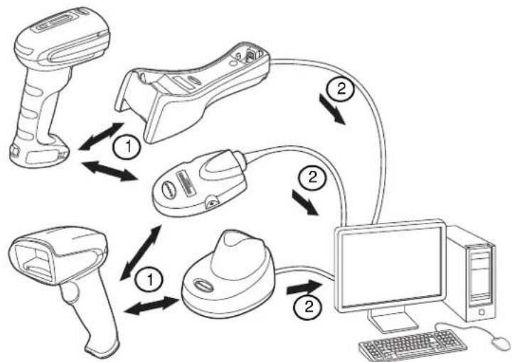
The cordless scanner provides immediate feedback in the form of a “good read” indication with a green LED on the scanner and an audible beep. If using a Granit scanner, the scanner also vibrates. This indicates that the bar code has been scanned correctly and the base or Access Point has acknowledged receiving the data. This is possible since the cordless system provides two-way communication between the scanner and the base or Access Point.
When data is scanned, the data is sent to the host system via the base or Access Point. The cordless scanner recognizes data acknowledgment (ACK) from the base or Access Point. If it cannot be determined that the data has been properly sent to the base or Access Point, the scanner issues an error indication. You must then check to see if the scanned data was received by the host system.
flowchart
graph TD
    A["Barcode scanner"] -->|①| B["Scan device"]
    B -->|②| C["Computer"]
    C -->|②| D["Printer"]
    D -->|①| E["Scaler"]
    E -->|①| F["Monitor"]
- Scanner reads code and gets ACK from base or Access Point
- Base or Access Point sends data to host
Program the Scanner and Base or Access Point
When using the scanner and charge base or Access Point together as a system, menu parameters and configuration settings are stored in the charge base or Access Point. Therefore, when programming any menu configuration settings, the scanner must be linked to the intended charge base or Access Point.
Note: This only applies when the scanner is linked to a charge base or Access Point. If the scanner is in a non-base mode, configuration settings are stored in the scanner.
RF (Radio Frequency) Module Operation
The cordless system uses a two-way Bluetooth ^® radio to transmit and receive data between the scanner and the base or Access Point. Designed for point-to-point and multi-point-to-single point applications, the radio operates using a license free ISM band, which sends relatively small data packets at a fast data rate over a radio signal with randomly changing frequencies, makes the cordless system highly responsive to a wide variety of data collection applications and resistant to noisy RF environments. The CCB01-010BT (Bluetooth Class 2) provides a communication range of 33 feet (10m) between the scanner and base or Access Point, depending on the environment. The CCB02-100BT/CCB05-100BT (Bluetooth Class 1) provides a communication range of 330 feet (100m) between the scanner and base or Access Point, depending on the environment. See Flexible Power Management, page 58, for information about controlling this range.
System Conditions
The components of the cordless system interact in specific ways as you associate a scanner to a base or Access Point, as you move a scanner out of range, bring a scanner back in range, or swap scanners between two cordless systems. The following information explains the cordless system operating conditions.
Link Process
Once a scanner is placed into a cordless charge base, the scanner's battery charge status is checked, and software automatically detects the scanner and links it to the base depending on the selected link mode.
Refer to Link the Scanner to an Access Point, page 42, for information about linking to an Access Point.
Scanner Is Out of Range
The cordless scanner is in communication with its base or Access Point, even when it is not transmitting bar code data. Whenever the scanner can't communicate with the base or Access Point for a few seconds, it is out of range. If the scanner is out of
44 Xenon/Granit User Guide
range and you scan a bar code, the scanner issues an error tone indicating no communication with the base or Access Point. A cordless charge base can also sound an alarm. Refer to Out-of-Range Alarm, page 56.
Scanner Is Moved Back Into Range
The scanner relinks if the scanner or the base or Access Point have been reset, or the scanner comes back into range. If the scanner relinks, you will hear a single chirp when the relinking process (uploading of the parameter table) is complete. Refer to Out-of-Range Alarm on page 56 for further information.
Out of Range and Back into Range with Batch Mode On
The scanner may store a number of symbols (approximately 500 U.P.C. symbols; others may vary) when it is out of range and then send them to the base or Access Point when back in range (see Batch Mode on page 59).
You will not hear a communication error tone in this mode, but you will hear a short buzz when you pull the trigger if the radio communication is not working. Once the radio connection is made, the scanner produces a series of beeps while the data is being transferred to the base or Access Point.
Page Button
When you press the Page button on the base or Access Point, the scanners associated with that base or Access Point will begin beeping (3 short and 1 long beep). If you pull the trigger on a scanner that is beeping in response, or press the Page button on the base or Access Point a second time, all associated scanners will stop beeping. See Page on page 51 for further information about Page Button settings.
Note: If you are using a Xenon 1902h model, refer to Quiet Operations - LED and Volume Settings on page 145 for additional Page Button settings.
Page Button and Presentation Modes

natural_image
Line drawing of a handheld scanner with a curved arrow indicating motion (no text or symbols)
When in Streaming Presentation Mode, the scanner's aimer goes out after a short time, but the scan illumination remains on all the time to continuously search for bar codes (see Streaming Presentation™ Mode on page 124). When in Temporary Streaming Presentation Mode, pressing the page button on the base puts the scanner into Streaming Presentation Mode until the timeout occurs. If a bar code is scanned before the timeout is reached, the timer starts over.
When the scanner is in the base, press the page button once to put the scanner into Temporary Streaming Presentation Mode. When the scanner is in the base and the base has external power (plugged into an outlet), press the page button twice to put the scanner into Streaming Presentation Mode. Press it twice again to end Streaming Presentation Mode. When the base does not have external power, pressing the page button twice does not trigger Streaming Presentation Mode.
When the scanner is out of the base, the page button works normally. Default = Temporary Streaming Presentation Mode On.

To remove Temporary Streaming Presentation Mode, scan the bar code for * Page Mode On on page 52.
Temporary Streaming Presentation Timeout
Set a timeout for the length of time the illumination remains on and searching for bar codes when using Temporary Streaming Presentation Mode. Set the length for the timeout by scanning one of the bar codes below. Default = 10,000 ms (10 seconds).

About the Battery

Warning: There is a danger of explosion if the batteries are incorrectly replaced. Replace the batteries with only the same or equivalent type recommended by the manufacturer. Dispose of used batteries according to the recycle program for batteries as directed by the governing agency for the country where the batteries are to be discarded.
Power is supplied to the cordless scanner by a rechargeable battery that is integrated in the scanner handle. Batteries are shipped only partially charged. The battery should be charged for a minimum of 4 hours before initial use to ensure optimal performance.
The battery is designed to charge while the scanner is positioned in the cordless base unit. Refer to Base/Access Point LED Sequences and Meaning, page 49, for an interpretation of the Charge Status indicators. Refer to Charge Only Mode (page 54) if you need to charge a scanner without linking it to the base.
Place the scanner in the base that is connected to an appropriate power supply. Use only a Listed Limited Power Source (LPS) or Class 2 type power supply with output rated 5 to 5.2Vdc, 1A.
Note: If you are powering the base through the interface cable (for example, a USB cable) and not using an external power supply plugged into the aux port, the current available for charging is reduced and charge times are increased.
Battery Recommendations
- The battery is a lithium ion cell and can be used without a full charge, and can also be charged without fully discharging, without impacting the battery life. There is no need to perform any charge/discharge conditioning on this type of battery.
- Keep the base connected to power when the host is not in use.
- Replace a defective battery immediately since it could damage the scanner.
- Although your battery can be recharged many times, it will eventually be depleted. Replace it after the battery is unable to hold an adequate charge.
- If you are not sure if the battery or charger is working properly, send it to Honeywell International Inc. or an authorized service center for inspection. Refer to Customer Support on page xvii for additional information.

Caution: Use only Honeywell Li-ion battery packs, model number BAT-SCN01, rated 3.7 Vdc, 7.4Whr in this device. Use of any non-Honeywell battery may result in damage not covered by the warranty.
Safety Precautions for Lithium Batteries
- Do not place batteries in fire or heat the batteries.
- Do not store batteries near fire or other high temperature locations.
- Do not store or carry batteries together with metal objects.
- Do not expose batteries to water or allow the batteries to get wet.
- Do not connect (short) the positive and negative terminals, of the batteries, to each other with any metal object.
- Do not pierce, strike or step on batteries or subject batteries to strong impacts or shocks.
- Do not disassemble or modify batteries.

Caution: Danger of explosion if batteries are incorrectly replaced. Dispose of used batteries according to the recycle program for batteries as directed by the governing agency for the country where the batteries are to be discarded.
Proper Disposal of the Battery

When the battery has reached the end of its useful life, the battery should be disposed of by a qualified recycler or hazardous materials handler. Do not incinerate the battery or dispose of the battery with general waste materials. You may send the scanner's battery to us. (postage paid). The shipper is responsible for complying with all federal, state, and local laws and regulations related to the packing,
labeling, manifesting, and shipping of spent batteries. Contact the Product Service Department (page xvii) for recycling or disposal information. Since you may find that your cost of returning the batteries significant, it may be more cost effective to locate a local recycle/disposal company.
Beeper and LED Sequences and Meaning
The scanner contains LEDs on the rear of the unit that indicate linking status, decoding state, and battery condition. The base has LEDs on the top of the unit that indicate its power up, communication, and battery charge condition. The red
LED = error; green LED = success of any type. Scanners and the CCB01-010BT base have audible indicators as well: 1 razz or error tone = error; 2 beeps = menu change; 1 beep = all other successes.
The table below lists the indication and cause of the LED indication, beeps, and vibrations for the scanner.
Scanner LED Sequences and Meaning
| LED Indication | Beeper Indication | Vibrate Indication | Cause |
| Normal Operation | |
| Red Flash None None | Battery low | | |
| Green Flash 1 beep | None Successful communication or | | linking |
| Red, blinking Razz or | error tone None Failed | communication | |
| Menu Operation | |
| Green Flash 2 beeps | 2 vibrations Successful menu change | | |
| Red, blinking Razz or | error tone 1 long vibration | Unsuccessful menu change | |
Base/Access Point LED Sequences and Meaning
The base contains a red LED and the Access Point has a blue LED that indicate the status of the unit and verifies its communication with the host system. The base also has a green LED that indicates scanner battery charge condition.
| Red or Blue LED - Host Communication |
| Red or Blue LED Communication Condition | |
| Off | USB suspend |
| On continuously | Power on, system idle |
| Short blinks in multiple pulses. Occurs while transferring data to/from the RF module or the Host port. | Receiving data |
| Green LED - Scanner Battery(base only, does not apply to Access Point) |
| Green LED | Charge Condition |
| Off | Battery not detected or chargesuspended |
| Slow flash, 1 second on, 1 second off | Pre-charge and charging |
| On continuously | Charge complete |
| Fast flash, 300 mSec on, 300 mSec off | Charge Error |
Base Power Communication Indicator
To display the power indicator on a base or an Access Point, scan the Base Power Communication Indicator On bar code. To turn off the power indicator, scan the Off bar code. Default = On.
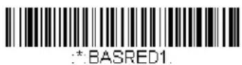
* Base Power Communication Indicator On

*.BASREDO
Base Power Communication Indicator Off
Reset Scanner
Scanning this bar code reboots the scanner and causes it to relink with the base or Access Point.

RESET
Reset Scanner
Scan While in Base Cradle
Note: This feature only applies to the CCB01-010BT base.
If you want to be able to scan bar codes while the scanner is in the base cradle, scan the Scan in Cradle On bar code below. If you want to only allow scanning when the scanner is out of the base cradle, scan Scan in Cradle Off. If you want the scanner to shut down when in the base cradle, scan Shut Down Scanner in Cradle. Default = Scan in Cradle On (for CCB01-010BT).

BT SICO.
Scan in Cradle Off

BT SIC1
* Scan in Cradle On

BT_SIC2.
Shut Down Scanner in Cradle
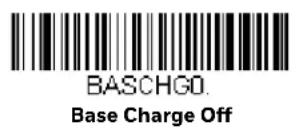
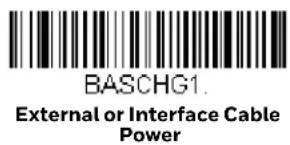
Base Charge Modes
When the base has both an external power supply (plugged into the auxiliary power port) and a host interface cable, it will draw its power from the external power supply. When the base does not have an external power supply, it draws its power from the interface cable. However, the scanner battery charges more slowly from a host interface cable than if auxiliary power were available. Using the following selections, you can specify whether the scanner battery is charged from power supplied via the host interface cable.
When Base Charge Off is selected, the scanner battery does not charge when the scanner is in the base cradle.
When External or Interface Cable Power is selected, the scanner battery charges from the base's external power supply, if there is one. If there is no external power supply to the base, the scanner battery charges from the interface cable.
When External Power Only is selected, the scanner battery only charges from the base's external power supply. If there is no external power supply, the scanner battery does not charge.
Note: If you are using a cordless charge base in Presentation Mode, External Power Only is the only setting available.
Default = External or Interface Cable Power.

Page
Page Mode
By default, the paging button on the base or Access Point pages the scanners associated with that base or Access Point. If you want the paging button on your base or Access Point to be disabled, scan the Page Mode Off bar code, below. When Page Mode is off, the base or Access Point will no longer page scanners when
the button is pressed. The red LED on the base or blue LED on the Access Point will remain lit to indicate that Page Mode is off. (This light will go out when the button is pressed, then back on when it's released.) Default = Page Mode On.
Note: If you are using a Xenon 1902h model, refer to Quiet Operations - LED and Volume Settings on page 145 for additional Page Button settings.

BEPPGE1
* Page Mode On

BEPPGEO
Page Mode Off
Page Pitch
When you press the Page button on the base or Access Point, the scanners associated with that base or Access Point will begin beeping (see Page Button on page 45). You can set the pitch of the paging beep for each scanner by scanning one of the following bar codes. Default = Low.
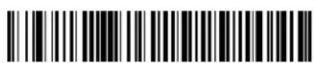
BEPPFQ1000
* Low (1000 Hz)

BEPPFQ3250
Medium (3250 Hz)

BEPPFQ4200
High (4200 Hz)
Error Indicators
Beeper Pitch - Base Error
Note: This feature only applies to the CCB01-010BT base.
The CCB01-010BT base can be configured to beep at a particular pitch when an error occurs, such as transmission problems to a host system. The beeper pitch codes modify the pitch (frequency) of the error tone the base emits when there is an error. Default = Low.
52 Xenon/Granit User Guide

BASFQ2250
* Razz (250 Hz)
BASFQ23250
Medium (3250 Hz)
BASFQ24200
High (4200 Hz)
Number of Beeps - Base Error
Note: This feature only applies to the CCB01-010BT base.
The number of beeps and LED flashes emitted by the CCB01-010BT base for an error condition can be programmed from 1 - 9. For example, if you program this option to have five error beeps, there will be five error beeps and five LED flashes in response to an error. To change the number of error beeps, scan the bar code below and then scan a digit (1-9) from the Programming Chart, beginning on page 341, then Save. Default = 1.
BASERR
Number of Base Error Beeps/LED Flashes
Scanner Report
Scan the bar code below to generate a report for the connected scanners. The report indicates the port, work group, scanner name, and address. To assign a name to your scanner, refer to Menu Command Syntax, page 259.

RPTSCN
Scanner Report
Scanner Address
Scan the bar code below to determine the address of the scanner you are using.

BT LDA
Scanner Address
Base or Access Point Address
Scan the bar code below to determine the address of the base or Access Point you are using.

*: BASLDA.
Base Address
Scanner Modes
Your scanner is capable of working in single scanner mode, multiple scanner mode, or with Bluetooth devices other than the charge base or Access Point.
Charge Only Mode
There may be times when you want to charge your scanner, but not link to the base. For example, if a scanner is linked to an Access Point or other Bluetooth device and you need to charge the scanner, but want to retain your existing link.
In order to program the base for Charge Only Mode, you must link a scanner to it. Once the scanner is linked to the base, scan the Charge Only Mode bar code. Any subsequent scanners placed in that base will charge without linking to it. The scanner used to program the base remains linked to the base. To unlink this scanner, scan Unlink Scanner on page 55.

*:BASLNKO
Charge Only Mode
Note: When in Charge Only Mode, the scanner periodically wakes up and beeps. See "Power Up Beeper" on page 5-111 to change this setting.
Charge and Link Mode
If you want to charge a scanner and link to the base, use Charge and Link Mode. If the base is programmed for Charge Only Mode, you must link a scanner to it first in order to program it for Charge and Link Mode. Scan the linking bar code on the base to link the scanner, then scan Charge and Link Mode. Default = Charge and Link Mode.

*:BASLNK1
* Charge and Link Mode
Linked Modes
Locked Link Mode and Open Link Mode are the link modes that accommodate different applications. Scan the appropriate bar codes included in the Open Link and Locked Link Mode explanations that follow to switch from one mode to another. Default = Open Link Mode.
Locked Link Mode - Single Scanner
If you link a scanner to a base or an Access Point using the Locked Link Mode, other scanners are blocked from being linked if they are inadvertently placed into the base, or if the Access Point linking bar code is scanned. If you do place a different scanner into a base, it will charge the scanner, but the scanner will not be linked.
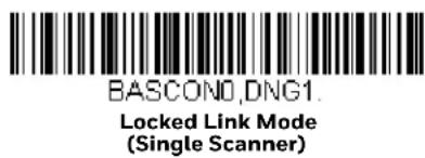
To use a different scanner, you need to unlink the original scanner by scanning the Unlink Scanner bar code. (See Scanner Modes, page 54.)
Open Link Mode - Single Scanner
When newly shipped or defaulted to factory settings, a scanner is not linked to a base or an Access Point. A link is established when the scanner is placed into a base, or an Access Point linking bar code is scanned. When in Open Link Mode, a new link is established when a new scanner is placed in the base, or you scan an Access Point linking bar code. Each time a scanner is placed into a base or scans an Access Point linking bar code, the scanner becomes linked to the base or Access point and the old scanner is unlinked.

Unlink the Scanner
If a base or an Access Point has a scanner linked to it, that scanner must be unlinked before a new scanner can be linked. Once the previous scanner is unlinked, it will no longer communicate with the base or Access Point. To unlink the scanner from a base or an Access Point, scan the Unlink Scanner bar code below.

Override Locked Scanner
If you need to replace a broken or lost scanner that is linked to a base or an Access Point, scan the Override Locked Scanner bar code below with a new scanner and place that scanner in the base, or scan the Access Point linking bar code. The locked link will be overridden; the broken or lost scanner's link with the base or Access Point will be removed, and the new scanner will be linked.

BT_RPL1.
Override Locked Scanner
(Single Scanner)
Out-of-Range Alarm
If your scanner is out range of the base, an alarm sounds from both your base and scanner. If your scanner is out range of an Access Point, an alarm sounds from just the scanner. The alarm stops when the scanner is moved closer to the base or Access Point, when the base or Access Point connects to another scanner, or when the alarm duration expires. To activate the alarm options for the scanner or the base and to set the alarm duration, scan the appropriate bar code below and then set the time-out duration (from 0-3000 seconds) by scanning digits on the Programming Chart, beginning on page 341, then Save. Default = 0 sec (no alarm).

BASORD
Base Alarm Duration
Note: The Access Point does not have a base alarm.

BT ORD
Scanner Alarm Duration
Note: If you are out of range when you scan a bar code, you will receive an error tone even if you do not have the alarm set. You receive the error tone since the data could not be communicated to the base or Access Point or the host.
Alarm Sound Type
You may change the alarm type for the scanner or a CCB01-010BT base by scanning the appropriate bar code below and then scanning a digit (0-7) bar code from the Programming Chart, beginning on page 341, then Save. Default = 0.
The sounds are as follows:
| Setting Sound |
| 0 3 long beeps, medium pitch |
| 1 3 long beeps, high pitch |
| 2 4 short beeps, medium pitch |
| 3 4 short beeps, high pitch |
| 4 single chirps, medium pitch |
| 5 2 chirps, then 1 chirp, medium pitch |
| 6 single chirps, high pitch |
| 7 2 chirps, then 1 chirp, high pitch |

BASORW.
Base Alarm Type
Note: Only the CCB01-010BT base has an alarm.

BT_ORW.
Scanner Alarm Type
Scanner Power Time-Out Timer
When there is no activity within a specified time period, the scanner enters low power mode. Scan the appropriate scanner power time-out bar code to change the time-out duration (in seconds).
Note: Scanning zero (0) is the equivalent of setting no time-out.
If there are no trigger pulls during the timer interval, the scanner goes into power down mode. Whenever the trigger is enabled, the timer is reset. If the scanner is placed in the charge base cradle and the battery is in the process of being charged, the scanner will not go into power down mode. Default = 3600 seconds.
BT LPTO
0 seconds

BT LPT200.
200 seconds

BT LPT400
400 seconds

BT LPT900
900 seconds

BT LPT3600
* 3600 seconds

BT LPT7200
7200 seconds
Note: When the scanner is in power down mode, pull the trigger to power the unit back up. There will be a set of power up beeps and a delay of up to a few seconds for the radio to join. The scanner will then be ready to use.
Flexible Power Management
If you are experiencing network performance issues, and suspect the scanner is interfering with other devices, you can turn down the power output of the scanner. This reduces the range between the scanner and a base or an Access Point as shown in the following illustration:

Scan one of the bar codes below to set the scanner's power output to Full Power (100%), Medium Power (35%), Medium Low Power (5%), or Low Power (1%). Default = Full Power.
Note: Setting a Granit scanner to anything lower than Full Power changes it to Class II Bluetooth.
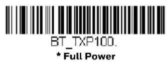
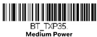

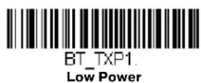
Batch Mode
Batch mode is used to store bar code data when a scanner is out of range of its base or Access Point, or when performing inventory. The data is transmitted to the base or Access Point once the scanner is back in range or when the records are manually transmitted.
Note: Batch Mode is only supported by the Honeywell Charge and Communication Base (CCB) and Honeywell Access Point (AP). Batch mode has limitations when using multiple scanners to one base or Access Point. If a cordless system is being used in “multiple link mode,” where up to 7 scanners are to be connected to one base or Access Point, some accumulated or batched scans could be lost if scanners are constantly being moved in and out of range.
Automatic Batch Mode stores bar code data when the scanner is out of range of the base or Access Point. The data is automatically transmitted to the base or Access Point once the scanner is back in range. When the scanner's buffer space is full, any bar codes scanned generate an error tone. In order to scan bar codes again, the scanner must be moved back into range of the base or Access Point so data can be transmitted.
Inventory Batch Mode stores bar code data, whether or not you are in range of the base or Access Point. To transmit the stored data to the base or Access Point, either place the scanner in the base, or scan Transmit Inventory Records (page 64). When
the scanner's buffer space is full, any bar codes scanned generate an error tone. In order to scan bar codes again, the data must be transmitted to the base or Access Point. Once the data is transmitted, it is cleared in the scanner.
Persistent Batch Mode is the same as Inventory Batch Mode, except that once the data is transmitted to the base or Access Point, it is retained in the scanner. If you want to transmit more than once, you can do so using this mode. In order to clear the scanner's buffer, you must scan Clear All Codes (see page 64).
Default = Batch Mode Off.
BATENAD
* Batch Mode Off

BATENA1
Automatic Batch Mode

BATENA2
Inventory Batch Mode
BATENA3
Persistent Batch Mode
Batch Mode Beep
When scanning in Inventory Batch Mode (page 60), the scanner beeps every time a bar code is scanned. If using a Granit scanner, it also vibrates. When Batch Mode Beep is On, you will also hear a click when each bar code is sent to the host. If you do not want to hear these clicks, scan Batch Mode Beep Off. Default = Batch Mode Beep On.

BATBEPO
Batch Mode Beep Off
BATBEP1
* Batch Mode Beep On
Batch Mode Storage
When a scanner is storing data during a Batch Mode process, you can select whether the data is stored in Flash memory or in RAM.
Flash Storage: The scanner writes any untransmitted data to flash memory prior to powering down. The data will still be there when the scanner powers back up. However, the scanner will power down, even with untransmitted data, if it reaches a power down timeout or if the battery power is very low.
RAM Storage: The scanner will not power down while it contains data that has not been transmitted to the base or Access Point, even if it reaches a power down time-out. However, if the scanner runs out of battery power, it will power down and the data will be lost.
Default = Flash Storage.

BATNVS1
* Flash Storage
BATNVSO
RAM Storage
Batch Mode Quantity
When in Batch Mode, you may wish to transmit the number of multiple bar codes scanned, rather than a single bar code multiple times. For example, if you scan three bar codes called XYZ with Batch Mode Quantity Off, when you transmit your data it will appear as XYZ three times. Using Batch Mode Quantity On and the Quantity Codes (page 63), you could output your data as "XYZ, 00003" instead.
Note: If you wish to format your output, for example, place a CR or tab between the bar code data and the quantity, refer to Data Format beginning on page 157.
Default = Batch Mode Quantity Off.

BATQTY0.
* Batch Mode Quantity Off

BATQTY1
Batch Mode Quantity On
Enter Quantities
Quantity Codes (page 63) allow you to enter a quantity for the last item scanned, up to 9999 (default = 1). Quantity digits are shifted from right to left, so if a 5th digit is scanned, the 1st digit scanned is discarded and the 2nd, 3rd and 4th digits are moved to the left to accommodate the new digit.
For example, if the Quantity 5 bar code is scanned after the quantity has been set to 1234, then the 1 is dropped, the quantity will be 2345.
Example: Add a quantity of 5 for the last item scanned.
- Scan the item's bar code.
- Scan the quantity 5 bar code.
Example: Add a quantity of 1,500 for the last item scanned.
- Scan the item's bar code.
- Scan the quantity 1 bar code.
- Scan the quantity 5 bar code.
- Scan the quantity 0 bar code.
- Scan the quantity 0 bar code.
Example: Change a quantity of 103 to 10.
To correct an incorrect quantity, scan the quantity 0 bar code to replace the incorrect digits, then scan the correct quantity bar codes.
- Scan the quantity 0 bar code to change the quantity to 1030.
- Scan the quantity 0 bar code to change the quantity to 0300.
- Scan the quantity 1 bar code to change the quantity to 3001.
- Scan the quantity 0 bar code to change the quantity to 0010.
Default = 1.
Quantity Codes


Quantity Codes (Continued)



Batch Mode Output Order
When batch data is transmitted, select whether you want that data sent as FIFO (first-in first-out), or LIFO (last-in first-out). Default = Batch Mode FIFO.


Total Records
If you wish to output the total number of bar codes scanned when in Batch Mode, scan Total Records.

BATNRC.
Total Records
Delete Last Code
If you want to delete the last bar code scanned when in Batch Mode, scan Delete Last Code.
BATUND.
Delete Last Code
Clear All Codes
If you want to clear the scanner's buffer of all data accumulated in Batch Mode, scan Clear All Codes.
BATCLR.
Clear All Codes
Transmit Records to Host
If you are operating in Inventory Batch Mode (see Inventory Batch Mode on page 60), you must scan the following bar code to transmit all the stored data to the host system.

BAT_TX
Transmit Inventory Records
Batch Mode Transmit Delay
Sometimes when accumulated scans are sent to the host system, the transmission of those scans is too fast for the application to process. To program a transmit delay between accumulated scans, scan one of the following delays. Default = Off.
Note: In most cases, a short (250 ms (milliseconds)) delay is ideal, however, longer delays may be programmed. Contact Technical Support (page xvii) for additional information.

BATDLYO
* Batch Mode Transmit Delay Off (No Delay)
BATDLY250
Batch Mode Transmit Delay Short (250 ms)

BATDLY500.
Batch Mode Transmit Delay Medium (500 ms)

BATDLY1000
Batch Mode Transmit Delay Long (1000 ms)
Multiple Scanner Operation
Note: Multiple Scanner Operation Mode allows you to link up to 7 scanners to one base or Access Point. You cannot join an 8th scanner until you unlink one of the 7 scanners or take a scanner out of range.
To put the scanner in multiple scanner mode, scan the bar code below. Once you scan this bar code, the scanner is unlinked from the base or Access Point and must either be placed into the base, or you must scan the Access Point linking bar code in order to relink.

BASCON2.DNG3
Multiple Scanner Operation
Scanner Name
You may assign a name to each scanner you are using for identification purposes. For example, you may want to have a unique identifier for a scanner that is receiving imaging commands sent from the base or Access Point.
The default name is in the format "ScannerName_Model_SN_XXXXXXXXXX" If you have more than one scanner linked to a base, and they all have the same name, the first scanner linked to the base receives commands. When renaming a series of scanners with identical names, unlink all except one of the scanners from the base.
Perform the rename operation using either the bar codes on page 67, or by sending the serial command :ScannerName:BT_NAMNewName. where ScannerName is the current name of the scanner, and NewName is the new name for the scanner. If you wish to change the names of additional scanners, link them one at a time and repeat the :ScannerName:BT_NAMNewName. command for each scanner.
To rename scanners with sequential, numeric names, scan the bar codes below. Scan the Reset code after each name change and wait for the scanner to relink to the base or Access Point before scanning a bar code to rename the next scanner.

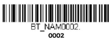


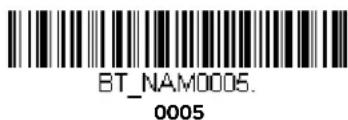


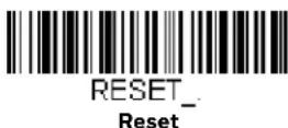
You may also scan the Scanner Name bar code below and scan a number for the scanner name. For example, if you wanted to name the linked scanner "312," you would scan the bar code below, scan the 3, 1, and 2 bar codes on the Programming Chart, beginning on page 341, then Save. Scan the Reset bar code and wait for the scanner to relink to the base.

BT NAM
Scanner Name
Application Work Groups
Your cordless system can have up to 7 scanners linked to one base or Access Point. You can also have up to 7 work groups. If you want to have all of the scanners' settings programmed alike, you don't need to use more than 1 work group. If you want each scanner to have unique settings (e.g., beeper volume, prefix/suffix, data formatter), then you may program each scanner to its own unique work group and may program each scanner independently. For example, you might want to have multiple work groups in a retail/warehouse application where you need to have different data appended to bar codes used in the warehouse area versus the retail area. You could assign all the scanners in the retail area to one work group and those in the warehouse to another. Consequently, any desired changes to either the retail or warehouse area would apply to all scanners in that particular work group. Honeywell's online configuration tool, EZConfig-Scanning (page 254), makes it easy for you to program your system for use with multiple scanners and multiple work groups.
The scanner keeps a copy of the menu settings it is using. Whenever the scanner is connected or reconnected to a base or an Access Point, the scanner is updated with the latest settings from the base or Access Point for its work group. The scanner also receives menu setting changes processed by the base or Access Point. If a scanner is removed from a base or an Access Point and placed into another base or linked to another Access Point, it will be updated with the new base/Access Point settings for whatever work group to which that the scanner was previously assigned. For example, if the scanner was in work group 1 linked to the first base, it will be placed in work group 1 in the second base with the associated settings.
Application Work Group Selection
This programming selection allows you to assign a scanner to a work group by scanning the bar code below. You may then program the settings (e.g., beeper volume, prefix/suffix, data formatter) that your application requires. Default = Group 0.

GRPSELO.
* Group 0
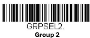


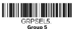
Reset the Factory Defaults: All Application Work Groups
The following bar code defaults all of the work groups to the factory default settings.

To see what the factory default settings are, refer to the table of Menu Commands, beginning on page 264. The standard product default settings for each of the commands are indicated by an asterisk (*).
Note: Scanning this bar code also causes both the scanner and the base or Access Point to perform a reset and become unlinked. The scanner must be placed in the base, or the Access Point linking bar code must be scanned to re-establish the link. Refer to Scanner Modes, page 54 for additional information.
If your scanner is in multiple scanner mode, you will hear up to 30 seconds of beeping while all scanners are relinked to the base or Access Point and the settings are changed.
Reset the Custom Defaults: All Application Work Groups
If you want the custom default settings restored to all of the work groups, scan the Custom Product Default Settings bar code below. (If there are no custom defaults, it will reset the work groups to the factory defaults.) See Set Custom Defaults on page 12 for further information about custom defaults.

PAPDFT.
Custom Default Settings: All Work Groups
Note: Scanning this bar code also causes both the scanner and the base or Access Point to perform a reset and become unlinked. The scanner must be placed in its base, or the Access Point linking bar code must be scanned to re-establish the link. Refer to Scanner Modes, page 54 for additional information.
If your scanner is in multiple scanner mode, you will hear up to 30 seconds of beeping while all scanners are relinked to the base or Access Point and the settings are changed.
Use the Scanner with Bluetooth Devices
The scanner can be used either with the charge base, an Access Point, or with other Bluetooth devices. Those devices include personal computers, laptops, PDAs, and Honeywell mobility systems devices.
Bluetooth Secure Simple Pairing (SSP)
Secure Simple Pairing (SSP) allows you to connect simply and securely to other Bluetooth devices without having to enter a PIN code (as described in Bluetooth HID Keyboard Connect procedure). SSP is only available when using Bluetooth version 2.1 or higher. When SSP is on, no PIN is required for pairing. Turn SSP off if you are connecting to a Bluetooth device that is not using a compatible Bluetooth version. Default = Bluetooth SSP On.
Note: SSP is only available with Granit 1981i scanner.

BT_SSP1.
* Bluetooth SSP On

BT_SSP0
Bluetooth SSP Off
Bluetooth HID Keyboard Connect
Your scanner can be paired with Bluetooth-capable devices, such as personal computers, laptops, and tablets, so that scanned data appears on your device screen as though it was entered on the keyboard. In order to pair with the Bluetooth device:
- Scan the appropriate Bluetooth HID Keyboard Connect bar code below.

PAPBTH.
Bluetooth HID Keyboard Connect
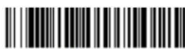
PAPJKB
Bluetooth HID Japanese Keyboard Connect
- Set your personal computer, laptop or tablet so it searches for other Bluetooth devices. (Refer to your device's User's Guide for pairing instructions.)
- Select the scanner name on your device. Some devices will automatically pair with the scanner. If your device pairs automatically with the scanner, it displays a successful pairing message and you do not need to continue to the next step.
- If your device does not automatically pair with the scanner, a PIN is displayed. This PIN must be scanned within 60 seconds. Quickly scan Bluetooth PIN Code below, then scan the numeric bar code(s) for the PIN code from the chart below, then scan Save.

BT_PIN
Bluetooth PIN Code

KOK
0
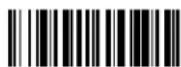
K1K
1

K2K
2

K3K
3

Virtual Keyboard
Once your scanner has been connected directly to an iPad, smart phone, or laptop, you can toggle the virtual keyboard on your device with a quick double pull of the scanner trigger.
Bluetooth HID Keyboard Disconnect
If your scanner has been connected directly to an iPad, smart phone, or laptop using Bluetooth HID Keyboard Connect (page 70), you must disconnect it in order to once again communicate with the base or Access Point. Scan the Bluetooth HID Keyboard Disconnect bar code to unlink the scanner from the currently linked host. Scan the linking bar code on the base or Access Point to relink the scanner.

PAPSPP
Bluetooth HID Keyboard Disconnect
Bluetooth Serial Port - PCs/Laptops
Scanning the Non-Base BT Connection bar code below unlinks your scanner and puts it into a discoverable state. Once the scanner searches for and connects with a Bluetooth host, the scanner stores the connection to the host device address and switches virtual COM ports. This allows the scanner to automatically relink to the host if the connection is lost.

BT_TRMO;BT_DNG5.
Non-Base BT Connection
PDAs/Mobility Systems Devices
You may also use the scanner with a PDA or a Honeywell Mobility Systems device. Scan the bar code below and follow the instructions supplied with your Bluetooth device to locate the scanner, and connect with it.

BT_TRMO;BT_DNG1.
BT Connection - PDA/Mobility Systems Device
Change the Scanner's Bluetooth PIN Code
Some devices require a PIN code as part of the Bluetooth security features. Your scanner's default PIN is 1234, which you may need to enter the first time you connect to your PDA or PC. The PIN code must be between 1 and 16 characters. To change the PIN, scan the bar code below and then scan the appropriate numeric bar codes from the Programming Chart, beginning on page 341, then Save.

BT_PIN.
Bluetooth PIN
Minimize Bluetooth/ISM Band Network Activity
The settings described below can help you customize the relinking behavior of the cordless area-imaging system to obtain the best compromise between convenience and low interference.
Note: ISM band refers to the 2.4 to 2.48 GHz frequency band used by wireless networks, cordless phones, and Bluetooth.
Auto Reconnect Mode
Auto Reconnect controls whether or not the scanner automatically begins the relink process when a loss of connection is detected. When the Auto Reconnect On bar code is scanned, the scanner begins the relink process immediately, without user intervention. Default = Auto Reconnect On.
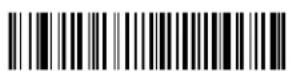
BT ACM1
* Auto Reconnect On
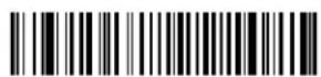
BT ACMO
Auto Reconnect Off
Note: If you are connecting to a Bluetooth Interface Module, set Auto Reconnect to Off. The table below shows the results of the Auto Reconnect On and Off settings:
| Event Auto Reconnect On | Auto Reconnect Off | |
| Scanner out of range Relink occurs automatically. If maximum number of link attempts is unsuccessful, then the scanner must be relinked by either pulling the trigger, placing the scanner in the base, or scanning the Access Point linking bar code. (See Maximum Link Attempts on page 73.) | The scanner is relinked by pulling the trigger, or scanning the Access Point linking bar code. |
| Base or Access point reset (firmware upgrade or power cycle) | Scanner behaves as if out of range. No attempt to relink made while base or Access Point is powered off. Trigger must be pulled to initiate relinking. |
| Scanner power down due to Power Time-Out Timer setting | Trigger must be pulled, Access Point linking bar code must be scanned, or the scanner must be placed in the base unit to relink. (Note: scanner relinks on power up, but powers on due to one of the above actions.) |
| Scanner reset due to firmware upgrade | Relink occurs automatically. |
| Scanner reset due to battery change | Relink occurs automatically. |
| Scanner placed in different base unit | Relink to new base occurs automatically. |
Maximum Link Attempts
The Maximum Link Attempts setting controls the number of times the scanner tries to form a connection with a base or an Access Point. During the connection setup process, the scanner transmits in order to search for and connect to a base
or an Access Point. In order to prevent continuous transmissions that could interfere with other users of the ISM band, the number of attempts to connect is limited by this setting. After the maximum number of attempts is reached, the scanner will not attempt to reconnect to a base or an Access Point. Pressing the trigger, scanning an Access Point linking bar code, or placing the scanner in the cradle resets the attempt count and the scanner will again try to link.
Scan the Maximum Link Attempts bar code, then scan the number of attempts for the setting (from 0-100) from the Programming Chart, beginning on page 341, then Save. Default = 0.

Note: When Auto Reconnect Mode is On, setting Maximum Link Attempts to zero will cause the scanner to try to link until the Power Time-Out Timer setting expires. When Auto Reconnect Mode is Off, setting Maximum Link Attempts to zero will cause the scanner to only attempt linking one time after a trigger pull.
Relink Time-Out
Relink Time-Out controls the idle time between relink attempts. An attempt to link a scanner to a base or an Access Point typically lasts up to 5 seconds. This is the time when the scanner is actually attempting a contact. Relink Time-Out controls the amount of time, in seconds, that elapses between the end of one connection attempt and the start of the next.
Note: The length of time for an attempt depends on the number of scanners connected to a base unit or Access Point. An extra 7 seconds may be required when a connection is successful.
Scan the Relink Time-Out bar code, then scan the number of seconds for the setting (from 1-100) from the Programming Chart, beginning on page 341, then Save. Default = 3 seconds.
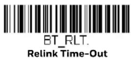
Bluetooth/ISM Network Activity Examples
Default values
When the scanner goes out of range, the scanner repeatedly attempts to connect to the base unit or Access Point. Each attempt consists of approximately 5 seconds of active time followed by 3 seconds of idle time. After one hour, the scanner powers off and batch mode data is lost.
Example: Maximum Link Attempts set to 15
Other values at default setting
When the scanner goes out of range, 15 attempts are made to link to the base unit or Access Point. Each attempt consists of approximately 5 seconds of active time followed by 3 seconds of idle time. After 15 cycles (8*15 =120), or about 2 minutes, the scanner stops trying to connect to the base or Access Point, but retains any bar codes that may have been saved in batch mode. After one hour, the scanner powers off and batch mode data is lost.
Example: Auto Reconnect Mode set to 0
Maximum Link Attempts set to 15
Other values at default setting
When the scanner goes out of range, no action is taken to relink. When the trigger is pulled, 15 attempts are made to link to the base or Access Point. Each attempt consists of approximately 5 seconds of active time followed by 3 seconds of idle time. After 15 cycles (8*15 =120), or about 2 minutes, the scanner stops trying to connect to the base or Access Point, but retains any bar codes that may have been saved in batch mode. After one hour, the scanner powers off and batch mode data is lost. Refer to Auto Reconnect Mode, page 73, to review other events that can start the relink process.
Example: Auto Reconnect Mode set to 1
Maximum Link Attempts set to 0
Relink Time-Out set to 10
Scanner Power Time-Out Timer set to 1800
Note: See Scanner Power Time-Out Timer on page 57.
The scanner attempts to connect to the base or Access Point every 15 seconds, measured from one attempt start to the next attempt start. After one half hour, the scanner powers off.
Host Acknowledgment
Some applications require that the host terminal (or server) validate incoming bar code data (database look-up) and provide acknowledgment to the scanner whether or not to proceed. In Host ACK Mode, the scanner waits for this acknowledgment after each scan. Visual and audible acknowledgments provide valuable
feedback to the scan operator. The Host ACK functionality is controlled via a number of pre-defined escape commands that are sent to the scanner to make it behave in different ways.
Note: System performance degrades when using Host ACK at rates lower than 9600 baud.
The following criteria must be met for the Host ACK to work correctly:
- The cordless system must be configured for Host Port RS232 (terminal ID = 000) or USB COM Emulation (terminal ID = 130).
- RTS/CTS is defaulted off. You must enable it if the host system requires it.
- Host ACK must be set to On (page 77).
- A comma must be used as a terminator.
- The host terminal software must be capable of interpreting the bar code data, make decisions based on the data content, and send out appropriate escape commands to the scanner.
Escape commands are addressed to the scanner via "Application Work Groups."
Once a command is sent, all scanners in a group respond to that command.
Because of this, it is recommended that each scanner is assigned to its own group in Host ACK mode.
The commands to which the scanner responds are listed on page 77. The [ESC] is a 1B in hex. A typical command string is y [ESC] x, where "y" is the application work group number, "[ESC] x" is the escape command, and the comma is the terminator, which is required. (When "y" is not specified, the command is sent to the default Application Work Group 0.)
Example: Commands may be strung together to create custom response sequences. An example of a command string is listed below.
[ESC]4,[ESC]5,[ESC]6,
The above example will make a scanner that is in application work group zero beep low, then medium, then high.
Example: A good read beep is required for any item on file, but a razz or error tone is required if the item is not on file. In this case,
[ESC]7, is sent from the host to the scanner for an on-file product
[ESC]8,[ESC]8, is sent from the host to the scanner for a not-on-file product
When a bar code is scanned, the scanner enters a timeout period until either the host ACK sequence is received, or the timeout expires (in 10 seconds, by default).
Once Host ACK is enabled, the system works as follows when a bar code is scanned:
- The scanner reads the code and sends data to the base or Access Point to transmit to the host system. No audible or visual indication is emitted until the scanner receives an escape command. The scanner read illumination goes out when there's a successful read.
- Scanner operation is suspended until 1) a valid escape string is received from the host system or 2) the scanner times out.
- Once condition 1 or 2 above has been met, the scanner is ready to scan again, and the process repeats.
A time-out occurs if the scanner does not receive a valid escape command within 10 seconds. A time-out is indicated by an error tone. If a time-out occurs, the operator should check the host system to understand why a response to the scanner was not received.
Host ACK On/Off

HSTACK1
Host ACK On

HSTACKO
* Host ACK Off
Host ACK Timeout
You can set a timeout for the length of time the scanner waits for a valid escape command when using Host Acknowledgment Mode. Set the length (in seconds) for a timeout by scanning the following bar code, then setting the timeout (from 1-90 seconds) by scanning digits from the Programming Chart, beginning on page 341, then Save. Default = 10.

HSTATO.
Host ACK Timeout
Host ACK Responses
| Command Action | |
| [ESC] a, Double beeps to indicate a successful menu change was made. |
| [ESC] b, Razz or error tone to indicate a menu change was unsuccessful. |
| [ESC] 1, The green LED illuminates for 135 milliseconds followed by a pause. |
| [ESC] 2, The green LED illuminates for 2 seconds followed by a pause. |
| [ESC] 3, The green LED illuminates for 5 seconds followed by a pause. |
| [ESC] 4, Emits a beep at a low pitch. |
| [ESC] 5, Emits a beep at a medium pitch. |
| [ESC] 6, Emits a beep at a high pitch. |
| [ESC] 7, Beeps to indicate | a successful decode and communication to host. |
| [ESC] 8,[ESC] 8, | Razz or error tone to indicate a decode/communication to host was unsuccessful. |
Note: This chapter applies only to Xenon 1902g-BF cordless scanning systems. It does not apply to corded scanners, Xenon 1902g/1912, or Granit 1911i/1981i scanners. See Cordless System Operation: Xenon 1902g/1912 and Granit 1911i/1981i beginning on page 41 for other Xenon and Granit cordless scanning systems.
How the CCB01-010BT-BF Cordless Charge Base Works
A cordless charge base provides the link between the cordless scanner and the host system. The base contains an interface assembly and an RF communication module. The RF communication module performs the data exchange between the cordless scanner and the interface assembly. The control assembly coordinates the central interface activities including: transmitting/receiving commands and data to/from the host system, performing software activities (parameter menuing, visual indicator support, power-on diagnostics), and data translation required for the host system.
The cordless charge base is also a scanner's instant charge pack charger. Refer to Charge Information, page 83, for additional information.
Link the Scanner to a Charge Base
Xenon Scanner

natural_image
Line drawing of a handheld scanner with a curved arrow pointing to the base (no text or symbols)
CCB01-010BT-BF Charge Base Page Button and Base LEDs
When the base is connected and powered up, put the scanner in the base to establish a link. The green LED on the base flashes to indicate the scanner's instant charge pack is charging.
Note: The scanner's instant charge pack must be charged to establish a link with the base.
If the scanner and base have previously been linked, you do not receive any feedback. If this is the first time that the scanner and base are linked, both devices emit a short chirp when their radios link. At this point, that one scanner is linked to one base.
The linking sound can be turned on or off. See Linking Sound on page 91.
To determine if your scanner has linked to the base correctly, scan one of the sample bar codes beginning on page 339. If the scanner provides a single good read beep and the green LED lights, the scanner has successfully linked to the base. If you receive an error tone and the red LED lights, the scanner has not linked to the base. Refer to page 325 for troubleshooting information.
Replace a Linked Scanner
If you need to replace a broken or lost scanner that is linked to a base, scan the Override Locked Scanner bar code below with a new scanner and place that scanner in the base. The locked link will be overridden, the broken or lost scanner's link with the base will be removed, and the new scanner will be linked.

Communication Between the Cordless System and the Host
The cordless scanner provides immediate feedback in the form of a “good read” indication with a green LED on the scanner and an audible beep. This indicates that the bar code has been scanned correctly and the base has acknowledged receiving the data. This is possible since the cordless system provides two-way communication between the scanner and the base.
When data is scanned, the data is sent to the host system via the base. The cordless scanner recognizes data acknowledgment (ACK) from the base. If it cannot be determined that the data has been properly sent to the base, the scanner issues an error indication. You must then check to see if the scanned data was received by the host system.
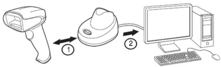
flowchart
graph LR
    A["Scan"] -->|①| B["Sensor"]
    B -->|②| C["Computer"]
- Scanner reads code and gets ACK from base.
- Base sends data to host.
Program the Scanner and Base
When using the scanner and charge base together as a system, menu parameters and configuration settings are stored in the charge base. Therefore, when programming any menu configuration settings, the scanner must be linked to the charge base.
Note: This only applies when the scanner is linked to a charge base. If the scanner is in a non-base mode, configuration settings are stored in the scanner.
RF (Radio Frequency) Module Operation
The cordless system uses a two-way, low energy, Bluetooth ^® radio to transmit and receive data between the scanner and the base. It provides single-point to single-point communication. The radio operates using a license free ISM band, which sends relatively small data packets at a fast data rate over a radio signal with randomly changing frequencies, makes the cordless system highly responsive to a wide variety of data collection applications and resistant to noisy RF environments.
The CCB01-010BT-BF (Bluetooth Class 2) provides a communication range of 33 feet (10m) between the scanner and base, depending on the environment. See Flexible Power Management, page 97, for information about controlling this range.
System Conditions
The components of the cordless system interact in specific ways as you associate a scanner to a base, as you move a scanner out of range and bring a scanner back in range. The following information explains the cordless system operating conditions.
Link Process
Once a scanner is placed into a cordless charge base, the scanner's instant charge pack status is checked, and software automatically detects the scanner and links it to the base depending on the selected link mode.
Scanner Is Out of Range
The cordless scanner is in communication with its base, even when it is not transmitting bar code data. Whenever the scanner can't communicate with the base for a few seconds, it is out of range. If the scanner is out of range and you scan a bar code, the scanner issues an error tone indicating no communication with the base. A cordless charge base can also sound an alarm. Refer to Out-of-Range Alarm, page 95.
Scanner Is Moved Back Into Range
The scanner relinks if the scanner or the base have been reset, or the scanner comes back into range. If the scanner relinks, you will hear a single chirp when the relinking process (uploading of the parameter table) is complete. Refer to Out-of-Range Alarm on page 95 for further information.
Out of Range and Back into Range with Batch Mode On
The scanner may store a number of symbols (approximately 500 U.P.C. symbols; others may vary) when it is out of range and then send them to the base when back in range (see Batch Mode on page 98).
You will not hear a communication error tone in this mode, but you will hear a short buzz when you pull the trigger if the radio communication is not working. Once the radio connection is made, the scanner produces a series of beeps while the data is being transferred to the base.
About the Instant Charge Pack
Power is supplied to the cordless scanner by a rechargeable instant charge pack that is integrated in the scanner handle. The instant charge pack must be charged before initial use. When the scanner is not in use, return it to the base. The model CCB01-010BT-BF base is designed for use with the Honeywell model Xenon 1902g-BF scanner.
The instant charge pack is designed to charge while the scanner is positioned in the cordless base unit. Refer to Base, page 86, for an interpretation of the Charge Status indicators. Refer to Charge Only Mode (page 93) if you need to charge a scanner without linking it to the base.
Place the scanner in the base that is connected to an appropriate power supply. Use only a Listed Limited Power Source (LPS) or Class 2 type power supply with output rated 5 to 5.2Vdc, 1A.

Caution: The Xenon 1902g-BF scanner can only be charged by CCB01-010BT-BF base. Use of any non-Honeywell power supply may result in damage not covered by the warranty.
Note: If you are powering the base through the interface cable (for example, a USB cable) and not using an external power supply plugged into the aux port, the current available for charging is reduced and charge times are increased. Charge times can be improved by connecting the interface cable to a BC 1.2 compliant USB charge port. Charging via the power supply is fastest.
The AC adapter should be plugged into the connector in the bottom of the base. Using the interface cable power link is not recommended and will significantly increase charge times.
Beeper and LED Sequences and Meaning
The scanner contains LEDs on the rear of the unit that indicate linking status, decoding state, and instant charge pack condition. The base has LEDs on the top of the unit that indicate its power up, communication, and instant charge pack condition.
Scanner
Scanner Communication and Scanning
The following feedback is provided by the scanner and indicates communication and scanning status.
| LED Indication Beeper Indication Cause | |
| Normal Operation | |
| Red Flash None Charge pack low | |
| Green Flash 1 beep Successful communication or linking | |
| Red, blinking Razz or error tone Failed communication | |
| Menu Operation | |
| Green Flash 2 beeps Successful menu change | |
| Red, blinking Razz or error tone Unsuccessful menu change | |
Scanner Charge Pack Status
The following charge status feedback is provided by the scanner when the scanner is out of the base and has been idle for 5 seconds.
| Scanner LED Scanner Beep | Charge Level | Approximate Expected Scans* |
| Yellow3 sets of flashes | 2 short beeps per flash 30% 100 | |
| Red3 sets of flashes | 2 short beeps per flash 10% 50 | |
* The number of scans was measured with a clearly printed UPC code in good light. The approximate number of scans varies with changes in label quality, symbology, and environmental factors.
Low Power Alerts
Low power alerts allow you to customize the scanner LEDs to flash in different patterns when the scanner charge level is low. Use the bar codes that follow to customize the settings for the power range being configured, the number of flashes per alert, the interval between flashes, the number of alerts, and the interval between alerts. The beeper can also be set to silent, or to sound with the flash patterns.
Low Power Alert Range
Set the power range that will trigger a low power alert. Default = 10-30%.

*Low Power Alert 10-30%

Low Power Alert Flash Number
You can program the scanner's LEDs to flash up to 9 times for the low power alert. If the Low Power Alert Beep (page 86) is on, a double beep will sound with each flash. To set the number of low power flashes, scan the bar code below and then scan a digit (1-9) bar code from the Programming Chart, beginning on page 341, then Save. Default = 3 flashes.

Low Power Alert Flash Number
Interval Between Flashes
Set the length of time, in seconds, between the LED flashes for a low power alert. To set the interval, scan the bar code below and then scan a digit (1-9) bar code from the Programming Chart, beginning on page 341, then Save. Default = 2 seconds between flashes.

Interval Between Flashes
Low Power Alert Repeat
Set how many times you want the low power flash pattern (flashes and intervals) to repeat. To set the number, scan the bar code below and then scan a digit (1-5) bar code from the Programming Chart, beginning on page 341, then Save. Default = 1.

Low Power Alert Repeat
Interval Between Alerts
If you have set the Low Power Alert Repeat (page 85) to more than 1, you can set the length of time, in seconds, between the low power alerts. To set this interval, scan the bar code below and then scan a digit (10-120) bar code from the Programming Chart, beginning on page 341, then Save. Default = 10 seconds between alerts.
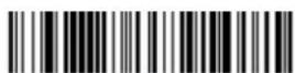
LPI_DL.
Interval Between Alerts
Low Power Alert Beep
If you do not want the beeper to sound for a low power alert, scan the Low Power Alert Beep Off bar code. Any low power alert settings will still flash the scanner LEDs, whether or not the beeper sounds. Default = Low Power Alert Beep On.

LPIBEP0.
Low Power Alert Beep Off

LPIBEP1.
*Low Power Alert Beep On
Base
The base contains colored LEDs that indicate the status of the unit, verifies its communication with the host system, and indicates scanner instant charge pack condition.
Base Communication and Scanning
The following feedback is provided by the base and indicates communication and scanning status.
| Red LED - Host Communication |
| Red LED | Communication Condition |
| Off USB suspend | |
| On continuously Host communication | available |
| Short blinks in multiple pulses. Occurs while transferring data to/from the RF module or the host port. | Receiving/sending data |
Base Charge Status
When charging, the base indicates the progress while the scanner resides in the base.
| Base Button/LED Charge Level | Approximate Expected Scans* |
| Green on 100% 450 | | |
| Green slow blink 50-99% 200 | | |
| Green fast blink 30-50% 100 | | |
| Yellow fast blink 0-30% Charging - do not scan | | |
* The number of scans was measured with a clearly printed UPC code in good light. The approximate number of scans varies with changes in label quality, symbology, and environmental factors.
Base Power Communication Indicator
To display the power indicator on a base, scan the Base Power Communication Indicator On bar code. To turn off the power indicator, scan the Off bar code.
Default = On.

*:BASRED1
* Base Power Communication Indicator On
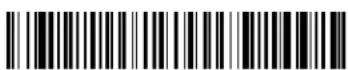
*.BASREDO
Base Power Communication Indicator Off
Reset Scanner
Scanning this bar code reboots the scanner and causes it to relink with the base.

RESET
Reset Scanner
Base Charge Modes
When the base has both an external power supply (plugged into the auxiliary power port) and a host interface cable, it will draw its power from the external power supply. When the base does not have an external power supply, it draws its power from the interface cable. However, the scanner instant charge pack charges more slowly from a host interface cable than if auxiliary power were available. Using the following selections, you can specify whether the scanner instant charge pack is charged from power supplied via the host interface cable.
When Base Charge Off is selected, the scanner instant charge pack does not charge when the scanner is in the base cradle.
When External or Interface Cable Power is selected, the scanner instant charge pack charges from the base's external power supply, if there is one. If there is no external power supply to the base, the scanner instant charge pack charges from the interface cable.
When External Power Only is selected, the scanner instant charge pack only charges from the base's external power supply. If there is no external power supply, the scanner instant charge pack does not charge.
Default = External or Interface Cable Power.

BASCHGO
Base Charge Off
BASCHG1
External or Interface Cable Power
BASCHG2
External Power Only
Page Button with Scanner Out of the Base
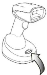
natural_image
Line drawing of a handheld scanner with a curved arrow indicating motion (no text or symbols)
When the scanner is out of the base, press the page button on the base to make the associated scanner start beeping (3 short and 1 long beep). If you pull the trigger on a scanner that is beeping in response, or press the Page button on the base a second time, the scanner stops beeping. See Paging on page 90 for further information about Page Button settings.
Page Button with Scanner in the Base
When the scanner is in the base, press the page button on the base to begin Streaming Presentation Mode. The scanner acts as a presentation scanner for 10 seconds. If a bar code is scanned before the 10 second timeout is reached, the timer starts over. Lift the scanner from the base to return to manual triggering. To change the timeout from 10 seconds see Temporary Streaming Presentation Timeout on page 89.
Temporary Streaming Presentation Timeout
Set a timeout for the length of time the illumination remains on and searching for bar codes when using Temporary Streaming Presentation Mode. Set the length for the timeout by scanning one of the bar codes below. Default = 10,000 ms (10 seconds).
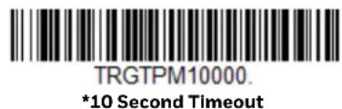



See Paging, below, for further information about Page Button settings.
Scan While in Base Cradle
If you want to be able to scan bar codes while the scanner is in the base cradle, scan the Scan in Cradle On bar code below. If you want to only allow scanning when the scanner is out of the base cradle, scan Scan in Cradle Off. If you want the scanner to shut down when in the base cradle, scan Shut Down Scanner in Cradle. Default = Scan in Cradle On.


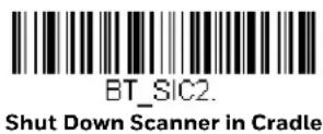
Paging
Page Mode
When the scanner is out of the base, the paging button on the base pages the scanner associated with that base. If you want to disable the paging button, scan the Page Mode Off bar code, below. When Page Mode is off, the base will no longer page the scanner when the button is pressed and no scanner is in the base. The red LED on the base remains lit to indicate that Page Mode is off. (This light will go out when the button is pressed, then back on when it's released.) Default = Page Mode On.


Page Pitch
When the scanner is out of the base and you press the Page button, the scanner associated with that base begins beeping. You can set the pitch of the paging beep for the scanner by scanning one of the following bar codes. Default = Low.

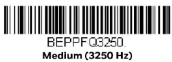
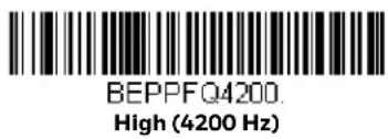
Linking Sound
Under normal operations, the scanner clicks when linking to a base. If you want to silence this sound, scan the Silent Linking bar code below. To return to the default clicking sound, scan Linking Sound. Default = Linking Sound.

Error Indicators
Beeper Pitch - Base Error
The base can be configured to beep at a particular pitch when an error occurs, such as transmission problems to a host system. The beeper pitch codes modify the pitch (frequency) of the error tone the base emits when there is an error. Default = Low.
BASFQ2250
* Razz (250 Hz)

BASFQ23250
Medium (3250 Hz)

BASFQ24200.
High (4200 Hz)
Number of Beeps - Base Error
The number of beeps and LED flashes emitted by the base for an error condition can be programmed from 1 - 9. For example, if you program this option to have five error beeps, there will be five error beeps and five LED flashes in response to an error. To change the number of error beeps, scan the bar code below and then scan a digit (1-9) from the Programming Chart, beginning on page 341, then Save. Default = 1.
BASERR
Number of Base Error Beeps/LED Flashes
Scanner Report
Scan the bar code below to generate a report for the connected scanner. The report indicates the port, scanner name, and address. To assign a name to your scanner, refer to Menu Command Syntax, page 259.
RPTSCN
Scanner Report
Scanner Address
Scan the bar code below to determine the address of the scanner you are using.

BT_LDA
Scanner Address
Base Address
Scan the bar code below to determine the address of the base you are using.

Scanner Modes
Charge Only Mode
There may be times when you want to charge your scanner, but not link to the base. In order to program the base for Charge Only Mode, you must link the scanner to it. Once the scanner is linked to the base, scan the Charge Only Mode bar code. Any subsequent scanners placed in that base will charge without linking to it. The scanner used to program the base remains linked to the base. To unlink this scanner, scan Unlink Scanner on page 94.

Note: When in Charge Only Mode, the scanner periodically wakes up and beeps. See Power Up Beeper on page 111 to change this setting.
Charge and Link Mode
If you want to charge a scanner and link to the base, use Charge and Link Mode. If the base is programmed for Charge Only Mode, you must link a scanner to it first in order to program it for Charge and Link Mode. Scan the linking bar code on the base to link the scanner, then scan Charge and Link Mode. Default = Charge and Link Mode.

Linked Modes
Locked Link Mode and Open Link Mode are the link modes that accommodate different applications. Scan the appropriate bar codes included in the Open Link and Locked Link Mode explanations that follow to switch from one mode to another. Default = Open Link Mode.
Locked Link Mode - Single Scanner
If you link a scanner to a base using the Locked Link Mode, other scanners are blocked from being linked if they are inadvertently placed into the base. If you do place a different scanner into a base, it will charge the scanner, but the scanner will not be linked.

BASCON0,DNG1
Locked Link Mode
(Single Scanner)
To use a different scanner, you need to unlink the original scanner by scanning the Unlink Scanner bar code. (See Scanner Modes, page 93.)
Open Link Mode - Single Scanner
When newly shipped or defaulted to factory settings, a scanner is not linked to a base. A link is established when the scanner is placed into a base. When in Open Link Mode, a new link is established when a new scanner is placed in the base. Each time a scanner is placed into a base, the scanner becomes linked to the base and the old scanner is unlinked.

BASCON1,DNG1
* Open Link Mode
(Single Scanner)
Unlink the Scanner
If a base has a scanner linked to it, that scanner must be unlinked before a new scanner can be linked. Once the previous scanner is unlinked, it will no longer communicate with the base. To unlink the scanner from a base, scan the Unlink Scanner bar code below.

BT RMV
Unlink Scanner
Override Locked Scanner
If you need to replace a broken or lost scanner that is linked to a base, scan the Override Locked Scanner bar code below with a new scanner and place that scanner in the base. The locked link is overridden, the broken or lost scanner's link with the base is removed, and the new scanner is linked to the base.
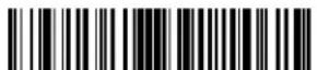
BT_RPL1.
Override Locked Scanner
(Single Scanner)
Out-of-Range Alarm
If your scanner is out range of the base, an alarm sounds from both your base and scanner. The alarm stops when the scanner is moved closer to the base, when the base connects to another scanner, or when the alarm duration expires. To activate the alarm options for the scanner or the base and to set the alarm duration, scan the appropriate bar code below and then set the time-out duration (from 0-3000 seconds) by scanning digits on the Programming Chart, beginning on page 341, then Save.

BASORD
Base Alarm Duration

BT ORD
Scanner Alarm Duration
Note: If you are out of range when you scan a bar code, you will receive an error tone even if you do not have the alarm set. You receive the error tone since the data could not be communicated to the base or the host.
Alarm Sound Type
You may change the alarm type for the scanner or a base by scanning the appropriate bar code below and then scanning a digit (0-7) bar code from the Programming Chart, beginning on page 341, then Save. Default = 0.
The sounds are as follows:
| Setting Sound |
| 0 3 long beeps, medium pitch |
| 1 3 long beeps, high pitch |
| 2 4 short beeps, medium pitch |
| 3 4 short beeps, high pitch |
| 4 single chirps, medium pitch |
| 5 2 chirps, then 1 chirp, medium pitch |
| 6 single chirps, high pitch |
| 7 2 chirps, then 1 chirp, high pitch |

BASORW
Base Alarm Type
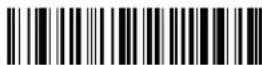
BT_ORW
Scanner Alarm Type
Scanner Power Time-Out Timer
When there is no activity within a specified time period, the scanner enters low power mode. Scan the appropriate scanner power time-out bar code to change the time-out duration (in seconds).
Note: Scanning zero (0) is the equivalent of setting no time-out.
If there are no trigger pulls during the timer interval, the scanner goes into power down mode. Whenever the trigger is enabled, the timer is reset. If the scanner is placed in the base and the instant charge pack is in the process of being charged, the scanner will not go into power down mode. Default = 400 seconds.


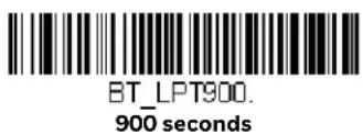


Note: When the scanner is in power down mode, pull the trigger to power the unit back up. There will be a set of power up beeps and a delay of up to a few seconds for the radio to join. The scanner will then be ready to use.
Flexible Power Management
If you are experiencing network performance issues, and suspect the scanner is interfering with other devices, you can turn down the power output of the scanner. This reduces the range between the scanner and a base as shown in the following illustration:

Scan one of the bar codes below to set the scanner's power output to Full Power (100%), Medium High Power (88%), Medium Power (50%), or Low Power (1%). Default = High Power.

BT TXP8
Full Power

BT_TXP7
* Medium High Power

BT TXP4
Medium Power

BT TXP1
Low Power
Batch Mode
Batch mode is used to store bar code data when a scanner is out of range of its base, or when performing inventory. The data is transmitted to the base once the scanner is back in range or when the records are manually transmitted.
Automatic Batch Mode stores bar code data when the scanner is out of range of the base. The data is automatically transmitted to the base once the scanner is back in range. When the scanner's buffer space is full, any bar codes scanned generate an error tone. In order to scan bar codes again, the scanner must be moved back into range of the base so data can be transmitted.
Inventory Batch Mode stores bar code data, whether or not you are in range of the base. To transmit the stored data to the base, either place the scanner in the base, or scan Transmit Inventory Records (page 103). When the scanner's buffer space is full, any bar codes scanned generate an error tone. In order to scan bar codes again, the data must be transmitted to the base. Once the data is transmitted, it is cleared in the scanner.
Persistent Batch Mode is the same as Inventory Batch Mode, except that once the data is transmitted to the base, it is retained in the scanner. If you want to transmit more than once, you can do so using this mode. In order to clear the scanner's buffer, you must scan Clear All Codes (see page 103).
Default = Batch Mode Off.

BATENAD
* Batch Mode Off
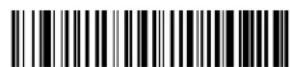
BATENA2
Inventory Batch Mode

BATENA1
Automatic Batch Mode

BATENA3
Persistent Batch Mode
Batch Mode Beep
When scanning in Inventory Batch Mode (page 99), the scanner beeps every time a bar code is scanned. When Batch Mode Beep is On, you will also hear a click when each bar code is sent to the host. If you do not want to hear these clicks, scan Batch Mode Beep Off. Default = Batch Mode Beep On.

BATBEPO.
Batch Mode Beep Off

BATBEP1
* Batch Mode Beep On
Batch Mode Storage
When a scanner is storing data during a Batch Mode process, you can select whether the data is stored in Flash memory or in RAM.
Flash Storage: The scanner writes any untransmitted data to flash memory prior to powering down. The data will still be there when the scanner powers back up. However, the scanner will power down, even with untransmitted data, if it reaches a power down timeout or if the instant charge pack power is very low.
RAM Storage: The scanner will not power down while it contains data that has not been transmitted to the base, even if it reaches a power down timeout. However, if the scanner charge pack runs out of power, it will power down and the data will be lost.
Default = Flash Storage.
BATNVS1.
* Flash Storage
Batch Mode Quantity
When in Batch Mode, you may wish to transmit the number of multiple bar codes scanned, rather than a single bar code multiple times. For example, if you scan three bar codes called XYZ with Batch Mode Quantity Off, when you transmit your data it will appear as XYZ three times. Using Batch Mode Quantity On and the Quantity Codes (page 101), you could output your data as "XYZ, 00003" instead.
Note: If you wish to format your output, for example, place a CR or tab between the bar code data and the quantity, refer to Data Format beginning on page 157.
Default = Batch Mode Quantity Off.
* Batch Mode Quantity Off
BATQTY1
Batch Mode Quantity On
Enter Quantities
Quantity Codes (page 101) allow you to enter a quantity for the last item scanned, up to 9999 (default = 1). Quantity digits are shifted from right to left, so if a 5th digit is scanned, the 1st digit scanned is discarded and the 2nd, 3rd and 4th digits are moved to the left to accommodate the new digit.
For example, if the Quantity 5 bar code is scanned after the quantity has been set to 1234, then the 1 is dropped, the quantity will be 2345.
Example: Add a quantity of 5 for the last item scanned.
- Scan the item's bar code.
- Scan the quantity 5 bar code.
Example: Add a quantity of 1,500 for the last item scanned.
- Scan the item's bar code.
- Scan the quantity 1 bar code.
- Scan the quantity 5 bar code.
-
Scan the quantity 0 bar code.
-
Scan the quantity 0 bar code.
Example: Change a quantity of 103 to 10.
To correct an incorrect quantity, scan the quantity 0 bar code to replace the incorrect digits, then scan the correct quantity bar codes.
- Scan the quantity 0 bar code to change the quantity to 1030.
- Scan the quantity 0 bar code to change the quantity to 0300.
- Scan the quantity 1 bar code to change the quantity to 3001.
- Scan the quantity 0 bar code to change the quantity to 0010.
Default = 1.
Quantity Codes


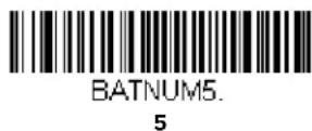

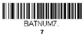
Quantity Codes (Continued)
BATNUM8.
8

BATNUM9.
9
Batch Mode Output Order
When batch data is transmitted, select whether you want that data sent as FIFO (first-in first-out), or LIFO (last-in first-out). Default = Batch Mode FIFO.

BATLIFO
* Batch Mode FIFO

BATLIF1
Batch Mode LIFO
Total Records
If you wish to output the total number of bar codes scanned when in Batch Mode, scan Total Records.
BATNRC.
Total Records
Delete Last Code
If you want to delete the last bar code scanned when in Batch Mode, scan Delete Last Code.

BATUND.
Delete Last Code
Clear All Codes
If you want to clear the scanner's buffer of all data accumulated in Batch Mode, scan Clear All Codes.

BATCLR
Clear All Codes
Transmit Records to Host
If you are operating in Inventory Batch Mode (see Inventory Batch Mode on page 99), you must scan the following bar code to transmit all the stored data to the host system.

BAT_TX
Transmit Inventory Records
Batch Mode Transmit Delay
Sometimes when accumulated scans are sent to the host system, the transmission of those scans is too fast for the application to process. To program a transmit delay between accumulated scans, scan one of the following delays. Default = Off.
Note: In most cases, a short (250 ms (milliseconds)) delay is ideal, however, longer delays may be programmed. Contact Technical Support (page xvii) for additional information.
BATDLYO
* Batch Mode Transmit Delay Off (No Delay)
BATDLY250
Batch Mode Transmit Delay Short (250 ms)
BATDLY500
Batch Mode Transmit Delay Medium (500 ms)

BATDLY1000
Batch Mode Transmit Delay Long (1000 ms)
Scanner Name
You may assign a name to each scanner you are using for identification purposes. The default name is in the format "ScannerName_Model_SN_XXXXXXXXXX" Perform the rename operation using either the bar codes on page 105, or by sending the serial command :ScannerName:BT_NAMNewName. where ScannerName is the current name of the scanner, and NewName is the new name for the scanner.
To rename scanners with sequential, numeric names, scan the bar codes below. Scan the Reset code after each name change and wait for the scanner to relink to the base before scanning a bar code to rename the next scanner.


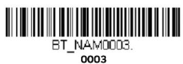



You may also scan the Scanner Name bar code below and scan a number for the scanner name. For example, if you wanted to name the linked scanner "312," you would scan the bar code below, scan the 3, 1, and 2 bar codes on the Programming Chart, beginning on page 341, then Save. Scan the Reset bar code and wait for the scanner to relink to the base.

BT NAM
Scanner Name
Change the Scanner's Bluetooth PIN Code
Some devices require a PIN code as part of the Bluetooth security features. Your scanner's default PIN is 1234, which you may need to enter the first time you connect to your PC. The PIN code must be between 1 and 16 characters. To change the PIN, scan the bar code below and then scan the appropriate numeric bar codes from the Programming Chart, beginning on page 341, then Save.

BT_PIN
Bluetooth PIN
Minimize Bluetooth/ISM Band Network Activity
The settings described below can help you customize the relinking behavior of the cordless area-imaging system to obtain the best compromise between convenience and low interference.
Note: ISM band refers to the 2.4 to 2.48 GHz frequency band used by wireless networks, cordless phones, and Bluetooth.
Auto Reconnect Mode
Auto Reconnect controls whether or not the scanner automatically begins the relink process when a loss of connection is detected. When the Auto Reconnect On bar code is scanned, the scanner begins the relink process immediately, without user intervention. Default = Auto Reconnect On.

BT_ACM1
* Auto Reconnect On

BT ACMO
Auto Reconnect Off
The table below shows the results of the Auto Reconnect On and Off settings:
| Event Auto Reconnect On | Auto Reconnect Off | |
| Scanner out of range Relink occurs automatically. If maximum number of link attempts is unsuccessful, then the scanner must be relinked by either pulling the trigger or placing the scanner in the base. (See Maximum Link Attempts on page 106.) | The scanner is relinked by pulling the trigger. |
| Base reset (firmware upgrade or power cycle) | Scanner behaves as if out of range. No attempt to relink made while base is powered off. Trigger must be pulled to initiate relinking. |
| Scanner power down due to Power Time-Out Timer setting | Trigger must be pulled or the scanner must be placed in the base unit to relink.(Note: scanner relinks on power up, but powers on due to one of the above actions.) |
| Scanner reset due to firmware upgrade | Relink occurs automatically. |
| Scanner reset due to instant charge pack change | Relink occurs automatically. |
| Scanner placed in different base unit | Relink to new base occurs automatically. |
Maximum Link Attempts
The Maximum Link Attempts setting controls the number of times the scanner tries to form a connection with a base. During the connection setup process, the scanner transmits in order to search for and connect to a base. In order to prevent continuous transmissions that could interfere with other users of the ISM band, the number of attempts to connect is limited by this setting. After the maximum number of attempts is reached, the scanner will not attempt to reconnect to a base. Pressing the trigger or placing the scanner in the base resets the counter and the scanner will again try to link.
Scan the Maximum Link Attempts bar code, then scan the number of attempts for the setting (from 0-100) from the Programming Chart, beginning on page 341, then Save. Default = 4.
BT MLA.
Maximum Link Attempts
Note: When Auto Reconnect Mode is On, setting Maximum Link Attempts to zero will cause the scanner to try to link until the Power Time-Out Timer setting expires. When Auto Reconnect Mode is Off, setting Maximum Link Attempts to zero will cause the scanner to only attempt linking one time after a trigger pull.
Relink Time-Out
Relink Time-Out controls the idle time between relink attempts. An attempt to link a scanner to a base typically lasts up to 5 seconds. This is the time when the scanner is actually attempting a contact. Relink Time-Out controls the amount of time, in seconds, that elapses between the end of one connection attempt and the start of the next.
Scan the Relink Time-Out bar code, then scan the number of seconds for the setting (from 1-100) from the Programming Chart, beginning on page 341, then Save. Default = 2 seconds.

BT_RLT
Relink Time-Out
Bluetooth/ISM Network Activity Examples
Default values
When the scanner goes out of range, the scanner repeatedly attempts to connect to the base. Each attempt consists of approximately 5 seconds of active time followed by 3 seconds of idle time. After one hour, the scanner powers off and batch mode data is lost.
Example: Maximum Link Attempts set to 15
Other values at default setting
When the scanner goes out of range, 15 attempts are made to link to the base. Each attempt consists of approximately 5 seconds of active time followed by 3 seconds of idle time. After 15 cycles (8*15 =120), or about 2 minutes, the scanner stops trying to connect to the base, but retains any bar codes that may have been saved in batch mode. After one hour, the scanner powers off and batch mode data is lost.
Example: Auto Reconnect Mode set to 0
Maximum Link Attempts set to 15
Other values at default setting
When the scanner goes out of range, no action is taken to relink. When the trigger is pulled, 15 attempts are made to link to the base. Each attempt consists of approximately 5 seconds of active time followed by 3 seconds of idle time. After 15 cycles (8*15 =120), or about 2 minutes, the scanner stops trying to connect to the
base, but retains any bar codes that may have been saved in batch mode. After one hour, the scanner powers off and batch mode data is lost. Refer to Auto Reconnect Mode, page 105, to review other events that can start the relink process.
Example: Auto Reconnect Mode set to 1
Maximum Link Attempts set to 0
Relink Time-Out set to 10
Scanner Power Time-Out Timer set to 1800
Note: See Scanner Power Time-Out Timer on page 96.
The scanner attempts to connect to the base every 15 seconds, measured from one attempt start to the next attempt start. After one half hour, the scanner powers off.
Host Acknowledgment
Some applications require that the host terminal (or server) validate incoming bar code data (database look-up) and provide acknowledgment to the scanner whether or not to proceed. In Host ACK Mode, the scanner waits for this acknowledgment after each scan. Visual and audible acknowledgments provide valuable feedback to the scan operator. The Host ACK functionality is controlled via a number of pre-defined escape commands that are sent to the scanner to make it behave in different ways.
Note: System performance degrades when using Host ACK at rates lower than 9600 baud.
The following criteria must be met for the Host ACK to work correctly:
- The cordless system must be configured for Host Port RS232 (terminal ID = 000) or USB COM Emulation (terminal ID = 130).
- RTS/CTS is defaulted off. You must enable it if the host system requires it.
- Host ACK must be set to On (page 109).
- A comma must be used as a terminator.
- The host terminal software must be capable of interpreting the bar code data, make decisions based on the data content, and send out appropriate escape commands to the scanner.
The commands to which the scanner responds are listed on page 110. The [ESC] is a 1B in hex. A typical command string is [ESC] x, [ESC] x is the escape command, and the comma is the terminator, which is required.
Example: Commands may be strung together to create custom response sequences. An example of a command string is listed below.
[ESC]4,[ESC]5,[ESC]6,
The above example will make a scanner beep low, then medium, then high.
Example: A good read beep is required for any item on file, but a razz or error tone is required if the item is not on file. In this case,
[ESC]7, is sent from the host to the scanner for an on-file product
[ESC]8,[ESC]8, is sent from the host to the scanner for a not-on-file product
When a bar code is scanned, the scanner enters a timeout period until either the host ACK sequence is received, or the timeout expires (in 10 seconds, by default).
Once Host ACK is enabled, the system works as follows when a bar code is scanned:
- The scanner reads the code and sends data to the base to transmit to the host system. No audible or visual indication is emitted until the scanner receives an escape command. The scanner read illumination goes out when there's a successful read.
- Scanner operation is suspended until 1) a valid escape string is received from the host system or 2) the scanner times out.
- Once condition 1 or 2 above has been met, the scanner is ready to scan again, and the process repeats.
A time-out occurs if the scanner does not receive a valid escape command within 10 seconds. A time-out is indicated by an error tone. If a time-out occurs, the operator should check the host system to understand why a response to the scanner was not received.
Host ACK On/Off

HSTACK1
Host ACK On

HSTACKO
* Host ACK Off
Host ACK Timeout
You can set a timeout for the length of time the scanner waits for a valid escape command when using Host Acknowledgment Mode. Set the length (in seconds) for a timeout by scanning the following bar code, then setting the timeout (from 1-90 seconds) by scanning digits from the Programming Chart, beginning on page 341, then Save. Default = 10.

HSTATO.
Host ACK Timeout
Host ACK Responses
| Command Action | |
| [ESC] a, Double beeps to indicate a successful menu change was made. |
| [ESC] b, Razz or error tone to indicate a menu change was unsuccessful. |
| [ESC] 1, The green LED illuminates for 135 milliseconds followed by a pause. |
| [ESC] 2, The green LED illuminates for 2 seconds followed by a pause. |
| [ESC] 3, The green LED illuminates for 5 seconds followed by a pause. |
| [ESC] 4, Emits a beep at a low pitch. |
| [ESC] 5, Emits a beep at a medium pitch. |
| [ESC] 6, Emits a beep at a high pitch. |
| [ESC] 7, Beeps to indicate a successful decode and communication to host. |
| [ESC] 8,[ESC] 8, | Razz or error tone to indicate a decode/communication to host was unsuccessful. |
Power Up Beeper
Note: This feature does not apply to the CCB02-100BT/CCB05-100BT base.
The scanner can be programmed to beep when it's powered up. If you are using a cordless system, the base can also be programmed to beep when it is powered up. Scan the Off bar code(s) if you don't want a power up beep. Default = Power Up Beeper On - Scanner.
BEPPWRO.
Power Up Beeper Off - Scanner

BEPPWR1
* Power Up Beeper On - Scanner

BASPWRO
Power Up Beeper Off - Cordless Base

BASPWR1
Power Up Beeper On - Cordless Base
Beep on BEL Character
You may wish to force the scanner to beep upon a command sent from the host. If you scan the Beep on BEL On bar code below, the scanner will beep every time a BEL character is received from the host. Default = Beep on BEL Off.

BELBEPO
*Beep on BEL Off

BELBEP1
Beep on BEL On
Trigger Click
To hear an audible click every time the scanner trigger is pressed, scan the Trigger Click On bar code below. Scan the Trigger Click Off code if you don't wish to hear the click. (This feature has no effect on serial or automatic triggering.) Default = Trigger Click Off.

BEPTRGO
*Trigger Click Off
BEPTRG1
Trigger Click On
Good Read and Error Indicators
Beeper – Good Read
The beeper may be programmed On or Off in response to a good read. Turning this option off only turns off the beeper response to a good read indication. All error and menu beeps are still audible. Default = Beeper - Good Read On.
BEPBEPO
Beeper - Good Read Off

BEPBEP1.
* Beeper - Good Read On
Beeper Volume – Good Read
The beeper volume codes modify the volume of the beep the scanner emits on a good read. Default = High for Granit/Xenon, Low for Xenon HC.


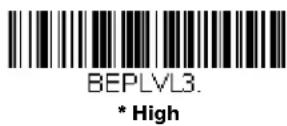

Beeper Pitch – Good Read
The beeper pitch codes modify the pitch (frequency) of the beep the scanner emits on a good read. The Medium pitch differs for the Xenon and Granit scanners. Default = Medium.
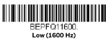


Vibrate – Good Read
Note: Vibration settings apply only to Granit Devices.
The scanner vibrates once when a bar code is successfully read, and twice when a programming bar code is successfully read. When a programming bar code is unsuccessful, the scanner emits one long vibration (2 times the Vibrate Duration length). Scan Vibrate - Good Read Off to keep the scanner from vibrating. Default = Vibrate - Good Read On.
TFBGRDO
Vibrate- Good Read Off

TFBGRD1
* Vibrate- Good Read On
Vibrate Duration
If you want to set the length for the good read vibration, scan the bar code below, then set the duration (from 100 - 2,000 milliseconds) by scanning digits from the Programming Chart, beginning on page 341, then Save. Default = 300 ms.

TFBDUR.
Vibrate Duration
Beeper Pitch – Error
The beeper pitch codes modify the pitch (frequency) of the sound the scanner emits when there is a bad read or error. Default = Razz.

BEPFQ2250
* Razz (250 Hz)

BEPFQ23250
Medium (3250 Hz)

BEPFQ24200.
High (4200 Hz)
Beeper Duration – Good Read
The beeper duration codes modify the length of the beep the scanner emits on a good read. Default = Normal.

BEPBIPO
* Normal Beep

BEPBIP1
Short BeepShort Beep
LED - Good Read
The LED indicator can be programmed On or Off in response to a good read. Default = On.

BEPLED1
* LED - Good Read On

BEPLEDO
LED - Good Read Off
Number of Beeps – Good Read
The number of beeps of a good read can be programmed from 1 - 9. The same number of beeps will be applied to the beeper and LED in response to a good read. For example, if you program this option to have five beeps, there will be five beeps and five LED flashes in response to a good read. The beeps and LED flashes are in sync with one another. To change the number of beeps, scan the bar code below and then scan a digit (1-9) bar code from the Programming Chart, beginning on page 341, then Save. Default = 1.

BEPRPT
Number of Good Read Beeps/LED Flashes
Number of Beeps – Error
The number of beeps and LED flashes emitted by the scanner for a bad read or error can be programmed from 1 - 9. For example, if you program this option to have five error beeps, there will be five error beeps and five LED flashes in response
to an error. To change the number of error beeps, scan the bar code below and then scan a digit (1–9) bar code from the Programming Chart, beginning on page 341, then Save. Default = 1.
BEPERR
Number of Error Beeps/LED Flashes
Beeper Volume Max
Note: The Beeper Volume Max feature only applies to Granit products.
Scan the following bar code to set all error and good read beeps to the maximum volume. This feature also sets the Beeper Pitch – Good Read to the highest level.
PAPBLM
Beeper Volume Max
Good Read Delay
This sets the minimum amount of time before the scanner can read another bar code. Default = 0 ms (No Delay).

DLYGRDO
* No Delay

DLYGRD500.
Short Delay (500 ms)

DLYGRD1000
Medium Delay (1,000 ms)

DLYGRD1500
Long Delay (1,500 ms)
User-Specified Good Read Delay
If you want to set your own length for the good read delay, scan the bar code below, then set the delay (from 0 - 30,000 milliseconds) by scanning digits from the Programming Chart, beginning on page 341, then Save.
DLYGRD
User-Specified Good Read Delay
Trigger Modes
Manual Trigger
When in manual trigger mode, the scanner scans until a bar code is read, or until the trigger is released. Two modes are available, Normal and Enhanced. Normal mode offers good scan speed and the longest working ranges (depth of field). Enhanced mode will give you the highest possible scan speed but slightly less range than Normal mode. Enhanced mode is best used when you require a very fast scan speed and don't require a long working range. Default = Manual Trigger-Normal.
Note: Granit 1980i and 1981i do not support Enhanced Manual Trigger Mode.
PAPHHF.
* Manual Trigger - Normal

PAPHHS
Manual Trigger - Enhanced
Trigger Toggle
Note: Only the Xenon 1900 and 1902 support Trigger Toggle mode.
Trigger Toggle mode lets you quickly hit the trigger 2 or 3 times to put the scanner into either imaging mode, cell phone read mode, or centering mode, then toggle back to scanning. So, like a double-click with a mouse, you can control what the next scanner's action will be. For example, you could double-press the trigger to go into imaging mode, then the next trigger press takes the image. The scanner then reverts to scanning mode. Or you could triple-press the trigger to go into cell phone read mode, the customer presents the phone and it's read, then the scanner reverts to scanning mode. Use the following codes to configure what action you would like the scanner to take when in Trigger Toggle mode.
TRGTGM0.
*Trigger Toggle Off

TRGTGM1
Trigger Toggle - Image Capture

TRGTGM2.
Trigger Toggle - Cell Phone Read

TRGTGM3
Trigger Toggle - Centering
Trigger Number
This sets the number of trigger preses required to activate the Trigger Toggle Mode.

TRGTPC2.
2 Quick Triggers

TRGTPC3
3 Quick Triggers
TRGTPC4.
4 Quick Triggers
Trigger Timing
This sets the timing of the trigger presses in order to qualify as a trigger toggle, rather than a regular trigger press. After scanning the Trigger Timing bar code, set the time-out duration (from 50-2,000 milliseconds) by scanning digits from the Programming Chart, beginning on page 341, then Save. Default = 400ms.

TRGTTI.
Trigger Timing
Trigger Toggle Timeout
This sets the length of time the scanner stays in trigger toggle mode before reverting to scan mode. After scanning the Trigger Toggle Timeout bar code, set the time-out duration (from 0 to 65 seconds) by scanning digits from the Programming Chart, beginning on page 341, then Save. Default = 5 seconds.
Note: If this is set to 0, you must repeat the toggle sequence to return to the default scanning mode. For example, if 2 quick trigger presses puts the scanner into cell phone read mode and the Trigger Timing is 0, you would have to do 2 quick presses again to go back to the default scanning mode.

TRGTGT
Trigger Toggle Timeout
Serial Trigger
You can activate the scanner either by pressing the trigger, or using a serial trigger command (see Trigger Commands on page 262). You must be in a serial interface mode in order to use serial triggering. Refer to RS232 Serial Port (page 16) or USB Serial (page 19) for further information. When in serial mode, the scanner scans until a bar code has been read or until the deactivate command is sent. The scanner can also be set to turn itself off after a specified time has elapsed (see Read Time-Out, which follows).
Read Time-Out
Use this selection to set a time-out (in milliseconds) of the scanner's trigger when using serial commands to trigger the scanner. Once the scanner has timed out, you can activate the scanner either by pressing the trigger or using a serial trigger command. After scanning the Read Time-Out bar code, set the time-out duration (from 0-300,000 milliseconds) by scanning digits from the Programming Chart, beginning on page 341, then Save. Default = 30,000 ms.

TRGSTO
Read Time-Out
Presentation Mode
Presentation Mode uses ambient light and scanner illumination to detect bar codes. When in Presentation Mode, the LEDs remain dim until a bar code is presented to the scanner, then the aimer turns on and the LEDs turn up to read the code. If the light level in the room is not high enough, Presentation Mode may not work properly
Note: If you are using a cordless charge base in Presentation Mode, the battery will not charge unless the power supply is plugged into the base's auxiliary power port.
Scan the following bar code to program your scanner for Presentation Mode.
PAPTPR
Presentation Mode
Presentation LED Behavior after Decode
When a scanner is in presentation mode, the LED aimer dims 30 seconds after a bar code is decoded. If you wish to dim the LED aimer immediately after a bar code is decoded, scan the LEDs Off bar code, below. Default = LEDs On.

TRGPCK1
* LEDs On
TRGPCKD
LEDs Off
Presentation Sensitivity
Presentation Sensitivity is a numeric range that increases or decreases the scanner's reaction time to bar code presentation. To set the sensitivity, scan the Sensitivity bar code, then scan the degree of sensitivity (from 0-20) from the Programming Chart, beginning on page 341, then Save. 0 is the most sensitive setting, and 20 is the least sensitive. Default = 1.
Note: Granit 1980i and 1981i do not support this setting.

TRGPMS.
Sensitivity
Presentation Centering
Use Presentation Centering to narrow the scanner's field of view when it is in the stand to make sure the scanner reads only those bar codes intended by the user. For instance, if multiple codes are placed closely together, Presentation Centering will insure that only the desired codes are read.
Note: To adjust centering when the scanner is hand-held, see Centering (page 5-131).
If a bar code is not touched by a predefined window, it will not be decoded or output by the scanner. If Presentation Centering is turned on by scanning Presentation Centering On, the scanner only reads codes that pass through the centering window you specify using the Top of Presentation Centering Window, Bottom of Presentation Centering Window, Left, and Right of Presentation Centering Window bar codes.
In the example below, the white box is the centering window. The centering window has been set to 20% left, 30% right, 8% top, and 25% bottom. Since Bar Code 1 passes through the centering window, it will be read. Bar Code 2 does not pass through the centering window, so it will not be read.
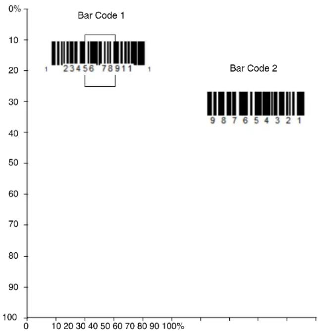
bar
| Category | Value |
|---|---|
| Bar Code 1 | 1 |
| Bar Code 1 | 23456 |
| Bar Code 1 | 78911 |
| Bar Code 1 | 1 |
| Bar Code 2 | 9 |
| Bar Code 2 | 8 |
| Bar Code 2 | 7 |
| Bar Code 2 | 6 |
| Bar Code 2 | 5 |
| Bar Code 2 | 4 |
| Bar Code 2 | 3 |
| Bar Code 2 | 2 |
| Bar Code 2 | 1 |
Note: A bar code needs only to be touched by the centering window in order to be read. ?It does not need to pass completely through the centering window.
Scan Presentation Centering On, then scan one of the following bar codes to change the top, bottom, left, or right of the centering window. Then scan the percent you want to shift the centering window from the Programming Chart, beginning on page 341, then Save. Default Presentation Centering = 40% for Top and Left, 60% for Bottom and Right.


In-Stand Sensor Mode
Note: The In-Stand Sensor feature only applies to Xenon 1900, 1900h, 1910, 1902, 1902h, and 1912products. It does not apply to the Xenon 1902g-BF or Granit products.
This feature senses when the scanner is removed from the stand and tells it to begin manual triggering. When Sensor On is enabled, the scanner defaults to Streaming Presentation Mode when it is in the stand, and to Manual Trigger Mode when it is removed from the stand. Default = Sensor On.
TRGSSW1
* Sensor On

TRGSSWO.
Sensor Off
Note: If you are taking images (see Imaging Commands beginning on page 233), you must set the In-Stand Sensor to Off.
You may program a Streaming Presentation Mode (Normal, Enhanced, or Mobile Phone) you wish to use for in-stand scanning, and a Manual Trigger mode (Normal, Enhanced, or Mobile Phone) you wish to use for out-of-stand scanning. To do this, you must first scan the preferred Streaming Presentation mode (see below), then scan the Manual Trigger mode (see page 117 and page 125) you want to use.
Poor Quality Codes
Poor Quality 1D Codes
This setting improves the scanner's ability to read damaged or badly printed linear bar codes. When Poor Quality 1D Reading On is scanned, poor quality linear bar code reading is improved, but the scanner's snappiness is decreased, making it less aggressive when reading good quality bar codes. This setting does not affect 2D bar code reading. Default = Poor Quality 1D Reading Off.

DECLDI1.
Poor Quality 1D Reading On
DECLDIO.
* Poor Quality 1D Reading Off
Poor Quality PDF Codes
This setting improves the scanner's ability to read damaged or badly printed PDF codes by combining information from multiple images. When Poor Quality PDF On is scanned, poor quality PDF code reading is improved, but the scanner's snap-
piness is decreased, making it less aggressive when reading good quality bar codes. This setting does not affect 1D bar code reading. Default = Poor Quality PDF Reading Off.

Poor Quality PDF Reading On

* Poor Quality PDF Reading Off
CodeGate®
When CodeGate is On, the trigger is used to allow decoded data to be transmitted to the host system. The scanner remains on, scanning and decoding bar codes, but the bar code data is not transmitted until the trigger is pressed. When CodeGate is Off, bar code data is transmitted when it is decoded. Default = CodeGate Off Out-of-Stand.
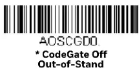
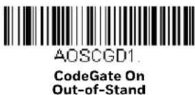
Streaming Presentation™ Mode
When in Streaming Presentation mode, the scanner's aimer goes out after a short time, but the scan illumination remains on all the time to continuously search for bar codes. Two modes are available, Normal and Enhanced. Normal mode offers good scan speed and the longest working ranges (depth of field). Enhanced mode will give you the highest possible scan speed but slightly less range than Normal mode. Enhanced mode is best used when you require a very fast scan speed and don't require a long working range.
Note: Granit 1980i and 1981i do not support Enhanced Streaming Presentation Mode.

PAPSPN
Streaming Presentation
Mode - Normal

PAPSPE
Streaming Presentation
Mode - Enhanced
When using Preferred Symbology (page 5-134), a lower priority symbol must be centered on the aiming pattern to be read in Streaming Presentation Mode.
Note: If you are using a cordless charge base, it must have an external power supply plugged into the aux port for Streaming Presentation to work properly.
Streaming Presentation In-Stand
This option is available when using In-Stand Sensor Mode, page 122. You may program a specific Streaming Presentation Mode for in-stand scanning, and a Manual Trigger mode for out-of-stand scanning. To do this, you must first scan the preferred Streaming Presentation mode (Normal, Enhanced, or Mobile Phone), then scan the Manual Trigger mode (Normal, Enhanced, or Mobile Phone) you want to use.
Mobile Phone Read Mode
When this mode is selected, your scanner is optimized to read bar codes from mobile phone or other LED displays. However, the speed of scanning printed bar codes may be slightly lower when this mode is enabled. You can enable Mobile Phone Reading for either a hand held device, or for a hands-free (presentation) application.
Note: Granit 1980i and 1981i do not support these settings.

PAPHHC
Hand Held Scanning - Mobile
Phone

PAPSPC.
Streaming Presentation -
Mobile Phone
Note: To turn off Mobil Phone Read Mode, scan a Manual or Serial Trigger Mode bar code (see page 117).
Hands Free Time-Out
The Scan Stand and Presentation Modes are referred to as “hands free” modes. If the scanner’s trigger is pulled when using a hands free mode, the scanner changes to manual trigger mode. You can set the time the scanner should remain in manual trigger mode by setting the Hands Free Time-Out. Once the time-out value is reached, (if there have been no further trigger pulls) the scanner reverts to the original hands free mode.
Scan the Hands Free Time-Out bar code, then scan the time-out duration (from 0-300,000 milliseconds) from the Programming Chart, beginning on page 341, then Save. Default = 5,000 ms.

TRGPTO
Hands Free Time-Out
Reread Delay
This sets the time period before the scanner can read the same bar code a second time. Setting a reread delay protects against accidental rereads of the same bar code. Longer delays are effective in minimizing accidental rereads. Use shorter delays in applications where repetitive bar code scanning is required. Reread Delay only works when in a Presentation Mode (see page 120). Default = Medium.

DLYRRD500
Short (500 ms)

DLYRRD750
* Medium (750 ms)

DLYRRD1000.
Long (1000 ms)

DLYRRD2000.
Extra Long (2000 ms)
User-Specified Reread Delay
If you want to set your own length for the reread delay, scan the bar code below, then set the delay (from 0-30,000 milliseconds) by scanning digits from the Programming Chart, beginning on page 341, then Save.
DLYRRD
User-Specified Reread Delay
2D Reread Delay
Sometimes 2D bar codes can take longer to read than other bar codes. If you wish to set a separate Reread Delay for 2D bar codes, scan one of the programming codes that follows. 2D Reread Delay Off indicates that the time set for Reread Delay is used for both 1D and 2D bar codes. Default = 2D Reread Delay Off.

DLY2RR0.
* 2D Reread Delay Off

DLY2RR1000
Short (1000ms)

DLY2RR2000
Medium (2000ms)

DLY2RR3000
Long (3000ms)
DLY2RR4000
Extra Long (4000ms)
Character Activation
You may use a character sent from the host to trigger the scanner to begin scanning. When the activation character is received, the scanner continues scanning until either the Character Activation Timeout (page 5-129), the deactivation character is received (see Deactivation Character on page 129), or a bar code is trans-
mitted. Scan the following On bar code to use character activation, then use Activation Character (page 128) to select the character you will send from the host to start scanning. Default = Off.

Activation Character
This sets the character used to trigger scanning when using Character Activation Mode. On the ASCII Conversion Chart (Code Page 1252), page 330, find the hex value that represents the character you want to use to trigger scanning. Scan the following bar code, then use the Programming Chart to read the alphanumeric combination that represents that ASCII character. Scan Save to finish. Default = 12 [DC2].

End Character Activation After Good Read
After a bar code is successfully detected and read from the scanner, the illumination can be programmed either to remain on and scanning, or to turn off. When End Character Activation After Good Read is enabled, the illumination turns off and stops scanning after a good read. If you scan Do Not End Character Activation After Good Read, the illumination remains on after a good read.


Character Activation Timeout
You can set a timeout for the length of time the illumination remains on and attempting to decode bar codes when using Character Activation Mode. Set the length (in milliseconds) for a timeout by scanning the following bar code, then setting the timeout (from 1-300,000 milliseconds) by scanning digits from the Programming Chart, beginning on page 341, then Save. Default = 30,000 ms.
HSTCDT.
Character Activation Timeout
Character Deactivation
If you have sent a character from the host to trigger the scanner to begin scanning, you can also send a deactivation character to stop scanning. Scan the following On bar code to use character deactivation, then use Deactivation Character (following) to select the character you will send from the host to terminate scanning.
Default = Off.

HSTDENO
* Off

HSTDEN1.
On
Deactivation Character
This sets the character used to terminate scanning when using Character Deactivation Mode. On the ASCII Conversion Chart (Code Page 1252), page 330, find the hex value that represents the character you want to use to terminate scanning.
Scan the following bar code, then use the Programming Chart, beginning on page 341 to read the alphanumeric combination that represents that ASCII character.
Scan Save to finish. Default = 14 [DC4].
HSTDCH
Deactivation Character
Illumination Lights
If you want the illumination lights on while reading a bar code, scan the Lights On bar code, below. However, if you want to turn just the lights off, scan the Lights Off bar code. Default = Lights On.
Note: This setting does not affect the aimer light. The aiming light can be set using Aimer Mode (page 131).


Aimer Delay
The aimer delay allows a delay time for the operator to aim the scanner before the picture is taken. Use these codes to set the time between when the trigger is pulled and when the picture is taken. During the delay time, the aiming light will appear, but the LEDs won't turn on until the delay time is over. Default = Off.



User-Specified Aimer Delay
If you want to set your own length for the duration of the delay, scan the bar code below, then set the time-out by scanning digits (0 - 4,000 ms) from the Programming Chart, beginning on page 341, then Save.

SCNDLY
Delay Duration
Aimer Mode
This feature allows you to turn the aimer on and off. When the Interlaced bar code is scanned, the aimer is interlaced with the illumination LEDs. Default = Interlaced
Note: Granit 1980i and 1981i do not support Aimer Mode.

SCNAIMO.
Off
SCNAIM2.
* Interlaced
Centering
Use Centering to narrow the scanner's field of view to make sure that when the scanner is hand-held, it reads only those bar codes intended by the user. For instance, if multiple codes are placed closely together, centering will insure that only the desired codes are read. (Centering can be used in conjunction with Aimer Delay, page 130, for the most error-free operation in applications where multiple codes are spaced closely together. Using the Aimer Delay and Centering features, the scanner can emulate the operation of older systems, such as linear laser bar code scanners.)
Note: To adjust centering when the scanner is in the stand, see Presentation Centering (page 5-121).
Single Code Centering
Scan Single Code Centering to target the bar code closest to the center of the image. Singling out a bar code in this manner increases scanning accuracy when there are multiple bar codes close together.
Single Code Centering
Custom Centering
Use the following settings to customize your centering window. If a bar code is not touched by a predefined window, it will not be decoded or output by the scanner. If centering is turned on by scanning Centering On, the scanner only reads codes
that pass through the centering window you specify using the Top of Centering Window, Bottom of Centering Window, Left, and Right of Centering Window bar codes.
Example: In the example below, the white box is the centering window. The centering window has been set to 20% left, 30% right, 8% top, and 25% bottom. Since Bar Code 1 passes through the centering window, it will be read. Bar Code 2 does not pass through the centering window, so it will not be read.

bar
| Category | Value |
|---|---|
| Bar Code 1 | 1 |
| Bar Code 1 | 23456 |
| Bar Code 1 | 78911 |
| Bar Code 1 | 1 |
| Bar Code 2 | 9 |
| Bar Code 2 | 8 |
| Bar Code 2 | 7 |
| Bar Code 2 | 6 |
| Bar Code 2 | 5 |
| Bar Code 2 | 4 |
| Bar Code 2 | 3 |
| Bar Code 2 | 2 |
| Bar Code 2 | 1 |
Note: A bar code needs only to be touched by the centering window in order to be read. It does not need to pass completely through the centering window.
Scan Centering On, then scan one of the following bar codes to change the top, bottom, left, or right of the centering window. Then scan the percent you want to shift the centering window using digits from the Programming Chart, beginning on page 341, then Save. Default Centering = 40% for Top and Left, 60% for Bottom and Right.

DECTOP
Top of Centering Window

DECBOT.
Bottom of Centering Window

DECLFT.
Left of Centering Window
DECRGT.
Right of Centering Window
Preferred Symbology
The scanner can be programmed to specify one symbology as a higher priority over other symbologies in situations where both bar code symbologies appear on the same label, but the lower priority symbology cannot be disabled.
For example, you may be using the scanner in a retail setting to read U.P.C. symbols, but have occasional need to read a code on a drivers license. Since some licenses have a Code 39 symbol as well as the PDF417 symbol, you can use Preferred Symbology to specify that the PDF417 symbol be read instead of the Code 39.
Preferred Symbology classifies each symbology as high priority, low priority, or as an unspecified type. When a low priority symbology is presented, the scanner ignores it for a set period of time (see Preferred Symbology Time-out on page 135) while it searches for the high priority symbology. If a high priority symbology is located during this period, then that data is read immediately.
If the time-out period expires before a high priority symbology is read, the scanner will read any bar code in its view (low priority or unspecified). If there is no bar code in the scanner's view after the time-out period expires, then no data is reported.
Note: A low priority symbol must be centered on the aiming pattern to be read.
Scan a bar code below to enable or disable Preferred Symbology. Default = Preferred Symbology Off.

PRFENA1
Preferred Symbology On
High Priority Symbology
To specify the high priority symbology, scan the High Priority Symbology bar code below. On the Symbology Charts on page 327, find the symbology you want to set as high priority. Locate the Hex value for that symbology and scan the 2 digit hex value from the Programming Chart, beginning on page 341, then Save. Default = None.

PRFCOD
High Priority Symbology
Low Priority Symbology
To specify the low priority symbology, scan the Low Priority Symbology bar code below. On the Symbology Charts on page 327, find the symbology you want to set as low priority. Locate the Hex value for that symbology and scan the 2 digit hex value from the Programming Chart, beginning on page 341.
If you want to set additional low priority symbologies, scan FF, then scan the 2 digit hex value from the Programming Chart, beginning on page 341, for the next symbology. You can program up to 5 low priority symbologies. Scan Save to save your selection. Default = None.
PRFBLK
Low Priority Symbology
Preferred Symbology Time-out
Once you have enabled Preferred Symbology and entered the high and low priority symbologies, you must set the time-out period. This is the period of time the scanner will search for a high priority bar code after a low priority bar code has been encountered. Scan the bar code below, then set the delay (from 1-3,000 milliseconds) by scanning digits from the Programming Chart, beginning on page 341, then Save. Default = 500 ms.
PRFPTO
Preferred Symbology Time-out
Preferred Symbology Default
Scan the bar code below to set all Preferred Symbology entries to their default values.
PRFDFT.
Preferred Symbology Default
Output Sequence Overview
Output Sequence Editor
This programming selection allows you to program the scanner to output data (when scanning more than one symbol) in whatever order your application requires, regardless of the order in which the bar codes are scanned. Reading the Default Sequence symbol programs the scanner to the Universal values, shown below. These are the defaults. Be certain you want to delete or clear all formats before you read the Default Sequence symbol.
Note: To make Output Sequence Editor selections, you'll need to know the code I.D., code length, and character match(es) your application requires. Use the Alphanumeric symbols from the Programming Chart, beginning on page 341. You must hold the trigger while reading each bar code in the sequence.
To Add an Output Sequence
- Scan the Enter Sequence symbol (see Require Output Sequence, page 139).
2. Code I.D.
On the Symbology Charts on page 327, find the symbology to which you want to apply the output sequence format. Locate the Hex value for that symbology and scan the 2 digit hex value from the Programming Chart (inside back cover).
3. Length
Specify what length (up to 9999 characters) of data output will be acceptable for this symbology. Scan the four digit data length Programming Chart, beginning on page 341. (Note: 50 characters is entered as 0050. 9999 is a universal number, indicating all lengths.) When calculating the length, you must count any programmed prefixes, suffixes, or formatted characters as part of the length (unless using 9999).
4. Character Match Sequences
On the ASCII Conversion Chart (Code Page 1252), page 330, find the Hex value that represents the character(s) you want to match. Use the Programming Chart, beginning on page 341, to read the alphanumeric combination that represents the ASCII characters. (99 is the Universal number, indicating all characters.)
5. End Output Sequence Editor
Scan F F to enter an Output Sequence for an additional symbology, or Save to save your entries.
Other Programming Selections
Discard exits without saving any Output Sequence changes.
Output Sequence Example
In this example, you are scanning Code 93, Code 128, and Code 39 bar codes, but you want the scanner to output Code 39 1st, Code 128 2nd, and Code 93 3rd, as shown below.
Note: Code 93 must be enabled to use this example.

You would set up the sequence editor with the following command line:
SEQBLK62999941FF6A999942FF69999943FF
The breakdown of the command line is shown below:
SEQBLK sequence editor start command
62 code identifier for Code 39
9999 code length that must match for Code 39, 9999 = all lengths
41 start character match for Code 39, 41h = "A"
FF termination string for first code
6A code identifier for Code 128
9999 code length that must match for Code 128, 9999 = all lengths
42 start character match for Code 128, 42h = "B"
FF termination string for second code
69 code identifier for Code 93
9999 code length that must match for Code 93, 9999 = all lengths
43 start character match for Code 93, 43h = "C"
FF termination string for third code
To program the previous example using specific lengths, you would have to count any programmed prefixes, suffixes, or formatted characters as part of the length. If you use the example on page 137, but assume a suffix and specific code lengths, you would use the following command line:
SEQBLK62001241FF6A001342FF69001243FF
The breakdown of the command line is shown below:
SEQBLK sequence editor start command
62 code identifier for Code 39
0012 A - Code 39 sample length (11) plus CR suffix (1) = 12
41 start character match for Code 39, 41h = "A"
FF termination string for first code
6A code identifier for Code 128
0013 B - Code 128 sample length (12) plus CR suffix (1) = 13
42 start character match for Code 128, 42h = "B"
FF termination string for second code
69 code identifier for Code 93
0012 C - Code 93 sample length (11) plus CR suffix (1) = 12
43 start character match for Code 93, 43h = "C"
FFtermination string for third code
Output Sequence Editor

SEQBLK
Enter Sequence

SEQDFT
Default Sequence
Partial Sequence
If an output sequence operation is terminated before all your output sequence criteria are met, the bar code data acquired to that point is a “partial sequence.”
138 Xenon/Granit User Guide
Scan Discard Partial Sequence to discard partial sequences when the output sequence operation is terminated before completion. Scan Transmit Partial Sequence to transmit partial sequences. (Any fields in the sequence where no data match occurred are skipped in the output.)

SEQTTS1
Transmit Partial Sequence

SEQTTSO
* Discard Partial Sequence
Require Output Sequence
When an output sequence is Required, all output data must conform to an edited sequence or the scanner will not transmit the output data to the host device. When it's On/Not Required, the scanner will attempt to get the output data to conform to an edited sequence but, if it cannot, the scanner transmits all output data to the host device as is.
When the output sequence is Off, the bar code data is output to the host as the scanner decodes it. Default = Off.
Note: This selection is unavailable when the Multiple Symbols Selection is turned on.

SEQ EN2
Required

SEQ EN1
On/Not Required

SEQ ENO.
*Off
Multiple Symbols
When this programming selection is turned On, it allows you to read multiple symbols with a single pull of the scanner's trigger. If you press and hold the trigger, aiming the scanner at a series of symbols, it reads unique symbols once, beeping (if turned on) for each read. If using a Granit scanner, the scanner also vibrates. The
scanner attempts to find and decode new symbols as long as the trigger is pulled. When this programming selection is turned Off, the scanner will only read the symbol closest to the aiming beam. Default = Off.

No Read
With No Read turned On, the scanner notifies you if a code cannot be read. If using an EZConfig-Scanning Tool Scan Data Window (see page 255), an "NR" appears when a code cannot be read. If No Read is turned Off, the "NR" will not appear. Default = Off.
If you want a different notation than "NR," for example, "Error," or "Bad Code," you can edit the output message (see Data Format beginning on page 157). The hex code for the No Read symbol is 9C.
Video Reverse
Video Reverse is used to allow the scanner to read bar codes that are inverted. The Video Reverse Off bar code below is an example of this type of bar code. Scan Video Reverse Only to read only inverted bar codes. Scan Video Reverse and Standard Bar Codes to read both types of codes.
Note: After scanning Video Reverse Only, menu bar codes cannot be read. You must scan Video Reverse Off or Video Reverse and Standard Bar Codes in order to read menu bar codes.
Note: Images downloaded from the unit are not reversed. This is a setting for decoding only.

VIDREV1
Video Reverse Only

VIDREV2
Video Reverse and Standard Bar Codes
* Video Reverse Off
Working Orientation
Some bar codes are direction-sensitive. For example, KIX codes and OCR can mis-read when scanned sideways or upside down. Use the working orientation settings if your direction-sensitive codes will not usually be presented upright to the scanner. Default = Upright.


ROTATNO.
* Upright
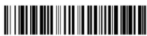
ROTATN2
Upside Down
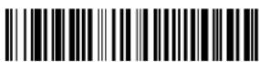
ROTATN1
Vertical, Bottom to Top
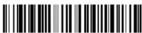
ROTATN3
Vertical, Top to Bottom
The following settings have been developed to enhance scanning in a healthcare environment. These settings are only supported by the Xenon 1900h scanner and Xenon 1902h scanner and base. They allow you to set quickly configure streaming presentation, and to set the scanner and base to quiet modes for scanning that do not disturb resting patients.
Quiet Operations - Combination Codes
The following combination codes program your Xenon healthcare scanner and base for silent or quiet settings using a single programming code. If you wish to program some of these quiet settings individually, refer to Quiet Operations - LED and Volume Settings, beginning on page 145.
Silent Mode with Flashing LED
Scan the following bar code to completely silence the Xenon 1900h scanner or Xenon 1902h scanner and base. The scanner beep, base beep, base and scanner power up beep, and scanner linking sounds are all silenced. When a bar code is scanned, the LED and aimer flash 5 times. Green indicates a good scan, red indicates a bad scan.

Silent Mode with Flashing LED - Cordless Scanner and Base

Silent Mode with Flashing LED - Corded Scanner
Silent Mode with Long LED
Scan the following bar code to completely silence the Xenon 1900h scanner or Xenon 1902h scanner and base. The scanner beep, base beep, base and scanner power up beep, and scanner linking sounds are all silenced. When a bar code is scanned, the LED and aimer remain solidly lit for 1 second. Green indicates a good scan, red indicates a bad scan.
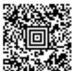
Silent Mode with Long LED - Cordless Scanner and Base

Silent Mode with Long LED - Corded Scanner
Very Low Beeper (Nighttime Mode)
The following bar code silences the base, and sets the scanner for a very low beep when reading bar codes. After scanning this code, the base beep, base and scanner power up beep, and scanner linking sounds are all silenced. When a bar code is scanned, the scanner emits a very soft beep.

Nighttime Mode - Cordless Scanner and Base

Nighttime Mode - Corded Scanner
Low Beeper (Daytime Mode)
The following bar code sets all sounds to on, but at a low volume. The scanner beep, base beep, base and scanner power up beep, and scanner linking sounds are all set to low volume.
Daytime Mode - Cordless Scanner and Base

Daytime Mode - Corded Scanner
To reset your scanner and base to default sounds, refer to Reset the Custom Defaults (page 263).
Quiet Operations - LED and Volume Settings
If you have silenced or muted the scanner and base sounds, you may wish to adjust the visual (LED) indicators for Bluetooth linking sounds, scanning sounds, paging sounds, and out of range alarm sounds.
Linking LED Colors and Sound
Note: This setting is not supported by the Xenon 1900h scanner.
Under normal operations, the scanner chirps when linking to a base or an access point, and the LED on both the base and scanner flash green. If you want to silence all sounds and set both devices to flash red LEDs to indicate the linking status, scan the Red LED Flashes/Silent bar code below. The LEDs flash red while linking, then green to indicate the base and scanner are linked. To return to the default LED colors and sound, scan Green LED Flashes/Sound. Default = Green LED Flashes/Sound.

BEPPAR1.
* Green LED Flashes/Sound

BEPPAR0.
Red LED Flashes/Silent
Number of LED Flashes
If you have silenced the scanner's beeper, you may set the number of times the LED flashes when reading bar codes. Default = 1 LED Flash.
Note: If you have set LED Solid (No Flash) (page 147), to anything but Off, that setting will override the LED Flash settings. In that case, scan the LED Solid Off bar code to turn off this feature, then scan the LED Flash code you wish to use.


LED Flash Rate
If you have silenced the scanner's beeper, you may set the how quickly the LED flashes when reading bar codes. Default = Fast Flash.

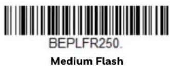

LED Solid (No Flash)
Under normal operations, the scanner's LED flashes once for a good read. You may set the LED to remain on for a length of time after a good read instead of flashing. Default = LED Solid Off (Resume Flash).

BEPLOT0
* LED Solid Off (Resume Flash)
BEPLOT1.
LED Solid 1 Second
BEPLOT3.
LED Solid 3 Seconds

BEPLOT5.
LED Solid 5 Seconds
If you have scanned a bar code and don't want to wait for the LED to turn off, press the trigger a 2nd time and the LED turns off. You can then scan the next bar code.
Page Volume Control
Note: This setting is not supported by the Xenon 1900h scanner.
When you press the Page button on the base or Access Point, the scanners associated with that base or Access Point will begin beeping in response. If you pull the trigger on a scanner that is beeping in response, or press the Page button on the base or Access Point a second time, all associated scanners will stop beeping. The following settings set the paging volume, independent of the volume used when scanning bar codes. Default = Low.
BEPPGV0.
Page Volume Off
BEPPGV1.
* Page Volume Low

BEPPGV2
Page Volume Medium

BEPPGV3.
Page Volume High
Out-of-Range Alarm Volume
Note: This setting is not supported by the Xenon 1900h scanner.
If your scanner is out range of the base, an alarm sounds from both your base and scanner. If your scanner is out range of an Access Point, an alarm sounds from just the scanner. The alarm stops when the scanner is moved closer to the base or Access Point, when the base or Access Point connects to another scanner, or when the alarm duration expires (see Out-of-Range Delay on page 149). The following settings set the Out-of-Range Alarm for the base and the scanner, independent of the volume used when scanning bar codes. Default = Base Alarm Volume Low, Scanner Alarm Volume Low.

BASORV0.
Base Alarm Volume
Off

BT_ORV0.
Scanner Alarm Volume
Off

BASORV1.
* Base Alarm Volume Low

BT_ORV1.
* Scanner Alarm Volume Low
BASORV2
Base Alarm Volume
Medium

BASORV3
Base Alarm Volume High
BT_ORV2.
Scanner Alarm Volume Medium
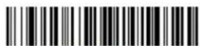
BT_ORV3.
Scanner Alarm Volume High
Out-of-Range Delay
Note: This setting is not supported by the Xenon 1900h scanner.
When using the Out-of-Range Alarm settings, the length of the delay for the alarm is set with an Out-of-Range Delay. When the scanner is out of range of the base or Access Point, the alarm will delay for a set length of time before going off. Set the length (in seconds) for a timeout by scanning the following bar code, then setting the timeout (from 0-3,000 seconds) by scanning digits from the Programming Chart, beginning on page 341, then Save. Default = No Delay.

BT_ORY
Out-of-Range Delay
Prefix/Suffix Overview
When a bar code is scanned, additional information is sent to the host computer along with the bar code data. This group of bar code data and additional, user-defined data is called a “message string.” The selections in this section are used to build the user-defined data into the message string.
Prefix and Suffix characters are data characters that can be sent before and after scanned data. You can specify if they should be sent with all symbologies, or only with specific symbologies. The following illustration shows the breakdown of a message string:

flowchart
graph TD
    A["Prefix"] --> B["Scanned Data"]
    B --> C["Suffix"]
    style A fill:#f9f,stroke:#333
    style B fill:#ccf,stroke:#333
    style C fill:#cfc,stroke:#333
    note1["alpha numeric & control characters"] --> A
    note2["variable length1-11"] --> B
    note3["1-11"] --> C
Points to Keep In Mind
- It is not necessary to build a message string. The selections in this chapter are only used if you wish to alter the default settings. Default prefix = None. Default suffix = None.
- A prefix or suffix may be added or cleared from one symbology or all symbologies.
- You can add any prefix or suffix from the ASCII Conversion Chart (Code Page 1252), beginning on page 330, plus Code I.D. and AIM I.D.
- You can string together several entries for several symbologies at one time.
- Enter prefixes and suffixes in the order in which you want them to appear on the output.
- When setting up for specific symbologies (as opposed to all symbologies), the specific symbology ID value counts as an added prefix or suffix character.
- The maximum size of a prefix or suffix configuration is 200 characters, which includes header information.
Add a Prefix or Suffix:
Step 1. Scan the Add Prefix or Add Suffix symbol (page 153).
Step 2. Determine the 2 digit hex value from the Symbology Charts (beginning on page A-327) for the symbology to which you want to apply the prefix or suffix. For example, for Code 128, Code ID is "j" and Hex ID is "6A".
Step 3. Scan the 2 hex digits from the Programming Chart, beginning on page 341, or scan 9, 9 for all symbologies.
To add the Code I.D., scan 5, C, 8, 0.
To add the AIM I.D., scan 5, C, 8, 1.
To add the serial number, scan 5, C, 8, 8.
To add a backslash (), scan 5, C, 5, C.
Note: When adding a backslash ( ), you must scan 5C twice – once to create the leading backslash and then to create the backslash itself.
Step 4. Repeat Steps 2 and 3 for every prefix or suffix character.
Step 5. Scan Save to exit and save, or scan Discard to exit without saving.
Repeat the steps above to add a prefix or suffix for another symbology.
Example: Add a Tab Suffix to All Symbologies
Step 1. Scan Add Suffix.
Step 2. Scan 9, 9 from the Programming Chart, beginning on page 341 to apply this suffix to all symbologies.
Step 3. Scan 0, 9 from the Programming Chart, beginning on page 341. This corresponds with the hex value for a horizontal tab, shown in the ASCII Conversion Chart (Code Page 1252), beginning on page 330.
Step 4. Scan Save, or scan Discard to exit without saving.
Clear One or All Prefixes or Suffixes
You can clear a single prefix or suffix, or clear all prefixes/suffixes for a symbology. If you have been entering prefixes and suffixes for single symbologies, you can use Clear One Prefix (Suffix) to delete a specific character from a symbology. When you Clear All Prefixes (Suffixes), all the prefixes or suffixes for a symbology are deleted.
Step 1. Scan the Clear One Prefix or Clear One Suffix symbol.
Step 2. Determine the 2 digit Hex value from the Symbology Chart (included in the Symbology Charts, beginning on page 327) for the symbology from which you want to clear the prefix or suffix.
Step 3. Scan the 2 digit hex value from the Programming Chart, beginning on page 341 or scan 9, 9 for all symbologies.
Your change is automatically saved.
Add a Carriage Return Suffix to All Symbologies
Scan the following bar code if you wish to add a carriage return suffix to all symbologies at once. This action first clears all current suffixes, then programs a carriage return suffix for all symbologies.
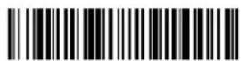
VSUFCR
Add CR Suffix All Symbologies
Prefix Selections
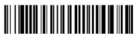
PREBK2.
Add Prefix
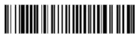
PRECL2
Clear One Prefix

PRECA2
Clear All Prefixes
Suffix Selections

SUFBK2
Add Suffix

SUFCL2
Clear One Suffix

SUFCA2
Clear All Suffixes
Function Code Transmit
When this selection is enabled and function codes are contained within the scanned data, the scanner transmits the function code to the terminal. Charts of these function codes are provided in ASCII Conversion Chart (Code Page 1252), beginning on page 330. When the scanner is in keyboard wedge mode, the scan code is converted to a key code before it is transmitted. Default = Enable.

RMVFNCO
* Enable
RMVFNC1
Disable
Intercharacter, Interfunction, and Intermessage Delays
Some terminals drop information (characters) if data comes through too quickly. Intercharacter, interfunction, and intermessage delays slow the transmission of data, increasing data integrity.
Intercharacter Delay
An intercharacter delay of up to 5000 milliseconds (in 5ms increments) may be placed between the transmission of each character of scanned data. Scan the Intercharacter Delay bar code below, then scan the number of 5ms delays from the Programming Chart, beginning on page 341, then Save.

To remove this delay, scan the Intercharacter Delay bar code, then set the number of delays to 0. Scan the Save bar code from the Programming Chart, beginning on page 341.
Note: Intercharacter delays are not supported in USB serial emulation.
User Specified Intercharacter Delay
An intercharacter delay of up to 5000 milliseconds (in 5ms increments) may be placed after the transmission of a particular character of scanned data. Scan the Delay Length bar code below, then scan the number of 5ms delays from the Programming Chart, beginning on page 341, then Save.
Next, scan the Character to Trigger Delay bar code, then the 2-digit hex value for a printable character to trigger the delay (see Lower ASCII Reference Table, page 331.)

To remove this delay, scan the Delay Length bar code, and set the number of delays to 0. Scan the Save bar code from the Programming Chart, beginning on page 341.
Interfunction Delay
An interfunction delay of up to 5000 milliseconds (in 5ms increments) may be placed between the transmission of each control character in the message string. Scan the Interfunction Delay bar code below, then scan the number of 5ms delays, and the Save bar code from the Programming Chart, beginning on page 341.
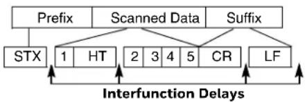
flowchart
graph TD
    A["Prefix"] --> B["STX"]
    C["Scanned Data"] --> D["1"]
    C --> E["HT"]
    C --> F["2"]
    C --> G["3"]
    C --> H["4"]
    C --> I["5"]
    C --> J["CR"]
    C --> K["LF"]
    L["Suffix"] --> M["Interference Delays"]
    M --> A
    M --> C

To remove this delay, scan the Interfunction Delay bar code, then set the number of delays to 0. Scan the Save bar code from the Programming Chart, beginning on page 341.
Intermessage Delay
An intermessage delay of up to 5000 milliseconds (in 5ms increments) may be placed between each scan transmission. Scan the Intermessage Delay bar code below, then scan the number of 5ms delays, and the Save bar code from the Programming Chart, beginning on page 341.
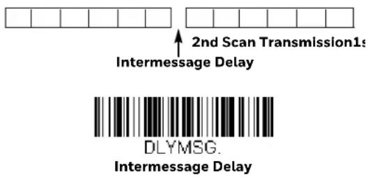
To remove this delay, scan the Intermessage Delay bar code, then set the number of delays to 0. Scan the Save bar code from the Programming Chart, beginning on page 341.
You may use the Data Format Editor to change the scanner's output. For example, you can use the Data Format Editor to insert characters at certain points in bar code data as it is scanned. The selections in the following pages are used only if you wish to alter the output. Default Data Format setting = None.
Normally, when you scan a bar code, it is output automatically. However, when you create a format, you must use a "send" command (see Send Commands on page 160) within the format program to output data.
Multiple formats may be programmed into the scanner. They are stacked in the order in which they are entered. However, the following list presents the order in which formats are applied:
- Specific Terminal ID, Actual Code ID, Actual Length
- Specific Terminal ID, Actual Code ID, Universal Length
- Specific Terminal ID, Universal Code ID, Actual Length
- Specific Terminal ID, Universal Code ID, Universal Length
- Universal Terminal ID, Actual Code ID, Actual Length
- Universal Terminal ID, Actual Code ID, Universal Length
- Universal Terminal ID, Universal Code ID, Actual Length
- Universal Terminal ID, Universal Code ID, Universal Length
The maximum size of a data format configuration is 2000 bytes, which includes header information.
If a bar code is read that fails the first data format, the next data format, if there is one, will be used on the bar code data. If there is no other data format, the raw data is output.
If you have changed data format settings, and wish to clear all formats and return to the factory defaults, scan the Default Data Format code below.

DFMDF3
* Default Data Format
Step 1. Scan the Enter Data Format symbol (page 159).
Determine if this will be your primary data format, or one of 3 alternate formats. This allows you to save a total of 4 different data formats. To program your primary format, scan 0 from the Programming Chart, beginning on page 341. If you are programming an alternate format, scan 1, 2, or 3, depending on which alternate format you are programming. (See Primary/Alternate Data Formats on page 175 for further information.)
Step 3. Terminal Type
Refer to Terminal ID Table (page 160) and locate the Terminal ID number for your PC. Scan three numeric bar codes from the Programming Chart, beginning on page 341, to program the scanner for your terminal ID (you must enter 3 digits). For example, scan 0 0 3 for an AT wedge.
Note: 099 indicates all terminal types.
Step 4. Code I.D.
In the Symbology Charts, beginning on page 327, find the symbology to which you want to apply the data format. Locate the Hex value for that symbology and scan the 2 digit hex value from the Programming Chart, beginning on page 341.
If you wish to create a data format for all symbologies, with the exception of some specific symbologies, refer to B8 (page 173).
If you are creating a data format for Batch Mode Quantity, use 35 for the Code I.D.
Note: 99 indicates all symbologies.
Step 5. Length
Specify what length (up to 9999 characters) of data will be acceptable for this symbology. Scan the four digit data length from the Programming Chart, beginning on page 341. For example, 50 characters is entered as 0050.
Note: 9999 indicates all lengths.
Step 6. Editor Commands
Refer to Data Format Editor Commands (page 160). Scan the symbols that represent the command you want to enter.
Step 7. Scan Save to save your data format, or Discard to exit without saving your changes.

DFMBK3.
Enter Data Format

MNUSAV.
Save
MNUABT
Discard
Other Programming Selections
This deletes one data format for one symbology. If you are clearing the primary format, scan 0 from the Programming Chart, beginning on page 341. If you are clearing an alternate format, scan 1, 2, or 3, depending on the format you are clearing. Scan the Terminal Type and Code I.D. (see Symbology Charts on page 327), and the bar code data length for the specific data format that you want to delete. All other formats remain unaffected.
This clears all data formats.
- Save
Exit and save your data format changes.
- Discard
Exit without saving any data format changes.

DFMCL3
Clear One Data Format

DFMCA3
Clear All Data Formats

MNUSAV.
Save
MNUABT
Discard
Terminal ID Table
| Terminal Model(s) Terminal ID |
| USB PC keyboard (HID) 124 |
| Mac Keyboard 125 |
| PC Keyboard (Japanese) 134 |
| Serial (COM driver required) 130 |
| HID POS 131 |
| USB SurePOS Handheld 128 |
| USB SurePOS Tabletop | 129 |
| Serial | RS232 TTL | 000 |
| RS232 True | 000 |
| RS485 (IBM-HHBCR 1+2, 46xx) | 051 |
| Keyboard | PS2 compatibles | 003 |
| AT compatibles | 002 |
When working with the Data Format Editor, a virtual cursor is moved along your input data string. The following commands are used to both move this cursor to different positions, and to select, replace, and insert data into the final output.
Send Commands
Send all characters
F1 Include in the output message all of the characters from the input message, starting from current cursor position, followed by an insert character. Syntax = F1xx where xx stands for the insert character's hex value for its ASCII code. Refer to the ASCII Conversion Chart (Code Page 1252), beginning on page 330 for decimal, hex and character codes.
Send a number of characters
F2 Include in the output message a number of characters followed by an insert character. Start from the current cursor position and continue for "nn" characters or through the last character in the input message, followed by character "xx." Syntax = F2nnxx where nn stands for the numeric value (00-99) for the number of characters, and xx stands for the insert character's hex value for its ASCII code. Refer to the ASCII Conversion Chart (Code Page 1252), beginning on page 330 for decimal, hex and character codes.
F2 Example: Send a number of characters

Send the first 10 characters from the bar code above, followed by a carriage return. Command string: F2100D
F2 is the "Send a number of characters" command
10 is the number of characters to send
OD is the hex value for a CR
The data is output as: 1234567890
F2 and F1 Example: Split characters into 2 lines
Send the first 10 characters from the bar code above, followed by a carriage return, followed by the rest of the characters.
Command string: F2100DF10D
F2 is the "Send a number of characters" command
10 is the number of characters to send for the first line
OD is the hex value for a CR
F1 is the "Send all characters" command
OD is the hex value for a CR
The data is output as:
1234567890
ABCDEFGHIJ
Send all characters up to a particular character
F3 Include in the output message all characters from the input message, starting with the character at the current cursor position and continuing to, but not including, the search character "ss," followed by an insert character. The cursor is moved forward to the "ss" character. Syntax = F3ssxx where ss stands for the search character's hex value for its ASCII code, and xx stands for the insert character's hex value for its ASCII code.
Refer to the ASCII Conversion Chart (Code Page 1252), beginning on page 330 for decimal, hex and character codes.
F3 Example: Send all characters up to a particular character

Using the bar code above, send all characters up to but not including “D,” followed by a carriage return.
Command string: F3440D
F3 is the "Send all characters up to a particular character" command
44 is the hex value for a 'D"
OD is the hex value for a CR
The data is output as:
1234567890ABC
Send all characters up to a string
B9 Include in the output message all characters from the input message, starting with the character at the current cursor position and continuing to, but not including, the search string "s...s." The cursor is moved forward to the beginning of the "s...s" string. Syntax = B9nnnns...s where nnnn stands for the length of the string, and s...s stands for the string to be matched. The string is made up of hex values for the characters in the string. Refer to the ASCII Conversion Chart (Code Page 1252), beginning on page 330 for decimal, hex and character codes.
B9 Example: Send all characters up to a defined string

Using the bar code above, send all characters up to but not including "AB."
Command string: B900024142
B9 is the "Send all characters up to a string" command
0002 is the length of the string (2 characters)
41 is the hex value for A
42 is the hex value for B
The data is output as: 1234567890
Send all but the last characters
E9 Include in the output message all but the last "nn" characters, starting from the current cursor position. The cursor is moved forward to one position past the last input message character included. Syntax = E9nn where nn stands for the numeric value (00-99) for the number of characters that will not be sent at the end of the message.
Insert a character multiple times
F4 Send "xx" character "nn" times in the output message, leaving the cursor in the current position. Syntax = F4xxnn where xx stands for the insert character's hex value for its ASCII code, and nn is the numeric value (00-99) for the number of times it should be sent. Refer to the ASCII Conversion Chart (Code Page 1252), beginning on page 330 for decimal, hex and character codes.
E9 and F4 Example: Send all but the last characters, followed by 2 tabs

Send all characters except for the last 8 from the bar code above, followed by 2 tabs.
Command string: E908F40902
E9 is the "Send all but the last characters" command
08 is the number of characters at the end to ignore
F4 is the "Insert a character multiple times" command
09 is the hex value for a horizontal tab
02 is the number of times the tab character is sent
The data is output as: 1234567890AB
Insert a string
BA Send "ss" string of "nn" length in the output message, leaving the cursor in the current position. Syntax = BAnnnns...s where nnnn stands for the length of the string, and s...s stands for the string. The string is made up of hex values for the characters in the string. Refer to the ASCII Conversion Chart (Code Page 1252), beginning on page 330 for decimal, hex and character codes.
B9 and BA Example: Look for the string "AB" and insert 2 asterisks (**)

Using the bar code above, send all characters up to but not including "AB." Insert 2 asterisks at that point, and send the rest of the data with a carriage return after.
Command string: B900024142BA00022A2AF10D
B9 is the "Send all characters up to a string" command
0002 is the length of the string (2 characters)
41 is the hex value for A
42 is the hex value for B
BA is the "Insert a string" command
0002 is the length of the string to be added (2 characters)
2A is the hex value for an asterisk (*)
2A is the hex value for an asterisk (*)
F1 is the "Send all characters" command
OD is the hex value for a CR
The data is output as:
1234567890**ABCDEFGHIJ
Insert symbology name
B3 Insert the name of the bar code's symbology in the output message, without moving the cursor. Only symbologies with a Honeywell ID are included (see Symbology Charts on page 327). Refer to the ASCII Conversion Chart (Code Page 1252), beginning on page 330 for decimal, hex and character codes.
Insert bar code length
B4 Insert the bar code's length in the output message, without moving the cursor. The length is expressed as a numeric string and does not include leading zeros.
B3 and B4 Example: Insert the symbology name and length

Send the symbology name and length before the bar code data from the bar code above. Break up these insertions with spaces. End with a carriage return.
Command string: B3F42001B4F42001F10D
B3 is the "Insert symbology name" command
F4 is the "Insert a character multiple times" command
20 is the hex value for a space
01 is the number of times the space character is sent
B4 is the "Insert bar code length" command
F4 is the "Insert a character multiple times" command
20 is the hex value for a space
01 is the number of times the space character is sent
F1 is the "Send all characters" command
OD is the hex value for a CR
The data is output as:
Code128 20 1234567890ABCDEFGHIJ
Insert key strokes
B5 Insert a key stroke or combination of key strokes. Key strokes are dependent on your keyboard (see Keyboard Key References on page 337). Any key can be inserted, including arrows and functions. Syntax = 5CB5xxssnn where xx is the number of keys pressed (without key modifiers), ss is the key modifier from the table below, and nn is the key number from the Keyboard Key References, page 337.
| Key Modifiers Hex |
| No Key Modifier 00 | |
| Shift Left 01 | |
| Shift Right 02 | |
| Alt Left 04 | |
| Alt Right 08 | |
| Control Left | 10 |
| Control Right | 20 |
- For example, B501021F inserts an “A” on a 104 key, U.S. style keyboard. B5 = the command, 01 = number of key press events (without the key modifier), 02 is the key modifier for Shift Right, and 1F is the “a” key. If a lower case “a” were to be inserted, B501001F would be entered.
If there are three keystrokes, the syntax would change from B5xxssnn for one keystroke to B5xxssnnssnnssnn. An example that would insert "abc" is as follows: B503001F00320030F833.
Note: Key modifiers can be added together when needed. The sum is converted to hexadecimals.
Example: Control Left+Shift Left = 17, converted to hexadecimal = 11.
Move Commands
Move the cursor forward a number of characters
F5 Move the cursor ahead "nn" characters from current cursor position.
Syntax = F5nn where nn is the numeric value (00-99) for the number of characters the cursor should be moved ahead.
F5 Example: Move the cursor forward and send the data

1234567890ABCDEFGHIJ
Move the cursor forward 3 characters, then send the rest of the bar code data from the bar code above. End with a carriage return.
Command string: F503F10D
F5 is the "Move the cursor forward a number of characters" command
03 is the number of characters to move the cursor
F1 is the "Send all characters" command
OD is the hex value for a CR
The data is output as:
4567890ABCDEFGHIJ
Move the cursor backward a number of characters
F6 Move the cursor back "nn" characters from current cursor position.
Syntax = F6nn where nn is the numeric value (00-99) for the number of characters the cursor should be moved back.
Move the cursor to the beginning
F7 Move the cursor to the first character in the input message. Syntax = F7.
FE and F7 Example: Manipulate bar codes that begin with a 1

Search for bar codes that begin with a 1. If a bar code matches, move the cursor back to the beginning of the data and send 6 characters followed by a carriage return. Using the bar code above:
Command string: FE31F7F2060D
FE is the "Compare characters" command
31 is the hex value for 1
F7 is the "Move the cursor to the beginning" command
F2 is the "Send a number of characters" command
06 is the number of characters to send
OD is the hex value for a CR
The data is output as:
123456
Move the cursor to the end
EA Move the cursor to the last character in the input message. Syntax = EA.
Search Commands
Search forward for a character
F8 Search the input message forward for "xx" character from the current cursor position, leaving the cursor pointing to the "xx" character. Syntax = F8xx where xx stands for the search character's hex value for its ASCII code.
Refer to the ASCII Conversion Chart (Code Page 1252), beginning on page 330 for decimal, hex and character codes.
F8 Example: Send bar code data that starts after a particular character

Search for the letter "D" in bar codes and send all the data that follows, including the "D." Using the bar code above:
Command string: F844F10D
F8 is the "Search forward for a character" command
44 is the hex value for "D"
F1 is the "Send all characters" command
OD is the hex value for a CR
The data is output as:
DEFGHIJ
Search backward for a character
F9 Search the input message backward for "xx" character from the current cursor position, leaving the cursor pointing to the "xx" character. Syntax = F9xx where xx stands for the search character's hex value for its ASCII code.
Refer to the ASCII Conversion Chart (Code Page 1252), beginning on page 330 for decimal, hex and character codes.
Search forward for a string
B0 Search forward for "s" string from the current cursor position, leaving cursor pointing to "s" string. Syntax = B0nnnnS where nnnn is the string length (up to 9999), and S consists of the ASCII hex value of each character in the match string. For example, B0000454657374 will search forward for the first occurrence of the 4 character string "Test."
Refer to the ASCII Conversion Chart (Code Page 1252), beginning on page 330 for decimal, hex and character codes.
B0 Example: Send bar code data that starts after a string of characters

Search for the letters "FGH" in bar codes and send all the data that follows, including "FGH." Using the bar code above:
Command string: B00003464748F10D
BO is the "Search forward for a string" command
0003 is the string length (3 characters)
46 is the hex value for "F"
47 is the hex value for "G"
48 is the hex value for "H"
F1 is the "Send all characters" command
OD is the hex value for a CR
The data is output as:
FGHIJ
Search backward for a string
B1 Search backward for "s" string from the current cursor position, leaving cursor pointing to "s" string. Syntax = B1nnnnS where nnnn is the string length (up to 9999), and S consists of the ASCII hex value of each character in the match string. For example, B1000454657374 will search backward for the first occurrence of the 4 character string "Test."
Refer to the ASCII Conversion Chart (Code Page 1252), beginning on page 330 for decimal, hex and character codes.
Search forward for a non-matching character
E6 Search the input message forward for the first non-“xx” character from the current cursor position, leaving the cursor pointing to the non-“xx” character. Syntax = E6xx where xx stands for the search character's hex value for its ASCII code. Refer to the ASCII Conversion Chart (Code Page 1252), beginning on page 330 for decimal, hex and character codes.
E6 Example: Remove zeros at the beginning of bar code data

This example shows a bar code that has been zero filled. You may want to ignore the zeros and send all the data that follows. E6 searches forward for the first character that is not zero, then sends all the data after, followed by a carriage return. Using the bar code above:
Command string: E630F10D
E6 is the "Search forward for a non-matching character" command
30 is the hex value for 0
F1 is the "Send all characters" command
OD is the hex value for a CR
The data is output as:
37692
Search backward for a non-matching character
E7 Search the input message backward for the first non-“xx” character from the current cursor position, leaving the cursor pointing to the non-“xx” character. Syntax = E7xx where xx stands for the search character's hex value for its ASCII code. Refer to the ASCII Conversion Chart (Code Page 1252), beginning on page 330 for decimal, hex and character codes.
Miscellaneous Commands
Suppress characters
FB Suppress all occurrences of up to 15 different characters, starting at the current cursor position, as the cursor is advanced by other commands. When the FC command is encountered, the suppress function is terminated. The cursor is not moved by the FB command.
Syntax = FBnnxxyy ..zz where nn is a count of the number of suppressed characters in the list, and xxyy .. zz is the list of characters to be suppressed.
FB Example: Remove spaces in bar code data
This example shows a bar code that has spaces in the data. You may want to remove the spaces before sending the data. Using the bar code above:
Command string: FB0120F10D
FB is the "Suppress characters" command
01 is the number of character types to be suppressed
20 is the hex value for a space
F1 is the "Send all characters" command
OD is the hex value for a CR
The data is output as:
34567890
Stop suppressing characters
FC Disables suppress filter and clear all suppressed characters. Syntax = FC.
Replace characters
E4 Replaces up to 15 characters in the output message, without moving the cursor. Replacement continues until the E5 command is encountered. Syntax = E4nnxx_1xx_2yy_1yy_2...zz_1zz_2 where nn is the total count of the number of characters in the list (characters to be replaced plus replacement characters); xx _1 defines characters to be replaced and xx _2 defines replacement characters, continuing through zz _1 and zz _2 .
E4 Example: Replace zeros with CRs in bar code data

If the bar code has characters that the host application does not want included, you can use the E4 command to replace those characters with something else. In this example, you will replace the zeros in the bar code above with carriage returns.
Command string: E402300DF10D
E4 is the "Replace characters" command
02 is the total count of characters to be replaced, plus the replacement characters (0 is replaced by CR, so total characters = 2)
30 is the hex value for 0
OD is the hex value for a CR (the character that will replace the O)
F1 is the "Send all characters" command
OD is the hex value for a CR
The data is output as:
1234
5678
ABC
Stop replacing characters
E5 Terminates character replacement. Syntax = E5.
Compare characters
FE Compare the character in the current cursor position to the character "xx." If characters are equal, move the cursor forward one position. Syntax = FExx where xx stands for the comparison character's hex value for its ASCII code.
Refer to the ASCII Conversion Chart (Code Page 1252), beginning on page 330 for decimal, hex and character codes.
Compare string
B2 Compare the string in the input message to the string "s." If the strings are equal, move the cursor forward past the end of the string. Syntax = B2nnnnS where nnnn is the string length (up to 9999), and S consists of the ASCII hex value of each character in the match string. For example, B2000454657374 will compare the string at the current cursor position with the 4 character string "Test."
Refer to the ASCII Conversion Chart (Code Page 1252), beginning on page 330 for decimal, hex and character codes.
Check for a number
EC Check to make sure there is an ASCII number at the current cursor position. The format is aborted if the character is not numeric.
EC Example: Only output the data if the bar code begins with a number
If you want only data from bar codes that begin with a number, you can use EC to check for the number.
Command string: ECF10D
EC is the "Check for a number" command
F1 is the "Send all characters" command
OD is the hex value for a CR
If this bar code is read, AB1234 the next data format, if there is one, will
be used on the data. If there is no other format, the format fails and the raw data is output as AB1234.
If this bar code is read: the data is output as: 1234AB
1234AB
Check for non-numeric character
ED Check to make sure there is a non-numeric ASCII character at the current cursor position. The format is aborted if the character is numeric.
ED Example: Only output the data if the bar code begins with a letter
If you want only data from bar codes that begin with a letter, you can use ED to check for the letter.
Command string: EDF10D
ED is the "Check for a non-numeric character" command
F1 is the "Send all characters" command
OD is the hex value for a CR
If this bar code is read, the next data format, if there is one, will 1234AB
be used on this data. If there is no other format, the format fails and the raw data is output as 1234AB.
If this bar code is read: the data is output as: AB1234
AB1234
Insert a delay
EF Inserts a delay of up to 49,995 milliseconds (in multiples of 5), starting from the current cursor position. Syntax = EFnnnn where nnnn stands for the delay in 5ms increments, up to 9999. This command can only be used with keyboard emulation.
Discard Data
B8 Discards types of data. For example, you may want to discard Code 128 bar codes that begin with the letter A. In step 4 (page 158), select 6A (for Code 128), and in step 5, select 9999 (for all lengths). Enter FE41B8 to compare and discard Code 128 bar codes that begin with the letter A. Syntax = B8.
Note: The B8 command must be entered after all other commands.
The Data Format must be Required (see page 173) in order for the B8 command to work.
If Data Format is On, but Not Required (page 174), bar code data that meets the B8 format is scanned and output as usual.
Because the data format needs to be On and Required (page 174) for the B8 command, you must input data formats for all bar codes you wish to discard as well as all bar codes you wish to output.
Other data format settings impact the B8 command. If Data Format Non-Match Error Tone is On (page 174), the scanner emits an error tone. If Data format Non-Match Error Tone is Off, the code is disabled for reading and no tone is sounded.
When Data Formatter is turned Off, the bar code data is output to the host as read, including prefixes and suffixes.

Data Formatter Off
You may wish to require the data to conform to a data format you have created and saved. The following settings can be applied to your data format:
- Data Formatter On, Not Required, Keep Prefix/Suffix
Scanned data is modified according to your data format, and prefixes and suffixes are transmitted.
- Data Formatter On, Not Required, Drop Prefix/Suffix
Scanned data is modified according to your data format. If a data format is found for a particular symbol, those prefixes and suffixes are not transmitted. If a data format is not found for that symbol, the prefixes and suffixes are transmitted.
- Data Format Required, Keep Prefix/Suffix
Scanned data is modified according to your data format, and prefixes and suffixes are transmitted. Any data that does not match your data format requirements generates an error tone and the data in that bar code is not transmitted. If you wish to process this type of bar code without generating an error tone, see Data Format Non-Match Error Tone.
- Data Format Required, Drop Prefix/Suffix
Scanned data is modified according to your data format. If a data format is found for a particular symbol, those prefixes and suffixes are not transmitted.
Any data that does not match your data format requirements generates an error tone. If you wish to process this type of bar code without generating an error tone, see Data Format Non-Match Error Tone.
Choose one of the following options. Default = Data Formatter On, Not Required, Keep Prefix/Suffix.

DFM EN1
* Data Formatter On,
Not Required,
Keep Prefix/Suffix

DFM_EN3
Data Formatter On,
Not Required,
Drop Prefix/Suffix

DFM_EN2
Data Format Required,
Keep Prefix/Suffix

DFM_EN4.
Data Format Required,
Drop Prefix/Suffix
When a bar code is encountered that doesn't match your required data format, the scanner normally generates an error tone. However, you may want to continue scanning bar codes without hearing the error tone. If you scan the Data Format
Non-Match Error Tone Off bar code, data that doesn't conform to your data format is not transmitted, and no error tone will sound. If you wish to hear the error tone when a non-matching bar code is found, scan the Data Format Non-Match
Error Tone On bar code. Default = Data Format Non-Match Error Tone On.

DFMDECO
* Data Format Non-Match Error
Tone On

DFMDEC1
Data Format Non-Match
Error Tone Off
You can save up to four data formats, and switch between these formats. Your primary data format is saved under 0. Your other three formats are saved under 1, 2, and 3. To set your device to use one of these formats, scan one of the bar codes below.
ALTFNMO.
Primary Data Format

ALTFNM1
Data Format 1

ALTFNM2
Data Format 2

ALTFNM3
Data Format 3
You can also switch between data formats for a single scan. The next bar code is scanned using an alternate data format, then reverts to the format you have selected above (either Primary, 1, 2, or 3).
For example, you may have set your device to the data format you saved as Data Format 3. You can switch to Data Format 1 for a single trigger pull by scanning the Single Scan-Data Format 1 bar code below. The next bar code that is scanned uses Data Format 1, then reverts back to Data Format 3.

VSAF_0.
Single Scan-Primary
Data Format

VSAF 1.
Single Scan-Data Format 1
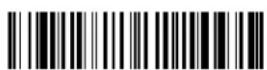
VSAF_2.
Single Scan-Data Format 2
This programming section contains the following menu selections. Refer to Chapter 12 for settings and defaults.
- All Symbologies • Interleaved 2 of 5
- Az t e c C o d e • K o r e a P o s t
• China Post (Hong Kong 2 of 5) • Label Code
- Chinese Sensible (Han Xin) Code • Matrix 2 of 5
- Codabar • MaxiCode
• Codablock A • MicroPDF417
- Codablock F • MSI
• C o d e 1 1 • N E C 2 o f 5
• Code 128 • Postal Codes - 2D
• Code 32 Pharmaceutical (PARAF) • Postal Codes - Linear
• C o d e 3 9 • P D F 4 1 7
• C o d e 9 3 • G S 1 D a t a B a r O m n i d i
- Data Matrix • QR Code
• E A N / J A N - 1 3 • Straight 2 of 5 IATA (two-bar start/stop)
• E A N / J A N - 8 • Straight 2 of 5 Industrial (three-bar start/stop)
• GS1 Composite Codes • TCIF Linked Code 39 (TLC39)
- GS1 DataBar Expanded
- Telepen
- GS1 DataBar Limited
- Trioptic Code
- GS1 DataBar Omnidirectional
- UPC-A
• G S 1 E m u l a t i o n • UPC-A/EAN-13 with Extended Coupon Code
- GS1-128
- UPC-E0
- UPC-E1
All Symbologies
If you want to decode all the symbologies allowable for your scanner, scan the All Symbologies On code. If on the other hand, you want to decode only a particular symbology, scan All Symbologies Off followed by the On symbol for that particular symbology.
Note: Scanner performance may reduce by scanning All Symbologies On. Only scan All Symbologies On when needed.


Note: When All Symbologies On is scanned, 2D Postal Codes are not enabled. 2D Postal Codes must be enabled separately.
Message Length Description
You are able to set the valid reading length of some of the bar code symbologies. You may wish to set the same value for minimum and maximum length to force the scanner to read fixed length bar code data. This helps reduce the chances of a mis-read.
Example: Decode only those bar codes with a count of 9-20 characters.
Min. length = 09
Max. length = 20
Example: Decode only those bar codes with a count of 15 characters.
Min. length = 15
Max. length = 15
For a value other than the minimum and maximum message length defaults, scan the bar codes included in the explanation of the symbology, then scan the digit value of the message length and Save bar codes from the Programming Chart, beginning on page 341. The minimum and maximum lengths and the defaults are included with the respective symbologies.
Codabar

CBRDFT
Codabar On/Off
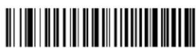
CBRENA1.
* On
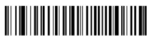
CBRENAD.
Off
Codabar Start/Stop Characters
Start/Stop characters identify the leading and trailing ends of the bar code. You may either transmit, or not transmit Start/Stop characters. Default = Don't Transmit.

CBRSSX1
Transmit
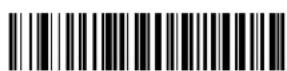
CBRSSXD
* Don't Transmit
Codabar Check Character
Codabar check characters are created using different "modulos." You can program the scanner to read only Codabar bar codes with Modulo 16 check characters.
Default = No Check Character.
No Check Character indicates that the scanner reads and transmits bar code data with or without a check character.
When Check Character is set to Validate and Transmit, the scanner will only read Codabar bar codes printed with a check character, and will transmit this character at the end of the scanned data.
When Check Character is set to Validate, but Don't Transmit, the unit will only read Codabar bar codes printed with a check character, but will not transmit the check character with the scanned data.
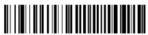
CBRCK20
* No Check Character

CBRCK21
Validate Modulo 16, but Don't Transmit

CBRCK22
Validate Modulo 16 and Transmit
Codabar Concatenation
Codabar supports symbol concatenation. When you enable concatenation, the scanner looks for a Codabar symbol having a "D" start character, adjacent to a symbol having a "D" stop character. In this case the two messages are concatenated into one with the "D" characters omitted.

Select Require to prevent the scanner from decoding a single "D" Codabar symbol without its companion. This selection has no effect on Codabar symbols without Stop/Start D characters.
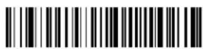
CBRCCT1
On

CBRCCTO
* Off
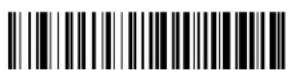
CBRCCT2
Require
Codabar Message Length
Scan the bar codes below to change the message length. Refer to Message Length Description (page 178) for additional information. Minimum and Maximum lengths = 2-60. Minimum Default = 4, Maximum Default = 60.

CBRMIN.
Minimum Message Length

CBRMAX
Maximum Message Length
Code 39
< Default All Code 39 Settings >

C39DFT.
Code 39 On/Off

C39ENA1
* On
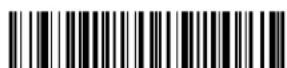
C39ENAO.
Off
If you are reading Code 39 bar codes, Codablock A should remain disabled. If you are enabling Codablock A (see Codablock A on page 213), you should disable Code 39.
Code 39 Start/Stop Characters
Start/Stop characters identify the leading and trailing ends of the bar code. You may either transmit, or not transmit Start/Stop characters. Default = Don't Transmit.
C39SSX1
Transmit
Code 39 Check Character
No Check Character indicates that the scanner reads and transmits bar code data with or without a check character.
When Check Character is set to Validate, but Don't Transmit, the unit only reads Code 39 bar codes printed with a check character, but will not transmit the check character with the scanned data.
When Check Character is set to Validate and Transmit, the scanner only reads Code 39 bar codes printed with a check character, and will transmit this character at the end of the scanned data. Default = No Check Character.
C39CK20
* No Check Character

C39CK21
Validate, but Don't Transmit

C39CK22
Validate and Transmit
Code 39 Message Length
Scan the bar codes below to change the message length. Refer to Message Length Description (page 178) for additional information. Minimum and Maximum lengths = 0-48. Minimum Default = 0, Maximum Default = 48.

C39MIN
Minimum Message Length
C39MAX
Maximum Message Length
Code 39 Append
This function allows the scanner to append the data from several Code 39 bar codes together before transmitting them to the host computer. When the scanner encounters a Code 39 bar code with the append trigger character(s), it buffers Code 39 bar codes until it reads a Code 39 bar code that does not have the append trigger. The data is then transmitted in the order in which the bar codes were read (FIFO). Default = Off.


Code 32 Pharmaceutical (PARAF)
Code 32 Pharmaceutical is a form of the Code 39 symbology used by Italian pharmacies. This symbology is also known as PARAF.
Note: Trioptic Code (page 212) must be turned off while scanning Code 32 Pharmaceutical codes.

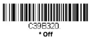
Full ASCII
If Full ASCII Code 39 decoding is enabled, certain character pairs within the bar code symbol will be interpreted as a single character. For example: \$V will be decoded as the ASCII character SYN, and /C will be decoded as the ASCII character #. Default = Off.
| Full ASCII Table |
| NUL %U | DLE P | SP | SPACE | 0 | 0 | @ | %V | P | P | | %W | p | +P | |
| SOHA | DC1 Q | ! | /A | 1 | 1 | A | A | Q | Q | a | +A | q | +Q | |
| STXB | DC2 R | “ | /B | 2 | 2 | B | B | R | R | b | +B | r | +R | |
| ETXC | DC3 S | # | /C | 3 | 3 | C | C | S | S | c | +C | s | +S | |
| EOTD | DC4 T | | /D | 4 | 4 | D | D | T | T | d | +D | t | +T | |
| ENQ E | NAKU | % | /E | 5 | 5 | E | E | U | U | e | +E | u | +U | |
| ACK F | SYNV | & | /F | 6 | 6 | F | F | V | V | f | +F | v | +V | |
| Full ASCII Table (Continued) |
| BEL G | ETBW | * | /G | 7 | 7 | G | G | W | W | g | +G | w | +W | |
| BS H | CANX | ( | /H | 8 | 8 | H | H | X | X | h | +H | x | +X | |
| HT I | EMY | ) | /I | 9 | 9 | I | I | Y | Y | i | +I | y | +Y | |
| LF J | SUBZ | * | /J | : | /Z | J | J | Z | Z | j | +J | z | +Z | |
| VT K | ESC %A | + | /K | ; | %F | K | K | [ | %K | k | +K | | %P | |
| FFL | FS %B | , | /L | < | %G | L | L | \ | %L | l | +L | | | %Q | |
| CR M | GS %C | - | - | = | %H | M | M | ] | %M | m | +M | | %R | |
| SON | RS %D | . | . | > | %I | N | N | ^ | %N | n | +N | ~ | %S | |
| SI $O | US %E | / | /O | ? | %J | O | O | _ | %O | o | +O | DEL %T | |
Character pairs /M and /N decode as a minus sign and period respectively. Character pairs /P through /Y decode as 0 through 9.

C39ASC1
Full ASCII On
C39ASCO
* Full ASCII Off
Code 39 Code Page
Code pages define the mapping of character codes to characters. If the data received does not display with the proper characters, it may be because the bar code being scanned was created using a code page that is different from the one the host program is expecting. If this is the case, scan the bar code below, select the code page with which the bar codes were created (see ISO 2022/ISO 646 Character Replacements on page 334), and scan the value and the Save bar code from the Programming Chart, beginning on page 341. The data characters should then appear properly.

C39DCP
Code 39 Code Page
Interleaved 2 of 5
< Default All Interleaved 2 of 5 Settings >

Interleaved 2 of 5 On/Off


Check Digit
No Check Digit indicates that the scanner reads and transmits bar code data with or without a check digit.
When Check Digit is set to Validate, but Don't Transmit, the unit only reads Inter-leaved 2 of 5 bar codes printed with a check digit, but will not transmit the check digit with the scanned data.
When Check Digit is set to Validate and Transmit, the scanner only reads Inter-leaved 2 of 5 bar codes printed with a check digit, and will transmit this digit at the end of the scanned data. Default = No Check Digit.

Interleaved 2 of 5 Message Length
Scan the bar codes below to change the message length. Refer to Message Length Description (page 178) for additional information. Minimum and Maximum lengths = 2-80. Minimum Default = 6, Maximum Default = 80.

Minimum Message Length

Maximum Message Length
NEC 2 of 5
< Default All NEC 2 of 5 Settings >
NEC 2 of 5 On/Off

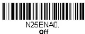
Check Digit
No Check Digit indicates that the scanner reads and transmits bar code data with or without a check digit.
When Check Digit is set to Validate, but Don't Transmit, the unit only reads NEC 2 of 5 bar codes printed with a check digit, but will not transmit the check digit with the scanned data.
When Check Digit is set to Validate and Transmit, the scanner only reads NEC 2 of 5 bar codes printed with a check digit, and will transmit this digit at the end of the scanned data. Default = No Check Digit.
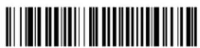
N25CK20
* No Check Digit

N25CK21
Validate, but Don't Transmit

N25CK22
Validate and Transmit
NEC 2 of 5 Message Length
Scan the bar codes below to change the message length. Refer to Message Length Description (page 178) for additional information. Minimum and Maximum lengths = 2-80. Minimum Default = 4, Maximum Default = 80.
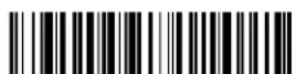
N25MIN
Minimum Message Length
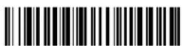
N25MAX
Maximum Message Length
Code 93
< Default All Code 93 Settings >

C93DFT.
Code 93 On/Off

C93ENA1
* On
Code 93 Message Length
Scan the bar codes below to change the message length. Refer to Message Length Description (page 178) for additional information. Minimum and Maximum lengths = 0-80. Minimum Default = 0, Maximum Default = 80.

Code 93 Append
This function allows the scanner to append the data from several Code 93 bar codes together before transmitting them to the host computer. When this function is enabled, the scanner stores those Code 93 bar codes that start with a space (excluding the start and stop symbols), and does not immediately transmit the data. The scanner stores the data in the order in which the bar codes are read, deleting the first space from each. The scanner transmits the appended data when it reads a Code 93 bar code that starts with a character other than a space. Default = Off.


Code 93 Code Page
Code pages define the mapping of character codes to characters. If the data received does not display with the proper characters, it may be because the bar code being scanned was created using a code page that is different from the one the host program is expecting. If this is the case, scan the bar code below, select the code page with which the bar codes were created (see ISO 2022/ISO 646
Character Replacements on page 334), and scan the value and the Save bar code from the Programming Chart, beginning on page 341. The data characters should then appear properly.
C93DCP
Code 93 Code Page
Straight 2 of 5 Industrial (three-bar start/stop)
R25DFT
Straight 2 of 5 Industrial On/Off

R25ENA1
On
R25ENAD.
* Off
Straight 2 of 5 Industrial Message Length
Scan the bar codes below to change the message length. Refer to Message Length Description (page 178) for additional information. Minimum and Maximum lengths = 1-48. Minimum Default = 4, Maximum Default = 48.

R25MIN.
Minimum Message Length

R25MAX
Maximum Message Length
Straight 2 of 5 IATA (two-bar start/stop)

Straight 2 of 5 IATA On/Off


Straight 2 of 5 IATA Redundancy
If you are encountering errors when reading Straight 2 of 5 IATA bar codes, you may want to adjust the redundancy count. Redundancy adjusts the number of times a bar code is decoded before transmission, which may reduce the number of errors. Note that the higher the redundancy count, the longer it will take to decode the bar code. To adjust the redundancy, scan the Straight 2 of 5 IATA Redundancy bar code below, then scan a redundancy count between 0 and 10 on the Programming Chart, beginning on page 341. Then scan the Save bar code. Default = 0.

Straight 2 of 5 IATA Message Length
Scan the bar codes below to change the message length. Refer to Message Length Description (page 178) for additional information. Minimum and Maximum lengths = 1-48. Minimum Default = 4, Maximum Default = 48.


Matrix 2 of 5
Matrix 2 of 5 On/Off

Matrix 2 of 5 Message Length
Scan the bar codes below to change the message length. Refer to Message Length Description (page 178) for additional information. Minimum and Maximum lengths = 1-80. Minimum Default = 4, Maximum Default = 80.

Code 11
Code 11 On/Off
Check Digits Required
This option sets whether 1 or 2 check digits are required with Code 11 bar codes. Default = Two Check Digits.

Code 11 Message Length
Scan the bar codes below to change the message length. Refer to Message Length Description (page 178) for additional information. Minimum and Maximum lengths = 1-80. Minimum Default = 4, Maximum Default = 80.


Code 128
Code 128 On/Off
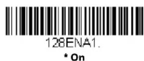

If you are reading Code 128 bar codes, Codablock F should remain disabled. If you are enabling Codablock F (see Codablock F on page 214), you should disable Code 128.
ISBT 128 Concatenation
In 1994 the International Society of Blood Transfusion (ISBT) ratified a standard for communicating critical blood information in a uniform manner. The use of ISBT formats requires a paid license. The ISBT 128 Application Specification describes 1) the critical data elements for labeling blood products, 2) the current recommendation to use Code 128 due to its high degree of security and its space-efficient design, 3) a variation of Code 128 that supports concatenation of neighboring symbols, and 4) the standard layout for bar codes on a blood product label. Use the bar codes below to turn concatenation on or off. Default = Off.


Code 128 Redundancy
If you are encountering errors when reading Code 128 bar codes, you may want to adjust the redundancy count. Redundancy adjusts the number of times a bar code is decoded before transmission, which may reduce the number of errors. Note that
the higher the redundancy count, the longer it will take to decode the bar code. To adjust the redundancy, scan the Code 128 Redundancy bar code below, then scan a redundancy count between 0 and 10 on the Programming Chart, beginning on page 341. Then scan the Save bar code. Default = 0.
128VOT
Code 128 Redundancy
Code 128 Message Length
Scan the bar codes below to change the message length. Refer to Message Length Description (page 178) for additional information. Minimum and Maximum lengths = 0-80. Minimum Default = 0, Maximum Default = 80.
128MIN
Minimum Message Length

128MAX
Maximum Message Length
Code 128 Append
This function allows the scanner to append the data from several Code 128 bar codes together before transmitting them to the host computer. When the scanner encounters a Code 128 bar code with the append trigger character(s), it buffers Code 128 bar codes until it reads a Code 128 bar code that does not have the append trigger. The data is then transmitted in the order in which the bar codes were read (FIFO). Default = Off.

128APP1
On

128APPO
* Off
Code 128 Code Page
Code pages define the mapping of character codes to characters. If the data received does not display with the proper characters, it may be because the bar code being scanned was created using a code page that is different from the one the host program is expecting. If this is the case, scan the bar code below, select the code page with which the bar codes were created (see ISO 2022/ISO 646
Character Replacements on page 334), and scan the value and the Save bar code from the Programming Chart, beginning on page 341. The data characters should then appear properly.

128DCP
Code 128 Code Page
GS1-128

GS1DFT
GS1-128 On/Off
GS1ENA1.
* On

GS1ENAD
Off
GS1-128 Message Length
Scan the bar codes below to change the message length. Refer to Message Length Description (page 178) for additional information. Minimum and Maximum lengths = 1-80. Minimum Default = 1, Maximum Default = 80.

GS1MIN.
Minimum Message Length

GS1MAX
Maximum Message Length
Telepen
Telepen On/Off

Telepen Output
Using AIM Telepen Output, the scanner reads symbols with start/stop pattern 1 and decodes them as standard full ASCII (start/stop pattern 1). When Original Telepen Output is selected, the scanner reads symbols with start/stop pattern 1 and decodes them as compressed numeric with optional full ASCII (start/stop pattern 2). Default = AIM Telepen Output.


Telepen Message Length
Scan the bar codes below to change the message length. Refer to Message Length Description (page 178) for additional information. Minimum and Maximum lengths = 1-60. Minimum Default = 1, Maximum Default = 60.

UPC-A
UPC-A On/Off


Note: To convert UPC-A bar codes to EAN-13, see Convert UPC-A to EAN-13 on page 204.
UPC-A Check Digit
This selection allows you to specify whether the check digit should be transmitted at the end of the scanned data or not. Default = On.

UPC-A Number System
The numeric system digit of a U.P.C. symbol is normally transmitted at the beginning of the scanned data, but the unit can be programmed so it will not transmit it (Off). Default = On.


UPC-A Addenda
This selection adds 2 or 5 digits to the end of all scanned UPC-A data. Default = Off for both 2 Digit and 5 Digit Addenda.


UPC-A Addenda Required
When Required is scanned, the scanner will only read UPC-A bar codes that have addenda. You must then turn on a 2 or 5 digit addenda listed on page 198. Default = Not Required.

Addenda Timeout
You can set a time during which the scanner looks for an addenda. If an addenda is not found within this time period, the data can be either transmitted or discarded, based on the setting you are using for UPC-A Addenda Required. Set the length (in milliseconds) for this timeout by scanning the bar code below, then setting the timeout (from 0-120 milliseconds) by scanning digits from the Programming Chart, beginning on page 341 of this manual, then Save. Default = 500.
Note: The Addenda Timeout setting is applied to all addenda and coupon code searches.

DLYADD
Addenda Timeout
UPC-A Addenda Separator
When this feature is On, there is a space between the data from the bar code and the data from the addenda. When turned Off, there is no space. Default = On.

UPAADS1.
* On

UPAADSO.
Off
UPC-A/EAN-13 with Extended Coupon Code
Use the following codes to enable or disable UPC-A and EAN-13 with Extended Coupon Code. When left on the default setting (Off), the scanner treats Coupon Codes and Extended Coupon Codes as single bar codes.
If you scan the Allow Concatenation code, when the scanner sees the coupon code and the extended coupon code in a single scan, it transmits both as one symbologies. Otherwise, it transmits the first coupon code it reads.
If you scan the Require Concatenation code, the scanner must see and read the coupon code and extended coupon code in a single read to transmit the data. No data is output unless both codes are read. Default = Off.


Addenda Timeout
You can set a time during which the scanner looks for an addenda. If an addenda is not found within this time period, the data can be either transmitted or discarded, based on the setting you are using for UPC-A/EAN-13 with Extended Coupon Code. Set the length (in milliseconds) for this timeout by scanning the bar code below, then setting the timeout (from 0-120 milliseconds) by scanning digits from the Programming Chart, beginning on page 341 of this manual, then Save. Default = 500.
Note: The Addenda Timeout setting is applied to all addenda and coupon code searches.

Coupon GS1 DataBar Output
If you scan coupons that have both UPC and GS1 DataBar codes, you may wish to scan and output only the data from the GS1 DataBar code. Scan the GS1 Output On code below to scan and output only the GS1 DataBar code data. Default = GS1 Output Off.

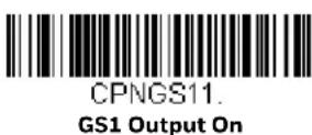
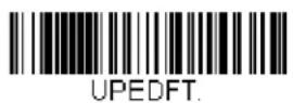
UPC-E0 On/Off
Most U.P.C. bar codes lead with the 0 number system. To read these codes, use the UPC-E0 On selection. If you need to read codes that lead with the 1 number system, use UPC-E1 (page 203). Default = On.

UPEEN01
* UPC-E0 On

UPEENOO
UPC-E0 Off
UPC-EO Expand
UPC-E Expand expands the UPC-E code to the 12 digit, UPC-A format. Default = Off.

UPEEXP1
On

UPEEXPO
* Off
UPC-EO Addenda Required
When Required is scanned, the scanner will only read UPC-E bar codes that have addenda. Default = Not Required.

UPEARQ1
Required

UPEARQO
* Not Required
Addenda Timeout
You can set a time during which the scanner looks for an addenda. If an addenda is not found within this time period, the data can be either transmitted or discarded, based on the setting you are using for UPC-EO Addenda Required. Set the length (in milliseconds) for this timeout by scanning the bar code below, then setting the timeout (from 0-120 milliseconds) by scanning digits from the Programming Chart, beginning on page 341 of this manual, then Save. Default = 500.
Note: The Addenda Timeout setting is applied to all addenda and coupon code searches.
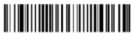
DLYADD.
Addenda Timeout
UPC-E0 Addenda Separator
When this feature is On, there is a space between the data from the bar code and the data from the addenda. When turned Off, there is no space. Default = On.
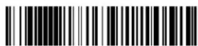
UPEADS1
* On
UPEADSD.
Off
UPC-EO Check Digit
Check Digit specifies whether the check digit should be transmitted at the end of the scanned data or not. Default = On.

UPECKX1
* On
UPECKXD
Off
UPC-EO Leading Zero
This feature allows the transmission of a leading zero (0) at the beginning of scanned data. To prevent transmission, scan Off. Default = On.

UPENSX1.
* On
UPENSX0.
Off
UPC-EO Addenda
This selection adds 2 or 5 digits to the end of all scanned UPC-E data. Default = Off for both 2 Digit and 5 Digit Addenda.

UPEAD21
2 Digit Addenda On
UPEAD20
* 2 Digit Addenda Off

UPEAD51.
5 Digit Addenda On
UPEAD50
* 5 Digit Addenda Off
UPC-E1
Most U.P.C. bar codes lead with the 0 number system. For these codes, use UPC-E0 (page 201). If you need to read codes that lead with the 1 number system, use the UPC-E1 On selection. Default = Off.

UPEEN11
UPC-E1 On

UPEEN10
* UPC-E1 Off
EAN/JAN-13

E13DFT.
EAN/JAN-13 On/Off
E13ENA1.
* On

E13ENAD.
Off
Convert UPC-A to EAN-13
When UPC-A Converted to EAN-13 is selected, UPC-A bar codes are converted to 13 digit EAN-13 codes by adding a zero to the front. When Do not Convert UPC-A is selected, UPC-A codes are read as UPC-A.

UPAENAD
UPC-A Converted to EAN-13

UPAENA1
* Do not Convert UPC-A
EAN/JAN-13 Check Digit
This selection allows you to specify whether the check digit should be transmitted at the end of the scanned data or not. Default = On.

E13CKX1.
* On
E13CKX0.
Off
EAN/JAN-13 Addenda
This selection adds 2 or 5 digits to the end of all scanned EAN/JAN-13 data. Default = Off for both 2 Digit and 5 Digit Addenda.

E13AD21.
2 Digit Addenda On

E13AD20
* 2 Digit Addenda Off

E13AD51
5 Digit Addenda On

E13AD50
* 5 Digit Addenda Off
EAN/JAN-13 Addenda Required
When Required is scanned, the scanner will only read EAN/JAN-13 bar codes that have addenda. Default = Not Required.

E13ARQ1
Required

E13ARQ0
* Not Required
Addenda Timeout
You can set a time during which the scanner looks for an addenda. If an addenda is not found within this time period, the data can be either transmitted or discarded, based on the setting you are using for UPC-EO Addenda Required. Set the length (in milliseconds) for this timeout by scanning the bar code below, then setting the timeout (from 0-120 milliseconds) by scanning digits from the Programming Chart, beginning on page 341 of this manual, then Save. Default = 500.
Note: The Addenda Timeout setting is applied to all addenda and coupon code searches.

DLYADD.
Addenda Timeout
EAN/JAN-13 Addenda Separator
When this feature is On, there is a space between the data from the bar code and the data from the addenda. When turned Off, there is no space. Default = On.

E13ADS1
* On
E13ADSO.
Off
Note: If you want to enable or disable EAN13 with Extended Coupon Code, refer to UPC-A/EAN-13 with Extended Coupon Code (page 199).
ISBN Translate
When On is scanned, EAN-13 Bookland symbols are translated into their equivalent ISBN number format. Default = Off.
E13ISB1.
On
E13ISBO
* Off
EAN/JAN-8

EAN/JAN-8 On/Off


EAN/JAN-8 Check Digit
This selection allows you to specify whether the check digit should be transmitted at the end of the scanned data or not. Default = On.


EAN/JAN-8 Addenda
This selection adds 2 or 5 digits to the end of all scanned EAN/JAN-8 data. Default = Off for both 2 Digit and 5 Digit Addenda.
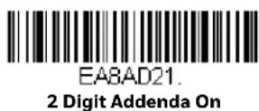
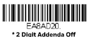

EABAD51
5 Digit Addenda On

EA8AD50
* 5 Digit Addenda Off
EAN/JAN-8 Addenda Required
When Required is scanned, the scanner will only read EAN/JAN-8 bar codes that have addenda. Default = Not Required.

EABARQ1
Required

EASARQO
* Not Required
Addenda Timeout
You can set a time during which the scanner looks for an addenda. If an addenda is not found within this time period, the data can be either transmitted or discarded, based on the setting you are using for UPC-EO Addenda Required. Set the length (in milliseconds) for this timeout by scanning the bar code below, then setting the timeout (from 0-120 milliseconds) by scanning digits from the Programming Chart, beginning on page 341 of this manual, then Save. Default = 500.
Note: The Addenda Timeout setting is applied to all addenda and coupon code searches.

DLYADD.
Addenda Timeout
EAN/JAN-8 Addenda Separator
When this feature is On, there is a space between the data from the bar code and the data from the addenda. When turned Off, there is no space. Default = On.
EA8ADS1
* On
EABADSO.
Off
MSI
MSIDFT.
MSI On/Off
MSIENA1.
On

MSIENAD.
* Off
MSI Check Character
Different types of check characters are used with MSI bar codes. You can program the scanner to read MSI bar codes with Type 10 check characters.
Default = Validate Type 10, but Don't Transmit.
When Check Character is set to Validate Type 10/11 and Transmit, the scanner will only read MSI bar codes printed with the specified type check character(s), and will transmit the character(s) at the end of the scanned data.
When Check Character is set to Validate Type 10/11, but Don't Transmit, the unit will only read MSI bar codes printed with the specified type check character(s), but will not transmit the check character(s) with the scanned data.
MSICHKO.
* Validate Type 10, but Don't
Transmit

MSICHK1
Validate Type 10 and Transmit

MSICHK2
Validate 2 Type 10 Characters, but Don't Transmit

MSICHK3
Validate 2 Type 10 Characters and Transmit
MSICHK4
Validate Type 11 then Type 10
Character, but Don't Transmit

MSICHK5
Validate Type 11 then
Type 10 Character and Transmit

MSICHK6.
Disable MSI Check Characters
MSI Message Length
Scan the bar codes below to change the message length. Refer to Message Length Description (page 178) for additional information. Minimum and Maximum lengths = 4-48. Minimum Default = 4, Maximum Default = 48.

MSIMIN
Minimum Message Length
MSIMAX
Maximum Message Length
GS1 DataBar Omnidirectional
< Default All GS1 DataBar Omnidirectional Settings >

GS1 DataBar Omnidirectional On/Off
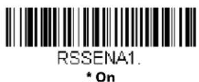

GS1 DataBar Limited
< Default All GS1 DataBar Limited Settings >
GS1 DataBar Limited On/Off

GS1 DataBar Expanded
< Default All GS1 DataBar Expanded Settings >

RSEDFT.
GS1 DataBar Expanded On/Off
RSEENA1
* On
RSEENAD.
Off
GS1 DataBar Expanded Message Length
Scan the bar codes below to change the message length. Refer to Message Length Description (page 178) for additional information. Minimum and Maximum lengths = 4-74. Minimum Default = 4, Maximum Default = 74.

RSEMIN
Minimum Message Length

RSEMAX
Maximum Message Length
Trioptic Code
Note: If you are going to scan Code 32 Pharmaceutical codes (page 183), Trioptic Code must be off.
Trioptic Code is used for labeling magnetic storage media.

TRIENA1
On
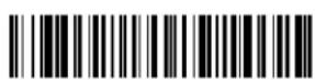
TRIENAD.
* Off
212 Xenon/Granit User Guide
Codablock A

Codablock A On/Off


If you are reading Code 39 bar codes, Codablock A should remain disabled. If you are enabling Codablock A, you should disable Code 39 (see Code 39 on page 181).
Codablock A Message Length
Scan the bar codes below to change the message length. Refer to Message Length Description (page 178) for additional information. Minimum and Maximum lengths = 1-600. Minimum Default = 1, Maximum Default = 600.


Codablock F

CBFDFT.
Codablock F On/Off
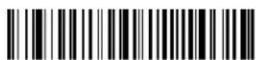
CBFENA1
On

CBFENAD.
* Off
If you are reading Code 128 bar codes, Codablock F should remain disabled. If you are enabling Codablock F, you should disable Code 128 (see Code 128 on page 193).
Codablock F Message Length
Scan the bar codes below to change the message length. Refer to Message Length Description (page 178) for additional information. Minimum and Maximum lengths = 1-2048. Minimum Default = 1, Maximum Default = 2048.

CBFMIN.
Minimum Message Length
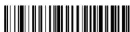
CBFMAX
Maximum Message Length
Label Code
The standard Label Code is used in libraries. Default = Off.

LBLENA1
On

PDF417
< Default All PDF417 Settings >
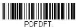
PDF417 On/Off


PDF417 Message Length
Scan the bar codes below to change the message length. Refer to Message Length Description (page 178) for additional information. Minimum and Maximum lengths = 1-2750. Minimum Default = 1, Maximum Default = 2750.

MacroPDF417
MacroPDF417 is an implementation of PDF417 capable of encoding very large amounts of data into multiple PDF417 bar codes. When this selection is enabled, these multiple bar codes are assembled into a single data string. Default = On.

MicroPDF417
< Default All MicroPDF417 Settings >

MicroPDF417 On/Off

MicroPDF417 Message Length
Scan the bar codes below to change the message length. Refer to Message Length Description (page 178) for additional information. Minimum and Maximum lengths = 1-366. Minimum Default = 1, Maximum Default = 366.
GS1 Composite Codes
Linear codes are combined with a unique 2D composite component to form a new class called GS1 Composite symbology. GS1 Composite symbologies allow for the co-existence of symbologies already in use. Default = Off.
COMENA1.
On
COMENAD.
* Off
UPC/EAN Version
Scan the UPC/EAN Version On bar code to decode GS1 Composite symbols that have a U.P.C. or an EAN linear component. (This does not affect GS1 Composite symbols with a GS1-128 or GS1 linear component.) Default = UPC/EAN Version Off.

COMUPC1
UPC/EAN Version On
COMUPCO.
* UPC/EAN Version Off
Note: If you scan coupons that have both UPC and GS1 DataBar codes, you may wish to scan and output only the data from the GS1 DataBar code. See Coupon GS1 DataBar Output (page 200) for further information.
GS1 Composite Code Message Length
Scan the bar codes below to change the message length. Refer to Message Length Description (page 178) for additional information. Minimum and Maximum lengths = 1-2435. Minimum Default = 1, Maximum Default = 2435.

COMMIN.
Minimum Message Length
GS1 Emulation
The scanner can automatically format the output from any GS1 data carrier to emulate what would be encoded in an equivalent GS1-128 or GS1 DataBar symbol. GS1 data carriers include UPC-A and UPC-E, EAN-13 and EAN-8, ITF-14, GS1-128, and GS1-128 DataBar and GS1 Composites. (Any application that accepts GS1 data can be simplified since it only needs to recognize one data carrier type.)
If GS1-128 Emulation is scanned, all retail codes (U.P.C., UPC-E, EAN8, EAN13) are expanded out to 16 digits. If the AIM ID is enabled, the value will be the GS1-128 AIM ID, ]C1 (see Symbology Charts on page 327).
If GS1 DataBar Emulation is scanned, all retail codes (U.P.C., UPC-E, EAN8, EAN13) are expanded out to 16 digits. If the AIM ID is enabled, the value will be the GS1-DataBar AIM ID, ]em (see Symbology Charts on page 327).
If GS1 Code Expansion Off is scanned, retail code expansion is disabled, and UPC-E expansion is controlled by the UPC-E0 Expand (page 201) setting. If the AIM ID is enabled, the value will be the GS1-128 AIM ID, ]C1 (see Symbology Charts on page 327).
If EAN8 to EAN13 Conversion is scanned, all EAN8 bar codes are converted to EAN13 format.
Default = GS1 Emulation Off.

EANEMU1
GS1-128 Emulation

EANEMU2
GS1 DataBar Emulation
EANEMU3
GS1 Code Expansion Off

EANEMU4
EAN8 to EAN13 Conversion

EANEMUO
* GS1 Emulation Off
TCIF Linked Code 39 (TLC39)
This code is a composite code since it has a Code 39 linear component and a MicroPDF417 stacked code component. All bar code readers are capable of reading the Code 39 linear component. The MicroPDF417 component can only be decoded if TLC39 On is selected. The linear component may be decoded as Code 39 even if TLC39 is off. Default = Off.


QR Code
< Default All QR Code Settings >

QR Code On/Off
This selection applies to both QR Code and Micro QR Code.

QR Code Message Length
Scan the bar codes below to change the message length. Refer to Message Length Description (page 178) for additional information. Minimum and Maximum lengths = 1-7089. Minimum Default = 1, Maximum Default = 7089.
QR Code Append
This function allows the scanner to append the data from several QR Code bar codes together before transmitting them to the host computer. When the scanner encounters an QR Code bar code with the append trigger character(s), it buffers the number of QR Code bar codes determined by information encoded in those bar codes. Once the proper number of codes is reached, the data is output in the order specified in the bar codes. Default = On.
QRCAPP1
* On

QRCAPPO.
Off
QR Code Page
QR Code pages define the mapping of character codes to characters. If the data received does not display with the proper characters, it may be because the bar code being scanned was created using a code page that is different from the one the host program is expecting. If this is the case, scan the bar code below, select the code page with which the bar codes were created (see ISO 2022/ISO 646 Character Replacements on page 334), and scan the value and the Save bar code from the Programming Chart, beginning on page 341 Programming Chart, beginning on page 341. The data characters should then appear properly.

QRCDCP.
QR Code Page
Data Matrix
< Default All Data Matrix Settings >
Data Matrix On/Off


Data Matrix Message Length
Scan the bar codes below to change the message length. Refer to Message Length Description (page 178) for additional information. Minimum and Maximum lengths = 1-3116. Minimum Default = 1, Maximum Default = 3116.


Data Matrix Append
This function allows the scanner to append the data from several Data Matrix bar codes together before transmitting them to the host computer. When the scanner encounters an Data Matrix bar code with the append trigger character(s), it buffers the number of Data Matrix bar codes determined by information encoded in those bar codes. Once the proper number of codes is reached, the data is output in the order specified in the bar codes. Default = On.

Data Matrix Code Page
Data Matrix Code pages define the mapping of character codes to characters. If the data received does not display with the proper characters, it may be because the bar code being scanned was created using a code page that is different from the one the host program is expecting. If this is the case, scan the bar code below, select the code page with which the bar codes were created (see ISO 2022/ISO 646 Character Replacements on page 334), and scan the value and the Save bar code from the Programming Chart, beginning on page 341. The data characters should then appear properly.
IDMDCP.
Data Matrix Code Page
MaxiCode
< Default All MaxiCode Settings >

MAXDFT.
MaxiCode On/Off

MAXENA1
On
MAXENAD.
* Off
MaxiCode Message Length
Scan the bar codes below to change the message length. Refer to Message Length Description (page 178) for additional information. Minimum and Maximum lengths = 1-150. Minimum Default = 1, Maximum Default = 150.
MAXMIN
Minimum Message Length

MAXMAX
Maximum Message Length
Aztec Code
< Default All Aztec Code Settings >

AZTDFT.
Aztec Code On/Off

AZTENA1
* On

AZTENAD.
Off
Aztec Code Message Length
Scan the bar codes below to change the message length. Refer to Message Length Description (page 178) for additional information. Minimum and Maximum lengths = 1-3832. Minimum Default = 1, Maximum Default = 3832.
AZTMIN
Minimum Message Length

AZTMAX
Maximum Message Length
Aztec Append
This function allows the scanner to append the data from several Aztec bar codes together before transmitting them to the host computer. When the scanner encounters an Aztec bar code with the append trigger character(s), it buffers the number of Aztec bar codes determined by information encoded in those bar codes. Once the proper number of codes is reached, the data is output in the order specified in the bar codes. Default = On.

AZTAPP1
* On

AZTAPPO.
Off
Aztec Code Page
Aztec Code pages define the mapping of character codes to characters. If the data received does not display with the proper characters, it may be because the bar code being scanned was created using a code page that is different from the one the host program is expecting. If this is the case, scan the bar code below, select the code page with which the bar codes were created (see ISO 2022/ISO 646 Character Replacements on page 334), and scan the value and the Save bar code from the Programming Chart, beginning on page 341. The data characters should then appear properly.
AZTDCP.
Aztec Code Page
Chinese Sensible (Han Xin) Code
< Default All Han Xin Settings >

HX_DFT.
Han Xin Code On/Off

HX_ENA1
On
224 Xenon/Granit User Guide

Han Xin Code Message Length
Scan the bar codes below to change the message length. Refer to Message Length Description (page 178) for additional information. Minimum and Maximum lengths = 1-7833. Minimum Default = 1, Maximum Default = 7833.

Postal Codes - 2D
The following lists the possible 2D postal codes, and 2D postal code combinations that are allowed. Only one 2D postal code selection can be active at a time. If you scan a second 2D postal code selection, the first selection is overwritten. Default = 2D Postal Codes Off.

Single 2D Postal Codes:



POSTAL3
Japanese Post On

POSTAL10
Intelligent Mail Bar Code On

POSTALS
Planet Code On
Also see Planet Code Check
Digit, page 229.
POSTAL4
KIX Post On
POSTAL6
Postnet On
Also see Postnet Check
Digit, page 229.

POSTAL9
Postal-4i On

POSTAL2
InfoMail On

POSTAL11
Postnet with B and B' Fields On
Combination 2D Postal Codes:
POSTAL8
InfoMail and British
Post On

POSTAL14
Postnet and Postal-4i On
POSTAL20
Intelligent Mail Bar Code and Postnet with B and B' Fields On

POSTAL17.
Postal-4i and
Intelligent Mail Bar Code On

POSTAL16. Postnet and Intelligent Mail Bar Code On
POSTAL12.
Planet Code and
Postnet On
POSTAL19.
Postal-4i and
Postnet with B and B' Fields On

POSTAL13.
Planet Code and
Postal-4i On

POSTAL18. Planet Code and Postnet with B and B' Fields On

POSTAL21

POSTAL15. Planet Code and Intelligent Mail Bar Code
Planet Code, Postnet, and Postal-4i On
POSTAL23
Planet Code,
Postal-4i, and
Intelligent Mail Bar Code On

POSTAL25
Planet Code,
Postal-4i, and
Postnet with B and B' Fields On

POSTAL27
Postal-4i,
Intelligent Mail Bar Code, and
Postnet with B and B' Fields On
POSTAL29
Planet Code,
Postal-4i.
Intelligent Mail Bar Code, and
Postnet with B and B' Fields On

POSTAL22
Planet Code,
Postnet, and
Intelligent Mail Bar Code On

POSTAL24
Postnet,
Postal-4i, and
Intelligent Mail Bar Code On

POSTAL26
Planet Code,
Intelligent Mail Bar Code, and Postnet with B and B' Fields Or

POSTAL28
Planet Code,
Postal-4i,
Intelligent Mail Bar Code, and
Postnet On
Planet Code Check Digit
This selection allows you to specify whether the check digit should be transmitted at the end of Planet Code data. Default = Don't Transmit.

PLNCKX1
Transmit Check Digit

PLNCKXD.
* Don't Transmit Check Digit
Postnet Check Digit
This selection allows you to specify whether the check digit should be transmitted at the end of Postnet data. Default = Don't Transmit.

NETCKX1
Transmit Check Digit

NETCKXD
* Don't Transmit Check Digit
Australian Post Interpretation
This option controls what interpretation is applied to customer fields in Australian 4-State symbols.
Bar Output lists the bar patterns in "0123" format.
Numeric N Table causes that field to be interpreted as numeric data using the N Table.
Alphanumeric C Table causes the field to be interpreted as alphanumeric data using the C Table. Refer to the Australian Post Specification Tables.
Combination C and N Tables causes the field to be interpreted using either the C or N Tables.

AUSINTO
* Bar Output

AUSINT2
Alphanumeric C Table

AUSINT1
Numeric N Table
AUSINT3
Combination C and N Tables
Postal Codes - Linear
The following lists linear postal codes. Any combination of linear postal code selections can be active at a time.
China Post (Hong Kong 2 of 5)

CPCDFT.
China Post (Hong Kong 2 of 5) On/Off
CPCENA1
On

CPCENAD.
* Off
China Post (Hong Kong 2 of 5) Message Length
Scan the bar codes below to change the message length. Refer to Message Length Description (page 178) for additional information. Minimum and Maximum lengths = 2-80. Minimum Default = 4, Maximum Default = 80.

CPCMIN.
Minimum Message Length

CPCMAX
Maximum Message Length
Korea Post

KPCDFT
Korea Post

KPCENA1.
On

KPCENAD.
* Off
Korea Post Message Length
Scan the bar codes below to change the message length. Refer to Message Length Description (page 178) for additional information. Minimum and Maximum lengths = 2-80. Minimum Default = 4, Maximum Default = 48.

KPCMIN
Minimum Message Length

KPCMAX.
Maximum Message Length
Korea Post Check Digit
This selection allows you to specify whether the check digit should be transmitted or not. Default = Don't Transmit.

KPCCHK1.
Transmit Check Digit
The scanner is like a digital camera in the way it captures, manipulates, and transfers images. The following commands allow you to alter the way the scanner performs these functions.
Note: If you are using the scanner in a stand, you must set the In-Stand Sensor Mode to Off in order to take images (see In-Stand Sensor Mode on page 122).
Single-Use Basis
Imaging Commands with their modifiers send instructions to the scanner on a single-use basis, and take effect for a single image capture. Once that capture is complete, the scanner reverts to its imaging default settings. If you want to permanently change a setting, you must use the serial default commands (see Chapter 12). When the serial default command is used, that selection becomes the new, permanent setting for the scanner.
Command Syntax
Multiple modifiers and commands can be issued within one sequence. If additional modifiers are to be applied to the same command, just add the modifiers to that command. For example, to add 2 modifiers to the Image Snap command, such as setting the Imaging Style to 1P and the Wait for Trigger to 1T, you would enter IMGSNP1P1T.
Note: After processing an image capture command (IMGSNP or IMGBOX), you must follow it with an IMGSHP command if you want to see it on your terminal.
To add a command to a sequence, each new command is separated with a semicolon. For example, to add the Image Ship command to the above sequence, you would enter IMGSNP1P1T;IMGSHP.
The imaging commands are:
Image Snap - IMGSNP (page 234)
Image Ship - IMGSHP (page 237)
Intelligent Signature Capture - IMGBOX (page 247)
The modifiers for each of these commands follow the command description.
Note: The images included with each command description are examples only. The results you achieve may be different from those included in this manual. The quality of the output you receive will vary depending on lighting, quality of the initial image/object being captured, and distance of the scanner from the image/object. To achieve a high quality image, it is recommended that you position your scanner 4-6" (10.2-15.2 cm) away from the image/object you are capturing.
Step 1 - Take a Picture Using IMGSNP
Image Snap - IMGSNP
An image is taken whenever the hardware trigger is pressed, or when the Image Snap (IMGSNP) command is processed.
The image snap command has many different modifiers that can be used to change the look of the image in memory. Any number of modifiers may be appended to the IMGSNP command.
Example: You can use the following command to snap an image, increase the gain, and have the beeper sound once the snap is complete: IMGSNP2G1B
IMGSNP Modifiers
P - Imaging Style
This sets the Image Snap style.
OP Decoding Style. This processing allows a few frames to be taken until the exposure parameters are met. The last frame is then available for further use.
1P Photo Style (default). This mimics a simple digital camera, and results in a visually optimized image.
2P Manual Style. This is an advanced style that should only be used by an experienced user. It allows you the most freedom to set up the scanner, and has no auto-exposure.
B - Beeper
Causes a beep to sound after an image is snapped.
OB No beep (default)
1B Sounds a beep when the image is captured.
T - Wait for Trigger
Waits for a hardware trigger press before taking the image. This is only available when using Photo Style (1P).
OT Takes image immediately (default)
1T Waits for a trigger press, then takes the image
L - LED State
Determines if the LEDs should be on or off, and when. Ambient illumination (OL) is preferred for taking pictures of color documents, such as ID cards, especially when the scanner is in a stand. LED illumination (1L) is preferred when the scanner is handheld. LED State is not available when using Decoding Style (OP).
OL LEDs off (default)
1L LEDs on
E - Exposure
Exposure is used in Manual Style only (2P), and allows you to set the exposure time. This is similar to setting a shutter speed on a camera. The exposure time determines how long the scanner takes to record an image. On a bright day, exposure times can be very short because plenty of light is available to help record an image. At nighttime, exposure time can increase dramatically due to the near absence of light. Units are 127 microseconds. (Default = 7874)
nE Range: 1 - 7874
Example:
Exposure at 7874E with fluorescent lighting:
natural_image
Illustration of a human face with floating digital screens and charts, symbolizing data or system integration (no text or symbols present)
Exposure at 100E with fluorescent lighting:

natural_image
Silhouette of a person's face with abstract digital interface elements overlaying (no text or symbols)
G - Gain
Gain is used in Manual Style only (2P). Like a volume control, the gain modifier boosts the signal and multiplies the pixel value. As you increase the gain, the noise in an image is also amplified.
1G No gain (default)
2G Medium gain
4G Heavy gain
8G Maximum gain
Example: Gain at 1G: Gain at 4G: Gain at 8G:


W - Target White Value
Sets the target for the median grayscale value in the captured image. For capturing close-up images of high contrast documents, a lower setting, such as 75, is recommended. Higher settings result in longer exposure times and brighter images, but if the setting is too high, the image may be overexposed. Target White Value is only available when using Photo Style (1P). (Default = 125)
nW Range: 0 - 255
Example: White Value at 75W: White Value at 125W: White Value at 200W:

D - Delta for Acceptance
This sets the allowable range for the white value setting (see W - Target White Value). Delta is only available when using Photo Style (1P). (Default = 25)
nD Range: 0 - 255
U - Update Tries
This sets the maximum number of frames the scanner should take to reach the D-Delta for Acceptance. Update Tries is only available when using Photo Style (1P). (Default = 6)
nU R a n g e : 0 - 1 0
% - Target Set Point Percentage
Sets the target point for the light and dark values in the captured image. A setting of 75% means 75% of the pixels are at or below the target white value, and 25% of the pixels are above the target white value. Altering this setting from the default is not recommended under normal circumstances. To alter grayscale values, W - Target White Value should be used. (Default = 50)
n% Range: 1 - 99
Example:
Target Set Point Percentage at 97%:
Target Set Point Percentage at 50%:
Target Set Point Percentage at 40%:


Lorem ipsum dolor sit amet, consectetur adipiscing elit. Curabitur massa. Lorem ipsum dolor sit amet, consectetur adipiscing elit. Donec interdum volutpat arcu. Pruin sed turpis. Donec
Step 2 - Ship a Picture Using IMGSHP
Image Ship - IMGSHP
An image is taken whenever the trigger is pressed or when the Image Snap (IMGSNP) command is processed. The last image is always stored in memory. You can “ship” the image by using the IMGSHP command.
The image ship commands have many different modifiers that can be used to change the look of the image output. Modifiers affect the image that is transmitted, but do not affect the image in memory. Any number of modifiers may be appended to the IMGSHP command.
Example: You can use the following command to snap and ship a bitmap image with gamma correction and document image filtering: IMGSNP;IMGSHP8F75K26U
IMGSHP Modifiers
A - Infinity Filter
Enhances pictures taken from very long distances (greater than 10 feet or 3m). The Infinity Filter should not be used with IMGSNP Modifiers (page 234).
OA Infinity filter off (default)
1A Infinity filter on
Example:
Infinity Filter off (OA) from approximately 12 feet (3.66m) away:
infinity Filter on (1A)
from approximately 12 feet (3.66m)
away:

natural_image
Simple black-and-white line drawing of a curved path inside a rectangular frame (no text or symbols)

natural_image
Simple line drawing of a rising trend inside a square frame (no text or symbols)
C - Compensation
Flattens the image to account for variations in illumination across the image.
OC Compensation disabled (default)
1C Compensation enabled
Example:
Compensation at OC: Compensation at 1C:
natural_image
Symmetrical ornamental design with swirling floral patterns on a textured dark background (no text or symbols)

natural_image
Ornamental symmetrical floral or scroll design on a textured dark background (no text or symbols)
D - Pixel Depth
Indicates the number of bits per pixel in the transmitted image (KIM or BMP format only).
8D 8 bits per pixel, grayscale image (default)
1D 1 bit per pixel, black and white image
238 Xenon/Granit User Guide
E - Edge Sharpen
An edge sharpen filter cleans up the edges of an image, making it look cleaner and sharper. While edge sharpening does make the image look cleaner, it also removes some fine detail from the original image. The strength of the edge sharpen filter can be entered from 1 to 24. Entering a 23E gives the sharpest edges, but also increases noise in the image.
OE Don't sharpen image (default)
14E Apply edge sharpen for typical image
ne Apply edge sharpen using strength n (n = 1-24)
Example:
natural_image
Abstract black-and-white sketch of intersecting lines and shapes (no text or symbols)

natural_image
Abstract geometric sculpture made of intersecting rods or rods, no text or symbols present
Indicates the desired format for the image.
OF KIM format
1F TIFF binary
2F TIFF binary group 4, compressed
3F TIFF grayscale
4F Uncompressed binary (upper left to lower right, 1 pixel/bit, 0 padded end of line)
5F Uncompressed grayscale (upper left to lower right, bitmap format)
6F JPEG image (default)
8F BMP format (lower right to upper left, uncompressed)
10F TIFF color compressed image
11F TIFF color uncompressed image
12F JPEG color image
14F BMP color format
15F BMP Uncompressed raw image
H - Histogram Stretch
Increases the contrast of the transmitted image. Not available with some image formats.
OH No stretch (default)
1H Histogram stretch
Example: Histogram Stretch at 0H: Histogram Stretch at 1H:

natural_image
Close-up of a metallic bead bracelet with evenly spaced beads (no text or symbols visible)
natural_image
Close-up of a metallic bead bracelet with a curved chain (no text or symbols visible)
I - Invert Image
Invert image is used to rotate the image around the X or Y axis.
1ix Invert around the X axis (flips picture upside down)
1iy Invert around the Y axis (flips picture left to right)
Example:
Image not inverted: Image with the invert
Image set to 1ix:

natural_image
Black-and-white photograph of the Statue of Liberty, featuring its iconic column and flared base (no visible text or symbols)

natural_image
Black-and-white photo of a tall, twisted column structure resembling the Statue of Liberty, with no visible text or symbols.
Image set to 1iy:

natural_image
Black-and-white photograph of the Statue of Liberty, featuring its iconic column and spiky facade (no visible text or symbols)
IF- Noise Reduction
Used to reduce the salt and pepper noise in an image.
Oif No salt and pepper noise reduction (default)
1if Salt and pepper noise reduction
Example:
natural_image
Black-and-white photo of four playing cards (J, Q, K) with visible hearts and a cartoon character on the right side (no text or symbols)
Noise Reduction On (1if): Noise Red

natural_image
Close-up of three playing cards (J, Q, K) with visible suits and a central figure (no text or symbols beyond card markings)
IR - Image Rotate
Oir Image as snapped (rightside up) (default)
1ir Rotate image 90 degrees to the right
2ir Rotate image 180 degrees (upside down)
3ir Rotate image 90 degrees to the left
Example:
Image Rotate set to Oir:
Image Rotate set to 2ir:

Image Rotate set to 1ir: Image Rotate set to 3ir:
natural_image
Close-up of two metal pliers with textured handles and mounting holes (no visible text or symbols)

J - JPEG Image Quality
Sets the desired quality when the JPEG image format is selected. Higher numbers result in higher quality, but larger files. Smaller numbers result in greater amounts of lossy compression, faster transmission times, lower quality, but smaller files. (Default = 50)
nJ Image is compressed as much as possible while preserving quality factor of n (n = 0 - 100)
OJ worst quality (smallest file)
100J best quality (largest file)
K - Gamma Correction
Gamma measures the brightness of midtone values produced by the image. You can brighten or darken an image using gamma correction. A higher gamma correction yields an overall brighter image. The lower the setting, the darker the image. The optimal setting for text images is 50K.
OK Gamma correction off (default)
50K Apply gamma correction for brightening typical document image
nK Apply gamma correction factor n (n = 0-1,000)
Example:
Gamma Correction set to OK:

Gamma Correction set to 50K:

Gamma Correction set to 255K:

L, R, T, B, M - Image Cropping
Ships a window of the image by specifying the left, right, top, and bottom pixel coordinates. Device columns are numbered 0 through 1279, and device rows are numbered 0 through 959.
nL The left edge of the shipped image corresponds to column n of the image in memory. Range: 000 - 843. (Default = 0)
nR The right edge of the shipped image corresponds to column n - 1 of the image in memory. Range: 000 - 843. (Default = all columns)
nT The top edge of the shipped image corresponds to row n of the image in memory. Range: 000 - 639. (Default = 0)
nB The bottom edge of the shipped image corresponds to row n - 1 of the image in memory. Range: 000 - 639. (Default = all rows)
Example:
Uncropped Image:
natural_image
Close-up of a vintage pocket watch with visible internal patterns and Roman numerals (no text or symbols)
Image Crop set to 300R:

Image Crop set to 300L:
Image Crop set to 200T:Image Crop set

Alternately, specify the number of pixels to cut from the outside margin of the image; thus only the center pixels are transmitted.
nM Margin: cut n columns from the left, n + 1 columns from the right, n rows from the top, and n + 1 rows from the bottom of the image. Ship the remaining center pixels. Range: 0 - 238.
(Default = 0, or full image)
Example:
Image Crop set to 238M:

P - Protocol
Used for shipping an image. Protocol covers two features of the image data being sent to the host. It addresses the protocol used to send the data (Hmodem, which is an Xmodem 1K variant that has additional header information), and the format of the image data that is sent.
OP None (raw data)
2P None (default for USB)
3P Hmodem compressed (default for RS232)
4P Hmodem
S - Pixel Ship
Pixel Ship sizes an image in proportion to its original size. It decimates the image by shipping only certain, regularly spaced pixels.
Example: 4S would transmit every fourth pixel from every fourth line.
244 Xenon/Granit User Guide
The smaller number of pixels shipped, the smaller the image, however, after a certain point the image becomes unusable.
1S ship every pixel (default)
2S ship every 2nd pixel, both horizontally and vertically
3S ship every 3rd pixel, both horizontally and vertically
Example:
Pixel Ship set to 1S:

Pixel Ship set to 2S:

Pixel Ship set to 3S:

Pixel Ship set to 4S:

U - Document Image Filter
Allows you to input parameters to sharpen the edges and smooth the area between the edges of text in an image. This filter should be used with gamma correction (see page 243), with the scanner in a stand, and the image captured using the command:
IMGSNP1P0L168W90%32D
This filter typically provides better JPEG compression than the standard E - Edge Sharpen command (see page 246). This filter also works well when shipping pure black and white images (1 bit per pixel). The optimal setting is 26U.
OU Document image filter off (default)
26U Apply document image filter for typical document image
nU Apply document image filter using grayscale threshold n. Use lower numbers when the image contrast is lower. 1U will have a similar effect to setting E - Edge Sharpen (page 239) to 22e. Range: 0-255.
Example:
Document Image Filter set to 0U: Document Image Filter set to 26U:

V - Blur Image
Smooths transitions by averaging the pixels next to the hard edges of defined lines and shaded areas in an image.
OV Don't blur (default)
1V Blur
Example: Blur Image Off (0V): Blur Image On (1V):


W - Histogram Ship
A histogram gives a quick picture of the tonal range of an image, or key type. A low-key image has detail concentrated in the shadows; a high-key image has detail concentrated in the highlights; and an average-key image has detail concentrated in the midtones. This modifier ships the histogram for an image.
OW Don't ship histogram (default)
1W Ship histogram
Example: Image used for histogram: Histogram of image:

natural_image
Close-up of multiple screws with metallic and threaded surfaces (no visible text or markings)

natural_image
Completely blank white image with no visible content, text, or symbols.
Image Size Compatibility
If you have applications that expect an image ship to return exactly 640x480 pixels, scan the Force VGA Resolution bar code. Default = Native Resolution.

IMGVGA1
Force VGA Resolution
Intelligent Signature Capture - IMGBOX
IMGBOX allows you to configure the size and location of a signature capture area relative to its proximity to a bar code. This allows you to tailor a signature capture area to a specific form. In order to use IMGBOX, you need a set form where the signature box location is in a known location relative to a bar code. You can input the overall size of the signature area, as well as specify how far the signature area is from the bar code, vertically and horizontally. You can also set the resolution and file format for the final output of the signature capture image.
Note: IMGBOX commands can only be triggered by one of the following types of bar codes: PDF417, Code 39, Code 128, Aztec, Codabar, and Interleaved 2 of 5. Once one of these symbologies has been read, the image is retained for a possible IMGBOX command.
Signature Capture Optimize
If you will be using your scanner to capture signatures frequently, you should optimize it for this purpose. However, the speed of scanning bar codes may be slowed when this mode is enabled. Default = Off.

DECBND1
Optimize On
DECBNDO.
* Optimize Off
Below is an example of a signature capture application. In this example, the aimer is centered over the signature capture area and the trigger is pressed. A single beep is emitted, indicating that the scanner has read a Code 128 bar code and the data has been transferred to the host. If using a Granit scanner, the scanner also vibrates. An IMGBOX command may now be sent from the host to specify the coordinates of the signature capture area below that code, and indicating that only that area containing the signature should be transferred as an image to the host.
To see this example, align the aimer with the signature area (not with the bar code), then press the trigger.

Signature Capture Area
Send the following IMGBOX command string after the trigger press:
Example: IMGBOX245w37h55y.
Note: Case is not important in the command string. It is used here only for clarity.
The following image is captured:
Signature Capture Area
The IMGBOX commands have many different modifiers that can be used to change the size and appearance of the signature image output by the scanner. Modifiers affect the image that is transmitted, but do not affect the image in memory. Any number of modifiers may be appended to the IMGBOX command.
Note: The IMGBOX command will return a NAK unless a window size (width and height) are specified. See H - Height of Signature Capture Area (page 250) and W - Width of Signature Capture Area (page 251).
IMGBOX Modifiers
A - Output Image Width
This option is used to size the image horizontally. If using this option, set the resolution (R) to zero.
Example: Image Width set to 200A:

Image Width set to 600A:

B - Output Image Height
This option is used to size the image vertically. If using this option, set the resolution (R) to zero.
Example:
Image Height set to 50B:
Signature Capture Area
Image Height set to 100B:
Signature Capture Area
D - Pixel Depth
This indicates the number of bits per pixel in the transmitted image, which defines whether it will be grayscale or black and white.
8D 8 bits per pixel, grayscale image (default)
1D 1 bit per pixel, black and white image
This option indicates the type of file format in which to save the image.
OF KIM format
1F TIFF binary
2F TIFF binary group 4, compressed
3F TIFF grayscale
4F Uncompressed Binary
5F Uncompressed grayscale
6F JPEG image (default)
7F Outlined image
8F BMP format
H - Height of Signature Capture Area
The height of the signature capture area must be measured in inches divided by .01. In the example, the height of the area to be captured is 3/8 inch, resulting in a value of H = .375/0.01 = 37.5.
Example: IMGBOX245w37h55y.
K - Gamma Correction
Gamma measures the brightness of midtone values produced by the image. You can brighten or darken an image using gamma correction. A higher gamma correction yields an overall brighter image. The lower the setting, the darker the image. The optimal setting for text images is 50K.
OK Gamma correction off (default)
50K Apply gamma correction for brightening typical document image
nK Apply gamma correction factor n (n = 1-255)
Example: Gamma Correction set to OK:

Gamma Correction set to 50K:

Gamma Correction set to 255K:

R - Resolution of Signature Capture Area
The resolution is the number of pixels that the scanner outputs per each minimum bar width. The higher the value for R, the higher the quality of the image, but also the larger the file size. Values begin at 1000. The scanner automatically inserts a
decimal point between the first and second digit. For example, use 2500 to specify a resolution of 2.5. Set to zero when using the A and B modifiers (see A - Output Image Width and B - Output Image Height on page 249).
Example:
Resolution set to OR:
Signature Capture Area
Resolution set to 1000R:
Signature Capture Area
Resolution set to 2000R:
Signature Capture Area
S - Bar Code Aspect Ratio
All dimensions used in IMGBOX are measured as multiples of the minimum element size of the bar code. The bar code aspect ratio allows you to set the ratio of the bar code height to the narrow element width. In the example, the narrow element width is .010 inches and the bar code height is 0.400 inches, resulting in a value of S = 0.4/0.01 = 40.
W - Width of Signature Capture Area
The width of the signature capture area must be measured in inches divided by .01. In the example, the width of the area to be captured is 2.4 inches, resulting in a value of W = 2.4/0.01 = 240. (A value of 245 was used in the example to accommodate a slightly wider image area.)
Example: IMGBOX245w37h55y.
X - Horizontal Bar Code Offset
The horizontal bar code offset allows you to offset the horizontal center of the signature capture area. Positive values move the horizontal center to the right and negative values to the left. Measurements are in multiples of the minimum bar width.
Example:
Horizontal Offset set to 75X:
lure Capture Area
Horizontal Offset set to -75X:
Signature Capture
Y - Vertical Bar Code Offset
The vertical bar code offset allows you to offset the vertical center of the signature capture area. Negative numbers indicate that the signature capture is above the bar code, and positive numbers indicate that the area is below the bar code. Measurements are in multiples of the minimum bar width
Example: . Vertical Offset set to -7Y:

Vertical Offset set to 65Y:
Signature Capture Area
RF Default Imaging Device
The scanner supports imaging command processing (IMGSHP, IMGSNP, IMGBOX) so that EZConfig-Scanning (see page 255) and other applications are able to perform imaging functions as if they were communicating directly with a scanner. To accomplish this, the scanner uses a menu command called RF_DID (RF Default Imaging Device). RF_DID is the name of the scanner (BT_NAM) that is to receive imaging commands. The default for RF_DID is “*” indicating that imaging commands are to be sent to all associated scanners. Change this setting to RF_DID-scanner_name to ensure that they are sent to a particular scanner. Refer to "Page" on page 3-51 to generate a report containing the port, work group, scanner name, and address for each scanner. Refer to "Scanner Name" on page 3-65 set a unique name for each scanner.
To Add a Test Code I.D. Prefix to All Symbologies
This selection allows you to turn on transmission of a Code I.D. before the decoded symbology. (See the Symbology Charts, beginning on page 327) for the single character code that identifies each symbology.) This action first clears all current prefixes, then programs a Code I.D. prefix for all symbologies. This is a temporary setting that will be removed when the unit is power cycled.

PRECA2,BK2995C80!
Add Code I.D. Prefix to
All Symbologies (Temporary)
Show Decoder Revision
Scan the bar code below to output the decoder revision.

REV DR
Show Decoder Revision
Show Scan Driver Revision
Scan the bar code below to output the scan driver revision. The scan driver controls image capture.

REV SD
Show Scan Driver Revision
Show Software Revision
Scan the bar code below to output the current software revision, unit serial number, and other product information for both the scanner and base.

REVINF
Show Software Revision
Scan the bar code below to show current data format settings.

DFMBK3?.
Data Format Settings
When you scan the Test Menu On code, then scan a programming code in this manual, the scanner displays the content of a programming code. The programming function will still occur, but in addition, the content of that programming code is output to the terminal.
Note: This feature should not be used during normal scanner operation.

TSTMNU1
On
TSTMNUO
* Off
TotalFreedom
TotalFreedom is an open system architecture that makes it possible for you create applications that reside on your scanner. Decoding apps and Data Formatting apps can be created using TotalFreedom. For further information about TotalFreedom, go to our website at www.honeywellaidc.com.
Application Plug-Ins (Apps)
Any apps that you are using can be turned off or on by scanning the following bar codes. Apps are stored in groups: Decoding, and Formatting. You can enable and disable these groups of apps by scanning that group's On or Off bar code below. You can also scan the List Apps bar code to output a list of all your apps.

PLGDCE1.
* Decoding Apps On

PLGDCEO.
Decoding Apps Off
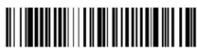
PLGFOE1
* Formatting Apps On
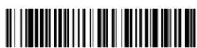
PLGFOEO.
Formatting Apps Off

PLGINF.
List Apps
Note: You must reset your device in order for the apps setting to take effect.
EZConfig Cloud for Scanning Introduction
EZConfig Cloud for Scanning provides a wide range of PC-based programming functions that can be performed on a scanner connected to your PC. EZConfig Cloud for Scanning allows you to download upgrades to the scanner's firmware, change programmed parameters, and create and print programming bar codes. Using EZConfig Cloud for Scanning, you can even save/open the programming parameters for a scanner. This saved file can be e-mailed or, if required, you can create a single bar code that contains all the customized programming parameters and mail or fax that bar code to any location. Users in other locations can scan the bar code to load in the customized programming.
EZConfig Cloud for Scanning Operations
The EZConfig Cloud for Scanning software performs the following operations:
Scan Data
Scan Data allows you to scan bar codes and display the bar code data in a window. Scan Data lets you send serial commands to the scanner and receive scanner response that can be seen in the Scan Data window. The data displayed in the Scan Data window can either be saved in a file or printed.
Configure displays the programming and configuration data of the scanner. The scanner's programming and configuration data is grouped into different categories. Each category is displayed as a tree item under the "Configure" tree node in the application explorer. When one of these tree nodes is clicked, the right-hand side is loaded with the parameters' form belonging to that particular category. The "Configure" tree option has all the programming and configuration parameters specified for a scanner. You can set or modify these parameters as required. You can later write the modified settings to the scanner, or save them to a dcf file.
Imaging
Imaging provides all the image-related functions that a 2D Scanner can perform. You can capture an image using the current settings, and the image will be displayed in an image window. Images captured from the scanner can be saved to files in different image formats. You can modify the image settings and save the image settings to an INI file, which can be loaded later to capture new images. Imaging also lets you preview the images continuously captured by the scanner.
Install EZConfig Cloud for Scanning
Use the EZConfig Cloud for Scanning tool to configure your scanner online:
- Access the Honeywell web site at www.honeywellaidc.com
- Click on the Browse Products tab. Under Software, select Device Management.
- Click on EZConfig Cloud for Scanning.
- Scroll to the bottom of the page and click on Register for free access now to sign up.
Reset the Factory Defaults

Caution: This selection erases all your settings and resets the scanner to the original factory defaults. It also disables all plugins.
If you aren't sure what programming options are in your scanner, or you've changed some options and want to restore the scanner to factory default settings, first scan the Remove Custom Defaults bar code, then scan Activate Defaults. This resets the scanner to the factory default settings.
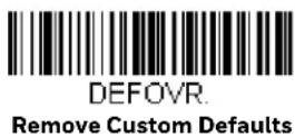

Note: If using a cordless system, scanning the Activate Defaults bar code also causes both the scanner and the base or Access Point to perform a reset and become unlinked. The scanner must be placed in its base to re-establish the link before any setup codes are entered. If using an Access Point, the linking bar code must be scanned. See Cordless System Operation: Xenon 1902g/1912 and Granit 1911i/1981i beginning on page 41, or Cordless System Operation: Xenon 1902g-BF beginning on page 79 for additional information.
The Menu Commands, beginning on page 264, list the factory default settings for each of the commands (indicated by an asterisk (*) on the programming pages).
The serial programming commands can be used in place of the programming bar codes. Both the serial commands and the programming bar codes will program the scanner. For complete descriptions and examples of each serial programming command, refer to the corresponding programming bar code in this manual.
The device must be set to an RS232 interface (see page 16). The following commands can be sent via a PC COM port using terminal emulation software.
Conventions
The following conventions are used for menu and query command descriptions:
parameter A label representing the actual value you should send as part of a command.
[option] An optional part of a command.
{Data} Alternatives in a command.
bold Names of menus, menu commands, buttons, dialog boxes, and windows that appear on the screen.
Menu Command Syntax
Menu commands have the following syntax (spaces have been used for clarity only):
Prefix[:Name:] Tag SubTag {Data} [, SubTag {Data}] [; Tag SubTag {Data}] [...] Storage
Prefix Three ASCII characters: SYN M CR (ASCII 22,77,13).
:Name: This command is only used with cordless devices. It is used to specify whether you're communicating with the base or the scanner. To send information to the scanner (with the base connected to host), use :Xenon: The default factory setting for a Xenon scanner is Xenon
scanner. This setting is changed by using the BT_NAM command, which accepts alphanumeric values. If the name is not known, a wildcard (*) can be used:*
Note: Since the base stores all work group settings and transfers to them to scanner once they are linked, changes are typically done to the base and not to the scanner.
Tag A 3 character case-insensitive field that identifies the desired menu command group. For example, all RS232 configuration settings are identified with a Tag of 232.
SubTag A 3 character case-insensitive field that identifies the desired menu command within the tag group. For example, the SubTag for the RS232 baud rate is BAD.
Data The new value for a menu setting, identified by the Tag and SubTag.
Storage A single character that specifies the storage table to which the command is applied. An exclamation point (!) performs the command's operation on the device's volatile menu configuration table. A period (.) performs the command's operation on the device's non-volatile menu configuration table. Use the non-volatile table only for semi-permanent changes you want saved through a power cycle.
Query Commands
Several special characters can be used to query the device about its settings.
^ What is the default value for the setting(s).
? What is the device's current value for the setting(s).
* What is the range of possible values for the setting(s). (The device's response uses a dash (-) to indicate a continuous range of values. A pipe (l) separates items in a list of non-continuous values.)
:Name: Field Usage (Optional)
This command returns the query information from the scanner.
Tag Field Usage
When a query is used in place of a Tag field, the query applies to the entire set of commands available for the particular storage table indicated by the Storage field of the command. In this case, the SubTag and Data fields should not be used because they are ignored by the device.
SubTag Field Usage
When a query is used in place of a SubTag field, the query applies only to the subset of commands available that match the Tag field. In this case, the Data field should not be used because it is ignored by the device.
Data Field Usage
When a query is used in place of the Data field, the query applies only to the specific command identified by the Tag and SubTag fields.
Concatenation of Multiple Commands
Multiple commands can be issued within one Prefix/Storage sequence. Only the Tag, SubTag, and Data fields must be repeated for each command in the sequence. If additional commands are to be applied to the same Tag, then the new command sequence is separated with a comma (,) and only the SubTag and Data fields of the additional command are issued. If the additional command requires a different Tag field, the command is separated from previous commands by a semicolon (;).
Responses
The device responds to serial commands with one of three responses:
ACK Indicates a good command which has been processed.
ENQ Indicates an invalid Tag or SubTag command.
NAK Indicates the command was good, but the Data field entry was out of the allowable range for this Tag and SubTag combination, e.g., an entry for a minimum message length of 100 when the field will only accept 2 characters.
When responding, the device echoes back the command sequence with the status character inserted directly before each of the punctuation marks (the period, exclamation point, comma, or semicolon) in the command.
Examples of Query Commands
In the following examples, a bracketed notation [ ] depicts a non-displayable response.
Example: What is the range of possible values for Codabar Coding Enable?
Enter: cbrena*.
Response: CBRENA0-1[ACK]
This response indicates that Codabar Coding Enable (CBRENA) has a range of values from 0 to 1 (off and on).
Example: What is the default value for Codabar Coding Enable?
Enter: cbrena^.
Response: CBRENA1[ACK]
This response indicates that the default setting for Codabar Coding Enable (CBRENA) is 1, or on.
Example: What is the device's current setting for Codabar Coding Enable?
Enter: cbrena?.
Response: CBRENA1[ACK]
This response indicates that the device's Codabar Coding Enable (CBRENA) is set to 1, or on.
Example: What are the device's settings for all Codabar selections?
Enter: cbr?.
Response: CBRENA1[ACK], SSX0[ACK], CK20[ACK], CCT1[ACK], MIN2[ACK], MAX60[ACK], DFT[ACK].
This response indicates that the device's Codabar Coding Enable (CBRENA) is set to 1, or on;
the Start/Stop Character (SSX) is set to 0, or Don't Transmit;
the Check Character (CK2) is set to 0, or Not Required;
concatenation (CCT) is set to 1, or Enabled;
the Minimum Message Length (MIN) is set to 2 characters;
the Maximum Message Length (MAX) is set to 60 characters;
and the Default setting (DFT) has no value.
Trigger Commands
You can activate and deactivate the scanner with serial trigger commands. First, the scanner must be put in Manual Trigger Mode by scanning a Manual Trigger Mode bar code (page 117), or by sending a serial menu command for triggering (page 119). Once the scanner is in serial trigger mode, the trigger is activated and deactivated by sending the following commands:
Activate: SYN TCR
Deactivate: SYN U CR
The scanner scans until a bar code has been read, until the deactivate command is sent, or until the serial time-out has been reached (see Read Time-Out on page 119 for a description, and the serial command on page 276).
Reset the Custom Defaults
If you want the custom default settings restored to your scanner, scan the Activate Custom Defaults bar code below. This resets the scanner to the custom default settings. If there are no custom defaults, it will reset the scanner to the factory default settings. Any settings that have not been specified through the custom defaults will be defaulted to the factory default settings.

DEFAULT.
Activate Custom Defaults
Note: If using a cordless system, scanning this bar code also causes both the scanner and the base or Access Point to perform a reset and become unlinked. The scanner must be placed in its base to re-establish the link. If using an Access Point, the linking bar code must be scanned. See Cordless System Operation: Xenon 1902g/1912 and Granit 1911i/1981i beginning on page 41, or Cordless System Operation: Xenon 1902g-BF beginning on page 79 for additional information.
The charts on the following pages list the factory default settings for each of the commands (indicated by an asterisk (*) on the programming pages).
Menu Commands
| Selection | Setting* Indicates default | Serial Command# Indicates a numeric entry | Page |
| Product Default Settings |
| Set Custom Defaults Set Custom Defaults | MNUCDP 12 | | |
| Save Custom Defaults MNUCDS 12 | | |
| Reset the Custom Defaults Activate C | Custom Defaults DEFALT 13 | | |
| Reset the Factory Defaults - cordless scanners | Factory Default Settings:All Application Groups | PAPDFT& 68 | |
| Reset the Custom Defaults - cordless scanners | Custom Default Settings:All Application Groups | PAPDFT 69 | |
| Program the Interface |
| Plug and Play Codes Keyboard Wedge: | IBM PC AT and Compatibles with CR suffix (not supported by Granit 1980i) | PAP_AT 15 | |
| Laptop Direct Connect with CR suffix (not supported by Granit 1980i) | PAPLTD 16 | |
| RS232 Serial Port PAP232 16 | | |
| Plug and Play Codes:RS485 | IBM Port 5B Interface PAPP5B 16 | | |
| IBM Port 9B HHBCR-1 Interface | PAP9B1 16 | |
| IBM Port 17 Interface | PAPP17 17 | |
| IBM Port 9B HHBCR-2 Interface | PAP9B2 17 | |
| RS485 Packet Mode On | RTLPDF1 17 | |
| RS485 Packet Mode Off | RTLPDF0 17 | |
| RS485 Packet Length (20-256) | RTLMPS | 18 |
| Plug and Play Codes: IBM SurePos | USB IBM SurePos Handheld | PAPSPH | 18 |
| USB IBM SurePos Tabletop | PAPSPT 18 | |
| Plug and Play Codes: USB | USB Keyboard (PC) | PAP124 | 18 |
| USB Keyboard (Mac) PAP125 | 19 | |
| USB Japanese Keyboard (PC) | TRMUSB134 | 19 |
| USB HID | PAP131 | 19 |
| USB Serial | TRMUSB130 | 19 |
| CTS/RTS Emulation On | USBCTS1 19 | |
| CTS/RTS Emulation Off* | USBCTS0 20 | |
| ACK/NAK Mode On | USBACK1 | 20 |
| ACK/NAK Mode Off* | USBACK0 | 20 |
| Remote MasterMind for USB | ReM Off | REMIFC0 | 20 |
| ReM On | REMIFC1 | 20 |
| Plug and Play Codes Verifone Ruby Terminal PAPRBY 20 | | |
| Gilbarco Terminal PAPGLB 21 | |
| Honeywell Bioptic Aux Port PAPBIO 21 | |
| Datalogic Magellan Aux Port PAPMAG 21 | |
| NCR Bioptic Aux Port PAPNCR 22 | |
| Wincor Nixdorf Terminal PAPWNX 22 | |
| Wincor Nixdorf Beetle PAPBTL 22 | |
| Wincor Nixdorf RS232 Mode A (not supported by all Granit models) | PAPWMA |
| Program Keyboard Country | *U.S.A. | KBDCTY0 | 23 |
| Albania | KBDCTY35 | 23 |
| Azeri (Cyrillic) | KBDCTY81 | 24 |
| Azeri (Latin) | KBDCTY80 | 24 |
| Belarus | KBDCTY82 | 24 |
| Belgium | KBDCTY1 | 24 |
| Bosnia | KBDCTY33 | 24 |
| Brazil | KBDCTY16 | 24 |
| Brazil (MS) KBDCTY59 | 24 | |
| Bulgaria (Cyrillic) | KBDCTY52 | 24 |
| Bulgaria (Latin) | KBDCTY53 | 24 |
| Canada (French legacy) | KBDCTY54 | 24 |
| Canada (French) | KBDCTY18 | 24 |
| Canada (Multilingual) | KBDCTY55 | 24 |
| Croatia | KBDCTY32 | 25 |
| Czech | KBDCTY15 | 25 |
| Czech (Programmers) | KBDCTY40 | 25 |
| Czech (QWERTY) | KBDCTY39 | 25 |
| Czech (QWERTZ) | KBDCTY38 | 25 |
| Denmark | KBDCTY8 | 25 |
| Dutch (Netherlands) | KBDCTY11 | 25 |
| Estonia | KBDCTY41 | 25 |
| Faroese | KBDCTY83 | 25 |
| Finland | KBDCTY2 | 25 |
| France | KBDCTY3 | 25 |
| Gaelic | KBDCTY84 | 25 |
| Germany | KBDCTY4 | 26 |
| Keyboard Conversion | *Keyboard Conversion Off | KBDCNV0 | 32 |
| Convert all Characters to Upper Case | KBDCNV1 | 32 |
| Convert all Characters to Lower Case | KBDCNV2 | 32 |
| Keyboard Style | *Regular | KBDSTY0 | 31 |
| Caps Lock | KBDSTY1 | 31 |
| Shift Lock | KBDSTY2 | 31 |
| Automatic Caps Lock | KBDSTY6 | 31 |
| Emulate External Keyboard | KBDSTY5 | 31 |
| Control Character Output | *Control Character Output Off | KBDNPE0 | 32 |
| *Control Character Output On | KBDNPE1 | 32 |
| Keyboard Modifiers *Control + X Off K | BDCASO 33 | | |
| DOS Mode Control + X KBDCAS1 33 | | |
| Windows Mode Control + X KBDCAS2 33 | | |
| Windows Mode Prefix/Suffix Off KBDCAS3 33 | | |
| *Turbo Mode Off KBDTMD0 33 | | |
| Turbo Mode On KBDTMD1 33 | | |
| *Numeric Keypad Off KBDNPS0 34 | | |
| Numeric Keypad On KBDNPS1 34 | | |
| *Auto Direct Connect Off KBDADC0 34 | | |
| Auto Direct Connect On KBDADC1 34 | | |
| Baud Rate | 300 BPS | 232BAD0 | 34 |
| 600 BPS | 232BAD1 | 34 |
| 1200 BPS | 232BAD2 | 34 |
| 2400 BPS | 232BAD3 | 34 |
| 4800 BPS | 232BAD4 | 35 |
| 9600 BPS | 232BAD5 | 35 |
| 19200 BPS | 232BAD6 | 35 |
| 38400 BPS | 232BAD7 | 35 |
| 57600 BPS | 232BAD8 | 35 |
| *115200 BPS | 232BAD9 | 35 |
| Word Length: Data Bits, Stop Bits,and Parity | 7 Data, 1 Stop, Parity Even | 232WRD3 | 35 |
| 7 Data, 1 Stop, Parity None 232WRD0 35 | | |
| 7 Data, 1 Stop, Parity Odd | 232WRD6 | 35 |
| 7 Data, 2 Stop, Parity Even | 232WRD4 | 36 |
| 7 Data, 2 Stop, Parity None 232WRD1 36 | | |
| 7 Data, 2 Stop, Parity Odd | 232WRD7 | 36 |
| 8 Data, 1 Stop, Parity Even | 232WRD5 | 36 |
| *8 Data, 1 Stop, Parity None | 232WRD2 | 36 |
| 8 Data, 1 Stop, Parity Odd | 232WRD8 | 36 |
| 8 Data, 1 Stop, Parity Mark | 232WRD14 | 36 |
| RS232 Receiver Time-out | Range 0 - 300 seconds | 232LPT### | 36 |
| RS232 Handshaking *RTS/CTS Off 2 | 32CTSO 37 | | |
| Flow Control, No Timeout 232CTS1 | 37 | |
| Two-Direction Flow Control 232CTS2 | 37 | |
| Flow Control with Timeout 232CTS3 | 37 | |
| RS232 Timeout 232DEL#### # 37 | | |
| *XON/XOFF Off 232XONO 38 | | |
| XON/XOFF On 232XON1 38 | | |
| *ACK/NAK Off 232ACKO 38 | | |
| ACK/NAK On 232ACK1 | 38 | |
| Scanner-Bioptic Packet Mode | *Packet Mode Off | 232PKTO | 39 |
| Packet Mode On | 232PKT2 | 39 |
| Scanner-Bioptic ACK/NAK Mode | *Bioptic ACK/NAK Off | 232NAKO | 39 |
| Bioptic ACK/NAK On | 232NAK1 | 39 |
| Scanner-Bioptic ACK/NAK Timeout | ACK/NAK Timeout*5100 | 232DLK#### | 39 |
| Cordless System Operation: Xenon 1902g/1912 and Granit 1911i/1981iThis section applies only to cordless systems. It does not apply to corded scanners or Xenon 1902g-BF scanners. |
| Replace a Linked Scanner | Override locked Scanner (Single Scanner) | BT_RPL1 | 43 |
| Temporary Streaming Presentation Mode | *Temporary Streaming Presentation Mode On | BEPPGE2 46 | |
| *10 Second Timeout | TRGTPM10000 | 46 |
| 60 Second Timeout | TRGTPM60000 | 46 |
| Base Power Communication Indicator | *On | *:BASRED1 50 | |
| Off | *:BASRED0 50 | |
| Reset Scanner | Reset Scanner | RESET_ | 50 |
| Scan While in Base Cradle | Scan in Cradle Off | BT_SICO | 50 |
| *Scan in Cradle On (CCB01-010BT default) | BT_SIC1 | 50 |
| Shut Down Scanner in Cradle | BT_SIC2 | 50 |
| Base Charge Modes | Base Charge Off | BASCHGO | 51 |
| *External or Interface Cable Power | BASCHG1 | 51 |
| External Power Only | BASCHG2 | 51 |
| Page Mode | *On | BEPPGE1 51 | |
| Off | BEPPGE0 51 | |
| Page Pitch | Range 400 - 9000 Hz (*1000) | BEPPFQ#### | 51 |
| Beeper Pitch - Base Error | *Razz (250) (min 200Hz) | BASFQ2250 | 53 |
| Medium (3250) BASFQ23250 53 | | |
| High (4200) (max 9000Hz) BASFQ24200 53 | | |
| Number of Beeps - Base Error *1 BASERR3 53 | | |
| Range 1 - 9 BASERR# 53 | |
| Scanner Report | Scanner Report | RPTSCN | 53 |
| Scanner Address | Scanner Address | BT_LDA | 53 |
| Base Address | Base Address | *BASLDA | 54 |
| Scanner Modes | Charge Only Mode | *BASLNKO | 54 |
| *Charge and Link Mode | *BASLNK1 | 54 |
| Locked Link Mode | BASCONO,DNG1 | 55 |
| *Open Link Mode | BASCON1,DNG1 | 55 |
| Unlink Scanner | BT_RMV | 55 |
| Override Locked Scanner | BT_RPL1 | 56 |
| Out-of-Range Alarm | Base Alarm Duration (Range 1 - 3000 sec (*0)) | BASORD | 56 |
| Scanner Alarm Duration (Range 1 - 3000 sec (*0)) | BT_ORD | 56 |
| Alarm Sound Type | Base Alarm Type | BASORW | 57 |
| Scanner Alarm Type | BT_ORW | 57 |
| Scanner Power Time-Out Timer | Timer (0-7200 seconds) | BT_LPTO | 58 |
| 200 Seconds | BT_LPT200 | 58 |
| 400 Seconds | BT_LPT400 | 58 |
| 900 Seconds | BT_LPT900 | 58 |
| 3600 Seconds | BT_LPT3600 | 58 |
| 7200 Seconds | BT_LPT7200 | 58 |
| Flexible Power Management | *Full Power | BT_TXP100 | 59 |
| Medium Power | BT_TXP35 | 59 |
| Medium Low Power | BT_TXP5 59 | |
| Low Power | BT_TXP1 | 59 |
| Batch Mode | Automatic Batch Mode | BATENA1 | 60 |
| *Batch Mode Off | BATENAO 60 | |
| Inventory Batch Mode | BATENA2 60 | |
| Persistent Batch Mode | BATENA3 60 | |
| Batch Mode Beep | Off | BATBEPO | 60 |
| *On | BATBEP1 | 60 |
| Batch Mode Storage | *Flash Storage | BATNVS1 | 61 |
| RAM Storage | BATNVSO | 61 |
| Batch Mode Quantity *Off BATQTY0 61 | | | |
| On BATQTY1 61 | | |
| Quantity Codes 0 BATNUMO 62 | | | |
| *1 BATNUM1 62 | | |
| 2 | B | A |
| 3 | B | A |
| 4 | B | A |
| 5 | B | A |
| 6 | B | A |
| 7 | B | A |
| 8 | B | A |
| 9 | B | A |
| Batch Mode Output Order *FIFO BAT | LIFO 63 | | |
| LIFO BATLIF1 63 | | |
| Total Records Total Records | BATNRC 64 | | |
| Delete Last Code | Delete Last Code | BATUND | 64 |
| Clear All Codes | Clear All Codes | BATCLR | 64 |
| Transmit Records to Host | Transmit Inventory Records | BAT_TX | 64 |
| Batch Mode Transmit Delay | *Off | BATDLY0 | 64 |
| Short (ms) | BATDLY250 | 65 |
| Medium (ms) | BATDLY500 | 65 |
| Long (ms) | BATDLY1000 | 65 |
| Multiple Scanner Operation | Multiple Scanner Operation | BASCON2,DNG3 | 65 |
| Scanner Name | Name 1-7 | BT_NAM###### | 66 |
| Reset | RESET_ | 66 |
| Scanner Name | BT_NAM | 67 |
| Application Work Group Selections | *Group 0 | GRPSELO | 67 |
| Group 1-6 | GRPSEL# | 68 |
| Reset the Factory Defaults: All Application Work Groups | Factory Default Settings:All Work Groups | PAPDFT& | 68 |
| Reset the Custom Defaults: All Application Work Groups | Custom Default Settings:All Work Groups | PAPDFT | 69 |
| Bluetooth Connection | *Bluetooth SSP On | BT_SSP1 | 69 |
| Bluetooth SSP Off | BT_SSPO | 69 |
| Bluetooth HID Keyboard Connect | PAPBTH 70 | |
| Bluetooth HID Japanese Keyboard Connect | PAPJKB | 70 |
| Auto Reconnect Mode *Auto Reconnect On BT_ACM1 73 | | |
| Auto Reconnect Off BT_ACM0 73 | |
| Maximum Link Attempts Maximum Link Attempts BT_MLA### 74 | | |
| Relink Time-Out Relink Time-Out (*3) BT_RLT### 74 | | |
| Host Command Acknowledgment | Host ACK On | HSTACK1 | 77 |
| *Host ACK Off | HSTACK0 | 77 |
| Host ACK Timeout | HSTATO## | 77 |
| Cordless System Operation: Xenon 1902g-BFThis section applies only to Xenon 1902g-BF systems. It does not apply to corded scanners or other cord-less systems. |
| Replace a Linked Scanner Override locked Scanner (Single Scanner) | BT_RPL1 | 80 |
| Low Power Alert Range | *Low Power Alert 10-30% | LPIRAGO | 85 |
| Low Power Alert 10-50% | LPIRAG1 | 85 |
| Low Power Alert Flash Number | Range 1-9 (*3) | LPIFNO | 85 |
| Interval Between Flashes | Range 1-9 seconds (*2) | LPIFDL | 85 |
| Low Power Alert Repeat | Range 1-5 (*1) | LPI_NO | 85 |
| Interval Between Alerts | Range 10-120 seconds (*10) | LPI_DL | 86 |
| Low Power Alert Beep | Low Power Alert Beep Off | LPIBEPO | 86 |
| *Low Power Alert Beep On | LPIBEP1 | 86 |
| Temporary Streaming Presentation Timeout | Range 0 - 300000 ms (*10000) | TRGTPM####### | 89 |
| *10 Second Timeout | TRGTPM10000 | 89 |
| 30 Second Timeout | TRGTPM30000 | 89 |
| 1 minute Timeout | TRGTPM60000 | 89 |
| 2 Minute Timeout | TRGTPM120000 | 89 |
| 3 Minute Timeout | TRGTPM180000 | 89 |
| Base Power Communication Indicator | *On | *:BASRED1 | 87 |
| Off | *:BASREDO | 87 |
| Reset ScannerScan While in Base Cradle Scan in Cradle Off BT_SIC0 90 | Reset Scanner | RESET_ | 87 |
| *Scan in Cradle On BT_SIC1 90 | | |
| Shut Down Scanner in Cradle BT_SIC2 90 | | |
| Base Charge Modes Base Charge Off BASCHGO 88 | | | |
| *External or Interface Cable Power BASCHG1 88 | | |
| External Power Only BASCHG2 88 | | |
| Page Mode *On BEPPGE1 90 | | | |
| Off BEPPGE0 90 | | |
| Page Pitch | Range 400 - 9000 Hz (*1000) | BEPPFQ#### | 91 |
| *Low (1000 Hz) | BEPPFQ1000 | 91 |
| Medium (3250 Hz) | BEPPFQ3250 | 91 |
| High (4200 Hz) | BEPPFQ4200 | 91 |
| Linking Sound | *Linking Sound | BT_ACS1 | 91 |
| Silent Linking | BT_ACS0 | 91 |
| Beeper Pitch - Base Error | *Razz (250) (min 200Hz) | BASFQ2250 | 92 |
| Medium (3250) | BASFQ23250 | 92 |
| High (4200) (max 9000Hz) | BASFQ24200 | 92 |
| Number of Beeps - Base Error | Range 1 - 9 (*1) | BASERR# | 92 |
| Scanner Report | Scanner Report | RPTSCN | 92 |
| Scanner Address | Scanner Address | BT_LDA | 92 |
| Base or Access Point Address | Base Address | *BASLDA | 93 |
| Scanner Modes | Charge Only Mode | *BASLNKO | 93 |
| *Charge and Link Mode | *BASLNK1 | 93 |
| Locked Link Mode | BASCONO,DNG1 | 94 |
| *Open Link Mode | BASCON1,DNG1 | 94 |
| Unlink Scanner | BT_RMV 94 | |
| Override Locked Scanner | BT_RPL1 | 95 |
| Out-of-Range Alarm | Base Alarm Duration (Range 1 - 3000 sec (*0)) | BASORD | 95 |
| Scanner Alarm Duration (Range 1 - 3000 sec (*0)) | BT_ORD | 95 |
| Alarm Sound Type | Base Alarm Type | BASORW | 95 |
| Scanner Alarm Type | BT_ORW | 95 |
| Scanner Power Time-Out Timer Timer | (0-7200 seconds) BT_LPT0 96 | | |
| 200 Seconds BT_LPT200 97 | | |
| *400 Seconds BT_LPT400 97 | | |
| 900 Seconds BT_LPT900 97 | | |
| 3600 Seconds BT_LPT3600 97 | | |
| 7200 Seconds BT_LPT7200 97 | | |
| Flexible Power Management Full Power | BT_TXP8 98 | | |
| *Medium High Power BT_TXP7 98 | | |
| Medium Power BT_TXP4 98 | | |
| Low Power BT_TXP1 98 | | |
| Batch Mode | Automatic Batch Mode | BATENA1 | 99 |
| *Batch Mode Off | BATENAO | 98 |
| Inventory Batch Mode | BATENA2 | 99 |
| Persistent Batch Mode | BATENA3 | 99 |
| Batch Mode Beep | Off | BATBEP0 | 99 |
| *On | BATBEP1 | 99 |
| Batch Mode Storage | *Flash Storage | BATNVS1 | 99 |
| RAM Storage | BATNVSO | 99 |
| Batch Mode Quantity | *Off | BATQTYO | 100 |
| On | BATQTY1 | 100 |
| Quantity Codes | 0 | BATNUMO | 101 |
| *1 | BATNUM1 | 101 |
| 2 | BATNUM2 | 101 |
| 3 | BATNUM3 | 101 |
| 4 | BATNUM4 | 101 |
| 5 | BATNUM5 | 101 |
| 6 | BATNUM6 | 101 |
| 7 | BATNUM7 | 101 |
| 8 | BATNUM8 | 102 |
| 9 | BATNUM9 | 102 |
| Batch Mode Output Order | *FIFO | BATLIFO | 102 |
| LIFO | BATLIF1 | 102 |
| Total Records | Total Records | BATNRC | 102 |
| Delete Last Code | Delete Last Code | BATUND | 102 |
| Clear All Codes | Clear All Codes | BATCLR | 103 |
| Transmit Records to Host | Transmit Inventory Records | BAT_TX | 103 |
| Batch Mode Transmit Delay *Off BAT | DLYO 103 | | |
| Short (ms) BATDLY250 103 | | |
| Medium (ms) BATDLY500 103 | | |
| Long (ms) BATDLY1000 103 | | |
| Scanner Name Name 1-7 BT_NAM#### 105 | | |
| Reset RESET_ 104 | |
| Scanner Name BT_NAM 105 | |
| Bluetooth Connection Auto Reconnect Mode | Bluetooth PIN Code | BT_PIN | 105 |
| *Auto Reconnect On | BT_ACM1 | 105 |
| Auto Reconnect Off | BT_ACM0 | 105 |
| Maximum Link Attempts | Maximum Link Attempts (*4) | BT_MLA### | 106 |
| Relink Time-Out | Relink Time-Out (*2) | BT_RLT### | 107 |
| Host Command Acknowledgment | Host ACK On | HSTACK1 | 109 |
| *Host ACK Off | HSTACK0 | 109 |
| Host ACK Timeout | HSTATO## | 109 |
| Input/Output Selections |
| Power Up Beeper | Power Up Beeper Off - Scanner | BEPPWR0 | 111 |
| *Power Up Beeper On - Scanner | BEPPWR1 | 111 |
| Power Up Beeper Off - Cordless Base | BASPWR0 | 111 |
| Power Up Beeper On - Cordless Base | BASPWR1 | 111 |
| Beep on BEL Character | Beep on BEL On | BELBEP1 | 112 |
| *Beep on BEL Off | BELBEPO | 112 |
| Trigger Click | On | BEPTRG1 | 112 |
| *Off BEPTRGO | 112 | |
| Beeper - Good Read | Off | BEPBEPO | 112 |
| *On | BEPBEP1 | 112 |
| Beeper Volume - Good Read | Off | BEPLVL0 | 112 |
| *Low (Default-Xenon HC) | BEPLVL1 113 | |
| Medium | BEPLVL2 113 | |
| *High | BEPLVL3 | 113 |
| Beeper Pitch - Good Read (Frequency) | Low (1600) (min 400Hz) | BEPFQ11600 | 113 |
| *Medium - Xenon (2700 Hz) | BEPFQ12700 | 113 |
| *Medium - Granit (3200 Hz) | BEPFQ13200 | 113 |
| High (4200) (max 9000Hz) | BEPFQ14200 | 113 |
| Vibrate - Good Read | Vibrate - Good Read Off | TFBGRDO | 113 |
| *Vibrate - Good Read On | TFBGRD1 | 113 |
| Vibrate Duration Duration | (100 - 2,000 ms) *300 | TFBDUR###### 114 | |
| Beeper Pitch - Error (Frequency) | *Razz (250) (min 200Hz) | BEPFQ2800 | 114 |
| Medium (3250) BEPFQ23250 114 | | |
| High (4200) (max 9000Hz) BEPFQ24200 114 | | |
| Beeper Duration - Good Read *Normal | Beep BEPBIPO 115 | | |
| Short Beep BEPBIP1 115 | | |
| LED - Good Read Off | BEPLEDO | 115 | |
| *On | BEPLED1 | 115 |
| Number of Beeps - Error | *1 | BEPERR3 | 115 |
| Range 1 - 9 BEPERR# | 115 | |
| Number of Beeps - Good Read | *1 | BEPRPT1 | 115 |
| Range 1 - 9 BEPRPT# | 115 | |
| Beeper Volume Max | Beeper Volume Max | PAPBLM | 116 |
| Good Read Delay | *No Delay | DLYGRDO | 116 |
| Short Delay (500 ms) | DLYGRD500 116 | |
| Medium Delay (1000 ms) | DLYGRD1000 116 | |
| Long Delay (1500 ms) | DLYGRD1500 116 | |
| User-Specified Good Read Delay | Range 0 - 30,000 ms | DLYGRD###### | 117 |
| Trigger Modes | *Manual Trigger - Normal | PAPHHF | 117 |
| Manual Trigger - Enhanced (not supported by Granit 1980i and 1981i) | PAPHHS | 117 |
| Trigger Toggle | *Trigger Toggle Off | TRGTGM0 | 118 |
| Trigger Toggle - Image Capture | TRGTGM1 | 118 |
| Trigger Toggle Off - Cell Phone Read | TRGTGM2 | 118 |
| Trigger Toggle Off - Centering | TRGTGM3 | 118 |
| Trigger Number | 2 Quick Triggers | TRGTPC2 | 118 |
| 3 Quick Triggers | TRGTPC3 | 118 |
| 4 Quick Triggers | TRGTPC4 | 118 |
| Trigger Timing | Trigger Timing (Range 50 - 2000)*400 | TRGTTI###### 118 | |
| Trigger Toggle Timeout | Trigger Toggle Timeout (Range 0 - 65) *5 | TRGTGT## | 119 |
| Serial Trigger Mode | Read Time-Out(0 - 300,000 ms) *30,000 | TRGSTO###### | 119 |
| Presentation Mode | Presentation Mode | PAPTPR | 120 |
| Presentation LED Behavior After Decode | *LEDs On | TRGPCK1 | 120 |
| LEDs Off | TRGPCK0 | 120 |
| Presentation Sensitivity (not supported by Granit 1980i and 1981i) | Range 0-20 (*1) TRGPMS## 120 | | |
| Presentation Centering Window Presentation | entation Centering On PDCWIN1 122 | | |
| *Presentation Centering Off PDCWIN0 122 | | |
| Left of Presentation Centering Window (*40%) | PDCLFT### 122 | |
| Right of Presentation Centering Window (*60%) | PDCRGT### 122 | |
| Top of Presentation Centering Window (*40%) | PDCTOP### 122 | |
| Bottom of Presentation Centering Window (*60%) | PDCBOT### 122 | |
| In-Stand Sensor Mode Sensor On TRGSSW1 123 | | |
| |
| Poor Quality Codes | Poor Quality 1D Reading On | DECLDI1 | 123 |
| *Poor Quality 1D Reading Off | DECLDI0 | 123 |
| Poor Quality PDF Reading On | PDFXPR1 | 124 |
| *Poor Quality PDF Reading Off PDFXPRO | 124 | |
| CodeGate | *CodeGate Off Out-of-Stand | AOSCGDO. | 124 |
| CodeGate On Out-of-Stand | AOSCGD1. | 124 |
| Streaming Presentation | Streaming Presentation Mode - Normal | PAPSPN | 125 |
| Streaming Presentation Mode - Enhanced (not supported by Granit 1980i and 1981i) | PAPSPE | 125 |
| Mobile Phone Read Mode (not supported by Granit 1980i and 1981i) | Hand Held Scanning - Mobile Phone | PAPHHC | 125 |
| Streaming Presentation - Mobile Phone | PAPSPC | 125 |
| Hands Free Time-Out | Range 0 - 300,000 ms | TRGPTO####### | 126 |
| Reread Delay | Short (500 ms) | DLYRRD500 | 126 |
| *Medium (750 ms) | DLYRRD750 | 126 |
| Long (1000 ms) | DLYRRD1000 | 126 |
| Extra Long (2000 ms) | DLYRRD2000 | 126 |
| User-Specified | Range 0 - 30,000 ms | DLYRRD####### | 127 |
| 2D Reread Delay | *2D Reread Delay Off | DLY2RRO | 127 |
| Short (1000ms) DLY2RR1000 | 127 | |
| Medium (2000ms) | DLY2RR2000 | 127 |
| Long (3000ms) DLY2RR3000 | 127 | |
| Extra Long (4000ms) | DLY2RR4000 | 127 |
| Character Activation Mode *Off HSTC | ENO 127 | | |
| On HSTCEN1 127 | | |
| Activation Character (Range 0-255) *12 [DC2] | HSTACH### 128 | |
| Do Not End Character Activation After Good Read | HSTCGD0 128 | |
| End Character Activation After Good Read | HSTCGD1 128 | |
| Character Activation Timeout (Range 1 - 300,000) *30,000 ms | HSTCDT####### 129 | |
| Character Deactivation Mode *Off HST | STDENO 129 | | |
| On HSTDEN1 129 | | |
| Deactivation Character (Range 0-255) *14 [DC4] | HSTDCH### 129 | |
| Illumination Lights *Lights On SCNLED | ED1 130 | | |
| Lights Off SCNLED0 130 | | |
| Aimer Delay 200 milliseconds SCNDL | Y200 130 | | |
| 400 milliseconds SCNDLY400 | 130 | |
| *Off (no delay) | SCNDLY0 | 130 |
| User-Specified Aimer Delay | Range 0 - 4,000 ms | SCNDLY##### | 131 |
| Aimer Mode (not supported by Granit 1980i and 1981i) | Off | SCNAIMO | 131 |
| *Interlaced | SCNAIM2 | 131 |
| Single Code Centering | Single Code Centering | DECWIN1;DECTOP49;DECBOT 51;DECRGT51;DECLFT49 | 132 |
| Centering Window | Centering On | DECWIN1 | 133 |
| *Centering Off | DECWIN0 | 133 |
| Left of Centering Window (*40%) | DECLFT### | 134 |
| Right of Centering Window (*60%) | DECRGT### 134 | |
| Top of Centering Window (*40%) | DECTOP### | 134 |
| Bottom of Centering Window (*60%) | DECBOT### | 134 |
| Preferred Symbology | On | PRFENA1 | 134 |
| *Off PRFENAO | 135 | |
| High Priority Symbology | PRFCOD## | 135 |
| Low Priority Symbology | PRFBLK## | 135 |
| Preferred Symbology Timeout (*500) Range 100-3000 | PRFPTO##### | 135 |
| Preferred Symbology Default | PRFDFT 136 | |
| Output Sequence Editor | Enter Sequence | SEQBLK | 138 |
| Default Sequence | SEQDFT | 138 |
| Partial Sequence Transmit Partial Sequence | Sequence SEQTS1 139 | | |
| *Discard Partial Sequence SEQTS0 139 | | |
| Require Output Sequence Required | SEQ_EN2 139 | | |
| On/Not Required SEQ_EN1 139 | | |
| *Off SEQ_EN0 139 | | |
| Multiple Symbols On SHOTGN1 139 | | | |
| *Off SHOTGN0 139 | | |
| No Read On SHWNRD1 140 | | | |
| *Off SHWNRD0 140 | | |
| Video Reverse | Video Reverse Only | VIDREV1 | 141 |
| Video Reverse and Standard Bar Codes | VIDREV2 | 141 |
| *Video Reverse Off | VIDREVO | 141 |
| Working Orientation | *Upright | ROTATNO | 141 |
| Vertical, Bottom to Top (Rotate CCW 90°) | ROTATN1 142 | |
| Upside Down | ROTATN2 142 | |
| Vertical, Top to Bottom (Rotate CW 90°) | ROTATN3 142 | |
| Healthcare Selections |
| Quiet Operations - Combination Codes | Silent Mode with Flashing LED - Cordless Scanner and Base | beplfn5;beplfr50;beppar0;basp wr0;beppwr0;baslvl0;beplvl0;be pbip0;bepFQ12700;beplot0. | 143 |
| Silent Mode with Flashing LED - Corded Scanner | beplfn5;beplfr50;beppwr0;beplv l0;bepbip0;bepFQ12700;beplot 0. | 143 |
| Silent Mode with Long LED - Cordless Scanner and Base | beplfn0;beplfr10;beppar0;basp wr0;beppwr0;baslvl0;beplvl0;be pbip0;bepFQ12700;beplot1. | 144 |
| Silent Mode with Long LED - Corded Scanner | beplfn0;beplfr10;beppwr0;beplv l0;bepbip0;bepFQ12700;beplot 1. | 144 |
| Very Low Beeper (Nighttime Mode) - Cordless Scanner and Base | beplfn0;beplfr10;beppar0;basp wr0;beppwr1;baslvl1;beplvl1;be pbip1;bepFQ14200;beplot0. | 144 |
| Very Low Beeper (Nighttime Mode) - Corded Scanner | beplfn0;beplfr10;beppwr1;beplv l1;bepbip1;bepFQ14200;beplot 0. | 144 |
| Low Beeper (Daytime Mode) - Cordless Scanner and Base | beplfn0;beplfr10;beppar1;basp wr1;beppwr1;baslvl1;beplvl1;be pbip0;bepFQ12700;beplot0. | 145 |
| Quiet Operations - LED and Volume Settings |
| Linking LED Colors and Sound | *Green LED Flashes/Sound BEPPAR1 145 | |
| Red LED Flashes/Silent BEPPAR0 145 | |
| Number of LED Flashes *1 LED | Flash BEPLFNO 146 | | |
| 5 LED Flashes BEPLFN5 146 | | |
| 10 LED Flashes BEPLFN10 146 | | |
| 25 LED Flashes BEPLFN25 146 | | |
| LED Flash Rate *Fast Flash BEP | LFR50 146 | | |
| Medium Flash BEPLFR250 | 146 | |
| Slow Flash | BEPLFR500 | 146 |
| LED Solid (No Flash) | *LED Solid Off (Resume Flash) | BEPLOT0 | 147 |
| LED Solid 1 Second | BEPLOT1 | 147 |
| LED Solid 3 Seconds | BEPLOT3 | 147 |
| LED Solid 5 Seconds | BEPLOT5 | 147 |
| Page Volume Control | Page Volume Off | BEPPGV0 | 147 |
| *Page Volume Low | BEPPGV1 147 | |
| Page Volume Medium | BEPPGV2 148 | |
| Page Volume High | BEPPGV3 148 | |
| Out-of-Range Alarm Volume | Base Alarm Volume Off | BASORVO | 148 |
| Scanner Alarm Volume Off | BT_ORVO | 148 |
| *Base Alarm Volume Low | BASORV1 | 148 |
| *Scanner Alarm Volume Low | BT_ORV1 | 148 |
| Base Alarm Volume Medium | BASORV2 | 148 |
| Scanner Alarm Volume Medium | BT_ORV2 | 149 |
| Base Alarm Volume High | BASORV3 149 | |
| Scanner Alarm Volume High | BT_ORV3 | 149 |
| Out-of-Range Delay | Out-of-Range Delay (*O No Delay) Range 0-3000 | BT_ORY###### | 149 |
| Prefix/Suffix Selections |
| Add CR Suffix to All Symbologies | VSUFCR | 153 |
| Prefix | Add Prefix | PREBK2## | 153 |
| Clear One Prefix | PRECL2 | 153 |
| Clear All Prefixes | PRECA2 | 153 |
| Suffix Add Suffix SUFBK2## 153 | | | |
| Clear One Suffix SUFCL2 153 | | |
| Clear All Suffixes SUFCA2 153 | | |
| Function Code Transmit *Enable RMVFNCO 154 | | |
|
|
| Intercharacter Delay | Range 0 - 1000 (5ms increments) | DLYCHR## | 154 |
| User Specified Intercharacter Delay | Delay Length0 - 1000 (5ms increments) | DLYCRX## 155 | |
| Character to Trigger Delay | DLY_XX## | 155 |
| Interfunction Delay | Range 0 - 1000 (5ms increments) | DLYFNC## | 155 |
| Intermessage Delay | Range 0 - 1000 (5ms increments) | DLYMSG## | 156 |
| Data Formatter Selections |
| Data Format Editor | *Default Data Format (None) | DFMDF3 | 158 |
| Enter Data Format | DFMBK3## | 159 |
| Clear One Data Format | DFMCL3 | 159 |
| Clear All Data Formats | DFMCA3 | 159 |
| Data Formatter | Data Formatter Off | DFM_EN0 | 173 |
| *Data Formatter On, Not Required, Keep Prefix/Suffix | DFM_EN1 | 174 |
| Data Format Required, Keep Prefix/Suffix | DFM_EN2 | 174 |
| Data Formatter On, Not Required, Drop Prefix/Suffix | DFM_EN3 | 174 |
| Data Format Required, Drop Prefix/Suffix | DFM_EN4 | 174 |
| Data Format Non-Match Error Tone | *Data Format Non-Match Error Tone On | DFMDECO | 174 |
| Data Format Non-Match Error Tone Off | DFMDEC1 | 174 |
| Primary/Alternate Data Formats | Primary Data Format | ALTFNMO | 175 |
| Data Format 1 | ALTFNM1 | 175 |
| Data Format 2 | ALTFNM2 | 175 |
| Data Format 3 | ALTFNM3 | 175 |
| Single Scan Data Format Change | Single Scan-Primary Data Format | VSAF_0 | 175 |
| Single Scan-Data Format 1 | VSAF_1 | 175 |
| Single Scan-Data Format 2 | VSAF_2 | 175 |
| Single Scan-Data Format 3 | VSAF_3 | 176 |
| Symbologies |
| All Symbologies All Symbologies Off ALLENAO 178 | | |
| All Symbologies On ALLENA1 178 | |
| Codabar Default All Codabar | Settings | CBRDFT 179 | |
| Off CBRENAO 179 | | |
| *On CBRENA1 179 | | |
| Codabar Start/Stop Char. | *Don't Transmit | CBRSSXO | 179 |
| Transmit CBRSSX1 179 | | |
| Codabar Check Char. | *No Check Char. | CBRCK20 | 179 |
| Validate, But Don't Transmit | CBRCK21 179 | |
| Validate, and Transmit | CBRCK22 179 | |
| Codabar Concatenation | *Off | CBRCCTO | 180 |
| On | CBRCCT1 180 | |
| Require | CBRCCT2 180 | |
| Codabar Message Length | Minimum (2 - 60) *4 | CBRMIN## | 181 |
| Maximum (2 - 60) *60 | CBRMAX## | 181 |
| Code 39 | Default All Code 39 Settings | C39DFT | 181 |
| Off C39ENAO 181 | | |
| *On | C39ENA1 181 | |
| Code 39 Start/Stop Char. | *Don't Transmit | C39SSXO | 181 |
| Transmit C39SSX1 | 181 | |
| Code 39 Check Char. | *No Check Char. | C39CK20 | 182 |
| Validate, But Don't Transmit | C39CK21 182 | |
| Validate, and Transmit | C39CK22 182 | |
| Code 39 Message Length | Minimum (0 - 48) *0 | C39MIN## | 182 |
| Maximum (0 - 48) *48 | C39MAX## | 182 |
| Code 39 Append | *Off | C39APP0 183 | |
| On | C39APP1 183 | |
| Code 32 Pharmaceutical (PARAF) | *Off | C39B320 | 183 |
| On | C39B321 183 | |
| Code 39 Full ASCII | *Off | C39ASCO | 183 |
| On | C39ASC1 183 | |
| Code 39 Code Page | C39DCP | 183 |
| Interleaved 2 of 5 Default All Interleaved | 2 of 5 Settings | I25DFT 185 | |
| Off I25ENAO 185 | | |
| *On I25ENA1 185 | | |
| Interleaved 2 of 5 Check Digit | *No Check Char. | I25CK20 | 185 |
| Validate, But Don't Transmit | I25CK21 185 | |
| Validate, and Transmit I25CK22 185 | | |
| Interleaved 2 of 5 Message Length | Minimum (2 - 80) *4 | I25MIN## | 186 |
| Maximum (2 - 80) *80 I25MAX## 186 | | |
| NEC 2 of 5 Default All NEC | 2 of 5 Settings | N25DFT | 186 |
| Off N25ENAO | 186 | |
| *On N25ENA1 | 186 | |
| NEC 2 of 5 Check Digit | *No Check Char. | N25CK20 | 186 |
| Validate, But Don't Transmit | N25CK21 | 186 |
| Validate, and Transmit N25CK22 | 186 | |
| NEC 2 of 5 Message Length | Minimum (2 - 80) *4 | N25MIN## | 187 |
| Maximum (2 - 80) *80 | N25MAX## | 187 |
| Code 93 | Default All Code 93 Settings | C93DFT | 187 |
| Off C93ENAO | 187 | |
| *On C93ENA1 | 187 | |
| Code 93 Message Length | Minimum (0 - 80) *0 | C93MIN## | 188 |
| Maximum (0 - 80) *80 C93MAX## | 188 | |
| Code 93 Append | On | C93APP1 | 188 |
| *Off | C93APPO | 188 |
| Code 93 Code Page | Code 93 Code Page | C93DCP | 188 |
| Straight 2 of 5 Industrial | Default All Straight 2 of 5 Industrial Settings | R25DFT | 189 |
| *Off | R25ENAO | 189 |
| On | R25ENA1 | 189 |
| Straight 2 of 5 Industrial Message Length | Minimum (1 - 48) *4 R25MIN## | 189 | |
| Maximum (1 - 48) *48 | R25MAX## | 189 |
| Straight 2 of 5 IATA | Default All Straight 2 of 5 IATA Settings | A25DFT | 190 |
| Straight 2 of 5 IATA | *Off | A25ENAO | 190 |
| On | A25ENA1 | 190 |
| Straight 2 of 5 IATA Redundancy | Range (0 - 10) *0 | A25VOT## | 190 |
| Straight 2 of 5 IATA Message Length | Minimum (1 - 48) *4 A25MIN## 190 | | |
| Maximum (1 - 48) *48 A25MAX## 190 | | |
| Matrix 2 of 5 Default All Matrix 2 of 5 | Settings | X25DFT 191 | |
| *Off X25ENA0 191 | | |
| On X25ENA1 191 | | |
| Matrix 2 of 5 Message Length Minimum | um (1 - 80) *4 X25MIN## 191 | | |
| Maximum (1 - 80) *80 X25MAX## 191 | | |
| Code 11 Default All Code 11 | Settings | C11DFT 192 | |
| *Off C11ENA0 192 | | |
| On C11ENA1 192 | | |
| Code 11 Check Digits Required | 1 Check Digit | C11CK20 | 192 |
| *2 Check Digits | C11CK21 192 | |
| Code 11 Message Length | Minimum (1 - 80) *4 | C11MIN## | 192 |
| Maximum (1 - 80) *80 C11MAX## | 192 | |
| Code 128 | Default All Code 128 Settings | 128DFT 193 | |
| Off | 128ENA0 193 | |
| *On | 128ENA1 193 | |
| ISBT Concatenation | *Off | ISBENA0 | 193 |
| On ISBENA1 | 193 | |
| Code 128 Redundancy | Range (0 - 10) *0 | 128VOT## | 193 |
| Code 128 Message Length | Minimum (0 - 80) *0 128MIN## 194 | |
| Maximum (0 - 80) *80 128MAX## 194 | |
| Code 128 Append | *On | 128APP1 | 194 |
| Off | 128APPO | 194 |
| Code 128 Code Page | Code 128 Code Page (*2) | 128DCP## | 194 |
| GS1-128 | Default All GS1-128 Settings | GS1DFT | 195 |
| *On | GS1ENA1 195 | |
| Off | GS1ENA0 | 195 |
| GS1-128 Message Length | Minimum (1 - 80) *1 | GS1MIN## | 195 |
| Maximum (0 - 80) *80 | GS1MAX## | 195 |
| Telepen | Default All Telepen Settings | TELDFT | 196 |
| *Off TELENA0 | 196 | |
| On TELENA1 | 196 | |
| Telepen Output | *AIM Telepen Output TELOLDO 196 | | |
| Original Telepen Output | TELOLD1 196 | |
| Telepen Message Length Minimum (1 - 60) *1 TELMIN## 196 | | |
| Maximum (1 - 60) *60 TELMAX## 196 | |
| UPC-A Default All | UPC-A Settings | UPADFT 197 | |
| Off UPBENA0 197 | | |
| *On UPBENA1 197 | | |
| UPC-A Check Digit Off UPACKX0 197 | | | |
| *On UPACKX1 197 | | |
| UPC-A Number System Off UPANSX0 198 | | |
| *On UPANSX1 198 | |
| UPC-A 2 Digit Addenda | *Off | UPAAD20 | 198 |
| On | UPAAD21 | 198 |
| UPC-A 5 Digit Addenda | *Off | UPAAD50 | 198 |
| On | UPAAD51 | 198 |
| UPC-A Addenda Required | *Not Required | UPAARQ0 | 198 |
| Required | UPAARQ1 198 | |
| Addenda Timeout | Range (0 - 120) *500 | DLYADD###### | 199 |
| UPC-A Addenda Separator | Off UPAADSO 199 | | |
| *On UPAADS1 199 | | |
| UPC-A/EAN-13 with Extended Coupon Code | *Off | CPNENA0 | 199 |
| Allow Concatenation | CPNENA1 | 199 |
| Require Concatenation | CPNENA2 | 199 |
| Addenda Timeout | Range (0 - 120) *500 | DLYADD###### | 200 |
| Coupon GS1 DataBar Output | GS1 Output Off | CPNGS10 | 200 |
| GS1 Output On | CPNGS11 200 | |
| UPC-E0 | Default All UPC-E Settings | UPEDFT | 201 |
| Off UPEEN00 | 201 | |
| *On UPEEN01 201 | | |
| UPC-E0 Expand | *Off | UPEEXPO | 201 |
| On | UPEEXP1 | 201 |
| UPC-E0 Addenda Required | Required | UPEARQ1 | 201 |
| *Not Required UPEARQ0 201 | | |
| Addenda Timeout | Range (0 - 120) *500 | DLYADD###### | 202 |
| UPC-E0 Addenda Separator | *On UPEADS1 202 | | |
| Off UPEADSO 202 | | |
| UPC-E0 Check Digit | Off UPECKX0 202 | | |
| *On UPECKX1 202 | | |
| UPC-E0 Leading Zero Off UPENSX0 | 203 | | |
| *On UPENSX1 203 | | |
| UPC-E0 Addenda 2 Digit Addenda On | UPEAD21 203 | | |
| *2 Digit Addenda Off UPEAD20 203 | | |
| 5 Digit Addenda On UPEAD51 203 | | |
| *5 Digit Addenda Off UPEAD50 203 | | |
| UPC-E1 *Off UPEEN10 203 | | | |
| On UPEEN11 203 | | |
| EAN/JAN-13 Default All EAN/ | JAN Settings | E13DFT 204 | |
| Off E13ENA0 | 204 | |
| *On E13ENA1 | 204 | |
| Convert UPC-A to EAN-13 | UPC-A Converted to EAN-13 | UPAENA0 | 204 |
| Do not Convert UPC-A | UPAENA1 204 | |
| EAN/JAN-13 Check Digit | Off | E13CKX0 | 205 |
| *On E13CKX1 | 205 | |
| EAN/JAN-13 2 Digit Addenda | 2 Digit Addenda On | E13AD21 | 205 |
| *2 Digit Addenda Off E13AD20 | 205 | |
| 5 Digit Addenda On E13AD51 | 205 | |
| *5 Digit Addenda Off E13AD50 | 205 | |
| EAN/JAN-13 Addenda Required | *Not Required | E13ARQ0 | 205 |
| Required | E13ARQ1 | 205 |
| Addenda Timeout | Range (0 - 120) *500 | DLYADD####### | 206 |
| EAN/JAN-13 Addenda Separator | Off E13ADS0 | 206 | |
| *On E13ADS1 | 206 | |
| ISBN Translate | *Off E13ISB0 | 206 | |
| On E13ISB1 | 206 | |
| EAN/JAN-8 | Default All EAN/JAN 8 Settings | EA8DFT | 207 |
| Off EA8ENA0 | 207 | |
| *On EA8ENA1 | 207 | |
| EAN/JAN-8 Check Digit | Off | EA8CKX0 | 207 |
| *On EA8CKX1 207 | | |
| EAN/JAN-8 Addenda | *2 Digit Addenda Off | EA8AD20 | 207 |
| 2 Digit Addenda On EA8AD21 | 207 | |
| *5 Digit Addenda Off EA8AD50 | 207 | |
| 5 Digit Addenda On EA8AD51 | 207 | |
| Selection | Setting* Indicates default | Serial Command# Indicates a numeric entry | Page |
| EAN/JAN-8 Addenda Required *Not Required EA8ARQ0 208 | | |
| Required EA8ARQ1 208 | |
| Addenda Timeout Range (0 - 120) *500 DLYADD##### 208 | | |
| EAN/JAN-8 Addenda Separator | Off EA8ADSO 208 | | |
| *On EA8ADS1 208 | | |
| MSI Default All MSI Settings MSIDFT | 209 | | |
| *Off MSIENAO 209 | | |
| On | MSIENA1 209 | |
| MSI Check Character | *Validate Type 10, but Don't Transmit | MSICHK0 | 209 |
| Validate Type 10 and Transmit | MSICHK1 | 209 |
| Validate 2 Type 10 Chars, but Don't Transmit | MSICHK2 | 210 |
| Validate 2 Type 10 Chars and Transmit | MSICHK3 | 210 |
| Validate Type 11 then Type 10 Char, but Don't Transmit | MSICHK4 | 210 |
| Validate Type 11 then Type 10 Char and Transmit | MSICHK5 | 210 |
| Disable MSI Check Characters | MSICHK6 | 210 |
| MSI Message Length | Minimum (4 - 48) *4 | MSIMIN## | 210 |
| Maximum (4 - 48) *48 | MSIMAX## | 210 |
| GS1 DataBar Omnidirectional | Default All GS1 DataBar Omnidirectional Settings | RSSDFT | 211 |
| Off RSSENAO | 211 | |
| *On RSSENA1 | 211 | |
| GS1 DataBar Limited | Default All GS1 DataBar Limited Settings | RSLDFT | 211 |
| Off RSLENAO | 211 | |
| *On RSLENA1 | 211 | |
| GS1 DataBar Expanded | Default All GS1 DataBar Expanded Settings | RSEDFT | 212 |
| Off RSEENAO | 212 | |
| *On RSEENA1 | 212 | |
| GS1 DataBar Expanded Msg. Length | Minimum (4 - 74) *4 | RSEMIN## | 212 |
| Maximum (4 - 74) *74 | RSEMAX## | 212 |
| Trioptic Code | *Off | TRIENAO | 212 |
| On | TRIENA1 | 212 |
| Codablock A Default All Codablock A | Settings CBADFT 213 | | |
| *Off CBAENA0 213 | | |
| On CBAENA1 213 | | |
| Codablock A Msg. Length Minimum (1 - 600) *1 CBAMIN### 213 | | |
| Maximum (1 - 600) *600 CBAMAX### 213 | |
| Codablock F Default All Codablock F | Settings CBFDFT 214 | | |
| *Off CBFENA0 214 | | |
| On CBFENA1 214 | | |
| Codablock F Msg. Length Minimum (1 - 2048) *1 CBFMIN### 214 | | |
| Maximum (1 - 2048) *2048 CBFMAX### 214 | |
| Label Code | On LBLENA1 | 214 | |
| * Off | LBLENA0 | 214 |
| PDF417 | Default All PDF417 Settings | PDFDFT | 215 |
| *On | PDFENA1 | 215 |
| Off | PDFENA0 | 215 |
| PDF417 Msg. Length | Minimum (1-2750) *1 | PDFMIN### | 215 |
| Maximum (1-2750) *2750 | PDFMAX### | 215 |
| MacroPDF417 | *On | PDFMAC1 | 216 |
| Off | PDFMAC0 | 216 |
| MicroPDF417 | Default All Micro PDF417 Settings | MPDDFT | 216 |
| On MPDENA1 | 216 | |
| *Off MPDENA0 | 216 | |
| MicroPDF417 Msg. Length | Minimum (1-366) *1 | MPDMIN### | 216 |
| Maximum (1-366) *366 | MPDMAX### | 216 |
| GS1 Composite Codes | On | COMENA1 | 217 |
| *Off COMENA0 | 217 | |
| UPC/EAN Version | On COMUPC1 | 217 | |
| *Off COMUPC0 | 217 | |
| GS1 Composite Codes Msg. Length | Minimum (1-2435) *1 | COMMIN### | 217 |
| Maximum (1-2435) *2435 | COMMAX### | 217 |
| GS1 Emulation | GS1-128 Emulation | EANEMU1 | 218 |
| GS1 DataBar Emulation | EANEMU2 | 217 |
| GS1 Code Expansion Off | EANEMU3 | 218 |
| EAN8 to EAN13 Conversion | EANEMU4 | 218 |
| *GS1 Emulation Off | EANEMU0 | 218 |
| TCIF Linked Code 39 | On | T39ENA1 | 219 |
| *Off T39ENAO | 219 | |
| QR Code Default All QR Code Settings | QRCDFT 219 | | |
| *On QRCENA1 219 | | |
| Off QRCENAO 219 | | |
| QR Code Msg. Length Minimum (1-7089)*1 QRCMIN##### 219 | | |
| Maximum (1-7089) *7089 QRCMAX##### 219 | |
| QR Code Append *On QRCAPP1 220 | | | |
| Off QRCAPPO 220 | | |
| QR Code Page | QR Code Page (*3) | QRCDCP## | 220 |
| Data Matrix | Default All Data Matrix Settings | IDMDFT | 221 |
| *On IDMENA1 | 221 | |
| Off IDMENAO | 221 | |
| Data Matrix Msg. Length | Minimum (1-3116) *1 | IDMMIN##### | 221 |
| Maximum (1-3116) *3116 IDMMAX##### 221 | |
| Data Matrix Append | *On | IDMAPP1 | 221 |
| Off IDMAPPO | 221 | |
| Data Matrix Code Page | Data Matrix Code Page (*51) | IDMDCP## | 222 |
| MaxiCode | Default All MaxiCode Settings | MAXDFT | 222 |
| On | MAXENA1 | 222 |
| *Off | MAXENAO | 222 |
| MaxiCode Msg. Length Minimum (1-150) *1 MAXMIN### | 223 | |
| Maximum (1-150) *150 | MAXMAX### | 223 |
| Aztec Code | Default All Aztec Code Settings | AZTDFT | 223 |
| *On AZTENA1 | 223 | |
| Off AZTENAO | 223 | |
| Aztec Code Msg. Length | Minimum (1-3832) *1 | AZTMIN##### | 223 |
| Maximum (1-3832) *3832 AZTMAX##### 223 | |
| Aztec Append *On AZTAPP1 | 224 | | |
| Off AZTAPPO | 224 | |
| Aztec Code Page | Aztec Code Page (*51) | AZTDCP## | 224 |
| Chinese Sensible (Han Xin) Code | Default All Han Xin Code Settings | HX_DFT | 224 |
| On | HX_ENA1 | 224 |
| *Off | HX_ENAO | 224 |
| Chinese Sensible (Han Xin) Code Msg. Length | Minimum (1-7833) *1 | HX_MIN##### | 225 |
| Maximum (1-7833) *7833 HX_MAX##### 225 | |
| Postal Codes - 2D |
| 2D Postal Codes | *Off | POSTALO | 225 |
| Single 2D Postal Codes Australian Post | Post On POSTAL1 225 | | |
| British Post On POSTAL7 225 | | |
| Canadian Post On POSTAL30 225 | | |
| Intelligent Mail Bar Code On POSTAL10 226 | | |
| Japanese Post On POSTAL3 226 | | |
| KIX Post On POSTAL4 226 | | |
| Planet Code On POSTAL5 226 | | |
| Postal-4i On POSTAL9 226 | | |
| Postnet On POSTAL6 226 | | |
| Postnet with B and B' Fields On POSTAL11 226 | | |
| InfoMail On POSTAL2 226 | | |
| Combination 2D Postal Codes | InfoMail and British Post On | POSTAL8 | 226 |
| Intelligent Mail Bar Code and Postnet with B and B' Fields On | POSTAL20 227 | |
| Postnet and Postal-4i On | POSTAL14 227 | |
| Postnet and Intelligent Mail Bar Code On | POSTAL16 227 | |
| Postal-4i and Intelligent Mail Bar Code On | POSTAL17 227 | |
| Postal-4i and Postnet with B and B' Fields On | POSTAL19 227 | |
| Planet and Postnet On | POSTAL12 227 | |
| Planet and Postnet with B and B' Fields On | POSTAL18 227 | |
| Planet and Postal-4i On | POSTAL13 | 227 |
| Planet and Intelligent Mail Bar Code On | POSTAL15 227 | |
| Planet, Postnet, and Postal-4i On | POSTAL21 227 | |
| Planet, Postnet, and Intelligent Mail Bar Code On | POSTAL22 228 | |
| Planet, Postal-4i, and Intelligent Mail Bar Code On | POSTAL23 228 | |
| Postnet, Postal-4i, and Intelligent Mail Bar Code On | POSTAL24 228 | |
| Planet, Postal-4i, and Postnet with B and B' Fields On | POSTAL25 228 | |
| Planet, Intelligent Mail Bar Code, and Postnet with B and B' Fields On | POSTAL26 228 | |
| Postal-4i, Intelligent Mail Bar Code, and Postnet with B and B' Fields On | POSTAL27 228 | |
| Planet Code Check Digit Transmit PL | NCKX1 229 | | |
| *Don't Transmit PLNCKX0 229 | | |
| Postnet Check Digit Transmit NETCKX1 229 | | |
| *Don't Transmit NETCKX0 229 | | |
| Australian Post Interpretation Bar Out | put AUSINT0 229 | | |
| Numeric N Table AUSINT1 230 | | |
| Alphanumeric C Table AUSINT2 230 | | |
| Combination N and C Tables AUSINT3 230 | | |
| Postal Codes - Linear |
| China Post (Hong Kong 2 of 5) | Default All China Post (Hong Kong 2 of 5) Settings | CPCDFT | 230 |
| *Off | CPCENAO | 230 |
| On | CPCENA1 | 230 |
| China Post (Hong Kong 2 of 5) Msg. Length | Minimum (2 - 80) *4 | CPCMIN## | 230 |
| Maximum (2 - 80) *80 | CPCMAX## | 230 |
| Korea Post | Default All Korea Post Settings | KPCDFT | 231 |
| *Off | KPCENAO 231 | |
| On | KPCENA1 231 | |
| Korea Post Msg. Length | Minimum (2 - 80) *4 | KPCMIN## | 231 |
| Maximum (2 - 80) *48 | KPCMAX## | 231 |
| Korea Post Check Digit | Transmit Check Digit | KPCCHK1 | 231 |
| *Don't Transmit Check Digit | KPCCHK0 | 231 |
| Imaging Default Commands |
| Image Snap | Default all Imaging Commands | IMGDFT | 233 |
| Imaging Style - Decoding | SNPSTYO | 234 |
| *Imaging Style - Photo | SNPSTY1 | 234 |
| Imaging Style - Manual | SNPSTY2 | 234 |
| Beeper On | SNPBEP1 | 234 |
| *Beeper Off | SNPBEPO | 234 |
| *Wait for Trigger Off | SNPTRGO 235 | |
| Wait for Trigger On | SNPTRG1 235 | |
| *LED State - Off | SNPLEDO | 235 |
| LED State - On | SNPLED1 | 235 |
| Exposure (1-7874 microseconds) | SNPEXP | 235 |
| Selection | Setting* Indicates default | Serial Command# Indicates a numeric entry | Page |
| *Gain - None SNPGAN1 236 | | |
| Gain - Medium SNPGAN2 236 | | |
| Gain - Heavy SNPGAN4 236 | | |
| Gain - Maximum SNPGAN8 236 | | |
| Target White Value (0-255) *125 SNPWHT### 236 | |
| Delta for Acceptance (0-255) *25 SNPDEL### 236 | |
| Update Tries (0-10) *6 SNPTRY## 237 | |
| Target Set Point Percentage (1-99) *50 | SNPPCT## 237 | |
| Image Ship *Infinity Filter - Off IMGIN | F0 238 | | |
| Infinity Filter - On IMGINF1 238 | | |
| *Compensation Off | IMGCOR0 | 238 |
| Compensation On | IMGCOR1 | 238 |
| *Pixel Depth - 8 bits/pixel (grayscale) | IMGBPP8 | 238 |
| Pixel Depth - 1 bit/pixel (B&W) | IMGBPP1 | 238 |
| *Don't Sharpen Edges | IMGEDGO | 239 |
| Sharpen Edges (0-23) IMGEDG## | 239 | |
| *File Format - JPEG | IMGFTM6 | 240 |
| File Format - KIM | IMGFTM0 | 240 |
| File Format - TIFF binary | IMGFTM1 | 240 |
| File Format - TIFF binary group 4, compressed | IMGFTM2 | 240 |
| File Format - TIFF grayscale | IMGFTM3 | 240 |
| File Format - Uncompressed binary | IMGFTM4 | 240 |
| File Format - Uncompressed grayscale | IMGFTM5 | 240 |
| File Format - BMP | IMGFTM8 | 240 |
| *Histogram Stretch Off | IMGHISO 240 | |
| Histogram Stretch On | IMGHIS1 240 | |
| *Noise Reduction Off | IMGFSPO | 241 |
| Noise Reduction On | IMGFSPO1 | 241 |
| Invert Image around X axis | IMGNVX1 | 241 |
| Invert Image around Y axis | IMGNVY1 | 241 |
| Rotate Image none | IMGROTO | 242 |
| Rotate Image 90° right | IMGROT1 | 242 |
| Rotate Image 180° right | IMGROT2 | 242 |
| Rotate Image 90° left | IMGROT3 | 242 |
| Image Size Compatibility | Force VGA Resolution | IMGVGA1 | 246 |
| *Native Resolution | IMGVGA0 | 247 |
| Intelligent Signature Capture | Optimize On | DECBND1 | 247 |
| *Optimize Off | DECBND0 | 247 |
| Utilities |
| Add Code I.D. Prefix to All Symbologies (Temporary) | PRECA2,BK2995C80! | 253 |
| Show Decoder Revision | REV_DR | 253 |
| Show Scan Driver Revision | REV_SD | 253 |
| Show Software Revision | REVINF | 254 |
| Show Data Format | DFMBK3? | 254 |
| Test Menu | On | TSTMNU1 254 | |
| *Off | TSTMNU0 254 | |
| Application Plug-Ins (Apps) | *Decoding Apps On | PLGDCE1 | 255 |
| Decoding Apps Off | PLGDCEO | 255 |
| *Formatting Apps On | PLGFOE1 | 255 |
| Formatting Apps Off | PLGFOEO | 255 |
| List Apps | PLGINF | 255 |
| Reset the Factory Defaults Remove C | Custom Defaults DEFOVR 257 | | |
| Activate Defaults DEFALT 257 | | |
Xenon 1900/1900h/1910 Corded Scanner Product Specifications
| Parameter Specification | |
| Mechanical |
| Height 6.3 inches (160mm)Length 4.1 inches (104.1mm)Width 2.8 inches (71.1mm)Weight 5.2 ounces (147.42g) | |
| Electrical |
| Voltage Requirements 4 - 5.5 VDC at input connector |
| Current Draw @5VDCB&WColor | ScanningStandby470mA, 2.35W90mA, .45W490mA, 2.45W90mA, .45W |
| Power Supply Noise Rejection Maximum 100mV peak to peak, 10 to 100 kHz |
| Illumination LED:Peak Wavelength 624nm + 18nm (red LED) | IEC 62471: "Exempt Risk Group"442nm, 552nm (white LED)IEC 62471: "Exempt Risk Group" |
| Aiming:Peak Wavelength Laser 650nmPeak Wavelength LED 624nm +Optical Power Laser <1mW | IEC 60825-1: "Class 2"-18nm (red LED)520nm ± 18nm (green LED)IEC 62471: "Exempt Risk Group" |
| Environmental |
| Temperature Ranges:Operating | +32°F to +122°F (0°C to 50°C) |
| Parameter (Continued) Specification | |
| Storage | -40°F to +158°F (-40°C to 70°C) |
| Humidity 0 to 95% non-condensing | |
| Mechanical Drop Operational after 50 drops from 6 feet(1.83m) to concrete at 23°C | |
| Vibration Withstands 5G peak from 22 to 300 Hz | |
| ESD Tolerance Up to 15kV direct air | Up to 8 kV indirect coupling plane |
| Image |
| Image Size 838 x 640 pixels | |
| Scan Performance |
| Skew Angle +65° | - |
| Pitch Angle + | _45° |
| Motion Tolerance:Streaming Presentation Trigger | up to 240 inches per second for 13 mil UPC |
| Symbol Contrast Grade 1.0 (20% or greater) | |
Xenon 1902/1902h/1912 Cordless Scanner Product Specifications
| Parameter Specification | |
| Mechanical |
| Height 6.3 inches (160mm)Length 4.1 inches (104.1mm)Width 2.8 inches (71.1mm)Weight 7.5 ounces (212.62g) | |
| Electrical |
| Illumination LED:Peak Wavelength | 624nm ± 18nm (red LED)IEC 62471: "Exempt Risk Group"442nm, 552nm (white LED)IEC 62471: "Exempt Risk Group" |
| Aiming:Peak Wavelength Laser | 650nmIEC 60825-1: "Class 2" |
| Peak Wavelength LED | 624nm ± 18nm (red LED)520nm ± 18nm (green LED)IEC 62471: "Exempt Risk Group" |
| Optical Power Laser | <1mW |
| Battery |
| Lithium Ion | 2400 mAHr minimum |
| Parameter (Continued) | Specification |
| Number of Scans Up to 50,000 per chargeExpected Hours of Operation 14Expected Charge Time 4.5 hours | |
| Radio |
| Frequency 2.4 to 2.5 GHz (ISM Band) Frequency HoppingRange 33 ft. (10 m) typicalData Rate Up to 1 MBps | Bluetooth v.2.1 |
| Environmental |
| Temperature Ranges:OperatingStorage with battery*Storage without battery | 32°F to +122°F (0°C to 50°C)-4°F to +95°F (-20°C to 35°C) for storage up to 90 days-4°F to +68°F (-20°C to 20°C) for storage up to 365 days-40°F to +158°F (-40°C to 70°C) |
| Humidity Up to 95% non-condensing | |
| Mechanical Drop Operational after 50 drops from 6 feet(1.8 m) to concrete | |
| Vibration Withstands 5G peak from 22 to 300 Hz | |
| ESD Sensitivity Up to 15kV direct air | Up to 8 kV indirect coupling plane |
| Sealant Rating | IP41 |
| Image |
| Image Size | 838 x 640 pixels |
| Scan Performance |
| Skew Angle | ±65° |
| Pitch Angle | ±45° |
| Motion Tolerance:Streaming Presentation Trigger | up to 240 inches per second for 13 mil UPC |
| Symbol Contrast | Grade 1.0 (20% or greater) |
*Storage outside of this temperature range could be detrimental to battery life.
Xenon 1902g-BF Scanner Product Specifications
| Parameter Specification | |
| Mechanical |
| Height 6.3 inches (160mm)Length 4.1 inches (104.1mm)Width 2.8 inches (71.1mm)Weight 6.9 ounces (195g) | |
| Electrical |
| Illumination LED:Peak Wavelength 624nm + 18nm (red LED) | -IEC 62471: "Exempt Risk Group"442nm, 552nm (white LED)IEC 62471: "Exempt Risk Group" |
| Aiming:Peak Wavelength Laser 650nmPeak Wavelength LED 624nm + 18nm (red LED)Optical Power Laser <1mW | IEC 60825-1: "Class 2"-520nm ± 18nm (green LED)IEC 62471: "Exempt Risk Group" |
| Radio |
| Frequency 2.4 to 2.5 GHz (ISM Band) Frequency Range 33 ft. (10 m) typicalData Rate Up to 1 MBps | HoppingBluetooth v.2.1 |
| Environmental |
| Temperature Ranges:OperatingStorage | 32°F to +122°F (0°C to 50°C)-40°F to +158°F (-40°C to 70°C) |
| Humidity | Up to 95% non-condensing |
| Mechanical Drop | Operational after 50 drops from 3.3 feet (1 m) to concrete |
| Vibration | Withstands 5G peak from 22 to 300 Hz |
| ESD Sensitivity | Up to 15kV direct airUp to 8 kV indirect coupling plane |
| Sealant Rating | IP41 |
| Image |
| Image Size | 838 x 640 pixels |
| Scan Performance |
| Skew Angle | ±65° |
| Pitch Angle | ±45° |
| Parameter (Continued) Specification | |
| Motion Tolerance: Up to 240 inches per second | for 13 mil UPC |
| Symbol Contrast Grade 1.0 (20% or greater) | |
Granit 1910i Industrial Corded Scanner Product Specifications
| Parameter Specification | |
| Mechanical |
| Height 7.7 in. (195.6mm)Length 5.2 in. (132.1mm)Width 2.9 in. (73.7mm)Weight 10.6 oz. (300g) | |
| Electrical |
| Voltage Requirements 4 - 5.5 VDC at input connector |
| Current Draw @5VDC ScanningStandby | 470mA, 2.35W100mA, 5W |
| Power Supply Noise Rejection Maximum 100mV peak to peak, 10 to 100 kHz |
| Illumination LED:Peak Wavelength 624nm + | _18nm (red LED)IEC 62471: "Exempt Risk Group" |
| Aiming:Peak Wavelength Laser 650nmOptical Power Laser | IEC 60825-1: "Class 2"<1mW |
| Environmental |
| Temperature Ranges:OperatingStorage | -22°F to +122°F (-30°C to 50°C)-40°F to +158°F (-40°C to 70°C) |
| Humidity | 0 to 95% non-condensing |
| Mechanical Drop Operational after 50 drops from 6.5 feet(1.98m) to concrete at 23°, -30°, and 50°C |
| Vibration | Complies with MIL-STD-810G, Method 514.6, Annex C |
| ESD Tolerance | Up to 20kV direct airUp to 8 kV indirect coupling plane |
| Sealant Rating | IP65 |
| Image |
| Image Size | 838 x 640 pixels |
| Scan Performance |
| Parameter (Continued) Specification | |
| Skew Angle +65° | - |
| Pitch Angle + | _45° |
| Motion Tolerance:Streaming Presentation Trigger:13 mil UPC | 240 inches per second at 6.5 in. (16.5cm)150 inches per second at 10 in. (25.4cm) |
| Symbol Contrast Grade 1.0 (20% or greater) | |
Granit 1911i Industrial Cordless Scanner Product Specifications
| Parameter Specification | |
| Mechanical |
| Height 7.7 in. (195.6mm)Length 5.2 in. (132.1mm)Width 2.9 in. (73.7mm)Weight 13.8 oz. (390g) | |
| Electrical |
| Illumination LED:Peak Wavelength 624nm + 18nm (red LED) | -IEC 62471: “Exempt Risk Group” |
| Aiming:Peak Wavelength Laser 650nmOptical Power Laser <1mW | IEC 60825-1: “Class 2” |
| Battery |
| Lithium Ion 1800 mAHr minimumNumber of ScansExpected Hours of OperationExpected Charge Time | Up to 50,000 per charge144.5 hours |
| Radio |
| FrequencyRangeData Rate | 2.4 to 2.5 GHz (ISM Band) Frequency HoppingBluetooth v.2.1330 ft. (100m) typicalUp to 1 MBps |
| Environmental |
| Parameter (Continued) | Specification |
| Temperature Ranges: | |
| Operating while not charging | -4°F to +122°F (-20°C to 50°C) |
| Operating while charging | 41°F to +104°F (5°C to 40°C) |
| Storage with battery* | -4°F to +95°F (-20°C to 35°C) for storage up to 90 days-4°F to +68°F (-20°C to 20°C) for storage up to 365 days |
| Storage without battery | -40°F to +158°F (-40°C to 70°C) |
| Humidity Up to 95% non-condensing | |
| Mechanical Drop Operational after 50 drops from 6.5 feet(1.98m) to concrete at 23°, -30°, and 50°C |
| Vibration Complies with MIL-STD-810G, Method 514.6, Annex C |
| ESD Sensitivity Up to 20kV direct air | Up to 8 kV indirect coupling plane |
| Sealant Rating IP65 | |
| Image |
| Image Size 838 x 640 pixels | |
| Scan Performance |
| Skew Angle +65° | - |
| Pitch Angle + | _45° |
| Motion Tolerance:Streaming Presentation Trigger:13 mil UPC | 240 inches per second at 6.5 in. (16.5cm)150 inches per second at 10 in. (25.4cm) |
| Symbol Contrast | Grade 1.0 (20% or greater) |
*Storage outside of this temperature range could be detrimental to battery life.
Granit 1980i Industrial Full Range Corded Scanner Product Specifications
| Parameter | Specification |
| Mechanical |
| Height | 7.7 in. (195.6mm) |
| Length | 5.2 in. (132.1mm) |
| Width | 2.9 in. (73.7mm) |
| Weight | 11.8 oz. (335g) |
| Electrical |
| Voltage Requirements | 4 - 5.5 VDC at input connector |
| Parameter (Continued) | Specification |
| Current Draw @5VDC ScanningStandby | 470mA, 2.35W100mA, 0.5W |
| Power Supply Noise Rejection Maximum 100mV peak to peak, 10 to 100 kHz |
| Illumination LED:Peak Wavelength 617nm + | _18nm (amber LED)IEC 62471: "Exempt Risk Group" |
| Aiming:Peak Wavelength Laser 650nmOptical Power Laser <1mW | IEC 60825-1: "Class 2" |
| Environmental |
| Temperature Ranges:OperatingStorage | -22°F to +122°F (-30°C to 50°C)-40°F to +158°F (-40°C to 70°C) |
| Humidity 0 to 95% non-condensing | |
| Mechanical Drop Operational after 50 drops from 6.5 feet(1.98m) to concrete at 23°, -30°, and 50°C |
| Vibration Complies with MIL-STD-810G, Method 514.6, Annex C |
| ESD Tolerance Up to 20kV direct air | Up to 8 kV indirect coupling plane |
| Sealant Rating IP65 | |
| Image |
| Image Size 1280 x 800 pixels | |
| Scan Performance |
| Skew Angle +80° typical, 200 lux, EAN/UPC | - |
| Pitch Angle +70°typical, 200 lux, EAN/UPC | - |
| Motion Tolerance: | 30 inches per second typical on 13 mil UPC/EAN bar code 8 in. from scanner nose |
| Symbol Contrast | 1D codes 30% or greater (typical, 200 lux, 13 mil)2D codes 40% or greater (typical, 200 lux, 20 mil) |
Granit 1981i Industrial Full Range Cordless Scanner Product Specifications
| Parameter Specification | |
| Mechanical |
| Height | 7.7 in. (195.6mm) |
| Length | 5.2 in. (132.1mm) |
| Width | 2.9 in. (73.7mm) |
| Parameter (Continued)Weight 14.8 oz. (420g) | Specification |
| Electrical |
| Illumination LED:Peak Wavelength 617nm + | _18nm (amber LED)IEC 62471: "Exempt Risk Group" |
| Aiming:Peak Wavelength Laser 650nmOptical Power Laser <1mW | IEC 60825-1: "Class 2" |
| Battery |
| Battery:Lithium Ion 1800 mAHr minimumNumber of Scans at least 7200 scans (1 scan every 4 seconds for 8 hours)Expected Hours of Operation 8Expected Charge Time 4.5 hours | |
| Radio |
| Frequency 2.4 to 2.5 GHz (ISM Band) Frequency HoppingRange 330 ft. (100m) typicalData Rate Up to 1 MBps | Bluetooth v.2.1 |
| Environmental |
| Temperature Ranges:Operating while not chargingOperating while chargingStorage with battery*Storage without battery | -4°F to +122°F (-20°C to 50°C)41°F to +104°F (5°C to 40°C)-4°F to +95°F (-20°C to 35°C) for storage up to 90 days-4°F to +68°F (-20°C to 20°C) for storage up to 365 days-40°F to +158°F (-40°C to 70°C) |
| Humidity | Up to 95% non-condensing |
| Mechanical Drop | Operational after 50 drops from 6.5 feet (1.98m) to concrete at 23°, -30°, and 50°C |
| Vibration | Complies with MIL-STD-810G, Method 514.6, Annex C |
| ESD Sensitivity | Up to 20kV direct airUp to 8 kV indirect coupling plane |
| Sealant Rating | IP65 |
| Image |
| Image Size | 1280 x 800 pixels |
| Scan Performance |
| Skew Angle | ±80° typical, 200 lux, EAN/UPC |
| Parameter (Continued) Specification | |
| Pitch Angle +70° typical, 200 lux, EAN/UPC | - |
| Motion Tolerance: 30 inches per second typical | on 13 mil UPC/EAN bar code 8 in. from scanner nose |
| Symbol Contrast 1D codes 30% or greater (typical, 200 lux, 13 mil) | 2D codes 40% or greater (typical, 200 lux, 20 mil) |
*Storage outside of this temperature range could be detrimental to battery life.
CCB01-010BT Charge Base Product Specifications
| Parameter Specification | |
| Mechanical |
| Height 3.2 inches (81.3mm)Length 5.19 inches (131.8mm)Width 3.98 inches (101.1mm)Weight 6.3 oz (179g) | |
| Electrical |
| Voltage: 4.5 to 5.5 volts | |
| Current Draw:Host Terminal Port 500mAAux Power Port 1A | |
| Charge Time 5 hours | |
| Radio |
| FrequencyRangeData Rate | 2.4 to 2.5 GHz (ISM Band) Frequency HoppingBluetooth v.2.133 ft. (10 m) typicalUp to 1 MBps |
| Environmental |
| Temperature Ranges:OperatingStorage | 32°F to +122°F (0°C to +50°C)-40°F to +158°F (-40°C to +70°C) |
| Humidity | Up to 95% non-condensing |
| Mechanical Drop | Operational after 50 drops from 3.28 feet(1 m) to concrete |
| Vibration | 5G Peak from 22Hz to 300Hz |
| ESD Sensitivity Up to 15kV direct air | Up to 8 kV indirect coupling plane |
CCB01-010BT-BF Charge Base Product Specifications
| Parameter Specification | |
| Mechanical |
| Height 3.2 inches (81.3mm)Length 5.19 inches (131.8mm)Width 3.98 inches (101.1mm)Weight 6.3 oz (179g) | |
| Electrical |
| Voltage: 4.5 to 5.5 volts | |
| Current Draw:Host Terminal Port 500mA Aux Power Port 1A | |
| Charge Time From shut down to fully charged: | 3 minutes via standard USB only1 minute via powered USB with external power |
| Radio |
| Frequency 2.4 to 2.5 GHz (ISM Band) Frequency Range 33 ft. (10 m) typicalData Rate Up to 130 kbps | Cy HoppingBluetooth v.4.2 |
| Environmental |
| Temperature Ranges:OperatingBattery ChargeStorage without battery | 32°F to +122°F (0°C to +50°C)32°F to +122°F (0°C to +50°C)-40°F to +158°F (-40°C to +70°C) |
| Humidity | Up to 95% non-condensing |
| Mechanical Drop | Operational after 50 drops from 3.28 feet(1 m) to concrete |
| Vibration | 5G Peak from 22Hz to 300Hz |
| ESD Sensitivity Up to 15kV direct air | Up to 8 kV indirect coupling plane |
CCB02-100BT/CCB05-100BT Industrial Charge Base Product Specifications
| Parameter | Specification |
| Mechanical |
| Height | 2.6 in. (66mm) |
| Parameter (Continued) | Specification |
| Length 9.8 in. (248.9mm) | |
| Width 4.05 in. (102.9cm) | |
| Weight 10.05 oz. (285g) | |
| Electrical |
| Voltage: 4.5 to 5.5 volts | |
| Current Draw:Host Terminal Port 500mAAux Power Port 1A | |
| Charge Time 5 hours | |
| Radio |
| Frequency 2.4 to 2.5 GHz (ISM Band) Frequency Range 330 ft. (100m) typicalData Rate Up to 1 MBps | HoppingBluetooth v.2.1 |
| Environmental |
| Temperature Ranges:OperatingBattery ChargeStorage without battery | -4°F to +122°F (-20°C to +50°C)41°F to +104°F (5°C to +40°C)-40°F to +158°F (-40°C to +70°C) |
| Humidity | Up to 95% non-condensing |
| Mechanical Drop | Operational after 50 drops from 3.94 feet (1.2m) to concrete |
| Vibration | Complies with MIL-STD-810G, Method 514.6, Annex C |
| ESD Sensitivity Up to 20kV direct air | Up to 8 kV indirect coupling plane |
Depth of Field Charts
Xenon B&W Scanner Typical Performance
| Focus | High Density (HD) | Standard Range (SR) | Extended Range (ER) |
| Symbology | Near Distance | Far Distance | Near Distance | Far Distance | Near Distance | Far Distance |
| 5 mil Code 39 | in. | .2 | 3.8 | 1.6 | 5.3 | 3.7 | 8 |
| mm | 5.1 | 96.5 | 40.6 | 134.6 | 94 | 203.2 |
| 13 mil UPC | in. | .5 | 6.5 | .3 | 16.7 | 1 | 20.7 |
| mm | 12.7 | 165.1 | 7.6 | 424.2 | 25.4 | 525.8 |
| Focus (Continued) | High Density (HD) | Standard Range (SR) | Extended Range (ER) |
| Symbology (Continued) | Near Distance | Far Distance | Near Distance | Far Distance | Near Distance | Far Distance |
| 20 mil Code 39 in. .6 8.6 | .4 24.6 1 23.5 | | | | | | |
| mm 15.2 21 | 8.4 10.2 624.8 | 25.4 596.9 | | | | |
| 6.7 mil PDF417 in. .4 4 .7 | 6 2.8 | 9.2 | | | | | |
| mm 10.2 10 | 1.6 17.8 152.4 | 71.1 233.7 | | | | |
| 10 mil Data Matrix | in. | .3 | 4.2 | .8 | 7 | 2.5 | 11.3 |
| mm 7.6 | 106.7 20 | 0.3 177.8 63.5 | 287 | | | |
| 20 mil QR Code in. .7 7 .5 | 14.8 | .7 19 | | | | | |
| mm 17.8 17 | 7.8 12.7 375.9 | 17.8 482.6 | | | | |
| Resolution (1D Code 39) | 3 mil (.076mm) | 5 mil (.127mm) | 5 mil (.127mm) |
| Resolution (2D Data Matrix) 5 mil (.127 | mm) 6.7 mil (.170mm) 7.5 | mil (.191mm) | |
Xenon B&W Scanner Guaranteed Performance
| Focus | High Density (HD) | Standard Range (SR) | Extended Range (ER) |
| Symbology | Near Distance | Far Distance | Near Distance | Far Distance | Near Distance | Far Distance |
| 5 mil Code 39 | in. | .3 | 3.3 | 2.1 | 5.1 | 4.2 | 7.8 |
| mm | 7.62 | 83.8 | 53.3 | 129.5 | 106.7 | 198.1 |
| 13 mil UPC | in. | .7 | 6.1 | .4 | 15.6 | 1.1 | 19.7 |
| mm | 17.8 | 154.9 | 10.2 | 396.2 | 27.9 | 500.4 |
| 20 mil Code 39 | in. | .7 | 7.8 | .5 | 20.2 | 1.5 | 25 |
| mm | 17.8 | 198.1 | 12.7 | 513.1 | 38.1 | 635 |
| 6.7 mil PDF417 | in. | .5 | 3.8 | .9 | 5.8 | 3.3 | 8.7 |
| mm | 12.7 | 96.5 | 22.9 | 147.3 | 83.8 | 221 |
| 10 mil Data Matrix | in. | .4 | 3.8 | .9 | 6.6 | 3.4 | 10.3 |
| mm | 10.2 | 96.5 | 22.9 | 167.6 | 86.4 | 261.6 |
| 20 mil QR Code in. 1.2 | 6.4 | .7 | 13.9 | 18 | | | |
| mm | 30.5 | 162.6 | 17.8 | 330.2 | 22.9 | 457.2 |
| Resolution (1D Code 39) | 3 mil (.076mm) | 5 mil (.127mm) | 5 mil (.127mm) |
| Resolution (2D Data Matrix) | 5 mil (.127mm) | 6.7 mil (.170mm) | 7.5 mil (.191mm) |
Xenon Color Scanner (Model COL) Typical Performance
| Focus High Density (HD) Standard | Range (SR) | |
| Symbology | Near Distance | Far Distance Near | Distance Far Distance |
| 5 mil Code 39 in. 0 3.6 1.1 | 5.2 | | | | |
| mm 0 91.4 27 | 9 132.1 | | | |
| 13 mil UPC in. .4 | 5.9 | .4 | 16.2 | | |
| mm 10.2 | 149.9 | 10.2 411.5 | | |
| 20 mil Code 39 | in. | .4 | 8.4 | .5 | 22 |
| mm 10.2 | 213.4 | 12.7 558.8 | | |
| 6.7 mil PDF417 | in. 0 3.8 | .4 | 6 | | |
| mm 0 96.5 10 | 2 152.4 | | | |
| 10 mil Data Matrix | in. 0 4.2 | .5 | 7 | | |
| mm 0 106.7 | 12.7 | 177.8 | | |
| 20 mil QR Code | in. | .4 | 6.8 | .6 | 13.4 |
| mm 10.2 | 172.7 | 15.2 340.4 | | |
| Resolution (1D Code 39) | 3 mil (.076mm) | 5 mil (.127mm) |
| Resolution (2D Data Matrix) | 5 mil (.127mm) | 6.7 mil (.170mm) |
Xenon Color Scanner (Model COL) Guaranteed Performance
| Focus | High Density (HD) | Standard Range (SR) |
| Symbology | Near Distance | Far Distance | Near Distance | Far Distance |
| 5 mil Code 39 | in. | 0 | 3.3 | 1.7 | 4.9 |
| mm | 0 | 83.8 | 43.2 | 124.5 |
| 13 mil UPC | in. | .6 | 5.2 | .4 | 14.5 |
| mm | 15.2 | 132.1 | 10.2 | 368.3 |
| 20 mil Code 39 | in. | .5 | 7.4 | .5 | 17.5 |
| mm | 12.7 | 188 | 12.7 | 444.5 |
| 6.7 mil PDF417 | in. | 0 | 3.4 | .5 | 5.7 |
| mm | 0 | 86.4 | 12.7 | 144.8 |
| 10 mil Data Matrix in. 0 | | 4 | .8 6.4 | | |
| mm | 0 | 101.6 | 20.3 | 162.6 |
| 20 mil QR Code | in. | .7 | 6.2 | .7 | 12.3 |
| mm | 17.8 | 157.5 | 17.8 | 312.4 |
| Resolution (1D Code 39) | 3 mil (.076mm) | 5 mil (.127mm) |
| Resolution (2D Data Matrix) | 5 mil (.127mm) | 6.7 mil (.170mm) |
Granit 1910i/1911i Scanner Typical Performance
| Focus Extended Range (ER) | |
| Symbology Near Distance Far Distance | | |
| 5 mil Code 39 in. 3.6 7.4 | | | |
| mm 91.4 188 | |
| 20 mil Code 39 in. .6 29.5 | | | |
| mm 15.2 749.3 | |
| 100% UPC in. .6 21.4 | | | |
| mm 15.2 543.6 | |
| 6.7 mil PDF417 in. 2.7 8.9 | | | |
| mm 68.6 226.1 | |
| 10 mil Data Matrix in. 2.8 10.3 | | | |
| mm 71.1 261.6 | |
| 20 mil QR Code | in. .8 19.5 | | |
| mm 20.3 495.3 | |
| Resolution (1D Code 39) | 5 mil (.127mm) |
| Resolution (2D Data Matrix) | 7.5 mil (.191mm) |
Granit 1910i/1911i Scanner Guaranteed Performance
| Focus | Extended Range (ER) |
| Symbology | Near Distance | Far Distance |
| 5 mil Code 39 | in. | 3.8 | 7.2 |
| mm | 96.5 | 182.9 |
| 20 mil Code 39 | in. | 1 | 28.7 |
| mm | 25.4 | 729 |
| 100% UPC | in. | .6 | 21.7 |
| mm | 15.2 | 551.2 |
| 6.7 mil PDF417 | in. | 3 | 8.5 |
| mm | 76.2 | 215.9 |
| 10 mil Data Matrix | in. | 3.1 | 9.7 |
| mm | 78.7 | 246.4 |
| 20 mil QR Code | in. | .9 | 19.8 |
| mm | 22.9 | 502.9 |
| Resolution (1D Code 39) | 5 mil (.127mm) |
| Resolution (2D Data Matrix) | 7.5 mil (.191mm) |
Granit 1980i/1981i Scanner Typical Performance (200 lux)
| Focus Full Range (FR) | |
| Symbology Near Distance Far Distance | | |
| 7.5 mil Code 39 in. 3.9 64.9 | | | |
| cm 10.0 164.9 | | |
| 10 mil Code 39 in. 3.9 85.0 | | | |
| cm 10.0 216.0 | | |
| 20 mil Code 39 in. 6.0 171.1 | | | |
| cm 15.2 434.5 | | |
| 40 mil Code 39 in. 14.3 389.4 | | | |
| cm 36.4 989.1 | | |
| 55 mil Code 39 in. 20.6 521.0 | | | |
| cm 52.2 1322.4 | | |
| 100 mil Code 39 in. 40.7 more than | 629.9 | | |
| cm 103.4 more than 1600.0 | | |
| 100% UPC in. 4.8 90.5 | | | |
| cm 12.2 229.8 | | |
| 7.5 mil Data Matrix | in. 3.9 | 29.9 | |
| cm 10.0 759 | | |
| 10 mil Data Matrix | in. 3.9 | 40.3 | |
| cm 10.0 102.3 | | |
| 55 mil Data Matrix | in. | 16.9 232.8 | |
| cm 42.8 591.3 | | |
| 100 mil Data Matrix | in. 31.8 406.5 | | |
| cm 80.7 1032.5 | | |
| Resolution (1D Code 39) | 2 mil (.051mm) |
| Resolution (2D Data Matrix) | 2 mil (.051mm) |
Granit 1980i/1981i Scanner Guaranteed Performance (200 lux)
| Focus Full Range (FR) | |
| Symbology Near Distance Far Distance | | |
| 7.5 mil Code 39 in. 3.9 62.4 | | | |
| cm 10.0 158.6 | |
| 10 mil Code 39 in. 3.9 82.1 | | | |
| cm 10.0 208.6 | |
| 20 mil Code 39 in. 6.2 165.8 | | | |
| cm 15.8 421.2 | |
| Focus (Continued) | Full Range (FR) |
| Symbology (Continued) | Near Distance | Far Distance |
| 40 mil Code 39 in. 15 371.7 | | | |
| cm 38.1 944.1 | |
| 55 mil Code 39 in. 22.2 461.2 | | | |
| cm 56.5 1171.4 | |
| 100 mil Code 39 in. 47.5 more than 629.9 | | |
| cm 120.7 more than 1600.0 | |
| 100% UPC in. 5.0 85.3 | | | |
| cm 12.7 216.7 | |
| 7.5 mil Data Matrix in. 3.9 26.9 | | | |
| cm 10.0 683 | |
| 10 mil Data Matrix in. 3.9 35.8 | | | |
| cm 10.0 908 | |
| 55 mil Data Matrix in. 19.2 213.1 | | | |
| cm 48.7 541.2 | |
| 100 mil Data Matrix | in. 35.7 357.2 | |
| cm 90.6 907.3 | |
| Resolution (1D Code 39) | 2 mil (.051mm) |
| Resolution (2D Data Matrix) | 2 mil (.051mm) |
Standard Connector Pinouts
Note: The following pin assignments are not compatible with Honeywell legacy products. Use of a cable with improper pin assignments may lead to damage to the unit. Use of any cables not provided by the manufacturer may result in damage not covered by your warranty.
Keyboard Wedge
10 Pin RJ41 Modular Plug - connects to the base

Serial Output
10 Pin RJ41 Modular Plug - connects to the base

RS485 Output
10 Pin RJ41 Modular Plug - connects to the base
Note: RS485 signal conversion is performed in the cable.
312 Xenon/Granit User Guide

USB
10 Pin Modular Plug - connects to the base

Required Safety Labels
Xenon 1900/1910/1902/1912 Scanner

CCB01-010BT/CCB01-010BT-BF Base

Granit 1910i/1911i/1980i/1981i Scanner
LASER LIGHT- DO NOT STARE INTO BEAM CLASS 2 LASER PRODUCT.
鋼射光, 項角直視鋼射光束等級 2 鋸射車, RAYONNEMENT LASER NE PAS
REGARDER DANS LE FAISCEAU APPAREL AS LÆSER DE CLASSE 2 MAX 10W
630-680 nm IEC 60825-1:2007. Compiles with 21 CFR 1040.10 and 1040.11
except for deviations pursuant to Laser Notes No. 50, dated June 24, 2007.


natural_image
Line drawing of two identical robotic exoskeleton devices with no text or symbols
Part Number, Serial Number and Revision Information location
Compliance label location
CCB02-100BT/CCB05-100BT Base

Repairs
Repairs and/or upgrades are not to be performed on this product. These services are to be performed only by an authorized service center (see Customer Support on page xvii).
Maintenance
Your device provides reliable and efficient operation with a minimum of care. Although specific maintenance is not required, the following periodic checks ensure dependable operation:
Cleaning the Scanner
The scanner or base's housing may be cleaned with a soft cloth or tissue dampened with water (or a mild detergent-water solution.) If a detergent solution is used, rinse with a clean tissue dampened with water only.

Caution: Do not submerge the scanner in water. The scanner's housing is not watertight. Do not use abrasive wipes or tissues on the scanner's window. Abrasive wipes may scratch the window. Never use solvents (e.g., acetone) on the housing or window. Solvents may damage the finish or the window.
Cleaning the Window
Reading performance may degrade if the scanner's window is not clean. If the window is visibly dirty, or if the scanner isn't operating well, clean the window with one of the cleaning solutions listed for Health Care Housing, below.
Health Care Housing
Some configurations of Xenon scanners are available with an external plastic housing that is designed to resist the effects of harsh chemicals in a health care environment. The plastic is crystalline in nature, which helps prevent chemicals from seeping through the housing.
Important! The following cleaning solutions have been tested to assure safe cleaning of your scanner's disinfectant-ready housing. They are the only solutions approved for use with these scanners. Damage caused by the use of cleaners other than those listed below may not be covered by the warranty.
• S a n ^® i HB wipesl o t h
• S a n ^ Plus wipels o t h
- Super Sani-Cloth ^ wipes
• Isopropyl Alcohol wipes (70%)
• C a v ^TM i W i p e s
• V i r e x ^® 256
• 409 ^® Glass and Surface Cleaner
- W i n ^ Blue e x
• C l ^ O Bleach - 10%
• Gentle dish soap and water
Inspecting Cords and Connectors
Inspect the interface cable and connector for wear or other signs of damage. A badly worn cable or damaged connector may interfere with scanner operation. Contact your distributor for information about cable replacement. Cable replacement instructions are on page 320.
Replacing Cables in Corded Scanners
The standard interface cable is attached to the scanner with an 10-pin modular connector. When properly seated, the connector is held in the scanner's handle by a flexible retention tab. The interface cable is designed to be field replaceable.
- Order replacement cables from Honeywell or from an authorized distributor.
- When ordering a replacement cable, specify the cable part number of the original interface cable.
Replacing a Xenon Interface Cable
- Turn the power to the host system OFF.
- Disconnect the scanner's cable from the terminal or computer.
- Locate the small hole on the back of the scanner's handle. This is the cable release.
-
Straighten one end of a paper clip.
-
Insert the end of the paper clip into the small hole and press in. This depresses the retention tab, releasing the connector. Pull the connector out while maintaining pressure on the paper clip, then remove the paper clip.
-
Replace with the new cable.
Insert the connector into the opening and press firmly. The connector is keyed to go in only one way, and will click into place.
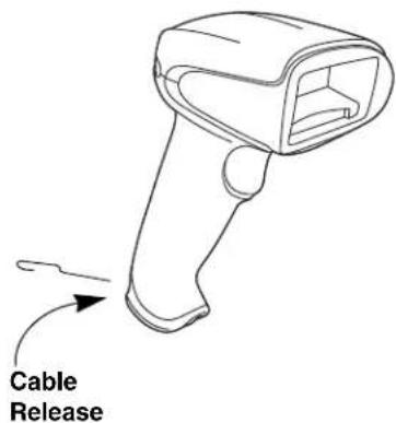
Replacing a Granit Interface Cable
- Turn the power to the host system OFF.
- Disconnect the scanner's cable from the terminal or computer.
- Unscrew the locking plate on the bottom of the scanner.
- Slide the locking plate away from the connector and pull the cable out of the scanner.
- Replace with the new cable.
Insert the connector into the opening and press firmly.
- Slide the locking plate over the base of the connector to secure the cable, and screw the plate into place.
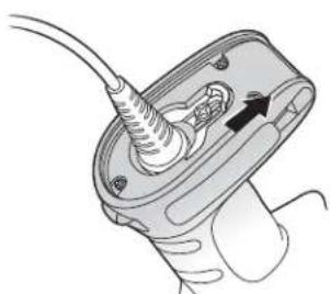
natural_image
Diagram of a mechanical device with a cable inserted into a housing and a hand holding a tool (no text or symbols present)

natural_image
Diagram of a mechanical component with a cable inserted into a housing, showing internal wiring and mounting holes (no text or symbols)
Replacing Cables and Batteries in Cordless Systems
Replacing an Interface Cable in a Base
- Turn the power to the host system OFF.
-
Disconnect the base's cable from the terminal or computer.
-
Turn the base upside down.
-
Pull the connector out while maintaining pressure on the connector release clip.
CCB01-010BT Base:

natural_image
Line drawing of a handheld device with cable and connector, showing internal components and a magnified inset (no text or symbols)
CCB02-100BT/CCB05-100BT Base:

natural_image
Technical line drawing of a mechanical clamp or connector with an inset magnified view showing internal components (no text or symbols)
- Replace with the new cable.
Insert the connector into the opening and press firmly. The connector is keyed to go in only one way, and will click into place.
Changing a Xenon Scanner Battery

-
Use a Phillips head screwdriver to remove the screw from the end cap.
-
Remove the end cap and remove the battery from the handle.
-
Insert replacement battery.
-
Replace end cap and screw.
Changing a Granit Scanner Battery

natural_image
Diagram of a device's internal components showing a close-up view of the main body and a separate housing (no text or symbols present)
- Twist the tab in the bottom of the end cap and open the hinged battery door. (When new, the battery door may stick. Use pliers to twist the tab and open the door until it loosens up.)
- Remove the battery from the handle.
- Insert replacement battery.
- Close the battery door and twist the tab to lock it.
Note: The battery door is designed to pop off the hinge if the scanner is dropped while changing a battery. If this occurs, simply snap it back on.
Troubleshooting a Corded Scanner
The scanner automatically performs self-tests whenever you turn it on. If your scanner is not functioning properly, review the following Troubleshooting Guide to try to isolate the problem.
Is the power on? Is the aimer on?
If the aimer isn't illuminated, check that:
• The cable is connected properly.
- The host system power is on (if external power isn't used).
• The trigger works.
Is the scanner having trouble reading your symbols?
If the scanner isn't reading symbols well, check that the symbols:
- Aren't smeared, rough, scratched, or exhibiting voids.
- Aren't coated with frost or water droplets on the surface.
- Are enabled in the scanner or in the decoder to which the scanner connects.
Is the bar code displayed but not entered?
The bar code is displayed on the host device correctly, but you still have to press a key to enter it (the Enter/Return key or the Tab key, for example).
- You need to program a suffix. Programming a suffix enables the scanner to output the bar code data plus the key you need (such as “CR”) to enter the data into your application. Refer to Prefix/Suffix Overview on page 151 for further information.
The scanner won't read your bar code at all.
- Scan the sample bar codes in the back of this manual. If the scanner reads the sample bar codes, check that your bar code is readable.
Verify that your bar code symbology is enabled (see Chapter 9).
- If the scanner still can't read the sample bar codes, scan All Symbologies On, page 178.
If you aren't sure what programming options have been set in the scanner, or if you want the factory default settings restored, refer to Reset the Factory Defaults on page 257.
Troubleshooting a Cordless System
Troubleshooting a Base
Note: Visit the Services and Support section of our website (www.honeywellaidc.com) to check for the latest software for both the scanner and the base.
If your base is not functioning properly, review the following troubleshooting guidelines to try to isolate the problem.
Is the red LED on?
If the red LED isn't illuminated, check that:
- The power cable is connected properly and there is power at the power source.
- The host system power is on (if external power isn't used).
Is the green LED on?
If the green LED isn't illuminated, check that:
- The scanner is correctly placed in the base.
- There is external power or 12 volt host power.
- Charge mode is turned on. (See "Beeper and LED Sequences and Meaning" on page 48)
- The battery is not bad or deeply discharged. In some cases, the scanner's battery may trickle charge to bring it into an acceptable level and then transition to a normal charge cycle.
Troubleshooting a Cordless Scanner
Note: Make sure that your scanner's battery is charged.
Visit the Services and Support section of our website (www.honeywellaidc.com) to check for the latest software for both the scanner and the base or Access Point.
Is the scanner having trouble reading your symbols?
If the scanner isn't reading symbols well, check that the symbols:
- Aren't smeared, rough, scratched, or exhibiting voids.
- Aren't coated with frost or water droplets on the surface.
- Are enabled in the base or Access Point to which the scanner connects.
Is the bar code displayed but not entered into the application?
The bar code is displayed on the host device correctly, but you still have to press a key to enter it (the Enter/Return key or the Tab key, for example).
- You need to program a suffix. Programming a suffix enables the scanner to output the bar code data plus the key you need (such as “CR”) to enter the data into your application. Refer to Prefix/Suffix Overview on page 151 for further information.
The scanner won't read your bar code at all.
- Scan the sample bar codes in the back of this manual. If the scanner reads the sample bar codes, check that your bar code is readable.
- Verify that your bar code symbology is enabled (see Chapter 9).
- If the scanner still can't read the sample bar codes, scan All Symbologies on page 178.
Symbology Charts
Note: "m" represents the AIM modifier character. Refer to International Technical Specification, Symbology Identifiers, for AIM modifier character details.
Prefix/Suffix entries for specific symbologies override the universal (All Symbologies, 99) entry.
Refer to Data Edit beginning on page 151 and Data Format beginning on page 157 for information about using Code ID and AIM ID.
Linear Symbologies
| AIM Honeywell | |
| Symbology ID | | Possible modifiers (m) | ID Hex | |
| All Symbologies 99 | | | | |
| Codabar ]Fm 0-1 a 61 | | | | |
| Code 11 ]H3 h | 68 | | | |
| Code 128 | ]Cm | 0, 1, 2, 4 | j | 6A |
| Code 32 Pharmaceutical (PARAF) | ]XO | | < | 3C |
| Code 39 (supports Full ASCII mode) | ]Am | 0, 1, 3, 4, 5, 7 | b | 62 |
| TCIF Linked Code 39 (TLC39) | ]L2 | | T 54 | |
| Code 93 and 93i | ]Gm | 0-9, A-Z, a-m | i | 69 |
| EAN | ]Em | 0, 1, 3, 4 | d | 64 |
| EAN-13 (including Bookland EAN) | ]E0 | | d | 64 |
| EAN-13 with Add-On | ]E3 | | d | 64 |
| EAN-13 with Extended Coupon Code | ]E3 | | d | 64 |
| EAN-8 | ]E4 | | D | 44 |
| AIM | Honeywell |
| Symbology | ID | Possible modifiers (m) | ID | Hex |
| EAN-8 with Add-On | ]E3 D 44 | | | |
| GS1 | | | | |
| GS1 DataBar | ]em Oy79 | | | |
| GS1 DataBar Limited | ]em { | 7B | | |
| GS1 DataBar Expanded | ]em} | 7 D | | |
| GS1-128 | ]C1 I 49 | | | |
| 2 of 5 | | | | |
| China Post (Hong Kong 2 of 5) | ]X0 Q 51 | | | |
| Interleaved 2 of 5 | ]lm 0, 1, 3 e 65 | | | |
| Matrix 2 of 5 | ]X0 m 6D | | | |
| NEC 2 of 5 | ]X0 Y 59 | | | |
| Straight 2 of 5 IATA | ]Rm | 0, 1, 3 | f | 66 |
| Straight 2 of 5 Industrial | ]SO | | f | 66 |
| MSI | ]Mm | 0, 1 | g | 67 |
| Telepen | ]Bm | | t | 74 |
| UPC | | 0, 1, 2, 3, 8, 9, A, B, C | | |
| UPC-A | ]EO c 63 | | | |
| UPC-A with Add-On | ]E3 c 63 | | | |
| UPC-A with Extended Coupon Code | ]E3 c 63 | | | |
| UPC-E | ]EO E | 45 | | |
| UPC-E with Add-On | ]E3 E | 45 | | |
| UPC-E1 | ]X0 E | 45 | | |
| Add Honeywell Code ID | | | | 5C80 |
| Add AIM Code ID | | | | 5C81 |
| Add Backslash | | | | 5C5C |
| Batch mode quantity | | | 5 | 35 |
2D Symbologies
| Symbology | AIM | Honeywell |
| ID | Possible modifiers (m) | ID | Hex |
| All Symbologies | | | | 99 |
| Aztec CodeChinese Sensible Code (Han Xin Code) ]X0 H 48 | ]zm | 0-9, A-C | z | 7A |
| Codablock A ]06 0, 1, 4, 5, 6 V 56 | | | | |
| Codablock F ]Om 0, 1, 4, 5, 6 q 71 | | | | |
| Code 49 ]Tm 0, 1, 2, 4 I 6C | | | | |
| Data Matrix | ]dm | 0-6 | w | 77 |
| GS1 | ]em | 0-3 | y | 79 |
| GS1 Composite | ]em 0-3 | y | 79 | |
| GS1 DataBar Omnidirectional | ]em 0-3 | y | 79 | |
| MaxiCode | ]Um | 0-3 | x | 78 |
| PDF417 | ]Lm | 0-2 | r | 72 |
| MicroPDF417 | ]Lm | 0-5 | R | 52 |
| QR Code | ]Qm | 0-6 | s | 73 |
| Micro QR Code | ]Qm | | s | 73 |
Postal Symbologies
| Symbology | AIM | Honeywell |
| ID | Possible modifiers (m) | ID | Hex |
| All Symbologies | | | | 99 |
| Australian Post | ]XO A 41 | | | |
| British Post ]XO B 42 | | | | |
| Canadian Post | ]XO C | 43 | | |
| China Post | ]XO Q 51 | | | |
| InfoMail | ]XO , 2c | | | |
| Intelligent Mail Bar Code | ]XO M | 4D | | |
| Japanese Post | ]XO J | 4A | | |
| KIX (Netherlands) Post | ]XO K | 4B | | |
| Korea Post | ]XO ? | 3F | | |
| Planet Code | ]XO L | 4C | | |
| Postal-4i | ]XO N 4E | | | |
| Postnet | ]XO P | 50 | | |
ASCII Conversion Chart (Code Page 1252)
In keyboard applications, ASCII Control Characters can be represented in 3 different ways, as shown below. The CTRL+X function is OS and application dependent. The following table lists some commonly used Microsoft functionality. This table applies to U.S. style keyboards. Certain characters may differ depending on your Country Code/PC regional settings.
| Non-printable ASCII control characters | Keyboard Control + ASCII (CTRL+X) Mode |
| | | Control + X Mode Off (KBDCAS0) | Windows Mode Control + X Mode On (KBDCAS2) |
| DEC HEX | Char CTRL + | X | | CTRL + X function |
| 0 00 NUL Reserved CTRL+ @ | | | | |
| 1 | 01 | SOH | NP Enter | CTRL+ A | Select all |
| 2 02 STX Caps Lock CTRL+ B | Bold | | | | |
| 3 | 03 | ETX | ALT Make | CTRL+ C | Copy |
| 4 | 04 | EOT | ALT Break | CTRL+ D | Bookmark |
| 5 05 ENQ CTRL Make | CTRL+ E Center | | |
| 6 | 06 | ACK | CTRL Break | CTRL+ F | Find |
| 7 | 07 | BEL | Enter / Ret | CTRL+ G | |
| 8 | 08 | BS | (Apple Make) | CTRL+ H | History |
| 9 | 09 | HT | Tab | CTRL+ I | Italic |
| 10 | 0A | LF | (Apple Break) | CTRL+ J | Justify |
| 11 | 0B | VT | Tab | CTRL+ K | hyperlink |
| 12 | 0C | FF | Delete | CTRL+ L | list, left align |
| 13 | 0D | CR | Enter / Ret | CTRL+ M | |
| 14 | 0E | SO | Insert | CTRL+ N | New |
| 15 | 0F | SI | ESC | CTRL+ O | Open |
| 16 | 10 DLE F11 | | CTRL+ P Print | | |
| 17 | 11 | DC1 | Home | CTRL+ Q | Quit |
| 18 | 12 | DC2 | PrtScn | CTRL+ R | |
| 19 | 13 | DC3 | Backspace | CTRL+ S | Save |
| 20 | 14 | DC4 | Back Tab | CTRL+ T | |
| 21 | 15 | NAK | F12 | CTRL+ U | |
| 22 | 16 | SYN | F1 | CTRL+ V | Paste |
| 23 | 17 | ETB | F2 | CTRL+ W | |
| 24 | 18 | CAN | F3 | CTRL+ X | |
| 25 | 19 | EM | F4 | CTRL+ Y | ? |
| 26 | 1A | SUB | F5 | CTRL+ Z | ? |
| 27 | 1B | ESC | F6 | CTRL+ [ | ? |
| 28 | 1C | FS | F7 | CTRL+ \ | ? |
| 29 | 1D | GS | F8 | CTRL+ ] | ? |
| 30 | 1E | RS | F9 | CTRL+ ^ | ? |
| 31 | 1F | US | F10 | CTRL+ - | ? |
| 127 | 7F | | NP Enter | | ? |
Lower ASCII Reference Table
Note: Windows Code page 1252 and lower ASCII use the same characters.
Printable Characters
| DEC | HEX | Character | DEC | HEX | Character | DEC | HEX | Character |
| 32 2064 40 @ 96 60` | | | | | | |
| 33 21 ! 65 | 41 A 97 61 a | | | | | | |
| 34 22 " 66 | 42 B 98 62 b | | | | | | |
| 35 23 # 67 | 43 C | 99 63 c | | | | | | |
| 36 24 $ 68 | 44 D | 100 | 64 d | | | | | |
| 37 25 % | | 69 45 E 101 | 65 e | | | | | |
| 38 | 26 | & | 70 | 46 | F | 102 | 66 | f |
| 39 | 27 | ' | 71 | 47 | G | 103 | 67 | g |
| 40 | 28 | ( | 72 | 48 | H | 104 | 68 | h |
| 41 | 29 | ) | 73 | 49 | I | 105 | 69 | i |
| 42 | 2A | * | 74 | 4A | J | 106 | 6A | j |
| 43 | 2B | + | 75 | 4B | K | 107 | 6B | k |
| 44 | 2C | , | 76 | 4C | L | 108 | 6C | l |
| 45 | 2D | - | 77 | 4D | M | 109 | 6D | m |
| 46 | 2E | . | 78 | 4E | N | 110 | 6E | n |
| 47 | 2F | / | 79 | 4F | O | 111 | 6F | o |
| 48 30 0 80 | 50 P 112 | 70 p | | | | | | |
| 49 | 31 | 1 | 81 | 51 | Q | 113 | 71 | q |
| 50 | 32 | 2 | 82 | 52 | R | 114 | 72 | r |
| 51 33 3 83 | 53 S 115 | 73 s | | | | | | |
| 52 | 34 | 4 | 84 | 54 | T | 116 | 74 | t |
| 53 | 35 | 5 | 85 | 55 | U | 117 | 75 | u |
| 54 36 6 86 | 56 V 118 | 76 v | | | | | | |
| 55 | 37 | 7 | 87 | 57 | W | 119 | 77 | w |
| 56 38 8 88 | 58 X 120 | 78 x | | | | | | |
| 57 39 9 89 | 59 Y 121 | 79 y | | | | | | |
| 58 | 3A | : | 90 | 5A | Z | 122 | 7A | z |
| 59 | 3B | ; | 91 | 5B | [ | 123 | 7B | { |
| 60 | 3C | < | 92 | 5C | \ | 124 | 7C | | |
| 61 | 3D | = | 93 | 5D | ] | 125 | 7D | } |
| 62 | 3E | > | 94 | 5E | ^ | 126 | 7E | ~ |
| 63 | 3F | ? | 95 | 5F | _ | 127 | 7F | △ |
Extended ASCII Characters
| DEC | HEX | CP 1252 | ASCII | Alternate Extended | PS2 Scan Code |
| 128 | 80 | € | Ç | up arrow ↑ | 0x48 |
| 129 | 81 | | ü | down arrow ↓ | 0x50 |
| 130 | 82 | , é | | right arrow → | 0x4B |
| 131 | 83 | f | â | left arrow ← | 0x4D |
| 132 | 84 | „ | ä | Insert | 0x52 |
| 133 | 85 | ... | à | Delete | 0x53 |
| 134 | 86 | † | å | Home | 0x47 |
| 135 | 87 | ‡ | ç | End | 0x4F |
| 136 | 88 | ^ | ê | Page Up | 0x49 |
| 137 | 89 | ‰ | ë | Page Down | 0x51 |
| 138 | 8A | Š | è | Right ALT | 0x38 |
| 139 | 8B | < | ï | Right CTRL | 0x1D |
| Extended ASCII Characters (Continued) |
| DEC | HEX | CP 1252 | ASCII | Alternate Extended | PS2 Scan Code |
| 140 8C CE | i Reserved n/a | | | | |
| 141 8D i | Reserved n/a | | | | |
| 142 8E Z | A Numeric Keypad Enter | 0x1C | | | |
| 143 8F A | Numeric Keypad / 0x35 | | | | |
| 144 90 É | F1 0x3B | | | | |
| 145 | 91 | ‘ | æ | F2 | 0x3C |
| 146 | 92 | ’ | Æ | F3 | 0x3D |
| 147 | 93 | “ | ô | F4 | 0x3E |
| 148 | 94 | ” | ö | F5 | 0x3F |
| 149 | 95 | • | ò | F6 | 0x40 |
| 150 | 96 | - | û | F7 | 0x41 |
| 151 97 | — ù | | F8 0x42 | | |
| 152 | 98 | - | ÿ | F9 | 0x43 |
| 153 | 99 | TM | Ö | F10 | 0x44 |
| 154 | 9A | § | Ü | F11 | 0x57 |
| 155 | 9B | 〉 | ¢ | F12 | 0x58 |
| 156 | 9C | œ | £ | Numeric Keypad + | 0x4E |
| 157 9D ¥ | | Numeric Keypad - | 0x4A | |
| 158 | 9E | ž | Pts | Numeric Keypad * | 0x37 |
| 159 | 9F | Ÿ | f | Caps Lock | 0x3A |
| 160 | A0 | | á | Num Lock | 0x45 |
| 161 | A1 | i | í | Left Alt | 0x38 |
| 162 | A2 | ¢ | ó | Left Ctrl | 0x1D |
| 163 | A3 | £ | ú | Left Shift | 0x2A |
| 164 | A4 | ☐ | ñ | Right Shift | 0x36 |
| 165 | A5 | ¥ | Ñ | Print Screen | n/a |
| 166 | A6 | | | a | Tab | 0x0F |
| 167 | A7 | § | ° | Shift Tab | 0x8F |
| 168 | A8 | .. | ¿ | Enter | 0x1C |
| 169 | A9 | © | ¬ | Esc | 0x01 |
| 170 | AA | a | ¬ | Alt Make | 0x36 |
| 171 | AB | « | 12 | Alt Break | 0xB6 |
| 172 | AC | ¬ | 14 | Control Make | 0x1D |
| 173 | AD | | i | Control Break | 0x9D |
| 174 | AE | ® | « | Alt Sequence with 1 Character | 0x36 |
| 175 | AF | - | » | Ctrl Sequence with 1 Character | 0x1D |
| 176 B0 ° | | | | | |
| 177 B1 ± | | | | | |
| 178 B22 | | | | | |
| 179 B33 | | | | | |
| 180 B4' | | | | | |
| 181 B5 μ | | | | | |
| 182 B6¶ | | | | | |
| 183 B7' | | | | | |
| 184 B8' | | | | | |
| 185 B91 | | | | | |
| 186 BA | ° | | | | |
| 187 BB | » | | | | |
| 188 BC | 14 | | | | |
| 189 BD | 12 | | | | |
| 190 BE | 34 | | | | |
| 191 BF ¿ | | | | | |
| 192 C0 Å | | L | | | |
| 193 C1 Å | | ⊥ | | | |
| DEC | HEX | CP 1252 | ASCII | Alternate Extended | PS2 Scan Code |
| 194 C2 | | | | | |
| 195 C3 | | | | | |
| 196 C4 | | | | | |
| 197 C5 | | | | | |
| 198 C6 | | | | | |
| 199 C7 | | | | | |
| 200 C8 | | | | | |
| 201 C9 | | | | | |
| 202 CA | | | | | |
| 203 CB | | | | | |
| 204 CC | | | | | |
| 205 CD | | | | | |
| 206 CE | | | | | |
| 207 CF | | | | | |
| 208 D0 | | | | | |
| 209 D1 | | | | | |
| 210 D2 | | | | | |
| 211 D3 | | | | | |
| 212 D4 | | | | | |
| 213 D5 | | | | | |
| 214 D6 | | | | | |
| 215 D7 × | | | | | |
| 216 D8 | | | | | |
| 217 D9 | | | | | |
| 218 DA | | | | | |
| 219 DB | | | | | |
| 220 DC | | | | | |
| 221 DD | | | | | |
| 222 DE | | | | | |
| 223 DF | | | | | |
| 224 E0 | | | | | |
| 225 E1 | | | | | |
| 226 E2 | | | | | |
| 227 E3 | | | | | |
| 228 E4 | | | | | |
| 229 E5 | | | | | |
| 230 E6 | | | | | |
| 231 E7 | | | | | |
| 232 E8 | | | | | |
| 233 E9 | | | | | |
| 234 EA | | | | | |
| 235 EB | | | | | |
| 236 EC | | | | | |
| 237 ED | | | | | |
| 238 EE | | | | | |
| 239 EF | | | | | |
| 240 F0 | | | | | |
| 241 F1 | ± | | | | |
| 242 F2 | ≥ | | | | |
| 243 F3 | ≤ | | | | |
| 244 F4 | | | | | |
| 245 F5 | | | | | |
| 246 F6 | ÷ | | | | |
| 247 F7 | ÷ | ≈ | | | |
| Extended ASCII Characters (Continued) |
| DEC | HEX | CP 1252 | ASCII | Alternate Extended | PS2 Scan Code |
| 248 F8 ø | ^b | | | | |
| 249 F9 ü | | | | | |
| 250 FA ú | | | | | |
| 251 FB ü | ^v | | | | |
| 252 FC ü | ^n | | | | |
| 253 FD y | ^p | | | | |
| 254 FE p | ■ | | | | |
| 255 FF y | | | | | |
ISO 2022/ISO 646 Character Replacements
Code pages define the mapping of character codes to characters. If the data received does not display with the proper characters, it may be because the bar code being scanned was created using a code page that is different from the one the host program is expecting. If this is the case, select the code page with which the bar codes were created. The data characters should then appear properly.
| Code Page Selection Method/ Country | Standard | Keyboard Country | Honeywell Code Page Option |
| United States (standard ASCII) | ISO/IEC 646-IRV n/a | 1 | |
| Automatic National Character Replacement | ISO/IEC 2022 | n/a | 2 (default) |
| Binary Code page | n/a | n/a | 3 |
| Default “Automatic National Character replacement” will select the below Honeywell Code Page options for Code128, Code 39 and Code 93. |
| United States | ISO/IEC 646-06 0 | 1 | |
| Canada | ISO /IEC 646-121 | 54 | 95 |
| Canada | ISO /IEC 646-122 | 18 | 96 |
| Japan | ISO/IEC 646-14 | 28 | 98 |
| China | ISO/IEC 646-57 | 92 | 99 |
| Great Britain (UK) | ISO /IEC 646-04 7 | 87 | |
| France | ISO /IEC 646-69 3 | 83 | |
| Germany | ISO/IEC646-21 | 4 | 84 |
| Switzerland | ISO /IEC 646-CH | 6 | 86 |
| Sweden / Finland (extended Annex C) | ISO/IEC 646-11 | 2 | 82 |
| Ireland | ISO /IEC 646-207 | 73 | 97 |
| Denmark | ISO/IEC 646-08 | 8 | 88 |
| Norway | ISO/IEC 646-60 | 9 | 94 |
| Italy | ISO/IEC 646-15 | 5 | 85 |
| Portugal | ISO/IEC 646-16 | 13 | 92 |
| Spain ISO/IEC 646-17 10 90 | | | |
| Spain ISO/IEC 646-85 51 91 | | | |
| Dec | 353664919293 | | | | | 9496123124125126 | | | |
| Hex | 2324405B5C5D | | | | | 5E607B7C7D7E | | | |
| US01#@[\]^~ | | | | | | | | | | | |
| CA | 5495 | | #àçêîôé | ù | è | û | | | | | | | |
| CA | 1896 | | #àçêÉôé | ù | è | û | | | | | | | |
| JP2898 | | | #@[¥]^ | {I} | | | | | | | | | - |
| CN | 9299 | | #¥@[\] | ^{} | | | } | | | | | | | - |
| GB | 787 | | £ | | @ | [ | \ | ] | ^ | ` | | | | |
| FR383 | | | £ | | à | ° | ç | § | ^ | μ | é | ù | è |
| DE | 484 | | # | | § | Ä | Ö | Ü | ^ | ` | ä | ö | ü |
| CH | 6 | 86 | ùàçêîô | ä | ö | üû | | | | | | | |
| SE/FI | 2 | 82 | # | ü | É | Ä | Ö | Ä | Ü | é | ä | ö | å |
| DK | 8 | 88 | # | | @ | Æ | ∅ | Ä | ^ | ` | æ | ø | å |
| NO9 | 94 | | # | | @ | Æ | ∅ | Ä | ^ | ` | æ | ø | å |
| IE7397 | | | £ | | Ó | É | í | Ú | Á | ó | é | í | ú |
| IT | 585 | | £ | | § | ° | ç | é | ^ | ù | à | ò | è |
| PT1392 | | | # | | § | Ä | ç | Ö | ^ | ` | ã | ç | õ |
| ES | 1090 | | # | | § | i | Ñ | ¿ | ^ | ` | ° | ñ | ç |
| ES | 5191 | | # | $ | · | ¡ | Ñ | ç | ¿ | ` | ` | ñ | ç |
| COUNTRY | Country Keyboard | Honeywell CodePage | ISO / IEC 646 National Character Replacements |
Keyboard Key References
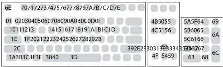
104 Key U.S. Style Keyboard
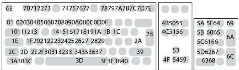
105 Key European Style Keyboard
Sample Symbols

Sample Symbols (Continued)
Postnet
Zip Code
Data Matrix

Test Symbol
QR Code

Numbers
MaxiCode

Test Message
Micro PDF417
Test Message
Programming Chart

Programming Chart (Continued)

Note: If you make an error while scanning the letters or digits (before scanning Save), scan Discard, scan the correct letters or digits, and Save again.
Honeywell
9680 Old Bailes Road
Fort Mill, SC 29707
www.honeywellaidc.com