
MediaCento IPX PoE - Audio/video extension Black Box - Free user manual and instructions
Find the device manual for free MediaCento IPX PoE Black Box in PDF.


| Product Type | Audio/Video Extender over IP |
| Model | MediaCento IPX PoE |
| Brand | Black Box |
| Dimensions (WxDxH) | 4.7 x 3.0 x 1.2 in (12 x 7.6 x 3 cm) |
| Weight | 0.55 lb (0.25 kg) |
| Power Supply | PoE (Power over Ethernet) 802.3af |
| Video Interface | HDMI 1.4 |
| Max Resolution | 1080p @ 60Hz |
| Max Transmission Distance | 330 ft (100 m) via Cat5e/6 |
| Audio Support | Stereo audio embedded in HDMI |
| Latency | < 1 frame |
| Operating Temperature | 32 to 122°F (0 to 50°C) |
| Storage Temperature | -4 to 158°F (-20 to 70°C) |
| Humidity | 10% to 90% non-condensing |
| LED Indicators | Power, Link, Video |
| Mounting | Desktop or wall-mountable with optional bracket |
| Included Accessories | Quick start guide, mounting screws |
| Maintenance | Keep vents clean; use dry cloth for cleaning |
| Safety Certifications | CE, FCC Class A |
| Spare Parts / Repairability | No user-serviceable parts; contact Black Box support |
Frequently Asked Questions - MediaCento IPX PoE Black Box
User questions about MediaCento IPX PoE Black Box
0 question about this device. Answer the ones you know or ask your own.
Ask a new question about this device
Download the instructions for your Audio/video extension in PDF format for free! Find your manual MediaCento IPX PoE - Black Box and take your electronic device back in hand. On this page are published all the documents necessary for the use of your device. MediaCento IPX PoE by Black Box.
USER MANUAL MediaCento IPX PoE Black Box
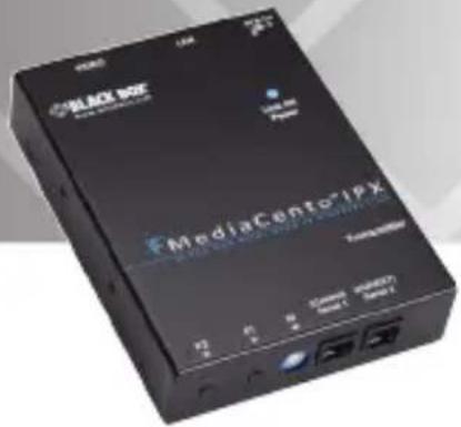
MediaCento™ IPX with PoE
Extend audio and video signals via an existing LAN.
Distribute HDMI video to an unlimited number of displays using IP multicast, or make eye-catching video walls of up to 8 x 8 displays.

Customer Support Information
Order toll-free in the U.S.: Call 877-877-BBOX (outside U.S. call 724-746-5500) • FREE technical support 24 hours a day, 7 days a week: Call 724-746-5500 or fax 724-746-0746 • Mailing address: Black Box Corporation, 1000 Park Drive, Lawrence, PA 15055-1018
Web site: www.blackbox.com • E-mail: info@blackbox.com
Trademarks Used in this Manual
Black Box and the Double Diamond logo are registered trademarks, and MediaCento is a trademark, of BB Technologies, Inc.
Bonjour and Apple are registered trademarks of Apple, Inc.
Windows is a registered trademark of Microsoft Corporation.
UL is a registered trademark of Underwriters' Laboratories.
Any other trademarks mentioned in this manual are acknowledged to be the property of the trademark owners.
FEDERAL COMMUNICATIONS COMMISSION AND INDUSTRY CANADA RADIO FREQUENCY INTERFERENCE STATEMENTS
This equipment generates, uses, and can radiate radio-frequency energy, and if not installed and used properly, that is, in strict accordance with the manufacturer's instructions, may cause interference to radio communication. It has been tested and found to comply with the limits for a Class A computing device in accordance with the specifications in Subpart B of Part 15 of FCC rules, which are designed to provide reasonable protection against such interference when the equipment is operated in a commercial environment. Operation of this equipment in a residential area is likely to cause interference, in which case the user at his own expense will be required to take whatever measures may be necessary to correct the interference.
Changes or modifications not expressly approved by the party responsible for compliance could void the user's authority to operate the equipment.
This digital apparatus does not exceed the Class A limits for radio noise emission from digital apparatus set out in the Radio Interference Regulation of Industry Canada.
2.3.1 Multicast, Unicast, and Video Wall Transmitters and Receivers....10
2.3.2 Multicast Transmitter and Receiver Exclusive Functions...... 11
2.4 What's Included 11
2.5 Additional Items You Will Need 12
2.6 Hardware Description....12
2.6.1 Transmitters 12
2.6.2 Receivers 15
2.6.3 Indicators 18
2.6.4 Function Buttons (F1 and F2) 18
2.6.5 EDID Copy 19
- Installation 20
- Configuration 22
4.1 Basic Configuration 22
4.2 Advanced Configuration 22
4.2.1 Accessing through Serial 23
4.2.2 Accessing through Telnet 23
- Advanced Commands....25
5.1 Advanced IP Commands 26
5.2 Advanced Multicast IP Configuration 27
5.2.1 Transmitter....29
5.2.2 Receiver 29
5.3 Serial Extension 29
5.4 Telnet Extension 30
6 Accessing the Web Interface....33
6.1 Accessing the Transmitter without an IP Address....33
6.2 Accessing the Web Interface for a Transmitter or Receiver with an IP Address....35
- Video Wall Features .... 36
- Troubleshooting 43
8.1 Problems/Solutions....43
8.2 Contacting Black Box 43
8.3 Shipping and Packaging....44
Appendix: Connector Pinouts....45
1. Specifications
Technical Specifications
| Approvals FCC, TUV, CE, UL | ®, CSA, RoHS, WEEE |
| Bandwidth 120 Mbps maximum | |
| Default IP Address 169. | 254.x.x (with no DHCP address)NOTE: To find the IP address of any receiver, simply connect to monitor and power up to get IP address. To find the IP address of any other receiver or transmitter, use Telnet to connect to any device in the system and use a “node_list” command or connect with the serial interface. |
| Distance From CPU to TX | 16 ft. (5 m) maximum, HDMI;Between TX and RX: 328 ft. (100 m)* maximum*NOTE: Use a network switch to get greater distances. |
| Efficiency Level Level IV | |
| Heat Dissipation 3.41 BTU/hr. | |
| HDCP Supported | |
| Latency 2 frames (33 ms) maximum | |
| Leads Supported HDMI | video and RS-232 |
| MTBF 90,000 hours | |
| User Controls (1) 16-position rotary selection switch,(2) Function buttons: (1) F1, (1) F2 | |
| Connectors (1) HDMI female, (1) RJ-45 interconnect/LAN connection, (1) 2.1-mm barrel connector for power, (2) RJ-12 6P6C††NOTE: Only 4 center pins are used at this time. | |
| Indicators (1) LED for Link and Power; (1) LED for Network Activity | |
| Environmental Temperature Tolerance: Operating: 32 to 104° F (0 to 40° C); Storage: -4 to +140° F (-20 to +60° C) Humidity Tolerance: Operating: 80%, noncondensing; Altitude: 10,000 ft. (3048 m) maximum | |
| Power Input: 100–240 VAC, 50/60 Hz, 0.6 A; Output: 12 VDC; Consumption: 13.5 W; Power Supply Cord Length: 6 ft. (1.8 m) | |
| Power over Ethernet (PoE) | Complies with IEEE 802.3af standard; Power: Nominal Input: 48 VDC; Input Range: 36–57 VDC |
| Size 0.98"H x 3.77"W x | 5.11"D (2.5 x 9.6 x 12.9 cm) |
| Weight 1.1 lb. (0.5 kg) | |
2. Overview
2.1 Introduction
The MediaCento IPX with PoE is a perfect solution for audio and video signal extension via an existing Local Area Network (LAN) system. With multicast technology, one local unit can drive multiple remote units with no extra network load. There are 16 selectable channels that can be used to transmit to multiple receivers. In a network that supports IGMP (Layer 2 or Layer 3 switches), each channel can connect to unlimited displays in video wall applications and unlimited displays in a multicast application using a standard IT Ethernet structure on a LAN system.
The MediaCento IPX with PoE supports Full HD 1080p, is HDCP compliant, is Blu-ray ready, and supports Power over Ethernet (PoE). It can handle applications that require greater distance, high speed transmission, real-time high video resolution, security, and noise immunity. It is ideal for situations that need live presentation, such as public broadcasting, education centers, boardrooms, etc.
2.2 Available Models
Three transmitter/receiver pairs are available, and they are ordered separately by part number. Choose from:
- MediaCento IPX Multicast Transmitter (VX-HDMI-POE-MTX) and MediaCento IPX Multicast Receiver (VX-HDMI-POE-MRX)
- MediaCento IPX Unicast Transmitter (VX-HDMI-POE-UTX) and MediaCento IPX Unicast Receiver (VX-HDMI-POE-URX)
- MediaCento IPX Video Wall Transmitter (VX-HDMI-POE-VTX) and MediaCento IPX Video Wall Receiver (VX-HDMI-POE-VRX)
2.3 Features
2.3.1 Multicast, Unicast, and Video Wall Transmitters and Receivers
- Extend high definition video signal over LAN (dependent on network performance).
- Power over Ethernet: - Fully support IEEE Std. 802.3af-2003 - Input Voltage Range 36V to 57V
- Choose from 16 selections on the DIP rotary switch for pairing.
- Provide automatic EDID configuration.
- Use well-developed Ethernet technology and TCP/IP communication protocol.
- Transmitters and Receivers are HDCP-compliant and Blu-ray ready.
- HDTV compatible; support 1080p, 1080i, 720p, 720i.
- Compatible with popular screen resolutions: XGA, SXGA, UXGA, WSXGA.
2.3.2 Multicast Transmitter and Receiver Exclusive Functions
- Each transmitter can be multicast to up to an unlimited number of displays in video wall applications or unlimited displays in multicast applications.
- Use an IGMP network to prevent network flooding.
2.4 What's Included
All units:
• (1) U.S. power supply
• (1) U.S. power cord
• (4) foot pads
- This user manual
VX-HDMI-POE-MTX also has:
• (1) MediaCento IPX Multicast Transmitter
• (1) DB9 F to RJ-11 adapter
• (1) RJ-11 to RJ-11 cable
VX-HDMI-POE-MRX also has:
• (1) MediaCento IPX Multicast Receiver
• (1) MediaCento IPX Unicast Transmitter
• (1) DB9 F to RJ-11 adapter
• (1) RJ-11 to RJ-11 cable
VX-HDMI-POE-UTX also has:
VX-HDMI-POE-URX also has:
• (1) MediaCento IPX Unicast Receiver
• (1) MediaCento IPX Video Wall Transmitter
VX-HDMI-POE-VTX also has:
• (1) DB9 F to RJ-11 adapter
• (1) RJ-11 to RJ-11 cable
VX-HDMI-POE-VRX also has:
• (1) MediaCento IPX Video Wall Receiver
2.5 Additional Items You Will Need
• HDCP-compliant monitors with HDMI interface for the HDCP video source
- CAT5/5e/6 UTP cable (EIA/TIA 568B industry-standard compliant)
- Layer 2 or 3 switches with IGMP and optional Power over Ethernet (PoE)
2.6 Hardware Description
NOTE: All six transmitter/receiver models have the same connectors, but with different functions.
2.6.1 Transmitters

Figure 2-1. Transmitter front panel.

Figure 2-2. Transmitter back panel.
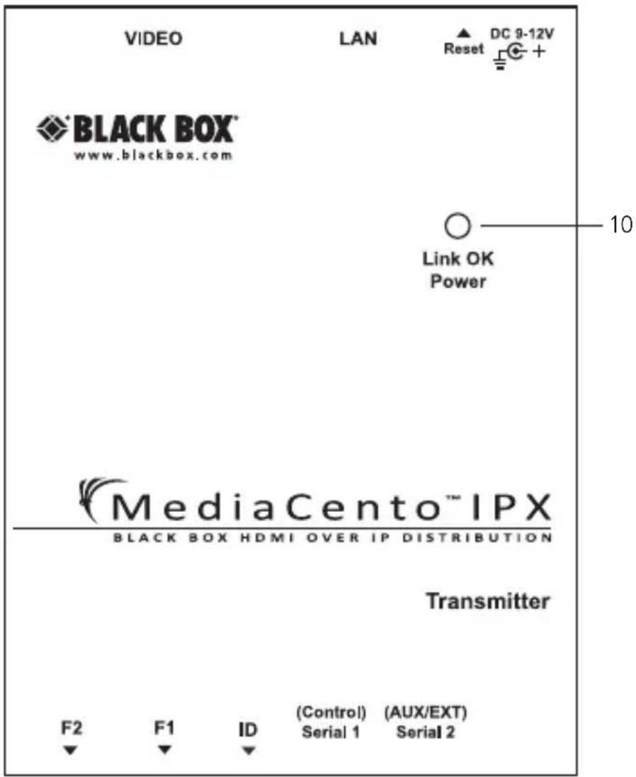
Figure 2-3. Transmitter top panel.
Table 2-1. Components of the Transmitters.
| Number Component Description | ||
| 1 F2 button See Section 2.6.4. | ||
| 2 F1 button See Section 2.6.4. | ||
| 3 Rotary switch | Set up an identical position for all units | |
| 4 RJ-12 connector Serial port 1: For system control | ||
| 5 RJ-12 connector Serial port 2: For data transfer | ||
| 6 | Locking barrel connector for power | Links to power supply (not required with PoE switch) |
| 7 Network Status LED | Flashing: Connected to network Goes off once: Abnormal | |
| 8 RJ-45 jack | Connects to the 10-/100-/1000-Mbps network switch and supplies PoE | |
| 9 Video connector HDMI source | ||
| 10 Power/Link LED | Green: Power on Interlaced flashing Blue + Green: Link w/o videoBlue: Link OK | |
2.6.2 Receivers

Figure 2-4. Receiver front panel.

Figure 2-5. Receiver back panel.

Figure 2-6. Receiver top panel.
Table 2-2. Components of the Receivers.
| Number Component Description | ||
| 1 F2 button See Section 2.6.4. | ||
| 2 F1 button See Section 2.6.4. | ||
| 3 Rotary switch | Set up an identical position for all units | |
| 4 RJ-12 connector Serial port 1: For system control | ||
| 5 RJ-12 connector Serial port 2: For data transfer | ||
| 6 | Locking barrel connector for power | Links to power supply (not required with PoE switch) |
| 7 Network Status LED | Flashing: Connected to network Goes off once: Abnormal | |
| 8 RJ-45 jack | Connects to the 10-/100-/1000-Mbps network switch and supplies PoE | |
| 9 Video connector Connects to the HDMI monitor | ||
| 10 Power/Link LED | Red: Power on Interlaced flashing Blue + Red: Link without video Blue: Link OK | |
2.6.3 Indicators
The LEDs on the extender units show the real-time status indicating the linking and communication between the Transmitter/Sender unit and the Receiver unit. Users can identify the current status through the LED indicators on the unit.
The quality of the output signal will depend largely upon the quality of the video source, cable, and display device used. Low-quality cables degrade output signals, causing elevated noise levels. Use the proper cable and make sure the display device can handle the resolution and refresh rate selected.
NOTE: The system will disable the video output signal when it detects non-HDCP-compliant display(s) trying to play on the HDCP video source. All the connected output displays MUST be HDCP compliant when the video source is HDCP compliant.
2.6.4 Function Buttons (F1 and F2)
The Function buttons (F1 and F2) on the extender units operate as described in Table 2-3.
Table 2-3. Function buttons.
| Button Action Description | ||
| F2 Press for 1 second. | Toggle between graphics and video mode. | |
| F2 | 1. Press and hold the F2 button.2. Apply power to the receiver unit.3. Release right after the Network Status LED starts blinking. | EDID copy (Receiver unit only!) |
| F2 Press for 5 seconds. | Change anti-dithering mode | |
| F1 Press for 1 second. Link/Unlink connection | ||
| F1 | Press and hold the F1 button.Apply power to the unit.Release right after the Network Status LED starts blinking.Power cycle the unit. | Resets the box to factory defaults. |
2.6.5 EDID Copy
Copying the EDID will enable the receiver to send correct resolutions to your output. Although the default EDID will work in most cases, some monitors will not work with it.
NOTE: EDID copy is required for DVI monitors.
To copy the EDID:
- To copy EDID from a specific receiver to a specific transmitter, both receiver and transmitter must be configured to the same channel.
- Hold down the function button on the receiver and plug in the power.
- Continue to hold down the function button until the network LED starts blinking. EDID is now copied to the receiver.
3. Installation
WARNINGS:
Make sure that all devices are powered off before connecting to the unit.
Make sure all devices you will connect are properly grounded.
Place cables away from fluorescent lights, air conditioners, and machines.
NOTE: EDID copy is required for DVI monitors.
System Requirements for PoE
- Ensure that a PSE device supports PoE function.
- Ensure that a PSE device can provide sufficient power on the Ethernet cable.
- STP and FTP cabling are recommended.
Installing the Transmitter and Receiver
- Connect a video source (PC, Blu-ray, etc.) to the Transmitter/Sender Unit.
- Connect the monitor to the Receiver Unit with an HDMI cable.
NOTE: IF the source has HDCP, the monitor must support HDCP. - Connect transmitter and receivers to the desired network with a Layer 2/3 IGMP switch using CATx cables.
- Set matching TX/RX to the same rotary position (see Section 4.1, Basic Configuration).
- Apply the proper power to all connecting devices.
- Monitors connected to receiver units will show IP address before connecting.
NOTE: Figure 3-1 shows this installation.

flowchart
graph TD
    subgraph Top
        A["TX"] --> B["Layer 2/3 switch with IGMP"]
        C["Blu-ray"] --> B
        D["PC"] --> B
        E["DVD player"] --> B
        F["RX"] --> G["Monitor"]
        H["RX"] --> I["Monitor"]
        J["RX"] --> K["Monitor"]
    end
    B --> L["Monitor"]
    B --> M["Monitor"]
    B --> N["Monitor"]
    B --> O["Monitor"]
    B --> P["Monitor"]
    style Top fill:#f9f,stroke:#333
    style Bottom fill:#ccf,stroke:#333
Figure 3-1. Installation diagram.
4. Configuration
4.1 Basic Configuration
The rotary switch on each device decides the channel of the device when booting.
For a receiver or receivers to connect to a transmitter, they must be on the same channel. Each transmitter should be on a separate switch setting and the receivers should be on the same switch setting as the desired transmitter. After you change the switch setting, you must reboot the device for the changes to take effect.
4.2 Advanced Configuration
Advanced configuration is not needed but is available.
You can access devices through the serial interface or Telnet for advanced configuration of network settings.
A serial/Telnet client is needed.
To see the IP address of a receiver:
Connect a receiver to a monitor and power on. Device information, including the IP address, will be in the lower right corner. Reset the receiver if needed. If the receiver is set to DHCP IP mode, a network connection is required.
4.2.1 Accessing through Serial
- Using the client, select "serial" and enter "115200" for the speed (baud rate).
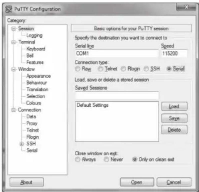
Figure 4-1. PuTTY configuration screen using serial.
- No username or password is required. Just press enter.
4.2.2 Accessing through Telnet
- Using the client, enter in the IP address of the device.
- Change the port to 24.
Chapter 4: Configuration
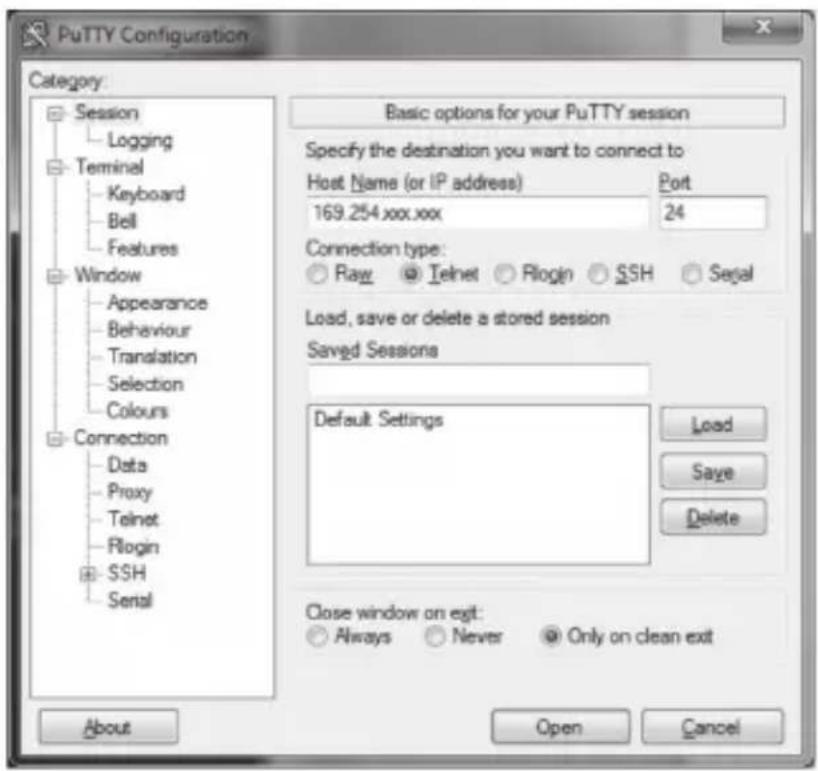
Figure 4-2. PuTTY configuration screen using Telnet.
- The default password is root.
5. Advanced Commands
These are advanced configurations and require knowledge of IP networking protocols and multicasting. Do not attempt to run any commands, modify files, or change any other settings apart from the specific configurations noted here.
All commands are case-sensitive.
To list names and IP information of all connected MediaCento IPX devices, type in: node_list

Figure 5-1. Names and IP information list.
To view all current configured parameters, type in: astparam dump
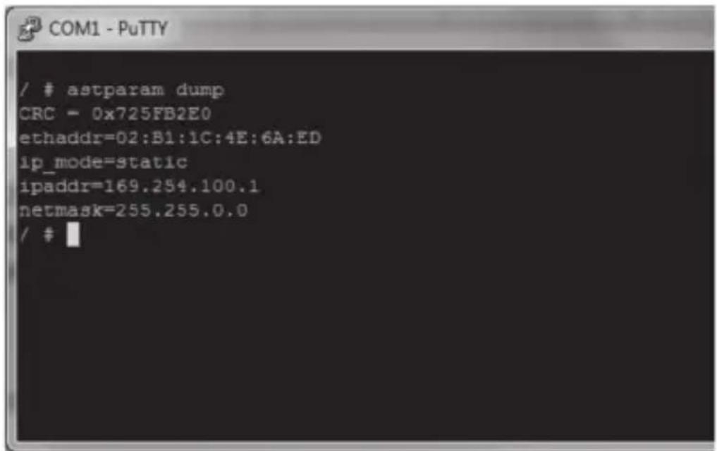
Figure 5-2. Current configured parameters list.
To reset to factory default, setting the IP mode to autoip and removing any overrides, type in:
reset_to_default.sh
To change the baud rate of the serial extension interface, type in:
stty X -F /dev/ttyS0
(replace X with desired baud rate)
To disable/enable the link for a specific device, type in:
ast_send_event -1 e_stop_link
ast_send_event -1 e_reconnect
5.1 Advanced IP Commands
Each device has three possible modes of establishing an IP address: autoip, dhcp, and static.
- AutoIP is the default mode and it will always automatically assign available IP addresses in the private IP domain 169.254.xxx.xxx
NOTE: The MediaCento IPX uses the Avahi zeroconf protocol to find an available IP in the 169.254.xxx.xxx range.
- DHCP client gets an address from the local DHCP server.
CAUTION: Make sure a DHCP client is connected or problems will occur.
- Static allows you to manually change the IP address and netmask of the device. This requires further input before reboot.
To change the IP mode, type in:
astparam s ip_mode
astparam save (saves changes)
reboot (reboots the device)
If static is selected, the following commands are needed before reboot. Type in:
astparam s ipaddr xxx.xxx.xxx.xxx (enter IP address for x's)
astparam s netmask xxx.xxx.xxx.xxx (enter netmast for x's)
astparam save (saves changes)
reboot
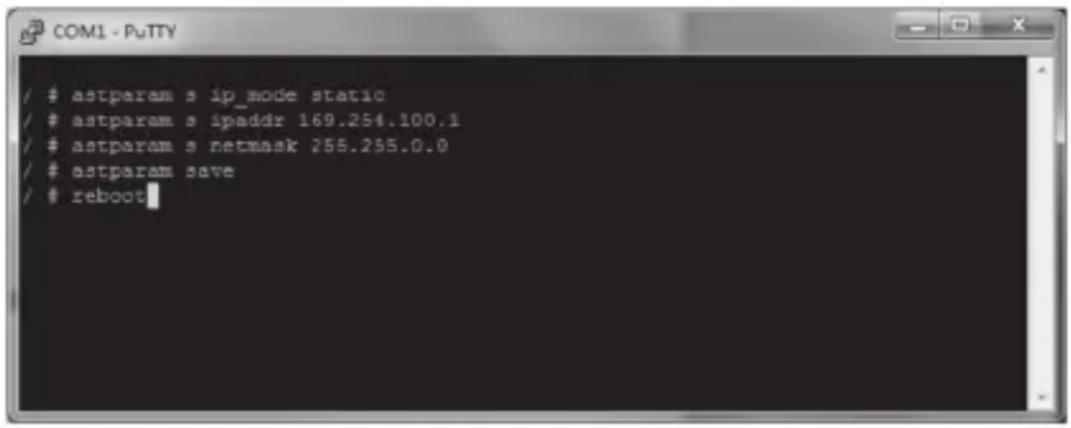
Figure 5-3. COM1 PuTTY screen.
5.2 Advanced Multicast IP Configuration
Predefined multicast addresses can be selected by using the rotary switch buttons on the devices (recommended). See Table 5-1 for listing of channels:
Table 5-1. Channel listing for multicast address.
| Multicast Address | Channel IDs | ||||
| B0 | B1 | B2 | B3 | ID | |
| 225.0. 0. 0 0 0 0 | |||||
| 225.0. 1. 0 0 0 1 | |||||
| 225.0. 0. 1 0 0 2 | |||||
| 225.0. 1. 1 0 0 3 | |||||
| 225.0. 0. 0 1 0 4 | |||||
| 225.0. 1. 0 1 0 5 | |||||
| 225.0. 0. 1 1 0 6 | |||||
| 225.0. 1. 1 1 0 7 | |||||
| 225.0. 0. 0 0 1 8 | |||||
| 225.0. 1. 0 0 1 9 | |||||
| 225.0. 0. 1 0 1 A | |||||
| 225.0. 1. 1 0 1 B | |||||
| 225.0. 0. 0 1 1 C | |||||
| 225.0. 1. 0 1 1 D | |||||
| 225.0. 0. 1 1 1 E | |||||
| 225.0. 1. 1 1 1 F | |||||
To override the DIP rotary switch, use the commands shown on the next page for each device:
NOTE: B0, B1, B2, and B3 refer to the values in Table 5-1.
5.2.1 Transmitter
To change the multicast group IP, type in:
astparam s multicast_ip 225.0.B0.B1B2B3
To change the hostname ID of the transmitter, type in:
astparam s hostname_id B0B1B2B3
ast_send_event -1 e_chg_hostname
To override DIP rotary switch setting on bootup:
astparams reset_ch_on_boot n (space between boot and the n)
astparam save
reboot
5.2.2 Receiver
To change the multicast group IP, type in:
astparam s multicast_ip 225.0.B0.B1B2B3
To change the transmitter channel read:
astparam s ch_select B0B1B2B3
To override DIP rotary switch setting on bootup, type in:
astparams reset_ch_on_boot n (space between boot and the n)
astparam save
reboot
5.3 Serial Extension
Serial extension can be done from one transmitter to all linked receivers. Telnet serial extension is also available as a replacement of serial. Serial extension information:
Default baud rate: 9600 (unless changed manually)
Data bits: 8
Parity: Even
Stop bits: 1
Flow control: None
NOTE: This is a two-way communication. The transmitter will receive any data sent from the serial devices connected to the receivers.

Figure 5-4. Options controlling local serial lines.
For both transmitter and receiver units, the added RJ-11 to DB9 serial cable needs to be connected to the second serial port on the devices.
5.4 Telnet Extension
Telnet serial extension allows for serial output from a receiver through a Telnet connection. This disables serial input coming from a transmitter but allows for 2-way communication to specific devices.
NOTE: Telnet extension requires custom firmware. For details, contact Black Box Technical Support at 724-746-5500 or info@blackbox.com.
To set up a Telnet extension:
- Using a Telnet protocol, use Port 6752.

Figure 5-5. Setting up Telnet extension using a Telnet protocol.
- Turn off line echo and local line editing.

Figure 5-6. Turning off line echo and local line editing.
6. Accessing the Web Interface
The Web interface can be used to view information about the device, upload a firmware file to the device, and for video wall transformers configuration. The Web interface will not give network information or screen previews.
6.1 Accessing the Transmitter without an IP Address
You can access the transmitter directly with a serial connection, and find the IP address using the "node-list" command. See Chapter 5. To connect without an IP address or serial connection, access the Web interface.
Bonjour® is needed to access the Web interface. Apple ® products usually have this installed. If needed, you can download the free version from http://www.apple.com/kb/DL999 and click the "Print Server" link.
- Run Bonjour.
- Configure the control PC's network setting as 169.254.xxx.xxx IP domain with netmask 255.255.0.0. Default gateway and DNS can be left blank. For Windows ^® 7: http://windows.microsoft.com/en-us/windows7/change-tcp-ip-settings.
- Open a Web browser and insert the address: http://ast-gatewayXXXX.local. The four digits after ast-gateway depend on the position of the Rotary Switch you've set. Please refer to Table 6-1. For example, if the position is set up as 7, then the address should be http://ast-gateway1110.local
Table 6-1. Rotary Switch position settings.
| Position | Four-digit setting Position | Four-digit setting |
| 0 0000 8 0001 | ||
| 1 1000 9 1001 | ||
| 2 0100 A 0101 | ||
| 3 110 0 B 1101 | ||
| 4 0010 C 0011 | ||
| 5 1010 D 1011 | ||
| 6 0110 E 0111 | ||
| 7 1110 F 1111 |

Figure 6-1. Setup screen (without IP address).
6.2 Accessing the Web Interface for a Transmitter or Receiver with an IP Address
-
Configure the control PC's network setting as 169.254.xxx.xxx IP domain with netmask 255.255.0.0. Default gateway and DNS can be left blank. For Windows 7: http://windows.microsoft.com/en-us/windows7/change-tcp-ip-settings
-
Open a Web browser and insert the IP address of the device.
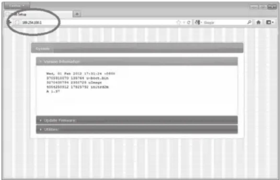
Figure 6-2. Web setup screen (with IP address).
7. Video Wall Features
Using the Video Wall features, you can send video and audio to unlimited outputs through IP. Format the video wall so that separate sections of the video can be sent to different outputs. Basic settings allow for bezel compensation and different arrays of screens. Advanced settings allow for video manipulation to specific outputs. Figure 7-1 shows a typical application:

flowchart
graph LR
    A["PC"] --> B["MediaCento™ IPX Multicast Transmitter (VX-HDMI-POE-MTX)"]
    B --> C["MediaCento™ IPX Multicast Receivers (VX-HDMI-POE-MRX)"]
    C --> D["Digital displays"]
    D --> E["IP"]
    E --> F["Layer 3 switch with IGMP"]
    F --> G["CATx cable"]
    G --> H["PC"]
    I["HDMI cable"] --> B
    J["IP"] --> E
    K["CATx cables"] --> L["Layer 3 switch with IGMP"]
    L --> M["Digital displays"]
    M --> N["HDMI cables"]
Figure 7-1. Sample installation.
Video Wall Setup
Figure 7-2 shows the Basic Setup screen for the VX-HDMI-POE-VTX and VRX. Table 7-1 describes its components.

Figure 7-2. Basic Setup screen.
Table 7-1. Basic Setup screen components.
| Component Description | |
| Bezel and Gap Compensation | Dimensions of screen (inside and outside width and height). |
| Wall Size and Position Layout | Select number of vertical and/or horizontal monitors, row position, and column position. |
| Apply To: “All” device(s) in the list | Click on the “Apply” button to apply settings. |
| Show OSD checkbox | Check this box to output each receiver's specific number to the connected monitor. |
Figure 7-3 shows the Advanced Setup screen. Table 7-2 describes its components.

Figure 7-3. Advanced Setup screen.
Table 7-2. Advanced Setup screen components.
| Component Description | |
| Step 1: Choose control target | Click on the arrows and buttons to select a control target. |
| Show OSD checkbox | Check this box to output each receiver's specific number to the connected monitor. |
| Step 2: Control options | |
| Reset to Basic Setup, Single Host Mode checkbox | Check this box, then press the “Reset” button. |
| Screen Layout (Row x Column) | Select the number of rows and columns from the drop-down menu, then click on the “Apply” button. |
| Row Position | Select the row from the drop-down menu, then click on the “Apply” button. |
| Column Position | Select the column from the drop-down menu, then click on the “Apply” button. |
| Horizontal Shift (N*8 pixels) | Use to shift video output horizontally, then click on the “Apply” button. |
| Vertical Shift (HOST: N pixelsCLIENT: N*8 pixels) | Use to shift video output vertically, then click on the “Apply” button. |
Figure 7-4 shows the Advanced Commands screen. Table 7-3 describes its components.

Figure 7-4. Advanced Commands screen.
Table 7-3. Advanced Commands screen components.
| Component Description | |
| Screen Layout (Row x Column) | Select the number of rows and columns from the drop-down menu, then click on the “Apply” button. |
| Row Position | Select the row from the drop-down menu, then click on the “Apply” button. |
| Column Position | Select the column from the drop-down menu, then click on the “Apply” button. |
| Horizontal Shift (N*8 pixels) | Use to shift video output horizontally, then click on the “Apply” button. |
| Vertical Shift (HOST: N pixelsCLIENT: N*8 pixels) | Use to shift video output vertically, then click on the “Apply” button. |
| Horizontal Scale Up (N pixels/ column_count) | Use to scale video output horizontally, then click on the “Apply” button. |
| Vertical Scale Up (N pixels/ column_count) | Use to scale video output vertically, then click on the “Apply” button. |
| Tearing Delay (μs) | Use to compensate for screen tearing, then click on the “Apply” button. |
| Console API Command | Type in the Console API Command, then click on the “Apply” button. |
8. Troubleshooting
8.1 Problem/Solutions
Problem: No video on monitor at bootup.
Solutions:
- Check the device power using the Link/Power LED.
- Check the network connection using the Network LED.
- Check the video connection using the Link/Power LED.
- Make sure that the DIP rotary switch is set to the correct ID.
NOTE: If manually changed, make sure the IDs match.
- If you're using a mix of multicast and unicast units, make sure they match up correctly.
- Set your display device's (TV, monitor, etc.) input source as HDMI.
- Check the PC BIOS configuration for the video output setting.
- Connect your computer to the HDMI Display DIRECTLY to check if the video signal gets through.
- Make sure the DVI monitor is using the correct EDID. See Section 2.6.5 for details.
Problem: Video is of lower quality than input video.
Solutions:
- Check that network settings are configured correctly.
- Check if anti-dithering is turned off.
8.2 Contacting Black Box
If you determine that your MediaCento IPX with PoE is malfunctioning, do not attempt to alter or repair the unit. It contains no user-serviceable parts. Contact Black Box Technical Support at 724-746-5500 or info@blackbox.com.
Before you do, make a record of the history of the problem. We will be able to provide more efficient and accurate assistance if you have a complete description, including:
- the nature and duration of the problem.
-
when the problem occurs.
-
the components involved in the problem.
- any particular application that, when used, appears to create the problem or make it worse.
8.3 Shipping and Packaging
If you need to transport or ship your MediaCento IPX with PoE:
- Package it carefully. We recommend that you use the original container.
- If you are returning the unit, make sure you include everything you received with it. Before you ship for return or repair, contact Black Box to get a Return Authorization (RA) number.
Appendix. Connector Pinouts
Figure A-1 shows the DB9 to RJ-12 or RJ-11 connector pinouts.

Figure A-1. DB9 to RJ-12 6P6C or RJ-11 (4P4C) cable pinout.
Black Box Tech Support: FREE! Live. 24/7.
Tech support the way it should be.

natural_image
Close-up portrait of a smiling man holding a headset (no visible text or symbols)Great tech support is just 60 seconds away at 724-746-5500 or blackbox.com.

BLACK BOX
NETWORK SERVICES
About Black Box
Black Box provides an extensive range of networking and infrastructure products. You'll find everything from cabinets and racks and power and surge protection products to media converters and Ethernet switches all supported by free, live 24/7 Tech Support available in 60 seconds or less.
© Copyright 2014. Black Box Corporation. All rights reserved..
VX-HDMI-POE-MTX_version 1


- MediaCento™ IPX with PoE
- Extend audio and video signals via an existing LAN.
- Trademarks Used in this Manual
- FEDERAL COMMUNICATIONS COMMISSION AND INDUSTRY CANADA RADIO FREQUENCY INTERFERENCE STATEMENTS
- Specifications
- Overview
- Introduction
- Available Models
- Features
- Multicast, Unicast, and Video Wall Transmitters and Receivers
- Multicast Transmitter and Receiver Exclusive Functions
- What's Included
- All units:
- VX-HDMI-POE-MTX also has:
- VX-HDMI-POE-MRX also has:
- VX-HDMI-POE-UTX also has:
- VX-HDMI-POE-URX also has:
- VX-HDMI-POE-VTX also has:
- VX-HDMI-POE-VRX also has:
- Additional Items You Will Need
- Hardware Description
- Transmitters
- Receivers
- Indicators
- Function Buttons (F1 and F2)
- EDID Copy
- Installation
- WARNINGS:
- System Requirements for PoE
- Installing the Transmitter and Receiver
- Configuration
- Basic Configuration
- Advanced Configuration
- Accessing through Serial
- Accessing through Telnet
- Chapter 4: Configuration
- Advanced Commands
- Advanced IP Commands
- Advanced Multicast IP Configuration
- Transmitter
- Receiver
- Serial Extension
- Telnet Extension
- Accessing the Web Interface
- Accessing the Transmitter without an IP Address
- Accessing the Web Interface for a Transmitter or Receiver with an IP Address
- Video Wall Features
- Video Wall Setup
- Troubleshooting
- Problem/Solutions
- Solutions:
- Contacting Black Box
- Shipping and Packaging
- Appendix. Connector Pinouts
- Black Box Tech Support: FREE! Live. 24/7.
- BLACK BOX
- NETWORK SERVICES
- About Black Box
Brand : Black Box
Model : MediaCento IPX PoE
Category : Audio/video extension