
VE892 - Audio/video extension ATEN - Free user manual and instructions
Find the device manual for free VE892 ATEN in PDF.


| Product Type | HDMI Extender over Cat5e/6 |
| Model | VE892 |
| Brand | ATEN |
| Dimensions (Transmitter) | 100mm x 60mm x 25mm |
| Dimensions (Receiver) | 100mm x 60mm x 25mm |
| Weight (per unit) | Approx. 200g |
| Power Supply | 5V DC, 1A (included adapter) |
| Power Consumption | 2.5W (max per unit) |
| Supported Resolution | Up to 1080p (Full HD) |
| Maximum Distance | 60m over Cat5e/6 |
| Supported Audio | PCM, Dolby Digital, DTS (2-channel) |
| Connectors (Transmitter) | 1x HDMI In, 1x RJ-45 Out |
| Connectors (Receiver) | 1x RJ-45 In, 1x HDMI Out |
| HDMI Version | HDMI 1.3 |
| HDCP Support | HDCP 1.4 |
| LED Indicators | Power, Link, Signal |
| Operating Temperature | 0°C to 50°C |
| Storage Temperature | -20°C to 60°C |
| Humidity | 0-80% RH (non-condensing) |
| Maintenance | Clean with a dry, soft cloth; avoid liquids |
| Safety | Use only the provided power adapter; keep away from moisture |
Frequently Asked Questions - VE892 ATEN
User questions about VE892 ATEN
0 question about this device. Answer the ones you know or ask your own.
Ask a new question about this device
Download the instructions for your Audio/video extension in PDF format for free! Find your manual VE892 - ATEN and take your electronic device back in hand. On this page are published all the documents necessary for the use of your device. VE892 by ATEN.
USER MANUAL VE892 ATEN
Simply Better Connections™
HDMI Optical Extender
USER MANUAL
VE882 / VE892
EMC Information
FEDERAL COMMUNICATIONS COMMISSION INTERFERENCE STATEMENT: This equipment has been tested and found to comply with the limits for a Class A digital device, pursuant to Part 15 of the FCC Rules. These limits are designed to provide reasonable protection against harmful interference when the equipment is operated in a commercial environment. This equipment generates, uses, and can radiate radio frequency energy and, if not installed and used in accordance with the instruction manual, may cause harmful interference to radio communications. Operation of this equipment in a residential area is likely to cause harmful interference in which case the user will be required to correct the interference at his own expense.
The device complies with Part 15 of the FCC Rules. Operation is subject to the following two conditions: (1) this device may not cause harmful interference, and (2) this device must accept any interference received, including interference that may cause undesired operation.
FCC Caution: Any changes or modifications not expressly approved by the party responsible for compliance could void the user's authority to operate this equipment.
Warning: Operation of this equipment in a residential environment could cause radio interference.
This product is RoHS compliant.

© Copyright 2021 ATEN® International Co., Ltd. Released Date: 2021-01-14
ATEN and the ATEN logo are registered trademarks of ATEN International Co., Ltd. All rights reserved. All other brand names and trademarks are the registered property of their respective owners. The terms HDMI, HDMI High-Definition Multimedia Interface, and the HDMI Logo are trademarks or registered trademarks of HDMI Licensing Administrator, Inc.
VE882 / VE892 User Manual
Online Registration
International http://eservice.aten.com
Telephone Support
| International 886-2-8692-6959 |
| China 86-400-810-0-810 |
| Japan 81-3-5615-5811 |
| Korea 82-2-467-6789 |
| North America 1-888-999-ATEN ext 4988 |
| 1-949-428-1111 |
Technical Support
- For international online technical support – including troubleshooting, documentation, and software updates: http://eservice.aten.com
◆ For North American technical support:
| Email Support support@aten-usa.com | ||
| Online Technical Support | Troubleshooting Documentation Software Updates | http://www.aten-usa.com/support |
| Telephone Support 1-888-999-ATEN | ext 4998 | |
Package Contents
The VE882 / VE892 package contains the following items:
◆ 1 VE882T or VE892T
◆ 1 VE882R or VE892R
◆ 1 IR Transmitter
◆ 1 IR Receiver*
◆ 1 Mounting kit
◆ 2 Power Adapters
◆ 1 User Instructions*
Check to make sure that all the components are present and that nothing got damaged in shipping. If you encounter a problem, contact your dealer.
Read this manual thoroughly and follow the installation and operation procedures carefully to prevent any damage to the unit, and/or any of the devices connected to it.
* The device supports full frequency IR signals from 30kHz to 60kHz. The IR receiver cable included with the package, however, only supports signals from 30kHz to 56 kHz.
Features may have been added to the VE882 / VE892 since this manual was published. Please visit our website to download the most up-to-date version of the manual.
Overview
The VE882 / VE892 is an HDMI Optical Extender that overcomes the length restriction of standard HDMI cables by using optical fiber to send high definition audio and video signals over large distances.
It accepts an audio-video stream from a local source and serializes the data to pass it over a single 3.125 Gbps optical link (for resolutions up to 1080p@60Hz with 24-bit color).
The VE882 / VE892 can also extend the IR remote control and transfer RS-232 signals (up to 115kbps) in both directions, allowing you to connect serial devices, such as touch screens and barcode scanners.
Features
◆ Extends the transmission range of HDMI, IR and RS-232 signals using one fiber optic cable
- Very long distance transmission – up to 600m for VE882, up to 20km for VE892*
- HDMI (3D, Deep Color), HDCP compatible – signaling rates up to 3.125 Gbits
- Superior video quality – up to 1080p@60Hz
◆ Supports full frequency IR signals from 30 KHz to 60 KHz*
- A bi-directional IR channel for IR signal control; IR transmission is processed one way at a time
- Uses one fiber optic cable to connect the local and remote units
◆ Supports wide screen formats
◆ Built-in 8KV/15KV ESD protection
◆ Features RS-232 serial port for connecting peripherals such as touch screens, barcode scanners, etc.
◆ Rack-mountable
- Hot-pluggable
Note: 1. The VE882 supports OM3 optical fiber which can extend the transmission distance up to 300 meters. 2. The device supports full frequency IR signals from 30kHz to 60kHz. The IR receiver cable included with the package, however, only supports signals from 30kHz to 56 kHz.
Display
◆ An HDMI display with HDMI Type A input connector
Source
◆ Video source with an HDMI Type A output connector
Cables
- Fiber optic cable (LC, single mode) to connect the Transmitter and Receiver VE882 / VE892 units*
◆ 1 HDMI cable for the source device you will be connecting**
◆ 1 HDMI cable for the display device you will be connecting** - If you wish to utilize the VE882 / VE892's high-end serial controller function, you need to purchase an appropriate RS-232 cable.
Note: 1. It is recommended that you use a Single Mode fiber optic cable that conforms to IEC 60793-2-50 B1.1 or ITU-T G.652.B specifications.
- No cables are included in this package. We strongly recommend that you purchase high-quality cables of appropriate length since this will affect the quality of the audio and video display. Contact your dealer to purchase the correct cable sets.
Components
Top View

natural_image
Simple line drawing of a rectangular frame with two small markers and a label '1' at the bottom (no text or symbols within the frame)| No. | Component Description |
| 1 Power / Link LED | The LED blinks to indicate that the unit is receiving power. The LED lights to indicate that the fiber optic cable is detected, and communication between the transmitter and receiver is reliable. |
Front View
| No. | Component Description |
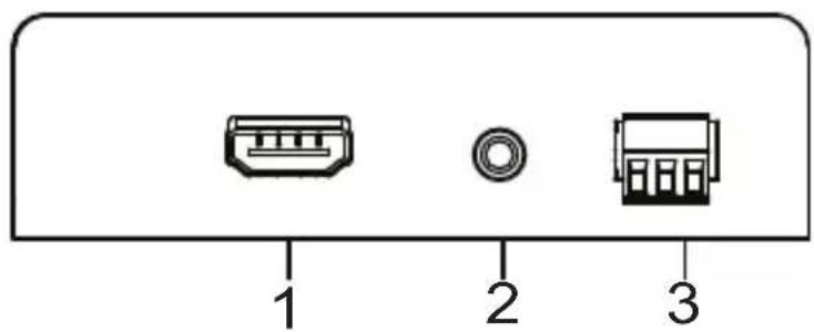
| 1 HDMI Input/Output Port | The cable from your HDMI source device plugs into the HDMI Input port (VE882T / VE892T).The cable from your HDMI display device plugs into this HDMI Output port (VE882R / VE892R). |
| 2 IR | Port Plug your IR Transmitter/Receiver here to transmit/receive signals to/from the IR remote control. |
| 3 RS-232 Port(Tx/Rx/Gnd) | Connect a computer or high-end system controller via this serial port. |
Rear View

| No. | Component Description |
| 1 | Optical In/Out Port* |
| 2 | Power Jack The power adapter cable plugs in here. |
*The Optical In/Out port's color varies as follows:
VE882T - Blue
VE882R - Yellow
VE892T - Purple
VE892R - White
Wall Mounting
For convenience and flexibility, the VE882 / VE892 can be mounted on the wall. To mount a unit do the following:
- Using the screws provided in the Mounting Kit, screw the mounting brackets onto the side panels of the unit as shown in the diagram below:

natural_image
Line drawing of an electronic device casing with ports and connectors (no text or symbols)Note: We recommend that you use M5 x 12 Phillips Type I cross, recessed type screws.
- Attach the bracket onto any convenient location on the wall.

natural_image
Line drawing of a rectangular electronic device with mounting holes and a handle (no text or symbols)Installation

- Make sure that the power to any device that you connect to the installation has been turned off. You must unplug the power cords of any computers that have the Keyboard Power On function.
- Make sure that all devices you will be installing are properly grounded.
- Do not look directly at the light coming from the fiber optic connectors and cable as it is harmful to the eyes.
Refer to the installation diagram on the next page (the numbers in the diagram correspond to the numbers of the steps) and do the following:
- Connect the HDMI input port on the VE882T/VE892T to the HDMI output port on your video source device using HDMI cable.
- Connect one end of the fiber optic cable (LC, single mode) to the Optical Out port on the VE882T/VE892T.
- Connect the other end of the fiber optic cable (LC, single mode) to the Optical In port on the VE882R/VE892R.
- Use an HDMI Cable to connect your video display to the HDMI output port on the VE882R/VE892R.
- Plug the power adapter cable into the power jack on the VE882/VE892.
- (Optional) Connect your computer or controller system (RS-232 Port) to the terminal block on the VE882/VE892 to perform serial commands.
- a. Connect an IR Transmitter/Receiver to the IR port on the VE882T/VE892T.
b. Connect an IR Transmitter/Receiver to the IR port on the VE882R/VE892R.
Note: The IR transmitter or IR receiver can be plugged into either the VE882T/VE892T or VE882R/VE892R unit depending on the device you want to control remotely.
VE882R/VE892R

flowchart
graph TD
    A["4 HDMI Display Device"] --> B["2"]
    B --> C["3"]
    C --> D["5"]
    D --> E["6 Serial Device"]
    A --> F["7b"]
    F --> G["VE882T/VE892T"]
    H["1 HDMI Source Device"] --> I["6 IR Port 7a"]
    I --> J["IR Port 7a"]
RS-232 Channel Transmission
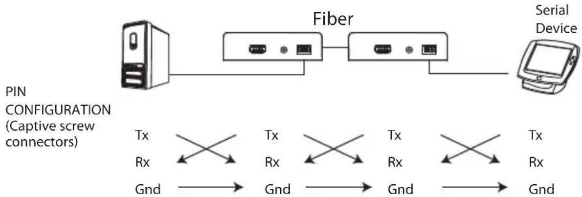
The RS-232 signal transmission flow is shown in the following illustration:
flowchart
graph LR
    A["Server"] --> B["Fiber"]
    B --> C["Serial Device"]
    D["PIN CONFIGURATION (Captive screw connectors)"] --> E["Tx Rx Gnd"]
    E --> F["Tx Rx Gnd"]
    F --> G["Tx Rx Gnd"]
    G --> H["Tx Rx Gnd"]
    H --> I["Tx Rx Gnd"]
From a source device, the RS-232 signal is transmitted (Tx) to the VE882T/VE892T receiving (Rx) unit; the VE882R/VE892R transmits (Tx) signals to the display device (Rx).
Specifications
| Function VE882T/VE892T VE882R/VE892R | |||
| Connectors HDMI In 1 x HDMI Type A | Female (Black) | N/A | |
Note: 1. The optical fiber modules are color-coded accordingly:
VE882T Blue
VE882R Yellow
VE892T Purple
VE892R White
- Operating distance is approximate. These are typical maximum distances that may vary depending on factors such as fiber type, fiber bandwidth, connector splicing, losses, modal or chromatic dispersion, environmental factors and kinks.
- It is recommended that you use a Single Mode fiber optic cable that conforms to the IEC 60793-2-50 B1.1 or ITU-T G.652.B specifications.
- The VE882 supports OM3 optical fiber which can extend the transmission distance up to 300 meters.
ATEN warrants its hardware in the country of purchase against flaws in materials and workmanship for a Warranty Period of two [2] years (warranty period may vary in certain regions/countries) commencing on the date of original purchase. This warranty period includes the LCD panel of ATEN LCD KVM switches. Select products are warranted for an additional year (see A+ Warranty for further details). Cables and accessories are not covered by the Standard Warranty.
What is covered by the Limited Hardware Warranty
ATEN will provide a repair service, without charge, during the Warranty Period. If a product is detective, ATEN will, at its discretion, have the option to (1) repair said product with new or repaired components, or (2) replace the entire product with an identical product or with a similar product which fulfills the same function as the defective product. Replaced products assume the warranty of the original product for the remaining period or a period of 90 days, whichever is longer. When the products or components are replaced, the replacing articles shall become customer property and the replaced articles shall become the property of ATEN.
To learn more about our warranty policies, please visit our website:
http://www.aten.com/global/en/legal/policies/warranty-policy/



Brand : ATEN
Model : VE892
Category : Audio/video extension