
VE829 - Audio/video extension ATEN - Free user manual and instructions
Find the device manual for free VE829 ATEN in PDF.


| Product Type | Audio/Video Extender |
| Model | VE829 |
| Brand | ATEN |
| Signal Type | VGA + Stereo Audio |
| Maximum Extension Distance | Up to 60 meters (200 ft) |
| Supported Resolutions | Up to 1920x1200 @ 60Hz |
| Audio Support | Unbalanced stereo (3.5mm jack) |
| Input Interface | 1x VGA (HDB-15), 1x Audio Mini Stereo |
| Output Interface | 1x VGA (HDB-15), 1x Audio Mini Stereo |
| Power Supply | External DC power adapter (5V/1A typical) |
| Power Consumption | Approx. 2.5W |
| Dimensions (L x W x H) | 126 x 80 x 25 mm |
| Weight | 0.2 kg (device only) |
| Operating Temperature | 0°C to 50°C (32°F to 122°F) |
| Storage Temperature | -20°C to 60°C (-4°F to 140°F) |
| Humidity | 0% to 80% RH, non-condensing |
| Housing Material | Metal |
| LED Indicators | Power, Signal Present |
| Compliance | CE, FCC |
| Package Contents | VE829 unit, power adapter, user manual |
Frequently Asked Questions - VE829 ATEN
User questions about VE829 ATEN
0 question about this device. Answer the ones you know or ask your own.
Ask a new question about this device
Download the instructions for your Audio/video extension in PDF format for free! Find your manual VE829 - ATEN and take your electronic device back in hand. On this page are published all the documents necessary for the use of your device. VE829 by ATEN.
USER MANUAL VE829 ATEN
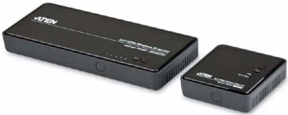
5x2 HDMI Wireless Extender VE829
User Manual
natural_image
Two ATEN wireless devices, one with a 5x2 HDMI Wireless Extender and the other with a network interface (no visible text or symbols on the devices themselves)RoHS
This product is RoHS compliant.
SJ/T 11364-2006
The following contains information that relates to China.
Be sure to register your product at our online support center:
International http://eservice.aten.com
Telephone Support
For telephone support, call this number:
| International 886-2-86 | 92-6959 |
| China 86-10-5255-01 | 10 |
| Japan 81-3-5615-581 | 1 |
| Korea 82-2-467-6789 | |
| North America 1-888- | 999-ATEN ext 4988 |
| United Kingdom 44-8 | 4481-58923 |
User Notice
All information, documentation, and specifications contained in this manual are subject to change without prior notification by the manufacturer. The manufacturer makes no representations or warranties, either expressed or implied, with respect to the contents hereof and specifically disclaims any warranties as to merchantability or fitness for any particular purpose. Any of the manufacturer's software described in this manual is sold or licensed as is. Should the programs prove defective following their purchase, the buyer (and not the manufacturer, its distributor, or its dealer), assumes the entire cost of all necessary servicing, repair and any incidental or consequential damages resulting from any defect in the software.
The manufacturer of this system is not responsible for any radio and/or TV interference caused by unauthorized modifications to this device. It is the responsibility of the user to correct such interference.
The manufacturer is not responsible for any damage incurred in the operation of this system if the correct operational voltage setting was not selected prior to operation. PLEASE VERIFY THAT THE VOLTAGE SETTING IS CORRECT BEFORE USE.
Package Contents
The VE829 package consists of:
◆ 1 VE829T 5x2 HDMI Wireless Extender
◆ 1 VE829R 5x2 HDMI Wireless Extender
◆ 2 IR Remote Control with batteries
◆ 1 Component Adapter Cable
◆ 1 IR Blaster Cable (Transmitter)
◆ 1 IR Sensor Extender Cable (Receiver)
◆ 1 HDMI cable
◆ 2 Power Adapter
◆ 1 User Instructions*
Check to make sure that all the components are present and that nothing got damaged in shipping. If you encounter a problem, contact your dealer.
Read this manual thoroughly and follow the installation and operation procedures carefully to prevent any damage to the unit, and/or any of the devices connected to it.
* Features may have been added to the VE829 since this manual was printed. Please visit our website to download the most up-to-date version.
© Copyright 2013 ATEN® International Co., Ltd.
Manual Date: 2013-10-02
ATEN and the ATEN logo are registered trademarks of ATEN International Co., Ltd. All rights reserved.
All other brand names and trademarks are the registered property of their respective owners.
Contents
User Information .... iii
Online Registration .... iii
Telephone Support ....iii
User Notice ....iii
Package Contents.... iv
About this Manual . . . . . . . . . . . . . . . . . . . . . . . . . . . . . . . . . . . . . . . . . . . . . . . . . . . . . . . . . . . . . . . . . vii
Conventions ...... viii
Product Information......viii
1. Introduction
Overview....1
Features 2
Requirements 3
Consoles 3
Sources 3
Cables 3
Components 4
VE829T Top View ....4
VE829R Top View 5
VE829R Rear View ....6
Front View 7
2. Hardware Setup
Wall Mounting 9
Single Station Installation 11
IR Blaster Extender Cable Setup 13
Transmitter.... 13
Receiver 13
3. Basic Operation
Overview....15
Transmitter and Receiver Link....15
Manual Switching 16
Front Panel Pushbutton....16
Remote Control....16
LED Display.... 17
Naming Source Devices 18
Device Pairing....18
Powering Off and Restarting.... 19
4. OSD Operation
Overview....21
Source Device Switching 21
Adding and Selecting Active Transmitter 21
Remove Transmitter 23
Modify Transmitter Name 23
Appendix
Safety Instructions 25
Technical Support. 27
International 27
North America. 27
Specifications 28
Video and Audio Format Supported 29
Troubleshooting 30
Limited Warranty....32
About this Manual
This User Manual is provided to help you get the most from your system. It covers all aspects of installation, configuration and operation. An overview of the information found in the manual is provided below.
Chapter 1, Introduction, introduces you to the VE829 system. Its purpose, features and benefits are presented, and its front and back panel components are described.
Chapter 2, Hardware Setup, describes how to set up your installation. Diagrams showing the necessary steps are provided.
Chapter 3, Basic Operation, explains the fundamental concepts involved in operating the VE829.
Chapter 4, OSD Operation, provides a complete description of the VE829's On-Screen Display (OSD), and how to work with it.
An Appendix, provides specifications and other technical information regarding the VE829.
Conventions
This manual uses the following conventions:
Monospaced Indicates text that you should key in.
[ ] Indicates keys you should press. For example, [Enter] means to press the Enter key. If keys need to be chorded, they appear together in the same bracket with a plus sign between them: [Ctrl+Alt].
- Numbered lists represent procedures with sequential steps.
◆ Bullet lists provide information, but do not involve sequential steps.
→ Indicates selecting the option (on a menu or dialog box, for example), that comes next. For example, Start → Run means to open the Start menu, and then select Run.

Indicates critical information.
Product Information
For information about all ATEN products and how they can help you connect without limits, visit ATEN on the Web or contact an ATEN Authorized Reseller. Visit ATEN on the Web for a list of locations and telephone numbers:
| International http://www.aten.com |
| North America http://www.aten-usa.com |
Overview
The VE829 5x2 HDMI Wireless Extender is the first of its kind to send full uncompressed HD 1080p, while connecting up to 5 source devices and allowing users to switch and independently select any source to display on two HDTVs. Its wireless matrix feature is the biggest breakthrough in Audio / Video solutions to date. This means you can watch cable TV in one location (transmitter side) and, at the same time, independently select a Blu-ray movie to watch in another location (receiver side). The VE829 is capable of streaming Full HD 1080p with support for 3D content and digital audio up to 30m away, within the home or any desired setup.
Note: Distance, quality and signal may vary depending on the environment; solid structures, such as steel, concrete and brick may result to shorter distance coverage or complete loss of signal.
The solution consists of a Wireless Transmitter and a Wireless Receiver with connections for the HDMI and Component, along with a loop through (local port) for advanced two-HDTV setups. It also features USB HID connectivity for adding a computer / laptop to the installment, giving you wireless control from the VE829R. Infrared (IR) pass-through enables wireless control of your source devices and helps consolidate your HD A/V electronics, such as a DVDs / Blu-ray players, DVRs / Cable boxes, Game consoles and computers allowing you to design your own custom entertainment space.
Features
- Wireless transmission of fully uncompressed HD videos up to 30m for two HDTVs
Note: Distance, quality and signal may vary depending on the environment; solid structures, such as steel, concrete and brick may result to shorter distance coverage or complete loss of signal.
- Allows you to switch and independently select any of 5 sources (4 x HDMI connectors, 1 x component connector) between 2 HDTVs
- Supports full uncompressed HD, 1080P, 3D content, and 5.1 channel digital audio
♦ Superior video quality – 480P, 720P, 1080i, 1080P - USB HID ports on Transmitter and Receiver units enable wireless keyboard connectivity to control attached computers/laptops
- Based on WHDI™ technology – Low latency < 1 ms
♦ HDMI (3D), HDCP compatible - No software or driver installation needed
Requirements
Consoles
◆ 2 HDMI displays with HDMI Type A output connectors
♦ Keyboard / mouse (optional, USB HID function)
Sources
◆ Up to 4 video source devices with an HDMI Type A input connector
◆ 1 video source with component output connector
◆ Computer or laptop (optional)
Cables
◆ Up to 4 HDMI cables for the source devices you will be connecting
Note: The package includes 1 HDMI cable.
◆ 2 HDMI cables for the display devices you will be using
◆ 1 Component adapter cable
◆ 1 Component cable (not included with this package)
◆ 1 IR Blaster Cable (optional)
◆ 1 IR Sensor Extender Cable (optional)
◆ 1 mini USB to Type A USB cable (optional)
Components
VE829T Top View

| No. | Component Description |
| 1 Source LEDs These | LEDs light green to indicate active connection to a source.◆ The LEDs blink to indicate that it is trying to link with a Receiver.◆ The LEDs blink quickly when no source is detected.◆ The LEDs blink slowly if the video from the source cannot be recognized. |
| 2 Source Selection Button | Press this to manually switch between ports. |
| 3 Power Button / LED | Press this button to power on/off the VE829T.Note: The HDMI Out on the Transmitter is always ON even when the Transmitter is in standby mode.◆ The LED lights green to indicate that the device is receiving power.◆ The LED turns red when the device is in standby mode.◆ The LED blink to indicate that it is trying to link with a Receiver. |
VE829R Top View

| No. | Component Description | |
| 1 | Power Button / LED | Press this button to power on/off the VE829R.Note: The HDMI Out on the Transmitter is always ON even when the Receiver is in standby mode.The LED lights green to indicate that the device is receiving power.The LED turns red when the device is in standby mode.The LED blinks to indicate that it is trying to link with a Transmitter. |
| 2 | Source Button Press | this to manually switch between ports. |
| 3 | Video LED The LED | blinks to indicate that the VE829R does not detect an input source and/or the video format is not recognized.The lights green when the video from the input source is recognized. |
| 4 | Wireless Signal LED | The LED blinks to indicate that it is trying to link with the Transmitter, and lights green when the connection is established. |
VE829T Rear View

| No. | Component Description | |
| 1 | Power Adapter DC IN | Plug one end of the power adapter cable into this power jack, and the other end into an appropriate DC power source. |
| 2 | IR Out for IR Blaster | Connect IR Blaster Cable to port to deliver signals from the IR remote controls of your input source devices.Refer to IR Blaster Extender Cable Setup, page 13 for details on how to set up the IR Blaster Cable for your source devices. |
| 3 | Component IN (Optional) | Use an adapter cable to connect your component input source device to this port. |
| 4 | HDMI IN Use an HDMI | cable to connect your HDMI input source device to any of these ports (1~4). You can connect up to 4 HDMI input source devices. |
| 5 | HDMI OUT Use an HDMI | cable to connect your HDMI display device to this port. |
| 6 | Mini USB Port Connect | a computer to this port using a mini USB to Type A USB cable. |
VE829R Rear View
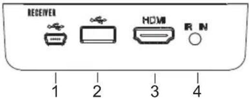
| No. | Component Description | |
| 1 | Power Adapter DC IN | Use the provided mini USB power adapter and connect his port to a power outlet. |
| 2 | USB HID Connect a USB | keyboard / mouse to this port to control the computer connected to the Transmitter. The VE829 supports USB HID function for keyboard / mouse usage. |
| 3 | HDMI OUT Use an HDMI | cable to connect your HDMI display device to this port. |
| 4 | IR In for IR Sensor Extender | Connect the IR Sensor Extender to this port to receive signals from the IR remote controls of your input source devices. Refer to IR Blaster Extender Cable Setup, page 13 for details. |
Front View
VE829T

natural_image
Simple line drawing of a rectangular shape with a circular top and a vertical line marked '1' (no text or symbols)VE829R

natural_image
Simple diagram of a rectangular shape with a circle at the top and a vertical line labeled '1' pointing downward (no text or symbols beyond the number)| No. | Component Description |
| 1 IR | Receiver This receives signals from the IR remote control. |
IR Remote Control
| No. | Component Description |
| 1 Power On Press | this button to power on the Transmitter and Receiver.Note:If both Transmitter and Receiver Power LEDs are red, press Power ON while pointing to the Receiver to wake up both units automatically. |
| 2 Power Off Press | this button to turn the Transmitter and Receiver OFF. |
3 Info Press this button to haveTransmitter or Receiver display the signal quality, source, channel and resolution, as follows: HDMI1 CH1 1280x1024Press it again to exit the Info display. HDMI1 CH1 1280x1024Press it again to exit the Info display. | |
| 4 IR Button Press this button to change the IR Receiver's frequency according to the input source device's requirement.Frequency ranges from 47KHz to 56KHz to 38KHz. | |
| 5 Source Press this button to select the audio/video source inputs, then press OK. | |
| 6 Transmitter No. | Press to button to switch to another transmitter (if more than one Transmitter is within range). |
| 7 Up / Down Press | this button to select the audio/video input source (for the transmitter unit), then press OK. |
| 8 Left / Right Press | to select the audio/video input source (for the receiver unit), then press OK. |

Note: 1. The battery compartment is located at the back panel of the IR remote control.
- Refer to Chapter 4 for further details on how to use the IR remote control to operate your VE829 installation.
Chapter 2
Hardware Setup

-
Important safety information regarding the placement of this device is provided on page 25. Please review it before proceeding.
-
Make sure that the power to all devices connected to the installation is turned off. You must unplug the power cords of any computers that have the Keyboard Power On function.
Wall Mounting
For convenience and flexibility, the VE829R can be mounted on the wall. To mount a unit do the following:
- Use the sheet of paper provided with this package, which illustrates the position of the main holes. Place this paper against the wall and drill two 1/4" holes as per instructions:

- Insert anchors into the wall, followed by the screws. Leave 5/8" of the screw protruding for mounting the Receiver:

natural_image
Four identical line-drawn cylindrical objects with circular ends, arranged in a row (no text or symbols)- Hang the VE829R by having the bottom panel holes aligned into the screws. Slide down into position.
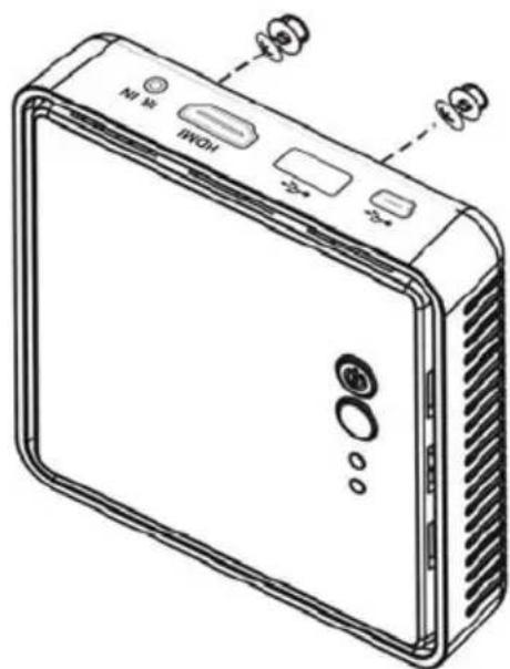
Note: These screws are not provided. We recommend that you use M5 x 12 Phillips Type I cross, recessed type screws.
Single Station Installation
Note: Make sure that the power to any device that you connect to the installation has been turned off. You must unplug the power cords of any computers that have the Keyboard Power On function.
To set up your VE829 installation, refer to the installation diagram on the next page (the numbers in the diagrams correspond to the steps below), and do the following:
- Use HDMI cables to connect the HDMI output ports on up to 4 source device(s) to the HDMI IN (1-4) ports on the VE829T.
- Use the provided component adapter cable to connect the component source device to the YPbPr input port on the VE829T.
- a. Use an HDMI cable to connect the HDMI input port on the video display device to the HDMI OUT port on the rear of the VE829T. b. Use an HDMI cable to connect the HDMI input port on the video display device to the HDMI OUT port on the rear of the VE829R.
- (Optional) Connect a PC to the USB port using a mini USB to Type A USB cable.
- a. Connect one end of the IR Blaster Cable to the IR Out port on the VE829T, and attach the IR Blaster “heads” to the video source devices for IR remote control operation on the Receiver side.
Note: Refer to the User Manual for instructions on how to attach the IR Blaster heads to your source devices.
b. Connect the IR Sensor Extender Cable to the IR In port on the VE829R, and attach the IR sensor to a visible area for IR remote control operation.
- Power on the VE829T / VE829R:
a. Plug the provided power adapter into an appropriate DC power source; plug the power adapter cable into the Power Jack on the VE829T.
b. Plug the provided power adapter into an appropriate DC power source; plug the power adapter cable into the Mini USB port on the VE829R.
Note: If both Transmitter and Receiver Power LEDs are red (standby mode), press the POWER button on the Receiver to wake up both units automatically.
- (Optional) For USB HID control (keyboard / mouse) of the PC connected to the Transmitter, connect a keyboard or mouse to the USB port.
- Power on all connected source devices.

IR Blaster Extender Cable Setup
To use the remote controls for your input source devices (i.e., DVD player, game console, Set-top box, etc.) from the Receiver side, use the provided IR Blaster Extender Cable and IR Sensor Extender Cable. This setup conveniently enables a user to control the input source devices even while physically located up to 100 feet away them. Do the following steps for your units:
Transmitter
- Connect one end of the IR Blaster Extender Cable to the IR Out port on the VE829T.
- Attach the IR Blaster heads to the input source device panels – specifically, over the IR sensor of the audio/video device.
Receiver
- Connect one end of the IR Sensor Extender Cable to the IR In port on the VE829R.
- Attach the IR sensor to a visible area where you can point your IR remote control (i.e. front panel of the display device or against a wall).

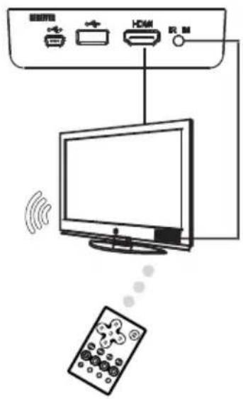
Note: The VE829 IR sensors support 38 KHz, 47 KHz and 56 KHz remote signal protocol.
This Page Intentionally Left Blank
Overview
The VE829 Transmitter and Receiver communicate wirelessly. At startup, ensure that the units first establish a connection with each other.
See Transmitter and Receiver Link below for details.
There are various convenient methods to operate the VE829: manually via the panel pushbutton, using the IR remote control, and via the On-Screen Display (OSD). Manual operation involves pressing the Source pushbutton located on the unit's top panel or using the Source button on the remote control.
Input source switching, as well as adding/removing Transmitters and modifying the Transmitter name, via OSD using the remote control are discussed in Chapter 4.
Transmitter and Receiver Link
After powering on the Transmitter and Receiver, the panel LEDs blink to indicate that the two units are establishing a connection. This takes around 15 to 20 seconds. The LEDs light a steady green when the boot up is completed and the VE829 devices are ready for use.
Note: 1. If the LEDs continue to blink after 80 seconds, check the distance between the Transmitter and Receiver. The maximum distance between VE829T / VE829R is 100 feet, while the minimum distance between VE829 devices is 6.5 feet if you have more than one set of VE829.
2. Distance, quality and signal may vary depending on the environment; solid structures, such as steel, concrete and brick may result to shorter distance coverage or complete loss of signal.
Make sure your display device is set in HDMI input mode. Refer the user manual of your HDMI display for more information.
Manual Switching
You can manually switch input sources by pressing the pushbutton on the top panel of the VE829T / VE829R, or using the IR remote control.
Front Panel Pushbutton
Press the SOURCE button on the top panel of the Transmitter or Receiver to toggle between connected input sources, and select the video you want displayed on screen.
Remote Control
Press the SOURCE button on your IR remote control while pointing at the Transmitter or Receiver to toggle between connected input sources, and select the video you want displayed on screen.
Note: 1. The default input source is the device connected to the HDMI 1 port.
- You can also switch between source inputs via the OSD using the provided remote control. Refer to Source Device Switching, page 21 for instructions on how to use the remote control, as well as the On-Screen Display (OSD).
LED Display
The Mode and Port Selection Pushbuttons on the VE829's front panel each have three corresponding LED icons that represent audio, KVM, and USB Link. These light green or orange, depending on status, as shown in the table, below:
| Item / Mode | Status Description | Power LED | Source LED | Video LED (VE829R) | Wireless LED (VE829R) | OSD Display |
| Standby For | power saving mode. | Static Red | off off off |  | ||
| Initial Boot up / Warm up | It will spend 15 ~ 20 seconds for system boot up. | Blinking Green | Blinking B | Blinking Blinking |  | |
| Searching available channels | Continuing search available channels If system can't establish link over 80s after initialization. | Blinking Green | Blinking B | Blinking Blinking |  | |
| Wireless linked Mode | No input from selected source (Note B) | Static Green | Blinking (Quickly) | Blinking Static Green | 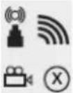 | |
| Video format not recognized (Note C) | Static Green | Blinking (Slowly) | Blinking Static Green |  | ||
| Video format is recognized | Static Green | Static Green | Static Green | Static Green | - |
Note: 1. Make sure the source device has been powered on and that the signal output is set to HDMI.
- If there is no video displayed and OSD shows “Not Supported Format”, the video resolution or frame rate from the source device is not supported. Refer to page 29 for a list of supported video timing formats.
Naming Source Devices
You can give names the input source devices attached to the VE829T (Transmitter) to easily identify them. To do this, follow these steps:
- Press and hold the Source button on the top panel of the VE829T for over 3 seconds.
- In the screen that appears on your HDMI display, input the name you want to give the input source device. Do this pointing the remote control at the VE829T and using the Up and Down keys to change the letters / numbers; use the Left and Right keys to move the cursor. The IR key serves as a backspace.
- Save the input source device name by either pressing the Source key on the remote control or on the top panel of the VE829T.
The name should appear on screen when the input source device is selected for both Transmitter and Receiver sides.
Note: Refer to Modify Transmitter Name, page 23 for steps on using the Transmitter No. button to change the Transmitter name.
Device Pairing
If you want to link another VE829T (Transmitter) with an existing VE829R (Receiver), do the following steps:
- Enter the Pairing mode for the VE829T. Power off the unit by unplugging it.
- Press and hold down the Power button. Plug the unit but keep pressing the Power button until the LED is blinking orange indicating that the VE829T has entered the Pairing mode.
- Do the same steps for the VE829R. Once the receiver enters the Pairing mode, the screen shows a progress bar.
- Once the pairing is finished, both units reboot and are ready to work together.
Powering Off and Restarting
If it becomes necessary to power off the unit, before starting it back up you must do the following:
- Shut down all the devices that are attached to the VE829T / VE829R.
- Unplug the VE829T / VE829R's power adapter cable.
- Wait 10 seconds, then plug the VE829T / VE829R's power adapter cable back in.
- After the VE829T / VE829R is up, Power on the attached devices.
This Page Intentionally Left Blank
Overview
The On-Screen Display (OSD) is a menu driven method to handle VE829T / VE829R control and switching operations. It appears on the attached HDMI displays (Transmitter or Receiver) after hardware connections are made and the devices are powered on.
Source Device Switching
You can switch between source inputs via the OSD using the IR remote control as follows:
- VE829T (Transmitter): Press the Up / Down keys.
- VE829R (Receiver): Press the Left / Right keys.

The OSD cycles through the input devices and you can press OK once the desired source is selected.
Adding and Selecting Active Transmitter
You can add up to 4 VE829T (Transmitter) unit to a VE829R (Receiver) via the OSD. If more than one Transmitter is within range and/or are added with the Receiver, you can use the OSD to select which one to use for the session.
The original transmitter paired with your Receiver is named Transmitter 1, while the transmitter to be added is named Transmitter 2 in this section.
To add another Transmitter to a Receiver, do the following steps:
- Make sure Transmitter 1 is powered off. Press Transmitter No. on the IR remote control (pointing to the Receiver).
- Press the Up / Down button on your remote control and go to SETUP, press OK.
- Select Add New Transmitter. The VE829R starts searching for Transmitters within range.
Note: Press Transmitter No. key to exit the Searching screen.
During this period, press and hold the Power pushbutton on the top panel of the Transmitter you want to add, then power it on. Hold the power button down until the Power LED on the Transmitter starts to blink (orange), which indicates that the unit has entered Connecting Mode. Once the process is successful, the OSD displays Transmitter 2 on screen.
Note: Refer to Naming Source Devices, page 18 for details on how to edit the name of a Transmitter.
- After successfully connecting the Receiver with Transmitter 2, you can now power on Transmitter 1. The Receiver can be linked with either transmitters (1 and 2), which can be selected through the Transmitter No. button on the remote control.
Note: 1. To add more transmitters, repeat steps 1 to 4.
- Although you can connect the Receiver with multiple Transmitters, only one Receiver can operate at a time.
- If you have more than one pair of this product, each Transmitter and Receiver should be at least 6.5 feet away from one another.
- When Receiver 1 is connected to Transmitter 2, the original receiver paired with Transmitter 2 (Receiver 2) gets disconnected. You need to pair Transmitter 2 to Receiver 2 again to use them together. See Device Pairing, page 18 for details.
Remove Transmitter
To remove a Transmitter from the list of transmitters paired with a receiver, do the following:
- Press Transmitter No. on the IR remote control, go to SETUP then press OK.
- Select Remove Transmitter.
- Go to the Transmitter you want to remove and press OK.
Modify Transmitter Name
To change a Transmitter name, do the following:
- Press Transmitter No. on the IR remote control, go to SETUP then press OK.
- Select Modify Transmitter Name.
- Go to the Transmitter that you want to rename.
- Using the IR remote control, press the Up and Down keys to change the letters / numbers; use the Left and Right keys to move the cursor. The IR key serves as a backspace.
Note: Refer to Naming Source Devices, page 18 for steps on using the Source button on the top panel of the VE829T to change the Transmitter name.
This Page Intentionally Left Blank
Safety Instructions
- Read all of these instructions. Save them for future reference.
◆ Follow all warnings and instructions marked on the device. - This product is for indoor use only.
- Do not place the device on any unstable surface (cart, stand, table, etc.). If the device falls, serious damage will result.
♦ Do not use the device near water. - Do not place the device near, or over, radiators or heat registers.
- The device cabinet is provided with slots and openings to allow for adequate ventilation. To ensure reliable operation, and to protect against overheating, these openings must never be blocked or covered.
- The device should never be placed on a soft surface (bed, sofa, rug, etc.) as this will block its ventilation openings. Likewise, the device should not be placed in a built-in enclosure unless adequate ventilation has been provided.
- Never spill liquid of any kind on the device.
- Unplug the device from the wall outlet before cleaning. Do not use liquid or aerosol cleaners. Use a damp cloth for cleaning.
- The device should be operated from the type of power source indicated on the marking label. If you are not sure of the type of power available, consult your dealer or local power company.
- The device is designed for IT power distribution systems with 230V phase-to-phase voltage.
- To prevent damage to your installation, it is important that all devices are properly grounded.
- The device is equipped with a 3-wire grounding type plug. This is a safety feature. If you are unable to insert the plug into the outlet, contact your electrician to replace your obsolete outlet. Do not attempt to defeat the purpose of the grounding-type plug. Always follow your local/national wiring codes.
- Do not allow anything to rest on the power cord or cables. Route the power cord and cables so that they cannot be stepped on or tripped over.
If an extension cord is used with this device make sure that the total of the ampere ratings of all products used on this cord does not exceed the extension cord ampere rating. Make sure that the total of all products plugged into the wall outlet does not exceed 15 amperes.
- To help protect your system from sudden, transient increases and decreases in electrical power, use a surge suppressor, line conditioner, or un-interruptible power supply (UPS).
- Position system cables and power cables carefully; Be sure that nothing rests on any cables.
- Never push objects of any kind into or through cabinet slots. They may touch dangerous voltage points or short out parts resulting in a risk of fire or electrical shock.
- Do not attempt to service the device yourself. Refer all servicing to qualified service personnel.
- If the following conditions occur, unplug the device from the wall outlet and bring it to qualified service personnel for repair.
- The power cord or plug has become damaged or frayed.
- Liquid has been spilled into the device.
- The device has been exposed to rain or water.
- The device has been dropped, or the cabinet has been damaged.
- The device exhibits a distinct change in performance, indicating a need for service.
- The device does not operate normally when the operating instructions are followed.
- Only adjust those controls that are covered in the operating instructions. Improper adjustment of other controls may result in damage that will require extensive work by a qualified technician to repair.
Technical Support
International
- For online technical support – including troubleshooting, documentation, and software updates: http://eservice.aten.com
- For telephone support, Telephone Support, page iii.
North America
| Email Support support@aten-usa.com | ||
| Online Technical Support | Troubleshooting Documentation Software Updates | http://www.aten-usa.com/support |
| Telephone Support 1-888-999-ATEN | ext 4988 | |
When you contact us, please have the following information ready beforehand:
◆ Product model number, serial number, and date of purchase.
- Your computer configuration, including operating system, revision level, expansion cards, and software.
◆ Any error messages displayed at the time the error occurred.
◆ The sequence of operations that led up to the error.
◆ Any other information you feel may be of help.
Specifications
| Function VE829T VE829R | ||||
| Connectors Input HDMI In 4 x HDMI Type AFemale (Black) | N/A | |||
| N/A | ||||
| N/A | ||||
| HID for Keyboard/Mouse) (Black) | ||||
| (Black) | ||||
| 1 x HDMI type AFemale (Black) | ||||
| N/A | ||||
| N/A | ||||
| Wireless 5Ghz | ||||
| USB) | ||||
| Switches | Power | 1 x Pushbutton | 1 x Pushbutton | |
| Source | 1 x Pushbutton | 1 x Pushbutton | ||
| LEDs | Source | 5 (Green) | N/A | |
| Video Source | N/A | 1 (Green) | ||
| Wireless Signal | N/A | 1 (Green) | ||
| Resolution | HDMI input | 480p, 720p, 1080i and 1080p | ||
| Component input | 480i, 480p, 576i, 576p, 720p, 1080i and 1080p | |||
| Audio | 5.1 channel digital audio | |||
| Transmission Distance | Up to 30m | |||
| Power Consumption | DC5V, 9.5W | DC5V, 6.7W (mini USB) | ||
| Environment | Operating Temp. | 0-40°C | ||
| Storage Temp. | -20-60°C | |||
| Humidity | 0-80% RH, Non-condensing | |||
| Physical Properties | Housing | Plastic | ||
| Weight | 280 g | 130 g | ||
| Dimensions(L x W x H) | 23.40 x 9.65 x 3.25 cm | 9.50 x 9.50 x 3.55 cm | ||
Video and Audio Format Supported
| 2D Video Format Timings Resolution | |
| Primary CEA Video Timing | |
| 640x480p @ 59.94 / 60Hz 480p | |
| 720x480p @ 59.94Hz | |
| 720x480p @ 60Hz | |
| 720x576p @ 50Hz 576p | |
| 1280x720p @ 50Hz 720p | |
| 1280x720p @ 59.94 / 60Hz | |
| 1920x1080i @ 50Hz 1080i | |
| 1920x1080i @ 59.94 / 60Hz | |
| 1920x1080p @ 50Hz 1080p / 60 | |
| 1920x1080p @ 59.94 / 60Hz | |
| Secondary CEA Video Training | |
| 1920x1080p @ 23.98 / 24Hz 1080p / 24 | |
| 1920x1080p @ 25Hz | |
| 1920x1080p @ 29.97 / 30Hz | |
| VESA Timing (DVI Only) | |
| 640x480 @ 59.94 / 72.809Hz VGA | |
| 800x600 @ 60.317 / 72.188Hz SVGA | |
| 1024x768 @ 60 / 70.069Hz XGA | |
| 1280x768 @ 60 Hz WXGA | |
| 1280x1024 @ 60 Hz SXGA | |
| Mandatory CEA 3D Video Format Timings | |
| 1280x720p @ 50Hz Top-and-Bottom | |
| 1280x720p @ 50Hz Frame packing | |
| 1280x720p @ 59.94 / 60Hz Top-and-Bottom | |
| 1280x720p @ 59.94 / 60Hz Frame packing | |
| 1920x1080i @ 50Hz Side-by-Side (Half) | |
| 1920x1080i @ 59.94 / 60Hz Side-by-Side (Half) | |
| 1920x1080p @ 23.98 / 24Hz Top-and-Bottom | |
| 1920x1080p @ 23.98 / 24Hz Frame packing | |
| Audio Bit Rate Support | |||
| 2 Channel PCM Supported Sampling Rate | |||
| 16 bits 32 KHz | 44.1 KHz | 48 KHz | 96 KHz |
| 24 bits 32 KHz | 44.1 KHz | 48 KHz | 96 KHz |
Troubleshooting
Operation problems can be due to a variety of causes. The first step in solving them is to make sure that all cables are securely attached and seated completely in their sockets.
| Problem Resolution | |
| The Power LED does not light up. | Check that the power adapters of the Transmitter / Receiver are properly plugged into a functioning power outlet. |
| No video shows on the HDMI display. | ◆ Check that the cables from the input source devices to the Transmitter are correct and properly attached.◆ Ensure that the display is set to receive HDMI signals.◆ Verify the status ofPowerLED, as follows:◆PowerLED blinking (green):– Check that the distance between the Transmitter and Receiver does not exceed 100 feet.– Move the Transmitter closer to the Receiver.◆PowerLED lights solid + Source LED blinking slowly (green)– Ensure that the video resolution and frame rate selected are supported. SeeVideo and Audio Format Supported, page 29 for more details.– Connect the source device to your display to check the video format compatibility.– Check if the video resolution on your HDMI display is set to 1080p, 1080i, 720p, 576p, or 480p resolution. Refer toVideo and Audio Format Supported, page 29.◆PowerLED lights solid + Source LED blinking quickly (green)– Check that the cables from the input source devices to the Transmitter are correct and properly attached.– Ensure your input source devices are powered on.– Check that proper cable is connected between the Receiver and the HMDI display device. |
| Poor picture quality or intermittent video | ◆ Check if the video resolution on your HDMI display is set to 1080p, 1080i, 720p, 576p, or 480p resolution. Refer to Video and Audio Format Supported, page 29.◆ Check that the distance between the Transmitter and Receiver does not exceed 100 feet.◆ Solid structures (walls, panels, beams) between the Transmitter and Receiver can affect signal quality. Consider installing the units with the least amount of barriers between them. |
| No audio | ◆ Check your display's volume is not set to Mute.◆ Check your input source device's audio volume has been enabled. Adjust the volume accordingly.◆ Ensure the bit rate of audio from the source device is supported (refer to page 29). |
| IR Remote Control cannot control input source device. | ◆ Check where is IR sensor is located on the input source device. Make sure that the IR Blaster Extender Sensor is close aligned to the input source device's IR sensor.◆ Change the IR Blaster Extender frequency to meet the input source device's requirement. See IR Blaster Extender Cable Setup, page 13. |
| No 3D video output | ◆ Check that the connected HDMI displays on the Transmitter and Receiver can support 3D video format.◆ Turn off 2D HDTV mode on your HDMI display (that supports 3D video format) and reboot the display. Set the input source device to 3D video format output for the 3D display.◆ Check the video output setting of the input source device (ex. Blu-ray Disc, PS3..etc.) supports 3D video format.◆ Ensure the 3D format timing from the input source device is supported (refer to page 29). |
Limited Warranty
IN NO EVENT SHALL THE DIRECT VENDOR'S LIABILITY EXCEED THE PRICE PAID FOR THE PRODUCT FROM DIRECT, INDIRECT, SPECIAL, INCIDENTAL, OR CONSEQUENTIAL DAMAGES RESULTING FROM THE USE OF THE PRODUCT, DISK, OR ITS DOCUMENTATION.
The direct vendor makes no warranty or representation, expressed, implied, or statutory with respect to the contents or use of this documentation, and especially disclaims its quality, performance, merchantability, or fitness for any particular purpose.
The direct vendor also reserves the right to revise or update the device or documentation without obligation to notify any individual or entity of such revisions, or update. For further inquiries, please contact your direct vendor.
Contents
User Information .... iii
Online Registration .... iii
Telephone Support ....iii
User Notice ....iii
Package Contents.... iv
About this Manual . . . . . . . . . . . . . . . . . . . . . . . . . . . . . . . . . . . . . . . . . . . . . . . . . . . . . . . . . . . . . . . . . . . . . . . vii
Conventions ...... viii
Product Information......viii
1. Introduction
Overview....1
Features 2
Requirements 3
Consoles 3
Sources 3
Cables 3
Components 4
VE829T Top View ....4
VE829R Top View 5
VE829R Rear View ....6
Front View 7
2. Hardware Setup
Wall Mounting 9
Single Station Installation 11
IR Blaster Extender Cable Setup 13
Transmitter.... 13
Receiver 13
3. Basic Operation
Overview....15
Transmitter and Receiver Link....15
Manual Switching 16
Front Panel Pushbutton....16
Remote Control....16
LED Display.... 17
Naming Source Devices 18
Device Pairing....18
Powering Off and Restarting.... 19
4. OSD Operation
Overview....21
Source Device Switching 21
Adding and Selecting Active Transmitter 21
Remove Transmitter 23
Modify Transmitter Name 23
Appendix
Safety Instructions 25
Technical Support. 27
International 27
North America. 27
Specifications 28
Video and Audio Format Supported 29
Troubleshooting 30
Limited Warranty....32



- 5x2 HDMI Wireless Extender VE829
- RoHS
- SJ/T 11364-2006
- Telephone Support
- User Notice
- Package Contents
- Contents
- Introduction
- Hardware Setup
- Basic Operation
- OSD Operation
- Appendix
- About this Manual
- Conventions
- Product Information
- Overview
- Features
- Requirements
- Consoles
- Sources
- Cables
- Components
- Front View
- Chapter 2
- Hardware Setup
- Wall Mounting
- Single Station Installation
- IR Blaster Extender Cable Setup
- Transmitter
- Receiver
- Transmitter and Receiver Link
- Manual Switching
- Front Panel Pushbutton
- Remote Control
- LED Display
- Naming Source Devices
- Device Pairing
- Powering Off and Restarting
- Source Device Switching
- Adding and Selecting Active Transmitter
- Remove Transmitter
- Modify Transmitter Name
- Safety Instructions
- Technical Support
- International
- Troubleshooting
- Limited Warranty
Brand : ATEN
Model : VE829
Category : Audio/video extension