
UT325 - Environment thermometer Uni-T - Free user manual and instructions
Find the device manual for free UT325 Uni-T in PDF.


| Type of product | Environment thermometer |
| Brand | Uni-T |
| Model | UT325 |
| Display | LCD with backlight |
| Measurement range (K-type) | -50°C to 1300°C (-58°F to 2372°F) |
| Accuracy | ±1.5% of reading or ±1°C (whichever greater) |
| Resolution | 0.1°C / 0.1°F |
| Number of channels | 2 (dual-channel) |
| Probe type | K-type thermocouple (included) |
| Functions | Data hold, max/min recording, auto power off, °C/°F switch |
| Power supply | 9V battery (6F22 or equivalent) |
| Battery life | Approximately 200 hours |
| Dimensions | 180 x 72 x 32 mm |
| Weight | 200 g (including battery) |
| Operating temperature | 0°C to 50°C (32°F to 122°F) |
| Storage temperature | -20°C to 60°C (-4°F to 140°F) |
| Cleaning | Wipe with a soft dry cloth; do not use solvents |
| Safety precautions | Do not measure live circuits; use only K-type probes within rated temperature |
| Accessories included | 2x K-type thermocouple probes, 9V battery, user manual |
| Repairability | User replaceable battery; probes can be replaced |
Frequently Asked Questions - UT325 Uni-T
User questions about UT325 Uni-T
0 question about this device. Answer the ones you know or ask your own.
Ask a new question about this device
Download the instructions for your Environment thermometer in PDF format for free! Find your manual UT325 - Uni-T and take your electronic device back in hand. On this page are published all the documents necessary for the use of your device. UT325 by Uni-T.
USER MANUAL UT325 Uni-T
Digital Thermometers
Overview
The Uni-Trend Model UT321, UT322, UT323 and UT325 Thermometers (the thermometer) are microprocessor-based, digital thermometers designed to use external J-, K-, T-, E-, R-, S- and N-type thermocouples (temperature probes) as temperature sensors.
- UT321: single input(T1), suitable for K-, J-, T- and E- type thermocouples
- UT322: dual input(T1,T2), suitable for K-, J-, T- and E-type thermocouples
- U1323: single input[11], suitable for K-, J-, T-, E-, R-, S- and N-type thermocouples. Equipped with over-limit alarm, over-limit signal output and user self-debug
Equipped with over-limit alarm, over-limit signal output and user con developing features. - UT325: dual input(T1,T2), suitable for K-, J-, T-, E-, R-, S- and N-type thermocoupling
Thermocouples. Equipped with over-limit alarm, over-limit signal output and user self debris features
Safety Information
Use the thermometer only as specified in this manual. Otherwise, the protection provided by the meter may be impaired.
Refer to safety information in Table 1 and the international symbols in Table 2.
Table 1. Safety Information
Warning
A warning identified conditions and actions that pose hazards to the user. To avoid electrical shock or personal injury, follow these guidelines:
- Before using the thermometer inspect the case. Do not use the thermometer if it appears damaged. Look for cracks or missing plastic. Pay particular attention to the insulation around the connectors.
- Disconnect the thermocouple(s) from the thermometer before opening the case.
- Replace the batteries as soon as the battery indicator (☐) appears. The possibility of false readings can lead to personal injury.
- Do not use the thermometer if it operates abnormally. Protection may be
impaired. When in doubt, have the thermometer serviced.
- Do not operate the thermometer around explosive gas, vapor, or dust.
- Do not apply more than the rated voltage, as marked on the thermometer (300.0
- DO not apply more than the failed voltage, as marked on the thermometer (30V) between the thermocouple(s), or between any thermocouple and earth ground.
- When potential differences are anticipated between the thermocouples, use
electrically insulated thermocouples.
- When servicing the thermometer, use only specified replacement parts.
Caution
A caution Identifies conditions and actions that may damage the meter or the equipment under test.
- Use the proper thermocouples, function, and the range of your thermometer.
- When carrying two thermocouples measurement, make sure there are no potential differences between two thermocouples.
- Do not attempt to recharge the battery.
- Match the + and - polarities of the battery with the battery case.
Table 2. International Symbols
| Refer to the manual for information about this feature | |
| CE | Compiles with European Union directives |
| Battery |
Get Acquainted with Your Thermometer
Unless otherwise specified, all the descriptions apply to all Models of UT321, UT322, UT323 and UT325.
To become familiar with the thermometer, study the following
● Figure 1 and Table 3 for components;
● Figure 2 and Table 4 for LCD display:
● Figure 3-a and 3-b and Table 5 for button functions;
Components
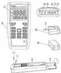
Figure 1. Components
Table 3. Components
| 1 | Display |
| 2 | Buttons |
| 3 | Thermocouple T1 input |
| 4 | Thermocouple T2 input (UT323 and UT325 only) |
| 5 | USB Port |
| 6 | SIGN Port - Over Limit Signal Output (UT323 and UT325 only) |
| 7 | NTC |
| 8 | Battery Door |
| 9 | 9V battery (8F22 ) |
LCD Display
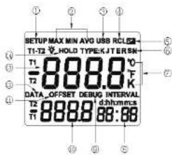
Figure 2. Display LCD Display
Table 4. LCD Display
| 1 | Setup is in progress when the icon blinks |
| 2 | Display readings of maximum, minimum and average |
| 3 | Data Transferring is in progress |
| 4 | Logged readings are displayed when the icon blinks |
| 5 | Low battery indicator. Replace the battery |
| 6 | The thermocouple type |
| 7 | The temperature units |
| 8 | Secondary Display 2 |
| 9 | Under Calibration mode when the icon blinks. The displayed reading is fixed |
| 10 | Secondary Display 1 |
| 11 | The thermocouple measurement includes an offset. See "Changing Setup Options" |
| 12 | Readings are being logged when the icon blinks |
| 13 | Primary Display |
| 14 | Data hold function is active. |
| 15 | The symbol of display backlight |
Buttons

Figure 3-a UT321 and UT323 Keypad

Figure 3-b UT322 and UT325 Keypad
Table 5. Buttons
| 1 | Press to turn the thermometer on or ofT |
| Press to turn the display backlight on and off. | |
| HOLD | Press to freeze or unfreeze the displayed readings |
| °C OFK | Press to switch between Celsius (°C), Fahrenheit(°F), and Kelvin (K) |
| MAX MIN | Press to step through the maximum, minimum, and average readings. Press and hold to exit this function. |
| TYPE(UT320UT325) | Press to step through K-, J-, T-, E- (R- S- N-) type thermocouple. |
| 3113-37(UT320UT325) | Press to select and show T1, T2 and T1-T2 (differential temperature measurement) in the primary or secondary display 1 |
| SEND | Press to enter USB mode and the USB icon blinks. Press again to exit USB mode. |
| STORE | Press to start or stop logging(See "Using Memory - Starting and Stepping Logging".) |
| RECALL | Press to show logged readingsPress again to stop. |
| SETUP | Press to start or exit Setup.Press to scroll the Setup option you want to change(See "Changing Setup Options") |
| ▲ | After entering the Setup mode, press to increase the displayed setting.(See "Changing Setup Options") |
| ▼ | After entering the Setup mode, press to decrease the displayed setting.(See "Changing Setup Options") |
| ENTER | Confirm button.(See "Changing Setup Options") |
Using the Thermometer
1) Plug the thermocouple(s) into the input connector(s).
2) Press the power button to turn on the thermometer.
3) Set the type of thermocouple(s) to be the same with the one plugged into the input connector(s).
If no thermocouple is plugged into the selected input terminal or the thermocouple is "open" or the over-range positive deviation is too big, the display shows".
Changing Setup Options
- Use Setup to change the following settings:
- Logging interval→Thermocouple type→Offset (T1) Offset (T2) (UT322 and UT325 only) Sleep Mode Time Frequency Time (S-T) Low Limit Alarm (Lo) (UT323 and UT325 only)→High Limit Alarm (Hi) (UT323 and UT325 only)→Over Limit Signal Output (SI) ON/OFF→UT323 and UT325 only) Normal Temperature Compensation (NTC) ON/OFF→DEBUG ON/OFF (UT323 and UT325 only) have setting and return to normal measurement mode.
Entering and Exiting Setup
When the thermometer is in Setup mode, the display shows and blinks SETUP
- Press SETUP to start or exit Setup
- Press SETUP to scroll through the Setup options you want to change.
Changing the Logging Interval
The logging interval determines how often the thermocouple stores logged readings in memory. You choose the length of the logging interval. See "Using Memory".
Press SETUP until the display shows INTERVAL
The thermometer stores logged readings at the end of each logging interval. You can select a logging interval by pressing ▲or▼. Holding down ▲or▼ causes the number to change more quickly. The maximum interval is 59:59 and the minimum interval is 00:00. When the logging interval is 00:00, you need to store the readings manually as the auto store feature will be disabled.
Changing the Thermocouple Type
-
Press SETUP until the display shows TYPE.
-
Press ▲ or ▼ to select the thermocouple type you want including K-, J-, E- type (UT323 and UT325 have extra R-, S- and N- type, UT321/UT325 can use TYPE button to change directly)).
Changing the Offset (T1)
-
Press SETUP until the display shows OFFSET and T1
-
Press ▲ or ▼ to change the offset value. The offset range is -6\~6.
Changing the Offset (T2)
-
Press SETUP until the display shows OFFSET and T2
-
Press ▲ or ▼ to change the offset value. The offset range is -6\~6.
Sleep Mode
- Press SETUP until the display shows SLP.
- Press ▲ or ▼ to change until the desired sleep lime is obtained, it is between 5–60 minutes.
- Holding down ▲ or ▼ causes the time to change more quickly.
- When the sleep mode time is less than 5 minutes, the display shows OFF which means disabling the sleep mode.
Changing the Line Frequency
-
Press SETUP until the display shows LINE.
-
Press ▲ or ▼ to select 60Hz or 50Hz
Setting the Time
- Press SETUP until the display shows S-T
- Press ENTER to toggle between time format 'h:m' and 'm:s'.
3 Press ▲ or ▼ until the display shows the correct time. The time is 24-hour format. - Holding down ▲ or ▼ causes the number to change more quickly.
- If you don't change this option, it means the time that the meter has run through currently.
- The system counts the time when the user turns on the thermometer. It will be automatically cleared once the Thermometer is dis-energized.
Setting the Low Limit Alarm (Lo) ((Only UT323 and UT325)
- Press SETUP until the display shows Lo.
- Press ▲ or ▼ until the display shows the correct low limit alarm.
- Holding down ▲ or ▼ causes the number to change more quickly
- Press ENTER to turn the low limit alarm off, the display shows OFF. Press ENTER again to turn the low limit alarm on, the display shows the low limit alarm reading
- When the tested temperature is over the limit, the thermometer beeps
- The Min.value for low alarm is the lower limit value of measuring range of the applied thermocouple.
- The Max. value for low alarm is the setting high alarm limit value if high alarm is enabled (if still higher than high alarm limit value, Max. value=High Alarm Limit Value-1), otherwise this Max. value is the upper limit value of measuring range of the applied thermocouple.
For example:
The Min. value of the low alarm of K type is -200°C.
The Max. value of the low alarm of K type is either High Alarm Limit Value-1 or +1372°C
The table below shows the measuring range of each type of thermocouple
| K type: -200.0°C to +1372°C (-328.0°F to +2501°F) |
| J type: -210.0°C to +1200°C (-346.0°F to +2192°F) |
| T type: -250.0°C to +400.0°C (-418.0°F to +752.0°F) |
| E type: -150.0°C to +1000°C (-236.0°F to +1832°F) |
Setting the High Limit Alarm (HI) (Only UT323 and UT325)
-
Press SETUP until the display shows HI.
-
Press ▲ or ▼ until the display shows the correct high limit alarm.
-
Holding down ▲ or ▼ causes the number to change more quickly
-
Press ENTER to turn the high limit alarm off, the display shows OFF. Press ENTER again to turn the high limit alarm on, the display shows the high limit alarm reading.
-
When the tested temperature is over the limit, the thermometer beeps
-
The Max.value for high alarm is the upper limit value of measuring range of the applied thermocouple.
-
The Min. value for high alarm is the setting low alarm limit value if low alarm is enabled (if still less than the low alarm limit value, Min. Value=Low Alarm Limit Value+1), otherwise this Min. value is the lower limit value of measuring range of the applied thermocouple.
For example:
The Max. value of the high alarm of K type is +1372°C
The Min.value of the high alarm of K type is either Low Alarm Limit Value+1 or -200°C.
The table below shows the measuring range of each type of thermocouple
| K type: -200.0°C to +1372°C (-328.0°F to +2501°F) |
| J type: -210.0°C to +1200°C (-346.0°F to +2192°F) |
| T type: -250.0°C to +400.0°C (-418.0°F to +752.0°F) |
| E type: -150.0°C to +1000°C (-238.0°F to +1832°F) |
Enabling or Disabling Over Limit Signal Output (Only UT323 and UT325)
-
Press SETUP until the display shows SI.
-
Press ▲ or ▼ to turn the over-limit signal output on or off. The display shows on or OFF.
-
With High/Low Limit Alarm set up and Over Limit Signal Output turned on already, the SIGN port of the thermometer will output the corresponding signal if the tested temperature is over or under the high or low limit. When the tested temperature is over the high limit, the SIGN port will output the high electric level signal. When the tested temperature is under the low limit, the SIGN port will output around 10Hz pulse signal.
Enabling or Disabling Normal Temperature Compensation (NTC)
-
Press SETUP until the display shows NTC
-
Press ▲ or ▼ to turn normal temperature compensation on or off. The display shows On or Off. It defaults to ON status at power-on.
Enabling or Disabling Debug (Only UT323 and UT325)
-
Press SETUP until the display shows DEBUG.
-
Press ▲ or ▼ to turn Debug on or off. The display shows on or off. The thermometer defaults to OFF status.
-
You can self-debug the thermometer when the Debug feature is turned on. (Refer to Measuring Temperatures - Debug)
Measuring Temperatures
Connecting a Thermocouple
Thermocouples are color-coded based on the North American ANSI Colour Code:
| Type | Colour | Type | Colour |
| J | Black | R | Green |
| K | Yellow | S | Green |
| T | Blue | N | Orange |
| E | Purple |
-
Plug a thermocouple into the input connector(s).
-
Set the same thermocouple type in the thermometer.
To change the thermocouple type, see "Changing Setup Options".
Displaying Temperatures
-
Press °C °FK to select the correct temperature unit.
-
Hold or attach the thermocouple(s) to the measured location.
The temperature shows in the selected unit on LCD.
Holding the Displayed Temperatures
-
Press HOLD to freeze the readings on the display. The display shows HOLD
-
Press HOLD again to turn off the HOLD function.
Turning on and off display backlight
-
Under temperature measurement mode, press to turn the display backlight on.
-
Press again to turn off the display backlight. The display backlight will not turn automatically off.
Viewing the MIN, MAX, and AVG Readings
-
Press MIN MAX to step through the maximum (MAX), minimum (MIN), or the average (AVG) readings.
-
Press and hold MIN MAX to exit MIN MAX mode.
Using the Offset to Adjust for Probe Errors
Use the offset option in Setup to adjust the thermometer's readings to compensate for the errors of a specific thermocouple.
-
Plug the thermocouple into the input connector.
-
Place the thermocouple in a known, stable temperature environment (such
as an ice bath or a dry well calibrator).
-
Allow the readings to stabilize.
-
In Setup change the offset until the display reading matches the debug temperature. (See "Changing Setup Options.")
Over Limit Alarm (Only UT323 and UT325)
Setting the low alarm and high alarm limit at the SETUP mode, the thermometer beeps when the measured temperature is higher or lower than the pre-set limit. (See "Changing Setup Options.")
Over Limit Signal Output (Only UT323 and UT325)
Setting the low and high limit signal output at the SETUP mode, the SIGN port output the corresponding signal when the measured temperature is higher or lower than the pre-set limit. (See "Changing Setup Options.")
Debug (Only UT323 and UT325)
After entering the Debug mode, you can self-debug. Follow the procedures as below:
- Debug point:
K- and J-type: -180°C, 0°C and 900°C
T type: -180°C, 0°C and 400°C
E type: -140°C, 0°C and 900°C
R- and S- type: 0°C and 1200°C
N type: -160°C, 0°C and 1200°C
Remark: 0°C is only for debugging K type.
- Debug method:
-
Connect T1 and T2 to standard voltage source.
-
Standard voltage source sources the voltage corresponding to
debug point.
-
Press HOLD to freeze the debug data.
-
Normal temperature debug:
Press MAX MIN when the thermometer is at Debug mode, secondary
display 1 shows the offset reading
Secondary display 2 shows the normal temperature
Press ▲ or ▼ to adjust the offset reading, the offset range is -6\~+6. Remark:
For Temperature VS Voltage table, refer to BS EN 60584 - 1:1996. Before carrying out the debug, please ensure your standard source has the accuracy up to the demand. Our company will not be liable for massive deviation occurring to the accuracy of the thermometer that has been caused by improper selection of standard source on users' side.
Using Memory
During a logging session, the thermometer stores logged readings in its memory.
The thermometer stores 00-99, total 100 sets of temperature readings. The stored readings are from primary display.
Starting and Stopping Logging
-
Set the logging interval. (See "Changing Setup Options.")
-
Press STORE to start logging.
DATA shows and blinks on LCD
-
Press STORE again to stop logging.
-
If you selected a manual logging interval, set the logging interval as 00:00. Press ENTER each time you want to store logged readings in memory. The secondary display 1 shows the logged reading. Each presses of ENTER will automatically store the logged readings in the next memory location. Press ▲ or ▼ would change the memory location, the empty location shows "----".
-
If you selected an auto logging interval, set the logging interval to any time except 00:00. After entering logging mode, the secondary display 2 shows "." Press ENTER to start storing readings in sequence according to the pre-set logging interval, the "-" blinks. Press ENTER again to pause auto logging, the "-" stop blinking. Press ENTER again to resume logging, the "-" blinks again.
Viewing Logged Readings
- Press RECALL to view logged readings
RCL shows and blinks on LCD
-
Press ▲ or ▼ to scroll through the logged readings, the default reading is the last stored reading prior to exiting the logging. The temperature unit will switch automatically along with the recalled data based on what have been stored during the logging.
-
The secondary display 1 shows its memory location. The secondary display 2 shows the system time when the data was logged. The primary display shows each logged reading.
-
Press ENTER causes the readings to change more quickly until memory location reaches 00.
Clearing Memory
-
Press STORE to enter logging mode, DATA shows and blinks on LCD.
-
Press and hold down STORE for 2 seconds, the display shows CLR.
-
Press ENTER to delete all the logged readings from memory. It is not possible to delete the logged readings one by one.
The display then shows *...*
Communicating with a PC
You can transfer the data from the thermometer's memory to a PC using the included Software.
Press SEND button and USB blinks on the display. It means the Thermometer has already been communicated normally to the PC. Details refer to the Installation Guide file in the Software.
Under the influence of radiated Radio-Frequency electromagnetic Field
the captioned models have a measurement error, it will be back to normal when the interference is removed.
Maintenance
Replacing the Battery
Replace the batteries as soon as the battery indicator appears. The possibility of false readings can lead to personal injury.
-
Turn off the thermometer.
-
Loosen the screw and remove the battery door.
-
Replace the battery with a new 9V battery (6F22). Reinstall the battery door and tighten the screw.
Cleaning the Case
Clean the surface of the thermometer with soft cloth or sponge dampened with water or mild detergent. Do not get water inside the thermometer, otherwise it may cause damage to internal circuits or the instrument.
Specifications
Environmental
| Operating Temperature | -10°C to 50°C(14°F to 122°F) |
| Storage Temperature | -40°C to +60°C(-14°F to +140°F) |
| Humidity | Non condensing <10°C (<50°F)95% RH: 10°C to 30°C (50°F to 86°F)75% RH: 30°C to 40°C (86°F to 104°F)45% RH: 40°C to 50°C (104°F to 122°F) |
General
| Certification | CE |
| Safety | EN61326: 2006, EN55022: 2006 and EM55024: 1998+A1+A2 |
Electrical
| Function | UT321 | UT322 | UT323 | UT325 | Input Protection |
| Type | K, J, T, E | K, J, T, E, R, S, N | 30V | ||
| Input | T1 | T1, T2 | T1 | T1, T2 | |
| Measurement Range | K type: -200.0°C to +1372°C (-328.0°F to +2501°F) | ||||
| J type: -210.0°C to +1200°C (-346.0°F to +2192°F) | |||||
| T type: -250°C to +400.0°C (-418°F to +752.0°F) | |||||
| E type: -150.0°C to +1000°C (-238.0°F to +1832°F) | |||||
| Display Resolution | 0.1°C °F/K.... (<1000) (T type below -200°C and R type, S type is 1°C °F/K)1.0°C °F/K.... (>1000) | ||||
| Measurement Accuracy | ±(0.5%+0.8°C(1.6°F)) | K-, J-, T-, E- type: ±(0.2%+0.6°C(1.2°F)) | |||
| R, S type: ±(0.2%+2°C(4°F))N type: ±(0.2%+1.5°C(3°F)) | |||||
| Below -10°C; add 0.5°C Below -200°C, add 12°C Type T Below -200°C: for reference only. | |||||
| Sampling Rate | 50 times per second, Updates 2-3 times per second | ||||
| Time | Relative Time | ||||
| Data Store | 0 ~ 99 sets | ||||
| Setup | Logging Interval, Thermocouple Type, Offset (T1), Offset (T2) (UT322 and UT325 only), Sleep Mode, Line Frequency, Time, High/Low Limit (UT323 and UT325 only), Over Limit Signal Output (UT323 and UT325 only), Normal Temperature Compensation, Debug (UT323 and UT325 only) | ||||
| Over Limit Alarm | N/A | Yes | |||
| Over Limit Signal | N/A | Yes | |||
| Power | One piece of 9V (NEDA1804 or 6F22 or 006P) | ||||
Accuracy is specified for ambient temperatures between 18°C(60°F) and 28°C
(82°F) for a period of 1 year, operating temperatures: -10°C \~ 50°C (14°F \~
122°F). The above specifications do not include thermocouple probe error.
*END *
This operating manual is subject to change without notice.
UNI-T
UNI-TREND TECHNOLOGY (CHINA) CO., LTD.
No6. Gong Ye Bei 1st Road.
Songshan Lake National High-Tech Industrial
Development Zone, Dongguan City,
Guangdong Province, Ch
Tel: (86-769) 8572 3888
http://www.uni-trend.com
说明书菲林做货要求:
- DIGITAL THERMOMETERS
- OVERVIEW
- SAFETY INFORMATION
- WARNING
- CAUTION
- GET ACQUAINTED WITH YOUR THERMOMETER
- USING THE THERMOMETER
- CHANGING SETUP OPTIONS
- ENTERING AND EXITING SETUP
- CHANGING THE LOGGING INTERVAL
- CHANGING THE THERMOCOUPLE TYPE
- CHANGING THE OFFSET (T1)
- CHANGING THE OFFSET (T2)
- SLEEP MODE
- CHANGING THE LINE FREQUENCY
- SETTING THE TIME
- SETTING THE LOW LIMIT ALARM (LO) ((ONLY UT323 AND UT325)
- FOR EXAMPLE
- SETTING THE HIGH LIMIT ALARM (HI) (ONLY UT323 AND UT325)
- ENABLING OR DISABLING OVER LIMIT SIGNAL OUTPUT (ONLY UT323 AND UT325)
- ENABLING OR DISABLING NORMAL TEMPERATURE COMPENSATION (NTC)
- ENABLING OR DISABLING DEBUG (ONLY UT323 AND UT325)
- MEASURING TEMPERATURES
- CONNECTING A THERMOCOUPLE
- DISPLAYING TEMPERATURES
- HOLDING THE DISPLAYED TEMPERATURES
- TURNING ON AND OFF DISPLAY BACKLIGHT
- VIEWING THE MIN, MAX, AND AVG READINGS
- USING THE OFFSET TO ADJUST FOR PROBE ERRORS
- OVER LIMIT ALARM (ONLY UT323 AND UT325)
- OVER LIMIT SIGNAL OUTPUT (ONLY UT323 AND UT325)
- DEBUG (ONLY UT323 AND UT325)
- DEBUG POINT
- DEBUG METHOD
- USING MEMORY
- STARTING AND STOPPING LOGGING
- VIEWING LOGGED READINGS
- CLEARING MEMORY
- COMMUNICATING WITH A PC
- MAINTENANCE
- REPLACING THE BATTERY
- CLEANING THE CASE
- SPECIFICATIONS
- END
- UNI-T
- UNI-TREND TECHNOLOGY (CHINA) CO., LTD
Brand : Uni-T
Model : UT325
Category : Environment thermometer