
AVU4004A - Audio/video extension Black Box - Free user manual and instructions
Find the device manual for free AVU4004A Black Box in PDF.


| Product Type | Audio/Video Extender |
| Brand | Black Box |
| Model | AVU4004A |
| Dimensions (approx.) | 120 mm x 80 mm x 25 mm |
| Weight (approx.) | 200 g |
| Power Supply | 5V DC via USB or included adapter |
| Power Consumption | 2.5W max |
| Video Resolution Support | Up to 1080p @ 60Hz |
| Audio Support | Stereo RCA or digital optical (TOSLINK) |
| Transmission Type | Wired (HDMI over single CAT5e/6) |
| Maximum Transmission Distance | Up to 50 meters |
| Input Interface | 1 x HDMI (Type A female) |
| Output Interface | 1 x RJ-45 (female) for CAT5e/6 |
| Supported Audio Formats | PCM 2.0, Dolby Digital, DTS |
| HDCP Support | Yes, HDCP 1.4 |
| Operating Temperature | 0°C to 40°C |
| Storage Temperature | -20°C to 60°C |
| Maintenance | Wipe with a soft dry cloth; do not use liquids |
| Safety | Keep away from moisture and heat sources |
| Spare Parts / Repairability | No user-serviceable parts; contact support for repairs |
Frequently Asked Questions - AVU4004A Black Box
User questions about AVU4004A Black Box
0 question about this device. Answer the ones you know or ask your own.
Ask a new question about this device
Download the instructions for your Audio/video extension in PDF format for free! Find your manual AVU4004A - Black Box and take your electronic device back in hand. On this page are published all the documents necessary for the use of your device. AVU4004A by Black Box.
USER MANUAL AVU4004A Black Box
Wizard Multimedia Extender LP
Extend quality SVGA video connections to multiple video displays that can be up to 492 feet away.
AVU4004A is the local module. Up to four AVU4001A-RX remote modules may be connected to a single AVU4004A local module.

Trademarks Used in this Manual
Black Box and the Double Diamond logo are registered trademarks, and ServSwitch is a trademark, of BB Technologies, Inc.
Mac is a registered trademark of Apple Computer, Inc.
Linux is registered trademark of Linus Torvalds.
Windows is a registered trademark of Microsoft Corporation.
NetWare is a registered trademark of Novell, Inc.
Sun is a trademark of Sun Microsystems, Inc.
Unix is a registered trademark of UNIX System Laboratories, Inc.
BSD is a registered trademark of UUNet Technologies, Inc.
Any other trademarks mentioned in this manual are acknowledged to be the property of the trademark owners.
We're here to help! If you have any questions about your application or our products, contact Black Box Tech Support at 724-746-5500 or go to blackbox.com and click on "Talk to Black Box."
You'll be live with one of our technical experts in less than 30 seconds.
Federal Communications Commission and Industry Canada Radio Frequency Interference Statements
This equipment generates, uses, and can radiate radio-frequency energy, and if not installed and used properly, that is, in strict accordance with the manufacturer's instructions, may cause interference to radio communication. It has been tested and found to comply with the limits for a Class A computing device in accordance with the specifications in Subpart B of Part 15 of FCC rules, which are designed to provide reasonable protection against such interference when the equipment is operated in a commercial environment. Operation of this equipment in a residential area is likely to cause interference, in which case the user at his own expense will be required to take whatever measures may be necessary to correct the interference.
Changes or modifications not expressly approved by the party responsible for compliance could void the user's authority to operate the equipment.
This digital apparatus does not exceed the Class A limits for radio noise emission from digital apparatus set out in the Radio Interference Regulation of Industry Canada.
1.1 What's Included 6
1.2 Additional Items You May Need 6
- Overview 7
2.1 Cascading units to support more displays 7
2.2 Wizard Multimedia Extender LP features 8
- Installation....9
3.1 Locations....9
3.2 Mounting the modules – desk or rack 9
3.2.1 Desk mount....9
3.2.2 Rack mount 10
3.3 Connections ...... 11
3.3.1 Connections at the local module....11
3.3.2 Connections at each remote module 14
3.3.3 Cascade connections ....15
3.4 Video sharpness adjustment 16
3.4.1 To adjust video sharpness.... 16
3.5 Resetting the local module 17
- Operation....18
4.1 Indicators 18
4.1.1 Status indicators.... 18
4.1.2 Link indicators 18
Appendix A. Troubleshooting....19
A.1 Troubleshooting 19
A.2 Safety Information 20
1. Specifications
Approvals: CE, FCC
Hardware Compatibility: All computers with SVGA analog video interfaces
Software Compatibility: Operates with all known software and operating systems including Windows®, Linux®, Unix®, BSD, all Sun® OS, all Mac® OS, NetWare®, etc.
Connectors: Video: DB15 female x 2
(local module) Links: RJ45 x 4
Other: Power jack
Connectors: Video: DB15 female
(remote module) Link: RJ45
Operating Temperature: 32 to 104°F (0 to 40°C)
Power: DC jack (power adapter included)
Input: 100–240 VAC, 50/60 Hz
Output: 5VDC, 12.5W
1.1 What's Included
Your package should include the following items. If anything is missing or damaged, contact Black Box at 724-746-5500 or info@blackbox.com.
- Wizard Multimedia Extender LP local module (AVU4004A)
• Power adapter and power cord
• (4) Self-adhesive feet
• CD-ROM containing this user manual in PDF format
• Analog video link cable (6 feet)
1.2 Additional Items You May Need
• One to four Remote modules (AVU4001A-RX)
- Suitable CATx link cables up to 492 feet (150m)
- Rack mount fascia plate
• 19" rackmount chassis
2. Overview
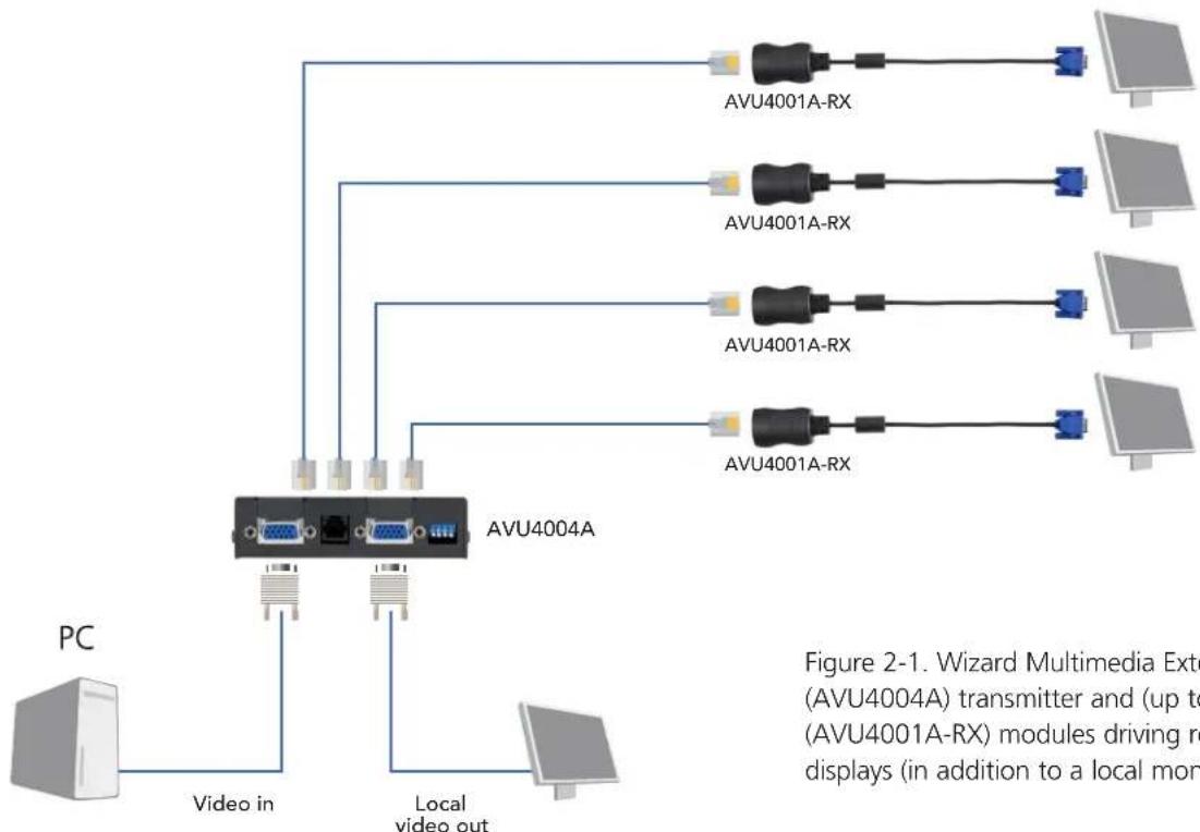
Thank you for choosing the Wizard Multimedia Extender LP (AVU4004A) which allows you to distribute high quality analogue video to four video displays, each of which can be up to 492 feet (150 meters) away. All links are made using simple twisted pair cables (Category 5 or higher) with a compact AVU4001A-RX module at each remote end. Each remote module converts the long distance transmission signals back into high quality analogue video signals for each display. All power for the remote modules is fed along the CATx cabling to allow quick and straightforward installation at each remote location.
flowchart
graph TD
    PC["PC"] -->|Video in| A["AVU4004A"]
    A -->|Local video out| B["Local video"]
    A --> C["AVU4001A-RX"]
    A --> D["AVU4001A-RX"]
    A --> E["AVU4001A-RX"]
    A --> F["AVU4001A-RX"]
    C --> G["Computer"]
    D --> H["Computer"]
    E --> I["Computer"]
    F --> J["Computer"]
    style A fill:#f9f,stroke:#333
    style B fill:#ccf,stroke:#333
    style C fill:#cfc,stroke:#333
    style D fill:#cfc,stroke:#333
    style E fill:#cfc,stroke:#333
    style F fill:#cfc,stroke:#333
    style G fill:#ffc,stroke:#333
Figure 2-1. Wizard Multimedia Extender LP (AVU4004A) transmitter and (up to) four (AVU4001A-RX) modules driving remote displays (in addition to a local monitor).
2.1 Cascading units to support more displays
If you need to drive more than four video displays you can connect up to three AVU4004A units in cascade. To do this, the local video out port of the first AVU4004A unit is fed to the video in port of the next one.

Figure 2-2. Cascading Wizard Multimedia Extender LP transmitters to allow more remote video displays to be driven.
2.2 Wizard Multimedia Extender LP features
The Wizard Multimedia Extender LP unit is housed within a compact, durable, metallic enclosure with connectors and indicators mounted on the two end panels.

Figure 2-3. End panel containing four link connectors, status indicators and power input.

Figure 2-4. End panel containing video in and out ports, reset switch and reserved port.
3. Installation
3.1 Locations
Please consider the following important points when planning the positions of your Wizard Multimedia Extender LP modules:
• Take care not to exceed the maximum link cable lengths of 492 feet (150m) per link.
- Ensure that the local module(s) is/are as close as possible to the source PC system and the remote modules are similarly close to the video displays. Each remote module can be connected directly to the video display and no power is required.
- Wherever possible, choose routes for the CATx twisted pair link cables that avoid mains power cables.
- Remember a mains power socket is required for each local module. The remote modules do not require external power.
- Consult the precautions listed within the Safety information section.
3.2 Mounting the modules – desk or rack
The Wizard Multimedia Extender LP modules can be situated on a desk or alternatively, for larger installations, mounted within an optional rack mount chassis.
3.2.1 Desk mount
Apply the supplied self-adhesive rubber feet to the underside of the module as shown in Figure 3-1:

natural_image
Line drawing of a device casing with two buttons and a downward arrow indicator (no text or symbols)Figure 3-1. Applying the supplied self-adhesive rubber feet to the underside of the module
3.2.2 Rack mount
1 Place the rack securing plate (available as a separate kit) onto the front of the module and secure it with the two countersunk screws.
2 Orient the Wizard Multimedia Extender LP module on its side.
3 Slide the module into the required rack position. The rectangular cut-out in the front upper lip of the rack allows the two screws on the module's upper edge to slide through.
4 The rack mount chassis has a series of holes in its floor that are spaced to accommodate the two screws on the module's lower edge. Ensure that the screws correctly locate into the two holes of the chosen slot. The rack securing plate on the module should now be flush with the front of the rack mount chassis.
5 Use the third (pan-head) screw, in the top hole of the rack securing plate to fasten the module to the rack as shown in Figure 3-2:

Figure 3-2. Fixing the module into the rack
3.3 Connections
Connections to the AVU4004A (local) and AVU4001A-RX (remote) modules do not need to follow the precise order given in this user guide although it is recommended that you do not apply power to the local module until all other connections have been made.
3.3.1 Connections at the local module
3.3.1.1 To connect video from the source PC system
1 Connect the supplied video cable to the socket labeled ☐ on the local module.
2 Attach the other end of the video cable to the appropriate VGA video output socket on the host system.
3 Optionally, connect a local monitor to the socket labeled OUT

Figure 3-3. Connecting the video signal from the PC
3.3.1.2 DDC information
DDC information about the video displays is not sent from the receiver modules. Instead, the local module holds a standard set of DDC details which are suitable for most video displays. If the standard details are not suitable, temporarily connect the local module (using the ☐ port) directly to the video display that is to be emulated and power on the screen and the local module. In cascaded installations, only the initial local module needs to be taken through this procedure.
If the DDC information is different to that already held, the red indicator (adjacent to the LINK4 socket) will flicker rapidly for 2 to 3 seconds while the new information is stored.
If a problem occurs while attempting to harvest DDC information, the red indicator on the local module will show a number of distinct flashes. Note the number of flashes in case you need to contact technical support, but otherwise retry the procedure.
3.3.1.3 To connect the link cables
The links between the local and remote modules are made using between one and four twisted pair cables, specified to Category 5 or higher. Each cable carries video signals and power to each remote module.

Figure 3-4. Link cable lengths
1 Attach the connector of the first link cable (no longer than 492 feet, 150m) to the socket labeled LINK1 on the local module. There should be a click when the cable is fully inserted and locked in place.

Figure 3-5. Connecting the link cables
2 Attach the connectors of the remaining link cables (no longer than 492 feet, 150m each) to the sockets labeled LINK2 to LINK4, as required.
IMPORTANT: The signals and power connections sent through the link cables are NOT compatible with standard networking equipment and could cause damage if connected. Do not connect the local or remote modules to any other devices.
3.3.1.4 To connect the power supply
NOTE: Please read and adhere to the electrical safety information given within the Safety information section (Appendix A.2) of this guide. In particular, do not use an unearthed power socket or extension cable.
1 Attach the output connector of the power supply to the socket labeled POWER on the local module.

Figure 3-6. Connecting the power supply input to the local module
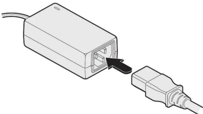
2 Insert the IEC connector of the power cord into the corresponding socket of the power supply.
natural_image
Diagram of a USB port connected to a cable, showing internal socket and cable connector (no text or symbols)Figure 3-7. Connecting the IEC power cord
3 When all other connections have been made at the local and remote modules, connect the other end of the power cable to a nearby earthed mains socket.
3.3.2 Connections at each remote module
3.3.2.1 To connect the link cable and video display
The link from the local module to each remote module is made using a twisted pair cable, specified to Category 5 or higher at a maximum length of 492 feet (150 meters).
NOTE: Where possible, avoid laying the twisted pair link cable(s) alongside power cables.
1 Attach the connector of the link cable to the socket on the remote module. There should be a click when the cable is fully inserted and locked in place.

Figure 3-8. Connecting the remote (AVU4001A-RX) module
2 Attach the VGA connector of the module to the input socket of the video display.
No power input is required for the module.
If the video image requires adjustment, please refer to the section 3.4 Video sharpness adjustment.
3.3.3 Cascade connections
Where more remote video displays need to show the same output from the host system, it is possible to cascade up to three local modules to provide control for a total of up to twelve screens.
Cascading these units is a simple case of connecting the video output of the first local module to the video input of the next one; with each local module able to drive up to four video displays. It is recommended that you cascade no more than three local modules as there will be a slight degradation in signal quality with each cascade link.
3.3.3.1 To connect multiple local modules in cascade
1 Connect the supplied video cable to the socket labeled ☐ on the first local module (the one linked to the host system).
2 Attach the other end of the video cable to the socket labeled ON on the next local module.
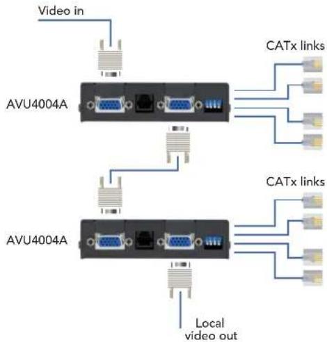
Figure 3-9. Cascade connection

Figure 3-10. Connecting two local modules in cascade
3 Optionally, repeat steps 1 and 2 for a third local module.
4 Make CATx links between each local module and its related remote modules as usual.
3.4 Video sharpness adjustment
Each remote module has a video adjustment to control picture sharpness on the connected video display screen.
3.4.1 To adjust video sharpness
1 On the host system, display a suitable high contrast image (ideally with one or more black vertical lines on a white background (e.g. a capital 'H' at 72 points in a word processor).

Figure 3-11. Use a high contrast figure with sharp vertical edges for best results
2 Insert a small screwdriver into the adjustment screw on the side of the remote module.

natural_image
Line drawing of a USB router with a screwdriver inserted (no text or symbols)Figure 3-12. Use a standard flatblade screwdriver to adjust image sharpness
3 Turn the screw fully clockwise - you should see a bright white shadow to the right of your high contrast image
4 Turn the screw anti-clockwise until the white shadow disappears and the edges of your image become sharp.
Note: As link cable lengths increase and more remote modules are cascaded, color separation effects may become noticeable within displayed video images, particularly at higher resolutions. These effects are called 'skew' and result from differing delays on the red, green and blue color signals as they travel to the remote modules. If such results occur, ensure that link cables are no longer than they need to be or try using 'low-skew' cables.
3.5 Resetting the local module
It is possible to reset the local module either by disconnecting and reconnecting the power input or by using switch 4 of the miniature switch block:

Figure 3-13. Use switch 4 to reset the local module
Momentarily click switch 4 to the ON position and then return it to its OFF position. The local module will reset itself.
Note: All other switches are reserved for future use and should remain OFF.
4. Operation
In operation, the Wizard Multimedia Extender LP modules are designed to be completely transparent - high quality video from the source PC system is played as normal, the only difference is that the video displays are up to 492 feet (150m) away.
4.1 Indicators
4.1.1 Status indicators
The Wizard Multimedia Extender LP local module is equipped with two main status indicators adjacent to the LINK4 socket.
- GREEN: When lit, indicates the presence of power and a video input into the module. If the input video is removed, power to the remote modules will be cut and this indicator will flash to indicate standby mode. Operation will automatically resume once video is reinstated.
- RED: Flashes while DDC programming is taking place (see 3.3.1.2 DDC information for details). If a problem occurs while attempting to harvest DDC information, this indicator will show a number of distinct flashes. Note the number of flashes in case you need to contact technical support, but otherwise retry the procedure.

4.1.2 Link indicators
Additionally, the Wizard Multimedia Extender LP local module features two indicators per link socket.
- GREEN: When lit, indicates that power and video are being supplied to the remote module.
- YELLOW: Flashes if the link cable is disconnected or if line power is overloaded.

If you experience problems when installing or using the modules, please check through this section for a possible solution.
No video image is received at the remote module.
- Check that the green status indicator (adjacent to the LINK 4 socket) is lit on the local module. If it is not then there is a power or video input problem. If the green status indicator is flashing then there is no input video, possibly because the host system has gone into standby; or simply that the input cable is not correctly connected. The transmitter unit requires power from its supplied power adapter.
- Check the link cable(s) that connect the transmitter and remote module(s) for soundness. If possible, try using an alternative twisted pair link connection between the modules.
- Check the yellow indicator on the associated link socket. If the yellow indicator is flashing continuously, check that the corresponding remote module is properly connected.
Alternatively, this output may have been overloaded. Disconnect the cable and reconnect it to check.
Note: The yellow indicators for all unused link ports will flash.
- If the sharpness control is set too high, the monitor may not be able to display a picture. Try reducing the sharpness setting. Please refer to section 3.4 Video sharpness adjustment.
- If not already fitted, connect a monitor to the port of the transmitter module and check for a correct video image output.
- Check that all of the miniature configuration switches are in the OFF position during normal operation.
Power is applied via the power supply but the transmitter module operation has stopped.
- The transmitter unit has an internal automatic cut-out fuse to protect against power surges. To reset, remove power from the transmitter for one second and then reconnect.
A.2 Safety Information
- For use in dry, oil free indoor environments only.
- Do not use to link between buildings.
- Not suitable for use in hazardous or explosive environments or next to highly flammable materials.
- Ensure that all twisted pair interconnect cables are installed in compliance with all applicable wiring regulations.
- Do not connect the CATx link interface (RJ45 style connector) to any other equipment, particularly network or telecommunications equipment.
- Where possible, avoid laying the twisted pair link cable(s) alongside power cables.
- Warning – the power adapter contains live parts.
- No user serviceable parts are contained within the power adapter - do not dismantle.
- The primary means to cease operation of the modules is to remove the power adapter lead. Ensure that the power adapter is positioned near to the equipment and is easily accessible.
- Do not use the power adapter if the power adapter case becomes damaged, cracked or broken or if you suspect that it is not operating properly.
- Replace the power adapter with a manufacturer approved type only.
- If you use a power extension cable with the modules, make sure the total ampere rating of the devices plugged into the extension cable do not exceed the cable's ampere rating. Also, make sure that the total ampere rating of all the devices plugged into the wall outlet does not exceed the wall outlet's ampere rating.
- Do not attempt to service the modules yourself.
- The modules and power supplies can get warm in operation – do not situate them in an enclosed space without any ventilation.
- The modules do not provide ground isolation and should not be used for any applications that require ground isolation or galvanic isolation.
- Use only with grounded outlets at both the computer and monitor. When using a backup power supply (UPS), power the computer, the monitor and the transmitter module from the same supply.
Black Box Tech Support: FREE! Live. 24/7.
Tech support the way it should be.

natural_image
Black and white photo of a smiling woman wearing a headset, with blue background (no text or symbols)Great tech support is just 30 seconds away at 724-746-5500 or blackbox.com.

BLACK BOX®
NETWORKSERVICES
About Black Box
Black Box Network Services is your source for more than 118,000 networking and infrastructure products. You'll find everything from cabinets and racks and power and surge protection products to media converters and Ethernet switches all supported by free, live 24/7 Tech support available in 30 seconds or less.
© Copyright 2012. Black Box Corporation. All rights reserved.
AVU4004A, rev. 1


- Extend quality SVGA video connections to multiple video displays that can be up to 492 feet away.
- Trademarks Used in this Manual
- Federal Communications Commission and Industry Canada Radio Frequency Interference Statements
- Specifications
- What's Included
- Additional Items You May Need
- Overview
- Cascading units to support more displays
- Wizard Multimedia Extender LP features
- Installation
- Locations
- Mounting the modules – desk or rack
- Desk mount
- Rack mount
- Connections
- Connections at the local module
- To connect video from the source PC system
- DDC information
- To connect the link cables
- To connect the power supply
- Connections at each remote module
- To connect the link cable and video display
- Cascade connections
- To connect multiple local modules in cascade
- Video sharpness adjustment
- To adjust video sharpness
- Resetting the local module
- Operation
- Indicators
- Status indicators
- Link indicators
- No video image is received at the remote module.
- Power is applied via the power supply but the transmitter module operation has stopped.
- A.2 Safety Information
- Black Box Tech Support: FREE! Live. 24/7.
- BLACK BOX®
- NETWORKSERVICES
- About Black Box
Brand : Black Box
Model : AVU4004A
Category : Audio/video extension