
One S3 - Desktop Computer ANTEC - Free user manual and instructions
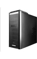
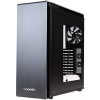
Find the device manual for free One S3 ANTEC in PDF.


| Product Type | Mid Tower Computer Case |
| Brand | Antec |
| Model | One S3 |
| Form Factor | ATX, Micro-ATX, Mini-ITX |
| Dimensions (L x H x D) | 200 x 470 x 480 mm |
| Weight | 6.5 kg |
| Material | Steel, Plastic |
| Power Supply | Not included (ATX PS2 compatible) |
| Maximum PSU Length | 160 mm |
| Drive Bays - 3.5" | 2 internal |
| Drive Bays - 2.5" | 2 internal (shared with 3.5" bays) |
| Expansion Slots | 7 |
| Front Ports | 2x USB 3.0, Audio In/Out |
| Cooling - Front | 2x 120mm fan (optional) |
| Cooling - Rear | 1x 120mm fan (pre-installed) |
| Cooling - Top | 2x 120mm fan (optional) |
| Maximum GPU Length | 360 mm |
| Maximum CPU Cooler Height | 155 mm |
| Filters | Front and bottom dust filters |
| Side Panel | Solid steel |
| Maintenance | Clean dust filters regularly with a damp cloth |
| Safety | Rounded edges, stable base |
| Spare Parts & Repairability | Standard screws, fan filters available; modular design |
| General Information | Designed for efficient airflow and easy assembly |
Frequently Asked Questions - One S3 ANTEC
User questions about One S3 ANTEC
0 question about this device. Answer the ones you know or ask your own.
Ask a new question about this device
Download the instructions for your Desktop Computer in PDF format for free! Find your manual One S3 - ANTEC and take your electronic device back in hand. On this page are published all the documents necessary for the use of your device. One S3 by ANTEC.
USER MANUAL One S3 ANTEC

One / One S /
One S3
User
Manual
One / One S / One S3 User Manual
Congratulaons on your purchase of your Antec One / One S / One S3!
When building a PC, it's important to use hardware you're comfortable working with. From Antec, the team behind dozens of award-winning enclosures since 1986, comes the One / One S / One S3, the gaming case that gives you everything you need right out of the box at an aracve price. This enclosure is stocked with features you value – USB 3.0, ample cooling and tool-less 5.25" & 3.5" drive bays – so that you can put your PC together with ease and get to the fun stu. If you're looking for high quality gaming essenals at an aordable cost, then this enclosure is the One for you.
The One / One S / One S3 does not include a power supply. Make sure you choose a power supply that is compatible with your computer components and has a long enough power harness to reach your motherboard and peripheral devices. We recommend our High Current Gamer or Earthwas power supplies for the latest ATX specicaon compliance, broad compatibility, and power savings capability.
At Antec, we connually rene and improve our products to ensure the highest quality. As such, your new chassis may dier slightly from the descripon in this manual due to improvements applied for the opmal building experience. As of the date of publicaon, all features, descripons, and illustraons in this manual are correct.
Disclaimer
This manual is intended only as a guide for Antec's computer enclosures. For more comprehensive instrucons on installing the motherboard and peripherals, please refer to the manuals that come with those components.
Table of Contents
Secon 1: Introducon
1.1 Geng to Know Your Chassis....5
1.2 Chassis Specicaons....6
1.3 Included Screws 7
Secon 2: Hardware Installaon
2.1 Seng Up 9
2.2 Removing the Side Panels and Front Bezel....9
2.3 Motherboard Installaon....10
2.4 Installing KUHLER H 2 O Liquid Coolers....11
2.5 Power Supply Installaon 11
2.6 External 5.25" Device Installaon....12
2.7 Internal 2.5" Device Installaon ....13
2.8 Internal 3.5" Device Installaon ....14
2.9 Cable Management....14
Secon 3: Front I/O Ports
3.1 USB 3.0....16
3.2 AC'97 / HD Audio Ports....16
3.3 Power Switch / Reset Switch / Hard Disk Drive LED Connectors....17
3.4 Rewiring Motherboard Header Connecons....18
Secon 4: Cooling System
4.1 Included Fans 20
4.2 Oponal Fans 21
4.3 Air Filters....22
Secon 1
Introducon
One / One S / One S3 User Manual
1.1 Geng to Know Your Chassis
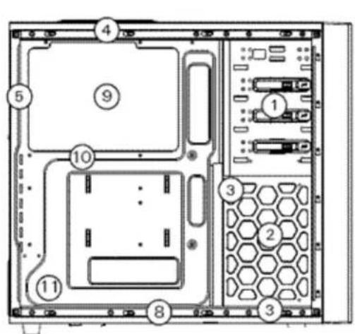

One

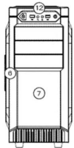
One S / One S3
- 3 x 5.25" drive bays
- 5 x 3.5" drive bays
- 2 x 2.5" drive bays
- 1 x 120 mm top exhaust fan (standard)
- 1 x 120 mm rear exhaust fan (standard)
- 1 x 120 mm side intake fan (oponal)
- 1 x 120 mm front intake fan (oponal)
- 1 x 120/140 mm boom intake fan (oponal)
- CPU cutout
- Motherboard mount: Standard ATX, microATX or Mini-ITX
- Power supply mount
- Front ports: 2 x USB 3.0, Audio In/Out
1.2 Chassis Specicaons
| Chassis Type | Mid Tower |
| Chassis Color | Black |
| Dimensions | 17.2" (H) x 8.2" (W) x 19.2" (D)438 mm (H) x 208 mm (W) x 488 mm (D) |
| Weight | One: 10.8 lbs / 4.9 kgOne S / One S3: 10.4 lbs / 4.7 kg |
| Cooling | One:- 1 x 120 mm top exhaust fan- 1 x 120 mm rear exhaust fan- 1 x 120 mm side intake fan (oponal)- 1 x 120 mm front intake fan (oponal)- 1 x 120 mm / 140 mm boom fan (oponal)One S / One S3:- 1 x 120 mm top blue LED exhaust fan- 1 x 120 mm rear exhaust fan (oponal)- 1 x 120 mm side intake fan (oponal)- 1 x 120 mm front intake fan (oponal)- 1 x 120 mm / 140 mm boom fan (oponal) |
| Drive Bays | - 3 x 5.25" tool-less drive bays- 5 x 3.5" tool-less drive bays- 2 x 2.5" drive-bays |
| Expansion Slots | 7 |
| Motherboard Size | Standard ATX, microATX, Mini-ITX |
| Front I/O Panel | - Audio In/Out- Power and Reset buonsOne / One S3:- 2 x USB 3.0 with internal motherboard connectorOne S:- 2 x USB 2.0 ports |
1.3 Included Screws
An inventory of all screws and intended usage and quantity is provided here:
A. PSU screws (10)
B. Motherboard standos (3:4 preinstalled)
C. Motherboard screw (9)
D. 5.25"/2.5" oponal drive screw (10)
E. Standard fan screws (4)
F. Front panel fan screws (2)
G. Drive bay rails for 3.5" (5 pairs)
H. Zip es (2)


Secon 2
Hardware Installaon
One / One S / One S3 User Manual
2.1 Seng Up
When working in your case, please keep the following in mind:
- Put the case upright on a at, stable surface so that the rear panel (power supply and expansion slots) is facing you.
- Handle all components and cards with care.
- To avoid electrostac discharge, ground yourself periodically by touching an unpainted metal surface or by using a wrist grounding strap.
- Before you connect a cable, ensure that both connectors are correctly aligned and oriented.
- Do not sit on your chassis. Although it is constructed of heavy-duty steel and internally reinforced, it is not designed to support the weight of an adult, and may buckle.
- Do not use your ngernails to separate edges or li the sides of the chassis, as paint chipping or injury may occur.
- Place the panel thumbscrews aside in a safe place.
- Exercise cauon and control when handling chassis interiors. We strongly recommend taking the appropriate me and care when working inside the chassis. Avoid hurried or careless moons.
2.2 Removing the Side Panels and Front Bezel
To remove the le and right side panels:
- Remove each set of two thumbscrews.
- Slide the panel you want to remove toward the back of the case approximately 2 cm until it stops.
- Pull the panel free of the chassis.
You need to remove the front bezel in order to access the air Iters and conduct maintenance.
To remove the front bezel:
- Grip the bezel by the boom and pull forward. The bezel will pop free of the chassis.
2.3 Motherboard Installaon
Before proceeding, check the manual for your CPU cooler to nd out if there are steps you must do before installing the motherboard.
Make sure you have the correct I/O panel for your motherboard. If the panel provided with the chassis isn't suitable, please contact your motherboard manufacturer for the correct I/O panel.
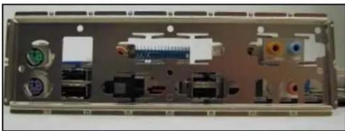
Make sure you have the correct I/O panel.
This case comes with 5 preinstalled motherboard standos. These are posioned for Standard ATX motherboards but can be relocated to accommodate other form factors.
- Align the motherboard with the stando holes on the motherboard tray and remember or mark which holes are lined up.
- Install standos as needed and put the motherboard in.
- Screw your motherboard into the standos with the provided motherboard moung screws.

The following instructs how to install the Antec KUHLER H2O liquid CPU cooler (620 / 920). For any other CPU coolers, please consult your manufacturer's installaon guide.
Cauon:
Check your motherboard's CPU socket to ensure its compatibility with the KUHLER H 2 O. The KUHLER H 2 O 620 / 920 is compatible with the following CPU sockets:
Intel ® LGA 1155 / 1156 / 1366 / 2011 *
AMD ® AM2 / AM3 / AM2+ / AM3+
*Your unit may not contain the LGA 2011 mounng bracket. To receive this bracket, please contact Antec customer support (informaon is listed at end of manual).
**Be sure to install the KUHLER H₂O with the end of the tubes posioned at the boom of the radiator.
- Remove the rear fan by unscrewing the fan from the back of the chassis.
- Preparing the KUHLER H 2 O backplate is specific to your CPU socket. Please refer to the KUHLER H 2 O installaon guide, available at hp://www.antec.com/Believe_it/product.php?id=Mjc2OCYxNw== (KUHLER H 2 O 620) or hp://www.antec.com/Believe_it/product.php?id=NzA0MzcWJjE3 (KUHLER H 2 O 920) for more informaon.
- Prepare the retenon ring according to the CPU socket you're using.
- Complete installaon according to the KUHLER H 2 O instrucons.
2.5 Power Supply Installaon
- With the case upright, place the power supply in the case and align the rear of the unit with the mounng holes.
- Aach the power supply to the case with the screws provided.

Attach the power supply with the provided screws.
2.6 External 5.25" Device Installaon
The One / One S / One S3 can support up to three 5.25" devices.
- Remove the side panels and front bezel as directed in Secon 2.2.
- Remove the drive bay cover by pressing out on the two small tabs on either side of the cover, then pushing the cover into the front of the bezel.
- Replace the front bezel on the front of the chassis.
- Slide your 5.25" drive through the front of the chassis until it lines up ush with the front bezel. You will feel the drive lock into posion.
- If you need more clearance on the inside of the chassis for your drive, pull the drive bay tab on the inside of the chassis toward you and push the drive in further.
Note: You can onponally secure your drive with screws for extra stability (D in Secon 1.3)

Slide you drive until it locks.

Pull on the tab to adjust drive bay clearance.
2.7 Internal 2.5" Device Installaon
There are two 2.5" drive mounng locaons in the One / One S / One S3: at the base of the drive cage and a dedicated mount in the middle of the drive cage.
To install at the base of the drive cage:
- Remove the side panels as described in Secon 2.2.
- Secure your drive with the 2.5" screws provided (D in Secon 1.3). Your drive will each at the base of the drive cage at the boom of the case, with screws axing from the underside of the case.

To install in the middle of the drive cage:
Note: The 2.5" drives install from the right side of the case.
- Remove the side panels as described in Secon 2.2.
- Insert your device into the dedicated drive bay, with the connectors facing you.
- You can onponally secure the drive to the cage with the 2.5" screws provided (D in Secon 1.3)

2.8 Internal 3.5" Device Installaon
The One / One S / One S3 includes 5 pairs of 3.5" drive rails. You will need 1 pair per 3.5" drive.
- Line up the drive rail pins to the sides of your 3.5" drive. Ensure that the squeeze-tabs are aligned on the side of your drive that does not have power or data connectors.
- Snap the rail into place.
- Repeat steps 1-2 for the other side of the 3.5" drive.
- Pinch the ends of the drive rails together and slide the drive into the 3.5" bay unl it locks into posion.

Pinch the ends of the drive rails and then slide your drive into the 3.5" bay until it locks into position.
2.9 Cable Management
There is a cable management compartment between the motherboard and right side panel. You can tuck excess cables in this compartment or route them to the drive bays through one of the four conveniently-placed cable management holes.
Choose the cables you would like to pass through the holes behind the motherboard tray. Pull them through the hole toward the right side of the case. Feed the cables back through the inseron point nearest the desnaon of the cable.

Secon 3
Front I/O Ports
One / One S / One S3 User Manual
3.1 USB Ports
One / One S3: The One and One S3 come with two front panel USB 3.0 ports and includes an internal motherboard connector. Connect these in the same way you would a standard front panel with an internal header connector.
One S: The One S comes with two front panel USB 2.0 ports. Connect these in the same way you would a standard front panel with an internal header connector.

Align the connector properly to prevent damage to your motherboard.

| Pin | Signal Names | Pin | Signal Names |
| 1 | USB Power 1 | 2 | USB Power 2 |
| 3 | Negative Signal 1 | 4 | Negative Signal 2 |
| 5 | Positive Signal 1 | 6 | Positive Signal 2 |
| 7 | Ground 1 | 8 | Ground 2 |
| 9 | Key (No Connection) | 10 | Empty Pin |
USB 2.0 pin assignments
3.2 AC'97 / HD Audio Ports
There is an Intel ® standard 10-pin AC'97 connector and an Intel ® 10-pin HDA (High Denion Audio) connector linked to the front panel of the chassis.
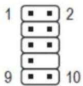
| Pin | Signal Names (HDA) | Pin | Signal Names (AC'97) |
| 1 | MIC2L | 1 | MIC In |
| 2 | AGND | 2 | GND |
| 3 | MIC2R | 3 | MIC Power |
| 4 | AVCC | 4 | NC |
| 5 | FRO-R | 5 | Line Out(R) |
| 6 | MIC2_JD | 6 | Line Out(R) |
| 7 | F_IO_SEN | 7 | NC |
| 8 | Key (no pin) | 8 | Key (no pin) |
| 9 | FRO-L | 9 | Line Out (L) |
| 10 | LINE2_JD | 10 | Line Out (L) |
You can connect either the AC'97 or the HDA connector, depending on your motherboard. Locate the internal audio connectors from your motherboard or sound card and connect the corresponding audio cable. Consult your motherboard or sound card manual for the pin-out posions. Even if your system supports both standards, only use one connector.
3.3 Power Switch / Reset Switch / Hard Disk Drive LED Connectors
Connected to your front panel are LED leads for power and HDD acvity, as well as switch leads for the power and reset buons. Each these to the corresponding connectors on your motherboard. Consult your motherboard manual for speci pin header locaons. For LEDs, colored wires are posive (+). White or black wires are negave (−). If the LED does not light up when the system is powered on, try reversing the conncon. For more informaon on connecng LEDs to your motherboard, see your motherboard user's manual.
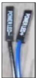

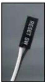

Front panel leads
Note: Polarity (positive and negative) does not maer for switches.
3.4 Rewiring Motherboard Header Connecons
There may come a me when you need to reconfigure the pin-out of a motherboard header connector. Examples could be for your USB header, audio input header, or some other front panel connector such as the Power Buon connector.
Before performing any work, please refer to your motherboard user's manual or your motherboard manufacturer's website to conrm the pin-out needed for your connector. We strongly recommend making a notated drawing before beginning work so that you can recover if your work gets disturbed.
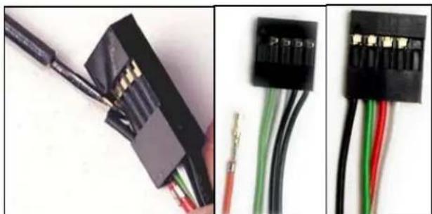
Front panel headers
Determine which wires you need to remove in order to rewire your plug to match the USB pin-outs on your motherboard (refer to your motherboard user's manual). Working on one connector at a me, use a very small ahead screwdriver or similar tool to li up on the black tab located beside the gold posts (squares). This will allow you to easily slide out the pins from the USB plug.
Working carefully so as not to damage the wires, connectors, or pins, slowly remove the pin from the connector. Repeat these steps for each wire you need to change.
Working carefully so as not to damage the wires, connectors or pins, slowly insert the pin into the correct slot of the connector then snap closed the black tab that was lied in step 1. Repeat these steps for each wire you need to change.
Secon 4
Cooling System
One / One S / One S3 User Manual
4.1 Included Fans
One: The One comes with two standard fans (yellow outline) – a rear 120 mm exhaust fan and a top 120 mm exhaust fan.
The red rectangles indicate additional fan mounts. Mounng procedures for these fans is discussed in Secon 4.2.
One S / One S3: The One S and One S3 come with one standard fan (yellow outline) – a top 120 mm blue LED exhaust fan.
The red rectangles indicate additional fan mounts. Mounng procedures for these fans is discussed in Secon 4.2.

One fan locations
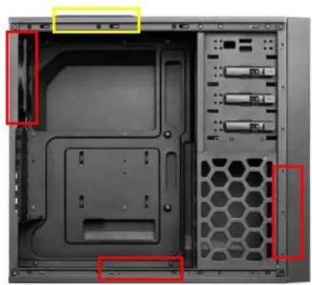
One S / One S3 fan locations
120 mm Single Speed Fan Specicaons
| Size: | 120 x 25 mm fan |
| Rated Voltage: | 12V |
| Operang Voltage : | 10.8V ~ 13.2V |
| Speed (RPM) | Input Current | Airow | Stac Pressure | Acousc Noise | Input Power |
| 1200 | 0.20A (Max.) | 1.2 m3 /min (42.6 CFM) | 1.0 mm- H2O (0.04 inch- H2O ) | 23.7 dBA | 2.4W |
4.2 Oponal Fans
One: The One includes mounts for up to three more fans. These mounts are as follows:
- 1 x front intake 120 mm mount
- 1 x side 120 mm mount
- 1 x boom 120/140 mm mount
One S / One S3: The One S / One S3 includes mounts for up to four more fans. These mounts are as follows:
- 1 x front intake 120 mm mount
- 1 x side 120 mm mount
- 1 x boom 120/140 mm mount
- 1 x rear 120 mm mount
- Remove the front bezel as outlined in Secon 2.2.
- Align the fan with the screw holes and screw in the fan in the top-le and lower-right holes (as pictured).
- Screw in the long fan screws (F in Secon 1.3).

Screw in the fan in the top-left and lower-right holes.
Side 120 mm fan
On the le panel, there is a 120 mm fan mount for additional graphics cards cooling.
- Remove the le side panel as outlined in Secon 2.2.
- Align your fan with the moung holes. The fan should be installed with air blowing into the case.
- Screw in the fan with the included screws (E in Secon 1.3).
Boom 120/140 mm fan
At the base of the case, there is a fan mount that can t either a 120 mm or 140 mm fan for additional air intake.
- Remove the le side panel as outlined in Secon 2.2. Rest the case on its side so you have access to both sides of the fan mount.
- Align your fan with the moung holes. The fan should be installed on the inside of the case, with air blowing in.
- Screw in the fan with the included screws (H in secon 1.3).
Rear 120 mm fan – One S / One S3 only
A rear exhaust fan can be installed for additional airrow out of the case.
- Remove the le side panel as outlined in Secon 2.2.
- Align your fan with the moung holes. The fan should be installed with air blowing out of the case.
- Screw in the fan with the included screws (H in secon 1.3).
4.3 PSU Air Filter
The One / One S / One S3 features a PSU air intake Iter that can be removed and cleaned.
To remove the PSU Iter:
- Pull the lter out toward you using the tab at the back of the chassis.

Screw the rear fan into place by first aligning it with the rear screw holes.

Pull the filter toward you using the tab outside the chassis.
Antec, Inc.
47900 Fremont Blvd.
Fremont, CA94538
tel: 510-770-1200
fax: 510-770-1288
Antec Europe B.V.
Stugartstraat 12
3047 AS Roerdam
The Netherlands
tel: +49-40-226139-22
fax: +31 (0) 10 437-1752
Technical Support
US & Canada
1-800-22ANTEC
customersupport@antec.com
Europe
+31 (0) 10 462-2060
europe.techsupport@antec.com
www.antec.com
© Copyright 2012 Antec, Inc. All rights reserved.
All trademarks are the property of their respective owners.
Reproducon in whole or in part without wrien permission is prohibited.



- ONE / ONE S / ONE S3 USER MANUAL
- DISCLAIMER
- TABLE OF CONTENTS
- SECON 1: INTRODUCON
- SECON 2: HARDWARE INSTALLAON
- SECON 3: FRONT I/O PORTS
- SECON 4: COOLING SYSTEM
- SECON 1
- INTRODUCON
- 1.1 GENG TO KNOW YOUR CHASSIS
- 1.2 CHASSIS SPECICAONS
- 1.3 INCLUDED SCREWS
- SECON 2
- HARDWARE INSTALLAON
- 2.1 SENG UP
- 2.2 REMOVING THE SIDE PANELS AND FRONT BEZEL
- 2.3 MOTHERBOARD INSTALLAON
- CAUON
- 2.5 POWER SUPPLY INSTALLAON
- 2.6 EXTERNAL 5.25" DEVICE INSTALLAON
- 2.7 INTERNAL 2.5" DEVICE INSTALLAON
- 2.8 INTERNAL 3.5" DEVICE INSTALLAON
- 2.9 CABLE MANAGEMENT
- SECON 3
- FRONT I/O PORTS
- 3.1 USB PORTS
- 3.2 AC'97 / HD AUDIO PORTS
- 3.3 POWER SWITCH / RESET SWITCH / HARD DISK DRIVE LED CONNECTORS
- 3.4 REWIRING MOTHERBOARD HEADER CONNECONS
- SECON 4
- COOLING SYSTEM
- 4.1 INCLUDED FANS
- 4.2 OPONAL FANS
- SIDE 120 MM FAN
- BOOM 120/140 MM FAN
- REAR 120 MM FAN – ONE S / ONE S3 ONLY
- 4.3 PSU AIR FILTER
Brand : ANTEC
Model : One S3
Category : Desktop Computer