
Liebert GXT3 1500VA - Uninterruptible power supply Emerson - Free user manual and instructions
Find the device manual for free Liebert GXT3 1500VA Emerson in PDF.


| Product Type | Uninterruptible Power Supply (UPS) |
| Brand | Emerson |
| Model | Liebert GXT3 1500VA |
| Power Capacity | 1500VA / 1350W |
| Input Voltage | 120V (range: 80-150V) |
| Output Voltage | 120V ± 2% (pure sine wave) |
| Frequency | 50/60 Hz auto-sensing |
| Battery Type | Sealed lead-acid (VRLA), hot-swappable |
| Typical Backup Time | 12 minutes at half load, 5 minutes at full load |
| Dimensions (H x W x D) | 3.5 x 17.2 x 22.0 inches (89 x 437 x 559 mm) |
| Weight | 52.9 lbs (24 kg) |
| Transfer Time | 2-4 ms typical |
| Outlets | 8 x NEMA 5-15R (6 battery backup + 2 surge-only) |
| Communication | USB, RS-232, optional SNMP card slot |
| Operating Temperature | 32°F to 104°F (0°C to 40°C) |
| Safety Certifications | UL 1778, cUL, CE, FCC Class A |
| Battery Replacement | Hot-swappable - replace without powering down connected equipment |
| Warranty | 3 years (2 years on battery) |
| Maintenance | Keep vents clear; clean with dry cloth; self-test every 3 months |
| Reparability | Field-replaceable batteries and fan; user-replaceable air filters |
Frequently Asked Questions - Liebert GXT3 1500VA Emerson
User questions about Liebert GXT3 1500VA Emerson
0 question about this device. Answer the ones you know or ask your own.
Ask a new question about this device
Download the instructions for your Uninterruptible power supply in PDF format for free! Find your manual Liebert GXT3 1500VA - Emerson and take your electronic device back in hand. On this page are published all the documents necessary for the use of your device. Liebert GXT3 1500VA by Emerson.
USER MANUAL Liebert GXT3 1500VA Emerson
natural_image
Exterior view of a black server tower with ventilation grilles and control panel (no visible text or symbols)
natural_image
Front view of a black server rack with EMSON logo and Liebert button (no readable text or symbols beyond branding)TABLE OF CONTENTS
IMPORTANT SAFETY PRECAUTIONS ....1
SAVE THESE INSTRUCTIONS ....1
GLOSSARY OF SYMBOLS....3
1.0 PRODUCT DESCRIPTION 4
1.1 Features 4
1.2 Available Models 4
1.3 Appearance and Components 5
1.3.1 Appearance 5
1.3.2 Rear Panel Features.... 5
1.4 Major Components 6
1.5 Operating Mode 7
1.5.1 Mains (AC) Mode 7
1.5.2 Manual Bypass Mode 8
1.5.3 Battery Mode 8
1.5.4 Battery Recharge Mode 8
1.5.5 Frequency Converter Mode 8
2.0 INSTALLATION 9
2.1 Unpacking and Inspection....9
2.2 What's Included 9
2.3 Preparation for Installation....9
2.3.1 Installation Environment....9
2.4 Mechanical Installation 10
2.4.1 Tower Installation 10
2.4.2 Rack Installation 11
2.5 Cable Connection 14
2.5.1 Connecting to AC Mains and Loads 15
2.5.2 Connecting Battery Cables 15
2.6 Connecting Communication Cables.... 16
2.6.1 Connecting USB Communication Cables 16
2.6.2 Installing the Optional Liebert IntelliSlot Card and Communication Cables ..... 16
3.0 OPERATION AND DISPLAY PANEL....17
3.1 Control Buttons 17
3.1.1 On/Alarm Silence/Manual Battery Test button 17
3.1.2 Standby/Manual Bypass button 17
3.2 Indicators 18
3.2.1 Level Indicators 18
3.2.2 UPS Status Indicators 19
4.0 OPERATION 20
4.1 Startup Checklist for the Liebert GXT3 20
4.2 Starting the UPS 20
4.3 Manual Battery Test 20
4.4 Manual Bypass.... 20
4.5 Shut Down the Liebert GXT3 21
4.6 Disconnecting Input Power from the Liebert GXT3.... 21
5.0 COMMUNICATION 22
5.1 Liebert IntelliSlot Communication Cards.... 22
5.1.1 Liebert MultiLink.... 22
5.2 USB Port Communication 23
5.2.1 Configuration Program 23
5.3 Terminal Block Communication 24
5.3.1 Any Mode Shutdown 24
5.3.2 Battery Mode Shutdown 25
5.3.3 On Battery 25
5.3.4 Low Battery 25
6.0 MAINTENANCE 26
6.1 Replacing the Internal Battery Pack.... 26
6.1.1 Battery Replacement Procedures 26
6.2 Battery Charging 27
6.3 Precautions.... 27
6.4 Checking UPS Status.... 27
6.5 Checking UPS Functions....28
7.0 TROUBLESHOOTING 29
7.1 UPS Symptoms.... 29
7.1.1 Indicators 29
7.1.2 Audible Alarm.... 30
7.2 Troubleshooting 30
8.0 BATTERY CABINET....32
9.0 SPECIFICATIONS....33
9.1 Product Warranty Registration.... 37
FIGURES
Figure 1 Liebert GXT3-700RT230 - GXT3-3000RT230 UPS 5
Figure 2 Rear panel components, Liebert GXT3 230V 700VA, 1000VA and 1500VA models....5
Figure 3 Rear panel components, Liebert GXT3 230V 2000VA models ..... 5
Figure 4 Rear panel components, Liebert GXT3 230V 3000VA models 6
Figure 5 Operating principle diagram 6
Figure 6 Support bases 10
Figure 7 Remove the front plastic bezel cover 10
Figure 8 Rotate the operation and display panel.... 11
Figure 9 Tower installation....11
Figure 10 Pulling inner member from each bracket assembly ..... 12
Figure 11 Installing rear member of each bracket assembly 12
Figure 12 Installing front member of each bracket assembly.... 13
Figure 13 Fastening rear member and front member together 13
Figure 14 Installing inner members.... 13
Figure 15 Installing rack-mount ears.... 14
Figure 16 Insert the UPS.... 14
Figure 17 Operation and display panel 17
Figure 18 Battery level indicators.... 18
Figure 19 Load level indicators.... 18
Figure 20 Terminal Block Communication pin layout.... 24
Figure 21 Removing the front plastic bezel cover and battery door 26
Figure 22 Disconnecting the battery plug and battery connector (front view).... 26
Figure 23 Pulling out the battery 26
Figure 24 Battery level indicator 29
Figure 25 Battery cabinet 32
TABLES
Table 1 UPS models, power ratings 4
Table 2 Specification of input circuit breaker.... 15
Table 3 Functions of the On/Alarm Silence/Manual Battery Test button ..... 17
Table 4 Functions of the Standby/Manual Bypass button.... 17
Table 5 UPS status indicators.... 19
Table 6 Output voltage option, all models 23
Table 7 Indicator descriptions....29
Table 8 Audible alarm description 30
Table 9 Troubleshooting table.... 30
Table 10 Specifications of GXT3-700RT230 and GXT3-1000RT230 UPS.... 33
Table 11 Specifications of the Liebert GXT3-1500RT230, GXT3-2000RT230 and GXT3-3000RT230 .... 34
Table 12 Operating temperature parameters.... 35
Table 13 Battery cabinet specifications .... 35
Table 14 Battery run times 36

WARNING
Observe all cautions and warnings in this manual. Failure to do so may result in serious injury or death.
Refer all UPS and battery service to properly trained and qualified service personnel. Do not attempt to service this product yourself.
Opening or removing the cover may expose you to lethal voltages within this unit even when it is apparently not operating and the input wiring is disconnected from the electrical source.
Never work alone.
SAVE THESE INSTRUCTIONS
This manual contains important safety instructions that must be followed during the installation and maintenance of the UPS and batteries. Read this manual thoroughly before attempting to install or operate this UPS.
UPS Safety Notes
The UPS contains no user-serviceable parts except the internal battery pack. Do not remove the cover. Removing the cover may result in electric shock and will invalidate any implied warranty.
The UPS has an internal battery, so the output receptacles of the UPS may carry live voltage even if the UPS is not connected to mains input power.
Before moving or rewiring the UPS, disconnect mains input power and the battery and make sure that the UPS is completely shut down. Otherwise, the output terminal may carry live voltage, presenting an electric shock hazard.
To ensure human safety and normal UPS operation, the UPS must be properly grounded before use.
When the UPS is connected to an IT power distribution system, the short-circuit protection device must be installed on the neutral line.
Install and use the UPS in the following environments:
• Temperature: 0°C to 40°C (32 - 104°F); relative humidity: 0% to 95%, non-condensing)
- Out of direct sunlight
- Away from heat source
- Stable surface, not subject to vibrations or shocks
- Away from dust and other particulates
- Away from corrosive substances, salts and flammable gases
Keep the air inlet and outlet of the UPS unobstructed. Poor ventilation will increase the UPS internal temperature and can shorten the life of the UPS and its batteries.
Keep liquid and other foreign objects away from the UPS.
In case of fire, use a dry chemical fire extinguisher to put out the fire. Using a fluid fire extinguisher may cause electric shock.
This UPS is not intended for use with life support and other designated critical devices. Maximum load must not exceed that shown on the UPS rating label. This UPS is designed for data processing equipment. If uncertain, consult your local dealer or Emerson representative.
Battery Safety

CAUTION
Do not dispose of the battery in a fire. The battery may explode.
Do not open or damage the battery. Released electrolyte is toxic and is harmful to skin and eyes. If electrolyte comes into contact with the skin, wash the affected area immediately with plenty of clean water and get medical attention.

CAUTION
A battery can present a risk of electrical shock and high short-circuit current. The following precautions should be observed when working on batteries:
- Remove watches, rings and other metal objects.
- Use tools with insulated handles.
- Wear rubber gloves and boots.
- Do not lay tools or metal parts on top of batteries.
- Disconnect charging source prior to connecting or disconnecting battery terminals.
- Determine if the battery is inadvertently grounded. If it is inadvertently grounded, remove the source of the ground. Contact with any part of a grounded battery can result in electrical shock. The likelihood of such shock will be reduced if grounds are removed during installation and maintenance (applicable to a UPS and a remote battery supply not having a grounded supply circuit).
ELECTROMAGNETIC COMPATIBILITY—The Liebert GXT3 series complies with the limits for a Class A digital device. Operating this device in a residential area is likely to cause harmful interference that users must correct at their own expense.
The Liebert GXT3 series complies with the requirements of EMC Directive 2004/108/EC and the published technical standards. Continued compliance requires installation in accordance with these instructions and use of accessories approved by Emerson.
Information for the Protection of the Environment
UPS SERVICING—This UPS makes use of components dangerous for the environment (electronic cards, electronic components). The components removed must be taken to specialized collection and disposal centers.
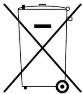
NOTICE TO EUROPEAN UNION CUSTOMERS: DISPOSAL OF OLD APPLIANCES—This product has been supplied from an environmentally aware manufacturer that complies with the Waste Electrical and Electronic Equipment (WEEE) Directive 2002/96/CE.
The “crossed-out wheelie bin” symbol at right is placed on this product to encourage you to recycle wherever possible. Please be environmentally responsible and recycle this product through your recycling facility at its end of life. Do not dispose of this product as unsorted municipal waste. Follow local municipal waste ordinances for proper disposal provisions to reduce the environmental impact of waste electrical and electronic equipment (WEEE).
For information regarding the scrapping of this equipment, please browse http://www.eu.emersonnetworkpower.com (“Products session” or “Contact us” session) or call our worldwide technical support.
natural_image
Simple line drawing of a cylindrical container with two crossed X marks, no text or symbols present.• Toll Free: 00 80011554499
• Toll Number Based in Italy: +39 0298250222
GLOSSARY OF SYMBOLS

Risk of electrical shock

Indicates caution followed by important instructions
AC input

AC output

Requests the user to consult the manual

Indicates the unit contains a valve-regulated lead acid battery

Recycle

DC voltage

Equipment grounding conductor

Bonded to ground

AC voltage

ON/Alarm Silence/Battery Test

OFF/Bypass

WEEE
1.0 PRODUCT DESCRIPTION
The Liebert GXT3 is a compact, online uninterruptible power system (UPS) that continuously conditions and regulates its output voltage. The Liebert GXT3 is designed to supply microcomputers and other sensitive electronic equipment with clean sine wave input power, 700VA to 3000VA at 230V.
Upon generation, AC power is clean and stable. However, during transmission and distribution it is subject to voltage sags, spikes and complete failure that may interrupt computer operations, cause data loss and damage equipment.
The Liebert GXT3 protects equipment from these disturbances. The Liebert GXT3 continuously charges its batteries from the mains, enabling it to supply power to connected loads, even when the mains fail.
This section describes the UPS, its features, models, appearance and components, operating principles and operating mode.
1.1 Features
The UPS includes the following features:
- Intelligent battery management to extend the battery life
- Operation and display panel with LED for monitoring load percentage and battery capacity independently
- Flexible network management with Liebert MultiLink™ software
- Fan fault self-inspection and automated diagnostic function
- Intelligent fan operation, automatically changing rotation speed depending on system requirements, to decrease power consumption and noise
- Input circuit breaker to ease recovery from overloads
• CE mark and safety approval from CE - Communication options: USB port, Liebert IntelliSlot ® port and terminal block communication
• Dry contacts for remote monitoring - Input power factor greater than 0.99
- Output voltage selection function
1.2 Available Models
Available models of the UPS are shown in Table 1:
Table 1 UPS models, power ratings
| Model Nominal Power Rating | |
| GXT3-700RT230 | 700VA/630W |
| GXT3-1000RT230 | 1000VA/900W |
| GXT3-1500RT230 | 1500VA/1350W |
| GXT3-2000RT230 | 2000VA/1800W |
| GXT3-3000RT230 | 3000VA/2700W |
1.3 Appearance and Components
1.3.1 Appearance
The Liebert GXT3 rack/tower models in various power ratings have the same general appearance, controls and features (see Figure 1). The various rack/tower models differ largely in the type of receptacles each has.
Figure 1 Liebert GXT3-700RT230 - GXT3-3000RT230 UPS

1.3.2 Rear Panel Features
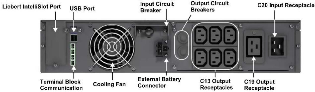
The rear panel of the Liebert GXT3 has these features:
• USB port
- Cooling fan
• C19 output receptacle (GXT3-3000RT230 only)
• Six C13 output receptacles
- Input circuit breaker
- Liebert IntelliSlot
- Communication terminal block
- Input receptacle
Figure 2 Rear panel components, Liebert GXT3 230V 700VA, 1000VA and 1500VA models
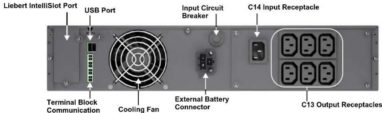
Figure 3 Rear panel components, Liebert GXT3 230V 2000VA models

Figure 4 Rear panel components, Liebert GXT3 230V 3000VA models
1.4 Major Components
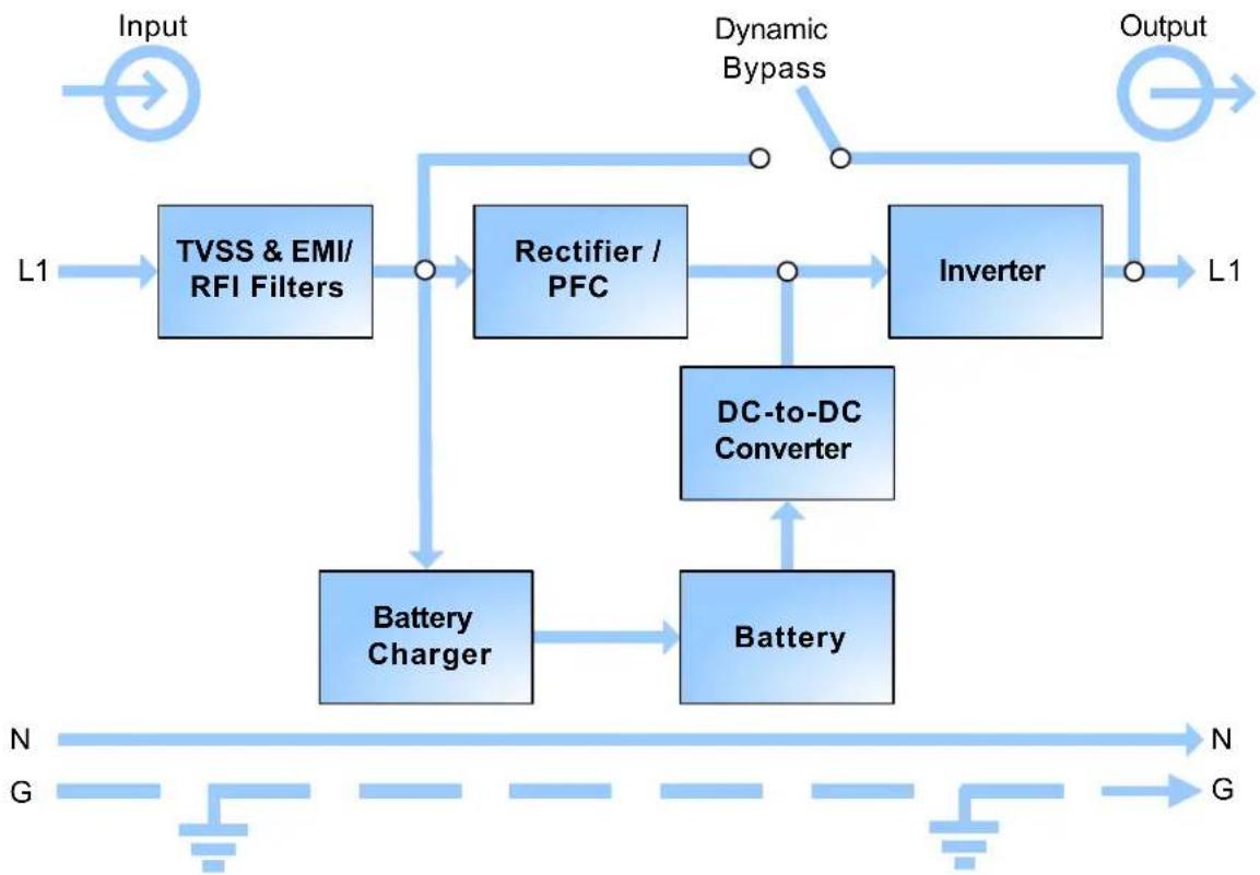
The operating principle of the UPS is shown in Figure 5.
Figure 5 Operating principle diagram
flowchart
graph TD
    A["Input"] --> B["TVSS & EMI/RFI Filters"]
    B --> C["Rectifier / PFC"]
    C --> D["Inverter"]
    D --> E["Output"]
    F["Battery Charger"] --> G["Battery"]
    H["DC-to-DC Converter"] --> G
    I["Dynamic Bypass"] --> C
    J["N"] --> K["G"]
    L["G"] --> K
    M["L1"] --> B
    N["G"] --> K
The UPS is composed of mains input, TVSS and EMI/RFI filters, rectifier/PFC, inverter, battery charger, DC-to-DC converter, battery, dynamic bypass and UPS output.
Transient Voltage Surge Suppression (TVSS) and EMI/RFI Filters
The Liebert GXT3 has surge protection and filters that protect the connected load from power surges and sags, electromagnetic interference (EMI) and radio frequency interference (RFI). These features can minimize any surges or interference present in the mains power. The filters also prevent surges or interference generated by the UPS from adversely affecting other devices connected on the same branch as the UPS.
Rectifier/Power Factor Correction (PFC) Circuit
In normal operation, the Liebert GXT3's rectifier/power factor correction (PFC) circuit converts mains power to regulated DC power for use by the inverter while ensuring that the wave shape of the input current used by the UPS is near ideal. Extracting this sine wave input current achieves two objectives:
• Efficient power use by the UPS
- Reduced reflected harmonics
This results in cleaner power being available to other devices in the building that are not protected by the UPS.
Inverter
In normal operation, the Liebert GXT3's inverter utilizes the DC output of the PFC circuit to produce precise, regulated sine wave AC power. When mains power fails, the inverter receives DC power from the battery through the DC-to DC converter. In either operation mode, the UPS inverter is online, continuously generating clean, precise, regulated AC output power.
Battery Charger
The battery charger utilizes energy from the mains power and precisely regulates it to continuously float charge the batteries. The batteries are being charged whenever the Liebert GXT3 is plugged in, even when the UPS is not turned on.
DC-to-DC Converter
The DC-to-DC converter raises the DC voltage from the battery to the optimum operating voltage for the inverter. This allows the inverter to operate continuously at its optimum efficiency and voltage, increasing reliability.
Battery
The Liebert GXT3 utilizes valve-regulated, nonspillable, lead acid batteries. To maintain battery design life, operate the Liebert GXT3 in an ambient temperature of 0° C to 25° C ( 32° F to 77° F).
Optional external battery cabinets are available to extend battery run times.
Dynamic Bypass
The Liebert GXT3 provides an alternate path for mains power to the connected loads in the unlikely event of a UPS malfunction. Should the Liebert GXT3 have an overload, overtemperature, or UPS failure condition, the UPS automatically transfers the connected loads to bypass.

NOTE
The bypass power path does not protect the connected loads from disturbances on the mains.
1.5 Operating Mode
The UPS operation modes include the following: Mains (AC) Mode, Bypass Mode, Battery Mode, Battery Recharge Mode and Frequency Converter Mode.
For the descriptions of operation mode indicators and control buttons, refer to 3.0 - Operation and Display Panel.
1.5.1 Mains (AC) Mode
During Mains (AC) Mode, the mains provides energy to the Liebert GXT3. The filters, PFC circuit and inverter process this power to provide high-level power to connected loads. Meanwhile, the UPS maintains the batteries in a fully charged state.
1.5.2 Manual Bypass Mode
Manual Bypass Mode occurs when the Standby/Manual Bypass button is pressed and held for about 2 seconds while the Liebert GXT3 is in Mains (AC) Mode. Bypass operation is indicated by an audible alarm and illuminated amber bypass indicator. (If other indicators are illuminated, refer to 7.0 - Troubleshooting). During Bypass Mode, mains power bypasses the inverter and provides energy to the connected load.
NOTICE
Turning off the UPS in Bypass Mode will result in loss of output power.
1.5.3 Battery Mode
The Liebert GXT3 enters Battery Mode when mains power fails or is outside acceptable values. The battery system supplies power through the DC-to-DC converter to the inverter to generate clean AC power for the connected loads.
When the Liebert GXT3 enters Battery Mode, the UPS sounds a half-second beep at 10-second intervals. When approximately 2 minutes of run time remains, the beeps sound every 5 seconds to warn that the battery is getting low (this Low Battery Warning is user-configurable).
In Battery Mode, the AC Input indicator is Off and the Battery Level indicators illuminate to warn that a mains problem has occurred. Each battery level indicator represents a 20% capacity level. As capacity decreases, fewer indicators remain illuminated. Refer to 7.0 - Troubleshooting.
For approximate battery run times, refer to 9.0 - Specifications. The times in Table 14 are approximate. They are based on resistive load and an ambient temperature of 25° C ( 77° F). To increase this time, turn off non-essential loads (such as idle computers and monitors) or add optional external battery cabinets.
NOTICE
Turning Off the Liebert GXT3 when it is in Battery Mode will result in loss of output power. If the UPS is turned Off manually, it must be manually restarted after mains power returns. If the UPS is turned Off by a communication signal or because the batteries are depleted, it will operate as selected in the configuration program for Auto-Restart (Refer to 5.2.1 - Configuration Program).
1.5.4 Battery Recharge Mode
Once mains power is applied to the Liebert GXT3, the Battery Charger begins charging the batteries.
1.5.5 Frequency Converter Mode
All models of the Liebert GXT3 are capable of frequency conversion. Frequency Conversion Mode can be selected using the configuration program. Allowable frequency operating modes include:
• Auto Sensing - 50Hz or 60 Hz – Bypass Enabled
• Auto Sensing - 50Hz or 60 Hz – Bypass Disabled
• Frequency Converter - 50Hz – Bypass Disabled
- Frequency Converter - 60Hz – Bypass Disabled

NOTE
The default for all models of the Liebert GXT3 is “Auto Sensing - 50Hz or 60 Hz – Bypass Enabled.”

CAUTION
Do not touch the AC input receptacle when the UPS is operating. AC input voltages may still be present even when the AC input indicator is Off.
2.0 INSTALLATION
2.1 Unpacking and Inspection
Unpack the UPS and conduct the following checks:
- Inspect the UPS for shipping damage. If any shipping damage is found, report it to the carrier and your local dealer or Emerson representative immediately.
- Check the accessories against the delivery list. If there is any discrepancy, contact your local dealer or your Emerson representative immediately.
2.2 What's Included
With GXT3 UPS
• Terminal Block Communication terminals
- Compact Disk with:
- Liebert MultiLink
- Configuration Program
- User Manual
• USB Cable: one, 2m (6-1/2 ft.) long
- Mounting hardware, including screws and handles
- Plastic tower stand sets: 2 (four pieces)
- Warnings, Safety Instructions booklet and WEEE recycling sheet (ISO 14001 compliance)
- for 700VA - 1500VA: (2) 10A IEC C13 C14 Output Cable, 2m (6-1/2 ft.) long
• for 2000VA - 3000VA:
• (3) 10A IEC C13 C14 Output Cable, 2m (6-1/2 ft.) long
• (1) CEE 7/7 (Schuko) to IEC C20 Input Cable, 2.5m (8-1/5 ft.) long
• (1) BS1363 (UK) to IEC C20 Input Cable, 2.5m (8-1/5 ft.) long

NOTE
The GXT3 External Battery Cabinet shipping package includes one battery cabinet, two spacers for tower configuration and one DC power cable.
2.3 Preparation for Installation
2.3.1 Installation Environment
- Install the UPS indoors in a controlled environment, where it cannot be accidentally turned Off. The installation environment should meet the specifications in 9.0 - Specifications.
- Place the UPS in an area where airflow around the unit is unrestricted and away from water, flammable liquids, gases, corrosives and conductive contaminants. Avoid direct sunlight.

NOTE
Operating the Liebert GXT3 in temperatures above 25°C (77°F) reduces battery life.
Installation Clearances
Maintain a clearance of at least 100mm (4 inches) in the front and rear of the Liebert GXT3. Do not obstruct the air inlets on the front panel and rear panel of the UPS; blocking the air inlets reduces ventilation and heat dissipation, shortening the service life of the Liebert GXT3.
2.4 Mechanical Installation
The Liebert GXT3 may be installed as a tower or in a rack, depending on space and use considerations. The Liebert GXT3 may be used alone, as a single UPS, or with up to four battery cabinets.

NOTE
When installing the UPS or making input and output connections, comply with all relevant safety codes and standards.
2.4.1 Tower Installation
To install the Liebert GXT3 as a tower:
- Take out support bases from the accessories (see Figure 6).
Figure 6 Support bases

flowchart
graph LR
    A["Support Bases"] --> B["Connectors"]
    B --> C["Spacers"]
    C --> D["Final Component"]
-
If optional Liebert external battery cabinets will be connected to the Liebert GXT3, take out the spacers delivered with the battery cabinet.
-
Connect the spacers and the support bases as shown in Figure 6. Each Liebert GXT3 needs two assembled support bases, one in the front and one in the rear.
-
Adjust the direction of the operation and display panel and logo on the Liebert GXT3.
a. Remove the front plastic bezel cover (see Figure 7).
Figure 7 Remove the front plastic bezel cover

b. Pull the operation and display panel, rotate it 90 degrees clockwise and snap it back into position (see Figure 8).
Figure 8 Rotate the operation and display panel

c. Pull the logo on the front plastic bezel cover, rotate it 90 degrees clockwise and snap it back into position. The rotated front plastic bezel cover is shown in Figure 9.
d. Replace the front plastic bezel cover on the Liebert GXT3. At this point, the UPS operation and display panel and logo have been rotated 90 degrees clockwise, which provides upright viewing for users.
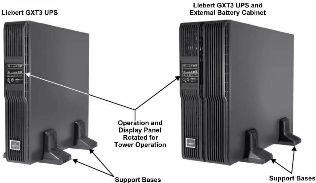
- Place the Liebert GXT3 and any battery cabinets on the support bases. Each Liebert GXT3 needs four support bases, as shown in Figure 9.
Figure 9 Tower installation
2.4.2 Rack Installation

NOTE
- When the Liebert GXT3 is installed in a rack, the UPS must be supported by a shelf, brackets, or slide rails on each side. The factory-supplied rack-mount ears cannot support the weight of the UPS. They are used to move the UPS into and out of the rack and attach the UPS to the rack.
- Mounting hardware and slide rails are sold separately. Contact your local dealer or Emerson representative for these options and any assistance.
To install a Liebert GXT3 UPS in a rack:
- Unpack the two bracket assemblies and mounting hardware from the rack-mounting kit (P/N: RMKIT18-32). Bracket assembly includes inner member, front member and rear member.
They are interchangeable between left-hand and right-hand. Mounting hardware includes M4 screws and M5 screws.
- Remove inner member of each bracket assembly by extending it to its outermost position, depressing the retaining latch and then pulling the inner member from the bracket assembly (see Figure 10).
Figure 10 Pulling inner member from each bracket assembly

- Determine the desired height and mounting position of the Liebert GXT3 inside the rack's vertical rails.

CAUTION
Reduce risk of tipping the rack by installing the Liebert GXT3 in the lowest possible rack position.
- Attach the rear member of each bracket assembly to the rack's vertical rails with two factory-supplied M5 screws (see Figure 11).
Figure 11 Installing rear member of each bracket assembly

-
Extend bracket assembly by sliding the front member forward until it touches the rack's front vertical rails (adjustable length: 18 inches to 32 inches).
-
Use two M5 screws to attach each front member onto the front vertical rails through the installation holes. Make sure that the bracket assemblies are at the same mounting height on all four of the rack's vertical rails (see Figure 12.)
Figure 12 Installing front member of each bracket assembly

- Fasten the rear and front members together using four M4 screws and four M4 nuts (M4 nuts have been installed on the rear member before delivery) per bracket assembly, as shown in Figure 13.
Figure 13 Fastening rear member and front member together

- Fasten inner members pulled from the bracket assemblies in Step 2 to the UPS on both sides with eight M4 screws provided in this kit. Make sure that the retaining latch is near the rear of the UPS, as shown in Figure 14.
Figure 14 Installing inner members

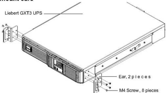
- Use M4 screws to install ears of accessories on both sides of the UPS, as shown in Figure 15.
Figure 15 Installing rack-mount ears
- Insert the UPS, with inner members attached, into bracket assemblies by inserting top and bottom edges of inner members into the top and bottom curved tracks of front members and sliding the UPS into the rack, as shown in Figure 16.
Figure 16 Insert the UPS


NOTE
Ends of inner members are tapered to allow the rear of the UPS to be angled upward before insertion, if space allows.
The UPS should move smoothly into the bracket assemblies. If not, recheck alignment of front and rear members from Steps 4 through 7.
-
Through the rack-mount ears, use M5 screws provided in this kit to secure the front of the UPS to the rack's vertical rails to prevent the UPS from sliding out of position.
-
If optional Liebert external battery cabinets will be connected to the UPS, they can be placed all on one side of the UPS or stacked beneath the UPS. The installation procedures are the same as those for the UPS.

NOTE
Up to four external battery cabinets can be connected to the Liebert GXT3. Each cabinet will increase the battery recharge time.
2.5 Cable Connection
The Liebert GXT3 rear panel has an input receptacle and output receptacles. Refer to 1.3.2 - Rear Panel Features for details. The battery cables are supplied with the battery cabinet.
2.5.1 Connecting to AC Mains and Loads

NOTE
Ensure that all the loads are turned off.
Prepare an input power supply that is properly protected by a circuit breaker in accordance with national and local electrical codes. The wall receptacle must be grounded.
Emerson recommends installing an upstream circuit breaker of the same series as the Liebert GXT3's input circuit breaker. The upstream breaker should have a higher capacity than the UPS input circuit breaker.
The specification of input circuit breaker on the rear panel of the UPS is given in Table 2.
Table 2 Specification of input circuit breaker
| Model | Rated Circuit Breaker |
| GXT3-700RT230 10A | |
| GXT3-1000RT230 10A | |
| GXT3-1500RT230 10A | |
| GXT3-2000RT230 16A | |
| GXT3-3000RT230 16A |
- Plug all loads into the output receptacles on the rear panel of the Liebert GXT3.

NOTE
- Do not overload any one output receptacle.
-
Output cable length should not exceed 10m (32.8 ft).
-
Plug the input receptacle of the Liebert GXT3 into the input power connection.
2.5.2 Connecting Battery Cables
- Switch Off the input breaker of the battery cabinet.
- Take out the battery cable included with the battery cabinet.
- Connect one end of the battery cable to the external battery connector on the rear panel of the UPS, and connect the other end to any battery port on the rear panel of the battery cabinet.
-
Switch On the battery breaker on the rear of the external battery cabinet.
-
Use the Configuration Program included with the UPS to specify the number of external battery cabinets connected to the Liebert GXT3. See Table 14 for approximate battery run times.
2.6 Connecting Communication Cables
Communication cable connection includes USB and option card cables.
2.6.1 Connecting USB Communication Cables
- Remove the USB communication cables from the accessories box.
- Insert one end of the USB communication cable to the USB port on the rear panel of the Liebert GXT3 (see Figure 2).
- Insert the other end of the USB communication cable to the USB port of the computer.
2.6.2 Installing the Optional Liebert IntelliSlot Card and Communication Cables
- Remove the protective cover of the Liebert IntelliSlot port on the Liebert GXT3 and set it aside.
- Insert the Liebert IntelliSlot card into the Liebert IntelliSlot port and secure it with screws.
- To connect any cable associated with a Liebert IntelliSlot card, refer to the user manual provided with the card.
To configure and use the Liebert IntelliSlot communication card, refer to the card's user manual.
Manuals for the various Liebert IntelliSlot cards are available at Liebert's Web site:
www.liebert.com
3.0 OPERATION AND DISPLAY PANEL
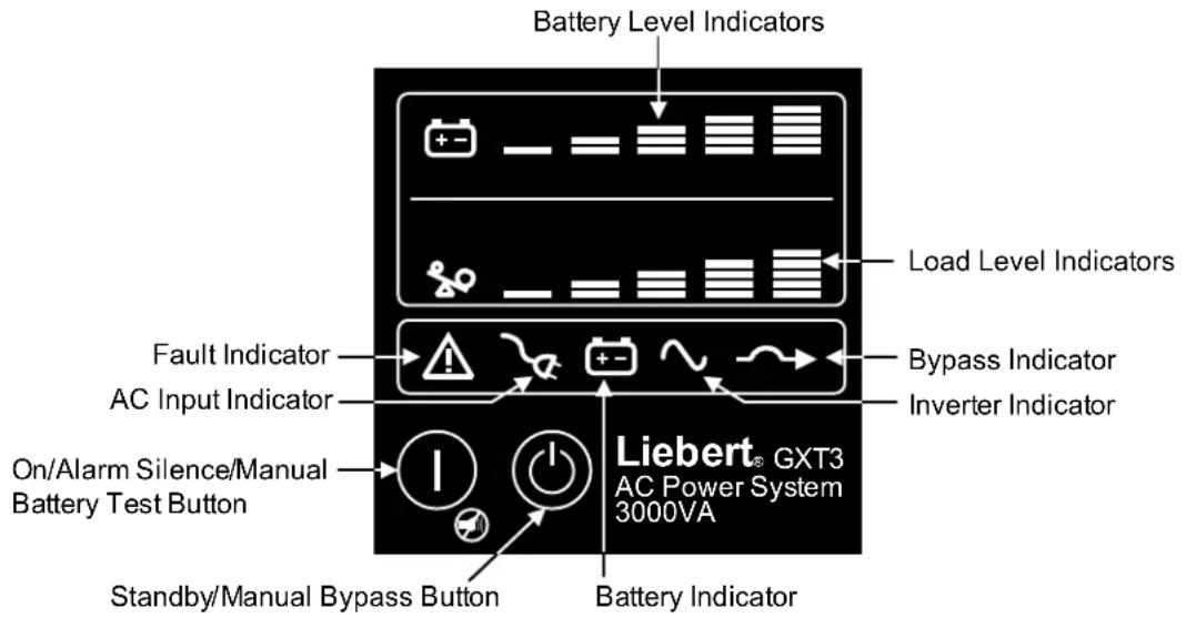
The operation and display panel, shown in Figure 17, is on the front panel of the Liebert GXT3 (see Figure 1).
Figure 17 Operation and display panel
3.1 Control Buttons
The operation and display panel has two control buttons: the On/Alarm Silence/Manual Battery Test button and the Standby/Manual Bypass button.
3.1.1 On/Alarm Silence/Manual Battery Test button
The On/Alarm Silence/Manual Battery Test button controls output power to connected load(s) and has three functions (see Table 3).
Table 3 Functions of the On/Alarm Silence/Manual Battery Test button
| Function Operation Description | ||
| ON Press the button once for 3 seconds To start up the UPS | ||
| Alarm silence1 | Press the button for at least half a second To silence alarms | 2 |
| Manual Battery Test | Press the button for at least half a second while operating in Mains (AC) Mode with no alarms present. | To initiate a manual battery test |
- The low battery and bypass reminder alarms cannot be silenced.
- After the alarm is silenced, UPS will reactivate the alarm system to alert of additional problems.
3.1.2 Standby/Manual Bypass button
The Standby/Manual Bypass button controls output power to connected load(s) and has two functions (see Table 4).
Table 4 Functions of the Standby/Manual Bypass button
| Function Operation Description | ||
| Manual Bypass | Press the button once and hold it for about 2 seconds.1 | To initiate a manual transfer of the connected loads to the internal bypass, if available |
| Standby | Press the button twice within four seconds while the UPS is in Manual Bypass or Battery Mode.2 | To shut down the UPS and shut Off all power to the connected loads |
- If the bypass is not available due to voltage or frequency, pressing this button once will be ignored.
- Perform all necessary shutdown procedures on connected loads before turning off the Liebert GXT3.
3.2 Indicators
The operation and display panel has seven indicators (see Figure 16). The indicators can be divided into two groups according to their applications: level indicators and UPS status indicators.
3.2.1 Level Indicators
Battery Level Indicators
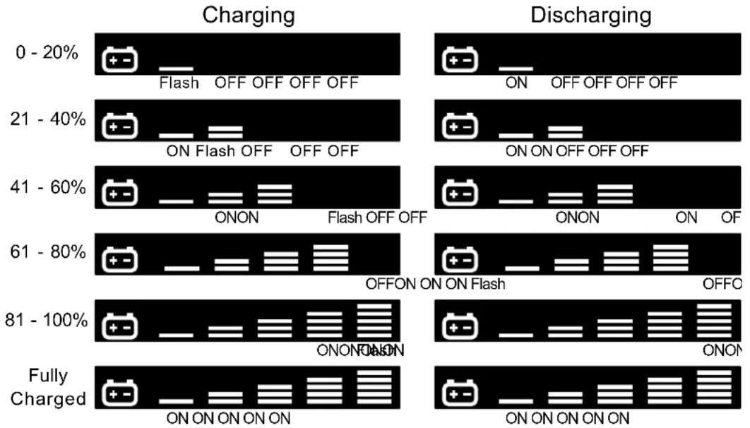
The battery level indicator is composed of five sets of LED bars that illuminate and flash to indicate the battery capacity level. The Liebert GXT3 battery capacity level is shown in 20% increments ( ±5% ). The battery level indicators will illuminate as shown in Figure 18.
Figure 18 Battery level indicators
bar
| Charge Range | Charging - ON | Charging - OFF | Discharging - ON | Discharging - OFF | Discharging - OFF | | ------------ | ------------- | -------------- | ---------------- | ----------------- | ----------------- | | 0 - 20% | +--- | +--- | +--- | +--- | +--- | | 21 - 40% | +--- | +--- | +--- | +--- | +--- | | 41 - 60% | +--- | +--- | +--- | +--- | +--- | | 61 - 80% | +--- | +--- | +--- | +--- | +--- | | 81 - 100% | +--- | +--- | +--- | +--- | +--- | | Fully Charged| +--- | +--- | +--- | +--- | +--- |Load Level Indicators
The load level indicator is composed of five sets of LED bars that illuminate to indicate the relative load on the UPS output in 25% increments ( ±5% ). The load level indicator will illuminate as shown in Figure 19.
Figure 19 Load level indicators

bar
| Range | ON | OFF | OFF OFF | |---|---|---|---| | 0 - 25% | ? | ? | ? | | 26 - 50% | ? | ? | ? | | 51 - 75% | ? | ? | ? | | 76 - 100% | ? | ? | ? | | Overload | ? | ? | ? | The visual data is not explicitly labeled in the image. The symbols inside the bars represent the 'ON' or 'OFF' states, but they are not explicitly labeled in the image. The numbers '0 - 25%' to 'Overload' likely denote percentage ranges. There is no explicit numerical values provided for the bars.3.2.2 UPS Status Indicators
UPS status is indicated by five symbols: fault indicator, AC input indicator, battery indicator, inverter indicator and bypass indicator. Table 5 shows the symbols and their meanings.
Table 5 UPS status indicators
| UPS Status Indicator Icon | Color Description | ||
Fault Indicator Red On if  has detected a fault; Off if there is no fault has detected a fault; Off if there is no fault | |||
AC input Indicator Green  | On when the mains input power is normal; Off during mains failure; flashing when mains power is outside specifications | ||
Battery Indicator Amber  | On when the battery is supplying power; Off when the battery is not supplying power | ||
Inverter Indicator Green  | On when the inverter is supplying power; Off when the inverter is not supplying power | ||
Bypass Indicator Amber  | On when the bypass is supplying power; Off when the bypass is not supplying power; flashing when mains power is outside specifications | ||
4.0 OPERATION
This section describes checks to be made before starting the UPS, how to start the UPS, manual battery test, manual bypass, shutting down the UPS and disconnecting the mains power from the UPS.

NOTE
The Liebert GXT3's battery has been fully charged before delivery, but some charge will be lost during storage and shipping. To ensure that the battery has adequate reserve power to protect the connected load, charge the battery for three hours before putting the UPS into service.
4.1 Startup Checklist for the Liebert GXT3
Before starting the UPS, perform these checks:
_ 1. Check that the input plugs and loads are connected properly and reliably.
____ 2. Check that the battery cable is connected properly.
3. Check that the communication cables are connected properly.
4.2 Starting the UPS
- Turn On the input circuit breaker (see Figure 2 for its position).
-
Turn On the UPS by pressing the On/Alarm Silence/Manual Battery Test button for three seconds.
After the button is pressed, the LEDs on the display will signal that the unit has initiated the startup process. -
Once the inverter LED has been illuminated, turn On the connected loads.
-
Check the status indicators to determine whether the Liebert GXT3 is operating normally.
-
Check the load level indicators to verify that the connected load does not exceed the UPS's rated capacity.
The UPS is now providing conditioned power to the loads.
4.3 Manual Battery Test
To initiate a manual battery test, press the On/Alarm Silence/Manual Battery Test button for at least half a second while operating from mains power with no alarm conditions present.
- If only the first two of the five LED segments illuminate, allow the UPS to recharge the batteries for 24 hours.
- Retest the batteries after 24 hours of charging.
• After the batteries have been retested, if only two of the five Battery LEDs illuminate, contact your local Emerson representative or Emerson Network Power Channel Support. - If none of the five Battery LEDs illuminate during a manual battery test, check the battery connection and allow the UPS to recharge the batteries for 1 hour, then initiate a manual battery test again.
- If none of the five Battery LEDs illuminate during the second manual battery test, replace batteries and contact your local Emerson representative or Emerson Channel Support.
4.4 Manual Bypass
Press the Standby/Manual Bypass button once while the UPS is in Mains (AC) Mode and hold it for about 2 seconds. The UPS will transfer the connected loads to the internal bypass. If the internal bypass is not available because of mains power problems, pressing this button once will be ignored. Bypass operation is indicated by an audible alarm and illuminated amber Bypass indicator. (If other indicators are illuminated, refer to 7.0 - Troubleshooting.)
4.5 Shut Down the Liebert GXT3
- Transfer the UPS to manual bypass by pressing the Standby/Manual Bypass button and holding it for about 2 seconds.
If manual bypass is not available, disregard the first step.
- Press the Standby/Manual Bypass button twice within four seconds to shut down the UPS. The UPS will shut down about 30 seconds after the button is pressed.
Power to the connected loads is now Off.
4.6 Disconnecting Input Power from the Liebert GXT3
- After the UPS has been shut down as detailed in 4.5 - Shut Down the Liebert GXT3, disconnect the input cable plug.
- Wait 30 seconds and verify that all indicators have turned Off and the fan has stopped; this indicates that the power-off is complete.
- Turn the external battery cabinet breaker switch to the Off position if the UPS has an external battery cabinet.
After powering off the UPS, the UPS ceases output and the load is powered Off.
5.0 COMMUNICATION
This section describes UPS communication over the three types of communication connections on the rear of the Liebert GXT3:
- Liebert IntelliSlot port
• USB port (standard B-type)
• Terminal Block Communication

CAUTION
To maintain safety (SELV) barriers and for electromagnetic compatibility, signal cables should be segregated and run separate from all other power cables.
5.1 Liebert IntelliSlot Communication Cards
The Liebert IntelliSlot port accepts three optional cards:
• Liebert IntelliSlot SNMP Card
• Liebert IntelliSlot Relay Card
• Liebert IntelliSlot 485 Card.
The Liebert IntelliSlot SNMP Card provides SNMP monitoring and control of the UPS across the network.
The Liebert IntelliSlot Relay Card provides dry contact relay outputs for custom-wired applications and delivers support for built-in shutdown for AS/400 systems.
The Liebert IntelliSlot 485 Card is used to connect the UPS and computer system.
Follow instructions provided with the Liebert IntelliSlot card to configure Liebert MultiLink, the UPS or any additional ancillary product for the Liebert GXT3. These instructions are available at:
multilink.liebert.com
5.1.1 Liebert MultiLink
Liebert MultiLink monitors the UPS continuously and can shut down the computer or server in the event of an extended power failure. Liebert MultiLink can also be configured to shut down the UPS.
Liebert MultiLink can also be configured for use without the USB cable when the Liebert IntelliSlot SNMP Card or Liebert IntelliSlot Web Card is installed in the UPS. An optional Liebert MultiLink License Kit permits shutting down the UPS over a network.
For more information about the Liebert IntelliSlot SNMP Card, Liebert IntelliSlot Web Card and Liebert MultiLink License Kits, visit the Liebert Web site (www.liebert.com) or contact your local Emerson representative.
5.2 USB Port Communication
The standard B-type USB port is used to connect the UPS and network server or other computer system using Liebert MultiLink. The configuration program can be completed through the communication port.
5.2.1 Configuration Program
Accessing the Configuration Program via USB is a new feature of the Liebert GXT3. For most users, the factory default settings will be adequate. This section illustrates the features available for modification, as well as the factory default setting.
The USB configuration program allows these features of the Liebert GXT3 to be changed:
- Enable/Disable Auto-Restart
- Select frequency converter operation with a fixed output frequency of 50Hz or 60Hz, bypass disabled
- Set the Low Battery Warning alarm time from 2 to 30 minutes
- Enable/Disable the Auto-Battery test
- Enable/Disable Auto-Restart after removing Remote shutdown
- Set the wiring mode of Remote shutdown
- Set the Auto-Enable output
- Set the Auto-Battery test to 7, 14, 21 or 28 days
- Select the number of external battery cabinets connected to the UPS to adjust the remaining run time calculated by Liebert software products
- Select one of multiple output voltages to match various voltages (see Table 6).
Table 6 Output voltage option, all models
| Factory Default Setting Output Voltage Option |
| 230VAC 220VAC, 230VAC and 240VAC |
NOTICE
The output voltage settings cannot be changed while the UPS is on and powering connected loads.

NOTE
Programming the output voltage of a 230V model of the Liebert GXT3 to 220V automatically derates the UPS to 96% of both the VA and Watt ratings (refer to 9.0 - Specifications for VA and Watt ratings).

NOTE
- This program is compatible with UPS models beginning with 'GXT3,' as in 'GXT3-3000RT230.' It is not compatible with earlier versions of the Liebert GXT UPS.
- A computer running Windows 2000 , XP or Vista is required to set up and run the configuration program.
5.3 Terminal Block Communication
The Terminal Block includes eight pins, as shown in Figure 20.
Figure 20 Terminal Block Communication pin layout

5.3.1 Any Mode Shutdown
The purpose of Any Mode Shutdown is to shut down the UPS output by turning Off the rectifier, inverter and static switch so that there is no power to the loads.
Any Mode Shutdown can be operated locally or remotely:
- Local Any Mode Shutdown can be performed by shorting Pin 1 and Pin 2.
- Remote Any Mode Shutdown can be performed using a switch connected to Pin 1 and Pin 2 and mounted at a remote location.

NOTE
Remote Power Off will be performed either by NO or NC contact of Any Mode Shutdown, depending on the settings in the configuration program.
A current-limited source for this optocoupler (+12VDC, 50mA) will be available from the UPS.
The connection to the UPS for remote connection will be via terminal block connector.
Any Mode Shutdown wiring must conform to all national, regional and local wiring regulations.

WARNING
When the Auto-Enable output option is selected and the UPS output is disabled using Pin 1 and Pin 2, the Liebert GXT3's output can turn On automatically and without warning if the Pin 1 and Pin 2 connection is changed.
5.3.2 Battery Mode Shutdown
Battery Mode Shutdown permits shutting down the UPS by turning off the rectifier, inverter and static switch so that there is no power to the load when the UPS is On Battery. The auxiliary power for the UPS will still be active.
Battery Mode Shutdown can be performed locally or remotely:
- Local Battery Mode shutdown can be performed by shorting Pin3 and Pin4.
- Remote Battery Mode Shutdown can be performed using a switch connected to Pin3 and Pin4 and mounted at remote location.

NOTE
Remote Power Off will be performed by NO contact.
A current-limited source for this optocoupler (+12VDC, 50mA) will be available from UPS.
The connection to the Liebert GXT3 for remote connection will be via terminal block connector.
Battery Mode Shutdown wiring must conform to all national, regional and local wiring codes and laws.
This signal must last for 1.5 seconds or longer.
A battery shutdown signal will not cause an immediate shutdown. It will start a 2-minute shutdown timer. This timer cannot be stopped once triggered. If the mains power returns during this countdown, the Liebert GXT3 will still shut down and must remain shut down for 10 seconds. Whether the UPS turns back on when the power is restored depends on the auto-restart setting.
5.3.3 On Battery
On Battery signal is a Normally Open (NO) dry contact. When the UPS is supplying output power from the battery this dry contact will be closed.
5.3.4 Low Battery
Low Battery signal is a Normally Open (NO) dry contact. When the UPS is supplying output power from the battery and has reached the Low Battery Warning time selected in the configuration program, this dry contact will be closed.

NOTE
The rated values for the dry contacts for the On Battery and Low Battery signals are:
- Rated Voltage: 5V
• Working Voltage Range: 4.5-10V
• Rated Current: 30ma
6.0 MAINTENANCE
This section describes replacing the internal battery pack, precautions, checking the Liebert GXT3's status and checking UPS functions.
6.1 Replacing the Internal Battery Pack
The Liebert GXT3 is designed to allow the user to replace the internal battery pack safely. Read the safety cautions before proceeding. Contact your local dealer or Emerson representative to obtain the part number and pricing of the appropriate replacement battery pack.
6.1.1 Battery Replacement Procedures
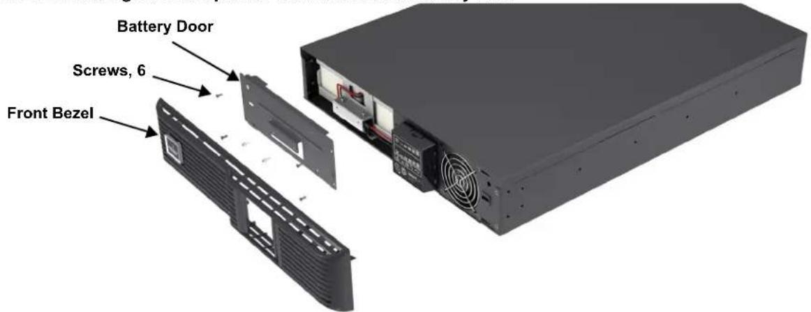
- Gently remove the front plastic bezel cover from the UPS.
- Loosen and remove the six screws on the battery door, as shown in Figure 21.
- Lay the battery door and screws aside for reassembly.
Figure 21 Removing the front plastic bezel cover and battery door
- Gently pull the battery wire out and disconnect the battery plug and battery receptacle, as shown in Figure 22.
Figure 22 Disconnecting the battery plug and battery connector (front view)

- Grasp the battery handle and pull the internal battery pack out of the UPS, as shown in Figure 23.
Figure 23 Pulling out the battery

- Unpack the new internal battery pack. Take care not to destroy the packing.
Compare the new and old internal battery packs to make sure they are the same type and model. If they are the same, proceed with Step 7; if they are different, stop and contact your local Emerson representative or Emerson Channel Support.
- Line up and slide in the new internal battery pack.
- Reconnect the battery plug and battery receptacle
- Gently push the battery wire and internal battery pack back into the UPS.
- Reattach the front battery door with the six screws.
- Reattach the front plastic bezel cover to the UPS.

NOTE
The internal battery pack is hot-swappable. However, caution should be exercised because during this procedure the load is unprotected from disturbances and power outages.
Do not replace the battery while the UPS is in Battery Mode. This will result in a loss of output power and will drop the connected load.
6.2 Battery Charging
The batteries are valve-regulated, nonspillable, lead acid and should be kept charged to attain their design life. The Liebert GXT3 charges the batteries continuously when it is connected to the mains input power.
If the Liebert GXT3 will be stored for a long time, Emerson recommends connecting the UPS to input power for at least 24 hours every four to six months to ensure full recharge of the batteries.

WARNING
The battery can present a risk of electrical shock and high short circuit current. The following precautions should be observed before replacing the battery pack:
- Remove rings, watches and other metal objects.
- Use tools with insulated handles.
- Do not lay tools or other metal objects on the batteries.
- If the battery kit is damaged in any way or shows signs of leakage, contact your local Emerson representative immediately.
- Do not dispose of batteries in a fire. The batteries may explode.
- Handle, transport and recycle batteries in accordance with local regulations.
6.3 Precautions
Although the Liebert GXT3 has been designed and manufactured to ensure personal safety, improper use can result in electrical shock or fire. To ensure safety, observe the following precautions:
- Turn Off and unplug the Liebert GXT3 before cleaning it.
- Clean the UPS with a dry cloth. Do not use liquid or aerosol cleaners.
- Never block or insert any objects into the ventilation holes or other openings of the UPS.
- Do not place the Liebert GXT3 power cord where it might be damaged.
6.4 Checking UPS Status
Emerson recommends checking the UPS operation status every six months.
- Check whether the UPS is faulty: Is the Fault Indicator on? Is the UPS sounding an alarm?
- Check whether the UPS is operating in Bypass Mode. Normally, the UPS operates in Normal Mode. If it is operating in Bypass Mode, stop and contact your local Emerson representative, or Emerson Channel Support.
- Check whether the battery is discharging. When the mains input is normal, the battery should not discharge. If the UPS is operating in Battery Mode, stop and contact your local Emerson representative or Emerson Channel Support.
6.5 Checking UPS Functions

NOTE
UPS function check procedures may interrupt power supply to the connected load.
Emerson recommends checking the UPS functions once every six months.
Back up the load data before conducting the UPS functions check. Procedures are as follows:
- Press the Standby/Manual Bypass button to check whether the buzzer and indicators are normal.
- Press the On/Alarm Silence/Manual Battery Test button to check again whether the indicators are on and the UPS is operating normally.
- Press the On/Alarm Silence/Manual Battery Test button for three seconds after Inverter Mode. The UPS should initiate a battery self-test. Check to determine whether the battery is operating normally. If not, stop and contact your local Emerson representative or Emerson Channel Support
7.0 TROUBLESHOOTING
This section indicates various UPS symptoms a user may encounter and provides a troubleshooting guide in the event the UPS develops a problem. Use the following information to determine whether external factors caused the problem and how to remedy the situation.
7.1 UPS Symptoms
The following symptoms indicate the Liebert GXT3 is malfunctioning:
- The relative indicators illuminate, indicating the UPS has detected a problem.
- An alarm buzzer sounds, alerting the user that the UPS requires attention.
7.1.1 Indicators
In addition to the fault indicator being illuminated, one or more of LED segments of battery level indicator will also be illuminated to provide a diagnostic aid to the user, as shown in Figure 24. The descriptions are listed in Table 7.
Figure 24 Battery level indicator

Table 7 Indicator descriptions
| Indicator Diagnosis/Audible alarm | |
| A - E On bypass from output overload (half-second beep every half second) | |
| A On bypass due to overtemperature condition (1-second beep every 4 seconds) | |
| B On bypass due to DC bus overvoltage (1-second beep every 4 seconds) | |
| C | On bypass due to DC/DC power supply failure (1-second beep every 4 seconds) |
| D PFC failure (1-second beep every 4 seconds). | |
| E On bypass due to inverter failure (1-second beep every 4 seconds) | |
| A&C UPS failed battery test (2-second beep every 60 seconds) | |
| C&E | UPS shutdown by command from communication (USB port or Liebert IntelliSlot port) (no audible) |
| A&B | UPS Failure (includes dual-fan failure, single-fan failure under certain conditions and battery charger failure) and continuous alarm |
| Battery Indicator Flashing | Internal Battery source not available (continuous horn); check battery connection, power down and reboot UPS. |
| Bypass Indicator Flashing | Mains power voltage or frequency is out of tolerance; bypass is unavailable |
A - E indicators are shown in Figure 24. If the UPS experiences an overload, the UPS will transfer from bypass back to inverter approximately 5 minutes after the overload condition ends.
7.1.2 Audible Alarm
An audible alarm will sound in conjunction with the visual indicators to indicate a change in UPS operating status. The audible alarm will sound as described in Table 8.
Table 8 Audible alarm description
| Condition Alarm | |
| Battery discharge Half-second beep every 10 seconds | |
| Low battery Two half-second beeps every 5 seconds | |
| UPS fault, load on bypass 1-second beep every 4 seconds | |
| UPS fault, no power to load Continuous | |
| Overload Half-second beep every half second | |
| Battery replacement 2-second beep every 60 seconds | |
| Battery loss Continuous | |
| Wiring problem (loss of proper grounding for UPS) Continuous | |
| Bypass reminder | 1-second beep every 2 minutes |
7.2 Troubleshooting
In the event of an issue with the UPS, refer to Table 9 to determine the cause and solution. If the fault persists, contact Emerson Channel Support.
Table 9 Troubleshooting table
| Problem | Cause | Solution |
| UPS fails to start when the On/Alarm Silence/Manual Battery Test button is pressed | UPS is short-circuited or overloaded | Ensure UPS is Off. Disconnect all loads and ensure nothing is lodged in output receptacles. Ensure loads are not defective or shorted internally. |
| Battery indicator is illuminated | UPS is not plugged in | UPS is operating from battery mode. Ensure UPS is securely plugged into the wall receptacle. |
| UPS input protection fuse has blown/opened | UPS is operating from battery mode. Save data and close applications. Replace UPS input fuse, then restart UPS. | |
| Mains power is out of tolerance | UPS is operating from battery mode. Save data and close applications. Ensure mains supply voltage is within acceptable limits for UPS. | |
| UPS has reduced battery backup time | Batteries are not fully charged | Keep UPS plugged in continuously at least 24 hours to recharge batteries. |
| UPS is overloaded | Check load level indicator and reduce the load on the UPS. | |
| Batteries may not be able to hold a full charge due to age | Replace batteries. Contact your local dealer, Emerson representative or Emerson Channel Support for replacement battery kit. | |
| Fault and Bypass indicators and all LED segments of battery level indicator are illuminated | UPS is overloaded or load is faulty | Check load level indicator and remove non-essential loads. Recalculate the load and reduce number of loads connected to UPS. Check load for faults. |
| Fault and Bypass indicators and diagnostic A indicator are illuminated | UPS has been shut down due to temperature condition; load is on bypass power | Ensure UPS is not overloaded, ventilation holes are not blocked and room ambient temperature is not excessive. Wait 30 minutes to allow UPS to cool, then restart UPS. If UPS cannot restart, contact your local dealer, Emerson representative or Emerson Channel Support. |
| Fault and Bypass indicators and diagnostic B indicator are illuminated | UPS internal DC bus overvoltage | UPS requires service. Contact your local dealer, Emerson representative or Emerson Channel Support. |
| Problem Cause Solution | ||
| Fault and Bypass indicators and diagnostic C indicator are illuminated | UPS DC/DC fault | UPS requires service. Contact your local dealer, Emerson representative or Emerson Channel Support. |
| Fault indicator and diagnostic D indicator are illuminated | UPS PFC (Power Factor Correction Circuit) fault | UPS requires service. Contact your local dealer, Emerson representative or Emerson Channel Support. |
| Fault and Bypass indicators and diagnostic E indicator are illuminated | UPS inverter fault | UPS requires service. Contact your local dealer, Emerson representative or Emerson Channel Support. |
| Fault indicator and diagnostic A and C indicators are illuminated | UPS failed the battery test | Replace batteries. Contact your local dealer, Emerson representative or Emerson Channel Support. |
| Fault and Bypass indicators and diagnostic C and E indicators are illuminated | UPS has been shut down by a command from the communications port(s) | Your UPS has received a signal or command from the attached computer. If this was inadvertent, ensure the communication cable used is correct for your system. For assistance, contact your local dealer, Emerson representative or Emerson Channel Support. |
| Fault indicator and diagnostic A and B indicators are illuminated | UPS failure (includes dual-fan failure, single-fan failure under certain conditions and battery charger failure) and continuous alarm | Ensure fan is not blocked up. If the fault is not removed, contact your local dealer, Emerson representative or Emerson Channel Support. |
| AC input indicator is flashing. | UPS detected a line-to-neutral reversal or a loss of proper grounding for UPS; continuous horn and UPS cannot start up in standby status. This is active only when power is first applied to the input. Once the UPS is running, the AC input indicator will flash, unless the input wiring is correctly changed. | Contact a qualified electrician to verify site wiring. |
| Battery indicator is flashing. | Battery source is not available; continuous horn. | Check battery connections, completely power down and restart UPS.NOTE: If the battery circuit opens while the UPS is running, it will be detected when the next battery test is performed. |
| Bypass indicator is flashing. | Because the voltage or frequency is outside acceptable limits, the bypass is disabled. | The AC input powers the PFC input and serves as the bypass source. If the AC is present but the voltage or frequency exceeds the acceptable range for safe operation with a load, the bypass will be disabled and this indicator will flash, indicating that the bypass is unavailable. |
When reporting a UPS issue to Emerson, include the UPS model and serial number. These are on the top panel of the Liebert GXT3.
8.0 BATTERY CABINET
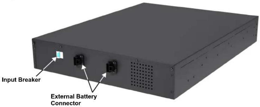
Optional battery cabinets are available for the Liebert GXT3. The external battery connector and input breaker are on the battery cabinet's rear panel, as shown in Figure 25. For battery cabinet specifications, refer to Table 12.
Figure 25 Battery cabinet

WARNING
Do not contact the external battery connector and ground without wearing protective gloves and clothing and taking other precautions against electrical shock. The battery loop and AC input are not insulated, which may cause a dangerous voltage between the external battery connector and ground.

NOTE
The length of the standard battery cable delivered with the battery cabinet is 0.65m (2.13ft).
9.0 SPECIFICATIONS
The specifications of the Liebert GXT3 are listed in Table 10 and Table 11.
Table 10 Specifications of GXT3-700RT230 and GXT3-1000RT230 UPS
| Parameters | Product model | |
| GXT3-700RT230 GXT3-1000RT230 | ||
| Model Rating 700VA/630W 1000VA/900W | ||
| Dimensions, D x W x H, mm (in) | ||
| Unit | 497 x 430 x 85(19.6 x 16.9 x 3.3) | |
| Shipping | 617 x 570 x 262(24.3 x 22.4 x 10.3) | |
| Weight, kg (lb) | ||
| Unit | 16.8 (37) | |
| Shipping | 20 (44) | |
| Input AC | ||
| Voltage Range (typical) | 230VAC nominal; variable based on output load | |
| 90% ~ 100% loading | 177VAC/280VAC | |
| 70% ~ 90% loading | 168VAC/280VAC | |
| 30% ~ 70% loading | 150VAC/280VAC | |
| 0 ~ 30% loading | 115VAC/280VAC | |
| Frequency | 40Hz ~ 70Hz; Auto Sensing | |
| Input Power Receptacle | C14 | |
| Output AC | ||
| Output Receptacles | C13 x 6 | |
| Voltage | 220/230/240VAC (user configurable); ±3% | |
| Frequency | 50Hz or 60Hz | |
| Waveform | Sine wave | |
| Mains (AC) Mode Overload | 200% for 2 seconds; 150% for 1 minute with transfer to bypass | |
| Battery | ||
| Type | Valve-regulated, nonspillable, lead acid | |
| Qty x Vx Rating | 4 x 12V x 5.0Ah | |
| Battery Mfr/Part# | YUASA/NPH5-12; CSB/ HR 1221W | |
| Backup Time | See Table 14 - Battery run times | |
| Recharge Time | 3 hours to 90% capacity after full discharge with 100% load till UPS auto-shutdown (Internal Batteries Only) | |
| Environmental Requirements | ||
| Operating Temp | 0°C to +40°C (+32°F to +104°F); Table 13 - Operating temperature parameters | |
| Storage Temp | -15°C to +50°C (5°F to 122°F) | |
| Relative Humidity | 0%RH to 95%RH, non-condensing | |
| Operating Elevation | Up to 3000m (10,000 ft.) at 40°C (104°F) without derating | |
| Storage Elevation | 15,240 (50,000 ft.) maximum | |
| Audible Noise | < 46 dBA, at 1 meter (3.2ft) from the rear< 43 dBA, at 1 meter (3.2ft) from the front or sides | |
| Agency | ||
| Safety | EC/EN/AS 62040-1-1:2008 | |
| RFI/EMI | IEC/EN/AS 62040-2 2nd Ed =CISPR22 Class A | |
| Surge Immunity | IEC 62040-2 2nd Ed | |
| Transportation | ISTA Procedure 1A | |
Table 11 Specifications of the Liebert GXT3-1500RT230, GXT3-2000RT230 and GXT3-3000RT230
| Parameters | Product model | ||
| GXT3-1500RT230 GXT3-2000RT230 GXT3-3000RT230 | |||
| Model Rating 1500VA/1350W 2000VA/1800W 3000VA/2700W | |||
| Dimensions, D x W x H, mm (in) | |||
| Unit | 497 x 430 x 85(19.6 x 16.9 x 3.3) | 602 x 430 x 85(23.7 x 16.9 x 3.3) | |
| Shipping | 617 x 570 x 262(24.3 x 22.4 x 10.3) | 717 x 570 x 262(28.2 x 22.4 x 10.3) | |
| Weight, kg (lb) | |||
| Unit | 23.2 (51.1) 28 (61.7) 28 (61.7) | ||
| Shipping | 26 (57.3) 24 (52.9) 32 (70.5) | ||
| Input AC | |||
| Voltage Range (typical) | 230VAC nominal; variable based on output load | ||
| 90% ~ 100% loading | 177VAC/280VAC 196VAC/280VAC | ||
| 70% ~ 90% loading | 168VAC/280VAC 184VAC/280VAC | ||
| 30% ~ 70% loading | 150VAC/280VAC 161VAC/280VAC | ||
| 0 ~ 30% loading | 115VAC/280VAC 115VAC/280VAC | ||
| Frequency | 40Hz ~ 70Hz; Auto Sensing | ||
| Input Power Receptacle | C14 | C20 | |
| Output AC | |||
| Output Receptacles | C13 x 6 | C13 x 6; C19 x 1 | |
| Voltage | 220/230/240VAC (user configurable); ±3% | ||
| Frequency | 50Hz or 60Hz | ||
| Waveform | Sine wave | ||
| Mains (AC) Mode Overload | 200% for 2 seconds; 150% for 50 seconds | 200% for 2 seconds;150% for 55 seconds | |
| Battery | |||
| Type | Valve-regulated, nonspillable, lead acid | ||
| Qty x Vx Rating | 4 x 12V x 7.2Ah | 4 x 12V x 9.0Ah 6 x | 12V x 9.0Ah |
| Battery Mfr/Part# | Panasonic/UP-RW1236CSB/ GP 1272 | Panasonic/UP-RW1245CSB/ HR 1234W F2 | |
| Backup Time | See Table 14 - Battery run time | ||
| Recharge Time | 3 hours to 90% capacity after full discharge with 100% load till UPS auto-shutdown(Internal Batteries Only) | ||
| Environmental Requirements | |||
| Operating Temp | 0°C to 40°C (32°F to 104°F); Table 13 - Operating temperature parameters | ||
| Storage Temp | -15°C to +50°C (5°F to 122°F) | ||
| Relative Humidity | 0%RH to 95%RH, non-condensing | ||
| Operating Elevation | Up to 3000m (10,000 ft.) at 40°C (104°F) without derating | ||
| Storage Elevation | 15000m (50,000 ft.) maximum | ||
| Audible Noise | < 45 dBA max. at 1 meter (3.2ft.) front and side< 46 dBA, at 1 meter (3.2ft.) rear | < 48 dBA max. at 1 meter (3.2ft.) front and side< 48 dBA, at 1 meter (3.2ft.) rear | |
| Agency | |||
| Safety | EC/EN/AS 62040-1-1:2008 | ||
| RFI/EMI | IEC/EN/AS 62040-2 2nd Ed =CISPR22 Class A | ||
| Surge Immunity | IEC 62040-2 2nd Ed | ||
| Transportation | ISTA Procedure 1A | ||
Table 12 Battery cabinet specifications
| Parameter | Model Number | |
| GXT3-48VBATT GXT3-72VBATT | ||
| Used w/UPS Model | GXT3-700RT230, GXT3-1000RT230, GXT3-1500RT230, GXT3-2000RT230 | GXT3-3000RT230 |
| Dimensions, D x W x H, mm (in) | ||
| Unit | 497 × 430 × 85(19.7 x 16.9 x 3.3) | 602 × 430 × 85(23.6 x 16.9 x 3.3) |
| Shipping | 617 x 570 x 262(24.3x 22.4 x 10.3) | 717 x 570 x 262(28.2 x 22.4 x 10.3) |
| Weight, kg (lb) | ||
| Unit | 32 (70.5) 42 (92.6) | |
| Shipping | 35 (77.2) 46 (101.4) | |
| Battery parameters | ||
| Type | Valve-regulated, nonspillable, lead acid | |
| Qty × V× Rating | 2 × 4 × 12V × 9.0Ah 2 × 6 × 12V × 9.0Ah | |
| Battery Mfr/Part# | Panasonic/UP-RW1245 CSB/HR 1234W F2 | |
| Backup Time | See Table 14 - Battery run times | |
| Environmental | ||
| Operating Temperature | 0°C to 40°C (32°F to 104°F) | |
| Storage Temperature | -15°C to +40°C (19°F to 104°F) | |
| Relative Humidity | 0% to 95%, non-condensing | |
| Operating Elevation | Up to 3000m (10,000 ft.) at 104°F (40°C) without derating | |
| Storage Elevation | 15000m (50,000 ft.) maximum | |
| Agency | ||
| Safety | EC/EN/AS 62040-1-1:2008 | |
| RFI/EMI | FCC Part 15, Class A=CISPR22 Class B | |
| Surge Immunity | EC 62040-2 2nd Ed | |
| Transportation | ISTA Procedure 1A | |
Table 13 Operating temperature parameters
| Ambient Temperature, °C (°F) | 25-30 (77-86) | 30-35 (86-95) | 35-40 (95-104) |
| Maximum Output Power Factor Derating @ Maximum Load | 100%-93% | 93%-86% | 86%-79% |
Table 14 Battery run times
| Number of Batteries/Cabinets | Load, % of Capacity | Run Time, Minutes | ||||
| 700VA | 1000VA | 1500VA | 2000VA | 3000VA | ||
| Internal Battery | 10% 115 84 109 | 73 73 | ||||
| 20% 57 42 46 33 | 34 | |||||
| 30% 39 28 27 21 | 21 | |||||
| 40% 29 20 19 14 | 14 | |||||
| 50% 24 14 13 11 | 11 | |||||
| 60% 19 11 10 8 9 | ||||||
| 7 0 | % | 1 | 5 | 9 | ||
| 8 0 | % | 1 | 2 | 8 | ||
| 9 0 | % | 1 | 0 | 6 | ||
| 100% 9 | 5 4 4 4 | |||||
| Internal Battery + 1 External Battery Cabinet | 10% | 529 | 386 | 315 | 252 | 252 |
| 20% | 284 | 212 | 147 | 117 | 120 | |
| 30% 194 | 129 96 78 | 78 | ||||
| 40% 139 98 67 58 | 57 | |||||
| 50% 111 75 50 43 | 43 | |||||
| 60% 93 59 39 35 | 35 | |||||
| 70% 77 50 33 28 | 29 | |||||
| 80% 66 42 27 25 | 25 | |||||
| 90% 56 35 23 21 | 22 | |||||
| 100% 50 32 20 19 | 19 | |||||
| Internal Battery + 2 External Battery Cabinets | 10% | 1110 | 765 | 576 | 467 | 467 |
| 20% | 524 | 383 | 283 | 227 | 227 | |
| 30% | 380 | 265 | 182 | 141 | 141 | |
| 40% 281 | 197 123 98 | 98 | ||||
| 50% 230 | 142 97 80 | 80 | ||||
| 60% 189 | 115 80 66 | 66 | ||||
| 70% 149 97 66 54 | 55 | |||||
| 80% 125 86 55 46 | 46 | |||||
| 90% 108 76 48 40 | 41 | |||||
| 100% 97 67 42 36 | 36 | |||||
| Internal Battery + 3 External Battery Cabinets | 10% | 1522 | 1136 | 790 | 681 | 681 |
| 20% | 895 | 584 | 406 | 321 | 321 | |
| 30% | 560 | 388 | 263 | 217 | 217 | |
| 40% | 389 | 305 | 196 | 148 | 148 | |
| 50% | 345 | 238 | 147 | 110 | 110 | |
| 60% 287 | 188 114 89 | 91 | ||||
| 70% 242 | 157 96 80 | 80 | ||||
| 80% 208 | 128 86 70 | 70 | ||||
| 90% 165 | 110 75 61 | 62 | ||||
| 100% | 156 96 65 | 55 55 | ||||
| Internal Battery + 4 External Battery Cabinets | 10% 1991 1488 | 1104 994 995 | ||||
| 20% 1208 880 567 | 467 467 | |||||
| 30% 822 553 348 | 285 285 | |||||
| 40% 550 380 271 | 206 206 | |||||
| 50% 460 315 209 | 163 163 | |||||
| 60% 360 263 165 | 120 120 | |||||
| 70% 317 215 128 | 101 104 | |||||
| 80% 280 185 113 | 88 88 | |||||
| 90% 247 161 96 | 80 81 | |||||
| 100% 219 137 87 | 74 74 | |||||
9.1 Product Warranty Registration
To register for warranty protection, visit the Quick Links section of the Liebert Web site at:
http://www.liebert.com
Click on Product Warranty Registration and fill in the form.
If you have any questions, contact Emerson Channel Applications Engineering at:
North America: 800-222-5877
Outside North America: 00-800-1155-4499
liebert.upstech@emerson.com
Ensuring The High Availability Of Mission-Critical Data And Applications.
Emerson Network Power, a business of Emerson (NYSE:EMR), is the global leader in enabling Business-Critical Continuity™ from grid to chip for telecommunication networks, data centers, health care and industrial facilities. Emerson Network Power provides innovative solutions and expertise in areas including AC and DC power and precision cooling systems, embedded computing and power, integrated racks and enclosures, power switching and controls, infrastructure management, and connectivity. All solutions are supported globally by local Emerson Network Power service technicians. Liebert AC power, precision cooling and monitoring products and services from Emerson Network Power deliver Efficiency Without Compromise™ by helping customers optimize their data center infrastructure to reduce costs and deliver high availability.
Technical Support / Service
Web Site
www.liebert.com
Monitoring
liebert.monitoring@emerson.com
800-222-5877
Outside North America: +00800 1155 4499
Single-Phase UPS & Server Cabinets
liebert.upstech@emerson.com
800-222-5877
Outside North America: +00800 1155 4499
Three-Phase UPS & Power Systems
800-543-2378
Outside North America: 614-841-6598
Environmental Systems
800-543-2778
Outside the United States: 614-888-0246
Locations
United States
1050 Dearborn Drive
P.O. Box 29186
Columbus, OH 43229
Europe
Via Leonardo Da Vinci 8
Zona Industriale Tognana
35028 Piove Di Sacco (PD) Italy
+39 049 9719 111
Fax: +39 049 5841 257
Asia
29/F, The Orient Square Building
F. Ortigas Jr. Road, Ortigas Center
Pasig City 1605
Philippines
+63 2 687 6615
Fax: +63 2 730 9572
While every precaution has been taken to ensure the accuracy
and completeness of this literature, Liebert Corporation assumes no
responsibility and disclaims all liability for damages resulting from use of
this information or for any errors or omissions.
© 2009 Liebert Corporation
All rights reserved throughout the world. Specifications subject to change
without notice.
® Liebert is a registered trademark of Liebert Corporation.
All names referred to are trademarks
or registered trademarks of their respective owners.
SLI-23180_REV1_08-10
Emerson Network Power.
The global leader in enabling Business-Critical Continuity ™

AC Power

Embedded Computing

Outside Plant
EmersonNetworkPower.com

Racks & Integrated Cabinets

Services

Surge Protection

Connectivity
Embedded Power

Power Switching & Controls

DC Power

Infrastructure Management & Monitoring

Precision Cooling

- TABLE OF CONTENTS
- IMPORTANT SAFETY PRECAUTIONS ....1
- SAVE THESE INSTRUCTIONS ....1
- GLOSSARY OF SYMBOLS....3
- PRODUCT DESCRIPTION 4
- INSTALLATION 9
- OPERATION AND DISPLAY PANEL....17
- OPERATION 20
- COMMUNICATION 22
- MAINTENANCE 26
- TROUBLESHOOTING 29
- BATTERY CABINET....32
- SPECIFICATIONS....33
- Product Warranty Registration.... 37
- FIGURES
- TABLES
- WARNING
- SAVE THESE INSTRUCTIONS
- UPS Safety Notes
- Battery Safety
- CAUTION
- Information for the Protection of the Environment
- GLOSSARY OF SYMBOLS
- PRODUCT DESCRIPTION
- Features
- Available Models
- Appearance and Components
- Appearance
- Rear Panel Features
- Major Components
- Transient Voltage Surge Suppression (TVSS) and EMI/RFI Filters
- Rectifier/Power Factor Correction (PFC) Circuit
- Inverter
- Battery Charger
- DC-to-DC Converter
- Battery
- Dynamic Bypass
- NOTE
- Operating Mode
- Mains (AC) Mode
- Manual Bypass Mode
- NOTICE
- Battery Mode
- Battery Recharge Mode
- Frequency Converter Mode
- INSTALLATION
- Unpacking and Inspection
- What's Included
- With GXT3 UPS
- Preparation for Installation
- Installation Environment
- Installation Clearances
- Mechanical Installation
- Tower Installation
- Rack Installation
- Cable Connection
- Connecting to AC Mains and Loads
- Connecting Battery Cables
- Connecting Communication Cables
- Connecting USB Communication Cables
- Installing the Optional Liebert IntelliSlot Card and Communication Cables
- OPERATION AND DISPLAY PANEL
- Control Buttons
- On/Alarm Silence/Manual Battery Test button
- Standby/Manual Bypass button
- Indicators
- Level Indicators
- Battery Level Indicators
- Load Level Indicators
- UPS Status Indicators
- OPERATION
- Startup Checklist for the Liebert GXT3
- Starting the UPS
- Manual Battery Test
- Manual Bypass
- Shut Down the Liebert GXT3
- Disconnecting Input Power from the Liebert GXT3
- COMMUNICATION
- Liebert IntelliSlot Communication Cards
- Liebert MultiLink
- USB Port Communication
- Configuration Program
- Terminal Block Communication
- Any Mode Shutdown
- Battery Mode Shutdown
- On Battery
- Low Battery
- MAINTENANCE
- Replacing the Internal Battery Pack
- Battery Replacement Procedures
- Battery Charging
- Precautions
- Checking UPS Status
- Checking UPS Functions
- TROUBLESHOOTING
- UPS Symptoms
- Indicators
- Audible Alarm
- Troubleshooting
- BATTERY CABINET
- SPECIFICATIONS
- Product Warranty Registration
- Ensuring The High Availability Of Mission-Critical Data And Applications.
- Technical Support / Service
- Web Site
- Monitoring
- Single-Phase UPS & Server Cabinets
- Three-Phase UPS & Power Systems
- Environmental Systems
- Locations
- United States
- Europe
- Asia
- Emerson Network Power.
- EmersonNetworkPower.com
Brand : Emerson
Model : Liebert GXT3 1500VA
Category : Uninterruptible power supply