
Liebert XDFN - Computer Cooling System Emerson - Free user manual and instructions
Find the device manual for free Liebert XDFN Emerson in PDF.


| Product Type | Precision Cooling System for IT Racks |
| Brand | Emerson (Liebert) |
| Model Series | Liebert XDFN |
| Cooling Capacities (DX) | 13, 17, 20, 23 kW |
| Cooling Capacity (CW) | 25 kW |
| Air Distribution | Downflow |
| Fan Type | EC fan (3-phase, 400V) |
| Power Supply (Cooling Module) | 400 V / 3 Ph / 50 Hz |
| Power Supply (Rack Module) | 230 V / 1 Ph / 50 Hz |
| Refrigerant Options | R407C (standard), R22 |
| Humidification | Optional electrode humidifier (HUMIDAIR) |
| Monitoring | Optional SNMP |
| Fire Detection & Extinguishing | Optional (smoke detector, extinguishing system) |
| Width (Cooling Module) | 750 mm |
| Depth (Cooling Module) | 1240 mm (all-height doors), 1200 mm (short doors) |
| Height (Cooling Module) | 2400 mm |
| Weight (Cooling Module, approx) | 413 - 455 kg (depending on model) |
| Width (Rack Module) | 850 mm |
| Depth (Rack Module) | 1240 mm (all-height doors), 1200 mm (short doors) |
| Height (Rack Module) | 2400 mm |
| Weight (Rack Module, approx) | 319 kg |
| Noise Level | < 60 dBA at 2 m |
| Operating Temperature Range | 18°C - 28°C, 40% - 50% RH |
| Indoor/Outdoor Limits (DX) | Outdoor: -20°C to +45°C (with condensing control) |
| Maintenance | Monthly to yearly schedule; filters, fans, coils, refrigeration circuit checks |
Frequently Asked Questions - Liebert XDFN Emerson
User questions about Liebert XDFN Emerson
0 question about this device. Answer the ones you know or ask your own.
Ask a new question about this device
Download the instructions for your Computer Cooling System in PDF format for free! Find your manual Liebert XDFN - Emerson and take your electronic device back in hand. On this page are published all the documents necessary for the use of your device. Liebert XDFN by Emerson.
USER MANUAL Liebert XDFN Emerson
Closed Loop Cooling for High Density Racks
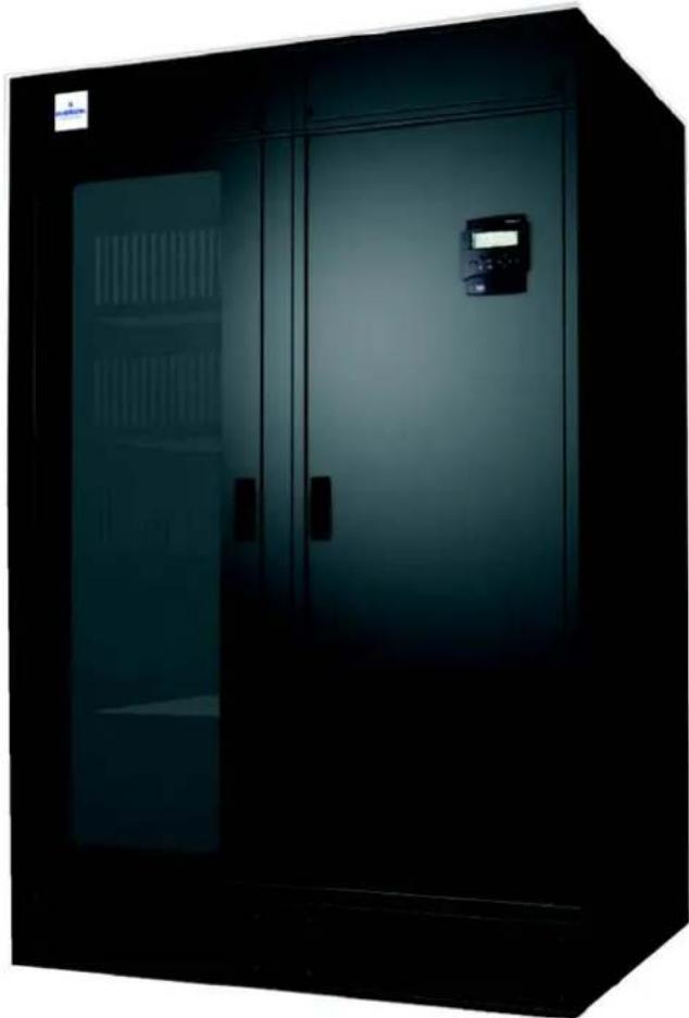
natural_image
Exterior view of a dark industrial cabinet with two doors and a digital display unit (no visible text or symbols)SERVICE MANUAL
| English | Cod. 272823 | Rev. 28.03.2008 |

Caution
We recommend that:
•the manual is retained for the entire service life of the machine;
•the user reads the manually carefully before carrying out any operations on the machine;
- the control is used exclusively for the purpose for which it is intended; incorrect use of the control shall release the manufacturer from any liability.
This manual has been prepared to enable the end-user to carry out only the operations that can be made with the panels closed. Any operations that require the opening of doors or equipment panels must be carried out only by qualified personnel.
Each machine is equipped with an Electric Insulating device which allows the operator to work in conditions of safety. Switch off the machine with this electric insulating device before any maintenance operation to eliminate risks remaining (electric shocks, burns, automatic restarting, moving parts and remote control).
The panel key supplied with the unit must be kept by the person responsible for maintenance.
For identification of the unit (model and serial no.) in case of the necessity for assistance or spare parts, locate the identification label on the outside of the unit.

Liebert.
Attention: data relevant to the unit are indicated on the inboard below empty fac—simile).
Data in the manual are referred to standard conditions and can be modified without any advance notice.
POS. DESCRIPTION
1 Compressor Full Load Ampere [A]
2 Compressor Locked Rotor Ampere [A]
3 Compressor quantity
4 Evaporator fan Full Load Ampere [A]
5 Evaporator fan Locked Rotor Ampere [A]
6 Evaporator fan quantity
7 Condenser fan Full Load Ampere [A]
8 Condenser fan Locked Rotor Ampere [A]
9 Condenser fan quantity
10 Electrical heating Ampere
11 Electrical heating steps
12 Humidifier Ampere
13 Steam production capacity
14 Max. unit AC Ampere
15 Max. unit DC Ampere
16 Rated peak withstand current
17 Rated short-time current
18 Refrigerant type
19 High pressure switch Stop
20 High pressure switch Restart
21 Low pressure switch Stop
22 Low pressure switch Restart
23 Min. indoor air temperature
24 Max. indoor air temperature
25 Min. indoor air rel. humidity
26 Max. indoor air rel. humidity
27 Max. refrigeration circuit pressure
Digit Configuration
The user will configure the system choosing in between the following alternatives. The basic system is composed by six pieces to be precisely defined:
a. Air conditioner
b. Base module air conditioner
c. Top plenum air conditioner
d. Rack
e. Base module rack
f. Top plenum rack

Air conditioner
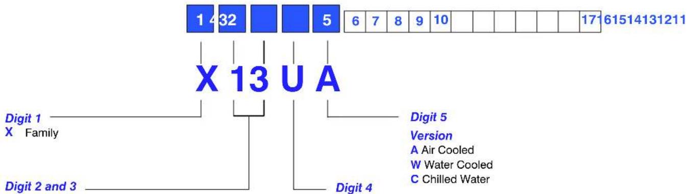
Size:
Cooling Capacity
"kW" (approx) 13, 17, 20, 23 as DX; 25 as CW
Air distribution
U Downflow
Digit 6 - Fan
1 EC fan
Digit 7 – Main Power Supply
0 400 V/3 Ph/50 Hz
Digit 8 - Front door and base module
S All height door, damper on left side
D All height door, damper on right side
E All height door, damper on both sides
L Short door, base module with damper on left side
R Short door, base module with damper on right side
2 Short door, base module with damper on both sides
0 Short door, without base module
Digit 9 – Humidification
0 None
V Electrode humidifier
Digit 10 - Cooling module configuration
B Basic cooling
R Redundant cooling
Digit 11 - Monitoring
0 None
1 Via SNMP
Digit 12 - Top plenum
1 With top plenum
0 Without top plenum
Digit 13 - Refrigerant
0 R407C (and with CW unit)
1 R22
Digit 14 – Fire detection and extinguishing
0 None
1 Fire extinguishing, one bottle
2 Fire extinguishing, two bottles
Digit 15 - Condensing control
A Condensing control
(0 for CW units)
Digit 16 - Packing
P PLP and Pallet
C PLP and Wooden Crate
S Seaworthy
Digit 17 – Special Requirements
0 None
X Special requirement
Base module air conditioner

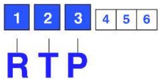
Digit 1, 2 and 3
CBM
Digit 4 – Dampers
L On left side
R On right side
2 Both sides
Digit 5 - Free
0
Digit 6 – Special Requirements
0 None
X Special requirement
Top plenum air conditioner

Digit 1, 2 and 3
CTP
Digit 4 - Free
0
Digit 5 - Free
0
Digit 6 – Special Requirements
0 None
X Special requirement
Notes
- The number and the position of the dampers (Air conditioner — digit 8, Air conditioner Base Module — digit 4) should be chosen as a function of the system lay-out. Having a rack column in the left side of the air conditioner column (AC column), a damper is needed in the left side ("S" or "L" at the same digits, see Fig. b — Chap.3). Having rack columns in both sides of air conditioner column, two dampers are required ("E" or "2" at the same digits, see AC2 column in the Fig. d — Chap.3).
- In a XDFN system with (n) Rack columns and (n + 1) AC columns, (n) air conditioners will be "Base cooling" (B at digit 10) and just one should be "Redundant cooling" (R at digit 10).
- Air conditioning column (AC column) is supplied, as standard, with bottom connections and with long aesthetic doors and it is complete of base module and top plenum. The entire column is factory-assembled and is 2400 mm height. In case of transport problems (for instance in case of column too high) or request of rear connections, unit will have to be selected with short doors (see also information on para. 11.1). Air conditioner digits 8 and 12 will be set accordingly.
- When the smoke detection and fire extinguishing option is chosen (see para. 6.3), then digit 14 of air conditioner depends on system configuration, and it has to be set as follows:
a. 1 AC column + 1 rack column (see Fig. b - Chap.3), digit 14 of air conditioner set as 2;
b. 2 AC columns + 1 rack column (see Fig. c - Chap.3), one air conditioner with digit 14 set as 2, the other one with digit 14 as 1;
c. 3 AC columns + 2 rack columns (see Fig. d - Chap.3), two air conditioners with digit 14 set as 2, the other one with digit 14 as 1.
Rack


Digit 1, 2 and 3
RAC
Digit 4 - Front door and configuration
3 All height transparent door, with top plenum
2 All height solid door, with top plenum
1 Base module with backup ventilation
0 Without base module
Digit 6 – Fire Detection and extinguishing
0 None
A Master fire detection and extinguishing system
B Slave fire detection and extinguishing system
C Smoke detector
Digit 7 - UPS Inside
0 None
A GXT2 - 1500 for back up ventilation
B GXT2 - 2000 for back up vent. and load protection
C GXT2 - 3000 for back up vent. and load protection
D GXT2 - 4500 for back up vent. and load protection
E GXT2 - 6000 for back up vent. and load protection
Digit 8 – Power distribution unit (PDU) & Power strip 0 None
A PDU with 8 sockets
B PDU with 8 sockets and 3 power strips (6 outlets each power strip)
C PDU with 8 sockets and 6 power strips (6 outlets each power strip)
Digit 9 – Monitoring
0 None
1 Via SNMP
Digit 10 - UPS Web Card
0 None
W Web card for UPS
C PLP and Wooden Crate
S Seaworthy
Digit 15 – Special Requirements
0 None
X Special requirement
Notes
- Rack column is supplied, as standard, with bottom connections and with long aesthetic doors and it is complete of base module and top plenum. The entire column is factory-assembled and is 2400 mm height. In case of transport problems (for instance in case of column too high) or request of rear connections, unit will have to be selected with short doors (see also information on para. 11.1). Rack digits 4, 5 and 12 will be set accordingly.
- When the smoke detection and fire extinguishing option is chosen (see para. 6.3), then digit 6 of rack depends on system configuration, and it has to be set as follows:
a. 1 AC column + 1 rack column (see Fig. b - Chap.3), digit 6 of rack set as A;
b. 2 AC columns + 1 rack column (see Fig. c - Chap.3), digit 6 of rack set as A;
c. 3 AC columns + 2 rack columns (see Fig. d - Chap.3), one rack with digit 6 set as A, the other one with digit 6 as B.
Base module rack

Digit 1, 2 and 3
RBM
Digit 4 – Backup Ventilation single phase / 230 V
1 Backup ventilation
Digit 5 - Free
0
Digit 6 – Special Requirements
0 None
X Special requirement
Top plenum rack
Digit 1, 2 and 3
RBM
Digit 4 – Backup Ventilation single phase / 230 V
1 Backup ventilation
Digit 5 - Free
0
Digit 6 – Special Requirements
0 None
X Special requirement
Index
1 - Preliminary operations .... 1
1.1 - Packing (see Fig. 1 - Enclosures H) 1
1.2 - Inspection 1
1.3 - Handling.... 1
2 - Operating range ...... 1
2.1 - Indoor and outdoor operative limits 1
2.2 - Storage limits 1
2.3 - Noise level limits 1
3 - Positioning 2
4 - Installation .... 3
4.1 - Base module 3
5 - Refrigeration connections .... 3
5.1 - Refrigeration pipeline connections (A version) 3
5.2 - Vacuum creation and refrigerant charge 6
5.3 - Refrigeration circuits 6
6 - Water connections ...... 6
6.1 - General warnings 6
6.2 - Water connections 7
6.3 - Cooling water connections (W only) 7
6.4 - Adding ethylene glycol (W only) 7
7 - Electrical connections 8
7.1 - Cooling module (see Fig. 1 - Enclosures F) 8
7.2 - Rack module (see Fig. 2, Fig. 3 and Fig. 4 - Enclosures F) 9
7.3 - Mutual connections between Cooling and Rack Module 9
7.4 - Safety warnings and Standards 9
8 - Cooling module start-up 9
8.1 - First start-up (or after long standstill) 9
8.2 - Starting and stopping 10
8.3 - Checking the refrigeration piping pressure drops 10
9 - XDFN complete system start-up 10
9.1 - Rack 42 U's space management 10
9.2 - First start-up 10
9.3 - Starting and stopping 11
9.4 - Suggested main checkup 11
10 - Cooling module operation....11
11 - Cooling module calibrations & regulation (at start-up) 12
11.1 - Setting the Electric Expansion Valve 12
11.2 - Environment protection 12
12 - Maintenance/Spare Parts 13
12.1 - Safety instructions 13
12.2 - Kit Hiromatic evolution L1 for Rack module (see Fig. 2 - Enclosures G) 13
12.3 - Spare parts 13
12.4 - Maintenance schedule 13
12.5 - Refrigeration circuit 15
12.6 - Dismantling the unit 15
12.7 - Regulation (EC) no. 842/2006 (F-gas) 15
Enclosures
HUMIDAIR humidifier ...... A - 1
Technical data tables B-1
Installation drawings C-1
Refrigerant and hydraulic connections D - 1
Refrigeration and hydraulic circuits E-1
Electrical connections ...... F - 1
Maintenance G-1
Packing H-1
1 – Preliminary operations
1.1 - Packing (see Fig. 1 - Enclosures H)
The units are usually packed on a wooden pallet (1), with shockproof angle pieces in pressed cardboard (2, 3, 4)/polystyrene (5), panels in cardboard (6)/polystyrene (7) and flexible polythene film (8).
Base module and plenum are packed in pressed carboard (see Fig. 2 – Enclosures H).
1.1.1 - Special packing (options)
Special packing for sea transport, consisting of a wooden box or crate, can be supplied on request.
1.2 - Inspection
On receiving the equipment immediately check its condition; report any damage to the transport company at once.
1.3 - Handling
•Always keep the unit vertically upright and do not leave it out in the open.
- Transport the unit using a fork lift truck with front—shoulders at least 1.5 m high, to avoid upsetting danger.
Fig. a - Unit handling

natural_image
Yellow forklift with black frame, standing beside a large door (no visible text or symbols)2 – Operating range
2.1 - Indoor and outdoor operative limits
XDFN system are provided for operating within the following working ranges (the limits concern new units on which correct installation has already been made):
All versions
| Indoor air conditions, surrounding the XDFN system | from: 18°C, 40% R.H. | |
| to: 28°C, 50% R.H | ||
| Power supply tolerances | 400V ± 10%, 3ph, 50Hz ± 2Hz | |
For XDFN system with air conditioner type A
| Outdoor temperature: lower limit | |
| Exceeding of winter lower limits will temporarily cause a compressor stop. | |
| down to -20°C below -21°C | |
| standard unit with standard condensing control | Consult HPAC Technical Sales Support |
| Outdoor temperature: higher limit | |
| This limit is determined by coupled condenser model. Exceeding of this limit (or a lack of maintenance), could cause a compressor stop by HP safety thermostat. Reset to normal operation can only be carried out manually. | |
| Relative position room unit vs. remote condenser | |
| From unit to condenser max distance up | to 30 m equivalent length |
| From unit to condenser max geodetic height (1) (2) | from 20 m to -3 m |
| Requirements | |
| Pipe diameter see Tab. b | |
| Oil traps on vertical line of gas refrigerant | every 6 m, max |
| Extra oil charge see Enclosures B, Tab. 8a | |
| Condenser design | |
| Additional non return valve on delivery line, at 1 m from compressor | mandatory |
| Additional non return valve on liquid line after condenser | mandatory |
(1) Positive difference in height: condenser above conditioner
(2) Negative difference in height: condenser below conditioner
For XDFN system with air conditioner type W
| Water or mixture temperature to condenser, lower limit (other information on para. 6.4) | min. 5°C |
For XDFN system with air conditioner type C
| Chilled water circuit | |
| inlet water temperature | min. 5°C |
| water pressure | max. 16 bar |
| Max. differential pressures on the modulating valve (2 or 3 ways)Max. differential pressure through the closed valve: ΔpcvMax. differential pressure across the valve for modulating service: Δpms | |
| models | p_cv (kPa) | p_ns (kPa) |
| X25UC | 200 | 300 |
2.2 - Storage limits
All versions
| Storage conditions | from: | -5°C (not condensing) |
| to: | 45°C (not condensing) |
2.3 - Noise level limits
The sound pressure level in free field at 1.5 m height and 2 m in front of the cooling module, with compressor and fan in operations, is less than 60 dBA for all models.
3 – Positioning
The units are available in the configurations shown below.
Fig. b - Basic configuration air path (one rack, one air conditioner)

Fig. c — Full redundancy configuration air path (one rack, two air conditioners)

Fig. d - Advanced redundancy configuration air path (n racks, n+1 air conditioners)

flowchart
graph TD
    A["AC UNIT 1"] --> B["RACK 1"]
    B --> C["AC UNIT 2"]
    C --> D["RACK 2"]
    D --> E["AC UNIT 3"]
    style A fill:#f9f,stroke:#333
    style B fill:#ccf,stroke:#333
    style C fill:#cfc,stroke:#333
    style D fill:#fcc,stroke:#333
    style E fill:#ffc,stroke:#333
See overall dimensions and service area drawings in Enclosures C.
4 – Installation
ATTENTION: The conditioner must never be installed out of doors.
See drawings in Enclosures C.
4.1 - Base module
If there is no raised floor below the unit it is recommended to choose rear connections. See also information on Enclosure D-1.
5 – Refrigeration connections
5.1 – Refrigeration pipeline connections (A version)
The air condensing units are delivered helium—pressurized at 1 bar.

The discharge operation of the room unit pressurized with helium (at 1 bar) and the de-welding of the bottoms from the connections must be carried out as last operations, immediately followed by the connection and emptying of the whole system.
5.1.1 - General layout (Tab. a)
1) In soft or hard copper.
The diameter required is stated in Tab. b.
If the installer intends to use pipes of a larger diameter (e.g. for long winding runs) then consult HPAC Technical Sales Support.
Use as short refrigeration pipelines as possible to minimize the total charge of refrigerant and the pressure drops. For long runs (over 30 equivalent m) contact HPAC Technical Sales Support.
Lay the horizontal gas pipes with 1% downward gradient towards the refrigerant flow.
2) Reduce the number of bends, which must be of large radius, to a minimum.
3) Insulate the piping as specified in Tab. a. If the pipes are put next to electrical cables it is advised to insulate them to avoid damage to cable insulation.
4) There must be a minimum separation of 20 mm between the gas and liquid pipelines.
If this is not possible insulate both lines.
5) Support both horizontal and vertical pipes with vibration—damping clamps (which include rubber gaskets). Place these every 1.5 – 2 m.
Fig. e - Recommended pipe layout

Tab. a - Condenser positioning
| CONDENSER POSITION | CONDENSER ABOVE CONDITIONER | CONDENSER AND CONDITIONER AT SAME LEVEL | CONDENSER BELOW CONDITIONER (not recommended) | ||
| INSULA-TION | gas | int. | necessary necessary | necessary | |
| ext. | only for aesthetic reasons only for aesthetic reasons only for aesthetic reasons | ||||
| liq. | int. | absolutely not | not necessary | no (expose to cold underfloor air) | |
| ext. | only for aesthetic reasons | only if exposed to sun | only if exposed to sun | ||
| LAYOUT | 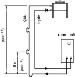 (*) Oil traps every 6 m of vertical piping (*) Oil traps every 6 m of vertical piping |  |  | ||
| (**) see Chap. 2. | |||||
5.1.2 - Pipe diameter
The diameters of the connecting pipes between the conditioner and the condensing unit listed in Tab. b must be respected, otherwise the guarantee becomes invalid.
Tab. b — Pipe diameters (room unit — remote condenser)
| STANDARD PIPE DIAMETERS(Valid for equivalent lengths up to 30 m) | ||||
| MOD. | copper tube external diameter x thickness [mm] R407C | copper tube external diameter x thickness [mm] R22 | ||
| Gas | Liquid | Gas | Liquid | |
| X13 | 14 X 1 | 14 X 1 | 16 X 1 | 16 X 1 |
| X17 | 16 X 1 | 16 X 1 | 16 X 1 | 16 X 1 |
| X20 | 18 X 1 | 16 X 1 | 22 X 1 | 18 X 1 |
| X23 | 22 X 1 | 18 X 1 | 22 X 1 | 18 X 1 |

When the pipes are more than 30 m long, contact Technical Support Department
5.1.3 – Installing pipelines
The discharge operation of the room unit pressurized with helium (at 1 bar) and the de-welding of the bottoms from the connections must be carried out as last operations, immediately followed by the connection and emptying of the whole system.
1) Lay the piping, taking note of the following:
- Welding:
• All joints must be braze—welded.
- Avoid butt welds by using sleeves or enlarging one of the pipes using a pipe opener.
- Use silver-based solders and the correct apparatus.
- Guarantee a correct weld as a refrigerant leak, or a faulty weld which leads to a leak later on, can seriously damage the air conditioner.
- Always use large—radius curves (bending radius at least equal to pipe diameter). Bend the pipes as follows:
- soft copper: by hand or bending device.
- hard copper: use preformed curves. Do not overheat the pipes when welding so as to minimize oxidation.
2) Connect the pipes to the condenser:
- Condensers with butt-welded pipe connections: cut the pipe, enlarge it and weld it to the pipeline.
- Condensers with threaded tap connections: flange the pipes and connect.
RESPECT THE DIRECTION OF REFRIGERANT FLOW (SEE LABELS ON REFRIGERANT CONNECTIONS).
3) Wash out the pipelines as follows:
a) Plug up the free ends of the pipes.
b) Connect a helium or nitrogen cylinder, fitted with a reducer (max. pressure 10 bar), to the 14'' SAE Schrader valve of the condenser.
c) Pressurize the pipes with helium or nitrogen.
d) Unplug the pipes instantaneously.
e) Repeat a) - d) several times.
THIS OPERATION IS ESPECIALLY IMPORTANT WHEN HARD COPPER PIPING IS USED.
4) Open all the room unit shut-off valve.
5) Discharge the room unit pressurized with helium (at 1 bar) opening the charge valves so that all the branches of the circuit are discharged (e.g. on the receiver, on the low pressure side and on the compressor delivery).
6) De-weld the bottoms from the connections of the room unit.
7) Fix (weld) the pipes to the connections on the air conditioner.
8) Connect the refrigerant safety valve to the outdoor with a 16 copper pipe.
Tab. c - Weight of refrigerant contained in piping during operation
| EXTERNAL PIPE DIAMETER (mm) | gas (*) | liquid (+), at different condensing temperatures R407C (kg/m) R22 (kg/m) | liquid (+), at different condensing temperatures | ||||
| 35.0 °C | 46.0 °C | 57.0 °C | 35.0 °C | 46.0 °C | 57.0 °C | ||
| 10 x 1 0.0031 0.06 | 0.06 0.05 | 0.06 0.06 0.05 | |||||
| 12 x 1 0.0049 0.09 | 0.09 0.08 | 0.09 0.09 0.08 | |||||
| 14 x 1 0.0068 0.11 | 0.11 0.10 | 0.12 0.12 0.11 | |||||
| 16 x 1 0.0085 0.17 | 0.16 0.15 | 0.18 0.17 0.16 | |||||
| 18 x 1 0.012 0.23 | 0.22 0.20 0.24 | 0.23 0.21 | |||||
| 22 x 1 0.019 0.34 | 0.32 0.31 0.36 | 0.34 0.33 | |||||
| 28 x 1 0.033 0.58 | 0.55 0.52 0.61 | 0.58 0.55 | |||||
(*) Due to the small weight influence (at 15.5 bar – discharge temp. 65°C), only 0.062 kg/l for R407C and R22 is considered.
(+) Liquid pressure and density varies according to condensing temperature (see refrigerant tables).
Tab. d - Equivalent lengths (m) of: curves, shut-off and non-return valves
| Nominal diameter (mm) |  |  |  | 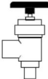 |  |
| 90° | 45° | 180° | 90° | ||
| 12 | 0.50 | 0.25 | 0.75 | 2.10 | 1.90 |
| 14 | 0.53 | 0.26 | 0.80 | 2.20 | 2.00 |
| 16 | 0.55 | 0.27 | 0.85 | 2.40 | 2.10 |
| 18 | 0.60 | 0.30 | 0.95 | 2.70 | 2.40 |
| 22 | 0.70 | 0.35 | 1.10 | 3.20 | 2.80 |
| 28 | 0.80 | 0.45 | 1.30 | 4.00 | 3.30 |
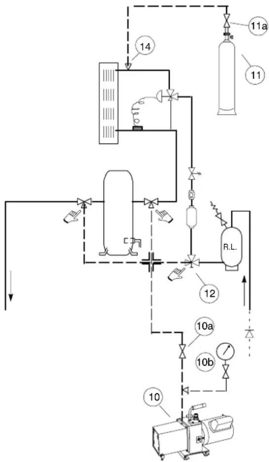
5.2 - Vacuum creation and refrigerant charge

Check the refrigerant type to be used on the data plate of the air conditioner and on the refrigerating compressor.
Fig. f — Pump and refrigerant charging cylinder connection for vacuum creation and refrigerant charge
flowchart
graph TD
    A["14"] --> B["Reactor Unit"]
    B --> C["11a"]
    B --> D["11"]
    B --> E["R.L."]
    E --> F["12"]
    F --> G["10a"]
    F --> H["10b"]
    G --> I["Control Unit"]
    H --> I
    I --> J["10"]
    J --> K["Reactor Unit"]
5.2.1 - R407C precharge (A version)
1) Open all cocks of the system including those used for pressurizing (ambient unit and condensing unit). By this operation all the components of the refrigerating circuit must be subject to vacuum.
2) Connect a proper, high efficiency vacuum pump (10) suitable for polyester oils to the couplings:
- Compressor intake and delivery using, if available, the three-way Rotalock cocks, coupling 1/4" SAE (make sure that all three ways are open), otherwise the Schrader valves welded on the pipings.
- Three-way Rotalock cock, coupling 1/4" SAE of the liquid receiver (12) (make sure that all three ways are open).
3) Provide for a connection with refrigerant cylinder before making vacuum.
4) Make the system vacuum up to 0.3 absolute mbar and after 3 hours check if 1.3 absolute mbar have not been exceeded. This condition warrants a humidity lower than 50 ppm inside the system. If the complete vacuum is not possible, this means that there are some leaks (to be removed according to the instructions in 8 below).
NEVER USE THE COMPRESSOR TO CREATE A VACUUM (THIS INVALIDATES ITS GUARANTEE).
5) Power the microprocessor control (QF8 on).
6) Go to the Electric Expansion Valve control display. Enter in manual simulation mode and open the valve with 5 V signal, see also user manual of electric expansion valve to change from automatic to manual mode and vice versa.
7) Break the vacuum as follows:
a) Close the pump cock (10) for the vacuum (10).
b) Open the cock of the refrigerant cylinder (11a) until the system reaches a pressure value of about 4 bar.

The refrigerant must be introduced and charged by taking only liquid fluid from the cylinder.
c) At this point both the vacuum pump and the refrigerant cylinder can be disconnected as follows:
c1) close the cylinder cock (11a)
c2) close the way 1/4" SAE of the Rotalock cocks and/or the connected Schrader valves.
8) Inspect all connections/joints using a leak detector. If a leak is found, empty the pipes and the condenser, seal the leak and repeat the instructions in 3) - 7).
9) Go to Electric Expansion Valve control in simulation mode, close the valve at 0 V signal, and exit from the menu. Switch off the air conditioner, so, at the next switching on, the expansion valve will be driven by its superheating control, automatically.
10) Now the machine is ready for completing the charge and the start—up.
11) Charge the refrigerant (ONLY LIQUID) by means of the charge valve placed at the evaporator inlet.
5.2.2 - Refrigerant charge (A version)
1) Open the front and rear doors of the racks if already connected to the cooling module (if any).
2) Start the air conditioner in manual mode [QS and QF8 on], as described in para. 8.1.
3) Switch on the EC fan, manually, giving the fan speed analog output 1 equal to 80%. One AC damper must be open.
4) Manually start the compressor. It runs automatically at 100%, full load.
5) Guarantee a constant condensing temperature (preferably 42 - 45 °C).
6) Charge the unit until the bubbles in the sight glass have disappeared and the working conditions of the entire refrigeration circuit have become normal and assuring a subcooling of about 4 K.
7) Verify that the superheat is about 7K.
5.3 - Refrigeration circuits
See drawings in Enclosure E.
6 – Water connections
6.1 – General warnings
ENSURE THAT THE TUBING DOES NOT OBSTRUCT THE AIR FLOW(Under only).
IF THE TUBING IS TO RUN OUTDOORS, ADD ETHYLENE GLYCOL TO THE CIRCUIT AS DESCRIBED IN PARA. 6.4.
6.2 - Water connections
- Condensate drain (Fig. g):
- Use galvanized steel, PVC or flexible polythene tubing.
- Allow a 2% gradient towards the drain.
- There must be a drain trap (1) placed on the rear side of the air condizioner base module.
- Fill the drain trap with water (2).
Fig. g - Condensate drain

- Humidifier (optional): See Enclosure A.
6.3 - Cooling water connections (W only)
The unit must receive cooling water as follows:
a) from an external cooling water source, in open circuit (para. 6.3.1 and Figures in Enclosures).
b) using a Dry cooler, in closed circuit (para. 6.3.2).
- Connect the piping as shown in Enclosures D.
- It is advisable to use hoses to be connected, with 3-piece joints, to the condenser water inlet and outlet couplings.
- IMPORTANT: fit a standard strainer on the inlet water piping.
- Place shut-off ball valves at the conditioner inlet and outlet to allow easy maintenance.
- It is advisable to install a water drain system at the lowest point in the circuit.
- Fully drain the piping before connecting it to the air conditioner.
6.3.1 - Notes for open circuit applications
- Use the unit with mains or well water. DO NOT USE WATER FROM AN EVAPORATIVE COOLING TOWER UNLESS THE FILLING WATER HARDNESS IS CONTROLLED.
- The water pressure must be 2 – 10 bar (if this is not so, contact the Technical Support Department).
•The required water flow at different temperatures is given in our catalogues or on request. - If necessary (very low water temperature) insulate both pipes using Armaflex insulation.
6.3.2 - Notes for closed circuit applications
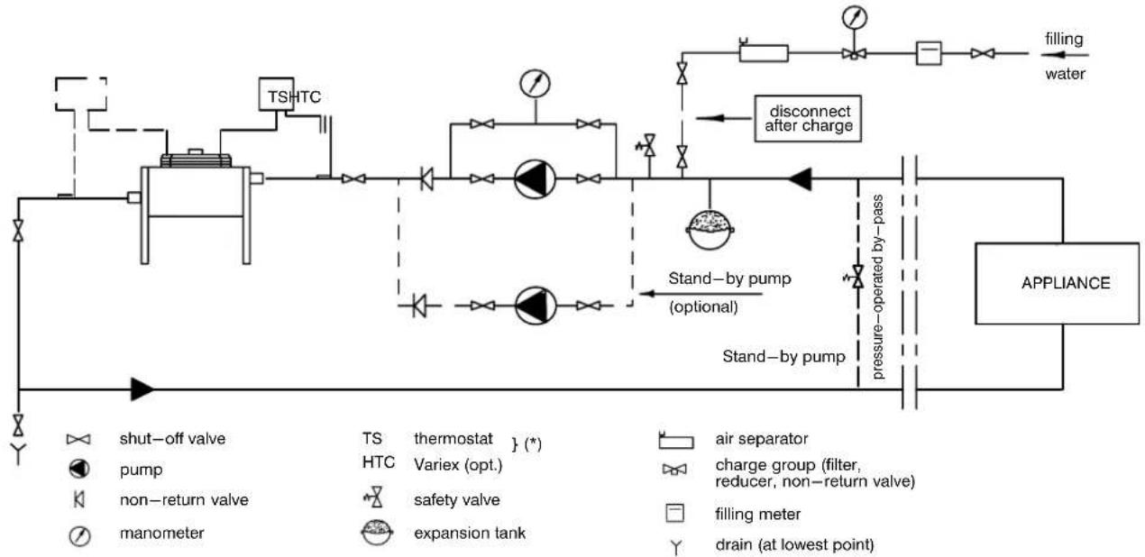
- The installation in Fig. h is indicative only; for individual installations follow the project diagram.
- Install a pump system calculated on the basis of the flow and total head of the system (see project data), and controlled by the compressor running (see label on the unit).
•Insulate both pipes using Armaflex insulation. - VERY IMPORTANT: Add water and ethylene glycol to the circuit, when the ambient temperature is below zero (referring also to para. 6.4). Do not exceed the nominal operating pressure of the circuit components.
- Bleed air out of the circuit.
6.4 - Adding ethylene glycol (W only)
Tab. e — Ethylene glycol to be added to water
| freezing temperature (°C) | 0 -5 -11 -18 -27 -39 | |||||
| ethylene glycol to add to water (% in weight of total mixture) | 0 | 10 | 20 | 30 | 40 | 50 |
N.B. Values are for Shell antifreeze 402. For different brands check manufacturer's data.
NOTES:
• To avoid stratification run the circulation pump for at least 30 min. after adding any glycol.
- After adding water to the water circuit, disconnect the unit from the sanitary water piping system; in this way the water mixed with glycol won't return into the same piping system.
•After any topping—up of water check the glycol concentration and add any glycol if necessary.
•The hydraulic features of the system vary by adding glycol. Therefore check the head and the flow rate of the pump to be used.
Fig. h – Advised Dry cooler Installation
flowchart
graph TD
    A["shut-off valve"] --> B["pump"]
    B --> C["non-return valve"]
    C --> D["manometer"]
    D --> E["TSHTC"]
    E --> F["disconnect after charge"]
    F --> G["stand-by pump (optional)"]
    G --> H["charge group (filter, reducer, non-return valve)"]
    H --> I["air separator"]
    I --> J["filling meter"]
    J --> K["drain (at lowest point)"]
    K --> L["APPLIANCE"]
    L --> M["filling water"]
    M --> N["windship"]
    style A fill:#f9f,stroke:#333
    style L fill:#ccf,stroke:#333
See hydraulic drawings in the Enclosures D.
7 – Electrical connections
7.1 - Cooling module (see Fig. 1 - Enclosures F)
7.1.1 - Power input
Power Supply 400 V 3N 50 Hz+EARTH
Cable power size 4x6 mm²+EARTH
7.1.2 - Electrical connections
1) Before proceeding with the electrical connections, ensure that:
• all electrical components are undamaged;
• all terminal screws are tight;
• the supply voltage and frequency are as indicated on the unit.
2) Power supply cable connections:
- Connect the cable to the Line inlet terminal board.
- Use the cable size defined according to the flow, the supply voltage and the installation type.
- Protect the supply using a back-up fuse.
- Do not fit the supply cable in the raceways inside the machine electric board.
- Use multipolar cables with sheath (CEI20–22) only.
3) Wiring connections (Fig. i):
- Connections for remote on-off consent must be done by the installer.
• The General Alarm terminals allow remote alarm signalling.
4) In case of short circuit, check the sticking of the involved switch and possibly replace it.
Fig. i - Cooling module electrical connections

flowchart
graph TD
    A["remote on-off (CLOSED = ON)"] --> B["2\n020"]
    C["clogged filter (CF) (OPEN = OK)"] --> D["90\n91"]
    E["water leakage (LWD)"] --> F["1\n102"]
    G["GENERAL ALARM (400.401 NC = alarm or unit off)"] --> H["400 (NC)\n401 (C)\n402 (NO)"]
    I["operating fan (CLOSED = ON)"] --> J["70\n71"]
    K["WARNING ALARM"] --> L["300\n301\n302"]
    M["Warning ALARM"] --> N["3000\n3010\n3020"]
7.1.3 - Protection degree IP2x check
After whole of the connections and installation works, check and verify the protection degree IP2x (protection against finger access, std. IEC 60364-1) at the boundary of the air conditioner.
7.1.4 - Protective features of EC fan
The EC fan has been provided with the following protective features:
• Over temperature of electronics
•Over temperature of motor
- Locked rotor protection
- Short circuit at the motor output
With any of these failures, the motor stops (electronically – no potential separation), the status relay is released. NO automatic restart. To reset the alarm, power supply has to be switched off for min. 20s once motor is at standstill.
- Mains under—voltage detection: if mains voltage falls below 3ph/290Vac (typical value) for 5s minimum, motor will be swithed off (only by electronics, no potential separation), status relay is released. If mains voltage returns to correct values, the motor will restart automatically.
- Phase failure recognition: if one phase failes for 5s minimum, motor will be switched off (only by electronics, no potential separation), status relay is released. If all 3 phases return to correct values, the motor will restart automatically within 10–40s.
The power supply for an external speed setting potentiometer is short—circuit protected.
Motor is overload—protected via motor current limitation.
Warning! Leakage current of the motor is 7 mA roughly.
7.2 - Rack module (see Fig. 2, Fig. 3 and Fig. 4 - Enclosures F)
7.2.1 - Power input
Power supply: 230 V 1 Phase 50 Hz+EARTH
Input power cable size 2x2,5 mm ^4 +EARTH
7.2.2 - Rack electrical panel
On the front left side of the rack the relevant electrical board is located, closed by 6 screws. It has been designed in order to fulfill the following functions:
1) to manage the power input, from std network (single phase + earth) or from UPS, according to the local rules;
2) to contain the microprocessor, able to check the temperatures, manage the backup ventilation, support the monitoring via SNMP (opt.)
3) to power supply and control the damper and backup ventilation fan
4) to contain the specific slot RJ45 (8 poles) where to connect the Hiromatic kit accessory for rack.
5) to manage the optional devices, i.e. fire extinguishing system, open door sensors, smokestat.
7.2.3 - PDU power limitations (see Fig. 4 - Enclosures F)
To reduce the risk of overload, do not load any single socket with more than 16A. Each PDU is protected with specific residual current MCB in order to reduce the risk of electric shock.
7.2.4 - Power strip limitations (see Fig. 4 - Enclosures F)
To reduce the risk of overload, do not load any single strip with more than its rated maximum: 3400W, 16A.
7.2.5 - Smokestat (see Fig. 5 - Enclosures F)
This device is installed, as option, on the top rear side of the rack module. To reset the smokestat sensor, it is necessary to switch off and after to switch on the QF1 main switch located in the front electrical panel of rack module.
7.3 - Mutual connections between Cooling and Rack Module
Between the rack and the air conditioning modules, following connections are required to be set on the field:
•Auxiliary connections between rack and air conditioning
- Electrical connections between dampers of contiguous air conditioners.
- Fire detection and extinguishing system (opt.)
- Hirobus data cable between air conditioners of the same system.
Further details on the specific wiring diagram included inside the unit.
7.4 – Safety warnings and Standards
IMPORTANT SAFETY NOTES FOR INSTALLATION Check the grounding when installing the rack and the air conditioning units. Check the max power absorbed from each strip. Check the voltage before connecting any equipment to the PDU and before to switch on the XDFN. Open the main switch installed inside the rack and the air-conditioning before any maintenance operation. Maintenance operation to be done only by authorized staff. The product conforms to EU directives EN 60204-1.
8 – Cooling module start—up
8.1 - First start-up (or after long standstill)
TO PREVENT COMPRESSOR DAMAGE THE CRANKCASE(S) MUST BE PREHEATED FOR AT LEAST 4 HOURS BEFORE CONDITIONER START—UP (FAILURE TO DO SO INVALIDATES THE GUARANTEE).
Start the air conditioner as follows:
1) Open all valves in the refrigeration circuit according to the instruction label attached to the valve.
2) W only: Open all valves in the water circuit according to the instruction label attached to the valve.
3) Ensure that the refrigerant charge is correct (see Chap. 5).
4) Using a leak detector, verify that there are no refrigerant leaks. If there are any, then repair the leak and recharge as described in Chap. 5.
5) At least 4 hours before start—up, close QS and QF8 on the electrical panel.
6) Verify the operation of the crankcase heater.
7) Check that there are no water leakages.
8) Close all MCBs on the electrical panel.
9) Check the supply voltage on all phases.
10) ENSURE THAT THE COMPRESSOR HAS BEEN PREHEATED FOR AT LEAST 4 HOURS BEFORE STARTING THE UNIT.
11) Start the air conditioner by pressing the specific button on the Hiromatic control (local ON-OFF).
12) Check the electrical absorption of all components (see Tab. 4 Enclosures B).
13) Check the electrical absorption of the external condenser/Dry cooler.
14) If the phase sequence relay detects an uncorrect compressor electrical connection, an alarm is activated and the compressor can not start. In this case it is necessary to invert the electrical connections of the phases supplying the corresponding digital scroll compressor.
15) Ensure that the fans rotate in the correct direction (see arrow on fan).
CAUTION: risk of contact with rotating devices.
16) Ensure that all control system settings are correct and that there are no alarms (see Control manual).
17) W only: Verify the water flow.
18) W only: For closed circuit units ensure that the water pump starts when the compressor starts.
8.2 - Starting and stopping
• ALWAYS ENSURE THAT EACH CRANKCASE HAS BEEN PREHEATED.
FOR BRIEF STOPPAGES KEEP THE SUPPLY TO THE CRANKCASE HEATER.
Turn on the air conditioner by the relevant Hiromatic control. The fan starts immediately (the fan always works when the unit is ON); after approx. 30 seconds the regulation is activated, so the cooling (compressor), heating (electric heaters), humidifying and dehumidifying devices can start.
Adjust the set-point as indicated in air conditioner Control manual.
Stop the air conditioner by the relative local OFF of Hiromatic.
8.3 — Checking the refrigeration piping pressure drops
The air conditioner is equipped with connections to check the refrigeration piping pressure drops:
room unit → condenser → room unit
To carry out this operation it is necessary to use 2 calibrated manometers and connect them as follows:
M1, connected to the compressor delivery valve; M2, connected to the Schrader valve (2) of Fig. j.
When the compressoris ruuning, check M1 and M2.
N.B.: Repeat this test, inverting the manometers: to calculate the correct p consider the average value of the two readings.
Refrigeration pipeline Pressure drops ( p bar), at 45°C (approx. R407C = R22):
• At the same geodetic level: p (bar) = M1-M2
- When condenser is above the room unit: p (bar) = M1-M2+geodetic difference (m x 1,1:10,2)
- When condenser is below the room unit: p (bar) = M1-M2-geodetic difference (m x 1,1:10,2)
Fig. j - Refrigerant line components

| 1 Liquid receiver valve |
| 2 Filter dryer inlet Schrader valve |
| 3 Filter dryer |
| 4 Sight glass |
| 5 Solenoid valve |
9 – XDFN complete system start-up
9.1 - Rack 42 U's space management
Always use blanking panels to fill all remaining not used front U-spaces in the rack.
Empty units (U) of space inside the rack could drive to a hot air "short circuit" back to the inlet of the equipment, increasing unnecessarily the air inlet temperature to the servers.
To avoid this bypass, the enclosed blanking panels (supplied loose inside the rack module, no.12 x size 1—U and no.5 x size 6—U) must be installed in the front of the rack where there are unused vertical spaces. So, either a customer device or a blanking panel must fill every space of the rack.
And in general, cabling arrangements in the rack should be tidy and well organized in such a way to avoid restriction of the airflow section.
9.2 - First start-up
Part one
Following operations must be done switching off the electrical power.
1) Connect all the air conditioners (if more than one) together with the Hirobus cable, cables for emergency ventilation and for dampers between contiguous air conditioners.
2) Follow the instructions in the air conditioner control manual
3) Verify the correct electrical connections between the air conditioners and between air conditioners and racks; see electrical connections inside the manual and specific wiring diagram included inside the unit.
4) Remember that the auxiliary circuits of the air conditioner and the auxiliary circuits of the rack should be connected to an internal (optional) or external UPS. For air conditioning unit XDFN it is necessary to re-
move the bridges N1–N8 and R1–R8, and connect the terminals R8–N8–PE (230Vac 50Hz) to the UPS.
Part two
Power supply the auxiliary circuits of air conditioners switching on the relative magnetic circuit breaker (MCB)
5) In the air conditioners Hirobus network, make sure to have set via Hiromatic:
a) number of cooling modules member of the Hirobus network;
b) if there is a redundant conditioner, define one of them in stand—by status. The system microprocessor control automatically gives an I.D. number to each air conditioner, the number one as master;
c) define the rotation time for the stand—by conditioner.
6) Switch on all the MCB's on the electrical panel of air conditioners
7) Switch on all the necessary MCB's on the electrical panel of rack modules and make sure that:
a) front and rear doors of racks are closed.
b) there is no air by—pass from back to front of devices installed inside racks. In order to avoid bypass in case of empty space, the supplied blank panels must be used.
8) Air conditioners will work properly and efficiently only inside the operative conditions indicated on product documentation.
9.3 - Starting and stopping
1) Use the local on/off button on the relative Hiromatic to switch on/off the relative air conditioner.
2) In case of air conditioners system (two or more air conditioners connected via Hirobus), during normal operation the Hiromatic display shows the status of each conditioner. Pushing local on/off in this case we can switch off each air conditioners, selecting its specific identify number inside.
3) Backup ventilation will start under at least one of the following conditions:
a) all the air conditioner/s adjacent to the rack is/are in local off, alarm status or no power status.
b) too high inlet/outlet air temperature detected by the sensors mounted inside the rack connected to Microface.
c) black out, or lack of electrical power supply, if present UPS: in this case all the auxiliary circuits (racks and air conditioners) should be connected to an UPS (uninterruptible power supply). Internal UPS is supplied as a rack option.
9.4 — Suggested main checkup
Use the following check list to have a first general check up of the system.
Adhere to all safety information and instruction given in the service manual and all local regulations.
Once the system is operating under load, check the various components, as follows:
1) Verify that one air conditioner (if more than one) is in stand—by and all others are working properly without any warnings or alarms activated.
2) Verify that fans are running properly (Microface controller automatically drives fan speed).
3) Ensure that the temperature and relative humidity are being controlled and the humidifier (optional) operates when required. The Microface controller for this application is designed to control the conditioner air delivery temperature (i.e. the inlet air temperature to the rack) and to control the air relative humidity measuring this value at the inlet side of air conditioners.
4) Ensure that digital scroll compressors are operating properly: Microface controller automatically drives compressor and cooling capacity modulation.
5)
a) A version only: ensure that the condensing controller, equipped inside air conditioner and driven by Microface, is calibrated and properly controls the external condenser fan operations.
b) C version only: ensure that chilled water 3-way valve is working properly. Microface automatically drives CW valve and capacity modulation.
c) W version only: ensure that the modulating control valve, equipped inside air conditioner and driven by Microface to control the condensing pressure, is calibrated and properly controls the condensing water flow through the brazed and plate condenser.
6) Check the correct position of air dampers equipped into the base module of air conditioners.
7) Ensure that backup ventilation and backup air damper work properly.
8) With all system working properly in local hirobus network, ensure that:
a) switching off one air conditioner (once a time) then the redundant one (in stand—by if present) will start to work properly and all the components (air dampers, fans, compressors, etc..) will continue to run well.
b) Coming back and switching on the air conditioner (before stopped as described in point 8a) the system will restart to work properly and with one air conditioners in stand—by.
c) Switching off the air conditioner(s) adjacent to one rack then automatically the relative backup ventilation will start to work. Coming back and switching on the adjacent(s) air conditioners then backup ventilation will be stopped and air conditioners will return to work properly.
d) With an internal UPS installed (optional for rack module) or with an external dedicated UPS, switching off the main electrical power supply, then automatically the backup ventilation starts up. And, on the contrary, switching on the main power supply automatically the backup fan turn off and the air conditioners will start to work properly.
10 - Cooling module operation
Unit operation is completely automatic. The below sequence explains how the unit operates :
- The air, sucked in by the fan(s), enters into the AC module.
•The air is immediately filtered into the AC module.
- The HUMITEMP (temperature + rel. humidity) sensor, verifies the state of the inlet air, and relays this information to the control system.
- Another temperature sensor verifies the state of the outlet air (air conditioner delivery) and relays this information to the control system.
•The treated air passes through the fans, which operate continuously, and is then dispersed out of the unit.
- The control system compares the relayed information to the set point and proportional band values programmed into its memory: it then commands the air conditioner to treat the air as follows (see also air conditioner Control manual):
•COOLING
Direct expansion mode (DX)
The compressor is started and the cold refrigerant flows
through the evaporator, thus cooling the air passing over it. For fan and compressor operation see Control manual.
Chilled water mode (CW)
The chilled water flows through the chilled valve coil, thus cooling the air passing over it. The chilled water flow is controlled by a 0–10 Vdc proportional valve, which regulates the flow rate in order to obtain the exact amount of cooling required.
•HEATING
Electrical heating: if necessary the heating elements heat the air passing over them (see also Control manual).
- DEHUMIDIFICATION - optional
DX mode
The compressor moves 100% cooling capacity, thereby causing dehumidification (refer also to Control manual).
CW mode
The chilled water valve moves on full open position, thereby causing dehumidification when temperature drops below the dew point of the air.
N.B.: If, during dehumidification, the AC outlet air temperature drops below a specified level, dehumidification will be stopped if necessary (see LOW LIMIT intervention in Control manual).
If necessary, heating is used during dehumidification mode.
•HUMIDIFICATION – optional
The humidifier creates steam, which is distributed into the air stream via the steam distribution pipe (see also Enclosure A).
N.B.: Manual control can be performed using the control system (see air conditioner Control manual).
11 – Cooling module calibrations & regulation (at start—up)
•The air conditioner has already been factory tested.
- For calibrations of instruments installed on the external condensers/Dry coolers refer to the relevant manual.
- For control system calibrations refer to air conditioner Control manual (to prevent erratic operations do not use temperature and rel. humidity set points/proportional bands which differ excessively from the Standard Settings).
11.1 - Setting the Electric Expansion Valve
THIS OPERATION MUST BE PERFORMED BY AN EXPERIENCED REFRIGERATION TECHNICIAN.
The Electric Expansion Valve [Siemens MVL 661.15–0.4] is driven by its own linear magnetic actuator, 24Vac power supplied, trough a 0–10 Vdc signal coming from the controller [Siemens RWR62.732] located in the front panel (see Enclosure G, Fig. 1)
The valve is PN40, closed when not energized, high resolution with precise positioning control and position feedback signal, suitable for use with organic safety refrigerants
(R407C, R22, R134a, R410A, etc.). See the relative handbook, enclosed in the unit, for any required deeper information.
11.1.1 - Valve setting
Always disconnect the unit from the power supply.
In the electronic housing of the valve, four dipswitches has been preset at the factory:
dip switch 1 Off (it means input for positioning control as a voltage 0/2...10 Vdc signal)
dip switch 2 Off (it means no offset, modulation starting from zero)
dip switch 3 Off (it means position feedback as a voltage signal)
dip switch 4 On (it means max capacity setted at 63% of max admissible capacity of valve)
11.1.2 - Controller setting
The Electric Expansion Valve control has been factory preset with following relevant parameters:
refrigerant R407C
unit measurements bar/°C
superheating setpoint 7 K
MOP set point 15°C
superheating proportional band 9 K
other parameters at default value
See the relative controller handbook, enclosed in the unit, for any required deeper information
11.1.3 - Running modes
The dedicated controller automatically manages the valve openings in order to get a suitable superheating. The temperature and pressure values are continuously read by the relevant sensors.
It is also possible to drive the valve in manual mode for refrigerant charge operation (see para. 5.2)
11.1.4 - New settings
In order to manage unbalanced and cycling situations, the valve can be differently regulated as follows.
1) Strictly adhere to the suggestions available at the relevant handbooks of valve and controller.
2) Be sure about fulfilled guidelines, chapter no. 5.
3) Allow the compressor operate for 10 minutes in manual mode (100% cooling capacity) and the condensing control in manual mode having a suitable stable condensing temperature
4) Check on the display of EEV controller the actual value of superheating against the setted superheating and evaporating temperature value. If these parameters are not stable, it is possible to adjust at least two main values: the superheating proportional band and the superheating set point.
5) Restart the unit and its condensing control, in automatic mode, by Hiromatic
11.2 – Environment protection
A misuse or an incorrect calibration of the unit leads to increased energy consumption, resulting in an economic and environmental damage. Use the freecooling function, if available.
12 – Maintenance/Spare Parts
12.1 - Safety instructions
All maintenance operations must be carried out strictly observing the European and National accident prevention regulations. We refer especially to the accident prevention regulations concerning electrical systems, refrigerators, and manufacturing resources.
Maintenance may be done to air conditioning equipment only by authorized and qualified technicians.
To keep all warranties valid the maintenance must adhere to the manufacturer's regulations.

The work should be done in the system only when it is at standstill. Do this by switching off the air conditioner at the controller and the main switch. Post a warning sign saying: "DO NOT SWITCH ON."
Electrical components of device have to be switched off and be checked that they are not under voltage.
Ignoring the safety instructions can be dangerous to persons as well as to the environment.
Soiled parts always cause a loss of performance and for switch or control devices can lead to the break—down of a plant.
12.2 - Kit Hiromatic evolution L1 for Rack module (see Fig. 2 - Enclosures G)
This accessory allows to check up main parameters managed by electronic control of Rack module.
It is a loose supplied device, available on request, useful above all for service applications and to check up the rack status during start up operations.
12.3 - Spare parts
Only original spare parts made by Emerson Network Power may be used. Using third-party material can invalidate the warrantee. When making inquiries always refer to the "Component List" supplied with the equipment and specify the model number, serial number and, if available, the part number as well.
NOTES:
1) When a faulty component is replaced, follow the relevant manufacturer instructions.
2) When the spare parts must be welded, be carefully do not damage the internal parts (gaskets, seals, o-rings, etc.).
12.4 - Maintenance schedule
Monthly, quarterly, biannual and annual checks to be conducted according to the following guidelines.
All tasks and periods listed here are regulations from the manufacturer and need to be documented in an inspection report.

All these tasks should be carried out only by an authorized and trained technician. We recommend the Emerson Network Power Customer Service
Maintenance schedule
| COMPONENT | MAINTENANCE PERIOD EVERY | ||||
| 1 Month | 3 Months | 6 Months | 1 Year | ||
| FANSAttention,do not reach into the fan while the fan wheel is running. | Check for soiling, damage, corrosion, and proper fixing. X | ||||
| Check bearings noise. X | |||||
| Check blower balancing. Vibrations (mm/s). X | |||||
| Measure the current and power consumption. X | |||||
| Cleaning to preserve the function. X | |||||
| AIR FILTERS | Check for soiling, damage, corrosion. X | ||||
| Check state of filter. X | |||||
| Clean or replace if necessary. X | |||||
| Carry out controls more frequently in dusty environments. X | |||||
| CONTROL SYSTEM | Check for proper and functionally correct installation and surrounding conditions. X | ||||
| Check the function of the LEDs of the display's control system and the alarms. X | |||||
| Check the connections for electrical and mechanical function. X | |||||
| Check the functional elements (e.g. operational controls and display devices). | X | ||||
| Check the electrical/electronic and pneumatic input signals (e.g. sensors, remote controllers, command variable) for compliance with nominal values. | X | ||||
| Check control function, control signals, and safety chains. | X | ||||
| Adjust control function and control signals. | X | ||||
| HUMIDIFIER(if installed) | See appendix A. | ||||
| SWITCH CABINET POWER CIRCUITSAttention,electrical cables and electrical components of the air conditioner are under voltage. | Check the power supply on all phases. X | ||||
| Check the connections for electrical and mechanical function. X | |||||
| Check the power supply at all terminals. | X | ||||
| Measure power consumption at all connected consumers. | X | ||||
| Set, adjust, and tighten the functional elements (e.g. operational controls and display devices). | X | ||||
| Check safety equipment, e.g. thermal switch. | X | ||||
| Replace fuses (every 2 - 3 years) | X | ||||
| Check protective covers for completeness. | X | ||||
| COOLING WATER(W only) | Check cooling water circuit. | X | |||
| Check for damage, leaks, and proper fixing. | X | ||||
| Make sure there is no loss of water. | |||||
| COOLING WATER(W only)Only for closed circuits: | Make sure that the water pump works properly. | X | |||
| Deaerate circuits. | X | ||||
| Check whether the heat transfer medium of circuit-connected system is frost-proof. | X | ||||
| Check safety equipment for function. | |||||
| Check glycol% comparing minimum yearly ambient temperature. | X | ||||
| REFRIGERATION CIRCUITFluoride refrigerants increase the green-house effect and are subject to restrictions and norms, according to the national and European regulations. | Measure the working pressures and temperatures (to be done by a refrigeration technician). | X | |||
| Check the power consumption, measure head temperature, and check for possible abnormal operating sounds. | X | ||||
| Make sure that there is no frost building up on the evaporator and compressor. | X | ||||
| Check function of all regulating devices (power regulators, valves, etc.). | X | ||||
| Check safety devices for function. | X | ||||
| If the quantity of refrigerant is not enough, it needs to be reclaimed and refilled with completely new refrigerant. | |||||
| Check oil level at the sight glass. | X | ||||
| Carry out an oil test. | X | ||||
| Change the oil after every 8000 hours of operation. X | |||||
| Check crankcase heater for function. | X | ||||
| ELECTRIC EXPANSION VALVE and SUPERHEATING CONTROLLER | See appropriate manual. | ||||
| EXTERNAL CONDENSER/Dry cooler(if installed) | See appropriate manual. | ||||
| AIR DAMPER and SERVOMOTORS | Check correct opening/closing of damper | X | |||
12.5---Refrigerationcircuit
WHENREPAIRINGTHEREFRIGERATIONCIRCUIT COLLECTALLREFRIGERANTINACONTAINER:DO NOTALLOWITTOESCAPE.
- Wheneitherremoving(forrepairs)orchargingrefrigerantthismustalwaysbedoneonboththehighandlow pressuresidesofthecompressorsimultaneously.
• The compressor copper plated steel connection should be welded with basilos material containing a minimum of 5% silver.

1) Starttheunitasdescribedinpara.8.1.
2) Manually start the compressor (ensure the unit is not in dehumidification).
3) Waitafewminutestoallowconditionstostabilize.
4) Checkwhetherthereareanybubblesvisibleinthesight glass.Ifthereareany,thismeansthereisaleak,which mustbetraced(usingaleakdetector) andrepaired;then rechargetheunituntilnofurtherbubblesarevisible.
5) Usingamanometer, check that the evaporating temperature is above 0^ C.
6) Verify the water pressostatic valve (WV) setting (CHAP. 10).
7) Verify that the superheat is 5–8 K (to do this refer to Chap.10).
12.5.2---OilchargeR407C
Theoiltobeusedwhentoppingup(onlyifthereareany leaks) is EMKARATE RL 32–3MA or Mobil EAL Arctic 22CC(seeTab.fandTab.g).
Tab. f – EMKARATE RL 32–3MA oil (for R407C only)
| Viscosity at 40 °C | : | 31.2 cSt |
| Viscosity at 100 °C | : | 5.6 cSt |
| Viscosity index (ISO Grade) | : | 32 |
Tab.g---MobilArcticEAL22CCoil(forR407Conly)
| Density (at 15 °C) | : | 0.967 kg/l |
| Flash point (C.O.C.) | : | 245 °C |
| Pour point | : | <-54 °C |
| Viscosity at 40 °C | : | 23.6 cSt |
| Viscosity at 100 °C | : | 4.7 cSt |
| Viscosity index (ASTM D2270) | : | 130 |
These oils rapidly absorb the humidity present in the air when they are exposed to the atmosphere.
If the oil absorbs humidity, the ester molecules can break down, forming acidity.
Wethereforerecommendexposingtheoilforasshortatime as possible (no more than a few minutes) and, in case of toppingup,using exclusivelytheoilindicatedontherefrigerating compressor.
Normally 1 or 2–litre cans are available for this purpose; once they are opened, they must be completely used up. They must not be used after a long period, asthey absorb humidity.
Itisthereforeobviousthatthetapsofthecompressormust onlybeturned afterthewholeplanhasbeensubjectedtoa vacuumandpartialfilling.
12.5.3---OilchargeR22
Theoiltobeusedwhentoppingup(onlyifthereareany leaks)isSUNISO3GS.
Tah -SukorR22only)
| Density (at 15 °C) | : | 0.91 kg/l |
| Flash point (C.O.C.) | : | 178 °C |
| Pour point | : | <-40 °C |
| Viscosity at 40 °C | : | 29,5 cSt |
| Viscosity at 100 °C | : | 4,35 cSt |
| Coppoer corrosion (100 °C, 3 hr) ASTM D130 | : | 1 |
| Neutralization value | : | 0,03 máx. |
| Dielectric strenght | : | >30kV |

If oil leakages occur, the topping-up operation is necessary. (Contact the local Service before intervention).
12.6 ---Dismantlingtheunit
Themachinehasbeen designedandbuilttoensure continuousoperation.
The working life of some of them in components, such as the fan and the compressor, depends on them in maintenance that they receive.

The unit contains substances and components hazardousfortheenvironment(electroniccomponents,refrigeratinggasesandoils).Attheend oftheusefullife,whentheunitisdismantled,the operationmustbecarriedoutbyspecializedre-
frigerating technicians. The unit must be delivered to suitable centers specialized for the collection and disposal of equipment containing hazardous substances.
12.7 - Regulation (EC) no. 842/2006 (F-gas)
Stationaryairconditioning, refrigeration, heatpump equipments and stationaryfireprotection systems, placed into the European Community market and operating with fluorinated greenhouse gases (f -- gas), such as R407C, R134a, R410A, they havetocomply with the F - gas Regulation (applied since 04 July 2007).
(Be aware that refrigerants as R22 are not f-gas and theirrelevantregulationisReg.(EC)no.2037/2000).
Following notes havetobe considered when operating with the abovementioned equipments.
- Fluorinated greenhouse gases are covered by the KyotoProtocol.
- Thefluorinatedgreenhousegasesinthisequipment shouldnotbeventedtotheatmosphere.
- Referring to the value noted in Annex I of Regulation (EC) No842/2006 here below the global warming potential (GWP) of somemaiorf--gases
R-134a GWP 1300
R-407C GWP 1610
R-410A GWP 1890
- Operatorsoftheabovementionedapplications(stationaryrefrigeration,airconditioningandheatpump equipment,includingtheircircuits,aswellasfireprotectionsystems),whichcontainfluorinatedgreenhouse gases, shall, using all measures which are technically feasibleanddonotentaildisproportionatecost:
a. preventleakage of thesegases and as soon as possiblerepairany detected leakage.
b. ensure that they are checked for leakage by certified personnel.
c. ensure for putting in place arrangements for the proper recovery by certified personnel.
d. Incaseofapplicationscontaining3kg(6kgincase of hermetically sealed system) or more of f-gases: certifiedpersonnelprovidesregularleaktesting(accordingtoReg.1516/2007andReg.1497/2007) and maintainrecordsofmaintenanceactivitiesinadedicatedlogbook.
e. Recovery for the purpose of recycling, reclamation or destruction of the fluorinated greenhouse gases, pursuant to Art.4 (Recovery) of Reg.842/2006, shall take place before the final disposal of that equipment and when appropriate, during its servicing and maintenance.
-Operator,accordingtoReg.842/2006,Article2,point6,meansthenaturalorlegalpersonexercisingactualpoweroverthetechnicalfunctioningoftheequipmentandsystemcoveredbytheRegulation.AMemberStatemay,indefined,specificsituations,designatetheownerasbeingresponsiblefortheoperator'sobligations.
- Directmethodsofleakagecheckingapprovedbythe manufacturer(Reg.1516/2007andReg.1497/2007)
a.gasdetectiondeviceadaptedtotherefrigerantinthe system; thesensitiveofportablegasdetectiondevices(asadirecttestmethod)shallbeatleastfive gramsparyear.
b. proprietary bubble solutions / soapsuds.
•Additionalinformationlocatedintoadedicatedlabel ofunit(Reg.1494/2007)
a. Where fluorinated greenhouse gas is foreseen to be added to the equipment outside of the manufacturing site at the point of installation, a dedicated label accommodates notation of both the quantity (kg) pre-charged in the manufacturing plant and of the quantity charged at the installations as well as the resulting total quantity of f-gas as a combination of the abovementioned quantities, in an manner which conform to the eligibility and indelibility.
Our split units are usually not pre-charged on factory, in this case the total quantity of refrigerant chargedintheunithastobewrittenintherelevant label, during the commissioning operation at the installationsite.
b. Our packaged units (not split) operating with f-gas are usually full charged on factory and the total amount of refrigerant charge is already reported on the label. In this case, the label has noneed off further written information.
c. Ingenerally, the abovementioned information has been located in the main name plate of relevant unit.
d. For equipment with multiple separate (disconnected)refrigerationcircuits, inregardstodifferentiatesrequirementsonthebasisofthequantityoff-gascontained, therequiredinformationaboutrefrigerantchargequantitieshastobelistedseparatelyfor eachindividualcircuit.
e. Forequipments with separate indoor and outdoor sections connected by refrigerant piping, the label information will be on that part of the equipment which is initially charged with therefrigerant. Incase of asplitsystem (separate indoor and outdoor sections) without a factory pre-charge of refrigerant, themandatory label information will be on that part of the product requirement which contains themost suitable service points for charging or recovering the fluorinated greenhouse gas (es).
- Safety data sheets of f-gases used into the products are available as separated documents.
App. A – HUMIDAIR humidifier
A.1 - Preface
The HUMIDAIR represents the best humidifier technology available, guaranteeing the steam as clean as possible to-
gether with simple maintenance.
In order to obtain optimum performance from the HUMID-AIR it is advisable to read this manual carefully.
Tab. a - Humidair specifications
| XDFN MODEL | HUMIDAIR MODEL | MAIN POWER SUPPLIES (V ± 10%) | SETTING [kg/h] * [A] | ABSORBED CURRENT [kW] [l] [l/min.] [l/min.] | POWER | MAX. CYL-INDER WATER VOLUME | MAX. SUPPLY WATER QUANTITY | MAX. DRAIN WATER QUANTITY |
| X13...25 | KUECLA | 230V / 1ph / 50Hz | 0.6...2.0 | 6.5 | 1.5 | 1.70 | 0.6 | 4.0 |
For humidifier current (FLA) and rated power, refer to electrical features in the air conditioner manual.
(*) Unit is factory—set to produce about the minimum value (see Microface manual).
A.2 - Installation
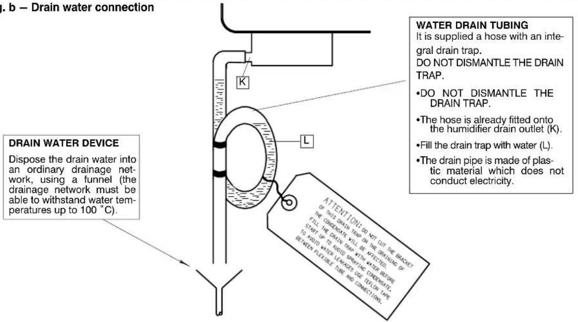
The humidifier is supplied already mounted within the air conditioner. The only necessary operations are the connections for the supply water (Fig. a) and drain water (Fig. b).
Fig. a - Supply water connection

Fig. b - Drain water connection
NOTES:
1) Allow a 2% gradient towards the drain outlet.
2) Avoid back pressures in the drain piping.
A.3 - Humidair components
The components of the HUMIDAIR humidifiers are shown below.
Fig. c - The humidifier and its connections

flowchart
graph TD
    A["DRAIN VALVE ASSEMBLY (D)"] --> B["FILLING CUP"]
    B --> C["overflow tube"]
    C --> D["steaming cylinder"]
    D --> E["drain valve"]
    E --> F["water drain outlet"]
    G["SUPPLY VALVE (F)"] --> H["Fresh pump"]
    H --> I["drain tank"]
    I --> J["drain valve"]
    K["steam outlet"] --> L["level electrode"]
    M["flow from humidityifier"] --> N["to electrical supply"]
    O["flow from level sensor"] --> P["to interface"]
    Q["flow from supply valve to interface"] --> R["flow from supply valve to interface"]
    S["flow from water supply"] --> T["flow from supply valve to interface"]
A.4 - Start-up and operation
A.4.1 - Start-up
Before using the humidifier, check the following:
•Supply and drain connections.
- That the cut-off tap is open.
- All wiring.
•Earthing.
- Steam hose connection between steam cylinder and distributor.
To start the humidifier simply switch on the air conditioner, which will in turn automatically start and stop the humidifier as required. The (adjustable) parameters which determine humidifier operation have already been factory—preset (see HIROMATIC manual).
A.4.2 - Operation
Water, provided it contains even a small quantity of salts in solution, is a conductor of electricity. Therefore, if the steam cylinder is filled with water and a potential difference is applied between the electrodes, the water behaves like an ordinary electrical resistance and becomes hot, thus creating steam.
The steam production rate can be controlled by varying the water level in the cylinder; the higher the water level, the deeper the electrodes are immersed into it and the greater the steam production.
Note
When starting with an empty cylinder, the water conductivity is normally insufficient for the HUMIDIFIER STEAM OUTPUT to be reached immediately.
Therefore the humidifier produces as much steam as possible to fill the cylinder completely. Any evaporation water is immediately refilled.
The drain valve is kept shut and therefore, as the steam does not contain any salts, the conductivity of the water within the cylinder slowly increases until the HUMIDIFIER STEAM OUTPUT is obtained.
The length of the start-up period depends upon the water conductivity. For very conductive water it may occur that the HUMIDIFIER STEAM OUTPUT is obtained immediately.
A.5 - Maintenance
A.5.1 - Removing the steam cylinder
To remove the steam cylinder, proceed as follows (see Fig. c):
1) Open the General Switch relative to the humidifier.
2) Drain all the water from the cylinder by activating "HUM. DRAIN" in the CONTROL Service menu several times (see Control manual).
3) Disconnect the steam hose (S) (made of non-conductive rubber).
4) Disconnect the power electrode wires (P) and level sensor wire (L).
5) Undo the clip (R).
6) Pull the cylinder (C) out of its gland at the bottom (G).
A.5.2 - Replacing the steam cylinder
When the steam cylinder is approaching the stage where it needs to be replaced, warning A25 is generated (see Control manual) to advise the user that the cylinder must be replaced. To replace the cylinder, proceed as follows (see Fig. c):
1) Carry out the instructions in para. A.5.1.
2) Using the new cylinder, carry out 4)—6) of para. 5.1 in reverse order.
3) Connect the steam hose (S); the clip on the hose needs to be tightened only slightly.
4) Manually switch the humidifier on for 2–3 minutes (in the HIROMATIC Service menu). Then switch it off.
5) Drain the water as for 2) in para. A.5.1.
6) If the air conditioner features a HIROMATIC with Graphic display, reset the humidifier working hours (window no. 1 of PARAMETER MENU) to zero.
7) Close the General Switch relative to the humidifier.
A.5.3 – Annual maintenance
Annually (e.g. before any close—down period) carry out the following service on the humidifier (see Fig. c):
1) Carry out the instructions in para. A.5.1.
2) Disconnect the supply (F) and drain (D) valve wires.
3) Unscrew and remove the drain tank (T).
4) Unscrew the drain valve assembly screws (V).
5) Remove the drain valve assembly.
6) Unscrew and remove the drain valve solenoid (O).
7) Unscrew and remove the drain valve armature (D).
8) Clean all parts of the drain valve using a commercially available descaling agent (to remove any incrustations).
9) Detach the hose from the supply valve.
10) Remove the supply valve connection (N).
11) Unscrew the supply valve (F) and remove it.
12) Clean the supply valve using a jet of water.
13) Replace any hose which has become hard and brittle.
14) Thoroughly flush the drain line (E).
15) Reassemble the humidifier by carrying out the above instructions in reverse order.
ATTENTION
Always empty the cylinder completely before any close-down period.
A.6 - Humidifier spare part list
It is recommended the use of original spare parts. When placing an order quote the part code, as well as the air conditioner model no. and serial no.
| POSITION(see Fig. c) | CODE DESCRIPTION | Humidair ModelKUECLA | Notes |
| C 141090 Steam cylinder CLA 1 (*) | |||
| T Drain tank 1 | |||
| U Filling cup 1 | |||
| K Rubber gasket for drain tank 1 | |||
| A 183241 Drain valve armature 1 | |||
| H 183242 Drain valve housing 1 | |||
| O 254007 Drain valve solenoid 1 (*) | |||
| 254905 Isolator for level sensor | 1 | ||
(+) = Spare part recommended
(*) = Consumable material
Tab. 2 – Electrical data
| Configuration Model | Power supply | FLA [A] | LRA [A] | RESIDUAL-CURRENT CIRCUIT BREAKERS IΔn = 0.3A (400V) | |
| Cooling + Electrical heatingFan + compressor + electrical heaters | X13UA/W | 50 Hz3Ph / 400V + N+ PE | 18.0 58.0 25A | ||
| X17UA/W | 18.2 71.0 25A | ||||
| X20UA/W | 18.8 79.0 25A | ||||
| X23UA/W | 24.0 109.0 32A | ||||
| X25UC | 8.0 8.0 10A | ||||
| Cooling + Electrical heating + HumidificationFan + compressor + electrical heaters + humidifier | X13UA/W | 50 Hz3Ph / 400V + N+ PE | 24.5 65.0 32A | ||
| X17UA/W | 24.7 78.0 32A | ||||
| X20UA/W | 25.3 86.0 32A | ||||
| X23UA/W | 30.5 116.0 40A | ||||
| X25UC | 15.0 15.0 20A | ||||
NOTES:
• The cables have to be sized in compliance with local standards and according to the type and characteristics (e.g. Amperes) of installation.
- The specific power of the user-installed switch, must be lower than 300,000 A ^2 x s.
•Prescriptions on the differential relay required to the user:
• for special places (healthcare facilities, etc...) comply with the local regulations;
- For ordinary places, a low sensitivity is suggested (300 mA) coordinated with the value of the ground heater (IEC 364): Ra v 50/la (Art. 413.1.4.1, CEI 64–8);
- In case of frequent over—voltages with mains impulse, it is advisable to install a selective differential and to evaluate the need for adopting other devices.
Tab. 3 – EC fan connections
| Model | Standard (VDC) Min-/ Max-Wert (VDC) | |
| X13UA/W | 7.5 6.0 / 10.0 | |
| X17UA/W | 8.5 6.0 / 10.0 | |
| X20UA/W | 9.0 6.0 / 10.0 | |
| X23UA/W | 10.0 6.0 / 10.0 | |
| X25UC | 10.0 6.0 / 10.0 | |
NOTE:
The EC fan settings can be modified acting on the control display (see control manual for air conditioner module)
Tab. 4 – Electrical data (standard component)
| Component | EC FAN(3 Ph - 400 V ±10% - 50 Hz) | COMPRESSOR(3 Ph - 400 V ±10% - 50 Hz)REFRIGERANT R407C | MOTORWinding resistance (Ohm) | ELECTRICAL HEATING(3Ph - 400V - 50Hz) | |||||||
| Model | OA^1 | FLA | LRA^2 | Nominal power (kW) ^1 | OA^3 | FLA | LRA | Nominal power (kW) ^3 | FLA | Nominal power (kW) ^2 | |
| X13UA/W | 1.4 | 3.6 | 0.1 | 0.84 | 6.1 | 10.0 | 50.0 | 3.34 | 3.88 | 4.4 | 3.0 |
| X17UA/W | 2.0 | 3.6 | 0.1 | 1.22 | 8.0 | 10.2 | 63.0 | 4.25 | 2.75 | 4.4 | 3.0 |
| X20UA/W | 2.2 | 3.6 | 0.1 | 1.35 | 8.7 | 10.8 | 71.0 | 4.91 | 2.27 | 4.4 | 3.0 |
| X23UA/W | 3.0 | 3.6 | 0.1 | 1.85 | 10.8 | 16.0 | 101.0 | 5.68 | 1.79 | 4.4 | 3.0 |
| X25UC | 3.1 | 3.6 | 0.1 | 1.87 | - | - | - | - | - | 4.4 | 3.0 |
(1) At standard operating conditions (see Product Documentation)
(2) Fan is equipped with an internal soft starter wich needs LRA approx to Zero Ampere
(3) At nominal operating conditions: Condensing temperature 50°C (see also Product Documentation)
Tab. 5 – Electrical data (optional component)
| Component | HUMIDIFIER(230 V ± 10% / 1 Ph / 50 Hz) | |
| Model | FLA [A] | Nominal power [kW] |
| X13-17-20-23-25 | 6.5 | 1.5 |
Tab. 6 – Electrical data Rack Module
| Back up fan | ||
| Fan type | centrifugal | |
| quantity | 2 | |
| OA, each | A | 1.4 |
| FLA, each | A | 1.4 |
| LRA, each | A | 3.0 |
| Power input | W | 300 |
| Damper actuator | ||
| Power supply | Vac | 24 |
| Power consumption | VA | 24 peak |
Tab. 7 – Calibrations of electrical components
| COMPONENT SETTING | NOTES Contact | |||
| Low Pressure Switch (LP) | STOP 2 bargSTART 2.8 bargDIFFER. (fixed) 0.8 bar(fixed setting - automatic reset) | Delayed automatic reset(see MICROFACE/HIROMATIC manual) |  | Normally closed |
| High Pressure Switch (HP) | STOP 26 bargSTART 20 bargDIFFER. (fixed) 6.0 bar(fixed setting - manual reset) |  Reset Reset | Normally closed | |
| Clogged filter differential pressure switch (CF) | Filter G4 = 200 Pa |  Setting ring Setting ring | Normally open | |
| Min. air flow differential pressure switch | STOP 100 Pa |  | Normally open | |
| Electric expansion valve and superheating controller | See para. 11.1 |  | ||
| Condensing control valve - 3 way type (W version only) | SET 17 bargConfiguration switches:1 characteristic OFF2 control signal OFF3 Volts or mA OFF0-10 Vdc proportional modulating action | 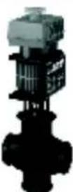 | Normally closed through the condenser side when de-energized | |
| Servomotor for 3-way chilled water valve | 0-10 Vdc proportional modulating action. |  | ||
| 3-way chilled water valve | Modulating action. |  | ||
Tab. 8 - R407C/R22 refrigerant and oil charge for air cooled models (A type)
| MODEL | BASE REFRIGERANT CHARGE ^(2) [kg – each circuit] | BASE OIL CHARGE (1) (liters)oil within compressorinitial oil charge Max topping up | |
| X13UA | 4.8 1.36 1.24 | ||
| X17UA | 5.2 1.95 1.83 | ||
| X20UA | 5.6 1.77 1.66 | ||
| X23UA | 6.6 2.51 2.40 | ||
Tab. 8a – Refrigerant and oil pipe charge
| Pipe diameter [mm]Liquid | Refrigerant pipe charge[kg/m] for distances D (3) | Oil pipe charge [l] | |
| charge to be added for every 10 m over 30 m between AC and COND without hot gas reheating | charge to be added for every 10 m over 30 m between AC and COND with hot gas reheating (4) | ||
| 10 0.070 0.05 0.10 | |||
| 12 0.101 0.08 0.16 | |||
| 14 0.137 0.12 0.24 | |||
| 16 0.178 0.15 0.30 | |||
| 18 0.227 0.19 0.38 | |||
| 22 0.339 0.25 0.50 | |||
(1) The recommended oil for units with R407C refrigerant is EMKARATE RL 32-3MA. For units with R22 refrigerant pay attention to compressor label: if requested mineral oil this will be SUNISO 3 GS, if requested ester oil this will be EMKARATE RL 32-3MA.
(2) Unit coupled with remote condenser suggested for ambient temperature up to 35^ C. The final charge must be precisely defined in field.
(3) For distance D see Fig. 1.
(4) Topping up is requested for short pipeline too, due to the extra-charge of refrigerant.
N.B.: The air conditioner is supplied pressurized with helium at 1 bar.
Fig. 1 – Pipeline air conditioner – condenser

Tab. 9 - Refrigerant and oil charge for water cooled models (W type)
| MODEL | R407C/R22 REFRIGERANT CHARGE [kg – each circuit] | OIL CHARGE (1) (liters) |
| X13UW | 4.2 | 1.36 |
| X17UW | 4.2 | 1.95 |
| X20UW | 4.5 | 1.77 |
| X23UW | 4.8 | 2.51 |
N.B.: The air conditioner is supplied complete with refrigerant and oil.
(1) The recommended oil for units with R407C refrigerant is EMKARATE RL 32–3MA. For units with R22 refrigerant pay attention to compressor label: if requested mineral oil this will be SUNISO 3 GS, if requested ester oil this will be EMKARATE RL 32–3MA.
Space requirement (one)
First be sure to have the space in your area available, and the holes on the raised floor for electrical, refrigerant connections and data cables.
Fig. 1 Hole on the raised floor for piping and electrical connections COOLING MODULE

Fig. 2 Holes on the raised floor for electrical connections RACK MODULE
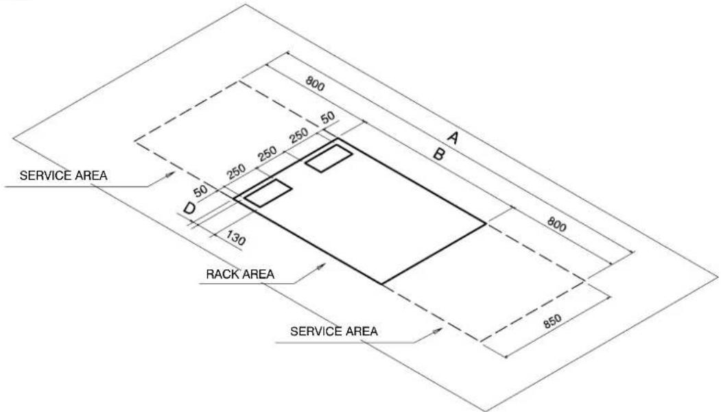
| Dimensions (mm) | ||||
| A B C D | ||||
| With short doors 2800 1200 30 50 | ||||
| With all height doors 2840 1240 50 70 | ||||
Space requirement (two)
Room required for the basic cooling column. Please multiply by all the planned modules.
Fig. 3 Overall dimensions
Cooling module components
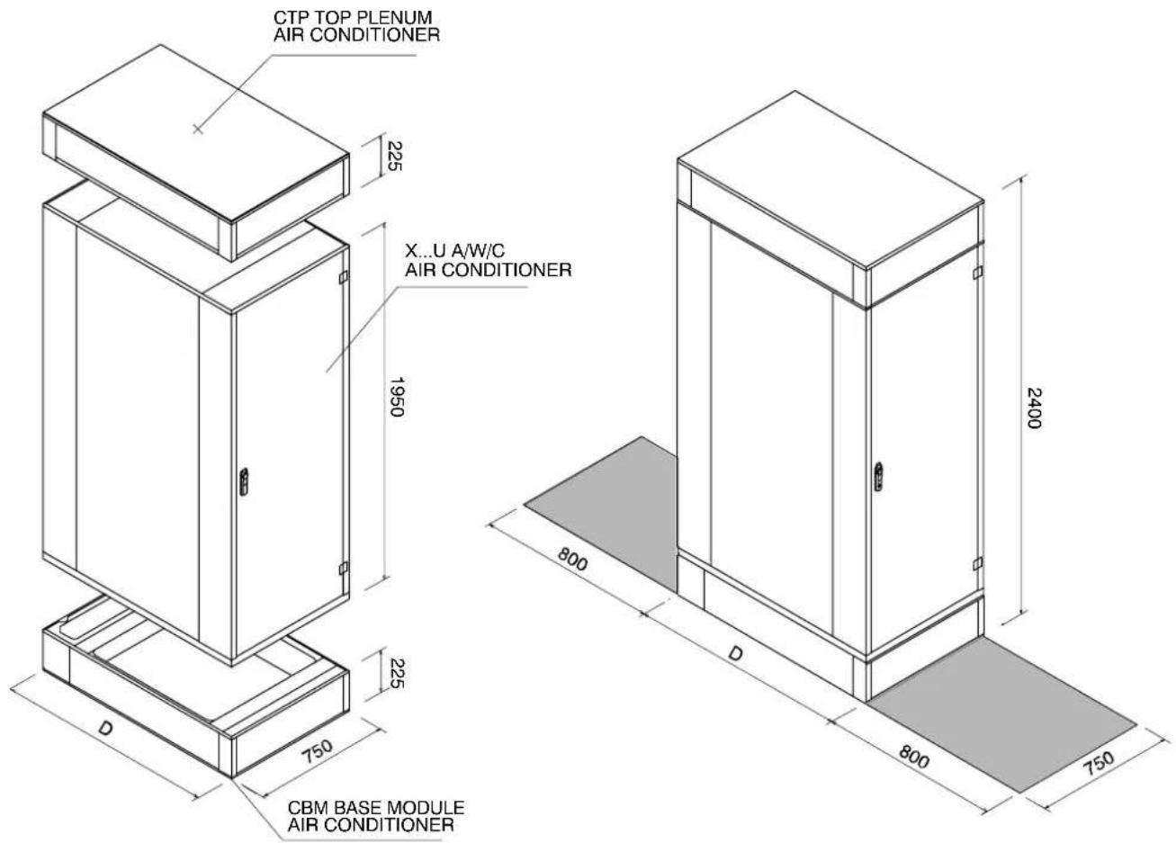
Fig. 4 Service Area
Cooling module
| COOLING MODULE (1) | DIMENSIONS | APPROX. NET WEIGHTS (kg) version | ||||||
| Width (mm) | Depth D (mm) | Height (mm) | Footprint ( m^2 ) | A W C | ||||
| With all height doors | With short doors | |||||||
| X13U A/W 750 1240 | 1200 2400 0.9 413 | 423 | ||||||
| X17U A/W 750 1240 | 1200 2400 0.9 425 | 435 | ||||||
| X20U A/W 750 1240 | 1200 2400 0.9 435 | 445 | ||||||
| X23U A/W 750 1240 | 1200 2400 0.9 445 | 455 | ||||||
| X25UC 750 1240 1200 2400 0.9 | 410 | |||||||
(1) Air conditioner column: base module + air conditioning unit + top plenum
Space requirement (three)
Room required for the basic rack module. Please multiply by all the planned columns.
Fig. 5 Overall dimensions
Rack module components
Fig. 6 Service Area
Rack module
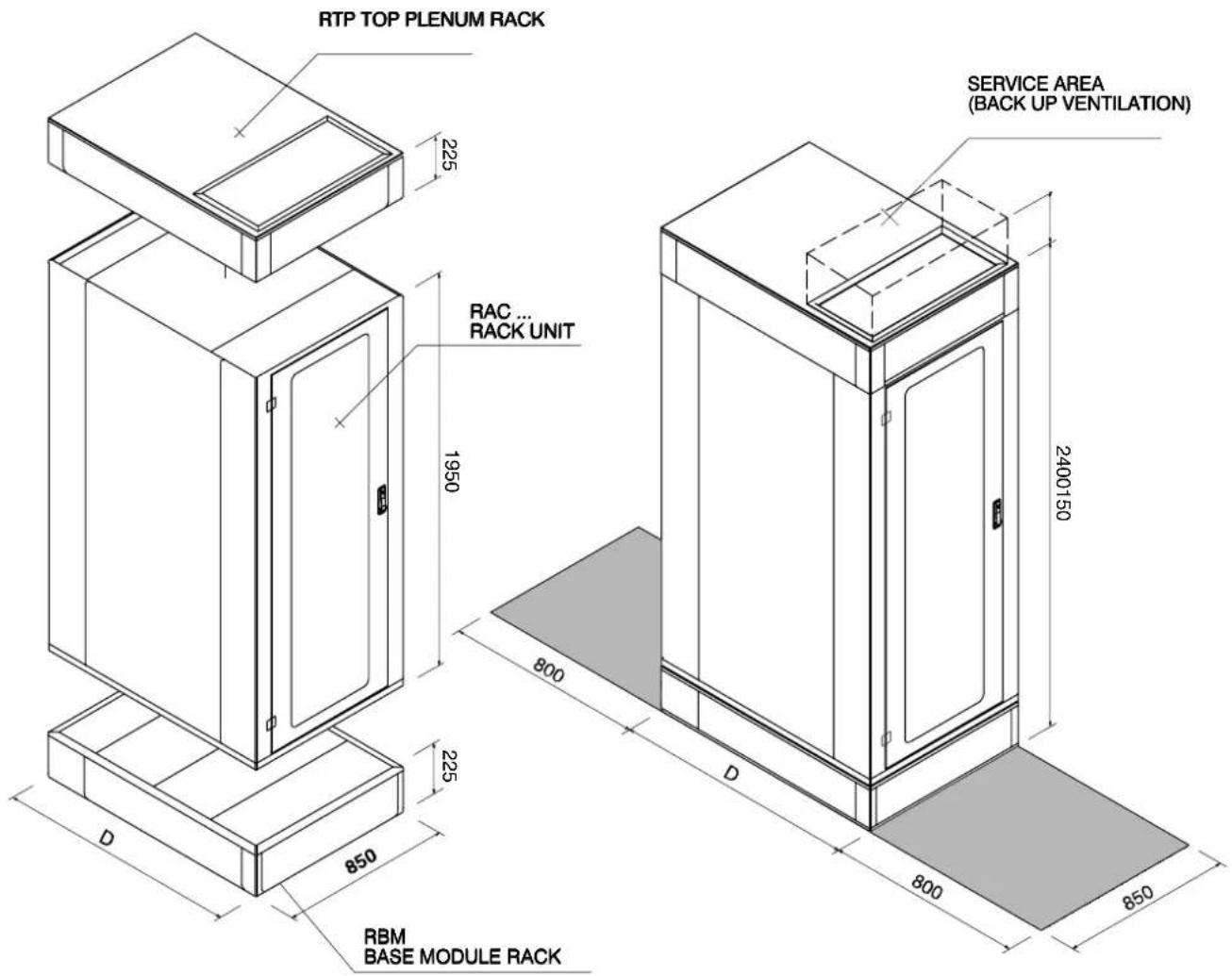
| RACK MODULE (1) | DIMENSIONS | NET WEIGHTS(kg)version | ||||
| Width (mm) | Depth D (mm) | Height (mm) | Footprint ( m^2 ) A | |||
| With all heightdoors | With shortdoors | |||||
| Rack | 850 1240 1200 | 2400 1.02 319 | ||||
(1) Rack column: base module + rack unit + top plenum
Building the system (one)
First locate the two base modules, as shown in the drawing.
A gasket must be applied on the connecting surface.
Fig. 7 Step 1

DETAIL A - LATERAL VIEW
•gasket location:
see the sectioned lines
•gasket thickness:
3 mm

Building the system (two)
The rack will be located over the corresponding base module. And then the cooling module. Between the pieces the gasket.
Fig. 8 Step 2


Building the system (three)
The rack top plenum will be placed on the top. In between the gasket.
Fig. 9 Step 3

Building the system (four)
The air conditioner top plenum will be placed on the top. In between the gasket.
Fig. 10 Step 4
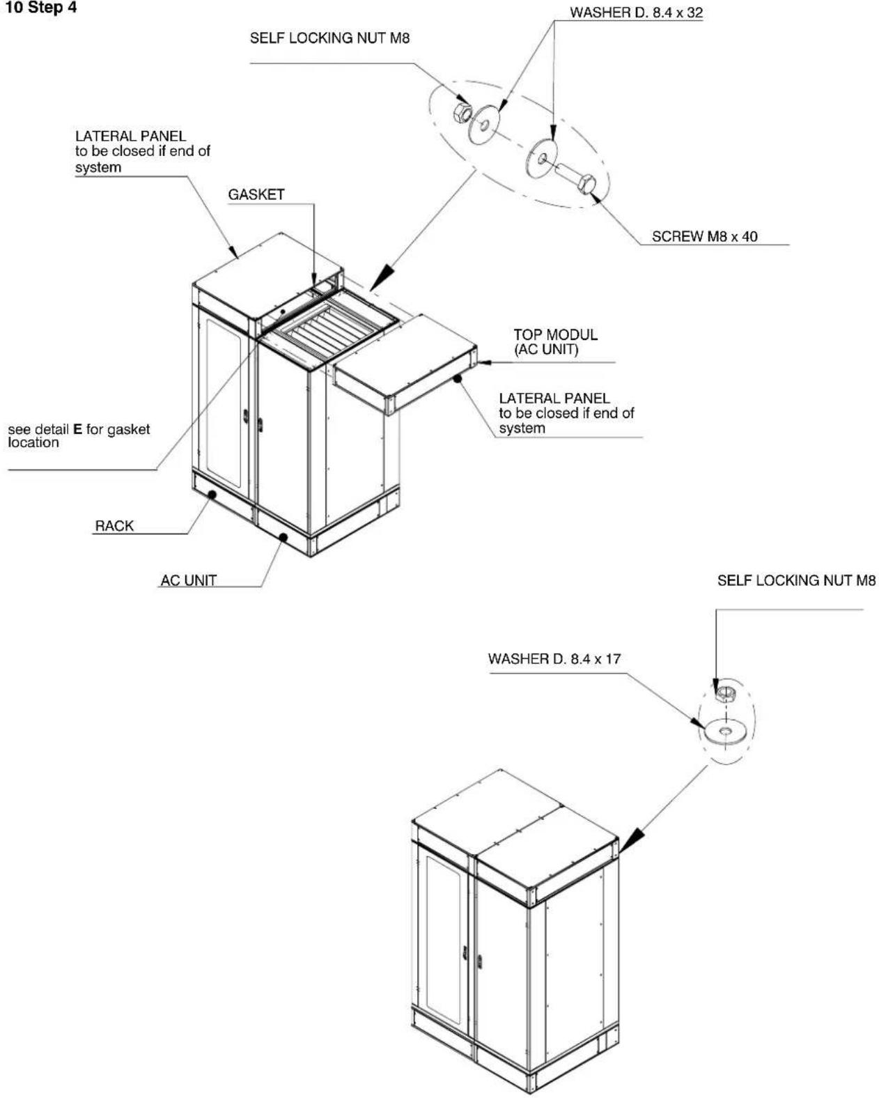
DETAIL D - TOP VIEW
•gasket location: see the sectioned lines
•gasket thickness: 3 mm

DEATILE – LATERAL VIEW
•gasket location: see the sectioned lines
•gasket thickness: 3 mm

Fig. 1 Connections
COOLING MODULE

(*) Rear connections possible with short doors only
| Unit Connection | Version | |||
| A | W | C | ||
| IL | Liquid line inlet ** | OD 16 mm | ||
| OG | Gas line outlet ** | OD 18 mm | ||
| ICW | Chilled water inlet | 1" GAS-F | ||
| OCW | Chilled water outlet | 1" GAS-F | ||
| IWC | Water to condenser inlet | 3/4" GAS-F | ||
| OWC | Water from condenser outlet | 3/4" GAS-F | ||
| CD | Condensate drain | ID 20 mm | ||
| HF | Humidifier feed (opt.) | 1/2" GAS-M | ||
| HD | Humidifier drain (opt.) | ID 22 mm | ||
| EC | Electrical power supply | Hole 0 48 mm | ||
** Connection size only. The dimension of the connecting pipe depends on unit model and refrigerant (see Tab. b, Chap. 5).
Fig. 2 Connections RACK MODULE

BOTTOM CONNECTIONS
Sealed holes (dia. 63 mm) for power and data cables. Two supplied seals: one for 9 cables max dia. 10,5 mm; one for 4 cables max dia. 16,5 mm. The remaining four holes are supplied with simple gland cable.
(*) Rear connections possible with short doors only
Fig. 1 XDFN XxxUA
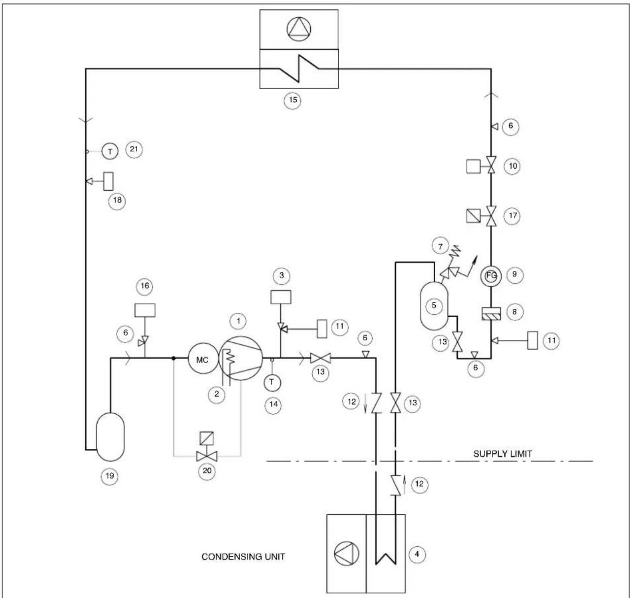
flowchart
graph TD
    A["15"] --> B["6"]
    B --> C["10"]
    C --> D["17"]
    D --> E["FG"]
    E --> F["9"]
    F --> G["8"]
    G --> H["11"]
    H --> I["6"]
    I --> J["5"]
    J --> K["13"]
    K --> L["12"]
    L --> M["4"]
    M --> N["CONDENSING UNIT"]
    O["T"] --> P["21"]
    Q["18"] --> R["16"]
    S["19"] --> T["MC"]
    U["20"] --> V["2"]
    W["3"] --> X["T"]
    Y["11"] --> Z["6"]
    AA["12"] --> AB["13"]
    AC["14"] --> AD["13"]
    AE["16"] --> AF["6"]
    AG["17"] --> AH["17"]
    AI["18"] --> AJ["18"]
    AK["19"] --> AL["19"]
| POS. DESCRIPTION | |
| 1 | Capacity modulating compressor |
| 2 | Crankcase heater |
| 3 | High pressure switch (HP) |
| 4 | Air cooled condenser |
| 5 | Liquid receiver |
| 6 | Access valve |
| 7 | Safety valve |
| 8 | Filter dryer |
| 9 | Sight glass |
| 10 | Electric expansion valve |
| 11 | Pressure transducer for condensing control |
| POS. DESCRIPTION | |
| 12 | Check valve (mandatory) |
| 13 | Shut-off valve |
| 14 | Safety thermostat (for X13UA only) |
| 15 | Evaporator |
| 16 | Low pressure switch (LP) |
| 17 | Shut-off solenoid valve |
| 18 | Pressure transducer for expansion valve |
| 19 | Suction accumulator |
| 20 | Capacity modulating solenoid valve |
| 21 | Temperature sensor for expansion valve |
Fig. 2 XDFN XxxUW

flowchart
graph TD
    A["COOLING WATER INLET"] --> B["COOLING WATER OUTLET"]
    B --> C["MC"]
    C --> D["T"]
    D --> E["15"]
    E --> F["FG"]
    F --> G["10"]
    G --> H["6"]
    H --> I["11"]
    I --> J["8"]
    J --> K["7"]
    K --> L["5"]
    L --> M["13"]
    M --> N["6"]
    N --> O["4"]
    O --> P["20"]
    P --> Q["2"]
    Q --> R["19"]
    R --> S["16"]
    S --> T["6"]
    T --> U["14"]
    U --> V["3"]
    V --> W["6"]
    W --> X["1"]
    X --> Y["1"]
    Y --> Z["21"]
    Z --> AA["18"]
| POS. DESCRIPTION | |
| 1 | Capacity modulating compressor |
| 2 | Crankcase heater |
| 3 | High pressure switch (HP) |
| 4 | Water cooled condenser |
| 5 | Liquid receiver |
| 6 | Access valve |
| 7 | Safety valve |
| 8 | Filter dryer |
| 9 | Sight glass |
| 10 | Electric expansion valve |
| 11 | Pressure transducer for condensing control |
| POS. DESCRIPTION | |
| 12 | Check valve |
| 13 | Shut-off valve |
| 14 | Safety thermostat (for X13UW only) |
| 15 | Evaporator |
| 16 | Low pressure switch (LP) |
| 17 | Condensing pressure control water valve |
| 18 | Pressure trasducer for expansion valve |
| 19 | Suction accumulator |
| 20 | Capacity modulating solenoid valve |
| 21 | Temperature sensor for expansion valve |
Fig. 3 XDFN XxxUC

flowchart
graph TD
    A["Chilled Water Outlet"] --> B["Valve ①"]
    B --> C["Valve ②"]
    C --> D["Valve ③"]
    D --> E["Valve ④"]
    style A fill:#f9f,stroke:#333
    style B fill:#ccf,stroke:#333
    style C fill:#cfc,stroke:#333
    style D fill:#fcc,stroke:#333
    style E fill:#cff,stroke:#333
| POS. Standard components | |
| 1 | Chilled water coil |
| 2 | Chilled water 3—way valve |
| 3 | Manual bleed valve |
| 4 | Water temperature sensor |
Fig. 1 Air conditioner electrical power supply (400V–3ph–50 Hz + N + EARTH)

Fig. 2 Rack electrical power supply (230V-1ph-50 Hz + EARTH)
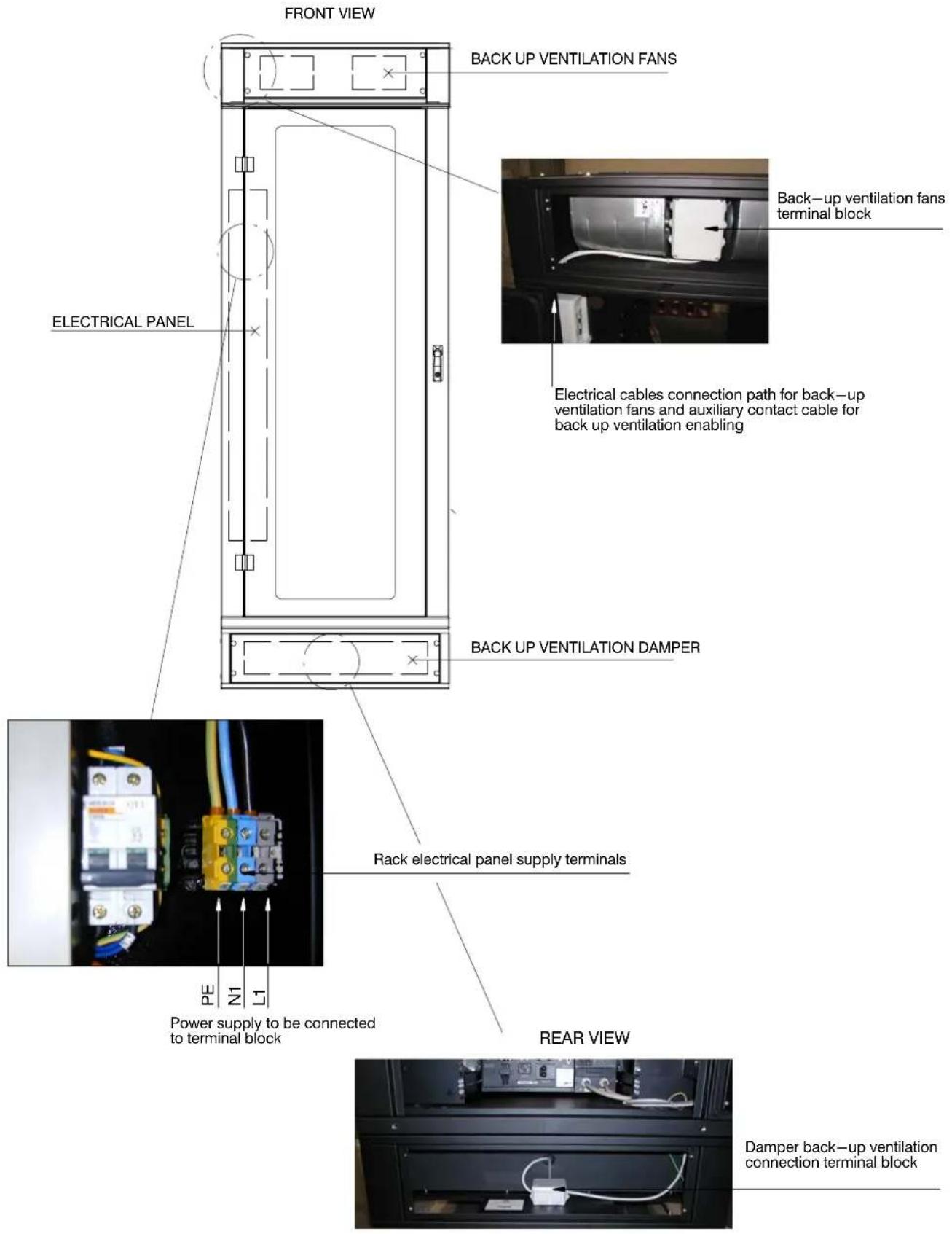
Fig. 3 Rack electrical panel location
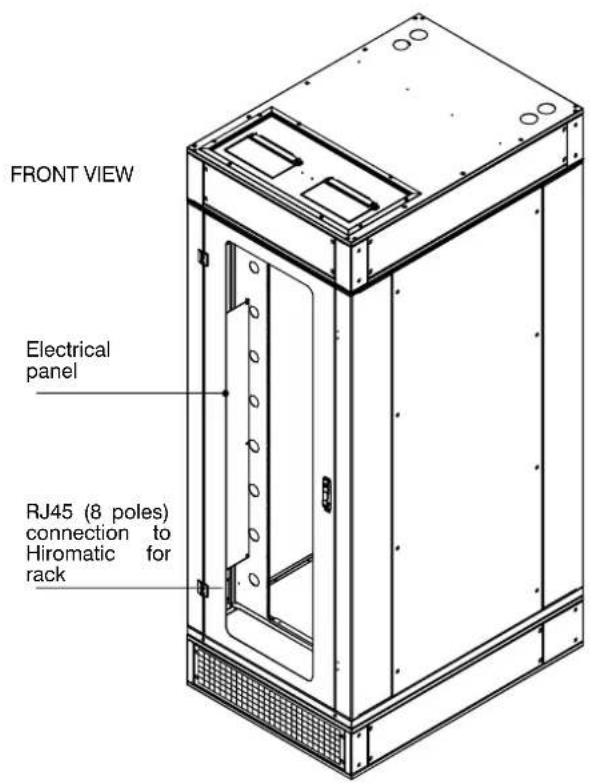
Fig. 4 Rack power strips and PDU location (optional)
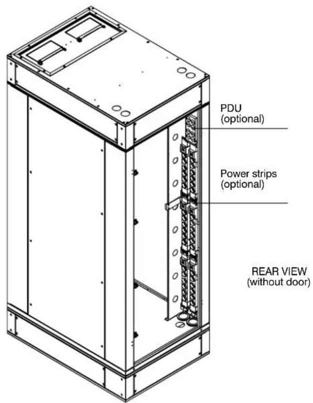
Fig. 5 Rack smoke warning sensor (optional) location

Fig. 1 Air conditioner column

Fig. 2 Rack unit

Fig. 1 Standard packing
Air conditioner / Rack
with or without base module
Fig. 2 Standard packing Plenum and/or Base module

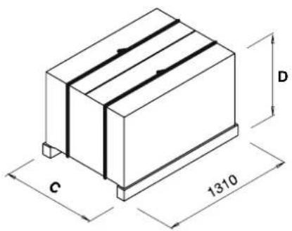
Tab. a — Available packages following the required configuration. — Dimensions
| DESCRIPTION – Re. Fig.^1 | Dimensions (mm) | |
| A | B | |
| Air Conditioner (X...) and Conditioner Base Module (CBM) connected together | 820 2325 | |
| Air Conditioner (X...) | 820 2100 | |
| Air Conditioner (X...), Base Module (CBM) and Conditioner Top Plenum (CTP) connected together | 820 2550 | |
| Rack (RAC) and Rack Base Module (RBM) connected together | 920 2325 | |
| Rack (RAC) | 920 2100 | |
| Rack (RAC), Rack Base Module (RBM) and Rack Top Plenum (RTP) connected together | 920 2550 | |
| DESCRIPTION – Re.FFig?2 | Dimensions (mm) | |
| C | D | |
| Conditioner Top Plenum (CTP) | 820 270 | |
| Conditioner Top Plenum (CTP) and Conditioner Base Module (CBM) | 820 620 | |
| Rack Top Plenum (RTP) | 920 270 | |
| Rack Top Plenum (RTP) and Rack Base Module (RBM) | 920 620 | |
TheManufacturerherebydeclaresthatthisproductconformstotheEuropeanUniondirectives:
Emerson Network Power EMEA Liebert Hiross Headquarters
Via Leonardo da Vinci, 16/18
www.eu.emersonnetworkpower.com
marketing.emea@emersonnetworkpower.com
Emerson Network Power EMEA Global Service
Via Leonardo da Vinci, 16/18
service.emea@emersonnetworkpower.com
Emerson Network Power in EMEA
Emerson Network Power GesmbH Austria
Handelskai 102-112 - 1200 Wien
tel. +43 1331890 fax +43 1331892450
Emerson Network Power and Liebert HIROSS - Czech Rep.
Emerson Network Power Sp z.o.o. Poland
Emerson Network Power Russian Rep.Office
Letnikovskaya str., 10, build 2 - 115114,
Moscow
tel.+7 (095) 981 98 11 fax+7 (095) 981 98 14
Emerson Network Power SA Spain
Eduardo Torroja, 23
Poligono Ind. Leganes
28914 Leganes - Madrid
tel. +34 91 4957700 fax + 34 9149578 49
Emerson Network Power AG Switzerland
Raeffelstrasse 29 - 8045 Zürich
tel. +41 1 456 50 60
fax +41 1 456 50 70
Emerson Network Power Ltd United Kingdom
Fourth Avenue, Globe Park - Marlow
Buckinghamshire SL71YG
tel. +44 1628 403200
fax +44 1628 403203
Emerson Network Power.
The global leader in enabling business-critical continuity.
www.eu.emersonnetworkpower.com
marketing.emea@emersonnetworkpower.com
AC Power Systems
Connectivity
DC Power Systems
Embedded Power
Integrated Cabinet Solutions
Outside Plant
Power Switch & Control
Precision Cooling
Services
Site Monitoring
Surge & Signal Protection
- SERVICE MANUAL
- Caution
- We recommend that:
- Liebert.
- Digit Configuration
- Air conditioner
- Size:
- Air distribution
- Digit 6 - Fan
- Digit 7 – Main Power Supply
- Digit 8 - Front door and base module
- Digit 9 – Humidification
- Digit 10 - Cooling module configuration
- Digit 11 - Monitoring
- Digit 12 - Top plenum
- Digit 13 - Refrigerant
- Digit 14 – Fire detection and extinguishing
- Digit 15 - Condensing control
- Digit 16 - Packing
- Digit 17 – Special Requirements
- Base module air conditioner
- Top plenum air conditioner
- Notes
- Rack
- Digit 4 - Front door and configuration
- Digit 6 – Fire Detection and extinguishing
- Digit 7 - UPS Inside
- Digit 8 – Power distribution unit (PDU) & Power strip 0 None
- Digit 9 – Monitoring
- Digit 10 - UPS Web Card
- Digit 15 – Special Requirements
- Base module rack
- Digit 1, 2 and 3
- Digit 4 – Backup Ventilation single phase / 230 V
- Digit 5 - Free
- Digit 6 – Special Requirements
- Top plenum rack
- Index
- - Preliminary operations .... 1
- - Operating range ...... 1
- - Positioning 2
- - Installation .... 3
- - Refrigeration connections .... 3
- - Water connections ...... 6
- - Electrical connections 8
- - Cooling module start-up 9
- - XDFN complete system start-up 10
- - Cooling module operation....11
- - Cooling module calibrations & regulation (at start-up) 12
- - Maintenance/Spare Parts 13
- Enclosures
- HUMIDAIR humidifier ...... A - 1
- Technical data tables B-1
- Installation drawings C-1
- Refrigerant and hydraulic connections D - 1
- Refrigeration and hydraulic circuits E-1
- Electrical connections ...... F - 1
- Maintenance G-1
- Packing H-1
- – Preliminary operations
- - Packing (see Fig. 1 - Enclosures H)
- - Special packing (options)
- - Inspection
- - Handling
- – Operating range
- - Indoor and outdoor operative limits
- - Storage limits
- - Noise level limits
- – Positioning
- – Installation
- - Base module
- – Refrigeration connections
- – Refrigeration pipeline connections (A version)
- - General layout (Tab. a)
- - Pipe diameter
- – Installing pipelines
- THIS OPERATION IS ESPECIALLY IMPORTANT WHEN HARD COPPER PIPING IS USED.
- - Vacuum creation and refrigerant charge
- - R407C precharge (A version)
- NEVER USE THE COMPRESSOR TO CREATE A VACUUM (THIS INVALIDATES ITS GUARANTEE).
- - Refrigerant charge (A version)
- - Refrigeration circuits
- – Water connections
- – General warnings
- - Water connections
- - Condensate drain (Fig. g):
- - Cooling water connections (W only)
- - Notes for open circuit applications
- - Notes for closed circuit applications
- - Adding ethylene glycol (W only)
- NOTES:
- – Electrical connections
- - Cooling module (see Fig. 1 - Enclosures F)
- - Power input
- - Electrical connections
- - Protection degree IP2x check
- - Protective features of EC fan
- - Rack module (see Fig. 2, Fig. 3 and Fig. 4 - Enclosures F)
- - Power input
- - Rack electrical panel
- - PDU power limitations (see Fig. 4 - Enclosures F)
- - Power strip limitations (see Fig. 4 - Enclosures F)
- - Smokestat (see Fig. 5 - Enclosures F)
- - Mutual connections between Cooling and Rack Module
- – Safety warnings and Standards
- – Cooling module start—up
- - First start-up (or after long standstill)
- - Starting and stopping
- — Checking the refrigeration piping pressure drops
- – XDFN complete system start-up
- - Rack 42 U's space management
- - First start-up
- move the bridges N1–N8 and R1–R8, and connect the terminals R8–N8–PE (230Vac 50Hz) to the UPS.
- - Starting and stopping
- — Suggested main checkup
- - Cooling module operation
- •COOLING
- •HEATING
- - DEHUMIDIFICATION - optional
- – Cooling module calibrations & regulation (at start—up)
- - Setting the Electric Expansion Valve
- - Valve setting
- - Controller setting
- - Running modes
- - New settings
- – Environment protection
- – Maintenance/Spare Parts
- - Safety instructions
- - Kit Hiromatic evolution L1 for Rack module (see Fig. 2 - Enclosures G)
- - Spare parts
- - Maintenance schedule
- 12.5---Refrigerationcircuit
- WHENREPAIRINGTHEREFRIGERATIONCIRCUIT COLLECTALLREFRIGERANTINACONTAINER:DO NOTALLOWITTOESCAPE.
- 12.5.2---OilchargeR407C
- Theoiltobeusedwhentoppingup(onlyifthereareany leaks) is EMKARATE RL 32–3MA or Mobil EAL Arctic 22CC(seeTab.fandTab.g).
- 12.5.3---OilchargeR22
- Theoiltobeusedwhentoppingup(onlyifthereareany leaks)isSUNISO3GS.
- ---Dismantlingtheunit
- - Regulation (EC) no. 842/2006 (F-gas)
- Stationaryairconditioning, refrigeration, heatpump equipments and stationaryfireprotection systems, placed into the European Community market and operating with fluorinated greenhouse gases (f -- gas), such as R407C, R134a, R410A, they havetocomply with the F - gas Regulation (applied since 04 July 2007).
- App. A – HUMIDAIR humidifier
- A.1 - Preface
- A.2 - Installation
- A.3 - Humidair components
- A.4 - Start-up and operation
- A.4.1 - Start-up
- A.4.2 - Operation
- Note
- A.5 - Maintenance
- A.5.1 - Removing the steam cylinder
- A.5.2 - Replacing the steam cylinder
- A.5.3 – Annual maintenance
- ATTENTION
- A.6 - Humidifier spare part list
- NOTE:
- Space requirement (one)
- Space requirement (two)
- Space requirement (three)
- Building the system (one)
- Building the system (two)
- Building the system (three)
- Building the system (four)
- Emerson Network Power EMEA Liebert Hiross Headquarters
- Emerson Network Power EMEA Global Service
- Emerson Network Power in EMEA
- Emerson Network Power GesmbH Austria
- Emerson Network Power and Liebert HIROSS - Czech Rep.
- Emerson Network Power Sp z.o.o. Poland
- Emerson Network Power Russian Rep.Office
- Emerson Network Power SA Spain
- Emerson Network Power AG Switzerland
- Emerson Network Power Ltd United Kingdom
- Emerson Network Power.
Brand : Emerson
Model : Liebert XDFN
Category : Computer Cooling System