
Skeleton - Desktop Computer ANTEC - Free user manual and instructions
Find the device manual for free Skeleton ANTEC in PDF.


| Product Type | Open Case Desktop Computer |
| Brand | Antec |
| Model | Skeleton |
| Color | Metallic Silver |
| Dimensions (H x W x D) | 13 x 4.8 x 16.5 inches (33.02 x 37.6 x 41.9 cm) |
| Weight | 15.5 lbs (7 kg) |
| Motherboard Support | Mini-ITX, MicroATX, Standard ATX |
| Power Supply | Not included (recommended: Antec Signature, TruePower Quattro, or NeoPower) |
| Cooling System | 1 x Super Big Boy 250mm Multi-LED Fan (adjustable speed, 9 LED settings); 1 x 92mm Hard Drive Fan |
| Drive Bays | 2 x 5.25" Quick Release; 2 x 3.5" Quick Release; 4 x Externally Mounted 3.5" Bays |
| Front I/O Ports | 2 x USB 2.0, 1 x eSATA, 1 x IEEE 1394 FireWire, AC'97/HD Audio In & Out |
| Expansion Slots | 3-way SLI ready (supports up to three 11" PCI-E graphics cards) |
| Construction | Open-air design with removable component tray and motherboard tray, frame side screens |
| Carrying Handles | Integrated grips on top side rails |
| Safety Precautions | Keep away from liquids, pets, and children; do not carry by PCI holder |
| Maintenance | Clean with dry cloth; avoid liquid cleaners near open components |
| Spare Parts / Repairability | Fans and mounting plates replaceable; contact Antec support for parts |
Frequently Asked Questions - Skeleton ANTEC
User questions about Skeleton ANTEC
0 question about this device. Answer the ones you know or ask your own.
Ask a new question about this device
Download the instructions for your Desktop Computer in PDF format for free! Find your manual Skeleton - ANTEC and take your electronic device back in hand. On this page are published all the documents necessary for the use of your device. Skeleton by ANTEC.
USER MANUAL Skeleton ANTEC
SKELETON
User's Manual
Table of Contents
Introduction
1.1 Case Specifications.... 2
1.2 Diagram.... 2
1.3 How to Carry the Skeleton.... 3
Hardware Installation Guide
2.1 Removing/Replacing the Component Tray.... 3
2.2 Removing the Motherboard Tray 4
2.3 Motherboard Installation.... 4
2.4 Removing the Frame Side Screen Panels.... 5
2.5 Power Supply Installation.... 5
2.6 5.25" Quick Release Device Installation.... 6
2.7 3.5" Quick Release Device Installation.... 6
2.8 3.5" Device Frame-Mounted Installation.... 7
2.9 PCI Card Mounting Bar Installation.... 7
Connecting the Front I/O Ports
3.1 USB 2.0 Ports....8
3.2 eSATA Port 8
3.3 IEEE 1394 Port....8
3.4 AC'97 / HD Audio Ports.... 9
3.5 Power Switch / Reset Switch /
Hard Disk Drive LED Connectors.... 9
Cooling System
4.1 The Super Big Boy 250mm Multi-LED Fan.... 10
4.2 92 mm Hard Drive Fan.... 10
4.3 Removing the 92mm Hard Drive Fan.... 11
At Antec, we continually refine and improve our products to ensure the highest quality. As such, it's possible that your new case may differ slightly from the description in this manual. This isn't a problem; it's simply an improvement. As of the date of publication, all features, descriptions, and illustrations in this manual are correct.
Disclaimer
This manual is intended only as a guide for Antec's Computer Enclosures. For more comprehensive instructions on installing the motherboard and peripherals, please refer to the user's manuals that come with those components.
SKELETON User's Manual THINK BEYOND THE BOX
Introduction
The innovative Skeleton case by Antec is designed with an open-air system in mind, giving you the freedom to design your ideal computing solution without the usual limitations that come with a standard enclosure. This enclosure consists of two major parts – the Component Tray and the Frame. The Component Tray is the main structure holding motherboard, 5.25" devices, HDD and power supply. It can slide in and out from the Frame for component installation.
The Skeleton comes without a power supply. Make sure you choose a power supply that is compatible with your computer components. We recommend our Signature, TruePower Quattro, or NeoPower power supplies for the latest ATX specification compliance, broad compatibility, and power savings capability.
The Antec Skeleton is 3-way SLI ready, meaning that you have enough space in your enclosure to install up to three 11" PCI-E graphics cards.
At Antec, we continually refine and improve our products to ensure the highest quality. As such, your new case may differ slightly from the description in this manual. This isn't a problem; it's simply an improvement. As of the date of publication, all features, descriptions, and illustrations in this manual are correct.
Note: Skeleton comes without any panels or cover. Antec does not recommend that users place any liquid-containing items (drinks, ice cream, candles, coffee, perfume, etc.) near it. It is highly recommend that you keep your pets or children away from it.
1.1 Case Specifications
| Case Type Open Case | Design |
| Color Metallic Silver | |
| Dimensions 13"(H) x | 4.8"(W) x 16.5"(D)33.02 (H) x 37.6 cm (W) x 41.9 cm (D) |
| Weight 15.5 lbs / 7 kg | |
| Cooling 1 x Super Big | Boy 250mm Multi-LED Fan1 x 92mm Hard Drives Fan |
| Drive Bays 2 x Quick | Release 5.25" Bays2 x Quick Release 3.5" Bays4 x Externally Mounted 3.5" Bays |
| Motherboard Size Mini | -ITX, MicroATX, Standard ATX |
| Front I/O Panel 1 x IEEE | EE 1394 Firewire2 x USB 2.01 x eSATAAC'97/HD Audio In and Out |
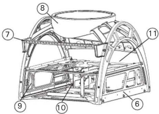
1.2 Diagram
- Super Big Boy 250mm Multi-LED Fan
- Front panel switches and I/O module
- 2 x 5.25" Quick Release Drive Bays
- 92mm Hard Drives Cooling Fan
- 2 x 3.5" Quick Release Drive Bays
- Removable Frame Side Screens
- Removable PCI Mounting Bar
- 250mm Fan Speed and LED switches
- Removable Component Tray / Tray thumb screws
- Power Supply mount
- Removable Motherboard Tray

1.3 How to Carry the Skeleton

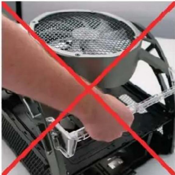
The Skeleton case is designed to be held by either set of grips on the top of the side railing. Use these handles when moving or transporting your case.
Do not carry the case by the plastic PCI holder, as it was not designed to be a load-bearing device.
Hardware Installation Guide
This manual is not designed to cover CPU, RAM, or expansion card installation. Please consult the motherboard manual for specific mounting instructions and troubleshooting. Before proceeding, check the manual for your CPU cooler to find out if there are steps you must take before installing the motherboard. While installing hardware, keep the Skeleton on a flat, stable surface.
2.1 Removing/Replacing the Component Tray


While facing the rear of the case, remove both of the Component Tray Screws on the inside of the Component Tray.
-
Pull back on the rear of the Component Tray until it slides out of the Frame. The Component Tray will slide out about three-quarters of the way.
-
To completely remove the Component Tray from the Frame, find the release tab on the lower left side of the Component Tray when the Tray is fully extended. Press it upwards, then pull the Tray out and completely free of the Frame.
- To replace the Component Tray in the Frame, align the Tray with the back of the case, and slide it forward. Once completely inserted, replace the Component Tray screws along the inside of the Component Tray.
2.2 Removing the Motherboard Tray
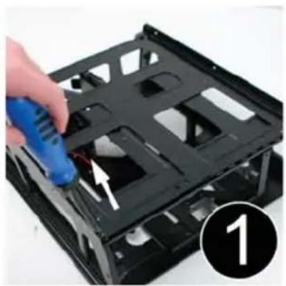


Remove the Component Tray from the Frame as detailed in section 2.1.
- Remove the two screws holding the removable Motherboard Tray to the top of the Component Tray.
- Remove the Motherboard Tray and place it on a flat, stable surface.
- To replace the Motherboard Tray, slide the Motherboard Tray onto the top of the Component Tray from the front such that the tray clips underneath the Component Tray clips. Secure the Motherboard Tray in place with the provided screws.
2.3 Motherboard Installation


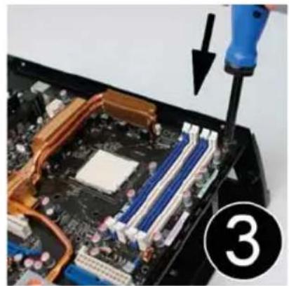
Remove the Component Tray from the Frame and the Motherboard Tray from the Component Tray as detailed in sections 2.1 and 2.2.
- Line up the motherboard with the standoff holes on the Motherboard Tray. Determine which holes line up and remember where they are. Not all mother-boards will match with all of the provided screw holes, and this is not necessary for proper functionality. Some standoffs may be pre-installed for your convenience.
-
Lift up and remove the motherboard. Screw in the brass standoffs to the threaded holes that line up with the motherboard.
-
Place the motherboard on the brass standoffs. Screw in the motherboard to the standoffs with the provided Phillips-head screws.
Replace the Motherboard Tray onto the Component Tray, and the Component Tray in the Frame as detailed in sections 2.1 and 2.2.
Note: You do NOT need to install an I/O panel for Skeleton. Your motherboard should come with one. Keep it in a safe place. You will need it if you decide to move your motherboard to a traditional case in future.
2.4 Removing the Frame Side Screen Panels

Removing the screens on either side of the Frame will allow access to the lower level of the Component Tray for power and data cable routing.
- Locate and simultaneously press inward the two tabs on the left and right sides of the screen panel.
- Pull the panel away from the Frame.
2.5 Power Supply Installation
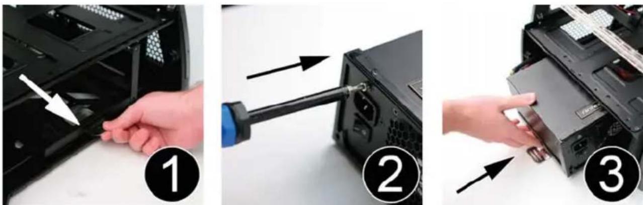
- Remove the power supply mounting plate from the rear of the Component Tray by pulling upward on the metal tab and sliding the plate backward out of the tray.
-
Mount the power supply into the power supply mounting plate with the screws provided.
-
Slide the plate-mounted power supply into the bottom level of the Component Tray until it locks into position. There are two possible locations to mount the power supply, depending on the size of your equipment.
Note: Power supplies equipped with an 80mm fan will draw air through the Skeleton and power supply more effectively. We recommend power supplies such as Antec's TruePower Quattro or Signature series power supplies. However, if using a power supply with a 120mm fan, ensure that the power supply fan will face the top of the case when installed.
2.6 5.25" Quick Release Device Installation
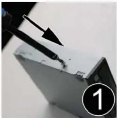

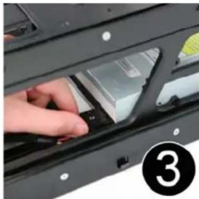
- Find the tool bag marked "For 5.25" device" which contains round, silver-headed screws. Align one of the screws with your 5.25" device. For the upper 5.25" drive bay, fasten the screw to the right side, lower front screw hole. For the lower 5.25" device, fasten the screw to the right side, upper front screw hole.
- While facing the front of the case, insert your 5.25" device into the corresponding slot in the Component Tray until it locks into position.
- Connect the data and power connectors from the motherboard and power supply to the device.
Note: It may be necessary to remove the motherboard tray and/or side screens as detailed in sections 2.2 and 2.3 to effectively route cables to your device.
2.7 3.5" Quick Release Device Installation
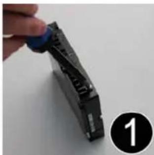
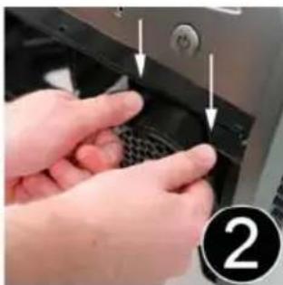

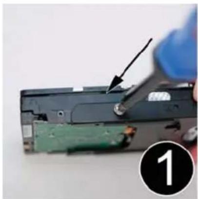
- Find the tool bag marked "For HDD" which contains round, black-headed screws. Fasten one of the screws to your 3.5" device in the front left screw hole.
- While facing the front of the case, depress the two tabs on the top of the 92mm fan casing and detach it from the front of the hard drive housing.
-
Insert your 3.5" device into the corresponding slot until it locks into position, then replace the 92mm fan housing.
-
Connect the data and power connectors from the motherboard and power supply to the device.
Note: It may be necessary to remove the motherboard tray and/or side screens as detailed in sections 2.2 and 2.3 to effectively route cables to your devices.
2.8 3.5" Device Frame-Mounted Installation


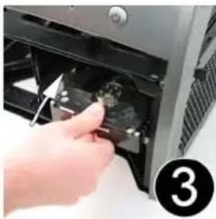
Your Antec Skeleton case has the ability to mount up to four additional 3.5" devices externally on the Frame for additional storage capacity.
- Align your 3.5" device with the included 3.5" device mounting plates and secure them together with the included screws.
- Hook the mounting plate along the sides of the Frame.
- Connect the data and power connectors from the motherboard and power supply to the device.
For extra stability and security, your mounted 3.5" device can be attached to the inside of the screen panels with screws.
Note: It may be necessary to remove the motherboard tray and/or side screens as detailed in sections 2.2 and 2.3 to effectively route cables to your devices.
2.9 PCI Card Mounting Bar installation
The Skeleton includes a PCI card mounting bar to help stabilize your system's PCI cards.
- Align the PCI card mounting bar with the screw holes on the back side of the Frame.
- Mount the bar to the Frame with the screws provided.

Connecting the Front I/O Ports
3.1 USB 2.0 Ports
Connect the front I/O panel USB cable to the USB header pin on your motherboard. Check the motherboard manual to ensure that it matches the table below:
Motherboard USB Pin Layout
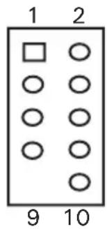
| Pin Signal Names Pin Signal Names | |||
| 1 | USB Power 1 | 2 | USB Power 2 |
| 3 | Negative Signal 1 | 4 | Negative Signal 2 |
| 5 | Positive Signal 1 | 6 | Positive Signal 2 |
| 7 | Ground 1 | 8 | Ground 2 |
| 9 | Key (No Connection) | 10 | Empty Pin |
Locate the internal USB connector on your motherboard and connect the corresponding cable.
3.2 eSATA Port
Connect the front I/O panel SATA cable to a standard SATA connector on your motherboard.
3.3 IEEE 1394 Port
Connected to the Skeleton front I/O panel there is an Intel ® standard 10-pin connector. The pin assignments for these connectors are as follows:
Pin Assignment for Front Panel IEEE 1394 Connector

| Pin Signal Names Pin Signal Names | |||
| 1 TPA + 2 TPA- | |||
| 3 Ground 4 Ground | |||
| 5 TPB + 6 TPB- | |||
| 7 + 12V (Fused) 8 + 12V (Fused) | |||
| 9 Key (No Pin) 10 Ground | |||
Locate the internal IEEE 1394 connector on your motherboard and connect the corresponding cable.
3.4 AC'97/HD Audio Ports
Connected to your front I/O panel there is an Intel® standard 10-pin AC'97 connector and an Intel® 10-pin HDA (High Definition Audio) connector. The pin assignments for these connectors are as follows:
Pin Assignment for Audio Ports (HDA and AC'97)
| Pin Signal Names(HDA) | Pin Signal Names(AC'97) |
| 1 MIC2 L 1 MIC In | |
| 2 AGND 2 GND | |
| 3 MIC2 R 3 MIC Power | |
| 4 AVCC 4 NC | |
| 5 FRO-R 5 Line Out (R) | |
| 6 MIC2_JD 6 Line Out (R) | |
| 7 F_IO_SEN 7 NC | |
| 8 Key (no pin) 8 Key (no pin) | |
| 9 FRO-L 9 Line Out (L) | |
| 10 LINE2_JD 10 | Line Out (L) |
You can connect either the AC'97 or the HDA connector, but not both at once, to your motherboard depending on the spec of the motherboard. Locate the internal audio connectors from your motherboard or sound card and connect the corresponding audio cable. Consult your motherboard or sound card manual for the pin-out positions.
3.5 Power Switch / Reset Switch / Hard Disk Drive LED Connectors


Connected to the front of the Skeleton case Frame are LED and switch leads for power, reset, and HDD LED activity. Attach these to the corresponding connectors on your motherboard. Consult your motherboard manual for specific pin positions. For LEDs, colored wires are positive (+). White or black wires are negative (−). If the LED does not light up when the system is powered on, try reversing the connection. For more info on connecting LEDs to your motherboard, see your motherboard manual.
Note: There is no Power LED in this case. The illuminated case fans will turn on when there is power to the computer.
Cooling System
4.1 The Super Big Boy 250mm Multi-LED Fan
The Skeleton's unique and innovative open case design provides that only one Super Big Boy 250mm Multi-LED fan is required to cool most of your system components. This overhead fan is adjustable, allowing you to choose the best speed suited to your needs. The fan speed switch is located at the top rear of the case near the fan. The default speed is Low.
The Super Big Boy 250mm fan also includes six multi-colored LED lights, and can be set to color oscillation, one-color lighting, off and more (nine settings total). The LED switch is located next to the fan speed switch at the top rear of the case.
250 mm fan specifications:
Rated Voltage: DC 12V
Operating Voltage: 10.8V - 13.2 V
| Speed RPM | Input Current | Air Flow | Static Pressure | Acoustical Noise | Input Power | |
| High 800 | 0.45A (Max.) | 157.856CFM | 0.046 inch 2 CH3 | 2 dBA 5.4 W | ||
| Medium 600 | 0.3A 11 | 8.392 CFM 0.02 | 6 inch-H | 2 O 2 | 6 dBA 3.6 W | |
| Low 400 | 0.2A 78 | 9.28 CFM 0.01 | 2 inch-H | 2 O 1 | 7 dBA 2.4 W | |
4.2 92 mm Hard Drives Fan
The Skeleton's integrated 92 mm fan on the front of the Component Tray cools your installed hard drives quietly and efficiently. This fan is attached directly to the hard drive cage and is designed to blow air directly into the HDDs.
92 mm fan specifications:
Rated Voltage: DC 12V
Operating Voltage: 10.8V-13.2V
| Speed RPM | Input Current | Air Flow | Static Pressure | Acoustical Noise | Input Power |
| 1100 | 0.08A (Max.) | 15.6CFM | 0.014 in2Ch-1 | 2.7 dBA 0.96 | W |
4.3 Removing the 92 mm Hard Drive Fan


Ensure that the fan power cable is disconnected before removing the fan.
-
While facing the front of the case, depress the two tabs on the top of the 92mm fan and detach it from the front of the hard drive housing.
-
Remove the four screws on the front of the fan casing.
-
Pull the fan out of the fan housing.
Antec, Inc.
47900 Fremont Blvd.
Fremont, CA 94538
USA
tel: 510-770-1200
fax: 510-770-1288
Antec Europe B.V.
Stuttgartstraat 12
3047 AS Rotterdam
The Netherlands
tel: +31 (0) 10 462-2060
fax: +31 (0) 10 437-1752
Customer Support:
US & Canada
1-800-22ANTEC
customersupport@antec.com
Europe
+31 (0) 10 462-2060
europe.techsupport@antec.com
www.antec.com



- SKELETON
- USER'S MANUAL
- TABLE OF CONTENTS
- INTRODUCTION
- HARDWARE INSTALLATION GUIDE
- CONNECTING THE FRONT I/O PORTS
- COOLING SYSTEM
- DISCLAIMER
- SKELETON USER'S MANUAL THINK BEYOND THE BOX
- 1.1 CASE SPECIFICATIONS
- 1.2 DIAGRAM
- 1.3 HOW TO CARRY THE SKELETON
- 2.1 REMOVING/REPLACING THE COMPONENT TRAY
- 2.2 REMOVING THE MOTHERBOARD TRAY
- 2.3 MOTHERBOARD INSTALLATION
- 2.4 REMOVING THE FRAME SIDE SCREEN PANELS
- 2.5 POWER SUPPLY INSTALLATION
- 2.6 5.25" QUICK RELEASE DEVICE INSTALLATION
- 2.7 3.5" QUICK RELEASE DEVICE INSTALLATION
- 2.8 3.5" DEVICE FRAME-MOUNTED INSTALLATION
- 2.9 PCI CARD MOUNTING BAR INSTALLATION
- 3.1 USB 2.0 PORTS
- 3.2 ESATA PORT
- 3.3 IEEE 1394 PORT
- 3.4 AC'97/HD AUDIO PORTS
- 3.5 POWER SWITCH / RESET SWITCH / HARD DISK DRIVE LED CONNECTORS
- 4.1 THE SUPER BIG BOY 250MM MULTI-LED FAN
- 4.2 92 MM HARD DRIVES FAN
- 4.3 REMOVING THE 92 MM HARD DRIVE FAN
Brand : ANTEC
Model : Skeleton
Category : Desktop Computer