
Powerware 9355-15-N-15-64x9Ah - Uninterruptible power supply EATON - Free user manual and instructions
Find the device manual for free Powerware 9355-15-N-15-64x9Ah EATON in PDF.


| Product Type | Uninterruptible Power Supply (UPS) |
| Model | Powerware 9355-15-N-15-64x9Ah |
| Manufacturer | Eaton |
| Rated Power | 15 kVA / 13.5 kW |
| Input Voltage | 3-phase, 380/400/415 V |
| Output Voltage | 3-phase, 380/400/415 V (adjustable) |
| Battery Type | Valve-Regulated Lead-Acid (VRLA) |
| Battery Configuration | 64 x 9 Ah (internal batteries) |
| Topology | Double conversion online |
| Display | LCD with status indicators |
| Communication Ports | RS-232, USB, SNMP slot |
| Dimensions (H x W x D) | 1700 x 500 x 800 mm |
| Weight | Approximately 200 kg |
| Operating Temperature | 0 °C to 40 °C |
| Protection Features | Overload, short circuit, surge protection |
| Cooling | Forced air with variable speed fans |
| Maintenance | Periodic battery check, clean air filters |
| Spare Parts Available | Battery packs, fan assemblies, control boards |
| Safety Standards | IEC 62040-1, UL 1778 |
| Warranty | Standard 1 year (extendable) |
Frequently Asked Questions - Powerware 9355-15-N-15-64x9Ah EATON
User questions about Powerware 9355-15-N-15-64x9Ah EATON
0 question about this device. Answer the ones you know or ask your own.
Ask a new question about this device
Download the instructions for your Uninterruptible power supply in PDF format for free! Find your manual Powerware 9355-15-N-15-64x9Ah - EATON and take your electronic device back in hand. On this page are published all the documents necessary for the use of your device. Powerware 9355-15-N-15-64x9Ah by EATON.
USER MANUAL Powerware 9355-15-N-15-64x9Ah EATON
©2007 Eaton Corporation
All Rights Reserved
The contents of this manual are the copyright of the publisher and may not be reproduced (even extracts)
unless permission granted.
Every care has been taken to ensure the accuracy of the information contained in this manual, but no liability can be accepted for any errors or omission. The right to make design modifications is reserved.
UPS 8 – 15 kVA, 400 V 50/60 Hz
User's Guide 1023625 revision C
Contents
1. Safety instructions ....4
Audience 4
CE marking 4
User precautions....4
Environment....5
Inquiries....5
2. Mechanical installation....6
Delivery check....6
Unpacking and visual inspection 6
3. Planning before installation....8
4. Cabinet installation....9
Maintenance bypass switch....9
Transformer option 11
External battery cabinet option 12
Battery racks 12
5. Electrical installation....13
Power cables and protective fuses 14
Wiring procedure....15
External Battery Cabinet (EBC) installation procedure 18
6. Software and connectivity....20
Communication cables....20
Connection to the standard RS 232 port (X53)....20
LanSafe software 2
External control connections....21
Emergency Power Off (EPO) 23
Relay outputs....23
Programmable signal inputs....23
XSlot communication (option)....24
SNMP/Web Module (optional) 24
AS400 Relay Module (optional) 25
Single Serial Port Module (optional) 25
Modus/Jbus Module (optional) 25
7. User operations....26
Display functions....20
User Settings 2
Configuring user settings 29
Changing language 29
Changing charging current....29
Using relay outputs 29
Normal start-up 30
Battery start-up 30
Start-up after EPO 30
Shutdown 3
8. Maintenance 32
Regular service/intervals....32
Batteries....32
Cooling fan....3
LED Indicators 33
Maintenance bypass switch (MBS) operation 3
Turn UPS from normal mode to mechanical bypass 34
Turn UPS from mechanical bypass to normal mode 35
9. Parallel systems 37
Overview....3
Tie cabinets 38
XSlot Hot Sync card: installing and wiring 42
Parallel operations....4
10. Recycling the used UPS or batteries 45
11. Dimensional drawings 47
12. Technical data....48
Standards 48
Environment 48
Mechanical configuration 48
Characteristics 48
AC input 49
DC circuit....49
AC output 49
13. Warranty....50
1. Safety instructions
The UPS operates with mains, battery or bypass power. It contains components that carry high currents and voltages. The properly installed enclosure is earthed and IP20 rated against electrical shock and foreign objects. However, only qualified personal is allowed to install and service the UPS.

Warning!
Operations inside the UPS must be performed by a service engineer from the manufacturer or from an agent authorised by the manufacturer.
Do not ever service inside the UPS when mains power is applied or the UPS is in battery mode. Use the optional mechanical bypass if installed to the system. Remember to open battery breaker. Always ensure by measuring with a multi-meter that no dangerous voltages are present.
Audience
The intended audiences of this manual are people who plan the installation, install, commission, and use or service the UPS. The manual provides guidelines to check delivery, installing and commissioning of the UPS.
The reader is expected to know the fundamentals of electricity, wiring, electrical components and electrical schematic symbols. This manual is written for a global reader.

Note!
Read the manual before operating or working on the UPS.
CE marking
The product has the CE marking in compliance with the following European directives:
• LV Directive (Safety) 72/23/EEC and 93/68/EEC
• EMC Directive 89/336/EEC and 93/68/EEC
Declaration of conformity with UPS harmonised standards and directives EN 62040-1-1 (Safety) and EN 50091-2 (EMC) are available on the web site (http://www.powerware.com).
User precautions
The only user operations permitted are:
- Start up and shut down of the UPS, excluding the commissioning start-up.
- Use of the LCD control panel and Maintenance Bypass Switch (MBS)
- Use of optional connectivity modules and their software
The user must follow the precautions and only perform the described operations. Any deviations from the instructions could be dangerous to the user or cause accidental load loss.

Warning!
The user is not permitted to open of any screws excluding connectivity plates and the MBS locking plate. Failure to recognise the electrical hazards could prove fatal.
Environment
The UPS must be installed according to the recommendations in this manual. Under no circumstances the UPS should be installed in an airtight room, in the presence of flammable gases, or in an environment exceeding the specification.
Excessive amount of dust in the operating environment of UPS may cause damage or lead to malfunction. The UPS should be always protected from the outside weather and sunshine. The recommended operating temperature is from +15 to +25 Celsius degrees.
Inquiries
Address any inquiries about the UPS and battery cabinet to the local office or agent authorised by the manufacturer. Please quote the type code and the serial number of the equipment.
2. Mechanical installation
The UPS and accessories are delivered on a specifically designed pallet that is easy to move with a forklift or a pallet jack. Keep the UPS always in upright position and do not drop the equipment. Do not either stack the pallets because of high-energy batteries involved and the heavy weight
Delivery check
The UPS is delivered with the following items:
- Plastic bag containing:
- Quick Installation Guide, paper format, multilingual (coming later)
User's Guide, paper format, multilingual
User's Guide, CD-ROM format, multilingual (coming later)
Residual voltage warning stickers
Software Suite, CD-ROM format, English language
RS-232 serial cable for the Software Suite - Delivery documents
Unpacking and visual inspection
Check that there are no signs of shipping damages. The outside 'Tip&Tel' indicator should be intact if the equipment has been transported in the upright position.

Note!
A claim for shipping damage must be filed immediately and the carrier must be informed within 7 days of receipt of the equipment. The packing materials should be stored for further investigation.
Unpack the equipment by removing the packing and shipping materials. Make a visual inspection and check that the inside 'Drop&Tell' indicator is intact. Make sure that the floor surface is solid and suitable for the wheeling and heavy weight, twist the levelling feet of the unit to up position and remove the equipment from the pallet.
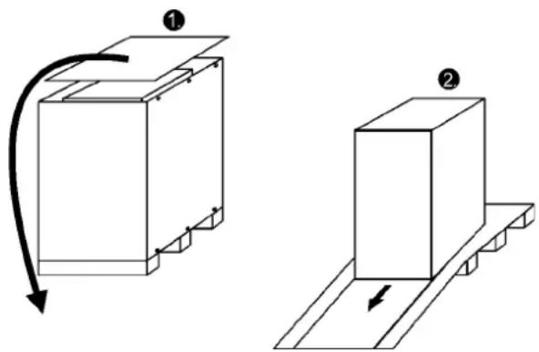
Figure1. Instructions for removing the equipment from the pallet.
Check the information on the type designation label of the equipment to verify that the unit is of the correct type. The type designation label includes ratings, a CE marking, a type code, a part number and a serial number. The serial number is important when making inquiries. It allows individual recognition of the equipment.
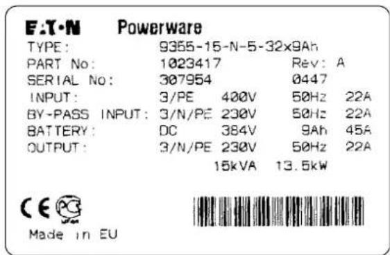
Figure 2. Type designation label.
3. Planning before installation
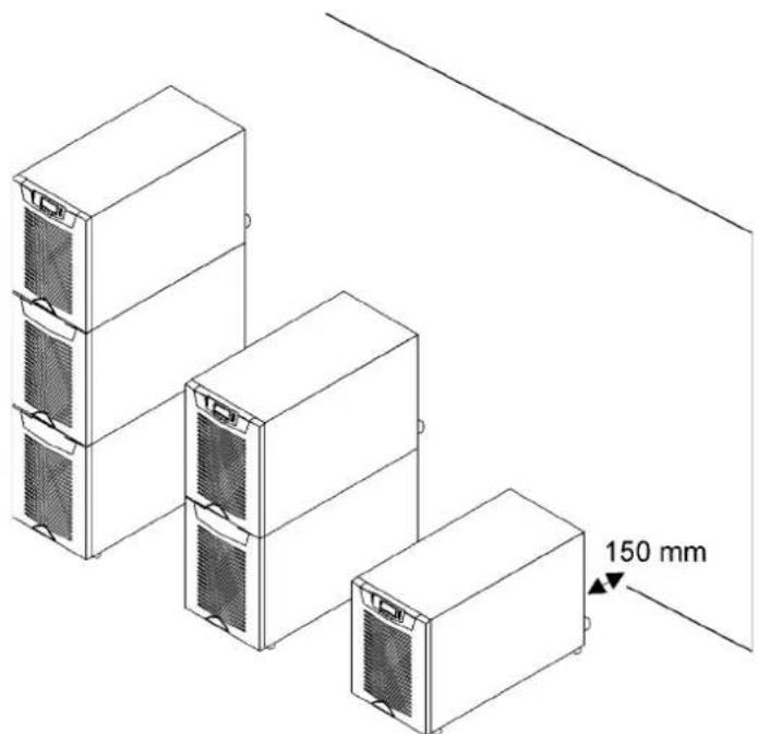
The equipment must be installed in upright position. The equipment requires space to front and back to enable cooling airflow, service and maintenance. All cooling air enters at front and exits at unit rear. The required min. clearance from unit rear to an obstruction is 150 mm.
natural_image
Isometric line drawing of three stacked server units with a 150 mm dimension label (no text or symbols on the devices themselves)Figure 3. Ventilation space around the equipment.
It is required to arrange ventilation of the UPS room. Sufficient amount of air cooling is needed to keep the max. room temperature rise at desired level:
- Temperature rise of max. +5°C requires the airflow of 600 m3 per 1 kW of losses.
- Temperature rise of max. +10°C requires the airflow of 300 m3 per 1 kW of losses.
An ambient temperature of 15 to 25 Celsius degrees is recommended to achieve a long life of the UPS and batteries. The cooling air entering the UPS must not exceed +40 °C. Avoid high ambient temperature, moisture and humidity.
The floor material should be non-flammable and strong enough to support the heavy load. The UPS has (4) leveling feet that should be used when finalising the installation. The diameter of a single leveling foot is 1 inch (25.4 mm).
| Equipment Weight | Point Distributed Note | |||
| UPS+1BAT 165 kg 8 | .25 kg/cm2 786 kg/m2 Batteries installed. | |||
| UPS+2BAT 275 kg 1 | 3.75 kg/cm2 1310 kg/m2 Batteries installed. | |||
| UPS | 60 kg | 3.00 kg/cm2 286 kg/m2 No Batteries. | ||
| UPS+1BAT 75 kg | 3.75 kg/cm2 357 kg/m2 No Batteries installed. | |||
| UPS+2BAT 90 kg | 4.50 kg/cm2 429 kg/m2 No Batteries installed. | |||
| 2BAT | 195 kg 9.75 kg/cm2 929 kg/m2 Batteries installed. | |||
| 3BAT | 310 kg 15.50 kg/cm2 1476 kg/m2 Batteries installed. | |||
Table 4. The floor surface must tolerate these loading.
4. Cabinet installation
The required distance for UPS units next to each other is ten millimetres. The same applies to the optional battery cabinets that should be installed next to the UPS cabinet.
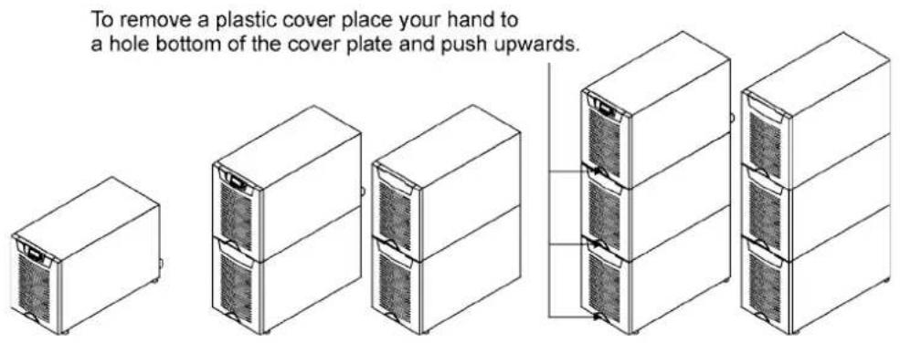
Figure 5. UPS and external battery cabinets.
The UPS family has several alternative battery cabinets and configurations depending on the selected back-up time and quality of batteries.
Maintenance bypass switch
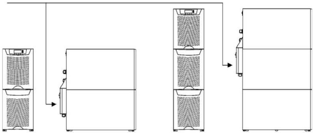
The maintenance bypass switch (MBS) shall be mounted in back of the UPS battery compartment. It can be ordered factory installed.
flowchart
graph TD
    A["Top Unit"] --> B["Refrigeration Tank"]
    B --> C["Storage Unit"]
    C --> D["Recirculation Unit"]
    D --> E["Outlet"]
    style A fill:#f9f,stroke:#333
    style B fill:#ccf,stroke:#333
    style C fill:#cfc,stroke:#333
    style D fill:#fcc,stroke:#333
Figure 6. Instructions for locating the maintenance bypass switch.
Please fix the switch MBS to the wall (din rail) or to the back of the UPS as shown below.
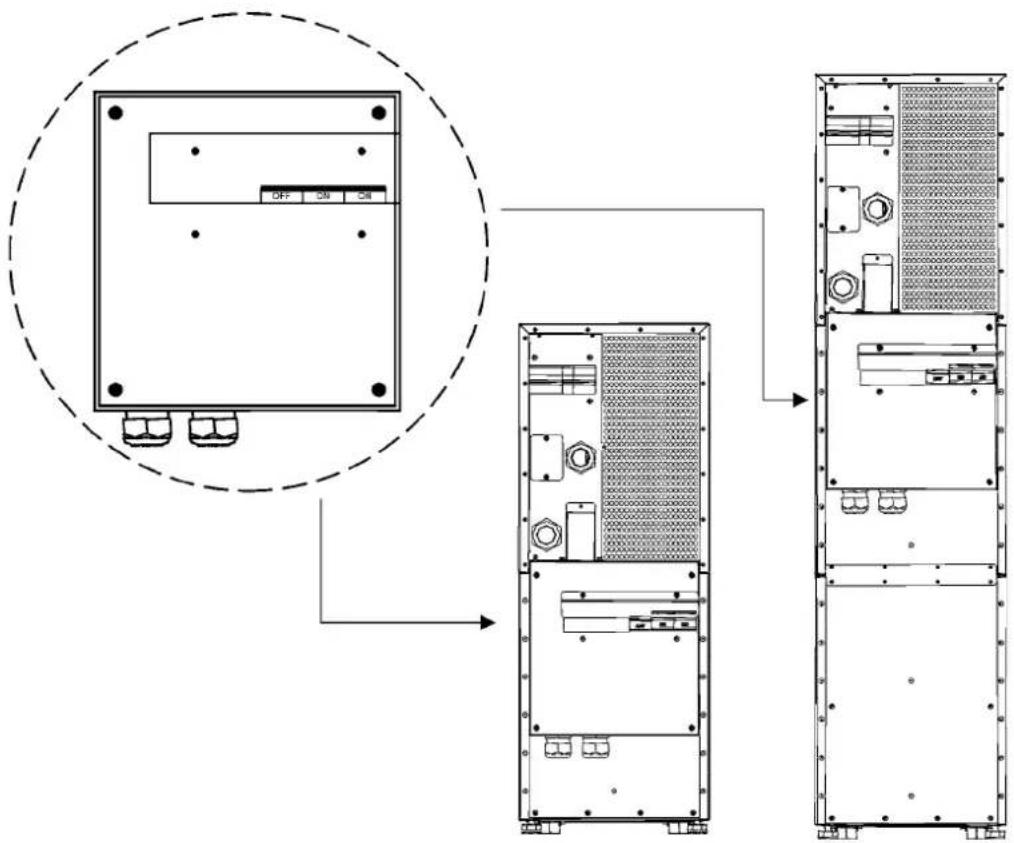
Figure 7. The maintenance Bypass Switch (MBS) when installed in the backside.
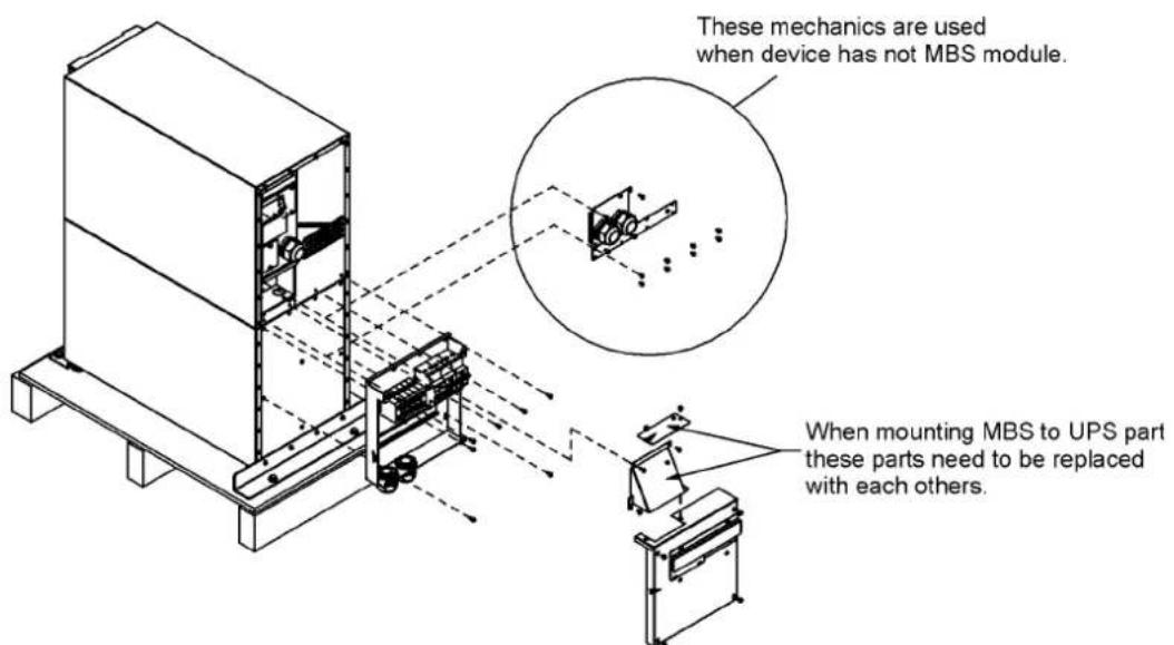
Figure 8. MBS assembly
Transformer option
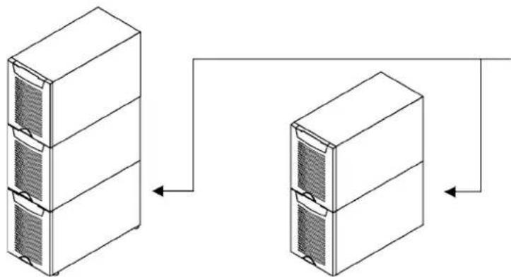
The galvanic isolation transformer can be ordered as factory installed. The transformer is an integral part of the UPS unit. Alternatively the isolation transformer can be purchased as a separate item to upgrade your existing system.
flowchart
graph TD
    A["Server Rack 1"] --> B["Data Flow Arrow"]
    C["Server Rack 2"] --> B
    B --> D["Data Flow Arrow"]
Figure 9. Transformer option can be ordered factory installed (integral) or separately.
The overtemperature sensor cable is connected to the control input (X45 or X44) of the UPS, see the next drawing. In the factory installed systems this cable is ready-made for use.
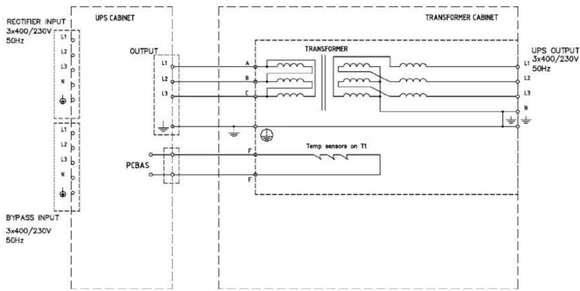
Figure 10. Wiring diagram of the UPS and the external transformer option
External battery cabinet option
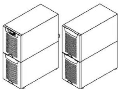
It's recommended to install external battery cabinets next to the UPS unit. The external battery can be placed on either side of the UPS unit. Check before the installation that the battery voltage values in the type plate of the UPS and external battery cabinets are the same. The cables are delivered with the external battery cabinet. See External Battery Cabinet (EBC) installation procedure.

Warning!
The UPS contains high DC voltages. A qualified person must do the connections between the UPS and the external battery cabinet(s). The battery cabinet is connected electrically in parallel with the internal batteries of the UPS.
natural_image
Line drawing of two server rack units with ventilation grilles (no text or symbols)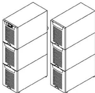
natural_image
Line drawing of two server rack units with heat sinks and ventilation grilles (no text or symbols)Figure 11. UPS and external battery cabinets.
Battery racks
External battery racks shall be sized to take the voltage drop in the cable into account. To obtain support and help contact the local office or agent authorised by the manufacturer.
5. Electrical installation
The customer has to supply the wiring to connect the UPS to the local power source. The electrical installation procedure is described in the following text. The installation inspection and initial start up of the UPS and extra battery cabinet shall be carried out by a qualified engineer with UPS installation experience.

Warning!
Physical injury or death may follow, or damage may occur to the UPS, or the load equipment if these instructions are ignored.
F1 Battery breaker
F2 Rectifier breaker
UPS TERMINALS:
F2 Rectifier input
X1 Bypass input
X2 UPS output
X3 External battery input
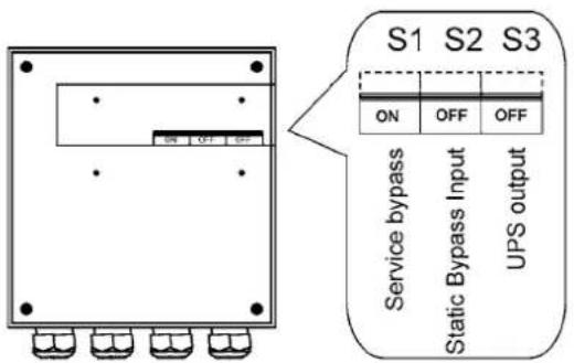
S1 Service Bypass
S2 Static bypass input
S3 UPS output
MBS TERMINALS:
X4 Bypass input
X5 UPS Output
CABLES
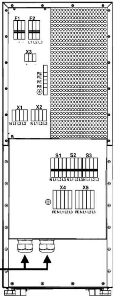
Figure 12. Location of the power terminals.
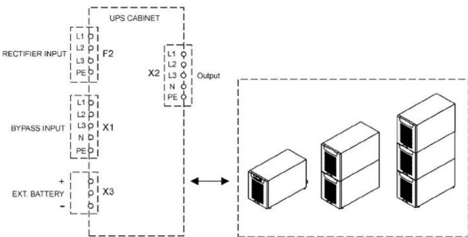
The UPS unit has the following power connections:
Three-phase (L1, L2, L3) and protective earth (PE) connection for the rectifier input
Three-phase (L1, L2, L3), Neutral (N) and protective earth (PE) connection for the bypass input
Three-phase (L1, L2, L3), Neutral (N) and protective earth (PE) connection for the load output
Plus (+), minus (-) and protective earth (PE) connection for the external batteries

Note!
The rectifier requires a Neutral to operate. It's connected internally from the bypass terminal to the rectifier, see wiring diagram.

Note!
Care needs to be taken to ensure that the input supply neutral reference is not disconnected whilst the UPS is in service.
flowchart
graph TD
    A["RECTIFIER INPUT"] --> B["UPS CABINET"]
    C["BYPASS INPUT"] --> B
    D["EXT. BATTERY"] --> B
    B --> E["Output"]
    style A fill:#f9f,stroke:#333
    style C fill:#f9f,stroke:#333
    style D fill:#f9f,stroke:#333
    style B fill:#ccf,stroke:#333
    style E fill:#cfc,stroke:#333
Figure 13. Power terminals found in UPS units.
Power cables and protective fuses
Always use copper cable types to fit terminals with approximately 1.5 Nm torque for different load currents. The Cu cable sizing is based on multi-core cables laid in conduits/trunkings on the wall or on the floor (installation procedure C), ambient temperature 25°C, PVC insulation, surface temperature up to 70°C. Cables of several UPS can be installed in parallel to each other.
Standards SFS 6000-5-52 (2002) and IEC 60364-5-52 (2001-08) "Electrical installations of buildings" with normal 1.7 x Neutral conductor rating for IT loads are used as a sizing guide. For any other conditions, size the cables according to the local safety regulations regarding installation environment, appropriate voltage and currents of the UPS.
Fuses are sized according to local safety regulations, appropriate input voltage and the rated current of the UPS. Therefore, protect the input and bypass cables with gG (gL) fuses or B-C-D type of circuit breakers against overload and short-circuit.
Contact the manufacturer's authorised agent or the local office for assistance at fuse and cable sizing. Refer to the recommended cable and fuse ratings in the below table.
| UPS rating | Input Bypass Load PE | Battery | ||||||||
| Fusing Cable Fusing Cable Cable Cable Cable Fusing | ||||||||||
| 8 kVA | 3-phase | 3x16 A | 4x2.5 mm ^2 | 3x16 A | 4x2.5 mm ^2 | 4x2.5 mm ^2 | 11.6 A | 4 mm ^2 | 10 mm ^2 | 50 A |
| 10 kVA | 3-phase | 3x16 A | 4x2.5 mm ^2 | 3x16 A | 4x2.5 mm ^2 | 4x2.5 mm ^2 | 14.5 A | 4 mm ^2 | 10 mm ^2 | 50 A |
| 3-phase | 3x20 A* | 4x4 mm ^2 | 3x20 A* | 4x4 mm ^2 | 4x4 mm ^2 | 14.5 A | 4 mm ^2 | 10 mm ^2 | 50 A | |
| 12 kVA | 3-phase | 3x25 A | 4x6 mm ^2 | 3x25 A | 4x6 mm ^2 | 4x6 mm ^2 | 17.4 A | 6 mm ^2 | 10 mm ^2 | 50 A |
| 15 kVA | 3-phase | 3x25 A* | 4x6 mm ^2 | 3x25 A* | 4x6 mm ^2 | 4x6 mm ^2 | 21.7 A | 6 mm ^2 | 10 mm ^2 | 50 A |
| 3-phase | 3x32 A | 4x10 mm ^2 | 3x32 A | 4x10 mm ^2 | 4x10 mm ^2 | 21.7 A | 10 mm ^2 | 10 mm ^2 | 50 A | |
| Maximum | 3-phase | 3x63 A | 4x16 mm ^2 | 3x63 A | 4x16 mm ^2 | 4x16 mm ^2 | 16 mm ^2 | 16 mm ^2 | ||
Table 14. Cable and fuse ratings for the different UPS ratings (*With optional limited charging feature at low input and high kW load, see User Settings)
Wiring procedure
The power cable terminals are located in the back of the UPS unit. The service personnel is responsible for the correct electrical installation. They must be authorised by the manufacturer.
The installation procedure:
- Remove the cover(s) of the terminal box of the power cables with a screwdriver. Refer to the dimensional drawing for the correct location at the back of the unit.
- Slide the cables through the grommets of the connection box.
- Connect the conductors of the rectifier and bypass input cables to the proper terminals.
- Connect the conductors of the load cable to the proper terminals.
- Connect the conductors of an external battery cabinet cable to the external battery +, - and PE terminals. Check for the correct polarity. See External Battery Cabinet (EBC) installation procedure.

Warning!
If available, the internal battery has to be disconnected first because the external battery terminals are hazardous due to the parallel battery string.
- Secure the cables with the grommets in the connection box.
- Fasten the cover of the terminal box with a screwdriver.
The IEC/EN 62040-1 safety instructions require the fitting by the user of a warning label on all primary power isolators installed remote from the UPS area. The warning label for electrical maintenance personnel shall carry the following wording or equivalent:
"ISOLATE UNINTERRUBTIBLE POWER SUPPLY (UPS) BEFORE WORKING ON THIS CIRCUIT."
A readily accessible disconnect device shall be incorporated in the building installation wiring as shown in diagrams.
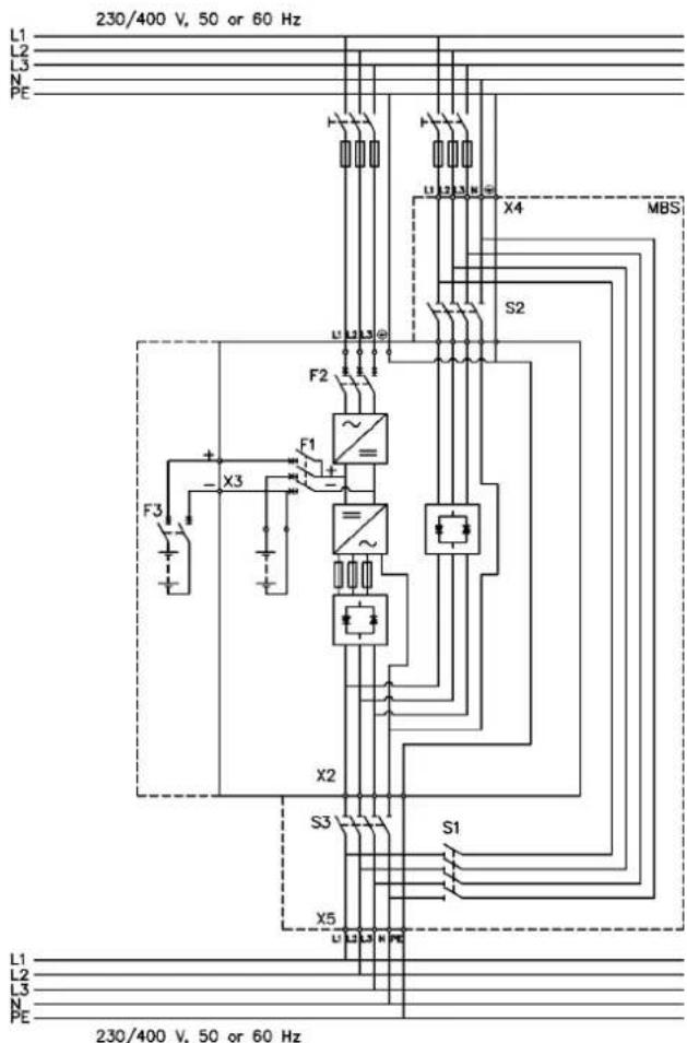
Figure 15. Wiring diagram of UPS N-model with integral MBS.
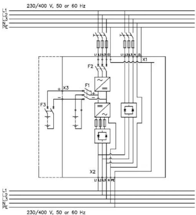
Figure 16. Wiring diagram of UPS N-model.
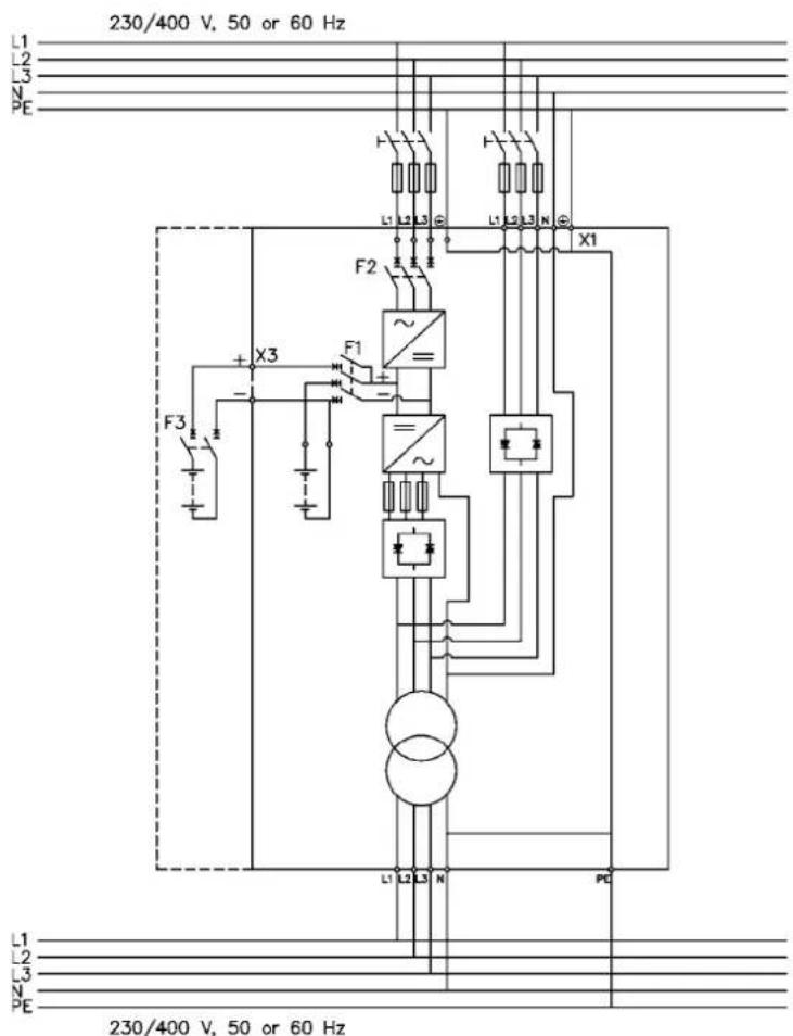
Figure 17. Wiring diagram of UPS NT-model
External Battery Cabinet (EBC) installation procedure
The installation procedure is as follows:
- The EBC is recommended to place next to the UPS unit.

Note!
Do not place EBC on the UPS unit.
- The required minimum distance for UPS unit and EBC is ten millimetres, which is also required distance between two EBCs.
- Turn F1 battery breaker from the UPS unit in OFF position.
- Check that the circuit breaker F3 of the EBC is in the OFF position. To minimise safety risk disconnect one of the cable (+ or -) from battery string to break a battery circuit. Do not remove the safety wire of the circuit breaker before all the wires are connected and the installation of the whole system is ready. Remove plate A (See figure below.) on the rear side of the EBC to connect cables to EBC's terminal block X6. Bring cables outside from the EBC by removing the cover plate B. Place the plate A back to the original position and use cover plate B as a cable clamp.

Warning!
If an internal battery string is installed and already connected to the terminal block there is a danger of a lethal electric shock. Turn F1 battery breaker from the UPS unit to OFF position and measure the voltage across the terminals to be 0 (zero) before any operations with terminal X3.
- If the system consists two or more EBC connect first the EBCs parallel as follows:
a) Connect the cables to second EBC in the same way as guided in point four (4) of this installation procedure.
b) Remove the cover plate C of the first EBC and connect cables to terminal block X6. Use the cover plate C as a cable clamp. - When all the EBCs are connected parallel, make sure that F1 battery breaker is in OFF position before connecting cables to terminal block X3 of the UPS unit. Otherwise the terminal block X3 is live. To be on the safe side, measure the voltage across the terminals to be 0 (zero).
- After installation connect disconnected battery cables to strings, check that the removed plates on right positions, remove safety wires from circuit breakers and turn breakers of EBCs and the UPS to ON position.
- Finally change the Number of 32 pcs. battery strings from User Settings. SETTINGS -> USER SETTINGS -> NUMBER OF BATTERY STRINGS.
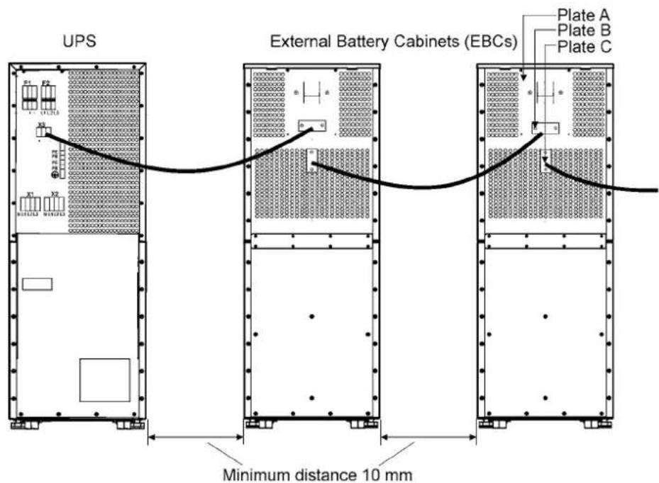
Figure 18. Connection of UPS and External Battery Cabinets
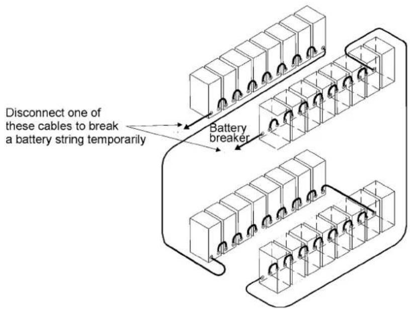
Figure 19. To minimise safety risk remove + or - cable from battery string before connecting UPS and EBCs.
6. Software and connectivity
The software Suite CD-ROM that is bundled with the UPS contains software distributions and documentation in CD format. Furthermore, the comprehensive connectivity option portfolio includes Web/SNMP adapters for networked environments, Modem card for 24/7 remote monitoring, ModBus/Jbus card for building management system integration, relay interface cards for industrial and facilities use and RS-232 cards for serial communication to one or multiple computers.
Communication cables
It is recommended that the control cables and power cables be installed on separate trays. Where control cables will cross power cables make sure they are arranged at an angle as near to 90 degrees as possible.
All control cables shall preferably be shielded. If the shield is grounded, this shall take place on only one end of the cable.
The procedure for connecting the control cables is the following:
- Remove the front cover by lifting the cover from the bottom outwards by releasing the re - taining clip. It's located in the bottom part of the bezel.
- Locate the control terminal or XSlot module where you want to install the communications cable.
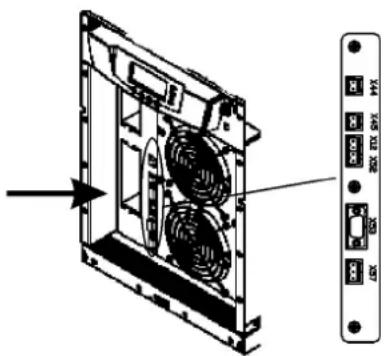
Figure 20. Location of control cable terminals: Signal inputs (X44 & X45); EPO (NC (X12) & NO (X52)); RS-232 (X53); Relay output (X57).
Connection to the standard RS-232 port (X53)
The standard RS-232 interface uses 9-pin female D-sub connector. It shall be used with the delivered cable for a computer or external modem connection. The data is transmitted with XCP protocol that includes status and meters information about the UPS. The RS-232 port has the following format:
- Communication speed 19200 bps*
- Data bits 8
- Parity None
- Stop bits 1
- Handshake None
* Communication speed can be changed via LCD menu
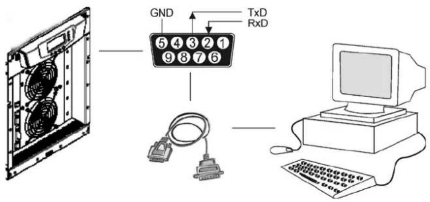
Figure 21. Identification of the interface port pins.
LanSafe software
The LanSafe software shuts down computers and whole networks in case of an extended power failure. It provides basic monitoring, data logging, notification and event actions for a single UPS solution. The software is bundled free of charge in Software Suite CD.
The connection procedure for the RS-232 interface port is following:
- Connect the RS-232 communication cable to the computer.
- Connect the RS-232 communication cable to the serial interface on the UPS.
- Run the UPS software installation disk (Software Suite CD) on the computer.

Note!
If communication does not work choose the correct baud rate from the LCD menu Please refer to the optional software manuals for appropriate bit rate settings.
External control connections
The UPS has an input/output interface for direct communication with your computer system. It is located behind the front bezel of the UPS unit. The cables connected to these terminals should be connected to cable clips.
Input and output terminals have a functional isolation from terminal to terminal. They are connected to the chassis through individual 1 MΩ resistors.
| X44 | ||
| 2 | - polarity | Signal input 1 (Programmable) |
| 1 | + polarity | |
| X45 | ||
| 2 | - polarity | Signal input 2 (Programmable) |
| 1 | + polarity | |
| X12 | ||
| 2 | - polarity | Emergency Power Off (Normally Open) |
| 1 | + polarity | |
| X52 | ||
| 2 | - polarity | Emergency Power Off (Normally Closed) |
| 1 | + polarity | |
| X57 | ||
| 3 | RO1 common point | Relay Output |
| 2 | RO1 normally closed | |
| 1 | RO1 normally open | |
Figure 22. External control cable connections to the UPS.

Note!
Pay attention to proper polarity if one is using a semiconductor switch type. A relay or other mechanical control is a preferred method.
Emergency Power Off (EPO)
This input is used to shut down the UPS from a distance. This feature can be used for emergency power down. There are two modes of operation, normally closed at X52 and normally open at X12. Remote shut down terminal X52 pins 1 and 2 are as factory default linked (X12 is open). When the loop on X52 is opened, the logic circuitry will immediately shut down the UPS output and open the battery breaker (F1).

Note!
EPO does not necessarily disconnect supply to load when unit is on internal or external bypass. Guaranteed disconnection of bypass supply has to be through a separate disconnect switch located in the supplying switchgear cabinet.
In order to have the UPS running again pins 1 and 2 of connector X52 have to be reconnected and the UPS started manually. The pins must be shorted in order to keep the UPS running. Maximum resistance is 10 ohm. The EPO shall not be galvanically connected to any mains connected circuits. Reinforced insulation to the mains is required. See also "Start-up after EPO".
If the use of normally open EPO operation is desired, the loop on X52 has to be retained and the normally open EPO switch connected to X12. Operation is as above.
Relay outputs
The UPS incorporates a programmable relay output with potential free contacts at X57 for remote alarm indications. It is rated for max. 30 VAC 1 A or 60 VDC 0,2 A nominal values. Additional (4) relay outputs can be obtained with the XSlot compatible AS/400 Relay Module (optional). For more information see the section "Using relay outputs"

Warning!
The relay contacts must not be directly connected to mains related circuits. Reinforced insulation to the mains is required.
Programmable signal inputs
The UPS incorporates two programmable inputs (X44, X45). Use of a non-polar (relay) control input is recommended. The pins must be shorted with maximum resistance of 10 ohm in order to activate the specific input.

Note!
Please note the polarity of the inputs as indicated in the external control connections if used with a polarity control.
The default and programmable settings for the signal inputs are
a) Disable Bypass Operation
If active the automatic transfer to the static bypass is prevented.
b) Charger off
If active the batteries charging is disabled. In case of mains power outage the discharge of batteries is supported.
c) Remote ON/OFF
If active the UPS output turns off regardless of mode of operation. Auxiliary power, fan, communications and rectifier/battery charger shall remain functional. Restart initiated immediately when inactive.
d) Request Bypass
If active the UPS transfers to bypass if bypass voltage, frequency and synchronisation are ok.
e) Request Normal
If active the UPS transfers to inverter operation if not prohibited by EPO or alarm condition.
f) Force Bypass
If active the UPS is forced to static bypass operation regardless of the bypass status.
g) External Battery Breaker Status
If active the UPS knows that the batteries are disconnected.
h) Building alarm 1-6
These can be activated separately or at the same time with other building alarms.
i) Not in use (default)
j) Shutdown
If active the UPS will shutdown immediately.
k) Delayed Shutdown
If active the UPS will shutdown after user configurable delay time. Restart initiated immediately when inactive.
1) Normal/Bypass
If active the UPS transfers to bypass if ok. If inactive the UPS transfers to inverter when possible.
m) Output transformer over temperature
If active the UPS output turns off after user configurable delay time.
n) Input transformer over temperature without bypass
If active the UPS will start to operate on battery or shutdown when batteries not available after one minute delay.
o) Input transformer over temperature with bypass
If active the UPS will start to operate on battery or transfer to bypass after one minute delay.
XSlot communication (option)
XSlot modules allow the UPS to communicate in a variety of networking environments and with different types of devices. The UPS incorporates two (2) empty XSlot communication bays.
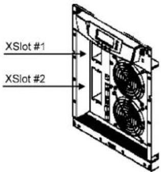
Figure 23. Location of empty XSlot bays.
The UPS supports two serial communication devices according to the table below.
| Independent Multiplexed | |||
| Configuration XSlot #1 X-slot #2 Std. RS-232 port | |||
| Default #1 Any XSlot Module | Any XSlot Module Not in use | ||
| Default #2 Any XSlot Module | Relay Module Available | ||
| Default #3 Any XSlot Module | Not in use Available | ||
Table 24. Typical XSlot configurations for UPS communication.
Web/SNMP Module (optional)
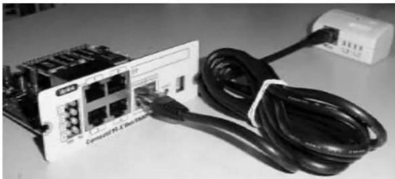
The module supports SNMP and HTTP compliant remote monitoring and shutdown for the protected computer systems. It can be connected to a twisted-pair Ethernet network (10/100BaseT) using an RJ45 connector.
The Web/SNMP module has a build-in switching hub that allows three (3) additional network devices to be connected to the network without the requirement of additional network drops. In addition, an Environmental Monitoring Probe can be requested from the UPS manufacturer to obtain humidity, temperature, smoke alarm and security information. It is connected to the communication port of the Web/SNMP module as option.
natural_image
Black-and-white photo of a network switch connected to a computer terminal with a cable (no visible text or symbols)Figure 25. ConnectUPS-X Web/SNMP Module and Environmental Monitoring Probe.
AS400 Relay Module (optional)
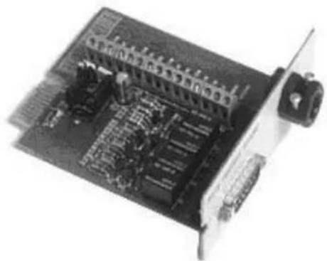
The Relay Module provides potential free relay interface for AS/400 connected computers and industrial applications. The relay interface supports both 15-pin D-sub connector and terminal block connections up to four (4) potential free relays.
The relay contacts are rated for 1 A, 30 Vac or 200 mA, 60 Vdc, and they have a galvanic isolation from the other circuits of the UPS unit.
natural_image
Close-up of an electronic circuit board with visible components and connectors (no text or symbols)Figure 26. AS400 Relay Module.
Single Serial Port Module (optional)
To establish communication between the UPS and a computer, connect your computer to the UPS communication port using the supplied communication cable.
When the communication cable is installed, power management software can exchange data with the UPS. The software polls the UPS for detailed information on the status of the power environment. If a power emergency occurs, the software initiates the saving of all data and an orderly shutdown of the equipment.
Modus/Jbus Module (optional)
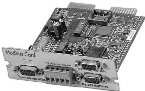
The Modbus module provides monitoring and integration to the Building Management Software (BMS) such as Wonderware. It features continuous and reliable communication through isolated DB9 ports (RS485/RS232) or a terminal strip (RS485).
natural_image
Close-up of a Modbus Card module with visible circuitry and connectors (no readable text or symbols beyond labels)Figure 27. Modus/Jbus Module.
7. User operations
The UPS has a four-button graphical LCD with backlight. It provides useful information about the unit itself, load status, events, measurements, and settings.
The LCD backlight is switched on by pressing any button. It has a timeout that automatically switches off after 15 minutes of inactivity.
Display functions
As default and after 15 minutes of inactivity the UPS is showing the selectable start screen:
-
Logo screen
-
Mimic screen (See User Settings on LCD screen)
The screen backlit has automatic shutdown after long period of inactivity. It will light up once a button is pushed. The right side button will initiate the text to the screen. The scrolling through the menu structure is done with buttons indicated by the ↑ ↓ images of the LCD screen. The menu structure is shown in the table below. There are small differences in the menu structure between single and parallel mode.
| Parallel Mode | Single Mode | Main Menu Submenu Functions | ||
| I | ||||
| xx UPS STATUS -> | UPS off / System normal / UPS supporting load / UPS on battery/ UPS on bypass / +active alarms and notices / +battery status(resting, charging, floating, not connected, discharging) | |||
| I | ||||
| xx EVENT LOG -> Notice / Alarm | ||||
| I | ||||
| xx | MEASUREMENTS | PARALLEL SYSTEM | Parallel unit 1...4 kW/Parallel total kW | |
| OUTPUT | Voltage / Current / Frequency / Power | |||
| BATTERY | Voltage / Current / Runtime | |||
| INPUT | Voltage / Current / Frequency | |||
| BYPASS | Voltage / Frequency | |||
| I | ||||
| x | x | CONTROL | -> | Goto bypass / Battery test / Display test / Reset error state |
| I | ||||
| xx | SETTINGS | USER SETTINGS | Date / LCD contrast / Change language / Relay config / Signalinputs / Serial port config / Parallel operation settings / Startscreen / User password / Audible alarms / Battery chargingmethod / +list of std. settings | |
| SERVICE SET-TINGS | Adjust parameters / Adjust events / Reset custom / Clear history/+ modem call settings | |||
| I | ||||
| x | x | IDENTIFICATION | -> | UPS Type / Part nro. / Serial nro / Revisions |
| I | ||||
| x | TURN UPS ON | -> | - | |
| I | ||||
| x | TURN UPS OFF | |||
| I | ||||
| x | TURN SYSTEM ON | |||
| I | ||||
| x | TURN UPS OFF | |||
| I | ||||
| x | TURN SYSTEM OFF | |||
Table 28. Menu map for display functions.
User Settings
The UPS has the following typical settings that are user configurable. Note that some of the settings become effective at the next start-up of the UPS. User settings can be configured via LCD menu. Select SETTINGS → USER SETTINGS
| Description Available settings Default setting | ||
| General: | ||
| Display contrast adjustment + / - Moderate | ||
| Display language [English], [Spanish], [French], | [German] English (British) | |
| Date & time [xxxx-xx-xx] 0001-01-01 | ||
| Audible alarms [Normal], [Disabled] Normal | ||
| Normal screen in display [logo], [mimic] Product name | ||
| User settings password [Not required], [Set] | Not required | |
| Nominal values: | ||
| Nominal output voltage (L-N) | [220], [230], [240] | 230 Volts |
| Nominal output frequency | [50 Hz], [60 Hz] | 50 Hz |
| Rectifier phase current limit | Step: 1 A | 32 A |
| Communication and connectivity: | ||
| Disable control commands | [Enabled], [Disabled] | Disabled |
| Communication speed | [1200], [2400], [9600], [19200] | 19200 bps. |
| Std. relay output function | [UPS ON/OK], [Custom], [Battery low], [System on bypass], [System on battery] | UPS ON/OK |
| Signal input #1-2 function | [Empty], [see Signal inputs] | Empty |
| Hardware remote off delay for hardware Remote off with restart function. | Step: 1 sec. | 120 sec |
| XSlot relay output 1-4 function | [Nothing], [see Signal inputs] | XSlot defaults: #1: on battery #2: battery low #3: UPS on/ok #4: on bypass |
| XSlot input signal (long break via Rx) | Nothing | |
| XSlot shutdown signal activation delay before the signal is accepted. | Step: 1 sec. | 5 sec |
| Bypass and synchronisation: | ||
| Usage of bypass | [Enabled], [Disabled] | Enabled |
| Require synch at transfer on bypass | [Required], [Not Required] Not required | |
| Transfer on bypass on overload | [Immediately], [after delay] | Immediately |
| Synchronization enable | [Enabled], [Disabled] | Enabled |
| Bypass voltage deviation high limit | +1% ... +20%, step: 1% | +10% |
| Bypass voltage deviation low limit | -1% ... -20%, step: 1% | -15% |
| Synchronization window | 0.5 ... 3.0 Hz, step: 0.1 Hz | ±2.0 Hz |
| Frequency slew rate (not in parallel mode) | 0.1 ... 3.0 Hz/s, step 0.1 Hz/s | 0.2 Hz/s |
| Battery information and settings: | ||
| ABM charging cycling disable [Enabled], [Disabled] Enabled | ||
| Charging temp compensation [Enabled], [Disabled] Enabled | ||
| Battery size setting Step: 1 Watts/cell 24 Watts/cell | ||
| Number of 32 pcs. battery strings 0 (no batteries), 1, 2, 3, 4... 1 string | ||
| Battery low alarm level Step: 0.01 V/cell 1.88 V/cell | ||
| Automatic battery support test [Enabled], [Disabled] Enabled | ||
| Maximum charging current Step: 0.1 A [max. 20 Amps] 3 A | ||
| Output on, automatic delay time before turning the output on | [Disabled], [Set delay, step: 1 sec] | 0 sec. |
| Output off, automatic delay time on battery after which output is turned off | [Disabled], [Set delay, step: 1 sec] | Disabled |
| User preferences: | ||
| Operation priority while rectifier input break | [On battery], [On bypass] | On battery |
| Site wiring fault w/ wrong Neutral connection | [Enabled], [Disabled] Enabled | |
| Power Strategy | [Standard], [High Efficiency] | Standard |
| Parallel settings: | ||
| Parallel unit number | [Single unit], [Unit #1], [Unit #2], [Unit #3], [Unit #4] | Single unit |
| Parallel operation mode | [Redundant mode], [Capacity mode] | Redundant mode |
| Synchronization | [Enabled], [Disabled] Enabled | |
| Start auto calibration | ||
| Parallel XCP | [System], [Unit] | System |
| Minimum units to support load | [0], [1], [2], [3], [4] | 2 |
Table 29. User setting in the LCD menu screen.
Configuring user settings
User settings can be configured via front panel. Select Settings from main menu and then select User Settings.
Changing language
Pressing and holding down the first button on the left for about 3 seconds selects the language menu. This action is possible from any LCD menu screen.
The default firmware has four main languages: English, Spanish, French and German. Other local language packages including Chinese, Greek and Russian can be requested from the local service representative.
Changing charging current
Maximum charging current setting should be checked when needed back-up time needs more than 3 Amps charging current.
| Load (kVA)p.f. 0.7 | Back-up time Min | current | Load (kVA)p.f. 0.7 | Back-up time Min | current | |
| 10 1 h 1.8 A 15 1 h | 2.5 A | |||||
| 10 3 h 4 A 15 3 h 6 | 5 A | |||||
| 10 5 h 6.5 A 15 5 h | 9 A | |||||
| 10 10 h 13 A 15 10 | h 18 A |
Table 30. Required battery charge currents.
Select Maximum charging current from User Settings menu. Default setting is 3.0 Amps and it is changeable up to 20 Amps. Minimum step is 0.1 A.

Note!
Maximum charging current is dependent on output load and power rate of the UPS. If the UPS is supporting maximum output load the highest level of Maximum charging current is 3.0 A, which is also the default setting. As a thumb rule, 1 kW decrease in the load provides extra 2.0 A charging capacity. For example, the charging capacity is 5 Amps at 8 kW load, and 7 A at 7 kW load.
Using relay outputs
Relay outputs can be used for remote alarm indications.
Each relay has four standard pre-programmed settings for alarms:
• on bypass, UPS ok, battery low, on battery
One of the standard relay settings is "custom" that can be customised by the user.
The procedure to select customised alarms:
- Push any key of the control panel to enable the functions on the LCD screen.
- First select "SETTINGS", then "USER SETTINGS" and finally "RELAY CONFIG" from the LCD menu.
- Select the relay what is needed to be configured (ALARM-1 is fixed relay output X57).
- Select "empty" to clear old settings.
- Select "custom" and activate needed alarms with the button on the right.
- After the selection press "OK" button
- Finally test that UPS alarms correctly
Normal start-up
Check the mechanical and electrical installation of the UPS before start-up. Go through the checklist below together with another person.
Check
☐ Read the attached safety manual before you work on the unit.
☐ The unit is fixed according to mechanical installation
☐ The ambient conditions are within specification.
☐ The cooling air will flow freely.
☐ The UPS is grounded properly.
☐ The input and bypass voltages match the UPS nominal voltage.
☐ The input, bypass, battery and output terminal connections are OK.
☐ Appropriate input and bypass fuses and disconnectors are installed.
□ Appropriate backfeed warning sign for disconnectors are installed.
☐ Appropriate cables sizes are used.
☐ The external control connections inside the UPS are OK.
☐ There are no tools, foreign objects or dust inside the UPS from the installation.
□ Covers are in place.
☐ Optional MBS is placed to UPS position as default.
You are then ready to proceed with the starting up the UPS:
- Turn the battery and input circuit breakers to ON position.
- UPS will enter a stand-by mode and starts to charge batteries with a cooling fan operation -al. Output is without the voltage in the stand-by mode.
- Push any key of the control panel to enable the functions of the LCD screen
- Select "TURN UPS ON" from the LCD menu (see: Display Functions)
- Press and hold ← button for 2 sec. There shall be no sound during the hold.
The UPS shall check its internal functions, synchronise to bypass and start to supply the load. The green LED is blinking if there occurs an active notice. In normal operation the green LED is constantly lit if no new active notice such as 'unsynchronised' or similar notices present.
The output voltage shall be verified from the output measurements screen of the LCD. If there is voltage in the output then UPS is supplying the load.
Battery start-up
UPS will start on battery if mains is not available. Note that the UPS behavior may be slightly different from the normal start-ups.
Start-up after EPO
- Find out the reason that caused EPO
- Check that there are no risk to start the UPS again
- Follow Normal start-up check list and procedure
Shutdown
The procedure to shutdown from LCD is following:
- Push any key of the control panel to enable the functions of the LCD screen
- Select "TURN UPS OFF" from the LCD menu (see: Display Functions)
- Press and hold ↓ button for 5 sec. There shall be an indication sound during the hold.
- UPS shall do a shutdown routine.
- Turn the battery and input circuit breakers to OFF position to finalise the shutdown procedure.

Note!
The behaviour is different if UPS is turned off from the programmable input or through communication cards. If battery and input circuit breakers are left ON, UPS will enter a stand-by mode and starts to charge batteries with a cooling fan operational. Output is without the voltage in the stand-by mode.
8. Maintenance
All operations inside the unit must be performed only by a service engineer from the manufacturer or from an agent, authorised by the manufacturer.
The troubleshooting procedure gives simple remedial if a malfunction occurs in the UPS. The operator should start the trouble shooting if there is an active alarm indicated on the LCD screen. Service should be contacted if the active alarm is abnormal and displayed as a service code.
Call service if you are not able to solve the problem.
| LCD display Description Action | ||
| Overload | The connected load needs more power than the UPS is rated to provide. The inverter or static bypass is supplying the excessive load level. | Shut down the least important load that is connected to the UPS. The UPS should switch back to normal operation once the load level is acceptable. |
| Battery test failed Your | batteries are detected to be faulty. | Batteries should be replaced and you need to contact the local office or representative of the UPS manufacturer. |
| Battery low | The UPS is operating in stored energy mode. It will shut down soon due to low battery voltage. | Make controlled shutdown of the protected load immediately to prevent loss of data. |
| On battery | The UPS is operating in stored energy mode. | Save your data and perform a controlled shutdown of your server load. |
| Overtemperature High | UPS temperature is detected. | Check that fans are operational and ventilation holes are not blocked. Make sure the ambient temperature is not excessive |
Table 31. Typical alarms displayed in the LCD screen of the UPS unit.
Regular service/intervals
The UPS requires very little maintenance if installed in an appropriate environment. In order to ensure maximum availability of the UPS, manufacturer recommends signing a proactive service agreement with a local authorised service provider.
| Maintentenance Interval | |
| Batteries change ~ 3-5 years / service | |
| Batteries test ~ 18 months / service | |
| Cooling fan change ~ 5 years / service |
Table 32. Routine maintenance intervals recommended by the manufacturer.
Batteries
The condition of the batteries is crucial for operation. The UPS will indicate by audible and visual alarms if the capacity of the battery bank has decreased. The UPS units are provided with the automatic battery test and ABM management function to continuously monitor the condition of the battery bank.
Servicing of batteries should be performed or supervised by personnel knowledgeable about batteries and required precautions. When replacing batteries, replace with the same type and number of batteries.

Note!
Do not dispose of batteries in a fire. The batteries may explode.
Do not open or mutilate batteries. Released electrolyte is harmful to the skin and eyes. It may be toxic.
CAUTION RISK OF EXPLOSION IF BATTERY IS REPLACED BY AN INCORRECTED TYPE. DISPOSE OF USED BATTERIES ACCORDING TO THE INSTRUCTIONS
Cooling fan
The cooling fan lifespan of the UPS unit is about 60 000 operating hours. The actual lifespan depends on the environment and ambient temperature.
Fan failure can be predicted by increasing noise from the fan bearings. The fan replacement is recommended once this symptom starts appearing.
Do not use other than manufacturer's specified spare parts.
LED Indicators
The UPS unit has (4) LEDs to indicate the status.
| Graphical sign LED Description Note | |||
 | Green UPS status is ok. Blinking when a new notice message is active. | ||
 | Yellow 1 UPS is in battery mode. | ||
 | Yellow 2 UPS is in bypass mode. | ||
 | Red UPS has an active alarm. Blinking when new alarm is not reset and still active. | ||
Table 33. Description of the LED indicators.
Maintenance bypass switch (MBS) operation
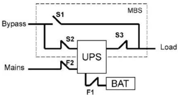
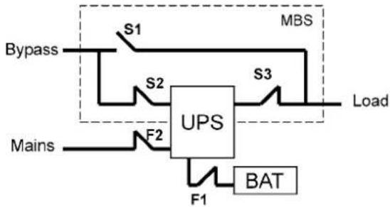
The maintenance bypass switch may be as standard or as optional in your system depending on the ordered configuration. The operation of the MBS is allowed for a trained person only who is familiar with the UPS behaviour and functions. The full UPS wiring diagram with a MBS switch is presented in the installation part of the manual.

Note!
The MBS consist of three switches and failure to understand the correct sequence may drop the critical load.
flowchart
graph TD
    A["Bypass"] --> B["S1"]
    B --> C["UPS"]
    D["Mains"] --> E["F2"]
    E --> F["F1"]
    F --> G["BAT"]
    H["Load"] --> I["S3"]
    I --> J["MBS"]
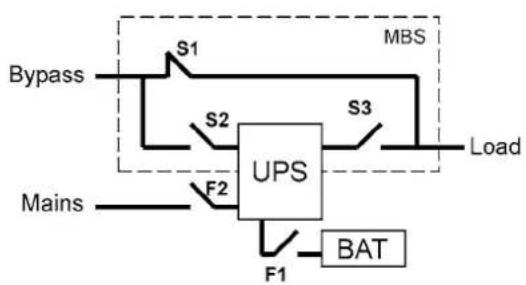
Figure 34. The normal positions of the three MBS switches.
Turn UPS from normal mode to mechanical bypass
The procedure to turn the UPS to mechanical bypass switch is described below.
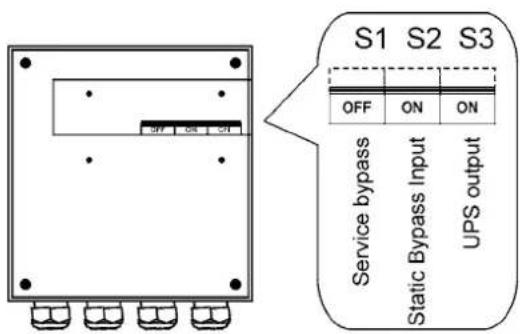
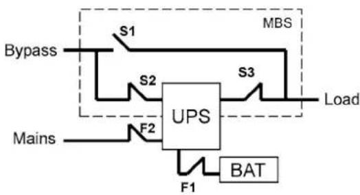
flowchart
graph TD
    A["Bypass"] --> B["S1"]
    B --> C["UPS"]
    C --> D["MBS"]
    D --> E["S3"]
    E --> F["Load"]
    G["Mains"] --> H["F2"]
    H --> I["F1"]
    I --> J["BAT"]
    J --> K["F1"]
    K --> L["F2"]
    L --> C
Figure 35. The normal (UPS supplying the load) positions of the three MBS switches.
No break transfer from normal mode to Service Bypass:
- The normal start position should be following:
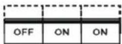
-
Use LCD to turn the UPS on internal static bypass mode. Remember to verify the transfer before proceeding the next step.
-
Remove the locking plate of the S1-3 switches.
-
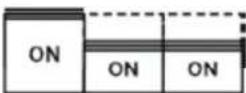
Turn ON the S1 switch to bypass UPS:
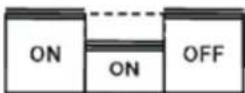
- Turn OFF the S3 switch to disconnect UPS output:
-
Use LCD to turn UPS OFF.
-
Turn F1 battery breakers and F2 input to OFF position.
-
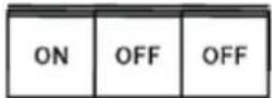
Turn OFF the S2 switch to disconnect UPS bypass input:
- Remount the locking plate of the S1-3 switches to the position to prevent the use of them.
- UPS is now in the mechanical bypass mode, see below:
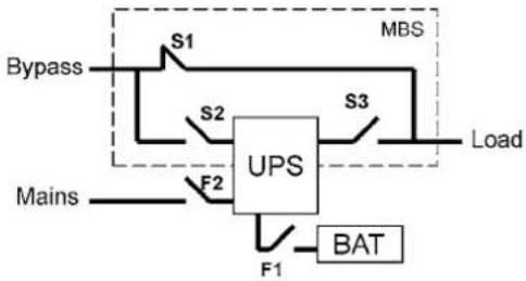
flowchart
graph TD
    A["Bypass"] --> B["S1"]
    B --> C["UPS"]
    C --> D["S2"]
    D --> E["MBS"]
    E --> F["S3"]
    F --> G["Load"]
    H["Mains"] --> I["F2"]
    I --> J["F1"]
    J --> K["BAT"]
Turn UPS from mechanical bypass to normal mode
The procedure to turn the UPS back to normal mode is described below.
flowchart
graph TD
    A["Bypass"] --> B["S1"]
    B --> C["UPS"]
    C --> D["MBS"]
    C --> E["S3"]
    E --> F["Load"]
    G["Mains"] --> H["F2"]
    H --> I["F1"]
    I --> J["BAT"]
Figure 36. The service (bypass supplying the load) positions of the three MBS switches.
No break transfer from Mechanical Bypass to normal mode:
- The normal start position should be following:
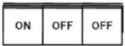
- Remove the locking plate of the S1-3 switches.
- Turn ON S2 switch to connect bypass input to UPS:
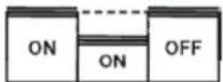
- Turn the F1 battery and F2 input breakers to ON position.
- Use LCD to "Turn UPS on" and wait until fully started.
- Make sure the UPS is not displaying alarms or notices alarm with the green LED lit.
- You may verify the output voltage from the meters screen of the LCD.
-
Use LCD to transfer the UPS to internal static bypass. Remember to verify the transfer before proceeding the next step.
-
Turn ON S3 switch to connect UPS output to load:
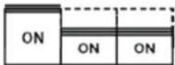
- Turn OFF S1 switch to disconnect bypass output:
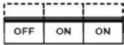
-
Use LCD to transfer the UPS to normal mode.
-
Remount the locking plate of the S1-3 switches to the position to prevent the use of them.
-
UPS is now in Normal mode, see below:
flowchart
graph TD
    A["Bypass"] --> B["S1"]
    B --> C["UPS"]
    C --> D["S3"]
    D --> E["Load"]
    F["Mains"] --> G["F2"]
    G --> C
    H["F1"] --> I["BAT"]
    I --> C
    style A fill:#f9f,stroke:#333
    style E fill:#ccf,stroke:#333
    style C fill:#cff,stroke:#333
    style D fill:#ffc,stroke:#333
    style F fill:#cfc,stroke:#333
    style G fill:#fcc,stroke:#333
    style H fill:#fcc,stroke:#333
    style I fill:#fcc,stroke:#333
9. Parallel systems
Overview
Parallel UPS configurations are recognised as either redundancy or capacity systems. The redundancy system is used to improve the system reliability with N+1 redundant UPS module. The capacity system for its part provides the maximum output power without focusing to the highest system reliability.
A parameter selection is used to switch between the redundancy and capacity modes. It is important to remember that the mode is affecting to the output power rating and overall system reliability.
UPS modules of the parallel system share equally the load with Hot Sync® technology. The parallel outputs can be combined in a System Parallel Module or cabinet. It is the system component containing the obligatory service switches. Customer's low-voltage distribution panel can also be used instead of the System Parallel Module. In the redundancy system, service switches enable the maintenance or service on an UPS module. In the capacity system, one needs to have a common system bypass switch to do the maintenance or service without safety hazards.
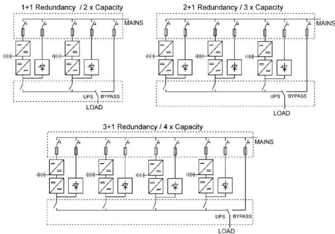
Figure 37. Parallel configurations with UPS modules
Field upgrading can be used to extend existing capacity/redundancy systems with UPS modules. The upgrading must be carried out by service personnel from the manufacturer or from an agent authorised by the manufacturer.
Tie cabinets
The Tie Cabinets (TCs), provided by UPS manufacturer, has input connections up to three parallel UPS modules. It is also possible to use two redundant UPS modules and one bypass connection. This bypass option can be used for service or test purposes.

Note!
It is not allowed to feed the load simultaneously from mains (bypass) and inverter(s) of the UPS unit(s). While turning the switch, where the bypass is connected, ON/OFF, UPS should be on static bypass mode or shut down.

Note!
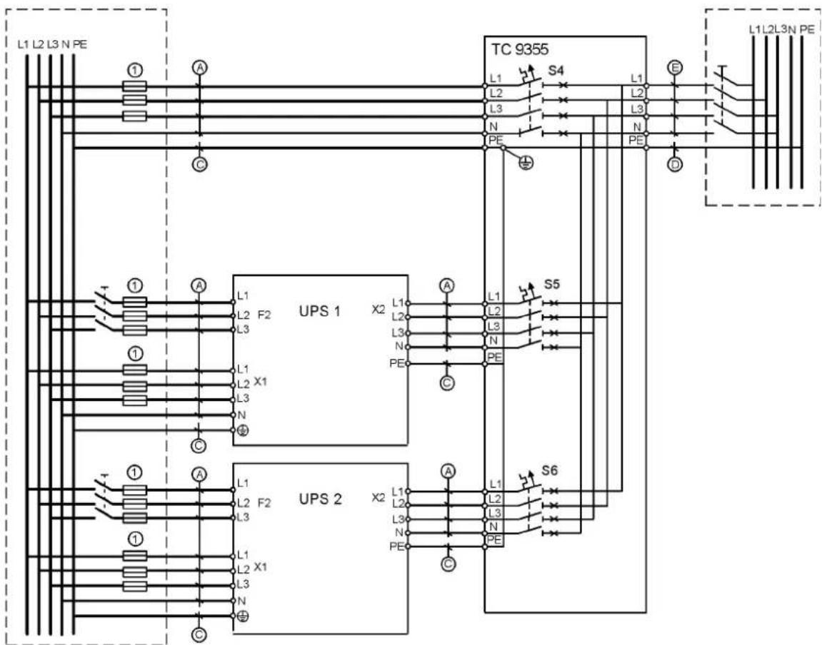
The maximum load supported by the system is limited to 15 kVA if there are two UPSs and bypass connected to TC (See wiring diagrams below).
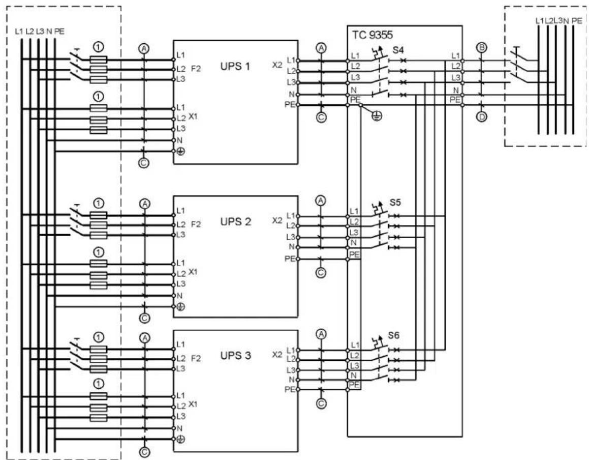
Terminals of the TC have four-wire connection (L1, L2, L3 and N) and ground terminals. The upper ground terminal is for a load cable and the lower ground terminal is for UPSs. The wiring shall be done according to the wiring diagrams. The terminals and cable routing is shown in Figure 39.
Weight 10 kg
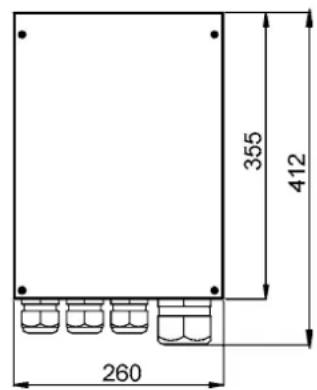
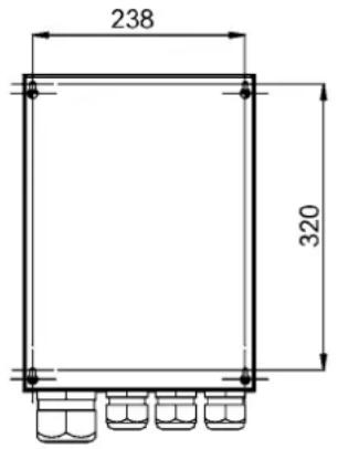
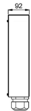
Figure 38. Dimensions of the Tie Cabinet
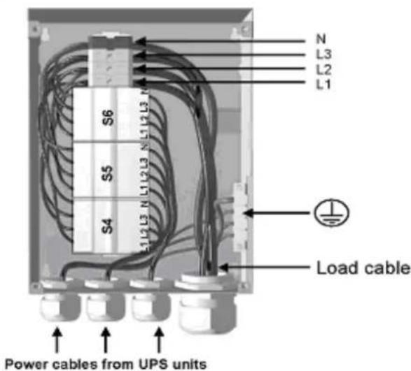
Figure 39 Cable routing of Tie Cabinet
flowchart
graph TD
    subgraph UPS_1_UPS_1_UPS_1_UPS_1_UPS_1_UPS_1_UPS_1_UPS_1_UPS_1_UPS_1_UPS_1_UPS_1_UPS_1_UPS_1_UPS_1_UPS_1_UPS_1_UPS_1_UPS_1_UPS_1_UPS_1_UPS_1_UPS_1_UPS_1_UPS_1_UPS_1_UPC
        L1 --> L2 --> L3 --> N --> PE --> S4 --> L1 --> L2 --> L3 --> N --> PE --> D --> L1L2L3N
        L2 --> L3 --> L3 --> N --> PE --> S4 --> L1L2L3N
        L3 --> L3 --> L3 --> N --> PE --> S4 --> L1L2L3N
        N --> PE --> S4 --> L1L2L3N
        PE --> S4 --> L1L2L3N
        S4 --> L1L2L3N
    end
    subgraph UPS_2_UPS_2_UPS_2_UPS_2_UPS_2_UPS_2_UPS_2_UPS_2_UPS_2_UPS_2_UPS_2_UPS_2_UPS_2_UPS_2_UPS_2_UPS_2_UPS_2_UPS_2_UPS_2_UPS_2_UPS_2_UPS_2_UPS_2_UPS_2_UPS_2_UPS_2_UPC
        L1 --> L2 --> L3 --> N --> PE --> S5 --> L1L2L3N
        L2 --> L3 --> L3 --> N --> PE --> S5 --> L1L2L3N
        L3 --> L3 --> L3 --> N --> PE --> S6 --> L1L2L3N
        N --> PE --> S6 --> L1L2L3N
        PE --> S6 --> L1L2L3N
        S6 --> L1L2L3N
        S6 --> L1L2L3N
        S6 --> L1L2L3N
        S6 --> L1L2L3N
        S6 --> L1L2L3N
        S6 --> L1L2L3N
        S6 --> L1L2L3N
        S6 --> L1L2L3N
        S6 --> S6
    end
Figure 40. Tie Cabinet's wiring diagram with three UPSs.
flowchart
graph TD
    subgraph UPS 1
        A1["①"] --> L1["L1"]
        A2["②"] --> L2["L2"]
        A3["③"] --> L3["L3"]
        A4["④"] --> L1L2L3NPE["⑤"]
    end
    subgraph UPS 2
        A5["①"] --> L1L2L3NPE["⑥"]
        A6["②"] --> L2L3NPE["⑦"]
        A7["③"] --> L3L3NPE["⑧"]
        A8["④"] --> L1L2L3NPE["⑨"]
    end
    L1 --> UPS 1
    L2 --> UPS 1
    L3 --> UPS 1
    L1L2L3NPE --> UPS 2
    UPS 1 --> X2["X2"]
    UPS 2 --> X2
    X2 --> PE["PE"]
    X2 --> N["N"]
    X2 --> L3L3NPE["⑨"]
    X2 --> L1L2L3NPE["⑩"]
    X2 --> PE["PE"]
    X2 --> S4["S4"]
    X2 --> S5["S5"]
    X2 --> S6["S6"]
    X2 --> PE["PE"]
    X2 --> PE["PE"]
    X2 --> PE["PE"]
    X2 --> PE["PE"]
    X2 --> PE["PE"]
    X2 --> PE["PE"]
    X2 --> PE["PE"]
    X2 --> PE["PE"]
    X2 --> PE["PE"]
    X2 --> PE["PE"]
    X2 --> PE["PE"]
    X2 --> PE["PE"]
    X2 --> PE["PE"]
    X1L2L3NPE --> TC9355
    TC9355 --> L1L2L3NPE
    TC9355 --> L1L2L3NPE
    TC9355 --> L1L2L3NPE
    TC9355 --> L1L2L3NPE
    TC9355 --> L1L2L3NPE
    TC9355 --> L1L2L3NPE
    TC9355 --> L1L2L3NPE
    TC1L2L3NPE --> L1L2L3NPE
    TC1L2L3NPE --> L1L2L3NPE
    TC1L2L3NPE --> L1L2L3NPE
    TC1L2L3NPE --> L1L2L3NPE
    TC1L2L3NPE --> L1L2L3NPE
    TC1L2L3NPE --> L1L1L3NPE
    TC1L2L3NPE --> L1L1L3NPE
    TC1L2L3NPE --> L1L1L3NPE
    TC1L2L3NPE --> L1L1L3NPE
    TC1L2L3NPE --> L1L1L3NPE
    TC1L2L3NPE --> L1L1L3NPE
Figure 41. Tie Cabinet's wiring diagram with two UPSs and bypass connected.
| UPS Module Cable A Cable C Fuse 1 | |||
| 8 kVA 2.5 mm | ^2 | 4 mm^2 | 16 A |
| 10 kVA 4 mm | ^2 | 4 mm^2 | 20 A |
| 12 kVA 6 mm | ^2 | 6 mm^2 | 25 A |
| 15 kVA 6 mm | ^2 | 6 mm^2 | 32 A |
| TC Module Cable B Cable D Cable E | |||
| 8 kVA 2.5 mm | ^2 | 4 mm^2 | 2.5 mm^2 |
| 10 kVA 4 mm | ^2 | 4 mm^2 | 4 mm^2 |
| 12 kVA 6 mm | ^2 | 6 mm^2 | 6 mm^2 |
| 15 kVA 6 mm | ^2 | 6 mm^2 | 6 mm^2 |
| 16 kVA 6 mm | ^2 | 6 mm^2 | (6 mm^2 )* |
| 20 kVA 10 mm | ^2 | 16 mm^2 | (10 mm^2 )* |
| 24 kVA 10 mm | ^2 | 16 mm^2 | (10 mm^2 )* |
| 30 kVA 16 mm | ^2 | 16 mm^2 | (16 mm^2 )* |
| 36 kVA 16 mm | ^2 | 16 mm^2 | - |
| 45 kVA 35 mm | ^2 | 16 mm^2 | - |
Table 42. Minimum cable and fuse ratings for the different parallel system with installation procedure C * (system bypass not allowed)

Note!
Protection fuses need to be used for load cabling if manufacturers Tie Cabinet (or similar) not used.
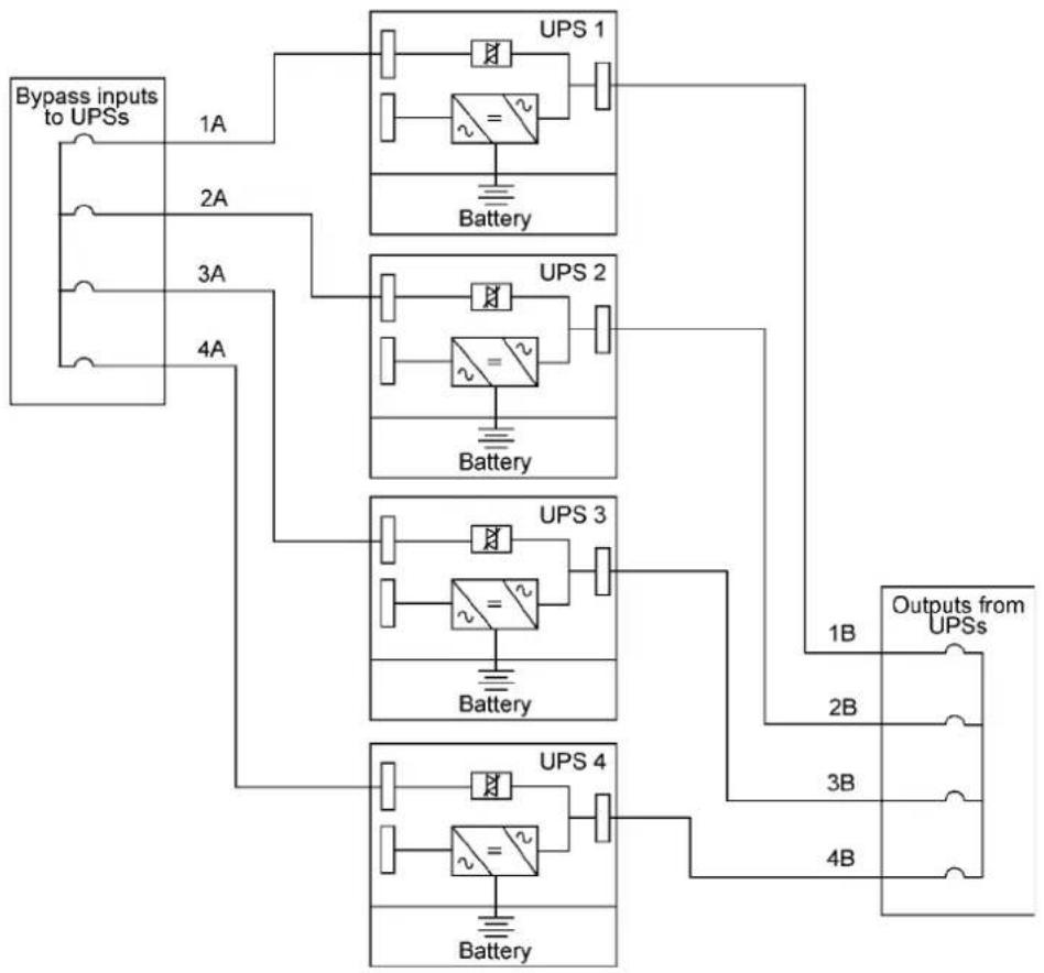
Required parallel system wiring length should be in accordance with the following rule, as referenced to the diagram below to ensure approximately equal current sharing when in static bypass mode (see Figure below:
Total length of 1A + 1B = Total length of 2A + 2B
= Total length of 3A + 3B
= Total length of 4A + 4B
This rule has a tolerance of approximately ± 10% for the combined input and output wire lengths. If installing only two UPS modules, this requirement is no longer required as each UPS is capable of supporting the full bypass requirement. However, this would preclude future expansion.
flowchart
graph TD
    A["Bypass inputs to UPSs"] --> B["1A"]
    A --> C["2A"]
    A --> D["3A"]
    A --> E["4A"]
    B --> F["UPS 1"]
    C --> G["UPS 2"]
    D --> H["UPS 3"]
    E --> I["UPS 4"]
    F --> J["Battery"]
    G --> K["Battery"]
    H --> L["Battery"]
    I --> M["Battery"]
    J --> N["1B Outputs from UPSs"]
    K --> O["2B"]
    L --> P["3B"]
    M --> Q["4B"]
Figure 43. Bypass wiring diagram and cable length notes.

Note!
Signal input cables need to be connected to all UPS when used.
XSlot Hot Sync card: installing and wiring
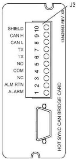
To enable parallel operation all the UPSs in the system need the XSlot Hot Sync card (see Figure below) installed into an open XSlot on the front of the UPS (see chapter XSlot communication from the UPS's User's Guide).
| Terminal J3 Name Description | ||
| 1 Alarm | Programmable UPS alarm. Activated by a remote dry contact closure | |
| 2 Alarm Rtn | ||
| 3 Alarm Relay NC | Normally-closed contact opens when UPS is on bypass. | |
| 4 Alarm Relay Com Bypass contact return. | ||
| 5 Alarm Relay NO | Normally-open contact closes when UPS is on bypass. | |
| 6 TX Remote Monitor Panel (RMP). Relay | ||
| 7 | TX | Interface Module (RIM, or Supervisory Contact Module (SCM) Connections. |
| 8 CAN L | Controller Area Network (CAN) Input for parallel operation. | |
| 9 CAN H | ||
| 10 Shield | ||
Figure 44. XSlot Hot Sync card and terminal interface
The Hot Sync communication wiring procedure should be done with shielded twisted pair (STP) as presented in the figure below. The maximum length of the cable is 40 m with shield connected to the terminal pin 10 from end of the both cables. Pay attention that you don't mix the polarity among the UPS modules.
| Communication Wiring Termination | |||
| From UPS 1 CAN card To UPS 2 CAN card | To UPS 3 CAN Card (If installed) | To UPS 4 CAN Card (If installed) | |
| J3-8 (L) J3-8 (L) J3-8 (L) J3-8 (L) | |||
| J3-9 (H) | J3-9 (H) | J3-9 (H) | J3-9 (H) |
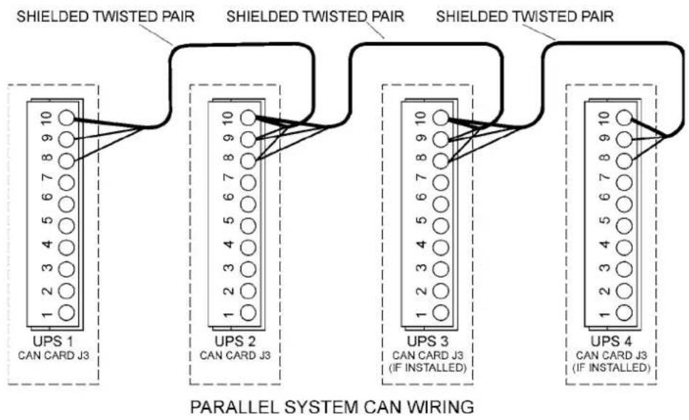
flowchart
graph TD
    A["UPS 1\nCAN CARD J3"] --> B["SHIELDED TWISTED PAIR"]
    B --> C["UPS 2\nCAN CARD J3"]
    C --> D["SHIELDED TWISTED PAIR"]
    D --> E["UPS 3\nCAN CARD J3\n(IF INSTALLED)"]
    E --> F["SHIELDED TWISTED PAIR"]
    F --> G["UPS 4\nCAN CARD J3\n(IF INSTALLED)"]
    style A fill:#f9f,stroke:#333
    style B fill:#ccf,stroke:#333
    style C fill:#cfc,stroke:#333
    style D fill:#fcc,stroke:#333
    style E fill:#cff,stroke:#333
    style F fill:#ffc,stroke:#333
    style G fill:#cfc,stroke:#333
Figure 45. Communication cabling wiring

Note!
XSlot Hot Sync card has built-in termination resistor enabled by a jumper J7. The default jumper setting without termination resistor is J7: Pin 2-3. The first and the last UPS modules should have the termination resistor enabled by connecting Pins 1 and 2 with the jumper J7.
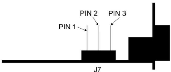
Figure 46. XSlot HotSync card and jumper settings: Resistor ON: PIN 1 and PIN 2 connected, No resistor: PIN 2 and PIN 3 connected (default setting)
Parallel operations
Start-up

Note!
Before start-up make sure that UPS installations have been carried out correctly and ground connections of both UPS units and parallel module have been connected. Check also that the XSlot Hot Sync cards are installed correctly and the communication line between UPSs is connected according to figure Communication cabling wiring.
When installation is completed correctly the start procedure can be started.

Note!
If some settings are changed from User settings the same changes need to be done separately to all of the UPSs in the system.
Carry out the following procedure to each UPS you want to have in system
- Turn the battery and input circuit breakers to ON position.
- UPS will enter a stand-by mode and starts to charge batteries with a cooling fan operation -al. Output is without the voltage in the stand-by mode.
- Push any key of the control panel to enable the functions of the LCD screen
- Select unit number in parallel system: Unit #1, Unit #2, Unit #3 or Unit #4. Select: SET-TINGS -> USER SETTINGS -> PARALLEL OPERATION SETTINGS -> PARALLEL UNIT NUMBER
- Select minimum units to support load: 0-4. Select: SETTINGS -> USER SETTINGS -> PARAL - LEL OPERATION SETTINGS -> MINIMUM UNITS TO SUPPORT LOAD
Do the following item (item 6) only for one UPS, which belongs to the system
- Return to main menu and select TURN SYSTEM ON
All the UPSs shall check their internal functions, synchronize to bypass and start to supply the load.

Note!
After the first start the load sharing of the system needs to be calibrated. Before starting the calibration the system needs to support some load.
- Select: SETTINGS -> USER SETTINGS -> PARALLEL OPERATION SETTINGS -> START AUTO CALIBRATION
Shutdown
While system is running and UPSs are supporting load, there are two different ways to perform a shutdown. The user can select either to shutdown the whole system or only one UPS.
- Select TURN SYSTEM OFF from the main menu => All the UPSs in the system will go to stand-by mode.
- Select TURN UPS OFF => Only the selected UPS will go to stand-by mode.
When UPS is in stand-by mode it still charges its batteries and uses cooling fans. Stand-by mode possibles a fast restart. If some UPS or all the UPSs in the system need to be shutdown completely, proceed to item 3.
-
Select TURN UPS OFF and press and hold ← button for 5 seconds. There shall be an indication sound during the hold.
-
UPS shall do a shutdown routine.
-
Turn the battery and input circuit breakers to off position to finalise the shutdown procedure.
10. Recycling the used UPS or batteries
Before scrapping UPS or its battery cabinet, the battery bank must be removed. Local requirements must be followed in battery recycling or discard. The removal of batteries is allowed only by authorised service personnel due to high energy and voltage.
Do not discard waste electrical or electronic equipment in the trash.
For proper disposal, contact your local collecting/recycling/reuse or hazardous waste center and follow the local legislation.
These symbols indicate on a product:
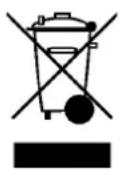
Use proper local collecting centers meeting local legislation when handling waste of electrical and electronic equipment.

WARNING!
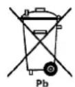
HAZARDOUS MATERIALS. Batteries may contain HIGH VOLTAGES, and CAUSTIC, TOXIC and FLAMMABLE substances. Batteries can injure or kill people and damage equipment if used improperly. DO NOT DISCARD unwanted batteries or battery material in the public waste disposal system. Follow ALL applicable, local regulations for storage, handling and disposal of batteries and battery materials.
11. Dimensional drawings
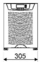
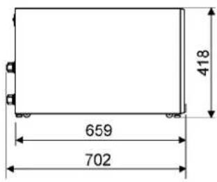
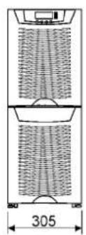
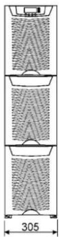
Figure 47. UPS models with no battery sections.
natural_image
Technical line drawing of a cylindrical device with internal grid structure and dimension label (305), no readable text or symbols present.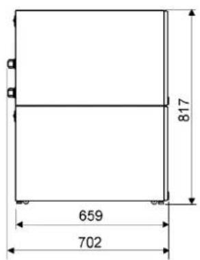
natural_image
Diagram of a multi-tiered cylindrical device with internal mesh structure, labeled 305 (no text or symbols beyond dimension)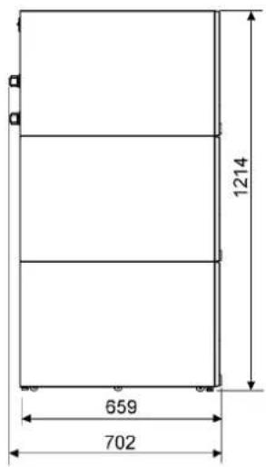
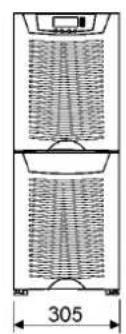
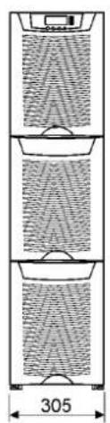
Figure 48. UPS models with (1) and (2) battery bottom sections.
natural_image
Technical drawing of a cylindrical device with internal grid pattern and dimension label (305), no readable text or symbols beyond measurement markers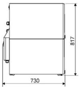
natural_image
Diagram of three vertical structural layers with internal patterns and a dimension label '305' (no text or symbols within the diagram itself)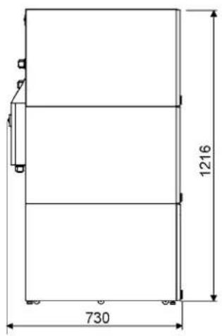
Figure 49. UPS models with (1) and (2) battery bottom sections plus integrated MBS.
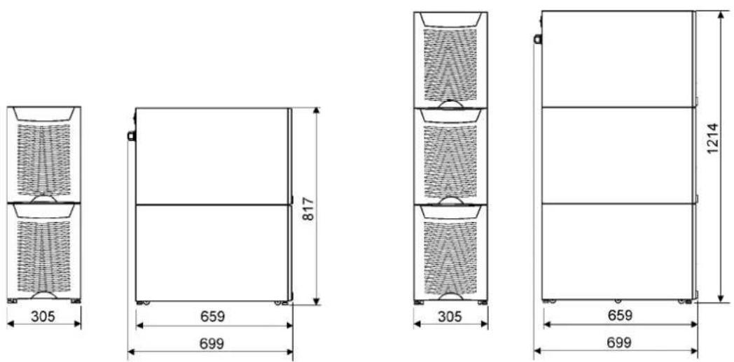
Figure 50. External battery cabinet models with (2) and (3) sections.
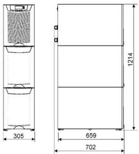
Figure 51. UPS models with middle battery and bottom transformer sections.
12. Technical data
Standards
| UPS 8 kVA 10 kVA 12 kVA 15 kVA | |||
| Safety IEC 62040-1-1, EN 62040-1-1 and EN 60950 | |||
| EMC EN 50091-2 | |||
| Product IEC 62040-3 and EN 62040-3 | |||
Environment
| UPS 8 kVA 10 kVA 12 kVA 15 kVA | |||
| Amb. temperature 0 to +40°C (electronics), 15 to +25°C (batteries) | |||
| Relative humidity | 0 to 95%, no condensation allowed | ||
| Altitude | <1000 m above sea level at +40°C | ||
| Vibration | IEC 68-2-6; max. 0.3 mm (2 to 9 Hz), max. 1 m/s2 (9 to 200 Hz) sinusoidal | ||
Mechanical configuration
| UPS | 8 kVA | 10 kVA | 12 kVA | 15 kVA |
| Dimensions | ||||
| - Width | 305 mm | |||
| - Depth | 702 mm | |||
| - Height | 817 mm (32 bat) or 1214 mm (64 bat) | |||
| Weight | ||||
| - no battery | 75 kg | |||
| - 32 battery | 165 kg | |||
| - 64 battery | 275 kg | |||
| - 32 battery and transformer | 280 kg | |||
| - MBS | +17 kg | |||
| Colour | RAL 9005 black | |||
Characteristics
| UPS | 8 kVA | 10 kVA | 12 kVA | 15 kVA |
| Efficiency- nominal load | Up to 92% | Up to 92% | Up to 92% | Up to 93% |
| Heat losses | <580 W | <720 W | <870 W | <1050 W |
| Backup time- load pf 0.7- temperature+25°C | 10 min (32 bat 7 Ah)15 min (32 bat 9 Ah)28 min (64 bat 7 Ah)33 min (64 bat 9 Ah) | 6 min (32 bat 7 Ah)10 min (32 bat 9 Ah)20 min (64 bat 7 Ah)28 min (64 bat 9 Ah) | 8 min (32 bat 9 Ah)15 min (64 bat 7 Ah)20 min (64 bat 9 Ah) | 5 min (32 bat 9 Ah)10 min (64 bat 7 Ah)15 min (64 bat 9 Ah) |
| Noise (ISO 7779) | 50 - 53 dB(A) depending on the load | |||
AC input
| UPS 8 kVA 10 kVA 12 kVA | 15 kVA | |||
| Rectifier input 3-phases | ||||
| Bypass input 3-phases | ||||
| Voltage tolerance 196-253 | V and 339-438 V | |||
| Frequency 45 Hz to 65 Hz | ||||
| Power factor 0.99 | ||||
| Input distortion < 5% THD(I) | ||||
| Rated input current 12 A | 15 A | 17 A 22 A | ||
DC circuit
| UPS | 8 kVA | 10 kVA | 12 kVA 15 kVA |
| Management Advanced Battery Management | |||
| Nominal voltage | 384 Volts | ||
| Battery qty | 32 /module | ||
| Float voltage | 2.30 VPC | ||
| Battery type | VRLA 12 Volts | ||
| Cut off voltage | 1.75 VPC | ||
| Battery charging | 3 A, user selectable | ||
AC output
| UPS | 8 kVA | 10 kVA 12 kVA | 15 kVA | |
| Active power | 7,2 kW | 9 kW | 10,8 kW | 13.5 kW |
| Nro. of phases | 3-phases | |||
| Frequency | 50 Hz or 60 Hz, user selectable | |||
| Voltage | 380, 400 or 415 Volts, user selectable | |||
| Short circuit capability | 55 A, < 300 ms | |||
| Overload capability | 10 min >100-110% load1 min >110-125% load5 sec >125-150% load300 ms >150% load | |||
| Overload capability (mains available) | 60 min >100 - 110% load10 min >110 - 125% load1 min >125 - 150% load | |||
13. Warranty
The product is warranted against defects in design, materials and workmanship for a period of twelve (12) months from its original date of purchase. The local office or distributor may grant a warranty period different to the above and refer to local terms of liability as defined in the supply contract.
The UPS manufacturer is not responsible for
- Any costs resulting from a failure if the installation, commissioning, repair, alternation, or ambient conditions of the equipment do not fulfil the requirements specified in the documentation delivered with the unit and other relevant documentation.
- Equipment subjected to misuse, negligence or accident
- Equipment comprised of materials provided or designs stipulated by the purchaser.
Under no circumstances shall the manufacturer, its suppliers or subcontractors be liable for special, indirect, incidental or consequential damages, losses or penalties.
The technical data, information and specifications are valid at the time of printing. The UPS manufacturer reserves the right to modifications without prior notice.
- UPS 8 – 15 kVA, 400 V 50/60 Hz
- User's Guide 1023625 revision C
- Contents
- Safety instructions ....4
- Mechanical installation....6
- Planning before installation....8
- Cabinet installation....9
- Electrical installation....13
- Software and connectivity....20
- User operations....26
- Maintenance 32
- Parallel systems 37
- Recycling the used UPS or batteries 45
- Dimensional drawings 47
- Technical data....48
- Warranty....50
- Safety instructions
- Warning!
- Audience
- Note!
- CE marking
- User precautions
- Environment
- Inquiries
- Mechanical installation
- Delivery check
- Unpacking and visual inspection
- Planning before installation
- Cabinet installation
- Maintenance bypass switch
- Transformer option
- External battery cabinet option
- Battery racks
- Electrical installation
- UPS TERMINALS:
- MBS TERMINALS:
- Power cables and protective fuses
- Wiring procedure
- External Battery Cabinet (EBC) installation procedure
- Software and connectivity
- Communication cables
- Connection to the standard RS-232 port (X53)
- LanSafe software
- External control connections
- Emergency Power Off (EPO)
- Relay outputs
- Programmable signal inputs
- XSlot communication (option)
- Web/SNMP Module (optional)
- AS400 Relay Module (optional)
- Single Serial Port Module (optional)
- Modus/Jbus Module (optional)
- User operations
- Display functions
- User Settings
- Configuring user settings
- Changing language
- Changing charging current
- Using relay outputs
- Normal start-up
- Check
- Battery start-up
- Start-up after EPO
- Shutdown
- Maintenance
- Regular service/intervals
- Batteries
- Cooling fan
- LED Indicators
- Maintenance bypass switch (MBS) operation
- Turn UPS from normal mode to mechanical bypass
- No break transfer from normal mode to Service Bypass:
- Turn UPS from mechanical bypass to normal mode
- Parallel systems
- Overview
- Tie cabinets
- XSlot Hot Sync card: installing and wiring
- Parallel operations
- Recycling the used UPS or batteries
- Dimensional drawings
- Technical data
- Warranty
Brand : EATON
Model : Powerware 9355-15-N-15-64x9Ah
Category : Uninterruptible power supply