NPort 5630-16 - Server Moxa - Free user manual and instructions
Find the device manual for free NPort 5630-16 Moxa in PDF.


| Product Type | 16-Port Serial Device Server |
| Serial Ports | 16 x RS-232/422/485 DB9 male |
| Ethernet Port | 1 x 10/100BaseT(X) RJ45 |
| Power Input | 100-240 VAC, 50-60 Hz or 48 VDC (optional) |
| Power Consumption | 12.5 W (max) |
| Dimensions (W x D x H) | 440 x 250 x 44 mm (1U rackmount) |
| Weight | 3.2 kg (7.1 lb) |
| Operating Temperature | 0 to 60°C (32 to 140°F) |
| Storage Temperature | -20 to 80°C (-4 to 176°F) |
| Relative Humidity | 5 to 95% (non-condensing) |
| Protocols Supported | TCP, UDP, DHCP, SNMP, HTTP, Telnet, SSH |
| Configuration Interface | Web browser, Telnet, serial console, utility software |
| Serial Communication Parameters | baud rate 50-921.6 kbps, data bits 5,6,7,8, stop bits 1,1.5,2, parity none, even, odd, space, mark |
| Flow Control | RTS/CTS, XON/XOFF |
| Management | SNMP MIB-II, RMON, syslog, email alert |
| Security | Password protection, IP filtering, HTTPS, SSH |
| Maintenance | Firmware upgrade via web or utility, factory reset button |
| Cleaning | Use a dry soft cloth; avoid liquids and abrasives |
| Safety Certifications | UL, CE, FCC, Class A |
| Spare Parts & Repairability | Power supply unit, fan module; contact Moxa support |
| Warranty | 5 years (standard) |
Frequently Asked Questions - NPort 5630-16 Moxa
User questions about NPort 5630-16 Moxa
0 question about this device. Answer the ones you know or ask your own.
Ask a new question about this device
Download the instructions for your Server in PDF format for free! Find your manual NPort 5630-16 - Moxa and take your electronic device back in hand. On this page are published all the documents necessary for the use of your device. NPort 5630-16 by Moxa.
USER MANUAL NPort 5630-16 Moxa
NPort 5600 Series User's Manual
Ninth Edition, June 2008
www.moxa.com/product
MOXA®
© 2008 Moxa Inc., all rights reserved. Reproduction without permission is prohibited.
NPort 5600 Series User's Manual
The software described in this manual is furnished under a license agreement and may be used only in accordance with the terms of that agreement.
Copyright Notice
Copyright © 2008 Moxa Inc.
All rights reserved.
Reproduction without permission is prohibited.
Trademarks
MOXA is a registered trademark of Moxa Inc
All other trademarks or registered marks in this manual belong to their respective manufacturers.
Disclaimer
Information in this document is subject to change without notice and does not represent a commitment on the part of Moxa.
Moxa provides this document “as is,” without warranty of any kind, either expressed or implied, including, but not limited to, its particular purpose. Moxa reserves the right to make improvements and/or changes to this manual, or to the products and/or the programs described in this manual, at any time.
Information provided in this manual is intended to be accurate and reliable. However, Moxa assumes no responsibility for its use, or for any infringements on the rights of third parties that may result from its use.
This product might include unintentional technical or typographical errors. Changes are periodically made to the information herein to correct such errors, and these changes are incorporated into new editions of the publication.
Technical Support Contact Information
www.moxa.com/support
Moxa Americas:
Toll-free: 1-888-669-2872
Tel: +1-714-528-6777
Fax: +1-714-528-6778
Moxa China (Shanghai office):
Toll-free: 800-820-5036
Tel: +86-21-5258-9955
Fax: +86-10-6872-3958
Moxa Europe:
Tel: +49-89-3 70 03 99-0
Fax: +49-89-3 70 03 99-99
Moxa Asia-Pacific:
Chapter 1 Introduction....1-1
Overview 1-2
Package Checklist 1-2
Product Features.... 1-2
Product Specifications.... 1-3
Chapter 2 Getting Started....2-1
Panel Layout.... 2-2
Connecting the Hardware....2-3
Wiring Requirements 2-3
Connecting NPort 5610/30/50-16/8's Power 2-3
Connecting NPort 5610-16/8-48V's Power 2-3
Grounding NPort 5610-16/8-48V 2-4
Connecting to the Network 2-4
Connecting to a Serial Device....2-5
LED Indicators 2-5
Link Indicator on the Rear Panel of NPort 5650 Fiber Model....2-5
Real Time Clock 2-5
Adjustable Pull High/low Resistors for the RS-485 Port 2-5
Chapter 3 Initial IP Address Configuration....3-1
Initializing NPort's IP Address.... 3-2
Factory Default IP Address 3-2
LCM Display 3-2
NPort Administration Suite 3-5
ARP 3-5
Telnet Console 3-6
Chapter 4 Choosing the Proper Operation Mode....4-1
Overview 4-2
Real COM Mode 4-2
TCP Server Mode 4-3
TCP Client Mode 4-4
UDP Mode....4-4
Pair Connection Mode....4-4
Reverse Telnet Mode.... 4-5
Disabled Mode 4-5
RFC2217 Mode 4-5
PPP Mode 4-6
Chapter 5 Web Console Configuration ....5-1
Opening Your Browser 5-2
Basic Settings....5-3
Network Settings 5-5
Serial Settings.... 5-9
Operating Settings....5-11
Real COM Mode....5-11
TCP Server Mode 5-14
TCP Client Mode 5-18
UDP Mode 5-23
Pair Connection Mode 5-25
Reverse Telnet Mode 5-27
Disabled Mode....5-28
RFC2217 Mode....5-28
PPP Mode 5-30
Accessible IP Settings 5-31
PPP User Table 5-32
Auto Warning Settings 5-33
Auto warning: E-mail and SNMP Trap....5-33
Event Type 5-34
Monitor....5-36
Monitor Line 5-36
Monitor Async 5-36
Monitor Async-Settings 5-37
Change Password 5-37
Load Factory Defaults.... 5-38
Chapter 6 Configuring NPort Administrator....6-1
Overview....6-2
Installing NPort Administrator 6-2
Configuration 6-5
Broadcast Search....6-6
Unlock Password Protection 6-7
Configuring NPort 5600....6-10
Upgrading Firmware 6-12
Export/Import 6-13
Monitor....6-14
Port Monitor 6-20
COM Mapping 6-20
IP Serial LIB Function Groups....7-3
Example Program....7-3
Appendix A Pinouts and Cable Wiring....A-1
Port Pinout Diagrams A-2
Ethernet Port Pinouts ...... A-2
Serial Port Pinouts....A-2
Cable Wiring Diagrams A-3
Ethernet Cables A-3
Serial Cables for NPort 5610/5650 (RS-232)...... A-3
Serial Cables for NPort 5630 (RS-422/4-wire RS-485)...... A-5
Serial Cables for NPort 5630 (2-wire RS-485) A-6
Serial Cables for NPort 5650 (RS-422/4-wire RS-485)...... A-7
Serial Cables for NPort 5650 (2-wire RS-485) ...... A-8
Pin Assignments for DB9 and DB25 Connectors....A-9
Appendix B Well Known Port Numbers ...... B-1
Appendix C SNMP Agent with MIB II & RS-232 Like Group ...... C-1
Appendix D Auto IP Report Protocol....D-1
The Moxa NPort 5600 Series of advanced serial device servers make it easy to network-enable your serial devices. The NPort 5600 Series includes 8 models: NPort 5610-16, NPort 5610-8 (8 or 16 RS-232 ports, with AC power), NPort 5610-16-48V, NPort 5610-8-48V (8 or 16 RS-232 ports, with DC power), NPort 5630-16, NPort 5630-8 (8 or 16 RS-422/485 ports, with AC power), and NPort 5650-16, NPort 5650-8 (8 or 16 RS-232/422/285 ports, with AC power). In this manual, we often refer to the eight products collectively as “5600” or “5600 Series.”
The following topics are covered in this chapter:
Overview
□ Package Checklist
□ Product Features
□ Product Specifications
Overview
The NPort 5600 Series serial device servers are designed to make your industrial serial devices Internet ready instantly. The compact size of the NPort 5600 device servers makes them the ideal choice for connecting your RS-232 (NPort 5610-16/8), RS-422/485 (NPort 5630-16/8), or RS-232/422/485 (NPort 5650-16/8) serial devices—such as PLCs, meters, and sensors—to an IP-based Ethernet LAN, making it possible for your software to access serial devices anywhere over a local LAN or the Internet.
The NPort 5600 serial device servers ensure the compatibility of network software that uses a standard network API (Winsock or BSD Sockets) by providing TCP Server Mode, TCP Client Mode, and UDP Mode. And thanks to NPort's Real COM/TTY drivers, software that works with COM/TTY ports can be set up to work over a TCP/IP network in no time. This excellent feature preserves your software investment and lets you enjoy the benefits of networking your serial devices instantly.
The NPort 5600 serial device servers support automatic IP configuration protocols (DHCP, BOOTP) and manual configuration via NPort's handy web browser console. Both methods ensure quick and effective installation, and by using NPort 5600's Windows Utility, installation is very straightforward, since all system parameters can be stored and then copied to other device servers simultaneously.
Package Checklist
The Moxa NPort 5600 Series products are shipped with the following items:
Standard Accessories
• 1 16- or 8-port serial device server
• NPort Documentation & Software CD
• NPort 5600 Quick Installation Guide
- Power cord
Optional Accessories
• CBL-RJ45M9-150 RJ45 8-pin to DB9 Male cable, 150 cm
• CBL-RJ45F9-150 RJ45 8-pin to DB9 Female cable, 150 cm
• CBL-RJ45M25-150 RJ45 8-pin to DB25 Male cable, 150 cm
• CBL-RJ45F25-150 RJ45 8-pin to DB25 Female cable, 150 cm
NOTE: Notify your sales representative if any of the above items is missing or damaged.
Product Features
The NPort 5600 Series products have the following features:
• Make your serial devices Internet ready
- Easy-to-use LCM (Liquid Crystal Module) interface for setting up the IP address
- Versatile socket operation modes, including TCP Server, TCP Client, and UDP
- Easy-to-use Windows Utility for mass installation
• Supports 10/100 Mbps Ethernet—auto-detectable
• Supports 16/8-port RS-232 or RS-422/485 interface or RS-232/422/485 interface
• Built-in 15 KV ESD protection for all serial signals
• Supports SNMP MIB-II for network management
Product Specifications
LAN
Ethernet 10/100 Mbps, RJ45
Protection Built-in 1.5 KV magnetic isolation
Optical Fiber
Distance Multi mode: 0 to 2 km, 1310 nm (62.5/125 μm, 500 MHz*km) Single mode: 0 to 40 km, 1310 nm (9/125 μm, 3.5 PS/(nm*km))
Min. TX Output Multi mode: -20 dBm Single mode: 0 to 40 km, -5 dBm
Max. TX Output Multi mode: -14 dBm Single mode: 0 to 40 km, 0 dBm
Sensitivity -36 to -32 dBm (Single), -34 to -30 dBm (Multi)
NPort 5610 Serial Interface
Interface RS-232
No. of Ports 16/8
Port Type RJ45 8-pin
Signals TxD, RxD, RTS, CTS, DTR, DSR, DCD, GND
Serial Line Protection 15 KV ESD for all signals
NPort 5630 Serial Interface
Interface RS-422/485
No. of Ports 16/8
Port Type RJ45 8-pin
Signals RS-422: Tx+, Tx-, Rx+, Rx-, GND
RS-485 (2-wire): Data+, Data-, GND
RS-485 (4-wire): Tx+, Tx-, Rx+, Rx-, GND
Serial Line Protection 15 KV ESD for all signals
RS-485 Data Direction ADDCTM (Automatic Data Direction Control)
NPort 5650 Serial Interface
Interface RS-232/422/485
No. of Ports 16/8
Port Type RJ45 8-pin
Signals RS-232: TxD, RxD, RTS, CTS, DTR, DSR, DCD, GND
RS-422: Tx+, Tx-, Rx+, Rx-, GND
RS-485 (2-wire): Data+, Data-, GND
RS-485 (4-wire): Tx+, Tx-, Rx+, Rx-, GND
Serial Line Protection 15 KV ESD for all signals RS-485 Data Direction ADDC™ (Automatic Data Direction Control)
Power Line Protection
4 KV Burst (EFT), EN61000-4-4
2 KV Surge, EN61000-4-5
Advanced Built-in Features
HMI LCM display with four push buttons
Buzzer
Real-Time Clock
Watch Dog Timer
Serial Communication Parameters
Parity None, Even, Odd, Space, Mark
Data Bits 5, 6, 7, 8
Stop Bit 1, 1.5, 2
Flow Control RTS/CTS, XON/XOFF, DSR/DTR (Excluded NPort 5630)
Transmission Speed 50 bps to 921.6 Kbps
Software Features
Protocols ICMP, IP, TCP, UDP, DHCP, BOOTP, Telnet, DNS, SNMP, HTTP, SMTP, SNTP, Rtelnet, ARP, PPP, RFC2217
Utilities NPort Administrator for Windows 98/ME/NT/2000/XP/2003/Vista/2008/XP x64/2003 x64/Vista x64/2008 x64
OS Driver Support Real COM drivers for: Windows 95/98/ME/NT/2000/XP/Vista/2008/XP x64/2003/2003 x64/Vista x64/2008 x64 Real TTY driver for: Linux 2.4.x, 2.6.x kernel Fixed TTY drivers for: SCO Unix, SCO OpenServer 5, OpenServer 6, UnixWare 7, UnixWare 2.1, SVR4.2, QNX 4.25, QNX 6, Solaris 10, FreeBSD 5, FreeBSD 6
Configuration Web Browser, Telnet Console, or Windows Utility
Power Requirements
Power Input 100 to 240 VAC, 47 to 63 Hz, or ±48 VDC (20 to 72 VDC, -20 to -72 VDC)
Power Consumption NPort 5610-16/8: 141 mA for 100V, 93 mA for 240V
NPort 5610-16/8-48V: 135 mA (at 48V max.)
NPort 5630-16/8: 152 mA for 100V, 98 mA for 240V
NPort 5650-8/16: 158 mA @ 100 VAC, 102 mA @ 240 VAC
NPort 5650-S-SC-8/16: 164 mA @ 100 VAC, 110 mA @ 240 VAC
NPort 5650-M-SC-8/16: 174 mA @ 100 VAC, 113 mA @ 240 VAC
Mechanical
Material SECC sheet metal (1 mm)
Dimensions (W× H× D) 190× 44.5× 478~mm (including ears)
190 × 44.5 × 440 mm (without ears)
Environment
Operating Temperature 0 to 55°C (32 to 131°F), 5 to 95%RH
Storage Temperature -20 to 85°C (-4 to 185°F), 5 to 95%RH
Regulatory Approvals
EMC FCC Class A, CE Class A
Safety UL, CUL, TÜV
WARRANTY 5 years
This chapter includes information about installing NPort 5600 Series. The following topics are covered:
Panel Layout
□ Connecting the Hardware
Wiring Requirements
Connecting NPort 5610/30/50-16/8's Power
Connecting NPort 5610-16/8-48V's Power
▶ Grounding NPort 5610-16/8-48V
▶ Connecting to the Network
▶ Connecting to a Serial Device
▶ LED Indicators
- Link Indicator on the Rear Panel of NPort 5650 Fiber Model
Real Time Clock
Adjustable Termination Resistor for the RS-485 Port
Panel Layout
The following figures depict the front and rear panels of the NPort 5600 series.
Front panel of NPort 5600 series

Rear panel of NPort 5600 series (AC Power)

Rear panel of NPort 5600 series (DC Power)

Rear panel of NPort 5650 Fiber model

Reset Button—Press the Reset button continuously for 5 sec to load factory defaults: Use a pointed object, such as a straightened paper clip or toothpick, to press the reset button. This will cause the Ready LED to blink on and off. The factory defaults will be loaded once the Ready LED stops blinking (after about 5 seconds). At this point, you should release the reset button.
Connecting the Hardware
This section describes how to connect NPort 5600 Series to serial devices for first time testing purposes. We cover Wiring Requirements, Connecting NPort 5610/30/50-16/8's Power, Connecting NPort 5610-16/8-48V's Power, Grounding NPort 5610-16/8-48V, Connecting to the Network, Connecting to a Serial Device, and LED Indicators.
Wiring Requirements

ATTENTION
Safety First!
Be sure to disconnect the power cord before installing and/or wiring your NPort 5600 Series.
Wiring Caution!
Calculate the maximum possible current in each power wire and common wire. Observe all electrical codes dictating the maximum current allowable for each wire size.
If the current goes above the maximum ratings, the wiring could overheat, causing serious damage to your equipment.
Temperature Caution!
Please take care when handling NPort 5600. When plugged in, NPort 5600's internal components generate heat, and consequently the casing may feel hot to the touch.
You should also pay attention to the following points:
- Use separate paths to route wiring for power and devices. If power wiring and device wiring paths must cross, make sure the wires are perpendicular at the intersection point.
NOTE: Do not run signal or communication wiring and power wiring in the same wire conduit. To avoid interference, wires with different signal characteristics should be routed separately.
- You can use the type of signal transmitted through a wire to determine which wires should be kept separate. The rule of thumb is that wiring that shares similar electrical characteristics can be bundled together.
- Keep input wiring and output wiring separate.
• Where necessary, it is strongly advised that you label wiring to all devices in the system.
Connecting NPort 5610/30/50-16/8's Power
Connect NPort 5610/30-16/8's 100-240 VAC power line with its AC connector. If the power is properly supplied, the "Ready" LED will show a solid red color until the system is ready, at which time the "Ready" LED will change to a green color.
Connecting NPort 5610-16/8-48V's Power
To connect NPort 5610-16/8-48V's power cord with its terminal block, follow the steps given below:
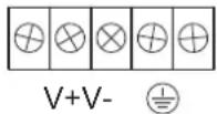
- Loosen the screws on the V_+ and V_- terminals of NPort 5610-16/8-48V's terminal block.
- Connect the power cord's 48 VDC wire to the terminal block's V+ terminal, and the power cord's DC Power Ground wire to the terminal block's V- terminal, and then tighten the terminal block screws. (Note: NPort 5610-16/8-48V can still operate even if the DC 48V and DC Power Ground are reversed.)
If the power is properly supplied, the “Ready” LED will show a solid red color until the system is ready, at which time the “Ready” LED will change to a green color.
NOTE
You should use 8 kg-cm of screw torque and 22-14 AWG of suitable electric wire to connect NPort 5610-16/8-48V's power cord to its terminal block.
Grounding NPort 5610-16/8-48V
Grounding and wire routing helps limit the effects of noise due to electromagnetic interference (EMI). Run the ground connection from the ground screw to the grounding surface prior to connecting devices.
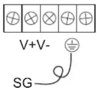
The Shielded Ground (sometimes called Protected Ground) contact is the second contact from the right of the 5-pin power terminal block connector located on the rear panel of NPort 5610-16-48V/5610-8-48V. Connect the SG wire to the Earth ground.

ATTENTION
This product is intended to be mounted to a well-grounded mounting surface such as a metal panel.
Connecting to the Network
Connect one end of the Ethernet cable to NPort 5600's 10/100M Ethernet port and the other end of the cable to the Ethernet network. There are 2 LED indicators located on the bottom left and right corners of the Ethernet connector. If the cable is properly connected, NPort 5600 will indicate a valid connection to the Ethernet in the following ways:
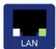
The bottom right corner LED indicator maintains a solid green color when the cable is properly connected to a 100 Mbps Ethernet network.
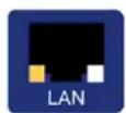
The bottom left corner LED indicator maintains a solid orange color when the cable is properly connected to a 10 Mbps Ethernet network.
Connecting to a Serial Device
Connect the serial data cable between NPort 5600 and the serial device.
LED Indicators
The front panels of NPort 5600 have several LED indicators, as described in the following table.
| LED Name | LED Color | LED | Function |
| Ready | off Power | is off, or power error condition exists. | |
| red | Steady on: Power is on and NPort is booting up. | ||
| Blinking: Indicates an IP conflict, or DHCP or BOOTP server did not respond properly. | |||
| green | Steady on: Power is on and NPort is functioning normally. | ||
| Blinking: The NPort has been located by NPort Administrator's Location function. | |||
| 1-16 | orange Serial port is receiving data. | ||
| green Serial port is transmitting data. | |||
| off | No data is being transmitted or received through the serial port. | ||
Link Indicator on the Rear Panel of NPort 5650 Fiber Model
The rear panels of NPort 5600 have a link indicator, as described in the following table.
| LED Name | LED Color | LED Function |
| Link | off Fiber | |
| green Fiber | ||
| blinking Fiber | ||
Real Time Clock
NPort 5600's real time clock is powered by a lithium battery. We strongly recommend that you do not replace the lithium battery without the presence of Moxa's technical support engineers. If you need a battery change, contact Moxa for assistance.

ATTENTION
There is risk of explosion if the battery is replaced by an incorrect type. You need to dispose used batteries according to the instructions.
Adjustable Pull High/low Resistors for the RS-485 Port
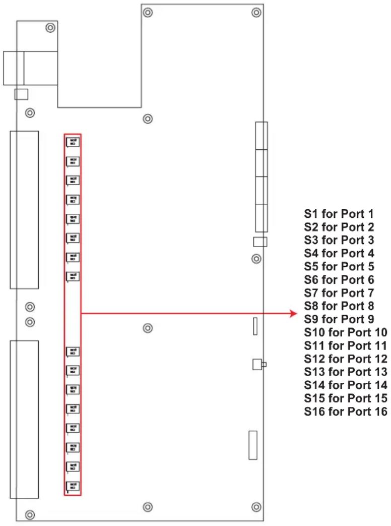
In some critical environments, you may need to add termination resistors to prevent the reflection of serial signals. When using termination resistors, it is important to set the pull high/low resistors correctly so that the electrical signal is not corrupted. Since a particular pull high/low resistor value cannot fit all environments, the NPort 5650 uses DIP switches to set the pull high/low resistor values for each serial port.
To set the pull high/low resistors to 150 KΩ, make sure both of the assigned DIP switches are in the OFF position. This is the default setting.
To set the pull high/low resistors to 1 KΩ, make sure both of the assigned DIP switches are in the ON position.

ATTENTION
Do not use the 1 KΩ setting on the NPort 5650 when using the RS-232 interface. Doing so will degrade the RS-232 signals and shorten the maximum allowed communication distance.
NPort 5650 DIP Switches
When setting up your NPort 5600 for the first time, the first thing you should do is configure the IP address. This chapter introduces several methods to configure NPort's IP address. Select the method that is the most convenient for you. For more details about network settings, see the Network Settings section from Chapter 5, Web Console Configuration.
This chapter includes the following sections:
☐ Initializing NPort's IP Address
□ Factory Default IP Address
☐ LCM Display ← recommended configuration method
☐ NPort Administration Suite ← recommended configuration method
ARP
Telnet Console
Initializing NPort's IP Address
- Determine whether your NPort needs to use a Static IP or Dynamic IP (either DHCP or BOOTP application).
- If NPort is used in a Static IP environment, you can use NPort Administration Suite, ARP, Web Console, or Telnet Console to configure the new IP address.
- If NPort is used in a Dynamic IP environment, you can use NPort Administration suite, Web Console, or Telnet Console to configure NPort to get an IP address dynamically with DHCP, DHCP/BOOTP, or BOOTP.

ATTENTION
Consult your network administrator on how to reserve a fixed IP address (for your NPort) in the MAC-IP mapping table when using a DHCP Server or BOOTP Server. In most applications, you should assign a fixed IP address to your NPort.
Factory Default IP Address
NPort products are configured with the following default private IP address:
Default IP address: 192.168.127.254
(IP addresses of the form 192.168.xxx.xxx are referred to as private IP addresses, since it is not possible to directly access a device configured with a private IP address from a public network. For example, you would not be able to ping such a device from an outside Internet connection. NPort applications that require sending data over a public network, such as the Internet, require setting up the server with a valid public IP address, which can be leased from a local ISP.)
LCM Display
We recommend using the LCM display and four push buttons to configure the IP address for the first time.
Basic Operation
If the NPort is working properly, the LCM panel will display a green color. The red Ready LED will also light up, indicating that the NPort is receiving power. After the red Ready LED turns green, you will see a display similar to:
| N | P | 5 | 6 | 1 | 0 | - | 1 | 6 | _ | 3 | 8 | |||
| 1 | 9 | 2 | . | 1 | 6 | 8 | . | 1 | 2 | 7 | . | 2 | 5 | 4 |
Where
• NP5610-16 is the NPort's name
- 38 is the NPort's serial number
- 192.168.127.254 is the NPort's IP address
There are four push buttons on NPort's nameplate. Going from left to right, the buttons are:
| Button | Name | Action |
| MENU menu activates the | main menu, or returns to an upper level | |
| up cursor | scrolls up through a list of items shown on the LCM panel’s second line | |
| down cursor | scrolls down through a list of items shown on the LCM panel’s second line | |
| SEL | select | selects the option listed on the LCM panel’s second line |
The buttons are manipulated in a manner similar to the way a modern cellular phone operates. As you move through the various functions and setting options, note that the top line shows the current menu or submenu name, and the bottom line shows the submenu name or menu item that is activated by pressing the SEL button.
Detailed Menu Options
The best way to explain all of NPort's LCM functions is to refer to the table shown on the next page. There are three main levels—1, 2, and 3—with each level represented by a separate column.
The first thing to remember is that the MENU button is used to move back and forth between the LCM panel's default screen, and main menu screen:
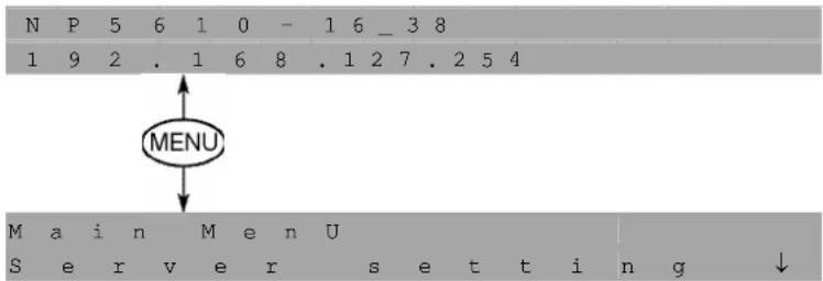
In addition, you only need to remember to:
- Use the SEL button to move up one level (i.e., left to right on the tree graph)
- Use the MENU button to move down one level (i.e., right to left on the tree graph)
- Use the cursor keys, and , to scroll between the various options within a level (i.e., up and down on the tree graph).
As you use the buttons to operate the LCM display, you will notice that with very few exceptions, moving up one level causes the bottom line of the display to move to the top line of the display. You will also notice that the bottom three options in level 2, and all of the options in level 3 have either a C or D attached. The meaning is as follows:
- C = configurable (i.e., you are allowed to change the setting of this option)
- D = display only (i.e., the setting for this option is displayed, but it cannot be changed) This does NOT necessarily mean that the number does not change; only that you cannot change it.
| Level 1 Level | 2 Level 3 | |||||
| Main Menu | ||||||
| Server setting | Serial number | D | ||||
| Server name | C | |||||
| Firmware ver | D | |||||
| Model name | D | |||||
| Network setting | Ethernet status | D | ||||
| MAC address | D | |||||
| IP config | C | |||||
| IP address | C | |||||
| Netmask | C | |||||
| Gateway | C | |||||
| DNS server 1 | C | |||||
| DNS server 2 | C | |||||
| Serial set Select port | Baudrate | C | ||||
| Data bit | C | |||||
| Stop bit | C | |||||
| Parity | C | |||||
| Flow control | C | |||||
| Tx/Rx fifo | C | |||||
| Interface | C | |||||
| Tx/Rx bytes | D | |||||
| Line status | D | |||||
| Op Mode set | Select port | C | ||||
| Select mode [mode] | C | |||||
| Real COM | TCP server | TCP client | UDP svr/cli | |||
| Alive timeout | Alive timeout | Alive timeout | Delimiter 1 | C | ||
| Max connection | Inact. time | Inact. time | Delimiter 2 | C | ||
| Delimiter 1 | Max connection | Delimiter 1 | Force Tx | C | ||
| Delimiter 2 | Delimiter 1 | Delimiter 2 | Dest IP start-1 | C | ||
| Force Tx | Delimiter 2 | Force Tx | Dest IP end-1 | C | ||
| Force Tx | Dest IP-1 | Dest port-1 | C | |||
| Local TCP port | TCP port-1 | Dest IP start-2 | C | |||
| Dest IP-2 | Dest IP end-2 | C | ||||
| TCP port-2 | Dest port-2 | C | ||||
| Dest IP-3 | Dest IP start-3 | C | ||||
| TCP port-3 | Dest IP end-3 | C | ||||
| Dest IP-4 | Dest port-3 | C | ||||
| TCP port-4 | Dest IP start-4 | C | ||||
| TCP connect | Dest IP end-4 | C | ||||
| Dest port-4 | C | |||||
| Local port | C | |||||
| Console | Web console | C | ||||
| Telnet console | C | |||||
| Ping | C | |||||
| Save/Restart | C | |||||
The part of the LCM operation that still requires some explanation is how to edit the configurable options. In fact, you will only encounter two types of configurable options.
The first type involves entering numbers, such as IP addresses, Netmasks, etc. In this case, you change the number one digit at a time. The up cursor ( ) is used to decrease the highlighted digit, the down cursor ( ) is used to increase the highlighted digit, and the sel button is used to move to the next digit. When the last digit has been changed, pressing sel simply enters the number into NPort 5600 Series' memory.
The second type of configurable option is when there are only a small number of options from which to choose (although only one option will be visible at a time). Consider the
Parity attribute under Serial set as an example. Follow the tree graph to arrive at the following Parity screen. The first option, None, is displayed, with a down arrow all the way to the right. This is an indication that there are other options from which to choose.
| P | a | r | i | t | Y | |
| N | O | n | e | ↓ |
Press the down cursor button once to see Odd as the second option.

Press the down cursor button again to see Even as the third option.

Press the down cursor button again to see Space as the fourth option.

Press the down cursor button yet again to see the last option, Mark.
| P | a | r | i | t | Y | |
| M | a | r | k | ↓ |
To choose the desired option, press the SEL button when the option is showing on the screen.
NPort Administration Suite
NPort Administration Suite consists of some useful utility programs that are used to configure and manage your NPorts.
See Chapter 6 for details on how to install NPort Administration Suite, and how to use this suite of useful utilities to set up IP addresses and configure your NPort.
ARP
You can make use of the ARP (Address Resolution Protocol) command to set up an IP address for your NPort. The ARP command tells your computer to associate the NPort's MAC address with the intended IP address. You must then use Telnet to access the NPort, at which point the Device Server's IP address will be reconfigured.

ATTENTION
In order to use this setup method, both your computer and NPort must be connected to the same LAN.
Or, you may use a cross-over Ethernet cable to connect the NPort directly to your computer's Ethernet card.
Your NPort must be configured with the factory default IP address—192.168.127.254—before executing the ARP command, as described below.
Take the following steps to use ARP to configure the IP address:
- Obtain a valid IP address for your NPort from your network administrator.
- Obtain the NPort's MAC address from the label on its bottom panel.
- Execute the 'arp -s' command from your computer's MS-DOS prompt by typing:
arp -s 192.168.200.100 00-90-E8-xx-xx-xx
This is where 192.168.200.100 is the new IP address and 00-90-E8-xx-xx-xx is the MAC address for your NPort. You will need to change both numbers, as described above in points 1 and 2.
- Next, execute a special Telnet command by typing:
telnet 192.168.200.100 6000
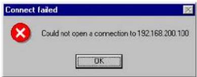
After issuing this command, a Connect failed message will appear, as shown here. After the NPort reboots, its IP address should be updated to the new address, and you can reconnect using Telnet, Web, or Administrator to check that the update was successful.
Telnet Console
Depending on how your computer and network are configured, you may find it convenient to use network access to set up your NPort's IP address. This can be done using the Telnet program.

ATTENTION
Figures in this section will use 5610-8 as an example.
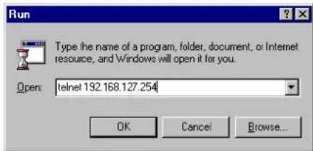
- From the Windows desktop, click Start and then select Run.
- Type telnet 192.168.127.254 (use the correct IP address if different from the default) in the Open text input box, and then click OK.
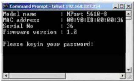
- When the Telnet window opens, if you are prompted to input the Console password, input the password and then press Enter.
Note that this page will only appear if the NPort is password protected.
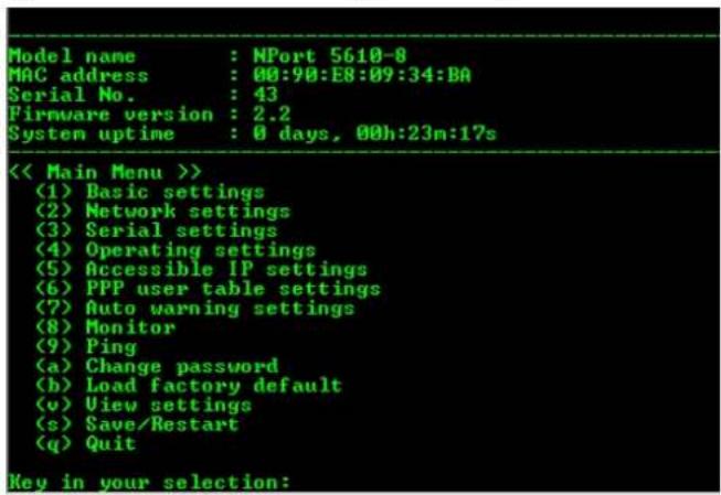
- Type 2 to select Network settings, and then press Enter.
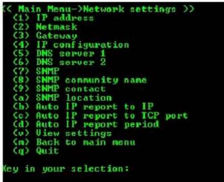
- Type 1 to select IP address and then press Enter.
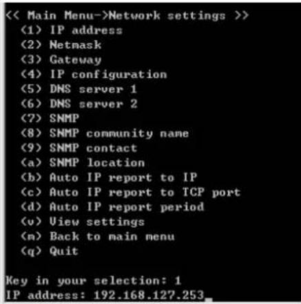
- Use the Backspace key to erase the current IP address, type in the new IP address, and then press Enter.
- Press any key to continue...
<< Main Menu->Network settings >>
(1) IP address
(2) Netmask
(3) Gateway
(4) IP configuration
(5) DNS server 1
(6) DNS server 2
(7) SNMP
(8) SNMP community name
(9) SNMP contact
(a) SNMP location
(b) Auto IP report to IP
(c) Auto IP report to TCP port
(d) Auto IP report period
(v) View settings
(m) Back to main menu
(q) Quit

Key in your selection: 1
IP address: 192.168.127.254
Set IP address success

Press any key to continue...
- Type m or M and then press Enter to return to the main menu.
<< Main Menu->Network settings >>
(1) IP address
(2) Netmask
(3) Gateway
(4) IP configuration
(5) DNS server 1
(6) DNS server 2
(7) SNMP
(8) SNMP community name
(9) SNMP contact
(a) SNMP location
(b) Auto IP report to IP
(c) Auto IP report to TCP port
(d) Auto IP report period
(u) View settings
(n) Back to main menu
(q) Quit

Key in your selection: n
- Type s or S and then press Enter to Save/Restart the system.
Model name : NPort 5610-8
MAC address : 00:90:E8:09:34:DA
Serial No. : 43
Firmware version : 2.2
System uptime : 0 days, 00h:23m:17s

<< Main Menu >>
(1) Basic settings
(2) Network settings
(3) Serial settings
(4) Operating settings
(5) Accessible IP settings
(6) PPP user table settings
(7) Auto warning settings
(8) Monitor
(9) Ping
(a) Change password
(b) Load factory default
(v) View settings
(s) Save/Restart
(q) Quit

Key in your selection:
- Type y or Y and then press Enter to save the new IP address and restart NPort.
Ready to restart
(y) Yes
(n) No
Key in your selection: y.
Choosing the Proper Operation Mode
In this chapter, we describe the various NPort 5600 operation modes. The options include an operation mode that uses a driver installed on the host computer, and operation modes that rely on TCP/IP socket programming concepts. After choosing the proper operation mode in this chapter, refer to Chapter 5 for detailed configuration parameter definitions.
The following topics are covered in this chapter:
Overview
Real COM Mode
TCP Server Mode
TCP Client Mode
□ UDP Mode
□ Pair Connection Mode
□ Reverse Telnet Mode
□ Disabled Mode
□ RFC 2217 Mode
□ PPP Mode
Overview
NPort Device Servers network-enable traditional RS-232/422/485 devices, in which a Device Server is a tiny computer equipped with a CPU, real-time OS, and TCP/IP protocols that can bi-directionally translate data between the serial and Ethernet formats. Your computer can access, manage, and configure remote facilities and equipment over the Internet from anywhere in the world.
Traditional SCADA and data collection systems rely on serial prots (RS-232/422/485) to collect data from various kinds of instruments. Since NPort Serial Device Servers network-enable instruments equipped with an RS-232/422/485 communication port, your SCADA and data collection system will be able to access all instruments connected to a standard TCP/IP network, regardless of whether the devices are used locally or at a remote site.
NPort is an external IP-based network device that allows you to expand the number of serial ports for a host computer on demand. As long as your host computer supports the TCP/IP protocol, you won't be limited by the host computer's bus limitation (such as ISA or PCI), or lack of drivers for various operating systems.
In addition to providing socket access, NPort also comes with a Real COM/TTY driver that transmits all serial signals intact. This means that your existing COM/TTY-based software can be preserved, without needing to invest in additional software.
Three different Socket Modes are available: TCP Server, TCP Client, and UDP Server/Client. The main difference between the TCP and UDP protocols is that TCP guarantees delivery of data by requiring the recipient to send an acknowledgement to the sender. UDP does not require this type of verification, making it possible to offer speedier delivery. UDP also allows multicasting of data to groups of IP addresses.
Real COM Mode
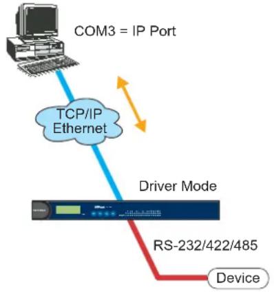
NPort comes equipped with COM drivers that work with Windows 95/98/ME/NT/2000/XP systems, and also TTY drivers for Linux systems. The driver establishes a transparent connection between host and serial device by mapping the IP:Port of the NPort's serial port to a local COM/TTY port on the host computer. This operation mode also supports up to 4 simultaneous connections, so that multiple hosts can collect data from the same serial device at the same time.
Real COM Mode
flowchart
graph TD
    A["COM3 = IP Port"] --> B["TCP/IP Ethernet"]
    B --> C["Driver Mode"]
    C --> D["RS-232/422/485"]
    D --> E["Device"]

ATTENTION
The driver used for Real COM Mode comes with the NPort Windows Administrator. The driver is installed automatically on your computer when you install NPort Administration Suite.
The important point is that Real COM Mode allows users to continue using RS-232/422/485 serial communications software that was written for pure serial communications applications. The driver intercepts data sent to the host's COM port, packs it into a TCP/IP packet, and then redirects it through the host's Ethernet card. At the other end of the connection, the NPort accepts the Ethernet frame, unpacks the TCP/IP packet, and then transparently sends it to the appropriate serial device attached to one of the NPort's serial ports.

ATTENTION
Real COM Mode allows several hosts to have access control over the same NPort. The driver that comes with your NPort controls host access to attached serial devices by checking the host's IP address.
Modify the Accessible IP Setting table when the legal IP address should be required in your application
TCP Server Mode
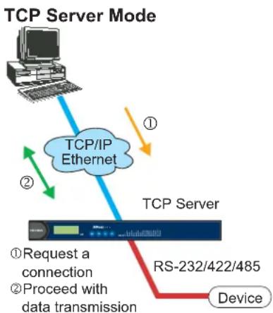
In TCP Server mode, NPort provides a unique IP:Port address on a TCP/IP network. NPort waits passively to be contacted by the host computer, allowing the host computer to establish a connection with and get data from the serial device. This operation mode also supports up to 4 simultaneous connections, so that multiple hosts can collect data from the same serial device—at the same time.
As illustrated in the figure, data transmission proceeds as follows:
- The host requests a connection from the NPort configured for TCP Server Mode.
- Once the connection is established, data can be transmitted in both directions—from the host to the NPort, and from the NPort to the host.
flowchart
graph TD
    A["Computer"] -->|①| B["TCP/IP Ethernet"]
    B --> C["Device"]
    D["RS-232/422/485"] -->|②| E["TCP Server"]
    E --> F["Request a connection"]
    E --> G["Proceed with data transmission"]
TCP Client Mode
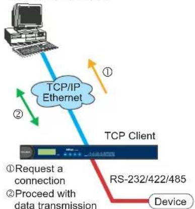
In TCP Client mode, NPort can actively establish a TCP connection to a pre-defined host computer when serial data arrives.
After the data has been transferred, NPort can automatically disconnect from the host computer by using the TCP alive check time or Inactivity time settings. Refer to chapter 5 for more details.
As illustrated in the figure, data transmission proceeds as follows:
- The NPort configured for TCP Client Mode requests a connection from the host.
- Once the connection is established, data can be transmitted in both directions—from the host to the NPort, and from the NPort to the host.
TCP Client Mode
flowchart
graph TD
    A["Computer"] -->|①| B["TCP/IP Ethernet"]
    B --> C["TCP Client"]
    C --> D["RS-232/422/485 Device"]
    C --> E["Request a connection"]
    C --> F["Proceed with data transmission"]
    style A fill:#f9f,stroke:#333
    style B fill:#bbf,stroke:#333
    style C fill:#dfd,stroke:#333
    style D fill:#dfd,stroke:#333
    style E fill:#dfd,stroke:#333
    style F fill:#dfd,stroke:#333
UDP Mode
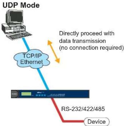
Compared to TCP communication, UDP is faster and more efficient. In UDP mode, you can multicast data from the serial device to multiple host computers, and the serial device can also receive data from multiple host computers, making this mode ideal for message display applications.
flowchart
graph TD
    A["UDP Mode"] --> B["TCP/IP Ethernet"]
    B --> C["RS-232/422/485 Device"]
    D["Directly proceed with data transmission (no connection required)"] --> B
Pair Connection Mode
Pair Connection Mode employs two NPort 5600 in tandem, and can be used to remove the 15-meter distance limitation imposed by the RS-232 interface. One NPort 5600 is connected from its RS-232 port to the COM port of a PC or other type of computer, such as hand-held PDAs that have a serial port, and the serial device is connected to the RS-232 port of the other NPort 5600. The two NPort 5600 units are then connected to each other with a cross-over Ethernet cable, both are connected to the same LAN, or in a more advanced setup, they communicate with each other over a WAN (i.e., through one or more routers). Pair Connection Mode transparently transfers both data and modem control signals (although it cannot transmit the DCD signal) between the two NPorts.
Reverse Telnet Mode
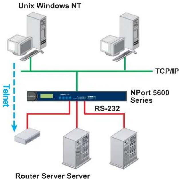
flowchart
graph TD
    A["Unix Windows NT"] --> B["NPort 5600 Series"]
    C["Telnet"] --> B
    D["Router Server Server"] --> B
    B --> E["RS-232"]
    E --> F["Server 1"]
    E --> G["Server 2"]
    E --> H["Server 3"]
    B --> I["TCP/IP"]
Console management is commonly used by connecting to Console/AUX or COM ports of routers, switches, and UPS units. Rtelnet works the same as RAW mode in that only one TCP port is listened to after booting up. The system then waits for a host on the network to initiate a connection. The difference is that the RAW mode does not provide the conversion function provided by Telnet. If the connected devices need to use the CR/LF conversion function when controlling, then users must choose Rtelnet mode.
Disabled Mode
Setting the operation mode of a particular port to Disabled, disables that port.
RFC2217 Mode
RFC2217 is a standard driver that provides Virtual COM function. RFC2217 defines general com port control options based on telnet protocol. Any 3rd party driver supporting RFC2217 can be used to implement virtual COM on NPort 5600 series. The driver establishes a transparent connection between host and serial device by mapping the IP:Port of the NPort 5600 series' serial port to a local COM port on the host computer. (RFC2217 Mode supports 1 connection)
PPP Mode
NPort 5600 Device Server supports standard PPP service for out-of-band management if the Ethernet network crashes. The PPP function enables dial-in access for users who need a remote access solution. When a user at a remote site uses PPP dial-in to connect to NPort 5600, NPort 5600 plays the role of a dial-in server. After the PPP connection is established, the user can remotely manage the NPort 5600.
Please refer to Chapter 5 for detailed information and configuration instructions.
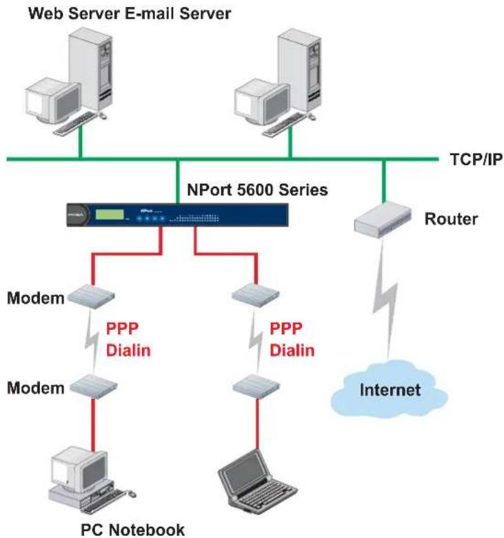
flowchart
graph TD
    A["Web Server E-mail Server"] --> B["NPort 5600 Series"]
    C["TCP/IP"] --> B
    D["Router"] --> B
    B --> E["Modem"]
    B --> F["Modem"]
    B --> G["Modem"]
    B --> H["PC Notebook"]
    B --> I["Internet"]
    B --> J["PPP Dialin"]
    B --> K["PPP Dialin"]
    style B fill:#f9f,stroke:#333
    style E fill:#ccf,stroke:#333
    style F fill:#ccf,stroke:#333
    style G fill:#ccf,stroke:#333
    style H fill:#ccf,stroke:#333
    style I fill:#ccf,stroke:#333
    style J fill:#ccf,stroke:#333
    style K fill:#ccf,stroke:#333
The Web Console is the most user-friendly method available to configure NPort 5600 Series. This chapter will introduce the Web Console function groups and function definitions. The figures in this chapter were borrowed from the manual for NPort 5200, which uses the same Web Console user interface as NPort 5600.
□ Opening Your Browser
□ Basic Settings
□ Network Settings
Serial Settings
□ Operating Settings
Real COM Mode
▶ TCP Server Mode
▶ TCP Client Mode
▶ UDP Mode
▶ Pair Connection Mode
▶ Reverse Telnet Mode
➢ Disabled Mode
➢ RFC 2217 Mode
▶ PPP Mode
□ Accessible IP Settings
□ PPP User Table
□ Auto Warning Settings
▶ Auto warning: E-mail and SNMP Trap
Event Type
Monitor
▶ Monitor Line
▶ Monitor Async
➢ Monitor Async-Settings
□ Change Password
□ Load Factory Default
Opening Your Browser
- Open your browser with the cookie function enabled. (To enable your browser for cookies, right click your desktop Internet Explorer icon, select Properties, click the Security tab, and then select the three Enable options as shown in the figure below.)
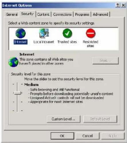
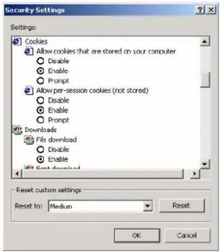
- Type 192.168.127.254 in the Address input box (use the correct IP address if different from the default), and then press Enter.
- Input the password if prompted. The password will be transmitted with MD5 encryption over the Ethernet.
Note that you will not be prompted to enter the password if the NPort is not currently password protected.
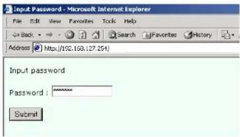

ATTENTION
If you use other web browsers, remember to Enable the functions to "allow cookies that are stored on your computer" or "allow per-session cookies."
NPort 5600 series uses cookies only for "password" transmission.
- The NPort 5600 homepage will open. On this page, you can see a brief description of the Web Console's nine function groups.
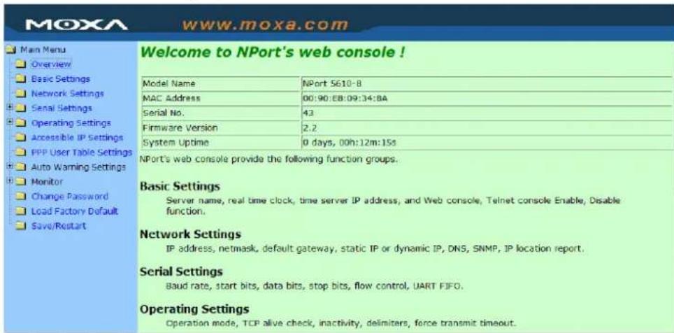

ATTENTION
If you can't remember the password, the ONLY way to start configuring NPort is to load factory defaults by using the Reset button located near the NPort's RJ45 Ethernet port.
Remember to use NPort Administrator to export the configuration file when you have finished the configuration. After using the Reset button to load factory defaults, your configuration can be easily reloaded into NPort by using the NPort Administrator Import function. Refer to Chapter 6 for more details about using the Export and Import functions.

ATTENTION
If your NPort application requires using password protection, you must enable the cookie function in your browser. If the cookie function is disabled, you will not be allowed to enter the Web Console Screen.
Basic Settings
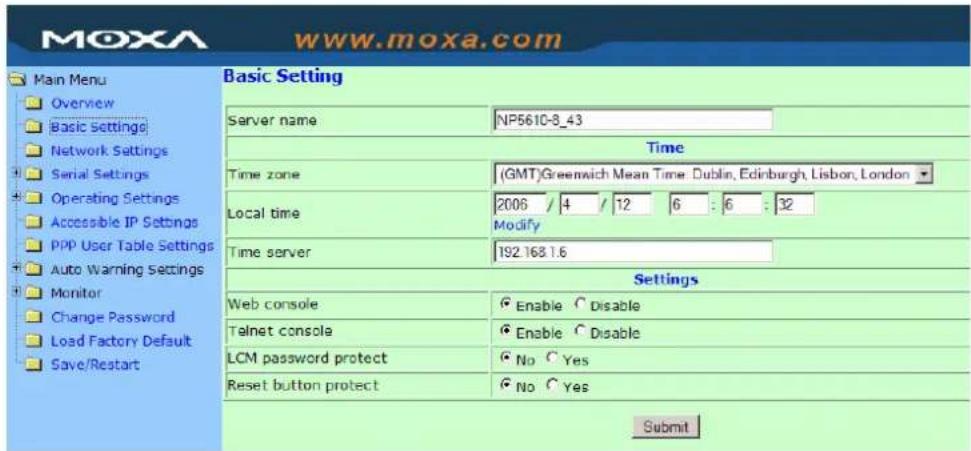
Server name
| Setting Factory Default Necessity | |
| 1 to 39 characters NP[model name]-[Port No.][Serial No.] Optional |
This option is useful for specifying the location or application of different NPorts.
Time
NPort 5600 has a built-in Real-Time Clock for time calibration functions. Functions such as Auto warning "Email" or "SNMP Trap" can add real-time information to the message.

ATTENTION
First time users should select the time zone first. The Console will display the "real time" according to the time zone compared to GMT.
If you would like to modify the real time clock, select "Local time." NPort's firmware will modify the GMT time according to the Time Zone.
Time zone
| Setting Factory Default Necessity | ||
| User selectable time zone GMT (Greenwich Mean Time) Optional |
Local time
| Setting Factory Default Necessity | ||
| User adjustable time.(1900/1/1-2037/12/31) | GMT (Greenwich Mean Time) | Optional |
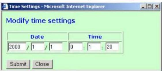
Click the Modify button to open the Modify time settings window to input the correct local time.
Time server
| Setting Factory Default Necessity | ||
| IP or Domain address(E.g., 192.168.1.1 or time.stdtime.gov.tw) | None | Optional |
NPort 5600 uses SNTP (RFC-2030) for auto time calibration.
Input the correct "Time server" IP address or domain address. Once NPort is configured with the correct Time Server address, NPort will request time information from the "Time server" every 10 minutes.
Console
The "Disable" option for Web Console and Telnet Console is included for security reasons. In some cases, you may want to Disable one or both of these Console utilities as an extra precaution to prevent unauthorized users from accessing your NPort. The factory default for both Web Console and Telnet Console is Enable.
| Setting Factory Default Necessity | ||
| Enable or Disable Enable Required |

ATTENTION
If you disable both the "Web Console" and "Telnet Console," you can still use the LCM Display to configure NPort locally, or Windows Administrator to configure NPort either locally or remotely over the network.
Network Settings
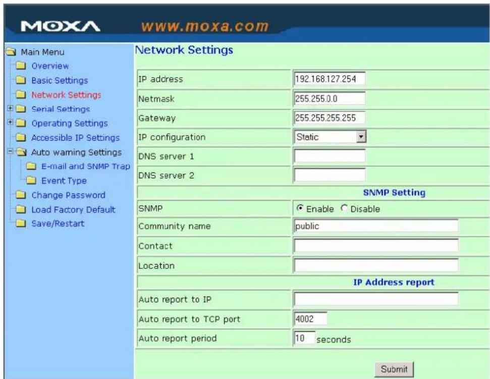
You must assign a valid IP address to NPort 5600 before it will work in your network environment. Your network system administrator should provide you with an IP address and related settings for your network. The IP address must be unique within the network (otherwise, NPort 5600 will not have a valid connection to the network). First time users can refer to Chapter 3, Initial IP Address Configuration, for more information.
You can choose from four possible IP Configuration modes—Static, DHCP, DHCP/BOOTP, and BOOTP located under the web console screen's IP configuration drop-down box.
| Method Function Definition | |
| Static User defined IP address, Netmask, Gateway. | |
| DHCP | DHCP Server assigned IP address, Netmask, Gateway, DNS, and Time Server |
| DHCP/BOOTP | DHCP Server assigned IP address, Netmask, Gateway, DNS, and Time Server, or BOOTP Server assigned IP address (if the DHCP Server does not respond) |
| BOOTP BOOTP | Server assigned IP address |
IP Address
| Setting Factory Default Necessity | ||
| E.g., 192.168.1.1 (IP addresses of the form x.x.x.0 and x.x.x.255 are invalid.) | 192.168.127.254 | Required |
An IP address is a number assigned to a network device (such as a computer) as a permanent address on the network. Computers use the IP address to identify and talk to each other over the network. Choose a proper IP address which is unique and valid in your network environment.
Netmask
| Setting Factory Default Necessity | ||
| E.g., 255.255.255.0 255.255.255.0 Required |
A subnet mask represents all the network hosts at one geographic location, in one building, or on the same local area network. When a packet is sent out over the network, the NPort will use the subnet mask to check if the desired TCP/IP host specified in the packet is on the local network segment. If the address is on the same network segment as the NPort, a connection is established directly from the NPort. Otherwise, the connection is established through the given default gateway.
Gateway
| Setting Factory Default Necessity | ||
| E.g., 192.168.1.1 None Optional |
A gateway is a network gateway that acts as an entrance to another network. Usually, the computers that control traffic within the network or at the local Internet service provider are gateway nodes. NPort needs to know the IP address of the default gateway computer in order to communicate with the hosts outside the local network environment. For correct gateway IP address information, consult the network administrator.
IP Configuration
| Setting Factory Default Necessity | ||
| Static | Static | Required |
| DHCP | ||
| DHCP/BOOTP | ||
| BOOTP |

ATTENTION
In Dynamic IP environments, the firmware will retry 3 times every 30 seconds until network settings are assigned by the DHCP or BOOTP server. The Timeout for each try increases from 1 second, to 3 seconds, to 5 seconds.
If the DHCP/BOOTP Server is unavailable, the firmware will use the default IP address (192.168.127.254), Netmask, and Gateway for IP settings.
DNS server 1 / DNS server 2
| Setting Factory Default Necessity | ||
| E.g., 192.168.1.1(IP addresses of the form x.x.x.0 and x.x.x.255 are invalid.) | None | Optional |
When the user wants to visit a particular website, the computer asks a Domain Name System (DNS) server for the website's correct IP address, and the computer users the response to connect to the web server. DNS is the way that Internet domain names are identified and translated into IP addresses. A domain name is an alphanumeric name, such as moxa.com, that it is usually easier to remember. A DNS server is a host that translates this kind of text-based domain name into the numeric IP address used to establish a TCP/IP connection.
In order to use NPort's DNS feature, you need to set the IP address of the DNS server to be able to access the host with the domain name. NPort provides DNS server 1 and DNS server 2 configuration items to configure the IP address of the DNS server. DNS Server 2 is included for use when DNS sever 1 is unavailable.
NPort plays the role of DNS client. Functions that support domain name in NPort are Time Sever IP Address, TCP Client-Destination IP Address, Mail Server, SNMP Trap IP Address, and IP Location Server.
SNMP Settings
Community name
| Setting Factory Default Necessity | ||
| 1 to 39 characters(E.g., Support, 886-89191230 #300) | public | Optional |
A community name is a plain-text password mechanism that is used to weakly authenticate queries to agents of managed network devices.
Contact
| Setting Factory Default Necessity | ||
| 1 to 39 characters(E.g., Support, 886-89191230 #300) | None | Optional |
The SNMP contact information usually includes an emergency contact name and telephone or pager number.
Location
| Setting Factory Default Necessity | ||
| 1 to 39 characters(E.g., Floor 1, office 2) | None | Optional |
Specify the location string for SNMP agents such as NPort. This string is usually set to the street address where the NPort is physically located.
IP Address Report
When NPort 5600 series products are used in a dynamic IP environment, users must spend more time with IP management tasks. For example, if NPort works as a server (TCP or UDP), then the host, which acts as a client, must know the IP address of the server. If the DHCP server assigns a new IP address to NPort, the host must have some way of determining NPort's new IP address. NPort 5000 series products help out by periodically reporting their IP address to the IP location server, in case the dynamic IP has changed. The parameters shown below are used to configure the Auto IP report function. There are two ways to develop an “Auto IP report Server” to receive NPort's Auto IP report.
- Use NPort Administrator's IP Address Report function.
- “Auto IP report protocol,” which can automatically receive the Auto IP report on a regular basis, is also available to help you develop your own software. Refer to Appendix E for the “Auto IP report protocol”.
Auto report to IP
| Setting Factory Default Necessity | ||
| E.g., 192.168.1.1(IP addresses of the form x.x.x.0 and x.x.x.255 are invalid.) | None | Optional |
Reports generated by the Auto report function will be sent automatically to this IP address.
Auto report to TCP port
| Setting Factory Default Necessity | ||
| E.g., 4001 None Optional |
Auto report period
| Setting Factory Default Necessity | ||
| Time interval (in seconds) 10 Optional |
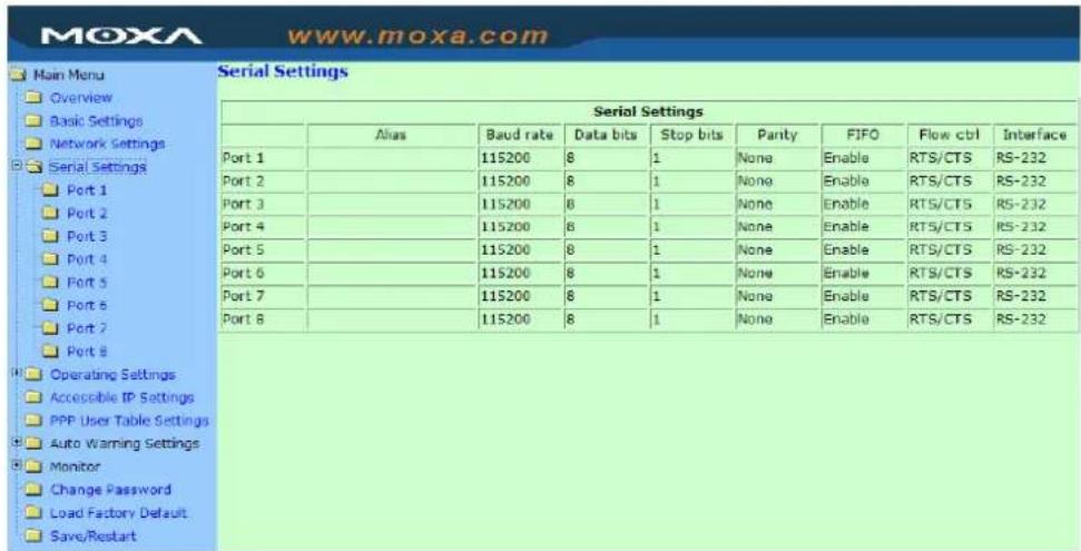
Serial Settings
Click Serial Settings, located under Main Menu, to display serial port settings for ports 1 and 2.
NOTE: Since this figure was borrowed from the manual of NPort 5200, which has only 2 RS-232 ports, there are only 2 ports shown in this figure. Once you have completed the hardware installation of NPort 5600, there should be either 16 or 8 ports shown in the figure, depending on the model you installed. The steps for changing the settings of the other ports are the same as those for Port 1 and Port 2.
To modify serial settings for a particular port, click either Port 1 or Port 2 under Serial Settings, located under Main Menu on the left side of the browser window
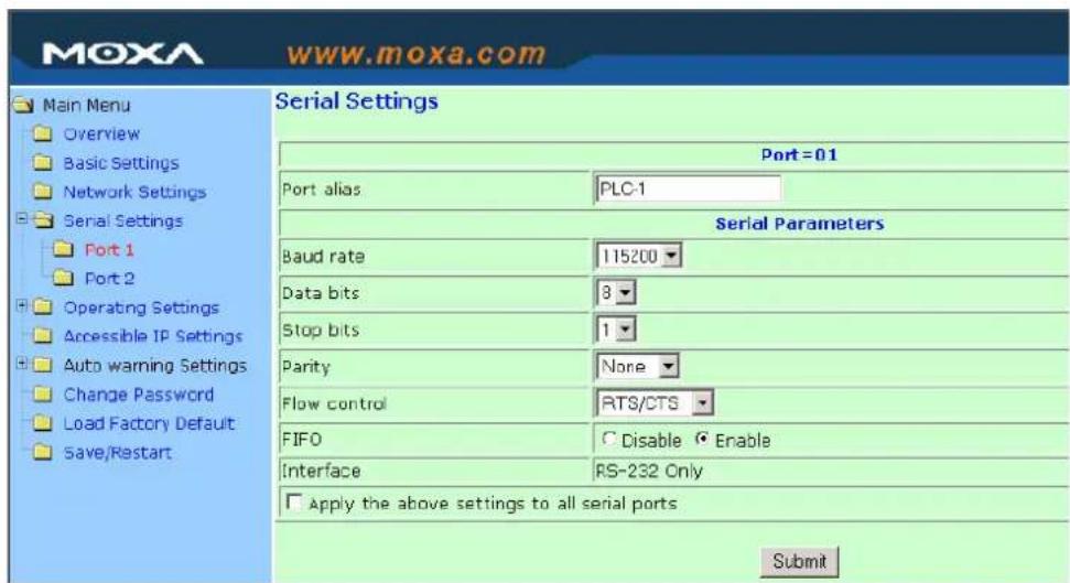
Port alias
| Setting Factory Default Necessity | ||
| 1 to 15 characters(E.g., PLC-No.1) | None | Optional |
"Port Alias" is specially designed to allow easy identification of the serial devices which are connected to NPort's serial port.
Serial Parameters

ATTENTION
Check the serial communication parameters in your Serial Device's user's manual. You should set up NPort's serial parameters with the same communication parameters used by your serial devices.
Baudrate
| Setting Factory Default Necessity | ||
| 50 bps to921.6 Kbps 115.2 Kbps Required |
Data bits
| Setting Factory Default Necessity | ||
| 5, 6, 7, 8 8 Required |
When the user sets Data bits to 5 bits, the stop bits setting will automatically change to 1.5 bits.
Stop bits
| Setting Factory Default Necessity | ||
| 1, 1.5, 2 1 Required |
Stop bits will be set to 1.5 when Data bits is set to 5 bits.
Parity
| Setting Factory Default Necessity | ||
| None, Even, Odd, Space, Mark None Required |
Flow control
| Setting Factory Default Necessity | ||
| None, RTS/CTS, DTR/DSR, Xon/Xoff RTS/CTS Required |
FIFO
| Setting Factory Default Necessity | ||
| Enable, Disable Enable | Required |
NPort's serial ports provide a 16-byte FIFO both in the Tx and Rx directions. Disable the FIFO setting when your serial device does not have a FIFO to prevent data loss during communication.
Interface
| Setting | Factory Default | Necessity |
| NPort 5610-16/8: RS-232 only | RS-232 only | Required |
| NPort 5630-16/8: RS-422/485 only | 4-wire RS-485 | Required |
| NPort 5650-16/8 | RS-232 | Required |
Operating Settings
| Operating Settings | ||||||
| Operating Settings | ||||||
| Port | Operating mode | Packing length | Delimiter 1 | Delimiter 2 | Delimiter process | Force transmit |
| 1 | RFC 2217 Mode | 0 | 0 (Disable) | 0 (Disable) | Do Nothing | 0 |
| TCP alive check time: 7 | ||||||
| 2 | PPP Mode | --- | --- | --- | --- | --- |
| Inactivity time: 0 TCP Compress: No Incoming PAP Check: No Source IP address: Destination IP address: IP netmask: 255.255.255.255 Modem initial string: AT | ||||||
| 3 | PPP Mode | --- | --- | --- | --- | --- |
| Inactivity time: 0 TCP Compress: No Incoming PAP Check: No Source IP address: Destination IP address: IP netmask: 255.255.255.255 Modem initial string: AT | ||||||
| 4 | PPP Mode | --- | --- | --- | --- | --- |
| Inactivity time: 0 TCP Compress: No Incoming PAP Check: No Source IP address: | ||||||
Click Operating Settings located under Main Menu, to display the operating settings for all of NPort's serial ports.
Real COM Mode
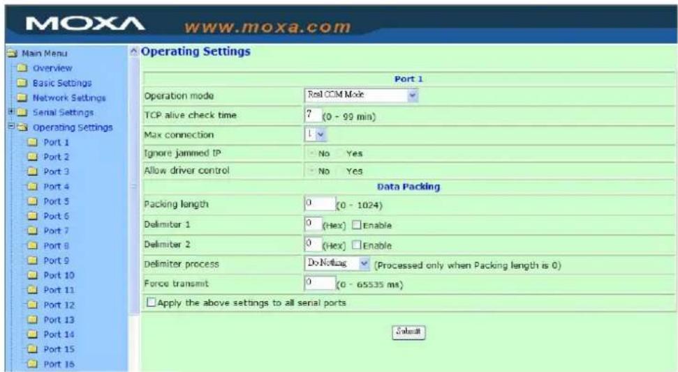
TCP alive check time
| Setting Factory Default Necessity | ||
| 0 to 99 min 7 min Optional |
0 min: TCP connection is not closed due to an idle TCP connection.
1 to 99 min: NPort automatically closes TCP connection if there is no TCP activity for the given time. After the connection is closed, NPort starts listening for another Real COM driver connection from another host.
Max connection
| Setting Factory Default Necessity | ||
| 1, 2, 3, 4 1 Required |
Max connection is usually used when the user needs to receive data from different hosts simultaneously. The factory default is 1. In this case, only one specific host can access this port of the NPort, and the Real COM driver on that host will have full control over the port.
Max. connection 1:
Allows only a single host's Real COM driver to open the specific NPort serial port.
Max connection 2 to 4:
Allows 2 to 4 hosts' Real COM drivers to open the specific NPort serial port at the same time. When multiple hosts' Real COM drivers open the serial port at the same time, the COM driver only provides a pure data tunnel without control ability. That is, this serial port parameter will use firmware's settings, not depend on your application program (AP).
Application software that is based on the COM driver will receive a driver response of “success” when the software uses any of the Win32 API functions. The firmware will only send the data back to the driver on the host.
Data will be sent first-in-first-out when data comes into the NPort from the Ethernet interface.
Ignore jammed IP
| Setting | Factory Default | Necessity |
| No or Yes No Required |
For previous versions of NPort 5200, when Max connections > 1, and the serial device is transmitting data, if any one of the connected hosts was not responding NPort 5200 would wait until the data had been transmitted successfully before transmitting the second group of data to all hosts. For the current version of NPort 5200, if you select Yes for “Ignore jammed IP,” the host that is not responding will be ignored, but the data will still be transmitted to the other hosts.
Allow driver control
| Setting | Factory Default | Necessity |
| No or Yes No Required |
If “max connection” is greater than 1, NPort will ignore driver control commands from all connected hosts. However, if you set “Allow driver control” to YES, control commands will be accepted. Note that since NPort 5200 may get configuration changes from multiple hosts, the most recent command received will take precedence.

ATTENTION
When Max connection is set to 2, 3, or 4, this means that NPort will be using a “multi connection application” (i.e., 2, 3, or 4 hosts are allowed access to the port at the same time). When using a multi connection application, NPort will use the serial communication parameters set in the console. All of the hosts connected to that port must use the same serial settings. If one of the hosts opens the COM port with parameters that are different from NPort’s console setting, data communication may not work properly.
Packing length
| Setting | Factory Default | Necessity |
| 0 to 1024 0 Required |
Default = 0, The Delimiter Process will be followed, regardless of the length of the data packet. If the data length (in bytes) matches the configured value, the data will be forced out. The data length can be configured for 0 to 1024 bytes. Set to 0 if you do not need to limit the length.
Delimiter 1
| Setting Factory Default Necessity | ||
| 00 to FF None Optional |
Delimiter 2
| Setting Factory Default Necessity | ||
| 00 to FF None Optional |
Once the NPort receives both delimiters through its serial port, it immediately packs all data currently in its buffer and sends it to the NPort's Ethernet port.

ATTENTION
Delimiter 2 is optional. If left blank, then Delimiter 1 alone trips clearing of the buffer. If the size of the serial data received is greater than 1 KB, the NPort will automatically pack the data and send it to the Ethernet. However, to use the delimiter function, you must at least enable Delimiter 1. If Delimiter 1 is left blank and Delimiter 2 is enabled, the delimiter function will not work properly.
Delimiter process
| Setting | Factory Default | Necessity |
| Do nothing, Delimiter + 1, Delimiter + 2, Strip Delimiter | Do Nothing Required |
When [Delimiter + 1] or [Delimiter + 2] is selected, the data will be transmitted when an additional byte (for Delimiter + 1), or an additional 2 bytes (for Delimiter + 2) of data is received after receiving the Delimiter.
When [Strip Delimiter] is selected, when the Delimiter is received, the Delimiter is deleted (i.e., stripped), and the remaining data is transmitted.
When [Do nothing] is selected, the data will be transmitted when the Delimiter is received.
Force transmit
| Setting Factory Default Necessity | ||
| 0 to 65535 ms 0 ms Optional |
0: Disable the force transmit timeout.
1 to 65535: Forces the NPort's TCP/IP protocol software to try to pack serial data received during the specified time into the same data frame.
This parameter defines the time interval during which NPort fetches the serial data from its internal buffer. If data is incoming through the serial port, NPort stores the data in the internal buffer. NPort transmits data stored in the buffer via TCP/IP, but only if the internal buffer is full or if the Force transmit time interval reaches the time specified under Force transmit timeout.
The optimal Force transmit timeout depends on your application, but it must be at least larger than one character interval within the specified baudrate. For example, assume that the serial port is set to 1200 bps, 8 data bits, 1 stop bit, and none for parity. In this case, the total number of bits needed to send a character is 10 bits, and the time required to transfer one character is
(10(bits)/1200(bits/s)*1000(ms/s)=8.3ms.
Therefore, you should set Force transmit timeout to be larger than 8.3 ms, so in this case, it must be greater than or equal to 10 ms.
If the user wants to send the series of characters in the same packet, the serial device attached to NPort should send that series of characters during a time interval less than the Force Transmit timeout for NPort, and the total length of data must be less than or equal to NPort's internal buffer size. The serial communication buffer size for NPort is 1 KB per port.
TCP Server Mode
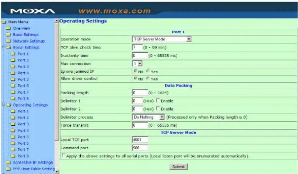
TCP alive check time
| Setting Factory Default Necessity | ||
| 0 to 99 min 7 min Optional |
0 min: TCP connection is not closed due to an idle TCP connection.
1 to 99 min: NPort automatically closes the TCP connection if there is no TCP activity for the given time. After the connection is closed, NPort starts listening for another host's TCP connection.
Inactivity time
| Setting Factory Default Necessity | ||
| 0 to 65535 ms 0 ms Optional |
0 ms: TCP connection is not closed due to an idle serial line.
0-65535 ms: NPort automatically closes the TCP connection if there is no serial data activity for the given time. After the connection is closed, NPort starts listening for another host's TCP connection.
This parameter defines the maintenances status as Closed or Listen on the TCP connection. The connection is closed if there is no incoming or outgoing data through the serial port during the specific Inactivity time.
If the Inactivity time is set to 0, the current TCP connection is kept active until a connection close request is received. Although Inactivity time is disabled, the NPort will check the connection status between the NPort and remote host by sending “keep alive” packets periodically. If the remote host does not respond to the packet, NPort assumes that the connection was closed down unintentionally. NPort will then force the existing TCP connection to close.

ATTENTION
The Inactivity time should at least be set larger than that of Force transmit timeout. To prevent the unintended loss of data due to the session being disconnected, it is highly recommended that this value is set large enough so that the intended data transfer is completed.
Max connection
| Setting Factory Default Necessity | ||
| 1, 2, 3, 4 1 Required |
Max connection is usually used when the user needs to receive data from different hosts simultaneously. The factory default only allows 1 connection at a time.
Max. connection 1:
NPort only allows 1 host to open the TCP connection to the specific serial port.
Max connection 2 to 4:
Allows 2 to 4 host's TCP connection request to open this NPort serial port, at the same time. When multiple hosts establish a TCP connection to the specific serial port at the same time, NPort will duplicate the serial data and transmit to all of the hosts. Ethernet data is sent on a first-in-first-out basis to the serial port when data comes into NPort from the Ethernet interface.
Ignore jammed IP
| Setting | Factory Default | Necessity |
| No or Yes No Required |
For previous versions of NPort 5200, when Max connections > 1, and the serial device is transmitting data, if any one of the connected hosts was not responding NPort 5200 would wait until the data had been transmitted successfully before transmitting the second group of data to all hosts. For the current version of NPort 5200, if you select Yes for “Ignore jammed IP,” the host that is not responding will be ignored, but the data will still be transmitted to the other hosts.
Allow driver control
| Setting | Factory Default | Necessity |
| No or Yes No Required |
If “max connection” is greater than 1, NPort will ignore driver control commands from all connected hosts. However, if you set “Allow driver control” to YES, control commands will be accepted. Note that since NPort 5200 may get configuration changes from multiple hosts, the most recent command received will take precedence.
Packing length
| Setting | Factory Default | Necessity |
| 0 to 1024 0 Required |
Default = 0, The Delimiter Process will be followed, regardless of the length of the data packet. If the data length (in bytes) matches the configured value, the data will be forced out. The data length can be configured for 0 to 1024 bytes. Set to 0 if you do not need to limit the length.
Delimiter 1
| Setting Factory Default Necessity | ||
| 00 to FF None Optional |
Delimiter 2
| Setting Factory Default Necessity | ||
| 00 to FF None Optional |
Once the NPort receives both delimiters through its serial port, it immediately packs all data currently in its buffer and sends it to the NPort's Ethernet port.
Delimiter process
| Setting | Factory Default | Necessity |
| Do nothing, Delimiter + 1, Delimiter + 2, Strip Delimiter | Do Nothing | Required |
When [Delimiter + 1] or [Delimiter + 2] is selected, the data will be transmitted when an additional byte (for Delimiter + 1), or an additional 2 bytes (for Delimiter + 2) of data is received after receiving the Delimiter. When [Strip Delimiter] is selected, when the Delimiter is received, the Delimiter is deleted (i.e., stripped), and the remaining data is transmitted. When [Do nothing] is selected, the data will be transmitted when the Delimiter is received.

ATTENTION
Delimiter 2 is optional. If left blank, then Delimiter 1 alone trips clearing of the buffer. If the size of the serial data received is greater than 1 KB, the NPort will automatically pack the data and send it to the Ethernet. However, to use the delimiter function, you must at least enable Delimiter 1. If Delimiter 1 is left blank and Delimiter 2 is enabled, the delimiter function will not work properly.
Force transmit
| Setting Factory Default Necessity | ||
| 0 to 65535 ms 0 ms Optional |
0: Disable the force transmit timeout.
1 to 65535: Forces the NPort's TCP/IP protocol software to try to pack serial data received during the specified time into the same data frame.
This parameter defines the time interval during which NPort fetches the serial data from its internal buffer. If data is incoming through the serial port, NPort stores the data in the internal buffer. NPort transmits data stored in the buffer via TCP/IP, but only if the internal buffer is full or if the Force transmit time interval reaches the time specified under Force transmit timeout.
The optimal Force transmit timeout depends on your application, but it must be at least larger than one character interval within the specified baudrate. For example, assume that the serial port is set to 1200 bps, 8 data bits, 1 stop bit, and none for parity. In this case, the total number of bits needed to send a character is 10 bits, and the time required to transfer one character is
(10(bits)/1200(bits/s) * 1000(ms/s) = 8.3 ms.
Therefore, you should set Force transmit timeout to be larger than 8.3 ms, so in this case, it must be greater than or equal to 10 ms.
If the user wants to send the series of characters in the same packet, the serial device attached to NPort should send that series of characters during a time interval less than the Force Transmit timeout for NPort, and the total length of data must be less than or equal to NPort's internal buffer size. The serial communication buffer size for NPort is 1 KB per port.
Local TCP port
| Setting Factory Default Necessity | ||
| 1 to 65535 4001 Required |
The “Local TCP port” is the TCP port that NPort uses to listen to connections, and that other devices must use to contact NPort. To avoid conflicts with well known TCP ports, the default is set to 4001.
Command port
| Setting Factory Default Necessity | ||
| 1 to 65535 966 Optional |
The “Command port” is a listen TCP port for IP-Serial Lib commands from the host. In order to prevent a TCP port conflict with other applications, the user can set the Command port to another port if needed. IP-Serial Lib will automatically check the Command Port on NPort so that the user does not need to configure the program.
TCP Client Mode
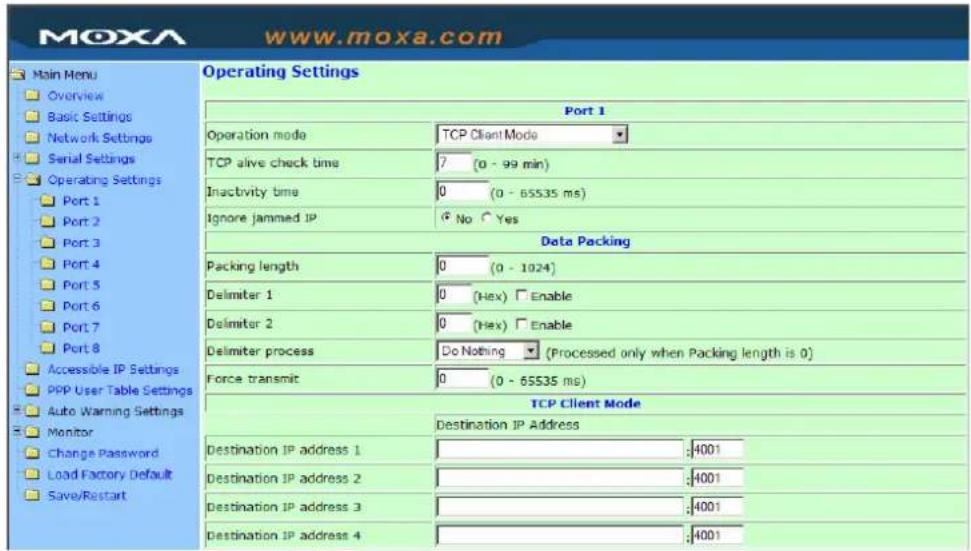
TCP alive check time
| Setting Factory Default Necessity | ||
| 0 to 99 min 7 min Optional |
0 min: TCP connection is not closed due to an idle TCP connection.
1 to 99 min: NPort automatically closes the TCP connection if there is no TCP activity for the given time.
Inactivity time
| Setting Factory Default Necessity | ||
| 0 to 65535 ms 0 ms Optional |
0 ms: TCP connection is not closed due to an idle serial line.
0-65535 ms: NPort automatically closes TCP connection, if there is no serial data activity for the given time.
This parameter defines the maintenances status as Closed or Listen on the TCP connection. The connection is closed if there is no incoming or outgoing data through the serial port during the specific Inactivity time.
If the value of inactivity time is set to 0, the current TCP connection is maintained unless there's no connection close request. Although the inactivity time is disabled, the NPort will check the connection status between the NPort and remote host by sending "keep alive" packets periodically. If the remote host does not respond to the packets, it treats the connection as being down unintentionally. NPort will then force the existing TCP connection to close.

ATTENTION
The Inactivity time should at least be set larger than that of Force transmit timeout. To prevent the unintended loss of data due to the session being disconnected, it is highly recommended that this value is set large enough so that the intended data transfer is completed.

ATTENTION
Inactivity time is ONLY active when “TCP connect on” is set to “Any character.”
Ignore jammed IP
| Setting | Factory Default | Necessity |
| No or Yes No Required |
For previous versions of NPort 5200, when Max connections > 1, and the serial device is transmitting data, if any one of the connected hosts was not responding NPort 5200 would wait until the data had been transmitted successfully before transmitting the second group of data to all hosts. For the current version of NPort 5200, if you select Yes for “Ignore jammed IP,” the host that is not responding will be ignored, but the data will still be transmitted to the other hosts.
Allow driver control
| Setting | Factory Default | Necessity |
| No or Yes No Required |
If “max connection” is greater than 1, NPort will ignore driver control commands from all connected hosts. However, if you set “Allow driver control” to YES, control commands will be accepted. Note that since NPort 5200 may get configuration changes from multiple hosts, the most recent command received will take precedence.
Packing length
| Setting | Factory Default | Necessity |
| 0 to 1024 0 Required |
Default = 0, The Delimiter Process will be followed, regardless of the length of the data packet. If the data length (in bytes) matches the configured value, the data will be forced out. The data length can be configured for 0 to 1024 bytes. Set to 0 if you do not need to limit the length.
Delimiter 1
| Setting Factory Default Necessity | ||
| 00 to FF None Optional |
Delimiter 2
| Setting Factory Default Necessity | ||
| 00 to FF None Optional |
Once the NPort receives both delimiters through its serial port, it immediately packs all data currently in its buffer and sends it to the NPort's Ethernet port.

ATTENTION
Delimiter 2 is optional. If left blank, then Delimiter 1 alone trips clearing of the buffer. If the size of the serial data received is greater than 1 KB, the Nport will automatically pack the data and send it to the Ethernet. However, to use the delimiter function, you must at least enable Delimiter 1. If Delimiter 1 is left blank and Delimiter 2 is enabled, the delimiter function will not work properly.
Delimiter process
| Setting | Factory Default | Necessity |
| Do nothing, Delimiter + 1, Delimiter + 2, Strip Delimiter | Do Nothing Required |
When [Delimiter + 1] or [Delimiter + 2] is selected, the data will be transmitted when an additional byte (for Delimiter +1), or an additional 2 bytes (for Delimiter +2) of data is received after receiving the Delimiter.
When [Strip Delimiter] is selected, when the Delimiter is received, the Delimiter is deleted (i.e., stripped), and the remaining data is transmitted.
When [Do nothing] is selected, the data will be transmitted when the Delimiter is received.
Force transmit
| Setting Factory Default Necessity | ||
| 0 to 65535 ms 0 ms Optional |
0: Disable the force transmit timeout.
1 to 65535: Forces the NPort's TCP/IP protocol software to try to pack serial data received during the specified time into the same data frame.
This parameter defines the time interval during which NPort fetches the serial data from its internal buffer. If data is incoming through the serial port, NPort stores the data in the internal buffer. NPort transmits data stored in the buffer via TCP/IP, but only if the internal buffer is full or if the Force transmit time interval reaches the time specified under Force transmit timeout.
The optimal Force transmit timeout depends on your application, but it must be at least larger than one character interval within the specified baudrate. For example, assume that the serial port is set to 1200 bps, 8 data bits, 1 stop bit, and none for parity. In this case, the total number of bits needed to send a character is 10 bits, and the time required to transfer one character is
(10 (bits) / 1200 (bits/s)) * 1000 (ms/s) = 8.3 ms.
Therefore, you should set Force transmit timeout to be larger than 8.3 ms, so in this case, it must be greater than or equal to 10 ms.
If the user wants to send the series of characters in the same packet, the serial device attached to NPort should send that series of characters during a time interval less than the Force Transmit timeout for NPort, and the total length of data must be less than or equal to NPort's internal buffer size. The serial communication buffer size for NPort is 1 KB per port.
Destination IP address 1
| Setting Factory Default Necessity | ||
| IP address or Domain Address(E.g., 192.168.1.1) | None | Required |
Allows NPort to connect actively to the remote host whose address is set by this parameter.
Destination IP address 2/3/4
| Setting Factory Default Necessity | ||
| IP address or Domain Address(E.g., 192.168.1.1) | None | Optional |
Allows NPort to connect actively to the remote host whose address is set by this parameter.
Designated Local Port 1/2/3/4
| Setting | Factory Default | Necessity |
| TCP Port No. | 5011(Port 1) 5012(Port 2)5013(Port 3) 5014(Port 4) | Required |
Connection control
| Setting | Factory Default | Necessity |
| Startup/None,Any Character/None,Any Character/Inactivity Time,DSR ON/DSR OFF,DSR ON/None,DCD ON/DCD OFF,DCD ON/None | Startup/None | Required |
The meaning of each of the above settings is given in the table below. In general, both the Connect condition and Disconnect condition are given.
| Connect/Disconnect | Description |
| Startup/None (default) | A TCP connection will be established on startup, and will remain active indefinitely. |
| Any Character/None | A TCP connection will be established when any character is received from the serial interface, and will remain active indefinitely. |
| Any Character/ Inactivity Time | A TCP connection will be established when any character is received from the serial interface, and will be disconnected when the Inactivity time out is reached. |
| DSR On/DSR Off | A TCP connection will be established when a DSR “On” signal is received, and will be disconnected when a DSR “Off” signal is received. |
| DSR On/None | A TCP connection will be established when a DSR “On” signal is received, and will remain active indefinitely. |
| DCD On/DCD Off | A TCP connection will be established when a DCD “On” signal is received, and will be disconnected when a DCD “Off” signal is received. |
| DCD On/None | A TCP connection will be established when a DCD “On” signal is received, and will remain active indefinitely. |

ATTENTION
Up to 4 connections can be established between NPort and hosts. The connection speed or throughput may be low if one of the four connections is slow, since the 1 slow connection will slow down the other 3 connections.

ATTENTION
The “Destination IP address” parameter can use both IP address and Domain Name. For some applications, the user may need to send the data actively to the remote destination domain name.
UDP Mode
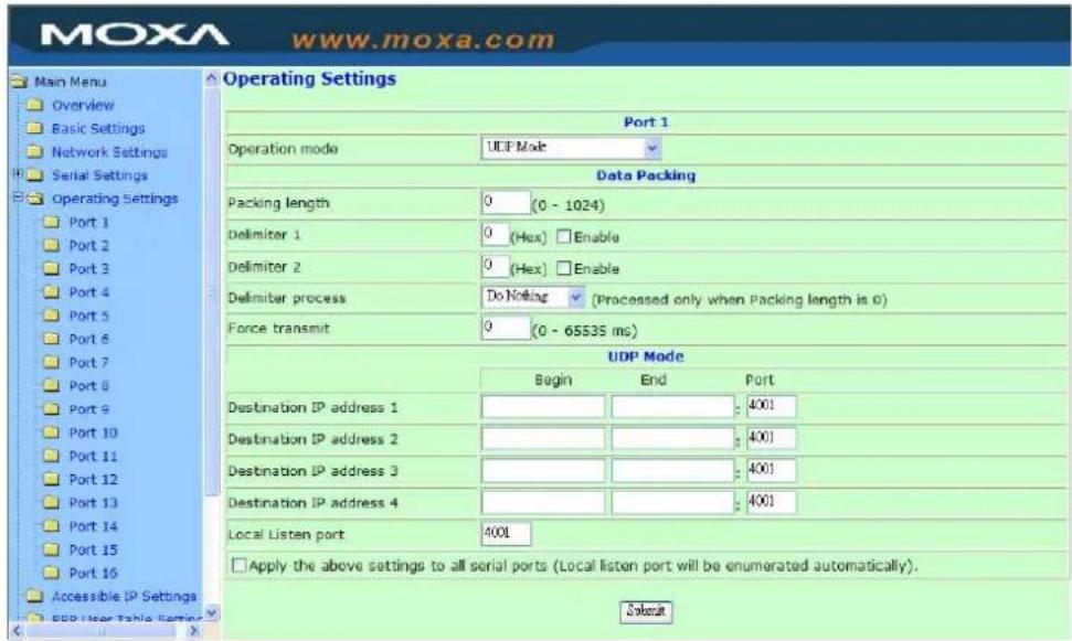
Packing length
| Setting | Factory Default | Necessity |
| 0 to 1024 0 Required |
Default = 0, The Delimiter Process will be followed, regardless of the length of the data packet. If the data length (in bytes) matches the configured value, the data will be forced out. The data length can be configured for 0 to 1024 bytes. Set to 0 if you do not need to limit the length.
Delimiter 1
| Setting Factory Default Necessity | ||
| 00 to FF None Optional |
Delimiter 2
| Setting Factory Default Necessity | ||
| 00 to FF None Optional |
Once the NPort receives both delimiters through its serial port, it immediately packs all data currently in its buffer and sends it to the NPort's Ethernet port.
Delimiter process
| Setting | Factory Default | Necessity |
| Do nothing, Delimiter + 1, Delimiter + 2, Strip Delimiter | Do Nothing Required |
When [Delimiter + 1] or [Delimiter + 2] is selected, the data will be transmitted when an additional byte (for Delimiter + 1), or an additional 2 bytes (for Delimiter + 2) of data is received after receiving the Delimiter.
When [Strip Delimiter] is selected, when the Delimiter is received, the Delimiter is deleted (i.e., stripped), and the remaining data is transmitted.
When [Do nothing] is selected, the data will be transmitted when the Delimiter is received.

ATTENTION
Delimiter 2 is optional. If left blank, then Delimiter 1 alone trips clearing of the buffer. If the size of the serial data received is greater than 1 KB, the NPort will automatically pack the data and send it to the Ethernet. However, to use the delimiter function, you must at least enable Delimiter 1. If Delimiter 1 is left blank and Delimiter 2 is enabled, the delimiter function will not work properly.
Force transmit
| Setting Factory Default Necessity | ||
| 0 to 65535 ms 0 ms Optional |
0: Disable the force transmit timeout.
1 to 65535: Forces the NPort's TCP/IP protocol software to try to pack serial data received during the specified time into the same data frame.
This parameter defines the time interval during which NPort fetches the serial data from its internal buffer. If data is incoming through the serial port, NPort stores the data in the internal buffer. NPort transmits data stored in the buffer via TCP/IP, but only if the internal buffer is full or if the Force transmit time interval reaches the time specified under Force transmit timeout.
The optimal Force transmit timeout depends on your application, but it must be at least larger than one character interval within the specified baudrate. For example, assume that the serial port is set to 1200 bps, 8 data bits, 1 stop bit, and none for parity. In this case, the total number of bits needed to send a character is 10 bits, and the time required to transfer one character is
(10 (bits) / 1200 (bits/s)) * 1000 (ms/s) = 8.3 ms.
Therefore, you should set Force transmit timeout to be larger than 8.3 ms, so in this case, it must be greater than or equal to 10 ms.
If the user wants to send the series of characters in the same packet, the serial device attached to NPort should send that series of characters during a time interval less than the Force Transmit timeout for NPort, and the total length of data must be less than or equal to NPort's internal buffer size. The serial communication buffer size for NPort is 1 KB per port.
Destination IP address 1
| Setting Factory Default Necessity | ||
| IP address rangeE.g., Begin: 192.168.1.1End: 192.168.1.10 | Begin: Empty | Required |
| End: Empty | ||
| Port: 4001 |
Destination IP address 2/3/4
| Setting Factory Default Necessity | ||
| IP address rangeE.g., Begin: 192.168.1.11End: 192.168.1.20 | Begin: Empty | Optional |
| End: Empty | ||
| Port: 4001 |
Local listen port
| Setting Factory Default Necessity | ||
| 1 to 65535 4001 Required |
The UDP port that NPort listens to, and that other devices must use to contact NPort. To avoid conflicts with well known UDP ports, the default is set to 4001.
Pair Connection Mode
Pair Connection Mode employs two NPort 5600 device servers in tandem, and can be used to remove the 15-meter distance limitation imposed by the RS-232 interface. One NPort 5600 is connected from its RS-232 port to the COM port of a PC or other type of computer, such as hand-held PDAs that have a serial port, and the serial device is connected to the RS-232 port of the other NPort 5600. The two NPort 5600 device servers are then connected to each other with a cross-over Ethernet cable, both are connected to the same LAN, or in a more advanced setup, they communicate with each other over a WAN (i.e., through one or more routers). Pair Connection Mode transparently transfers both data and modem control signals (although it cannot transmit the DCD signal) between the two NPorts.
Pair Connection Master Mode
When using Pair Connection Mode, you must select Pair Connection Master Mode for the Operation mode of one of the NPort 5600 device servers. In effect, this NPort 5600 will be acting as a TCP client.
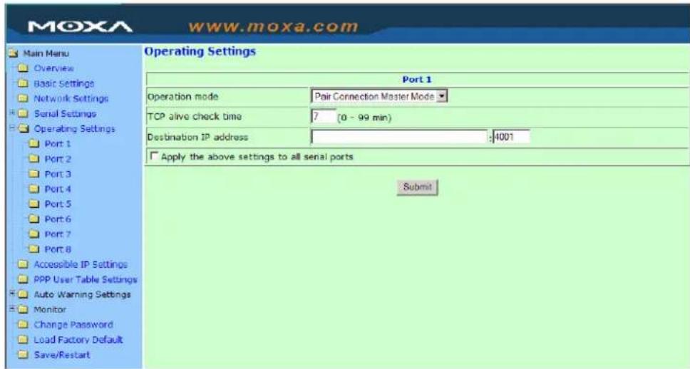
TCP alive check time
| Setting Factory Default Necessity | ||
| 0 to 99 min | 7 min | Required |
0 min: TCP connection is not closed due to an idle TCP connection.
1 to 99 min: NPort 5600 closes the TCP connection automatically if there is no TCP activity for the given time.
Destination IP address
| Setting Factory Default Necessity | ||
| IP address or Domain Name(E.g., 192.168.1.1) | blank | Optional |
| TCP port No. 4001 Required |
The Pair Connection “Master” will contact the network host that has this IP address. Data will be transmitted through the port No. (4001 by default). Note that you must configure the same TCP port No. for the device server acting as the Pair Connection “Slave.”
Pair Connection Slave Mode
When using Pair Connection Mode, you must select Pair Connection Slave Mode for the Operation mode of one of the NPort 5600 device servers. In effect, this NPort 5600 will be acting as a TCP server.
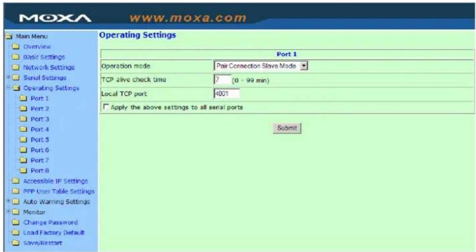
TCP alive check time
| Setting Factory Default Necessity | ||
| 0 to 99 min | 7 min | Required |
0 min: TCP connection is not closed due to an idle TCP connection.
1 to 99 min: NPort 5600 closes the TCP connection automatically if there is no TCP activity for the given time.
Local TCP port
| Setting Factory Default Necessity | ||
| TCP port No. (e.g., 4001) | 4001 | Required |
This Port No. must be the same port No. that you set up for the Pair Connection "Master" device server.
Reverse Telnet Mode
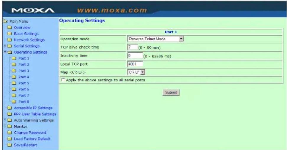
TCP alive check time
| Setting Factory Default Necessity | ||
| 0 to 99 min 0 Optional |
Specifies the time slice for checking if the TCP connection is alive. If there is no response, NPort 5600 series will disconnect the original connection.
Inactivity time
| Setting Factory Default Necessity | ||
| 0 to 65535 ms 0 Optional |
Idle time setting for auto-disconnection. 0 min. means it will never disconnect.
Local TCP port
| Setting Factory Default Necessity | ||
| 1 to 65535 4001 Optional |
Each of NPort's serial ports is mapped to a TCP port. To avoid conflicts with TCP ports, set port numbers to 4001 for port1, 4002 for port 2, etc. (like the default values).
Map
| Setting Factory Default Necessity | ||
| CR, LF, or CR-LF CR-LF Optional |
If data received through NPort 5600's Ethernet port is sent using the "enter" command, the data will be transmitted out the serial port with an added
-
“carriage return + line feed” if you select the
option (i.e., the cursor will jump to the next line, and return to the first character of the line) -
“carriage return” if you select the
option (i.e., the cursor will return to the first character of the line) -
"line feed" if you select the
option. (i.e., the cursor will jump to the next line, but not mov horizontally)
Disabled Mode
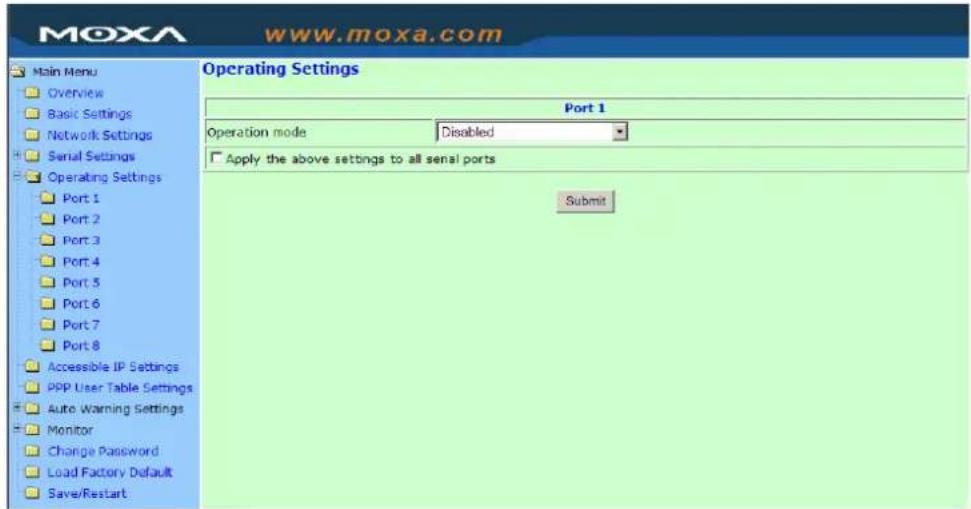
When Operation mode is set to Disabled, that particular port will be disabled. Select the Apply the above settings to all serial ports option to apply this setting to the other ports.
RFC2217 Mode
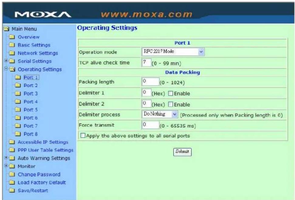
TCP alive check time
| Setting Factory Default Necessity | ||
| 0 to 99 min 7 min Optional |
0 min: TCP connection is not closed due to an idle TCP connection.
1 to 99 min: NPort 5600 automatically closes the TCP connection if there is no TCP activity for the given time. After the connection is closed, NPort 5600 starts listening for another Real COM driver connection from another host.
Packing length
| Setting Factory Default Necessity | ||
| 0 to 1024 0 Optional |
Default = 0, The Delimiter Process will be followed, regardless of the length of the data packet. If the data length (in bytes) matches the configured value, the data will be forced out. The data length can be configured for 0 to 1024 bytes. Set to 0 if you do not need to limit the length.
Delimiter 1
| Setting Factory Default Necessity | ||
| 00 to FF (hex) None Optional |
Delimiter 2
| Setting Factory Default Necessity | ||
| 00 to FF (hex) None Optional |
Once the NPort 5600 receives both delimiters through its serial port, it immediately packs all data currently in its buffer and sends it to the NPort 5600's Ethernet port.

ATTENTION
Delimiter 2 is optional. If left blank, then Delimiter 1 alone trips clearing of the buffer. If the size of the serial data received is greater than 1 KB, the NPort 5600 will automatically pack the data and send it to the Ethernet. However, to use the delimiter function, you must at least enable Delimiter 1. If Delimiter 1 is left blank and Delimiter 2 is enabled, the delimiter function will not work properly.
Delimiter process
| Setting Factory Default Necessity | ||
| Do nothingDelimiter + 1Delimiter + 2Strip Delimiter | Do Nothing Optional |
[Delimiter + 1] or [Delimiter + 2]: The data will be transmitted when an additional byte (for Delimiter + 1), or an additional 2 bytes (for Delimiter + 2) of data is received after receiving the Delimiter.
[Strip Delimiter]: When the Delimiter is received, the Delimiter is deleted (i.e., stripped), and the remaining data is transmitted.
[Do nothing]: The data will be transmitted when the Delimiter is received.
Force transmit
| Setting Factory Default Necessity | ||
| 0 to 65535 ms 0 ms Optional |
0: Disable the force transmit timeout.
1 to 65535: Forces the NPort 5600's TCP/IP protocol software to try to pack serial data received during the specified time into the same data frame.
This parameter defines the time interval during which NPort 5600 fetches the serial data from its internal buffer. If data is incoming through the serial port, NPort 5600 stores the data in the internal buffer. NPort 5600 transmits data stored in the buffer via TCP/IP, but only if the internal buffer is full or if the Force transmit time interval reaches the time specified under Force transmit timeout.
The optimal Force transmit timeout depends on your application, but it must be at least larger than one character interval within the specified baudrate. For example, assume that the serial port is set to 1200 bps, 8 data bits, 1 stop bit, and no parity. In this case, the total number of bits needed to send a character is 10 bits, and the time required to transfer one character is
(10(bits)/1200(bits/s)*1000(ms/s)=8.3ms.
Therefore, you should set Force transmit timeout to be larger than 8.3 ms, so in this case, it must be greater than or equal to 10 ms.
If the user wants to send a series of characters in the same packet, the serial device attached to NPort 5600 should send that series of characters during a time interval less than the Force transmit timeout for NPort 5600, and the total length of data must be less than or equal to NPort 5600's internal buffer size. The serial communication buffer size for NPort 5600 is 1 KB per port.
PPP Mode
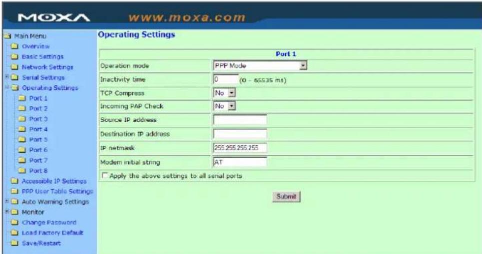
PPP provides standard PPP service for dial-in.
Inactivity time
| Setting Factory Default Necessity | ||
| 0 to 65535 ms 0 Optional |
Idle time setting for auto-disconnection. 0 min. means it will never disconnect.
TCP/IP compression
| Setting Factory Default Necessity | ||
| Yes or No No Optional |
Depends on whether the remote user's application requests compression.
Incoming PAP check
| Setting Factory Default Necessity | ||
| Yes or No No Optional |
Depends on whether the remote user's application requests PAP check.
Source IP address
| Setting Factory Default Necessity | ||
| Source IP address Required |
Destination IP address
| Setting Factory Default Necessity | ||
| Destination IP address Required |
Designation IP address is IP address of remote dial-in server.
IP netmask
| Setting Factory Default Necessity | ||
| IP netmask Optional |
NPort 5600 automatically assigns the netmask 255.255.255.255. We recommend leaving this space blank.
Modem Initial stream
| Setting Factory Default Necessity | ||
| Modem Initial stream | AT | Optional |
Accessible IP Settings
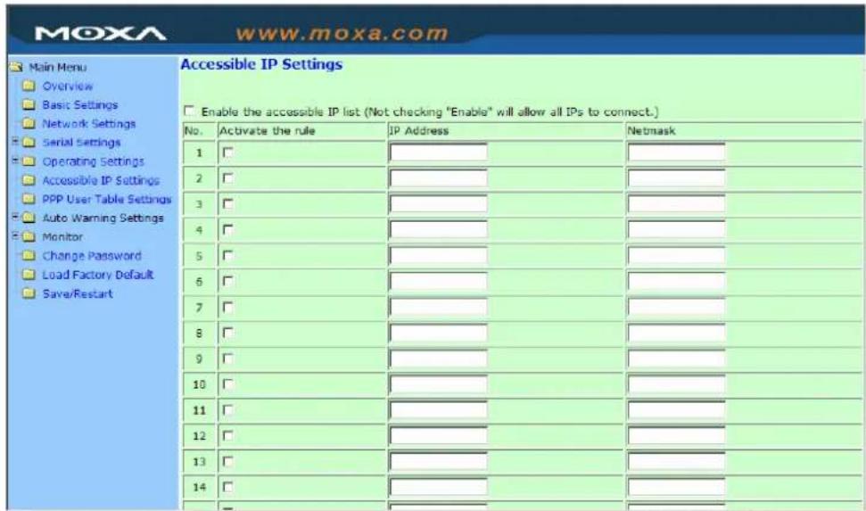
NPort has an IP address based filtering method to control access to itself.
Accessible IP Settings allows you to add or block remote host IP addresses to prevent unauthorized access. Access to NPort is controlled by IP address. That is, if a host's IP address is in the accessible IP table, then the host will be allowed to access the NPort. You can allow one of the following cases by setting the parameter.
• Only one host with a specific IP address can access the NPort
Enter "IP address/255.255.255.255" (e.g., "192.168.1.1/255.255.255.255").
- Hosts on a specific subnet can access the NPort
Enter "IP address/255.255.255.0" (e.g., "192.168.1.0/255.255.255.0").
• Any host can access the NPort
Disable this function. Refer to the following table for more details about the configuration example.
| Allowable Hosts Input format | |
| Any host Disable | |
| 192.168.1.120 | 192.168.1.120 |
| 192.168.1.1 to 192.168.1.254 192.168.1.0 / 255.255.255.0 | |
| 192.168.0.1 to 192.168.255.254 192.168.0.0 / 255.255.0.0 | |
| 192.168.1.1 to 192.168.1.126 192.168.1.0 / 255.255.255.128 | |
| 192.168.1.129 to 192.168.1.254 192.168.1.128 / 255.255.255.128 | |
255.255.2
PPP User Table
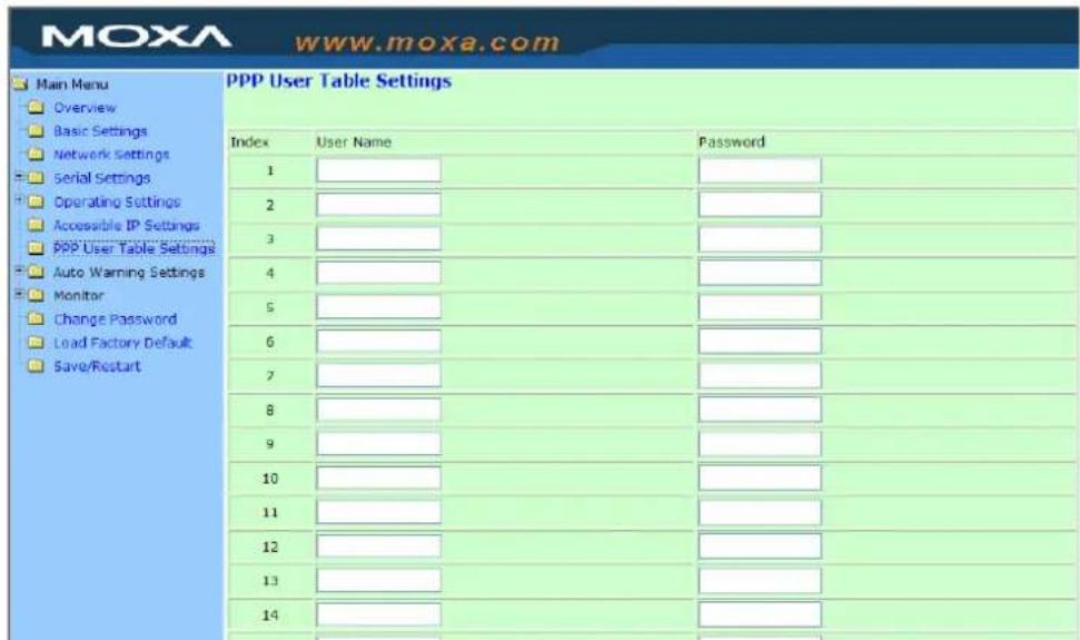
Auto Warning Settings
Auto warning: E-mail and SNMP Trap
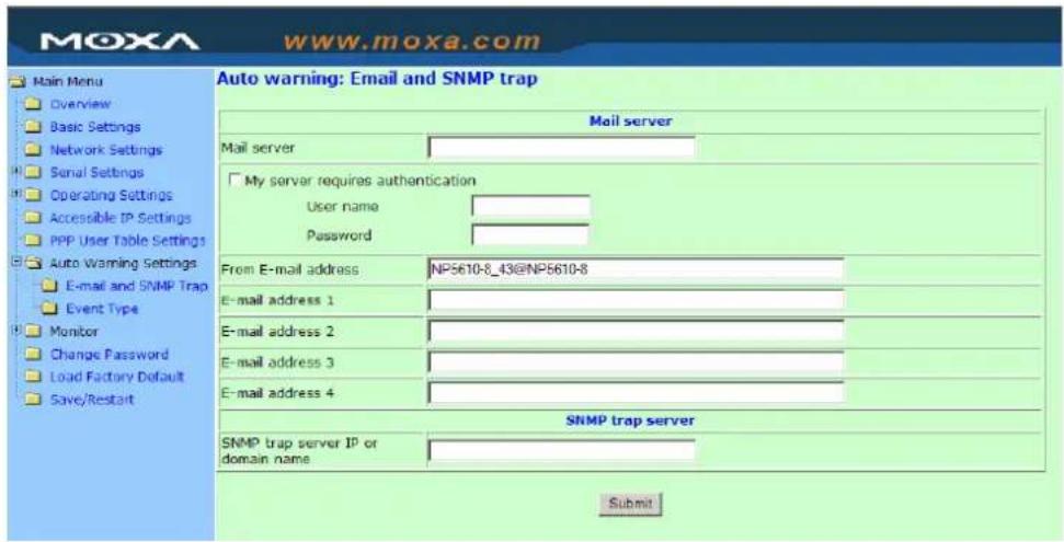
Mail Server
Mail server
| Setting Factory Default Necessity | ||
| IP or Domain Name None Optional |
User name
| Setting Factory Default Necessity | ||
| 1 to 15 characters None Optional |
Password
| Setting Factory Default Necessity | ||
| 1 to 15 characters None Optional |
From E-mail address
| Setting Factory Default Necessity | ||
| 1 to 63 characters None Optional |
E-mail address 1/2/3/4
| Setting Factory Default Necessity | ||
| 1 to 63 characters None Optional |

ATTENTION
Consult your Network Administrator or ISP for the proper mail server settings. Auto warning function may not work properly without proper settings. NPort SMTP AUTH support LOGIN, PLAIN, CRAM-MD5 (RFC 2554).
SNMP Trap Server
SNMP trap server IP or domain name
| Setting Factory Default Necessity | ||
| IP or Domain Name None Optional |
Event Type
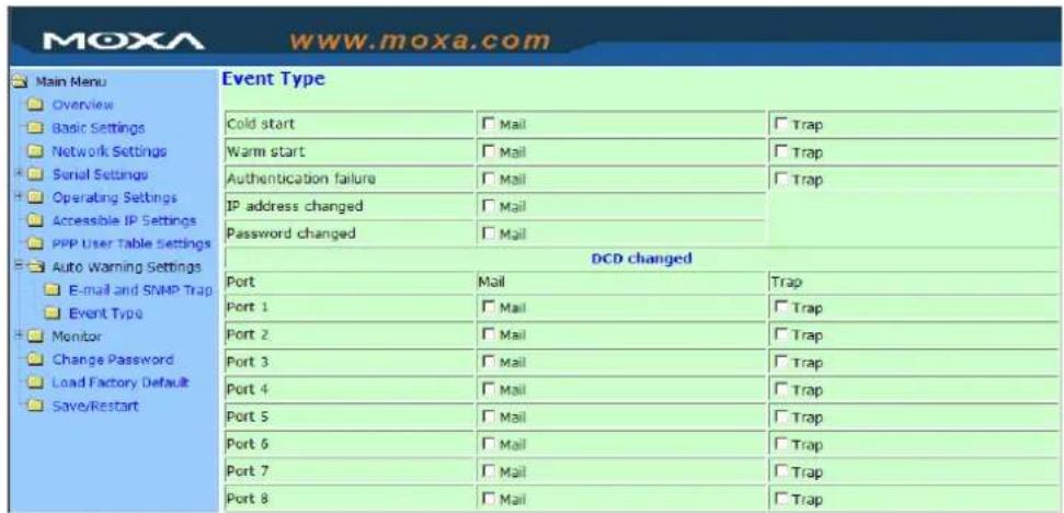
Cold start
This refers to starting the system from power off (contrast this with warm start). When performing a cold start, NPort will automatically issue an Auto warning message by e-mail, or send an SNMP trap after booting up.
Warm start
This refers to restarting the computer without turning the power off. When performing a warm start, NPort will automatically send an e-mail, or send an SNMP trap after rebooting.
Authentication failure
The user inputs a wrong password from the Console or Administrator. When authentication failure occurs, NPort will immediately send an e-mail or send an SNMP trap.
IP address changed
The user has changed NPort's IP address. When the IP address changes, NPort will send an e-mail with the new IP address before NPort reboots. If the NPort is unable to send an e-mail message to the mail server within 15 seconds, NPort will reboot anyway, and abort the e-mail auto warning.
Password changed
The user has changed NPort's password. When the password changes, NPort will send an e-mail with the password change notice before NPort reboots. If the NPort is unable to send an e-mail message to the mail server within 15 seconds, NPort will reboot anyway, and abort the e-mail auto warning.
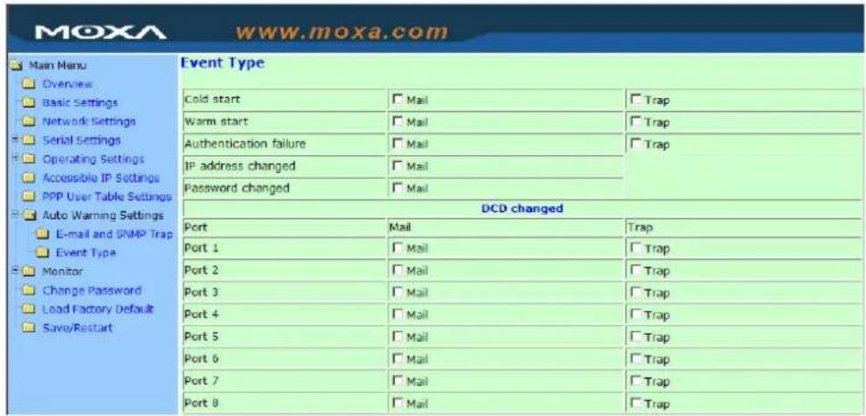
DCD changed
The DCD (Data Carrier Detect) signal has changed, also indicating that the modem connection status has changed. For example, a DCD change to high also means “Connected” between local modem and remote modem. If the DCD signal changes to low, it also means that the connection line is down.
When the DCD changes, NPort 5610 will immediately send an e-mail or send an SNMP trap.
DSR changed
The DSR (Data Set Ready) signal has changed, also indicating that the data communication equipment's power is off. For example, a DSR change to high also means that the DCE is powered ON. If the DSR signal changes to low, it also means that the DCE is powered off.
When the DSR changes, NPort 5610 will immediately send an e-mail or send an SNMP trap.
| Setting Factory Default Necessity | ||
| Enable, Disable Disable Optional |
This feature helps the administrator manage how the NPort sends e-mail to pre-defined e-mail boxes when the enabled events—such as Cold start, Warm start, Authentication failure, etc.—occur. To configure this feature, click the Event Type Mail checkbox.
Trap
| Setting Factory Default Necessity | ||
| Enable, Disable Disable Optional |
This feature helps the administrator manage how the NPort sends SNMP Trap to a pre-defined SNMP Trap server when the enabled events—such as Cold start, Warm start, Authentication failure, etc.—occur. To configure this feature, click the Event Type Trap checkbox.

ATTENTION
DCD changed and DSR changed event only supported by those models, which have these two signals. For example NPort 5210, 5410 and NPort 5610.
Monitor
Monitor Line
Click Line under Monitor to show the operation mode and status of each connection (IPx), for each of the four serial ports.
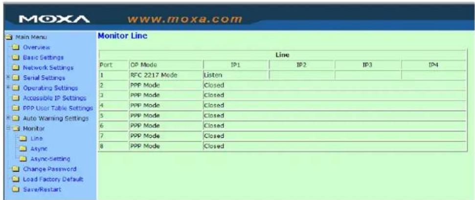
Monitor Async
Click Async under Monitor to show the current status of each of the four serial ports.
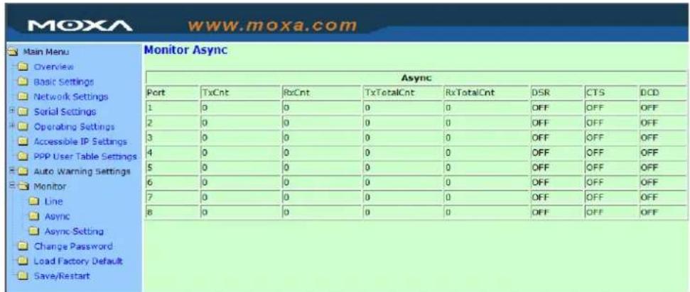
Monitor Async-Settings
Click Async Setting under Monitor to show the run-time settings for each of the four serial ports.
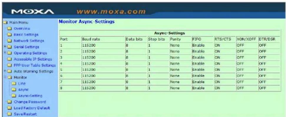
Change Password
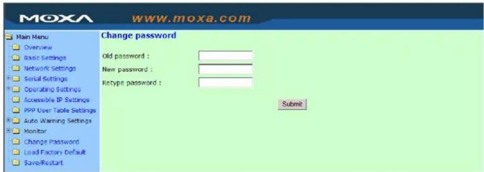
Input the "Old password" and "New password" to change the password. Leave the password boxes blank to erase the password. In this case, the NPort will not have password protection.

ATTENTION
If you forget the password, the ONLY way to configure NPort is by using the Reset button on NPort's casing to Load Factory Defaults.
Remember to export the configuration file using Windows Administrator when you finish the configuration. By using the Import function of Windows Administrator, your configuration can be re-loaded into NPort after resetting the parameters to their factory defaults. Refer to Chapter 6 for more details about the Export and Import function.
Load Factory Defaults
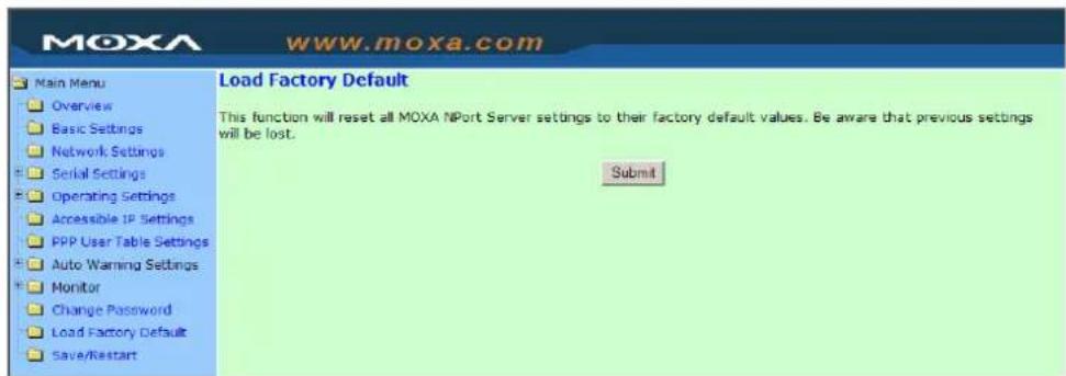
This function will reset all of NPort's settings to their factory default values. Be aware that previous settings will be lost.
NPort Administrator and Web Console are two powerful tools that can be used to configure the settings of your NPorts. Choose the method that is most convenient for you. Note that this chapter uses NPort 5230 as an example to introduce the installation and configuration of NPort Administration Suite. The functions and definitions are the same as for NPort 5600.
The following topics are covered in this chapter:
Overview
□ Installing NPort Administrator
Configuration
▶ Broadcast Search
▶ Unlock Password Protection
▶ Configuring NPort 5600
▶ Upgrading Firmware
▶ Export/Import
Monitor
Port Monitor
□ COM Mapping
NPort Administrator lets you easily install and configure your NPort 5600 Series product over the network. NPort Administrator provides five function groups that ease the installation process, allow off-line COM mapping, and provide monitoring and IP location server functions.
NPort Administrator is an integrated software suite that bundles NPort Administrator and the IP Serial Library, and provides everything you need to remotely manage, monitor, and modify your NPort from a remote location.
Installing NPort Administrator
- Once the Setup program starts running, click Next when the Welcome window opens to proceed with the installation.
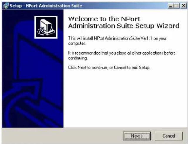
- Click Next to install program files in the default directory, or select an alternative location.
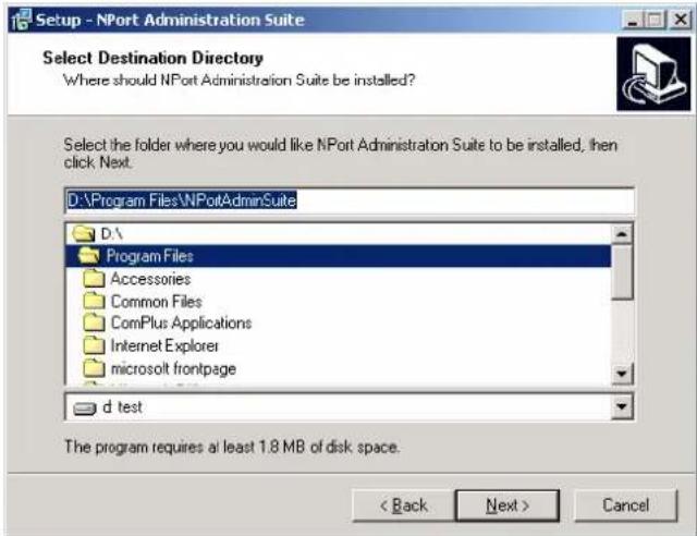
- Click Next to install the program using the default program name, or select a different name.
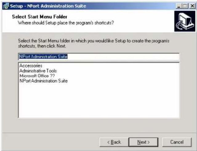
- Click Install to proceed with the installation.
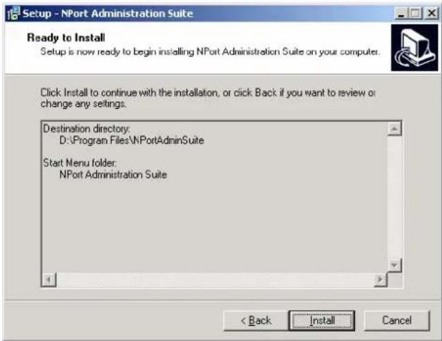
- The Installing window reports the progress of the installation.
- Read through the installation notes and then click Next to proceed.
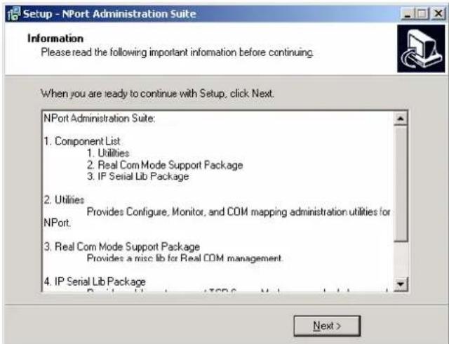
- Click Finish to complete the installation of NPort Administration Suite.
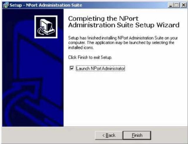
Configuration
The Administrator-Configuration window is divided into four parts.
- The top section contains the function list and online help area. (Windows NT does not support this .chm file format.)
• The five Administrator function groups are listed in the left section.
- A list of NPort 5600 serial device servers, each of which can be selected to process user requirements, is displayed in the right section.
- The activity Log, which displays messages that record the user's processing history, is shown in the bottom section.
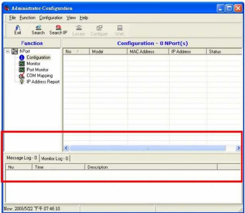
Broadcast Search
The Broadcast Search function is used to locate all NPorts that are connected to the same LAN as your computer.
- Since the Broadcast Search function searches by MAC address and not IP address, all NPorts connected to the LAN will be located, regardless of whether or not they are part of the same subnet as the host.
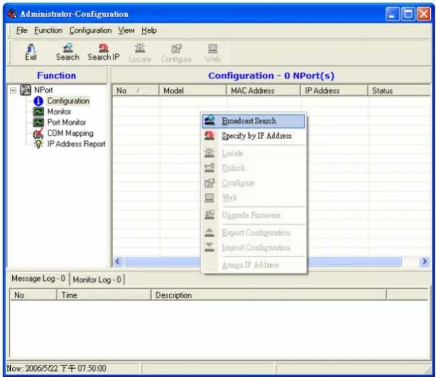
- The Broadcast Search window will open and display the Model, IP Address, MAC Address, and Progress (of the search for that particular device).
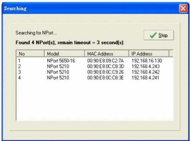
- When the search is complete, the Broadcast Search window closes, and the NPorts that were located are displayed in the right pane of the Administrator window.
For the example shown here, NPort Administrator found 4 NPort Serial Device Servers on the LAN. As you can see, 2 of the 4 NPorts have password protection, which is indicated by Lock under Status.
To configure one of the listed NPorts, place the cursor over the row displaying that NPort's information, and then right click.
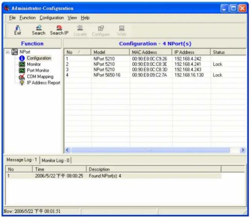

ATTENTION
Before modifying NPort 5600's configuration, use Broadcast Search to locate all NPort 5600s connected to the LAN, or use Specify by IP Address to locate a particular NPort 5600.
Unlock Password Protection
- If the NPort is password protected, then you will not be able to use the right click method to open the configuration page.
![Error Target is password protected. Please [Unlock] first. OK](/content/2026/06/1263692/images/76f26e9c74bf1472e42864dcb442d0b12637f796ad2a3c9165cd6af5fc9c6470.jpg)
- Instead, select an NPort with "Lock" status, right click the locked NPort, and then select the Unlock button.
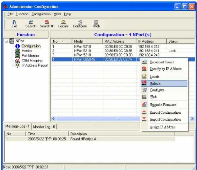
- After entering the correct password, the Administrator will display a message box as shown here. The NPort is now unlocked.
- The previous "Lock" status will switch to "Unlock" status.
Administrator will keep this NPort in the Unlock status throughout this Administrator session.
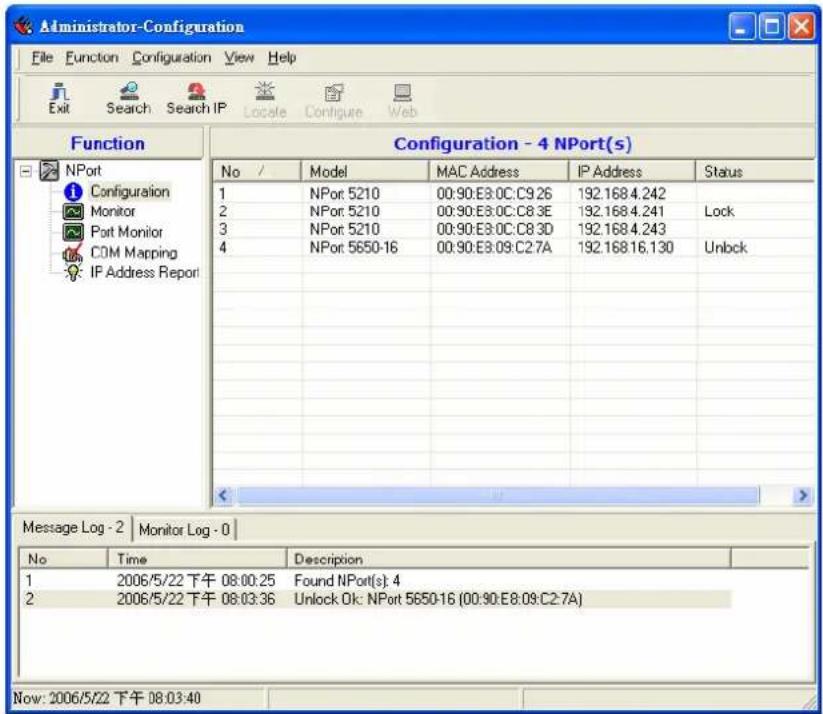
The six states are as follows (note that the term Fixed is borrowed from the standard fixed IP address networking terminology):
Lock
The NPort is password protected, "Broadcast Search" was used to locate it, and the password has not yet been entered from within the current Administrator session.
Unlock
The NPort is password protected, "Broadcast Search" was used to locate it, and the password has been entered from within the current Administrator session. Henceforth during this Administrator session, activating various utilities for this NPort will not require re-entering the server password.
Blank
The NPort is not password protected, and "Broadcast Search" was used to locate it.
Fixed
The NPort is not password protected, and "Search by IP address" was used to locate it.
Lock Fixed
The NPort is password protected, "Specify by IP address" was used to locate it, and the password has not yet been entered from within the current Administrator session.
Unlock Fixed
The NPort is password protected, "Specify by IP address" was used to locate it, and the password has been entered from within the current Administrator session. Henceforth during this Administrator session, activating various utilities for this NPort will not require re-entering the server password.
Configuring NPort 5600
- To start NPort Administrator, click Start → NPort Administration Suite → NPort Administrator.
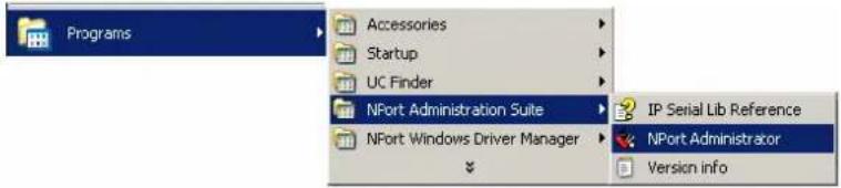
- Input the password to Unlock the NPort.
Right click a specific NPort and select configure to start the configuration.
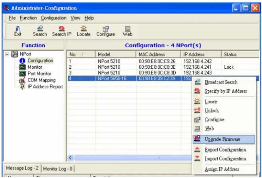
- The progress bar shows that Administrator is retrieving configuration information from the specific NPort.
- Refer to Chapter 5 for each parameter's function definition.
To modify the configuration, you must first click in the modify box to activate the parameter setting box.
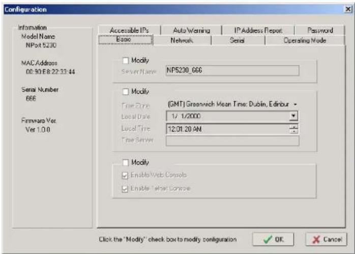
![Configuration Information Model Name NPot 5230 MAC Address 00:90 E8.22:33:44 Serial Number 666 Hardware Vet Ver 1.0.0 Accessible IPs Auto Warning IP Address Report Password Basic Network Serial Operating Mode Modify Server Name:NP5230_666 Modify Time Zone [ONT] Greenwich Mean Time, Dublin, Edinburgh Local Date 1/ 1/2000 Local Time 12/01:20 AM Time Server Modify Enable Web Consolb Enable Retnet Consolc Click the 'Modify' check box to modify configuration OK Cancel](/content/2026/06/1263692/images/45324b15fd2a280f1e80d9a6b73ca03f2d57e5734df8fc8164e090ca5f3d2db6.jpg)
![Configuration Information Model Name: NPon 5230 MAC Address 00:50:EB:22:33:44 Serial Number 666 Firmware Ver. Ver 1.0.0 Accessible IPs Basic Auto Warning Network IP Address Report Serial Password Operating Mode Modify Server Name: NP5230_666 Modify Time Zone [GMT] Greenwich Mean Time Dublin, Edinburgh Local Date 5/13/2003 Local Time May, 2003 Sun Mon Tue Wed Thu Fri Sat Modify Enable Web Enable Tset Today: 4/28/2003 Click the "Modify" check box to modify configuration. OK Cancel](/content/2026/06/1263692/images/fe13c93632badef5ea7d7bf4f73f127b52f1d58b0002710fb26e6a4ec8965d29.jpg)

ATTENTION
You can simultaneously modify the configurations of multiple NPort 5600s that are of the same model.
To select multiple NPort 5600s, hold down the Ctrl key when selecting additional NPort 5600s, or hold down the Shift key to select a group of NPort 5600s.
Upgrading Firmware
- Input the password to Unlock the NPort, and then right click a specific NPort and select the Upgrade Firmware function to start upgrading the firmware.
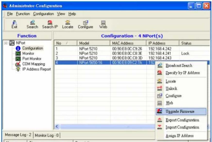
- Select the correct ROM file to be downloaded to the NPort. Visit Moxa's website at www.moxa.com for the latest firmware release.
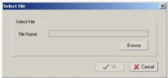
- Wait patiently while the Upgrade Firmware action is being processed.
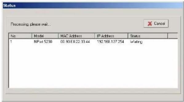

ATTENTION
You can simultaneously upgrade the firmware of multiple NPort 5600s that are of the same model.
To select multiple NPort 5600s, hold down the Ctrl key when selecting an additional NPort 5600, or hold down the Shift key to select a block of NPort 5600s.
Export/Import
- Input the password to Unlock the NPort, and then right click a specific NPort and select the Export function to start Exporting the configuration file.
The Export Configuration function is a handy tool that can be used to produce a text file containing the current configuration of a particular NPort.
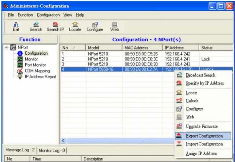
- The Import Configuration function is used to import an NPort configuration from a file into one or more of the same model NPort.
To import a configuration, first select the target servers (use the left mouse button to select servers; simply hold down the Ctrl key when selecting the second, third, etc., NPort).
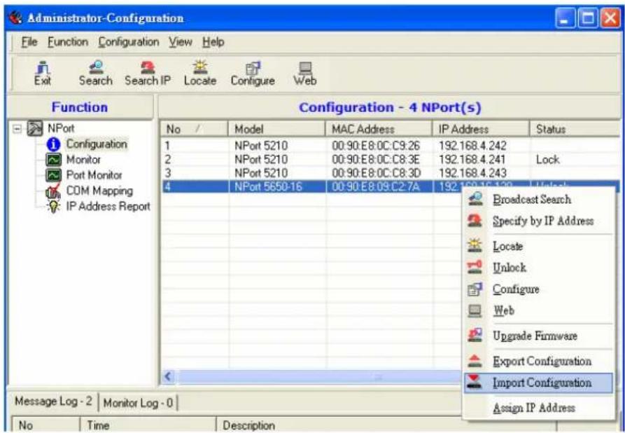

ATTENTION
You can simultaneously import the same configuration file into multiple NPort 5600s that are of the same model.
To select multiple NPort 5600s, hold down the Ctrl key when selecting an additional NPort 5600, or hold down the Shift key to select a block of NPort 5600s.
Monitor
There are two methods available to start the Monitor function.
- First use Broadcast Search under the Configuration Function group, and then click Monitor Add Target Select target from the list.
- First click Monitor, and then Add Target → Rescan.
- Select Broadcast under the Configuration menu bar item.
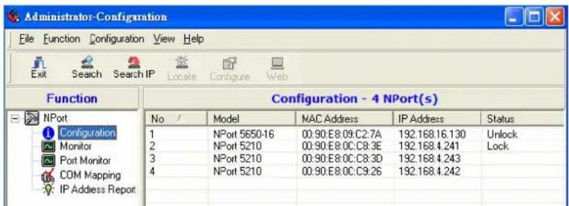
4. Click Monitor.
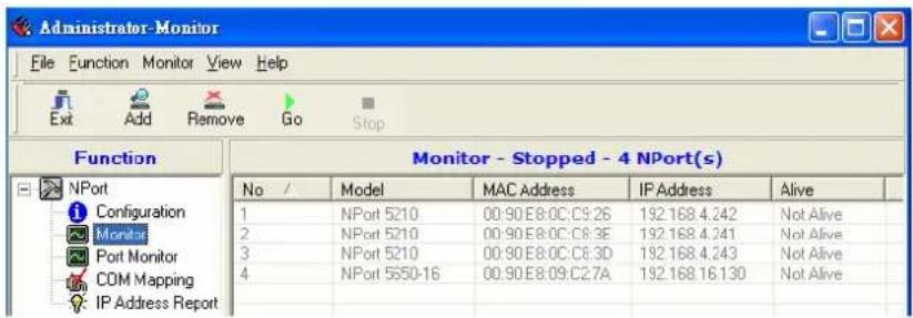
5. Select Add Target.
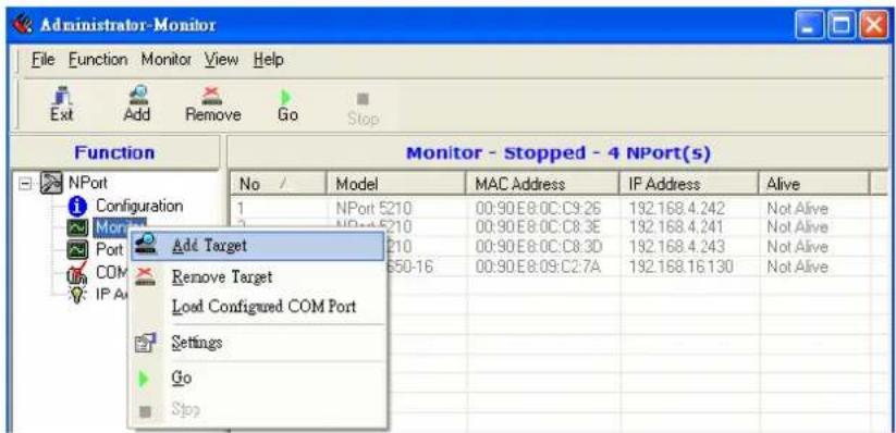
When you select add target, you will see an NPort list that looks the same as when using Configuration → Broadcast Search.
6. Check the NPort you would like to Monitor, and then click OK.
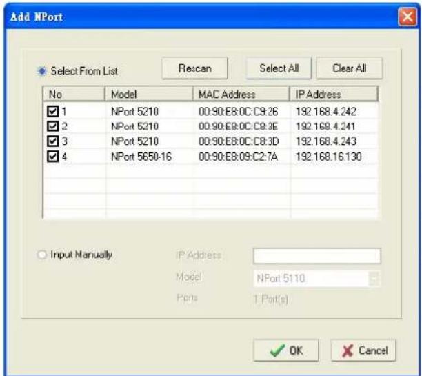
- The NPort list will now appear on the Monitor screen.
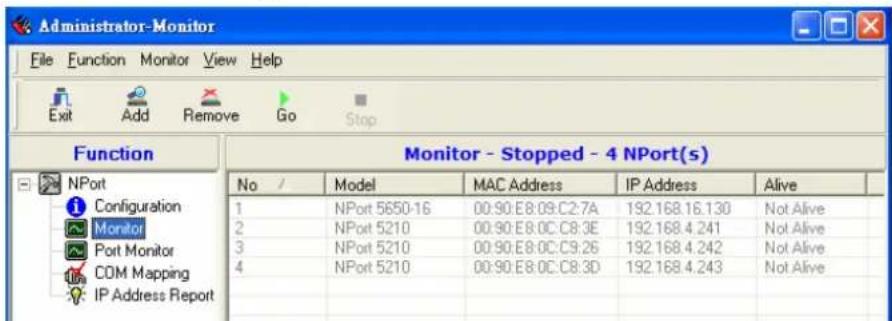
- Right click the panel and select Settings.
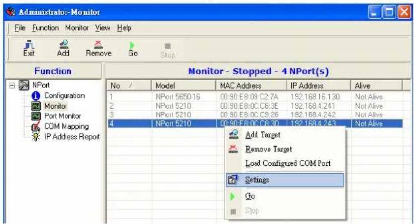
- Select or de-select Monitor Items. Use the single arrowhead buttons to move highlighted items from one box to the other. Use the double arrowhead buttons to move all items in one box to the other.
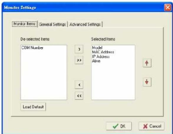
- Select a Refresh Rate (the default is 3 seconds).
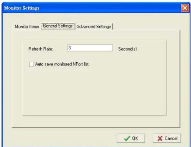
- Select Display warning message for new event or Play warning music for new event. In the second case, you must enter the path to the WAV file that you want to be played. "New event" means that one of the 5600s in the monitor is "Alive" or "Not Alive," or has lost connection with the Monitor program.
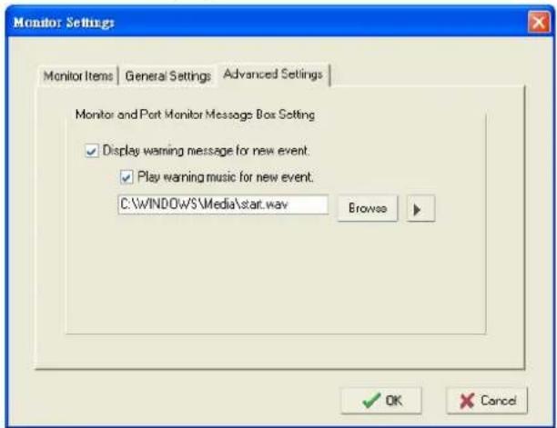
- Right click and select Go to start the Monitor.
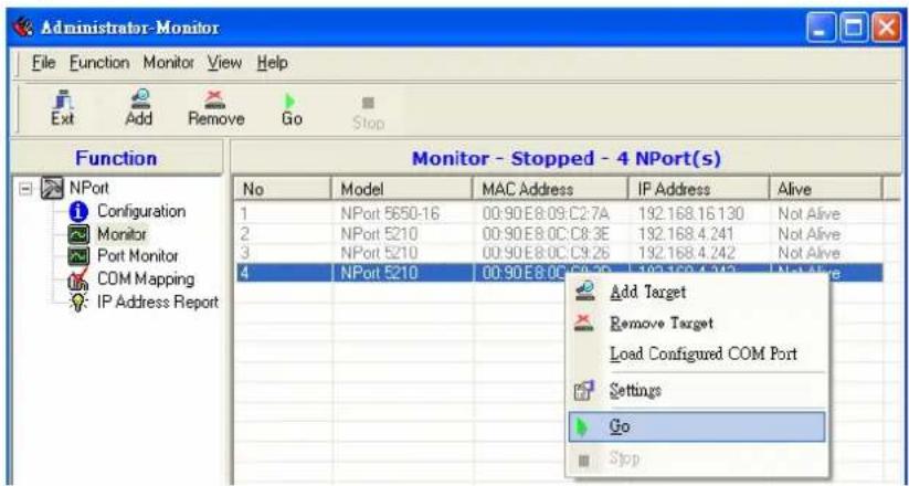
- For this example, the 5 NPorts shown in the list will be monitored.
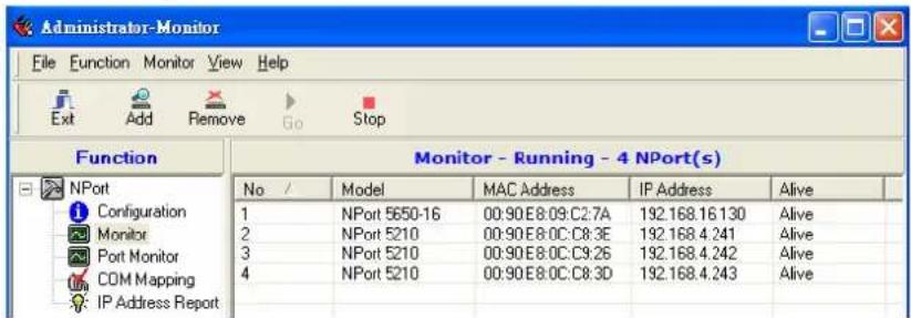
- When one of the NPorts loses connection with the Monitor program, a warning alert will display automatically. The warning music will be played at the same time.
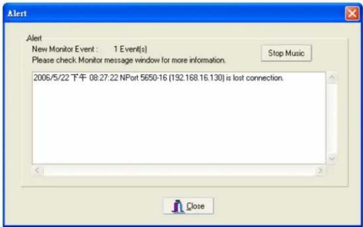
- In the Monitor screen, you can see that the "Not Alive" NPort is marked with red color.
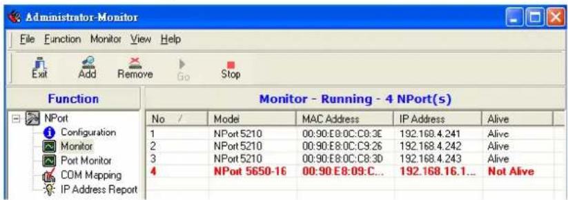
- Click the Alive column. The Monitor program will sort the NPort list and put all "Not Alive" NPorts at the top of the list.
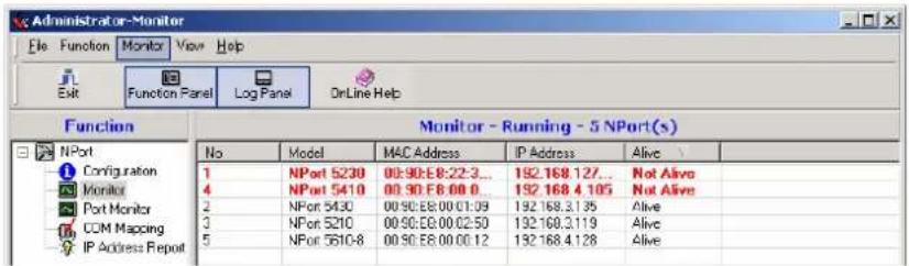
- If the NPort gets reconnected, a warning will be displayed to remind the user the NPort is now "Alive."
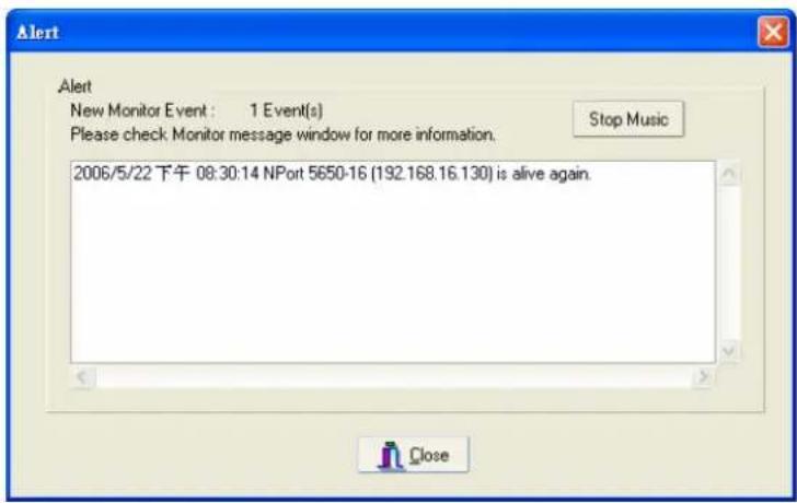
- The NPort that was reconnected, and is now "Alive," will be shown in black color.
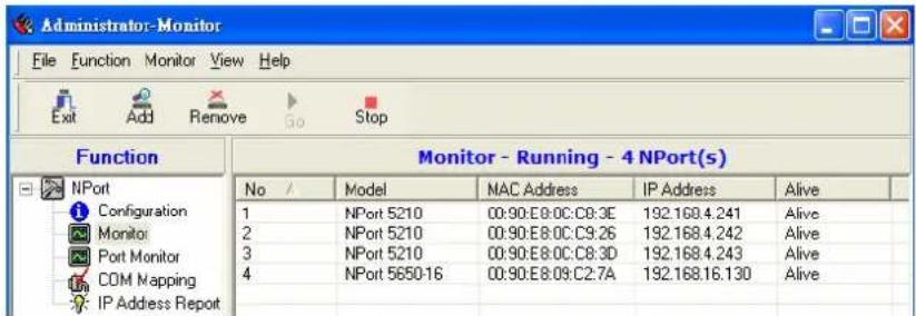
Port Monitor
- The process described here is the same as in the previous "Monitor" section. The only difference is that you can select more items under Port Monitor than under Monitor.
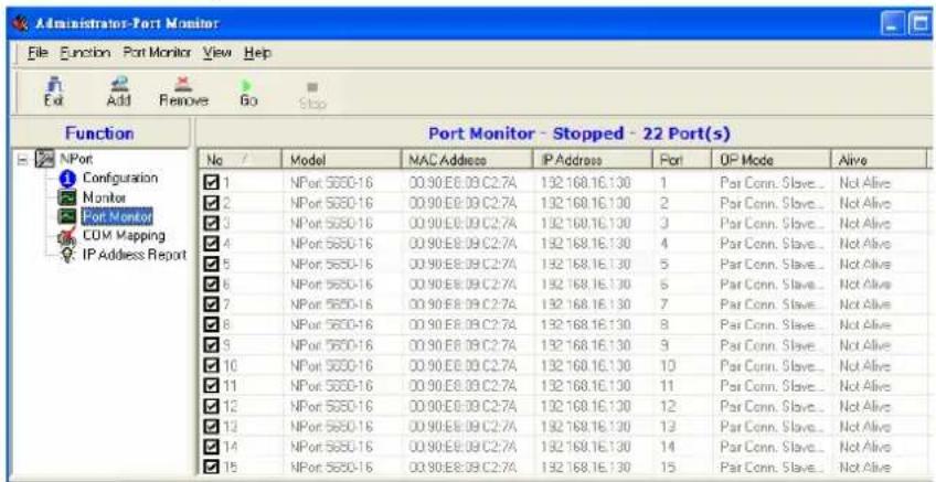
- Select or de-select Monitor Items. Use the single arrowhead buttons to move highlighted items from one box to the other. Use the double arrowhead buttons to move all items from one box to the other.
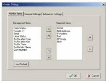
COM Mapping
NPort Administration Suite comes with Windows 95/98/ME/NT/2000/XP Real COM drivers. After you install Windows Administration Suite, there are two ways to set up the NPort's serial port as your host's remote COM port. The first way is with On-line COM Mapping. On-line COM Mapping will check to make sure the NPort is connected correctly to the network and then install the driver on the host computer.
The second way is with Off-line COM Installation, without connecting the NPort to the network first. Off-line COM Mapping can decrease the system integrator's effort by solving different field problems. Via off-line installation, the user can process the host software installation and then install the NPort to different fields.
Use the following procedure to map COM ports:
-
On-line COM Mapping: Connect NPort to the network → Set NPort to the proper IP address → Map COMs to your host → Apply Change.
-
Off-line COM Mapping: Map COMs to your host → Apply Change → Connect NPort to the network → Configure NPort's IP address.
On-line COM Mapping
- Broadcast Search for NPorts on the network.
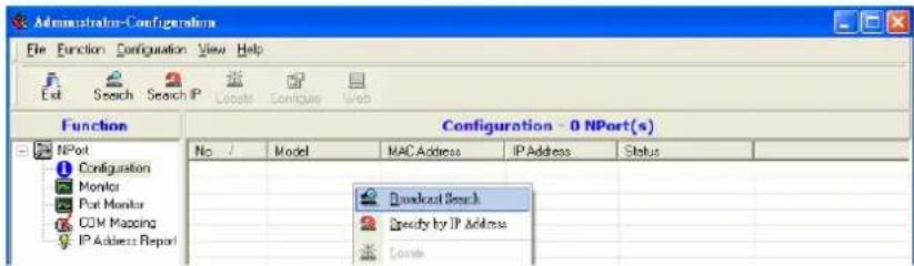
- Select the COM Mapping function group.
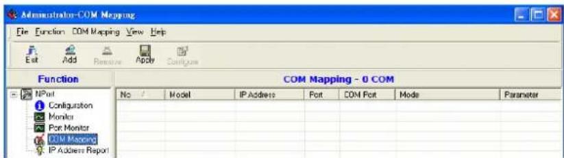
- Add the target to which you would like to map COM ports.
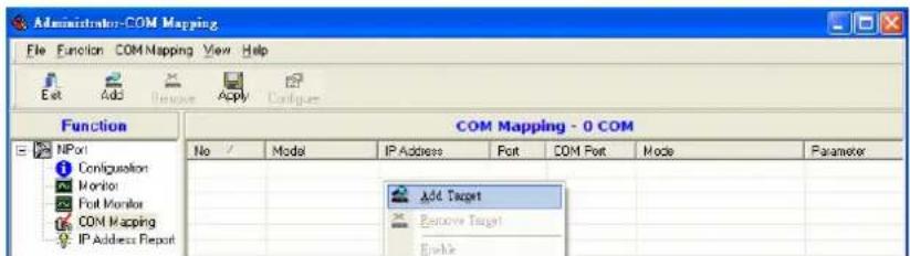
- The NPort list that appears is the list generated by the previous Broadcast Search. Select the NPort to which you would like to map COM ports.
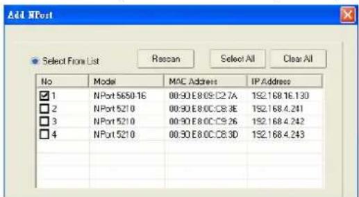
- Select COM Setting to modify COM No., default setting, etc.
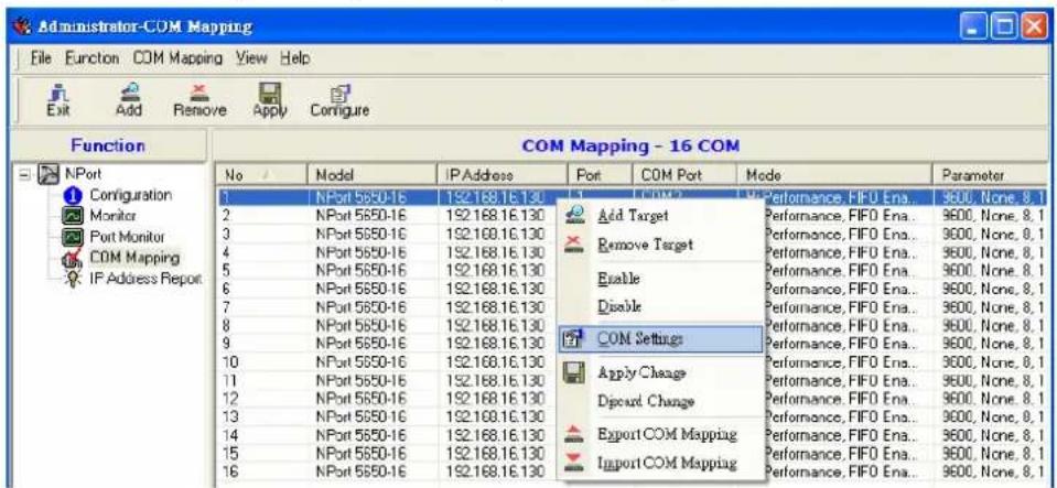
- Select the COM No. COM ports that are "In use" or "Assigned" will also be indicated in this drop-down list.
If you select multiple serial ports or multiple NPorts, remember to check the "Auto Enumerating" function to use the COM No. you select as the first COM No.
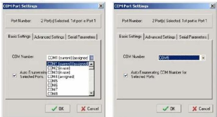
Hi-performance mode is the default for Tx mode. If the driver completes sending data out to the NPort, the driver will respond "Tx Empty" to the program.
Under classical mode, the driver will not notify the user's program that Tx is completed until all Tx data has been sent out from the NPort; this mode will cause lower throughput. If you want to ensure that all data is sent out before further processing, classical mode is recommended.
Enable/Disable Tx/Rx FIFO. If disabled, NPort will send one byte each time the Tx FIFO becomes empty; and an Rx interrupt will be generated for each incoming byte. This will result in a faster response and lower throughput. If you want to use XON/XOFF flow control, we recommend setting FIFO to Disable.
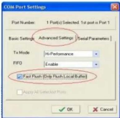
Fast Flush (only flush local buffer)
We have added one optional Fast Flush function to Moxa's new NPort Real COM driver. NPort Administrator Suite for 2G NPort adds it after version 1.2.
For some applications, the user's program will use the Win32 "PurgeComm()" function before it reads or writes data. With our design, after the program uses this Purge Comm() function, the NPort driver will keep querying NPort's firmware several times to make sure there is really no data queued in the NPort firmware buffer, rather than just flushing the local buffer. This kind of design is used because of some special considerations. However, it might take more time (on the order of several hundred milliseconds) than a native COM1, because it needs to work via Ethernet. That's why the native COM ports on the motherboard can work fast with this function call, but NPort requires much more time. In order to accommodate other applications that require a faster response time, the new NPort driver implements a new "Fast Flush" option. Note that by default, this function is disabled.
To begin with, make sure there are some “PurgeComm()” functions being used in your application program. In this kind of situation, you might find that your NPort exhibits a much poorer operation performance than when using the native COM1 port. Once you have enabled the “Fast Flush” function, you can check to see if there has been an improvement in performance.
By default, the optional "Fast Flush" function is disabled. If you would like to enable this function, from the "NPort Administrator," double click the COM ports that are mapped to the NPort, and then select the "Fast Flush" checkbox. You should find that when "Fast Flush" is enabled, the NPort driver will work faster with "PurgeComm().
The Serial Parameter settings shown here are the default settings when the NPort is powered on. However, the program can redefine the serial parameters to different values after the program opens the port via Win 32 API.
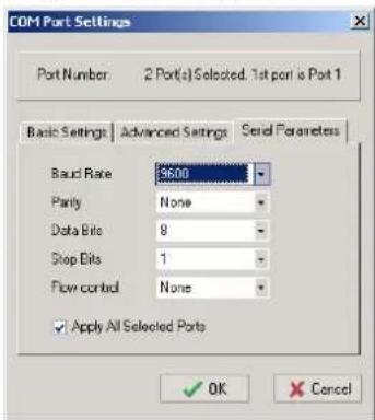
- After setting the COM Mapping, remember to select Apply Change to save the information in the host system registry. The host computer will not have the ability to use the COM port until after Apply Change is selected.
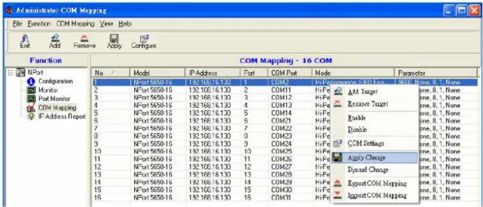
- Select Discard Change to tell Administrator NOT to save the COM Mapping information to the host.
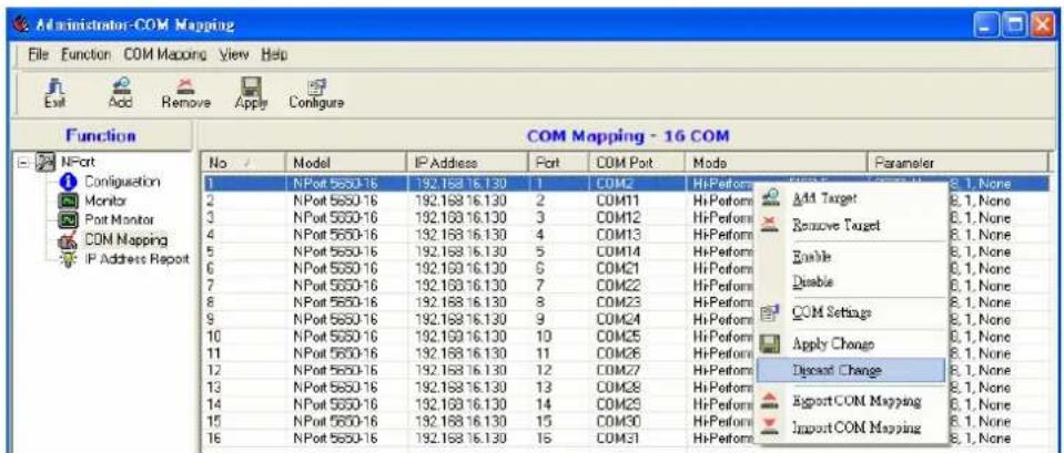
- To save the configuration to a text file, select Export COM Mapping. You will then be able to import this configuration file to another host and use the same COM Mapping settings in the other host.
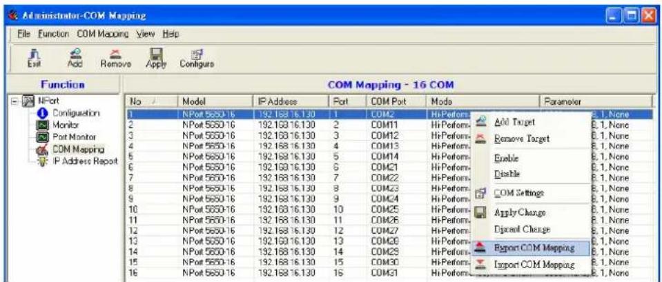
- Add a target by entering the IP address and selecting the Model Name without physically connecting the NPort to the network.
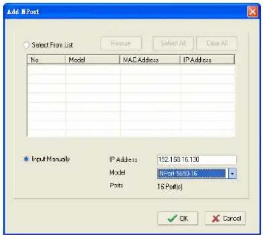
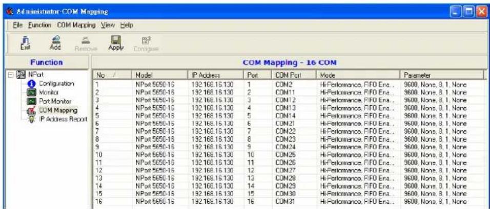
- Select Apply change to effect the changes immediately.
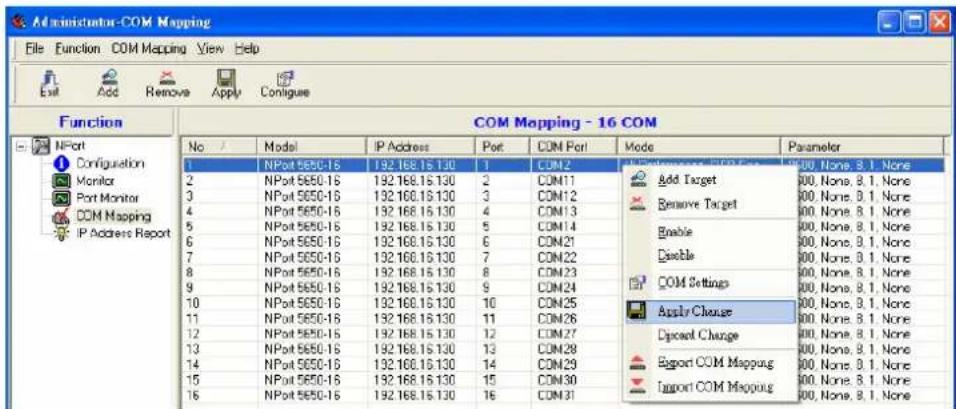
IP Location
When NPort 5600 series products are used in a dynamic IP environment, users must spend more time with IP management tasks. NPort 5600 series products help out by periodically reporting their IP address to the IP location server, in case the dynamic IP has changed.
- Receive NPort's IP location report
-
Centralize NPort's IP management in a dynamic IP environment.
-
Configure NPort with Dynamic IP settings. For example, DHCP, BOOTP and DHCP/BOOTP. Assign the remote Auto IP report server's IP address and UDP port.
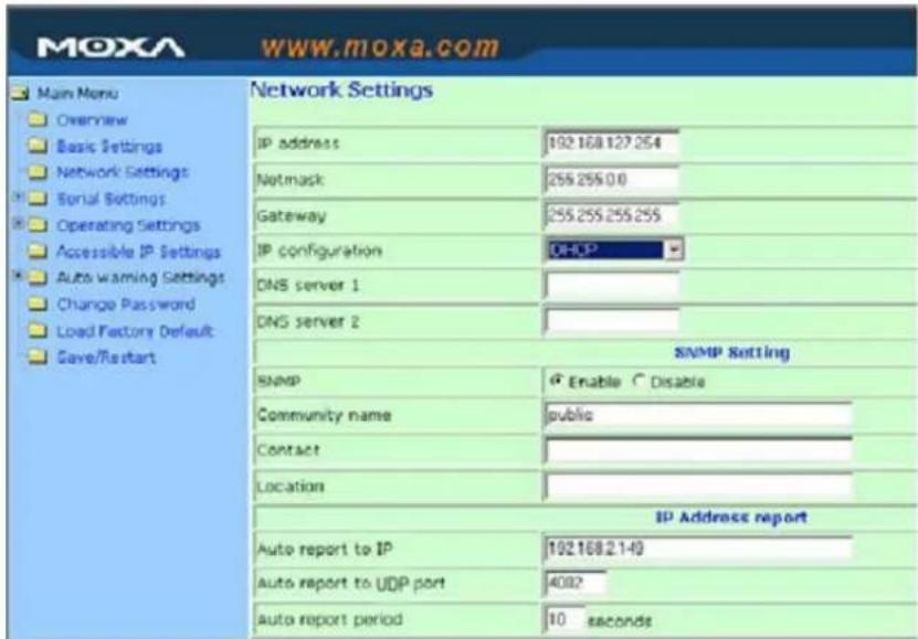
- Select the IP Location Report, and click the right mouse button to select Settings.
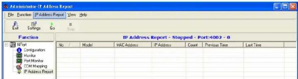
- Then configure the Local Listen Port to be the same as the NPort's "Auto report to UDP port" setting.
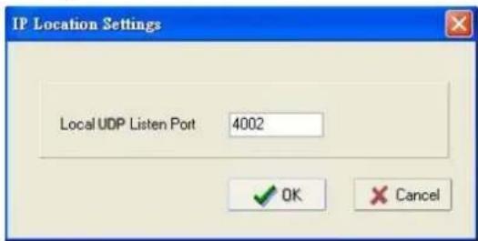
- Click GO to start receiving the Auto IP address report from the NPort.
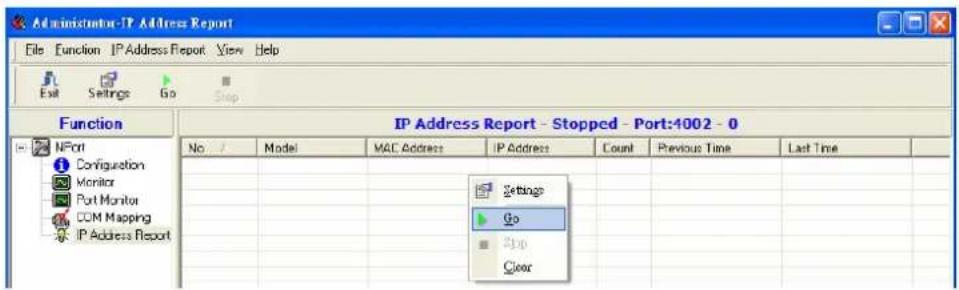
The following topics are covered in this chapter:
Overview
☐ IP Serial LIB Function Groups
Example Program
Overview
What is IP Serial Library?
IP Serial Library is a Windows library with frequently used serial command sets and subroutines. IP Serial Library is designed to reduce the complexity and poor efficiency of serial communication over TCP/IP. For example, Telnet can only transfer data, but it can't monitor or configure the serial line's parameters.
Why Use IP Serial Library?
For programmers who are familiar with serial communication, IP Serial Library provides well-designed function calls that have the same style as Moxa's PComm Library.
IP Serial Library is amazingly simple and easy to understand. By including it in your VB, C, or Delphi programming environment, you can program your own TCP/IP application with the ability to control serial communication parameters.
NPort Serial Device Servers use 2 TCP ports for communication between the NPort and host computer's Real COM driver. NPort uses a data port and command port to provide pure data transfer without decode and encode. Compared to using only one TCP port to control serial communication (such as RFC 2217), IP Serial Library uses a command port to communicate with NPort in user's program. IP Serial Library not only runs with excellent efficiency but also runs without any decode or encode problems.
How to install IP Serial Library?
IP Serial Lib comes with the NPort Administration Suite. Refer to the IPSerial directory for more detail about the function definitions.
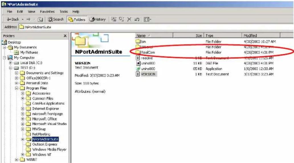
IP Serial LIB Function Groups
| Server Control | Port Control | Input/Output | Data | Port Inquiry | Status | Miscellaneous |
| nsio_init | nsio_open | nsio_read | nsio_lstatus | nsio_break | ||
| nsio_end | nsio_close | nsio_SetReadTimeouts | nsio_data_status | nsio_break_on | ||
| nsio_resetserver | nsio_ioctl | nsio_write | nsio_break_off | |||
| nsio_checkalive | nsio_flowctrl | nsio_SetWriteTimeouts | nsio_breakcount | |||
| nsio_DTR | ||||||
| nsio_RTS | ||||||
| nsio_lctrl | ||||||
| nsio_baud | ||||||
| nsio_resetport |
Example Program
| char nportip="192.168.1.10"; | |
| char buffer[255]; | /*data buffer, 255 chars */ |
| int port = 1; | /*1st port */ |
| int portid; | /* port handle */ |
| nsio_init(); | /*initial IP Serial Library */ |
| portid = nsio_open(nportip, port); | /*1st port, nport IP=192.168.1.10 */ |
| nsio_ioctl(portid, B9600, (BIT_8 | STOP_1 | P_NONE)); | /*set 9600, N81 */ |
| sleep(1000); | /* wait for 1000 ms for data */ |
| nsio_read(port, buffer, 200); | /* read 200 bytes from port 1 */ |
| nsio_close(portid); | /* close this serial port */ |
| nsio_end(); | /* close IP Serial Library */ |
In this appendix, we cover the following topics.
□ Port Pinout Diagrams
Ethernet Port Pinouts
Serial Port Pinouts
□ Cable Wiring Diagrams
Ethernet Cables
Serial Cables for NPort 5610/5650 (RS-232)
➢ Serial Cables for NPort 5630 (RS-422/4-wire RS-485)
➢ Serial Cables for NPort 5630 (2-wire RS-485)
➢ Serial Cables for NPort 5650 (RS-422/4-wire RS-485)
➢ Serial Cables for NPort 5650 (2-wire RS-485)
➢ Pin Assignments for DB9 and DB25 Connectors
Port Pinout Diagrams
Ethernet Port Pinouts
| Pin | RS-232 |
| 1 | Tx+ |
| 2 | Tx- |
| 3 | Rx+ |
| 6 | Rx- |
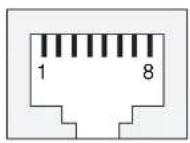
Serial Port Pinouts
RS-232 Port Pinouts for NPort 5610
| Pin | RS-232 |
| 1 | DSR (in) |
| 2 | RTS (out) |
| 3 | GND |
| 4 | TxD (out) |
| 5 | RxD (in) |
| 6 | DCD (in) |
| 7 | CTS (in) |
| 8 | DTR (out) |
RS-422/485 Port Pinouts for NPort 5630
| Pin | RS-4224-wire RS-485 | 2-wireRS-485 |
| 1 | --- | |
| 2 | --- | |
| 3 | TxD+ | --- |
| 4 | TxD- | --- |
| 5 | RxD- | Data- |
| 6 | RxD+ | Data+ |
| 7 | GND | GND |
| 8 | --- | --- |
RS-232/422/485 Port Pinouts for NPort 5650
| Pin | RS-232 | RS-4224-wire RS-485 | 2-wireRS-485 |
| 1 | DSR | --- | --- |
| 2 | RTS | TxD+ | --- |
| 3 | GND | GND | GND |
| 4 | TxD | TxD- | --- |
| 5 | RxD | RxD+ | Data+ |
| 6 | DCD | RxD- | Data- |
| 7 | CTS | --- | --- |
| 8 | DTR | --- | --- |
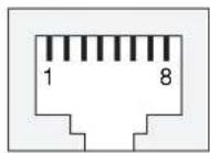
Cable Wiring Diagrams
Ethernet Cables

Cable Wiring
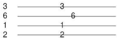

Cable Wiring
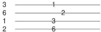
Serial Cables for NPort 5610/5650 (RS-232)
RJ45 (8-pins) to Female DB9
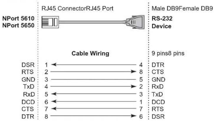
flowchart
graph LR
    A["NPort 5610"] --> B["RJ45 Connector RJ45 Port"]
    C["NPort 5650"] --> B
    B --> D["Device"]
    E["DSR"] --> F["Cable Wiring"]
    G["RTS"] --> F
    H["GND"] --> F
    I["TxD"] --> F
    J["RxD"] --> F
    K["DCD"] --> F
    L["CTS"] --> F
    M["DTR"] --> F
    N["RS-232"] --> O["9 pins8 pins"]
    P["DTR"] --> O
    Q["CTS"] --> O
    R["GND"] --> O
    S["RxD"] --> O
    T["TxD"] --> O
    U["DCD"] --> O
    V["RTS"] --> O
    W["DSR"] --> O
RJ45 (8-pins) to Male DB9
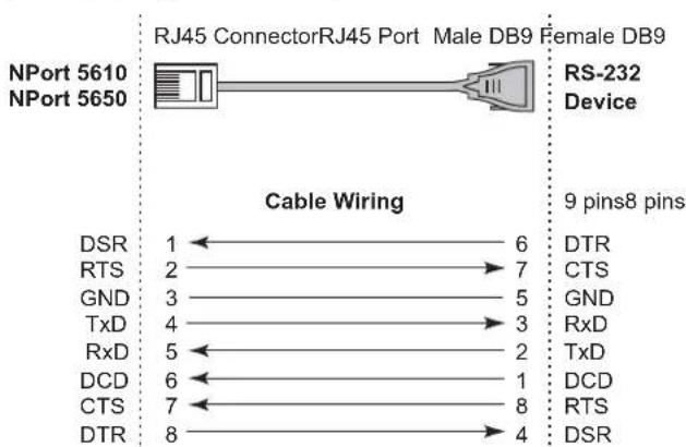
RJ45 (8-pins) to Female DB25
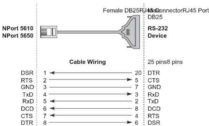
RJ45 (8-pins) to Male DB25
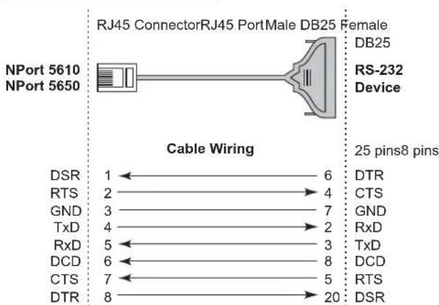
Serial Cables for NPort 5630 (RS-422/4-wire RS-485)
RJ45 (8-pins) to Female DB9
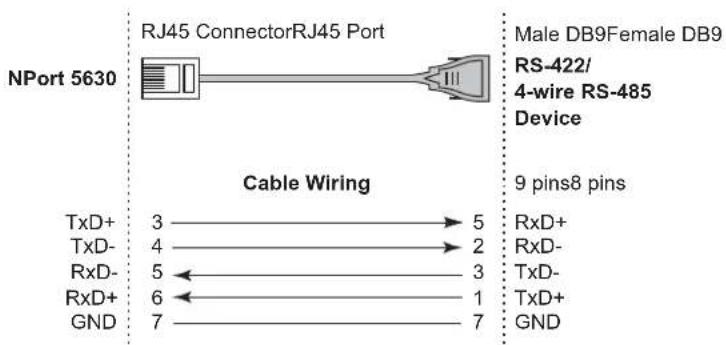
RJ45 (8-pins) to Male DB9
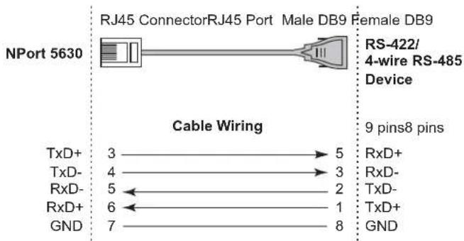
RJ45 (8-pins) to Female DB25
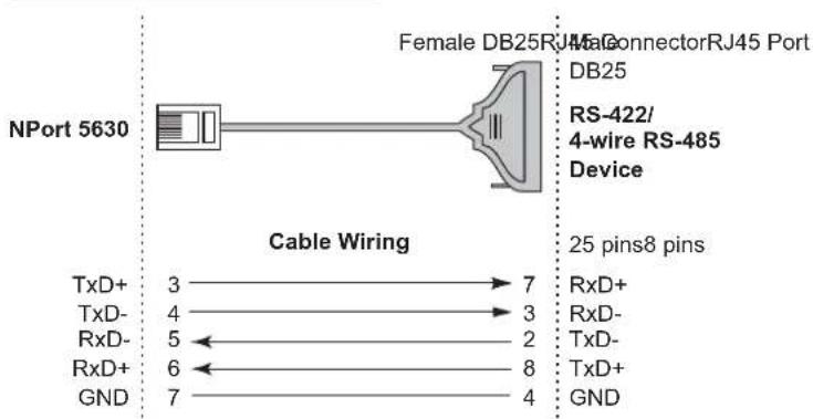
RJ45 (8-pins) to Male DB25
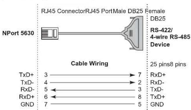
Serial Cables for NPort 5630 (2-wire RS-485)
RJ45 (8-pins) to Female DB9
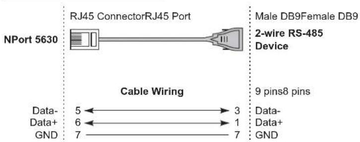
flowchart
graph LR
    A["NPort 5630"] --> B["RJ45 Connector RJ45 Port"]
    B --> C["Device"]
    D["Cable Wiring"] --> E["Data- 5"]
    D --> F["Data+ 6"]
    D --> G["GND 7"]
    H["Male DB9 Female DB9 2-wire RS-485 Device"] --> I["9 pins8 pins"]
    J["Data- Data+ GND"] --> K["3"]
    J --> L["1"]
    J --> M["7"]
RJ45 (8-pins) to Male DB9
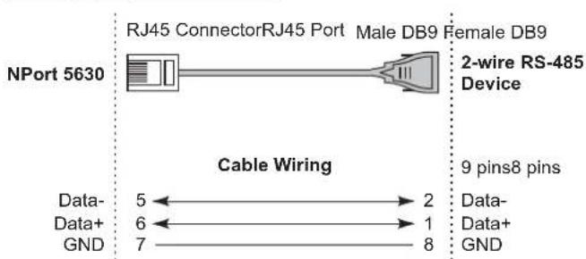
RJ45 (8-pins) to Female DB25
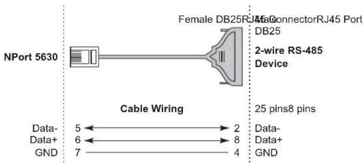
RJ45 (8-pins) to Male DB25

Serial Cables for NPort 5650 (RS-422/4-wire RS-485)
RJ45 (8-pins) to Female DB9
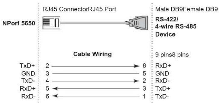
RJ45 (8-pins) to Male DB9
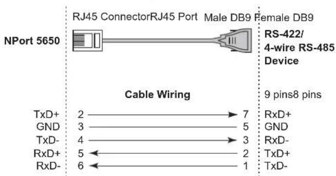
RJ45 (8-pins) to Female DB25
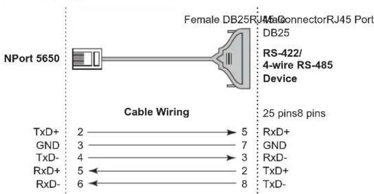
RJ45 (8-pins) to Male DB25
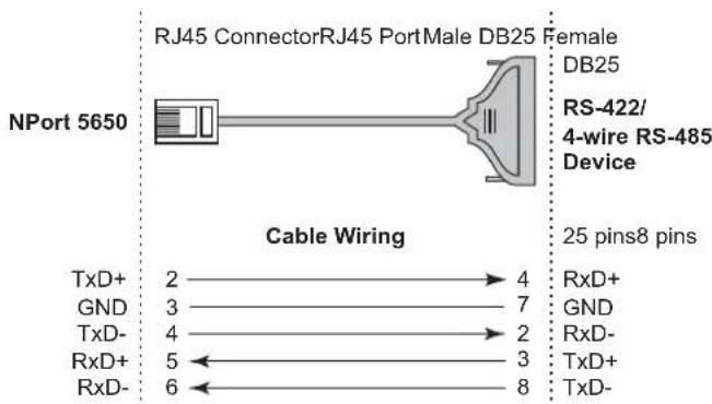
Serial Cables for NPort 5650 (2-wire RS-485)
RJ45 (8-pins) to Female DB9
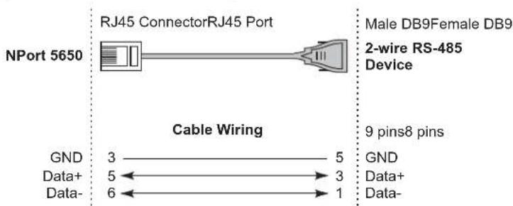
RJ45 (8-pins) to Male DB9
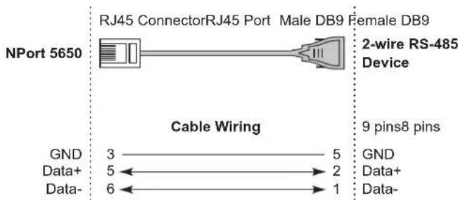
RJ45 (8-pins) to Female DB25
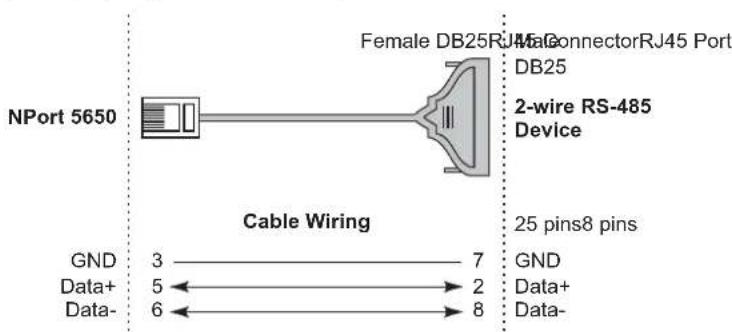
RJ45 (8-pins) to Male DB25
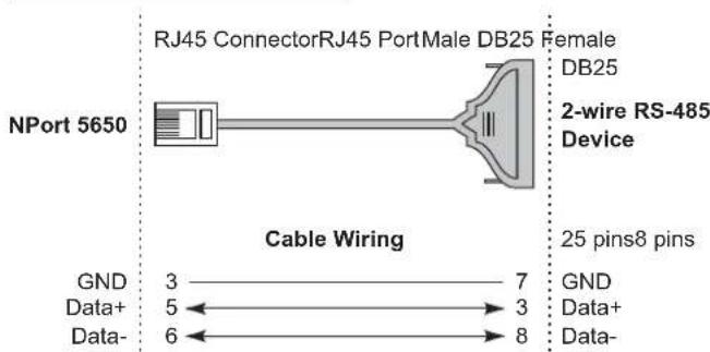
Pin Assignments for DB9 and DB25 Connectors
Pin Assignments for DB9 Male and Female Connectors
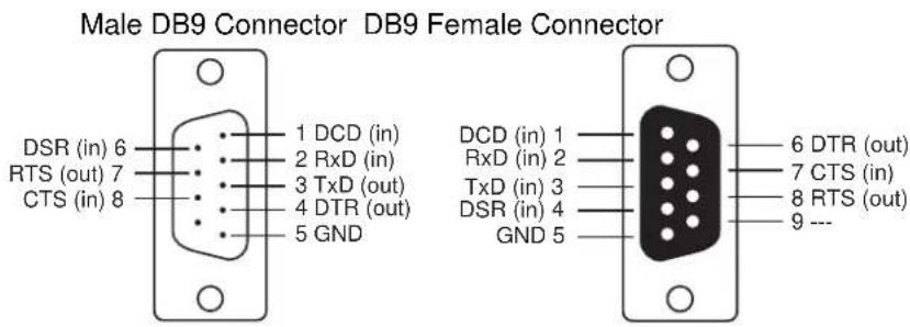
Pin Assignments for DB25 Male and Female Connectors
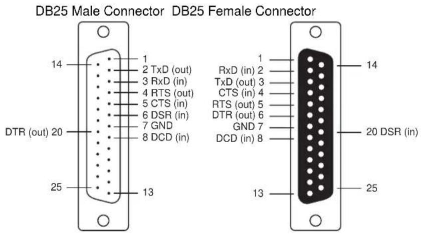
In this appendix, which is included for your reference, we provide a list of Well Known port numbers that may cause network problems if you set NPort 5600 to one of these ports. Refer to RFC 1700 for Well Known port numbers, or refer to the following introduction from the IANA.
The port numbers are divided into three ranges: the Well Known Ports, the Registered Ports, and the Dynamic and/or Private Ports.
The Well Known Ports range from 0 through 1023.
The Registered Ports range from 1024 through 49151.
The Dynamic and/or Private Ports range from 49152 through 65535.
The Well Known Ports are assigned by the IANA, and on most systems, can only be used by system processes or by programs executed by privileged users. The following table shows famous port numbers among the well-known port numbers. For more details, please visit the IANA website at http://www.iana.org/assignments/port-numbers.
| TCP Socket | Application Service |
| 0 | reserved |
| 1 TCP Port | Service Multiplexer |
| 2 | Management Utility |
| 7 | Echo |
| 9 | Discard |
| 11 | Active Users (systat) |
| 13 | Daytime |
| 15 | Netstat |
| 20 FTP data port | |
| 21 FTP CONTROL port | |
| 23 | Telnet |
| 25 SMTP | (Simple Mail Transfer Protocol) |
| 37 Time (Time Server) | |
| 42 Host name server (names server) | |
| 43 | Whois (nickname) |
| 49 (Login Host Protocol) (Login) | |
| TCP Socket Application Service | |
| 53 Domain Name Server (domain) | |
| 79 | Finger protocol (Finger) |
| 80 World Wide Web HTTP | |
| 119 Network news Transfer Protocol (NNTP) | |
| 123 | Network Time Protocol |
| 213 | IPX |
| 160 – 223 Reserved for future use | |
| UDP Socket | Application Service |
| 0 | reserved |
| 2 | Management Utility |
| 7 | Echo |
| 9 | Discard |
| 11 | Active Users (systat) |
| 13 | Daytime |
| 35 | Any private printer server |
| 39 | Resource Location Protocol |
| 42 | Host name server (names server) |
| 43 | Whois (nickname) |
| 49 | (Login Host Protocol) (Login) |
| 53 | Domain Name Server (domain) |
| 69 | Trivial Transfer Protocol |
| 70 | Gopher Protocol |
| 79 | Finger Protocol |
| 80 | World Wide Web HTTP |
| 107 | Remote Telnet Service |
| 111 | Sun Remote Procedure Call (Sunrpc) |
| 119 | Network news Transfer Protocol (NNTP) |
| 123 | Network Time protocol (NTP) |
| 161 | SNMP (Simple Network Mail Protocol) |
| 162 | SNMP Traps |
| 213 | IPX (Used for IP Tunneling) |
(TETP)
NPort 5600 has built-in SNMP (Simple Network Management Protocol) agent software. It supports SNMP Trap, RFC1317 RS-232 like group and RFC1213 MIB-II. The following table lists the standard MIB-II group, as well as the variable implementation for NPort 5600.
RFC1213 MIB-II supported SNMP variables:
| System MIB | Interfaces MIB | IP MIB | ICMP MIB | |
| SysDescr | itNumber | ipForwarding | IcmpInMsgs | |
| SysObjectID | ifIndex | ipDefaultTTL | IcmpInErrors | |
| SysUpTime | ifDescr | iplnReceives | IcmpInDestUnreachs | |
| SysContact | ifType | iplnHdrErrors | IcmpInTimeExcds | |
| SysName | ifMtu | ipInAddrErrors | IcmpInParmProbs | |
| SysLocation | ifSpeed | ipForwDatagrams | IcmpInSrcQuenchs | |
| SysServices | ifPhysAddress | ipInUnknownProtos | IcmpInRedirects | |
| ifAdminStatus | ipInDiscards | IcmpInEchos | ||
| ifOperStatus | ipInDelivers | IcmpInEchoReps | ||
| ifLastChange | ipOutRequests | IcmpInTimestamps | ||
| ifInOctets | ipOutDiscards | IcmpTimestampReps | ||
| ifInUcastPkts | ipOutNoRoutes | IcmpInAddrMasks | ||
| ifInNUcastPkts | ipReasmTimeout | IcmpOutMsgs | ||
| ifInDiscards | ipReasmReqds | IcmpOutErrors | ||
| ifInErrors | ipReasmOKs | IcmpOutDestUnreachs | ||
| ifInUnknownProtos | ipReasmFails | IcmpOutTimeExcds | ||
| ifOutOctets | ipFragOKs | IcmpOutParmProbs | ||
| ifOutUcastPkts | ipFragFails | IcmpOutSrcQuenchs | ||
| ifOutNUcastPkts | ipFragCreates | IcmpOutRedirects | ||
| ifOutDiscards | ipAdEntAddr | IcmpOutEchos | ||
| ifOutErrors | ipAdEntIfIndex | IcmpOutEchoReps | ||
| System MIB | Interfaces MIB IP MIB ICMP MIB | |
| ifOutQLen | ipAdEntNetMask IcmpOutTimestamps | |
| ifSpecific | ipAdEntBcastAddr IcmpOutTimestampReps | |
| ipAdEntReasmMaxSize IcmpOutAddrMasks | ||
| IpNetToMediaIfIndex IcmpOutAddrMaskReps | ||
| IpNetToMediaPhysAddress | ||
| IpNetToMediaNetAddress | ||
| IpNetToMediaType | ||
| IpRoutingDiscards |
| UDP MIB TCP MIB | SNMP MIB | |
| UdpInDatagrams | tcpRtoAlgorithm | snmpInPkts |
| UdpNoPorts | tcpRtoMin | snmpOutPkts |
| UdpInErrors | tcpRtoMax | snmpInBadVersions |
| UdpOutDatagrams | tcpMaxConn | snmpInBadCommunityNames |
| UdpLocalAddress | tcpActiveOpens | snmpInASNParseErrs |
| UdpLocalPort | tcpPassiveOpens | snmpInTooBigs |
| tcpAttemptFails | snmpInNoSuchNames | |
| Address Translation MIB | tcpEstabResets | snmpInBadValues |
| AtIfIndex | tcpCurrEstab | snmpInReadOnly |
| AtPhysAddress | tcpInSegs | snmpInGenErrs |
| AtNetAddress | tcpOutSegs | snmpInTotalReqVars |
| Address Translation MIB | TCP MIB | SNMP MIB |
| AtNetAddress | tcpRetransSegs | snmpInTotalSetVars |
| tcpConnState | snmpInGetRequests | |
| tcpConnLocalAddress | snmpInGetNexts | |
| tcpConnLocalPort | snmpInSetRequests | |
| tcpConnRemAddress | snmpInGetResponses | |
| tcpConnRemPort | snmpInTraps | |
| tcpInErrs | snmpOutTooBigs | |
| tcpOutRsts | snmpOutNoSuchNames | |
| snmpOutBadValues | ||
| snmpOutGenErrs | ||
| snmpOutGetRequests | ||
| snmpOutGetNexts | ||
| snmpOutSetRequests | ||
| Address Translation MIB | TCP MIB SNMP MIB | |
| snmpOutGetResponses | ||
| snmpOutTraps | ||
| snmpEnableAuthenTraps | ||
RFC1317: RS-232 MIB objects
| Generic RS-232-like Group | RS-232-like General Port Table | RS-232-like Asynchronous Port Group |
| rs232Number | rs232PortTable | rs232AsyncPortTable |
| rs232PortEntry | rs232AsyncPortEntry | |
| rs232PortIndex | rs232AsyncPortIndex | |
| rs232PortType | rs232AsyncPortBits | |
| rs232PortInSigNumber | rs232AsyncPortStopBits | |
| rs232PortOutSigNumber | rs232AsyncPortParity | |
| rs232PortInSpeed | ||
| rs232PortOutSpeed |
| The Input Signal Table | The Output Signal Table |
| rs232InSigTable | rs232OutSigTable |
| rs232InSigEntry | rs232OutSigEntry |
| rs232InSigPortIndex | rs232OutSigPortIndex |
| rs232InSigName | rs232OutSigName |
| rs232InSigState | rs232OutSigState |
NPort Series provides several ways to configure Ethernet IP addresses. One of them is DHCP Client. When you set up the NPort to use DHCP Client to configure Ethernet IP addresses, it will automatically send a DHCP request over the Ethernet to find the DHCP Server. And then the DHCP Server will send an available IP address to the NPort. The NPort will use this IP address for a period of time after receiving it. But the NPort will send a DHCP request again to the DHCP Server. Once the DHCP Server realizes that this IP address is to be released to other DHCP Client, the NPort then will receive a different IP address. For this reason, users sometimes find that the NPort will use different IP addresses, not a fixed IP address.
In order to know what IP address the NPort is using, you need to set up parameters in Network Settings via Web browser. The figure below is NPort Web console configuration window. Enter the IP address and the Port number of the PC that you want to send this information to.
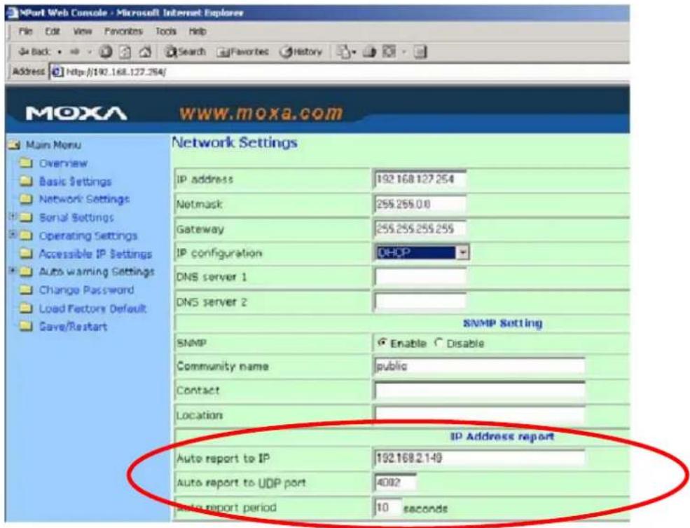
And then you can develop your own programs to receive this information from the NPort. Here is NPort's Auto IP Report Protocol. We provide an example for you to easily develop your own programs. You can find this example on Moxa's website.
Auto IP Report Format
| “Moxa”, 4 bytes | Info[0] Info[1] ... Info[n] |
Info [n]
| Field | ID | Length | Data |
| Length 1 1 | Variable, Length is “Length Field” | ||
ID List
| ID Value | Description Length | Note | |
| 1 | Server Name | Variable | ASCII char |
| 2 | Hardware ID | 2 | Little-endian |
| 3 | MAC Address | 6 | 6 bytes MAC address. If the MAC address is "00-90-E8-01-02-03", the MAC[0] is 0, MAC[1] is 0x90(hex), MAC[2] is 0xE8(hex), and so on. |
| 4 | Serial Number 4, DWORD | Little-endian | |
| 5 | IP Address | 4, DWORD | Little-endian |
| 6 | Netmask | 4, DWORD | Little-endian |
| 7 | Default Gateway | 4, DWORD | Little-endian |
| 8 | Firmware Version | 4, DWORD | Little-endianVer1.3.4= 0x0103040 |
| 9 | AP ID | 4, DWORD | Little-endian |
- NPort 5600 Series User's Manual
- Copyright Notice
- Trademarks
- Disclaimer
- Technical Support Contact Information
- www.moxa.com/support
- Chapter 1 Introduction....1-1
- Chapter 2 Getting Started....2-1
- Chapter 3 Initial IP Address Configuration....3-1
- Chapter 4 Choosing the Proper Operation Mode....4-1
- Chapter 5 Web Console Configuration ....5-1
- Chapter 6 Configuring NPort Administrator....6-1
- Appendix A Pinouts and Cable Wiring....A-1
- Appendix B Well Known Port Numbers ...... B-1
- Overview
- Package Checklist
- Standard Accessories
- Optional Accessories
- Product Features
- Product Specifications
- LAN
- Optical Fiber
- NPort 5610 Serial Interface
- NPort 5630 Serial Interface
- NPort 5650 Serial Interface
- Power Line Protection
- Advanced Built-in Features
- Serial Communication Parameters
- Software Features
- Power Requirements
- Mechanical
- Environment
- Regulatory Approvals
- Panel Layout
- Connecting the Hardware
- Wiring Requirements
- ATTENTION
- Safety First!
- Wiring Caution!
- Temperature Caution!
- Connecting NPort 5610/30/50-16/8's Power
- Connecting NPort 5610-16/8-48V's Power
- Grounding NPort 5610-16/8-48V
- Connecting to the Network
- Connecting to a Serial Device
- LED Indicators
- Link Indicator on the Rear Panel of NPort 5650 Fiber Model
- Real Time Clock
- Adjustable Pull High/low Resistors for the RS-485 Port
- Initializing NPort's IP Address
- Factory Default IP Address
- Default IP address: 192.168.127.254
- LCM Display
- Basic Operation
- Where
- Detailed Menu Options
- NPort Administration Suite
- ARP
- Telnet Console
- Choosing the Proper Operation Mode
- Real COM Mode
- TCP Server Mode
- TCP Client Mode
- UDP Mode
- Pair Connection Mode
- Reverse Telnet Mode
- Disabled Mode
- RFC2217 Mode
- PPP Mode
- Opening Your Browser
- Basic Settings
- Time
- Console
- Network Settings
- SNMP Settings
- IP Address Report
- Serial Settings
- Serial Parameters
- Operating Settings
- Max. connection 1:
- Max connection 2 to 4:
- Pair Connection Master Mode
- Pair Connection Slave Mode
- Accessible IP Settings
- PPP User Table
- Auto Warning Settings
- Mail Server
- SNMP Trap Server
- Event Type
- Cold start
- Warm start
- Authentication failure
- IP address changed
- Password changed
- DCD changed
- DSR changed
- Monitor
- Monitor Line
- Monitor Async
- Monitor Async-Settings
- Change Password
- Load Factory Defaults
- Installing NPort Administrator
- Configuration
- Broadcast Search
- Unlock Password Protection
- Lock
- Unlock
- Blank
- Fixed
- Lock Fixed
- Unlock Fixed
- Configuring NPort 5600
- Upgrading Firmware
- Export/Import
- Click Monitor.
- Select Add Target.
- Check the NPort you would like to Monitor, and then click OK.
- Port Monitor
- COM Mapping
- On-line COM Mapping
- Fast Flush (only flush local buffer)
- IP Location
- What is IP Serial Library?
- Why Use IP Serial Library?
- How to install IP Serial Library?
- □ Port Pinout Diagrams
- □ Cable Wiring Diagrams
- Port Pinout Diagrams
- Cable Wiring Diagrams
- Serial Cables for NPort 5630 (RS-422/4-wire RS-485)
- Serial Cables for NPort 5630 (2-wire RS-485)
- Serial Cables for NPort 5650 (2-wire RS-485)
- Pin Assignments for DB9 and DB25 Connectors
Brand : Moxa
Model : NPort 5630-16
Category : Server