
Granit 1280i - Barcode Reader HONEYWELL - Free user manual and instructions
Find the device manual for free Granit 1280i HONEYWELL in PDF.


| Product Type | Barcode Reader |
| Brand | Honeywell |
| Model | Granit 1280i |
| Dimensions (approx.) | 200 mm x 70 mm x 100 mm |
| Weight (approx.) | 200 g |
| Power Source | Rechargeable Li-ion battery or corded |
| Battery Runtime (approx.) | Up to 14 hours |
| Ingress Protection | IP65 |
| Drop Specification | Withstands multiple drops from 2 m onto concrete |
| Scanning Technology | Imager (1D/2D) |
| Scanning Range (typical) | Up to 50 cm for 1D codes |
| Interfaces | USB, RS232, Keyboard Wedge |
| Laser Safety Class | Class 2 (IEC 60825-1) |
| Operating Temperature | -20°C to 50°C |
| Maintenance | Clean lens with a soft, dry cloth |
| Spare Parts Available | Replacement cables, batteries, and scannable covers |
| Repairability | User-replaceable battery and interface cable |
| Compliance Certifications | CE, FCC, RoHS |
Frequently Asked Questions - Granit 1280i HONEYWELL
User questions about Granit 1280i HONEYWELL
0 question about this device. Answer the ones you know or ask your own.
Ask a new question about this device
Download the instructions for your Barcode Reader in PDF format for free! Find your manual Granit 1280i - HONEYWELL and take your electronic device back in hand. On this page are published all the documents necessary for the use of your device. Granit 1280i by HONEYWELL.
USER MANUAL Granit 1280i HONEYWELL
Industrial Full Range Laser Scanner
User's Guide
Disclaimer
Honeywell International Inc. ("HII") reserves the right to make changes in specifications and other information contained in this document without prior notice, and the reader should in all cases consult HII to determine whether any such changes have been made. The information in this publication does not represent a commitment on the part of HII.
HII shall not be liable for technical or editorial errors or omissions contained herein; nor for incidental or consequential damages resulting from the furnishing, performance, or use of this material.
This document contains proprietary information that is protected by copyright. All rights are reserved. No part of this document may be photocopied, reproduced, or translated into another language without the prior written consent of HII.
© 2014 Honeywell International Inc. All rights reserved.
Web Address: www.honeywellaidc.com
Granit is a trademark or registered trademark of Honeywell International Inc.
Microsoft® Windows®, Windows NT®, Windows 2000, Windows ME, Windows XP, and the Windows logo are trademarks or registered trademarks of Microsoft Corporation.
Other product names or marks mentioned in this document may be trademarks or registered trademarks of other companies and are the property of their respective owners.
Product Agency Compliance - Granit 1280i
USA
FCC Part 15 Subpart B Class B
This device complies with part 15 of the FCC Rules. Operation is subject to the following two conditions:
- This device may not cause harmful interference.
- This device must accept any interference received, including interference that may cause undesired operation.
This equipment has been tested and found to comply with the limits for a Class B digital device pursuant to part 15 of the FCC Rules. These limits are designed to provide reasonable protection against harmful interference in a residential installation. This equipment generates, uses, and can radiate radio frequency energy and, if not installed and used in accordance with the instructions, may cause harmful interference to radio communications. However, there is no guarantee that interference will not occur in a particular installation. If this equipment does cause harmful interference to radio or television reception, which can be determined by turning the equipment off and on, the user is encouraged to try to correct the interference by one or more of the following measures:
- Reorient or relocate the receiving antenna.
- Increase the separation between the equipment and receiver.
- Connect the equipment into an outlet on a circuit different from that to which the receiver is connected.
- Consult the dealer or an experienced radio or television technician for help.
If necessary, the user should consult the dealer or an experienced radio/television technician for additional suggestions. The user may find the following booklet helpful: "Something About Interference." This is available at FCC local regional offices. Honeywell is not responsible for any radio or television interference caused by unauthorized modifications of this equipment or the substitution or attachment of connecting cables and equipment other than those specified by Honeywell. The correction is the responsibility of the user.
Use only shielded data cables with this system. This unit has been tested with cables less than 3 meters. Cables greater than 3 meters may not meet class B performance.
Caution: Any changes or modifications made to this equipment not expressly approved by Honeywell may void the FCC authorization to operate this equipment.

TÜV-R Statement
TÜV R listed: UL 60950-1, Second Edition and CSA C22.2 No.60950-1-07, Second Edition.
Canada
Industry Canada ICES-003
This Class B digital apparatus complies with Canadian ICES-003. Operation is subject to the following conditions:
- This device may not cause harmful interference.
- This device must accept any interference received, including interference that may cause undesired operation.
TÜV R listed: UL 60950-1, Second Edition and CSA C22.2 No.60950-1-07, Second Edition.
Europe

The CE marking indicates compliance with the following directives:
• 2004/108/EC EMC
• 2011/65/EU RoHS (Recast)
In addition, complies to 2006/95/EC Low Voltage Directive, when shipped with recommended power supply. European contact:
Hand Held Products Europe B.V.
Nijverheidsweg 9-13
5627 BT Eindhoven
The Netherlands
Honeywell International Inc. shall not be liable for use of our product with equipment (i.e., power supplies, personal computers, etc.) that is not CE marked and does not comply with the Low Voltage Directive.
Honeywell Scanning & Mobility Product Environmental Information
Refer to www.honeywellaidc.com/environmental for the RoHS / REACH / WEEE information.
Australia/NZ
C-Tick Statement

Conforms to AS/NZS 3548 EMC requirement
Mexico


Conforms to NOM-019.
Japan

VCCI: V-3, Technical Requirements, Class B ITE.
This product meets Korean agency approval.
Taiwan
If the following label is attached to your product, the product meets Taiwan agency approval:

BSMI Standard: CNS13438, CNS14336
Customs Union approval
International
CB Scheme
Certified to CB Scheme IEC 60950-1, Second Edition.
Laser Safety Statement
If the following label is attached to your product, it indicates the product contains a laser engine or laser aimer:

This device has been tested in accordance with and complies with IEC60825-1 ed2 (2007). Complies with 21 CFR 1040.10 and 1040.11, except for deviations pursuant to Laser Notice No. 50, dated June 24, 2007.
LASER LIGHT, DO NOT STARE INTO BEAM, CLASS 2 LASER PRODUCT, 1.0 mW MAX OUTPUT: 650nM.
Caution: Use of controls or adjustments or performance of procedures other than those specified herein may result in hazardous radiation exposure.
Patents
For patent information, please refer to www.honeywellaidc.com/patents.
Solids and Water Protection
The Granit 1280i has a rating of IP65, totally protected against dust and protected against low pressure water jets.
Warning

To reduce the possibility of heat-related injuries, avoid touching sections of the scanner that feel warm.
Required Safety Labels
Granit 1280i Scanner

Table of Contents
Chapter 1 - Getting Started
About This Manual....1-1
Unpacking Your Device 1-1
Connecting the Device....1-1
Reading Techniques....1-2
Cyber Security Settings 1-2
Setting Custom Defaults 1-2
Resetting the Custom Defaults 1-2
Chapter 2 - Programming the Interface
Introduction 2-1
Programming the Interface - Plug and Play 2-1
RS232 Serial Port 2-1
OPOS Mode 2-1
Verifone® Ruby Terminal Default Settings....2-2
Gilbarco® Terminal Default Settings 2-2
Honeywell Bioptic Aux Port Configuration 2-2
Datalogic™ Magellan® Aux Port Configuration....2-2
NCR Bioptic Aux Port Configuration 2-3
Wincor Nixdorf Terminal Default Settings 2-3
Wincor Nixdorf Beetle™ Terminal Default Settings 2-3
RS232 Modifiers 2-4
RS232 Baud Rate 2-4
RS232 Word Length: Data Bits, Stop Bits, and Parity 2-5
RS232 Handshaking 2-6
RS232 Timeout 2-7
XON/XOFF 2-7
ACK/NAK 2-8
Communication Timeout 2-8
NAK Retries 2-9
Support BEL/CAN in ACK/NAK....2-9
RS232 Defaults 2-9
NCR Modifiers....2-9
NCR ACK/NAK....2-9
Block Check Character 2-10
NCR Prefix 2-10
NCR Suffix 2-10
NCR Prefix/Suffix 2-10
NCR NOF (Not-on-File) Error....2-11
Scanner to Bioptic Communication....2-11
Scanner-Bioptic Packet Mode....2-11
Chapter 3 - Input/Output Settings
Power Save Mode....3-1
Power Up Beeper....3-1
Beep on BEL Character....3-2
Good Read and Error Indicators....3-2
Beeper – Good Read....3-2
Beeper Volume – Good Read....3-2
Beeper Pitch – Good Read....3-3
Beeper - Transmit Order 3-3
Vibrate – Good Read 3-3
Beeper Pitch – Error 3-4
Beeper Duration – Good Read 3-4
Number of Beeps – Good Read ....3-5
Number of Beeps - Error 3-5
Beeper Volume Max 3-5
Laser Aimer 3-5
Laser Aimer - Scanning Pattern.... 3-5
Laser Aimer - Scanning Duration 3-6
Laser Aimer - Good Read Pattern 3-6
Laser Aimer - Good Read Duration 3-7
Aimer Delay 3-7
LED Indicators 3-8
LED Settings....3-8
Good Read Delay 3-9
User-Specified Good Read Delay....3-9
Out-Of-Stand Settings 3-9
Out-of-Stand Defaults 3-9
Presentation Mode....3-10
Manual Activation Mode 3-10
End Manual Activation After Good Read 3-10
Manual Activation Laser Timeout - Trigger Settings....3-11
Reread Delay....3-11
User-Specified Reread Delay 3-11
CodeGate ® 3-12
Character Activation Mode 3-12
Activation Character 3-12
End Character Activation After Good Read....3-13
Character Activation Timeout 3-13
Character Deactivation Mode 3-13
Deactivation Character 3-14
Centering 3-14
Blinky Mode 3-15
Laser Scan Angle 3-15
Decode Security 3-16
Continuous Scan Mode 3-16
Output Sequence Overview....3-16
Output Sequence Editor 3-16
To Add an Output Sequence 3-16
Other Programming Selections.... 3-17
Output Sequence Editor 3-18
Sequence Timeout....3-18
Sequence Match Beeper 3-18
Partial Sequence 3-19
Require Output Sequence 3-19
No Read 3-20
Chapter 4 - Data Editing
Prefix/Suffix Overview 4-1
To Add a Prefix or Suffix: 4-1
To Clear One or All Prefixes or Suffixes....4-2
To Add a Carriage Return Suffix to All Symbologies 4-2
Prefix Selections 4-2
Suffix Selections 4-2
Function Code Transmit 4-3
Communication Check Character....4-3
Intercharacter, Interfunction, and Intermessage Delays....4-3
Intercharacter Delay 4-4
User Specified Intercharacter Delay 4-4
Interfunction Delay 4-4
Intermessage Delay 4-5
Chapter 5 - Data Formatting
Data Format Editor Introduction 5-1
Add a Data Format 5-1
Other Programming Selections.... 5-2
Terminal ID Table 5-3
Data Format Editor Commands....5-3
Move Commands....5-6
Search Commands....5-7
Miscellaneous Commands....5-9
Data Formatter 5-11
Data Format Non-Match Error Tone....5-12
Primary/Alternate Data Formats 5-12
Single Scan Data Format Change....5-13
Chapter 6 - Symbologies
All Symbologies....6-1
Message Length Description 6-1
Codabar....6-2
Codabar Concatenation....6-3
Code 39 6-5
Code 32 Pharmaceutical (PARAF)....6-6
Full ASCII....6-7
Code 39 Code Page 6-7
Interleaved 2 of 5....6-8
Matrix 2 of 5....6-9
NEC 2 of 5....6-11
Code 93....6-12
Code 93 Code Page 6-13
Straight 2 of 5 Industrial (three-bar start/stop)....6-14
Straight 2 of 5 IATA (two-bar start/stop)....6-15
Code 11....6-16
Code 128....6-17
with Extended Coupon Code 6-28
UPC-A/Code 128 Coupon Code Output....6-28
UPC-A Number System 5 Addenda Required....6-29
Coupon GS1 DataBar Output....6-30
UPC-E0 6-31
EAN/JAN-13 6-34
Convert UPC-A to EAN-13 6-34
ISBN Translate 6-40
ISSN Translate 6-41
EAN/JAN-8 6-42
MSI 6-44
Plessey Code 6-46
GS1 DataBar Omnidirectional 6-47
GS1 DataBar Limited 6-48
GS1 DataBar Expanded 6-49
Trioptic Code 6-50
GS1 Emulation 6-50
China Post (Hong Kong 2 of 5)....6-51
Chapter 7 - Utilities
To Add a Test Code I.D. Prefix to All Symbologies.... 7-1
Show Software Revision....7-1
Show Data Format....7-1
Test Menu....7-1
TotalFreedom 7-1
Application Plug-Ins (Apps) 7-2
EZConfig-Scanning Introduction....7-2
Installing EZConfig-Scanning from the Web 7-3
Resetting the Factory Defaults 7-3
Chapter 8 - Serial Programming Commands
Conventions....8-1
Menu Command Syntax 8-1
Query Commands 8-1 Responses 8-2
Serial Trigger Commands....8-3 Read Time-Out....8-3
Resetting the Custom Defaults....8-3
Menu Commands 8-4
Chapter 9 - Product Specifications
Granit 1280i Industrial Corded Scanner Product Specifications.... 9-1
Depth of Field Charts....9-2
Typical Performance 9-2
Guaranteed Performance 9-2
9-3
Standard Connector Pinouts 9-4
Serial Output....9-4
Chapter 10 - Maintenance
Repairs 10-1
Maintenance 10-1
Cleaning the Scanner 10-1
Cleaning the Window....10-1
Inspecting Cords and Connectors 10-1
Replacing Cables 10-1
Replacing an Interface Cable 10-2
Troubleshooting....10-2
Chapter 11 - Customer Support
Technical Assistance....11-1
Product Service and Repair....11-1
Appendix A - Reference Charts
Symbology Charts ......A-1
Linear Symbologies....A-1
Postal Symbologies....A-2
ASCII Conversion Chart (Code Page 1252)......A-2
Lower ASCII Reference Table....A-3
ISO 2022/ISO 646 Character Replacements ......A-7
Unicode Key Maps ......A-9
Getting Started
About This Manual
This User's Guide provides installation and programming instructions for the Granit 1280i corded industrial scanners. Product specifications, dimensions, warranty, and customer support information are also included.
Honeywell bar code scanners are factory programmed for the most common terminal and communications settings. If you need to change these settings, programming is accomplished by scanning the bar codes in this guide.
An asterisk (*) next to an option indicates the default setting.
Unpacking Your Device
After you open the shipping carton containing the product, take the following steps:
- Check for damage during shipment. Report damage immediately to the carrier who delivered the carton.
• Make sure the items in the carton match your order. - Save the shipping container for later storage or shipping.
Connecting the Device
- Turn off power to the terminal/computer.
- Connect the appropriate interface cable to the scanner.
Note: For the scanner to work properly, you must have the correct cable for your type of terminal/computer.

- Make sure the cable is pushed tightly into the scanner. Loosen the locking plate and slide it over the base of the cable connector to lock the cable in place. Tighten the screw.
- Plug the serial connector into the serial port on your computer. Tighten the two screws to secure the connector to the port.
- Once the scanner has been fully connected, power up the computer.
- Plug in the AC adapter, if applicable.
This interface programs 9600 baud, 8 data bits, no parity, and 1 stop bit.
Reading Techniques
The Granit 1280i scanner has a bright red scanning line that corresponds to the scanner's horizontal field of view.

The scanning line is smaller when the scanner is closer to the code and larger when it is farther from the code. Symbologies with smaller bars or elements (mil size) should be read closer to the unit. Symbologies with larger bars or elements (mil size) should be read farther from the unit. To read single or multiple symbols (on a page or on an object), hold the scanner at an appropriate distance from the target, pull the trigger, and center the scanning line on the symbol. If the code being scanned is highly reflective (e.g., laminated), it may be necessary to tilt the code up 15irc to 18irc to prevent unwanted reflection.
Cyber Security Settings
Honeywell scanners have additional settings aimed at preventing cyber attacks. You may want to restrict the ability to program your device with menu codes or serial commands, or you may want to disable firmware upgrades to your device. Honeywell's Cyber Security settings allow you to secure your device by restricting these features. Please contact the nearest technical support office (see Technical Assistance on page 11-1) for further information.
Setting Custom Defaults
You have the ability to create a set of menu commands as your own, custom defaults. To do so, scan the Set Custom Defaults bar code below before scanning the menu commands for your custom defaults. If a menu command requires scanning numeric codes from the back cover, then a Save code, that entire sequence will be saved to your custom defaults. When you have entered all the commands you want to save for your custom defaults, scan the Save Custom Defaults bar code.

MNUCDP
Set Custom Defaults

MNUCDS.
Save Custom Defaults
You may have a series of custom settings and want to correct a single setting. To do so, just scan the new setting to overwrite the old one. For example, if you had previously saved the setting for Beeper Volume at Low to your custom defaults, and decide you want the beeper volume set to High, just scan the Set Custom Defaults bar code, then scan the Beeper Volume High menu code, and then Save Custom Defaults. The rest of the custom defaults will remain, but the beeper volume setting will be updated.
Resetting the Custom Defaults
If you want the custom default settings restored to your scanner, scan the Activate Custom Defaults bar code below. This is the recommended default bar code for most users. It resets the scanner to the custom default settings. If there are no custom defaults, it will reset the scanner to the factory default settings. Any settings that have not been specified through the custom defaults will be defaulted to the factory default settings.

DEFAULT.
Activate Custom Defaults
Programming the Interface
Introduction
This chapter describes how to program your system for the desired interface.
Programming the Interface - Plug and Play
Plug and Play bar codes provide instant scanner set up for commonly used interfaces.
Note: After you scan one of the codes, power cycle the host terminal to have the interface in effect.
RS232 Serial Port
The RS232 Interface bar code is used when connecting to the serial port of a PC or terminal. The following RS232 Interface bar code also programs a carriage return (CR) and a line feed (LF) suffix, baud rate, and data format as indicated below. It also changes the trigger mode to manual.
Option Setting
Baud Rate 9600 bps
Data Format 8 data bits, no parity bit, 1 stop bit

PAP232
RS232 Interface
OPOS Mode
The following bar code configures your engine for OPOS (OLE for Retail Point of Sale) by modifying the following OPOS-related settings:
| Option Setting | |
| Interface RS232 | |
| Baud Rate 38400 | |
| RS232 Handshaking Flow Control, No | Timeout |
| XON/XOFF Off | |
| ACK/NAK Off | |
| Data Bits, Stop Bits, and Parity 8 Data, 1 Stop, Parity None | |
| Prefix/Suffix | Clear All Prefixes and Suffixes |
| Add Code ID and AIM ID Prefix | |
| Add CR Suffix | |
| Intercharacter Delay Off | |
| Symbologies Enable UPC-A with check digit and number system | |

PAPOPS
OPOS Mode
Verifone® Ruby Terminal Default Settings
Scan the following Plug and Play code to program the scanner for a Verifone Ruby terminal. This bar code sets the baud rate to 1200 bps and the data format to 8 data bits, no parity bit, 1 stop bit. It also adds a line feed (LF) suffix and programs the following prefixes for each symbology:
Symbology Prefix
UPC-A A
UPC-E A
EAN-8 FF
EAN-13 F

PAPRBY
Verifone Ruby Settings
Gilbarco ® Terminal Default Settings
Scan the following Plug and Play code to program the scanner for a Gilbarco terminal. This bar code sets the baud rate to 2400 bps and the data format to 7 data bits, even parity, 2 stop bits. It also adds a carriage return (CR) suffix and programs the following prefixes for each symbology:
Symbology Prefix
UPC-A A
UPC-E E0
EAN-8 FF
EAN-13 F

PAPGLB
Gilbarco Settings
Honeywell Bioptic Aux Port Configuration
Scan the following Plug and Play code to program the scanner for a Honeywell bioptic scanner auxiliary port configuration. This bar code sets the baud rate to 38400 bps and the data format to 8 data bits, no parity, 1 stop bit.

PAPBIO.
Honeywell Bioptic Settings
Datalogic™ Magellan® Aux Port Configuration
Scan the following Plug and Play code to program the scanner for a Datalogic Magellan auxiliary port configuration. This bar code sets the baud rate to 9600 bps and the data format to 8 data bits, no parity, 1 stop bit.

PAPMAG.
Datalogic Magellan Settings
NCR Bioptic Aux Port Configuration
Scan the following Plug and Play code to program the scanner for an NCR bioptic scanner auxiliary port configuration. The following prefixes are programmed for each symbology:
| Symbology Prefix Symbology Prefix | |
| UPC-A A Code 39 a | |
| UPC-E E0 Code 128 f | |
| EAN-8 FF Interleaved 2 of 5 b | |
| EAN-13 F All other bar | B3 codes |
PAPNCR
NCR Bioptic Settings
Wincor Nixdorf Terminal Default Settings
Scan the following Plug and Play code to program the scanner for a Wincor Nixdorf terminal. This bar code sets the baud rate to 9600 bps and the data format to 8 data bits, no parity, 1 stop bit.

PAPWNX
Wincor Nixdorf Terminal Settings
Wincor Nixdorf Beetle™ Terminal Default Settings
Scan the following Plug and Play code to program the scanner for a Wincor Nixdorf Beetle terminal. The following prefixes are programmed for each symbology:
| Symbology Prefix Symbology P | efix | ||
| Code 128 K EAN-13 A | |||
| Code 93 L | GS1-128 | P | |
| Codabar | N | Interleaved 2 of 5 I | |
| UPC-A A0 | Plessey O | ||
| UPC-E | C | Straight 2 of 5 IATA | H |
| EAN-8 B All other bar codes | M | ||

PAPBTL
Wincor Nixdorf Beetle Settings
RS232 Modifiers
RS232 Baud Rate
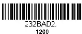
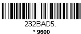
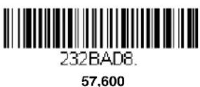
Baud Rate sends the data from the scanner to the terminal at the specified rate. The host terminal must be set for the same baud rate as the scanner. Default = 9600.







RS232 Word Length: Data Bits, Stop Bits, and Parity
Data Bits sets the word length at 7 or 8 bits of data per character. If an application requires only ASCII Hex characters 0 through 7F decimal (text, digits, and punctuation), select 7 data bits. For applications that require use of the full ASCII set, select 8 data bits per character. Default = 8.
Stop Bits sets the stop bits at 1 or 2. Default = 1.
Parity provides a means of checking character bit patterns for validity.
Default = None.

232WRD3
7 Data, 1 Stop, Parity Even

232WRDO
7 Data, 1 Stop, Parity None

232WRD6
7 Data, 1 Stop, Parity Odd

232WRD4
7 Data, 2 Stop, Parity Even

232WRD1
7 Data, 2 Stop Parity None

232WRD7
7 Data, 2 Stop, Parity Odd

232WRD5
8 Data, 1 Stop, Parity Even

232WRD2
* 8 Data, 1 Stop, Parity None

232WRD8
8 Data, 1 Stop, Parity Odd

232WRD9
7 Data, 1 Stop, Parity Space

232WRD10
7 Data, 2 Stop, Parity Space

232WRD11
8 Data, 1 Stop, Parity Space

232WRD12
7 Data, 1 Stop, Parity Mark

232WRD13
7 Data, 2 Stop, Parity Mark

232WRD14
8 Data, 1 Stop, Parity Mark
RS232 Handshaking
RS232 Handshaking allows control of data transmission from the scanner using software commands from the host device.
RTS/CTS Off: RTS/CTS is turned off so no data flow control is used, but RTS is still active.
RTS/CTS Off, RTS Inactive: RTS/CTS is turned off so no data flow control is used and RTS is inactive.
Flow Control, No Timeout: The scanner asserts RTS when it has data to send, and will wait indefinitely for CTS to be asserted by the host.
Character-Based Flow Control, No Timeout: The scanner asserts RTS when it has a character to send, and will wait indefinitely for CTS to be asserted by the host
Two-Direction Flow Control: The scanner asserts RTS when it is OK for the host to transmit. The host asserts CTS when it is OK for the device to transmit.
Flow Control with Timeout: The scanner asserts RTS when it has data to send and waits for a delay (see RS232 Timeout on page 2-7) for CTS to be asserted by the host. If the delay time expires and CTS is not asserted, the device transmit buffer is cleared and scanning may resume.
Character-Based Flow Control with Timeout: The scanner asserts RTS when it has a character to send and waits for a delay (see RS232 Timeout on page 2-7) for CTS to be asserted by the host. If the delay time expires and CTS is not asserted, the device transmit buffer is cleared and scanning may resume.
Default = RTS/CTS Off.

232CTSO
* RTS/CTS Off

232CTS10.
* RTS/CTS Off, RTS Inactive

232CTS1
Flow Control, No Timeout

232CTS7
Character-Based Flow Control, No Timeout

232CTS2
Two-Direction Flow Control

232CTS3
Flow Control with Timeout

232CTS9
Character-Based Flow Control
with Timeout
RS232 Timeout
When using Flow Control with Timeout, you must program the length of the delay you want to wait for CTS from the host. Set the length (in milliseconds) for a timeout by scanning the bar code below, then setting the timeout (from 1-65535 milliseconds) by scanning digits from the inside back cover, then scanning Save.

232DEL
RS232 Timeout
XON/XOFF
Standard ASCII control characters can be used to tell the scanner to start sending data (XON/XOFF On) or to stop sending data (XON/XOFF Off). When the host sends the XOFF character (DC3, hex 13) to the scanner, data transmission stops. To resume transmission, the host sends the XON character (DC1, hex 11). Data transmission continues where it left off when XOFF was sent. Default = XON/XOFF Off.

232XON1
XON/XOFF On

232XONO
* XON/XOFF Off
ACK/NAK
After transmitting data, the scanner waits for an ACK character (hex 06) or a NAK character (hex 15) response from the host. If ACK is received, the communications cycle is completed and the scanner looks for more bar codes. If NAK is received, the last set of bar code data is retransmitted and the scanner waits for ACK/NAK again. Turn on the ACK/NAK protocol by scanning the ACK/NAK On bar code below. To turn off the protocol, scan ACK/NAK Off. Default = ACK/NAK Off.

232ACK1
ACK/NAK On

232ACKD
* ACK/NAK Off
Communication Timeout
This allows you to set the length (in milliseconds) for a timeout for the host ACK/NAK response. Scan the bar code below, then set the timeout (from 1-65535 milliseconds) by scanning digits from the Programming Chart, then scanning Save. Default = 2000 ms.

232DLK
Communication Timeout
Timeout Retries
This setting limits the number of Communication Timeout retries. If the Timeout Retries is set to 0, the transmission is terminated after the initial Communication Timeout. Scan the bar code below, then set the number of retries (from 0-255) by scanning digits from the Programming Chart, then scanning Save. (5 is the recommended setting.) Default = 0.

HSTRTY
Timeout Retries
Communication Timeout Beeper
This selection programs the scanner to issue an error beep when a communication timeout has occurred. The error beep sound is programmed using Number of Beeps - Error (page 3-5). Default = On.

HSTTOAO
Off

HSTTOA1
* On
NAK Retries
This selection limits the number of NAK retries that can occur in ACK/NAK mode. Scan the bar code below, then set the number of retries (from 0-255) by scanning digits from the Programming Chart, then scanning Save. (5 is the recommended setting.) Default = 0, or disabled.

HSTRTN.
NAK Retries
Support BEL/CAN in ACK/NAK
This protocol responds to

BELCAN1
BEL/CAN On

BELCANO
* BEL/CAN Off
RS232 Defaults
If you want the custom RS232 default settings restored to your scanner, scan the RS232 Defaults bar code below. This resets the scanner to the custom default settings (see Setting Custom Defaults on page 1-2). If there are no custom defaults, it will reset the scanner to the factory default settings. Any settings that have not been specified through the custom defaults will be restored to the factory default settings.

232DFT
RS232 Defaults
NCR Modifiers
NCR ACK/NAK
This is an NCR communication protocol for ACK/NAK processing. Default = NCR ACK/NAK Off.

NCRACKD
* NCR ACK/NAK Off

NCRACK1
NCR ACK/NAK On
Block Check Character
When this selection is set to Transmit, the NCR Block Check Character (BCC) is expected with incoming messages and transmitted with outgoing messages. Default = Transmit.

NCRBCC1.
* Transmit

NCRBCCO.
Don't Transmit
NCR Prefix
This selection allows you to program an NCR-specific prefix. Refer to the ASCII Conversion Chart (Code Page 1252), page A-2 to find the hex equivalent for the characters you want for the NCR prefix (typically, 02 for STX). Scan the bar code below, then set the hex number (from 0-FF) by scanning digits from the Programming Chart, then scanning Save. Default = 0.

NCRPR2.
NCR Prefix
NCR Suffix
This selection allows you to program an NCR-specific suffix. Refer to the ASCII Conversion Chart (Code Page 1252), page A-2 to find the hex equivalent for the characters you want for the NCR suffix (typically, 03 for ETX). Scan the bar code below, then set the hex number (from 0-FF) by scanning digits from the Programming Chart, then scanning Save. Default = 0.

NCRSF2.
NCR Suffix
NCR Prefix/Suffix
When set to Transmit, both the NCR prefix and suffix are transmitted with bar codes. Usually, prefixes and suffixes are programmed using the Data Editing selections (see Data Editing beginning on page 4-1), however, the following commands override any other prefix/suffix settings. Default = Don't Transmit.

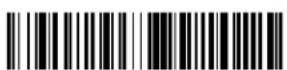
NCRBCP1
Transmit
NCRBCPO.
* Don't Transmit
NCR NOF (Not-on-File) Error
A scanner receives an NOF (Not on File) command from the POS whenever it cannot cross-reference the bar code to a price parameter. When set to On, the error tone sounds (set via Number of Beeps – Error, page 3-5) for an NOF, and disables the scanner while the cashier looks up the price manually. When set to Off, no sound is emitted for an NOF. Default = Off.


Scanner to Bioptic Communication
The following settings are used to set up communication between Honeywell scanners and bioptic scanners.
Note: The scanner's baud rate must be set to 38400 and the RS232 timeout must be set to 3000 in order to communicate with a bioptic scanner. See "RS232 Modifiers" on page 2-4, and RS232 Timeout on page 2-7 for further information.
Scanner-Bioptic Packet Mode
Packet Mode On must be scanned to set the scanner's format so it is compatible with a bioptic scanner. Default = Packet Mode Off.


Power Save Mode
Power Save Mode allows you to automatically set the conditions under which the scanner idles, sleeps, and wakes up. When Off is selected, no power saving is used and the scanner remains powered on until the trigger is pressed.
When Sleep Mode is selected, the scanner goes into sleep mode (powered off) after the time interval set using Power Save Mode Timeout (page 3-1), during which there is no activity. This provides significant power savings over the Off setting.
When Hibernate Mode is selected, the scanner goes into idle mode after the time interval set using Power Save Mode Timeout (page 3-1), during which there is no activity. After the same time interval has elapsed with no activity while the scanner is in idle mode, the scanner goes into sleep mode (powered off). This provides additional power savings over the Sleep Mode setting, but the scanner takes longer to wake up.
Default = Off.

PWRMODO.
* Off

PWRMOD1.
Sleep Mode Only
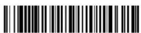
PWRMOD2.
Hibernate Mode
Power Save Mode Timeout
Use this selection to set a timeout (in seconds) for the scanner when using Power Save Mode. When this time has elapsed with no activity, the scanner will enter the Power Save Mode selected. After scanning the Power Save Mode Timeout bar code, set the timeout duration (from 0-65535 seconds) by scanning digits on the Programming Chart inside the back cover, then scanning Save. Default = 600 seconds.

PWRLPT.
Power Save Mode Timeout
Power Up Beeper
The scanner can be programmed to beep when it's powered up. Scan the Off bar code(s) if you don't want a power up beep. Default = Power Up Beeper On - Scanner.

BEPPWRO.
Power Up Beeper Off - Scanner
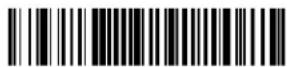
BEPPWR1.
* Power Up Beeper On - Scanner
Beep on BEL Character
You may wish to force the scanner to beep upon a command sent from the host. If you scan the Beep on BEL On bar code below, the scanner will beep every time a BEL character is received from the host. Default = Beep on BEL Off.

BELBEPO
*Beep on BEL Off

BELBEP1
Beep on BEL On
Good Read and Error Indicators
Beeper – Good Read
The beeper may be programmed On or Off in response to a good read. Turning this option off only turns off the beeper response to a good read indication. All error and menu beeps are still audible. Default = Beeper - Good Read On.

BEPBEPO.
Beeper - Good Read Off

BEPBEP1.
* Beeper - Good Read On
Beeper Volume – Good Read
The beeper volume codes modify the volume of the beep the scanner emits on a good read. Default = High.

BEPLVL1
Low

BEPLVL2
Medium

BEPLVL3.
* High

Beeper Pitch – Good Read
The beeper pitch codes modify the pitch (frequency) of the beep the scanner emits on a good read. Default = Medium.

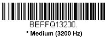

Beeper - Transmit Order
The beeper transmit order determines when the good read beep occurs. The scanner can be set to emit the good read beep either before or after data transmission. Default = Before Transmission.

Vibrate – Good Read
The scanner vibrates once when a bar code is successfully read, and twice when a programming bar code is successfully read. When a programming bar code is unsuccessful, the scanner emits one long vibration (2 times the Vibrate Duration length). The trigger cannot be used again until the vibration has ended. Scan Vibrate - Good Read Off to keep the scanner from vibrating. This setting may be preferable if you need to scan multiple bar codes in succession and do not want to wait till the vibration has ended. Default = Vibrate - Good Read On.
Vibrate Duration
If you want to set the length for the good read vibration, scan the bar code below, then set the duration (from 100 - 2,000 milliseconds) by scanning digits from the inside back cover, then scanning Save. If you need to scan multiple bar codes in succession, you may wish to set a short duration time, since the trigger cannot be used until the vibration has ended. Default = 300 ms.

TFBDUR
Vibrate Duration
Beeper Pitch – Error
The beeper pitch codes modify the pitch (frequency) of the sound the scanner emits when there is a bad read or error. Default = Razz.

BEPFQ2100.
* Razz (100 Hz)

BEPFQ23250
Medium (3250 Hz)

BEPFQ24200
High (4200 Hz)
Beeper Duration – Good Read
The beeper duration codes modify the length of the beep the scanner emits on a good read. Default = Normal.

BEPBIPO
* Normal Beep

BEPBIP1
Short BeepShort Beep
Number of Beeps – Good Read
The number of beeps of a good read can be programmed from 1 - 9. The same number of beeps will be applied to the beeper and LED in response to a good read. For example, if you program this option to have five beeps, there will be five beeps and five LED flashes in response to a good read. The beeps and LED flashes are in sync with one another. To change the number of beeps, scan the bar code below and then scan a digit (1-9) bar code and the Save bar code on the Programming Chart inside the back cover of this manual. Default = 1.

BEPRPT.
Number of Good Read Beeps/LED Flashes
Number of Beeps - Error
The number of beeps and LED flashes emitted by the scanner for a bad read or error can be programmed from 1 - 9. For example, if you program this option to have five error beeps, there will be five error beeps and five LED flashes in response to an error. To change the number of error beeps, scan the bar code below and then scan a digit (1-9) bar code and the Save bar code on the Programming Chart inside the back cover of this manual. Default = 1.

BEPERR
Number of Error Beeps/LED Flashes
Beeper Volume Max
Scan the following bar code to set all error and good read beeps to the maximum volume. This feature also sets the Beeper Pitch – Good Read to the highest level.

PAPBLM
Beeper Volume Max
Laser Aimer
Laser Aimer - Scanning Pattern
To set the laser light pattern that appears when scanning a bar code, you must first enter an aimer delay (see Aimer Delay on page 3-7). Then scan one of the following bar codes to set a new scanning pattern.
Default = 10 Segment Line.

SCNGS10.
Laser Aimer - Scanning Pattern Off

SCNGSI1.
Laser Aimer - Scanning Laser Dot

Laser Aimer - Scanning Blinking Dot
Laser Aimer - Scanning
3 Segment Line

Laser Aimer - Scanning
5 Segment Line
* Laser Aimer - Scanning 10 Segment Line
Laser Aimer - Scanning Duration
Use the Laser Aimer - Scanning Duration bar code to specify how long you want the Laser Aimer - Scanning Pattern to remain on after the trigger is released. Scan the bar code below, then set the duration (from 0 - 65535 milliseconds) by scanning digits from the inside back cover, then scanning Save. Default = 0 ms.
Laser Aimer - Scanning Duration
Laser Aimer - Good Read Pattern
Once a bar code has been successfully read, you may want the laser light to remain on, but to display a different pattern than the scanning pattern. This gives the operator an additional visual indicator that the bar code was successfully read. Scan one of the bar codes below to program your device for a Good Read Pattern. Default = 10 Segment Line.

Laser Aimer - Good Read Pattern Off
Laser Aimer - Good Read
3 Segment Line
Laser Aimer - Good Read
5 Segment Line

LASGS15
* Laser Aimer - Good Read 10 Segment Line
Laser Aimer - Good Read Duration
Use the Laser Aimer - Good Read Duration bar code to specify how long you want the Laser Aimer - Good Read Pattern to remain on after a bar code has been successfully read. Scan the bar code below, then set the duration (from 0 - 65535 milliseconds) by scanning digits from the inside back cover, then scanning Save. Default = 0 ms.

LASGIT.
Laser Aimer - Good Read Duration
Aimer Delay
The aimer delay allows a delay time for the operator to aim the scanner before the bar code is scanned. Use these codes to set the time between when the trigger is pulled and when the bar code is scanned. During the delay time, the aiming light will appear, but scanning will not begin until the delay time is over. Default = Off.

SCNDLY200
200 milliseconds

SCNDLY400
400 milliseconds

SCNDLYO
* Off (no delay)
User-Specified Aimer Delay
If you want to set your own length for the duration of the delay, scan the bar code below, then set the time-out by scanning digits (0 - 4,000 ms) from the Programming Chart inside the back cover of this manual, then scan Save.

SCNDLY
Delay Duration
LED Indicators
The green and red LEDs can be programmed to be On or Off and at different brightness levels to indicate various scanner states. Use the following bar codes to program the LED indicators.
LED Settings
Default = Red LED On with Laser, Green LED On with Good Scan.
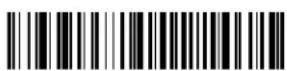
LEDFN10.
Red LED Off
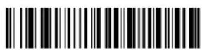
LEDFN20.
Green LED Off

LEDFN11.
Red LED On with Good Scan

LEDFN21.
* Green LED On with Good Scan

LEDFN12.
* Red LED On with Laser
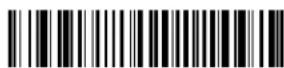
LEDFN22.
Green LED On with Laser

LEDFN14.
Red LED On when CodeGate
Disabled

LEDFN24.
Green LED On when CodeGate
Disabled

LEDFN1128.
Red LED On with CTS

LEDFN2128.
Green LED On with CTS
Good Read Delay
This sets the minimum amount of time before the scanner can read another bar code. Default = 0 ms (No Delay).

DLYGRDO.
* No Delay

DLYGRD500
Short Delay (500 ms)

DLYGRD1000.
Medium Delay (1,000 ms)

DLYGRD1500.
Long Delay (1,500 ms)
User-Specified Good Read Delay
If you want to set your own length for the good read delay, scan the bar code below, then set the delay (from 0 - 30,000 milliseconds) by scanning digits from the inside back cover, then scanning Save.

DLYGRD
User-Specified Good Read Delay
Out-Of-Stand Settings
The following settings program the scanner's behavior when it is out of the stand, or hand-held.
Note: The Granit 1280i does not support In-Stand settings. It supports only the standard Honeywell Out-of-Stand settings.
Caution: When working with Out-of-Stand settings, enable the settings you want before disabling those you do not want to use. If you disable settings first, you may program the scanner so it is unable to read bar codes. if this happens, power cycle the scanner and scan the defaults bar code on page 1-2.
Out-of-Stand Defaults
If you want the Out-of-Stand default settings restored to your scanner, scan the Out-of-Stand Defaults bar code below. This resets the scanner to the custom default settings (see Setting Custom Defaults on page 1-2). If there are no custom defaults, it will reset the scanner to the factory default settings. Any settings that have not been specified through the custom defaults will be defaulted to the factory default settings.

AOSDFT
Out-of-Stand Defaults
Presentation Mode
When the scanner is in Presentation Mode, it automatically detects bar codes, then scans and transmits the data. To set the time period before the scanner can read the same bar code a second time use Reread Delay (page 3-11). To return to trigger scanning, scan the Out-of-Stand Defaults bar code, above.

PAPPM3.
Presentation Mode Out-of-Stand
Manual Activation Mode
In Manual Activation Mode, you must press the trigger to scan a bar code. The scanner scans until a bar code is read, or until the trigger is released. Default = Manual Activation On Out-of-Stand.

AOSMENO
Manual Activation Mode Off
Out-of-Stand

AOSMEN1
* Manual Activation Mode On Out-of-Stand
End Manual Activation After Good Read
After a bar code is successfully read, the laser can be programmed either to remain on and scanning, or to turn off. When End Manual Activation After Good Read is enabled, the laser turns off and stops scanning after a good read. If you scan Do Not End Manual Activation After Good Read, the laser remains on after a good read, but the trigger must be pressed to scan the next bar code. Default = End Manual Activation After Good Read Out-of-Stand.

AOSMGDO
Do Not End Manual Activation
After Good Read Out-of-Stand

AOSMGD1
* End Manual Activation After Good Read Out-of-Stand
Manual Activation Laser Timeout - Trigger Settings
You can set a timeout for the length of time the laser remains on and attempting to decode bar codes when the trigger is held down, and after it is released. Set the length (in milliseconds) for a timeout by scanning one of the following bar codes, then setting the timeout (from 1-65535 milliseconds) by scanning digits from the Programming Chart, then scanning Save. Default = Trigger Hold Out-of-Stand 30,000 ms, Trigger Release Out-of-Stand 0.

AOSMPT
Laser Timeout - Trigger Hold
Out-of-Stand

AOSMRT
Laser Timeout - Trigger
Release Out-of-Stand
Reread Delay
This sets the time period before the scanner can read the same bar code a second time. Setting a reread delay protects against accidental rereads of the same bar code. Longer delays are effective in minimizing accidental rereads. Use shorter delays in applications where repetitive bar code scanning is required. Reread Delay only works when in a Presentation Mode (see page 3-9). Default = Medium.

DLYRRD500
Short (500 ms)
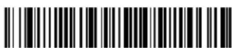
DLYRRD750
* Medium (750 ms)
DLYRRD1000.
Long (1000 ms)
DLYRRD2000.
Extra Long (2000 ms)
User-Specified Reread Delay
If you want to set your own length for the reread delay, scan the bar code below, then set the delay (from 0-30,000 milliseconds) by scanning digits from the inside back cover, then scanning Save.

DLYRRD
User-Specified Reread Delay
CodeGate®
When CodeGate is On, the trigger is used to allow decoded data to be transmitted to the host system. The scanner remains on, scanning and decoding bar codes, but the bar code data is not transmitted until the trigger is pressed. When CodeGate is Off, bar code data is transmitted when it is decoded. Default = CodeGate On Out-of-Stand.
AOSCGDO.
CodeGate Off
Out-of-Stand
AOSCGD1.
* CodeGate On
Out-of-Stand
Character Activation Mode
You may use a character sent from the host to trigger the scanner to begin scanning. When the activation character is received, the scanner continues scanning until either the Character Activation Timeout (page 3-12), the deactivation character is received (see Deactivation Character on page 3-13), or a bar code is transmitted. Scan the following On bar code to use character activation, then use Activation Character (following) to select the character you will send from the host to start scanning. Default = Off.

HSTCENO.
* Off

HSTCEN1
On
Activation Character
This sets the character used to trigger scanning when using Character Activation Mode. On the ASCII Conversion Chart (Code Page 1252), page A-2, find the hex value that represents the character you want to use to trigger scanning. Scan the following bar code, then use the Programming Chart to read the alphanumeric combination that represents that ASCII character. Scan Save to finish. Default = 18 [CAN].

HSTACH.
Activation Character
End Character Activation After Good Read
After a bar code is successfully detected and read from the scanner, the illumination can be programmed either to remain on and scanning, or to turn off. When End Character Activation After Good Read is enabled, the illumination turns off and stops scanning after a good read. If you scan Do Not End Character Activation After Good Read, the illumination remains on after a good read. Default = End Character Activation After Good Read.
Do Not End Character Activation After Good Read

* End Character Activation After Good Read
Character Activation Timeout
You can set a timeout for the length of time the illumination remains on and attempting to decode bar codes when using Character Activation Mode. Set the length (in milliseconds) for a timeout by scanning the following bar code, then setting the timeout (from 1-65,535 milliseconds) by scanning digits from the Programming Chart inside the back cover of this manual, then scanning Save. Default = 5000 ms.

Character Activation Timeout
Character Deactivation Mode
If you have sent a character from the host to trigger the scanner to begin scanning, you can also send a deactivation character to stop scanning. Scan the following On bar code to use character deactivation, then use Deactivation Character (following) to select the character you will send from the host to terminate scanning. Default = Off.


Deactivation Character
This sets the character used to terminate scanning when using Character Deactivation Mode. On the ASCII Conversion Chart (Code Page 1252), page A-2, find the hex value that represents the character you want to use to terminate scanning. Scan the following bar code, then use the Programming Chart inside the back cover of this manual to read the alphanumeric combination that represents that ASCII character. Scan Save to finish. Default = 68 [h].
HSTDCH.
Deactivation Character
Centering
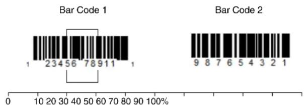
Use Centering to narrow the scanner's field of view to make sure that when the scanner is hand-held, it reads only those bar codes intended by the user. For instance, if multiple codes are placed closely together, centering will insure that only the desired codes are read. (Centering can be used in conjunction with Centering, page 3-13, for the most error-free operation in applications where multiple codes are spaced closely together. Using the Aimer Delay and Centering features, the scanner can emulate the operation of older systems, such as linear laser bar code scanners.)
If a bar code is not touched by a predefined window, it will not be decoded or output by the scanner. If centering is turned on by scanning Centering On, the scanner only reads codes that pass through the centering window you specify using the Left and Right of Centering Window bar codes.
In the example below, the white box is the centering window. The centering window has been set to 20% left and 30% right. Since Bar Code 1 passes through the centering window, it will be read. Bar Code 2 does not pass through the centering window, so it will not be read.
bar
| Bar Code | Value | | -------- | ----- | | 1 | 1 | | 2 | 23 | | 3 | 45 | | 4 | 56 | | 5 | 78 | | 6 | 91 | | 7 | 11 | | 8 | 1 | | 9 | 8 | | 10 | 7 | | 11 | 6 | | 12 | 5 | | 13 | 4 | | 14 | 3 | | 15 | 2 | | 16 | 1 |Note: A bar code needs only to be touched by the centering window in order to be read. It does not need to pass completely through the centering window.
Scan Centering On, then scan one of the following bar codes to change the left or right of the centering window. Then scan the percent you want to shift the centering window using digits on the inside back cover of this manual. Scan Save. Default Centering = 40% Left, 60% Right.

DECWIN1
Centering On

DECWIND
* Centering Off

DECLFT
Left of Centering Window
Blinky Mode
When either Blinky Mode On or Blinky Always On/Continuous is scanned, the scanner blinks on and off at 50% duty cycle (250 milliseconds on, then 250 milliseconds off.) Default = Blinky Mode Off.

BLKMOD0
* Blinky Mode Off

BLKMOD1
Blinky Mode On

BLKMOD2
Blinky Always On/
Continuous
Laser Scan Angle
The laser scan angle can be set to several different widths in order to adjust to your particular scanning requirements.
Full Laser Beam Sweep: This is the default setting that produces a 13.5° laser beam.
Reduced Laser Beam Sweep: If you are aiming at a longer distance and the laser beam becomes too wide and touches adjacent bar codes, you may need to adjust the width of the beam. In this case, scan the Reduced Laser Beam Sweep bar code below to narrow the laser beam.
Wide Laser Beam Sweep: If you have an exceptionally wide medium or high density bar code, you could use the wider sweep so the laser beam encompasses all of the code.
Note: When using Wide Laser Beam Sweep, the depth of field is reduced.

LASANGO
* Full Laser Beam Sweep

LASANG1
Reduced Laser Beam Sweep

LASANG2
Wide Laser Beam Sweep
Decode Security
This selection allows you to adjust the decode security needed while scanning. For good quality codes, choose Low to achieve fast scan speed. For codes prone to misreads, choose High. Default = Low.
Note: Increasing the security level may decrease the scan speed.

PAPLS1
* Low

PAPLS2
Low/Medium
PAPLS3
Medium/High

PAPLS4
High
Continuous Scan Mode
This programs the engine to continuously scan and decode, with the laser and motor staying on.
Note: When operating in Continuous Scan Mode, the scanner's upper operating temperature is 104ircF (40ircC) .

PAPPM3.
Continuous Scan Mode
Output Sequence Overview
Output Sequence Editor
This programming selection allows you to program the scanner to output data (when scanning more than one symbol) in whatever order your application requires, regardless of the order in which the bar codes are scanned. Reading the Default Sequence symbol programs the scanner to the Universal values, shown below. These are the defaults. Be certain you want to delete or clear all formats before you read the Default Sequence symbol.
Note: To make Output Sequence Editor selections, you'll need to know the code I.D., code length, and character match(es) your application requires. Use the Alphanumeric symbols (inside back cover) to read these options. You must hold the trigger while reading each bar code in the sequence.
To Add an Output Sequence
- Scan the Enter Sequence symbol (see Require Output Sequence, page 3-19).
- Code I.D.
On the Symbology Charts on page A-1, find the symbology to which you want to apply the output sequence format. Locate the Hex value for that symbology and scan the 2 digit hex value from the Programming Chart (inside back cover).
- Length
Specify what length (up to 9999 characters) of data output will be acceptable for this symbology. Scan the four digit data length from the Programming Chart. (Note: 50 characters is entered as 0050. 9999 is a universal number,
indicating all lengths.) When calculating the length, you must count any programmed prefixes, suffixes, or formatted characters as part of the length (unless using 9999).
4. Character Match Sequences
On the ASCII Conversion Chart (Code Page 1252), page A-2, find the Hex value that represents the character(s) you want to match. Use the Programming Chart to read the alphanumeric combination that represents the ASCII characters. (99 is the Universal number, indicating all characters.)
5. End Output Sequence Editor
Scan F F to enter an Output Sequence for an additional symbology, or Save to save your entries.
Other Programming Selections
- Discard
This exits without saving any Output Sequence changes.
Output Sequence Example
In this example, you are scanning Code 93, Code 128, and Code 39 bar codes, but you want the scanner to output Code 39 1st, Code 128 2nd, and Code 93 3rd, as shown below.
Note: Code 93 must be enabled to use this example.

A - Code 39

B - Code 128

C - Code 93
You would set up the sequence editor with the following command line:
SEQBLK62999941FF6A999942FF69999943FF
The breakdown of the command line is shown below:
SEQBLKsequence editor start command
62 code identifier for Code 39
9999 code length that must match for Code 39, 9999 = all lengths
41 start character match for Code 39, 41h = "A"
FF termination string for first code
6A code identifier for Code 128
9999 code length that must match for Code 128, 9999 = all lengths
42 start character match for Code 128, 42h = "B"
FF termination string for second code
69 code identifier for Code 93
9999 code length that must match for Code 93, 9999 = all lengths
43 start character match for Code 93, 43h = "C"
FF termination string for third code
To program the previous example using specific lengths, you would have to count any programmed prefixes, suffixes, or formatted characters as part of the length. If you use the example on page 3-17, but assume a
SEQBLK62001241FF6A001342FF69001243FF
The breakdown of the command line is shown below:
SEQBLKsequence editor start command
62 code identifier for Code 39
0012 A - Code 39 sample length (11) plus CR suffix (1) = 12
41 start character match for Code 39, 41h = "A"
FF termination string for first code
6A code identifier for Code 128
0013 B - Code 128 sample length (12) plus CR suffix (1) = 13
42 start character match for Code 128, 42h = "B"
FF termination string for second code
69 code identifier for Code 93
0012 C - Code 93 sample length (11) plus CR suffix (1) = 12
43 start character match for Code 93, 43h = "C"
FF termination string for third code
Output Sequence Editor

SEQBLK.
Enter Sequence

SEQDFT.
Default Sequence
Sequence Timeout
You may wish to set the maximum time between bar code scans in an output sequence. If that maximum time is not met, the output sequence operation is terminated. Set the length (in milliseconds) for a timeout by scanning the following bar code, then setting the timeout (from 1-65535 milliseconds) by scanning digits from the Programming Chart, then scanning Save. Default = 5000 msec.

SEQDLY.
Sequence Timeout
Sequence Match Beeper
By default, the scanner beeps when a sequence match is found. If you want the scanner to remain silent, scan the following Sequence Match Beeper Off bar code. Default = Sequence Match Beeper On.

SEQBEPO
Sequence Match Beeper Off
SEQBEP1.
* Sequence Match Beeper On
Partial Sequence
If an output sequence operation is terminated before all your output sequence criteria are met, the bar code data acquired to that point is a “partial sequence.”
Scan Discard Partial Sequence to discard partial sequences when the output sequence operation is terminated before completion. Scan Transmit Partial Sequence to transmit partial sequences. (Any fields in the sequence where no data match occurred will be skipped in the output.)

SEQTTS1
Transmit Partial Sequence

SEQTTSD
* Discard Partial Sequence
Require Output Sequence
When an output sequence is Required, all output data must conform to an edited sequence or the scanner will not transmit the output data to the host device. When it's On/Not Required, the scanner will attempt to get the output data to conform to an edited sequence but, if it cannot, the scanner transmits all output data to the host device as is.
When the output sequence is Off, the bar code data is output to the host as the scanner decodes it. Default = Off.
Note: This selection is unavailable when the Multiple Symbols Selection is turned on.

SEQ EN2.
Required

SEQ EN1
On/Not Required
SEQ END.
*Off
No Read
With No Read turned On, the scanner notifies you if a code cannot be read. If using an EZConfig-Scanning Tool Scan Data Window (see page 7-2), an "NR" appears when a code cannot be read. If No Read is turned Off, the "NR" will not appear. Default = Off.

SHWNRD1.
On

SHWNRDO.
* Off
If you want a different notation than "NR," for example, "Error," or "Bad Code," you can edit the output message (see Data Formatting beginning on page 5-1). The hex code for the No Read symbol is 9C.
Prefix/Suffix Overview
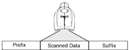
When a bar code is scanned, additional information is sent to the host computer along with the bar code data. This group of bar code data and additional, user-defined data is called a "message string." The selections in this section are used to build the user-defined data into the message string.
Prefix and Suffix characters are data characters that can be sent before and after scanned data. You can specify if they should be sent with all symbologies, or only with specific symbologies. The following illustration shows the breakdown of a message string:
flowchart
graph TD
    A["Prefix"] --> B["Scanned Data"]
    B --> C["Suffix"]
alpha numeric & control characters
variable length1-11
1-11 alpha numeric & control characters
Points to Keep In Mind
- It is not necessary to build a message string. The selections in this chapter are only used if you wish to alter the default settings. Default prefix = None. Default suffix = None.
- A prefix or suffix may be added or cleared from one symbology or all symbologies.
- You can add any prefix or suffix from the ASCII Conversion Chart (Code Page 1252), beginning on page A-2, plus Code I.D. and AIM I.D.
- You can string together several entries for several symbologies at one time.
- Enter prefixes and suffixes in the order in which you want them to appear on the output.
- When setting up for specific symbologies (as opposed to all symbologies), the specific symbology ID value counts as an added prefix or suffix character.
- The maximum size of a prefix or suffix configuration is 200 characters, which includes header information.
To Add a Prefix or Suffix:
Step 1. Scan the Add Prefix or Add Suffix symbol (page 4-2).
Step 2. Determine the 2 digit Hex value from the Symbology Chart (included in the Symbology Charts, beginning on page A-1) for the symbology to which you want to apply the prefix or suffix. For example, for Code 128, Code ID is "j" and Hex ID is "6A".
Step 3. Scan the 2 hex digits from the Programming Chart inside the back cover of this manual or scan 9, 9 for all symbologies.
Step 4. Determine the hex value from the ASCII Conversion Chart (Code Page 1252), beginning on page A-2, for the prefix or suffix you wish to enter.
Step 5. Scan the 2 digit hex value from the Programming Chart inside the back cover of this manual.
Step 6. Repeat Steps 4 and 5 for every prefix or suffix character.
Step 7. To add the Code I.D., scan 5, C, 8, 0. To add AIM I.D., scan 5, C, 8, 1. To add a backslash ( ), scan 5, C, 5, C.
Note: To add a backslash ( ) as in Step 7, you must scan 5C twice – once to create the leading backslash and then to create the backslash itself.
Step 8. Scan Save to exit and save, or scan Discard to exit without saving.
Repeat Steps 1-6 to add a prefix or suffix for another symbology.
Example: Add a Tab Suffix to All Symbologies
Step 1. Scan Add Suffix.
Step 2. Scan 9, 9 from the Programming Chart inside the back cover of this manual to apply this suffix to all symbologies.
Step 3. Scan 0, 9 from the Programming Chart inside the back cover of this manual. This corresponds with the hex value for a horizontal tab, shown in the ASCII Conversion Chart (Code Page 1252), beginning on page A-2.
Step 4. Scan Save, or scan Discard to exit without saving.
To Clear One or All Prefixes or Suffixes
You can clear a single prefix or suffix, or clear all prefixes/suffixes for a symbology. If you have been entering prefixes and suffixes for single symbologies, you can use Clear One Prefix (Suffix) to delete a specific character from a symbology. When you Clear All Prefixes (Suffixes), all the prefixes or suffixes for a symbology are deleted.
Step 1. Scan the Clear One Prefix or Clear One Suffix symbol.
Step 2. Determine the 2 digit Hex value from the Symbology Chart (included in the Symbology Charts, beginning on page A-1) for the symbology from which you want to clear the prefix or suffix.
Step 3. Scan the 2 digit hex value from the Programming Chart inside the back cover of this manual or scan 9, 9 for all symbologies.
Your change is automatically saved.
To Add a Carriage Return Suffix to All Symbologies
Scan the following bar code if you wish to add a carriage return suffix to all symbologies at once. This action first clears all current suffixes, then programs a carriage return suffix for all symbologies.

VSUFCR.
Add CR Suffix All Symbologies
Prefix Selections

PREBK2.
Add Prefix

PRECL2
Clear One Prefix
PRECA2.
Clear All Prefixes
Suffix Selections

SUFBK2
Add Suffix

SUFCA2
Clear All Suffixes

SUFCL2.
Clear One Suffix
Function Code Transmit
When this selection is enabled and function codes are contained within the scanned data, the scanner transmits the function code to the terminal. Charts of these function codes are provided in Supported Interface Keys starting on page 7-2. When the scanner is in keyboard wedge mode, the scan code is converted to a key code before it is transmitted. Default = Enable.
RMVFNCO
* Enable
RMVFNC1
Disable
Communication Check Character
To enhance security, you can specify the transmission type of a check character; either LRC where the calculation starts on the first transmitted character, or LRC where the calculation starts on the second transmitted character.
Note: This option adds a check character to the bar code data for all symbologies. If you need to enable or disable check characters for individual symbologies, see Symbologies beginning on page 6-1.
Scan the following bar code to set the communication check character type. Default = None.

HSTXRCO
* None

HSTXRC1
LRC Starts on 1st Character

HSTXRC2
LRC Starts on 2nd Character
Intercharacter, Interfunction, and Intermessage Delays
Some terminals drop information (characters) if data comes through too quickly. Intercharacter, interfunction, and intermessage delays slow the transmission of data, increasing data integrity.
Intercharacter Delay
An intercharacter delay of up to 5000 milliseconds (in 5ms increments) may be placed between the transmission of each character of scanned data. Scan the Intercharacter Delay bar code below, then scan the number of 5ms delays, and the Save bar code using the Programming Chart inside the back cover of this manual.

To remove this delay, scan the Intercharacter Delay bar code, then set the number of delays to 0. Scan the Save bar code using the Programming Chart inside the back cover of this manual.
User Specified Intercharacter Delay
An intercharacter delay of up to 5000 milliseconds (in 5ms increments) may be placed after the transmission of a particular character of scanned data. Scan the Delay Length bar code below, then scan the number of 5ms delays, and the Save bar code using the Programming Chart inside the back cover of this manual.
Next, scan the Character to Trigger Delay bar code, then the 2-digit hex value for the ASCII character that will trigger the delay ASCII Conversion Chart (Code Page 1252), beginning on page A-2.


To remove this delay, scan the Delay Length bar code, and set the number of delays to 0. Scan the Save bar code using the Programming Chart inside the back cover of this manual.
Interfunction Delay
An interfunction delay of up to 5000 milliseconds (in 5ms increments) may be placed between the transmission of each control character in the message string. Scan the Interfunction Delay bar code below, then scan the number of 5ms delays, and the Save bar code using the Programming Chart inside the back cover of this manual.

flowchart
graph TD
    A["Prefix Scanned Data Suffix"] --> B["STX"]
    A --> C["1"]
    A --> D["HT"]
    A --> E["2"]
    A --> F["3"]
    A --> G["4"]
    A --> H["5"]
    A --> I["CR"]
    A --> J["LF"]
    K["Interfunction Delays"] --> B
    K --> C
    K --> D
    K --> E
    K --> F
    K --> G
    K --> H
    K --> I
    K --> J
    L["DLYFNC. Interfunction Delay"] --> K
To remove this delay, scan the Interfunction Delay bar code, then set the number of delays to 0. Scan the Save bar code using the Programming Chart inside the back cover of this manual.
Intermessage Delay
An intermessage delay of up to 5000 milliseconds (in 5ms increments) may be placed between each scan transmission. Scan the Intermessage Delay bar code below, then scan the number of 5ms delays, and the Save bar code using the Programming Chart inside the back cover of this manual.

To remove this delay, scan the Intermessage Delay bar code, then set the number of delays to 0. Scan the Save bar code using the Programming Chart inside the back cover of this manual.
Data Format Editor Introduction
You may use the Data Format Editor to change the scanner's output. For example, you can use the Data Format Editor to insert characters at certain points in bar code data as it is scanned. The selections in the following pages are used only if you wish to alter the output. Default Data Format setting = None.
Normally, when you scan a bar code, it is output automatically. However, when you create a format, you must use a "send" command (see Send Commands on page 5-3) within the format program to output data.
Multiple formats may be programmed into the scanner. They are stacked in the order in which they are entered. However, the following list presents the order in which formats are applied:
- Specific Terminal ID, Actual Code ID, Actual Length
- Specific Terminal ID, Actual Code ID, Universal Length
- Specific Terminal ID, Universal Code ID, Actual Length
- Specific Terminal ID, Universal Code ID, Universal Length
- Universal Terminal ID, Actual Code ID, Actual Length
- Universal Terminal ID, Actual Code ID, Universal Length
- Universal Terminal ID, Universal Code ID, Actual Length
- Universal Terminal ID, Universal Code ID, Universal Length
The maximum size of a data format configuration is 2000 bytes, which includes header information.
If a bar code is read that fails the first data format, the next data format, if there is one, will be used on the bar code data. If there is no other data format, the raw data is output.
If you have changed data format settings, and wish to clear all formats and return to the factory defaults, scan the Default Data Format code below.

DFMDF3
* Default Data Format
Add a Data Format
Step 1. Scan the Enter Data Format symbol (page 5-2).
Step 2. Select Primary/Alternate Format
Determine if this will be your primary data format, or one of 3 alternate formats. This allows you to save a total of 4 different data formats. To program your primary format, scan 0 using the Programming Chart inside the back cover of this manual. If you are programming an alternate format, scan 1, 2, or 3, depending on which alternate format you are programming. (See "Primary/Alternate Data Formats" on page 5-12 for further information.)
Step 3. Terminal Type
Refer to Terminal ID Table (page 5-3) and locate the Terminal ID number for your PC. Scan three numeric bar codes on the inside back cover to program the scanner for your terminal ID (you must enter 3 digits). For example, scan 0 0 3 for an AT wedge.
Note: 099 indicates all terminal types.
Step 4. Code I.D.
In the Symbology Charts, beginning on page A-1, find the symbology to which you want to apply the data format. Locate the Hex value for that symbology and scan the 2 digit hex value from the Programming Chart inside the back cover of this manual.
If you wish to create a data format for all symbologies, with the exception of some specific symbologies, refer to B8 (page 5-11).
Note: 99 indicates all symbologies.
Step 5. Length
Specify what length (up to 9999 characters) of data will be acceptable for this symbology. Scan the four digit data length from the Programming Chart inside the back cover of this manual. For example, 50 characters is entered as 0050. Note: 9999 indicates all lengths.
Step 6. Editor Commands
Refer to Data Format Editor Commands (page 5-3). Scan the symbols that represent the command you want to enter. 94 alphanumeric characters may be entered for each symbology data format.
Step 7. Scan Save to save your data format, or Discard to exit without saving your changes.

Other Programming Selections
Clear One Data Format
This deletes one data format for one symbology. If you are clearing the primary format, scan 0 from the Programming Chart inside the back cover of this manual. If you are clearing an alternate format, scan 1, 2, or 3, depending on the format you are clearing. Scan the Terminal Type and Code I.D. (see Symbology Charts on page A-1), and the bar code data length for the specific data format that you want to delete. All other formats remain unaffected.
Clear all Data Formats
This clears all data formats.
Save to exit and save your data format changes.
Discard to exit without saving any data format changes.


Terminal ID Table
| Terminal Model(s) Terminal ID | |
| Serial RS232 True | 000 |
Data Format Editor Commands
When working with the Data Format Editor, a virtual cursor is moved along your input data string. The following commands are used to both move this cursor to different positions, and to select, replace, and insert data into the final output.
Send Commands
Send all characters
F1 Include in the output message all of the characters from the input message, starting from current cursor position, followed by an insert character. Syntax = F1xx where xx stands for the insert character's hex value for its ASCII code. Refer to the ASCII Conversion Chart (Code Page 1252), beginning on page A-2 for decimal, hex and character codes.
Send a number of characters
F2 Include in the output message a number of characters followed by an insert character. Start from the current cursor position and continue for "nn" characters or through the last character in the input message, followed by character "xx." Syntax = F2nnxx where nn stands for the numeric value (00-99) for the number of characters, and xx stands for the insert character's hex value for its ASCII code. Refer to the ASCII Conversion Chart (Code Page 1252), beginning on page A-2 for decimal, hex and character codes.
F2 Example: Send a number of characters

Send the first 10 characters from the bar code above, followed by a carriage return. Command string: F2100D
F2 is the "Send a number of characters" command
10 is the number of characters to send
0D is the hex value for a CR
The data is output as: 1234567890
F2 and F1 Example: Split characters into 2 lines
Send the first 10 characters from the bar code above, followed by a carriage return, followed by the rest of the characters.
Command string: F2100DF10D
F2 is the "Send a number of characters" command
10 is the number of characters to send for the first line
0D is the hex value for a CR
F1 is the "Send all characters" command
0D is the hex value for a CR
The data is output as:
1234567890
ABCDEFGHIJ
Send all characters up to a particular character
F3 Include in the output message all characters from the input message, starting with the character at the current cursor position and continuing to, but not including, the search character "ss," followed by an insert character. The cursor is moved forward to the "ss" character. Syntax = F3ssxx where ss stands for the search character's hex value for its ASCII code, and xx stands for the insert character's hex value for its ASCII code. Refer to the ASCII Conversion Chart (Code Page 1252), beginning on page A-2 for decimal, hex and character codes.
F3 Example: Send all characters up to a particular character

Using the bar code above, send all characters up to but not including "D," followed by a carriage return.
Command string: F3440D
F3 is the "Send all characters up to a particular character" command
44 is the hex value for a 'D"
0D is the hex value for a CR
The data is output as:
1234567890ABC
Send all characters up to a string
B9 Include in the output message all characters from the input message, starting with the character at the current cursor position and continuing to, but not including, the search string "s...s." The cursor is moved forward to the beginning of the "s...s" string. Syntax = B9nnnns...s where nnnn stands for the length of the string, and s...s stands for the string to be matched. The string is made up of hex values for the characters in the string. Refer to the ASCII Conversion Chart (Code Page 1252), beginning on page A-2 for decimal, hex and character codes.
B9 Example: Send all characters up to a defined string

Using the bar code above, send all characters up to but not including "AB."
Command string: B900024142
B9 is the "Send all characters up to a string" command
0002 is the length of the string (2 characters)
41 is the hex value for A
42 is the hex value for B
The data is output as: 1234567890
Send all but the last characters
E9 Include in the output message all but the last "nn" characters, starting from the current cursor position. The cursor is moved forward to one position past the last input message character included. Syntax = E9nn where nn stands for the numeric value (00-99) for the number of characters that will not be sent at the end of the message.
Insert a character multiple times
F4 Send "xx" character "nn" times in the output message, leaving the cursor in the current position. Syntax = F4xxnn where xx stands for the insert character's hex value for its ASCII code, and nn is the numeric value (00-99) for the number of times it should be sent. Refer to the ASCII Conversion Chart (Code Page 1252), beginning on page A-2 for decimal, hex and character codes.
E9 and F4 Example: Send all but the last characters, followed by 2 tabs

Send all characters except for the last 8 from the bar code above, followed by 2 tabs.
Command string: E908F40902
E9 is the "Send all but the last characters" command
08 is the number of characters at the end to ignore
F4 is the "Insert a character multiple times" command
09 is the hex value for a horizontal tab
02 is the number of times the tab character is sent
The data is output as: 1234567890AB
Insert a string
BA Send "ss" string of "nn" length in the output message, leaving the cursor in the current position. Syntax = BAnnnns...s where nnnn stands for the length of the string, and s...s stands for the string. The string is made up of hex values for the characters in the string. Refer to the ASCII Conversion Chart (Code Page 1252), beginning on page A-2 for decimal, hex and character codes.
B9 and BA Example: Look for the string "AB" and insert 2 asterisks (**)

Using the bar code above, send all characters up to but not including "AB." Insert 2 asterisks at that point, and send the rest of the data with a carriage return after.
Command string: B900024142BA00022A2AF10D
B9 is the "Send all characters up to a string" command
0002 is the length of the string (2 characters)
41 is the hex value for A
42 is the hex value for B
BA is the "Insert a string" command
0002 is the length of the string to be added (2 characters)
2A is the hex value for an asterisk (*)
2A is the hex value for an asterisk (*)
F1 is the "Send all characters" command
0D is the hex value for a CR
The data is output as:
1234567890**ABCDEFGHIJ
Insert symbology name
B3 Insert the name of the bar code's symbology in the output message, without moving the cursor. Only symbologies with a Honeywell ID are included (see Symbology Charts on page A-1). Refer to the ASCII Conversion Chart (Code Page 1252), beginning on page A-2 for decimal, hex and character codes.
Insert bar code length
B4 Insert the bar code's length in the output message, without moving the cursor. The length is expressed as a numeric string and does not include leading zeroes.
B3 and B4 Example: Insert the symbology name and length

Send the symbology name and length before the bar code data from the bar code above. Break up these insertions with spaces. End with a carriage return.
Command string: B3F42001B4F42001F10D
B3 is the "Insert symbology name" command
F4 is the "Insert a character multiple times" command
20 is the hex value for a space
01 is the number of times the space character is sent
B4 is the "Insert bar code length" command
F4 is the "Insert a character multiple times" command
20 is the hex value for a space
01 is the number of times the space character is sent
F1 is the "Send all characters" command
0D is the hex value for a CR
The data is output as:
Code128 20 1234567890ABCDEFGHIJ
Insert key strokes
B5 Insert a key stroke or combination of key strokes. Key strokes are dependent on your keyboard (see Unicode Key Maps on page A-9). Any key can be inserted, including arrows and functions. Syntax = B5xxssnn where xx is the number of keys pressed (without key modifiers), ss is the key modifier from the table below, and nn is the key number from the Unicode Key Maps, page A-9.
| Key Modifiers | |
| No Key Modifier 00 | |
| Shift Left 01 | |
| Shift Right 02 | |
| Alt Left 04 | |
| Alt Right 08 | |
| Control Left 10 | |
| Control Right 20 | |
For example, B501021F inserts an "A" on a 104 key, U.S. style keyboard. B5 = the command, 01 = number of keys pressed (without the key modifier), 02 is the key modifier for Shift Right, and 1F is the "a" key. If a lower case "a" were to be inserted, B501001F would be entered.
If there are three keystrokes, the syntax would change from B5xxssnn for one keystroke to B5xxssnnssnnssnn. An example that would insert "abc" is as follows: B503001F00320030F833.
Note: Key modifiers can be added together when needed. Example: Control Left+Shift Left = 11.
Move Commands
Move the cursor forward a number of characters
F5 Move the cursor ahead "nn" characters from current cursor position.
Syntax = F5nn where nn is the numeric value (00-99) for the number of characters the cursor should be moved ahead.
F5 Example: Move the cursor forward and send the data

Move the cursor forward 3 characters, then send the rest of the bar code data from the bar code above. End with a carriage return.
Command string: F503F10D
F5 is the "Move the cursor forward a number of characters" command
03 is the number of characters to move the cursor
F1 is the "Send all characters" command
0D is the hex value for a CR
The data is output as:
4567890ABCDEFGHIJ
Move the cursor backward a number of characters
F6 Move the cursor back "nn" characters from current cursor position.
Syntax = F6nn where nn is the numeric value (00-99) for the number of characters the cursor should be moved back.
Move the cursor to the beginning
F7 Move the cursor to the first character in the input message. Syntax = F7.
FE and F7 Example: Manipulate bar codes that begin with a 1

Search for bar codes that begin with a 1. If a bar code matches, move the cursor back to the beginning of the data and send 6 characters followed by a carriage return. Using the bar code above:
Command string: FE31F7F2060D
FE is the "Compare characters" command
31 is the hex value for 1
F7 is the "Move the cursor to the beginning" command
F2 is the "Send a number of characters" command
06 is the number of characters to send
0D is the hex value for a CR
The data is output as:
123456
Move the cursor to the end
EA Move the cursor to the last character in the input message. Syntax = EA.
Search Commands
Search forward for a character
F8 Search the input message forward for "xx" character from the current cursor position, leaving the cursor pointing to the "xx" character. Syntax = F8xx where xx stands for the search character's hex value for its ASCII code. Refer to the ASCII Conversion Chart (Code Page 1252), beginning on page A-2 for decimal, hex and character codes.
F8 Example: Send bar code data that starts after a particular character

Search for the letter "D" in bar codes and send all the data that follows, including the "D." Using the bar code above:
Command string: F844F10D
F8 is the "Search forward for a character" command
44 is the hex value for "D"
F1 is the "Send all characters" command
0D is the hex value for a CR
The data is output as:
DEFGHIJ
Search backward for a character
F9 Search the input message backward for "xx" character from the current cursor position, leaving the cursor pointing to the "xx" character. Syntax = F9xx where xx stands for the search character's hex value for its ASCII code. Refer to the ASCII Conversion Chart (Code Page 1252), beginning on page A-2 for decimal, hex and character codes.
Search forward for a string
B0 Search forward for "s" string from the current cursor position, leaving cursor pointing to "s" string. Syntax = B0nnnnS where nnnn is the string length (up to 9999), and S consists of the ASCII hex value of each character in the match string. For example, B0000454657374 will search forward for the first occurrence of the 4 character string "Test." Refer to the ASCII Conversion Chart (Code Page 1252), beginning on page A-2 for decimal, hex and character codes.
B0 Example: Send bar code data that starts after a string of characters

1234567890ABCDEFGHIJ
Search for the letters "FGH" in bar codes and send all the data that follows, including "FGH." Using the bar code above:
Command string: B00003464748F10D
B0 is the "Search forward for a string" command
0003 is the string length (3 characters)
46 is the hex value for "F"
47 is the hex value for "G"
48 is the hex value for "H"
F1 is the "Send all characters" command
0D is the hex value for a CR
The data is output as:
FGHIJ
Search backward for a string
B1 Search backward for "s" string from the current cursor position, leaving cursor pointing to "s" string. Syntax = B1nnnnS where nnnn is the string length (up to 9999), and S consists of the ASCII hex value of each character in the match string. For example, B1000454657374 will search backward for the first occurrence of the 4 character string "Test." Refer to the ASCII Conversion Chart (Code Page 1252), beginning on page A-2 for decimal, hex and character codes.
Search forward for a non-matching character
E6 Search the input message forward for the first non-“xx” character from the current cursor position, leaving the cursor pointing to the non-“xx” character. Syntax = E6xx where xx stands for the search character's hex value for its ASCII code. Refer to the ASCII Conversion Chart (Code Page 1252), beginning on page A-2 for decimal, hex and character codes.
E6 Example: Remove zeroes at the beginning of bar code data

300037692
This example shows a bar code that has been zero filled. You may want to ignore the zeroes and send all the data that follows. E6 searches forward for the first character that is not zero, then sends all the data after, followed by a carriage return. Using the bar code above:
Command string: E630F10D
E6 is the "Search forward for a non-matching character" command
30 is the hex value for 0
F1 is the "Send all characters" command
0D is the hex value for a CR
The data is output as:
37692
Search backward for a non-matching character
E7 Search the input message backward for the first non-“xx” character from the current cursor position, leaving the cursor pointing to the non-“xx” character. Syntax = E7xx where xx stands for the search character's hex value for its ASCII code. Refer to the ASCII Conversion Chart (Code Page 1252), beginning on page A-2 for decimal, hex and character codes.
Miscellaneous Commands
Suppress characters
FB Suppress all occurrences of up to 15 different characters, starting at the current cursor position, as the cursor is advanced by other commands. When the FC command is encountered, the suppress function is terminated. The cursor is not moved by the FB command. Syntax = FBnnxxyy .. zz where nn is a count of the number of suppressed characters in the list, and xxyy .. zz is the list of characters to be suppressed.
FB Example: Remove spaces in bar code data
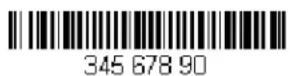
This example shows a bar code that has spaces in the data. You may want to remove the spaces before sending the data. Using the bar code above:
Command string: FB0120F10D
FB is the "Suppress characters" command
01 is the number of character types to be suppressed
20 is the hex value for a space
F1 is the "Send all characters" command
0D is the hex value for a CR
The data is output as:
34567890
Stop suppressing characters
FC Disables suppress filter and clear all suppressed characters. Syntax = FC.
Replace characters
E4 Replaces up to 15 characters in the output message, without moving the cursor. Replacement continues until the E5 command is encountered. Syntax = E4nnxx 1 xx 2 yy 1 yy 2 ...zz 1 zz 2 where nn is the total count of the number of characters in the list (characters to be replaced plus replacement characters); xx 1 defines characters to be replaced and xx 2 defines replacement characters, continuing through zz 1 and zz 2 .
E4 Example: Replace zeroes with CRs in bar code data

If the bar code has characters that the host application does not want included, you can use the E4 command to replace those characters with something else. In this example, you will replace the zeroes in the bar code above with carriage returns.
Command string: E402300DF10D
E4 is the "Replace characters" command
02 is the total count of characters to be replaced, plus the replacement characters (0 is replaced by CR, so total characters = 2)
30 is the hex value for 0
0D is the hex value for a CR (the character that will replace the 0)
F1 is the "Send all characters" command
0D is the hex value for a CR
The data is output as:
1234
5678
ABC
Stop replacing characters
E5 Terminates character replacement. Syntax = E5.
Compare characters
FE Compare the character in the current cursor position to the character "xx." If characters are equal, move the cursor forward one position. Syntax = FExx where xx stands for the comparison character's hex value for its ASCII code. Refer to the ASCII Conversion Chart (Code Page 1252), beginning on page A-2 for decimal, hex and character codes.
Compare string
B2 Compare the string in the input message to the string "s." If the strings are equal, move the cursor forward past the end of the string. Syntax = B2nnnnS where nnnn is the string length (up to 9999), and S consists of the ASCII hex value of each character in the match string. For example, B2000454657374 will compare the string at the current cursor position with the 4 character string "Test." Refer to the ASCII Conversion Chart (Code Page 1252), beginning on page A-2 for decimal, hex and character codes.
Check for a number
EC Check to make sure there is an ASCII number at the current cursor position. The format is aborted if the character is not numeric.
EC Example: Only output the data if the bar code begins with a number
If you want only data from bar codes that begin with a number, you can use EC to check for the number.
Command string: ECF10D
EC is the "Check for a number" command
F1 is the "Send all characters" command
0D is the hex value for a CR
If this bar code is read, AB1234 the next data format, if there is one, will be used on the data. If there
is no other format, the format fails and the raw data is output as AB1234.
If this bar code is read: the data outputs as: 1234AB
1234AB
Check for non-numeric character
ED Check to make sure there is a non-numeric ASCII character at the current cursor position. The format is aborted if the character is numeric.
ED Example: Only output the data if the bar code begins with a letter
If you want only data from bar codes that begin with a letter, you can use ED to check for the letter.
Command string: EDF10D
ED is the "Check for a non-numeric character" command
F1 is the "Send all characters" command
0D is the hex value for a CR

the next data format, if there is one, will be used on this data. If there
is no other format, the format fails and the raw data is output as 1234AB.

AB1234
Insert a delay
EF Inserts a delay of up to 49,995 milliseconds (in multiples of 5), starting from the current cursor position. Syntax = EFnnnn where nnnn stands for the delay in 5ms increments, up to 9999. This command can only be used with keyboard emulation.a
Discard Data
B8 Discards types of data. For example, you may want to discard Code 128 bar codes that begin with the letter A. In step 4 (page 5-1), select 6A (for Code 128), and in step 5, select 9999 (for all lengths). Enter FE41B8 to compare and discard Code 128 bar codes that begin with the letter A. Syntax = B8.
Note: The B8 command must be entered after all other commands.
The Data Format must be Required (see page 5-11) in order for the B8 command to work.
If Data Format is On, but Not Required (page 5-12), bar code data that meets the B8 format is scanned and output as usual.
Because the data format needs to be On and Required (page 5-12) for the B8 command, you must input data formats for all bar codes you wish to discard as well as all bar codes you wish to output.
Other data format settings impact the B8 command. If Data Format Non-Match Error Tone is On (page 5-12), the scanner emits an error tone. If Data format Non-Match Error Tone is Off, the code is disabled for reading and no tone is sounded.
Data Formatter
When Data Formatter is turned Off, the bar code data is output to the host as read, including prefixes and suffixes.

DFM ENO.
Data Formatter Off
You may wish to require the data to conform to a data format you have created and saved. The following settings can be applied to your data format:
Data Formatter On, Not Required, Keep Prefix/Suffix
Scanned data is modified according to your data format, and prefixes and suffixes are transmitted.
Data Formatter On, Not Required, Drop Prefix/Suffix
Scanned data is modified according to your data format. If a data format is found for a particular symbol, those prefixes and suffixes are not transmitted. If a data format is not found for that symbol, the prefixes and suffixes are transmitted.
Data Format Required, Keep Prefix/Suffix
Scanned data is modified according to your data format, and prefixes and suffixes are transmitted. Any data that does not match your data format requirements generates an error tone and the data in that bar code is not transmitted. If you wish to process this type of bar code without generating an error tone, see Data Format Non-Match Error Tone.
Data Format Required, Drop Prefix/Suffix
Scanned data is modified according to your data format. If a data format is found for a particular symbol, those prefixes and suffixes are not transmitted. Any data that does not match your data format requirements generates an error tone. If you wish to process this type of bar code without generating an error tone, see Data Format Non-Match Error Tone.
Choose one of the following options. Default = Data Formatter On, Not Required, Keep Prefix/Suffix.

DFM_EN1. * Data Formatter On, Not Required, Keep Prefix/Suffix

DFM_EN3. Data Formatter On, Not Required, Drop Prefix/Suffix

DFM_EN2. Data Format Required, Keep Prefix/Suffix
DFM_EN4. Data Format Required, Drop Prefix/Suffix
Data Format Non-Match Error Tone
When a bar code is encountered that doesn't match your required data format, the scanner normally generates an error tone. However, you may want to continue scanning bar codes without hearing the error tone. If you scan the Data Format Non-Match Error Tone Off bar code, data that doesn't conform to your data format is not transmitted, and no error tone will sound. If you wish to hear the error tone when a non-matching bar code is found, scan the Data Format Non-Match Error Tone On bar code. Default = Data Format Non-Match Error Tone On.

DFMDECO. * Data Format Non-Match Error Tone On

DFMDEC1. Data Format Non-Match Error Tone Off
Primary/Alternate Data Formats
You can save up to four data formats, and switch between these formats. Your primary data format is saved under 0. Your other three formats are saved under 1, 2, and 3. To set your device to use one of these formats, scan one of the bar codes below.
ALTFNMO. Primary Data Format

ALTFNM2
Data Format 2

ALTFNM1
Data Format 1

ALTFNM3
Data Format 3
Single Scan Data Format Change
You can also switch between data formats for a single scan. The next bar code is scanned using an alternate data format, then reverts to the format you have selected above (either Primary, 1, 2, or 3).
For example, you may have set your device to the data format you saved as Data Format 3. You can switch to Data Format 1 for a single trigger pull by scanning the Single Scan-Data Format 1 bar code below. The next bar code that is scanned uses Data Format 1, then reverts back to Data Format 3.

VSAF_0.
Single Scan-Primary Data Format

VSAF 1
Single Scan-Data Format 1

VSAF 2
Single Scan-Data Format 2

VSAF 3.
Single Scan-Data Format 3
This programming section contains the following menu selections. Refer to Chapter 8 for settings and defaults.
- All Symbologies • GS1 Emulation
• China Post (Hong Kong 2 of 5) • GS1-128
• Codabar • Interleaved 2 of 5
• Code 11 • Matrix 2 of 5 - Code 128 • MSI
• Code 32 Pharmaceutical (PARAF) • NEC 2 of 5
• Code 39 • Plessey Code
• Code 93 • Straight 2 of 5 IATA (two-bar start/stop)
• EAN/JAN-13 • Straight 2 of 5 Industrial (three-bar start/stop)
• EAN/JAN-8 • Telepen
• GS1 DataBar Expanded • Trioptic Code
• GS1 DataBar Limited • UPC-A
• GS1 DataBar Omnidirectional
- UPC-A/EAN-13 with Extended Coupon Code
- UPC-E0
All Symbologies
If you want to decode all the symbologies allowable for your scanner, scan the All Symbologies On code. If on the other hand, you want to decode only a particular symbology, scan All Symbologies Off followed by the On symbol for that particular symbology.

ALLENA1
All Symbologies On

ALLENAD
All Symbologies Off
Message Length Description
You are able to set the valid reading length of some of the bar code symbologies. If the data length of the scanned bar code doesn't match the valid reading length, the scanner will issue an error tone. You may wish to set the same value for minimum and maximum length to force the scanner to read fixed length bar code data. This helps reduce the chances of a misread.
EXAMPLE: Decode only those bar codes with a count of 9-20 characters.
Min. length = 09Max. length = 20
EXAMPLE: Decode only those bar codes with a count of 15 characters.
Min. length = 15Max. length = 15
For a value other than the minimum and maximum message length defaults, scan the bar codes included in the explanation of the symbology, then scan the digit value of the message length and Save bar codes on the Programming Chart inside the back cover of this manual. The minimum and maximum lengths and the defaults are included with the respective symbologies.
Codabar

Codabar On/Off


Codabar Start/Stop Characters
Start/Stop characters identify the leading and trailing ends of the bar code. You may either transmit, or not transmit Start/Stop characters. Default = Don't Transmit.


Codabar Check Character
Codabar check characters are created using different "modulos." You can program the scanner to read only Codabar bar codes with Modulo 16 check characters. Default = No Check Character.
No Check Character indicates that the scanner reads and transmits bar code data with or without a check character.
When Check Character is set to Validate and Transmit, the scanner will only read Codabar bar codes printed with a check character, and will transmit this character at the end of the scanned data.
When Check Character is set to Validate, but Don't Transmit, the unit will only read Codabar bar codes printed with a check character, but will not transmit the check character with the scanned data.
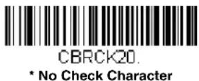


CBRCK22.
Validate Modulo 16 and Transmit

CBRCK23
Validate Modulo 7 CD, but Don't Transmit

CBRCK24
Validate Modulo 7 CD and Transmit

CBRCK25
Validate CLSI, but Don't Transmit

CBRCK26
Validate CLSI and Transmit
Codabar Concatenation
Codabar supports symbol concatenation. When you enable concatenation, the scanner looks for a Codabar symbol having a "D" start character, adjacent to a symbol having a "D" stop character. In this case the two messages are concatenated into one with the "D" characters omitted.

Select Require to prevent the scanner from decoding a single "D" Codabar symbol without its companion. This selection has no effect on Codabar symbols without Stop/Start D characters.

CBRCCT1
On

CBRCCTD
* Off
CBRCCT2
Require
Concatenation Timeout
When searching for bar codes during concatenation, you may wish to set a delay used to find the next bar code. Set the length (in milliseconds) for this delay by scanning the following bar code, then setting the timeout (from 1-65535 milliseconds) by scanning digits from the Programming Chart, then scanning Save. Default = 750.

DLYCCT.
Concatenation Timeout
Codabar Redundancy
If you are encountering errors when reading Codabar bar codes, you may want to adjust the redundancy count. Redundancy adjusts the number of times a bar code is decoded before transmission, which may reduce the number of errors. Note that the higher the redundancy count, the longer it will take to decode the bar code. To adjust the redundancy, scan the following Codabar Redundancy bar code, then scan a redundancy count between 0 and 10 on the Programming Chart inside the back cover of this manual. Then scan the Save bar code. Default = 0.

CBRVOT
Codabar Redundancy
Codabar Message Length
Scan the bar codes below to change the message length. Refer to Message Length Description (page 6-1) for additional information. Minimum and Maximum lengths = 1-80. Minimum Default = 3, Maximum Default = 80.

CBRMIN
Minimum Message Length

CBRMAX
Maximum Message Length
Code 39
< Default All Code 39 Settings >

Code 39 On/Off
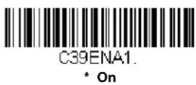
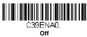
Code 39 Start/Stop Characters
Start/Stop characters identify the leading and trailing ends of the bar code. You may either transmit, or not transmit Start/Stop characters. Default = Don't Transmit.

Code 39 Check Character
No Check Character indicates that the scanner reads and transmits bar code data with or without a check character.
When Check Character is set to Validate, but Don't Transmit, the unit only reads Code 39 bar codes printed with a check character, but will not transmit the check character with the scanned data.
When Check Character is set to Validate and Transmit, the scanner only reads Code 39 bar codes printed with a check character, and will transmit this character at the end of the scanned data. Default = No Check Character.


Code 39 Redundancy
If you are encountering errors when reading Code 39 bar codes, you may want to adjust the redundancy count. Redundancy adjusts the number of times a bar code is decoded before transmission, which may reduce the number of errors. Note that the higher the redundancy count, the longer it will take to decode the bar code. To adjust the redundancy, scan the Code 39 Redundancy bar code below, then scan a redundancy count between 0 and 10 on the Programming Chart inside the back cover of this manual. Then scan the Save bar code. Default = 0.

C39VOT.
Code 39 Redundancy
Code 39 Message Length
Scan the bar codes below to change the message length. Refer to Message Length Description (page 6-1) for additional information. Minimum and Maximum lengths = 1-80. Minimum Default = 3, Maximum Default = 80.

C39MIN
Minimum Message Length

C39MAX
Maximum Message Length
Code 39 Append
This function allows the scanner to append the data from several Code 39 bar codes together before transmitting them to the host computer. When the scanner encounters a Code 39 bar code with the append trigger character(s), it buffers Code 39 bar codes until it reads a Code 39 bar code that does not have the append trigger. The data is then transmitted in the order in which the bar codes were read (FIFO). Default = Off.

C39APP1.
On

C39APP0.
* Off
Code 32 Pharmaceutical (PARAF)
Code 32 Pharmaceutical is a form of the Code 39 symbology used by Italian pharmacies. This symbology is also known as PARAF.
Note: Trioptic Code (page 6-50) must be turned off while scanning Code 32 Pharmaceutical codes.

C39B321
On
Full ASCII
If Full ASCII Code 39 decoding is enabled, certain character pairs within the bar code symbol will be interpreted as a single character. For example: \$V will be decoded as the ASCII character SYN, and /C will be decoded as the ASCII character #. Default = Off.
| NUL %U DLE P | SP SPACE | 0 | 0 | @ | % | V | P | P | ‘ | % | W | ||
| SOH SA | DC1Q | ! | /A | 1 | 1 | A | A | Q | Q | a | +A | q | +Q |
| STX B | DC2R | “ | /B | 2 | 2 | B | B | R | R | b | +B | r | +R |
| ETX C | DC3S | # | /C | 3 | 3 | C | C | S | S | c | +C | s | +S |
| EOT D | DC4T | /D | 4 | 4 | D | D | T | T | d | +D | t | +T | |
| ENQ SE | NAKU | % | /E | 5 | 5 | E | E | U | U | e | +E | u | +U |
| ACK F | SYNV | & | /F | 6 | 6 | F | F | V | V | f | +F | v | +V |
| BEL G | ETBW | ‘ | /G | 7 | 7 | G | G | W | W | g | +G | w | +W |
| BS H | CANX | ( | /H | 8 | 8 | H | H | X | X | h | +H | x | +X |
| HT I | EMY | ) | /I | 9 | 9 | I | I | Y | Y | i | +I | y | +Y |
| LF J | SUBZ | * | /J | : | /Z | J | J | Z | Z | j | +J | z | +Z |
| VT K | ESC %A | + | /K | ; | %F | K | K | [ | %K | k | +K | %P | |
| FFL | FS %B | , | /L | < | %G | L | L | \ | %L | l | +L | l | %Q |
| CR M | GS %C | - | - | = | %H | M | M | ] | %M | m | +M | %R | |
| SON | RS %D | . | . | > | %I | N | N | ^ | %N | n | +N | ~ | %S |
| SI $O | US %E | / | /O | ? | %J | O | O | _ | %O | o | +O | DEL | %T |
p + P
Character pairs /M and /N decode as a minus sign and period respectively.
Character pairs /P through /Y decode as 0 through 9.

C39ASC1
Full ASCII On

C39ASCO
* Full ASCII Off
Code 39 Code Page
Code pages define the mapping of character codes to characters. If the data received does not display with the proper characters, it may be because the bar code being scanned was created using a code page that is different from the one the host program is expecting. If this is the case, scan the bar code below, select the code page with which the bar codes were created (see ISO 2022/ISO 646 Character Replacements on page A-7), and scan the value and the Save bar code from the Programming Chart on the inside the back cover of this manual. The data characters should then appear properly.

C39DCP
Code 39 Code Page
Interleaved 2 of 5
< Default All Interleaved 2 of 5 Settings >

Interleaved 2 of 5 On/Off


NULL Characters
Interleaved 2 of 5 requires an even number of characters. When an odd number of characters is present, it is due to NULL characters embedded in the bar code. Scan the On bar code below to decode this type of Interleaved 2 of 5 bar code. Default = Off.


Check Digit
No Check Digit indicates that the scanner reads and transmits bar code data with or without a check digit.
When Check Digit is set to Validate, but Don't Transmit, the unit only reads Interleaved 2 of 5 bar codes printed with a check digit, but will not transmit the check digit with the scanned data.
When Check Digit is set to Validate and Transmit, the scanner only reads Interleaved 2 of 5 bar codes printed with a check digit, and will transmit this digit at the end of the scanned data. Default = No Check Digit.


125CK22
Validate and Transmit
Interleaved 2 of 5 Redundancy
If you are encountering errors when reading Interleaved 2 of 5 bar codes, you may want to adjust the redundancy count. Redundancy adjusts the number of times a bar code is decoded before transmission, which may reduce the number of errors. Note that the higher the redundancy count, the longer it will take to decode the bar code. To adjust the redundancy, scan the Interleaved 2 of 5 Redundancy bar code below, then scan a redundancy count between 0 and 10 on the Programming Chart inside the back cover of this manual. Then scan the Save bar code. Default = 0.

125VOT
Interleaved 2 of 5 Redundancy
Interleaved 2 of 5 Message Length
Scan the bar codes below to change the message length. Refer to Message Length Description (page 6-1) for additional information. Minimum and Maximum lengths = 2-80. Minimum Default = 4, Maximum Default = 80.

125MIN
Minimum Message Length

125MAX
Maximum Message Length
Matrix 2 of 5

x25DFT.
Matrix 2 of 5 On/Off

x25ENA1
On

x25ENAD
* Off
Matrix 2 of 5 Check Character
No Check Character indicates that the scanner reads and transmits bar code data with or without a check character.
When Check Character is set to Validate, but Don't Transmit, the unit only reads Matrix 2 of 5 bar codes printed with a check character, but will not transmit the check character with the scanned data.
When Check Character is set to Validate and Transmit, the scanner only reads Matrix 2 of 5 bar codes printed with a check character, and will transmit this character at the end of the scanned data. Default = No Check Character.

x25CK20
* No Check Character

x25CK21.
Validate, but Don't Transmit

x25CK22
Validate and Transmit
Matrix 2 of 5 Redundancy
If you are encountering errors when reading Matrix 2 of 5 bar codes, you may want to adjust the redundancy count. Redundancy adjusts the number of times a bar code is decoded before transmission, which may reduce the number of errors. Note that the higher the redundancy count, the longer it will take to decode the bar code. To adjust the redundancy, scan the Matrix 2 of 5 Redundancy bar code below, then scan a redundancy count between 0 and 10 on the Programming Chart inside the back cover of this manual. Then scan the Save bar code. Default = 0.

×25VOT
Matrix 2 of 5 Redundancy
Matrix 2 of 5 Message Length
Scan the bar codes below to change the message length. Refer to Message Length Description (page 6-1) for additional information. Minimum and Maximum lengths = 1-80. Minimum Default = 3, Maximum Default = 80.

X25MIN.
Minimum Message Length

X25MAX
Maximum Message Length
NEC 2 of 5
< Default All NEC 2 of 5 Settings >

NEC 2 of 5 On/Off


Check Digit
No Check Digit indicates that the scanner reads and transmits bar code data with or without a check digit.
When Check Digit is set to Validate, but Don't Transmit, the unit only reads NEC 2 of 5 bar codes printed with a check digit, but will not transmit the check digit with the scanned data.
When Check Digit is set to Validate and Transmit, the scanner only reads NEC 2 of 5 bar codes printed with a check digit, and will transmit this digit at the end of the scanned data. Default = No Check Digit.

NEC 2 of 5 Redundancy
If you are encountering errors when reading NEC 2 of 5 bar codes, you may want to adjust the redundancy count. Redundancy adjusts the number of times a bar code is decoded before transmission, which may reduce the number of errors. Note that the higher the redundancy count, the longer it will take to decode the bar code. To adjust the redundancy, scan the NEC 2 of 5 Redundancy bar code below, then scan a redundancy count between 0 and 10 on the Programming Chart inside the back cover of this manual. Then scan the Save bar code. Default = 0.

NEC 2 of 5 Message Length
Scan the bar codes below to change the message length. Refer to Message Length Description (page 6-1) for additional information. Minimum and Maximum lengths = 1-80. Minimum Default = 3, Maximum Default = 80.

N25MIN.
Minimum Message Length

N25MAX
Maximum Message Length
Code 93
< Default All Code 93 Settings >

C93DFT.
Code 93 On/Off

C93ENA1.
* On

C93ENAD.
Off
Code 93 Redundancy
If you are encountering errors when reading Code 93 bar codes, you may want to adjust the redundancy count. Redundancy adjusts the number of times a bar code is decoded before transmission, which may reduce the number of errors. Note that the higher the redundancy count, the longer it will take to decode the bar code. To adjust the redundancy, scan the Code 93 Redundancy bar code below, then scan a redundancy count between 0 and 10 on the Programming Chart inside the back cover of this manual. Then scan the Save bar code. Default = 0.

C93VOT
Code 93 Redundancy
Code 93 Message Length
Scan the bar codes below to change the message length. Refer to Message Length Description (page 6-1) for additional information. Minimum and Maximum lengths = 1-80. Minimum Default = 3, Maximum Default = 80.

C93MIN.
Minimum Message Length

C93MAX.
Maximum Message Length
Code 93 Append
This function allows the scanner to append the data from several Code 93 bar codes together before transmitting them to the host computer. When this function is enabled, the scanner stores those Code 93 bar codes that start with a space (excluding the start and stop symbols), and does not immediately transmit the data. The scanner stores the data in the order in which the bar codes are read, deleting the first space from each. The scanner transmits the appended data when it reads a Code 93 bar code that starts with a character other than a space. Default = Off.

C93APP1
On

C93APP0.
* Off
Code 93 Code Page
Code pages define the mapping of character codes to characters. If the data received does not display with the proper characters, it may be because the bar code being scanned was created using a code page that is different from the one the host program is expecting. If this is the case, scan the bar code below, select the code page with which the bar codes were created (see ISO 2022/ISO 646 Character Replacements on page A-7), and scan the value and the Save bar code from the Programming Chart on the inside the back cover of this manual. The data characters should then appear properly.

C93DCP
Code 93 Code Page
Straight 2 of 5 Industrial (three-bar start/stop)

Straight 2 of 5 Industrial On/Off


Straight 2 of 5 Industrial Redundancy
If you are encountering errors when reading Straight 2 of 5 Industrial bar codes, you may want to adjust the redundancy count. Redundancy adjusts the number of times a bar code is decoded before transmission, which may reduce the number of errors. Note that the higher the redundancy count, the longer it will take to decode the bar code. To adjust the redundancy, scan the Straight 2 of 5 Industrial Redundancy bar code below, then scan a redundancy count between 0 and 10 on the Programming Chart inside the back cover of this manual. Then scan the Save bar code. Default = 0.
Straight 2 of 5 Industrial Message Length
Scan the bar codes below to change the message length. Refer to Message Length Description (page 6-1) for additional information. Minimum and Maximum lengths = 1-80. Minimum Default = 3, Maximum Default = 80.

Straight 2 of 5 IATA (two-bar start/stop)

Straight 2 of 5 IATA On/Off

Straight 2 of 5 IATA Redundancy
If you are encountering errors when reading Straight 2 of 5 IATA bar codes, you may want to adjust the redundancy count. Redundancy adjusts the number of times a bar code is decoded before transmission, which may reduce the number of errors. Note that the higher the redundancy count, the longer it will take to decode the bar code. To adjust the redundancy, scan the Straight 2 of 5 IATA Redundancy bar code below, then scan a redundancy count between 0 and 10 on the Programming Chart inside the back cover of this manual. Then scan the Save bar code. Default = 0.
Straight 2 of 5 IATA Message Length
Scan the bar codes below to change the message length. Refer to Message Length Description (page 6-1) for additional information. Minimum and Maximum lengths = 1-80. Minimum Default = 13, Maximum Default = 15.
Code 11

Code 11 On/Off


Check Digits Required
This option sets whether 1 or 2 check digits are required with Code 11 bar codes. Default = Two Check Digits.


Code 11 Redundancy
If you are encountering errors when reading Code 11 bar codes, you may want to adjust the redundancy count. Redundancy adjusts the number of times a bar code is decoded before transmission, which may reduce the number of errors. Note that the higher the redundancy count, the longer it will take to decode the bar code. To adjust the redundancy, scan the Code 11 Redundancy bar code below, then scan a redundancy count between 0 and 10 on the Programming Chart inside the back cover of this manual. Then scan the Save bar code. Default = 0.

Code 11 Message Length
Scan the bar codes below to change the message length. Refer to Message Length Description (page 6-1) for additional information. Minimum and Maximum lengths = 1-80. Minimum Default = 3, Maximum Default = 80.

C11MAX.
Maximum Message Length
Code 128

Code 128 On/Off


128 Group Separator Output
If you wish to transmit embedded FNC1 characters as group separators (1B hex) with your Code 128 bar code output, scan the On bar code. When Off is scanned, nothing is transmitted for FNC1 characters. Default =Off.
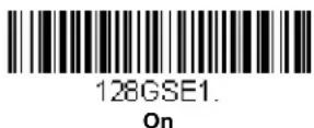
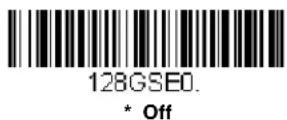
Code 128 Redundancy
If you are encountering errors when reading Code 128 bar codes, you may want to adjust the redundancy count. Redundancy adjusts the number of times a bar code is decoded before transmission, which may reduce the number of errors. Note that the higher the redundancy count, the longer it will take to decode the bar code. To adjust the redundancy, scan the Code 128 Redundancy bar code below, then scan a redundancy count between 0 and 10 on the Programming Chart inside the back cover of this manual. Then scan the Save bar code. Default = 0.

128VOT.
Code 128 Redundancy
Code 128 Message Length
Scan the bar codes below to change the message length. Refer to Message Length Description (page 6-1) for additional information. Minimum and Maximum lengths = 0-80. Minimum Default = 3, Maximum Default = 80.
128MIN.
Minimum Message Length
128MAX
Maximum Message Length
Code 128 Append
This function allows the scanner to append the data from several Code 128 bar codes together before transmitting them to the host computer. When the scanner encounters a Code 128 bar code with the append trigger character(s), it buffers Code 128 bar codes until it reads a Code 128 bar code that does not have the append trigger. The data is then transmitted in the order in which the bar codes were read (FIFO). Default = On.

128APP1
* On

128APP0
Off
ISBT 128 Concatenation
In 1994 the International Society of Blood Transfusion (ISBT) ratified a standard for communicating critical blood information in a uniform manner. The use of ISBT formats requires a paid license. The ISBT 128 Application Specification describes 1) the critical data elements for labeling blood products, 2) the current recommendation to use Code 128 due to its high degree of security and its space-efficient design, 3) a variation of Code 128 that supports concatenation of neighboring symbols, and 4) the standard layout for bar codes on a blood product label. Use the bar codes below to turn concatenation on or off. Default = Off.

ISBENA1.
On

ISBENAD
* Off
Concatenation Timeout
When searching for bar codes during concatenation, you may wish to set a delay used to find the next bar code. Set the length (in milliseconds) for this delay by scanning the following bar code, then setting the timeout (from 1-65535 milliseconds) by scanning digits from the Programming Chart, then scanning Save. Default = 750.

DLYCCT.
Concatenation Timeout
ISBT 128 Predefined Concatenation Sequences
Note: You must enable Code 128 and ISBT 128 to use this feature.
The following bar codes are used to select the pre-defined ISBT 128 Concatenation Sequence you wish to use. Once you have selected the concatenation sequence, use ISBT 128 Predefined Concatenation Sequences On/Off to enable this feature. Default = Donation ID Number (001)
and ABO/RhD Blood Groups (002).

ISBPCSO
* Donation ID Number (001) and ABO/RhD Blood Groups (002)

ISBPCS1
Donation ID Number (001) and Donor ID Number (019)

ISBPCS2
Donation ID Number (001) and
Confidential Unit Exclusion Status

ISBPCS3
Product Code (003) and Expiration Date (Form 1)
ISBPCS4
Product Code (003) and Expiration Date (Form 2)

ISBPCS5
Product Code (003) and Expiration Date (Form 3)

ISBPCS6
Product Code (003) and Expiration Date (Form 4)
ISBT 128 Predefined Concatenation Sequences On/Off
The following selections allow you to enable or require the Predefined ISBT 128 Concatenation Sequences.
If you scan Off, the predefined concatenation sequences are disabled.
If you scan the Allow Predefined Sequence code, then the scanner will output only the data combination specified in the predefined concatenation sequence you selected.
If you scan the Require Predefined Sequence code, the data combination specified in the predefined concatenation sequence you selected is required to transmit the data. No data is output unless the sequence is read.
Default = Off.


ISBT 128 User-Defined Concatenation Sequences
Note: You must enable Code 128 and ISBT 128 to use this feature.
The following bar codes are used to create a custom ISBT 128 Concatenation Sequence. Select the identifiers you want to transmit in the 1st and 2nd positions, both left and right. Refer to the ISBT 128 Standard Technical Specification for the list of data identifiers.
Use the ASCII Conversion Chart (Code Page 1252), page A-2, to find the characters needed for the identifier. Locate the hex value for each character and scan that 2 digit/character value from the Programming Chart inside the back cover of this manual.
Example: You want to create a concatenation sequence that has the Donation Identification Number (001) as the left identifier, and Product Code (003) as the right identifier.
The ISBT Index of Data Structures shows that for the Donation Identification Number, the first character is “=” and the second character can be from A-N; P-Z; 1-9. For this example, use “G.” The Product Code first character is “=” and the second character is “<.”
Step 1. Scan the 1st Left Identifier bar code, below.
Step 2. Use the Programming Chart to scan 3, D (hex for “=”).
Step 3. Scan Save.
Step 4. Scan the 2nd Left Identifier bar code, below.
Step 5. Use the Programming Chart to scan 4, 7 (hex for "G").
Step 6. Scan Save.
Step 7. Scan the 1st Right Identifier bar code, below.
Step 8. Use the Programming Chart to scan 3, D (hex for “=”).
Step 9. Scan Save.
Step 10. Scan the 2nd Right Identifier bar code, below.
Step 11. Use the Programming Chart to scan 3, C (hex for "<").
Step 12. Scan Save.
Once you have programmed the concatenation sequence, use ISBT 128 User-Defined Concatenation Sequences to enable this feature. Default = 0.
ISBUL1
1st Left Identifier

ISBUL2
2nd Left Identifier

ISBUR1
1st Right Identifier

ISBUR2
2nd Right Identifier
ISBT 128 User-Defined Concatenation Sequences On/Off
The following selections allow you to enable or require the User-Defined ISBT 128 Concatenation Sequences.
If you scan Off, the User-Defined concatenation sequences are disabled.
If you scan the Allow User-Defined Sequence code, then the scanner will output only the data combination specified in the User-Defined concatenation sequence you created.
If you scan the Require User-Defined Sequence code, the data combination specified in the User-Defined concatenation sequence is required to transmit the data. No data is output unless the sequence is read.
Default = Off.

ISBUCEO.
* Off
ISBUCE2
Require User-Defined Sequence
Content Verification
When the On bar code is scanned, the check character values are output along with the bar code data, thus allowing you to verify that the check character is in agreement with that calculated for the data stream. Default = Off.

ISBXM01
On

ISBXM00
* Off
Transmit Identifiers
You may disable the transmission of the ISBT Code 128 data identifiers by scanning Off. When this selection is Off, the first 2 data (ID) characters are removed from the data stream unless the ISBT code contains the Donation Identification Number identifiers. If the code contains the Donation Identification Number identifiers, only the first ID character is removed from the Donation Identification Number. The second character is transmitted as normal data. Default = On.

ISBXM11
* On
ISBXM10
Off
Flag Digit Conversion
Type 3 flag digits are a part of the Donation Identification Number in an ISBT 128 bar code. If you select On, the flag data is converted into a single MOD (37, 2) character and transmitted with the bar code data. Scan Off if you do not want the flag digits transmitted. Default = Off.

ISBXM21
On

ISBXM20
* Off
GS1-128

GS1-128 On/Off
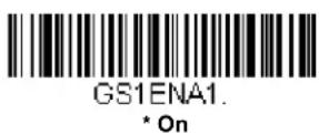
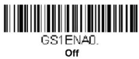
GS1-128 Application Identifier Parsing
This allows a single GS1-128 bar code to be broken into multiple transmissions based on the presence of application identifiers (AI) embedded in the bar code. To use this feature, first enable 128 Group Separator Output (page 6-17). Next, scan Transmit Without Identifiers if you want the bar code broken into packets and stripped of the AI. If you want the AI included, scan Transmit With Identifiers. Default = Off.
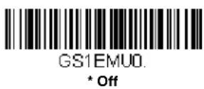


GS1-128 Redundancy
If you are encountering errors when reading GS1-128 bar codes, you may want to adjust the redundancy count. Redundancy adjusts the number of times a bar code is decoded before transmission, which may reduce the number of errors. Note that the higher the redundancy count, the longer it will take to decode the bar code. To adjust the redundancy, scan the GS1-128 Redundancy bar code below, then scan a redundancy count between 0 and 10 on the Programming Chart inside the back cover of this manual. Then scan the Save bar code. Default = 0.
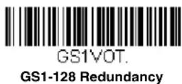
GS1-128 Message Length
Scan the bar codes below to change the message length. Refer to Message Length Description (page 6-1) for additional information. Minimum and Maximum lengths = 1-80. Minimum Default = 3, Maximum Default = 80.

GS1MIN.
Minimum Message Length
GS1MAX
Maximum Message Length
Telepen

TELDFT.
Telepen On/Off
TELENA1.
On
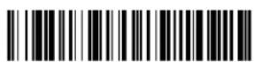
TELENAD.
* Off
Telepen Output
Using AIM Telepen Output, the scanner reads symbols with start/stop pattern 1 and decodes them as standard full ASCII (start/stop pattern 1). When Original Telepen Output is selected, the scanner reads symbols with start/stop pattern 1 and decodes them as compressed numeric with optional full ASCII (start/stop pattern 2). Default = AIM Telepen Output.

TELOLDO
* AIM Telepen Output

TELOLD1.
Original Telepen Output
Telepen Redundancy
If you are encountering errors when reading Telepen bar codes, you may want to adjust the redundancy count. Redundancy adjusts the number of times a bar code is decoded before transmission, which may reduce the number of errors. Note that the higher the redundancy count, the longer it will take to decode the bar code. To adjust the redundancy, scan the Telepen Redundancy bar code below, then scan a redundancy count between 0 and 10 on the Programming Chart inside the back cover of this manual. Then scan the Save bar code. Default = 0.

TELVOT.
Telepen Redundancy
Telepen Message Length
Scan the bar codes below to change the message length. Refer to Message Length Description (page 6-1) for additional information. Minimum and Maximum lengths = 1-80. Minimum Default = 3, Maximum Default = 80.

TELMIN
Minimum Message Length

TELMAX
Maximum Message Length
UPC-A

UPADFT.
UPC-A On/Off

UPBENA1.
* On

UPBENAD.
Off
Note: To convert UPC-A bar codes to EAN-13, see Convert UPC-A to EAN-13 on page 6-34.
UPC-A Check Digit
This selection allows you to specify whether the check digit should be transmitted at the end of the scanned data or not. Default = On.


UPC-A Number System
The numeric system digit of a U.P.C. symbol is normally transmitted at the beginning of the scanned data, but the unit can be programmed so it will not transmit it. Default = On.
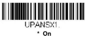

UPC-A Addenda
This selection adds 2 or 5 digits to the end of all scanned UPC-A data. Default = Off for both 2 Digit and 5 Digit Addenda.


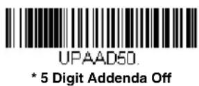
UPC-A Addenda Required
When Required is scanned, the scanner will only read UPC-A bar codes that have addenda. You must then turn on a 2 or 5 digit addenda listed on page 6-26. Default = Not Required.


UPC-A Addenda Separator
When this feature is on, there is a space between the data from the bar code and the data from the addenda. When turned off, there is no space. Default = On.


Addenda Timeout
You can set a time during which the scanner looks for a coupon code. If a coupon code is not found within this time period, the data can be either transmitted or discarded, based on the setting you are using for UPC-A/EAN-13 with Extended Coupon Code or UPC-A Number System 4 Addenda Required. Set the length (in milliseconds) for this timeout by scanning the bar code below, then setting the timeout (from 0-65535 milliseconds) by scanning digits from the Programming Chart, then scanning Save. Default = 100.
Note: The Addenda Timeout setting is applied to all addenda and coupon code searches.

UPC-A Redundancy
If you are encountering errors when reading UPC-A bar codes, you may want to adjust the redundancy count. Redundancy adjusts the number of times a bar code is decoded before transmission, which may reduce the number of errors. Note that the higher the redundancy count, the longer it will take to decode the bar code. To adjust the redundancy, scan the UPC-A Redundancy bar code below, then scan a redundancy count between 0 and 10 on the Programming Chart inside the back cover of this manual. Then scan the Save bar code. Default = 0.

UPC-A/EAN-13
with Extended Coupon Code
Use the following codes to enable or disable UPC-A and EAN-13 with Extended Coupon Code. When left on the default setting (Off), the scanner treats Coupon Codes and Extended Coupon Codes as single bar codes.
If you scan the Allow Concatenation code, when the scanner sees the coupon code and the extended coupon code in a single scan, it transmits both as separate symbologies. Otherwise, it transmits the first coupon code it reads.
If you scan the Require Concatenation code, the scanner must see and read the coupon code and extended coupon code in a single read to transmit the data. No data is output unless both codes are read. Default = Off.

CPNENAD.
* Off

CPNENA1.
Allow Concatenation

CPNENA2.
Require Concatenation
UPC-A/Code 128 Coupon Code Output
These settings are used when a coupon code and a Code 128 bar code are detected in the same scan. Scan Multiple Code Output to transmit both codes as separate bar codes with separate terminators. Scan Single Code Output to transmit the data as one extended bar code. Default = Multiple Code Output.

CPNSTYO
* Multiple Code Output

CPNSTY1
Single Code Output
UPC-A Number System 4 Addenda Required
This setting programs the scanner to require a coupon code only on UPC-A bar codes that begin with a "4." The following settings can be programmed:
Require Coupon Code: All UPC-A bar codes that begin with a "4" must have a coupon code. The UPC-A bar code with the coupon code is then transmitted as a single, concatenated bar code. If a coupon code is not found within the Addenda Timeout period, the UPC-A bar code is discarded.
Don't Require Coupon Code: If you have selected Require Coupon Code, and you want to disable this feature, scan Don't Require Coupon Code. UPC-A bar codes are transmitted, depending on the setting you are using for UPC-A/EAN-13 with Extended Coupon Code.
Default = Don't Require Coupon Code.
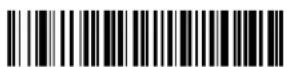
ARQSY40.
* Don't Require Coupon Code

ARQSY41.
Require Coupon Code
UPC-A Number System 5 Addenda Required
This setting programs the scanner to require any combination of a coupon code, a 2 digit addenda, or a 5 digit addenda on UPC-A bar codes that begin with a "5." The following settings can be programmed:
Require Coupon Code/Addenda: All UPC-A bar codes that begin with a "5" must have a coupon code, a 2 digit addenda, a 5 digit addenda, or a combination of these addenda. The UPC-A bar code with the coupon code and/or addenda is then transmitted as a single, concatenated bar code. If a coupon code and/or required addenda is not found within the Addenda Timeout period, the UPC-A bar code is discarded.
Don't Require Coupon Code/Addenda: If you have selected Require Coupon Code/Addenda, and you want to disable this feature, scan Don't Require Coupon Code/Addenda. UPC-A bar codes are transmitted, depending on the setting you are using for UPC-A/EAN-13 with Extended Coupon Code.
Default = Don't Require Coupon Code/Addenda.

ARQSY50.
* Don't Require Coupon Code/Addenda

ARQSY51.
Require 2 Digit Addenda

ARQSY52.
Require 5 Digit Addenda

ARQSY53.
Require 2 or 5 Digit Addenda

ARQSY54.
Require Coupon Code

ARQSY55
Require Coupon Code or 2 Digit Addenda

ARQSY56.
Require Coupon Code or 5 Digit Addenda

ARQSY57
Require Coupon Code, 2 Digit
Addenda, or 5 Digit Addenda
Addenda Timeout
You can set a time during which the scanner looks for a coupon code. If a coupon code is not found within this time period, the data can be either transmitted or discarded, based on the setting you are using for UPC-A/EAN-13 with Extended Coupon Code or UPC-A Number System 4 Addenda Required. Set the length (in milliseconds) for this timeout by scanning the bar code below, then setting the timeout (from 0-65535 milliseconds) by scanning digits from the Programming Chart, then scanning Save. Default = 100.
Note: The Addenda Timeout setting is applied to all addenda and coupon code searches.

DLYADD
Addenda Timeout
Coupon GS1 DataBar Output
If you scan coupons that have both UPC and GS1 DataBar codes, you may wish to scan and output only the data from the GS1 DataBar code. Scan the GS1 Output On code below to scan and output only the GS1 DataBar code data. Default = GS1 Output Off.

CPNGS10.
* GS1 Output Off

CPNGS11.
GS1 Output On
Addenda Timeout
You can set a time during which the scanner looks for a coupon code. If a coupon code is not found within this time period, the data can be either transmitted or discarded, based on the setting you are using for UPC-A/EAN-13 with Extended Coupon Code or UPC-A Number System 4 Addenda Required. Set the length (in milliseconds) for this timeout by scanning the bar code below, then setting the timeout (from 0-65535 milliseconds) by scanning digits from the Programming Chart, then scanning Save. Default = 100.
Note: The Addenda Timeout setting is applied to all addenda and coupon code searches.

DLYADD.
Addenda Timeout
UPC-E0

UPC-E0 On/Off
Most U.P.C. bar codes lead with the 0 number system. To read these codes, use the UPC-E0 On selection. Default = On.


UPC-E0 Expand
UPC-E Expand expands the UPC-E code to the 12 digit, UPC-A format. Default = Off.


UPC-E0 Number System
The numeric system digit of a UPC-A symbol is normally transmitted at the beginning of scanned data. When using UPC-E Expand, the unit can be programmed so it will not transmit it. Default = On.


UPC-E0 Number System and Check Digit
UPC-E0 sample showing the number system and check digit:
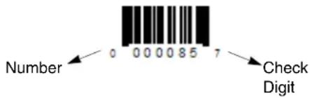
UPC-E0 Addenda Required
When Required is scanned, the scanner will only read UPC-E bar codes that have addenda. Default = Not Required.


UPC-E0 Addenda Separator
When this feature is On, there is a space between the data from the bar code and the data from the addenda. When turned Off, there is no space. Default = Off.


UPC-E0 Check Digit
Check Digit specifies whether the check digit should be transmitted at the end of the scanned data or not. Default = Off.


UPC-E0 Leading Zero
This feature allows the transmission of a leading zero (0) at the beginning of scanned data. To prevent transmission, scan Off. Default = Off.


UPC-E0 Addenda
This selection adds 2 or 5 digits to the end of all scanned UPC-E data. Default = Off for both 2 Digit and 5 Digit Addenda.



UPC-E0 Redundancy
If you are encountering errors when reading UPC-E0 bar codes, you may want to adjust the redundancy count. Redundancy adjusts the number of times a bar code is decoded before transmission, which may reduce the number of errors. Note that the higher the redundancy count, the longer it will take to decode the bar code. To adjust the redundancy, scan the UPC-E0 Redundancy bar code below, then scan a redundancy count between 0 and 10 on the Programming Chart inside the back cover of this manual. Then scan the Save bar code. Default = 1.

EAN/JAN-13
EAN/JAN-13 On/Off

* On

Convert UPC-A to EAN-13
When UPC-A Converted to EAN-13 is selected, UPC-A bar codes are converted to 13 digit EAN-13 codes by adding a zero to the front. When Do not Convert UPC-A is selected, UPC-A codes are read as UPC-A. Default = Do not Convert UPC-A.

UPC-A Converted to EAN-13

EAN/JAN-13 Check Digit
This selection allows you to specify whether the check digit should be transmitted at the end of the scanned data or not. Default = On.


EAN/JAN-13 Addenda
This selection adds 2 or 5 digits to the end of all scanned EAN/JAN-13 data. Default = Off for both 2 Digit and 5 Digit Addenda.

E13AD21
2 Digit Addenda On
E13AD20
* 2 Digit Addenda Off

E13AD51
5 Digit Addenda On

E13AD50
* 5 Digit Addenda Off
EAN/JAN-13 Addenda Required
When Required is scanned, the scanner will only read EAN/JAN-13 bar codes that have addenda. Default = Not Required.

E13ARQ1
Required

E13ARQ0
* Not Required
EAN-13 Beginning with 2 Addenda Required
This setting programs the scanner to require a 2 digit addenda only on EAN-13 bar codes that begin with a "2." The following settings can be programmed:
Require 2 Digit Addenda: All EAN-13 bar codes that begin with a "2" must have a 2 digit addendum. The EAN-13 bar code with the 2 digit addendum is then transmitted as a single, concatenated bar code. If a 2 digit addendum is not found within the Addenda Timeout period, the EAN-13 bar code is discarded.
Note: if you are using EAN-13 Beginning with 290 Addenda Required (page 6-36), that setting will take precedence over this one.
Don't Require 2 Digit Addenda: If you have selected Require 2 Digit Addenda, and you want to disable this feature, scan Don't Require 2 Digit Addenda. EAN-13 bar codes are transmitted, depending on the setting you are using for EAN/ JAN-13 Addenda Required.
Default = Don't Require 2 Digit Addenda.

ARQSY20.
* Don't Require 2 Digit Addenda
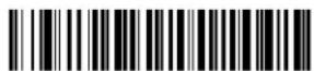
ARQSY21
Require 2 Digit Addenda
EAN-13 Beginning with 290 Addenda Required
This setting programs the scanner to require a 5 digit addenda only on EAN-13 bar codes that begin with “290.” The following settings can be programmed:
Require 5 Digit Addenda: All EAN-13 bar codes that begin with "290" must have a 5 digit addendum. The EAN-13 bar code with the 5 digit addendum is then transmitted as a single, concatenated bar code. If a 5 digit addendum is not found within the Addenda Timeout period, the EAN-13 bar code is discarded.
Note: if you are using EAN-13 Beginning with 2 Addenda Required (page 6-35), this setting will take precedence.
Don't Require 5 Digit Addenda: If you have selected Require 5 Digit Addenda, and you want to disable this feature, scan Don't Require 5 Digit Addenda. EAN-13 bar codes are transmitted, depending on the setting you are using for EAN/JAN-13 Addenda Required.
Default = Don't Require 5 Digit Addenda.

ARQ2900
* Don't Require 5 Digit Addenda

ARQ2901
Require 5 Digit Addenda
EAN-13 Beginning with 378/379 Addenda Required
This setting programs the scanner to require any combination of a 2 digit addenda or a 5 digit addenda on EAN-13 bar codes that begin with a "378" or "379." The following settings can be programmed:
Require Addenda: All EAN-13 bar codes that begin with a "378" or "379" must have a 2 digit addenda, a 5 digit addenda, or a combination of these addenda. The EAN-13 bar code with the addenda is then transmitted as a single, concatenated bar code. If the required addenda is not found within the Addenda Timeout period, the EAN-13 bar code is discarded.
Don't Require Addenda: If you have selected Require Addenda, and you want to disable this feature, scan Don't Require Addenda. EAN-13 bar codes are transmitted, depending on the setting you are using for EAN/JAN-13 Addenda Required.
Default = Don't Require Addenda.

ARQ3780
* Don't Require Addenda

ARQ3782.
Require 5 Digit Addenda
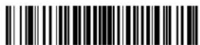
ARQ3781
Require 2 Digit Addenda

ARQ3783.
Require 2 or 5 Digit Addenda
EAN-13 Beginning with 414/419 Addenda Required
This setting programs the scanner to require any combination of a 2 digit addenda or a 5 digit addenda on EAN-13 bar codes that begin with a "414" or "419." The following settings can be programmed:
Require Addenda: All EAN-13 bar codes that begin with a "414" or "419" must have a 2 digit addenda, a 5 digit addenda, or a combination of these addenda. The EAN-13 bar code with the addenda is then transmitted as a single, concatenated bar code. If the required addenda is not found within the Addenda Timeout period, the EAN-13 bar code is discarded.
Don't Require Addenda: If you have selected Require Addenda, and you want to disable this feature, scan Don't Require Addenda. EAN-13 bar codes are transmitted, depending on the setting you are using for EAN/JAN-13 Addenda Required.
Default = Don't Require Addenda.

ARQ4140
* Don't Require Addenda

ARQ4141
Require 2 Digit Addenda
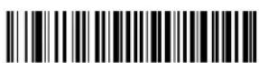
ARQ4142
Require 5 Digit Addenda

ARQ4143
Require 2 or 5 Digit Addenda
EAN-13 Beginning with 434/439 Addenda Required
This setting programs the scanner to require any combination of a 2 digit addenda or a 5 digit addenda on EAN-13 bar codes that begin with a “434” or “439.” The following settings can be programmed:
Require Addenda: All EAN-13 bar codes that begin with a "434" or "439" must have a 2 digit addenda, a 5 digit addenda, or a combination of these addenda. The EAN-13 bar code with the addenda is then transmitted as a single, concatenated bar code. If the required addenda is not found within the Addenda Timeout period, the EAN-13 bar code is discarded.
Don't Require Addenda: If you have selected Require Addenda, and you want to disable this feature, scan Don't Require Addenda. EAN-13 bar codes are transmitted, depending on the setting you are using for EAN/JAN-13 Addenda Required.
Default = Don't Require Addenda.

ARQ4340.
* Don't Require Addenda

ARQ4341
Require 2 Digit Addenda

ARQ4342
Require 5 Digit Addenda

ARQ4343
Require 2 or 5 Digit Addenda
EAN-13 Beginning with 977 Addenda Required
This setting programs the scanner to require a 2 digit addenda only on EAN-13 bar codes that begin with "977." The following settings can be programmed:
Require 2 Digit Addenda: All EAN-13 bar codes that begin with "977" must have a 2 digit addendum. The EAN-13 bar code with the 2 digit addendum is then transmitted as a single, concatenated bar code. If a 2 digit addendum is not found within the Addenda Timeout period, the EAN-13 bar code is discarded.
Don't Require 2 Digit Addenda: If you have selected Require 2 Digit Addenda, and you want to disable this feature, scan Don't Require 2 Digit Addenda. EAN-13 bar codes are transmitted, depending on the setting you are using for EAN/JAN-13 Addenda Required.
Default = Don't Require 2 Digit Addenda.

ARQ9770.
* Don't Require 2 Digit Addenda

ARQ9771
Require 2 Digit Addenda
EAN-13 Beginning with 978 Addenda Required
These settings program the scanner to require a 5 digit addenda only on EAN-13 bar codes that begin with "978." The following settings can be programmed:
Require 5 Digit Addenda: All EAN-13 bar codes that begin with "978" must have a 5 digit addendum. The EAN-13 bar code with the 5 digit addendum is then transmitted as a single, concatenated bar code. If a 5 digit addendum is not found within the Addenda Timeout period, the EAN-13 bar code is discarded.
Don't Require 5 Digit Addenda: If you have selected Require 5 Digit Addenda, and you want to disable this feature, scan Don't Require 5 Digit Addenda. EAN-13 bar codes are transmitted, depending on the setting you are using for EAN/ JAN-13 Addenda Required.
Default = Don't Require 5 Digit Addenda.

* Don't Require 5 Digit Addenda
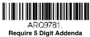
EAN-13 Beginning with 979 Addenda Required
These settings program the scanner to require a 5 digit addenda only on EAN-13 bar codes that begin with "979." The following settings can be programmed:
Require 5 Digit Addenda: All EAN-13 bar codes that begin with "979" must have a 5 digit addendum. The EAN-13 bar code with the 5 digit addendum is then transmitted as a single, concatenated bar code. If a 5 digit addendum is not found within the Addenda Timeout period, the EAN-13 bar code is discarded.
Don't Require 5 Digit Addenda: If you have selected Require 5 Digit Addenda, and you want to disable this feature, scan Don't Require 5 Digit Addenda. EAN-13 bar codes are transmitted, depending on the setting you are using for EAN/JAN-13 Addenda Required.
Default = Don't Require 5 Digit Addenda.
* Don't Require 5 Digit Addenda
EAN/JAN-13 Addenda Separator
When this feature is On, there is a space between the data from the bar code and the data from the addenda. When turned Off, there is no space. Default = Off.

Note: If you want to enable or disable EAN13 with Extended Coupon Code, refer to UPC-A/EAN-13 with Extended Coupon Code (page 6-27).
Addenda Timeout
You can set a time during which the scanner looks for a coupon code. If a coupon code is not found within this time period, the data can be either transmitted or discarded, based on the setting you are using for UPC-A/EAN-13 with Extended Coupon Code or UPC-A Number System 4 Addenda Required. Set the length (in milliseconds) for this timeout by scanning the bar code below, then setting the timeout (from 0-65535 milliseconds) by scanning digits from the Programming Chart, then scanning Save. Default = 100.
Note: The Addenda Timeout setting is applied to all addenda and coupon code searches.

DLYADD.
Addenda Timeout
EAN/JAN-13 Redundancy
If you are encountering errors when reading EAN/JAN-13 bar codes, you may want to adjust the redundancy count. Redundancy adjusts the number of times a bar code is decoded before transmission, which may reduce the number of errors. Note that the higher the redundancy count, the longer it will take to decode the bar code. To adjust the redundancy, scan the EAN/JAN-13 Redundancy bar code below, then scan a redundancy count between 0 and 10 on the Programming Chart inside the back cover of this manual. Then scan the Save bar code. Default = 0.

E13VOT.
EAN/JAN-13 Redundancy
ISBN Translate
When On is scanned, EAN-13 Bookland symbols are translated into their equivalent ISBN number format. Default = Off.

E13ISB1.
On
E13ISB0
* Off
Convert ISBN to 13-Digit
When translating EAN-13 codes to the ISBN format, you can convert the bar code to a 13 digit format by scanning the Convert to 13-Digit On bar code below. Default = Convert to 13-Digit Off.

E13|131
Convert to 13-Digit On

E13I130.
*Convert to 13-Digit Off
ISBN Reformat
In normal use, the first two or three digits of an EAN-13 bar code identify the country of origin. The country prefixes are 978 and 979. To reformat ISBN codes so the country prefix is dropped out, scan the Reformat On bar code below. Default = Reformat Off.

ISSN Translate
When On is scanned, EAN-13 977 Bookland symbols are translated into their equivalent 8-digit ISSN number format. For example, 9770123456787 will be transmitted as 01234560. Default = Off.
ISSN Reformat
When Reformat On is scanned, EAN-13 977 Bookland symbols are translated into their equivalent 8-digit ISSN number format, with hyphens added to the output. For example, 9770123456787 will be transmitted as 0123-456-0. (You must first scan ISSN On (page 6-41) before scanning Reformat On.) Default = Reformat Off.


EAN/JAN-8

EAN/JAN-8 On/Off

EAN/JAN-8 Check Digit
This selection allows you to specify whether the check digit should be transmitted at the end of the scanned data or not. Default = On.

EAN/JAN-8 Addenda
This selection adds 2 or 5 digits to the end of all scanned EAN/JAN-8 data. Default = Off for both 2 Digit and 5 Digit Addenda.


EA8AD50.
* 5 Digit Addenda Off
EAN/JAN-8 Addenda Required
When Required is scanned, the scanner will only read EAN/JAN-8 bar codes that have addenda. Default = Not Required.
EA8ARQ1
Required

EABARQO.
* Not Required
EAN/JAN-8 Addenda Separator
When this feature is On, there is a space between the data from the bar code and the data from the addenda. When turned Off, there is no space. Default = Off.

EA8ADS1
On

EABADSO
* Off
Addenda Timeout
You can set a time during which the scanner looks for a coupon code. If a coupon code is not found within this time period, the data can be either transmitted or discarded, based on the setting you are using for UPC-A/EAN-13 with Extended Coupon Code or UPC-A Number System 4 Addenda Required. Set the length (in milliseconds) for this timeout by scanning the bar code below, then setting the timeout (from 0-65535 milliseconds) by scanning digits from the Programming Chart, then scanning Save. Default = 100.
Note: The Addenda Timeout setting is applied to all addenda and coupon code searches.

DLYADD
Addenda Timeout
EAN/JAN-8 Redundancy
If you are encountering errors when reading EAN/JAN-8 bar codes, you may want to adjust the redundancy count. Redundancy adjusts the number of times a bar code is decoded before transmission, which may reduce the number of errors. Note that the higher the redundancy count, the longer it will take to decode the ba code. To adjust the redundancy, scan the EAN/JAN-8 Redundancy bar code below, then scan a redundancy count between 0 and 10 on the Programming Chart inside the back cover of this manual. Then scan the Save bar code. Default = 0.

EA8VOT.
EAN/JAN-8 Redundancy
MSI

MSIDFT
MSI On/Off

MSIENA1
On
MSIENAD.
* Off
MSI Check Character
Different types of check characters are used with MSI bar codes. You can program the scanner to read MSI bar codes with Type 10 check characters. Default = Validate Type 10, but Don't Transmit.
When Check Character is set to Validate Type 10/11 and Transmit, the scanner will only read MSI bar codes printed with the specified type check character(s), and will transmit the character(s) at the end of the scanned data.
When Check Character is set to Validate Type 10/11, but Don't Transmit, the unit will only read MSI bar codes printed with the specified type check character(s), but will not transmit the check character(s) with the scanned data.

MSICHKO
* Validate Type 10, but Don't Transmit
MSICHK1
Validate Type 10 and Transmit

MSICHK2.
Validate 2 Type 10 Characters, but Don't Transmit

MSICHK3
Validate 2 Type 10 Characters and Transmit

MSICHK4
Validate Type 10 then Type 11 Character, but Don't Transmit

MSICHK5.
Validate Type 10 then
Type 11 Character and Transmit

MSICHK6
Disable MSI Check Characters
MSI Redundancy
If you are encountering errors when reading MSI bar codes, you may want to adjust the redundancy count. Redundancy adjusts the number of times a bar code is decoded before transmission, which may reduce the number of errors. Note that the higher the redundancy count, the longer it will take to decode the bar code. To adjust the redundancy, scan the MSI Redundancy bar code below, then scan a redundancy count between 0 and 10 on the Programming Chart inside the back cover of this manual. Then scan the Save bar code. Default = 0.

MSIVOT
MSI Redundancy
MSI Message Length
Scan the bar codes below to change the message length. Refer to Message Length Description (page 6-1) for additional information. Minimum and Maximum lengths = 1-80. Minimum Default = 3, Maximum Default = 80.

MSIMIN.
Minimum Message Length

MSIMAX
Maximum Message Length
Plessey Code
< Default All Plessey Code Settings >

Plessey Code On/Off


Plessey Check Character
No Check Character indicates that the scanner reads and transmits bar code data with or without a check character.
When Check Character is set to Validate, but Don't Transmit, the unit only reads Plessey bar codes printed with a check character, but will not transmit the check character with the scanned data.
When Check Character is set to Validate and Transmit, the scanner only reads Plessey bar codes printed with a check character, and will transmit this character at the end of the scanned data. Default = No Check Character.


Plessey Redundancy
If you are encountering errors when reading Plessey bar codes, you may want to adjust the redundancy count. Redundancy adjusts the number of times a bar code is decoded before transmission, which may reduce the number of errors. Note that the higher the redundancy count, the longer it will take to decode the bar code. To adjust the redundancy, scan the Plessey Redundancy bar code below, then scan a redundancy count between 0 and 10 on the Programming Chart inside the back cover of this manual. Then scan the Save bar code. Default = 0.

Plessey Message Length
Scan the bar codes below to change the message length. Refer to Message Length Description (page 6-1) for additional information. Minimum and Maximum lengths = 1-80. Minimum Default = 3, Maximum Default = 80.

PLSMIN.
Minimum Message Length

PLSMAX
Maximum Message Length
GS1 DataBar Omnidirectional
< Default All GS1 DataBar Omnidirectional Settings >

RSSDFT.
GS1 DataBar Omnidirectional On/Off
RSSENA1
* On
RSSENAD
Off
GS1 DataBar Omnidirectional Redundancy
If you are encountering errors when reading GS1 DataBar Omnidirectional bar codes, you may want to adjust the redundancy count. Redundancy adjusts the number of times a bar code is decoded before transmission, which may reduce the number of errors. Note that the higher the redundancy count, the longer it will take to decode the bar code. To adjust the redundancy, scan the GS1 DataBar Omnidirectional Redundancy bar code below, then scan a redundancy count between 0 and 10 on the Programming Chart inside the back cover of this manual. Then scan the Save bar code. Default = 0.

RSSVOT.
GS1 DataBar Omnidirectional
Redundancy
GS1 DataBar Limited
< Default All GS1 DataBar Limited Settings >

GS1 DataBar Limited On/Off
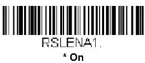

GS1 DataBar Limited Redundancy
If you are encountering errors when reading GS1 DataBar Limited bar codes, you may want to adjust the redundancy count. Redundancy adjusts the number of times a bar code is decoded before transmission, which may reduce the number of errors. Note that the higher the redundancy count, the longer it will take to decode the bar code. To adjust the redundancy, scan the GS1 DataBar Limited Redundancy bar code below, then scan a redundancy count between 0 and 10 on the Programming Chart inside the back cover of this manual. Then scan the Save bar code. Default = 0.
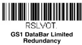
GS1 DataBar Expanded
< Default All GS1 DataBar Expanded Settings >

GS1 DataBar Expanded On/Off
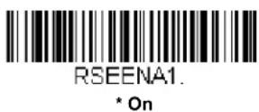

GS1 DataBar Expanded Redundancy
If you are encountering errors when reading GS1 DataBar Expanded bar codes, you may want to adjust the redundancy count. Redundancy adjusts the number of times a bar code is decoded before transmission, which may reduce the number of errors. Note that the higher the redundancy count, the longer it will take to decode the bar code. To adjust the redundancy, scan the GS1 DataBar Expanded Redundancy bar code below, then scan a redundancy count between 0 and 10 on the Programming Chart inside the back cover of this manual. Then scan the Save bar code. Default = 0.

GS1 DataBar Expanded Message Length
Scan the bar codes below to change the message length. Refer to Message Length Description (page 6-1) for additional information. Minimum and Maximum lengths = 1-80. Minimum Default = 3, Maximum Default = 80.

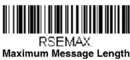
Trioptic Code
Note: If you are going to scan Code 32 Pharmaceutical codes (page 6-6), Trioptic Code must be off.
Trioptic Code is used for labeling magnetic storage media.

GS1 Emulation
The scanner can automatically format the output from any GS1 data carrier to emulate what would be encoded in an equivalent GS1-128 or GS1 DataBar symbol. GS1 data carriers include UPC-A and UPC-E, EAN-13 and EAN-8, ITF-14, GS1-128, and GS1-128 DataBar and GS1 Composites. (Any application that accepts GS1 data can be simplified since it only needs to recognize one data carrier type.)
If GS1-128 Emulation is scanned, all retail codes (U.P.C., UPC-E, EAN8, EAN13) are expanded out to 16 digits. If the AIM ID is enabled, the value will be the GS1-128 AIM ID, ]C1 (see Symbology Charts on page A-1).
If GS1 DataBar Emulation is scanned, all retail codes (U.P.C., UPC-E, EAN8, EAN13) are expanded out to 16 digits. If the AIM ID is enabled, the value will be the GS1-DataBar AIM ID, ]em (see Symbology Charts on page A-1).
If GS1 Code Expansion Off is scanned, retail code expansion is disabled, and UPC-E expansion is controlled by the UPC-E0 Expand (page 6-31) setting. If the AIM ID is enabled, the value will be the GS1-128 AIM ID, ]C1 (see Symbology Charts on page A-1).
If EAN8 to EAN13 Conversion is scanned, all EAN8 bar codes are converted to EAN13 format.
Default = GS1 Emulation Off.


China Post (Hong Kong 2 of 5)
China Post (Hong Kong 2 of 5) On/Off

China Post (Hong Kong 2 of 5) Redundancy
If you are encountering errors when reading China Post (Hong Kong 2 of 5) bar codes, you may want to adjust the redundancy count. Redundancy adjusts the number of times a bar code is decoded before transmission, which may reduce the number of errors. Note that the higher the redundancy count, the longer it will take to decode the bar code. To adjust the redundancy, scan the China Post (Hong Kong 2 of 5) Redundancy bar code below, then scan a redundancy count between 0 and 10 on the Programming Chart inside the back cover of this manual. Then scan the Save bar code. Default = 0.

China Post (Hong Kong 2 of 5) Message Length
Scan the bar codes below to change the message length. Refer to Message Length Description (page 6-1) for additional information. Minimum and Maximum lengths = 1-80. Minimum Default = 3, Maximum Default = 80.

To Add a Test Code I.D. Prefix to All Symbologies
This selection allows you to turn on transmission of a Code I.D. before the decoded symbology. (See the Symbology Charts, beginning on page A-1) for the single character code that identifies each symbology.) This action first clears all current prefixes, then programs a Code I.D. prefix for all symbologies. This is a temporary setting that will be removed when the unit is power cycled.

PRECA2.BK2995C80!
Add Code I.D. Prefix to
All Symbologies (Temporary)
Show Software Revision
Scan the bar code below to output the current software revision, unit serial number, and other product information for the scanner.

REVINF
Show Software Revision
Show Data Format
Scan the bar code below to show current data format settings.
DFMBK3?
Data Format Settings
Test Menu
When you scan the Test Menu On code, then scan a programming code in this manual, the scanner displays the content of a programming code. The programming function will still occur, but in addition, the content of that programming code is output to the terminal.
Note: This feature should not be used during normal scanner operation.

TSTMNU1
On

TSTMNUO
* Off
TotalFreedom
TotalFreedom is an open system architecture that makes it possible for you create applications that reside on your scanner. Decoding apps and Data Formatting apps can be created using TotalFreedom. For further information about TotalFreedom, go to our website at www.honeywellaidc.com.
Application Plug-Ins (Apps)
Any apps that you are using can be turned off or on by scanning the following bar codes. Apps are stored in groups: Decoding, and Formatting. You can enable and disable these groups of apps by scanning that group's On or Off bar code below. You can also scan the List Apps bar code to output a list of all your apps.

PLGDCE1.
* Decoding Apps On
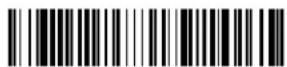
PLGDCEO.
Decoding Apps Off

PLGFOE1
* Formatting Apps On
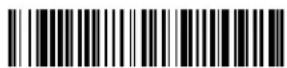
PLGFOED.
Formatting Apps Off

PLGINF
List Apps
Note: You must reset your device in order for the apps setting to take effect.
EZConfig-Scanning Introduction
EZConfig-Scanning provides a wide range of PC-based programming functions that can be performed on a scanner connected to your PC's COM port. EZConfig-Scanning allows you to download upgrades to the scanner's firmware, change programmed parameters, and create and print programming bar codes. Using EZConfig-Scanning, you can even save/open the programming parameters for a scanner. This saved file can be e-mailed or, if required, you can create a single bar code that contains all the customized programming parameters and mail or fax that bar code to any location. Users in other locations can scan the bar code to load in the customized programming.
To communicate with a scanner, EZConfig-Scanning requires that the PC have at least one available serial communication port, or a serial port emulation using a physical USB port. If you are using the serial port and RS232 cable, an external power supply is required.
EZConfig-Scanning Operations
The EZConfig-Scanning software performs the following operations:
Scan Data
Scan Data allows you to scan bar codes and display the bar code data in a window. Scan Data lets you send serial commands to the scanner and receive scanner response that can be seen in the Scan Data window. The data displayed in the Scan Data window can either be saved in a file or printed.
Configure
Configure displays the programming and configuration data of the scanner. The scanner's programming and configuration data is grouped into different categories. Each category is displayed as a tree item under the "Configure" tree node in the application explorer. When one of these tree nodes is clicked, the right-hand side is loaded with the parameters' form belonging to that particular category. The "Configure" tree option has all the programming and configuration parameters specified for a scanner. You can set or modify these parameters as required. You can later write the modified settings to the scanner, or save them to a dcf file.
Installing EZConfig-Scanning from the Web
Note: EZConfig-Scanning requires .NET software. If .NET is not installed on your PC, you will be prompted to install it during the EZConfig-Scanning installation.
- Access the Honeywell web site at www.honeywellaidc.com
- Click on the Resources tab. Select Software.
- Click on the dropdown for Select Product Number. Click on your product number.
- Click on the listing for EZConfig-Scanning.
- When prompted, select Save File, and save the files to the c:\windows\temp directory.
- Once you have finished downloading the file, exit the web site.
- Using Explorer, go to the c:\windows\temp file.
- Double click on the Setup.exe file. Follow the screen prompts to install the EZConfig-Scanning program.
- If you've selected the defaults during installation, you can click on Start Menu-All Programs-Honeywell-EZConfig-Scanning.
Resetting the Factory Defaults

This selection erases all your settings and resets the scanner to the original factory defaults. It also disables all plugins.
If you aren't sure what programming options are in your scanner, or you've changed some options and want to restore the scanner to factory default settings, first scan the Remove Custom Defaults bar code, then scan Activate Defaults. This resets the scanner to the factory default settings.

DEFOVR
Remove Custom Defaults

DEFAULT
Activate Defaults
The Menu Commands, beginning on page 8-4 list the factory default settings for each of the commands (indicated by an asterisk (*) on the programming pages).
Serial Programming Commands
The serial programming commands can be used in place of the programming bar codes. Both the serial commands and the programming bar codes will program the scanner. For complete descriptions and examples of each serial programming command, refer to the corresponding programming bar code in this manual.
The device must be set to an RS232 interface (see page 2-1). The following commands can be sent via a PC COM port using terminal emulation software.
Conventions
The following conventions are used for menu and query command descriptions:
parameterA label representing the actual value you should send as part of a command.
[option] An optional part of a command.
{Data} Alternatives in a command.
bold Names of menus, menu commands, buttons, dialog boxes, and windows that appear on the screen.
Menu Command Syntax
Menu commands have the following syntax (spaces have been used for clarity only):
Prefix[:Name:] Tag SubTag {Data} [, SubTag {Data}] [; Tag SubTag {Data}] [...] Storage
Prefix Three ASCII characters: SYN M CR (ASCII 22,77,13).
Tag A 3 character case-insensitive field that identifies the desired menu command group. For example, all RS232 configuration settings are identified with a Tag of 232.
SubTag A 3 character case-insensitive field that identifies the desired menu command within the tag group. For example, the SubTag for the RS232 baud rate is BAD.
Data The new value for a menu setting, identified by the Tag and SubTag.
Storage A single character that specifies the storage table to which the command is applied. An exclamation point (!) performs the command's operation on the device's volatile menu configuration table. A period (.) performs the command's operation on the device's non-volatile menu configuration table. Use the non-volatile table only for semi-permanent changes you want saved through a power cycle.
Query Commands
Several special characters can be used to query the device about its settings.
^ What is the default value for the setting(s).
? What is the device's current value for the setting(s).
* What is the range of possible values for the setting(s). (The device's response uses a dash (-) to indicate a continuous range of values. A pipe (I) separates items in a list of non-continuous values.)
:Name: Field Usage (Optional)
This command returns the query information from the scanner.
Tag Field Usage
When a query is used in place of a Tag field, the query applies to the entire set of commands available for the particular storage table indicated by the Storage field of the command. In this case, the SubTag and Data fields should not be used because they are ignored by the device.
SubTag Field Usage
When a query is used in place of a SubTag field, the query applies only to the subset of commands available that match the Tag field. In this case, the Data field should not be used because it is ignored by the device.
Data Field Usage
When a query is used in place of the Data field, the query applies only to the specific command identified by the Tag and SubTag fields.
Concatenation of Multiple Commands
Multiple commands can be issued within one Prefix/Storage sequence. Only the Tag, SubTag, and Data fields must be repeated for each command in the sequence. If additional commands are to be applied to the same Tag, then the new command sequence is separated with a comma (,) and only the SubTag and Data fields of the additional command are issued. If the additional command requires a different Tag field, the command is separated from previous commands by a semicolon (;).
Responses
The device responds to serial commands with one of three responses:
ACK Indicates a good command which has been processed.
ENQ Indicates an invalid Tag or SubTag command.
NAK Indicates the command was good, but the Data field entry was out of the allowable range for this Tag and SubTag combination, e.g., an entry for a minimum message length of 100 when the field will only accept 2 characters.
When responding, the device echoes back the command sequence with the status character inserted directly before each of the punctuation marks (the period, exclamation point, comma, or semicolon) in the command.
Examples of Query Commands
In the following examples, a bracketed notation [ ] depicts a non-displayable response.
Example: What is the range of possible values for Codabar Coding Enable?
Enter: cbrena*.
Response: CBRENA0-1[ACK]
This response indicates that Codabar Coding Enable (CBRENA) has a range of values from 0 to 1 (off and on).
Example: What is the default value for Codabar Coding Enable?
Enter: cbrena^.
Response: CBRENA1[ACK]
This response indicates that the default setting for Codabar Coding Enable (CBRENA) is 1, or on.
Example: What is the device's current setting for Codabar Coding Enable?
Enter: cbrena?.
Response: CBRENA1[ACK]
This response indicates that the device's Codabar Coding Enable (CBRENA) is set to 1, or on.
Example: What are the device's settings for all Codabar selections?
Enter: cbr?.
Response: CBRENA1[ACK], SSX0[ACK], CK20[ACK], CCT1[ACK], MIN2[ACK], MAX60[ACK], DFT[ACK].
This response indicates that the device's Codabar Coding Enable (CBRENA) is set to 1, or on; the Start/Stop Character (SSX) is set to 0, or Don't Transmit; the Check Character (CK2) is set to 0, or Not Required; concatenation (CCT) is set to 1, or Enabled;
the Minimum Message Length (MIN) is set to 2 characters;
the Maximum Message Length (MAX) is set to 60 characters;
and the Default setting (DFT) has no value.
Serial Trigger Commands
You can activate and deactivate the scanner with serial trigger commands. The trigger is activated and deactivated by sending the following commands:
Activate: SYN T CR
Deactivate: SYN U CR
The scanner scans until a bar code has been read, until the deactivate command is sent, or until the Read Time-out has been reached.
Read Time-Out
Use this selection to set a time-out (in milliseconds) of the scanner's trigger when using serial commands to trigger the scanner. Once the scanner has timed out, you can activate the scanner either by pressing the trigger or using a serial trigger command. After scanning the Read Time-Out bar code, set the time-out duration (from 0-300,000 milliseconds) by scanning digits on the Programming Chart inside the back cover, then scanning Save. Default = 30,000 ms.

TRGSTO.
Read Time-Out
Resetting the Custom Defaults
If you want the custom default settings restored to your scanner, scan the Activate Custom Defaults bar code below. This resets the scanner to the custom default settings. If there are no custom defaults, it will reset the scanner to the factory default settings. Any settings that have not been specified through the custom defaults will be defaulted to the factory default settings.

DEFAULT.
Activate Custom Defaults
The charts on the following pages list the factory default settings for each of the commands (indicated by an asterisk (*) on the programming pages).
Menu Commands
| Selection | Setting* Indicates default | Serial Command# Indicates a numeric entry | Page |
| Product Default Settings | |||
| Setting Custom Defaults Set Custom | Defaults MNUCDP 1-2 | ||
| Save Custom Defaults MNUCDS 1-2 | |||
| Resetting the Custom Defaults Activate | Custom Defaults DEFALT 1-2 | ||
| Programming the Interface | |||
| Plug and Play Codes RS232 Serial Port PAP232 2-1 | |||
| OPOS Mode OPOS Mode PAPOPS | 2-1 | ||
| Plug and Play Codes | Verifone Ruby Terminal | PAPRBY | 2-2 |
| Gilbarco Terminal | PAPGLB | 2-2 | |
| Honeywell Bioptic Aux Port | PAPBIO | 2-2 | |
| Datalogic Magellan Aux Port | PAPMAG | 2-2 | |
| NCR Bioptic Aux Port | PAPNCR 2-3 | ||
| Wincor Nixdorf Terminal | PAPWNX | 2-3 | |
| Wincor Nixdorf Beetle | PAPBTL | 2-3 | |
| Baud Rate | 300 BPS | 232BAD0 | 2-4 |
| 600 BPS | 232BAD1 | 2-4 | |
| 1200 BPS | 232BAD2 | 2-4 | |
| 2400 BPS | 232BAD3 | 2-4 | |
| 4800 BPS | 232BAD4 | 2-4 | |
| *9600 BPS | 232BAD5 | 2-4 | |
| 19200 BPS | 232BAD6 | 2-4 | |
| 38400 BPS | 232BAD7 | 2-4 | |
| 57600 BPS | 232BAD8 | 2-4 | |
| 115200 BPS | 232BAD9 | 2-4 | |
| Word Length: Data Bits, Stop Bits,and Parity | 7 Data, 1 Stop, Parity Even | 232WRD3 | 2-5 |
| 7 Data, 1 Stop, Parity None | 232WRD0 2-5 | ||
| 7 Data, 1 Stop, Parity Odd | 232WRD6 2-5 | ||
| 7 Data, 2 Stop, Parity Even | 232WRD4 2-5 | ||
| 7 Data, 2 Stop, Parity None | 232WRD1 2-5 | ||
| 7 Data, 2 Stop, Parity Odd | 232WRD7 2-5 | ||
| 8 Data, 1 Stop, Parity Even | 232WRD5 2-5 | ||
| *8 Data, 1 Stop, Parity None | 232WRD2 2-5 | ||
| 8 Data, 1 Stop, Parity Odd | 232WRD8 2-5 | ||
| 7 Data, 1 Stop, Parity Space | 232WRD9 2-5 | ||
| 7 Data, 2 Stop, Parity Space | 232WRD10 | 2-6 | |
| 8 Data, 1 Stop, Parity Space | 232WRD11 | 2-6 | |
| 7 Data, 1 Stop, Parity Mark | 232WRD12 | 2-6 | |
| 7 Data, 2 Stop, Parity Mark | 232WRD13 | 2-6 | |
| 8 Data, 1 Stop, Parity Mark | 232WRD14 | 2-6 | |
| RS232 Handshaking *RTS/CTS Off 232CTS0 2-6 | |||
| Flow Control, No Timeout 232CTS1 2-7 | |||
| Character-Based Flow Control, No Timeout | 232CTS7 2-7 | ||
| Two-Direction Flow Control 232CTS2 2-7 | |||
| Flow Control with Timeout 232CTS3 2-7 | |||
| Character-Based Flow Control with Timeout | 232CTS9 2-7 | ||
| *RTS/CTS Off, RTS Inactive 232CTS10 2-6 | |||
| RS232 Timeout 232DEL##### 2-7 | |||
| *XON/XOFF Off 232XON0 2-7 | |||
| XON/XOFF On 232XON1 2-7 | |||
| *ACK/NAK Off 232ACK0 2-8 | |||
| ACK/NAK On | 232ACK1 2-8 | ||
| Communication Timeout (Range 1-65535) *2000 ms | 232DLK##### 2-8 | ||
| Timeout Retries | HSTRTY##### 2-8 | ||
| Communication Timeout Beeper - Off | HSTTOA0 2-8 | ||
| *Communication Timeout Beeper - On | HSTTOA1 2-8 | ||
| NAK Retries | HSTRTN##### 2-9 | ||
| Support BEL/CAN in ACK/NAK | BEL/CAN Mode On | BELCAN1 | 2-9 |
| *BEL/CAN Mode Off | BELCAN0 | 2-9 | |
| RS232 Defaults | Reset RS232 Defaults | 232DFT | 2-9 |
| NCR Modifiers | |||
| NCR ACK/NAK *NCR ACK/NAK Off | NCRACK0 2-9 | ||
| NCR ACK/NAK On | NCRACK1 2-9 | ||
| Block Check Character | *Transmit | NCRBCC1 | 2-10 |
| Don't Transmit | NCRBCC0 | 2-10 | |
| NCR Prefix/Suffix | NCR Prefix | NCRPR2## | 2-10 |
| NCR Suffix | NCRSF2## | 2-10 | |
| Transmit Prefix/Suffix | NCRBCP1 2-10 | ||
| *Don't Transmit Prefix/Suffix | NCRBCP0 2-10 | ||
| NCR NOF (Not-on-File) Error | On | NCRRAZ1 | 2-11 |
| *Off | NCRRAZ0 | 2-11 | |
| Scanner-Bioptic Packet Mode | *Packet Mode Off | 232PKT0 | 2-11 |
| Packet Mode On | 232PKT2 | 2-11 | |
| Input/Output Selections | |||
| Power Save Mode | *Off | PWRMOD0 | 3-1 |
| Sleep Mode | PWRMOD1 | 3-1 | |
| Hibernate Mode PWRMOD2 | 3-1 | ||
| Power Save Mode Timeout | Power Save Mode Timeout | PWRLPT##### | 3-1 |
| Power Up Beeper Power Up Beeper Off - Scanner BEPPWR0 3-1 | |||
| *Power Up Beeper On - Scanner BEPPWR1 3-2 | |||
| Beep on BEL Character Beep on BEL On BELBEP1 3-2 | |||
| *Beep on BEL Off BELBEP0 3-2 | |||
| Beeper - Good Read Off BEPBEP0 3-2 | |||
| *On BEPBEP1 3-2 | |||
| Beeper Volume - Good Read Off BEPLVL0 3-2 | |||
| Low | BEPLVL1 3-2 | ||
| Medium | BEPLVL2 3-2 | ||
| *High | BEPLVL3 3-2 | ||
| Beeper Pitch - Good Read (Frequency) | Low (1600) (min 90Hz) | BEPFQ11600 | 3-3 |
| *Medium (3200 Hz) | BEPFQ13200 | 3-3 | |
| High (4200) (max 5000Hz) | BEPFQ14200 | 3-3 | |
| Beeper - Transmit Order | *Before Transmission | BEPWHN1 | |
| After Transmission | BEPWHN2 | ||
| Vibrate - Good Read | Vibrate - Good Read Off | TFBGRD0 | 3-3 |
| *Vibrate - Good Read On | TFBGRD1 | 3-3 | |
| Vibrate Duration | Duration(100 - 2,000 ms) *300 | TFBDUR##### | 3-4 |
| Beeper Pitch - Error (Frequency) | *Razz (100) (min 90Hz) | BEPFQ2100 | 3-4 |
| Medium (3250) | BEPFQ23250 | 3-4 | |
| High (4200) (max 5000Hz) | BEPFQ24200 | 3-4 | |
| Beeper Duration - Good Read | *Normal Beep | BEPBIP0 | 3-4 |
| Short Beep | BEPBIP1 | 3-4 | |
| Number of Beeps - Error | *1 | BEPERR3 | 3-5 |
| Range 1 - 9 | BEPERR# | 3-5 | |
| Number of Beeps - Good Read | *1 | BEPRPT1 | 3-4 |
| Range 1 - 9 | BEPRPT# 3-4 | ||
| Beeper Volume Max | Beeper Volume Max | PAPBLM | 3-5 |
| Laser Aimer - Scanning Pattern | Pattern Off | SCNGSI0 | 3-5 |
| Laser Dot | SCNGSI1 | 3-5 | |
| Blinking Dot | SCNGSI2 | 3-5 | |
| 3 Segment Line | SCNGSI3 | 3-5 | |
| 5 Segment Line | SCNGSI4 | 3-6 | |
| *10 Segment Line | SCNGSI5 | 3-6 | |
| Laser Aimer - Scanning Duration | Range (0 - 65535) *0 | SCNAIT##### | 3-6 |
| Laser Aimer - Good Read Pattern | Off | LASGSI0 | 3-6 |
| 3 Segment Line | LASGSI3 | 3-6 | |
| 5 Segment Line | LASGSI4 | 3-6 | |
| *10 Segment Line | LASGSI5 | 3-6 | |
| Laser Aimer - Good Read Duration | Range (0 - 65535) *0 | LASGIT##### | 3-7 |
| Aimer Delay 200 milliseconds SCNDLY | Y200 3-7 | ||
| 400 milliseconds SCNDLY400 3-7 | |||
| *Off (no delay) SCNDLY0 3-7 | |||
| User-Specified Aimer Delay Range 0 | 4,000 ms SCNDLY##### 3-7 | ||
| LED Indicators Red LED Off LEDFN10 | 3-7 | ||
| Green LED Off LEDFN20 3-8 | |||
| Red LED On with Good Scan LEDFN11 3-8 | |||
| *Green LED On with Good Scan LEDFN21 3-8 | |||
| *Red LED On with Laser | LEDFN12 3-8 | ||
| Green LED On with Laser | LEDFN22 3-8 | ||
| Red LED On when CodeGate Disabled | LEDFN14 3-8 | ||
| Green LED On when CodeGate Disabled | LEDFN24 3-8 | ||
| Red LED On with CTS | LEDFN1128 | 3-8 | |
| Green LED On with CTS | LEDFN2128 | 3-8 | |
| Good Read Delay | *No Delay | DLYGRD0 | 3-8 |
| Short Delay (500 ms) | DLYGRD500 | 3-8 | |
| Medium Delay (1000 ms) | DLYGRD1000 | 3-9 | |
| Long Delay (1500 ms) | DLYGRD1500 | 3-9 | |
| User-Specified Good Read Delay | Range 0 - 30,000 ms | DLYGRD##### | 3-9 |
| Out-of-Stand Settings | Out-of-Stand Defaults | AOSDFT | 3-9 |
| Presentation Mode Out-of-Stand | PAPPM3 | 3-9 | |
| Manual Activation Mode Off Out-of-Stand | AOSMEN0 | 3-10 | |
| *Manual Activation Mode On Out-of-Stand | AOSMEN1 | 3-10 | |
| Do Not End Manual Activation After Good Read Out-of-Stand | AOSMGD0 3-10 | ||
| *End Manual Activation After Good Read Out-of-Stand | AOSMGD1 3-10 | ||
| Laser Timeout - Trigger Hold Out-of-Stand(Range 1 - 65525) *30,000 ms | AOSMPT##### | 3-10 | |
| Laser Timeout - Trigger Release Out-of-Stand(Range 1 - 65525) *0 ms | AOSMRT##### | 3-10 | |
| Reread Delay Short (500 ms) DLYRRD500 3-11 | |||
| *Medium (750 ms) | DLYRRD750 | ||
| Long (1000 ms) | DLYRRD1000 | ||
| Extra Long (2000 ms) | DLYRRD2000 | ||
| User-Specified Reread Delay | Range 0 - 30,000 ms | DLYRRD##### | 3-11 |
| CodeGate | CodeGate Off Out-of-Stand | AOSCGD0. | 3-11 |
| *CodeGate On Out-of-Stand | AOSCGD1. | 3-11 | |
| Character Activation Mode *Off HSTC | EN0 3-12 | ||
| On HSTCEN1 3-12 | |||
| Activation Character (Range 0-255) *18 [CAN] | HSTACH### 3-12 | ||
| Do Not End Character Activation After Good Read | HSTCGD0 3-12 | ||
| *End Character Activation After Good Read | HSTCGD1 3-12 | ||
| Character Activation Timeout (Range 1 - 5000) *65,535 ms | HSTCDT####### 3-13 | ||
| Character Deactivation Mode *Off HST | DEN0 3-13 | ||
| On HSTDEN1 3-13 | |||
| Deactivation Character (Range 0-255) *68 [h] | HSTDCH### 3-13 | ||
| Centering Window Centering On DEC | WIN1 3-14 | ||
| *Centering Off DECWIN0 3-14 | |||
| Left of Centering Window (*40%) | DECLFT### | 3-14 | |
| Right of Centering Window (*60%) | DECRGT### | 3-14 | |
| Blinky Mode | *Blinky Mode Off | BLKMOD0 | 3-14 |
| Blinky Mode On | BLKMOD1 3-14 | ||
| Blinky Always On/Continuous | BLKMOD2 3-15 | ||
| Laser Scan Angle | Full Laser Beam Sweep | LASANG0 | 3-15 |
| Reduced Laser Beam Sweep | LASANG1 3-15 | ||
| Wide Laser Beam Sweep | LASANG2 3-15 | ||
| Decode Security | Low | PAPLS1 | 3-15 |
| Low/Medium PAPLS2 | 3-15 | ||
| Medium/High | PAPLS3 | 3-15 | |
| High | PAPLS4 | 3-15 | |
| Continuous Scan Mode | Continuous Scan Mode | PAPPM3 | 3-16 |
| Output Sequence Editor | Enter Sequence | SEQBLK | 3-18 |
| Default Sequence | SEQDFT | 3-18 | |
| Sequence Timeout | (Range 1 - 65535) *5000 ms | SEQDLY##### | 3-18 |
| Sequence Match Beeper | *On SEQBEP1 3-18 | ||
| Off SEQBEP0 3-18 | |||
| Partial Sequence | Transmit Partial Sequence | SEQTTS1 | 3-19 |
| *Discard Partial Sequence | SEQTTS0 | 3-19 | |
| Require Output Sequence | Required | SEQ_EN2 | 3-19 |
| On/Not Required | SEQ_EN1 | 3-19 | |
| *Off SEQ_EN0 | 3-19 | ||
| Multiple Symbols | On SHOTGN1 | 3-19 | |
| *Off SHOTGN0 | 3-19 | ||
| No Read | On SHWNRD1 | 3-19 | |
| *Off SHWNRD0 | 3-19 | ||
| Prefix/Suffix Selections | |||
| Add CR Suffix to All Symbologies VSUFCR 4-2 | |||
| Prefix Add Prefix PREBK2## 4-2 | |||
| Clear One Prefix PRECL2 4-2 | |||
| Clear All Prefixes PRECA2 4-2 | |||
| Suffix Add Suffix SUFBK2## 4-2 | |||
| Clear One Suffix SUFCL2 4-2 | |||
| Clear All Suffixes | SUFCA2 | 4-2 | |
| Function Code Transmit | *Enable | RMVFNC0 | 4-3 |
| Disable | RMVFNC1 | 4-3 | |
| Communication Check Character | *None | HSTXRC0 | 4-3 |
| LRC Starts on 1st Character | HSTXRC1 | 4-3 | |
| LRC Starts on 2nd Character | HSTXRC2 | 4-3 | |
| Intercharacter Delay | Range 0 - 1000 (5ms increments) | DLYCHR## | 4-4 |
| User Specified Intercharacter Delay | Delay Length0 - 1000 (5ms increments) | DLYCRX## 4-4 | |
| Character to Trigger Delay | DLY_XX## | 4-4 | |
| Interfunction Delay | Range 0 - 1000 (5ms increments) | DLYFNC## | 4-4 |
| Intermessage Delay | Range 0 - 1000 (5ms increments) | DLYMSG## | 4-5 |
| Data Formatter Selections | |||
| Data Format Editor | *Default Data Format (None) | DFMDF3 | 5-1 |
| Enter Data Format | DFMBK3## | 5-2 | |
| Clear One Data Format | DFMCL3 5-2 | ||
| Clear All Data Formats | DFMCA3 5-2 | ||
| Data Formatter | Data Formatter Off | DFM_EN0 | 5-11 |
| *Data Formatter On,Not Required,Keep Prefix/Suffix | DFM_EN1 | 5-12 | |
| Data Format Required,Keep Prefix/Suffix | DFM_EN2 | 5-12 | |
| Data Formatter On,Not Required,Drop Prefix/Suffix | DFM_EN3 | 5-12 | |
| Data Format Required,Drop Prefix/Suffix | DFM_EN4 | 5-12 | |
| Data Format Non-Match Error Tone | *Data Format Non-Match Error Tone On | DFMDEC0 | 5-12 |
| Data Format Non-Match Error Tone Off | DFMDEC1 | 5-12 | |
| Primary/Alternate Data Formats | Primary Data Format | ALTFNM0 | 5-12 |
| Data Format 1 | ALTFNM1 | 5-13 | |
| Data Format 2 | ALTFNM2 | 5-13 | |
| Data Format 3 | ALTFNM3 | 5-13 | |
| Selection | Setting* Indicates default | Serial Command# Indicates a numeric entry | Page | |
| Single Scan Data Format Change Single Scan Data Format | VSAF_0 5-13 | |||
| Single Scan-Data Format 1 VSAF_1 | 5-13 | |||
| Single Scan-Data Format 2 VSAF_2 | 5-13 | |||
| Single Scan-Data Format 3 VSAF_3 | 5-13 | |||
| Symbologies | ||||
| All Symbologies All Symbologies Off ALLENA0 6-1 | ||||
| All Symbologies On ALLENA1 6-1 | ||||
| Codabar Default All Codabar | Settings | CBRDFT 6-2 | ||
| Off CBRENA0 6-2 | ||||
| *On CBRENA1 6-2 | ||||
| Codabar Start/Stop Char. | *Don't Transmit | CBRSSX0 | 6-2 | |
| Transmit | CBRSSX1 | 6-2 | ||
| Codabar Check Char. | *No Check Char. | CBRCK20 | 6-2 | |
| Validate Modulo 16, But Don't Transmit | CBRCK21 | 6-2 | ||
| Validate Modulo 16 and Transmit | CBRCK22 | 6-3 | ||
| Validate Modulo 7 CD, But Don't Transmit | CBRCK23 | 6-3 | ||
| Validate Modulo 7 CD and Transmit | CBRCK24 | 6-3 | ||
| Validate CLSI, But Don't Transmit | CBRCK25 | 6-3 | ||
| Validate CLSI and Transmit | CBRCK26 | 6-3 | ||
| Codabar Concatenation | *Off CBRCCT0 6-3 | |||
| On CBRCCT1 6-3 | ||||
| Require | CBRCCT2 6-3 | |||
| Concatenation Timeout | DLYCCT | 6-4 | ||
| Codabar Redundancy | Redundancy | CBRVOT## | 6-4 | |
| Codabar Message Length | Minimum (1 - 80) *3 | CBRMIN## | 6-4 | |
| Maximum (1 - 80) *80 | CBRMAX## | 6-4 | ||
| Code 39 | Default All Code 39 Settings | C39DFT | 6-5 | |
| Off C39ENA0 | 6-5 | |||
| *On C39ENA1 | 6-5 | |||
| Code 39 Start/Stop Char. | *Don't Transmit | C39SSX0 | 6-5 | |
| Transmit | C39SSX1 6-5 | |||
| Code 39 Check Char. | *No Check Char. | C39CK20 | 6-5 | |
| Validate, But Don't Transmit | C39CK21 | 6-5 | ||
| Validate, and Transmit | C39CK22 | 6-5 | ||
| Code 39 Redundancy | Redundancy | C39VOT## | 6-6 | |
| Code 39 Message Length Minimum (1 | -80) *3 C39MIN## 6-6 | |||
| Maximum (1 - 80) *80 C39MAX## 6-6 | ||||
| Code 39 Append *Off C39APP0 6-6 | ||||
| On C39APP1 6-6 | ||||
| Code 32 Pharmaceutical (PARAF) *Off C39B320 6-6 | ||||
| On C39B321 6-6 | ||||
| Code 39 Full ASCII *Off C39ASC0 | 6-7 | |||
| On C39ASC1 | 6-7 | |||
| Code 39 Code Page C39DCP | 6-7 | |||
| Interleaved 2 of 5 | Default All Interleaved2 of 5 Settings | I25DFT | 6-8 | |
| Off I25ENA0 | 6-8 | |||
| *On I25ENA1 | 6-8 | |||
| NULL Characters | *Off I25NUL0 | 6-8 | ||
| On I25NUL1 | 6-8 | |||
| Interleaved 2 of 5 Check Digit | *No Check Digit | I25CK20 | 6-8 | |
| Validate, But Don'tTransmit | I25CK21 | 6-8 | ||
| Validate, and Transmit | I25CK22 | 6-8 | ||
| Interleaved 2 of 5 Redundancy | Redundancy | I25VOT## | 6-9 | |
| Interleaved 2 of 5 Message Length | Minimum (2 - 80) *4 | I25MIN## | 6-9 | |
| Maximum (2 - 80) *80 I25MAX## | 6-9 | |||
| Matrix 2 of 5 | Default All Matrix 2 of 5Settings | X25DFT | 6-9 | |
| *Off X25ENA0 6-9 | ||||
| On X25ENA1 6-9 | ||||
| Matrix 2 of 5 Check Char. | *No Check Char. | X25CK20 | 6-9 | |
| Validate, But Don'tTransmit | X25CK21 | 6-9 | ||
| Validate and Transmit | X25CK22 | 6-9 | ||
| Matrix 2 of 5 Redundancy | Range (0 - 10) *0 | X25VOT## | 6-10 | |
| Matrix 2 of 5 Message Length | Minimum (1 - 80) *3 | X25MIN## | 6-10 | |
| Maximum (1 - 80) *80 X25MAX## | 6-10 | |||
| NEC 2 of 5 | Default All NEC2 of 5 Settings | N25DFT | 6-11 | |
| *Off N25ENA0 | 6-11 | |||
| On N25ENA1 | 6-11 | |||
| NEC 2 of 5 Check Digit | *No Check Char. | N25CK20 | 6-11 | |
| Validate, But Don'tTransmit | N25CK21 | 6-11 | ||
| Validate, and Transmit | N25CK22 | 6-11 | ||
| NEC 2 of 5 Redundancy | Redundancy | N25VOT## | 6-11 | |
| NEC 2 of 5 Message Length | Minimum (1 - 80) *3 N25MIN## 6-12 | |||
| Maximum (1 - 80) *80 N25MAX## 6-12 | ||||
| Code 93 Default All Code 93 | Settings | C93DFT 6-12 | ||
| Off C93ENA0 6-12 | ||||
| *On C93ENA1 6-12 | ||||
| Code 93 Redundancy Redundancy C93VOT## 6-12 | ||||
| Code 93 Message Length Minimum (1) | -80) *3 C93MIN## 6-13 | |||
| Maximum (1 - 80) *80 C93MAX## 6-13 | ||||
| Code 93 Append On C93APP1 | 6-13 | |||
| *Off C93APP0 6-13 | ||||
| Code 93 Code Page | Code 93 Code Page | C93DCP | 6-13 | |
| Straight 2 of 5 Industrial | Default All Straight 2 of 5 Industrial Settings | R25DFT 6-14 | ||
| *Off R25ENA0 6-14 | ||||
| On R25ENA1 6-14 | ||||
| Straight 2 of 5 Redundancy | Redundancy R25VOT## 6-14 | |||
| Straight 2 of 5 Industrial Message Length | Minimum (1 - 80) *3 R25MIN## 6-14 | |||
| Maximum (1 - 80) *80 R25MAX## 6-14 | ||||
| Straight 2 of 5 IATA | Default All Straight 2 of 5 IATA Settings | A25DFT | 6-15 | |
| Straight 2 of 5 IATA | *Off | A25ENA0 | 6-15 | |
| On A25ENA1 | 6-15 | |||
| Straight 2 of 5 IATA Redundancy | Redundancy | A25VOT## | 6-15 | |
| Straight 2 of 5 IATA Message Length | Minimum (1 - 80) *15 | A25MIN## | 6-15 | |
| Maximum (1 - 80) *13 A25MAX## | 6-15 | |||
| Code 11 Default All Code 11 | Settings | C11DFT 6-16 | ||
| *Off C11ENA0 6-16 | ||||
| On C11ENA1 6-16 | ||||
| Code 11 Check Digits Required | 1 Check Digit | C11CK20 | 6-16 | |
| *2 Check Digits | C11CK21 | 6-16 | ||
| Code 11 Redundancy Redundancy C11VOT## 6-16 | ||||
| Code 11 Message Length Minimum (1) | -80) *3 C11MIN## 6-16 | |||
| Maximum (1 - 80) *80 C11MAX## 6-16 | ||||
| Code 128 | Default All Code 128 Settings | 128DFT | 6-17 | |
| Off 128ENA0 | 6-17 | |||
| *On 128ENA1 | 6-17 | |||
| 128 Group Separator Output | *Off | 128GSE0 | 6-17 | |
| On 128GSE1 | 6-17 | |||
| Code 128 Redundancy | Redundancy 128VOT## 6-17 | |||
| Code 128 Message Length | Minimum (0 - 80) *3 | 128MIN## | 6-18 | |
| Maximum (0 - 80) *80 128MAX## | 6-18 | |||
| Code 128 Append | *On 128APP1 | 6-18 | ||
| Off 128APP0 | 6-18 | |||
| ISBT 128 *Off ISBENA0 6-18 | ||||
| On ISBENA1 6-18 | ||||
| Concatenation Timeout DLYCCT 6-19 | ||||
| ISBT128 Predefined Concatenation Sequences | * Donation ID Number (001) and ABO/RhD Blood Groups (002) | ISBPCS0 6-19 | ||
| Donation ID Number (001) and Donor ID Number (019) | ISBPCS1 6-19 | |||
| Donation ID Number (001) and Confidential Unit Exclusion Status | ISBPCS2 6-19 | |||
| Product Code (003) and Expiration Date (Form 1) | ISBPCS3 6-19 | |||
| Product Code (003) and Expiration Date (Form 2) | ISBPCS4 6-19 | |||
| Product Code (003) and Expiration Date (Form 3) | ISBPCS5 6-19 | |||
| Product Code (003) and Expiration Date (Form 4) | ISBPCS6 6-19 | |||
| ISBT 128 Predefined Concatenation Sequences On/Off | *Off ISBPCE0 6-20 | |||
| Allow Predefined Sequence ISBPCE1 6-20 | ||||
| Require Predefined Sequence ISBPCE2 6-20 | ||||
| ISBT 128 User-Defined Concatenation Sequences | 1st Left Identifier (0-255) *0 ISBUL1## 6-21 | |||
| 2nd Left Identifier (0-255) *0 ISBUL2## 6-21 | ||||
| 1st Right Identifier (0-255) *0 ISBUR1## 6-21 | ||||
| 2nd Right Identifier (0-255) *0 | ISBUR2## 6-21 | |||
| ISBT 128 User-Defined Concatenation Sequences On/Off | *Off ISBUCE0 | 6-21 | ||
| Allow User-Defined Sequence | ISBUCE1 | 6-22 | ||
| Require User-Defined Sequence | ISBUCE2 | 6-22 | ||
| Content Verification | *Off | ISBXM00 | 6-22 | |
| On ISBXM01 6-22 | ||||
| Transmit Identifiers | Off ISBXM10 6-22 | |||
| *On ISBXM11 6-22 | ||||
| Flag Digit Conversion | *Off ISBXM20 6-22 | |||
| On ISBXM21 6-22 | ||||
| GS1-128 | Default All GS1-128 Settings | GS1DFT | 6-23 | |
| *On GS1ENA1 | 6-23 | |||
| Off GS1ENA0 | 6-23 | |||
| GS1-128 Application Identifier Parsing | *Off GS1EMU0 | 6-23 | ||
| Transmit Without Identifiers | GS1EMU1 | 6-23 | ||
| Transmit With Identifiers | GS1EMU2 | 6-23 | ||
| GS1-128 Redundancy | Redundancy | GS1VOT## | 6-23 | |
| GS1-128 Message Length | Minimum (1 - 80) *3 | GS1MIN## | 6-24 | |
| Maximum (1 - 80) *80 | GS1MAX## | 6-24 | ||
| Telepen Default All Telepen | Settings | TELDFT 6-24 | ||
| *Off TELENA0 6-24 | ||||
| On TELENA1 6-24 | ||||
| Telepen Output *AIM Telepen Output | TELOLD0 6-24 | |||
| Original Telepen Output TELOLD1 6-24 | ||||
| Telepen Redundancy Redundancy TELVOT## 6-24 | ||||
| Telepen Message Length | Minimum (1 - 80) *3 | TELMIN## | 6-25 | |
| Maximum (1 - 80) *80 | TELMAX## | 6-25 | ||
| UPC-A | Default AllUPC-A Settings | UPADFT | 6-25 | |
| Off UPBENA0 | 6-25 | |||
| *On UPBENA1 | 6-25 | |||
| UPC-A Check Digit | Off | UPACKX0 | 6-25 | |
| *On UPACKX1 6-25 | ||||
| UPC-A Number System | Off UPANSX0 6-26 | |||
| *On UPANSX1 6-26 | ||||
| UPC-A Addenda | *2 Digit Addenda Off | UPAAD20 | 6-26 | |
| 2 Digit Addenda On | UPAAD21 6-26 | |||
| *5 Digit Addenda Off | UPAAD50 6-26 | |||
| 5 Digit Addenda On | UPAAD51 6-26 | |||
| UPC-A Addenda Required | *Not Required | UPAARQ0 | 6-26 | |
| Required | UPAARQ1 | 6-26 | ||
| UPC-A Addenda Separator | Off UPAADS0 6-27 | |||
| *On UPAADS1 6-27 | ||||
| Addenda Timeout | Range (0 - 65535) *100 | DLYADD####### | 6-27 | |
| UPC-A Redundancy | Redundancy | UPAVOT## | 6-27 | |
| UPC-A/EAN-13 with Extended Coupon Code | *Off CPNENA0 | 6-27 | ||
| Allow Concatenation | CPNENA1 | 6-27 | ||
| Require Concatenation | CPNENA2 | 6-27 | ||
| UPC-A/Code 128 Coupon Code Output | * Multiple Code Output | CPNSTY0 | 6-28 | |
| Single Code Output | CPNSTY1 | 6-28 | ||
| UPC-A Number System 4 Addenda Required | * Don't Require Coupon Code | ARQSY40 | 6-28 | |
| Require Coupon Code | ARQSY41 | 6-28 | ||
| UPC-A Number System 5 Addenda Required | * Don't Require Coupon Code/Addenda | ARQSY50 6-29 | ||
| Require 2 Digit Addenda ARQSY51 | 6-29 | |||
| Require 5 Digit Addenda ARQSY52 | 6-29 | |||
| Require 2 or 5 Digit Addenda ARQSY53 | 6-29 | |||
| Require Coupon Code ARQSY54 6-29 | ||||
| Require Coupon Code or 2 Digit Addenda | ARQSY55 6-29 | |||
| Require Coupon Code or 5 Digit Addenda | ARQSY56 6-29 | |||
| Require Coupon Code, 2 Digit Addenda, or 5 Digit Addenda | ARQSY57 6-29 | |||
| Coupon GS1 DataBar Output GS1 Output Off CPNGS10 6-30 | ||||
| Addenda Timeout Range (0 - 65535) *100 DLYADD###### 6-30 | ||||
| UPC-E0 Default All UPC-E | Settings | UPEDFT 6-31 | ||
| Off | UPEEN00 | 6-31 | ||
| *On | UPEEN01 | 6-31 | ||
| UPC-E0 Expand | *Off | UPEEXP0 6-31 | ||
| On | UPEEXP1 6-31 | |||
| UPC-E0 Number System | *On | UPEEXN1 | 6-31 | |
| Off | UPEEXN0 | 6-31 | ||
| UPC-E0 Addenda Required | Required | UPEARQ1 | 6-32 | |
| *Not Required | UPEARQ0 | 6-32 | ||
| Addenda Timeout Range (0 - 65535) *100 DLYADD###### 6-30 | ||||
| UPC-E0 Addenda Separator | On | UPEADS1 | 6-32 | |
| *Off | UPEADS0 | 6-32 | ||
| UPC-E0 Check Digit | *Off | UPECKX0 | 6-32 | |
| On | UPECKX1 | 6-32 | ||
| UPC-E0 Leading Zero | *Off | UPENSX0 | 6-33 | |
| On | UPENSX1 | 6-33 | ||
| UPC-E0 Addenda | 2 Digit Addenda On | UPEAD21 | 6-33 | |
| *2 Digit Addenda Off | UPEAD20 | 6-33 | ||
| 5 Digit Addenda On | UPEAD51 | 6-33 | ||
| *5 Digit Addenda Off | UPEAD50 | 6-33 | ||
| UPC-E0 Redundancy | Redundancy | UPEVOT## | 6-33 | |
| EAN/JAN-13 | Default All EAN/JAN Settings | E13DFT | 6-34 | |
| Off | E13ENA0 | 6-34 | ||
| *On | E13ENA1 | 6-34 | ||
| Convert UPC-A to EAN-13 | UPC-A Converted to EAN-13 | UPAENA0 | 6-34 | |
| * Do not Convert UPC-A | UPAENA1 | 6-34 | ||
| EAN/JAN-13 Check Digit Off E13CKX0 6-34 | ||||
| *On E13CKX1 6-34 | ||||
| EAN/JAN-13 2 Digit Addenda 2 Digit Addenda On E13AD21 6-35 | ||||
| *2 Digit Addenda Off E13AD20 6-35 | ||||
| 5 Digit Addenda On E13AD51 6-35 | ||||
| *5 Digit Addenda Off E13AD50 6-35 | ||||
| EAN/JAN-13 Addenda Required *Not Required E13ARQ0 6-35 | ||||
| Required E13ARQ1 6-35 | ||||
| EAN-13 Beginning with 2 Addenda Required | * Don't Require 2 Digit Addenda ARQSY20 6-36 | |||
| Require 2 Digit Addenda | ARQSY21 6-36 | |||
| EAN-13 Beginning with 290 Addenda Required | * Don't Require 5 Digit Addenda ARQ2900 6-36 | |||
| Require 5 Digit Addenda | ARQ2901 6-36 | |||
| EAN-13 Beginning with 378/379 Addenda Required | * Don't Require Addenda | ARQ3780 6-37 | ||
| Require 2 Digit Addenda | ARQ3781 6-37 | |||
| Require 5 Digit Addenda | ARQ3782 6-37 | |||
| Require 2 or 5 Digit Addenda | ARQ3783 6-37 | |||
| EAN-13 Beginning with 414/419 Addenda Required | * Don't Require Addenda | ARQ4140 6-37 | ||
| Require 2 Digit Addenda | ARQ4141 6-37 | |||
| Require 5 Digit Addenda | ARQ4142 6-37 | |||
| Require 2 or 5 Digit Addenda | ARQ4143 6-37 | |||
| EAN-13 Beginning with 434/439 Addenda Required | * Don't Require Addenda | ARQ4340 6-38 | ||
| Require 2 Digit Addenda | ARQ4341 6-38 | |||
| Require 5 Digit Addenda | ARQ4342 6-38 | |||
| Require 2 or 5 Digit Addenda | ARQ4343 6-38 | |||
| EAN-13 Beginning with 977 Addenda Required | * Don't Require 2 Digit Addenda ARQ9770 6-38 | |||
| Require 2 Digit Addenda | ARQ9771 6-38 | |||
| EAN-13 Beginning with 978 Addenda Required | * Don't Require 5 Digit Addenda ARQ9780 6-39 | |||
| Require 5 Digit Addenda | ARQ9781 6-39 | |||
| EAN-13 Beginning with 979 Addenda Required | * Don't Require 5 Digit Addenda ARQ9790 6-39 | |||
| Require 5 Digit Addenda | ARQ9791 6-39 | |||
| EAN/JAN-13 Addenda Separator | *Off E13ADS0 6-39 | |||
| On E13ADS1 6-39 | ||||
| Addenda Timeout | Range (0 - 65535) *100 | DLYADD##### | 6-40 | |
| EAN/JAN-13 Redundancy | Redundancy | E13VOT## | 6-40 | |
| ISBN Translate | *Off | E13ISB0 | 6-40 | |
| On E13ISB1 | 6-40 | |||
| Convert to 13-Digit On | E13I131 | 6-40 | ||
| *Convert to 13-Digit Off | E13I130 | 6-40 | ||
| Reformat On | E13IBR1 | 6-41 | ||
| *Reformat Off | E13IBR0 | 6-41 | ||
| ISSN Translate *Off E13ISS0 6-41 | ||||
| On E13ISS1 6-41 | ||||
| Reformat On E13ISR1 6-41 | ||||
| *Reformat Off E13ISR0 6-41 | ||||
| EAN/JAN-8 Default All EAN/ | JAN 8 Settings | EA8DFT 6-42 | ||
| Off EA8ENA0 6-42 | ||||
| *On EA8ENA1 6-42 | ||||
| EAN/JAN-8 Check Digit Off EA8CKX0 | 6-42 | |||
| *On EA8CKX1 6-42 | ||||
| EAN/JAN-8 Addenda *2 Digit Addenda | Off EA8AD20 6-42 | |||
| 2 Digit Addenda On | EA8AD21 6-42 | |||
| *5 Digit Addenda Off EA8AD50 6-42 | ||||
| 5 Digit Addenda On | EA8AD51 6-42 | |||
| EAN/JAN-8 Addenda Required | *Not Required | EA8ARQ0 | 6-43 | |
| Required | EA8ARQ1 6-43 | |||
| EAN/JAN-8 Addenda Separator | *Off EA8ADS0 6-43 | |||
| On EA8ADS1 6-43 | ||||
| Addenda Timeout | Range (0 - 65535) *100 | DLYADD##### | 6-43 | |
| EAN/JAN-8 Redundancy | Redundancy | EA8VOT## | 6-43 | |
| MSI | Default All MSI Settings | MSIDFT | 6-44 | |
| *Off MSIENA0 6-44 | ||||
| On MSIENA1 6-44 | ||||
| MSI Check Character | *Validate Type 10, but Don't Transmit | MSICHK0 | 6-44 | |
| Validate Type 10 and Transmit | MSICHK1 | 6-44 | ||
| Validate 2 Type 10 Chars, but Don't Transmit | MSICHK2 | 6-44 | ||
| Validate 2 Type 10 Chars and Transmit | MSICHK3 | 6-45 | ||
| Validate Type 10 then Type 11 Char, but Don't Transmit | MSICHK4 | 6-45 | ||
| Validate Type 10 then Type 11 Char and Transmit | MSICHK5 | 6-45 | ||
| Disable MSI Check Characters | MSICHK6 | 6-45 | ||
| MSI Redundancy | Redundancy | MSIVOT## | 6-45 | |
| MSI Message Length | Minimum (1 - 80) *3 | MSIMIN## | 6-45 | |
| Maximum (1 - 80) *80 | MSIMAX## 6-45 | |||
| Plessey Code | Default All Plessey Code Settings | PLSDFT 6-46 | ||
| Off PLSENA0 6-46 | ||||
| *On PLSENA1 6-46 | ||||
| Plessey Check Char. | *No Check Char. | PLSCHK0 | 6-46 | |
| Validate, But Don't Transmit | PLSCHK1 6-46 | |||
| Validate,and Transmit | PLSCHK2 6-46 | |||
| Plessey Redundancy Range (0 - 10) *0 PLSVOT## 6-46 | ||||
| Plessey Message Length Minimum (1 | -80) *3 PLSMIN## 6-47 | |||
| Maximum (1 - 80) *80 PLSMAX## 6-47 | ||||
| GS1 DataBar Omnidirectional Default | AllGS1 DataBar Omnidirectional Settings | RSSDFT | 6-47 | |
| Off | RSSENA0 | 6-47 | ||
| *On | RSSENA1 | 6-47 | ||
| GS1 DataBar Omnidirectional Redundancy | Redundancy RSSVOT## | 6-47 | ||
| GS1 DataBar Limited | Default All GS1 DataBar Limited Settings | RSLDFT | 6-48 | |
| Off | RSLENA0 6-48 | |||
| *On | RSLENA1 6-48 | |||
| GS1 DataBar Limited Redundancy | Redundancy | RSLVOT## | 6-48 | |
| GS1 DataBar Expanded | Default All GS1 DataBar Expanded Settings | RSEDFT | 6-49 | |
| Off | RSEENA0 | 6-49 | ||
| *On | RSEENA1 | 6-49 | ||
| GS1 DataBar Expanded Redundancy | Redundancy RSEVOT## | 6-49 | ||
| GS1 DataBar Expanded Msg.Length | Minimum (1 - 80) *3 | RSEMIN## | 6-49 | |
| Maximum (1 - 80) *80 | RSEMAX## | 6-49 | ||
| Trioptic Code | *Off | TRIENA0 | 6-50 | |
| On | TRIENA1 | 6-50 | ||
| China Post (Hong Kong 2 of 5) | Default All China Post (Hong Kong 2 of 5) Settings | CPCDFT | 6-51 | |
| *Off | CPCENA0 | 6-51 | ||
| On | CPCENA1 | 6-51 | ||
| China Post (Hong Kong 2 of 5) Redundancy | Redundancy CPCVOT## 6-51 | |||
| China Post (Hong Kong 2 of 5) Msg.Length | Minimum (1 - 80) *3 | CPCMIN## | 6-51 | |
| Maximum (1 - 80) *80 | CPCMAX## | 6-51 | ||
| Utilities | ||||
| Add Code I.D. Prefix to All Symbologies (Temporary) | PRECA2,BK2995C80! | 7-1 | ||
| Show Software Revision | REVINF | 7-1 | ||
| Show Data Format | DFMBK3? | 7-1 | ||
| Test Menu | On | TSTMNU1 | 7-1 | |
| *Off | TSTMNU0 | 7-1 | ||
| Application Plug-Ins (Apps) *Decoding | Apps On PLGDCE1 7-2 | |||
| Decoding Apps Off PLGDCE0 7-2 | ||||
| *Formatting Apps On PLGFOE1 7-2 | ||||
| Formatting Apps Off PLGFOE0 7-2 | ||||
| List Apps PLGINF 7-2 | ||||
| Resetting the Factory Defaults Remove | Custom Defaults DEFOVR 7-3 | |||
| Activate Defaults DEFALT | 7-3 | |||
| Serial Programming Commands | ||||
| Serial Trigger Mode | Read Time-Out(0 - 300,000 ms) *30,000 | TRGSTO#### | 8-3 | |
Granit 1280i Industrial Corded Scanner Product Specifications
| Parameter Specification | |
| Dimensions (Typical): | |
| Height | 7.7 in. (19.45cm) |
| Length | 5.2 in. (13.31cm) |
| Width | 2.9 in. (7.5cm) |
| Weight | 11.8 oz. (335g) |
| Scan Line: | |
| Peak Wavelength Laser | 650nmIEC 60825-1: “Class 2” |
| Optical Power Laser | <1mW |
| Skew Angle + | _65° |
| Pitch Angle + | _65° |
| Voltage Requirements 4 - 5.5 VDC at input connector | |
| Current Draw @5VDC | Scanning Standby _360mA, 1.8W 150mA, 0.75W |
| Power Supply Noise Rejection Maximum 100mV peak to peak, 10 to 100 kHz | |
| Temperature Ranges: | |
| Operating | -22°F to +122°F (-30°C to 50°C) |
| Operating in Presentation Mode | -22°F to +104°F (-30°C to 40°C) |
| Storage | -40°F to +158°F (-40°C to 70°C) |
| Humidity 0 to 95% non-condensing | |
| Mechanical Drop Operational after 50 drops from 6.6 feet (2m) to concrete at 23°, -30°, and 50°C | |
| Vibration Complies with MIL-STD-810G, Method 514.6, Annex C | |
| ESD Tolerance | Up to 20kV direct airUp to 8 kV indirect coupling plane |
| Sealant Rating IP65 | |
Depth of Field Charts
Typical Performance
| Focus Near Distance Far Distance | |||
| Paper | |||
| 7.5 mil | in. 3.5 18.5 | ||
| cm 8.9 47 | |||
| 10 mil | in. 4 32.5 | ||
| cm 10.2 82.6 | |||
| 15 mil | in. | 4 62.5 | |
| cm 10.2 158.6 | |||
| 20 mil | in. | 4.5 83.4 | |
| cm 11.4 211.6 | |||
| 55 mil | in. 13.5 178.5 | ||
| cm 34.3 453.4 | |||
| 100 mil | in. 36.5 183.5 | ||
| cm 92.7 466.1 | |||
| Retro-reflective | |||
| 70 mil | in. 23.5 468.9 | ||
| cm 59.7 11.9m | |||
| 100 mil | in. 38.5 649.6 | ||
| cm 97.8 16.5m | |||
| Minimum Resolution: 5 mil | |||
Guaranteed Performance
| Focus Near Distance Far Distance | |||
| Paper | |||
| 7.5 mil | in. | 4.5 13.5 | |
| cm 11.4 34.3 | |||
| 10 mil | in. | 4.5 28.5 | |
| cm | 11.4 72.4 | ||
| 15 mil | in. 5.5 48.5 | ||
| cm | 14 123.2 | ||
| 20 mil | in. 5.5 68.5 | ||
| cm 14 174 | |||
| 55 mil | in. 15.5 153.5 | ||
| cm 39.4 389.9 | |||
| 100 mil | in. 43.5 178.5 | ||
| cm | 110.5 453.4 | ||
| Retro-reflective | |||
| 70 mil | in. | 28.5 403.5 | |
| cm | 72.4 10.2m | ||
| 100 mil | in. | 43.5 556.3 | |
| cm | 110.5 14.1m | ||
| Focus Near Distance Far Distance | |
| Minimum Resolution: 5 mil | |
Standard Connector Pinouts
Serial Output
10 Pin RJ41 Modular Plug - connects to the scanner

Repairs
Repairs and/or upgrades are not to be performed on this product. These services are to be performed only by an authorized service center (see Customer Support on page 11-1).
Maintenance
Your device provides reliable and efficient operation with a minimum of care. Although specific maintenance is not required, the following periodic checks ensure dependable operation:
Cleaning the Scanner
The scanner's housing may be cleaned with a soft cloth or tissue dampened with water (or a mild detergent-water solution.) If a detergent solution is used, rinse with a clean tissue dampened with water only.
Caution:
Do not submerge the scanner in water. The scanner's housing is not watertight.
Do not use abrasive wipes or tissues on the scanner's window – abrasive wipes may scratch the window. Never use solvents (e.g., acetone) on the housing or window – solvents may damage the finish or the window.
Cleaning the Window
Reading performance may degrade if the scanner's window is not clean. If the window is visibly dirty, or if the scanner isn't operating well, clean the window with gentle dish soap and water.
Inspecting Cords and Connectors
Inspect the interface cable and connector for wear or other signs of damage. A badly worn cable or damaged connector may interfere with scanner operation. Contact your distributor for information about cable replacement. Cable replacement instructions are on page 10-1.
Replacing Cables
The standard interface cable is attached to the scanner with an 10-pin modular connector. When properly seated, the connector is held in the scanner's handle by a flexible retention tab. The interface cable is designed to be field replaceable.
- Order replacement cables from Honeywell or from an authorized distributor.
- When ordering a replacement cable, specify the cable part number of the original interface cable.
Replacing an Interface Cable
- Turn the power to the host system OFF.
- Disconnect the scanner's cable from the terminal or computer.
- Unscrew the locking plate on the bottom of the scanner.
- Slide the locking plate away from the connector and pull the cable out of the scanner.
- Replace with the new cable.
- Insert the connector into the opening and press firmly.
- Slide the locking plate over the base of the connector to secure the cable, and screw the plate into place.
Troubleshooting
The scanner automatically performs self-tests whenever you turn it on. If your scanner is not functioning properly, review the following Troubleshooting Guide to try to isolate the problem.
Is the power on? Is the aimer on?
If the aimer isn't illuminated, check that:
- The cable is connected properly.
- The host system power is on (if external power isn't used).
- The trigger works.
Is the scanner having trouble reading your symbols?
If the scanner isn't reading symbols well, check that the symbols:
- Aren't smeared, rough, scratched, or exhibiting voids.
- Aren't coated with frost or water droplets on the surface.
- Are enabled in the scanner or in the decoder to which the scanner connects.
Is the bar code displayed but not entered?
The bar code is displayed on the host device correctly, but you still have to press a key to enter it (the Enter/Return key or the Tab key, for example).
- You need to program a suffix. Programming a suffix enables the scanner to output the bar code data plus the key you need (such as "CR") to enter the data into your application. Refer to Prefix/Suffix Overview on page 4-1 for further information.
Does the scanner read the bar code incorrectly?
If the scanner reads a bar code, but the data is not displayed correctly on the host screen:
- The scanner may not be programmed for the appropriate terminal interface. For example, you scan "12345" and the host displays "@es%."
Reprogram the scanner with the correct Plug and Play bar code. See Programming the Interface beginning on page 2-1.
- The scanner may not be programmed to output your bar code data properly. For example, you scan "12345" and the host displays "A12345B."
Reprogram the scanner with the proper symbology selections. See Chapter 6.
The scanner won't read your bar code at all.
-
Scan the sample bar codes in the back of this manual. If the scanner reads the sample bar codes, check that your bar code is readable. Verify that your bar code symbology is enabled (see Chapter 6).
-
If the scanner still can't read the sample bar codes, scan All Symbologies On, page 6-1.
If you aren't sure what programming options have been set in the scanner, or if you want the factory default settings restored, refer to Resetting the Factory Defaults on page 7-3.
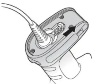
natural_image
Diagram of a medical or electrical device with a cable inserted into a housing, showing internal components and an arrow indicating direction (no text or symbols present)
natural_image
Illustration of a handheld device with a cable inserted into a housing (no text or symbols visible)Technical Assistance
If you need assistance installing or troubleshooting your device, please contact us by using one of the methods below:
Knowledge Base: www.hsmknowledgebase.com
Our Knowledge Base provides thousands of immediate solutions. If the Knowledge Base cannot help, our Technical Support Portal (see below) provides an easy way to report your problem or ask your question.
Technical Support Portal: www.hsmsupportportal.com
The Technical Support Portal not only allows you to report your problem, but it also provides immediate solutions to your technical issues by searching our Knowledge Base. With the Portal, you can submit and track your questions online and send and receive attachments.
Web form: www.hsmcontactsupport.com
You can contact our technical support team directly by filling out our online support form. Enter your contact details and the description of the question/problem.
Telephone: www.honeywellaidc.com/locations
For our latest contact information, please check our website at the link above.
Product Service and Repair
Honeywell International Inc. provides service for all of its products through service centers throughout the world. To obtain warranty or non-warranty service, please visit www.honeywellaidc.com and select Support > Contact Service and Repair to see your region's instructions on how to obtain a Return Material Authorization number (RMA #). You should do this prior to returning the product.
Limited Warranty
Honeywell International Inc. ("HII") warrants its products to be free from defects in materials and workmanship and to conform to HII's published specifications applicable to the products purchased at the time of shipment. This warranty does not cover any HII product which is (i) improperly installed or used; (ii) damaged by accident or negligence, including failure to follow the proper maintenance, service, and cleaning schedule; or (iii) damaged as a result of (A) modification or alteration by the purchaser or other party, (B) excessive voltage or current supplied to or drawn from the interface connections, (C) static electricity or electrostatic discharge, (D) operation under conditions beyond the specified operating parameters, or (E) repair or service of the product by anyone other than HII or its authorized representatives.
This warranty shall extend from the time of shipment for the duration published by HII for the product at the time of purchase ("Warranty Period"). Any defective product must be returned (at purchaser's expense) during the Warranty Period to HII factory or authorized service center for inspection. No product will be accepted by HII without a Return Materials Authorization, which may be obtained by contacting HII. In the event that the product is returned to HII or its authorized service center within the Warranty Period and HII determines to its satisfaction that the product is defective due to defects in materials or workmanship, HII, at its sole option, will either repair or replace the product without charge, except for return shipping to HII.
EXCEPT AS MAY BE OTHERWISE PROVIDED BY APPLICABLE LAW, THE FOREGOING WARRANTY IS IN LIEU OF ALL OTHER COVENANTS OR WARRANTIES, EITHER EXPRESSED OR IMPLIED, ORAL OR WRITTEN, INCLUDING, WITHOUT LIMITATION, ANY IMPLIED WARRANTIES OF MERCHANTABILITY OR FITNESS FOR A PARTICULAR PURPOSE, OR NON-INFRINGEMENT.
HII'S RESPONSIBILITY AND PURCHASER'S EXCLUSIVE REMEDY UNDER THIS WARRANTY IS LIMITED TO THE REPAIR OR REPLACEMENT OF THE DEFECTIVE PRODUCT WITH NEW OR REFURBISHED PARTS. IN NO EVENT SHALL HII BE LIABLE FOR INDIRECT, INCIDENTAL, OR CONSEQUENTIAL DAMAGES, AND, IN NO EVENT, SHALL ANY LIABILITY OF HII ARISING IN CONNECTION WITH ANY PRODUCT SOLD HEREUNDER (WHETHER SUCH LIABILITY ARISES FROM A CLAIM BASED ON CONTRACT, WARRANTY, TORT, OR OTHERWISE) EXCEED THE ACTUAL AMOUNT PAID TO HII FOR THE PRODUCT. THESE LIMITATIONS ON LIABILITY SHALL REMAIN IN FULL FORCE AND EFFECT
EVEN WHEN HII MAY HAVE BEEN ADVISED OF THE POSSIBILITY OF SUCH INJURIES, LOSSES, OR DAMAGES. SOME STATES, PROVINCES, OR COUNTRIES DO NOT ALLOW THE EXCLUSION OR LIMITATIONS OF INCIDENTAL OR CONSEQUENTIAL DAMAGES, SO THE ABOVE LIMITATION OR EXCLUSION MAY NOT APPLY TO YOU.
All provisions of this Limited Warranty are separate and severable, which means that if any provision is held invalid and unenforceable, such determination shall not affect the validity of enforceability of the other provisions hereof. Use of any peripherals not provided by the manufacturer may result in damage not covered by this warranty. This includes but is not limited to: cables, power supplies, cradles, and docking stations. HII extends these warranties only to the first end-users of the products. These warranties are non-transferable.
The duration of the limited warranty for the Granit 1280i scanner is three (3) years.
Symbology Charts
Note: "m" represents the AIM modifier character. Refer to International Technical Specification, Symbology Identifiers, for AIM modifier character details.
Prefix/Suffix entries for specific symbologies override the universal (All Symbologies, 99) entry.
Refer to Data Editing beginning on page 4-1 and Data Formatting beginning on page 5-1 for information about using Code ID and AIM ID.
Linear Symbologies
| AIM Honeywell | ||||
| Symbology ID | Possible modifiers (m) | ID Hex | ||
| All Symbologies 99 | ||||
| Codabar ]Fm 0-1 a 61 | ||||
| Code 11 ]H3 h 68 | ||||
| Code 128 | ]Cm | 0, 1, 2, 4 | j | 6A |
| Code 32 Pharmaceutical (PARAF) | ]X0 | < | 3C | |
| Code 39 (supports Full ASCII mode) | ]Am | 0, 1, 3, 4, 5, 7 | b | 62 |
| TCIF Linked Code 39 (TLC39) | ]L2 | T | 54 | |
| Code 93 and 93i | ]Gm | 0-9, A-Z, a-m | i | 69 |
| EAN | ]Em | 0, 1, 3, 4 | d | 64 |
| EAN-13 (including Bookland EAN) | ]E0 | d 64 | ||
| EAN-13 with Add-On | ]E3 | d 64 | ||
| EAN-13 with Extended Coupon Code | ]E3 | d 64 | ||
| EAN-8 | ]E4 | D | 44 | |
| EAN-8 with Add-On | ]E3 | D | 44 | |
| GS1 | ||||
| GS1 DataBar | ]em | 0 | y | 79 |
| GS1 DataBar Limited | ]em | { | 7B | |
| GS1 DataBar Expanded | ]em | } | 7D | |
| GS1-128 | ]C1 | I | 49 | |
| 2 of 5 | ||||
| China Post (Hong Kong 2 of 5) | ]X0 | Q | 51 | |
| Interleaved 2 of 5 | ]Im | 0, 1, 3 | e | 65 |
| Matrix 2 of 5 | ]X0 | m | 6D | |
| NEC 2 of 5 | ]X0 | Y | 59 | |
| Straight 2 of 5 IATA | ]Rm | 0, 1, 3 | f | 66 |
| Straight 2 of 5 Industrial | ]S0 | f | 66 | |
| MSI | ]Mm | 0, 1 | g | 67 |
| Telepen | ]Bm | t | 74 | |
| UPC | 0, 1, 2, 3, 8, 9, A, B, C | |||
| Symbology ID | Possible modifiers (m) | ID | Hex | |
| UPC-A ]E0 c 63 | ||||
| UPC-A with Add-On ]E3 c 63 | ||||
| UPC-A with Extended Coupon Code ]E3 c 63 | ||||
| UPC-E ]E0 E 45 | ||||
| UPC-E with Add-On ]E3 E 45 | ||||
| UPC-E1 ]X0 E 45 | ||||
| Add Honeywell Code ID 5C80 | ||||
| Add AIM Code ID 5C81 | ||||
| Add Backslash 5C5C | ||||
| Batch mode quantity 5 3 | 5 |
Postal Symbologies
| Symbology ID | AIM Honeywell | |||
| Possible modifiers (m) | ID | Hex | ||
| All Symbologies | 99 | |||
| China Post | ]X0 Q | 51 | ||
ASCII Conversion Chart (Code Page 1252)
In keyboard applications, ASCII Control Characters can be represented in 3 different ways, as shown below. The CTRL+X function is OS and application dependent. The following table lists some commonly used Microsoft functionality. This table applies to U.S. style keyboards. Certain characters may differ depending on your Country Code/PC regional settings.
| Non-printable ASCII control characters | Keyboard Control + ASCII (CTRL+X) Mode | ||||
| Control + X Mode Off (KBDCAS0) | Windows Mode Control + X Mode On (KBDCAS2) | ||||
| DEC | HEX | Char | CTRL + X | CTRL + X function | |
| 0 | 00 | NUL | Reserved | CTRL+ @ | |
| 1 | 01 | SOH | NP Enter | CTRL+ A | Select all |
| 2 | 02 | STX | Caps Lock | CTRL+ B | Bold |
| 3 | 03 | ETX | ALT Make | CTRL+ C | Copy |
| 4 | 04 | EOT | ALT Break | CTRL+ D | Bookmark |
| 5 | 05 | ENQ | CTRL Make | CTRL+ E | Center |
| 6 | 06 | ACK | CTRL Break | CTRL+ F | Find |
| 7 | 07 | BEL | Enter / Ret | CTRL+ G | |
| 8 | 08 | BS | (Apple Make) | CTRL+ H | History |
| 9 | 09 | HT | Tab | CTRL+ I | Italic |
| 10 | 0A | LF | (Apple Break) | CTRL+ J | Justify |
| 11 | 0B | VT | Tab | CTRL+ K | hyperlink |
| 12 | 0C | FF | Delete | CTRL+ L | list, left align |
| 13 | 0D | CR | Enter / Ret | CTRL+ M | |
| 14 0E SO Insert CTRL+ N New | |||||
| 15 0F SI ESC CTRL+ O Open | |||||
| 16 10 DLE F11 CTRL+ P Print | |||||
| 17 11 DC1 | Home | CTRL+ Q Quit | |||
| 18 12 DC2 | PrtScn | CTRL+ R | |||
| 19 13 DC3 | Backspace | CTRL+ S Save | |||
| 20 | 14 | DC4 | Back Tab | CTRL+ T | |
| 21 15 NAK | F12 CTRL+ U | ||||
| 22 16 SYN | F1 | CTRL+ V Paste | |||
| 23 17 ETB F2 | CTRL+ W | ||||
| 24 18 CAN | F3 | CTRL+ X | |||
| 25 19 EM | F4 | CTRL+ Y | |||
| 26 1A SUB | F5 | CTRL+ Z | |||
| 27 1B ESC | F6 | CTRL+ [ | |||
| 28 | 1C | FS | F7 | CTRL+ \ | |
| 29 1D GS F8 | CTRL+ ] | ||||
| 30 1E RS | F9 | CTRL+ ^ | |||
| 31 1F US | F10 CTRL+ - | ||||
| 127 | 7F | NP Enter | |||
Lower ASCII Reference Table
Windows Code page 1252 and lower ASCII use the same characters.
Note:
| Printable Characters | ||||||||
| DEC | HEX | Character | DEC | HEX | Character | DEC | HEX | Character |
| 32 | 20 | 64 | 40 | @ | 96 | 60 | ` | |
| 33 | 21 | ! | 65 | 41 | A | 97 | 61 | a |
| 34 | 22 | " | 66 | 42 | B | 98 | 62 | b |
| 35 | 23 | # | 67 | 43 | C | 99 | 63 | c |
| 36 | 24 | 68 | 44 | D | 100 | 64 | d | |
| 37 | 25 | % | 69 | 45 | E | 101 | 65 | e |
| 38 | 26 | & | 70 | 46 | F | 102 | 66 | f |
| 39 | 27 | ' | 71 | 47 | G | 103 | 67 | g |
| 40 | 28 | ( | 72 | 48 | H | 104 | 68 | h |
| 41 | 29 | ) | 73 | 49 | I | 105 | 69 | i |
| 42 | 2A | * | 74 | 4A | J | 106 | 6A | j |
| 43 | 2B | + | 75 | 4B | K | 107 | 6B | k |
| 44 | 2C | , | 76 | 4C | L | 108 | 6C | l |
| 45 | 2D | - | 77 | 4D | M | 109 | 6D | m |
| 46 | 2E | . | 78 | 4E | N | 110 | 6E | n |
| 47 | 2F | / | 79 | 4F | O | 111 | 6F | o |
| 48 | 30 | 0 | 80 | 50 | P | 112 | 70 | p |
| 49 | 31 | 1 | 81 | 51 | Q | 113 | 71 | q |
| 50 | 32 | 2 | 82 | 52 | R | 114 | 72 | r |
| DEC | HEX | Character | DEC | HEX | Character | DEC | HEX | Character |
| 51 | 33 | 3 | 83 | 53 | S | 115 | 73 | s |
| 52 | 34 | 4 | 84 | 54 | T | 116 | 74 | t |
| 53 | 35 | 5 | 85 | 55 | U | 117 | 75 | u |
| 54 | 36 | 6 | 86 | 56 | V | 118 | 76 | v |
| 55 | 37 | 7 | 87 | 57 | W | 119 | 77 | w |
| 56 | 38 | 8 | 88 | 58 | X | 120 | 78 | x |
| 57 | 39 | 9 | 89 | 59 | Y | 121 | 79 | y |
| 58 | 3A | : | 90 | 5A | Z | 122 | 7A | z |
| 59 | 3B | ; | 91 | 5B | [ | 123 | 7B | |
| 60 | 3C | < | 92 | 5C | \ | 124 | 7C | | |
| 61 | 3D | = | 93 | 5D | ] | 125 | 7D | |
| 62 | 3E | > | 94 | 5E | ^ | 126 | 7E | |
| 63 | 3F | ? | 95 | 5F | _ | 127 | 7F | \bigtriangleup$ |
Extended ASCII Characters
| DEC | HEX | CP 1252 | ASCII | Alternate Extended | PS2 Scan Code |
| 128 | 80 € | Ç | up arrow ↑ | 0x48 | |
| 129 | 81 | ü | down arrow ↓ | 0x50 | |
| 130 | 82, | é | right arrow → | 0x4B | |
| 131 | 83 f | â | left arrow ← | 0x4D | |
| 132 | 84 | „ | ä | Insert | 0x52 |
| 133 | 85 | ... | à | Delete | 0x53 |
| 134 | 86 | † | à | Home | 0x47 |
| 135 | 87 | ‡ | ç | End | 0x4F |
| 136 | 88 | ^ | ê | Page Up | 0x49 |
| 137 | 89 | ‰ | ë | Page Down | 0x51 |
| 138 | 8A | Š | è | Right ALT | 0x38 |
| 139 | 8B | < | ï | Right CTRL | 0x1D |
| 140 | 8C | CE | î | Reserved | n/a |
| 141 | 8D | l | Reserved | n/a | |
| 142 | 8E | Ž | Ä | Numeric Keypad Enter | 0x1C |
| 143 | 8F | Ä | Numeric Keypad / | 0x35 | |
| 144 | 90 | É | F1 | 0x3B | |
| 145 | 91 | ‘ | æ | F2 | 0x3C |
| 146 | 92 | ’ | Æ | F3 | 0x3D |
| 147 | 93 | “ | ô | F4 | 0x3E |
| 148 | 94 | ” | ö | F5 | 0x3F |
| 149 | 95 | • | ò | F6 | 0x40 |
| 150 | 96 | - | ù | F7 | 0x41 |
| 151 | 97 | — | ù | F8 | 0x42 |
| 152 | 98 | ~ | ÿ | F9 | 0x43 |
| 153 | 99 | TM | Ö | F10 | 0x44 |
| 154 | 9A | š | Ü | F11 | 0x57 |
| 155 | 9B | 〉 | ¢ | F12 | 0x58 |
| 156 | 9C | œ | £ | Numeric Keypad + | 0x4E |
| 157 | 9D | ¥ | Numeric Keypad - | 0x4A | |
| 158 | 9E | ž | Pts | Numeric Keypad * | 0x37 |
| 159 | 9F | Ÿ | f | Caps Lock | 0x3A |
| 160 | A0 | á | Num Lock | 0x45 | |
| 161 | A1 | i | í | Left Alt | 0x38 |
| Extended ASCII Characters (Continued) | |||||
| DEC | HEX | CP 1252 | ASCII | Alternate Extended | PS2 Scan Code |
| 162 | A2 | ¢ | ó | Left Ctrl | 0x1D |
| 163 | A3 | £ | ú | Left Shift | 0x2A |
| 164 | A4 | ☐ | ñ | Right Shift | 0x36 |
| 165 | A5 | ¥ | Ñ | Print Screen | n/a |
| 166 A6 † | a | Tab 0x0F | |||
| 167 | A7 | § | ° | Shift Tab | 0x8F |
| 168 | A8 | ~ | ¿ | Enter | 0x1C |
| 169 | A9 | © | ¬ | Esc | 0x01 |
| 170 | AA | a | ¬ | Alt Make | 0x36 |
| 171 | AB | « | 12 | Alt Break | 0xB6 |
| 172 | AC | ¬ | 14 | Control Make | 0x1D |
| 173 | AD | i | Control Break | 0x9D | |
| 174 | AE | ® | « | Alt Sequence with 1 Character | 0x36 |
| 175 | AF | - | » | Ctrl Sequence with 1 Character | 0x1D |
| 176 B0 ° | |||||
| 177 B1 ± | |||||
| 178 B2 2 | |||||
| 179 B3 3 | |||||
| 180 B4 ° | |||||
| 181 B5 μ | |||||
| 182 B6 ¶ | |||||
| 183 B7 ° | |||||
| 184 B8 ° | |||||
| 185 B9 1 | |||||
| 186 | BA | ° | |||
| 187 | BB | » | |||
| 188 | BC | 14 | |||
| 189 | BD | 12 | |||
| 190 | BE | 34 | |||
| 191 | BF | ¿ | |||
| 192 | C0 | À | |||
| 193 | C1 | Á | |||
| 194 | C2 | Â | |||
| 195 | C3 | Â | |||
| 196 | C4 | Ä | |||
| 197 C5 | Â | ||||
| 198 | C6 | Æ | |||
| 199 | C7 | Ç | |||
| 200 | C8 | È | |||
| 201 | C9 | É | |||
| 202 | CA | Ê | |||
| 203 | CB | Ë | |||
| 204 | CC | ì | |||
| 205 | CD | í | |||
| 206 | CE | î | |||
| 207 | CF | î | |||
| 208 | D0 | Đ | |||
| 209 | D1 | Ñ | |||
| 210 | D2 | Ò | |||
| 211 | D3 | Ó | |||
| 212 | D4 | Ô | |||
| 213 | D5 | Ô | |||
| 214 D6 O | |||||
| 215 D7 x | |||||
| 216 D8 O = | |||||
| 217 D9 U | |||||
| 218 DA U | |||||
| 219 DB U | |||||
| 220 DC U | |||||
| 221 DD Y | |||||
| 222 DE P | |||||
| 223 DF B | |||||
| 224 E0 a α | |||||
| 225 E1 a | β | ||||
| 226 E2 a Γ | |||||
| 227 E3 a π | |||||
| 228 E4 a Σ | |||||
| 229 E5 a σ | |||||
| 230 E6 ae | μ | ||||
| 231 E7 c T | |||||
| 232 E8 e Φ | |||||
| 233 E9 e Θ | |||||
| 234 EA e Ω | |||||
| 235 EB e δ | |||||
| 236 EC I ∞ | |||||
| 237 ED i φ | |||||
| 238 EE i ε | |||||
| 239 EF i n | |||||
| 240 F0 δ ≡ | |||||
| 241 F1 n | ± | ||||
| 242 F2 o ≥ | |||||
| 243 F3 o ≤ | |||||
| 244 F4 δ [ | |||||
| 245 F5 δ ] | |||||
| 246 F6 δ | ÷ | ||||
| 247 F7 ÷ ≈ | |||||
| 248 F8 ø | ° | ||||
| 249 F9 ü | |||||
| 250 FA ü | . | ||||
| 251 FB ü √ | |||||
| 252 FC ü n | |||||
| 253 FD y | 2 | ||||
| 254 FE p ■ | |||||
| 255 FF y | |||||
ISO 2022/ISO 646 Character Replacements
Code pages define the mapping of character codes to characters. If the data received does not display with the proper characters, it may be because the bar code being scanned was created using a code page that is different from the one the host program is expecting. If this is the case, select the code page with which the bar codes were created. The data characters should then appear properly.
| Code Page Selection Method/Country | Standard | Keyboard Country | Honeywell Code Page Option |
| United States(standard ASCII) | ISO/IEC 646-IRV n/a 1 | ||
| Automatic National Character Replacement | ISO/IEC 2022 n/a 2 (default) | ||
| Binary Code page n/a n/a 3 | |||
| Default “Automatic National Character replacement” will select the below Honeywell Code Page options for Code128, Code 39 and Code 93. | |||
| United States ISO/IEC 646-06 0 1 | |||
| Canada ISO /IEC 646-121 54 95 | |||
| Canada ISO /IEC 646-122 18 96 | |||
| Japan ISO/IEC 646-14 28 98 | |||
| China | ISO/IEC 646-57 92 99 | ||
| Great Britain (UK) | ISO /IEC 646-04 7 87 | ||
| France | ISO /IEC 646-69 3 83 | ||
| Germany | ISO/IEC646-21 4 84 | ||
| Switzerland | ISO /IEC 646-CH | 6 86 | |
| Sweden / Finland (extended Annex C) | ISO/IEC 646-11 2 82 | ||
| Ireland | ISO /IEC 646-207 73 97 | ||
| Denmark | ISO/IEC 646-08 8 88 | ||
| Norway | ISO/IEC 646-60 9 94 | ||
| Italy | ISO/IEC 646-15 5 85 | ||
| Portugal | ISO/IEC 646-16 13 92 | ||
| Spain | ISO/IEC 646-17 10 90 | ||
| Spain | ISO/IEC 646-85 51 91 | ||
| Dec | 3536649192939496123124125126 | |||||||||||||
| Hex | 2324405B5C5D5E607B7C7D7E | |||||||||||||
| US | 0 | 1 | # | @ | [ | \ | ] | ^ | ` | | | ||||
| CA | 54 | 95 | #aáçêiõé | ù | è | û | ||||||||
| CA | 18 | 96 | #aáçêÉõé | ù | è | û | ||||||||
| JP | 28 | 98 | # | @[¥]^{} | } | - | ||||||||
| CN | 92 | 99 | # | ¥ | @ | [ | \ | ] | ^ | ` | { | | | } | - |
| GB | 787 | £ | @ | [ | \ | ] | ^ | ` | | | |||||
| FR | 383 | £à° | ç§^μé | ù | è | .. | ||||||||
| DE | 4 | 84 | # | § | Ä | Ö | Ü | ^ | ` | ä | ö | ü | ß | |
| CH | 686 | ù | à | é | ç | ê | î | ô | ä | ö | ü | û | ||
| SE/FI282 | # | ¤ | É | Ä | Ö | Å | Ü | é | ä | ö | å | ü | ||
| DK | 8 | 88 | # | @ | Æ | ∅ | Å | ^ | ` | æ | ø | å | ||
| NO | 994 | # | @ | Æ | ∅ | Å | ^ | ` | æ | ø | å | .. | ||
| IE | 73 | 97 | £Ó | É | ÍÚÁóéíú | á | ||||||||
| IT | 585 | £ | § | ° | ç | é | ^ | ù | à | ò | è | ì | ||
| PT13 | 92 | # | § | Ä | Ç | Ö | ^ | ` | ä | ç | õ | ° | ||
| ES10 | 90 | # | § | i | Ñ | ¿ | ^ | ` | ° | ñ | ç | ~ | ||
| ES51 | 91 | # | $ | · | i | Ñ | Ç | ¿ | ` | ` | ñ | ç | .. | |
| COUNTRY | Country Keyboard | Honeywell CodePage | ISO / IEC 646 National Character Replacements | |||||||||||
Unicode Key Maps

104 Key U.S. Style Keyboard

105 Key European Style Keyboard
Sample Symbols
UPC-A
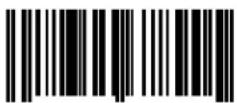
0 123456 7890
Interleaved 2 of 5

1234567890
EAN-13

9 780330 290951
Code 128

Code 128
Code 39

BC321
Codabar

A13579B
Code 93

123456-9\$
Programming Chart




Programming Chart


Note: If you make an error while scanning the letters or digits (before scanning Save), scan Discard, scan the correct letters or digits, and Save again.
Honeywell Scanning & Mobility
9680 Old Bailes Road
Fort Mill, SC 29707
www.honeywellaidc.com




- Disclaimer
- Product Agency Compliance - Granit 1280i
- USA
- FCC Part 15 Subpart B Class B
- TÜV-R Statement
- Canada
- Industry Canada ICES-003
- Europe
- Honeywell Scanning & Mobility Product Environmental Information
- Australia/NZ
- C-Tick Statement
- Mexico
- Japan
- Taiwan
- International
- CB Scheme
- Laser Safety Statement
- Patents
- Solids and Water Protection
- Warning
- Required Safety Labels
- Table of Contents
- Chapter 1 - Getting Started
- Chapter 2 - Programming the Interface
- Chapter 3 - Input/Output Settings
- Chapter 4 - Data Editing
- Chapter 5 - Data Formatting
- Chapter 6 - Symbologies
- Chapter 7 - Utilities
- Chapter 8 - Serial Programming Commands
- Chapter 9 - Product Specifications
- Chapter 10 - Maintenance
- Chapter 11 - Customer Support
- Appendix A - Reference Charts
- Getting Started
- About This Manual
- Unpacking Your Device
- Connecting the Device
- Reading Techniques
- Cyber Security Settings
- Setting Custom Defaults
- Resetting the Custom Defaults
- Programming the Interface
- Introduction
- Programming the Interface - Plug and Play
- RS232 Serial Port
- OPOS Mode
- Verifone® Ruby Terminal Default Settings
- Symbology Prefix
- Gilbarco ® Terminal Default Settings
- Honeywell Bioptic Aux Port Configuration
- Datalogic™ Magellan® Aux Port Configuration
- NCR Bioptic Aux Port Configuration
- Wincor Nixdorf Terminal Default Settings
- Wincor Nixdorf Beetle™ Terminal Default Settings
- RS232 Modifiers
- RS232 Baud Rate
- RS232 Word Length: Data Bits, Stop Bits, and Parity
- RS232 Handshaking
- RS232 Timeout
- XON/XOFF
- ACK/NAK
- Communication Timeout
- Timeout Retries
- Communication Timeout Beeper
- NAK Retries
- Support BEL/CAN in ACK/NAK
- RS232 Defaults
- NCR Modifiers
- NCR ACK/NAK
- Block Check Character
- NCR Prefix
- NCR Suffix
- NCR Prefix/Suffix
- NCR NOF (Not-on-File) Error
- Scanner to Bioptic Communication
- Scanner-Bioptic Packet Mode
- Power Save Mode
- Power Save Mode Timeout
- Power Up Beeper
- Beep on BEL Character
- Good Read and Error Indicators
- Beeper – Good Read
- Beeper Volume – Good Read
- Beeper Pitch – Good Read
- Beeper - Transmit Order
- Vibrate – Good Read
- Vibrate Duration
- Beeper Pitch – Error
- Beeper Duration – Good Read
- Number of Beeps – Good Read
- Number of Beeps - Error
- Beeper Volume Max
- Laser Aimer
- Laser Aimer - Scanning Pattern
- Laser Aimer - Scanning Duration
- Laser Aimer - Good Read Pattern
- Laser Aimer - Good Read Duration
- Aimer Delay
- User-Specified Aimer Delay
- LED Indicators
- LED Settings
- Good Read Delay
- User-Specified Good Read Delay
- Out-Of-Stand Settings
- Out-of-Stand Defaults
- Presentation Mode
- Manual Activation Mode
- End Manual Activation After Good Read
- Manual Activation Laser Timeout - Trigger Settings
- Reread Delay
- User-Specified Reread Delay
- CodeGate®
- Character Activation Mode
- Activation Character
- End Character Activation After Good Read
- Character Activation Timeout
- Character Deactivation Mode
- Deactivation Character
- Centering
- Blinky Mode
- Laser Scan Angle
- Decode Security
- Continuous Scan Mode
- Output Sequence Overview
- Output Sequence Editor
- To Add an Output Sequence
- Character Match Sequences
- End Output Sequence Editor
- Other Programming Selections
- - Discard
- Output Sequence Example
- Sequence Timeout
- Sequence Match Beeper
- Partial Sequence
- Require Output Sequence
- No Read
- Prefix/Suffix Overview
- Points to Keep In Mind
- To Add a Prefix or Suffix:
- Example: Add a Tab Suffix to All Symbologies
- To Clear One or All Prefixes or Suffixes
- To Add a Carriage Return Suffix to All Symbologies
- Prefix Selections
- Suffix Selections
- Function Code Transmit
- Communication Check Character
- Intercharacter, Interfunction, and Intermessage Delays
- Intercharacter Delay
- User Specified Intercharacter Delay
- Interfunction Delay
- Intermessage Delay
- Data Format Editor Introduction
- Add a Data Format
- Step 5. Length
- Step 6. Editor Commands
- Clear One Data Format
- Clear all Data Formats
- Terminal ID Table
- Data Format Editor Commands
- Send Commands
- Send all characters
- Send a number of characters
- F2 Example: Send a number of characters
- F2 and F1 Example: Split characters into 2 lines
- Send all characters up to a particular character
- Send all characters up to a string
- Send all but the last characters
- Insert a character multiple times
- Insert a string
- Insert symbology name
- Insert bar code length
- Insert key strokes
- Move Commands
- Move the cursor forward a number of characters
- Move the cursor backward a number of characters
- Move the cursor to the beginning
- Move the cursor to the end
- Search Commands
- Search forward for a character
- Search backward for a character
- Search forward for a string
- Search backward for a string
- Search forward for a non-matching character
- Search backward for a non-matching character
- Miscellaneous Commands
- Suppress characters
- Stop suppressing characters
- Replace characters
- Stop replacing characters
- Compare characters
- Compare string
- Check for a number
- EC Example: Only output the data if the bar code begins with a number
- Check for non-numeric character
- ED Example: Only output the data if the bar code begins with a letter
- Insert a delay
- Discard Data
- Data Formatter
- Data Formatter On, Not Required, Keep Prefix/Suffix
- Data Formatter On, Not Required, Drop Prefix/Suffix
- Data Format Required, Keep Prefix/Suffix
- Data Format Required, Drop Prefix/Suffix
- Data Format Non-Match Error Tone
- Primary/Alternate Data Formats
- Single Scan Data Format Change
- All Symbologies
- Message Length Description
- Codabar
- Codabar Start/Stop Characters
- Codabar Check Character
- Codabar Concatenation
- Concatenation Timeout
- Codabar Redundancy
- Codabar Message Length
- Code 39
- Code 39 Start/Stop Characters
- Code 39 Check Character
- Code 39 Redundancy
- Code 39 Message Length
- Code 39 Append
- Code 32 Pharmaceutical (PARAF)
- Full ASCII
- Code 39 Code Page
- Interleaved 2 of 5
- Interleaved 2 of 5 On/Off
- NULL Characters
- Check Digit
- Interleaved 2 of 5 Redundancy
- Interleaved 2 of 5 Message Length
- Matrix 2 of 5
- Matrix 2 of 5 Check Character
- Matrix 2 of 5 Redundancy
- Matrix 2 of 5 Message Length
- NEC 2 of 5
- NEC 2 of 5 Redundancy
- NEC 2 of 5 Message Length
- Code 93
- Code 93 On/Off
- Code 93 Redundancy
- Code 93 Message Length
- Code 93 Append
- Code 93 Code Page
- Straight 2 of 5 Industrial (three-bar start/stop)
- Straight 2 of 5 Industrial On/Off
- Straight 2 of 5 Industrial Redundancy
- Straight 2 of 5 Industrial Message Length
- Straight 2 of 5 IATA (two-bar start/stop)
- Straight 2 of 5 IATA Redundancy
- Straight 2 of 5 IATA Message Length
- Code 11
- Check Digits Required
- Code 11 Redundancy
- Code 11 Message Length
- Code 128
- Group Separator Output
- Code 128 Redundancy
- Code 128 Message Length
- Code 128 Append
- ISBT 128 Concatenation
- ISBT 128 Predefined Concatenation Sequences
- ISBT 128 Predefined Concatenation Sequences On/Off
- ISBT 128 User-Defined Concatenation Sequences
- ISBT 128 User-Defined Concatenation Sequences On/Off
- Content Verification
- Transmit Identifiers
- Flag Digit Conversion
- GS1-128
- GS1-128 Application Identifier Parsing
- GS1-128 Redundancy
- GS1-128 Message Length
- Telepen
- Telepen On/Off
- Telepen Output
- Telepen Redundancy
- Telepen Message Length
- UPC-A
- UPC-A On/Off
- UPC-A Check Digit
- UPC-A Number System
- UPC-A Addenda
- UPC-A Addenda Required
- UPC-A Addenda Separator
- Addenda Timeout
- UPC-A Redundancy
- UPC-A/EAN-13
- with Extended Coupon Code
- UPC-A/Code 128 Coupon Code Output
- UPC-A Number System 4 Addenda Required
- UPC-A Number System 5 Addenda Required
- Coupon GS1 DataBar Output
- UPC-E0
- UPC-E0 On/Off
- UPC-E0 Expand
- UPC-E0 Number System
- UPC-E0 Number System and Check Digit
- UPC-E0 Addenda Required
- UPC-E0 Addenda Separator
- UPC-E0 Check Digit
- UPC-E0 Leading Zero
- UPC-E0 Addenda
- UPC-E0 Redundancy
- EAN/JAN-13
- Convert UPC-A to EAN-13
- EAN/JAN-13 Check Digit
- EAN/JAN-13 Addenda
- EAN/JAN-13 Addenda Required
- EAN-13 Beginning with 2 Addenda Required
- EAN-13 Beginning with 290 Addenda Required
- EAN-13 Beginning with 378/379 Addenda Required
- EAN-13 Beginning with 414/419 Addenda Required
- EAN-13 Beginning with 434/439 Addenda Required
- EAN-13 Beginning with 977 Addenda Required
- EAN-13 Beginning with 978 Addenda Required
- EAN-13 Beginning with 979 Addenda Required
- EAN/JAN-13 Addenda Separator
- EAN/JAN-13 Redundancy
- ISBN Translate
- Convert ISBN to 13-Digit
- ISBN Reformat
- ISSN Translate
- ISSN Reformat
- EAN/JAN-8
- EAN/JAN-8 Check Digit
- EAN/JAN-8 Addenda
- EAN/JAN-8 Addenda Required
- EAN/JAN-8 Addenda Separator
- EAN/JAN-8 Redundancy
- MSI
- MSI On/Off
- MSI Check Character
- MSI Redundancy
- MSI Message Length
- Plessey Code
- Plessey Check Character
- Plessey Redundancy
- Plessey Message Length
- GS1 DataBar Omnidirectional
- GS1 DataBar Omnidirectional On/Off
- GS1 DataBar Omnidirectional Redundancy
- GS1 DataBar Limited
- GS1 DataBar Limited Redundancy
- GS1 DataBar Expanded
- GS1 DataBar Expanded On/Off
- GS1 DataBar Expanded Redundancy
- GS1 DataBar Expanded Message Length
- Trioptic Code
- GS1 Emulation
- China Post (Hong Kong 2 of 5)
- China Post (Hong Kong 2 of 5) On/Off
- China Post (Hong Kong 2 of 5) Redundancy
- China Post (Hong Kong 2 of 5) Message Length
- To Add a Test Code I.D. Prefix to All Symbologies
- Show Software Revision
- Show Data Format
- Test Menu
- TotalFreedom
- Application Plug-Ins (Apps)
- EZConfig-Scanning Introduction
- EZConfig-Scanning Operations
- Scan Data
- Configure
- Installing EZConfig-Scanning from the Web
- Resetting the Factory Defaults
- Serial Programming Commands
- Conventions
- Menu Command Syntax
- Query Commands
- :Name: Field Usage (Optional)
- Tag Field Usage
- SubTag Field Usage
- Data Field Usage
- Concatenation of Multiple Commands
- Responses
- Examples of Query Commands
- Serial Trigger Commands
- Read Time-Out
- Depth of Field Charts
- Standard Connector Pinouts
- Serial Output
- Repairs
- Maintenance
- Cleaning the Scanner
- Caution:
- Cleaning the Window
- Inspecting Cords and Connectors
- Replacing Cables
- Replacing an Interface Cable
- Troubleshooting
- Is the power on? Is the aimer on?
- Is the scanner having trouble reading your symbols?
- Is the bar code displayed but not entered?
- Does the scanner read the bar code incorrectly?
- The scanner won't read your bar code at all.
- Technical Assistance
- Product Service and Repair
- Limited Warranty
- Symbology Charts
- ASCII Conversion Chart (Code Page 1252)
- Lower ASCII Reference Table
- ISO 2022/ISO 646 Character Replacements
- Unicode Key Maps
- Sample Symbols
Brand : HONEYWELL
Model : Granit 1280i
Category : Barcode Reader