USER MANUAL CCD Barcode Scanner MANHATTAN
V3.8 a
Notice
The manufacturer shall not be liable for technical or editorial errors or omissions contained herein; nor for incidental or consequential damages in connection with the furnishing, performance or use of use the publication.
Contents
Chapter 1 Description
1.1 Notice 3
1.2 Introduction 4
1.3 Codes Read 4
1.4 Installation 4
1.5 Pin Assignment 6
Chapter 2 Configuration - General
2.1 Flow Chart 8
2.2 Loop of Programming 9
2.3 Factory Default Settings 9
2.4 Main Page of Configuration.... 10
Chapter 3 Interface and Reading Mode Selection
3.1 Interface Selection 11
3.2 Memory Function 11
3.3 Reading Mode Selection 12
Chapter 4 Communication Parameters
4.1 RS232 Mode Parameters 13
4.2 Keyboard Wedge Mode Parameters..... 15
4.3 Output Characters Parameters ...... 17
4.4 Wand Emulation Mode Parameters..... 19
Chapter 5 Bar Codes & Others
5.1 Symbologies Selection 20
5.2 UPC/EAN/JAN Parameters 24
5.3 Code 39 Parameters 26
5.4 Code 128 Parameters 28
5.5 Interleave 25 Parameters .... 30
5.6 Industrial 25 Parameters ...... 32
5.7 Matrix 25 Parameters 34
5.8 CODABAR/NW7 Parameters 36
5.9 Code 93 Parameters ...... 38
5.10 Code 11 Parameters 40
5.11 MSI/PLESSEY Code Parameters ..... 42
5.12 Code 2 of 6 Parameters ..... 44
5.13 LCD 25 Parameters 46
5.14 Telepen Parameters 48
5.15 GS1 DataBar (RSS Code) 50
Chapter 6 Miscellaneous Parameters
6.1 Language Selection 52
6.2 Bar Code ID 54
6.3 Reading Level 57
6.4 Accuracy 57
6.5 Buzzer Beep Tone 57
6.6 LED Control 57
6.7 Same Code Delay Reading Interval ..... 58
6.8 Notebook Function 58
6.9 Reverse Output Characters 59
6.10 Set Up Deletion 59
6.11 Set Up Insertion 62
6.12 Set Up IR Sensor 65
Appendix
A. Decimal Value Tables 67
B. ASCII Tables 68
C. Function Key Tables 72
Chapter 1 Description
1.1 General
Thank you for purchasing this barcode scanner with an advanced and versatile decoder. The decoder works with variety of barcode types, reading devices, and computer interfaces. It discriminates over twenty different symbologies automatically.
This menu provides an easy way to configure the decoding options and interface selections by scanning bar codes listed in the menu.
FCC Approval

This device had been tested in accordance with the procedures and in compliance with Part 15 Subpart B of FCC Rules. And keeps all requirements according ANSI C63.4 & FCC Part 15 B Regulation and CISPR22 Class B.
CE Standards

The CE mark as shown here indicates this product had been tested in accordance with the procedures given in European Council Directive 2004/108/EC and confirmed to comply with the Europe Standard EN55022:2006:Class B, EN 55024:1998+A1:2001+A2:2003, IEC61000-3-2:2006, IEC61000-3-3:1995+A1:2005, IEC61000-4-2:2001, IEC61000-4-3:2006, IEC61000-4-4:2004, IEC61000-4-5:2006, IEC61000-4-6:2001, IEC61000-4-8:2001, IEC61000-4-11:2004.
LEGISLATION AND WEEE SYMBOL
This marking shown on the product or its literature, indicates that it should not be disposed with other households wastes at the end of its working life. To prevent possible harm to the environment or human healthy from uncontrolled waste disposal, please separate this from other types of wastes and recycle it responsibly to promote the sustainable reuse of material resources.
Household users should contact either the retailer where they purchased this product, or their local government office, for details of wher and how they can take this item fore environm entally safe recycling. Business users should contact their supplier and check the terms and conditions of the purchase
1.2 Introduction
The Decoder is an advanced and versatile decoding facility for barcoding systems. It works with variety of bar code types, reading devices, and computer interfaces. It discriminates about twenty different symbologies automatically.
This menu provide an easy way to config the decoding options and interface selections by scanning bar codes listed in the menu.
1.3 Codes Read
. Codes Read
ALL UPC/EAN/JAN, Code 39, Code 39 Full ASCII, Code 128, Interleave 25, Industrial 25, Matrix 25, CODABAR/NW7, Code 11, MSI/PLESSEY, Code 93, China Postage, Code32/Italian Pharmacy Others available upon request.
1.4 Installation
Unpacking –
Remove the scanner from its packing and check it for damage. If the scanner was defected in transit, please contact your vendor immediately. Be sure that you keep the packing with all accessories contains in the package for your returning of service.
Connecting the scanner –
Keyboard wedge/RS-232C/USB:
Connect the 10-pins RS-45 male connector into the bottom of the scanner and you will hear a "click" when the connection is made.
Power supply for RS-232C scanner—
There are 3 ways to supplying the power, use external +5V power supply, use optional power cable (KBDC) which taking the power from KB wedge or if the host supports +5V power from pin 9.
Installing the scanner to the Host System –
- Turn off the host system.
- Connect the power if needed.
- Connect to the proper port on the host system.
- Turn on the host system.
Switching cable –
Before removing the cable from the scanner, it is recommended that the power on the host system is off and the power supply has been disconnected from unit.
- Find the small "Pin-hole" on the bottom of the unit.
- Use a bended regular paperclip and insert the tip into the hole.
- You will head a "click", then gentle on the strain-relief of the cable and it will slide out of the scanner.

natural_image
Line drawings of two different types of hairless sensors, one with a threaded tip and the other with a plug inserted (no text or symbols on the devices themselves)

natural_image
Technical line drawing of a mechanical component with an inset close-up showing internal threading (no text or symbols)
SD Series
1.5 Pin Assignment
DB 9 Male
Pin No. Wand / CCD / Slot Reader Laser Scanner
1 N.C. S.O.S.
2 DATA DATA
3 N.C. N.C.
4 N.C. N.C.
5 N.C. TRIGGER
6 N.C. P. E.
7 GND GND
8 SHIELD SHIELD
9 +5V +5V

B> Output Port
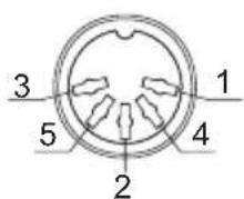
1. PC Keyboard Output
DIN 5 MALE DIN 5 FEMALE
| Pin No. | Function | Pin No. | Function |
| 1 | HOST CLK | 1 | KB CLK |
| 2 | HOSTDATA | 2 | KBDATA |
| 4 | GND | 4 | GND |
| 5 | Vcc(+5V) | 5 | Vcc(+5V) |

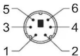
MiniDIN 6 MALE
| Pin No. | Function | Pin No. | Function |
| 1 | HOSTDATA | 1 | KBDATA |
| 3 | GND | 3 | GND |
| 4 | Vcc | 4 | Vcc |
| 5 | HOST CLK | 5 | KB CLK |

2. RS-232 Output
DB 9 Female
Pin No. Function
2 TXD
3 RXD
5 GND
7 CTS
8 RTS
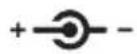
Power Lead Vcc (+5V)

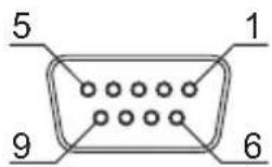
3. WAND Emulation Output
DB 9 Female
Pin No. Function
2 DATA
7 GND
9 Vcc (+5V)
4. ADB Interface
MiniDIN 4 MALE MiniDIN 4 FEMALE
Pin No. Function
Pin No. Function
1 ADB 1 ADB
3 Vcc 3 Vcc
4 GND 4 GND


5. NEC 9801 Interface
MiniDIN 8 MALE MiniDIN 8 FEMALE
Pin No. Function
Pin No. Function
1 RST 1 RST
2 GND 3 GND
3 HOST RDY
4 KB RDY
4 HOST DATA
5 KB DATA
Chapter 2 Configuration - General
2.1 Flow Chart

flowchart
graph TD
    A["Start Configuration"] --> B["Interface Selection\nInput Port Selection\nCommunication\nParameters\nBar Codes Parameters\nMSR PParameters\nMisc. Parameters\netc."]
    B --> C["Abort Configuration"]
    B --> D["End Configuration"]
    C --> E["Save Parameters"]
    D --> E
    F["Recall Parameter"] --> D
    G["Set All Defaults"] --> E
2.2 Loop of Programming
The philosophy of programming parameters has been shown on the flow chart of 2.1. Basically user should
- Scan Start of Configuration.
- Scan all necessary labels for parameters that meet applications.
- Scan End of Configuration to end the programming.
- To permanently save the settings you programmed, just scan label for Save Parameters.
- To go back to the Default Settings, just scan label for Set All Defaults.
2.3 Factory Default Settings
The factory default settings are shown with <> and bold in the following sections. You can make your own settings by following the procedures in this manual. If you want to save the settings permanently, you should scan the label of "Save Parameters" in chapter 2.4, otherwise the settings will not be saved after the decoder power is off, and all settings will go back to previous settings.
By scanning "Set All Default" label, the settings will go back to the factory default settings.
2.4 Main Page of Configuration

bar
| Category | Value (%) |
| :--- | :--- |
| Save Parameters | +0 |
| Recall Stored Parameters | +1 |
| Set All Defaults | +2 |
| Start Configuration | +3 |
| End Configuration | +4 |
| Abort Configuration | +6 |
| Version Information | +5 |
Save Parameters -
The parameter settings will be saved permanently.
Recall Stored Parameters -
Replace the current parameters by the parameters you saved last time.
Set All Defaults -
Set all the parameters to the factory default settings.
Abort Configuration -
Terminate current programming status.
Display the decoder version information and date code.
Chapter 3 Interface and Reading Mode Selection
3.1 Interface Selection

RS232 Mode

WAND Emulation

USB Mode

3.2 Memory Function

Disable

3.3 Reading Mode Selection

Trigger ON/OFF

Continuous/Trigger OFF
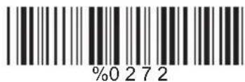
Testing
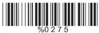
Continuous/Auto Power On

Flash
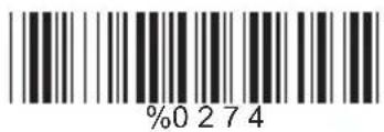
Flash/Auto Power On
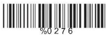
Reserved1
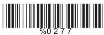
Reserved 2 ( Auto Sense Option)

Reserved3

Reserved4

Reserved5
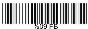
Ch.4 Communication Parameters
4.1 RS232 Communication Parameters
A> Set Up BAUD Rate

B> Set Up Data Bits
7 Data Bits

<8 Data Bits>

C> Set Up Stop Bits
<1 Bit>
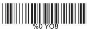
2 Bits
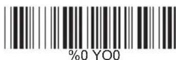
D> Set Up Parity
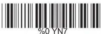
Odd

Space

Even
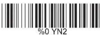
Mark
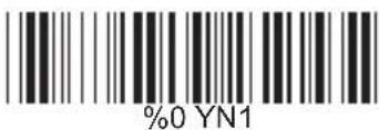
E> Handshaking
RTS/CTS Enable

ACK/NAK Enable

XON/XOFF Enable


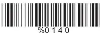

4.2 Keyboard Wedge Mode Parameters A> Terminal Type

B> Upper/Lower Case
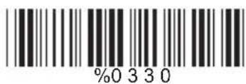
Upper Case
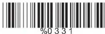
Lower Case

C> Capslock Detection
Enable
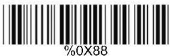

D> Send Character by ALT Method
Enable


E>Select Numerical Pad
ON
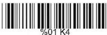
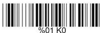
4.3 Output Characters Parameters
A> Select Terminator

B> Time-out Between Characters
<0 ms>

5 ms

10 ms

25 ms

50 ms
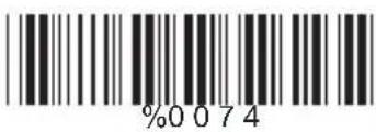
100 ms

200 ms

300 ms

4.4 Wand Emulation Mode Parameters
A> TTL Level Representation
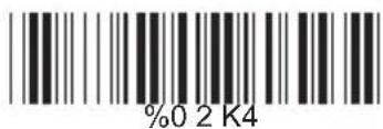
Bar Equals Low

B> Scan Speed Selection

Slow
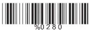
C> Output Format Selection