
Coronis 5MP - Monitor Barco - Free user manual and instructions
Find the device manual for free Coronis 5MP Barco in PDF.


| Product Type | Medical Diagnostic Monitor |
| Resolution | 5 Megapixels (2560 x 2048) |
| Screen Size | 21.3 inches (diagonal) |
| Pixel Pitch | 0.165 mm |
| Brightness | 1000 cd/m² (typical) |
| Contrast Ratio | 1000:1 (typical) |
| Viewing Angle | 170° horizontal / 170° vertical |
| Calibration | DICOM Part 14 compliant, built-in front sensor |
| Inputs | DVI-D, DisplayPort |
| Power Consumption | ≤ 35 W (typical) |
| Weight | Approximately 8.5 kg (18.7 lbs) |
| Dimensions (W x H x D) | 476 x 464 x 93 mm (18.7 x 18.3 x 3.7 in) |
| Operating Temperature | 0°C to 40°C (32°F to 104°F) |
| Mounting | VESA 100 x 100 mm |
| Warranty | 3 years (standard) |
| Cleaning | Use a soft, lint-free cloth with mild detergent |
| Power Supply | AC 100-240 V, 50/60 Hz |
| Backlight | LED, rated for 50,000 hours |
| Color Support | 10-bit (1.07 billion colors) |
Frequently Asked Questions - Coronis 5MP Barco
User questions about Coronis 5MP Barco
0 question about this device. Answer the ones you know or ask your own.
Ask a new question about this device
Download the instructions for your Monitor in PDF format for free! Find your manual Coronis 5MP - Barco and take your electronic device back in hand. On this page are published all the documents necessary for the use of your device. Coronis 5MP by Barco.
USER MANUAL Coronis 5MP Barco
natural_image
Exterior view of a black CRT monitor with 'BIPCO' branding, mounted on a stand against a plain background (no text or symbols on the device itself)UserGuide
MDCG-5121
Barco nv
President Kennedypark 35, 8500 Kortrijk, Belgium
Phone: +32 56.23.32.11
Fax: +32 56.26.22.62
Support: www.barco.com/esupport
Visit us at the web: www.barco.com
1.WELCOME!
1.1 About the product
Overview
The high-grade Coronis 5MP display system offers unsurpassed film-like images with ultra-high resolution, luminance and contrast. The 21.3"LCD provides unequaled image equality without pixelization, a wide viewing angle and perfect geometry.
Buildingonproventechnology, Coronis5MP provides ultimate precision and performance while maintaining the highest brightness and contrast. The advanced 10-bit architecture ensures accurate image representations with 1024 simultaneous shades of grayout of a palette of 4096.

CAUTION: Read all the important safety information before installing and operating your Coronis5MP.Pleaserefertothededicatedchapterinthisuserguid e.
1.2 What's in the box
Overview
YourCoronis5MPcomeswith:
- thedisplay
• asystemtiltandswivelfoot
• thisCoronis5MPuserguide - asystemCD
- aDisplayPortable
- a DVI cable
- an USB cable
- an AC power cord
- anexternalpowersupply
If you ordered a Barcodisplaycontroller, it's also in the box together with its accessories. Adedicated user guide is available on the system CD.

Keepyouroriginalpackaging.Itisdesignedforthisdisplayandistheideal protection duringtransportandstorage.
2.PARTS,CONTROLSAND CONNECTORS
2.1 Displayfrontview
Overview
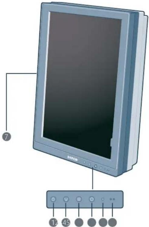
Image2-1 Frontview
1 I-Luminate/Leftkey
3 Menukey
5 Ambientlight sensor
7 Side downstream USB 2 & 3
② Rightkey
4 Poweron/off key
6 Power LEDs
2.2 Displayrearview
Connectorcompartmentoverclosed
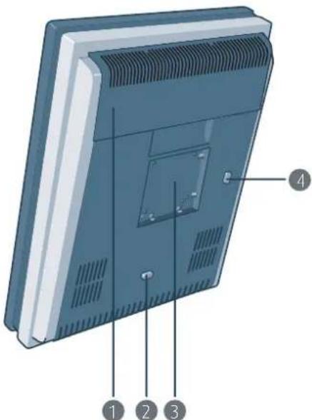
Image2-2 Rearviewcoverclosed
1 Connectorcompartmentcover
3 Mountinganchor
2 Displayreleasebuttonforportraitposition
4 Displayreleasebuttonforlandscapeposition
Connectorcompartmentcoveropen
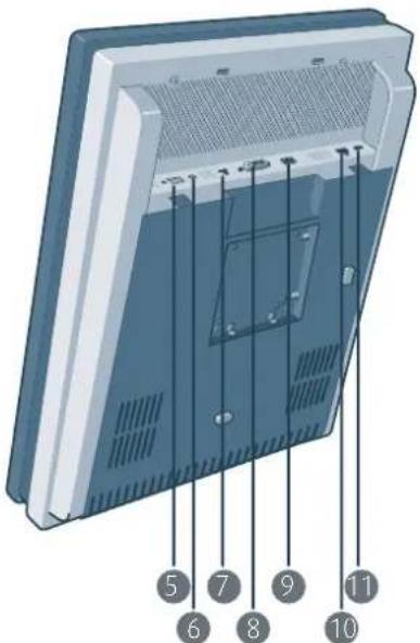
Image2-3 Rearviewcoveropen
5 24Vdcpowerinput
7 DisplayPortvideoinput
⑨ Ethernetconnection(seenotebelow)
11 USBdownstream1
6 +5Vdc,0.5Apoweroutput
8 DVIvideoinput
10 USBupstream

TheEthernetconnectionisusedformaintenancepurposesandisnotsupportedfor userapplication.
2.3Foot
Singlefoot
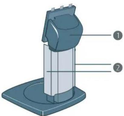
Image2-4
1 Tilt&Swivelneckcover
② Cableductcovers
Dualfoot
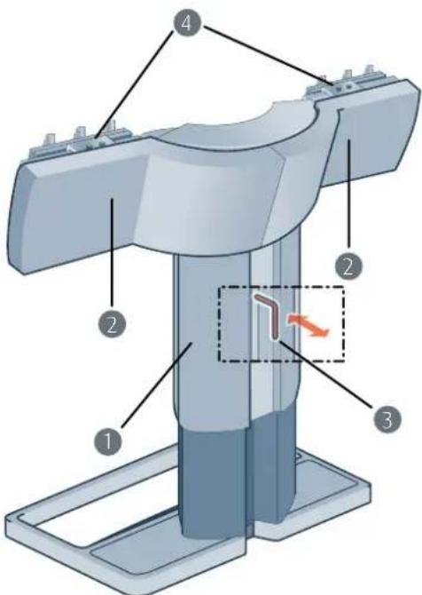
Image2-5 Dualtiltandswivelfoot
1 Cablecover
2 Left&rightarmcover
4 Displaypositioningsliders
3.DISPLAYINSTALLATION

Prior to installing your Coronis 5MP and connecting all necessary cables, make sure to haveasuitabledisplaycontrollerphysicallyinstalledinyourcomputer.Ifyouareusing aBarcodisplaycontroller,pleaseconsulttheuserguidedeliveredwithittodothis.
3.1Mountingthedisplays

WARNING: Do not change the display orientation by turning the panel when it is mounted on its stand.
To change from landscape to portrait or the other way around, remove the panel from itsstandandusetheappropriatemountinghooksasdescribedabove.
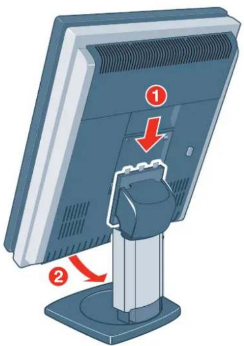
Usingthesingletilt&swivelfoot(portraitorientation)
- Unpack the single tilt & swivel foot and place it on a solid surface.
- Unpack the display.
natural_image
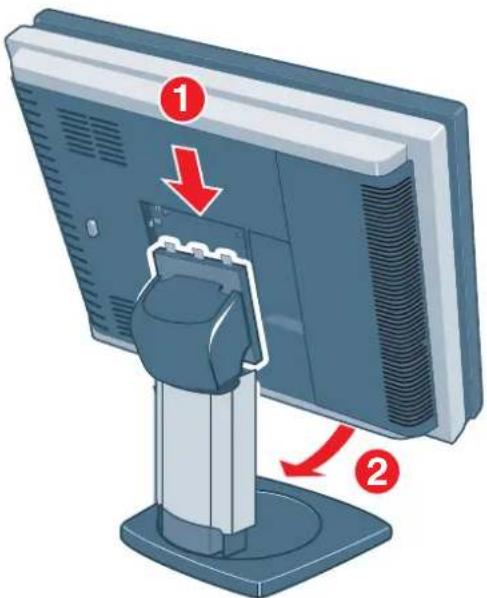
Illustration of a computer monitor with a stand and a labeled component (no text or symbols present)- Hookthetopgapsintherearofthepaneloverthetopanchorsofthestandattachmentplate(1).
- Push the bottom of the panel firmly towards the stand so that the bottom anchors clip in the bottom gaps(2).
- Check that the panel is firmly attached to the stand.
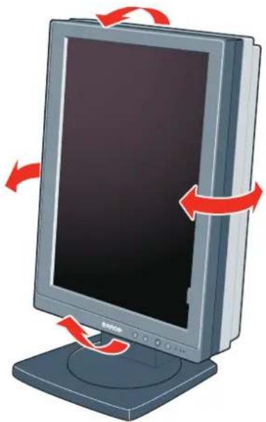
- Tilt and swivel the panel to the desired position and angle.
natural_image
Illustration of a computer monitor with red arrows indicating rotation or move, no text or symbols presentUsingthesingletilt&swivelfoot(landscapeorientation)
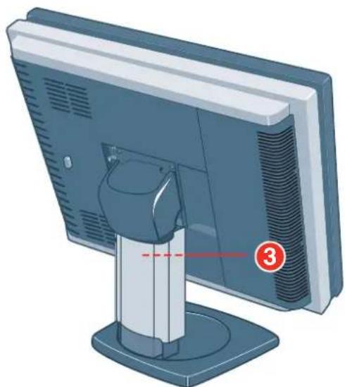
- Followthesamestepsasfortheportraitinstallationbutholdthedisplayinlandscapepositiontohook thepanelonthefoot.
natural_image
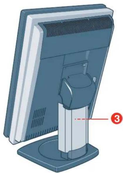
Illustration of a computer monitor with a stand and a numbered annotation (3) pointing to the screen area, no text or symbols present.Toreleasethepanelfromthedisplayfoot:
- Pushthepush-butt on(3)attherearofthepanel.
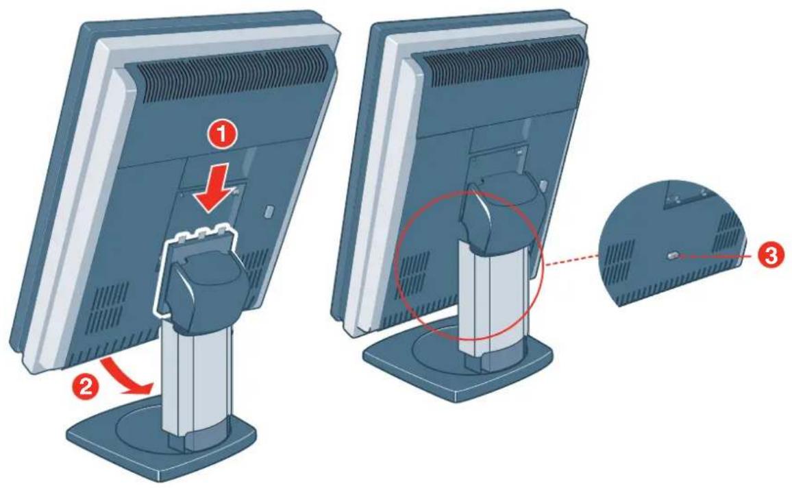
- Pull the bottom of the panel towards you and at the same time the panel from the stand attachment plate.
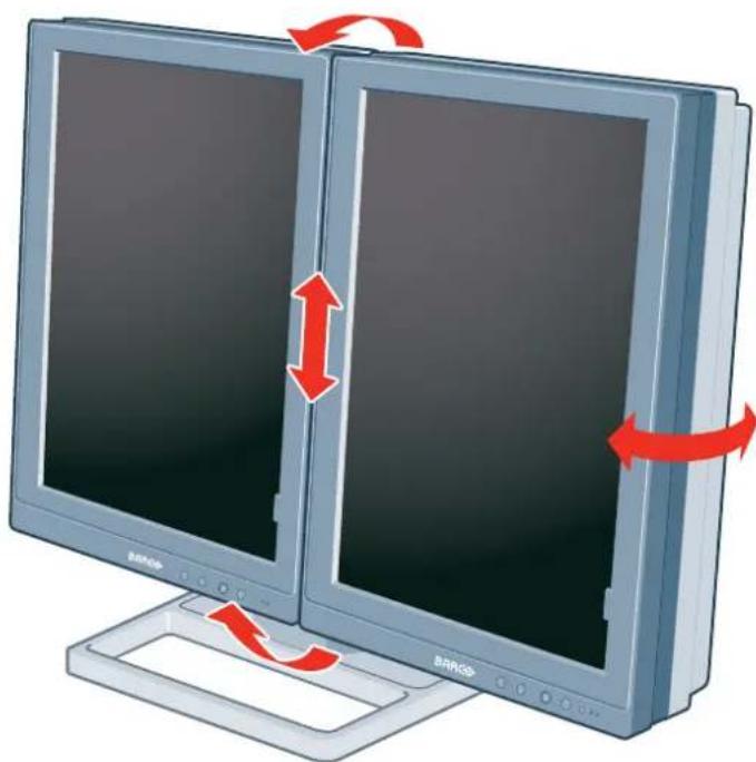
Usingthedualtilt&swivelfoot
-
Unpackthedualtilt&swivelfootandplaceitonasolidsurface.
-
Unpackthefirstdisplay.
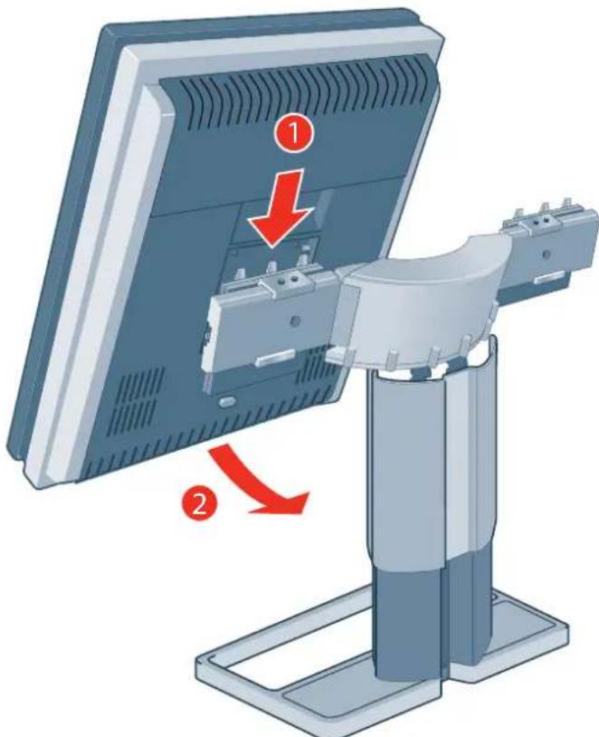
- Holdthedisplayslightlyangledwiththelogodownwardsandpositionthetopofthemountinganchor, atthebackofthedisplay,perfectlyalignedonthetopofthemountingclampofthefoot.
- Pushthedownsideofthedisplaygentlybackwardsu ntilthemountingclamplocksintothemounting anchor.
- Verify that mounting clamp and mounting anchor are perfectly fitting and that the display is firmly mounted.
- Repeatstep2 to 5 for these second display. Caution: Limit transportation distances of the same unted displays and foot system.
- Pullout the footlock clip.
- Retain theclip for possible further transportations.
- Now that the height-positioning is unlocked, you can adjust the position of the displays.
natural_image
Illustration of two computer monitors with red directional arrows indicating rotation or data transfer (no text or symbols present)Note: When both displays are not correctly aligned, minor corrections are possible in relative height and relative angle, by loosening and tightening the opposite pair of fallenscrews (oppositesides or oppositediagonals) of the positioningsliders.
3.2 VESA-mountinstallation

ThedisplaymountinganchoriscompatiblewiththeVESA100mmstandard.

WARNING: Never move a display attached to an arm by pulling or pushing the display itself. Instead, makes sure that the arm is equipped with a VESA approved handle and usethistomovethedisplay.
Pleaserefertotheinstructionmanualofthearmformoreinformationandinstructions.

WARNING: Use an arm that is approved by VESA (according to the VESA 100 mm standard).
Use an arm that can support the weight of the display. Refer to the technical specifications of this display for the applicable cableweight.
Overview
ThedisplaymountinganchoriscompatiblewiththeVESA100mmstandard.
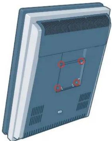
- Unscrewthefourfixationscrewsinthemountinganchor.
natural_image
3D rendering of a rectangular electronic device with a grid pattern and mounting holes (no text or symbols visible)- Attach the display firmly to the VESA mounting bracket with 4 screws M4 x 10 mm. You should mount the display in portrait position. Landscape position is not supported.
3.3Removingthecovers
Removaloftheconnectorcompartmentcover
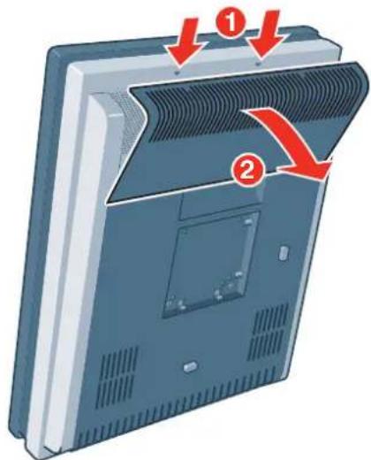
Theconnectorcompartmentcoversshouldberemovedtogetaccesstotheclockners. Toremovethe connectorcompartmentcover,proceedasfollows:
- Gentlypushthetwolipsontopofthecover.
- Pullthetopofthecoverslightlyawayfromthedisplayandlif tthecoverupwards.
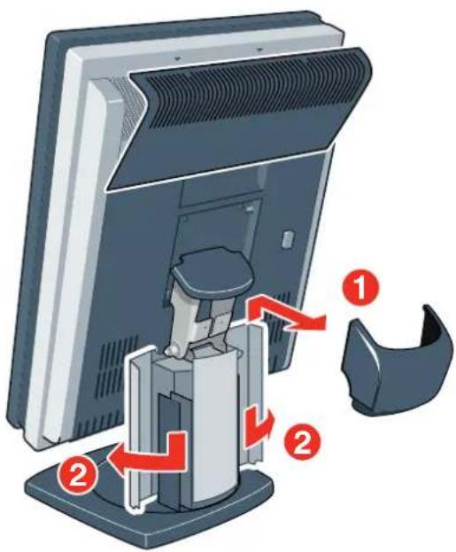
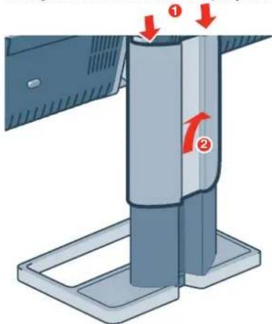
Removalofthecablecoversofasinglefoot
Togetaccesstothecableroutingchannelofasinglefoot, thecablecoversshouldberemoved. Toremove them, proceedasfollows:
-
Removethetilt&swivelnec kcover(1). Therefore, firsttiltthedisplaypanelinuprightposition. Then liftandpullbackwardtheneckcover.
-
Alsotofacilitatecableroutingafterwards, openbothcableductcovers(2).
Removalofthecablecoverofadualfoot
Togetaccesstothecableroutingchannelofadualfoot, thedisplaystandcablecoversshouldberemoved. Toremovethiscover, proceedingsfollows:
- Gentlypressandholdthelockclipsattheinsideofthetopofthecover.
- Slidethecoverupwardsontheshaftwhileholdingtheclipspressed. Itmaybeneededtotiltthedisplaysifthearmisblockingthemovementofthecover.
3.4 Connecting the signal cables

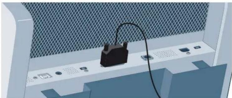
CAUTION: Only connect one of the two video links. Connecting both inputs simultaneously will result in driver errors.
Toconnectthesignalcablestothedisplay:
YoumayconnectthedisplaytoadisplaycontrollerbyusingtheDVIortheDPconnection. Theactive inputcanbeselectedintheOSDmenu.
- ConnecttheDVlorDPofthedisplaycontrollertotheDVlorDPconnectorofthedisplay.
natural_image
3D illustration of a computer monitor with an attached black device and cable, placed on a perforated screen (no text or symbols visible)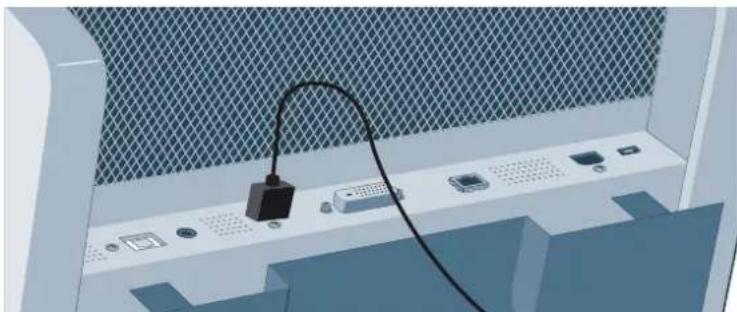
natural_image
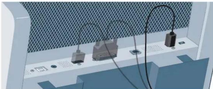
Illustration of an electronic device with a black cable and ports, mounted on a panel (no text or symbols visible)- If you want to make use of the display's USB downstream connectors, connect a PC USB downstream connector to the display's USB upstream connector.
natural_image
3D illustration of electronic components mounted on a panel with mesh background (no text or symbols)-
If you have chosen usethedisplay's USB downstream connectors, connect a USB device to one of the downstream connectors.
-
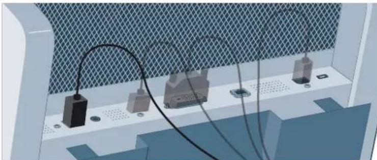
Connect the supplied external DC powers supply to the +24 VDC power input of the display.
natural_image
3D diagram of a mechanical or electrical setup with labeled components and wiring, no readable text or symbols present.- Plug the mains connector of the external DC power supply to a grounded power outlet by means of the supplied powercable.
3.5Routingthecables
Toroutethecables
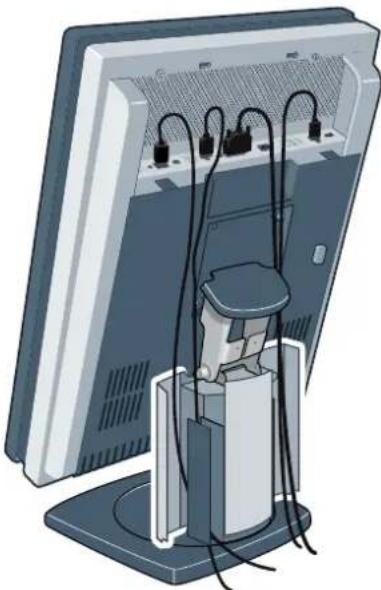
- Routethecablesalongsidetheneckandinthecableductsinthe
tilt&swivelfoot.
natural_image
Illustration of a computer monitor with cable routing and a stand (no text or symbols)- Re-attachtheconnectorcompartmentcoverandneckcover.Closethecableductcovers.Pushthe cableductcoversupwardstolockthem.
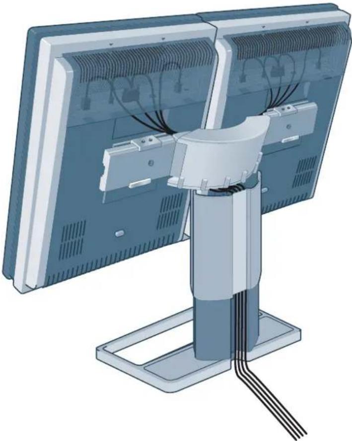
Toroutethecablesonadualfoot
Ifthedisplayismountedo nthesystemdualtilt&swivelfoot,cablesarebestroutedbehindthearmsand throughthecablechannelinthefootshaft,asshowninthepicturesbelow.
natural_image
Illustration of a computer monitor with cable routing and a mechanical arm attachment (no text or symbols)3.6Firsttimestartingup
Overview
YouarenowreadytostartupyourCoronis5MPforthefirsttime.
1.SwitchonyourCoronis5MPasdescribedin"Standbyswitching",page18.
2. Turnonthecomputerconnectedtoyourdisplay.
If you have properly installed your display and display controller, the Windows start-up messages will appear on the boot procedure is finished.

YourCoronis5MPwillberunninginabasicvideomodeatadefaultrefreshratewhen firsttimestartingup.IfyouareusingaBarcodisplaycontroller,pleaseconsulttheuser guidedeliveredwithittoinst allthedrivers,softwareanddocumentation.Whenthis isdone,yourdisplaywillautomaticallydetecttheconnectedvideoinputsignal(s)and applythecorrectvideomodeandrefreshrate.
4. DAILY OPERATION
4.1 Recommendationsfordailyoperation
Optimizethelifetimeofyourdisplay
EnablingtheDisplayPowerManagementSystem(DPMS)ofyourdisplaywilloptimizeitsdiagnosticlife-time by automatically switching off the backlight when the display is not used for a specified period of time. Bydefault,DPMSisenabledonyourdisplay,butitalsoneedstobeeactivatedonyourworkstation.Todo this,goto"PowerOptionsProperties"inthe"ControlPanel".

BarcorecommendssettingDPMSactivationafter20minutesofnon-usage.
Useascreensavertoavoidimageretention
ProlongedoperationofanLCDwiththesamecontentonthesamescreenareamayresultinaformofimageretention.
You can avoid or significantly reduce the occurrence of this phenomenon by using a screen saver. You can activate as screensaverinthe "Displayproperties" windowofyourworkstation.

Barcorecommendssettingscreensaveractivationafter5minutesofnon-usage.A goodscreensaverdisplaysmovingcontent.
In case you are working with the same image or an application with static image elements for several hours continuously (so that the screen saver is not activated), change the image content regularly to avoid image retentionofthestaticelements.
Understandpixeltechnology
LCDdisplaysusetechnologybasedonpixels.AsanormaltoleranceinthemanufacturingoftheLCD,a limitednumberofthesepixelsmayremaineitherdarkorpermanentlylit,withoutaffectingthediagnostic performance of the product. To ensure optimal product quality, Barco applies strict selection criteria for its LCDpanels.

TolearnmoreaboutLCDtechnologyandmissingpixels,consultthededicatedwhite papersavailableatw_ww.barco.com/healthcare.
Enhanceusercomfort
Every Barco multi-head display system is color matched with the highest specifications in the market.

Barcorecommendskeepingcolor-matcheddisplay together. Furthermore, it is important to use all displays of a multi-head configuration at the same rate to preserve color matching throughout the economic lifetime of the system.
Maximizequalityassurance
The 'MediCalQAWeb'systemoffersonlineserviceforhigh-gradeQualityAssurance,providingmaximum diagnosticconfidenceanduptime.

BarcorecommendstoinstallMediCalQAWebAgentandapplythedefaultQAWebpolicy atleast.Thispolicyincludescalationonregularintervals.ConnectingtoMediCalQAWebServeroffersevenmorepossibilities.
LearnmoreandsignupforthefreeMediCalQAWebEssentiallevelat www.barco.com/healthcare/qa.
4.2Keyindicatorlights
Aboutthekeyindicatorlights
Bydefault, the indicator light so the keys will be dimmed which make the keys un available at that moment. Tomakethe keysilluminate and available for further actions such one of the keys. As a result, all keys will be illuminated and are now available for further actions. However, if no further actions are taken within the following 5 seconds, the keys will dim again.

Thekeyauto-dimfunctioncanbedisabledintheOSDmenus.Pleaserefer dicatorlights",page22fordetailedinstructionsonhowtodothis.
to"Keyin-
4.3 Standbyswitching
Aboutstandbyswitching

The connected powersupply als provides as switch that can be used to turn the power completely off. To use the display, please make sure to switch on this power supply. This can be done by pushing the on/off switch on the power supply into the “|” position.
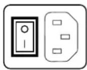
Switchingonthedisplaywhileitisinstandbymodeorviceversacanbedoneby:
- Illuminatethekeysaspreviouslydescribed.
- Whilethekeysareilluminated,touchthestandbykeyforapproximately2seconds.
As a result, the display will switch on or will switch to standby mode. When the display is switched on, the power LED is blue. When the display is in standby mode, the power LED is orange.

The power LED can be disabled in the OSD menus. Please refer to "Power status indicatorlight", page22fordetailedinstructionsonhowtodothis.

In case of a power outager recovery, your display will always start-up in the power mode it was in before the power interruption (i.e. standby or on). This protects your display against inadvertent imager retention problems.
4.4BringinguptheOSDmenus
HowtobringuptheOSDmenus
The OSD menu allows you to configure different settings to make your Coronis 5MP fit your needs within yourworkingenvironment.Also,youcanretrievegeneralinformationaboutyourdisplayanditscurrent configurationsettingsthroughtheOSDmenu.
BringinguptheOSDmenuscanbedoneby:
- If not already doneso, switch on the display as previously described.
- Illuminatethekeysaspreviouslydescribed.
- While the keys are illuminated, touch them menu key.
Asaresult, the OSD mainmenu comes up in the center of the screen. However, if no further actions are taken within the following 90 seconds, the OSD will disappear again.

The OSDmenuauto-exitfunctioncanbedisabledintheOSDmenu.Pleasereferto "OSDmenuautomaticclosefunction",page21fordetailedinstructionsonhowtodo this.

The OSD menu position can be modified in the OSD menu. Please refer to "OSD menu position", page21fordetailedinstructionsonhowtodothis.




4.5 Navigating through the OSD menus
HowtonavigatethroughtheOSDmenus
NavigatingthroughtheOSDmenuscanbedoneby:
- Usetheup/downkeystomovethroughthe(sub)menus,changevaluesormakeselections.
• To go into a submenu or confirm adjustments and selections, use the menu key.
• Usthestandbykeytocanceladjustmentsorexita(sub)menu. - ExitallOSDmenusatoncebytouchingthestandbykeyforapproximately2seconds.
Bydefault, the OSD menu comes up in the bottom center position of the screen. This position can be modified however. There's choice from a number of predefined positions.
TochangethepositionoftheOSDmenu:
- BringuptheOSDmainmenu.
- Navigate to the Configuration > User Interface > Menu menu.
3.EnterthePositionsubmenu. - SelectoneoftheavailableOSDmenupositionsandconfirm.
5.2OSDmenulanguage
AbouttheOSDmenulanguage
By default, the OSD menu comes up in English. However, there's a wide range of other languages available for the OSD menu of your Coronis5MP.
TochangethelanguageoftheOSDmenu:
- BringuptheOSDmainmenu.
- Navigate to the Configuration > User Interface menu.
3.EntertheLanguagesubmenu. - Selectoneoftheavailablelanguagesandconfirm.
5.3OSDmenuautomatic close function
AbouttheOSDmenuautomaticclosefunction
By default, the OSD menu will disappear automatically after approximately 90 seconds of inactivity. However, this function can be disabled so that the OSD menu remains on the screen until manually closed.
Toenable/disabletheOSDmenuautomaticclosefunction:
- BringuptheOSDmainmenu.
- Navigate to the Configuration > User Interface > Menu menu.
3.EntertheAutomaticClosesubmenu. - Select Enabled/Disabled as desired and confirm.
5.4 Powerstatusindicatorlight
About the power status indicator light
Bydefault, whenthedisplayisswitchedon, the power status indicator light is dimmed. This behavior can be changed so that the power status indicator light will be blue when the display is switched on.

Whenthedisplayisinstand-bymode,thepowerstatusindicatorlightwillalwaysturn orange,evenwhenthepowerstatusindicatorlightisdisabled.
Toenable/disablethepowerstatusindicatorlight:
- BringuptheOSDmainmenu.
- Navigate to the Configuration > User Interface > Indicator Lights menu.
3.EnterthePowerStatussubmenu. - Select Enabled/Disabled as desired and confirm.
5.5Keyindicatorlights
Aboutthekeyindicatorlights
Bydefault, afterlightingup, the key indicator lights will dim again if no further actions are taken within the following 5 seconds. However, this behavior can be changed so that the key indicator lights are always on oralway so off.
Toconfigurethekeyindicatorlights
- BringuptheOSDmainmenu.
- Navigate to the Configuration > User Interface > Indicator Lights menu.
3.EntertheKeyssubmenu. - Select Automatic/Always On/Always Off as desired and confirm.
5.6 Powerlockfunction
About the powerlock function
Byenabling the powerlock function, the Coronis5MP is forced to remain switched on. This means that it can't be switched to stand-by mode until the powerlock function is disabled again.
Toenable/disablethepowerlockfunction:
- BringuptheOSDmainmenu.
- Navigate to the Configuration > User Interface > Controls menu.
3.EnterthePowerLocksubmenu. - Select Enabled/Disabled as desired and confirm.
5.7Keyssound
Aboutkeyssound
Bydefault,thekeyswillmakea"beep"soundoneverytouch.However,thissoundcanbedisabledso thatnosoundwillbeheardwhenusingthekeys.
- BringuptheOSDmainmenu.
- Navigate to the Configuration > User Interface > Controls menu.
3.EntertheSoundsubmenu. - Select Enabled/Disabled as desired and confirm.
5.8EthernetoverUSB
AboutEth.overUSB
Bydefault,theEthernetoverUSBwillbedisabled.ThisdoesnotdisabletheUSBhubandstillallows tomakeuseofthedisplay'sUSBdownstreamconnectorsandanyexternaldevicesconnectedtoit(keyboard,mouse,...).
PleasenotethataconnectionfromaPCUSBdownstreamconnectortothedisplay'sUSBupstream connectorisrequiredtobeabletousethisfunctionality.
By enabling the Ethernet over USB, you allow the internal Coronis 5MP processor to communicate directly overUSBwiththeconnectedPC.

EnablingtheEthernetoverUSBisonlyrecommendedwhenyouareusinganon-Ba rco display controller. If you are using a Barco display controller, this communication will automatically bedoneovertheconnectedvideocable(s).
Toenable/disabletheeth.overUSB:
- BringuptheOSDmainmenu.
- Navigate to the Configuration > Connectivity menu.
3.EntertheEth.overUSB submenu. - Select Enabled/Disabled as desired and confirm.
5.9USB
AboutUSB
Bydefault, USBwillbeenabled. This will allow the connected PC to communicate directly over USB with the internal Coronis5MP processor.
BydisablingUSB, communicationbetweentheinternalCoronis5MPprocessorandtheconnectedPC willnotbepossible. ThisdoesnotdisabletheUSBhubandstillallowstomakeuseofthedisplay'sUSB downstreamconnectorsandanyexternaldevicesconnectedtoit(keyboard,mouse,...).
PleasenotethataconnectionfromaPCUSBdownstreamconnectortothedisplay'sUSBupstream connectorisrequiredtobeabletousethisfunctionality.

EnablingtheUSBendpointisonlyrecommendedwhenyouareusinganon-Barcodisplaycontroller.IfyouareusingaBarcodisplaycontroller,thiscommunicationwillautomaticallybedoneovertheconnectedvideocable(s).
- BringuptheOSDmainmenu.
- Navigate to the Configuration > Connectivity menu.
3.EntertheUSBsubmenu. - Select Enabled/Disabled as desired and confirm.
5.10DPMSmode
AboutDPMSmode
EnablingtheDisplayPowerManagementSystem(DPMS)modeonyourdisplaywilloptimizeitsdiagnostic lifetime by automatically switching off the backlight when the display is not used for a specified period of time. By default, DPMS modeisenabledonyourdisplay, butitalsoneedstobeeactivatedonyour workstation. Todo this, goto the "Poweroptionsproperties" window of your workstation.

BarcorecommendssettingDPMSactivationafter20minutesofnon-usage.

WhenDPMSmodeisenabledonyourdisplay,anadditionalOSDpowersavingfunction becomesavailable:hibernate.Pleasereferto"Hibernate",page24formoreinformation onhibernationandhowtoenablethisfunction.
Toenable/disableDPMSmodeonyourdisplay:
- BringuptheOSDmainmenu.
- Navigate to the Configuration > Power Management menu.
3.EntertheDPMSModesubmenu. - Select Enabled/Disabled as desired and confirm.
5.11Hibernate
Abouthibernate
Enablinghibernationwillnotonlyswitchoffthebacklightbutwillalsoforcethedisplaytodisableother functionalities so that power consumption is further reduced to a minimum. This happens after a specific periodoftimewhichcanbemanuallyadjusted.

Hibernate can only be enabled on your display when the DPMS mode is enabled first. Therefore, pleasereferto"DPMSmode", page2 4 to do this.
Toenable/disablehibernationonyourdisplay:
- BringuptheOSDmainmenu.
- Navigate to the Configuration > Power Management menu.
3.EntertheHibernate submenu. - Select Enabled/Disabled as desired and confirm.
Tospecifythehibernatetimeout:
- BringuptheOSDmainmenu.
- Navigate to the Configuration > Power Management menu.
3.EntertheHibernateTimeoutsubmenu. - Set the timeout value as desired and confirm.
5.12 Luminancetarget
Abouttheluminancetarget
The luminance target of your Coronis 5MP is adjustable over a predefined range. When you change the luminancetarget, the display will adjust its backlight to reach the target.
Tosettheluminancetarget:
- BringuptheOSDmainmenu.
- Navigate to the Configuration > Calibration menu.
- EntertheLuminanceTargetsubmenu.
- Setaluminancetargetvalueasdesiredandconfirm.

Thedefault, factory DICOM calibrated luminance value is available in the technical specifications table. The guaranteed backlight lifetime is valid for this setting.
5.13Viewingmodes
Aboutviewingmodes
TheCoronis5MPcanbeusedintwoviewingmodes:
| Diagnostic | Thismodeprovidesthefullcalibratedluminance andisintendedforusingthedisplayfordiagnostic purposes. |
| TextInthismode,theluminanceisreducedto | approximatelyhalfoftheluminance.This isintendedforusingthedisplaywithoffice applicationssuchaswordprocessing.Pleasenotethattextmodeisnotpersistent,once poweredoff,theunitwillrestartindiagnosticmode. |

AstheCoronis5MPisintendedtobeusedinadiagnosticenvironment,thediagnostic modeshouldalwaysbeselected.
Toselectaviewingmode:
- BringuptheOSDmainmenu.
- Navigate to the Configuration > Calibration menu.
- Enterthe ViewingModesubmenu.
- Select Diagnostic/Text as desired and confirm.
5.14Displayfunctions
Aboutdisplayfunctions
Native, uncorrected panels will display all grayscale color levels with luminance increment that are not optimal for crucial diagnostic information. Studies have shown however, that in medical images certain grayscale color parts contain more diagnostic information than others. To respond to these conclusions, display functions have been defined. These functions emphasize on these parts containing crucial diagnostic information by correcting thenative panel behavior.
| Native | IfyouselectNative,thenativepanelbehaviorwill notbecorrected. |
| DynamicGamma1.8 DynamicGamma2.2 | Thesearegammafunctionsthatareshiftedtotake intoaccountthenon-zeroluminanceofanLCD panelwhendrivenwitha“black”signal.Theyare especiallyusefulinCTapplicationstoimprovethe perceptionoflowHounsfieldvalues. |
| DICOMDICOM(DigitalImagingandCommunications | inMedicine)isaninternationalstandardthat wasdevelopedtoimprovethequalityand communicationofdigitalimagesinradiology.Inshort,theDICOMdisplayfunctionresultsin morevisiblegrayscalesintheimages.Barco recommendsselectingtheDICOMdisplayfunction formostmedicalviewingapplications. |
| User | Thisdisplayfunctionwillbeautomaticallyselected whendisplayfunctionsaredefinedbyMediCal QAWeb. |
| Gamma1.8 Gamma2.2 | Selectoneofthesedisplayfunctionsincasethe displayistoreplaceaCRTdisplaywithagamma of1.8or2.2respectively. |
Toselectadisplayfunction:
- BringuptheOSDmainmenu.
- Navigate to the Configuration > Calibration menu.
3.EntertheDisplayFunctionsubmenu. - Selectoneoftheavailabledisplayfunctionsandconfirm.
5.15 AmbientLightCompensation(ALC)
AboutALC

AmbientLightCompensation(ALC)canonlybeenabledonyourdisplaywhentheDI-COMdisplayfunctionisselected.Therefore,pleasereferto"Displayfunctions",page 26tocorrectlysetthedisplayfunction.
WhenALCisenabled,theDICOMdisplayfunctionwillberecalculatedtakingapresetambientlightcorrectionvalueintoaccount.Thisvalueisdeterminedbytheselectedreadingroom.Therefore,itisalso importanttoselectarealisticreadingroomwhenenablingALC.Thiscanbedonebyfollowingtheins tionsin"Readingrooms",page27.
truc-
- BringuptheOSDmainmenu.
- Navigate to the Configuration > Calibration > Ambient Light menu.
3.EntertheAmbientLightCompensationsubmenu. - Select Enabled/Disabled as desired and confirm.
5.16 Readingrooms
Aboutreadingrooms

ReadingroomscanonlybeselectedwhentheDICOMdisplayfunctionisselected. Therefore, pleasereferto"Displayfunctions",page26tocorrectlyset thedisplay function.
The American Association of Physicists in Medicine (AAPM) composed a list of pre-defined reading rooms. Eachofthesereadingroomsaredefinedbyfollowingparameters:
• themaximumlightallowedinthistypeofroom
- thepresetambientlightcorrectionvalueforthisreadingroom
Theseparametersarestoredinyourdisplayanddeterminethepresetambientlightcorrectionvalueto takeintoaccounttorecalcatetheDICOMdisplayfunctionwhenAmbientLightCompensation(ALC)is enabled. Pleasereferto"AmbientLightCompensation(ALC)",page27toenableALC.
TheavailablereadingroomsforyourCoronis5MPare:
| CR/DR/MAMMO | Correspondstolightconditionsindiagnostic readingroomsforcomputedradiology,digital radiologyormammography. Thissettinghasthe lowestmaximumambientlight. |
| CT/MR/NM | Correspondstolightconditionsindiagnostic readingroomsforcomputedtomography,magnetic resonanceornuclearmedicinescans. |
| Staff Office | Corresponds to light conditions in office rooms. |
| ClinicalViewingRoom | Correspondstolightconditionsindiagnostic readingroomsforclinicalviewing. |
| EmergencyRoom | Correspondstolightconditionsinemergency rooms. |
| OperatingRoom | Correspondstolightconditionsinoperatingrooms. Thissettinghasthehighestmaximumambientlight. |
Toselectareadingroom:
- BringuptheOSDmainmenu.
- Navigate to the Configuration > Calibration > Ambient Light menu.
- EntertheReadingRoomsubmenu.
- Selectoneoftheavailablereadingroomsandconfirm.
5.17ContinuousALC
AboutContinuousALC

ContinuousALCcanonlybeselectedwhentheDICOMdisplayfunctionisselected. Therefore, pleasereferto"Displayfunctions",page26tocorrectlysetthedisplayfunction.
EnablingcontinuousALCwillcontinuouslyrecalculatedtheDICOMdisplayfunctiontakingtheaveraged ambientlightintoaccount.
ToselectcontinuousALC:
- BringuptheOSDmainmenu.
- Navigate to the Configuration > Calibration > Ambient Light menu.
3.EntertheContinuousALCsubmenu. - Select Enabled/Disabled as desired and confirm.
5.18 Imagescaling
Aboutimagescaling
Enablingimagescalingwillmultiplyeachindividualpixeltooneormoreadjacentpixelssothatthesize ofthedisplayedimagewillbeamultipleoftheoriginalimagesourcevideoinputsignal.

Image scaling is only possible when the resolution of your display's video input signal is less than equal to half the maximum resolution of the display.
- BringuptheOSDmainmenu.
- Navigate to the Configuration > Image Source menu.
3.EntertheScalingsubmenu. - Select Enabled/Disabled as desired and confirm.
5.19 Displayorientation
AboutDisplayorientation
Yourdisplayautomaticallydetectsitsphysicalorientation(portraitorlandscape)and,bydefault,automaticallyadjuststheimageorientationtothis.Thismeansthatwhenyourdisplayisphysicallyrotated,theimagewillrotatealong.
The OSD menuhowever, allowstooverrulethisbehaviorandforcetheimageorientationtoportraitor landscaperegardlessofthephysicalorientationofthedisplay. Thismaybeespeciallyusefulwhenoperatingyourdisplaywiththescreenfacingupwards.
TosettheDisplayorientation
- BringuptheOSDmainmenu.
- Navigate to the Configuration > Image Sources menu.
3.EntertheDisplayOrientationsubmenu. - Select Landscape/Portrait/Automatic as desired and confirm.
5.20 Videoinputsignals
Aboutinputsignals
The available inputs signals for your display are:
| DisplayPort1TheinputcorrespondingtotheDisplayPort | connector. |
| DVI1TheinputcorrespondingtotheDVIconnector. | |
| AutomaticSelection | Theinputisautomaticallyselected. |
Tomanuallyselectavideoinputsignal:
- BringuptheOSDmainmenu.
- Navigate to the Configuration > Image Source menu.
3.EntertheInputSignalsubmenu. - Selectoneoftheavailableinputsignalsandconfirm.
5.21 Videoencoding modes
Aboutvideoencodingmodes
Videoencodingmodesspecifyhowthecolorandluminanceinformationisencodedinthevideosignal. Inconsumerdisplays, thisisusuallydonebyalimited8-bitencodingmechanism. YourCoronis5MP however, features 10-bit encoding enabling it to better match the DICOM defined grayscale range. Such anextensiverangeisnecessarytocomplywith theguidelinessetforwardbythelatestmedicalguidelines.
The available video encoding modes for your display are listed below.

Pleasenotethatthedisplaycontrollerconnectedtoyourdisplaymightnotalwayssupportallthesevideoencodingmodes.
| Standard | Thismodeusesthestandard8bitencoding mechanism. |
| HDR1 | Thismodefeatures10-bitvideoencodingfollowing theHighDynamicRange(HDR)standard,usually usedoncolordisplays. |
| HDR2 | HDR2isaBarcospecificmodefeaturing10-bit videoencodingfollowingtheHighDynamicRange (HDR)standardbutallowingfullrefreshrate(which isnotalwayspossiblewithHDR1).Thismodeis usuallyusedoncolordisplays. |
| Dual 10 (only with Barco display controller) | Dual 10 is a Barco specific 10-bit video encoding modewhichisusuallyusedongrayscaledisplays andwhichallowsfullrefreshrate. |
| Automatic | Whenselectingthisoption,yourCoronis5MPwill automaticallyassignthecorrectvideoencoding settingstothecconnectedvideoinputsignals. |
Tomanuallyselectavideoencodingmode:
- BringuptheOSDmainmenu.
- Navigate to the Configuration > Image Source menu.
- Enterthe VideoEncodingsubmenu.
- Selectoneoftheavailablevideoencodingmodesandconfirm.
5.22Grayscaleconversionmodes
Aboutgrayscaleconversionmodes
Grayscaleconversionmodesspecifyhowcolorgeneratedonthedisplaycontrollerisconvertedto grayscaleinyourdisplay.
The availablegrayscaleconversionmodesare:
| NoConversion | |
| UseRedChannelThismodeisintendedforgrayscaledisplayswheregrayissentovertheredchannel. | |
| UseGreenChannelThismodeisintendedforgrayscaledisplayswheregrayissentoverthegreenchannel. | |
| UseBlueChannel | Thismodeisintendedforgrayscaledisplayswheregrayissentoverthebluechannel. |
| UseAllChannels | Thismodeisintendedforgrayscaledisplayswheregrayissentoverthered,greenandbluechannel.Thisisdonebymeansofastandard conversion mechanismwhere30%red,59%greenand11% blueareusedtogenerategray. |
Tomanuallyselectagrayscaleconversionmode:
- BringuptheOSDmainmenu.
- Navigate to the Configuration > Image Source menu.
- Enter the Grayscale Conversions submenu.
- Selectoneoftheavailablecolorconversionmodesandconfirm.
5.23EDIDtimings
AboutEDIDtimings
FollowingEDIDtimingsareavailableforyourCoronis5MP:
| RefreshRateAllowstomanuallyselecttherefreshrateoftheimagesourcevideoinputsignaldependingonthmaximumrefreshrateofthedisplaycontrollerconnectedtoyourdisplay. | |
| PreferredOrientationAllowstochangetheorientationoftheimagesourcevideoinputsignaltolandscape,portraitortoletthedisplayautomaticallyassignthecorrectorientation. | |
| ColorDepthAllowstochangethecolordepthto8orto10bit. |
TomanuallysetEDIDtimings:
- BringuptheOSDmainmenu.
- Navigate to the Configuration > Image Source menu.
- Enterthe Timingssubmenu.
- Select Refresh Rate, Preferred Orientation or Color Depth.
- Selectoneoftheavailablesettingsandconfirm.
5.24Displayinfo
Aboutdisplayinfo
Your display serial number, color type, native resolution, firmware versions, etc. are available in a dedicated submenu of the OSD menu.
Toretrieveinfoaboutyourdisplay:
- BringuptheOSDmainmenu.
- Navigate to the About this Display menu to make the information visible on the screen.
5.25Displaystatus
Aboutdisplaystatus
TheStatussubmenuoftheOSDmenuprovidesinfoonthecurrentstatusofyourdisplay(runtimes,temperatures,etc.),thestatusoftheconnectedimagesources(videoencodingmode,timings,etc.),the currentcalibrationstatusofyourdisplay(displayfunction,luminance,ALC,etc.)andthestatusabout activatedconnections.
Toretrievethestatusofyourdisplay:
- BringuptheOSDmainmenu.
- NavigatetotheStatusmenu.
- Enter the Display, Image Sources, Calibration or Connectivity submenu as desired.
6.CLEANINGYOURDISPLAY
6.1 Cleaning instructions
Tocleanthedisplay
Cleanthedisplayusingasponge, cleaningclothorsofttissue, lightly moistened with arecognizedcleaningproductformedicalequipment. Read and follow all label instructions on the cleaning product. In case of doubt about acertain cleaning product, use plain water.
Donotusefollowingproducts:
•Alcohol/solventsathigherconcentration>5%
•Strongalkalislye,strongsolvents
- Acid
•Detergentswithfluoride
•Detergentswithammonia
•Detergentswithabrasives
•Steelwool
•Spongewithabrasives
•Steelblades
•Clothwithsteelthread

CAUTION: Take care not to damage or scratch the front glass or LCD. Be careful with ringsorotherjewelryanddonotapplyexcessivepressureonthefrontglassorLCD.

CAUTION: Do not apply or spray liquid directly to the display as excess liquid may cause damagetointernalelectronics. Instead, applytheliquidtoacleaningcloth.
7. IMPORTANT INFORMATION
7.1 Safetyinformation
General recommendations
Readthesafetyandoperatinginstructionsbeforeoperatingthedevice.
Retainsafety and operating instructions for further reference.
Adheretoallwarningsonthedeviceandintheoperatinginstructionsmanual.
Followwallinstructionsforoperationanduse.
ElectricalShockorFireHazard
To prevent electric shock or fire hazard, do not remove cover.
No serviceable parts inside. Refer servicing to qualified personnel.
Donotexposethisapparatustorainormoisture.
Typeofprotection(electrical):
Displaywithexternalpowersupply:Classlequipment.
Degreeofsafety(flammableanestheticmixture):
Equipment not suitable for use in the presence of a flammable anesthetic mixture with air or with oxygen ornitrousoxide.
Non-patientcareequipment
- Equipment primarily for use in a health care facility that is intended for use where contact with a patient is unlikely(noappliedpart).
• Theequipmentmaynotbeusedwithlifesupportequipment. - The user should not touch the equipment, nor its signal input ports (SIP)/signal output ports (SOP) and the patient at the same time.
Power connection – Equipment with external 24 VDC power supply
- Power requirements: The equipment must be powered using the delivered medical approved 24 VDC (——)SELVpowersupply.
- ThemedicalapprovedDC( ——)powersupplymustbepoweredbytheA Cmainsvoltage.
- The power supply is specified as a part of the ME equipment or combination is specified as a ME system.
• Toavoidtheriskofelectricshock, this equipmentmu stonlybeconnectedtoasupplymainswith protectiveearth.
• Theequipmentshouldbeinstallednearaneasilyaccessibleoutlet.
• Theequipmentisintendedforcontinuousoperation.
Transientover-voltage
If the device is not used for a long time, disconnect it from the AC inlet to avoid damage by transient over-voltage.
Tofullydisengagethepowertothedevice, pleasedisconnectthepowercordfromtheACinlet.
Powercords:
- UtilizeaUL-listeddetachablepowercord,3-wire,typeSJorequivalent,18AWGmin.,rated250V min., provided with a hospital-grade type plug 5-15P configuration for 120V application, or 6-15P for 240Vapplication.
- Do not overload wall outlets and extension cords as this may result in fire or electric shock.
- Mainsleadprotection(U.S.:Powercord):Powercordsshouldberoutedsothattheyarenotlikelyto bewalkeduponorpinchedbyitemsplaceduponoragainstthem,payingparticularattentiontocords atplugsandreceptacles.
- Thepowersupplycordshouldbereplacedbythedesignatedoperatoronlyatalltime.
- Useapowercordthatmatchesthevoltageofthepoweroutlet,whichhasbeenapprovedandcomplies withthesafetystandardofyourparticularcountry.
Waterandmoisture
Neverexposethedisplaytorainormoisture.
Neverusethedisplaynearwater-e.g.nearabathtub,washbasin,swimmingpool,kitchensink,laundry tuborinawetbasement.
Ventilation
Donotcoverorblockanyventilationopeningsinthecoveroftheset. Wheninstallingthedeviceina cupboardoranotherclosedlocation,heedthenecessaryspacebetweenthesetandthesidesofthe cupboard.
Installation
Place the device on a flat, solid and stable surface that can support the weight of at least 3 devices. If you use an unstable cartor stand, the devicemayfall, causing serious injury toachildor adult, and serious damage to the device.
Thisapparatusconformsto:
CE0120(MDD93/42/EEC;A1:2007/47/ECclassIIbproduct),CE-2004/108/EC,CE-93/42/EEC; A1:2007/47/ECclassIIb,IEC60950-1:2005+A1:2009(2NDEDITION),IEC 60601-12NDED:1988 + A1:1991 + A2:1995, UL 60601-1 1ST EDITION, CAN/CSA-C22.2 NO. 601.1-M90:2005, IEC 60601-1:2005 + A1:2012, ANSI/AAMI ES 60601-1:2005 + C1:2009 + A1:2012, CAN/CSAC22.2 No. 60601-1-08:2008, DEMKO-EN60601-1:2006, EN60601-1-2:2007, CCC-GB9254-2008+ GB4943-2001+GB17625.1-2003,KC,VCC,FCCclassB,ICES-001LevelB,FDA510K,RoHS
NationalScandinavianDeviationsforCL.1.7.2:
WasteElectricalandElectronicEquipment

Thissymbolontheproductindicatesthat, undertheEuropeanDirective2012/19/EUgoverning wastefromelectricalandelectronicequipment,thisproductmustnotbedisposedofwithothermunicipal waste.Pleasedisposeofyourwasteequipmentbyhandingitovertoadesignatedcollectionpointforthe recycling of waste electrical and electronic equipment. To prevent possible harm to the environment or
humanhealthfromuncontrolledwastedisposal,pleaseseparatetheseitemsfromothertypesofwaste andrecyclethemresponsiblytopromotethesustainablereuseofmaterialresources.
For more information about recycling of this product, please contact your local city office or your municipal wasted disposalservice.
Fordetails, please visit the Barcowebsite at: h http://www.barco.com/en/AboutBarco/weee
MercuryNotice

LAMP CONTAINS MERCURY, DISPOSE ACCORDING TO STATE/LOCAL LAW.
ThisBarcoproductconsistsofmaterialsthatmaycontainmercury,whichmust
berecycledordisposedofinaccordancewithlocal,state,orcountrylaws:
- Within this system, the lamps in the device contain mercury
TurkeyRoHScompliance

[RepublicofTurkey:InconformitywiththeWEEERegulation]
中国大陆 RoHS
ChineseMainlandRoHS
According to the "China Administration on Control of Pollution Cause by Electronic Information Products" (Alsocalled RoHSofChinese Mainland), the table below lists these names and content so toxic and/or hazardous substances that Barco's product may contain. The RoHSofChinese Mainland is included in the MCV standard of the Ministry of Information Industry of China, in these section "Limit Requirements of toxic substances in Electronic Information Products".
| 零件项目(名称)Componentname | 有毒有害物质或元素Hazardoussubstancesandelements | |||||
| 铅Pb | 汞Hg | 镉Cd | 六价铬Cr6+ | 多溴联苯PBB | 多溴二苯醚PBDE | |
| 印制电路配件PrintedCircuitAssemblies | x | o | o | o | o | o |
| 液晶面板LCDpanel | x | x | o | o | o | |
| 外接电(线)缆ExternalCables | x | o | o | o | o | o |
| 内部线路Internalwiring | o | o | o | o | o | |
| 金属外壳Metalenclosure | o | o | o | o | o | |
| 塑胶外壳Plasticenclosure | o | o | o | o | o | |
| 散热片(器)Heatsinks | o | o | o | o | o | |
| 电源供应器PowerSupplyUnit | x | o | o | o | o | o |
| 风扇Fan | o | o | o | o | o | |
| 文件说明书PaperManuals | o | o | o | o | o | |
| 光盘说明书CDmanual | o | o | o | o | o | |
| O:表示该有毒有害物质在该部件所有均质材料中的含量均在SJ/T 11363-2006标准规定的限量要求以下.O:IndicatesthatthistoxicorhazardoussubstancecontainedinallofthehomogeneousmaterialsforthispartisbelowthelimitrequirementinSJ/T11363-2006. | ||||||
| X:表示该有毒有害物质至少在该部件的某一均质材料中的含量超出SJ/T 11363-2006标准规定的限量要求.X:IndicatesthatthistoxicorhazardoussubstancecontainedinalestoneofthehomogeneousmaterialsusedforthispartisabovethelimitrequirementinSJ/T11363-2006 | ||||||
AllElectronicInformationProducts(EIP)thataresoldwithinChineseMainlandmustcomplywiththe "ElectronicInformationProductsPollutionControlLabelingStandard"ofChineseMainland,markedwith theEnvironmentalFriendlyUsePeriod(EFUP)logo. ThenumberinsidetheEFUPlogothatBarcouses (pleaserefertothephoto)isbasedonthe"StandardofElectronicInformationProductsEnvironmental FriendlyUsePeriod"ofChineseMainland.

7.3 Regulatory compliance information
Indicationsforuse
TheCoronis5MP(MDCG-5121)isintendedtobeusedindisplayingandviewingdigitalimages,including digital mammography, for review and analysis by trained medical practitioners. Caution (USA): Federal lawrestrictsthisdevicetosalebyorontheorderofaphysician.(Details&exemptionsareintheCode ofFederalRegulationsTitle21,801PartD).
FCCclassB
This device complies with Part 15 of the FCC Rules. Operation is subject to the following two conditions: (1) this device may not cause harmful interference, and (2) this device must accept any interference received, including interference that may cause undesired operation.
This device has been tested and found to comply with the limits for a Class B digital device, pursuant to Part 15 of the FCC Rules. These limits are designed to provide reasonable protection against harmful interference in a residential installation. This device generates, uses and can radiate radio frequency energy and, if not installed and used in accordance with the instructions, may cause harmful interferon to radiocommunications. However, there is no guarantee that interference will not occur in particular installation. If this device does cause harmful interferencetoradioortelevision reception, which can be determined by turning the device off and, the user is encouraged to try to correct the interference by one or more of the following measures:
rence
•Reorientorrelocatethereceivingantenna.
- Increase these separation between the device and receiver.
- Connectthedeviceintoanoutletonacircuitdifferentfromthattowhichthereceiverisconnected.
- Consultthedealeroranexperiencedradio/TVtechnicianforhelp.
Changes or modifications not expressly approved by the party responsible for compliance could void the user's authority to operate the equipment.
Canadiannotice
ThisISMdevicecomplieswithCanadianICES-001.
CetappareilISMestconformeàlanormeNMB-001duCanada.
7.4EMCnotice
Generalinformation
No specific requirement on the use of external cables or other accessories except power supply.
Withtheinstallationofthedevice,useonlythedeliveredp ownersupplyorasparepartprovidedbythe legalmanufacturer.Usinganothercanresultinadecreaseoftheimmunitylevelofthedevice.
Electromagneticemissions
The Coronis 5MP is intended for use in the electromagnetic environment specified below. The customer ortheuseroftheCoronis5MPshouldassurethatitisusedinsuchanenvironment.
| Emissionstest | Compliance | Electromagneticenvironment-Guidance |
| RFemissionsCISPR11 | Group1 | TheCoronis5MPusesRFenergy onlyforitsinternalfunction.Therefore,itsRFemissionsare verylowandarenotlikelyto causeanyinterferenceinnearby electronicequipment. |
| RFemissionsCISPR11 | ClassB | TheCoronis5MPissuitable foruseinallestablishments, including domestic establishments andthosedirectlyconnectedto thepubliclow-voltagepower |
| HarmonicemissionsIEC61000-3-2 | ClassD | |
| Voltage fluctuations/ flicker emissionsIEC61000-3-3 | Complies | supplynetworkthatsupplies buildingsusedfordomestic purposes. |
ThisCoronis5MPcomplieswithappropriatemedicalEMCstandardsonemissionsto,andinterference fromsurroundingequipment.Operationissubjecttothefollowingtwoconditions:(1)thisdevicemaynot causeharmfulinterference,and(2)thisdevicemustacceptanyinterferencereceived,includinginterferencethatmaycauseundesiredoperation.
Interference can be determined by turning the equipment of fandon.
If this equipment does cause harmful interference, or suffer from harmful interference of, surrounding equipment, the user is encouraged to try to correct the interference by one or more of the following measures:
•Reorientorrelocatethereceivingantennaorequipment.
- Increase these separation between the equipment and receiver.
- Connecttheequipmentintoanoutletonacircuitdifferentfromthattowhichthereceiverisconnected.
- Consultthedealeroranexperiencedtechnicianforhelp.
Electromagneticimmunity
The Coronis 5MP is intended for use in the electromagnetic environment specified below. The customer ortheuseroftheCoronis5MPshouldassurethatitisusedinsuchanenvironment.
| Immunitytest | IEC60601Testlevels | Compliancelevel | Electromagnetic environment-guidance |
| Electrostaticdischarge (ESD)IEC61000-4-2 | ±6kVcontact± 8 k V a i r | ±6kVcontact± 8 k V a i r | Floorsshouldbewood, concreteorceramictile. Iffloorsarecoveredwith syntheticmaterial,the relativehumidityshould beatleast30% |
| Electricalfast transient/burstIEC61000-4-4 | ±2kVforpowersupply lines±1kVforinput/output lines | ±2kVforpowersupply lines±1kVforinput/output lines | Mainspowerquality shouldbethatofatypical commercialorhospital environment |
| SurgeIEC61000-4-5 | ±1kVline(s)toline(s)±2kVline(s)toearth | ±1kVline(s)toline(s)± 2 k V line (s) to e a n | Mainspowerquality shouldbethatofatypical commercialorhospital environment |
| Voltagedips,short interruptionsandvoltage variationsonpower supplyinputlinesIEC61000-4-11 | < 5 % U_T 1(>95%dipin U_T )for0.5cycle40% U_T (60% d i p i r) for5cycles70% U_T (30% d i p i r) for25cycles< 5 % U_T (>95%dipin U_T )for5s | < 5 % U_T (>95%dipin U_T )for0.5cycle40% U_T (60%dipin U_T ) for5cycles70% U_T (30%dipin U_T ) for25cycles< 5 % U_T (>95%dipin U_T ) for 5 s | Mainspowerquality shouldbythatofa typicalcommercialor hospitalenvironment.If theuseroftheCoronis 5MPrequirescontinued operationduringpower mainsinterruptions,itis recommendedthatthe Coronis5MPbepowered fromanuninterruptible powersupplyorabattery. |
| Powerfrequency(50/60 Hz)magneticfieldIEC61000-4-8 | 3 A/m | Notapplicable2 | Power frequency magneticfieldsshould beatlevelscharacteristic ofatypicallocationin atypicalcommercialor hospitalenvironment. |
| ConductedRFIEC61000-4-6 | 3 Vr m s150kHzto80MHz | 3V | Portableandmobile RFcommunications |
-
is the a.c. mains voltage prior to application of the test level.
-
Coronis 5MP doesn't contain susceptible components to magnetic fields
| Immunitytest | IEC60601Testlevels | Compliancelevel | Electromagnetic environment-guidance |
| RadiatedRFIEC61000-4-3 | 3 V/m80MHzto2.5GHz | 3 V/m | equipmentshouldbe usednoclosertoany partoftheCoronis 5MP,includingcables, thantherecommended separationdistance calculatedfromthe equationapplicable tothefrequency ofthetransmitter. Recommended separationdistance d = 1.2 d = 1.2 80MHzto800 MHz d = 2.3 800 MHz to 2.5 GhzWherePisthemaximum outputpowerrating ofthetransmitterin watts(W)according tothetransmitter manufacturerandistherecommended separationdistancein meters(m).Fieldstrengthsfrom fixedRFtransmitters, asdeterminedbyan electromagneticsite survey, ^3 shouldbeless thanthecompliance levelineachfrequency range. ^4 Interferencemayoccurin thevicinityofequipment markedwithsymbol: |

At80MHz and 800MHz, the higher frequency range applies.

These guidelines may not apply in all situations. Electromagnetic propagation is affected by absorption and reflection from structures, objects and people.
Recommendedseparationdistance
TheCoronis5MPisintendedforuseinanelectromagneticenvironmentinwhichradiatedRFdisturbances arecontrolled. ThecustomeroftheuseroftheCoronis5MPcanhelppreventelectromagneticinterferencebymaintainingaminimumdistancebetweenportableandmobileRFcommunicationsequipment (transmitters)andtheCoronis5MPasrecommendedbelow,accordingtothemaximumoutputpowerof thecommunicationsequipment.
| Ratedmaximumoutput poweroftransmitter 5 W | Separationdistanceaccordingtofrequencyoftransmitter | ||
| 150kHzto80MHz d=1.2√P | 80MHzto800MHz d=1.2√P | 800MHzto2.5GHz d=2.3√P | |
| 0.010.120.120.23 | |||
| 0.10.380.380.73 | |||
| 11.21.22.3 | |||
| 103.83.87.3 | |||
| 1 | 0 | 0 | 1 |

At80MHz and 800MHz, these separation distance for the higher frequency range applies.

These guidelines may not apply in all situations. Electromagnetic propagation is affected by absorption and reflection form structures, object and people.
7.5 Explanationofsymbols
Symbolsonthedevice
On the device or power supply, you may find the following symbols (nonrestrictive list):
| CE0120 | IndicatescompliancewiththeDirective93/42/EECasClassldevice |
| IndicatescompliancewiththeDirective93/42/EECasClassIldevice | |
| FC | IndicatescompliancewithPart15oftheFCCrules(ClassAorClassB) |
- For transmitters rated at a maximum output power not listed above, the recommended separation distance d in meters (m) can be estimated using the equation applicable to the frequency of the transmitter. Where P is the maximum output power rating of the transmitter in watts (W) according to the transmitter manufacturer.
 | IndicatesthedeviceisapprovedaccordingtotheULregulations |
 | IndicatesthedeviceisapprovedaccordingtotheULregulationsforCanada andUS |
 | IndicatesthedeviceisapprovedaccordingtotheULDemkoregulations |
 | IndicatesthedeviceisapprovedaccordingtotheCCCregulations |
 | IndicatesthedeviceisapprovedaccordingtotheVCCIregulations |
 | IndicatesthedeviceisapprovedaccordingtotheKCregulations |
 | IndicatesthedeviceisapprovedaccordingtotheBSMIregulations |
 | IndicatestheUSBconnectorsonthedevice |
 | IndicatestheDisplayPortconnectorsonthedevice |
 | Indicatesthemanufacturingdate |
 | Indicatesthetemperaturelimitations 6 forthedevicetosafelyoperatewithinspecs |
 | Indicatesthedeviceserialno. |
 | Warning:dangerousvoltage |
 | Caution |
 | Consulttheoperatinginstructions |
| Indicate this device must not be thrown in the trash but must be recycled, according to the European WEEE (Waste Electrical and Electronic Equipment) directive | |
| Indicates Direct Current (DC) | |
| Indicates Alternating Current (AC) | |
| Stand-by | |
| Equipotentiality |
7.6 Legaldisclaimer
Disclaimernotice
Although every attempt has been made to achieve technical ac curacy in this document, we assume responsibility for error that may be found. Our goalist provide you with the most accurate and usable documentation possible; if you discover errors, please let us know.
BarcosoftwareproductsarethepropertyofBarco. TheyaredistributedundercopyrightbyBarcoN.V.or Barco, Inc., for use only under the specific terms of a software license agreement between Barco N.V. or Barcolnc.andthelicensee.Nootheruse,duplication,ordisclosureofaBarcosoftwareproduct,inany form,isauthorized.
The specifications of Barco products are subject to change without notice.
Trademarks
Alltrademarksandregisteredtrademarksarepropertyoftheirrespectiveowners.
Copyrightnotice
Thisdocumentiscopyrighted.Allrightsarereserved.Neitherthisdocument,noranypartofit,may bereproducedorcopiedinanyformorbyanymeans-graphical,electronic,ormechanicalincluding photocopying,tapingorinformationstorageandretrievalsystems-withoutwrittenpermissionofBarco.
©2014BarcoN.V.Allrightsreserved.
Patentinformation
Thisproductiscoveredunderthefollowingintellectualpropertyrights:
USPatentRE43,707
USPatent7,038,186
USPatent7,166,829
USPatent6,950,098
EuropeanPatent1274066.
7.7 Technical specifications
Overview
| Productacronym | MDCG-5121 |
| ScreentechnologyTFTAMLCDD | DualDomainIPS |
| Activescreensize(diagonal)540.9mm(21.3") | |
| Activescreensize(HxV)422.4mm | x377.9mm(16.5"x13.3") |
| Aspectratio(H:V) | 5:4 |
| Resolution | 5MP(2560x2048) |
| Pixelpitch | 0.165mm(H)x0.165mm |
| Colorimaging | No |
| Grayimaging | Yes |
| Numberofgrayscales(LUT in/LUTout) | 1024graylevels(10/12) |
| Viewingangle(H,V)170° | |
| UniformLuminance Technology (ULT) | Yes |
| PerPixel Uniformity (PPU) | Yes |
| AmbientLightCompensation (ALC) | Yes |
| BacklightOutputStabilization (BLOS) | Yes |
| I-Guard | Yes |
| Maximumluminance | 1100cd/m2(paneltypical) |
| DICOMcalibratedluminance (ULToff) | 500cd/m2 |
| Contrastratio(ULToff) | 850:1typical |
| Responsetime(Tr+Tf) | 36mstypical |
| Scanningfrequency(H;V) | 30-150kHz;15-80Hz |
| Housingcolor | Gray |
| Video input signals | DVI-D Dual Link / DisplayPort (per display) |
| Videoinoutterminals | NA |
| USBports | 1upstream(endpoint),3downstream |
| USBstandard | 2.0 |
| Powerrequirements(nominal) | 100-240V |
| Power consumption (nominal) | 70W |
| Power savemode | Yes |
| Powermanagement | DVI-DMPM/DP-DMPM |
| Dotclock | 280MHz |
| OSDlanguages | English,German,French,Dutch,Spanish,Italian,Portuguese,Polish,Russian,Swedish,Chinese (simplified),Japanese,Korean,Arabic |
| Dimensionswithstand(WxH x D) | Portrait:(wxhmaxxd)392x658.2x110.2mm(wxhminxd)392x558.2 x 110.2 mm Landscape: (w x hmax x d) 484.7 x 565.5 x 110.2 mm(wxhminxd)484.7x465.5x110.2mm |
| Dimensionsw/ostand(WxH x D) | 392x484.7x110.2mm |
| Dimensionspackaged (WxH x D) | 779x542x255mm |
| Netweightwithstand | 15.3kg |
| Netweightw/ostand | 9.3kg |
| Netweightpackagedwith stand | N/A |
| Netweightpackagedw/ostand | 14.6kg |
| Heightadjustmentrange100mm | |
| Tilt | -5°/+25° |
| Swivel-45°/+45°Left/Right | |
| Pivot | N/A |
| Mountingstandard | VESA(100mm) |
| Screen protection | Protective, non-reflective glass cover |
| Recommendedmodalities | CT,MR,US,DR,CR,NM,Film |
| Certifications | CE0120 (MDD 93/42/EEC; A1:2007/47/EC class IIb product), CE -2004/108/EC,CE-93/42/EEC;A1:2007/47/ECclassIIb,IEC 60950-1:2005+A1:2009(2NDEDITION),IEC60601-12NDED:1988 +A1:1991+A2:1995,UL60601-11STEDITION,CAN/CSA-C22.2 NO.601.1-M90:2005,IEC60601-1:2005+A1:2012,ANSI/AAMI ES60601-1:2005+C1:2009+A1:2012,CAN/CSAC22.2No. 60601-1-08:2008,DEMKO-EN60601-1:2006,EN60601-1-2:2007, CCC-GB9254-2008+GB4943-2001+GB17625.1-2003,KC,VCC, FCCclassB,ICES-001LevelB,FDA510K,RoHS |
| Suppliedaccessories | UserGuide |
| QuickInstallationSheet | |
| Videocables(1xDVIDualLink+1xDisplayPort) | |
| Maincables(UK,European(CEBEC/KEMA),USA(UL/CSA;adaptor plugNEMA5-15P),Chinese(CCC)) | |
| USB2.0cable | |
| Externalpowersupply | |
| OptionalaccessoriesN/A | |
| QAsoftwareMediCalQAWeb | |
| Unitsperpallet | N/A |
| Palletdimensions(WxH) N/A | |
| Warranty | 5 years |
| Operatingtemperature | 0°Cto40°C(15°Cto35°Cwithinspecs) |
| Storagetemperature | -20°Cto60°C |
| Operatinghumidity | 8%-70%(non-condensing) |
| Storagehumidity | 5%-95%(non-condensing) |
| Operationaltitude | 3000m |
| Storagealtitude | 7500m |
7.8 Open source license information
Opensourcelicenseinformation
Opensourcelicenseusage
This product contains software components released under an Open Source license. A copy of the source codeisavailableonrequestbycontactingyourBarcocustomersupportrepresentative.
EACH SEPARATE OPEN SOURCE SOFTWARE COMPONENT AND ANY RELATED DOCUMENTATION ARE PROVIDED "AS IS" WITHOUT EXPRESS OR IMPLIED WARRANTY INCLUDING, BUT NOT
LIMITEDTO, THE IMPLIED WARRANTY OF MERCHANT ABILITY AND FITNESS FOR APARTICULAR PURPOSE. IN NO EVENT SHALL THE COPYRIGHT HOLDER OR ANY OTHER CONTRIBUTOR BE LIABLE FOR DIRECT, INCIDENTAL OR CONSEQUENTIAL DAMAGES, EVEN IF ADVISED OF THE POSSIBILITY OF SUCH DAMAGES. MORE INFORMATION/DETAILSISTOBEFOUNDINEACH SPECIFIC OPENSOURCE LICENSE.
CopyrightoneachOpenSourceSoftwarecomponentbelongstotherespectiveinitialcopyrightholder, each additional contributor and/or their respective assignee(s), as may be identified in the respective documentation, source code, README file, or otherwise. You shall not remove or obscure or otherwise alter therespectivecopyrights.
YouacknowledgelivinguptotheconditionsofeachseparateOpenSourceSoftwarelicense.
AlistoftheOpenSourceSoftwarecomponentsusedisavailableintheapplicableEULA,throughthe(customersectionofthe)Barcowebsiteorthroughother(online)means.
- 1.WELCOME!
- About the product
- Overview
- What's in the box
- 2.PARTS,CONTROLSAND CONNECTORS
- Displayfrontview
- Displayrearview
- 2.3Foot
- 3.DISPLAYINSTALLATION
- 3.1Mountingthedisplays
- Usingthesingletilt&swivelfoot(portraitorientation)
- Usingthesingletilt&swivelfoot(landscapeorientation)
- Toreleasethepanelfromthedisplayfoot:
- Usingthedualtilt&swivelfoot
- VESA-mountinstallation
- 3.3Removingthecovers
- Removaloftheconnectorcompartmentcover
- Removalofthecablecoversofasinglefoot
- Removalofthecablecoverofadualfoot
- Connecting the signal cables
- Toconnectthesignalcablestothedisplay:
- 3.5Routingthecables
- Toroutethecables
- Toroutethecablesonadualfoot
- 3.6Firsttimestartingup
- DAILY OPERATION
- Recommendationsfordailyoperation
- Optimizethelifetimeofyourdisplay
- Useascreensavertoavoidimageretention
- Understandpixeltechnology
- Enhanceusercomfort
- Maximizequalityassurance
- 4.2Keyindicatorlights
- Aboutthekeyindicatorlights
- Standbyswitching
- Aboutstandbyswitching
- 4.4BringinguptheOSDmenus
- HowtobringuptheOSDmenus
- Navigating through the OSD menus
- HowtonavigatethroughtheOSDmenus
- TochangethepositionoftheOSDmenu:
- 5.2OSDmenulanguage
- AbouttheOSDmenulanguage
- TochangethelanguageoftheOSDmenu:
- 5.3OSDmenuautomatic close function
- AbouttheOSDmenuautomaticclosefunction
- Toenable/disabletheOSDmenuautomaticclosefunction:
- Powerstatusindicatorlight
- About the power status indicator light
- Toenable/disablethepowerstatusindicatorlight:
- 5.5Keyindicatorlights
- Toconfigurethekeyindicatorlights
- Powerlockfunction
- About the powerlock function
- Toenable/disablethepowerlockfunction:
- 5.7Keyssound
- Aboutkeyssound
- 5.8EthernetoverUSB
- AboutEth.overUSB
- Toenable/disabletheeth.overUSB:
- 5.9USB
- AboutUSB
- 5.10DPMSmode
- AboutDPMSmode
- Toenable/disableDPMSmodeonyourdisplay:
- 5.11Hibernate
- Abouthibernate
- Toenable/disablehibernationonyourdisplay:
- Tospecifythehibernatetimeout:
- Luminancetarget
- Abouttheluminancetarget
- Tosettheluminancetarget:
- 5.13Viewingmodes
- Aboutviewingmodes
- AstheCoronis5MPisintendedtobeusedinadiagnosticenvironment,thediagnostic modeshouldalwaysbeselected.
- Toselectaviewingmode:
- 5.14Displayfunctions
- Aboutdisplayfunctions
- Toselectadisplayfunction:
- AmbientLightCompensation(ALC)
- AboutALC
- Readingrooms
- Aboutreadingrooms
- Toselectareadingroom:
- 5.17ContinuousALC
- AboutContinuousALC
- ToselectcontinuousALC:
- Imagescaling
- Aboutimagescaling
- Displayorientation
- AboutDisplayorientation
- TosettheDisplayorientation
- Videoinputsignals
- Aboutinputsignals
- Tomanuallyselectavideoinputsignal:
- Videoencoding modes
- Aboutvideoencodingmodes
- Tomanuallyselectavideoencodingmode:
- 5.22Grayscaleconversionmodes
- Aboutgrayscaleconversionmodes
- Tomanuallyselectagrayscaleconversionmode:
- 5.23EDIDtimings
- AboutEDIDtimings
- TomanuallysetEDIDtimings:
- 5.24Displayinfo
- Aboutdisplayinfo
- Toretrieveinfoaboutyourdisplay:
- 5.25Displaystatus
- Aboutdisplaystatus
- Toretrievethestatusofyourdisplay:
- 6.CLEANINGYOURDISPLAY
- Cleaning instructions
- Tocleanthedisplay
- IMPORTANT INFORMATION
- Safetyinformation
- General recommendations
- ElectricalShockorFireHazard
- Typeofprotection(electrical):
- Degreeofsafety(flammableanestheticmixture):
- Non-patientcareequipment
- Power connection – Equipment with external 24 VDC power supply
- Transientover-voltage
- Powercords:
- Waterandmoisture
- Ventilation
- Installation
- Thisapparatusconformsto:
- NationalScandinavianDeviationsforCL.1.7.2:
- MercuryNotice
- TurkeyRoHScompliance
- 中国大陆 RoHS
- Regulatory compliance information
- Indicationsforuse
- FCCclassB
- Canadiannotice
- 7.4EMCnotice
- Generalinformation
- Electromagneticemissions
- Electromagneticimmunity
- At80MHz and 800MHz, the higher frequency range applies.
- Recommendedseparationdistance
- Explanationofsymbols
- Symbolsonthedevice
- Legaldisclaimer
- Disclaimernotice
- Trademarks
- Copyrightnotice
- Patentinformation
- Technical specifications
- Open source license information
- Opensourcelicenseinformation
Brand : Barco
Model : Coronis 5MP
Category : Monitor