
MDNG-5121 - Monitor Barco - Free user manual and instructions
Find the device manual for free MDNG-5121 Barco in PDF.


| Product Type | Medical Diagnostic Monitor |
| Brand | Barco |
| Model | MDNG-5121 |
| Display Size | 21.5 inches (54.6 cm) |
| Resolution | 1920 x 1080 (Full HD) |
| Brightness | 300 cd/m² typical |
| Contrast Ratio | 1000:1 typical |
| Response Time | 8 ms (GtG) |
| Viewing Angle | 178° horizontal / 178° vertical |
| Color Gamut | sRGB 99% |
| Input Ports | 1 x DVI-D, 1 x DisplayPort 1.2, 1 x HDMI 1.4 |
| Power Consumption (Typical) | 35 W |
| Power Supply | 100-240 V AC, 50/60 Hz |
| Dimensions (with stand) | 514 x 380 x 205 mm (W x H x D) |
| Weight (without stand) | 5.5 kg |
| VESA Mount | 100 x 100 mm |
| Calibration | DICOM Part 14 compliant |
| Cleaning Instructions | Use a soft, lint-free cloth dampened with mild soapy water. Avoid solvents. |
| Safety Standards | IEC 60601-1, EN 60601-1 |
| Spare Parts Availability | Power supply unit, backlight LED driver board, fan (if any) |
| Warranty | 3 years (parts and labor) |
Frequently Asked Questions - MDNG-5121 Barco
User questions about MDNG-5121 Barco
0 question about this device. Answer the ones you know or ask your own.
Ask a new question about this device
Download the instructions for your Monitor in PDF format for free! Find your manual MDNG-5121 - Barco and take your electronic device back in hand. On this page are published all the documents necessary for the use of your device. MDNG-5121 by Barco.
USER MANUAL MDNG-5121 Barco
natural_image
Computer monitor displaying a grayscale medical image of breast tissue (no text or symbols visible on the image itself)Supported displays:
E-3620, MDNG-5121, MDNG-2121, MDNC-3121, MDNG-6121, MDNC-2121
(This page intentionally left blank.)
Welcome!
Nio is Barco's flexible, industry-standard display solution for diagnostic imaging. Presenting an exceptional combination of innovation and performance, Barco's next-generation Nio display system improves your diagnostic reading routine for a multitude of medical imaging applications.
Following symbols may be used throughout this guide:
 | Warning: Risk of injury to human beings |  | Caution: Risk of damage to the product |
 | Important notice or remark |  | Note |
 | Hint, tip Additional |  | information |

Read all the safety information starting on page 43 before operating your BARCO Nio Display.
(This page intentionally left blank.)
Table of contents
What's in the box....7
Parts, controls and connectors ....8
Front view 8
Rear view 9
Display installation....12
Unlocking the height mechanism....12
Adjusting the display position 13
Connecting the signal cables.... 16
Routing the cables....17
Re-attaching the covers.... 17
VESA-mount installation.... 18
Daily operation 20
Recommendations for daily operation....20
Stand-by switching....22
Locking and unlocking user controls....23
Bringing up the OSD menu 25
Navigating through the OSD menus.... 26
Making selections in the OSD menus.... 26
Changing values in the OSD menus 27
Advanced operation 28
On-screen display (OSD)....28
Input Selection menu* 28
Luminance and color menu 29
Display Function menu ^* 30
Settings menu 33
Information menu....34
Changing Display Functions....35
Concepts....35
Display function selection 36
ALC & DICOM Options.... 37
Switching DPMS on/off.... 40
Cleaning your display ....41
Front glass 41
Cabinet 42
Important information ....43
Safety information....43
Environmental information.... 46
Regulatory compliance information.... 49
Explanation of symbols.... 51
Legal disclaimer....52
Technical specifications....53
What's in the box
Your BARCO Nio Display comes with:
•this B ARCO Nio Display guide
• a system CD
• a DVI cable
• a DisplayPort cable (MDNC-2121 only)
• a USB cable
• a set of AC power cords
•an external power supply
If you ordered a Barco display controller, it's also in the box together with its accessories. A dedicated user guide is available on the system CD.

Keep your original packaging. It is designed for this display and is the ideal protection during transport.
Parts, controls and connectors
Front view
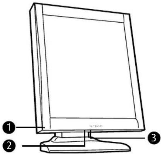
Figure 1: Front side
1 Power LED USB downstream po2
3 Control wheel
Rear view
REAR VIEW OF E-3620, MDNG-5121
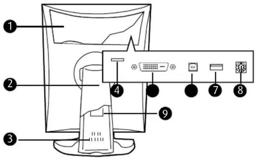
Figure 2: Rear side
1 Connector compartment cover
2 Tilt & swivel foot cover
3 Tilt & swivel foot Slot for securi 4 cable
5 DVI (digital) video input USB up6eam port
7 USB downstream port DC power 8 nput
9 Tilt & swivel foot clip
REAR VIEW OF MDNC-3121, MDNG-2121 AND MDNG-6121
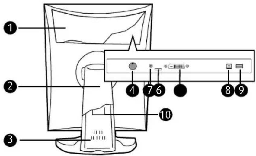
Figure 3: Rear side
1 Connector compartment cover
2 Tilt & swivel foot cover
3 Tilt & swivel foot DC power inp 4
5 +5 Vdc Slot for security cable 6
7 DVI (digital) video input USB up8 team port
9 USB downstream port Tilt & sw101 foot clip
REAR VIEW OF MDNC-2121
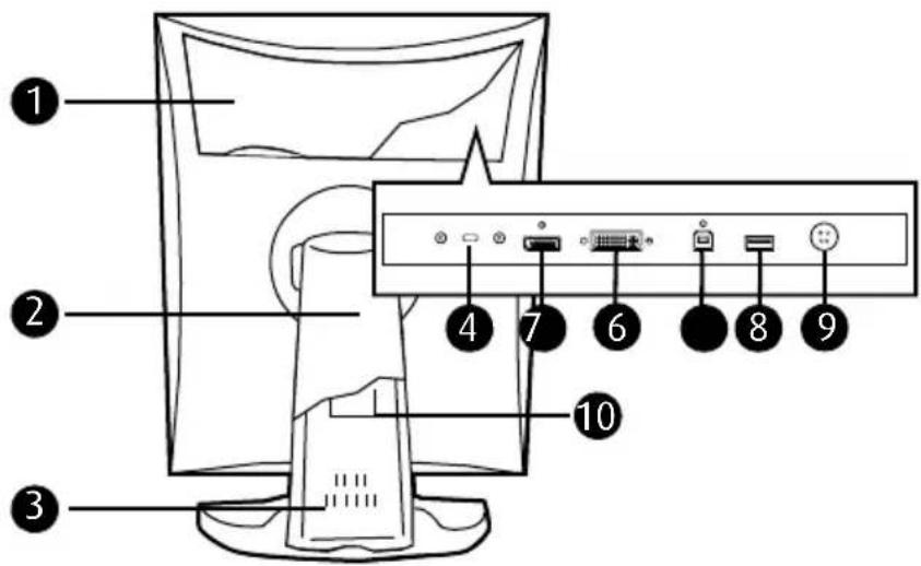
Figure 4: Rear side
1 Connector compartment cover
2 Tilt & swivel foot cover
3 Tilt & swivel foot Slot for securi 4 cable
5 DisplayPort video input DVI (digital) video input
7 USB upstream port USB downs 8 am port
9 DC power input Tilt & swivel fo10clip
Display installation

Prior to installing your BARCO Nio Display and connecting all necessary cables, make sure to have a suitable display controller physically installed in your computer. If you are using a Barco display controller, please consult the dedicated user guide available on the system CD.
Unlocking the height mechanism
In the factory, the height-positioning system in the display foot is blocked with a red clip to prevent damage during transportation. Before installing the display, you must remove this clip.
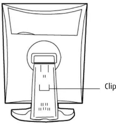
Figure 5: Location of the clip
TO REMOVE THE CLIP:
1 Position the display with its rear side facing you.
2 Pull the red clip out of the fixation holes in the foot.
3 Keep the clip in case the display needs to be shipped later.
Adjusting the display position
You can change the orientation of the panel at any time, but it is more convenient to select landscape or portrait orientation before connecting the cables..
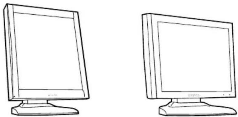
Figure 6: Portrait orientation Figure 7: Landscape orientation
TO CHANGE THE PANEL ORIENTATION
1 Stand at the front side of the panel and take the panel at both sides.
2 Very important: Til the panel before changing the orientation.

Should you change the panel orientation without tilting it first, you might irreversibly damage the tilt & swivel mechanism.
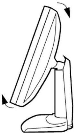
natural_image
Line drawing of a computer monitor with a curved screen and base, showing rotational motion (no text or symbols)Figure 8: Tilt the panel before rotating
3To change from portrait to landscape, turn the panel counterclockwise.
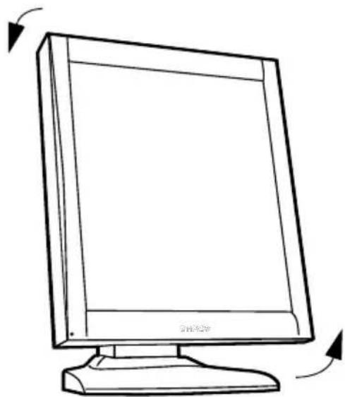
natural_image
Line drawing of a flat-screen computer monitor with two curved arrows indicating rotation (no text or symbols)Figure 9: To rotate the panel from portrait to landscape
4 To change from landscape to portrait, turn clockwise..

If, after installing the display or the system, you change the panel orientation while an image is on the screen, the result depends on the graphic board and the resolution of the image. In some cases the image will be rotated automatically, in other cases it will not be rotated (e.g., when pixels would be lost after rotation). If necessary, change the image resolution in the display control panel and restart the system after changing the orientation.
Connecting the signal cables
TO CONNECT THE SIGNAL CABLES TO THE DISPLAY:
To get access to the connectors, remove the connector compartment cover by pulling down the 2 clips at the top of the cover.
The location of the connectors depends on the display type:
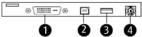
Figure 10: Inputs E-3620, MDNG-5121
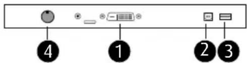
Figure 11: Inputs MDNC-3121, MDNG-2121 and MDNG-6121
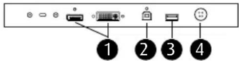
Figure 12: Inputs MDNC-2121
- Connect one end of the DVI/DisplayPort cable to the DVI/DisplayPort input of the display (1). Connect the other end of the DVI/DisplayPort cable to the DVI/DisplayPort connector of the display controller board.
- Connect a PC USB downstream connector to the display's USB upstream connector by means of a USB cable (2).
- Connect any USB device to one of the display's USB downstream connectors (3)
- Connect the DC power input (4) of the display to the external DC power supply. Connect the other end of the external DC power supply to a grounded power outlet by means of the proper power cord delivered in the packaging.
Routing the cables
- Bind the cables in the connector compartment together with the cable tie inside the connector compartment.
- Put the connector compartment cover back on the display. Pay attention that the signal cables are positioned under the bulge in the cover.
- Push the cables into the clips on the rear of the tilt & swivel foot.
- Bind the cables together above and under the foot, by means of the 2 velcro strips attached to the inside of the foot cover (packed inside the accessory box).
• At last, put the foot cover back in place.
Re-attaching the covers
natural_image
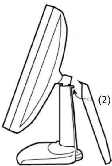
Line drawing of a computer monitor with a handle and base, labeled (2), showing no text or symbols on the device itself.Figure 13: Installing the cover
1The foot cover is packaged separately in the accessory box. Unpack the foot cover.
2Push the upper side of the cover onto the foot, so that the hooks inside the cover are positioned right under the bulges at the rear of the foot.
3Slide the cover upward while moving the lower side of the cover towards the foot.
4Press the cover to the foot so that it makes a clicking sound.
VESA-mount installation
The panel, standard attached to the tilt & swivel foot, is compatible with the VESA 100 mm standard. So it can be used with an arm stand according to the VESA 100 mm standard.
Therefore, the tilt & swivel foot must be removed from the panel..

- Use an arm that is approved by VESA (according to the VESA 100 mm standard).
- Use an arm that can support a weight of at least 13 kg (28.66 lbs).
TO ATTACH THE DISPLAY TO AN ARM STAND:
1 Put the display face down on a clean and soft surface. Be careful not to damage the panel screen.
2Remove the tilt & swivel foot cover.

Never move a display attached to an arm by pulling or pushing the display itself. Instead, make sure that the arm is equipped with a VESA approved handle and use this to move the display.
Please refer to the instruction manual of the arm for more information and instructions.
3 Remove the small screw (A) fixing the small plastic cover on top of the foot. Next, remove the small cover itself.
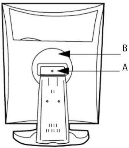
Figure 14: Display with tilt & swivel foot cover removed
4Unscrew the 2 screws fixing the round plastic cover (B).
5 Lift up the round plastic cover.
6Remove the four screws fixing the foot while supporting the foot.
7 Attach the arm stand firmly to the panel using 4 screws M4 x 8 mm.
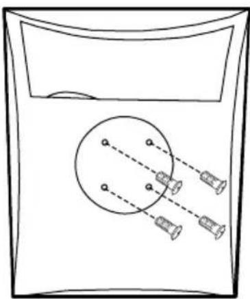
natural_image
Simple line drawing of a container with a circular object and three cylindrical objects inside, no text or symbols present.4 screws M4 x 8mm
Figure 15: Location of the screws
Daily operation
Recommendations for daily operation
OPTIMIZE THE LIFETIME OF YOUR DISPLAY
Enabling the Display Power Management System (DPMS) of your display will optimize its diagnostic lifetime by automatically switching off the backlight when the display is not used for a specified period of time. By default, DPMS is enabled on your display, but it also needs to be activated on your workstation. To do this, go to “Power Options Properties” in the “Control Panel”.

Barco recommends setting DPMS activation after 20 minutes of non-usage.
USE A SCREEN SAVER TO AVOID IMAGE RETENTION
Prolonged operation of an LCD with the same content on the same screen area may result in a form of image retention.
You can avoid or significantly reduce the occurrence of this phenomenon by using a screen saver. You can activate a screen saver in the "Display properties" window of your workstation.

Barco recommends setting screen saver activation after 5 minutes of non-usage. A good screen saver displays moving content.
In case you are working with the same image or an application with static image elements for several hours continuously (so that the screen saver is not activated), change the image content regularly to avoid image retention of the static elements.
UNDERSTAND PIXEL TECHNOLOGY
LCD displays use technology based on pixels. As a normal tolerance in the manufacturing of the LCD, a limited number of these pixels may remain either dark or permanently lit, without affecting the diagnostic
performance of the product. To ensure optimal product quality, Barco applies strict selection criteria for its LCD panels.

To learn more about LCD technology and missing pixels, consult the dedicated white papers available at www.barco.com/healthcare.
ENHANCE USER COMFORT
Every Barco multi-head display system is color matched with the highest specification in the market.

Barco recommends keeping color-matched displays together. Furthermore, it is important to use all displays of a multi-head configuration at the same rate to preserve color matching throughout the economic lifetime of the system.
MAXIMIZE QUALITY ASSURANCE
The 'MediCal QAWeb' system offers online service for high-grade Quality Assurance, providing maximum diagnostic confidence and uptime.

Barco recommends to install MediCal QAWeb Agent and apply the default QAWeb policy at least. This policy includes calibration on regular intervals. Connecting to MediCal QAWeb Server offers even more possibilities. Learn more and sign up for the free MediCal QAWeb Essential level at www.barco.com/healthcare/qa
Stand-by switching

The connected power supply also provides a switch that can be used to turn the power completely off. To use the display, please make sure to switch on this power supply. This can be done by pushing the on/off switch on the power supply into the "|" position.
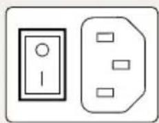
natural_image
Simple line drawing of two electrical socket components (no text or symbols)ON E-3620 AND MDNG-5121 DISPLAYS:
When the display is on and no on-screen display is visible, push and hold the control wheel at the front for a few seconds to switch the display in stand-by. The LED turns orange.
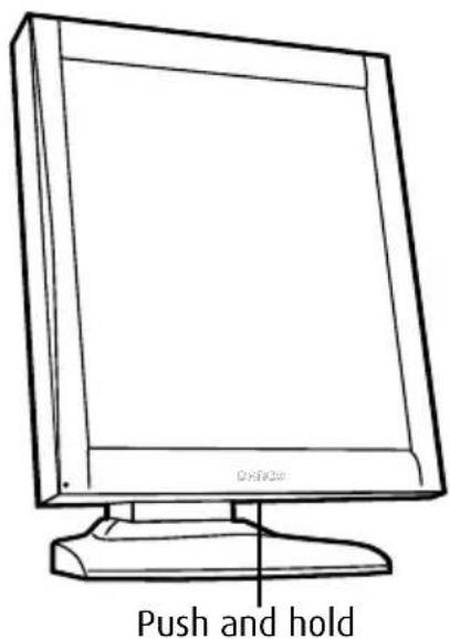
Figure 16: Location of the control wheel
When the display is in stand-by, press the control wheel to switch it back on.
ON MDNC-2121, MDNC-3121, MDNG-2121 AND MDNG-6121 DISPLAYS:
1 When the display is on and no on-screen display is visible, push the control wheel at the front shortly.
2An on-screen message appears, asking to press to confirm.
3Push the control wheel once more to confirm and switch to standby.
4The LED turns orange.
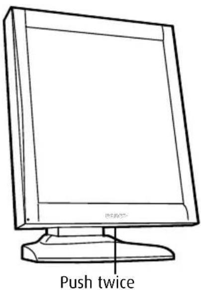
Figure 17: Location of the control wheel
5 When the display is in stand-by, press the control wheel shortly to switch it back on.
Locking and unlocking user controls
The User Controls function allows to disable or enable the control wheel functions. The procedure is slightly different depending on the type of display.
When user controls are disabled, you cannot display and use the on-screen display.
TO DISABLE USER CONTROLS ON E-3620 AND MDNG-5121:
1 Rotate the control wheel to display the on-screen display. The Main Menu appears.
2 Rotate the control wheel to select Settings.
3Press the control wheel to enter the Settings menu.
| SETTINGS | |
| DPMS | On |
| Power LED | On |
| User Controls | On |
| EXIT | |
Figure 18: Settings menu (example)
4 Rotate the control wheel to select User Controls.
5Press the control wheel to switch from "On" to "Off".
6 Exit the menus.
TO DISABLE USER CONTROLS ON MDNC-2121, MDNC-3121, MDNG-2121 AND MDNG-6121:
1 Rotate the control wheel to display the on-screen display. The Main Menu appears.
2 Rotate the control wheel to select Settings.
3 Press the control wheel to enter the Settings menu.
| SETTINGS | |
| DPMS | On |
| Power LED | On |
| User Controls | On |
| EXIT | |
Figure 19: Settings menu (example)
4 Rotate the control wheel to select User Controls.
5Press the control wheel to activate the User Controls function. This is indicated by the scroll bar that becomes longer.
6 Rotate the control wheel to switch from "On" to "Off".
7 Press the control wheel to confirm and return to the Settings menu.
8Exit the menus.
TO ENABLE USER CONTROLS:
1 Make sure the on-screen display is not on the screen.
2Do not use the control wheel for at least 3 seconds.
3 Only for MDNC-2121, MDNC-3121, MDNG-2121 and MDNG-6121: Press and hold the control wheel for at least 5 seconds.
4 Rotate the control wheel 1 step clockwise.
5Press the control wheel 2 times.
6 Rotate the control wheel 1 step counterclockwise.

Steps 4 to 6 must be performed in maximum 3 seconds.
In MDNC-2121, MDNC-3121, MDNG-2121 and MDNG-6121 displays, the user controls are automatically enabled after this procedure. In other Nio displays, you must enable the user controls again in the Settings menu.
Bringing up the OSD menu
When the OSD is not on the screen, rotate the control wheel to display the OSD.
The main menu appears..
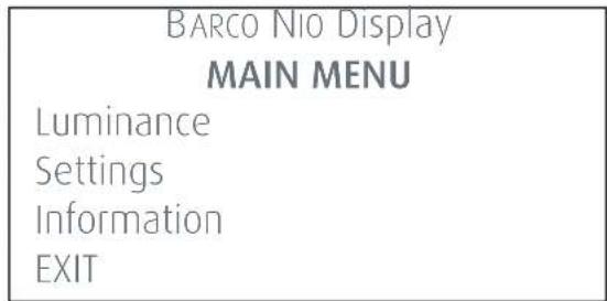
Figure 20: Main menu (example)
Navigating through the OSD menus
1 Rotate the control wheel to move up and down through the menus.
2To go into a submenu, rotate the control wheel to highlight the submenu. Next, press the control wheel to go into the submenu.
3 When you press on Exit, the OSD exits the submenu and jumps to the previous (higher-level) menu. When you press on Exit in the main menu, the OSD is hidden.
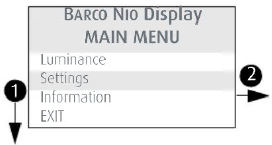
| SETTINGS | |
| DPMS | On |
| Power LED | On |
| User controls | On |
| EXIT | |
1 Rotate the control wheel
2Press the control wheel
Figure 21: OSD menu navigation
Making selections in the OSD menus
1 Navigate through the menus and highlight the parameter you wish to select.
2Press the control wheel to make a selection or to toggle between several settings.
Changing values in the OSD menus
1 Navigate through the menus and highlight the parameter you wish to adjust.
2Press the control wheel to go into edit mode.
3 Rotate the wheel to change the value.
4Press the wheel to enter the new value and return to the menu.
Advanced operation
On-screen display (OSD)
Input Selection menu\*
| Auto Detects the incoming video signal automatically and displays it on the screen. |
| DVI Always displays the DVI signal on the screen. When no DVI signal available, there will be no image on the screen. |
| DP Always displays the DisplayPort signal on the screen. When no DP signal available, there will be no image on the screen. |
* Only in MDNC-2121 displays
Luminance and color menu

In grayscale Nio displays this menu is called "Luminance".
| Measured luminance** | Indicates the actual luminance measured by the internal sensor. This is a read-only value. It is expressed in a percentage of the calibrated value (100% is calibrated). |
| Luminance target Allows to manually adjust the luminance target. See note below. | |
| Color target* Allows to select from a list of factory-defined and user-defined color targets. You can select from a range of standard Daylight (D) color temperatures, Clearbase, Bluebase and Native.The higher the D-number, the more bluish the color temperature is.'Native' is the uncorrected color temperature of the LCD panel. | |
| Viewing mode** Allows to select a pre-defined viewing mode. Diagnostic is the standard mode for viewing medical images. In Text mode the calibrated luminance is decreased so the viewing conditions are optimal for viewing office documents (text documents, spreadsheets etc.) | |
* Only in MDNC-2121 and MDNC-3121 displays.
** Only in MDNC-2121, MDNC-3121, MDNG-2121 and MDNG-6121 displays

When you change the luminance target, the display will adjust its backlight to reach the target. This can be seen in the Measured luminance line.
When the luminance target cannot be reached, e.g., due to aging of the backlight, the Measured luminance line changes to Minimum value reached or Maximum value reached.
Display Function menu\*
| Display function Allows to select from a list of pre-defined display functions.If the DICOM DF is selected, an additional function is available. |
| ALC & DICOM options Jumps to the ALC & DICOM Options submenu, which allows to edit the settings for the DICOM display function.This function is available only when the DICOM DF is selected. |
*This menu is available only in MDNC-2121, MDNC-3121, MDNG-2121 and MDNG-6121.
ALC & DICOM OPTIONS SUBMENU\*
| Correction value Shows the ambient light correction value that is taken into account in the calculation of the display function, measured in lux. | |
| DICOM offset The DICOM DF is recalculated at the moment the DICOM Offset is changed, taking the new DICOM Offset into account.When set to “Dark Room”, the ambient light is not taken into account.When set to “Preset”, a preset ambient light value determined by the selected reading room is taken into account. | |
| Reading room Allows to select from a pre-defined list of reading room types.You must select a reading room that corresponds to the type of room the display is installed in. | |
| Reading room def. Jumps to the reading room definition submenu, which allows to edit the reading room condition settings. | |
| Calibration info Jumps to the calculation information submenu, which displays information about the values taken into account to recalculate the DICOM DF. |
*This menu is available only in MDNC-2121, MDNC-3121, MDNG-2121 and MDNG-6121.
READING ROOM DEFINITION SUBMENU\*
| Reading room Indicates the reading room type you are editing. You can select another room to edit by rotating the control wheel. |
| Max. ambient light This indicates the maximum ambient light that corresponds to the selected reading room.If the measured ambient light is higher than the value entered here, you should take measures to darken the room or select another reading room type. |
| Preset corr. value This value is taken into account in the calculation of the DICOM DF if DICOM Offset is set to “Preset”.To each reading room type corresponds another preset value. |
*This menu is available only in MDNC-2121, MDNC-3121, MDNG-2121 and MDNG-6121.
CALIBRATION INFORMATION SUBMENU\*
| (Preset) Ambient value | Shows the ambient light correction value taken into account to calculate the DICOM DF, expressed in lux. |
| Bright luminance Shows the bright luminance value taken into account to calculate the DICOM DF. | |
| Dark luminance Shows the dark luminance value taken into account to calculate the DICOM DF. | |
| Ambient correction Shows the ambient light correction value taken into account to calculate the DICOM DF, expressed in cd/m2. | |
*This menu is available only in MDNC-2121, MDNC-3121, MDNG-2121 and MDNG-6121.
Settings menu
| DPMS Allows to switch the display power management system on/off. See note below. | |
| Power LED Allows to switch the power LED's on state on/off. The LED's orange DPMS state is not influenced by this setting. So, when the display goes into power-saving mode, the LED will turn orange, even if it was switched off by this setting | |
| User controls Allows to disable the control wheel on the front.When switched off, the user cannot display the OSD unit the user controls are enabled again. For more information, Locking and unlocking user controls, on page 23. | |
| Language* Allows to select another language for the OSD menus. | |
| Auto menu exit* Allows to switch the automatic menu exit on/off. When switched on, the OSD is closed automatically when left idle for a certain time. | |
| Preferred Input Select the video resolution you wish the connected graphic board(s) to reproduce. After changing this setting you must reboot the PC.This function takes effect with plug-and-play graphic boards only.In some displays, there is only 1 setting for this function. |
*Only in MDNC-2121, MDNC-3121, MDNG-2121 and MDNG-6121.

The DPMS system will power down the display when the connected computer is left idle for a certain time.

Barco recommends to switch DPMS on and to use a good Windows screen saver to prevent image burn-in (image retention) on the LCD panel.
Information menu
| Product The display type | |
| Serial No Indicates the display serial number | |
| SW Version Displays the current internal software version | |
| Display Runtime* Indicates the total time the display has been operating, including the time in stand-by | |
| Backlight Runtime* Indicates the total time the display has been operating, excluding the time in stand-by |
In some NIO displays these functions are called “Display Lifetime” and “Backlight Lifetime”. Their function, however, is the same as described in the table above.
Changing Display Functions
Concepts

Display function selection is possible only in MDNC-3121, MDNG-2121 and MDNG-6121 displays.
•The Display Function menu lets you select a display function (DF).
- When you select the DICOM DF you can define the DICOM DF to be recalculated taking the ambient light into account.
- In this case, the recalculation can be based on an illuminance of 0 lux ("Dark Room") or a preset value ("Preset") determined by the selected reading room.
- In the latter case you must select a reading room that corresponds to the type of room the display is installed in. E.g. if the display is installed in a room where CT scans are observed, the "CT/MR/NM" reading room is the preferred selection.
•The reading room is defined by 2 parameters:
•Maximum Ambient Light defines the maximum light allowed in this type of room. This value can be adjusted within certain limits determined by the selected reading room.
- Preset Correction Value is the predefined correction value for this reading room. This value can be adjusted within certain limits determined by the selected reading room.
•The reading room parameters are pre-defined in the display according to the AAPM (American Association of Physicists in Medicine). However they can be changed within certain limits.
Display function selection
To select a DISPLAY FUNCTION (DF):
1 When there is no OSD on the screen, rotate the control wheel to display the OSD. The main menu appears.
2 Rotate the control wheel to select the Display Function menu. Press the control wheel shortly to enter the menu.
3 Rotate the control wheel to select Display Function. Press the control wheel shortly to go into edit mode.
4 Rotate the control wheel to select the desired DF.
5 Press the control wheel shortly to activate the new selection.
You can select the following DFs:
| DICOM Select a DICOM display function for most medical viewing applications.The DICOM function results in more visible grayscales in the images. | |
| Dynamic Gamma 2.2 Dynamic Gamma 1.8 | These are gamma functions that are shifted to take into account the non-zero luminance of an LCD panel when driven with a “black” signal.They are especially useful in CT applications to improve the perception of low Haunsfield values. |
| Native If you select Native, the native panel behavior will not be corrected. | |
| Test This is identical to the Native DF. | |
| Gamma 2.2 Gamma 1.8 | Select one of these display functions in case the display is to replace a CRT display with a gamma of 1.8 or 2.2 respectively. |
ALC & DICOM Options
DICOM offset
INTRODUCTION
The DICOM DF will be recalculated only when another DICOM Offset is selected. The DICOM DF will be recalculated based on the new offset setting.
To Select a DICOM OFFSET:
1 Select the DICOM display function. See To select a display function (DF):, on page 36.
2Enter the ALC & DICOM submenu.
3In the ALC & DICOM Options submenu, rotate the control wheel to select DICOM Offset. Press the control wheel shortly to go into edit mode.
4 Rotate the control wheel to select an offset.
5 Press the control wheel shortly to activate the selection.
YOU CAN SELECT THE FOLLOWING OFFSETS:
| Dark room The DICOM DF will be recalculated taking an ambient light value of 0 lux into account.This means that the measured ambient light does not influence the DICOM DF. |
| Preset The DICOM DF will be recalculated taking a preset ambient light value into account. This value is determined by the selected Reading Room and can be adjusted manually within certain limits. |
Reading room selection
This function is available only when the DICOM display function is selected.
TO SELECT A READING ROOM SETTING:
1 Select the DICOM display function. See To select a display function (DF):, on page 36.
2Enter the ALC & DICOM Options submenu.
3In the ALC & DICOM Options submenu, rotate the control wheel to select Reading Room. Press the control wheel shortly to go into edit mode.
4 Rotate the control wheel to select the reading room that corresponds to the room type the display is installed in. Return to the menu.
5You can select the following reading room types:
| CR/DR/MAMMO Corresponds to light conditions in diagnostic reading rooms for computed radiology, digital radiology or mammography. This setting has the lowest maximum ambient light. |
| CT/MR/NM Corresponds to light conditions in diagnostic reading rooms for computed tomography, magnetic resonance or nuclear medicine scans. |
| Office Corresponds to light conditions in office rooms. |
| Clinical Corresponds to light conditions in diagnostic reading rooms for clinical viewing. |
| Emergency Corresponds to light conditions in emergency rooms. |
| Operating Corresponds to light conditions in operating rooms. This setting has the highest maximum ambient light. |
Reading room definition
This function is available only when the DICOM display function is selected.
TO MODIFY A READING ROOM DEFINITION:
1 Select the DICOM display function. See To select a display function (DF):, on page 36.
2Enter the ALC & DICOM Options submenu.
3In the ALC & DICOM Options submenu, rotate the control wheel to select Reading Room Def. Press the control wheel shortly to open the submenu.
4Select the reading room definition you wish to modify. Thereto, rotate the control wheel to select Reading Room. Press the control wheel shortly to go into edit mode. Rotate the control wheel to select the reading room. Press the control wheel shortly to confirm the selection.
5 To modify the maximum ambient light for this reading room, rotate the control wheel to select Max. Ambient Light. Press the control wheel shortly to go into edit mode. Rotate the control wheel to change the value. Press the control wheel shortly to save the changes.
You can change this value within certain limits determined by the selected reading room.
6 To modify the Preset correction value for this reading room, rotat e the control wheel to select Preset Corr. Value. Press the control wheel shortly to go into edit mode. Rotate the control wheel to change the value. Press the control wheel shortly to savethe changes.
You can change this value within certain limits determined by the selected reading room.
Switching DPMS on/off
To switch DPMS ON/OFF:
1 When there is no OSD on the screen, rotate the control wheel. The main OSD menu appears.
2 Rotate the control wheel to select the Settings menu. Press the control wheel shortly to open the menu.
3 Rotate the control wheel to select DPMS.
4For E-3620 and MDNG-5121: Press the control wheel to change the DPMS setting.
For MDNC-3121, MDNG-2121 and MDNG-6121:
Press the control wheel shortly to go into edit mode. Next, rotate the control wheel to change the setting. At last press the control wheel again to save the changes.
Cleaning your display
Front glass
Clean the front glass using a sponge, cleaning cloth or soft tissue, lightly moistened with one of the following tested products:
- Flux - Pril
- Windex Glass Plus
- Ajax glass cleaner
• Bohle glass cleaner • Sidolin glass cleaner
Mr. Proper
• 25% ethanol solution (EtOH)
In case none of the above cleaning products is available, use plain water.

Take care not to damage or scratch the front glass. Be careful with rings or other jewelry and do not apply excessive pressure on the front glass.

Do not apply or spray liquid directly to the front glass as excess liquid may cause damage to internal electronics. Instead, apply the liquid to the cleaning cloth.

Do not use following products:
• Alcohol/solvents at higher concentration > 5%
•Strong alkalis lye, strong solvents
•Acid
• Detergents with fluoride
• Detergents with ammonia
• Detergents with abrasives
- Steel wool
- Sponge with abrasives
- Steel blades
- Cloth with steel thread
Cabinet
1 Clean the cabinet using a soft cotton cloth, lightly moistened with a recognized cleaning product for medical equipment.
The cabinet has been tested for resistance to the following products:
•Cidex, Betadine
•Alcohol (Isopropyl and Ethyl)
•Ammonia-based cleaners (Windex)
•Aquasonic Gel
In case none of the above cleaning products is available, use plain water.

Do not apply or spray liquid directly to the cabinet as excess liquid may cause damage to internal electronics. Instead, apply the liquid to the cleaning cloth.
2 Repeat with water only.
3 Wipe dry with a dry cloth.
Important information
Safety information
GENERAL RECOMMENDATIONS
Read the safety and operating instructions before operating the equipment.
Retain safety and operating instructions for future reference.
Adhere to all warnings on the equipment and in the operating instructions manual.
Follow all instructions for operation and use.
ELECTRICAL SHOCK
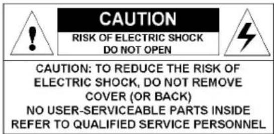
TYPE OF PROTECTION (ELECTRICAL):
Equipment with external power supply: Class I equipment
DEGREE OF SAFETY (FLAMMABLE ANESTHETIC MIXTURE):
Equipment not suitable for use in the presence of a flammable anesthetic mixture with air or with oxygen or nitrous oxide.
NON-PATIENT CARE EQUIPMENT
Equipment primarily for use in a health care facility that is intended for use where contact with a patient is unlikely.
POWER CONNECTION - EQUIPMENT WITH EXTERNAL 12 VDC POWER SUPPLY
- Power requirements: The equipment must be powered using the delivered medical approved 12 VDC power supply.
- The medical approved DC power supply must be powered by the AC mains voltage (protective earth terminal).
POWER CONNECTION - EQUIPMENT WITH EXTERNAL 24 VDC POWER SUPPLY
- Power requirements: The equipment must be powered using the delivered medical approved 24 VDC SELV power supply.
•The medical approved DC power supply must be powered by the AC mains voltage (protective earth terminal).
TRANSIENT OVER-VOLTAGE
If the equipment is not used for a long time, disconnect it from the AC inlet to avoid damage by transient over-voltage.
To fully disengage the power to the unit, please disconnect the power cord from the AC inlet.
POWER CORDS:
- Utilize a UL-listed detachable power cord, 3-wire, type SJ or equivalent, 18 AWG min., rated 300 V min., provided with a hospital-grade type plug 5-15P configuration for 120V application, or 6-15P for 240V application.
- Do not overload wall outlets and extension cords as this may result in fire or electric shock.
- Mains lead protection (U.S.: Power cord): Power cords should be routed so that they are not likely to be walked upon or pinched by items placed upon or against them, paying particular attention to cords at plugs and receptacles.
WATER AND MOISTURE
Never expose the equipment to rain or moisture.
Never use the equipment near water - e.g. near a bathtub, washbasin, swimming pool, kitchen sink, laundry tub or in a wet basement.
VENTILATION
Do not cover or block the ventilation openings in the cover of the set. When installing the equipment in a cupboard or another closed location, heed the necessary space between the set and the sides of the cupboard.
INSTALLATION
Place the equipment on a flat, solid and stable surface that can support the weight of at least 3 equipments. If you use an unstable cart or stand, the equipment may fall, causing serious injury to a child or adult, and serious damage to the equipment.
THIS APPARATUS CONFORMS TO:
CE0120 (MDD 93/42/EEC class IIb product), IEC 60601-1, UL 60601-1, CAN/CSA C22.2 No. 601.01-M90 (c-UL), CCC GB4943-1995 (IEC 60950-1), IEC 60601-1:2005, EN 60601-1-2:2006, ANSI/AAMI ES 60601-1:2005, CAN/CSA-C22.2 No. 60601-1-08.
MDNC-2121: Medical equipment with respect to electric shock, fire and mechanical hazards only in accordance with UL 60601-1. and CAN/CSA C22.2 NO. 601.1.
NATIONAL SCANDINAVIAN DEVIATIONS FOR CL. 1.7.2:
Environmental information
DISPOSAL INFORMATION (WASTE ELECTRICAL AND ELECTRONIC EQUIPMENT)

This symbol on the product indicates that, under European Directive 2002/96/EC governing waste from electrical and electronic equipment, this product must not be disposed of with other municipal waste. Please dispose of your waste equipment by handing it over to a designated collection point for the recycling of waste electrical and electronic equipment. To prevent possible harm to the environment or human health from uncontrolled waste disposal, please separate these items from other types of waste and recycle them responsibly to promote the sustainable reuse of material resources.
For more information about recycling of this product, please contact your local city office, your municipal waste disposal service or the shop where you purchased the product.
MERCURY NOTICE
This Barco product consists of materials that may contain mercury, which must be recycled or disposed of in accordance with local, state, or country laws:
- Within this system, the backlight lamps in the monitor display contain mercury

LAMP CONTAINS MERCURY, DISPOSE ACCORDING TO STATE/LOCAL LAW. 灯泡含水银,请按当地法律处理。
TURKEY ROHS COMPLIANCE

According to the "China Administration on Control of Pollution Caused by Electronic Information Products" (Also called RoHS of Chinese Mainland), the table below lists the names and contents of toxic and/or hazardous substances that Barco's product may contain. The RoHS of Chinese Mainland is included in the MCV standard of the Ministry of Information Industry of China, in the section "Limit Requirements of toxic substances in Electronic Information Products".
| 零件项目(名称)Component Name | 有毒有害物质或元素Hazardous Substances or Elements | |||||
| 铅(Pb) | 汞(Hg) | 镉(Cd) | 六价铬(Cr6+) | 多溴联苯(PBB) | 多溴二苯醚(PBDE) | |
| 印制电路配件Printed CircuitAssemblies | X | O | O | O | O | |
| 液晶面板LCD panel | X | X | O | O | O | |
| 外接电(线)缆External cables | X | O | O | O | O | |
| 内部线路Internal wiring | O | O | O | O | O | |
| 金属外壳Metal enclosure | O | O | O | O | O | |
| 塑胶外壳Plastic enclosure | O | O | O | O | O | |
| 散热片(器)Heatsinks | O | O | O | O | O | |
| 风扇Fan | O | O | O | O | O | |
| 电源供应器Power supply unit | X | O | O | O | O | |
| 文件说明书Paper manuals | O | O | O | O | O | |
| 光盘说明书CD manual | O | O | O | O | O | |
| O:表示该有毒有害物质在该部件所有均质材料中的含量均在SJ/T 11363-2006标准规定的限量要求以下。O:Indicates that this toxic or hazardous substance contained in all of the homogeneous materials for this part is below the limit requirement in SJ/T11363-2006.X:表示该有毒有害物质至少在该部件的某一均质材料中的含量超出SJ/T 11363-2006标准规定的限量要求。X:Indicates that this toxic or hazardous substance contained in at least one of the homogeneous materials used for this part is above the limit requirement in SJ/T11363 2006. | ||||||
All Electronic Information Products (EIP) that are sold within Chinese Mainland must comply with the "Electronic Information Products Pollution Control Labeling Standard" of Chinese Mainland, marked with the Environmental Friendly Use Period (EFUP) logo. The number inside the EFUP logo that Barco uses (please refer to the photo) is based on the "Standard of Electronic Information Products Environmental Friendly Use Period" of Chinese Mainland.

Regulatory compliance information
INDICATIONS FOR USE: E-3620, MDNG-2121, MDNC-3121, MDNC-2121
The products are intended to be used in displaying and viewing digital images, for review and analysis by trained medical practitioners. These devices must not be used in primary image diagnosis in mammography.
Caution (USA): Federal law restricts this device to sale by or no the order of a physician or a practitioner trained on its use.
INDICATIONS FOR USE: MDNG-5121, MDNG-6121
The products are intended to be used in displaying and viewing digital images, including digital mammography, for review and analysis by trained medical practitioners.
Caution (USA): Federal law restricts this device to sale by or no the order of a physician or a practitioner trained on its use.
FCC CLASS B
This device complies with Part 15 of the FCC Rules. Operation is subject to the following two conditions: (1) this device may not cause harmful interference, and (2) this device must accept any interference received, including interference that may cause undesired operation.
This equipment has been tested and found to comply with the limits for a Class B digital device, pursuant to Part 15 of the FCC Rules. These limits are designed to provide reasonable protection against harmful interference in a residential installation. This equipment generates, uses and can radiate radio frequency energy and, if not installed and used in accordance with the instructions, may cause harmful interference to radio communications. However, there is no guarantee that interference will not occur in a particular installation. If this equipment does cause harmful interference to radio or television reception, which can be determined by turning the equipment off and on, the user is encouraged to try to correct the interference by one or more of the following measures:
•Reorient or relocate the receiving antenna.
- Increase the separation between the equipment and receiver.
- Connect the equipment into an outlet on a circuit different from that to which the receiver is connected.
- Consult the dealer or an experienced radio/TV technician for help.
CANADIAN NOTICE
This ISM device complies with Canadian ICES-001.
This device complies with appropriate medical EMC standards on emissions to, and interference from surrounding equipment. Operation is subject to the following two conditions: (1) this device may not cause harmful interference, and (2) this device must accept any interference received, including interference that may cause undesired operation.
Interference can be determined by turning the equipment off and on.
If this equipment does cause harmful interference to, or suffer from harmful interference of, surrounding equipment, the user is encouraged to try to correct the interference by one or more of the following measures:
•Reorient or relocate the receiving antenna or equipment.
- Increase the separation between the equipment and receiver.
- Connect the equipment into an outlet on a circuit different from that to which the receiver is connected.
- Consult the dealer or an experienced technician for help.
Explanation of symbols
On the display or power supply, you may find the following symbols (nonrestrictive list):
 | Indicates compliance to the essential requirements of the Directive 93/42/EEC |
 | Indicates compliance with Part 15 of the FCC rules (Class A or Class B) |
  or or | Indicates the display is approved according to the UL regulations |
  or or | Indicates the display is approved according to the c-UL regulations |
 | Indicates the display is approved according to the DEMKO regulations |
 | Indicates the display is approved according to the CCC regulations |
 | Indicates the display is approved according to the VCCI regulations |
 | Indicates the USB connectors on the display |
 | Indicates the manufacturing date |
 | Indicates the temperature limitations for the display to operate within specs |
 | Indicates the display serial no. |
 | Consult the operating instructions |
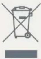 | Indicates this apparatus must not be thrown in the trash but must be recycled, according to the European WEEE (Waste Electrical and Electronic Equipment) directive |
Legal disclaimer
DISCLAIMER NOTICE
Although every attempt has been made to achieve technical accuracy in this document, we assume no responsibility for errors that may be found. Our goal is to provide you with the most accurate and usable documentation possible; if you discover errors, please let us know.
Barco software products are the property of Barco. They are distributed under copyright by Barco N.V. or Barco, Inc., for use only under the specific terms of a software license agreement between Barco N.V. or Barco Inc. and the licensee. No other use, duplication, or disclosure of a Barco software product, in any form, is authorized.
The specifications of Barco products are subject to change without notice.
TRADEMARKS
All trademarks and registered trademarks are property of their respective owners.
COPYRIGHT NOTICE
This document is copyrighted. All rights are reserved. Neither this document, nor any part of it, may be reproduced or copied in any form or by any means - graphical, electronic, or mechanical including photocopying, taping or information storage and retrieval systems - without written permission of Barco.
© 2012 Barco N.V. All rights reserved.
Technical specifications
Nio 2MP
| Product acronym MDNG-2121 | |
| Screen technology TFT AM LCD Dual Domain IPS | |
| Active screen size (diagonal) | 540 mm (21.3") |
| Active screen size (H x V) 432 x 324 mm (17.0 x 12.8") | |
| Aspect ratio (H:V) 4:3 | |
| Resolution 2MP (1600 x 1200) | |
| Pixel pitch 0.2700 mm | |
| Color imaging No | |
| Gray imaging Yes | |
| Number of grayscales (LUT in/LUT out) | 1024 grey levels (10/12) |
| Viewing angle (H, V) 170° | |
| Uniform Luminance Technology (ULT) | Yes |
| Per Pixel Uniformity (PPU) No | |
| Ambient Light Compensation (ALC) | No |
| Backlight Output Stabilization (BLOS) | Yes |
| I-Guard No | |
| Maximum luminance* 1650 cd/m2 | |
| DICOM calibrated luminance (ULT off)* | 500 cd/m2 |
| Contrast ratio (typical)* 850:1 | |
| Response time (Tr + Tf) 23 ms | |
| Scanning frequency (H; V) 15-129 kHz; 24-100 Hz | |
| Housing color Gray | |
| Video input signals DVI-D Dual Link | |
| USB ports 1 upstream (endpoint), 2 downstream | |
| USB standard 2.0 | |
| Power requirements(nominal) | 100-240V |
| Power consumption(nominal) | 65W |
| Power save mode Yes | |
| Power management DVI-DMPM | |
| Dot clock 280 MHz | |
| OSD languages English, French, German, Spanish, Italian | |
| Dimensions with stand (W x H x D) | Portrait: 385 x 525~585 x 250 mmLandscape: 485 x 475~535 x 250 mm |
| Dimensions w/o stand (W x H x D) | Portrait: 385 x 485 x 115 mmLandscape: 485 x 385 x 115 mm |
| Dimensions packaged (W x H x D) | 500 x 675 x 320 mm |
| Net weight with stand 12.2 kg | |
| Net weight w/o stand 8.14 kg | |
| Net weight packaged with stand | 17.19 kg |
| Net weight packaged w/o stand | 13.15 kg |
| Height adjustment range 60 mm | |
| TiltSwivel -45° / +45° | -5° / +30° |
| Pivot 90° | |
| Mounting standard VESA (100 mm) | |
| Screen protection Protective, non-reflective PMMA cover | |
| Recommended modalities CT, MR, US, DR, CR, NM, Film | |
| Certifications BSMI, CCC - GB4943-2001 - GB9254-1998 - GB9254-2008 - GB17625.1-2003, DEMKO EN60601-1:1990 + A1:1993 + A2:1995, IEC 60601-1:1998 + A1:91 + A2:95, UL 60601-1 1st edition, CAN/CSA-CS22.2 No.601.1-M90, FDA510K, RoHs, MDD, WEEE,CE 0120, VCCI, FCC Class B, KETI, IEC 60601-1:2005, EN 60601-1-2:2006, ANSI/AAMI ES 60601-1:2005, CAN/CSA-C22.2 No. 60601-1-08. | |
| Supplied accessories User Guide | |
| Optional accessories NA | |
| QA software MediCal QAWeb | |
| Unit per pallet NA | |
| Pallet dimensions NA | |
| Warranty | 5 years |
| Operating temperature | 0°C to 35°C (15°C to 35°C within specs) |
| Storage temperature | -20°C to 60°C |
| Operating humidity | 8% - 80% (non-condensing) |
| Storage humidity | 5% - 95% (non-condensing) |
| Operating altitude | 3000 m |
| Storage altitude | 7500 m |
* In dark reading room conditions (0 lux)
Nio 3MP
| Product acronym E-3620 (MA) | |
| Screen technology TFT AM LCD Dual Domain IPS | |
| Active screen size (diagonal) | 528 mm (20.8") |
| Active screen size (H x V) 424 x 318 mm (16.7 x 12.5") | |
| Aspect ratio (H:V) 4:3 | |
| Resolution 3MP (2048 x 1536) | |
| Pixel pitch 0.207 mm | |
| Color imaging No | |
| Gray imaging Yes | |
| Number of grayscales (LUT in/LUT out) | 1024 grey levels (10/10) |
| Viewing angle (H, V) 170° | |
| Uniform Luminance Technology (ULT) | Yes |
| Per Pixel Uniformity (PPU) No | |
| Ambient Light Compensation (ALC) | No |
| Backlight Output Stabilization (BLOS) | Yes |
| I-Guard No | |
| Maximum luminance* 1000 cd/m2 | |
| DICOM calibrated luminance (ULT off)* | 500 cd/m2 |
| Contrast ratio (typical)* | 900:1 |
| Response time (Tr + Tf) | 50 ms |
| Scanning frequency (H; V) | 30-124 kHz; 50-85 Hz |
| Housing color Gray | |
| Video input signals DVI-D Dual Link | |
| USB ports 1 upstream, 2 downstream | |
| USB standard 1.1 | |
| Power requirements (nominal) | 100-240V |
| Power consumption (nominal) | 54W |
| Power save mode Yes | |
| Power management DVI-DMPM | |
| Dot clock 280 MHz | |
| OSD languages English | |
| Dimensions with stand (W x H x D) | Portrait: 385 x 525~585 x 250 mmLandscape: 485 x 475~535 x 250 mm |
| Dimensions w/o stand (W x H x D) | Portrait: 385 x 485 x 115 mmLandscape: 485 x 385 x 115 mm |
| Dimensions packaged (W x H x D) | 500 x 675 x 320 mm |
| Net weight with stand 13 kg | |
| Net weight w/o stand 9 kg | |
| Net weight packaged with stand | 15 kg |
| Net weight packaged w/o stand | 11 kg |
| Height adjustment range 60 mm | |
| Tilt -5° / +30° | |
| Swivel -45° / +45° | |
| Pivot | 90° |
| Mounting standard VESA (100 mm) | |
| Screen protection Protective, non-reflective PMMA cover | |
| Recommended modalities CT, MR, US, DR, CR, NM, Film | |
| Certifications CCC - GB4943-2001 - GB9254-1998 (Class A) -GB9254-2008 (Class A) - GB17625.1-2003, DEMKOEN60601-1:1990 + A1:1993 + A2:1995 + A11: 1993 +A12: 1993 + A13:1996, IEC 60601-1:1988 + A1:1991 +A2:1995 2nd edition, UL 60601-1 1st edition 2006-04-26, CAN/CSA-C22.2 No.601.1-M90 2005, FDA510K,RoHs, MDD, WEEE, CE 0120, VCCI, FCC Class B, KETI, IEC60601-1:2005, EN 60601-1-2:2006, ANSI/AAMI ES60601-1:2005, CAN/CSA-C22.2 No. 60601-1-08 | |
| Supplied accessories User Guide | |
| Quick-Installation SheetVideo cable (DVI Dual Link)Mains cables (UK, European (CEBEC/KEMA), USA (UL/CSA; adaptor plug NEMA 5-15P), Chinese (CCC))External power supply | |
| Optional accessories NA | |
| QA software MediCal QAWeb | |
| Unit per pallet NA | |
| Pallet dimensions NA | |
| Warranty 5 years | |
| Operating temperature | 0°C to 40°C (15°C to 35°C within specs) |
| Storage temperature | -20°C to 60°C |
| Operating humidity | 8% - 80% (non-condensing) |
| Storage humidity | 5% - 95% (non-condensing) |
| Operating altitude | 3000 m |
| Storage altitude | 7500 m |
* In dark reading room conditions (0 lux)
Nio 5MP
| Product acronym MDNG-5121 | |
| Screen technology TFT AM LCD Dual Domain IPS | |
| Active screen size (diagonal) | 541 mm (21.3") |
| Active screen size (H x V) 422 x 338 mm (16.5 x 13.3") | |
| Aspect ratio (H:V) 5:4 | |
| Resolution 5MP (2560 x 2048) | |
| Pixel pitch 0.165 mm | |
| Color imaging No | |
| Gray imaging Yes | |
| Number of grayscales (LUT in/LUT out) | 10 bit/10 bit |
| Viewing angle (H, V) 170° | |
| Uniform Luminance Technology (ULT) | No |
| Per Pixel Uniformity (PPU) No | |
| Ambient Light Compensation (ALC) | No |
| Backlight Output Stabilization (BLOS) | Yes |
| I-Guard No | |
| Maximum luminance* 700 cd/m2 | |
| DICOM calibrated luminance (ULT off)* | 500 cd/m2 |
| Contrast ratio (typical)* 800:1 | |
| Response time (Tr + Tf) 50 ms | |
| Scanning frequency (H; V) | 30-124 kHz; 45-85 Hz |
| Housing color Gray | |
| Video input signals DVI-D Dual Link | |
| USB ports 1 upstream (endpoint), 2 downstream | |
| USB standard 1.1 | |
| Power requirements(nominal) | 100-250V |
| Power consumption(nominal) | 61W |
| Power save mode Yes | |
| Power management DVI-DMPM | |
| Dot clock 330 MHz | |
| OSD languages English | |
| Dimensions with stand (W x H x D) | Portrait: 408 x 489~549 x 250 mmLandscape: 492 x 531~591 x 250 mm |
| Dimensions w/o stand (W x H x D) | Portrait: 408 x 492 x 115 mmLandscape: 492 x 408 x 115 mm |
| Dimensions packaged (W x H x D) | 500 x 320 x 675 mm |
| Net weight with stand 12.5 kg | |
| Net weight w/o stand 8.5 kg | |
| Net weight packaged with stand | 15.2 kg |
| Net weight packaged w/o stand | NA |
| Height adjustment range 60 mm | |
| Tilt -5° / +30° | |
| Swivel -45° / +45° | |
| Pivot | 90° |
| Mounting standard VESA (100 mm) | |
| Screen protection Protective, non-reflective PMMA cover | |
| Recommended modalities CT, MR, US, DR, CR, NM, Film | |
| Certifications BSMI, CCC - GB4943-2001 - GB9254-1998 (Class A) -GB9254-2008 (Class A) - GB17625.1-2003, DEMKOEN60601-1:1990 + A1:1993 + A2:1995, IEC 60601-1:1998 + A1:1991 + A2:1995 2nd edition, IEC 60601-1(ed.2) am1 & am2, UL 60601-1 1st edition 2006-04-26, CAN/CSA-C22.2 No.601.1-M90 2005, FDA510K,RoHs, MDD, WEEE, CE 0120, VCCI, FCC Class B, KETI, IEC60601-1:2005, EN 60601-1-2:2006, ANSI/AAMI ES60601-1:2005, CAN/CSA-C22.2 No. 60601-1-08 | |
| Supplied accessories User Guide | |
| Quick-Installation SheetVideo cable (DVI Dual Link)Mains cables (UK, European (CEBEC/KEMA), USA (UL/CSA; adaptor plug NEMA 5-15P), Chinese (CCC))USB 2.0 cableExternal power supply | |
| Optional accessories NA | |
| QA software MediCal QAWeb | |
| Unit per pallet NA | |
| Pallet dimensions NA | |
| Warranty 5 years | |
| Operating temperature 0°C to 40°C (15°C to 35°C within specs) | |
| Storage temperature | -20°C to 60°C |
| Operating humidity | 8% - 80% (non-condensing) |
| Storage humidity | 5% - 95% (non-condensing) |
| Operating altitude | 3000 m |
| Storage altitude | 7500 m |
* In dark reading room conditions (0 lux)
NIO COLOR 3MP HB
| Product acronym MDNC-3121 | |
| Screen technology TFT AM Color LCD IPS | |
| Active screen size (diagonal) | 540 mm (21.3") |
| Active screen size (H x V) 433 x 325 mm (17.0 x 12.8") | |
| Aspect ratio (H:V) 4:3 | |
| Resolution 3MP (2048 x 1536) | |
| Pixel pitch 0.2115 mm | |
| Color imaging Yes | |
| Gray imaging No | |
| Color support 24 bit | |
| Viewing angle (H, V) 176° | |
| Uniform Luminance Technology (ULT) | Yes |
| Per Pixel Uniformity (PPU) No | |
| Ambient Light Compensation (ALC) | No |
| Backlight Output Stabilization (BLOS) | Yes |
| I-Guard No | |
| Maximum luminance* | 800 cd/m2 |
| DICOM calibrated luminance (ULT off)* | 400 cd/m2 |
| Contrast ratio (typical)* | 750:1 |
| Response time (Tr + Tf) | 24 ms |
| Scanning frequency (H; V) | 15-128 kHz; 25-98 Hz |
| Housing color | Gray |
| Video input signals DVI-D Dual Link | |
| USB ports 1 upstream (endpoint), 2 downstream | |
| USB standard 2.0 | |
| Power requirements(nominal) | 100-250V |
| Power consumption(nominal) | 72W |
| Power save mode Yes | |
| Power management DVI-DMPM | |
| Dot clock 165 MHz | |
| OSD languages English, French, German, Spanish, Italian | |
| Dimensions with stand (W x H x D) | Portrait: 385 x 525~585 x 250 mmLandscape: 485 x 475~535 x 250 mm |
| Dimensions w/o stand (W x H x D) | Portrait: 385 x 485 x 115 mmLandscape: 485 x 385 x 115 mm |
| Dimensions packaged (W x H x D) | 500 x 320 x 675 mm |
| Net weight with stand 13 kg | |
| Net weight w/o stand 9 kg | |
| Net weight packaged with stand | 15 kg |
| Net weight packaged w/o stand | NA |
| Height adjustment range 60 mm | |
| Tilt -5° / +30° | |
| Swivel -45° / +45° | |
| Pivot 90° | |
| Mounting standard VESA (100 mm) | |
| Screen protection Protective, non-reflective PMMA cover | |
| Recommended modalities CT, MR, US, DR, CR, NM, Film | |
| Certifications BSMI, CCC - GB4943-2001 - GB9254-2008 -GB17625.1-2003, DEMKO EN60601-1:1990 + A1:1993+ A2:1995 + A13:1996, IEC 60601-1:1988 + A1:1991 +A2:1995 2nd edition, UL 60601-1 1st edition 2006-04-26, CAN/CSA-C22.2 No.601.1-M90 2005, FDA510K,RoHs, MDD, WEEE, CE 0120, VCCI, FCC Class B, KETI, IEC60601-1:2005, EN 60601-1-2:2006, ANSI/AAMI ES60601-1:2005, CAN/CSA-C22.2 No. 60601-1-08 | |
| Supplied accessories User Guide | |
| Quick-Installation SheetVideo cable (DVI Dual Link)Mains cables (UK, European (CEBEC/KEMA), USA (UL/CSA; adaptor plug NEMA 5-15P), Chinese (CCC))USB 2.0 cableExternal power supply | |
| Optional accessories NA | |
| QA software MediCal QAWeb | |
| Unit per pallet NA | |
| Pallet dimensions NA | |
| Warranty 5 years | |
| Operating temperature 0°C to 40°C (15°C to 35°C within specs) | |
| Storage temperature | -20°C to 60°C |
| Operating humidity | 8% - 70% (non-condensing) |
| Storage humidity | 5% - 95% (non-condensing) |
| Operating altitude | 3600 m |
| Storage altitude | 7500 m |
* In dark reading room conditions (0 lux)
Nio 5MP
| Product acronym MDNG-6121 | |
| Screen technology TFT AM LCD Dual Domain IPS | |
| Active screen size (diagonal) | 541 mm (21.3") |
| Active screen size (H x V) 432,6 x 324,5 mm (17.0 x 12.8") | |
| Aspect ratio (H:V) 4:3 | |
| Resolution 5MP (2800 x 2096) | |
| Pixel pitch 0.1540 mm | |
| Color imaging No | |
| Gray imaging Yes | |
| Number of grayscales (LUT in/LUT out) | 1024 grey levels (10/12) |
| Viewing angle (H, V) 170° | |
| Uniform Luminance Technology (ULT) | Yes |
| Per Pixel Uniformity (PPU) No | |
| Ambient Light Compensation (ALC) | No |
| Backlight Output Stabilization (BLOS) | Yes |
| I-Guard No | |
| Maximum luminance* 1100 cd/m2 | |
| DICOM calibrated luminance (ULT off)* | 500 cd/m2 |
| Contrast ratio (typical)* | 1000:1 |
| Response time (Tr + Tf) | 32 ms |
| Scanning frequency (H; V) | 15-129 kHz; 24-100 Hz |
| Housing color Gray | |
| Video input signals DVI-D Dual Link | |
| USB ports 1 upstream (endpoint), 2 downstream | |
| USB standard 2.0 | |
| Power requirements(nominal) | 100-240V |
| Power consumption(nominal) | 78W |
| Power save mode Yes | |
| Power management DVI-DMPM | |
| Dot clock 280 MHz | |
| OSD languages English, French, German, Spanish, Italian | |
| Dimensions with stand (W x H x D) | Portrait: 385 x 525~585 x 250 mmLandscape: 485 x 475~535 x 250 mm |
| Dimensions w/o stand (W x H x D) | Portrait: 385 x 485 x 115 mmLandscape: 485 x 385 x 115 mm |
| Dimensions packaged (W x H x D) | 500 x 320 x 675 mm |
| Net weight with stand 12.3 kg | |
| Net weight w/o stand 8.3 kg | |
| Net weight packaged with stand | 17.3 kg |
| Net weight packaged w/o stand | 13.3 kg |
| Height adjustment range 60 mm | |
| Tilt -5° / +30° | |
| Swivel -45° / +45° | |
| Pivot | 90° |
| Mounting standard VESA (100 mm) | |
| Screen protection Protective, non-reflective PMMA cover | |
| Recommended modalities CT, MR, US, DR, CR, NM, Film | |
| Certifications BSMI, CCC - GB4943-2001 - GB9254-1998 - GB9254-2008 - GB17625.1-2003, DEMKO EN60601-1:1990 + A1:1993 + A2:1995 + A13:1996, IEC 60601-1:1988 + A1:1991 + A2:1995 2nd edition, UL 60601-1 1st edition 2006-04-26, CAN/CSA-C22.2 No.601.1-M90 2005, FDA510K, RoHs, MDD, WEEE, CE 0120, VCCI, FCC Class B, KETI, IEC 60601-1:2005, EN 60601-1-2:2006, ANSI/AAMI ES 60601-1:2005, CAN/CSA-C22.2 No. 60601-1-08 | |
| Supplied accessories User Guide | |
| Quick-Installation SheetVideo cable (DVI Dual Link)Mains cables (UK, European (CEBEC/KEMA), USA (UL/ CSA; adaptor plug NEMA 5-15P), Chinese (CCC))USB 2.0 cableExternal power supply | |
| Optional accessories NA | |
| QA software MediCal QAWeb | |
| Unit per pallet NA | |
| Pallet dimensions NA | |
| Warranty 5 years | |
| Operating temperature | 0°C to 35°C (15°C to 30°C within specs) |
| Storage temperature | -20°C to 60°C |
| Operating humidity | 8% - 70% (non-condensing) |
| Storage humidity | 5% - 95% (non-condensing) |
| Operating altitude | 3000 m |
| Storage altitude | 7500 m |
* In dark reading room conditions (0 lux)
NIO COLOR 2MP HB
| Product acronym MDNC-2121 | |
| Screen technology TFT AM Color LCD IPS | |
| Active screen size (diagonal) | 541 mm (21.3") |
| Active screen size (H x V) 432 x 324 mm (17.0 x 12.8") | |
| Aspect ratio (H:V) 4:3 | |
| Resolution 2MP (1600 x 1200) | |
| Pixel pitch 0.2700 mm (0.01063") | |
| Color imaging Yes | |
| Gray imaging No | |
| Color support 24 bit | |
| Viewing angle (H, V) 176° | |
| Uniform Luminance Technology (ULT) | Yes |
| Per Pixel Uniformity (PPU) No | |
| Ambient Light Compensation (ALC) | No |
| Backlight Output Stabilization (BLOS) | Yes |
| I-Guard | No |
| Maximum luminance* | 750 cd/m2 |
| DICOM calibrated luminance (ULT off)* | 400 cd/m2 |
| Contrast ratio (typical)* | 1050:1 |
| Response time (Tr + Tf) | 35 ms |
| Scanning frequency (H; V) | 15-129 kHz; 24-100 Hz |
| Housing color | Gray |
| Video input signals DVI-D Single Link (1x), DisplayPort (1x) | |
| USB ports 1 upstream (endpoint), 2 downstream | |
| USB standard 2.0 | |
| Power source Input for 24 VDC power supply unit: 90-264 VACInput for display: 24 VDCFor use only power: Sinpro HPU100-108 | |
| Power consumption(nominal) | 66W |
| Power save mode Yes | |
| Power management DVI-DMPM | |
| Dot clock 165 MHz | |
| OSD languages English, French, German, Spanish, Italian | |
| Dimensions with stand (W x H x D) | Portrait: 385 x 525~585 x 250 mmLandscape: 485 x 475~535 x 250 mm |
| Dimensions w/o stand (W x H x D) | Portrait: 385 x 485 x 115 mmLandscape: 485 x 385 x 115 mm |
| Dimensions packaged (W x H x D) | 500 x 320 x 675 mm |
| Net weight with stand 13 kg | |
| Net weight w/o stand 9 kg | |
| Net weight packaged with stand | 15 kg |
| Net weight packaged w/o stand | NA |
| Height adjustment range 60 mm | |
| Tilt -5° / +30° | |
| Swivel -45° / +45° | |
| Pivot 90° | |
| Mounting standard VESA (100 mm) | |
| Screen protection Protective, non-reflective PMMA cover | |
| Recommended modalities CT, MR, US, DR, CR, NM, Film | |
| Certifications UL60601-1, CB60601-1, CSA C22.2 No 601.1, EN60601-1-2, EN55011 Limit B, ICES-001 B, EN61000-3-2/3, EN61000-4-2/3/4/5/6/8/11, VCCI, CE0120, KETI, CCC, BSMI, Demko, FCCB, FDA 510K, CMDCAS, MDD, WEEE, RoHs, IEC 60601-1:2005, EN 60601-1-2:2006, ANSI/AAMI ES 60601-1:2005, CAN/CSA-C22.2 No. 60601-1-08 | |
| Supplied accessories User Guide | |
| Quick-Installation SheetVideo cables (1 x DVI Single Link, 1x DisplayPort)Mains cables (UK, European (CEBEC/KEMA), USA (UL/CSA; adaptor plug NEMA 5-15P), Chinese (CCC))USB 2.0 cableExternal power supply | |
| Optional accessories NA | |
| QA software MediCal QAWeb | |
| Unit per pallet NA | |
| Pallet dimensions NA | |
| Warranty 5 years | |
| Operating temperature 0°C to 40°C (15°C to 32°C within specs) | |
| Storage temperature -20°C to 60°C | |
| Operating humidity | 8% - 70% (non-condensing) |
| Storage humidity | 5% - 95% (non-condensing) |
| Operating altitude | 3600 m |
| Storage altitude | 7500 m |
| Regulation caution |  Medical equipment with respect to electric shock, fire and mechanical hazards only in accordance with UL 60601-1. and CAN/CSA C22.2 NO. 601.1. Medical equipment with respect to electric shock, fire and mechanical hazards only in accordance with UL 60601-1. and CAN/CSA C22.2 NO. 601.1. |
* In dark reading room conditions (0 lux)
B410582-09
November 2012
- Welcome!
- Table of contents
- What's in the box....7
- Parts, controls and connectors ....8
- Display installation....12
- Daily operation 20
- Advanced operation 28
- Cleaning your display ....41
- Important information ....43
- What's in the box
- Parts, controls and connectors
- Front view
- Rear view
- Display installation
- Unlocking the height mechanism
- TO REMOVE THE CLIP:
- Adjusting the display position
- TO CHANGE THE PANEL ORIENTATION
- Connecting the signal cables
- TO CONNECT THE SIGNAL CABLES TO THE DISPLAY:
- Routing the cables
- Re-attaching the covers
- VESA-mount installation
- TO ATTACH THE DISPLAY TO AN ARM STAND:
- Daily operation
- Recommendations for daily operation
- OPTIMIZE THE LIFETIME OF YOUR DISPLAY
- USE A SCREEN SAVER TO AVOID IMAGE RETENTION
- UNDERSTAND PIXEL TECHNOLOGY
- ENHANCE USER COMFORT
- MAXIMIZE QUALITY ASSURANCE
- Stand-by switching
- ON E-3620 AND MDNG-5121 DISPLAYS:
- ON MDNC-2121, MDNC-3121, MDNG-2121 AND MDNG-6121 DISPLAYS:
- Locking and unlocking user controls
- TO DISABLE USER CONTROLS ON E-3620 AND MDNG-5121:
- TO DISABLE USER CONTROLS ON MDNC-2121, MDNC-3121, MDNG-2121 AND MDNG-6121:
- TO ENABLE USER CONTROLS:
- Bringing up the OSD menu
- Navigating through the OSD menus
- Making selections in the OSD menus
- Changing values in the OSD menus
- Advanced operation
- On-screen display (OSD)
- Input Selection menu\*
- Luminance and color menu
- Display Function menu\*
- ALC & DICOM OPTIONS SUBMENU\*
- READING ROOM DEFINITION SUBMENU\*
- CALIBRATION INFORMATION SUBMENU\*
- Settings menu
- Changing Display Functions
- Concepts
- Display function selection
- To select a DISPLAY FUNCTION (DF):
- ALC & DICOM Options
- DICOM offset
- INTRODUCTION
- To Select a DICOM OFFSET:
- YOU CAN SELECT THE FOLLOWING OFFSETS:
- Reading room selection
- TO SELECT A READING ROOM SETTING:
- Reading room definition
- TO MODIFY A READING ROOM DEFINITION:
- Switching DPMS on/off
- To switch DPMS ON/OFF:
- Cleaning your display
- Front glass
- Cabinet
- Important information
- Safety information
- GENERAL RECOMMENDATIONS
- ELECTRICAL SHOCK
- TYPE OF PROTECTION (ELECTRICAL):
- DEGREE OF SAFETY (FLAMMABLE ANESTHETIC MIXTURE):
- NON-PATIENT CARE EQUIPMENT
- POWER CONNECTION - EQUIPMENT WITH EXTERNAL 12 VDC POWER SUPPLY
- POWER CONNECTION - EQUIPMENT WITH EXTERNAL 24 VDC POWER SUPPLY
- TRANSIENT OVER-VOLTAGE
- POWER CORDS:
- WATER AND MOISTURE
- VENTILATION
- INSTALLATION
- THIS APPARATUS CONFORMS TO:
- NATIONAL SCANDINAVIAN DEVIATIONS FOR CL. 1.7.2:
- Environmental information
- DISPOSAL INFORMATION (WASTE ELECTRICAL AND ELECTRONIC EQUIPMENT)
- MERCURY NOTICE
- TURKEY ROHS COMPLIANCE
- Regulatory compliance information
- INDICATIONS FOR USE: E-3620, MDNG-2121, MDNC-3121, MDNC-2121
- INDICATIONS FOR USE: MDNG-5121, MDNG-6121
- FCC CLASS B
- CANADIAN NOTICE
- Explanation of symbols
- Legal disclaimer
- DISCLAIMER NOTICE
- TRADEMARKS
- COPYRIGHT NOTICE
- Technical specifications
Brand : Barco
Model : MDNG-5121
Category : Monitor