
Multistrada 1200S ABS - Motorcycle DUCATI - Free user manual and instructions
Find the device manual for free Multistrada 1200S ABS DUCATI in PDF.


| Product Type | Motorcycle |
| Brand | Ducati |
| Model | Multistrada 1200S ABS |
| Category | Adventure Touring |
| Engine Displacement | 1198.4 cc |
| Engine Type | L-Twin, Testastretta |
| Maximum Power | 150 hp (110 kW) @ 9250 rpm |
| Maximum Torque | 124 Nm @ 7500 rpm |
| Transmission | 6-speed manual |
| Fuel System | Electronic fuel injection |
| Cooling | Liquid-cooled |
| Front Suspension | 48 mm inverted fork, fully adjustable |
| Rear Suspension | Progressive linkage with fully adjustable monoshock |
| Front Brakes | 2 x 320 mm discs, radial 4-piston calipers |
| Rear Brakes | 245 mm disc, 2-piston caliper |
| ABS | Standard - Bosch 9ME |
| Wheels | Alloy, 17" front and rear |
| Tires | 120/70 R17 front, 190/55 R17 rear |
| Seat Height | 850 mm |
| Fuel Capacity | 20 L |
| Dry Weight | 196 kg |
| Dimensions (L x W x H) | 2170 mm x 900 mm x 1410 mm |
| Warranty | 2 years limited |
| Manual Languages | English (PDF available) |
Frequently Asked Questions - Multistrada 1200S ABS DUCATI
User questions about Multistrada 1200S ABS DUCATI
0 question about this device. Answer the ones you know or ask your own.
Ask a new question about this device
Download the instructions for your Motorcycle in PDF format for free! Find your manual Multistrada 1200S ABS - DUCATI and take your electronic device back in hand. On this page are published all the documents necessary for the use of your device. Multistrada 1200S ABS by DUCATI.
USER MANUAL Multistrada 1200S ABS DUCATI
Hearty welcome among Ducati fans! Please accept our best compliments for choosing a Ducati motorcycle. We think you will ride your Ducati motorcycle for long journeys as well as short daily trips. Ducati Motor Holding S.p.A. wishes you smooth and enjoyable riding.
We are continuously working to improve our Technical Assistance service. For this reason, we recommend that you strictly follow the instructions in this manual, especially those regarding the running-in period. This will ensure that your Ducati motorcycle will continue to be a pleasure to ride. For repairs or advice, please contact one of our authorised service centres.
We also provide an information service for all Ducati owners and enthusiasts for any advice and suggestions you might need.
Enjoy your ride!

Note
Ducati Motor Holding S.p.A. cannot accept any liability for errors that may have occurred in the preparation of this manual. All information in this manual is valid at the time of going to print. Ducati Motor Holding S.p.A. reserves the right to make any modifications required due to the ongoing development of their products.
For your safety, as well as to preserve the warranty, reliability and worth of your motorcycle, use original Ducati spare parts only.

Warning
This manual forms an integral part of the motorcycle and - if the motorcycle is resold - must always be handed over to the new owner.


Table of contents
General Indications 8
Warranty 8
Symbols 8
Useful information for safe riding 9
Carrying the maximum load allowed 10
Identification data 10
Instrument panel (Dashboard) 11
Instrument panel 11
LCD unit functions 14
LCD - Parameter setting/display 15
Vehicle speed indicator 16
Engine rpm indicator (RPM) 17
Engaged gear indicator 18
Clock 19
Fuel level indicator 20
Coolant temperature 21
Total distance covered indicator: "Odometer" 22
"Trip 1" meter 23
"Trip 2" meter 23
Indication if the DTC function is active/not active 24
Indication if the LAP function is active/not active 24
Warning indication (Alarms/Signals) 25
"Low" battery level 26
Traction Control (DTC) deactivated 26
Hands Free key (HF) not recognised 27
"Low" Hands Free key (HF) battery level 27
"High" engine coolant temperature 28
Steering release error - Steering still locked 28
Instrument panel diagnosis 29
Maintenance indicator 33
Residual range indication when the SERVICE is due 33
Indication of range reached for SERVICE 33
Maintenance table 34
SET UP - "Riding Style set" indication 36
"RANGE" indicator - remaining range 38
Indicator "CONS I." - Instantaneous fuel consumption 39
Indicator "CONS M." - Average fuel consumption 39
Indicator "AVG" - Average speed 40
Air temperature indicator 40
Indicator "TIME TRIP" - Trip time 41
"Riding Style" function (riding style change) 42
"LOAD" FUNCTION (setup change) 44
"Setting" menu 46
ABS disabling function 48
Battery voltage indicator (BATTERY) 50
"Riding Style" customisation 52
DTC (Ducati Traction Control) setting function 54
ENGINE setting function (Engine Power Control) 58
DES setting function (Ducati Electronic Suspension) 60
DEFAULT function (Resetting Ducati default parameters) 68
Instrument panel backlighting adjustment function 70
LAP Activation/Deactivation function (lap time) 72
LAP registration function 74
Stored LAP display function 76
DTC (Ducati Traction Control) on/off function 78
Digital RPM indication function 80
Clock setting function 82
The immobilizer system 84
Keys 84
Replacing the battery in the active key 86
Duplicate keys 89
Immobilizer override procedure 90
Light control 96
Controls 99
Position of motorcycle controls 99
"Hands free" system 100
LH switch 110
Clutch lever 111
RH switch 112
Throttle twistgrip 113
Front brake lever 113
Rear brake pedal 114
Gear change pedal 114
Adjusting the position of the gearchange and rear brake pedals 115
Main components and devices 117
Position on the vehicle 117
Tank filler plug 118
Seat lock 119
Side stand 122
Power outlet 123
Adjusting the front fork 124
Adjusting the rear shock absorber 126
Motorcycle setup variation ("S" version only) 128
Directions for use 129
Running-in recommendations 129
Pre-ride checks 131
Engine on/off 133
Moving off 135
Braking 135
Stopping the motorcycle 137
Parking 137
Refuelling 140
Tool kit and accessories 141
Front semi-mudguard kit 141
Long rear mudguard kit 143
Main maintenance operations 144
Checking and topping up coolant level 144
Checking brake and clutch fluid level 145
Checking brake pads for wear 147
Lubricating cables and joints 148
Adjusting throttle control free play 149
Charging the battery 150
Checking drive chain tension 151

Chain lubrication 152
Replacing the high and low beam bulbs 153
Rear turn signals 155
Number plate light 156
Beam setting 156
Rear-view mirror adjustment 158
Tubeless tyres 159
Checking engine oil level 161
Cleaning and replacing the spark plugs 162
General cleaning 163
Storing the bike away 164
Important notes 164
Scheduled maintenance chart 165
Operations to be carried out by the dealer 165
Operations to be carried out by the dealer 167
Operations to be carried out by the customer 168
Technical data 169
Overall dimensions (mm) 169
Weights 169
Engine 171
Timing system 171
Performance data 172
Spark plugs 172
Fuel system 172
Brakes 173
Transmission 174
Frame 175
Wheels 175
Tyres 175
Suspensions 175
Exhaust system 176
Colour schemes 176
Electric system 176
Scheduled maintenance reminder 183
For United States of America version Only 184
General Indications
Warranty
In your own interest, and in order to guarantee product reliability, you are strongly advised to refer to a Ducati Dealer or Authorised Service Centre for servicing that requires any particular technical expertise.
Our highly skilled staff have the tools required to perform any servicing job to the highest professional standards, using only Ducati original spare parts to ensure full interchangeability, smooth running and long life.
All Ducati motorcycles come with a Warranty Booklet. However, the warranty does not apply to motorcycles used in competitions. If any motorcycle part is tampered with, modified, or replaced with parts other than original Ducati spare parts during the warranty period, the warranty is automatically invalidated.
Symbols
Ducati Motor Holding S.p.A. advises you to read this manual carefully in order to become familiar with your motorcycle. If in doubt, please contact a Ducati Dealer or Authorised Service Centre. The information contained herein will prove useful on your trips - and Ducati Motor Holding S.p.A. wishes you smooth, enjoyable riding - and will help you keep the performance of your motorcycle unchanged for a long time. This booklet uses a set of symbols with special meanings:

Warning
Failure to comply with these instructions may put you at risk, and could lead to severe injury or even death.

Important
Risk of damage to the motorcycle and/or its components.

Note
Additional information about the current operation.
The terms RIGHT and LEFT are referred to the motorcycle viewed from the riding position.

Useful information for safe riding

Warning
Read this section before riding your motorcycle.
Many accidents are the result of the inexperience of the rider. Always make sure you have your licence with you; you need a valid licence that entitles you to ride a motorcycle.
Do not lend your motorcycle to persons who are inexperienced or do not hold a valid licence.
Both rider and pillion passenger must ALWAYS wear a safety helmet.
Do not wear loose clothes or accessories that could become entangled in the controls or limit your field of vision.
Never start or run the engine indoors. Exhaust gases are toxic and may lead to loss of consciousness or even death within a short time.
Both rider and pillion passenger should keep their feet on the footpegs when the motorcycle is in motion.
ALWAYS hold the handlebars firmly with both hands so you will be ready for sudden changes of direction or in the road surface. The pillion passenger should ALWAYS hold on to the strap onto passenger seat with both hands.
Ride within the law and observe national and local rules.
ALWAYS respect speed limits where these are posted.
However, ALWAYS adjust your speed to the visibility, road and traffic conditions you are riding in.
ALWAYS signal your intention to turn or pull to the next lane in good time using the suitable turn signals.
Be sure you are clearly visible and do not ride within the blind spot of vehicles ahead.
Be very careful at road junctions, or when riding in areas near exits from private land or car parks, or on the slip roads to motorways.
ALWAYS turn off the engine when refuelling.
Be extremely careful not to spill fuel on the engine or on the exhaust pipe when refuelling.
Do not smoke when refuelling.
While refuelling, it is possible to inhale noxious fuel vapours.
Should any fuel drops be spilled on your skin or clothing, immediately wash with soap and water and change your clothing.
ALWAYS remove the key when you leave your motorcycle unattended.
The engine, exhaust pipes and silencers remain hot for a long time.

Warning
The exhaust system may still be hot even after engine is switched off; take special care not to touch the exhaust system with any part of your body and do not park the motorcycle next to inflammable material (wood, leaves, etc.).
Park your motorcycle where no one is likely to knock against it, and use the side stand.
Never park on uneven or soft ground, or your motorcycle may fall over.
Carrying the maximum load allowed
Your motorcycle is designed for travelling over long distances with a full load in complete safety. Even weight distribution is critical to preserving these safety features and avoiding trouble when performing sudden manoeuvres or riding on bumpy roads.

Warning
The maximum speed permitted with the side panniers, top case and the tank bag fitted must not exceed 180 km/h.

Warning
Do not exceed the total permitted weight for the motorcycle and pay attention to information provided below regarding load capacity.
Information on load capacity
The total weight of the motorcycle in running order including rider, passenger, luggage and additional accessories should not exceed: 430 kg.

Warning
The total weight permitted for the side panniers, top case and the tank bag must never exceed 35 kg, divided as follows:
10 kg max. per side pannier; 10 kg max for the top case; 5 kg max. for the tank bag.

Important
Arrange your luggage or heavy accessories in the lowest possible position and close to motorcycle centre. Secure the luggage firmly to the motorcycle structure. Luggage incorrectly secured may cause the motorcycle to become unstable.
Never attach bulky or heavy objects to the top yoke or front mudguard, as this would cause dangerous instability. Do not insert objects into gaps in the frame, where they could interfere with moving parts.
If the side panniers are fitted (available upon request from the Ducati spare parts service), divide the baggage and accessories based on their weight and place them uniformly inside the side panniers. Lock both side panniers using the suitable key lock.
Make sure the tyres are inflated to the proper pressure indicated at page 159 and that they are in good condition.

Identification data
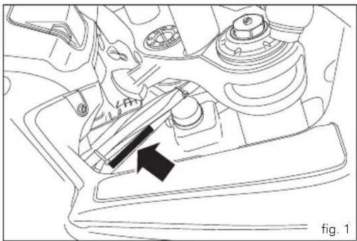
All Ducati motorcycles have two identification numbers, for frame (fig. 1) and engine (fig. 2).
Frame number
Engine number

Note
These numbers indicate the motorcycle model and should be quoted when ordering spare parts.
natural_image
Technical line drawing of a car gear shift lever assembly (no text or symbols)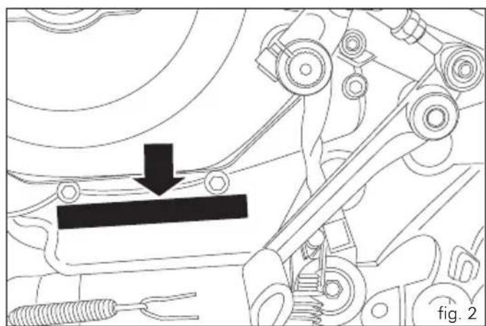
natural_image
Mechanical assembly diagram showing a lever mechanism with a black arrow indicating motion (no text or symbols present)Instrument panel (Dashboard)
Instrument panel
1) LCD Dot-Matrix, (see page14).
2) REVOLUTION COUNTER (rpm).
Indicates engine revs per minute.
3) Neutral light N (GREEN).
Illuminates when the gearbox is in neutral.
It turns on to indicate that the high beam lights are on.
5) ENGINE OIL PRESSURE LIGHT (RED).
Illuminates when engine oil pressure is too low. It must turn on at Key-On, but must turn off a few seconds after the engine has started.
It may come on briefly if the engine is very hot, but should go out again as engine speed increases.

Important
If this light (5) stays on, stop the engine or it may suffer
severe damage.
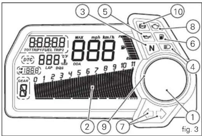

6) FUEL WARNING LIGHT (AMBER).
Comes on when fuel is low and there are about 4 litres of fuel left in the tank.
7) TURN SIGNAL LIGHTS (GREEN).
Illuminates and flashes when the turn signal is in operation.
8) "ENGINE/VEHICLE DIAGNOSIS - EOBD" LIGHT (AMBER YELLOW).

It turns on in the case of "engine" and/or "vehicle" errors and in some cases will lock the engine.

9) Limiter light "Over rev"/ traction control light "DTC" (RED) (fig. 3):
| Over rev light | |
| No limiter Off | |
| 1st threshold - no. RPM before the limiter threshold (*) | On - STEADY |
| Rev limiter (limiter engaged due to overrevving) (*) | On - Flashing |
| DTC intervention lights | |
| No intervention Off | |
| DTC intervention On - STEADY |
(*) depending on the model, each calibration of the Engine Control Unit may have a different "setting" for the thresholds that precede the rev limiter and the rev limiter itself.

Note
If the Over rev function light and the DTC intervention light should both come on at the same time, the instrument panel gives priority to the Over rev function.
10) ABS LIGHTS (AMBER YELLOW) (fig. 3).
This turns on to indicate that ABS is disabled or not functioning.
| Engine off / speed below 5 Km/h | ||
| Light off Light flashing Light steady | ||
| - | ABS disabled with the menu function “DISAB ABS” (**) | ABS enabled but not functioning yet |
| Engine on / speed below 5 Km/h | ||
| Light off Light flashing Light steady | ||
| - | ABS disabled with the menu function “DISAB ABS” | ABS enabled but not functioning yet |
| Engine on / speed above 5 Km/h | ||
| Light off Light flashing Light steady | ||
| ABS enabled and functioning | ABS disabled with the menu function “DISAB ABS” | ABS disabled and not functioning due to a problem. |
(**) The ABS should be considered actually disabled only if the light continues to flash after starting the engine.
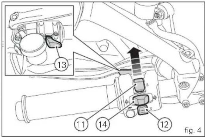
11) CONTROL BUTTON (fig. 4)
Button used to display and set instrument panel parameters with the position “▲”.
12) CONTROL SWITCH (fig. 4)
Button used to display and set instrument panel parameters with the position “▼”.
13) HIGH-BEAM FLASHER BUTTON FLASH (fig. 4)
The high-beam flasher button may also be used to for LAP functions.
The turn indicators off button may also be used for the RESET/CONFIRM function on the instrument panel and for activating the "Riding Style".


LCD unit functions

Warning
Any adjustments to the instrument panel must only be carried out when the motorcycle is stationary. Never operate the instrument panel controls while riding the motorcycle.
1) SPEEDOMETER.
Gives road speed.
2) ODOMETER.
Shows total distance travelled.
3) TRIP METER.
Indicates distance travelled since the meters (TRIP 1 and TRIP 2) were last reset.
4) TRIP FUEL METER.
Shows distance travelled on reserve fuel.
5) CLOCK.
6) FUEL LEVEL
7) ENGINE RPM INDICATOR (RPM).
8) LAP TIME, MAXIMUM SPEED AND MAXIMUM RPM RECORDING (LAP).
9) DTC INDICATOR ACTIVE/NOT ACTIVE.
10) GEAR INDICATOR.
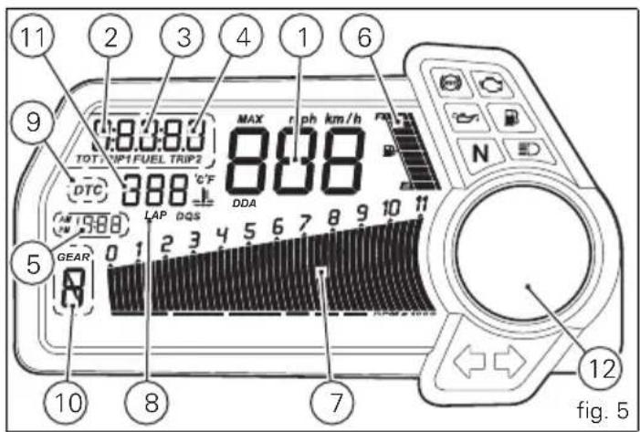
11) WATER TEMPERATURE INDICATOR. Indicates engine coolant temperature.

Important
Stop riding if the temperature reaches the maximum
value, otherwise the engine might be damaged.
12) LCD Dot-Matrix
LCD - Parameter setting/display
At the end of the check, the instrument panel always displays the Odometer (TOT) as the "main" indicator on the main display and the "riding style" on the round display.

Note
The check can be interrupted by pressing the button (1, fig. 7).
At the end of the initial check, the instrument panel will always show the "main" display that indicates the following information.
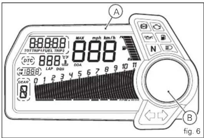
On the main LCD (A, fig. 6):
- Vehicle speed indication;
- Engine rpm indication (RPM);
- Gear indication;
- Clock indication;
- Fuel level indication
- Coolant temperature indication;
- TOT - Odometer.
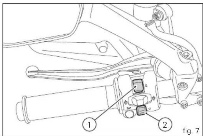
At this point, by pressing the (1, fig. 7) "▲" switch it is possible to switch to the following functions:
- TRIP1 - Trip meter 1
- TRIP2 - Trip meter 2


LCD Dot-Matrix (B, fig. 6):
- WARNING (only if active)
- ERRORS (only if active)
- DESMO SERVICE (only if active)
- SET UP - "Riding Style" indication set
At this point, by pressing the (2, fig. 7) "▼" button it is possible to switch to the following functions:
- RANGE - Remaining range
- CONS I. - Current fuel consumption
- CONS M. - Average fuel consumption
- AVG - Average speed
- AIR - Air temperature
- TIME TRIP - Trip time
Vehicle speed indicator
This function displays vehicle speed (Km/h or mph depending on the set measurement system).
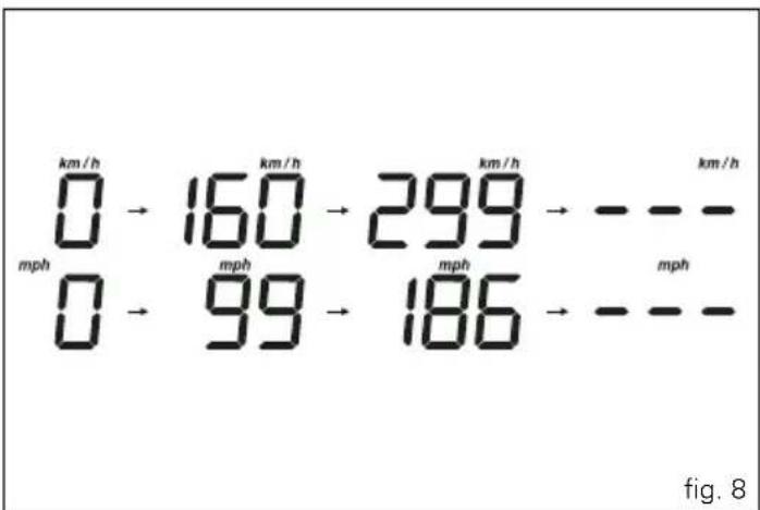
The instrument panel receives information about the actual speed (calculated in km/h) and displays the number increased by 8%.
Maximum speed displayed is 299 km/h (186 mph).
Over 299 km/h (186 mph) a series of dashes will be displayed "---" (not flashing).
other
| Time | Speed (km/h) | Speed (mph) | | :--- | :--- | :--- | | 0 | 160 | 99 | | 1 | 299 | 186 | | 2 | - | - | | 3 | - | - | | 4 | - | - | | 5 | - | - | | 6 | - | - | | 7 | - | - | | 8 | - | - |Engine rpm indicator (RPM)
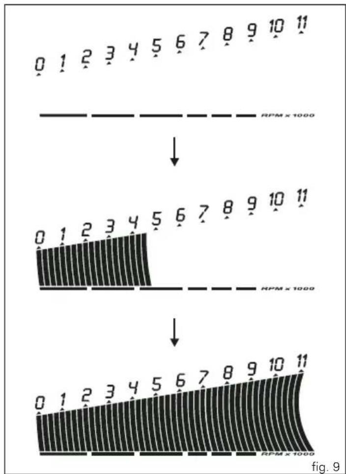
This function displays the rpms.
The instrument panel receives the engine rpm information and displays it.
This information is displayed progressively from the left to the right, identifying the rpms.


Engaged gear indicator
This function displays the gears.
The instrument panel receives information and indicates the engaged gear or "N" for neutral.

Note
In the case of a gear sensor "error", a dash "-" (not
flashing) will be displayed.

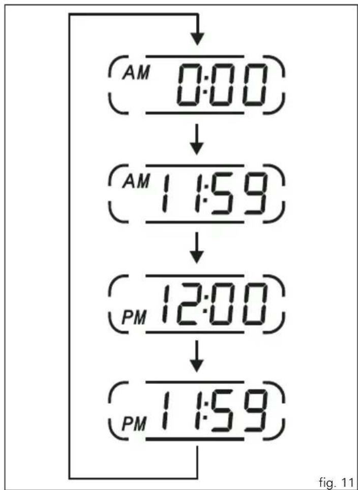
This function shows the time.
Time is always displayed as follows:
AM from 0:00 to 11:59
PM from 12:00 to 11:59
If battery power is suddenly cut off (Batt-OFF), when battery power is restored and at the next Key-On, the clock is reset and restarts from "0:00".
flowchart
graph TD
    A["AM 0:00"] --> B["AM 1:59"]
    B --> C["PM 12:00"]
    C --> D["PM 1:59"]


Fuel level indicator
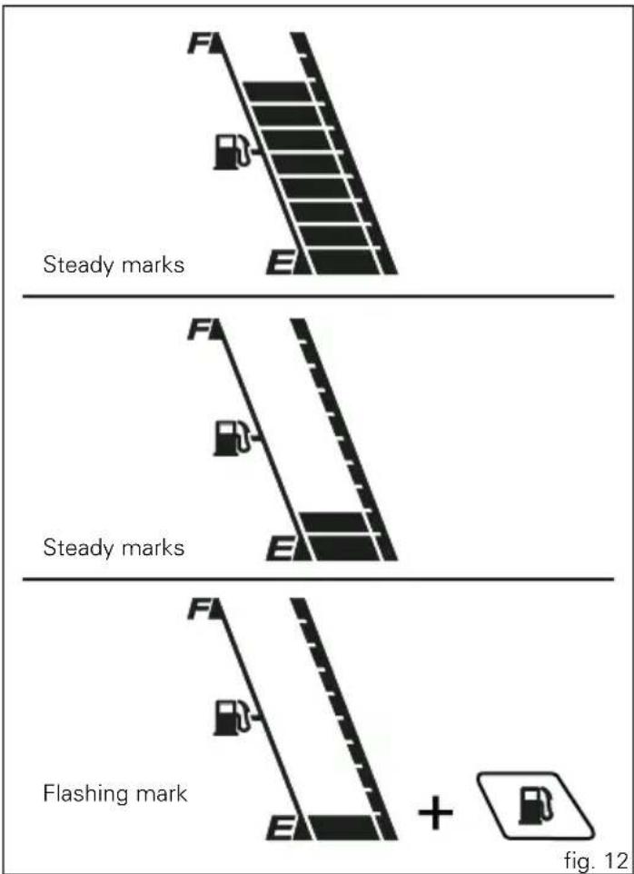
This function displays the fuel level.
The low fuel light turns on when the level goes down to 2 marks and there are still 4 litres in the tank; if the level goes down further, the last mark will be displayed flashing.

Important
If the vehicle enters the reserve status and the light
has turned on, it is recommended to turn the vehicle off when refuelling (Key-Off); if fuel is added without turning it off (Key-On and engine off) the data update may not be immediate.

Note
In the case of a level sensor "error", the bargraph
without marks is displayed and the rest of the digit will flash.
Coolant temperature
This function indicates coolant indication state.
The temperature unit of measure can be selected (°C or °F).
The reading is indicated as follows:
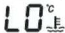
- if the reading is between - 39°C and +39°C "LO" is shown flashing on the instrument panel (steady);
- if the reading is between +40°C and +120°C it appears on the instrument panel (steady);
- if reading is +121 °C or higher, "HI" is shown flashing on the information panel.

Note
In the event of a sensor "error", a string of flashing dashes ("---") is shown and the "Engine/vehicle diagnosis -EOBD" light (8, fig. 3) comes on.
vs. EU, CND, FRA, JAP
Steady reading
Steady reading Steady reading

Flashing reading
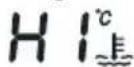
Flashing reading
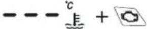
Engine Diagnosis
vs.UK, USA
Steady reading
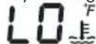
Steady reading Steady reading

Flashing reading
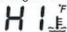
Flashing reading

Engine Diagnosis
fig. 13

Total distance covered indicator: "Odometer"
This function shows the total distance covered by the vehicle.
At Key-On the system automatically enters this function.
The odometer reading is stored permanently and cannot be reset.
If the distance travelled exceeds 99999 km (or 99999 miles), the value "99999" will be displayed permanently.
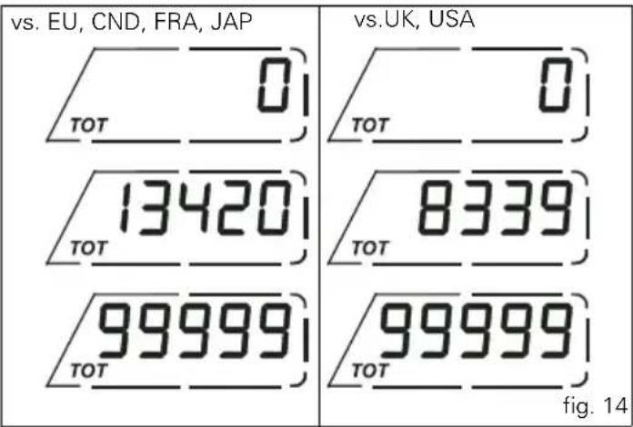
other
| Comparison | Value | | :--- | :--- | | vs. EU, CND, FRA, JAP | 0 | | vs. UK, USA | 0 | | 13420 | 8339 | | 99999 | 99999 | | Tot (Figure 14) | 99999 |"Trip 1" meter
This function shows the distance travelled since the trip meter was last reset.
Holding the button (1, fig. 7) "▲" pressed for 3 seconds when this function is displayed resets the trip meter.
When the reading exceeds 999.9, distance travelled is reset and the meter automatically starts counting from 0 again.
If the system measurement units are changed at any moment, or if there is an interruption in the power supply (Battery Off), the distance travelled is reset and the count starts from zero (considering the newly set unit of measurement).

Note
When this value is reset, also the "Average fuel
consumption", "Average speed" and "Trip time" functions are reset.
"Trip 2" meter
This function shows the distance travelled since the trip meter was last reset.
Holding the button (1, fig. 7) "▲" pressed for 3 seconds when this function is displayed resets the trip meter.
When the reading exceeds 999.9, distance travelled is reset and the meter automatically starts counting from 0 again.
If the system measurement units are changed at any moment, or if there is an interruption in the power supply (Battery Off), the distance travelled is reset and the count starts from zero (considering the newly set unit of measurement).
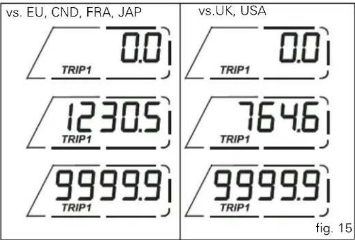
other
| Metric | Value | | :--- | :--- | | TRIP1 0.0 | 0.0 | | TRIP1 1230.5 | 0.0 | | TRIP1 764.6 | 0.0 | | TRIP1 9999.9 | 0.0 | | TRIP1 9999.9 | 0.0 | fig. 15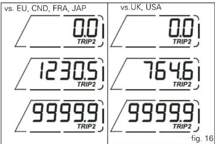
other
| Region | Value | | :--- | :--- | | vs. EU, CND, FRA, JAP | 0.0 | | vs. UK, USA | 0.0 | | 1230.5 TRIP2 | 764.6 | | 9999.9 TRIP2 | 9999.9 | fig. 16
Indication if the DTC function is active/not active
This function indicates if DTC (Ducati Traction Control) is active.
When "DTC" is not lit up in the inside the rim, this means that the function is disabled.
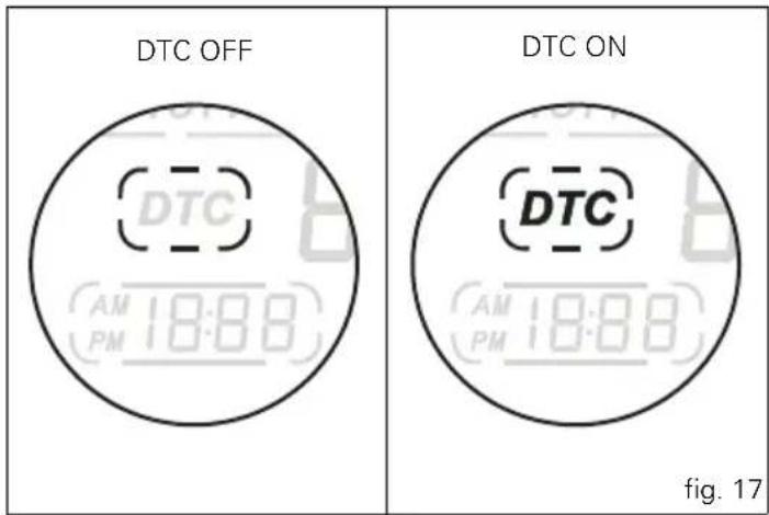
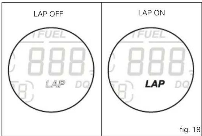
Indication if the LAP function is active/not active
This function indicates if LAP (Lap number) is active.
When "LAP" is not lit up, this means that the function has been switched off.
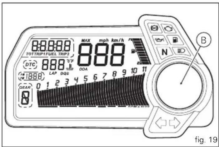
Warning indication (Alarms/Signals)
The instrument panel shows some signals/malfunctions in real time on the circular "Dot-Matrix" display (B, fig. 19) that are not dangerous for correct vehicle operation.
At Key-On (at the end of the check) one or more "warnings" are displayed if they are active.
If a "warning" is activated during operation, the current indication on the circular "Dot-Matrix" display (B, fig. 19) will switch automatically to the indicator.
If there are multiple indicators, they will scroll automatically every 3 seconds.

Note
No signal lights turn on if one or more "warnings" are activated.
The following "warnings" could be displayed:
- Battery level;
- Traction control;
- Hands free key;
- Hands free key battery level;
- Coolant temperature;
- Steering release error.
When one or more "warnings" are active, it is possible to go to other functions by pushing button (2, fig. 7) "▼".


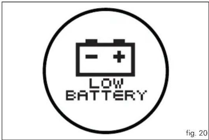
"Low" battery level
The activation of this "warning" indicates that the status of the battery vehicle is low.
It is activated when the battery voltage is ≤ 11.7 Volt.

Note
In this case, Ducati recommends charging the battery as soon as possible with the specific device, as it is possible that the vehicle will not start.
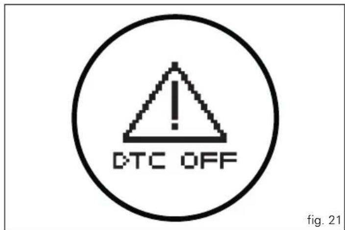
Traction Control (DTC) deactivated
The activation of this "warning" indicates that DTC (Ducati Traction Control) has been turned off.

Note
In this case, Ducati recommends being very careful when riding as the vehicle behaviour will be different in comparison to when operating with the Traction Control activated.
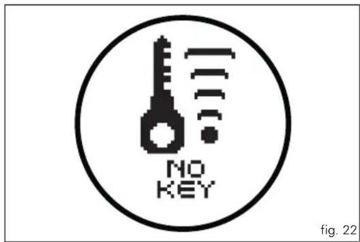
Hands Free key (HF) not recognised
The activation of this "warning" indicates that the Hands Free system does not detect the active key (1, fig. 59) near the vehicle.

Note
In this case, Ducati recommends checking that the active key (1, fig. 59) is near the vehicle (and has not been lost) and that it functions properly.
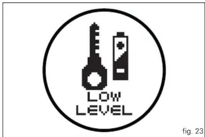
"Low" Hands Free key (HF) battery level
The activation of this "warning" indicates that the Hands Free system has detected that the battery that permits the active key (1, fig. 59) to communicate and turn the vehicle on is almost discharged.

Note
In this case, Ducati recommends replacing the battery as soon as possible as described in the paragraph "Replacing the active key battery" (page 86).


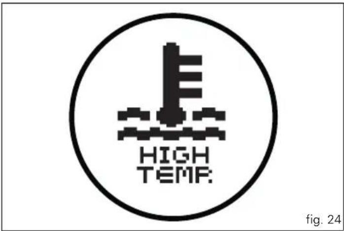
"High" engine coolant temperature
The activation of this "warning" indicates that the engine coolant temperature is high.
It is activated when the temperature reaches 121°C (250°F).

Note
In this case, Ducati recommends stopping and shutting off the engine immediately; make sure that the fans are working.
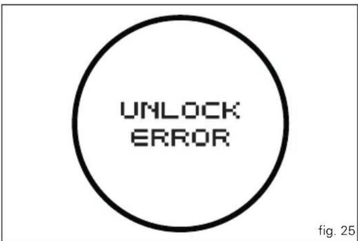
Steering release error - Steering still locked
The activation of this "warning" indicates that the Hands Free System was not able to extract the steering lock.

Warning
In this case, Ducati recommends turning the vehicle off and on (Key-Off / Key-On) holding the handlebar pressed down to the end stop. If the signal remains (and the steering does not "release") contact a Ducati Dealer or Authorised Service Centre.
Instrument panel diagnosis
This function identifies any abnormal vehicle behaviours.
The instrument panel activates any abnormal vehicle behaviours in real time (ERRORS).
At Key-On (at the end of the check) one or more "ERRORS" are displayed (only if they are active).
If an “error” is activated during operation, the current indication on the circular “Dot-Matrix” display (B, fig. 6) will switch automatically to the indicator.
If there are multiple errors, they will scroll automatically every 3 seconds; The "Engine/vehicle diagnosis - EOBD" light (8, fig. 3) always turns on when one or more errors are activated.
When one or more errors are active, it is possible to go to other functions by pushing the button (2, fig. 7) "▼".
The table below shows the errors that can be displayed.

When one or more errors are displayed, always contact a Ducati Dealer or Authorised Service Centre.
WARNING LIGHT ERROR MESSAGE ERROR
| BBS/DTC Black Box / Traction Control control unit | |
| GEAR SENSOR Gear sensor | |
| FUEL SENSOR Fuel Level Sensor | |
| SPEED SENSOR Speed sensor | |
| EXVL ERROR Exhaust valve starter motor | |
| UNKNOWN DEVICE Unknown control unit |
WARNING LIGHT ERROR MESSAGE ERROR
| DEVICE ECU ECU control unit not functioning | |
| DEVICE DASHBOARD Instrument panel not functioning | |
| DEVICE HANDS FREE Hands Free control unit not functioning | |
| DEVICE BBS - DTC Black Box control unit not functioning | |
| THROTTLE POSITION Incorrect throttle position | |
| ACCELER. POSITION Incorrect accelerator position | |
| ETV MOTOR Throttle starter motor not functioning | |
| ETV RELAY Relay starter motor not functioning | |
| PRESSURE Atmospheric pressure sensor | |
| ENGINE TEMPERAT. Engine temperature | |
| AIR TEMP. Air temperature | |
| FUEL INJECTION Injection relay |
WARNING LIGHT ERROR MESSAGE ERROR
| COIL Coil | |
| INJECTOR Injector | |
| PICK-UP Timing/rpm sensor | |
| LAMBDA Lambda sensor | |
| LAMBDA HEATER Lambda heater | |
| FAN RELAY Fan relay | |
| HIGH BEAM High beam headlight relay | |
| LOW BEAM Low beam headlight relay | |
| CLAXON Horn | |
| CAN CAN communication line | |
| BATTERY Battery voltage (HIGH or LOW) | |
| DEVICE DES Suspension ECU not functioning |
E
WARNING LIGHT ERROR MESSAGE ERROR
| DES GENERIC Problem related to suspension ECU operation | |
| STOP LIGHT Rear stop light | |
| ECU GENERIC ECU error | |
| KEY ERROR HF communication problem | |
| HANDS FREE GENERIC Hands Free ECU error | |
| DES FRONT COMPRESS. Problem with the stepper that adjusts suspension front compression | |
| DES FRONT REBOUND Problem with the stepper that adjusts front suspension rebound | |
| DES REAR COMPRESS. Problem with the stepper that adjusts suspension rear compression | |
| DES REAR REBOUND Problem with the stepper that adjusts suspension rear rebound | |
| DES PRELOADER ADJUSTER Problem with the DC starter motor that adjusts the rear suspension preload. |
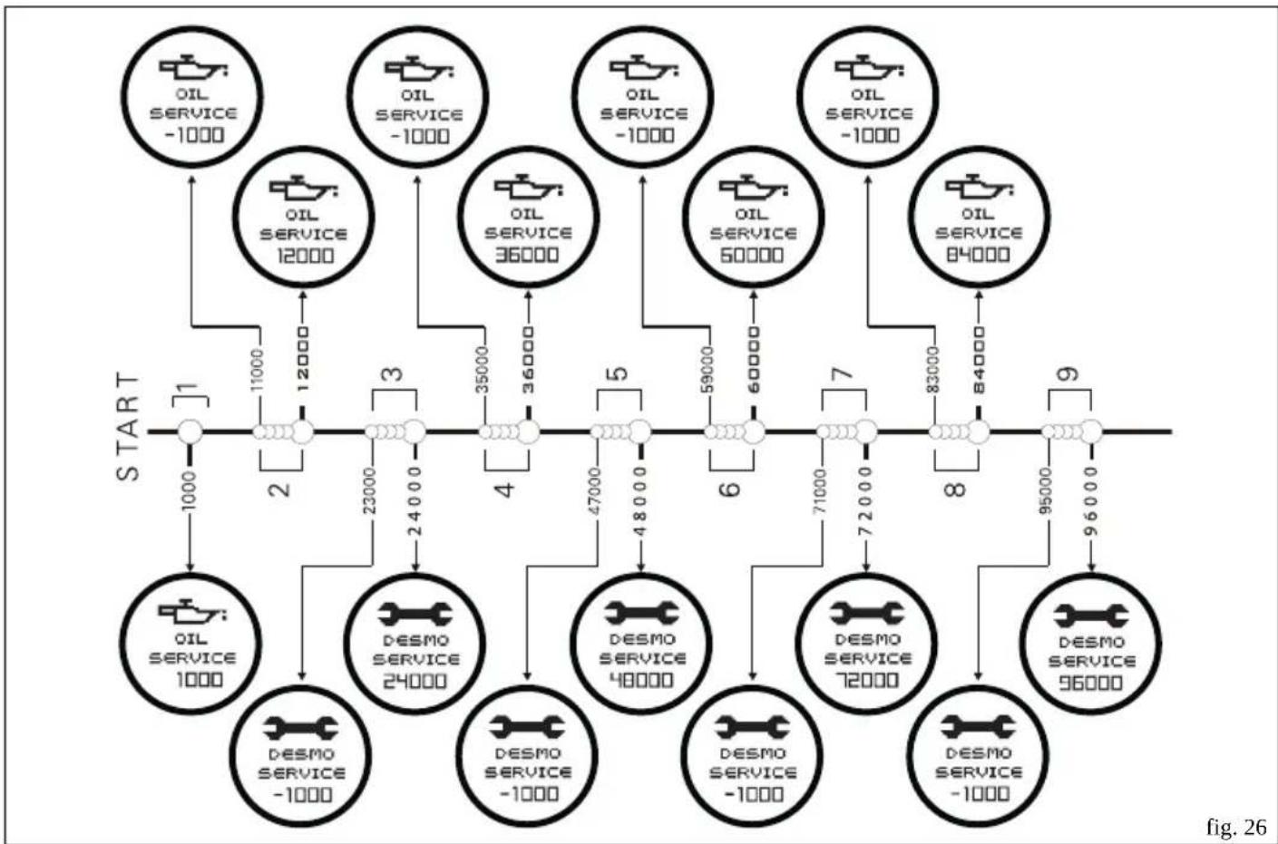
Maintenance indicator
This function indicates that the vehicle is about to or has travelled a distance for which an Authorised Ducati Service Centre should be contacted to have the general maintenance or oil change performed.
Residual range indication when the SERVICE is due
When 1000 Km (621 miles) are left until reaching the mileage programmed by Ducati for having the "SERVICE"
performed, the instrument panel activates (at the end of the initial check) the indication of which type of service should be performed and the residual range (count-down).
The indication is activated each time the motorcycle is turned on (Key-On) for 5 seconds (flashing).
The residual range is updated every 100 Km (-1000, -900, -800, -700, etc.....).

Warning
This message can only be reset by the Ducati Dealer or
Authorised Service Centre that performs the maintenance.
Indication of range reached for SERVICE
If you reach the mileage programmed by Ducati, the information panel will activate (at the end of the initial check) the indication that you should go to a Ducati Dealer or Authorised Service Centre to have the scheduled maintenance "DESMO SERVICE" or "OIL SERVICE" performed.
The indication is activated each time the motorcycle is turned on (Key-On) (not flashing); pressing the button (2, fig.7) “▼” the other functions can be displayed;
The indication will remain until it is reset and it can be displayed at any moment by scrolling the functions.

Warning
This message can only be reset by the Ducati Dealer or
Authorised Service Centre that performs the maintenance.

Note
The distance travelled thresholds are defined in an "alute" sense and do not account for when the "reset" last for the indication is made by the Authorised Ducati ce Centre.

Maintenance table
| Indicator Mileage travelled count | down -1000 DESMO SERVICE | count down -1000 OIL SERVICE | DESMO SERVICE | OIL SERVICE | |
| 1 1000 | ● | ||||
| 2 | 11000 | ● | |||
| 12000 ● | |||||
| 3 | 23000 | ● | |||
| 24000 ● | |||||
| 4 | 35000 | ● | |||
| 36000 ● | |||||
| 5 | 47000 | ● | |||
| 48000 ● | |||||
| 6 | 59000 | ● | |||
| 60000 ● | |||||
| 7 | 71000 | ● | |||
| 72000 ● | |||||
| 8 | 83000 | ● | |||
| 84000 ● | |||||
| 9 | 95000 | ● | |||
| 96000 ● | |||||
flowchart
graph TD
    A["START"] --> B["1"]
    B --> C["2"]
    C --> D["3"]
    D --> E["4"]
    E --> F["5"]
    F --> G["6"]
    G --> H["7"]
    H --> I["8"]
    I --> J["9"]
    J --> K["96000"]

    subgraph_OIL_SERVICE_1["OIL SERVICE -1000"]
        L["1000"] --> M["2"]
        M --> N["3"]
        N --> O["4"]
        O --> P["5"]
        P --> Q["6"]
        Q --> R["7"]
        R --> S["8"]
        S --> T["9"]
    end

    subgraph_OIL_SERVICE_2["OIL SERVICE -12000"]
        U["12000"] --> V["23000"]
        V --> W["35000"]
        W --> X["47000"]
        X --> Y["48000"]
        Y --> Z["71000"]
        Z --> AA["72000"]
        AA --> AB["83000"]
        AB --> AC["84000"]
    end

    subgraph_OIL_SERVICE_3["OIL SERVICE -1000"]
        AD["1000"] --> AE["36000"]
        AE --> AF["48000"]
        AF --> AG["71000"]
        AG --> AH["72000"]
        AH --> AI["83000"]
        AI --> AJ["84000"]
    end

    subgraph_OIL_SERVICE_4["OIL SERVICE -1000"]
        AK["1000"] --> AL["48000"]
        AL --> AM["71000"]
        AM --> AN["72000"]
        AN --> AO["83000"]
        AO --> AP["84000"]
    end

    subgraph_DESMO_SERVICE_5["DESMO SERVICE -1000"]
        AQ["124000"] --> AR["24000"]
        AR --> AS["35000"]
        AS --> AT["47000"]
        AT --> AU["48000"]
        AU --> AV["71000"]
        AV --> AW["72000"]
        AW --> AX["83000"]
        AX --> AY["84000"]
    end

    subgraph_DESMO_SERVICE_6["DESMO SERVICE -1000"]
        AZ["124000"] --> BA["24000"]
        BA --> BB["35000"]
        BB --> BC["47000"]
        BC --> BD["48000"]
        BD --> BE["71000"]
        BE --> BF["72000"]
        BF --> BG["83000"]
        BG --> BH["84000"]
    end

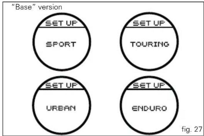
SET UP - "Riding Style set" indication
This function indicates the "Riding Style" set for the vehicle. Four "Riding Styles" are available: SPORT, TOURING, URBAN and ENDURO.
Each riding style can be changed using the "Riding Style" function.
In the "base" version, only the set riding style is indicated.
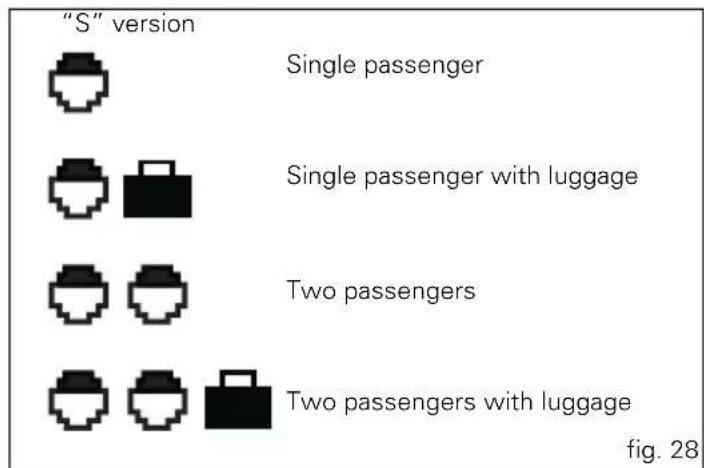
In the "S" version, the setup (fig. 28) and the riding style (fig. 29) that are set are indicated.
"S" version
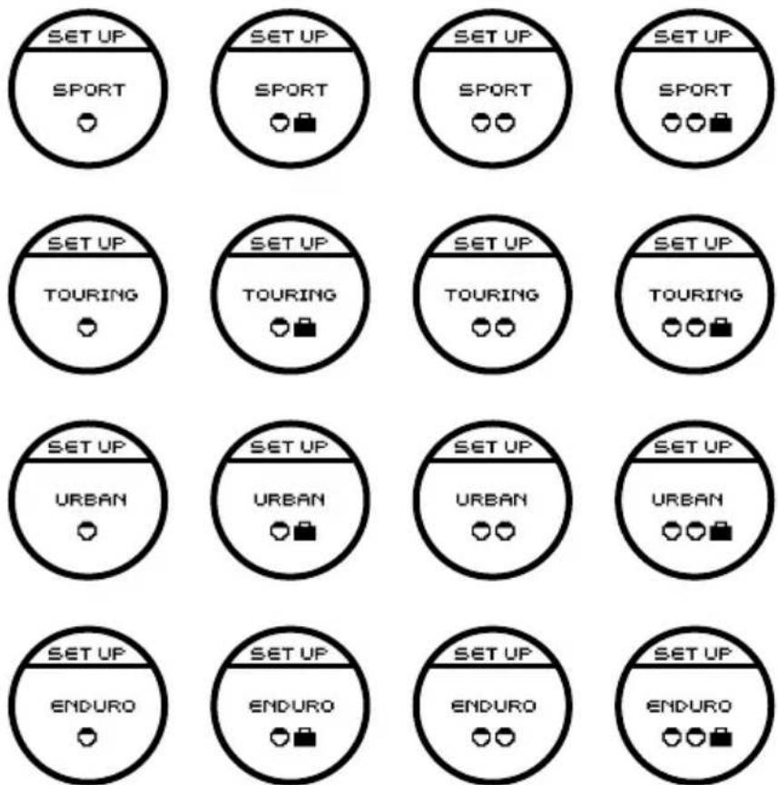
fig. 29

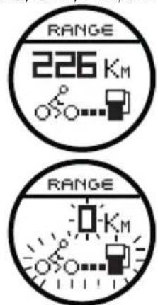
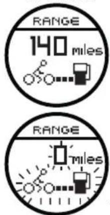
"RANGE" indicator - remaining range
This function indicates the distance that can be travelled with the fuel currently in the tank.
The calculation is made based on the fuel level and an average consumption in reference to the last 90 seconds of driving (not the average fuel consumption "CONS M.").
If you refuel adding more than 4 litres of fuel with the vehicle switched off (Key-Off), at the subsequent Key-On, the remaining range reading will be updated instantaneously and will be calculated based on the new fuel level and an average fuel consumption of 18.0 Km/L; otherwise (that is, if you add less than 4 litres) the reading will only be updated after the vehicle is in movement (not instantaneously).
When the range arrives to "0" the indication will flash together with the symbol (motorcycle + fuel pump).
vs. EU, CND, FRA, JAP
vs. UK, USA

Warning
It is recommended to turn off the motorcycle (Key-Off) when refuelling; if adding fuel without turning off the motorcycle (Key-On/engine off), the reading will be updated as soon as the vehicle starts to move (speed greater than zero).

Warning
The residual range that is measured is an approximate value; Ducati recommends not trying to use all the residual range indicated.
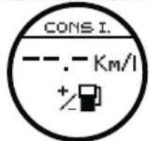
Indicator "CONS I." - Instantaneous fuel consumption
This function indicates the "instantaneous" fuel consumption.
The calculation is made considering the quantity of fuel used and the distance travelled during the last second.
The active calculation phase only occurs when the engine is running and the vehicle is moving (moments when the vehicle is not moving when speed is equal to 0 and/or when the engine is off are not considered). Dashes “- - - .” are shown on the display when the calculation is not made.
vs. EU, CND, FRA, JAP
vs. UK, USA
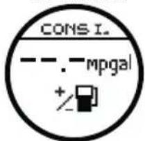
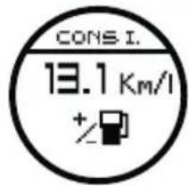
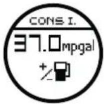
fig.31
Indicator "CONS M." - Average fuel consumption
This function indicates the "average" fuel consumption.
The calculation is made considering the quantity of fuel used and the km travelled since the last Trip 1 reset. When Trip 1 is reset, the value is set to zero and the first available value is shown on the display 10 seconds after the reset. Dashes “--.-” are shown on the display during the first 10 seconds when the value is not yet available.
The active calculation phase only occurs when the engine is running and the vehicle is moving (moments when the vehicle is not moving when speed is equal to 0 and/or when the engine is off are not considered).
vs. EU, CND, FRA, JAP
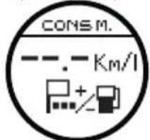
vs. UK, USA
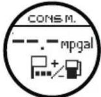
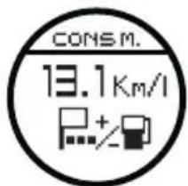
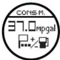
fig. 32

Indicator "AVG" - Average speed
This function shows the average speed of the motorcycle. The calculation is made considering the distance and time travelled since the last Trip 1 reset. When Trip 1 is reset, the value is set to zero and the first available value is shown on the display 10 seconds after the reset. Dashes “- - -” are shown on the display during the first 10 seconds when the value is not yet available.
The active calculation phase only occurs when the engine is running and the vehicle is moving (moments when the vehicle is not moving when speed is equal to 0 and/or when the engine is off are not considered).
The calculated value is displayed increased by 8% to align it with the vehicle indicated speed.
Air temperature indicator
This function shows the external temperature.
Display limits: -39^ ÷ +124^
In the event of a sensor FAULT (-40°C,+125°C or disconnected), a string of dashes “- - -” (not flashing) is displayed and the “Engine/Vehicle Diagnosis - EOBD” light (8, fig. 3) comes on and an error is indicated inside “Errors” Menu.

Note
When the vehicle is stopped, the engine heat could
influence the displayed temperature.
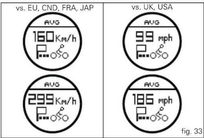
other
| Region | Metric | Value | | :--- | :--- | :--- | | EU | 160 Km/h | 160 | | EU | 299 Km/h | 299 | | CND | 160 Km/h | 160 | | CND | 299 Km/h | 299 | | FRA | 160 Km/h | 160 | | FRA | 299 Km/h | 299 | | JAP | 160 Km/h | 160 | | JAP | 299 Km/h | 299 | | UK | 160 mph | 160 | | UK | 299 mph | 299 | | USA | 160 mph | 160 | | USA | 299 mph | 299 | | USA | 186 mph | 186 | The diagram is labeled 'fig. 33' at the bottom right. The values for each metric are explicitly labeled on the circular diagrams.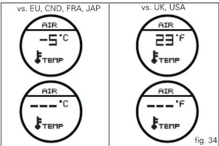
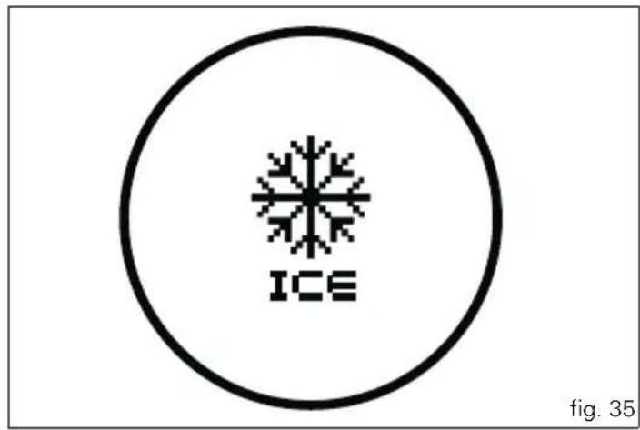
When the detected temperature drops to 4°C (39°F), the display warns that the formation of ice is possible. The indication turns off when the temperature rises to 6°C (43°F).

Warning
This warning does not exclude the possibility of icy road sections even at temperatures above 4°C (39°F); when external temperatures are "low" it is always recommended to drive carefully, particularly on sections that are not exposed to the sun and/or on bridges.
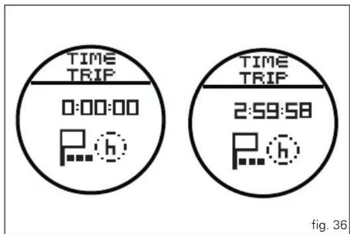
Indicator "TIME TRIP" - Trip time
This function shows the vehicle trip time.
The calculation is made considering the time travelled since the last Trip 1 reset. When Trip 1 is reset, the value is set to zero.
The active time calculation phase only occurs when the engine is running and the vehicle is moving (when the vehicle is not moving and the speed is equal to 0 and/or when the engine is off, the time is automatically stopped and automatically restarts when the active counting phase restarts).


"Riding Style" function (riding style change)
This function changes the motorcycle riding style.
Each riding style is associated with a different intervention level of the traction control (DTC - Ducati Traction Control) and different engine power and output.
For the "S" version with electronic suspension, each riding style change is also associated with different motorcycle setup.
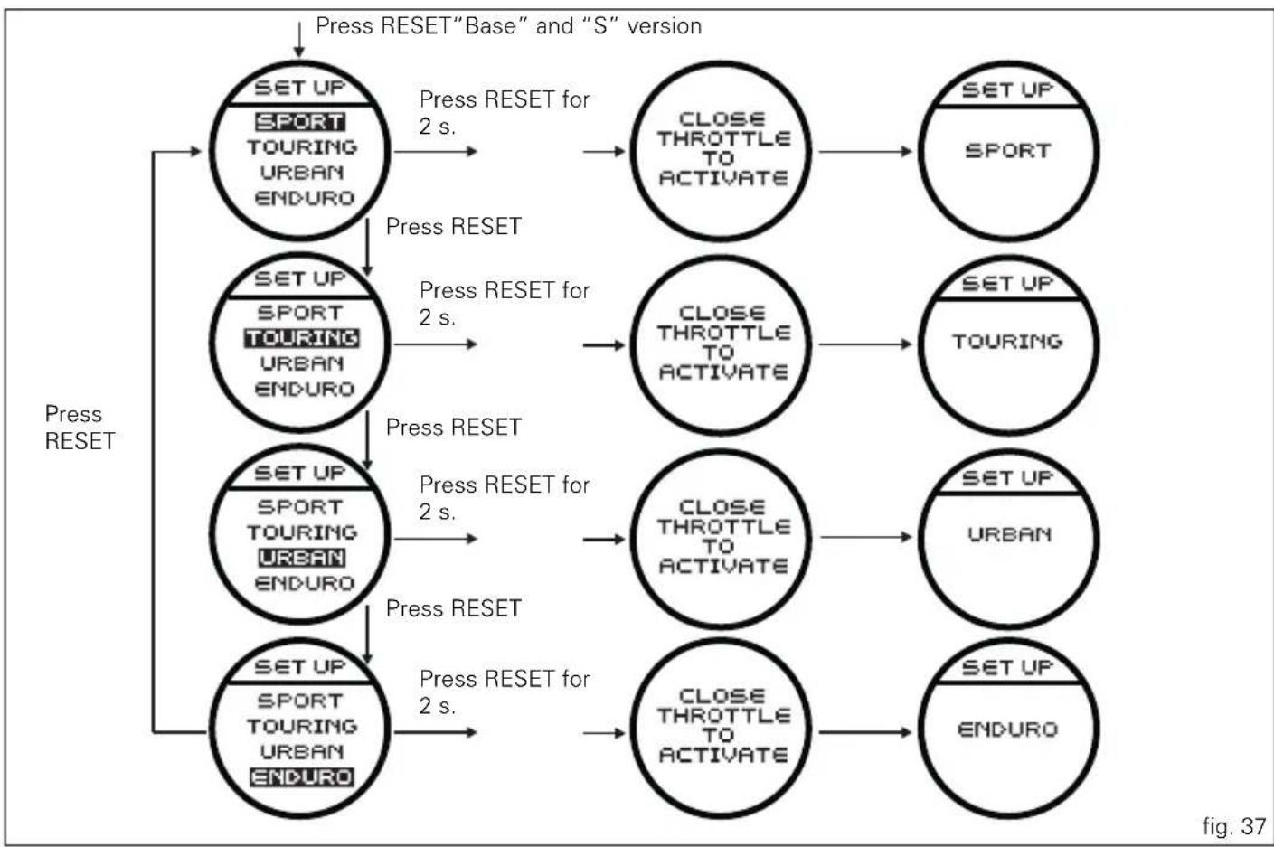
To change the motorcycle riding style, press the reset button once (14, fig. 4) and the "SET UP" menu will appear on the circular display (B, fig. 6).
The desired riding style can be selected by pressing the same reset button multiple times (14, fig. 4). Press the same button for 3 seconds to confirm the riding style.
If the twistgrip is closed (vehicle stopped) the riding style change will occur immediately; if the twistgrip grip is open (vehicle moving) the message "CLOSE THROTTLE TO ACTIVATE" will appear on the display, which means that the throttle must be closed; this message will appear for 5 seconds, during which the gas must be closed in order to activate the new riding style.
If the twistgrip is not closed after 5 seconds, the procedure is aborted (no change is made).
If the "SET UP" menu is activated and the rest button is not pressed (14, fig. 4) for 10 consecutive seconds, the instrument panel will automatically exit the display mode without making any change.

Warning
Ducati recommends changing the riding style when the vehicle is stopped. If the riding style is changed while riding, be very careful (it is recommended to change the riding style at a low speed).
flowchart
graph TD
    A["Press RESET"] --> B["SET UP SPORT TOURING URBAN ENDURO"]
    B --> C["Press RESET for 2 s."]
    C --> D["CLOSE THROTTLE TO ACTIVATE"]
    D --> E["SET UP SPORT"]
    B --> F["SET UP SPORT TOURING URBAN ENDURO"]
    F --> G["Press RESET for 2 s."]
    G --> H["CLOSE THROTTLE TO ACTIVATE"]
    H --> I["SET UP TOURING"]
    B --> J["SET UP SPORT TOURING URBAN ENDURO"]
    J --> K["Press RESET for 2 s."]
    K --> L["CLOSE THROTTLE TO ACTIVATE"]
    L --> M["SET UP URBAN"]
    J --> N["SET UP SPORT TOURING URBAN ENDURO"]
    N --> O["Press RESET for 2 s."]
    O --> P["CLOSE THROTTLE TO ACTIVATE"]
    P --> Q["SET UP ENDURO"]


"LOAD" FUNCTION (setup change)
This function, which is only available in the "S" version, changes the vehicle setup.
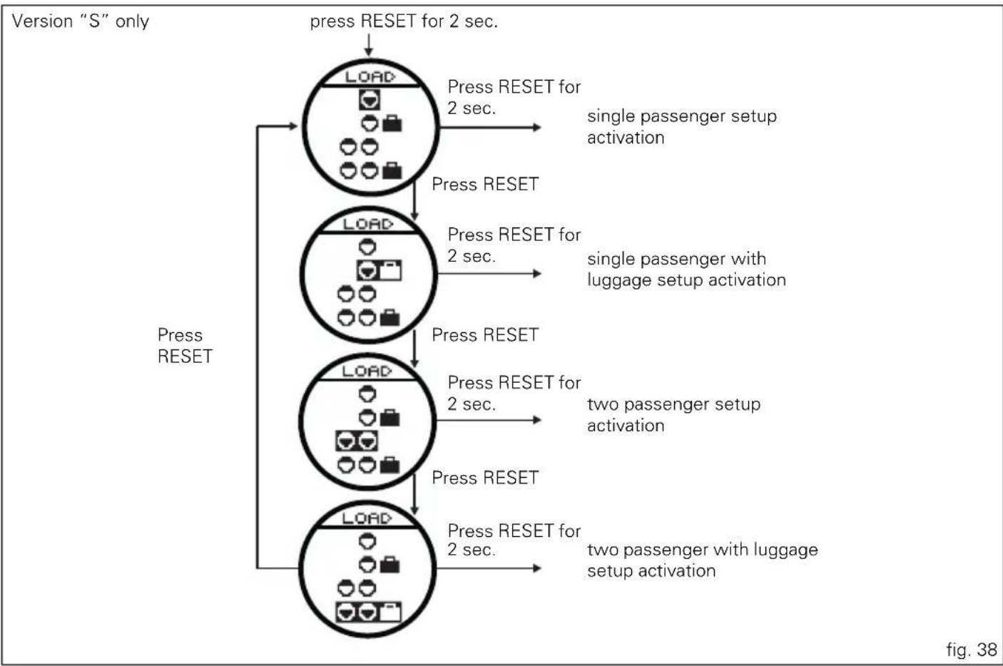
Each individual riding style is associated with four different setups (fig. 28).
To change the vehicle setup, press the reset button (14, fig. 4) for 3 seconds consecutively and the "LOAD" menu will appear on the circular display (B, fig. 6).
The desired setup can be selected by pressing the same reset button multiple times (14, fig. 4). To confirm the setup, press the same reset button again for 3 seconds (14, fig. 4).
At the end of the 3 seconds, the change occurs immediately and the instrument panel exits the display mode automatically.
Example: if a setup change is made from "individual passenger" to "passenger with luggage", the change may vary depending on the set riding style (the "passenger with luggage" setup may have different adjustments depending on if the riding style that is set to SPORT, TOURING, URBAN or ENDURO).
If the "LOAD" menu is activated and the rest button is not pressed (14, fig. 4) for 10 consecutive seconds, the instrument panel will automatically exit the display mode without making any change.

Warning
The setup change can lead to a different motorcycle riding style; it is recommended to be careful if changing the setup while riding (it is recommended to change the setup at a low speed).
flowchart
graph TD
    A["Press RESET"] --> B["1. Load"]
    B --> C["2. Press RESET for 2 sec."]
    C --> D["3. Load"]
    D --> E["4. Press RESET for 2 sec."]
    E --> F["5. Load"]
    F --> G["6. Press RESET for 2 sec."]
    G --> H["7. Two passenger setup activation"]
    H --> I["Two passenger with luggage setup activation"]
    I --> J["Single passenger setup activation"]
    J --> K["press RESET for 2 sec."]
    K --> L["press RESET for 2 sec."]
    L --> M["press RESET for 2 sec."]
    M --> N["press RESET for 2 sec."]


"Setting" menu
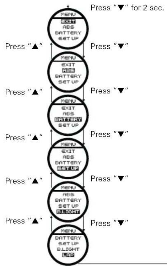
This menu is used to set/enable some motorcycle functions.
To access the "setting menu" press the button (2, fig. 7)
“▼” for 2 seconds.

Note
Once this menu has been accessed, it is not possible
to scroll the functions on the main display (A, fig. 6).

Important
For safety reasons, the setting menu can only be
accessed when motorcycle speed is lower than or equal to 20 Km/h. If this menu is open and the speed of the motorcycle exceeds 20 km/h, the instrument panel automatically exits the menu and returns to the “main” display.
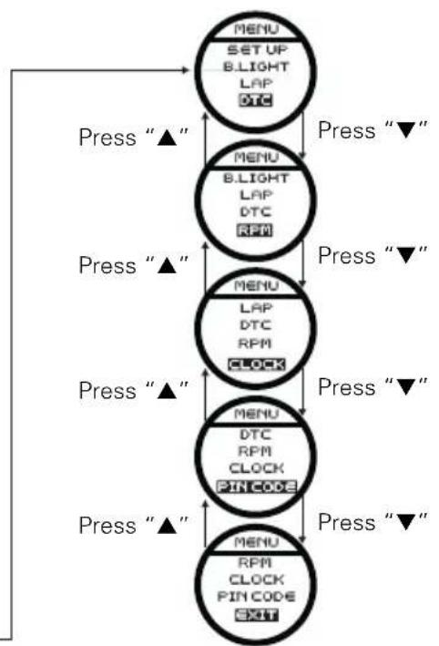
The setting menu contains the following "items":
- EXIT
- ABS
- BATTERY
- SETUP
- B.LIGHT
- LAP
- DTC
- RPM
- C L O C K
- PIN CODE
- EXIT
To exit the setting menu, use button (1, fig. 7) “▲” or button (2, fig. 7) “▼” to select “EXIT” (present at the beginning and the end of the menu item list) and press the reset button (14, fig. 4).
flowchart
graph TD
    A["MENU EXIT ABS BATTERY SET UP"] -->|Press "▲"| B["MENU EXIT ABS BATTERY SET UP"]
    B -->|Press "▼" for 2 sec.| C["MENU EXIT ABS BATTERY SET UP"]
    C -->|Press "▲"| D["MENU EXIT ABS BATTERY SET UP"]
    D -->|Press "▼"| E["MENU EXIT ABS BATTERY SET UP"]
    E -->|Press "▲"| F["MENU EXIT ABS BATTERY SET UP BLIGHT"]
    F -->|Press "▼"| G["MENU EXIT ABS BATTERY SET UP BLIGHT LAP"]
    G -->|Press "▲"| H["Press "▼""]
flowchart
graph TD
    A["MENU SETUP BLIGHT LAP DTC"] -->|Press "▲"| B["MENU BLIGHT LAP DTC RPM"]
    B -->|Press "▼"| C["MENU LAP DTC RPM CLOCK"]
    C -->|Press "▲"| D["MENU DTC RPM CLOCK PIN CODE"]
    D -->|Press "▼"| E["MENU RPM CLOCK PIN CODE EXIT"]
fig. 39

ABS disabling function
This function disables the ABS control unit.
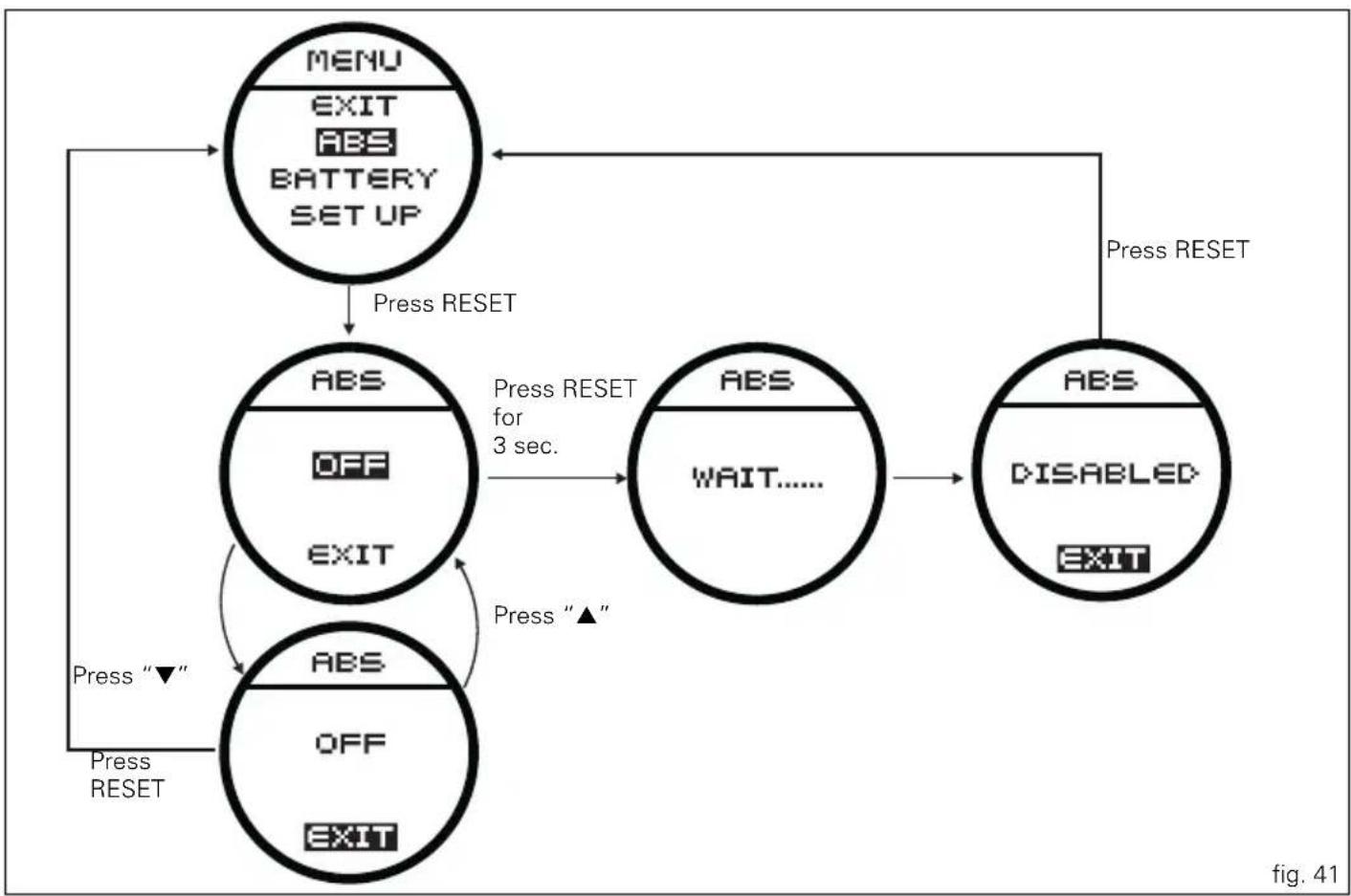
To display the function, enter the "Setting" menu page 46 and access the "ABS" page.
After accessing the display, press the reset button (14, fig. 4) for 3 seconds to disable ABS.
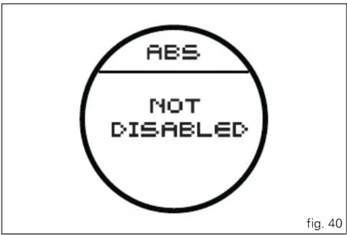
The instrument panel will send the disabling request ("WAIT...." will appear on the circular display (B, fig. 6) for 6 seconds) and then if ABS is actually disabled, "DISABLED" will appear on the circular display (B, fig. 6).
The ABS light (10, fig. 3) signals the disabling, switching from an "off" status to "flashing".
To reenable the ABS system, turn the motorcycle off and on (Key-Off/Key-On).

Note
If the disabling request was not successful, the instrument panel will display "NOT DISABLED" in the circular display (B, fig. 6).
In this case, repeat the procedure. If the problem persists, contact your Ducati dealer or Authorised Service Centre.
flowchart
graph TD
    A["MENU\nEXIT\nABS\nBATTERY\SET UP"] -->|Press RESET| B["ABS\nOFF\nEXIT"]
    B -->|Press RESET for 3 sec.| C["ABS\nWAIT......"]
    C --> D["ABS\nDISABLED\nEXIT"]
    D -->|Press RESET| A
    B -->|Press "▲"| E["ABS\nOFF\nEXIT"]
    E -->|Press "▼"| F["Press RESET"]
    F --> A


Battery voltage indicator (BATTERY)
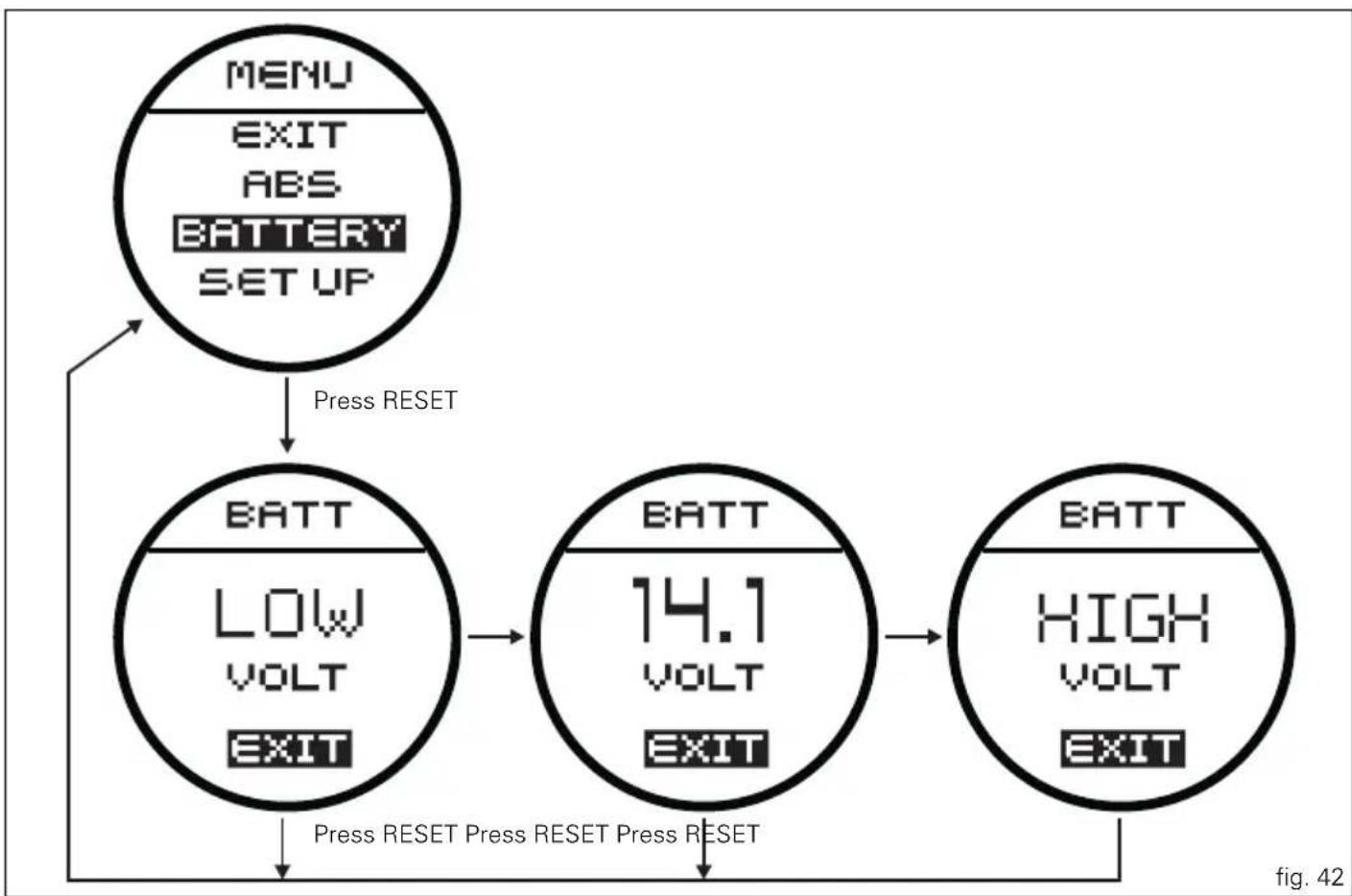
This function describes the battery voltage indicator. To display the function, enter the "Setting" menu page 46 and access the "BATTERY" page. The information will be displayed as follows:
- if battery voltage is between 11.8 and 14.9 Volt the reading will be displayed steady;
- if battery voltage is between 11.0 and 11.7 Volt the reading will be displayed flashing;
- if battery voltage is between 15.0 and 16.0 Volt the reading will be displayed flashing;
- if battery voltage is equal to or less than 10.9 Volt, "LOW" is shown flashing and the "Vehicle/Engine Diagnosis - EOBD" light (8, fig. 3) comes on;
- if battery voltage is equal to or greater than 16.1 Volt, "HIGH" is shown flashing and the "Vehicle/Engine Diagnosis - EOBD" light (8, fig. 3) comes on.

Note
Dashes “---” appear if the reading is not available.
flowchart
graph TD
    A["MENU\nEXIT\nABS\nBATTERY\nSET UP"] -->|Press RESET| B["BATT\nLOW\nVOLT\nEXIT"]
    B --> C["BATT\n14.1\nVOLT\nEXIT"]
    C --> D["BATT\nHIGH\nVOLT\nEXIT"]
    D --> E["Figure 42"]


"Riding Style" customisation
This function customises each riding style.
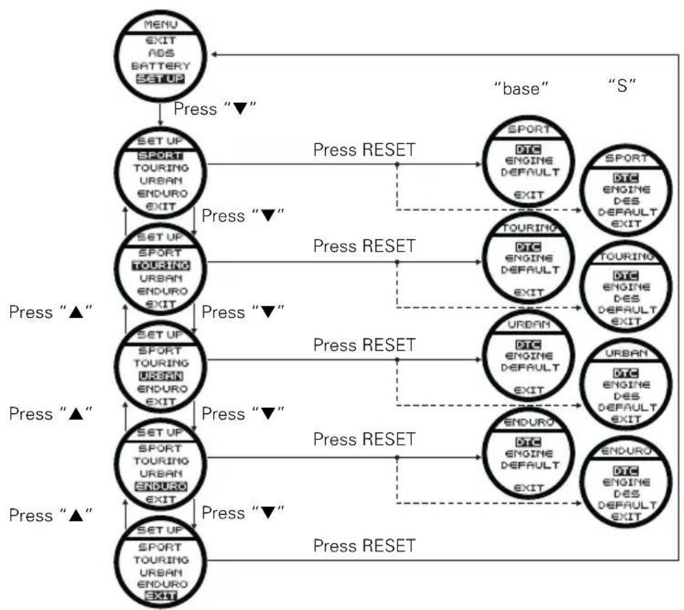
To display the function, enter the "Setting" menu page 46 and access the "SET UP" page.
When accessing the function, the four riding styles appear on the circular display (B, fig. 6); to customise the parameters, use buttons (1, fig. 7) “▲” and (2, fig. 7) “▼” to select the riding style to be changed and press the reset button (14, fig. 4) to confirm.
The parameters that can be “customised” are “DTC” (Ducati Traction Control), “ENGINE” and, only for “S” versions, the electronic suspension regulations “DES”.
Any parameter change made is saved in the memory also after a Battery-Off.
To change the DTC parameters see the "DTC (Ducati Traction Control)" paragraph page 54.
To change the Engine parameters see the "ENGINE (engine power control)" paragraph page 58.
To change the electronic suspension parameters (only for "S" versions) see the "DES (Ducati Electronic Suspension)" paragraph.
The parameters set by Ducati for each individual driving style can be reset with the "DEFAULT" function.
To reset the "default" parameters see the "DEFAULT (Resetting Ducati default parameters)" paragraph page 68.

Warning
Changes should only be made to the parameters by people who are experts in motorcycle setup; if the parameters are changed accidentally, use the "DEFAULT" function to reset the parameters.
flowchart
graph TD
    A["MENU EXIT ABS BATTERY SETUP"] -->|Press “▼”| B["SPORT TOURING URBAN ENDURO EXIT"]
    B -->|Press “▼”| C["SPORT TOURING URBAN ENDURO EXIT"]
    C -->|Press “▼”| D["SPORT TOURING URBAN ENDURO EXIT"]
    D -->|Press “▼”| E["SPORT TOURING URBAN ENDURO EXIT"]
    E -->|Press “▼”| F["SPORT TOURING URBAN ENDURO EXIT"]
    F -->|Press “▼”| G["SPORT TOURING URBAN ENDURO EXIT"]
    G -->|Press “▼”| H["SPORT TOURING URBAN ENDURO EXIT"]
    H -->|Press “▼”| I["SPORT TOURING URBAN ENDURO EXIT"]
    I -->|Press “▼”| J["SPORT TOURING URBAN ENDURO EXIT"]
    J -->|Press “▼”| K["SPORT TOURING URBAN ENDURO EXIT"]
    K -->|Press “▼”| L["SPORT TOURING URBAN ENDURO EXIT"]
    L -->|Press “▼”| M["SPORT TOURING URBAN ENDURO EXIT"]
    M -->|Press “▼”| N["SPORT TOURING URBAN ENDURO EXIT"]
    N -->|Press “▼”| O["SPORT TOURING URBAN ENDURO EXIT"]
    O -->|Press “▼”| P["SPORT TOURING URBAN ENDURO EXIT"]
    P -->|Press “▼”| Q["SPORT TOURING URBAN ENDURO EXIT"]
    Q -->|Press “▼”| R["SPORT TOURING URBAN ENDURO EXIT"]
    R -->|Press “▼”| S["SPORT TOURING URBAN ENDURO EXIT"]
    S -->|Press “▼”| T["SPORT TOURING URBAN ENDURO EXIT"]
    T -->|Press “▼”| U["SPORT TOURING URBAN ENDURO EXIT"]
    U -->|Press “▼”| V["SPORT TOURING URBAN ENDURO EXIT"]
    V -->|Press “▼”| W["SPORT TOURING URBAN ENDURO EXIT"]
    W -->|Press “▼”| X["SPORT TOURING URBAN ENDURO EXIT"]
    X -->|Press “▼”| Y["SPORT TOURING URBAN ENDURO EXIT"]
    Y -->|Press “▼”| Z["SPORT TOURING URBAN ENDURO EXIT"]
    Z -->|Press “▼”| AA["SPORT TOURING URBAN ENDURO EXIT"]
    AA -->|Press “▼”| AB["SPORT TOURING URBAN ENDURO EXIT"]
    AB -->|Press “▼”| AC["SPORT TOURING URBAN ENDURO EXIT"]
    AC -->|Press “▼”| AD["SPORT TOURING URBAN ENDURO EXIT"]
    AD -->|Press “▼”| AE["SPORT TOURING URBAN ENDURO EXIT"]
    AE -->|Press “▼”| AF["SPORT TOURING URBAN ENDURO EXIT"]
    AF -->|Press “▼”| AG["SPORT TOURING URBAN ENDURO EXIT"]
    AG -->|Press “▼”| AH["SPORT TOURING URBAN ENDURO EXIT"]
    AH -->|Press “▼”| AI["SPORT TOURING URBAN ENDURO EXIT"]
    AI -->|Press “▼”| AJ["SPORT TOURING URBAN ENDURO EXIT"]
    AJ -->|Press “▼”| AK["SPORT TOURING URBAN ENDURO EXIT"]
    AK -->|Press “▼”| AL["SPORT TOURING URBAN ENDURO EXIT"]
    AL -->|Press “▼”| AM["SPORT TOURING URBAN ENDURO EXIT"]
    AM -->|Press “▼”| AN["SPORT TOURING URBAN ENDURO EXIT"]
    AN -->|Press “▼”| AO["SPORT TOURING URBAN ENDURO EXIT"]
    AO -->|Press “▼”| AP["SPORT TOURING URBAN ENDURO EXIT"]
    AP -->|Press “▼”| AQ["SPORT TOURING URBAN ENDURO EXIT"]
    AQ -->|Press “▼”| AR["SPORT TOURING URBAN ENDURO EXIT"]
    AR -->|Press “▼”| AS["SPORT TOURING URBAN ENDURO EXIT"]
    AS -->|Press “▼”| AT["SPORT TOURING URBAN ENDURO EXIT"]
    AT -->|Press “▼”| AU["SPORT TOURING URBAN ENDURO EXIT"]
    AU -->|Press “▼”| AV["SPORT TOURING URBAN ENDURO EXIT"]
    AV -->|Press “▼”| AW["SPORT TOURING URBAN ENDURO EXIT"]
    AW -->|Press “▼”| AX["SPORT TOURING URBAN ENDURO EXIT"]
    AX -->|Press “▼”| AY["SPORT TOURING URBAN ENDURO EXIT"]
    AY -->|Press “▼”| AZ["SPORT TOURING URBAN ENDURO EXIT"]
    AZ -->|Press “▼”| BA["SPORT TOURING URBAN ENDURO EXIT"]
    BA -->|Press “▼”| BB["SPORT TOURING URBAN ENDURO EXIT"]
    BB -->|Press “▼”| BC["SPORT TOURING URBAN ENDURO EXIT"]
    BC -->|Press “▼”| BD["SPORT TOURING URBAN ENDURO EXIT"]
    BD -->|Press “▼”| BE["SPORT TOURING URBAN ENDURO EXIT"]
    BE -->|Press “▼”| BF["SPORT TOURING URBAN ENDURO EXIT"]
    BF -->|Press “▼”| BG["SPORT TOURING URBAN ENDURO EXIT"]
    BG -->|Press “▼”| BH["SPORT TOURING URBAN ENDURO EXIT"]
    BH -->|Press “▼”| BI["SPORT TOURING URBAN ENDURO EXIT"]
    BI -->|Press “▼”| BJ["SPORT TOURING URBAN ENDURO EXIT"]
    BJ -->|Press “▼”| BK["SPORT TOURING URBAN ENDURO EXIT"]
    BK -->|Press “▼”| BL["SPORT TOURING URBAN ENDURO EXIT"]
    BL -->|Press “▼”| BM["SPORT TOURING URBAN ENDURO EXIT"]
    BM -->|Press “▼”| BN["SPORT TOURING URBAN ENDURO EXIT"]
    BN -->|Press “▼”| BO["SPORT TOURING URBAN ENDURO EXIT"]
    BO -->|Press “▼”| BP["SPORT TOURING URBAN ENDURO EXIT"]
    BP -->|Press “▼”| BQ["SPORT TOURING URBAN ENDURO EXIT"]
    BQ -->|Press “▼”| BR["SPORT TOURING URBAN ENDURO EXIT"]
    BR -->|Press “▼”| BS["SPORT TOURING URBAN ENDURO EXIT"]
    BS -->|Press “▼”| BT["SPORT TOURING URBAN ENDURO EXIT"]
    BT -->|Press “▼”| BU["SPORT TOURING URBAN ENDURO EXIT"]
    BU -->|Press “▼”| BV["SPORT TOURING URBAN ENDURO EXIT"]
    BV -->|Press “▼”| BW["SPORT TOURING URBAN ENDURO EXIT"]
    BW -->|Press “▼”| BX["SPORT TOURING URBAN ENDURO EXIT"]
    BX -->|Press “▼”| BY["SPORT TOURING URBAN ENDURO EXIT"]
    BY -->|Press “▼”| BZ["SPORT TOURING URBAN ENDURO EXIT"]
    BZ -->|Press “▼”| CA["SPORT TOURING URBAN ENDURO EXIT"]
    CA -->|Press “▼”| CB["SPORT TOURING URBAN ENDURO EXIT"]
    CB -->|Press “▼”| CC["SPORT TOURING URBAN ENDURO EXIT"]
    CC -->|Press “▼”| CD["SPORT TOURING URBAN ENDURO EXIT"]
    CD -->|Press “▼”| CE["SPORT TOURING URBAN ENDURO EXIT"]
    CE -->|Press “▼”| CF["SPORT TOURING URBAN ENDURO EXIT"]
    CF -->|Press “▼”| CG["SPORT TOURING URBAN ENDURO EXIT"]
    CG -->|Press “▼”| CH["SPORT TOURING URBAN ENDURO EXIT"]
    CH -->|Press “▼”| CI["SPORT TOURING URBAN ENDURO EXIT"]
    CI -->|Press “▼”| CJ["SPORT TOURING URBAN ENDURO EXIT"]
    CJ -->|Press “▼”| CK["SPORT TOURING URBAN ENDURO EXIT"]
    CK -->|Press “▼”| CL["SPORT TOURING URBAN ENDURO EXIT"]
    CL -->|Press “▼”| CM["SPORT TOURING URBAN ENDURO EXIT"]
    CM -->|Press “▼”| CN["SPORT TOURING URBAN ENDURO EXIT"]
    CN -->|Press “▼”| CO["SPORT TOURING URBAN ENDURO EXIT"]
    CO -->|Press “▼”| CP["SPORT TOURING URBAN ENDURO EXIT"]
    CP -->|Press “▼”| CQ["SPORT TOURING URBAN ENDURO EXIT"]
    CQ -->|Press “▼”| CR["SPORT TOURING URBAN ENDURO EXIT"]
    CR -->|Press “▼”| CS["SPORT TOURING URBAN ENDURO EXIT"]
    CS -->|Press “▼”| CT["SPORT TOURING URBAN ENDURO EXIT"]
    CT -->|Press “▼”| CU["SPORT TOURING URBAN ENDURO EXIT"]
    CU -->|Press “▼”| CV["SPORT TOURING URBAN ENDURO EXIT"]
    CV -->|Press “▼”| CW["SPORT TOURING URBAN ENDURO EXIT"]
    CW -->|Press “▼”| CX["SPORT TOURING URBAN ENDURO EXIT"]
    CX -->|Press “▼”| CY["SPORT TOURING URBAN ENDURO EXIT"]
    CY -->|Press “▼”| CZ["SPORT TOURING URBAN ENDURO EXIT"]
    CZ -->|Press “▼”| DA["SPORT TOURING URBAN ENDURO EXIT"]
    DA -->|Press “▼”| DB["SPORT TOURING URBAN ENDURO EXIT"]
    DB -->|Press “▼”| DC["SPORT TOURING URBAN ENDURO EXIT"]
    DC -->|Press “▼”| DD["SPORT TOURING URBAN ENDURO EXIT"]
    DD -->|Press “▼”| DE["SPORT TOURING URBAN ENDURO EXIT"]
    DE -->|Press “▼”| DF["SPORT TOURING URBAN ENDURO EXIT"]
    DF -->|Press “▼”| DG["SPORT TOURING URBAN ENDURO EXIT"]
    DG -->|Press “▼”| DH["SPORT TOURING URBAN ENDURO EXIT"]
    DH -->|Press “▼”| DI["SPORT TOURING URBAN ENDURO EXIT"]
    DI -->|Press “▼”| DJ["SPORT TOURING URBAN ENDURO EXIT"]
fig. 43

DTC (Ducati Traction Control) setting function
This function customises the intervention level of the DTC (Ducati Traction Control).
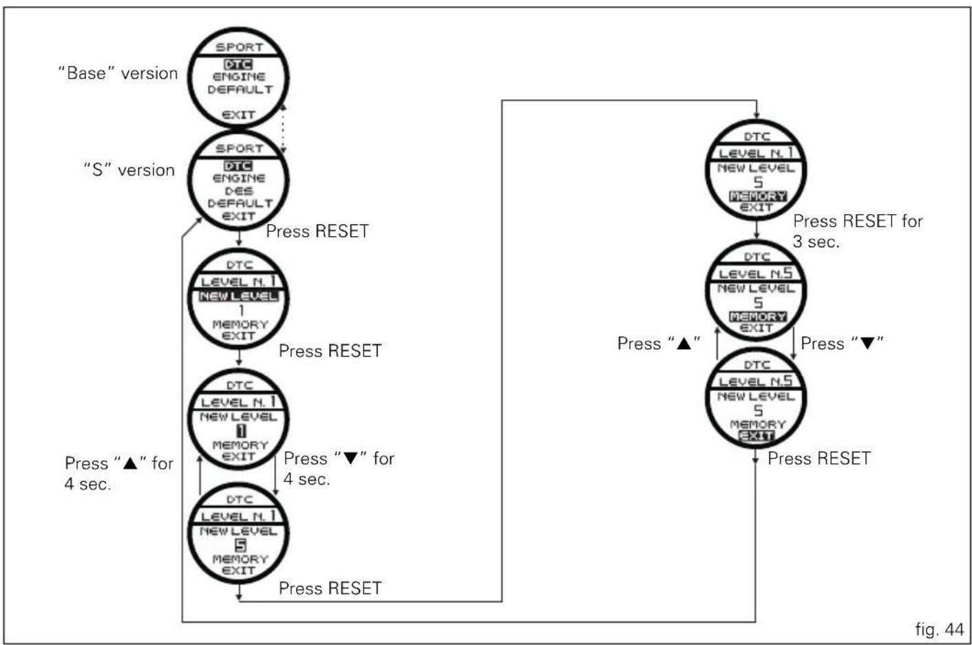
To display the function, enter the "Setting" menu page 46 and access the "SET UP" page. Use buttons (1, fig. 7) "▲" and (2, fig. 7) "▼" to select the riding style to be changed and press the reset button (14, fig. 4) to access the "DTC" function.
When accessing the function, the set DTC level "LEVEL N" will appear at the top of the circular display (B, fig. 6).
The intervention levels range from "1" to "8"; the higher the number, the greater the intervention of the Traction Control system.
To change the DTC intervention level, use buttons (1, fig. 7)
“▲” and (2, fig. 7) “▼” to select the “NEW LEVEL” indication and press the reset button (14, fig. 4).
The number to be set is shown on the display; buttons (1, fig. 7) “▲” and (2, fig. 7) “▼” can increase or decrease the number; press the reset button (14, fig. 4) to confirm the new level.
At this point, store the new setting by pressing the reset button (14, fig. 4) with "MEMORY" displayed.
The upper indication "LEVEL N.2" will be updated to confirm that the new setting was "received" and stored.
To exit the function, select "EXIT" and press the reset button (14, fig. 4).
The DTC intervention increases, passing from level 1 to level 8.
The following table indicates the most suitable level of DTC intervention for the various riding types as well as the default
settings in the "Riding Styles" that can be selected by the rider:
| DTC LEVEL | RIDING TYPE | USE DEFAULT? | |
| 1 ENDUROProfessional | Off-road for very expert riders. It permits elevated rear wheel spin. It does not intervene in time on asphalt. | NO | |
| 2 ENDURO Off-road | for less experienced riders. Does not intervene in time on asphalt. | It is the default level for the “ENDURO” Riding Style | |
| 3 TRACK Track for very expert riders. Permits sliding sideways | NO | ||
| 4 SPORT Sporty driving on a road or track | It is the default level for the “SPORT” Riding Style | ||
| 5 TOURING Normal riding It is the | default level for the “TOURING” Riding Style | ||
| 6 URBAN “Very safe” riding together with the use of an 100HP ENGINE (maximum power 100 HP) | It is the default level for the “URBAN” Riding Style | ||
| 7 | R | A I N | W |
| 8 HEAVY RAIN Wet road and slippery asphalt | NO | ||
flowchart
graph TD
    A[""Base" version"] --> B[""S" version"]
    B --> C["Press RESET"]
    C --> D["DTC LEVEL N.1 NEW LEVEL 1 MEMORY EXIT"]
    D --> E["Press RESET"]
    E --> F["DTC LEVEL N.1 NEW LEVEL 2 MEMORY EXIT"]
    F --> G["Press "▲" for 4 sec."]
    G --> H["Press RESET"]
    H --> I["Press RESET for 3 sec."]
    I --> J["DTC LEVEL N.5 NEW LEVEL 5 MEMORY EXIT"]
    J --> K["Press "▲"]
    K --> L["Press RESET"]
    L --> M["Press RESET"]
    M --> N["Press RESET"]
    N --> O["Press RESET"]
    O --> P["Press RESET"]


Tips on how to select the sensitivity level

Warning
The 8 level settings of the DTC were calibrated using tyres of the same make, model and size as those originally fitted to the motorcycle.
The use of tyres of different size to the original tyres may alter the operating characteristics of the system.
In the case of minor differences, such as for example, tyres of a different make and/or model than the original, but with the same dimensions (rear = 190/55-17; front = 120/70-17), it may be sufficient to simply select the most suitable level setting from those available to restore optimal system operation.
If tyres of a different size class are used or if the tyre dimensions differ significantly from the original tyres, it may be that the system operation is affected to the point where none of the 8 available level settings will give satisfactory results.
In this case is it is advisable to deactivate the traction control system.
If level 8 is selected, the DTC control unit will kick in at the slightest hint that the rear wheel is starting to spin.
Between level 8 and level 1 there are a further 6 intermediate levels. The level of DTC intervention decreases in equal steps from level 8 to level 1.
When levels 1, 2 or 3 is selected the DTC control unit will allow the rear wheel to spin and also slide sideways on exiting a corner; we recommend that this setting is only used by very experienced riders.
The choice of the correct level depends on 3 main variables:
1) The grip (type of tyre, amount of tyre wear, the road/track surface, weather conditions, etc.)
2) The characteristics of the path/circuit (bends all taken at similar speeds or at very different speeds)
3) The riding style (whether the rider has a "smooth" or a "rough" style)
The relation of the DTC intervention level to grip conditions: The choice of level setting depends greatly on the grip conditions of the track/circuit (see below, tips for use on the track and on the road).
The relation of the DTC intervention level to the circuit characteristics:
If all the corners on the track/circuit can be taken at a similar speed, it will be easier to find an intervention level that is satisfactory for every bend; on the other hand, if the track has, for example, one corner that is much slower than all the others, it will necessary to find a compromise level (on the slow corner the DTC will tend to control more than on the faster corners).
The relation of the DTC intervention level to riding style: The DTC will tend to kick in more with a “smooth” riding style, where the bike is leaned over further, rather than with a “rough” style, where the bike is straightened up as quickly as possible when exiting a turn.
Tips for use on the track
We recommend level 8 be used for a couple of full laps (to allow the tyres to warm up) in order to get used to the system. Then try levels 7, 6, etc., in succession until you identify the DTC intervention level that suits you best (always try each level for at least two laps to allow the tyres to warm up).
Once you have found a satisfactory setting for all the corners except one or two slow ones, where the system tends to kick in and control too much, you can try to modify your riding style slightly to a more “rough” approach to cornering i.e. straighten up more rapidly on exiting the corner, instead of immediately trying a different level setting.
Tips for use on the road
Activate the DTC, select level 8 and ride the motorcycle in your usual style; if the level of DTC intervention seems excessive, try reducing the setting to levels 7, 6, etc., until you find the level that suits you best. If changes in the grip conditions and/or circuit characteristics and/or your riding style, and the level setting is no longer suitable, switch to the next level up or down and proceed as described above to determine the best setting (e.g. if with level 7 the DTC intervention seems excessive, switch to level 6; alternatively, if on level 7 you cannot perceive any DTC intervention, switch to level 8).

E
ENGINE setting function (Engine Power Control)
This function customises engine power and output.
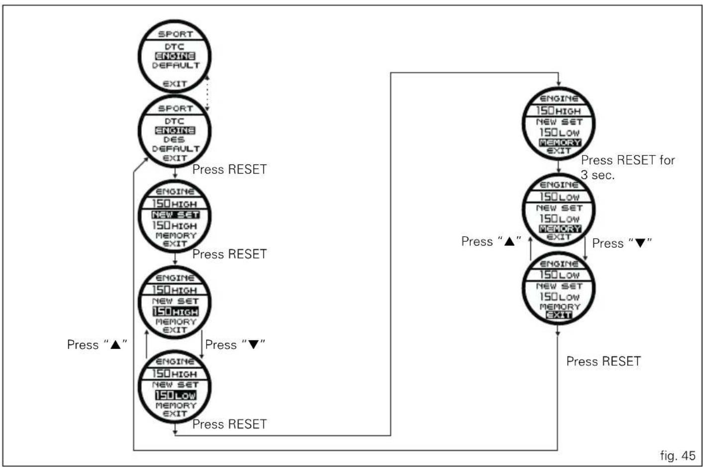
To display the function, enter the "Setting" menu page 46 and access the "SET UP" page. Use buttons (1, fig. 7) "▲" and (2, fig. 7) "▼" to select the riding style to be changed and press the reset button (14, fig. 4) to access the "ENGINE" function.
When accessing the function, the engine setting (150 HIGH, 150 LOW or 100 HP) appears at the top of the circular display (B, fig. 6).
To change the engine "power", use buttons (1, fig. 7) "▲" and (2, fig. 7) "▼" to select the "NEW SET" indication and press the reset button (14, fig. 4).
Use the buttons (1, fig. 7) “▲” and (2, fig. 7) “▼” to select one of the 3 selections (150 HIGH, 150 LOW or 100 HP); press the reset button (14, fig. 4) to confirm the new level.
At this point, store the new setting by pressing the reset button (14, fig. 4) for 3 seconds with "MEMORY" displayed. The upper indication will be updated to confirm that the new setting was "received" and stored.
To exit the function, select "EXIT" and press the reset button (14, fig. 4).
flowchart
graph TD
    A["SPORT DTC ENGINE DEFAULT EXIT"] --> B["SPORT DTC ENGINE DES DEFAULT EXIT"]
    B --> C["ENGINE 150HIGH NEW SET 150HIGH MEMORY EXIT"]
    C --> D["ENGINE 150HIGH NEW SET 150HIGH MEMORY EXIT"]
    D --> E["ENGINE 150HIGH NEW SET 150LOW MEMORY EXIT"]
    E --> F["ENGINE 150HIGH NEW SET 150LOW MEMORY EXIT"]
    F --> G["ENGINE 150HIGH NEW SET 150LOW MEMORY EXIT"]
    G --> H["ENGINE 150HIGH NEW SET 150LOW MEMORY EXIT"]
    H --> I["ENGINE 150HIGH NEW SET 150LOW MEMORY EXIT"]
    I --> J["ENGINE 150HIGH NEW SET 150LOW MEMORY EXIT"]
    J --> K["ENGINE 150HIGH NEW SET 150LOW MEMORY EXIT"]
    K --> L["ENGINE 150HIGH NEW SET 150LOW MEMORY EXIT"]
    L --> M["ENGINE 150HIGH NEW SET 150LOW MEMORY EXIT"]
    M --> N["ENGINE 150HIGH NEW SET 150LOW MEMORY EXIT"]
    N --> O["ENGINE 150HIGH NEW SET 150LOW MEMORY EXIT"]
    O --> P["ENGINE 150HIGH NEW SET 150LOW MEMORY EXIT"]
    P --> Q["ENGINE 150HIGH NEW SET 150LOW MEMORY EXIT"]
    Q --> R["ENGINE 150HIGH NEW SET 150LOW MEMORY EXIT"]
    R --> S["ENGINE 150HIGH NEW SET 150LOW MEMORY EXIT"]
    S --> T["ENGINE 150HIGH NEW SET 150LOW MEMORY EXIT"]
    T --> U["ENGINE 150HIGH NEW SET 150LOW MEMORY EXIT"]
    U --> V["ENGINE 150HIGH NEW SET 150LOW MEMORY EXIT"]
    V --> W["ENGINE 150HIGH NEW SET 150LOW MEMORY EXIT"]
    W --> X["ENGINE 150HIGH NEW SET 150LOW MEMORY EXIT"]
    X --> Y["ENGINE 150HIGH NEW SET 150LOW MEMORY EXIT"]
    Y --> Z["ENGINE 150HIGH NEW SET 150LOW MEMORY EXIT"]
    Z --> AA["ENGINE 150HIGH NEW SET 150LOW MEMORY EXIT"]
    AA --> AB["ENGINE 150HIGH NEW SET 150LOW MEMORY EXIT"]
    AB --> AC["ENGINE 150HIGH NEW SET 150LOW MEMORY EXIT"]
    AC --> AD["ENGINE 150HIGH NEW SET 150LOW MEMORY EXIT"]
    AD --> AE["ENGINE 150HIGH NEW SET 150LOW MEMORY EXIT"]
    AE --> AF["ENGINE 150HIGH NEW SET 150LOW MEMORY EXIT"]
    AF --> AG["ENGINE 150HIGH NEW SET 150LOW MEMORY EXIT"]
    AG --> AH["ENGINE 150HIGH NEW SET 150LOW MEMORY EXIT"]
    AH --> AI["ENGINE 150HIGH NEW SET 150LOW MEMORY EXIT"]
    AI --> AJ["ENGINE 150HIGH NEW SET 150LOW MEMORY EXIT"]
    AJ --> AK["ENGINE 150HIGH NEW SET 150LOW MEMORY EXIT"]
    AK --> AL["ENGINE 150HIGH NEW SET 150LOW MEMORY EXIT"]
    AL --> AM["ENGINE 150HIGH NEW SET 150LOW MEMORY EXIT"]
    AM --> AN["ENGINE 150HIGH NEW SET 150LOW MEMORY EXIT"]
    AN --> AO["ENGINE 150HIGH NEW SET 150LOW MEMORY EXIT"]
    AO --> AP["ENGINE 150HIGH NEW SET 150LOW MEMORY EXIT"]
    AP --> AQ["ENGINE 150HIGH NEW SET 150LOW MEMORY EXIT"]
    AQ --> AR["ENGINE 150HIGH NEW SET 150LOW MEMORY EXIT"]
    AR --> AS["ENGINE 150HIGH NEW SET 150LOW MEMORY EXIT"]
    AS --> AT["ENGINE 150HIGH NEW SET 150LOW MEMORY EXIT"]
    AT --> AU["ENGINE 150HIGH NEW SET 150LOW MEMORY EXIT"]
    AU --> AV["ENGINE 150HIGH NEW SET 150LOW MEMORY EXIT"]
    AV --> AW["ENGINE 150HIGH NEW SET 150LOW MEMORY EXIT"]
    AW --> AX["ENGINE 150HIGH NEW SET 150LOW MEMORY EXIT"]
    AX --> AY["ENGINE 150HIGH NEW SET 150LOW MEMORY EXIT"]
    AY --> AZ["ENGINE 150HIGH NEW SET 150LOW MEMORY EXIT"]
    AZ --> BA["ENGINE 150HIGH NEW SET 150LOW MEMORY EXIT"]
    BA --> BB["ENGINE 150HIGH NEW SET 150LOW MEMORY EXIT"]
    BB --> BC["ENGINE 150HIGH NEW SET 150LOW MEMORY EXIT"]
    BC --> BD["ENGINE 150HIGH NEW SET 150LOW MEMORY EXIT"]
    BD --> BE["ENGINE 150HIGH NEW SET 150LOW MEMORY EXIT"]
    BE --> BF["ENGINE 150HIGH NEW SET 150LOW MEMORY EXIT"]
    BF --> BG["ENGINE 150HIGH NEW SET 150LOW MEMORY EXIT"]
    BG --> BH["ENGINE 150HIGH NEW SET 150LOW MEMORY EXIT"]
    BH --> BI["ENGINE 150HIGH NEW SET 150LOW MEMORY EXIT"]
    BI --> BJ["ENGINE 150HIGH NEW SET 150LOW MEMORY EXIT"]
    BJ --> BK["ENGINE 150HIGH NEW SET 150LOW MEMORY EXIT"]
    BK --> BL["ENGINE 150HIGH NEW SET 150LOW MEMORY EXIT"]
    BL --> BM["ENGINE 150HIGH NEW SET 150LOW MEMORY EXIT"]
    BM --> BN["ENGINE 150HIGH NEW SET 150LOW MEMORY EXIT"]
    BN --> BO["ENGINE 150HIGH NEW SET 150LOW MEMORY EXIT"]
    BO --> BP["ENGINE 150HIGH NEW SET 150LOW MEMORY EXIT"]
    BP --> BQ["ENGINE 150HIGH NEW SET 150LOW MEMORY EXIT"]
    BQ --> BR["ENGINE 150HIGH NEW SET 150LOW MEMORY EXIT"]
    BR --> BS["ENGINE 150HIGH NEW SET 150LOW MEMORY EXIT"]
    BS --> BT["ENGINE 150HIGH NEW SET 150LOW MEMORY EXIT"]
    BT --> BU["ENGINE 150HIGH NEW SET 150LOW MEMORY EXIT"]
    BU --> BV["ENGINE 150HIGH NEW SET 150LOW MEMORY EXIT"]
    BV --> BW["ENGINE 150HIGH NEW SET 150LOW MEMORY EXIT"]
    BW --> BX["ENGINE 150HIGH NEW SET 150LOW MEMORY EXIT"]
    BX --> BY["ENGINE 150HIGH NEW SET 150LOW MEMORY EXIT"]
    BY --> BZ["ENGINE 150HIGH NEW SET 150LOW MEMORY EXIT"]
    BZ --> CA["ENGINE 150HIGH NEW SET 150LOW MEMORY EXIT"]
    CA --> CB["ENGINE 150HIGH NEW SET 150LOW MEMORY EXIT"]
    CB --> CC["ENGINE 150HIGH NEW SET 150LOW MEMORY EXIT"]
    CC --> CD["ENGINE 150HIGH NEW SET 150LOW MEMORY EXIT"]
    CD --> CE["ENGINE 150HIGH NEW SET 150LOW MEMORY EXIT"]
    CE --> CF["ENGINE 150HIGH NEW SET 150LOW MEMORY EXIT"]
    CF --> CG["ENGINE 150HIGH NEW SET 150LOW MEMORY EXIT"]
    CG --> CH["ENGINE 150HIGH NEW SET 150LOW MEMORY EXIT"]
    CH --> CI["ENGINE 150HIGH NEW SET 150LOW MEMORY EXIT"]
    CI --> CJ["ENGINE 150HIGH NEW SET 150LOW MEMORY EXIT"]
    CJ --> CK["ENGINE 150HIGH NEW SET 150LOW MEMORY EXIT"]
    CK --> CL


DES setting function (Ducati Electronic Suspension)
Available in the "S" version only.
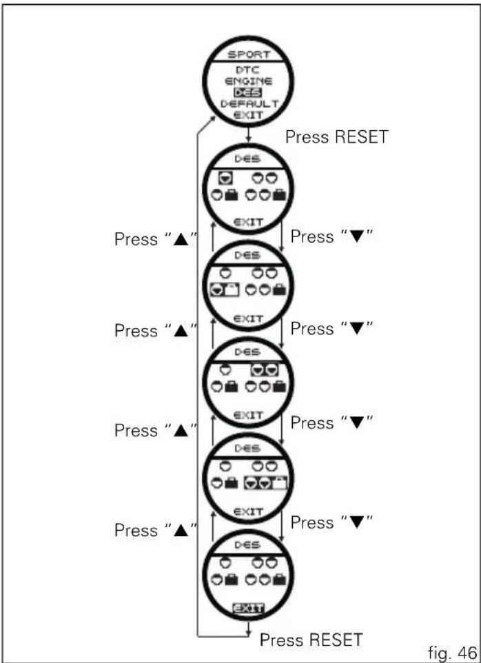
To display the function, enter the "Setting" menu page 46 and access the "SET UP" page. Use buttons (1, fig. 7) "▲" and (2, fig. 7) "▼" to select the riding style to be changed and press the reset button (14, fig. 4) to access the "DES" function.
When accessing the function, the four different types of setup appear on the circular display (B, fig. 6) (fig. 28).
Use buttons (1, fig. 7) "▲" and (2, fig. 7) "▼" to select the setup to customise and press the reset button (14, fig. 4).
flowchart
graph TD
    A["SPORT\nDTC\nENGINE\nDES\nDEFAULT\nEXIT"] -->|Press RESET| B["D-ES\nEXIT"]
    B -->|Press “▼”| C["D-ES\nEXIT"]
    C -->|Press “▼”| D["D-ES\nEXIT"]
    D -->|Press “▼”| E["D-ES\nEXIT"]
    E -->|Press “▼”| F["D-ES\nEXIT"]
    F -->|Press “▼”| G["D-ES\nEXIT"]
    G -->|Press “▼”| H["D-ES\nEXIT"]
    H -->|Press RESET| I["Exit"]
    style A fill:#f9f,stroke:#333
    style I fill:#f9f,stroke:#333
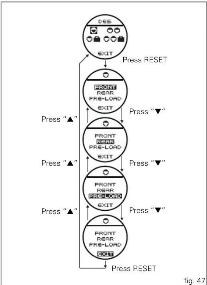
The three parameters to change appear on the circular display (B, fig. 6):
- FRONT: adjustment of the front shock absorber rebound and compression;
- REAR: adjustment of the rear shock absorber rebound and compression;
- PRE-LOAD: adjustment of the rear shock absorber spring preload.
Use buttons (1, fig. 7) "▲" and (2, fig. 7) "▼" to select the parameter to change and press the reset button (14, fig. 4).
flowchart
graph TD
    A["DES\nEXIT"] --> B["FRONT\nREAR\nPRE-LOAD\nEXIT"]
    B --> C["FRONT\nREAR\nPRE-LOAD\nEXIT"]
    C --> D["FRONT\nREAR\nPRE-LOAD\nEXIT"]
    D --> E["FRONT\nREAR\nPRE-LOAD\nEXIT"]
    E --> F["FRONT\nREAR\nPRE-LOAD\nEXIT"]
    F --> G["Press RESET"]
    B --> H["Press "▲""]
    C --> I["Press "▼""]
    D --> J["Press "▲""]
    E --> K["Press "▼""]
    F --> L["Press "▲""]
    G --> M["Press RESET"]


"FRONT" adjustment
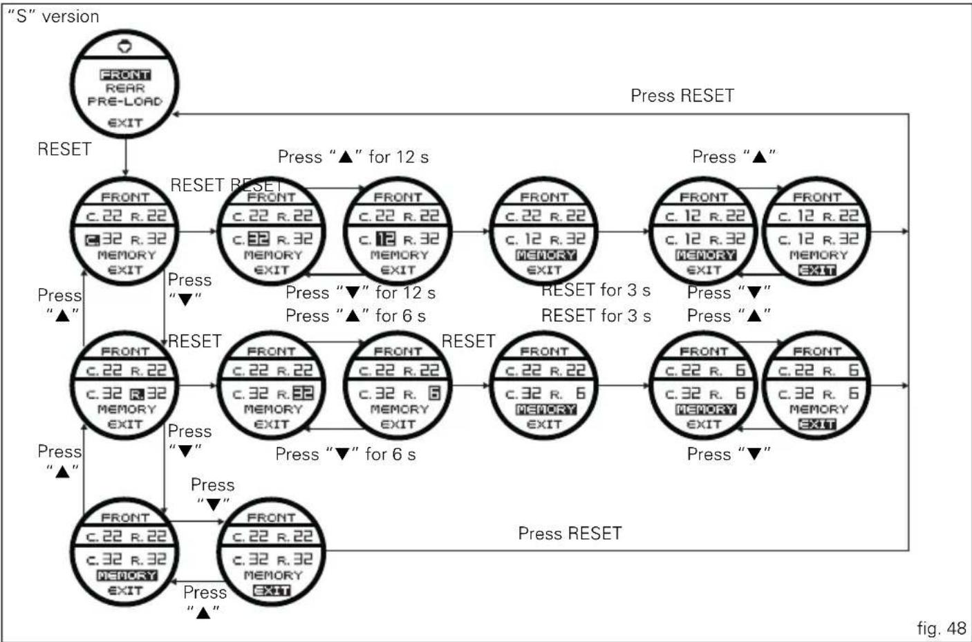
- the top of the circular display (B, fig. 6) will show the set compression [C.] and rebound [R.];
- use buttons (1, fig. 7) "▲" and (2, fig. 7) "▼" to select the parameter to change and press the reset button (14, fig. 4);
- the number to change appears on the circular display (B);
- buttons (1, fig. 7) "▲" and (2, fig. 7) "▼" can increase or decrease the number (between 1 and 32);
- press the reset button (14, fig. 4) to confirm the new level.

Note
Increasing the set value "decreases" the hydraulic
"braking"; decreasing the value "increases" the hydraulic "braking" of the shock absorber.
At this point, store the new setting by pressing the reset button (14, fig. 4) for 3 seconds with "MEMORY" displayed. The upper indication [C.] or [R.] will be updated to confirm that the new setting was "received" and stored. To exit the function, select "EXIT" and press the reset button (14, fig. 4).
flowchart
graph TD
    A[""S" version"] --> B["RESET"]
    B --> C["FRONT c.22 R.22 c.32 R.32 MEMORY EXIT"]
    C --> D["RESET RESET"]
    D --> E["FRONT c.22 R.22 c.32 R.32 MEMORY EXIT"]
    E --> F["FRONT c.22 R.22 c.12 R.32 MEMORY EXIT"]
    F --> G["RESET for 3 s RESET for 3 s"]
    G --> H["FRONT c.12 R.22 c.12 R.32 MEMORY EXIT"]
    H --> I["FRONT c.12 R.22 c.12 R.32 MEMORY EXIT"]
    I --> J["Press "▲" for 12 s"]
    J --> K["FRONT c.22 R.22 c.32 R.32 MEMORY EXIT"]
    K --> L["RESET RESET"]
    L --> M["FRONT c.22 R.22 c.32 R.32 MEMORY EXIT"]
    M --> N["FRONT c.22 R.22 c.32 R.6 MEMORY EXIT"]
    N --> O["RESET for 6 s"]
    O --> P["FRONT c.22 R.22 c.32 R.6 MEMORY EXIT"]
    P --> Q["FRONT c.22 R.6 c.32 R.6 MEMORY EXIT"]
    Q --> R["Press "▼" for 6 s"]
    R --> S["FRONT c.22 R.6 c.32 R.6 MEMORY EXIT"]
    S --> T["FRONT c.22 R.6 c.32 R.6 MEMORY EXIT"]
    T --> U["Press "▼" for 6 s"]
    U --> V["FRONT c.22 R.6 c.32 R.6 MEMORY EXIT"]
    V --> W["Press RESET"]
    W --> X["FRONT c.22 R.6 c.32 R.6 MEMORY EXIT"]
    X --> Y["Press "▲" for 12 s"]
    Y --> Z["FRONT c.22 R.6 c.32 R.6 MEMORY EXIT"]
    Z --> AA["Press RESET"]
    AA --> AB["FRONT c.22 R.6 c.32 R.6 MEMORY EXIT"]
    AB --> AC["Press RESET"]


"REAR" adjustment
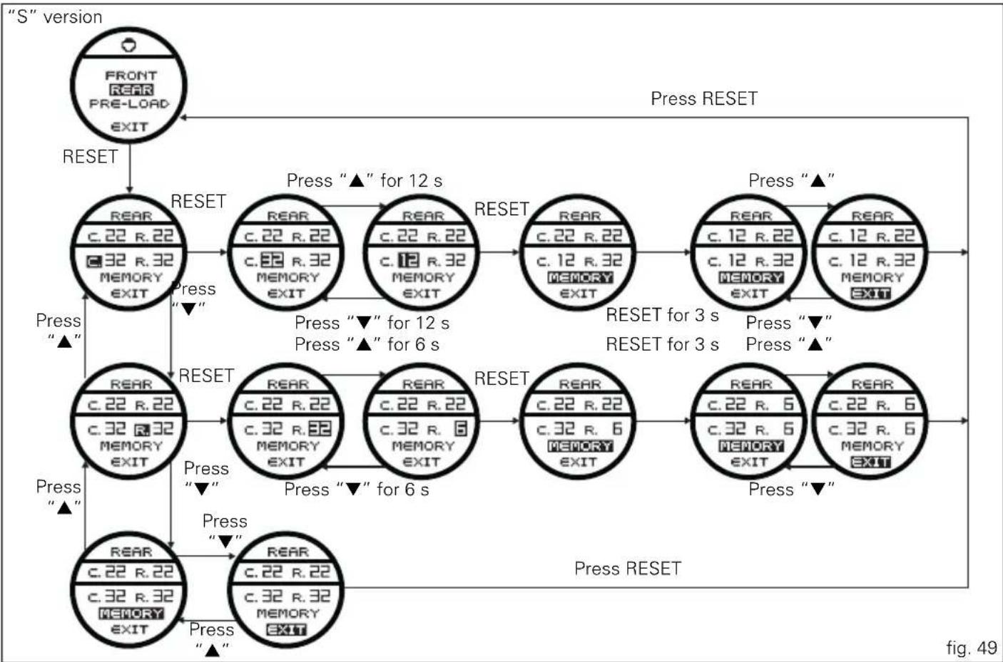
- the top of the circular display (B, fig. 6) will show the set compression [C.] and rebound [R.];
- use buttons (1, fig. 7) "▲" and (2, fig. 7) "▼" to select the parameter to change and press the reset button (14, fig. 4);
- the number to be changed is shown on the display;
- buttons (1, fig. 7) "▲" and (2, fig. 7) "▼" can increase or decrease the number (between 1 and 32);
- press the reset button (14, fig. 4) to confirm the new level.

Note
Increasing the set value "decreases" the hydraulic
"braking"; decreasing the value "increases" the hydraulic "braking" of the shock absorber.
At this point, store the new setting by pressing the reset button (14, fig. 4) for 3 seconds with "MEMORY" displayed. The upper indication [C.] or [R.] will be updated to confirm that the new setting was "received" and stored. To exit the function, select "EXIT" and press the reset button (14, fig. 4).
flowchart
graph TD
    A[""S" version"] --> B["FRONT REAR PRE-LOAD EXIT"]
    B --> C["RESET"]
    C --> D["REAR C.22 R.22 C.32 R.32 MEMORY EXIT"]
    D --> E["Press "▲" for 12 s"]
    E --> F["REAR C.22 R.22 C.32 R.32 MEMORY EXIT"]
    F --> G["Press "▼" for 6 s"]
    G --> H["REAR C.22 R.22 C.12 R.32 MEMORY EXIT"]
    H --> I["Press "▲" for 12 s"]
    I --> J["REAR C.12 R.22 C.12 R.32 MEMORY EXIT"]
    J --> K["Press "▲" for 3 s"]
    K --> L["REAR C.12 R.22 C.12 R.32 MEMORY EXIT"]
    L --> M["Press "▼" for 3 s"]
    M --> N["REAR C.22 R.6 C.32 R.6 MEMORY EXIT"]
    N --> O["Press "▼" for 6 s"]
    O --> P["REAR C.22 R.6 C.32 R.6 MEMORY EXIT"]
    P --> Q["Press RESET"]
    Q --> R["REAR C.22 R.6 C.32 R.6 MEMORY EXIT"]
    R --> S["Press RESET"]
    S --> T["REAR C.22 R.6 C.32 R.6 MEMORY EXIT"]
    T --> U["Press RESET"]
    U --> V["REAR C.22 R.6 C.32 R.6 MEMORY EXIT"]
    V --> W["Press RESET"]


"PRE-LOAD" adjustment
- the top of the circular display (B, fig. 6) will show the "preload" and a bargraph indicating the set value;
- use buttons (1, fig. 7) "▲" and (2, fig. 7) "▼" to select "NEW SET" and press the reset button (14, fig. 4);
- the number to be changed is shown on the display;
- buttons (1, fig. 7) “▲” and (2, fig. 7) “▼” can increase or decrease the number (between 1 and 16);
- press the reset button (14, fig. 4) to confirm the new level.

Note
Increasing the set value "stiffens" the rear shock absorber; decreasing the value "softens" the rear shock absorber.
At this point, store the new setting by pressing the reset button (14, fig. 4) for 3 seconds with "MEMORY" displayed. The upper indication and the bargraph will be updated to confirm that the new setting was "received" and stored. To exit the function, select "EXIT" and press the reset button (14, fig. 4).
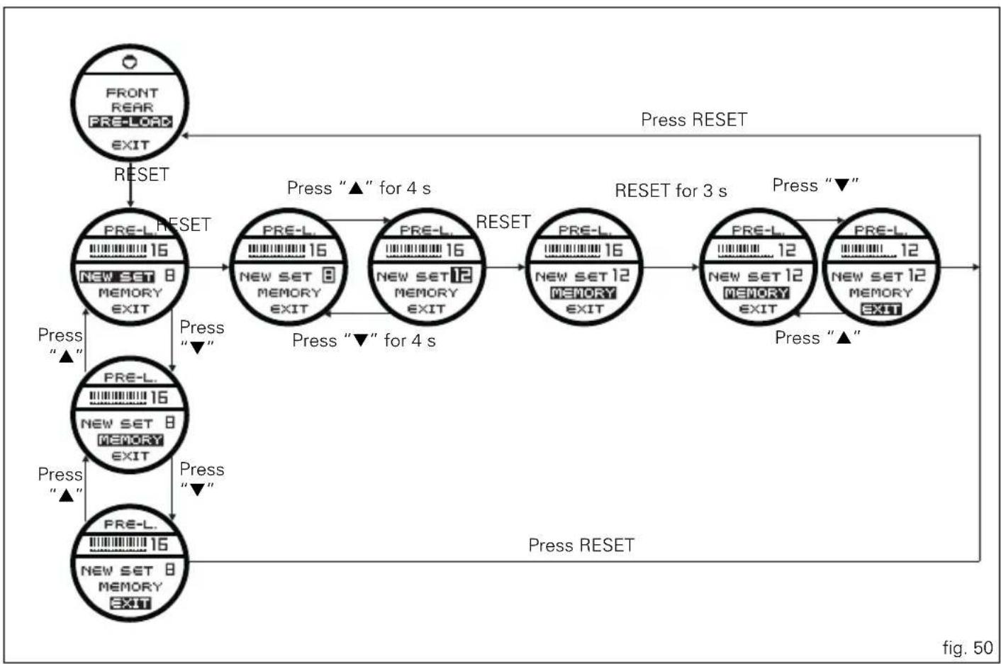
flowchart
graph TD
    A["FRONT REAR PRE-LOAD EXIT"] --> B["RESET"]
    B --> C["PRE-L RESET"]
    C --> D["PRE-L 16 NEW SET 8 MEMORY EXIT"]
    D --> E["Press "▲" for 4 s"]
    E --> F["PRE-L 16 NEW SET 8 MEMORY EXIT"]
    F --> G["Press "▼" for 4 s"]
    G --> H["PRE-L 16 NEW SET 12 MEMORY EXIT"]
    H --> I["Press "▼" for 4 s"]
    I --> J["PRE-L 16 NEW SET 12 MEMORY EXIT"]
    J --> K["Press "▲" for 3 s"]
    K --> L["PRE-L 12 NEW SET 12 MEMORY EXIT"]
    L --> M["Press "▼" for 3 s"]
    M --> N["PRE-L 12 NEW SET 12 MEMORY EXIT"]
    N --> O["Press "▲" for 3 s"]
    O --> P["PRE-L 12 NEW SET 12 MEMORY EXIT"]
    P --> Q["Press RESET"]
    Q --> R["POST RESET"]
    R --> S["POST RESET"]


DEFAULT function (Resetting Ducati default parameters)
This function resets the parameters set by Ducati for each riding style.
To display the function, enter the "setting" menu page 46 and access the "SET UP" page. Use the buttons (1, fig. 7) "▲" and (2, fig. 7) "▼" to select the riding style for which you want to restore the settings and access the "DEFAULT" function.
When accessing the function "DEFAULT PARAMETER?" will appear on the circular display (B, fig. 6); To reset the parameters, select "YES" and press the reset button (14, fig. 4).
For the parameter reset, approx. 15 seconds are needed during which "WAIT..." will appear on the display; at the end of the procedure, "DEFAULT OK" will appear on the circular display (B, fig. 6) to indicate that the parameters were reset.

Important
This procedure restores the parameters for all riding
styles.
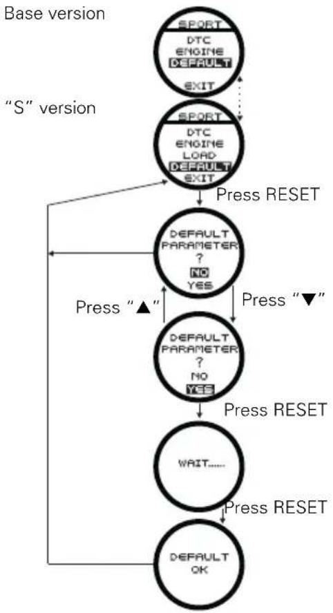
flowchart
graph TD
    A["Base version"] --> B[""S" version"]
    B --> C["SPORT DTC ENGINE DEFAULT EXIT"]
    C --> D["SPORT DTC ENGINE LOAD DEFAULT EXIT"]
    D --> E["Press RESET"]
    E --> F["DEFAULT PARAMETER ? NO YES"]
    F --> G["Press "▲""]
    G --> H["DEFAULT PARAMETER ? NO YES"]
    H --> I["Press RESET"]
    I --> J["WAIT......"]
    J --> K["Press RESET"]
    K --> L["DEFAULT OK"]
    L --> M["Press RESET"]
fig. 51

Instrument panel backlighting adjustment function
This function adjusts the instrument panel backlighting intensity.
To display the function, enter the "setting" menu page 46 and access the "B. LIGHT" page.
The information will be displayed as follows:
- the arrows indicate the adjustment currently in use;
- use buttons (1, fig. 7) "▲" and (2, fig. 7) "▼" to select the new adjustment;
- to store the new adjustment press the reset button (14, fig. 4); the arrows will move to the new stored condition.
To exit, select "EXIT" and press the reset button (14, fig. 4).
"MAX" adjustment: storing this condition, the backlighting is at maximum brightness;
"MID" adjustment: storing this condition, the backlighting is reduced approximately 30% relative to maximum brightness;
"MIN" adjustment: storing this condition, the backlighting is reduced approximately 70% relative to maximum brightness;

Note
In the event of an interruption of the power supply from the battery, when power is restored at the next Key-On, the backlighting will always be set by default to maximum brightness.
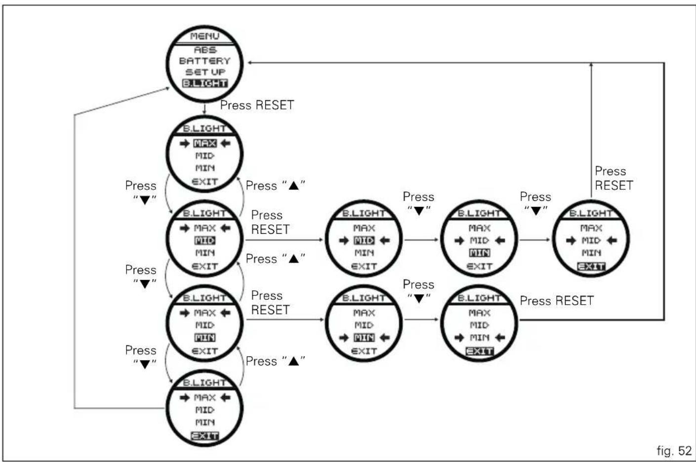
flowchart
graph TD
    A["MENU ABS BATTERY SETUP BLIGHT"] -->|Press RESET| B["B.LIGHT MAX MID MIN EXIT"]
    B -->|Press “▲”| C["B.LIGHT MAX MID MIN EXIT"]
    C -->|Press RESET| D["B.LIGHT MAX MID MIN EXIT"]
    D -->|Press “▼”| E["B.LIGHT MAX MID MIN EXIT"]
    E -->|Press “▲”| F["B.LIGHT MAX MID MIN EXIT"]
    F -->|Press RESET| G["B.LIGHT MAX MID MIN EXIT"]
    G -->|Press “▼”| H["B.LIGHT MAX MID MIN EXIT"]
    H -->|Press RESET| I["B.LIGHT MAX MID MIN EXIT"]
    I -->|Press RESET| J["B.LIGHT MAX MID MIN EXIT"]
    J -->|Press RESET| K["Menu ABS BATTERY SETUP BLIGHT"]
    style A fill:#f9f,stroke:#333
    style K fill:#f9f,stroke:#333

E
LAP Activation/Deactivation function (lap time)
This function activates and deactivates the LAP function (lap time).
To display the function, enter the "setting" menu page 46 and access the "LAP" page.
In the next display, press the reset button (14. fig. 4) showing "ON / OFF".
The information will be displayed as follows:
- the arrows indicate the setting currently in use;
- use buttons (1, fig. 7) "▲" and (2, fig. 7) "▼" to select the new setting;
- to store the new setting press the reset button (14, fig.
4); the arrows will move to the new stored condition.
To exit, select "EXIT" and press the reset button (14, fig. 4). Storing the "OFF" condition disables the LAP function; Storing the "ON" condition enables the LAP function (see LAP registration operation).

Note
When the "LAP" function is active, the flash button
(13. fig. 4) takes on the dual function of high beam headlight "flash" and lap time Start / Stop.
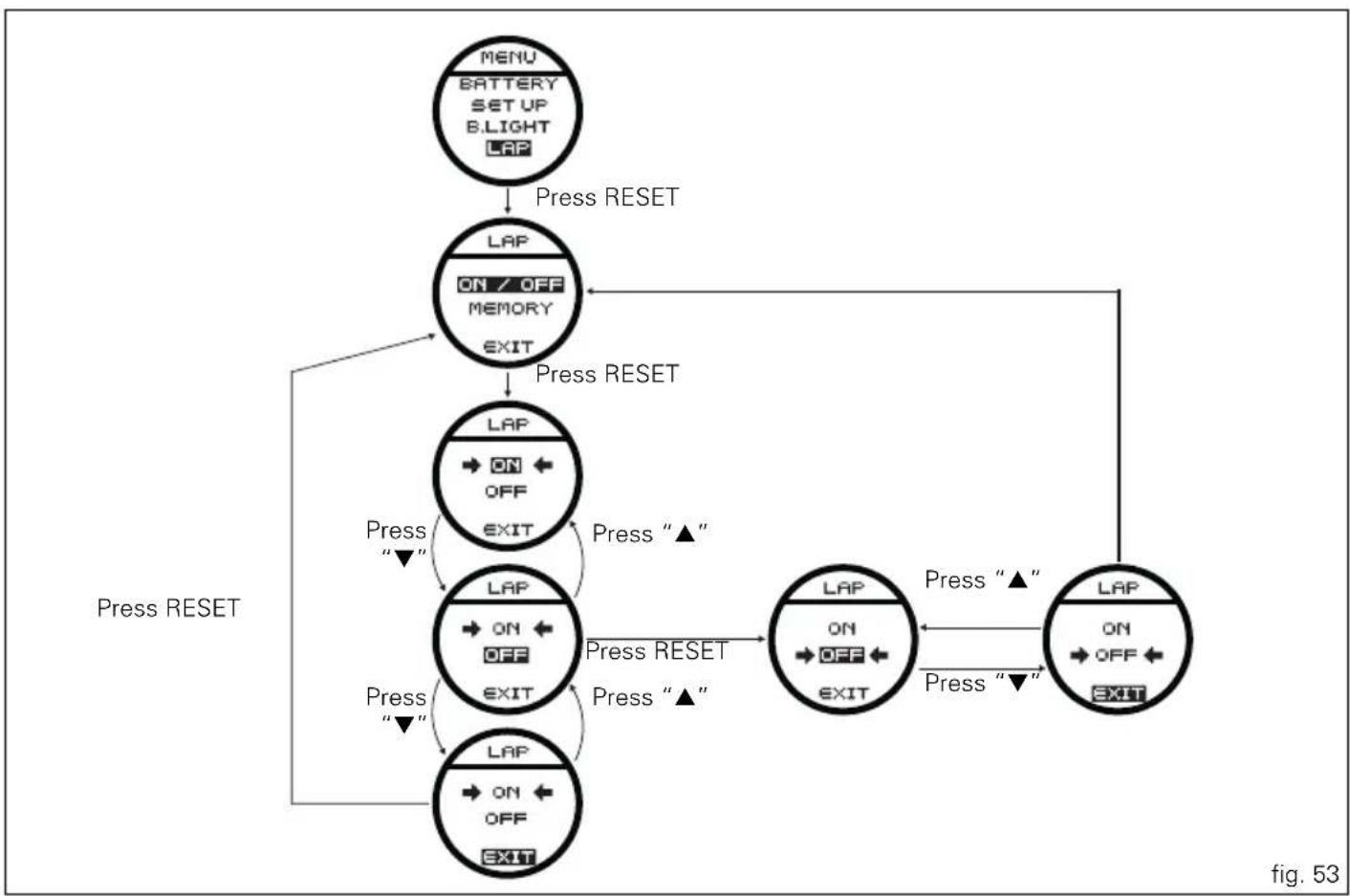
flowchart
graph TD
    A["MENU BATTERY SETUP BLIGHT LAP"] -->|Press RESET| B["LAP ON/OFF MEMORY EXIT"]
    B -->|Press RESET| C["LAP ON/OFF EXIT"]
    C -->|Press "▲"| D["LAP ON/OFF EXIT"]
    D -->|Press "▲"| E["LAP ON/OFF EXIT"]
    E -->|Press "▼"| F["LAP ON/OFF EXIT"]
    F -->|Press "▼"| G["LAP ON/OFF EXIT"]
    G --> H["Press RESET"]
    style A fill:#f9f,stroke:#333
    style B fill:#ccf,stroke:#333
    style C fill:#cfc,stroke:#333
    style D fill:#fcc,stroke:#333
    style E fill:#cff,stroke:#333
    style F fill:#ffc,stroke:#333
    style G fill:#cfc,stroke:#333
    style H fill:#fcc,stroke:#333

E
LAP registration function
This function describes the "LAP" time registration.
If the function is activated (see "LAP activation/deactivation description"), the lap time can be registered as follows:
- the first time the flash is pressed (13, fig. 4) starts the "lap timer" for the first lap and the instrument panel shows the "START LAP" indication on the circular display (B, fig. 6) for 4 seconds and then returns to the "previous" display;
- from this moment, each time that the flash is pressed (13, fig. 4) the circular display (B, fig. 6) automatically shows the lap time for 10 seconds and then returns to the “previous” display.
You can save a maximum of 30 laps in the memory.
If the memory is full, each time you press the flash button (13, fig. 4), the instrument panel will not store any more lap times and will show the flashing message "LAP MEMORY FULL" on the circular display (B, fig. 6) for 3 seconds until the times are reset.
When the LAP function is set disabled, the current "lap" is not stored.
If the LAP function is active and suddenly the motorcycle is suddenly turned off (Key-Off), the function will be automatically disabled (even if the lap timer was active, the current "lap" is not stored).
If the time is never “stopped”, it will roll over upon reaching 9 minutes, 59 seconds and 99 hundredths; the lap timer starts counting from 0 (zero) and will keep running until the function is disabled.
If however the LAP function is switched on and the memory has not been cleared, but fewer than 30 laps have been saved (e.g. 18 laps), the instrument panel will store any remaining laps until the memory is full (in this case, it will store an additional 12 laps).
This function only displays the times for the lap being registered; but other data are also saved (MAX speed, MAX rpm, rev limiter if reached) for viewing at a later date in the Lap Memory function (stored LAP display).
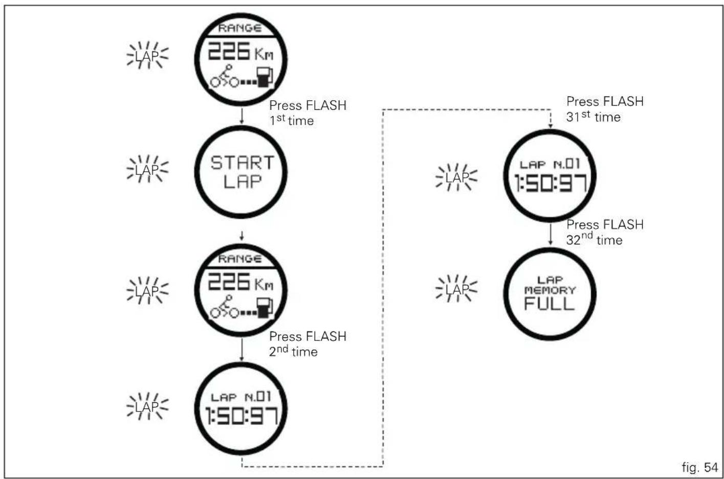
flowchart
graph TD
    A["RANGE 226 Km"] --> B["START LAP"]
    B --> C["RANGE 226 Km"]
    C --> D["LAP N.01 1:50:97"]
    D --> E["LAP N.01 1:50:97"]
    E --> F["LAP N.01 1:50:97"]
    F --> G["LAP N.01 1:50:97"]
    G --> H["LAP N.01 1:50:97"]
    H --> I["LAP N.01 1:50:97"]
    I --> J["LAP N.01 1:50:97"]
    J --> K["LAP N.01 1:50:97"]
    K --> L["LAP N.01 1:50:97"]
    L --> M["LAP N.01 1:50:97"]
    M --> N["LAP N.01 1:50:97"]
    N --> O["LAP N.01 1:50:97"]
    O --> P["LAP N.01 1:50:97"]
    P --> Q["LAP N.01 1:50:97"]
    Q --> R["LAP N.01 1:50:97"]
    R --> S["LAP N.01 1:50:97"]
    S --> T["LAP N.01 1:50:97"]
    T --> U["LAP N.01 1:50:97"]
    U --> V["LAP N.01 1:50:97"]
    V --> W["LAP N.01 1:50:97"]
    W --> X["LAP N.01 1:50:97"]
    X --> Y["LAP N.01 1:50:97"]
    Y --> Z["LAP N.01 1:50:97"]
    Z --> AA["LAP N.01 1:50:97"]
    AA --> AB["LAP N.01 1:50:97"]
    AB --> AC["LAP N.01 1:50:97"]
    AC --> AD["LAP N.01 1:50:97"]
    AD --> AE["LAP N.01 1:50:97"]
    AE --> AF["LAP N.01 1:50:97"]
    AF --> AG["LAP N.01 1:50:97"]
    AG --> AH["LAP N.01 1:50:97"]
    AH --> AI["LAP N.01 1:50:97"]
    AI --> AJ["LAP N.01 1:50:97"]
    AJ --> AK["LAP N.01 1:50:97"]
    AK --> AL["LAP N.01 1:50:97"]
    AL --> AM["LAP N.01 1:50:97"]
    AM --> AN["LAP N.01 1:50:97"]
    AN --> AO["LAP N.01 1:50:97"]
    AO --> AP["LAP N.01 1:50:97"]
    AP --> AQ["LAP N.01 1:50:97"]
    AQ --> AR["LAP N.01 1:50:97"]
    AR --> AS["LAP N.01 1:50:97"]
    AS --> AT["LAP N.01 1:50:97"]
    AT --> AU["LAP N.01 1:50:97"]
    AU --> AV["LAP N.01 1:50:97"]
    AV --> AW["LAP N.01 1:50:97"]
    AW --> AX["LAP N.01 1:50:97"]
    AX --> AY["LAP N.01 1:50:97"]
    AY --> AZ["LAP N.01 1:50:97"]
    AZ --> BA["LAP N.01 1:50:97"]
    BA --> BB["LAP N.01 1:50:97"]
    BB --> BC["LAP N.01 1:50:97"]
    BC --> BD["LAP N.01 1:50:97"]
    AD --> CE["Press FLASH 31st time"]
    AE --> CF["Press FLASH 32nd time"]
    AF --> CG["Press FLASH 32nd time"]
    AH --> CH["Press FLASH 32nd time"]
    AI --> CI["Press FLASH 32nd time"]
    AJ --> CJ["Press FLASH 32nd time"]
    AK --> CK["Press FLASH 32nd time"]
    AL --> CL["Press FLASH 32nd time"]
    AM --> CD["Press FLASH 32nd time"]
    AN --> DE["Press FLASH 32nd time"]
    AO --> DF["Press FLASH 32nd time"]
    AP --> DG["Press FLASH 32nd time"]
    AQ --> DH["Press FLASH 32nd time"]
    AE --> DI["Press FLASH 32nd time"]


Stored LAP display function
This function displays the stored LAPs.
To display the function, enter the "setting" menu page 46 and access the "LAP" page.
In the next display, press the reset button (14. fig. 4) showing "MEMORY".
The instrument panel displays the information as follows:
Circular display (B, fig. 6):
- the number of the displayed lap (ex: no.1);
- "NEXT" to display the next LAP;
- "RESET" to delete all the stored times.
To exit, select "EXIT" and press the reset button (14, fig. 4).
Main display (A, fig. 6):
- the time in the upper left (ex: 1:50:97);
- the maximum speed reached in the registered LAP to the upper right;
- the number of maximum RPMs reached in the registered lap at the bottom.

Note
The MAX stored speed is indicated on the main display
(A) (increased by 8%).
If the MAX speed reading exceeds 299 Km/h (186 mph)
while the information is stored, the speed that was reached is still displayed (example: 316 Km/h).
If there is no reading in the memory, the 30 times are shown, with the display showing "0.00.00", MAX rpm = 0 and MAX speed = 0.
If while registering the LAP the engine reaches the threshold that precedes the rev limiter or rev limiter threshold, the relative light "Over Rev" (9, fig. 3) will turn on when displaying the stored times.
To display other stored times, select "NEXT" and press the reset button (14, fig. 4); the next lap will be displayed each time the reset button (14, fig. 4) is pressed.
To delete all the stored times, select "RESET" and press the rest button (14, fig. 4) for 3 seconds.

Note
If the stored times are deleted while the LAP function
is active, it will be automatically deactivated.
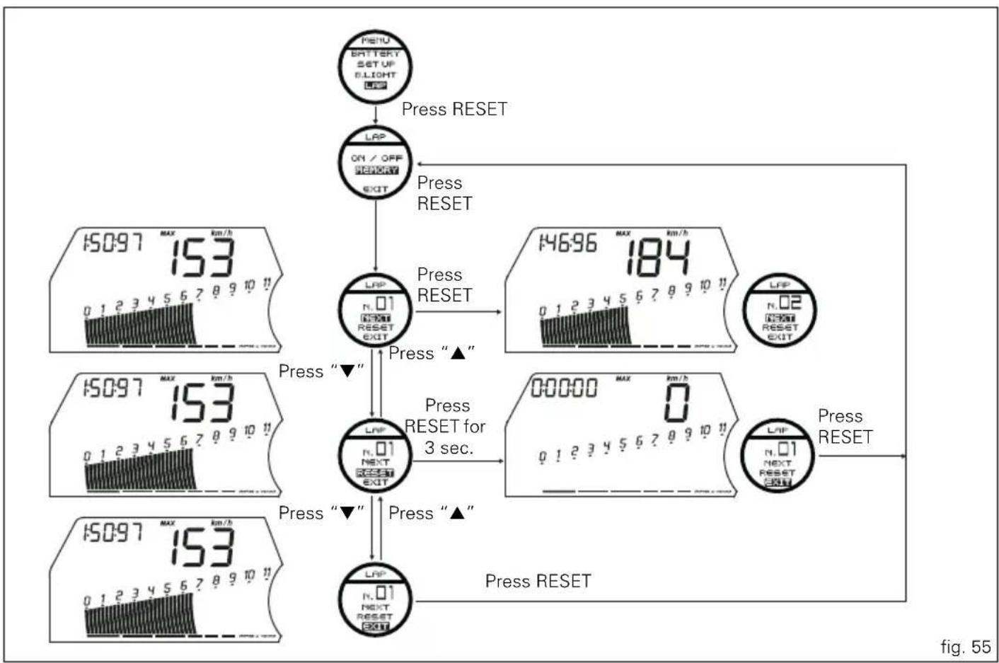
flowchart
graph TD
    A["PSIU BATTERY SET UP BLIGHT"] -->|Press RESET| B["LAP ON/OFF MEMORY EXIT"]
    B --> C["LAP N.01 NEXT RESET EXIT"]
    C -->|Press RESET| D["146:96 MAX 184"]
    D --> E["LFP N.02 NEXT EXIT"]
    E --> F["00:00:00 MAX 0"]
    F --> G["LAP N.01 NEXT EXIT"]
    G --> H["Press RESET"]
    H --> I["Press RESET"]
    I --> J["Press "▲""]
    J --> K["LAP N.01 NEXT EXIT"]
    K --> L["Press "▼""]
    L --> M["15:097 MAX 153"]
    M --> N["Press "▲""]
    N --> O["Press RESET"]
    O --> P["Press RESET"]
    P --> Q["Press RESET"]
    Q --> R["Press RESET"]


DTC (Ducati Traction Control) on/off function

Warning
DTC is a rider aid that can be used both on the track and pad.
The system is designed to make riding easier and to enhance safety, but in no way relieves the rider of the obligation to drive responsibly and to maintain a high standard of riding in order to avoid accidents, whether caused by his own errors or those of other road users, through making emergency manoeuvres, in accordance with the prescriptions of the road traffic code.
The rider must always be aware that active safety systems have a preventive function. The active elements help the rider control the motorcycle, making it as easy and safe to ride as possible. The presence of an active safety system should not encourage the rider to ride at speeds beyond the reasonable limits, in accordance with the road conditions, the laws of physics, good riding standards and the requirements of the road traffic code.
This function activates and deactivates the DTC (Ducati Traction Control).
To display the function, enter the "setting" menu page 46 and access the "DTC" page.
In the next display, press the reset button (14. fig. 4) showing "ON / OFF".
The information will be displayed as follows:
- the arrows indicate the setting currently in use;
- use buttons (1, fig. 7) “▲” and (2, fig. 7) “▼” to select the new setting;
- to store the new setting press the reset button (14, fig. 4); the arrows will move to the new stored condition.
To exit, select "EXIT" and press the reset button (14, fig. 4). Storing the "OFF" condition disables the Traction Control; Storing the "ON" condition enables the Traction Control.

Note
Deactivating the DTC automatically activates the previously described "warning" "DTC OFF". If a battery is cutoff, when the voltage is restored and at the next Key-On, the DTC will always be set automatically to "OFF".
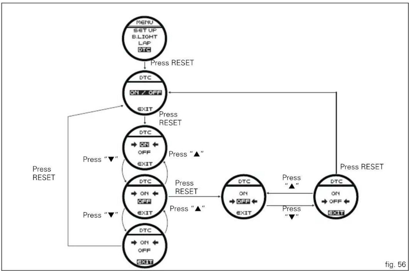
flowchart
graph TD
    A["MENU\nSET UP\nB LIGHT\nLAP\nDTC"] --> B["Press RESET"]
    B --> C["DTC\nON / OFF\nEXIT"]
    C --> D["Press RESET"]
    D --> E["DTC\nON\nOFF\nEXIT"]
    E --> F["Press RESET"]
    F --> G["DTC\nON\nOFF\nEXIT"]
    G --> H["Press RESET"]
    H --> I["DTC\nON\nOFF\nEXIT"]
    I --> J["Press RESET"]
    J --> K["DTC\nON\nOFF\nEXIT"]
    K --> L["Press RESET"]
    L --> M["Press RESET"]
    M --> N["Press RESET"]
    N --> O["DTC\nON\nOFF\nEXIT"]
    O --> P["Press RESET"]
    P --> Q["Press RESET"]
    Q --> R["Press RESET"]
    R --> S["Press RESET"]
    S --> T["Press RESET"]
    T --> U["Press RESET"]
    U --> V["Press RESET"]
    V --> W["Press RESET"]
    W --> X["Press RESET"]
    X --> Y["Press RESET"]
    Y --> Z["Press RESET"]
    Z --> AA["Press RESET"]
    AA --> AB["Press RESET"]
    AB --> AC["Press RESET"]
    AC --> AD["Press RESET"]
    AD --> AE["Press RESET"]
    AE --> AF["Press RESET"]
    AF --> AG["Press RESET"]
    AG --> AH["Press RESET"]
    AH --> AI["Press RESET"]
    AI --> AJ["Press RESET"]
    AJ --> AK["Press RESET"]
    AK --> AL["Press RESET"]
    AL --> AM["Press RESET"]
    AM --> AN["Press RESET"]
    AN --> AO["Press RESET"]
    AO --> AP["Press RESET"]
    AP --> AQ["Press RESET"]
    AQ --> AR["Press RESET"]
    AR --> AS["Press RESET"]
    AS --> AT["Press RESET"]
    AT --> AU["Press RESET"]
    AU --> AV["Press RESET"]
    AV --> AW["Press RESET"]
    AW --> AX["Press RESET"]
    AX --> AY["Press RESET"]


Digital RPM indication function
This function displays the number of RPMs for improved accuracy when setting idle rpm.
To display the function, enter the "setting" menu page 46 and access the "RPM" page.
The display shows the numerical value of the RPM with a precision of 50 rpm.
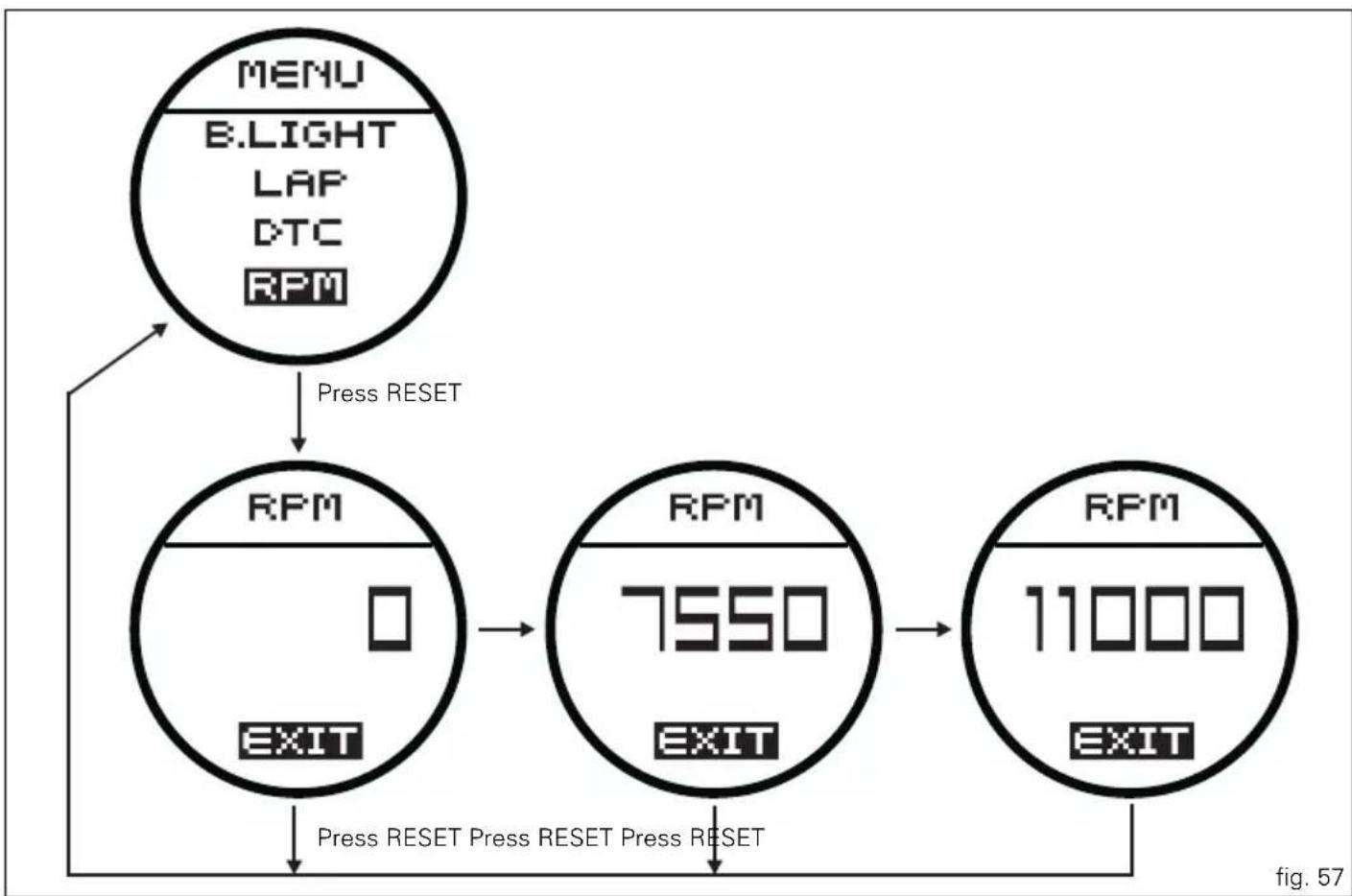
flowchart
graph TD
    A["MENU\nB.LIGHT\nLAP\nDTC\nRPM"] -->|Press RESET| B["RPM\n0\nEXIT"]
    B --> C["RPM\n7550\nEXIT"]
    C --> D["RPM\n11000\nEXIT"]
    D --> E["Exit"]


Clock setting function
This function sets the clock.
To display the function, enter the "setting" menu page 46 and access the "CLOCK" page.
In the next display, press the reset button (14, fig. 4) showing "SET UP" for 3 seconds to proceed with the actual setting.
"SET CLOCK ...." appears on the circular display (B) to indicate that the clock is being set; the time is set on the main display.
Clock setting
On entering this mode, the message "AM" will flash; if you press the button (2, fig. 7) "▼" "PM" flashes;
if you press the button (2, fig. 7) “▼” you will return to the previous step (if it is 00:00, when switching between “AM” to “PM”, 12:00 will be displayed).
pressing button (1, fig. 7) "▲" accesses the hour setting mode; the hours start to flash.
each time you press the button (2, fig. 7) “▼”, the digit will increase by 1 hour; if the button is held pressed down (2, fig. 7) “▼” the digit will increase by 1 hour every second (when the button is held depressed, the hours do not flash).
pressing button (1, fig. 7) "▲" gives access to the minute setting mode; minutes start to flash.
each time you press the button (2, fig. 7) “▼”, the digit will increase by 1 minute; holding down the button (2, fig. 7)
“▼”, the digit will increase by 1 minute each second;
if the button is held depressed (2, fig. 7) “▼” for over 5 seconds, minutes will increase by 1 minute every 100 m (while the button is held depressed (2, fig. 7) “▼”, the seconds will not flash).
pressing button (1, fig. 7) "▲" the indication of the new time will flash and "MEM" will appear on the circular display.
To confirm (store) the new set time press the reset button (14, fig. 4).
To exit, select "EXIT" and press the reset button (14, fig. 4).

Note
If a battery is cutoff, when the voltage is restored and next Key-On, the clock must be reset (it starts natically from 00:00).
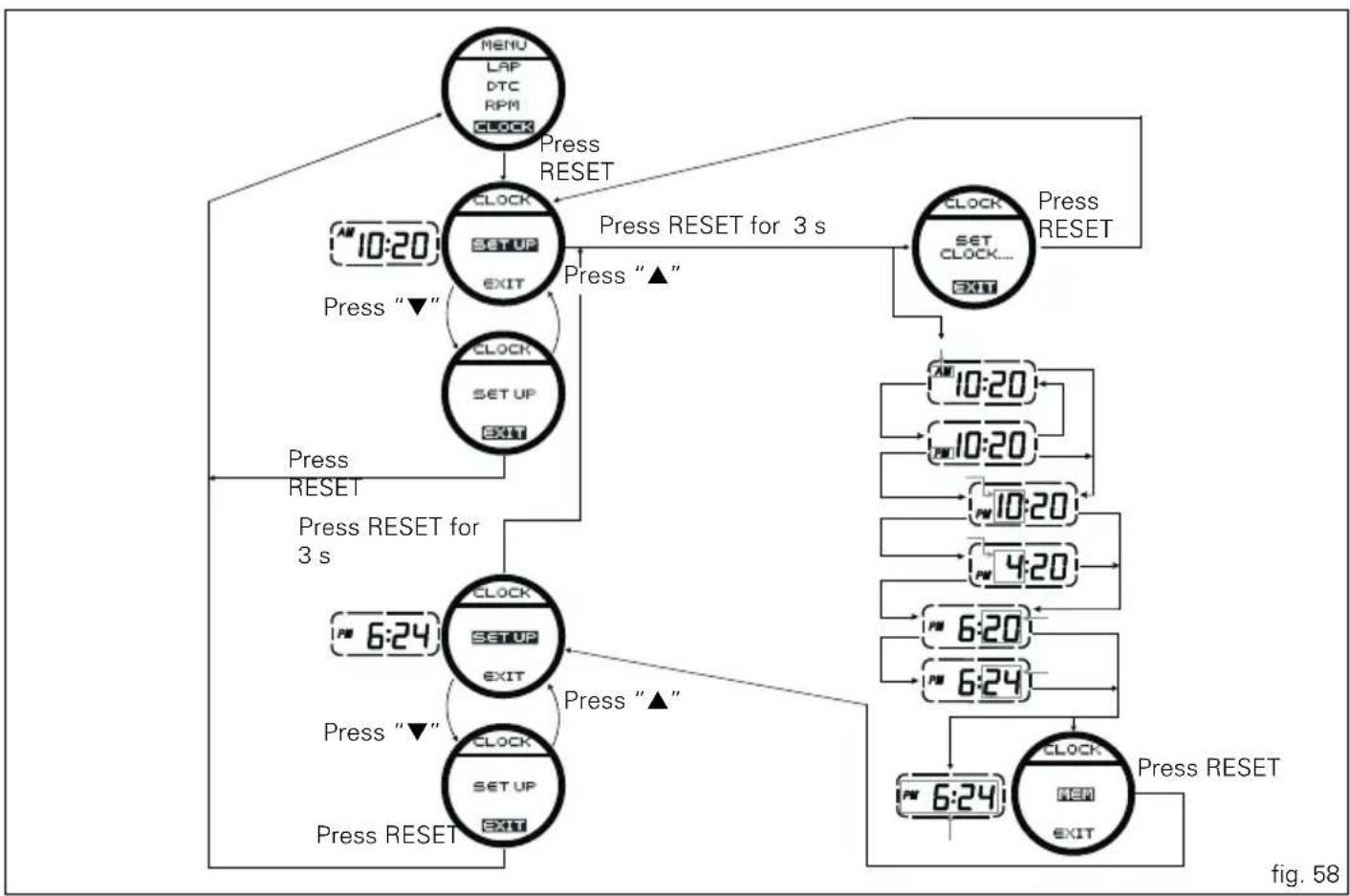
flowchart
graph TD
    A["MENU LAP DTC RPM CLOCK"] -->|Press RESET| B["CLOCK SETUP EXIT"]
    B -->|Press RESET for 3 s| C["CLOCK SETUP EXIT"]
    C -->|Press RESET| D["SET CLOCK... EXIT"]
    D -->|Press RESET| E["10:20"]
    E --> F["10:20"]
    F --> G["10:20"]
    G --> H["4:20"]
    H --> I["6:20"]
    I --> J["6:24"]
    J --> K["6:24"]
    K --> L["6:24"]
    L --> M["6:24"]
    M --> N["6:24"]
    N --> O["6:24"]
    O --> P["6:24"]
    P --> Q["6:24"]
    Q --> R["6:24"]
    R --> S["6:24"]
    S --> T["6:24"]
    T --> U["6:24"]
    U --> V["6:24"]
    V --> W["6:24"]
    W --> X["6:24"]
    X --> Y["6:24"]
    Y --> Z["6:24"]
    Z --> AA["6:24"]
    AA --> AB["6:24"]
    AB --> AC["6:24"]
    AC --> AD["6:24"]
    AD --> AE["6:24"]
    AE --> AF["6:24"]
    AF --> AG["6:24"]
    AG --> AH["6:24"]
    AH --> AI["6:24"]
    AI --> AJ["6:24"]
    AJ --> AK["6:24"]
    AK --> AL["6:24"]
    AL --> AM["6:24"]
    AM --> AN["6:24"]

E
The immobilizer system
For additional antitheft protection, the motorcycle is equipped with an IMMOBILIZER, an electronic system that locks the engine automatically whenever the ignition switch is turned off.
The grip of each ignition key contains an electronic device that modulates the output signal from a special antenna in the top fairing when the ignition is switched On. The modulated signal acts as a password (which is different at each start-up) and tells the ECU that an "authorised" ignition key is being used to start up the engine. When the ECU recognises the signal, it enables engine start-up.
Keys (fig. 59)
The Owner receives a set of keys comprising:
- 1 active key (1, fig. 59)
- 1 passive key (2, fig. 59)
It contains the code used by the "Hands free" system for the Key-On, in different modes.
The active key (1, fig. 60) is the one that is normally used and has a button (A, fig. 60) that when pressed makes the metal part exit (B, fig. 60). The metal part returns inside the grip by pushing it in.
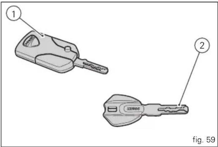
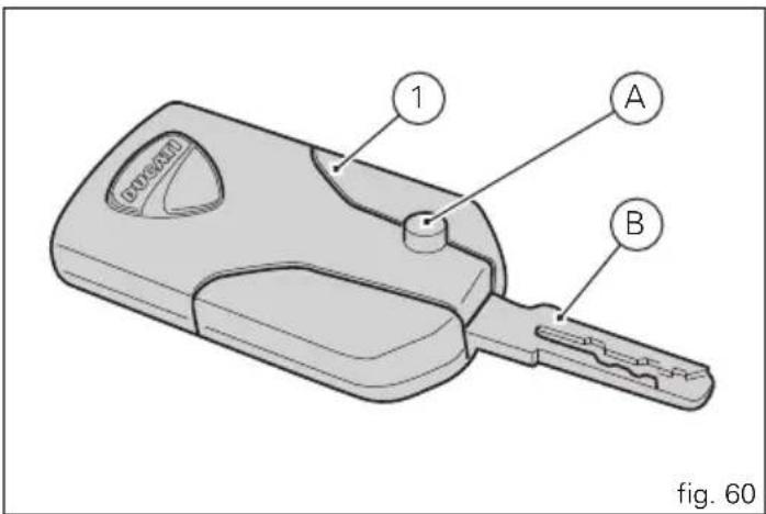
The key contains a battery that must be replaced when the message "low level" is displayed under the key and battery symbols when the instrument panel is turned on (fig. 61).

Note
In this case, replace the battery as soon as possible (page 86).
When the charge level goes below a certain limit, the key can only work in passive mode, like the passive key: in this case, the instrument panel will not display any message.

Warning
Do not ride with the key (1 or 2, fig. 59) inserted in the lock of the tank cap or in the seat lock as it could come out and represent a potential danger. Furthermore, if bumped, the key mechanism and the integrated circuit could be damaged.
Also riding in poor weather conditions with the key inserted could cause damage to its integrated circuit.
Do not leave the key on the motorcycle when washing it as it could be damaged, not being watertight.
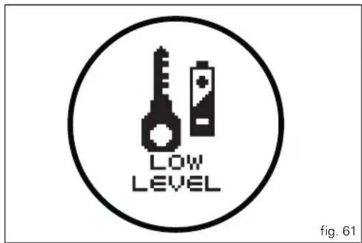


Replacing the battery in the active key Only use 3 Volt CR 2032 lithium ion batteries.

Note
The keys do not need to be reprogrammed after using the battery.
Remove the metal part of the battery. Use a large sized coin to pry open the shells of the plastic grip (2€ coin) as shown in fig. 62.

Important
Insert the coil only in the indicated point. Do not other use other objects inserted in points that are different than what is shown, as it could damage the integrated circuit and/or the protective gasket.
Once the plastic shells have been separated, remove the printed circuit board (1, fig. 63) prying it up GENTLY with a small flat screwdriver, as shown in the figure.

Important
Insert the point of the flat screwdriver just under the printed circuit board, being very careful not to damage it. Do not apply force on the battery or battery holder.
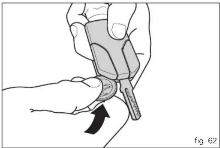
natural_image
Illustration of a hand holding a small object with an arrow indicating rotation (no text or symbols)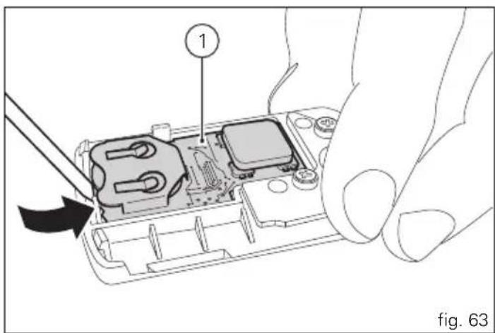
Remove the battery (2, fig. 64) from the printed circuit board (1, fig. 64) and replace it with a new one.
Pay attention to polarity: the positive pole (+) must face upward.

Important
Only use the required type of battery.
Reinsert the printed circuit board (1, fig. 65) from the side with the battery (2, fig. 65) into the plastic shell.
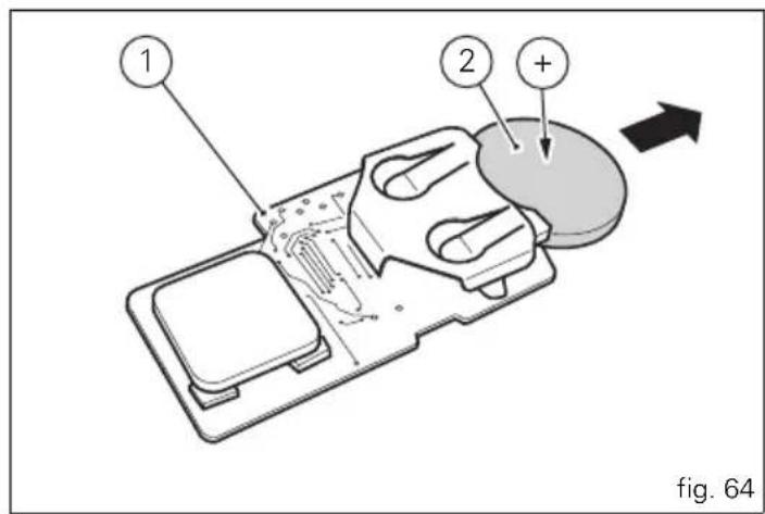

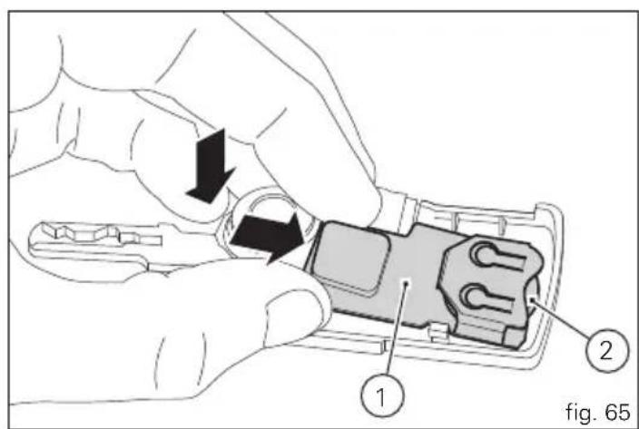

Apply slight pressure on the antenna (3, fig. 66) of the printed circuit board until you hear a click.
Align the two shells of the grip and press on the area indicated by the arrows (fig. 67) to reclose them.
Make sure that you hear a "click" upon closing and that the key is well closed.
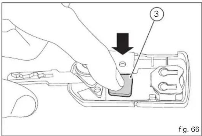
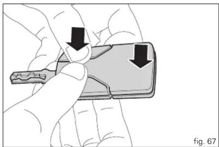
natural_image
Illustration of a hand holding a small object with two downward arrows indicating movement or force (no text or symbols present)Duplicate keys
If you need any duplicate keys, contact the Ducati Service network with all the keys you have left.
The Ducati Service Centre will program all the new keys as well as any keys you already have.
You may be asked to provide proof that you are the legitimate owner of the motorcycle.
The codes of any keys not submitted will be wiped off from the memory to make those keys unserviceable in case they have been lost.


Immobilizer override procedure
This procedure makes it possible to "temporarily" turn on the motorcycle if the HF (Hands Free) System is not working.

Note
The PIN CODE function must be activated by entering your 4 digit PIN in the instrument panel, otherwise the vehicle cannot be turned on temporarily in the case of a malfunction.

Warning
The motorcycle owner must activate (store) the PIN code; if there is already a stored PIN, contact an Authorised Ducati dealer to have the function "reset". To perform this procedure, the Authorised Ducati Dealer may ask you to demonstrate that you are the owner of the motorcycle.
PIN CODE activation function
To display the function, enter the "setting" menu page 46 and access the "PIN CODE" page.

Note
If "MODIFY" appears when accessing this function, this means that there is already a stored PIN and therefore the function is already active.
When accessing the function, "NEW PIN" four dashes "----" will appear on the circular display (B, fig. 6); now enter a 4 digit code.
Entering the code:
each time you press the button (2, fig. 7) "▼" the displayed number increases from "0" to "9" and then returns to "0"; to confirm the number, press the reset button (14, fig. 4).
Repeat the procedure until inserting the fourth digit.
Press the reset button (14, fig. 4) again to confirm.
"OK" and "EXIT" will appear on the display.
To confirm the PIN that was entered, press the reset button (14, fig. 4) again showing "OK".
"NEW PIN MEM" will appear on the display for 3 seconds to confirm that the PIN was stored.
At the end of the 3 seconds, the instrument panel exits automatically from the display and returns to the "setting" menu.
From this moment, "MODIFY" will be displayed when accessing the "PIN CODE" function and the PIN can be changed again.
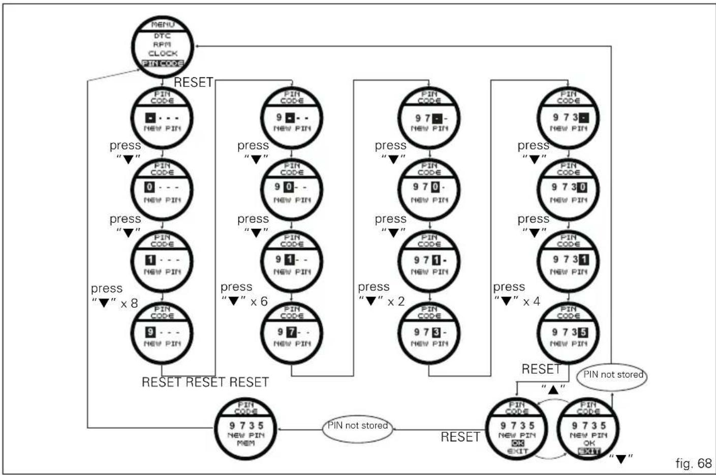
flowchart
graph TD
    A["MENU DTC RPM CLOCK PIN CODE"] --> B["RESET"]
    B --> C["FIN CODE: NEW PIN"]
    C --> D["pres: "▼""]
    D --> E["FIN CODE: 0 - NEW PIN"]
    E --> F["pres: "▼""]
    F --> G["FIN CODE: 1 - NEW PIN"]
    G --> H["pres: "▼" x 8"]
    H --> I["FIN CODE: 9 - NEW PIN"]
    I --> J["RESET RESET RESET"]
    J --> K["PIN CODE: 9735 NEW PIN MEM"]
    K --> L["PIN not stored"]
    L --> M["RESET"]
    M --> N["PIN CODE: 9735 NEW PIN OK EXIT"]
    N --> O["PIN not stored"]
    O --> P["PIN CODE: 9735 NEW PIN OK EXIT"]
    P --> Q["RESET"]
    Q --> R["PIN not stored"]
    R --> S["FIN CODE: 9735 NEW PIN NOT EXITS"]
    S --> T["PIN not stored"]
    T --> U["PIN CODE: 9735 NEW PIN NOT EXITS"]
    U --> V["PIN not stored"]


PIN CODE change function
This function changes your four number PIN CODE. To display the function, enter the "setting" menu page 46 and access the "PIN CODE" page.
If the code is not correct, "OLD PIN WRONG" will appear for 3 seconds and then the instrument panel will return displaying "MODIFY" so you can repeat the attempt of entering the "old" code.

Note
If "NEW PIN" and the dashes "----" appear when
accessing this function, this means that the function was not active as the PIN CODE was never entered. Enter your PIN as described in the previous paragraph "PIN CODE activation function".
When accessing the function, "MODIFY" will appear on the circular display (B, fig. 6); press the reset button (14, fig. 4) showing "MODIFY" to modify the PIN.

Note
To change the PIN, you must know the currently stored
PIN.
"OLD PIN" and four dashes "----" will appear on the circular display (B, fig. 6); enter the old 4 digit code that was stored previously.
Entering the "old" PIN: each time you press the button (2, fig. 7) "▼" the displayed number increases from "0" to "9" and then returns to "0".
To confirm the number, press the reset button (14, fig. 4); repeat the procedure until inserting the fourth digit;
Press the reset button (14, fig. 4) again to confirm.
"OK" and "EXIT" will appear on the display.
To confirm the "old" PIN that was entered, press the reset button (14, fig. 4) again showing "OK".
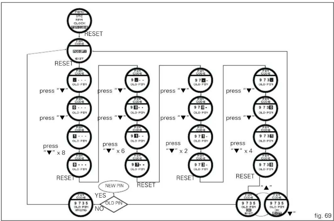
flowchart
graph TD
    A["RESET"] --> B["FIN CODE"]
    B --> C["RESET"]
    C --> D["FIN CODE"]
    D --> E["pres "▼""]
    E --> F["FIN CODE"]
    F --> G["pres "▼""]
    G --> H["FIN CODE"]
    H --> I["pres "▼" x 8"]
    I --> J["FIN CODE"]
    J --> K["RESET"]
    K --> L["FIN CODE"]
    L --> M["YES"]
    M --> N{OLD PIN}
    N --> O["NO"]
    O --> P["FIN CODE"]
    P --> Q["9 7 35 OLD PIN WRONG"]
    Q --> R["NEW PIN"]
    R --> S["FIN CODE"]
    S --> T["pres "▼""]
    T --> U["FIN CODE"]
    U --> V["pres "▼""]
    V --> W["FIN CODE"]
    W --> X["pres "▼" x 2"]
    X --> Y["FIN CODE"]
    Y --> Z["RESET"]
    Z --> AA["FIN CODE"]
    AA --> AB["pres "▼""]
    AB --> AC["FIN CODE"]
    AC --> AD["pres "▼" x 4"]
    AD --> AE["FIN CODE"]
    AE --> AF["RET"]
    AF --> AG["FIN CODE"]
    AG --> AH["9 7 35 OLD PIN OK EXIT"]
    AH --> AI["RET"]


If the code was entered correctly the message "NEW PIN" and four dashes "----" will appear on the circular display; now enter the "new" 4 digit code.
Entering the "new" PIN: each time you press the button (2, fig. 7) "▼" the displayed number increases from "0" to "9" and then returns to "0";
to confirm the number, press the reset button (14, fig. 4).
repeat the procedure until inserting the fourth digit;
Press the reset button (14, fig. 4) again to confirm.
"OK" and "EXIT" will appear on the display.
To confirm the PIN that was entered, press the reset button (14, fig. 4) again showing "OK".
"NEW PIN MEM" will appear on the display for 3 seconds to confirm that the PIN was stored.
At the end of the 3 seconds, the instrument panel exits automatically from the display and returns to the "setting" menu.
The PIN CODE modification procedure is complete.

Note
There is no limit to the amount of times you can
change your PIN CODE.
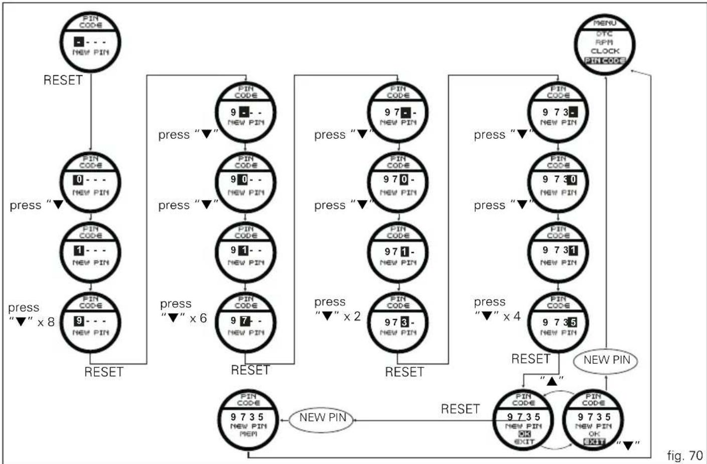
flowchart
graph TD
    A["RESET"] --> B["PIN CODE 0 - - NEW PIN"]
    B --> C["press "▼""]
    C --> D["PIN CODE 1 - - NEW PIN"]
    D --> E["press "▼" x 8"]
    E --> F["RESET"]
    F --> G["PIN CODE 9 - - NEW PIN"]
    G --> H["press "▼" x 6"]
    H --> I["PIN CODE 97 - NEW PIN"]
    I --> J["RESET"]
    J --> K["PIN CODE 9735 NEW PIN MEM"]
    K --> L["NEW PIN"]
    L --> M["RESET"]
    M --> N["PIN CODE 9735 NEW PIN OK EXIT"]
    N --> O["NEW PIN"]
    O --> P["PIN CODE 9735 NEW PIN OK EXIT"]
    P --> Q["NEW PIN"]
    Q --> R["PIN CODE 9735 NEW PIN OK EXIT"]
    R --> S["NEW PIN"]
    S --> T["PIN CODE 9735 NEW PIN OK EXIT"]
    T --> U["NEW PIN"]
    U --> V["PIN CODE 9735 NEW PIN OK EXIT"]
    V --> W["NEW PIN"]
    W --> X["PIN CODE 9735 NEW PIN OK EXIT"]
    X --> Y["NEW PIN"]
    Y --> Z["PIN CODE 9735 NEW PIN OK EXIT"]
    Z --> AA["NEW PIN"]
    AA --> AB["PIN CODE 9735 NEW PIN OK EXIT"]
    AB --> AC["NEW PIN"]
    AC --> AD["PIN CODE 9735 NEW PIN OK EXIT"]
    AD --> AE["NEW PIN"]
    AE --> AF["PIN CODE 9735 NEW PIN OK EXIT"]
    AF --> AG["NEW PIN"]
    AG --> AH["PIN CODE 9735 NEW PIN OK EXIT"]
    AH --> AI["NEW PIN"]
    AI --> AJ["PIN CODE 9735 NEW PIN OK EXIT"]
    AJ --> AK["NEW PIN"]
    AK --> AL["PIN CODE 9735 NEW PIN OK EXIT"]
    AL --> AM["NEW PIN"]
    AM --> AN["PIN CODE 9735 NEW PIN OK EXIT"]
    AN --> AO["NEW PIN"]
    AO --> AP["PIN CODE 9735 NEW PIN OK EXIT"]
    AP --> AQ["NEW PIN"]
    AQ --> AR["PIN CODE 9735 NEW PIN OK EXIT"]
    AR --> AS["NEW PIN"]
    AS --> AT["PIN CODE 9735 NEW PIN OK EXIT"]
    AT --> AU["NEW PIN"]
    AU --> AV["PIN CODE 9735 NEW PIN OK EXIT"]
    AV --> AW["NEW PIN"]


Light control
Headlight control
This function allows you to reduce current consumption from the battery, by automatically managing headlight switching-off.
At Key-On, the high beam and low beam lights are off. When the engine is started, the low beam lights turn on automatically; from this moment, "normal" operation is activated: it is possible to switch between low beams and high beams (with button 13, fig. 4) or "FLASH" the lights (with button 13, fig. 4). If the engine is not started at Key-On, the lights can be turned on by pressing the button on the left high beam / low beam light switch (button 13, fig. 4); the low beam lights are turned on the first time it is pressed; from this moment, the same button can be used to switch between the low beam and high beam lights (if the engine is not started within 60 seconds, the low beam or high beam light that were turned on will turn off).
If the headlight was turned on before starting the engine with the procedure described above, the headlight turns off automatically when starting the vehicle and will turn on again when the engine has been completely started.
Turn signals (automatic reset)
The instrument panel controls the automatic reset of the turn signals.
After activating one of the two turn signals, they can be deactivated using the RESET button (14, fig. 4). If the turn signal is not "reset" manually, the instrument panel will automatically switch it off after the motorcycle has travelled 500 m (0.3 miles) from when the turn signal was activated.
The counter for the distance travelled for automatic deactivation is activated at speeds below 80 Km/h (50 mph). If the calculation of the distance for automatic deactivation is activated and then the motorcycle exceeds a speed of 80 km/h (50 mph), the calculation is interrupted and will restart when the speed returns below the indicated threshold.
"Parking" function
This function activates the "PARKING" mode.
The "PARKING" function activates the front and rear parking lights when the vehicle is turned off so it is visible when parked.
The function is activated by pressing the button (2, fig. 7) “▼” for 3 seconds during the first 60 seconds after the motorcycle was turned off.
Once the function is activated, the indication will remain on the circular display for 5 seconds and the lights will remain on for 2 hours. After 2 hours, then will turn off automatically.
To interrupt the function, turn the vehicle on and off.

Note
If there is a sudden interruption in the battery while the
function is active, the instrument panel will disable the function when the voltage is restored.

Warning
The frequent use of this function can considerably
reduce the battery charge; Ducati recommends using this function only when necessary.
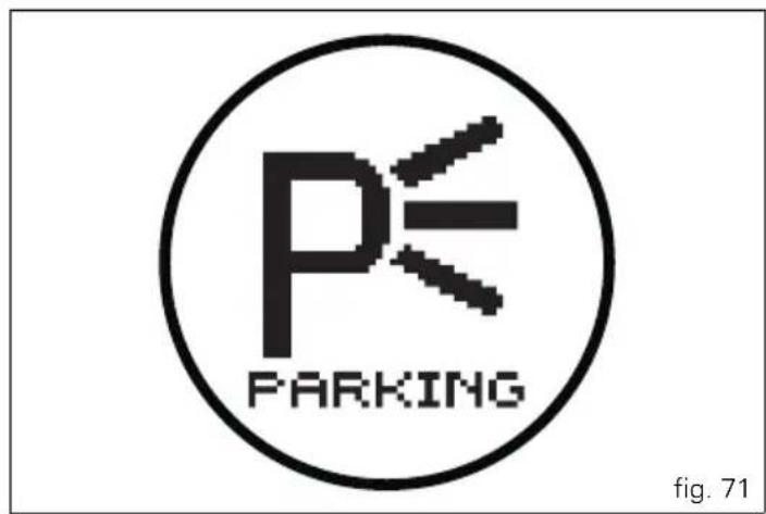


"Steering in position for being locked" indication
This function informs that the steering is in position for turning on the steering lock.
The sensors detect that the steering is in position during the first 60 seconds after turning off the vehicle and the instrument panel activates the indication on the circular display for max. 5 seconds.
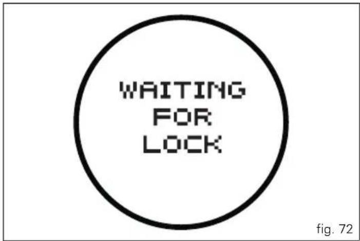
"Steering lock" on indication
This function informs that the steering lock was turned on. The steering lock can be turned on during the first 60 seconds after turning off the vehicle by pressing down on the "RUN" button.
If the steering lock was turned on correctly, the instrument panel will show the indication in the circular display for 5 seconds.

Note
The steering lock can only be turned on when the ng is in position.
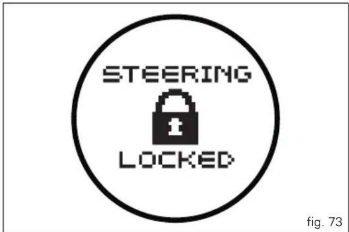
Controls

Warning
This section shows the position and function of the controls used to drive the motorcycle. Be sure to read this information carefully before you use the controls.
Position of motorcycle controls (fig. 74)
1) Instrument panel.
2) "Hands free" system.
3) Left-hand handlebar switch.
4) Clutch lever.
5) Rear brake pedal
6) Right-hand handlebar switch.
7) Throttle twistgrip.
8) Front brake lever.
9) Gear change pedal.
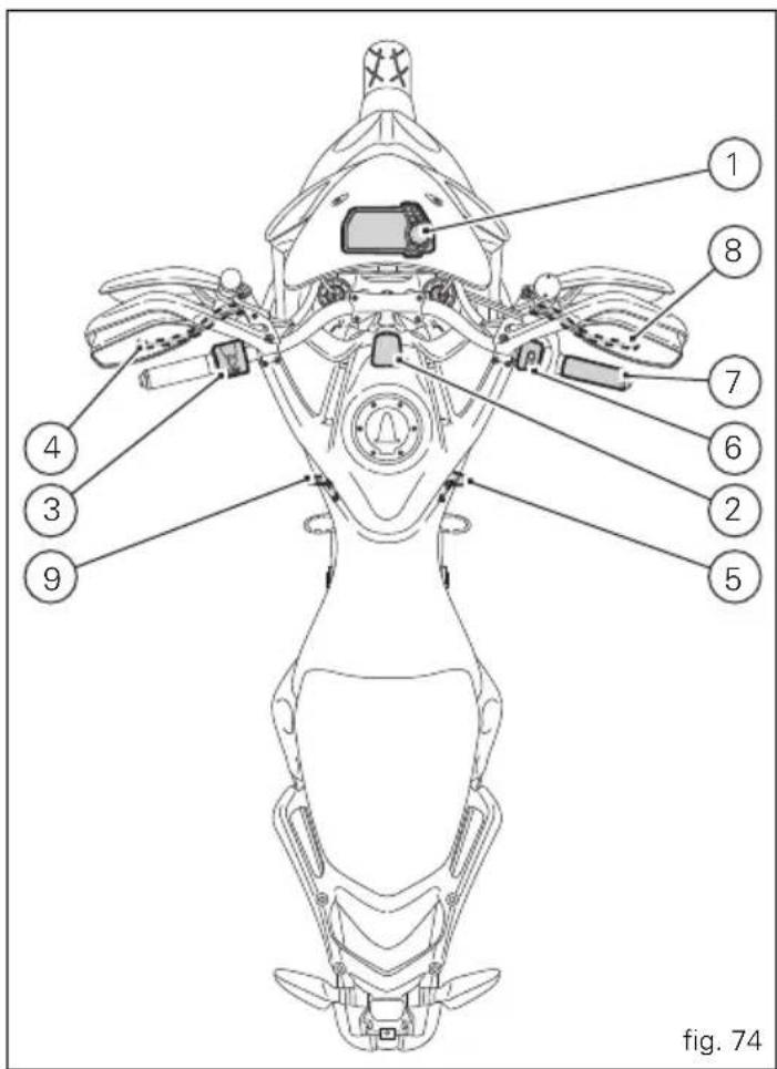


"Hands free" system
The Hands free system consists of:
1) Hands free lock;
2) Antenna;
3) Active key;
4) Passive key;
5) Electric cap (optional).
The "Hands free" lock (1, fig. 75) is located on the front of the tank. The door must be removed to access it (2).

Note
In the USA version the door (2, fig. 77) is not present
(fig. 77).
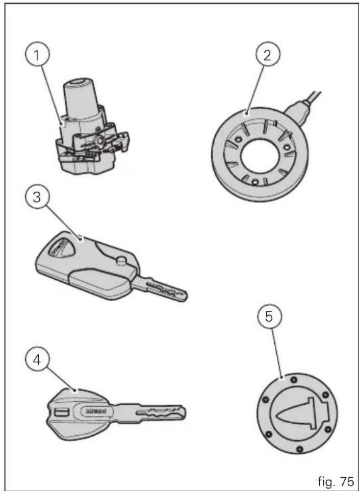
Hands free system Key-On and Key-Off
Key-On consists in turning on the hands free system and all of its electronic devices.
Key-Off consists in turning off the hands free system and all electronic devices, and makes sure the engine is turned off. Key-On is done using the button (6) on the handlebar on the right switch or using the emergency button (7) on the Hands free lock (1, fig. 75).
Key-Off is done using the button (6, fig. 76) on the handlebar on the right switch or using the emergency button (7) on the Hands free lock (1, fig. 76).

Warning
The button (7) is hidden under the door (8). Remove it to access the button (7). In the USA version the door (8) is not present.

Note
The use of one of the two buttons (6) or (7) does not exclude the other, ex.: if I turn it on with one, I can turn it off with the other and vice versa.
Key-On can only occur in the presence of one of the two keys (3, fig. 75) or (4, fig. 75) or using the pin code.
Key-Off can also occur without a key (3, fig. 75) or (4, fig. 75). Key-Off occurs when the speed of the motorcycle is equal to zero, pressing the button (6) on the handlebar or by pressing the Hands free button (7); at a speed other than zero, only by pressing the Hands free button (7).
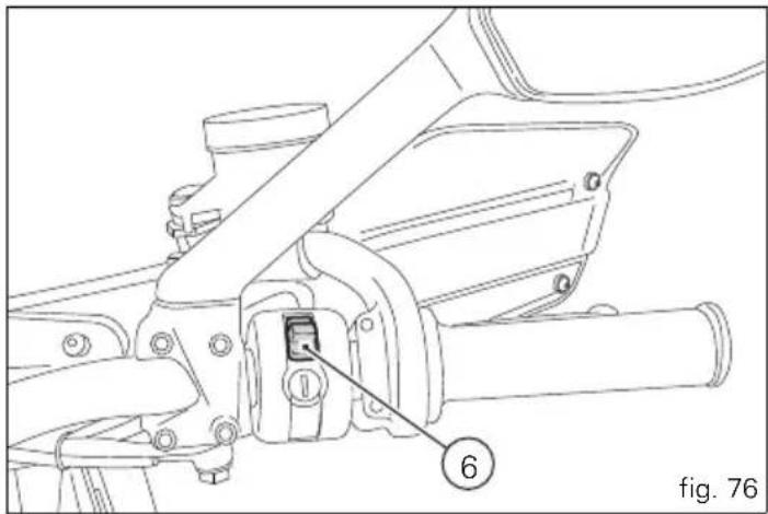

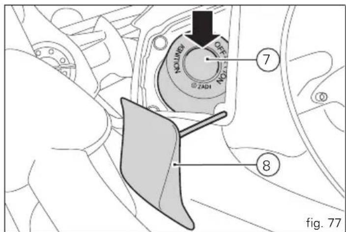


Note
When the battery is discharged, the active key (3, fig. 75) acts like a passive key (4, fig. 75). The instrument panel displays the discharged battery status.
The mechanical part (A) of the key (3) is used to open the fuel cap and the seat and bag lock.
The metal part (A) of the key (3) remains hidden inside its housing, it exits by pressing the button (B, fig. 79).

Note
With the vehicle in Key-On and "engine off", if the presence of the active key (3, fig. 79) is not detected for thirty consecutive seconds, the motorcycle will turn off automatically without any action by the rider.
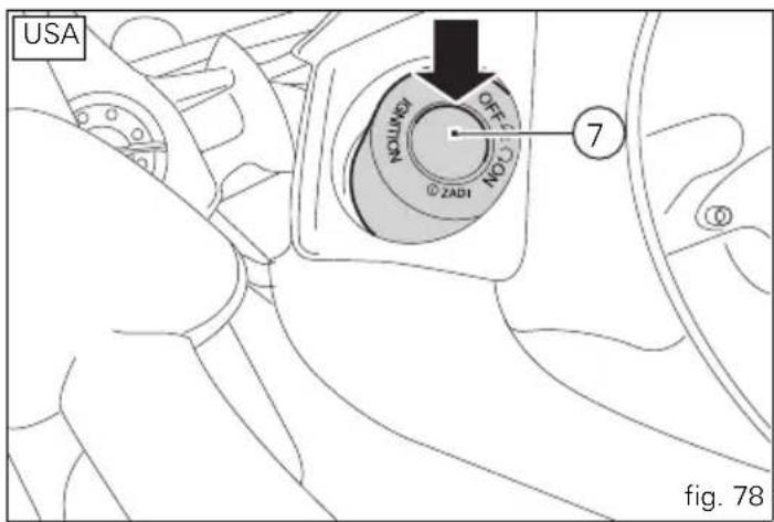
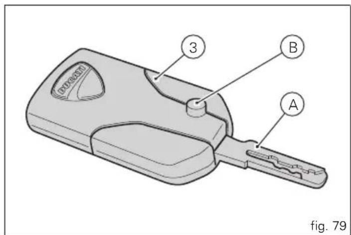
Key-On/Key-Off using the red key on the handlebar with the active key
A Key-On can be performed by pressing the red key (6) on the handlebar in the HANDS FREE ON/OFF position and in the presence of the active key (3, fig. 75).

Note
The active key (3, fig. 75) has a range of approx. 1.5 m, therefore it must be located within this range.
Key-Off can be performed by pressing the red key (6) on the handlebar in the HANDS FREE ON/OFF position. It can be done also without the key (3, fig. 75) only if the motorcycle speed is equal to zero.
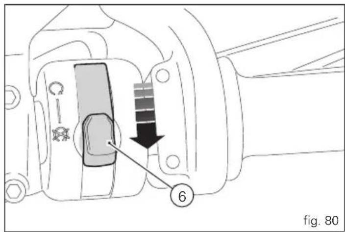

Key-On/Key-Off using the key on the Hands free lock with the active key
Key-On can be performed by pressing the button (7) on the Hands free lock (1, fig. 75) and with the presence of the active key (3, fig. 75).

Note
In the USA version the door (8) is not present.

Note
The active key (3, fig. 75) has a range of approx. 1.5 m,
therefore it must be located within this range.
Key-Off can be performed by pressing the button (7) on the Hands free lock (1, fig. 75), also without the key (3, fig. 75).
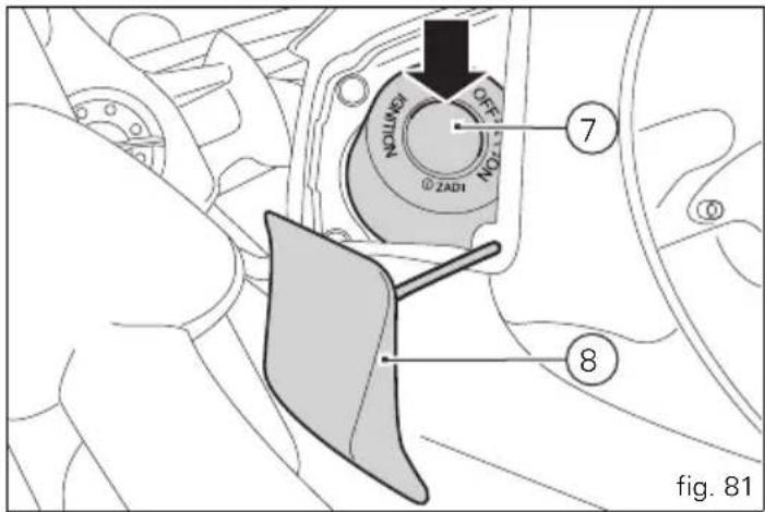
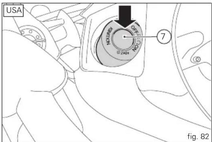
Key-On/Key-Off using the red key on the handlebar with the passive key
A Key-On can be performed by pressing the red button (6) on the handlebar in the HANDS FREE ON/OFF position and in the presence of the passive key (4, fig. 75).

Note
The passive key (4, fig. 75) has a range of a few cm, therefore the key (4, fig. 75) must be positioned near the antenna (2).
Key-Off can be performed by pressing the red button (6) on the handlebar in the HANDS FREE ON/OFF position. It can be done also without the key (4, fig. 75) only if the motorcycle speed is equal to zero.
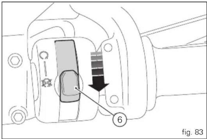

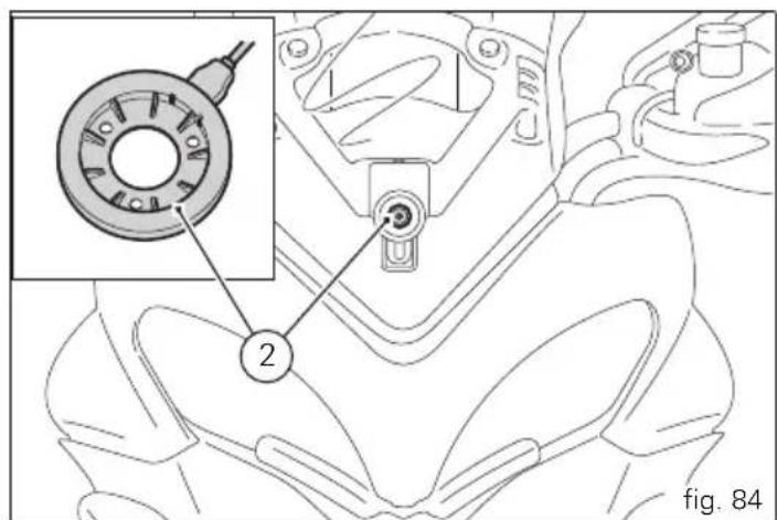

Key-On/Key-Off using the key on the Hands free lock with the passive key
Key-On can be performed by pressing the button (7) on the Hands free lock and with the presence of the passive key (4, fig. 75).

Note
In the USA version the door (8) is not present.

Note
The passive key (4, fig. 75) has a range of a few cm,
therefore the key (4, fig. 75) must be positioned near the antenna.
Key-Off can be performed by pressing the button (7) on the Hands free lock (1, fig. 75), also without the key (4, fig. 75).
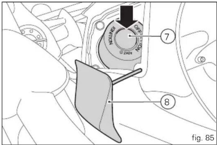
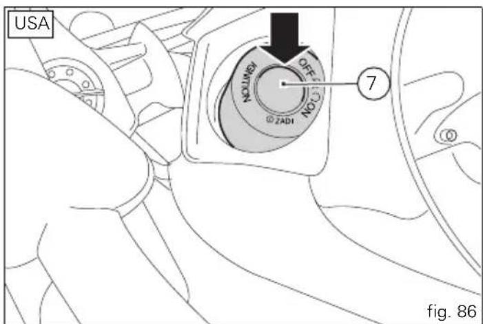
Key-On/Key-Off using the pin code (immobilizer release)

Note
In the USA version the door (8) is not present.
Key-On can be performed by pressing the button (7) on the hands free lock (1, fig. 75) without the presence of the keys (3, fig. 75) and (4, fig. 75) and entering the pin code on the dashboard.
Key-Off can be performed by pressing the button (6) on the handlebar / Hands Free key (7) / engine off no key.
After each Key-Off, at the next Key-On if the key is not present the pin code must be entered.
The pin code is entered by the customer when receiving the motorcycle.
The function is not enabled without the pin code.
When the Hands Free button is pressed (7) the instrument panel activates the backlighting and the circular display to be able to enter the four digit pin code. Entering the correct pin turns on the instrument panel and enables engine starting.
The pin must be entered within 120 sec, after which a Key-Off occurs automatically.
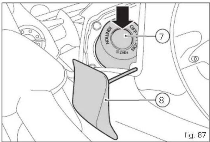

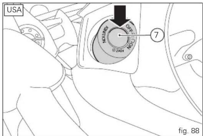

Entering PIN CODE function for vehicle release
This function turns on the motorcycle “temporarily” in the case of HF (Hands Free) system “malfunctions”.
To activate the function, press the "emergency" Hands Free button (7, fig. 87) lifting the door (8, fig. 87) if the motorcycle cannot be turned on using the normal starter button.

Note
In the USA version the door (8, fig. 87) is not present.
After pressing the button, the instrument panel activates only the circular display (B, fig. 6) (and the backlighting) to be able to enter the 4 digit PIN code.
Entering the code:
each time you press the button (2, fig. 7) "▼" the displayed number increases from "0" to "9" and then returns to "0"; to confirm the number, press the reset button (14, fig. 4); repeat the procedure until inserting the fourth digit; press the reset button (14, fig. 4) again to confirm.
If the code is incorrect, the instrument panel will return to the initial indication in order to enter the code again.

Note
There is no limit to the number of times the code can be re-entered; the instrument panel will turn off automatically 120 seconds after an attempt to enter the code.
If the code was entered correctly, the message "PIN OK" will flash on the display for 4 seconds. After 4 seconds, the instrument panel will return to the "normal" view (with all indications active).
From this moment, the vehicle can be started using the start button (Key-On).

Note
The vehicle can be started until a Key-Off is performed; if the problem still persists upon the next starting attempt, repeat the procedure from the beginning in order to start the motorcycle "temporarily".

Important
If this procedure is necessary in order to start the vehicle, contact an Authorised Ducati Service Centre as soon as possible to fix the problem.
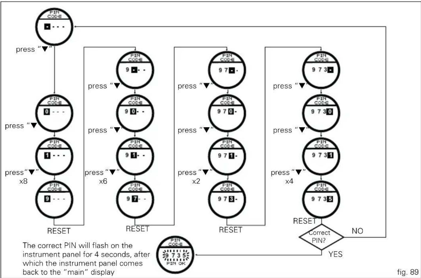
flowchart
Instrument panel control flowchart with PIN code inputs, press buttons, and confirmation logic for flash display
E
LH switch (fig. 74)
1) Dip switch, light dip switch, two positions (fig. 90):
(A) pushed up low beam on;
(B) pushed down high beam on;
(C) pushed to the side ☑ high beam flasher (FLASH), "Start-Stop lap" function.
2) Button three-position turn signal (fig. 91): centre position = OFF;
position ← left turn;
position right turn.
3) Turn signal off, "Riding Style" activation and menu navigation button.
4) Button warning horn.
5) Navigation menu, main display scroll and TRIP1 and TRIP2 reset button.
6) Navigation menu, circular Dot-Matrix display scroll button.
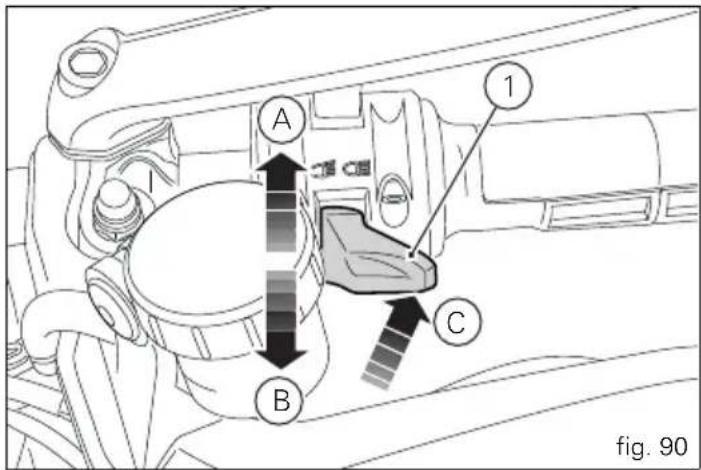
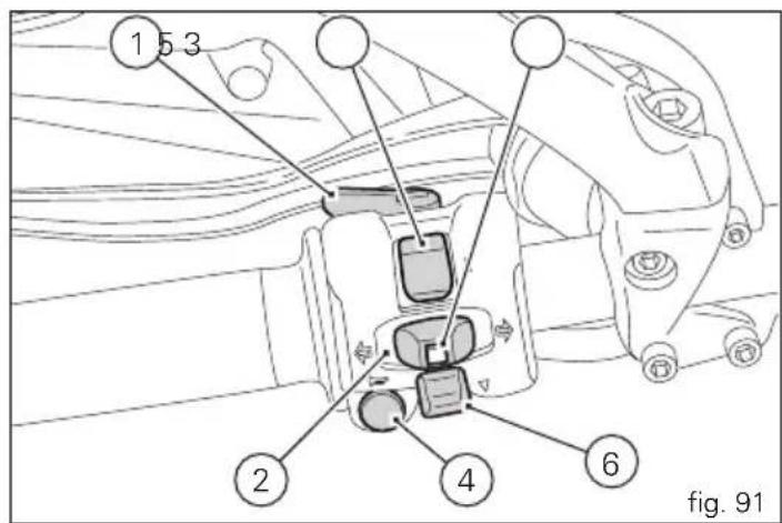
Clutch lever (fig. 92)
Lever (1) disengages the clutch. It features a dial adjuster (2) for lever distance from the twistgrip on handlebar.
The lever distance can be adjusted through 10 clicks of the dial (2). Turn clockwise to increase lever distance from the twistgrip. Turn the adjuster counter clockwise to decrease lever distance.
When the clutch lever (1) is operated, drive from the engine to the gearbox and the drive wheel is disengaged. Correct use of the clutch lever is very important in all riding situations, especially when moving off.

Warning
Any adjustment of clutch lever must be carried out
when motorcycle is stationary.

Important
Using the clutch properly will avoid damage to
transmission parts and spare the engine.

Note
It is possible to start the engine with the side stand
down and the gearbox in neutral. When starting the bike with a gear engaged, pull the clutch lever (in this case the side stand must be up).
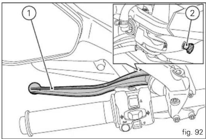

RH switch (fig. 93)
1) Red ON/OFF switch.
2) Black ENGINE START button
The switch (1, fig. 93) has three positions:
A) centre: RUN OFF. In this position, the engine cannot be started and all electronic devices are off.
B) pushed down: ON/OFF. In this position, the system can be turned on (Key-On) and off (Key-Off).
C) pushed up: RUN ON. The engine can only be started in this position, pushing the black button (2).
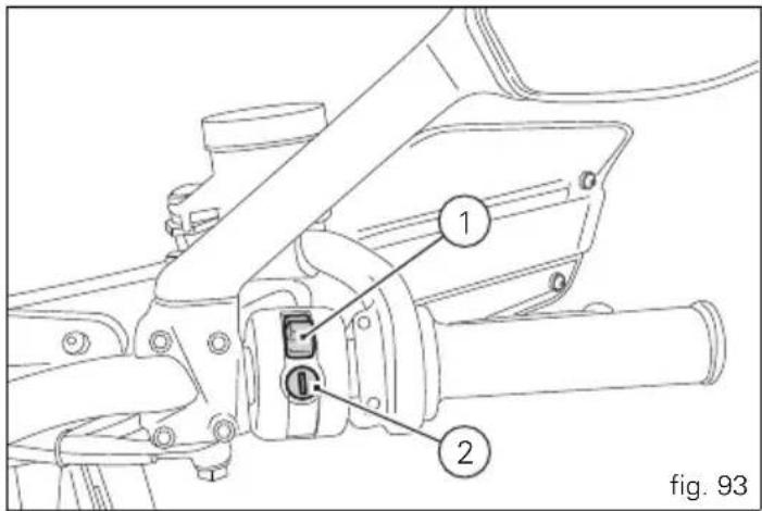
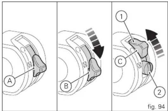
Throttle twistgrip (fig. 95)
The twistgrip on the right handlebar opens the throttles. When released, it will spring back to the initial position (idling speed).
Front brake lever (fig. 96)
Pull in the lever (1) towards the twistgrip to operate the front brake. The system is hydraulically assisted and you only need to pull the lever gently.
The brake lever (1) has a dial (2) for adjusting the distance between lever and twistgrip on the handlebar.
The lever distance can be adjusted through 10 clicks of the dial (2). Turn clockwise to increase lever distance from the twistgrip. Turn the adjuster counter clockwise to decrease lever distance.
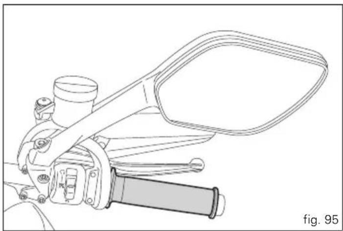
natural_image
Technical line drawing of a mechanical lever assembly (no text or symbols)
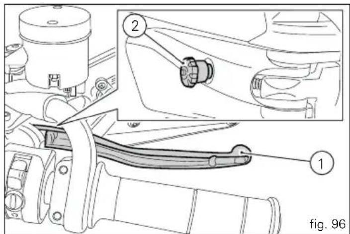

Rear brake pedal (fig. 97)
Push down on the pedal with your foot to operate the rear brake.
The system is hydraulically controlled.
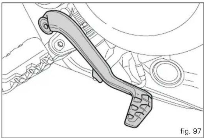
natural_image
Technical line drawing of a mechanical lever assembly (no text or symbols)Gear change pedal (fig. 98)
The gear change pedal is at rest when in centre position N with automatic spring-back. This is indicated by the instrument panel light N (3, fig. 3) coming on.
The pedal can be moved:
down = press down the pedal to engage the 1 ^st gear and to shift down. At this point the N light on the instrument panel will go off;
upwards= lift the pedal to engage 2^nd gear and then 3^rd , 4^th , 5^th and 6^th gears.
Each time you move the pedal you will engage the next gear.
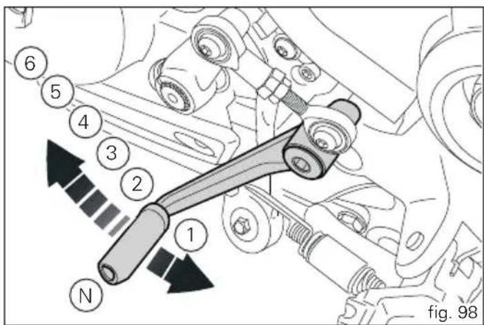
Adjusting the position of the gearchange and rear brake pedals
The position of the gearchange and rear brake pedals in relation to the footrests can be adjusted to suit the requirements of the rider.
Adjust the pedals as follows:
Gear change pedal (fig. 99)
Use an open ended spanner to hold the spherical end on the rod (1) on the flat (2) and loosen the counter nut (3).
Turn the screw (4) to detach the rod completely from the gear change lever.
Turn the rod (5), until the gear change pedal is set to the desired position.
Tighten the screw (4) to secure the gearchange lever to the rod (5).
Tighten the counter nut (3) onto the spherical end (5).
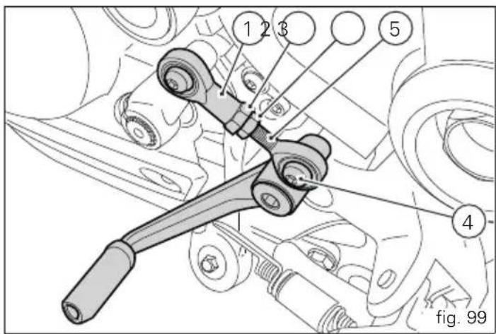

Rear brake pedal (fig. 100)
loosen counter nut (7).
Turn pedal travel adjusting screw (6) until pedal is in the desired position.
Tighten the counter nut (7).
Operate the pedal by hand to check that there is 1.5 to 2 mm of freeplay before the brake bites.
If not, adjust the length of the master cylinder pushrod as follows.
Slacken off the counter nut (10) on the pushrod.
Screw the pushrod (8) into the clevis (9) to increase the freeplay, or screw it out to reduce it.
Tighten the counter nut (10) and recheck the pedal freeplay.
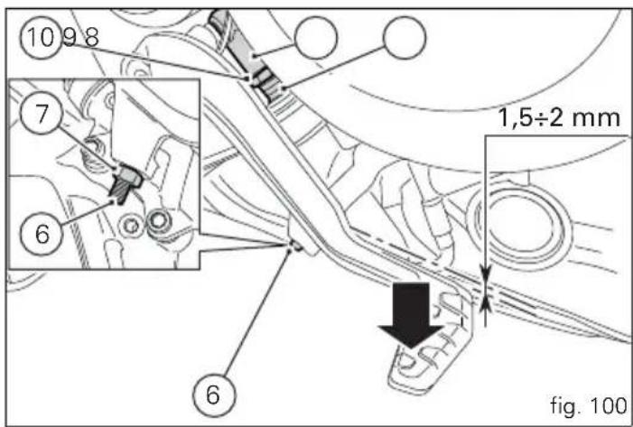
Main components and devices
Position on the vehicle (fig. 101)
1) Tank filler plug.
2) Seat lock.
3) Side stand.
4) Power outlet
5) Rear-view mirrors.
6) Front fork adjusters.
7) Rear shock absorber adjusters.
8) Catalytic converter.
9) Exhaust silencer (see "Warning" on page 137).
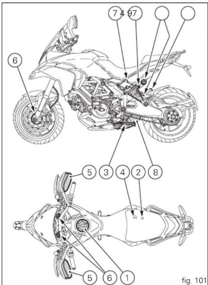

Tank filler plug
Opening
Lift the cover (1, fig. 102) and insert the active or passive key into the lock. Give the key a 1/4 turn clockwise to unlock. Lift the plug (2, fig. 103).
Closing
Close the cap (2) with the key inserted and press it into its seat. Remove the key and replace the lock cover (1).

Note
The cap can only be closed with the key inserted.

Warning
Always make sure you have properly refitted (see page
140) and closed the plug after each refuelling.
Electric fuel cap opening (optional)
The electric cap (2, fig. 103) opens after every Key-Off within 60 sec operating the lever (1, fig. 102) located on it.
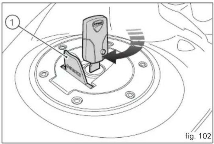
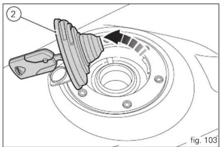
Seat lock
By operating the lock (1, fig. 104) the passenger seat can be removed to access the tool kit compartment and the rider seat to access the battery and other devices.
Removal of the seats
Insert the active or passive key into the lock (1) and rotate it clockwise until you hear the release click in the passenger seat.
To remove the passenger seat (2, fig. 105) lift up the front part and pull it forward to free the rear hook (3) on the bottom of the seat.
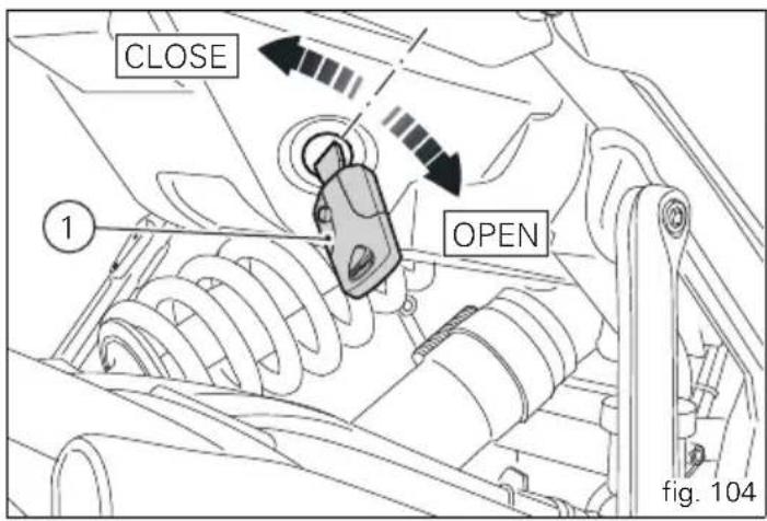

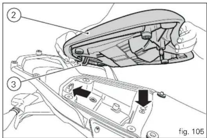

To remove the rider seat (4, fig. 106) remove the rear part from the pins (5) on the frame. Pull it backwards and at the same time push the front part of the rider seat downwards to unhook it from the pins (6, fig. 107) on the tank.
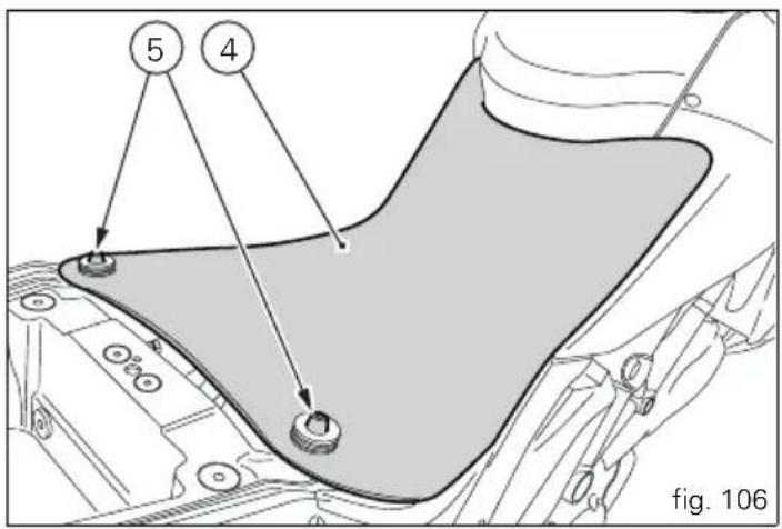
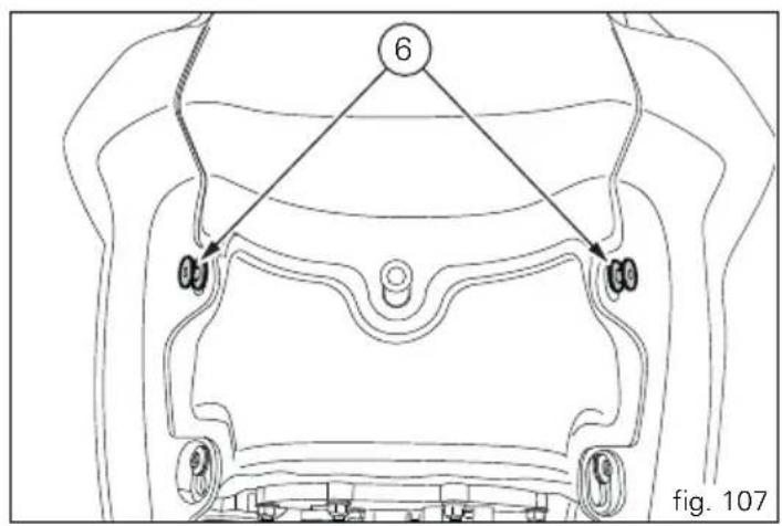
Refitting
Position the front part of the rider seat (4), with slots (7, fig. 108), in the pins (6, fig. 107) of the tank.
Push on the front end of the rider seat to move the pins (6) to the bottom of the slots (7).
Insert the rear part of the rider seat into the pins (5, fig. 106) of the frame.
Insert the rear hook (3, fig. 105) into the opening in the tail guard and lower the front part of the passenger seat (2) until you hear the pin click in the latch.
Make sure that the passenger seat is properly secured by gently pulling it upwards.
Remove key from the lock (1, fig. 104).
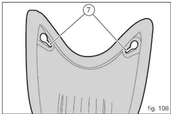

Side stand (fig. 109)

Important
Before lowering the side stand, check that the ground
is sufficiently even and firm.
Do not park on soft or pebbled ground or on asphalt melted by the sun heat and similar or the motorcycle may fall over. When parking on a slope, always park with the rear wheel on the downhill side.
To pull down the side stand, hold the motorcycle handlebars with both hands and push down on the thrust arm (1) with your foot until it is fully extended. Tilt the motorcycle until the side stand is resting on the ground.

Warning
Do not sit on the motorcycle when it is supported on
the side stand.
To raise the side stand to rest position (horizontal), tilt the motorcycle to the right and, at the same time, lift the stand (1) with your foot.
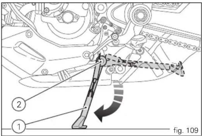

Note
Check for proper operation of the stand mechanism (two springs, one into the other) and the safety sensor (2) at regular intervals.

Note
It is possible to start the engine with side stand down and the gearbox in neutral. When starting the bike with a gear engaged, pull the clutch lever (in this case the side stand must be up).
Power outlet
The motorcycle has two power outlets to power the accessories. The outlets are protected by a 10 A fuse located in the rear fuse box.
The power outlets are positioned on the left (1, fig. 110) and right (2, fig. 111) sides of the motorcycle behind the passenger pedal support bracket.

Important
When the engine is off, do not leave accessories
connected to the power outlets for a long period of time as the motorcycle battery could run flat.
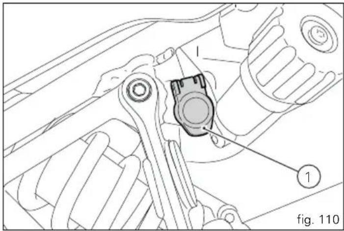
natural_image
Technical line drawing of a mechanical assembly with labeled components (no readable text or symbols)
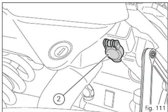

Adjusting the front fork
The front fork used on this motorcycle has rebound, compression and spring preload adjustment.
The settings are adjusted using external adjuster screws.
1) to adjust rebound damping (fig. 112);
2) to adjust spring preload (fig. 112);
3) to adjust compression damping (fig. 113).
Park the motorcycle in a stable position on its side stand. Turn the adjuster (1) on fork leg top with a flat screwdriver to adjust rebound damping.
Turn the adjusting screws (1 and 3) to adjust the dampening. Turn the screw all the way in to set the hardest damping (position "0"). Starting from this position, turning anticlockwise, you can count the turns.
To change preload of the spring inside each fork leg, turn the hex. adjuster (2, fig. 112) with a 22 mm hexagon wrench, starting from the fully open position (clockwise).
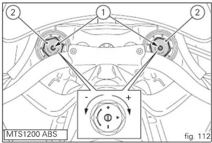
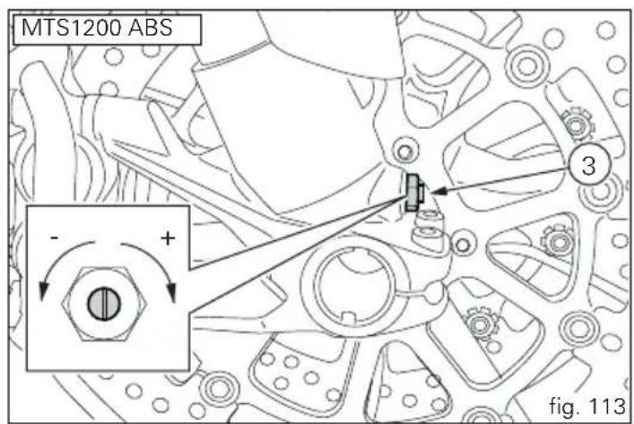
STANDARD factory setting is as follows:
Compression:
1 and a half turns;
Rebound:
2 turns.
Spring preload: FULLY OPEN (anticlockwise).

Important
Adjust both fork legs to same settings.
In the "S" model, the fork is adjusted by electric impulses sent by the instrument panel to the adjusters (fig. 114) inside the fork legs.
For fork adjustment, follow the description on page 60 "DES setting function (Ducati Electronic suspension)".
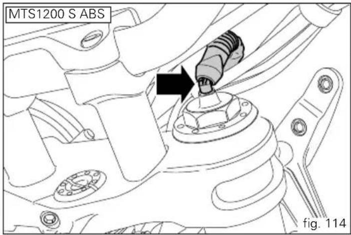


Adjusting the rear shock absorber
The rear shock absorber has external commands that enable you to adjust the setting to suit the load on the motorcycle. The adjuster (1, fig. 115) located on the lower connection holding the shock absorber to the swingarm adjusts the damping during the rebound phase (return).
The knob (2, fig. 115), located on the left side of the motorcycle, adjusts the preload of the shock absorber external spring.
The adjuster (3, fig. 116) located on the expansion reservoir of the shock absorber adjusts the damping during the compression phase.
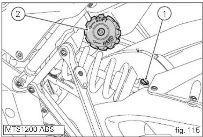
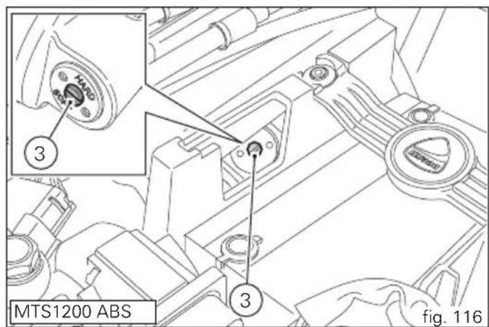
To access the adjuster (3, fig. 116) remove the rider seat and the cover (4, fig. 117) located to the side of the battery. The adjuster (3, fig. 116) can be turned through the hole in the battery support.
Turning the adjusters (1) and (3) or the knob (2) in a clockwise direction increases the damping or the preload; they decrease turning them in the opposite direction.
STANDARD setting; from fully closed (clockwise) loosen: adjuster (1) by 9 clicks;
knob (2) by 18 mm (max. 18 - min. 25 mm); adjuster (3) by 1.5 clicks.

Warning
The shock absorber is filled with gas under pressure and may cause severe damage if taken apart by unskilled persons.
When carrying a passenger and luggage, set the rear shock absorber spring to proper preload to improve motorcycle handling and keep safe clearance from the ground. It may also be necessary to adjust the rebound damping accordingly.
In the "S" model, the shock absorber is adjusted by electric impulses sent by the instrument panel to the adjusters (fig. 118) inside the shock absorber body.
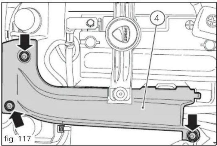
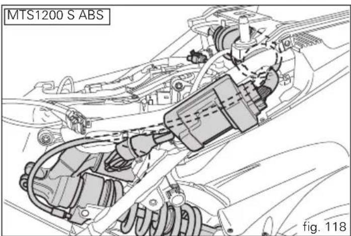
E
Motorcycle setup variation ("S" version only)
Motorcycle setup is the optimal result of tests carried out under different riding conditions by our technical staff.
The rider can set four different setup configurations on the instrument panel:
- Single passenger;
- Single passenger with luggage;
- Two passengers;
- Two passengers with luggage.
For each of these settings, four riding modes (SPORT, TOURING, URBAN and ENDURO) can be selected and within each of these, the initial settings for traction control (DTC), engine power and suspension dampening control can be modified.
To change the setup, proceed as described on page 52
"Riding Mode Customisation".

Single passenger

Single passenger with luggage

Two passengers

Two passengers with luggage
fig. 119
Directions for use
For the first 100 km use the brakes gently. Avoid sudden or prolonged braking. This will allow the friction material on the brake pads to bed in against the brake discs.
To allow all the mechanical moving parts in the motorcycle to adapt to one another, and to avoid shortening the life of the main engine components, it is advisable to avoid sudden acceleration and running the engine at high rpm for too long, especially uphill.
Furthermore, the drive chain should be inspected frequently. Lubricate as required.
Running-in recommendations
Maximum rpm (fig. 120)
Rotation speed for running-in period and during standard use (rpm):
1) up to 1000 km;
2) from 1000 to 2500 km.
Up to 1000 km
During the first 1000 km, keep an eye on the rev counter. It should never exceed:
5500÷6000 rpm.
During the first hours of riding, it is advisable to run the engine at varying load and rpm, though still within recommended limit.
To this end, roads with plenty of bends and even slightly hilly areas are ideal for a most efficient running-in of engine, brakes and suspension.
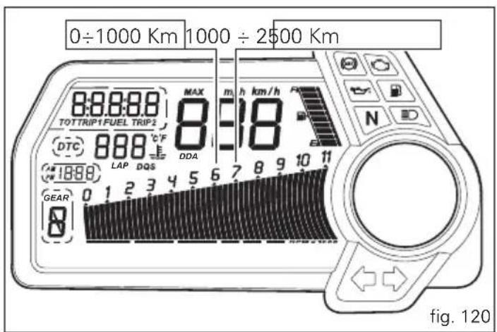

From 1000 to 2500 km
At this point, you can squeeze some more power out of your engine. However never exceed: 7000 rpm.

Important
Throughout the running-in period, be careful to stick to the recommended maintenance schedule and periodic service intervals indicated in the warranty booklet. Failure to follow these instructions releases Ducati Motor Holding S.p.A. from any liability whatsoever for any engine damage or shorter engine life.
Strict observance of running-in recommendations will ensure longer engine life and reduce the likelihood of overhauls and tune-ups.
Pre-ride checks

Warning
Failure to carry out these checks before riding, may
lead to motorcycle damage and injury to rider and passenger.
Before riding, perform a thorough check-up on your bike as follows:
FUEL LEVEL IN THE TANK
Check the fuel level in the tank. Fill tank if needed (page 140).
ENGINE OIL LEVEL
Check oil level in the sump through the sight
glass. Top up if needed (page 161).
Check coolant level in the expansion reservoir. Top up if needed (page 144).
TYRE CONDITION
Check tyre pressure and condition (page 159).
CONTROLS
Operate the brake, clutch, throttle and gear change controls (levers, pedals and twistgrip) to check that they function correctly.
LIGHTS AND INDICATORS
Make sure the lights, indicators and horn work properly.
Replace any burnt-out bulbs (page 153).
KEY-OPERATED LOCKS
Ensure that fuel filler plug (page 118) and seat (page 119) are firmly secured.
STAND
Make sure side stand operates smoothly and is in the correct position (page 122).
ABS light
After Key-On, the ABS light (10, fig. 3) stays on. When the vehicle speed exceeds 5 km/h; the light turns off to indicate that the ABS system is functioning properly.

Warning
In case of malfunction, do not ride the motorcycle and contact a Ducati Dealer or authorised Service Centre.

ABS device
Check that the front (1, fig. 121) and rear (2, fig. 122) phonic wheels are clean.

Warning
Clogged reading slots would compromise system
proper operation.
It is recommended to disable ABS system in case of muddy road surface because under this condition the system might be subject to sudden failure.

Warning
Prolonged rearing could deactivate the ABS system.
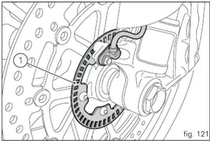
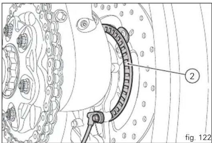
Engine on/off

Warning
Before starting the engine, become familiar with the tools you will need to use when riding (page 99).

Warning
Never start or run the engine indoors. Exhaust gases are toxic and may lead to loss of consciousness or even death within a short time.
In the presence of the active or passive key, perform a Key-On (turning on the "Hands free" system and all on-board electronic devices) by pushing the red switch (1, fig. 123), on the right side of the handlebar, downward.
The instrument panel will perform the initialisation and will control the onboard systems, turning on all lights in sequence, from the bottom to the top, for a few seconds. After this control, only the green light (2, fig. 124) and the red light must remain on.

Warning
The side stand must be fully up (in a horizontal position) as its safety sensor prevents engine start when down.
After Key-On, but with the engine not yet started, the system will perform a Key-Off automatically if the presence of the active key is not detected within 10 seconds.
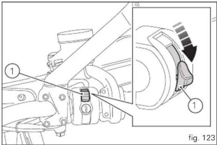
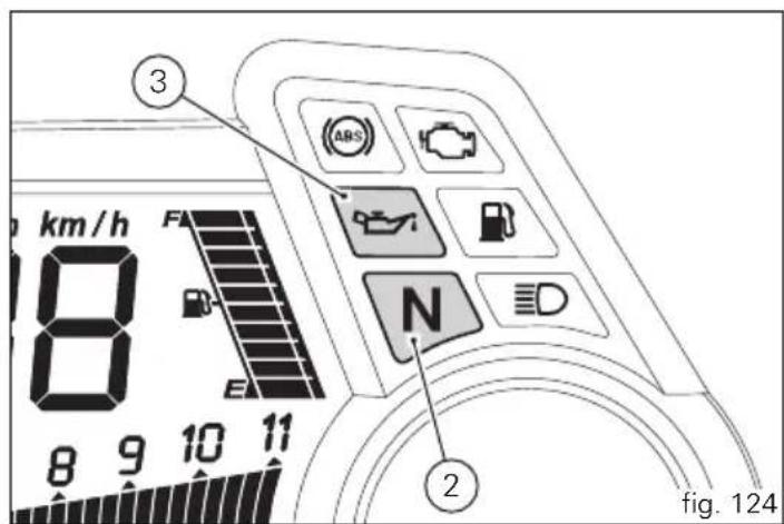


Note
It is possible to start the engine with side stand down and the gearbox in neutral. When starting the bike with a gear engaged, pull the clutch lever (in this case the side stand must be up).
Move the red switch (1) up to uncover the black button (4, fig. 125).
Push the button (4) to start the engine.

Important
Do not rev up the engine when it is cold. Allow some time for the oil to warm up and reach all points that need lubricating.
The red oil pressure warning light should go out a few seconds after the engine has started.
The engine will shut off by turning the red key (1, fig. 125) on the handlebar to RUN OFF.

Note
To turn on the "Hands free" system and all electronic onboard systems, refer to page 100 "Hands Free System".
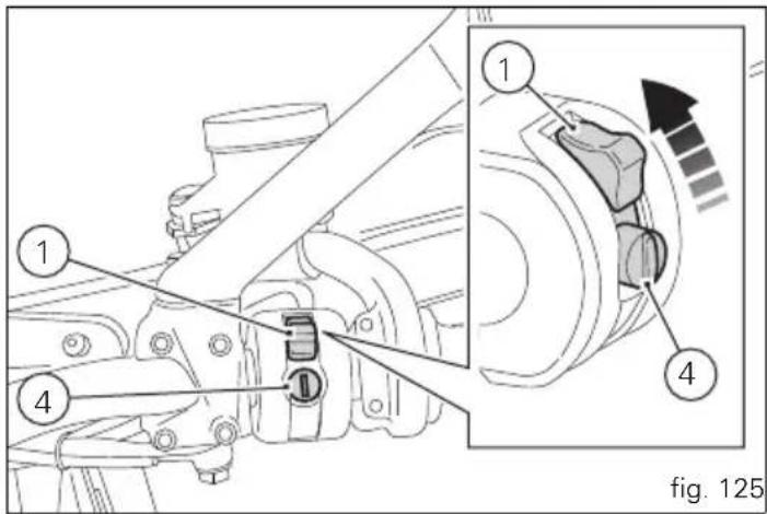
Moving off
1) Disengage the clutch by squeezing the clutch lever.
2) Push down the gear change lever firmly with the tip of your foot to engage first gear.
3) Raise the engine revs by turning the throttle twistgrip while gradually releasing the clutch lever. The motorcycle will start moving.
4) Release the clutch lever completely and accelerate.
5) To shift up, close the throttle to slow down engine, disengage the clutch, lift the gear change lever and let go of clutch lever.
To shift down, proceed as follows: release the twistgrip, pull the clutch control lever, shortly speed up to help gears synchronise, shift down (engage next lower gear) and release the clutch.
The controls should be used correctly and timely: when riding uphill, do not hesitate to shift down as soon as the motorcycle starts to slow down, so you will avoid stressing the engine and the motorcycle abnormally.

Important
Avoid sudden acceleration, as this may lead to
misfiring and transmission snatching. The clutch lever should not be held in longer than necessary after a gear is engaged, otherwise friction parts may overheat and wear out.

Warning
Prolonged rearing could deactivate the ABS system.
Braking
Slow down in time, shift down to engine-brake first and then brake applying both brakes. Pull the clutch lever before stopping the motorcycle, to avoid sudden engine stop.


ABS system
Using the brakes correctly under adverse conditions is the hardest – and yet the most critical - skill to master for a rider. Braking is one of the most difficult and dangerous moments when riding a two wheeled vehicle: the possibility of falling or having an accident during this difficult moment is statistically higher than any other moment. A locked front wheel leads to loss of traction and stability, resulting in loss of control.
The Anti-Lock Brake System (ABS) has been developed to enable riders to use the vehicles braking force to the fullest possible amount in emergency braking or under poor pavement or adverse weather conditions.
ABS uses hydraulics and electronics to limit pressure in the brake circuit when a special sensor mounted to the wheel signals the electronic control unit that the wheel is about to lock up.
This avoids wheel lockup and preserves traction. Pressure is raised back up immediately and the control unit keeps controlling the brake until the risk of a lockup disappears.
Normally, the rider will perceive ABS operation as a harder feel or a pulsation of the brake lever and pedal.
The front and rear brakes use separate control systems, meaning that they operate independently. Likewise, the ABS is not an integral braking system and does not control both the front and rear brake at the same time.
If desired, the system can be deactivated from the instrument panel, using the "ABS disabling function".

Warning
Use both the brake lever and the brake pedal forive braking.
Using only one of the brakes will give you less braking power. Never use the brake controls harshly or suddenly as you may lock the wheels and lose control of the motorcycle. When riding in the rain or on slippery surfaces, braking capacity is significantly reduced. Always use the brakes very gently and carefully when riding under these conditions. Any sudden manoeuvres may lead to loss of control. When tackling long, high-gradient downhill road tracts, shift down gears to use engine braking. Apply one brake at a time and use brakes sparingly. Keeping the brakes applied continuously causes the friction material to overheat and dangerously reduces braking effectiveness. Underinflated or overinflated tyres reduce braking efficiency, handling accuracy and stability in a bend.
Stopping the motorcycle
Reduce speed, shift down and release the throttle twistgrip. Shift down to engage first gear and then neutral. Apply the brakes and bring the motorcycle to a complete stop. Turn off the engine moving the red switch downward (1, fig. 127).
Parking
Park the stopped motorcycle on the side stand.
Turn the handle completely to the left or right.
If this operation is performed within 60 seconds of turning off the engine, the message "Waiting for lock" (fig. 126) will appear on the circular display of the instrument panel for approx. 5 seconds.
If you want to enable the steering lock, move the red switch (1, fig. 127) downward during this interval.
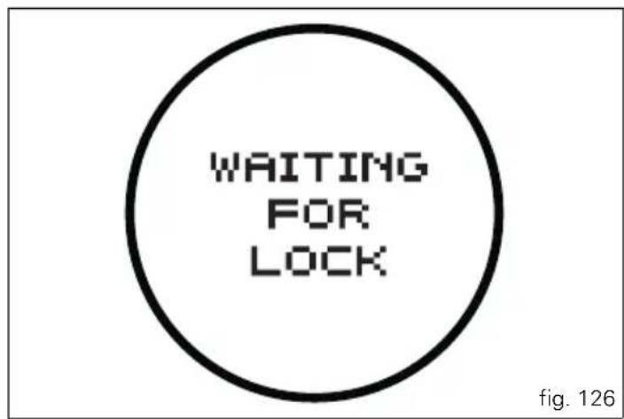

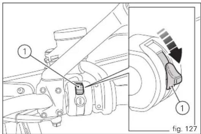
If the steering lock was enabled correctly, the locked steering indication (fig. 128) will appear on the circular display of the instrument panel for 5 seconds.
The steering lock disables at Key-On.
If the "Hands free" system was not able to release the steering, an error message (fig. 129) will appear on the display.
In this case, it is recommended to turn the vehicle off and on (Key-Off / Key-On) holding the handlebar pressed down to the end stop. If the signal remains (and the steering does not "release") contact an Authorised Ducati Service Centre.
In order to make the motorcycle visible at night or in poorly illuminated areas, the "Parking" function can be activated within 60 seconds of turning off the vehicle by turning on the front and rear parking lights.

fig. 128
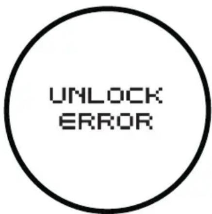
fig. 129
Press (2, fig. 130) for at least 3 seconds: the indication of the activated function (fig. 131) will appear on the circular display of the instrument panel for 5 seconds and the lights will remain on for 2 hours. After this period of time, they will turn off automatically.

Note
If there is a sudden interruption in the battery voltage during the "Parking" function, the instrument panel will disable this function when the voltage is restored.

Important
The frequent use of this function can considerably reduce the battery charge; it is recommended to use this function only when necessary.

Warning
The exhaust system may still be hot even after engine is switched off; take special care not to touch the exhaust system with any part of your body and do not park the motorcycle next to inflammable material (wood, leaves, etc.).

Warning
Using padlocks or other locks designed to prevent motorcycle motion, such as brake disc locks, rear sprocket locks, and so on is dangerous and may impair motorcycle operation and affect the safety of rider and passenger.
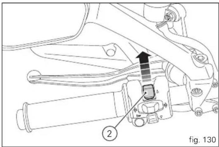

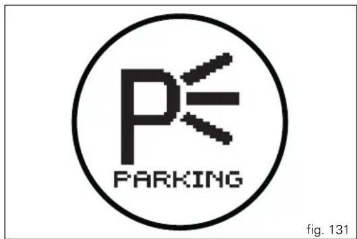

Refuelling (fig. 132)
Never overfill the tank when refuelling. The fuel level should always be below the rim of the filler recess.

Warning
Use low-lead fuel with 95 octane rating at origin
minimum (see "Top-ups" table, page 170).
Check that no fuel is trapped in the filler cap recess.
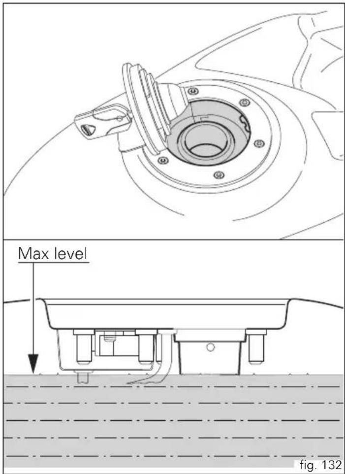
Tool kit and accessories (fig. 133)
The compartment under the passenger seat (1) holds: an Owner's manual and tool kit (2) including:
- 1 90° needle with rubber scraper;
- 2 rubber cylinders for punctures;
- 2 high pressure spray cans;
- 2 valve adaptors (if not provided with the spray cans);
- 1 5 mm Allen wrench x gravel guard;
- 1 10 mm Allen wrench x eccentric clamp;
- 1 pin wrench for the eccentric;
- 1 extension per pin wrench, 10 mm Allen wrench, screwdriver;
- 1 chain tension gauge;
- 1 Phillips screwdriver or 10 mm wrench for battery;
To access the compartment remove the passenger seat.
The following are also provided as standard:
- front semi-mudguard kit;
- long rear mudguard kit.
Front semi-mudguard kit (fig. 134)

Important
To fit the from semi-mudguard kit, ALWAYS contact a
Ducati Dealer or Authorised Service Centre.
Remove the pipe grommet (1, fig. 134) unscrewing the two screws (2, fig. 134).
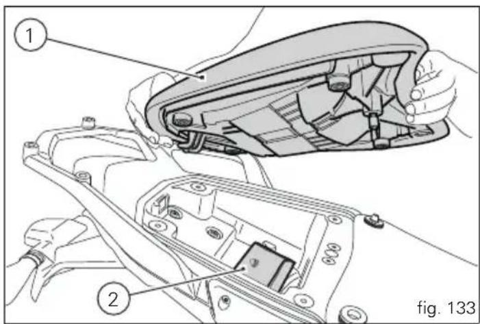
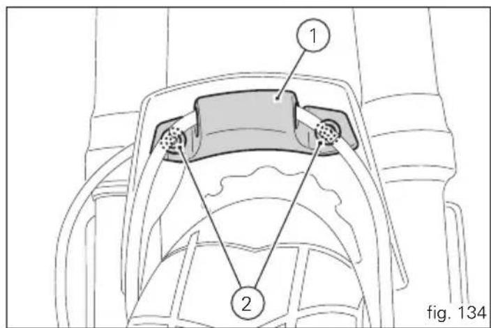

Position the front semi-mudguard kit (3) on the front mudguard, housing the front brake pipe (4) and the front phonic wheel cable (5) as shown in the figure (fig. 136). Fasten the slot (A) in the fissure in the front mudguard (1) and start the two previously removed screws (2). Tighten the two screws (2) to a torque of 3.5Nm ± 10% .
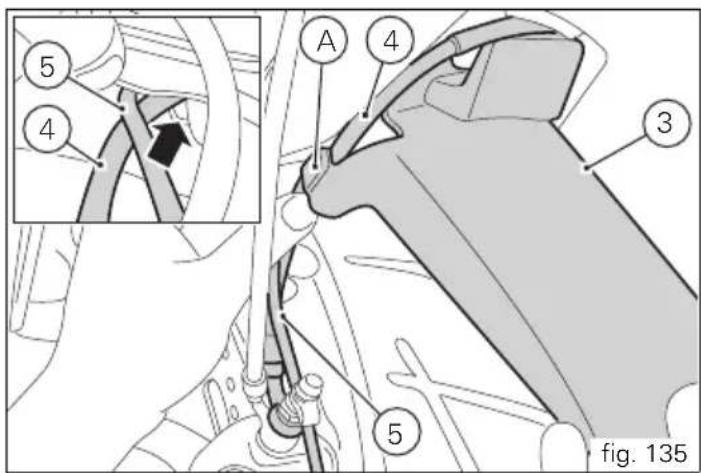
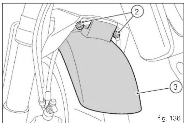
Long rear mudguard kit

Important
To fit the long rear mudguard kit, ALWAYS contact a
Ducati Dealer or Authorised Service Centre.
Remove the rear mudguard (1) unscrewing the three screws (2).
Position the long rear mudguard kit (3) on the swingarm, starting the previously removed screws (2).
Tighten the screws (2) to a torque of 5 Nm ± 10%.
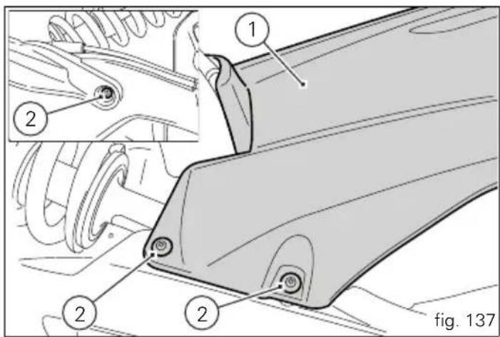

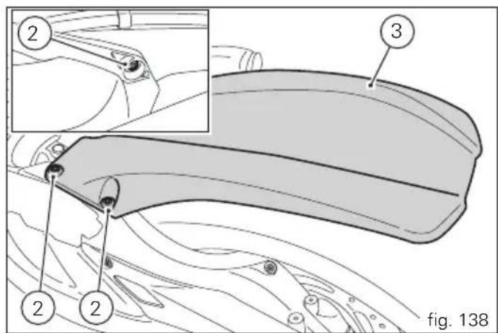

Main maintenance operations
Warning This operation must be carried out with the engine cold and with the motorcycle vertical and level.
Checking and topping up coolant level
Check the coolant level in the expansion reservoir on the right-hand side of the headstock.
Steer the handlebar completely to the left and check that the level is between the MIN and MAX marks on the side of the expansion reservoir.
Top up if the level is below the MIN mark.
Unscrew the filler plug (1) and add a mixture consisting of water and antifreeze SHELL Advance Coolant or Glycoshell (35÷ 40%) of the volume) up to the MAX level.
Refit the plug (1).
This type of mixture ensures the best operating conditions (the coolant starts to freeze at -20 °C/-4 °F).
Cooling circuit capacity: 4.10 cu. dm (litres).
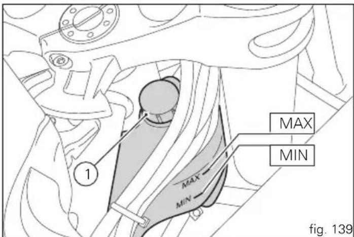
Checking brake and clutch fluid level
The level must not go below the MIN mark shown on the respective reservoirs (fig. 140 shows the front and rear brake fluid reservoirs, fig. 141 shows the clutch fluid reservoir). If the level is too low, air can get into the circuit, thus impairing the efficiency of the system.
Brake and clutch fluid must be topped up and changed at the intervals specified in the scheduled maintenance chart reported in the Warranty Booklet; please contact a Ducati Dealer or authorised Service Centre.

Important
It is recommended all brake and clutch lines be
changed every four years.
Brake system
If you find exceeding play on brake lever or pedal and brake pads are still in good condition, contact your Ducati Dealer or authorised Service Centre to have the system inspected and any air drained out of the circuit.

Warning
Brake and clutch fluid can damage paintwork and
plastic parts, so avoid contact. Hydraulic fluid is corrosive and can cause damage and injuries. Never mix fluids of different qualities.
Check that the seals are in good condition.
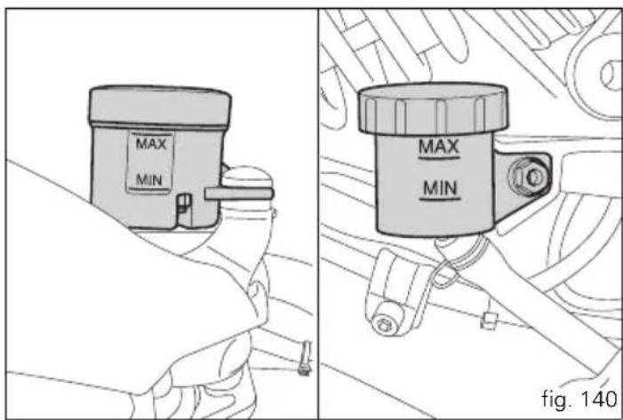

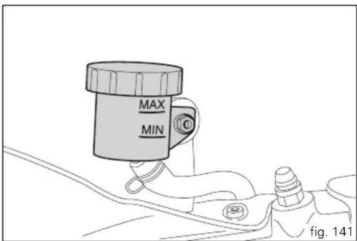

Clutch system
If the control lever has exceeding play and the transmission snatches or jams as you try to engage a gear, it means that there might be air in the circuit. Contact your Ducati Dealer or authorised Service Centre to have the system inspected and air drained out.

Warning
The clutch fluid level in the reservoir tends to rise as the friction material on the clutch plates wears out. Do not exceed the specified level (3 mm above the minimum level).
Checking brake pads for wear
To facilitate inspection without removing the pads from the callipers, brake pads have a wear mark. If the grooves in the pad friction material are still visible, the pad is still in good condition.
The pads must be replaced when approx. 1 mm of friction material (fig. 142 and fig. 143) can be seen through the opening between the callipers.

Important
Have the brake pads replaced at a Ducati Dealer or
authorised Service Centre.
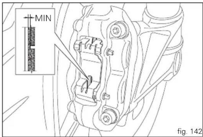
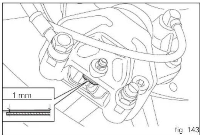

Lubricating cables and joints
Check the outer sheath of the throttle control and cold start lever cables for damage at regular intervals. The outer plastic cover should not be flattened or cracked. Operate the controls to make sure the inner cables slide smoothly inside the outer sheath: if you feel any friction or catching, have the cable replaced by a Ducati Dealer or Authorised Service Centre.
To avoid this kind of problem with the throttle cable, unscrew the two retaining screws (1, fig. 144) to open the case and then the grease cable ends and pulley (2, fig. 145) with SHELL Advance Grease or Retinax LX2 grease.

Warning
Close the twistgrip housing carefully, inserting the
cable in the pulley.
Refit the housing and tighten the screws (1) to 10 Nm.
To ensure smooth operation of the side stand pivot, remove dirt and apply SHELL Alvania R3 grease to all friction points.
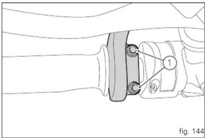
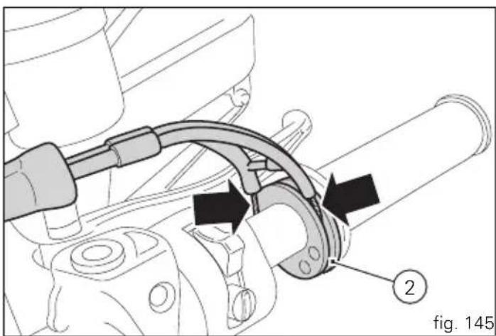
natural_image
Mechanical assembly diagram showing a clamping device with two labeled parts (2 and 1), no readable text or symbols present.Adjusting throttle control free play
The throttle twistgrip must have free play of 1.5 - 2.0 mm in all steering positions, measured on the outer edge of the twistgrip. If necessary, adjust it using the adjusters (1 and 2, fig. 146) located on the headstock on the left-hand side of the vehicle.
Adjuster (1) is for throttle opening, and adjuster (2) is for throttle closing.
Slip the rubber gaiters off the adjusters and loosen the counter nuts (3). Adjust both adjusters by the same amount: turn clockwise to increase free play and anticlockwise to reduce free play. When finished, tighten the counter nuts (3) and refit the rubber gaiters to the adjusters.
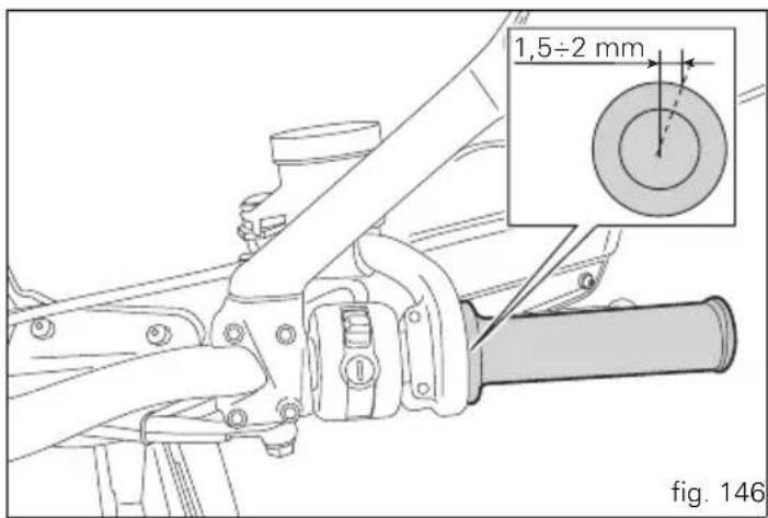
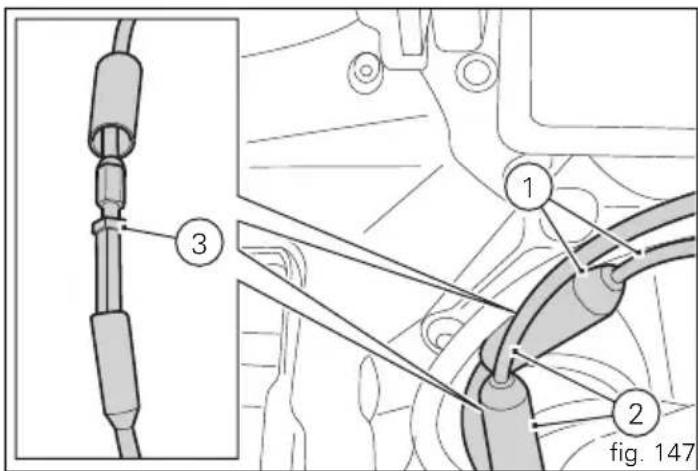

Charging the battery (fig. 148)
Before charging the battery, it is recommended to remove it from the motorcycle.
Remove the rider seat, unscrew the screw (1) and remove the bracket (2). Always disconnect the black negative terminal (-) first, then the red positive terminal (+).

Warning
The battery produces explosive gases: keep it away
from heat sources and flames.
Charge the battery in a well-ventilated area.
Connect the battery charger leads to the battery terminals: red to the positive terminal (+), black to the negative terminal (-).

Important
Connect the battery to the charger before switching it
on; failure to do so can result in sparking at the battery terminals, which could ignite the gases inside the cells.
Always connect the red positive terminal (+) first.
Reinstall the battery on its mount and secure the bracket (2) with the screw (1). Apply some grease on the fastening screws to improve conductive capacity and connect the terminals.

Warning
Keep the battery out of the reach of children.
Charge the battery at 0.9 A for 5÷10 hours.
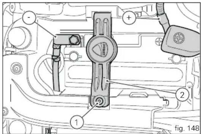
Checking drive chain tension (fig. 149)

Important
Have chain tension adjusted by a Ducati Dealer or rised Service Centre.
Measure chain tension at the centre of the lower section, with the motorcycle on the side stand: lower the chain by pressing down on it only with your finger, release it and measure the distance (A) between the centre of the chain pins and the aluminium section of the swingarm. It must be: A = 35 ÷ 37 mm.

Warning
Correct tightening of screws (1, fig. 150) is critical to and passenger safety.

Important
Improper chain tension will lead to early wear of mission parts.
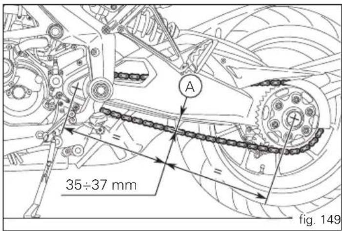

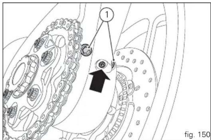

To access the screws (1), remove the rear gravel guards (2, fig. 150) and chain guard (3), unscrewing the three screws (4).
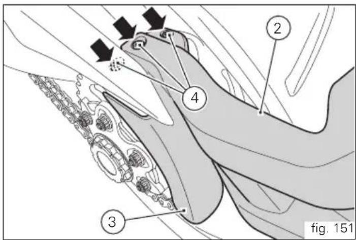
Chain lubrication
The chain fitted on your motorcycle has O-rings that keep dirt out of and lubricant inside the sliding parts.
So as not to damage these seals when cleaning the chain, use special solvents and avoid aggressive washing with high-pressure steam cleaners.
After cleaning, blow the chain dry with compressed air or wipe with an absorbent material, then lubricate each link with SHELL Advance Chain or Advance Teflon Chain.

Important
Using non-specific lubricants may cause severe
damage to the chain and the front and rear sprockets.
Replacing the high and low beam bulbs
Before replacing a burnt-out bulb, make sure that the new bulb complies with the voltage and wattage specified in the "Wiring diagram", page 176. Always test the new bulb before refitting any parts you have removed.
fig. 152 shows the locations of the low beam bulbs (LO), high beam bulbs (HI) and the parking light bulb (1).
Headlight
To access the right or left side headlight bulbs, remove the corresponding panel, proceeding as follows.

Note
The figures show the replacement of the right side headlight bulbs: the procedure is the same for the left side.
Remove the panel cover (2, fig. 153).
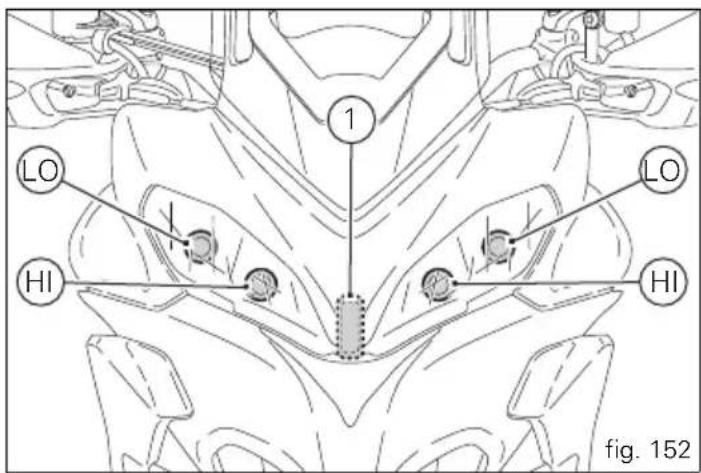
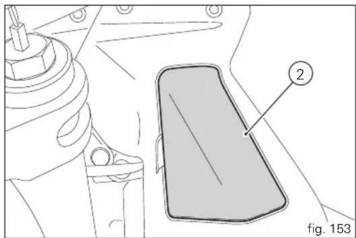
natural_image
Technical line drawing of a mechanical component with a highlighted rectangular area and numbered label (2), no readable text or symbols beyond the label.
Unscrew the four screws (3, fig. 154) that fasten the panel (4) to top fairing.
Remove the panel (4), lifting the rear part to unhook the tabs from the slots (A, fig. 155) in the top fairing. Detach the connector (5) from the bulb holder (6). Turn the bulb holder with the burnt-out bulb anticlockwise and remove it. Replace the bulb with an identical one.

Note
Be careful to hold the new bulb at the base only. Never
touch the transparent body with your fingers or it will blacken resulting in reduced bulb brilliancy.
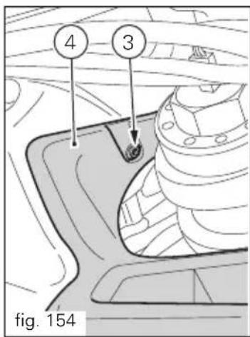
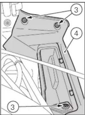
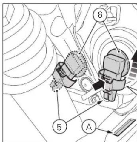
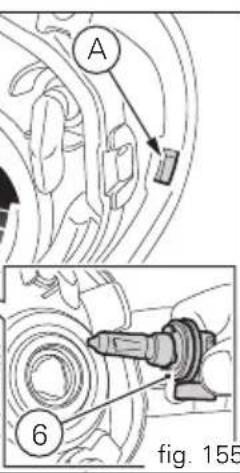
Refitting
When refitting, turn the bulb holder (6) clockwise to lock it into the headlight body.
Reconnect the connector (5) and refit the structures that were removed being careful to insert the tabs (B, fig. 156) into the slots (A, fig. 155) made in the top fairing.

Note
To replace the parking light LED bulb, contact an
Authorised Ducati Service Centre.
Rear turn signals (fig. 157)
Remove the screw (1) and detach the glass (2) from the indicator body holder.
The bulb has a bayonet-type end fitting: to remove it, push it in and turn it counter-clockwise. Push in the new bulb and turn it clockwise until it clicks into place. Refit the cup (2) by inserting the tab into the corresponding slot in the turn signal support.
and tighten the screw (1).
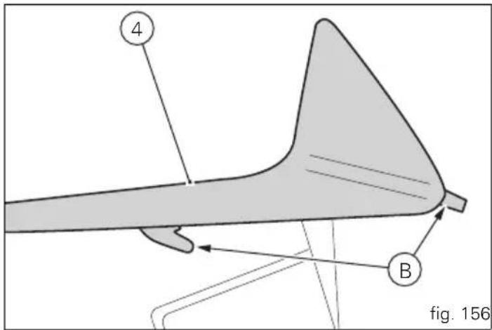
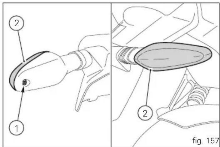

Number plate light (fig. 158)
To access the bulb in the number plate light open the number plate lens (3), pull the bulb (4) out of the holder and replace it.
Beam setting (fig. 159)
When checking beam setting, put the motorcycle upright. Tyres should be inflated at the correct pressure and one person should be sitting astride the motorcycle, keeping it at right angles to its longitudinal axis. Place the motorcycle opposite a wall or a screen, 10 meters apart from it, Draw a horizontal line on the wall at the height of the centre of the headlight and a vertical one in line with the longitudinal axis of the motorcycle.
If possible, perform this check in dim light.
Switch on the low beam headlight.
The height of the upper limit between the dark area and the lit area must not be more than nine tenths of the height of the centre of the headlamp from the ground.

Note
The procedure described here is in compliance with the Italian Standard establishing the maximum height of the light beam.
Owners in other countries should adapt this procedure to the regulations in force in the country where the motorcycle is used.
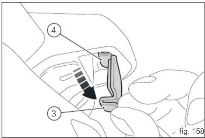
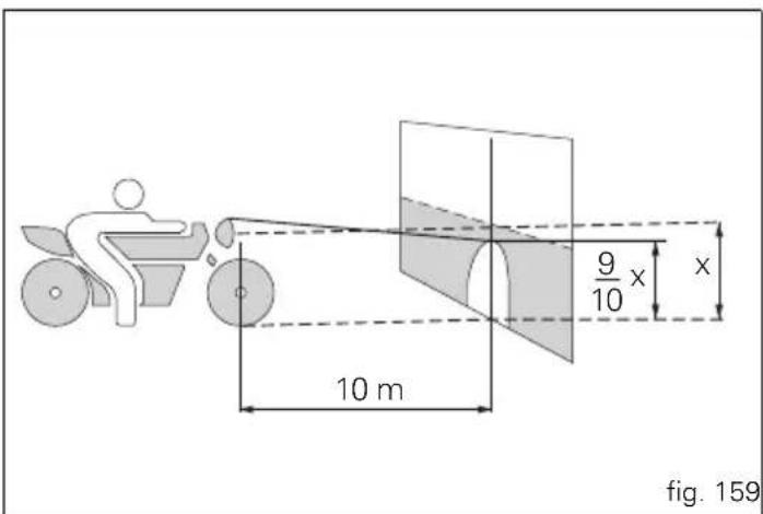
The height of the headlight beam can be adjusted using the adjusting screws (1, fig. 160) located at the bottom on the sides of the headlight. Turning the screw (1) of the headlight clockwise, the light beam will move downwards: turning it in the opposite direction, will move it upwards. The side position of the headlight can be adjusted using the adjusting screws (2) located at the centre on the upper part of the headlight. Turning the screws (2) on the left side of the headlight clockwise, the light beam will move to the right: turning it in the opposite direction, will move it to the left. To move the light beam in the same manner, turn the screw (2) on the right side of the headlight, inverting the direction of rotation.

Warning
The headlight might fog up if the vehicle is used under
the rain or after washing.
Switch headlight on for a short time to dry up any condensate.
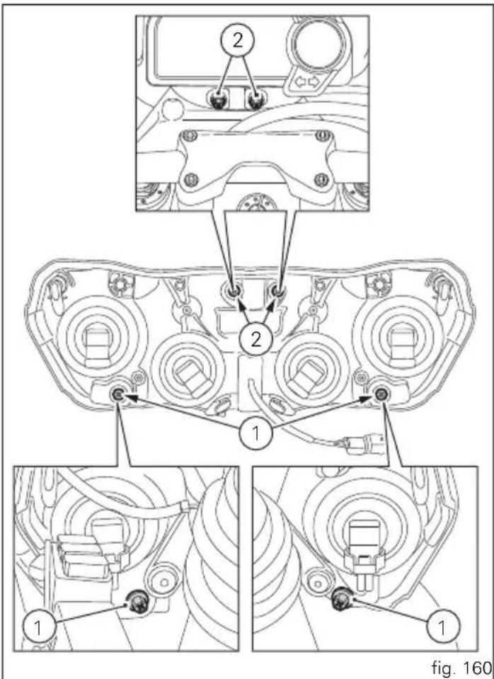

Rear-view mirror adjustment (fig. 161)
The rear-view mirror can be adjusted manually by pressing points (A).
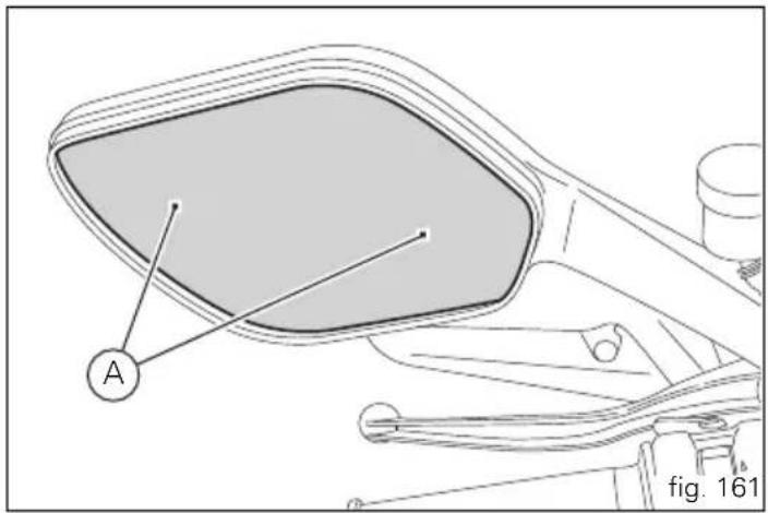
Tubeless tyres
Front tyre pressure:
2.50 bar (rider only) - 2.9 bar (with passenger and/or bags)
Rear tyre pressure:
2.50 bar (rider only) - 2.9 bar (with passenger and/or bags) As tyre pressures are affected by changes in temperature and altitude; check and adjust them whenever you are riding in areas where there are large variations in temperature or altitude.

Important
Check and adjust the pressures with the tyres cold.
To prevent distortion of the front wheel rim, increase tyre pressure by 0.2 ÷ 0.3 bar when riding on bumpy roads.
Tyre repair or change (Tubeless tyres)
With minor punctures, tubeless tyres take a long time to deflate, as they tend to hold the air inside. If you find low pressure on one tyre, check the tyre for punctures.

Warning
Punctured tyres must be renewed.
Replace with tyres of the original brand and type.
Be sure to tighten the valve caps securely to avoid leaks when riding. Never fit tyres with inner tubes, as these can cause the tyre to burst suddenly, with possibly serious consequences for the rider and passenger.
After renewing a tyre, the wheel must be balanced.

Important
Do not remove or alter the position of the wheel balancing weights.

Note
Have the tyres replaced at a Ducati Dealer or authorised Service Centre. Correct removal and installation of the wheels is essential.
as some parts of the ABS (such as sensors and phonic wheels) are mounted to the wheels and require specific adjustment.


Minimum tread depth
Measure tread depth (S, fig. 162) at the point where tread is most worn down.
It should not be less than 2 mm, and in any case not less than the legal limit.

Important
Visually inspect the tyres at regular intervals for cracks and cuts, especially on the side walls, and bulges or large stains that indicate internal damage. Replace them if badly damaged.
Remove any stones or other foreign bodies stuck in the tread.
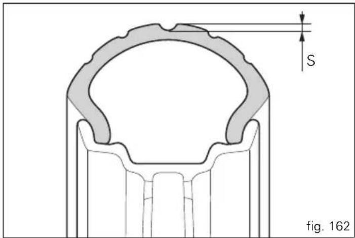
Checking engine oil level (fig. 163)
Check the engine oil level through the sight glass (1) on the clutch cover. When checking oil level, the motorcycle should be perfectly upright and the engine cold. The oil level should be between the two marks next to the sight glass. If level is low, top up with SHELL Advance Ultra 4 engine oil. Remove the filler plug (2) and top up to correct level. Replace the filler cap.

Important
Engine oil and oil filters must be changed by a Ducati
Dealer or authorised Service Centre at the intervals specified in the scheduled maintenance table reported in the Warranty Booklet.
Viscosity
SAE 15W-50
The other viscosity values shown in the table can be used if the local average temperature falls within the limits specified for that oil viscosity.
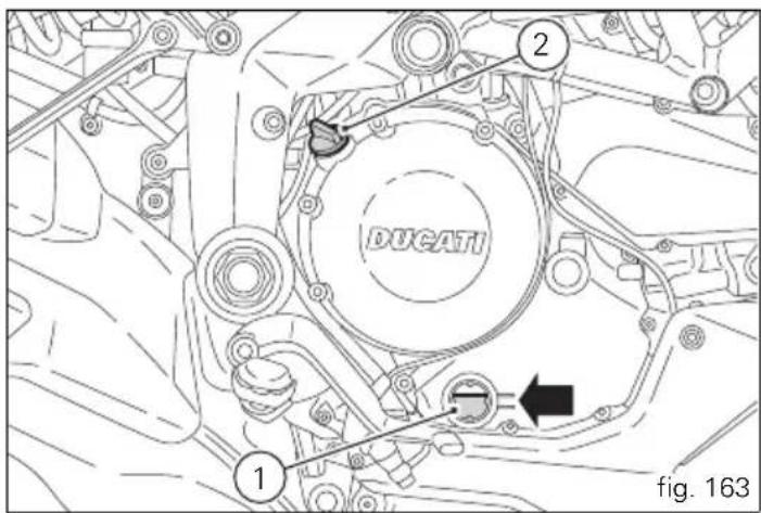

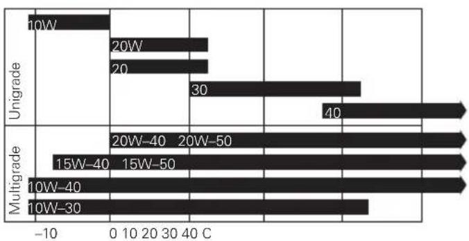
bar
| Category | Value | |---|---| | Unigrade 10W | -5 | | Unigrade 20W | 40 | | Unigrade 20 | 40 | | Unigrade 30 | 40 | | Multigrade 15W-40 | 40 | | Multigrade 15W-50 | 40 | | Multigrade 10W-40 | 40 | | Multigrade 10W-30 | 40 |
Cleaning and replacing the spark plugs (fig. 164)
Spark plugs are essential to smooth engine running and should be checked at regular intervals.
The condition of the spark plugs provides a good indication of how well the engine is running.
Have the spark plugs inspected or replaced at an Ducati Dealer or Authorised Service Centre; they will check the colour of the ceramic insulator of the central electrode (1): an even brown colour is a sign that the engine is in good running order.

Note
Inspect the centre electrode for wear and check spark plug gap, which should be:
0.8÷0.1 mm.

Important
A gap outside the specified limits will adversely affect engine performance and may lead to difficult starting or erratic idling.
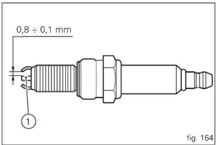
General cleaning
To preserve the finish of metal parts and paintwork, wash and clean your motorcycle at regular intervals, anyway according to the road conditions you ride in. Use specific products, where possible biodegradable. Avoid aggressive detergents or solvents.
Use only water and neutral soap to clean the Plexiglas and the seat.

Important
Do not wash your motorcycle immediately after use, as marks can form due to evaporation of the water on hot surfaces. Never clean the motorcycle using hot or high pressure water jets. Cleaning the motorcycle with a high pressure water jet may lead to seizure or serious faults in the front fork, wheel hub assembly, electrical system, headlight (fogging), front fork seals, air inlets or exhaust silencers, with consequent loss of safety.
Clean off stubborn dirt or exceeding grease from engine parts using a degreasing agent. Be sure to avoid contact with drive parts (chain, sprockets, etc.) Rinse with warm water and dry all surfaces with chamois leather.

Warning
There may be loss of braking efficiency immediately after washing the motorcycle. Never grease or lubricate the brake discs. This will cause loss of braking efficiency. Clean the discs with an oil-free solvent.

Warning
The headlight might fog up due to washing, rain or moisture.
Switch headlight on for a short time to dry up any condensate.
Carefully clean the phonic wheels of the ABS so to ensure system efficiency. Do not use aggressive products so to avoid damaging the phonic wheels and the sensors.
E
Storing the bike away
If the motorcycle is to be left unridden over long periods, it is advisable to carry out the following operations before storing it away:
clean the motorcycle;
empty the fuel tank;
pour a few drops of engine oil into the cylinders through the spark plug bores, then turn the engine over by hand a few times to form a protective film of oil on the inner walls of the cylinder;
place the motorcycle on a service stand;
disconnect and remove the battery.
If the motorcycle has been left unused for more than a month, the battery should be checked and recharged if necessary.
Protect the motorcycle with a specific motorcycle cover that will not damage the paintwork or retain moisture.
This type of motorcycle cover is available from Ducati
Performance.
Important notes
Some countries, such as France, Germany, Great Britain, Switzerland, etc. have compulsory emission and noise standards that include mandatory inspections at regular intervals.
Periodically carry out the required checks and renew parts as necessary, using Ducati original spare parts, in compliance with the regulations in the country concerned.
Scheduled maintenance chart
E
Operations to be carried out by the dealer
| List of operations to be performed at 1000 km |
| Reading of the error memory with DDS on the engine control units, vehicle and ABS |
| Change the engine oil |
| Change the engine oil filter |
| Check the indicators and lighting |
| Check the safety devices (side stand switch, clutch lever switch, right switch engine stop switch and gear position sensor) |
| Check the battery charge level |
| Clean the engine oil intake filter |
| Checking the coolant level |
| Check the brake and clutch fluid levels |
| Check brake discs and pad wear |
| Check tyre pressure and wear |

| List of operations to be performed at 1000 km |
| Check the drive chain tension and lubrication |
| Check the freedom of movement of the side and central stand (if installed) |
| Check the tightening of the safety components (ex. wheel disc nuts, brake callipers, sprocket tightening) |
| Check rubbing points, clearance and freedom of movement of the flexible cables and electric wiring in view |
| Road test of the motorcycle, testing the safety devices (ex. ABS) |
| Fill out that the service was performed in the Warranty Certificate |
Operations to be carried out by the dealer
| List of operations to be performed every 12000 km / year (first limit reached) |
| Reading of the error memory with DDS on the engine control units, vehicle and ABS |
| Change the engine oil |
| Change the engine oil filter |
| Check and/or adjust valve clearance (only every 24000 km) |
| Replace the timing belts (only every 24000 km/60 months) |
| Replace the spark plugs (only every 24000 km) |
| Replace the air filter (only every 24000 km) |
| Replace the front fork oil (only every 24000 km) |
| Replace the coolant (only every 24000 km) |
| Check the indicators and lighting |
| Check the safety devices (side stand switch, clutch lever switch, right switch engine stop switch and gear position sensor) |
| Check the battery charge level |
| Checking the coolant level |
| Check the brake and clutch fluid levels |
| Check brake discs and pad wear. |
| Check tyre pressure and wear |
| Check the drive chain tension and lubrication |
| Check final drive wear |
| Check and lubricate the rear wheel shaft (only every 24000 km) |

| List of operations to be performed every 12000 km / year (first limit reached) |
| Check the freedom of movement of the side and central stand (if installed) |
| Check the tightening of the safety components (ex. wheel disc nuts, brake callipers, sprocket tightening) |
| Check rubbing points, clearance and freedom of movement of the flexible cables and electric wiring in view |
| Road test of the motorcycle, testing the safety devices (ex. ABS) |
| Fill out that the service was performed in the Warranty Certificate |
Operations to be carried out by the customer
| List of operations to be performed every 1000 km |
| Check the level of the engine oil |
| Adjust chain tension |
Technical data
Carrying full load: 430 kg.
Overall dimensions (mm) (fig. 165)
Weights
Weight in running order without fluids and battery 192 kg.
Warning Failure to ob
Failure to observe weight limits could result in poor handling and impair the performance of your motorcycle, and you may lose control of the vehicle.
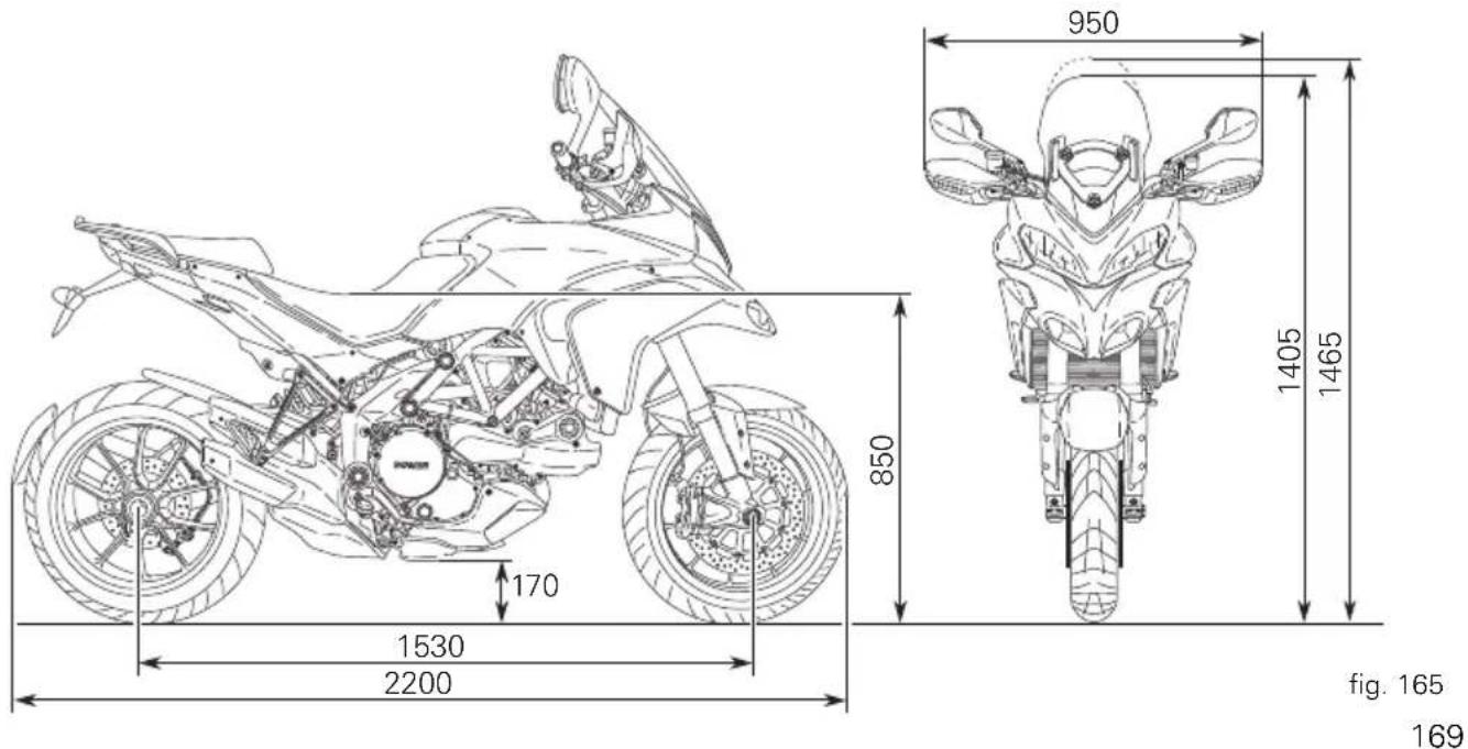

TOP-UPS TYPE
| Fuel tank, including a reserve of 4 cu. dm (litres) | Unleaded fuel with 95 fuel octane rating (at least) | 20,0 cu. dm (litres) |
| Lubrication circuit SHELL - Advance Ultra 4 4.10 cu. dm (litres) | ||
| Front/rear brake and clutch circuits Special hydraulic fluid SHELL Advance Brake Dot 4 | — | |
| Protection for electrical contacts SHELL - Advance Contact Cleaner spray for electrical systems | — | |
| Front fork SHELL - Advance Fork 7.5 or Donax TA 170 mm (per fork leg) (*) | (MTS1200 S ABS)720 cc (per fork leg) (*) (MTS1200 S ABS) | |
| Cooling system Antifreeze SHELL - Advance Coolant or Glycoshell 35÷40% + water | 2.3 cu. dm (litres). | |
(*) The value refers to the air column between the free surface of the oil and the end of the sleeve, with the latter fully lowered and without the preload pipe and spring inside the fork leg.

Important
Do not use additives in fuel or lubricants.
Engine
Twin cylinder, four-stroke, 90° "L" type, longitudinal.
Bore, mm:
106
Stroke, mm:
67.9
Total displacement, cu. cm:
1198.4
Compression ratio:
11.5±0.5:1
Max power at crankshaft (95/1/EC), kW/HP:
110.3 kW/150 HP at 9250 rpm
Max torque at crankshaft (95/1/EC):
12.1 kgm/118.7 Nm at 7500 rpm
Maximum rpm:
10700 rpm

Important
Do not exceed the specified rpm limits in any running
conditions.
Timing system
DESMODRÖMIC (type) with four valves per cylinder, operated by eight rocker arms (4 opening rockers and 4 closing rockers) and two overhead camshafts. It is operated by the crankshaft through spur gears, belt rollers and toothed belts.
Desmodromic timing system (fig. 166)
1) Opening (or upper) rocker.
2) Opening rocker shim.
3) Closing (or lower) rocker shim.
4) Return spring for lower rocker.
5) Closing (or lower) rocker.
6) Camshaft.
7) Valve.
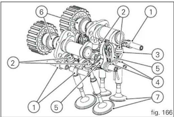

Performance data
Maximum speed in any gear should be reached only after the correct running-in period with the motorcycle properly serviced at the recommended intervals.

Important
Failure to follow these instructions will release Ducati
Motor Holding S.p.A. from any liability for any engine damage or shortened engine life.
Spark plugs
Make:
NGK
Type:
MAR9A-J
Fuel system
MITSUBISHI indirect electronic injection.
Oval throttle body (corresponding diameter): 56 mm
Injectors per cylinder: 1
Holes per injector: 12
Fuel supply: 95-98 RON.
Brakes
Separate-action anti-lock brake system operated by hall-type sensors mounted to each wheel, with phonic wheel detection: ABS can be disabled.
Front
Semi-floating drilled dual disc.
Braking material:
steel.
Carrier material:
aluminium.
Disc diameter:
320 mm.
Hydraulically operated by a control lever on handlebar right-hand side.
Brake calliper make:
BREMBO.
Type:
P4-32 pistons.
Friction material:
TT 2172
Master cylinder type:
PR18/19
Rear
Fixed drilled steel disc.
Disc diameter:
245 mm.
Hydraulically operated by pedal on right-hand side.
Make:
BREMBO
Type:
P34c pistons.
Friction material:
FERIT I/D 450 FF.
Master cylinder type:
PS 13c.

Warning
The brake fluid used in the brake system is corrosive.
In the event of accidental contact with eyes or skin, wash the affected area with abundant running water.


Transmission
Wet clutch controlled by the lever on left-hand side of the handlebar.
Transmission from engine to gearbox input shaft via spur gears.
Front chain sprocket/clutch gearwheel ratio:
33/61
6-speed gearbox with constant mesh gears, gear change pedal on left side of motorcycle.
Gearbox output sprocket/rear chain sprocket ratio:
15/40
Total gear ratios:
1 ^st gear 15/37
2^nd gear 17/30
3^rd gear 20/27
4^th gear 22/24
5^th gear 24/23
6^th gear 25/22
Drive chain from gearbox to rear wheel:
Make:
Regina
Type:
136ZRPB
Dimensions:
5/8"×1/16"
Links:
108

Important
The above gear ratios are approved and should not be modified under any circumstances.
However, if you wish to tune up your motorcycle for competitions or special tracks, Ducati Motor Holding S.p.A. will be pleased to provide information about the special ratios available. Please contact a Ducati Dealer or Authorised Service Centre.

Warning
If the rear sprocket needs replacing, contact a Ducati Dealer or authorised Service Centre. Incorrect replacement of this component could seriously compromise your safety and cause irreparable damage to the motorcycle.
Frame
ALS 420 steel tube trellis frame.
ALS 450 steel tube trellis frame rear subframe.
Die-cast light alloy connecting side plates, pivoted on the engine.
Steering head angle: 24° 30'
Wheels
Ten-spoke, light-alloy rims.
Front
Dimensions:
MT 3.50×17".
Rear
Dimensions:
MT 6.00×17".
Tyres
Front
Radial tubeless tyre.
Dimensions:
120/70-ZR17
Rear
Radial tubeless tyre.
Dimensions:
190/55-ZR17
Suspensions
Front
Hydraulic upside-down fork provided with external adjusters for rebound and compression damping and preload (for inner springs of fork legs).
Stanchion diameter:
50 mm, TIN-coated.
Rear wheel travel:
170 mm.
Rear
The shock absorber is adjustable for rebound and compression, with remote control for spring preload and is adjustable. Its upper section is pivot connected to the frame and the lower section is pivot connected to a light alloy single-sided swingarm. The swingarm hinges on a pivot shaft that passes through the frame and engine.
This system gives the motorcycle excellent stability.
Shock absorber stroke:
59.5 mm.
Rear wheel travel:
170 mm.

Note
In the "S" model, the front fork and the rear shock absorber are adjusted by electric impulses sent by the instrument panel to the adjusters.


Exhaust system
Equipped with catalytic converter in compliance with Euro 3 emission regulations.
One-piece stainless steel silencer with aluminium terminals. Catalytic converter built into the silencer and lambda sensors on the exhaust pipes at the head output.
Colour schemes
MTS1200 ABS
Ducati Anniversary red 473.101 (PPG); Clear lacquer part no. 228.880 (PPG); Racing Gray frame and black wheel rims.
Pearl white, code L2909004 (LECHLER); Enamel code L2920057 (LECHLER); Clear lacquer part no. 228.880 (PPG); Racing Gray frame and black wheel rims.
MTS1200 S ABS
Ducati Anniversary red 473.101 (PPG); Clear lacquer part no. 228.880 (PPG); Racing Gray frame and black wheel rims.
Pearl white, code L2909004 (LECHLER); Enamel code L2920057 (LECHLER); Clear lacquer code 228.880 (PPG); Racing Gray frame and black wheel rims. Black diamond code 57E22714 (AKZO);
Enamel code 54M22705 (AKZO); Clear lacquer code 228.880 (PPG); Racing Gray frame and black wheel rims.
Electric system
Basic electric items are:
Headlight:
low beam bulb type: 2 x H11 (12V-55W);
high beam bulb type: 2xH11 (12V-55W);
Parking light: led bulb (13.5V-4W).
Electrical controls on handlebars.
Turn signals:
Front: LED (9.8 V - 2.2 W);
Rear: halogen bulb type RY10W amber (12V-10W).
Horn.
Brake light switches.
Sealed battery, 12V-10 A.
GENERATOR 12V-500W.
ELECTRONIC RECTIFIER, protected by a 30A fuse located on the solenoid starter, behind the battery (2, fig. 169).
Starter motor: 12V-0.7 kW.
Tail light and brake signal:
led (13.5 V- 4.2 W/1.5 W)
Number plate light: bulb type C5W (12-5W).

Note
See "Replacing the high and low beam bulbs" on page
153 for relevant instructions.
Fuses
There are twelve fuses that protect the electric components located inside the front and rear fuse boxes, and one on the electric solenoid starter. There is a spare fuse in every box. Refer to the table below to identify the circuits protected by the various fuses and their ratings.
The front fuse box (A, fig. 153) is located inside the left panel and can be accessed by removing the inspection cover (2, fig. 167). To expose the fuses, lift the box protective cover. Mounting position and ampere capacity are marked on box cover.
FRONT FUSE BOX LEGEND (A, fig. 167)
| Pos. El. item Rating | |||
| 1 Lights 20 A | |||
| 2 Instrument panel 10 A | |||
| 3 | E | C | U |
| 4 Key-sense 15 A | |||
| 5 Injection solenoid 20 A | |||
| 6 Throttle opening starter motor solenoid (ETV) | 10 A | ||
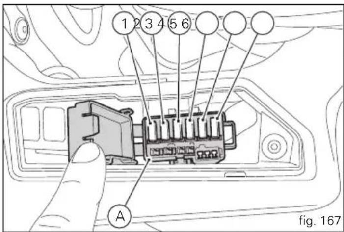
5
三
The rear fuse box (B, fig. 168) is located on the right frame on the rear sub-frame, to the side of the ABS control unit. To access the fuse box, remove the rider seat (see page 119). To expose the fuses, take off the box protective cover. Mounting position and ampere capacity are marked on box cover.
REAR FUSE BOX LEGEND (A, fig. 168)
Pos. El. item Rating
1 Black Box System (BBS) 7.5 A
2 Power outlets/navigator/10 A alarms
3 ABS 2 25 A
4 ABS 1 30 A
5 Fans 10 A
6 Diagnosis 7.5 A
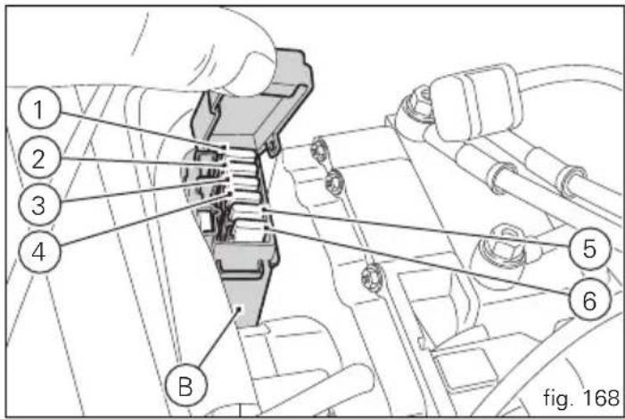
The main fuse (C, fig. 169), is positioned in front of the rear fuse box, on the solenoid starter (D). Remove the fuse cap (E) to reach it.
A blown fuse is identified by the interrupted centre link (F, fig. 170).

Important
To prevent short circuits, replace the fuse after the
Key-Off.

Warning
Never use a fuse with a rating other than specified.
Failure to observe this rule may damage the electric system or even cause fire.
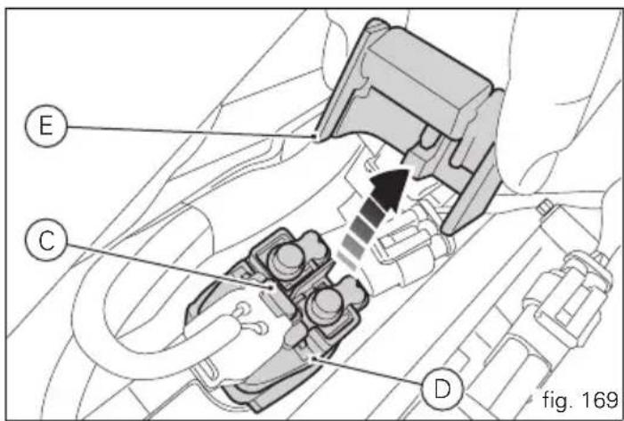

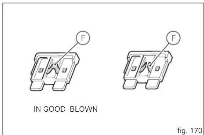
Injection/electrical system diagram legend 1200 ABS
1) Right-hand handlebar switch
2) Immobilizer
3) Hands Free relay
4) Hands free
5) Front fuse box
6) Right fan
7) Left fan
8) Fan relay
9) Fuel pump relay
10) Ride-by-wire relay (ETV)
11) Injection control unit (EMS)
12) Navigator
13) Left 12V power outlet
14) Right 12V power outlet
15) Rear fuse box
16) Data Acquisition/Diagnosis
17) Starter motor
18) ABS diagnosis
19) Fused solenoid
20) Battery
21) Wiring ground
22) Regulator
23) Generator
24) Fuel pump
25) Fuel level
26) Rear right turn signal
27) Rear light
28) Rear left turn signal
29) Rear wiring loom
30) Vehicle control unit (BBS)
Injection/electrical system diagram legend 1200 S ABS
1) Right-hand handlebar switch
2) Immobilizer
3) Hands Free relay
4) Hands free
5) Front fuse box
6) Right fan
7) Left fan
8) Fan relay
9) Fuel pump relay
10) Ride-by-wire relay (ETV)
11) Injection control unit (EMS)
12) Navigator
13) Left 12V power outlet
14) Right 12V power outlet
15) Rear fuse box
16) Data Acquisition/Diagnosis
17) Starter motor
18) ABS diagnosis
19) Fused solenoid
20) Battery
21) Wiring ground
22) Regulator
23) Generator
24) Fuel pump
25) Fuel level
26) Rear right turn signal
27) Rear light
28) Rear left turn signal
29) Rear wiring loom
30) Vehicle control unit (BBS)
31) Antitheft alarm
32) Exhaust valve starter motor
33) Gear sensor
61) Low beam headlight relay
62) Left low beam headlight
63) Left high beam headlight
64) Right high beam headlight
65) Right low beam headlight
66) High beam relay
67) Parking light
68) Rear suspension - compression - stepper C
69) Rear suspension - rebound - stepper D
70) Rear suspension - hydraulic spring preload
71) Active suspension ECU
72) Front fork - rebound - stepper B
73) Front fork - compression - stepper A
74) Heated handgrip connector

Wire colour coding
B Blue
W White
V Violet
BK Black
Y Yellow
R Red
LB Light blue
GR Grey
G Green
BN Brown
O Orange
P Pink

Note
The electrical system wiring diagram is at the end of
this manual.
Scheduled maintenance reminder
E
| km DUCATI SERVICE MILEAGE DATE |
| 1000 |
| 12000 |
| 24000 |
| 36000 |
| 48000 |
| 60000 |
For United States of America version Only
Reporting of safety defects
If you believe that your vehicle has a defect which could cause a crash or could cause injury or death, you should immediately inform the National Highway Traffic Safety Administration (NHTSA) in addition to notifying Ducati North America. If NHTSA receives similar complaints, it may open an investigation, and if it finds that a safety defect exists in a group of vehicles, it may order a recall and remedy campaign. However, NHTSA cannot become involved in individual problems between you, your dealer, or Ducati North America. To contact NHTSA, you may either call the Auto Safety Hotline toll-free at 1-800-424-9393 (or 366-0123 in Washington, D.C. area) or write to: NHTSA, 1200 New Jersey Avenue SE W43-488, Washington, D.C. 20590. You can also obtain other information about motor vehicle safety from the Hotline.
Safety warnings
Traffic Rules vary from jurisdiction to jurisdiction. Know the regulations in your jurisdiction before riding this motorcycle.

Warning
This motorcycle is designed and intended for use on streets and other smooth, paved areas only. Do not use this motorcycle on unpaved surfaces. Such use could lead to upset or other accident.
Noise emission warranty
Ducati Motor S.p.A. warrants that this exhaust system, at the time of sale, meets all applicable U.S. EPA Federal noise standards. This warranty extends to the first person who buys this exhaust system for purposes other than resale, and to all subsequent buyers. Warranty claims should be directed to: Ducati North America,
10443 Bandley Drive, Cupertino, California, 95014
Tel: 001.408.253.0499 - Fax: 001.408.253.4099.
Noise and exhaust emission control system information
Source of Emissions
The combustion process produces carbon monoxide and hydrocarbons. Control of hydrocarbons is very important because under certain conditions, they react to form photochemical smog when subjected to sunlight.
Carbon monoxide does not react in the same way, but is toxic. Ducati utilizes lean carburetor settings and other systems to reduce carbon monoxide and hydrocarbons.
Exhaust Emission Control System
The Exhaust Emission Control System is composed of lean carburetor settings, and no adjustments should be made except idle speed adjustments with the throttle stop screw. The Exhaust Emission Control System is separate from the crankcase emission control system.
Crankcase Emission Control System
The engine is equipped with a closed crankcase system to prevent discharging crankcase emissions into the atmosphere. Blow-by gas is returned to the combustion chamber through the air cleaner and the throttle body. Evaporative Emission Control System
California motorcycles are equipped with an evaporative emission control system which consists of a charcoal canister and associated piping. This system prevents the escape of fuel vapors from the throttle body and fuel tank.
Tampering warning
Tampering with Noise Control System Prohibited. Federal Law prohibits the following acts or causing thereof: (1) the removal or rendering inoperative by any person, other than for purposes of maintenance, repair, or replacement, of any device or element of design incorporated into any new vehicle for the purpose of noise control prior to its sale or delivery to the ultimate purchaser or while it is in use; or
(2) the use of the vehicle after such device or element of design has been removed or rendered inoperative by any person.
Among those acts presumed to constitute tampering are the acts listed below:
(1) Removal of, or puncturing the muffler, baffles, header pipes or any other component which conducts exhaust gases.
(2) Removal or puncturing of any part of the intake system.
(3) Lack of proper maintenance.
(4) Replacing any moving part of the vehicle, or parts of the exhaust or intake system, with parts other than those specified by the manufacturer.
This product should be checked for repair or replacement if the motorcycle noise has increased significantly through use. Otherwise, the owner may become subject to penalties under state and local ordinances.
Problems that may affect motorcycle emissions
If you are aware of any of the following symptoms, have the vehicle inspected and repaired by your local Ducati dealer.
Symptoms:
Hard starting or stalling after starting.
Rough idle.
Misfiring or backfiring during acceleration.
After-burning (backfiring).
Poor performance (driveability) and poor economy.
Riding safety
The points given below are applicable for every day motorcycle use and should be carefully observed for safe and effective vehicle operation.
A motorcycle does not provide the impact protection of an automobile, so defensive riding in addition to wearing protective apparel is extremely important.
Do not let protective apparel give you a false sense of security.
Before changing lanes, look over your shoulder to make sure the way is clear. Do not rely solely on the rear view mirror; you may misjudge a vehicle's distance and speed, or you may not see it at all.
When going up steep slopes, shift to a lower gear so that there is plenty of power to spare rather than overloading the engine.
When applying the brakes, use both the front and rear brakes. Applying only one brake for sudden braking may cause the motorcycle to skid and lose control.
When going down long slopes, control vehicle speed by closing the throttle. Use the front and rear brakes for auxiliary braking.
Riding at the proper rate of speed and avoiding unnecessarily fast acceleration are important not only for safety and low fuel consumption but also for long vehicle life and quieter operation.
When riding in wet conditions or on loose roadway surfaces, the ability to maneuver will be reduced. All of your actions should be smooth under these conditions. Sudden acceleration, braking or turning may cause loss of control.
When the roadway is wet, rely more on the throttle to control vehicle speed and less on the front and rear brakes.
The throttle should also be used judiciously to avoid skidding the rear wheel from too rapid acceleration or deceleration.
On rough roads, exercise caution, slow down, and grip the fuel tank with your knees for better stability.
When quick acceleration is necessary as in passing, shift to a lower gear to obtain the necessary power.
Do not down shift at too high an r.p.m. to avoid damage to the engine from overreving.
Avoiding unnecessary weaving is important to the safety of both the rider and other motorists.
Do not exceed the legal speed limit or drive too fast for existing conditions. High speed increases the influence of any condition affecting stability and the loss of control.
Operate motorcycle only at moderate speed and out of traffic until you have become thoroughly familiar with its operation and handling characteristics under all conditions. This is a very high performance motorcycle, designed and intended for use by experienced careful riders only!
A new motorcycle must be operated according to a special break-in procedure (see Running in recommendations).

Warning
Before starting engine, check for proper operation of
brake, clutch, shifter, throttle controls, correct fuel and oil supply.
Gasoline is extremely flammable and is explosive under certain conditions. Refuell in a well ventilated area with the engine stopped. Do not smoke or allow open flames or sparks when refuelling or servicing the fuel system.
Always close the fuel petcock when the engine is not running to prevent flooding of the throttle body. Do not overfill fuel tank (see instructions page 55).
Motorcycle exhaust contains poisonous carbon monoxide gas. Do not inhale exhaust gases and never run the engine in a closed garage or confined area.
Use only Ducati approved parts and accessories.
This motorcycle was not intended to be equipped with a sidecar or to be used to tow any trailer or other vehicle.
Ducati does not manufacture sidecars or trailers and cannot predict the effects of such accessories on handling or stability, but can only warn that the effects will be adverse and any damage to motorcycle components caused by the use of such accessories will not be remedied under warranty.
Warning Do not ride
Do not ride the motorcycle with helmets attached to the hook; the helmets could cause an accident by distracting the operator or interfering with normal vehicle operation.
Protective apparel
Always wear a helmet. Most motorcycle accident fatalities are due to head injuries.
For safety eye protection, gloves, and high top, sturdy boots should also be worn.
The exhaust system becomes very hot during operation, never touch the exhaust system. Wear clothing that fully covers your legs. Do not wear loose clothing which could catch on the control levers, footrests, wheels, or chain.
Any amount of alcohol will significantly interfere with your ability to safely operate your motorcycle. Don't drink and ride.
Vehicle identification number (VIN);
Every Ducati motorcycle is identified by two identification numbers (see page 9). fig. A specifically shows the frame identification numbers.
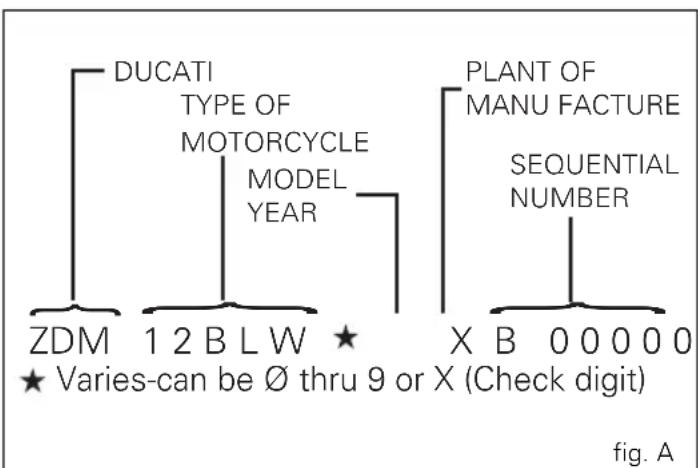
flowchart
graph TD
    A["DUCATI TYPE OF MOTORCYCLE MODEL YEAR"] --> B["ZDM 1 2 BLW ★"]
    C["PLANT OF MANU FACTURE SEQUENTIAL NUMBER"] --> D["X B 0 0 0 0 0 ★ Varies-can be ∅ thru 9 or X (Check digit)"]
Label location (fig. B)
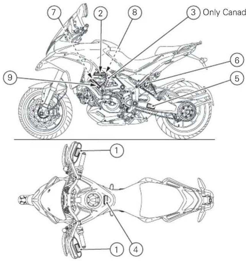
Only CanadaRight side Right side
fig. B
1
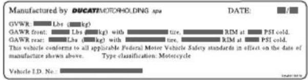
2
3 (Only Canada)
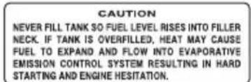
4
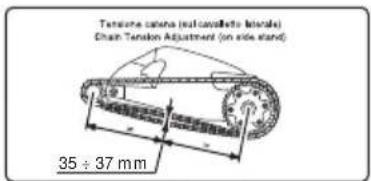
5
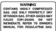
6
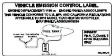
7
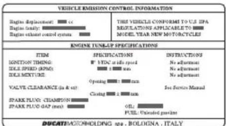
8
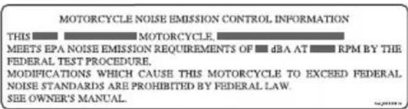
9
California emission control warranty statement Your warranty rights and obligations
The California Air Resources Board is pleased to explain the emission control system warranty on your MY 2010 motorcycle. In California, new motor vehicles must be designated, built and equipped to meet the State's stringent anti-smog standards. Ducati North America, Inc. must warrant the emission control system on your motorcycle for the periods of time listed below provided there has been no abuse, neglect or improper maintenance of your motorcycle. Your emission control system may include parts such as fuel-injection system, the ignition system, catalytic converter, and engine computer. Also included may be hoses, belts, connectors and other emission-related assemblies. Where a warrantable condition exists, Ducati North America, Inc. will repair your motorcycle at no cost to you including diagnosis, parts and labor.
Manufacturer's warranty coverage
- 5 years or 30,000 kilometers (18641 miles), whichever first occurs.
Owner's warranty responsibilities:
- As the motorcycle owner, you are responsible for the performance of the required maintenance listed in your owner's manual. Ducati North America, Inc. recommends that you retain all receipts covering maintenance on your motorcycle, but Ducati North America, Inc. cannot deny warranty solely for the lack of receipts or for your failure to ensure the performance of all scheduled maintenance.
- You are responsible for presenting your motorcycle to a Ducati dealer as soon as a problem exists. The warranty repairs should be completed in a reasonable amount of time, not to exceed 30 days.
- As the motorcycle owner, you should also be aware that Ducati North America, Inc. may deny you warranty coverage if your motorcycle or a part has failed due to abuse, neglect, improper maintenance or unapproved modifications.
If you have any questions regarding your warranty rights and responsibilities, you should contact Ducati North America, Inc. at 1 -408-253-0499 or the California Air Resource Board at 9528 Telstar Avenue, El Monte, CA 91731.
California evaporation emission system
This system consists of (fig. C):
1) Warn air inlet;
2) Canister;
3) Dell'Orto jet;
4) Fuel tank;
5) Breather pipe;
6) Intake manifolds.

Important
In the event of fuel system malfunction, contact
Ducati's authorized Service Centres.
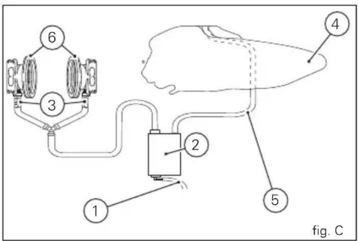
Ducati limited warranty on emission control system
Ducati North America, Inc., 10443 Bandley Drive Cupertino, California, 95014 warrants that each new 1998 and later Ducati motorcycle, that includes as standard equipment a headlight, tail-light and stoplight, and is street legal:
A) is designed, built and equipped so as to conform at the time of initial retail purchase with all applicable regulations of the United States Environmental Protection Agency, and the California Air Resources Board; and
B) is free from defects in material and workmanship which cause such motorcycle to fail to conform with applicable regulations of the United States Environmental Protection Agency or the California Air Resources Board for a period of use of 30,000 kilometers (18,641 miles) or 5 (five) years from the date of initial retail delivery, whichever first occurs.
I. Coverage
Warranty defects shall be remedied during customary business hours at any authorized Ducati motorcycle dealer located within the United States of America in compliance with the Clean Air Act and applicable regulations of the United States Environmental Protection Agency and the California Air Resources Board. Any part or parts replaced under this warranty shall become the property of Ducati.
In the state of California only, emissions related warranted parts are specifically defined by that state's Emissions Warranty Parts List. These warranted parts are: carburetor and internal parts; intake manifold; fuel tank, fuel injection system; spark advance mechanism; crankcase breather; air cutoff valves; fuel tank cap for evaporative emission controlled vehicles; oil filler cap; pressure control valve; fuel/vapor separator; canister; igniters; breaker governors; ignition coils; ignition wires; ignition points, condensers, and spark plugs if failure occurs prior to the first scheduled replacement, and hoses, clamps, fittings and tubing used directly in these parts. Since emission related parts may vary from model to model, certain models may not contain all of these parts and certain models may contain functionally equivalent parts.
In the state of California only, Emission Control System emergency repairs, as provided for in the California Administrative Code, may be performed by other than an authorized Ducati dealer. An emergency situation occurs when an authorized Ducati dealer is not reasonably available, a part is not available within 30 days, or a repair is not complete within 30 days. Any replacement part can be used in an emergency repair. Ducati will reimburse the owner for the expenses, including diagnosis, not to exceed Ducati's suggested retail price for all warranted parts replaced and labor charges based on Ducati's recommended time allowance for the warranty repair and the geographically appropriate hourly labor rate. The owner may be required to keep receipts and failed parts in order to receive compensation.
II. Limitations
This Emission Control System Warranty shall not cover any of the following:
A. Repair or replacement required as a result of
(1) accident,
(2) misuse,
(3) repairs improperly performed or replacements improperly installed,
(4) use of replacement parts or accessories not conforming to Ducati specifications which adversely affect performance and/or
(5) use in competitive racing or related events.
B. Inspections, replacement of parts and other services and adjustments required for routine maintenance.
C. Any motorcycle on which odometer mileage has been changed so that actual mileage cannot be readily determined.
III. Limited liability
A. The liability of Ducati under this Emission Control Systems Warranty is limited solely to the remedying of defects in material or workmanship by an authorized Ducati motorcycle dealer at its place of business during customary business hours. This warranty does not cover inconvenience or loss of use of the motorcycle or transportation of the motorcycle to or from the Ducati dealer. Ducati shall not be liable for any other expenses, loss or damage, whether direct, incidental, consequential or exemplary arising in connection with the sale or use of or inability to use the Ducati motorcycle for any purpose. Some states do not allow the exclusion or limitation
of any incidental or consequential damages, so the above limitations may not apply to you.
B. No express emission control system warranty is given by Ducati except as specifically set forth herein. Any emission control system warranty implied by law, including any warranty of merchantability or fitness for a particular purpose, is limited to the express emission control systems warranty terms stated in this warranty. The foregoing statements of warranty are exclusive and in lieu of all other remedies. Some states do not allow limitations on how long an implied warranty lasts so the above limitation may not apply to you.
C. No dealer is authorized to modify this Ducati Limited Emission Control Systems Warranty.
IV. Legal rights
This warranty gives you specific legal rights, and you may also have other rights which vary from state to state.
V. This warranty is in addition to the Ducati limited motorcycle warranty.
VI. Additional information
Any replacement part that is equivalent in performance and durability may be used in the performance of any maintenance or repairs. However, Ducati is not liable for these parts. The owner is responsible for the performance of all required maintenance. Such maintenance may be performed at a service establishment or by any individual. The warranty period begins on the date the motorcycle is delivered to an ultimate purchaser.
Ducati North America, Inc..
10443 Bandley Drive
Cupertino, California, 95014
Tel: 001.408.253.0499
Fax: 001.408.253.4099
E-mail: customerservice@ducatiusa.com
Web site: www.ducatiusa.com
Routine maintenance record
KM MI
DUCATI
SERVICE NAME
MILEAGE DATE
1,000 600
12,000 7,500
24,000 15,000
36,000 22,500
48,000 30,000
60,000 37,500
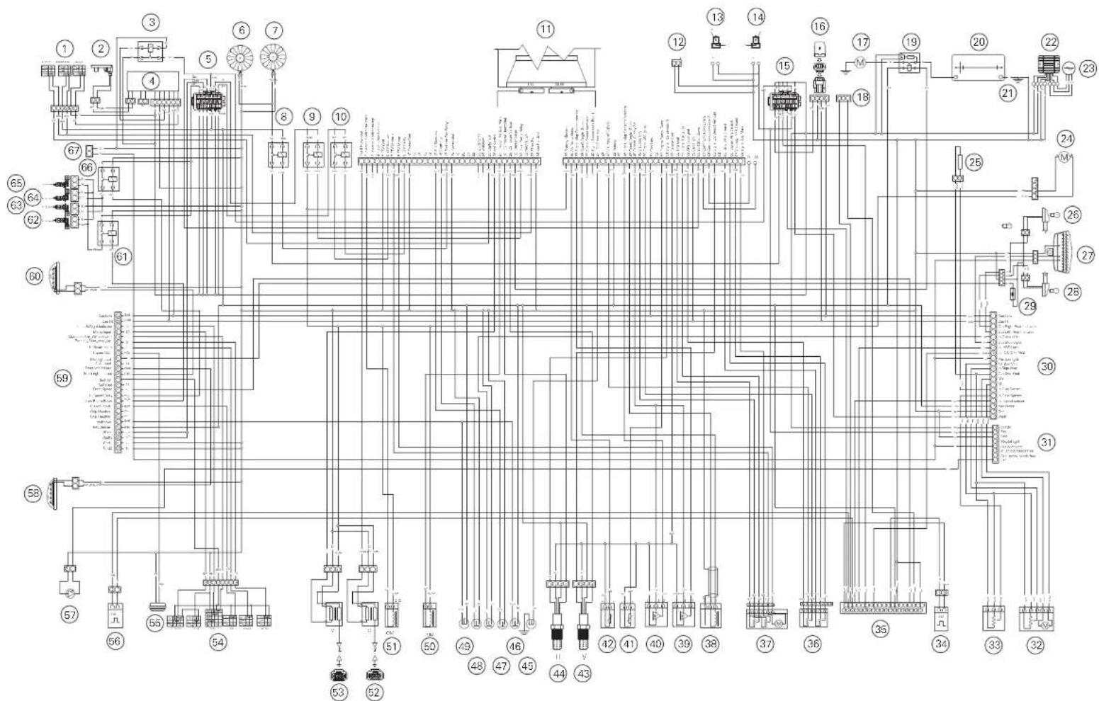
flowchart
graph TD
    A["1"] --> B["2"]
    B --> C["3"]
    C --> D["4"]
    D --> E["5"]
    E --> F["6"]
    F --> G["7"]
    G --> H["8"]
    H --> I["9"]
    I --> J["10"]
    J --> K["11"]
    K --> L["12"]
    L --> M["13"]
    M --> N["14"]
    N --> O["15"]
    O --> P["16"]
    P --> Q["17"]
    Q --> R["18"]
    R --> S["19"]
    S --> T["20"]
    T --> U["21"]
    U --> V["22"]
    V --> W["23"]
    W --> X["24"]
    X --> Y["25"]
    Y --> Z["26"]
    Z --> AA["27"]
    AA --> AB["28"]
    AB --> AC["29"]
    AC --> AD["30"]
    AD --> AE["31"]
    AE --> AF["32"]
    AF --> AG["33"]
    AG --> AH["34"]
    AH --> AI["35"]
    AI --> AJ["36"]
    AJ --> AK["37"]
    AK --> AL["38"]
    AL --> AM["39"]
    AM --> AN["40"]
    AN --> AO["41"]
    AO --> AP["42"]
    AP --> AQ["43"]
    AQ --> AR["44"]
    AR --> AS["45"]
    AS --> AT["46"]
    AT --> AU["47"]
    AU --> AV["48"]
    AV --> AW["49"]
    AW --> AX["50"]
    AX --> AY["51"]
    AY --> AZ["52"]
    AZ --> BA["53"]
    BA --> BB["54"]
    BB --> BC["55"]
    BC --> BD["56"]
    BD --> BE["57"]
    BE --> BF["58"]
    BF --> BG["59"]
    BG --> BH["60"]
    BH --> BI["61"]
    BI --> BJ["62"]
    BJ --> BK["63"]
    BK --> BL["64"]
    BL --> BM["65"]
MTS 1200 ABS
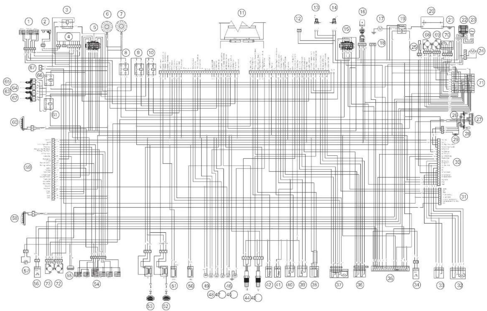
MTS 1200 S ABS
bar
| Category | Value | | :--- | :--- | | Stampato 04/2010 | 0 | | Cod. 913.7.170.1B | 0 |Ducati Motor Holding spa
www.ducati.com
Via Cavalieri Ducati, 3
40132 Bologna, Italia
Tel. +39 051 6413111
Fax +39 051 406580
cod 913.7.170.1B
- Note
- Warning
- Table of contents
- General Indications 8
- Instrument panel (Dashboard) 11
- Controls 99
- Main components and devices 117
- Directions for use 129
- Main maintenance operations 144
- General Indications
- Warranty
- Symbols
- Important
- Useful information for safe riding
- Carrying the maximum load allowed
- Information on load capacity
- Identification data
- Instrument panel (Dashboard)
- Instrument panel
- LCD unit functions
- LCD - Parameter setting/display
- Vehicle speed indicator
- Engine rpm indicator (RPM)
- Engaged gear indicator
- Fuel level indicator
- Coolant temperature
- Total distance covered indicator: "Odometer"
- "Trip 1" meter
- "Trip 2" meter
- Indication if the DTC function is active/not active
- Indication if the LAP function is active/not active
- Warning indication (Alarms/Signals)
- "Low" battery level
- Traction Control (DTC) deactivated
- Hands Free key (HF) not recognised
- "Low" Hands Free key (HF) battery level
- "High" engine coolant temperature
- Steering release error - Steering still locked
- Instrument panel diagnosis
- Maintenance indicator
- Residual range indication when the SERVICE is due
- Indication of range reached for SERVICE
- SET UP - "Riding Style set" indication
- "RANGE" indicator - remaining range
- Indicator "CONS I." - Instantaneous fuel consumption
- Indicator "CONS M." - Average fuel consumption
- Indicator "AVG" - Average speed
- Air temperature indicator
- Indicator "TIME TRIP" - Trip time
- "Riding Style" function (riding style change)
- "LOAD" FUNCTION (setup change)
- "Setting" menu
- ABS disabling function
- Battery voltage indicator (BATTERY)
- "Riding Style" customisation
- DTC (Ducati Traction Control) setting function
- Tips on how to select the sensitivity level
- Tips for use on the track
- Tips for use on the road
- E
- ENGINE setting function (Engine Power Control)
- DES setting function (Ducati Electronic Suspension)
- "FRONT" adjustment
- "REAR" adjustment
- "PRE-LOAD" adjustment
- DEFAULT function (Resetting Ducati default parameters)
- Instrument panel backlighting adjustment function
- LAP Activation/Deactivation function (lap time)
- LAP registration function
- Stored LAP display function
- DTC (Ducati Traction Control) on/off function
- Digital RPM indication function
- Clock setting function
- Clock setting
- The immobilizer system
- Keys (fig. 59)
- Duplicate keys
- Immobilizer override procedure
- PIN CODE activation function
- PIN CODE change function
- Light control
- Headlight control
- Turn signals (automatic reset)
- "Parking" function
- "Steering in position for being locked" indication
- "Steering lock" on indication
- Controls
- Position of motorcycle controls (fig. 74)
- "Hands free" system
- Hands free system Key-On and Key-Off
- Key-On/Key-Off using the red key on the handlebar with the active key
- Key-On/Key-Off using the key on the Hands free lock with the active key
- Key-On/Key-Off using the red key on the handlebar with the passive key
- Key-On/Key-Off using the key on the Hands free lock with the passive key
- Entering PIN CODE function for vehicle release
- LH switch (fig. 74)
- Clutch lever (fig. 92)
- RH switch (fig. 93)
- Throttle twistgrip (fig. 95)
- Front brake lever (fig. 96)
- Rear brake pedal (fig. 97)
- Gear change pedal (fig. 98)
- Adjusting the position of the gearchange and rear brake pedals
- Gear change pedal (fig. 99)
- Rear brake pedal (fig. 100)
- Main components and devices
- Position on the vehicle (fig. 101)
- Tank filler plug
- Opening
- Closing
- Electric fuel cap opening (optional)
- Seat lock
- Removal of the seats
- Refitting
- Side stand (fig. 109)
- Power outlet
- Adjusting the front fork
- Adjusting the rear shock absorber
- Motorcycle setup variation ("S" version only)
- Directions for use
- Running-in recommendations
- Maximum rpm (fig. 120)
- Up to 1000 km
- From 1000 to 2500 km
- Pre-ride checks
- KEY-OPERATED LOCKS
- ABS light
- ABS device
- Engine on/off
- Moving off
- Braking
- ABS system
- Stopping the motorcycle
- Parking
- Refuelling (fig. 132)
- Tool kit and accessories (fig. 133)
- Front semi-mudguard kit (fig. 134)
- Long rear mudguard kit
- Main maintenance operations
- Checking and topping up coolant level
- Checking brake and clutch fluid level
- Brake system
- Clutch system
- Checking brake pads for wear
- Lubricating cables and joints
- Adjusting throttle control free play
- Charging the battery (fig. 148)
- Checking drive chain tension (fig. 149)
- Chain lubrication
- Replacing the high and low beam bulbs
- Headlight
- Rear turn signals (fig. 157)
- Number plate light (fig. 158)
- Beam setting (fig. 159)
- Rear-view mirror adjustment (fig. 161)
- Tubeless tyres
- Tyre repair or change (Tubeless tyres)
- Minimum tread depth
- Checking engine oil level (fig. 163)
- Viscosity
- Cleaning and replacing the spark plugs (fig. 164)
- General cleaning
- Storing the bike away
- Important notes
- Scheduled maintenance chart
- Operations to be carried out by the customer
- Technical data
- Weights
- Warning Failure to ob
- Engine
- Timing system
- Desmodromic timing system (fig. 166)
- Performance data
- Spark plugs
- Fuel system
- Brakes
- Front
- Rear
- Transmission
- Frame
- Wheels
- Tyres
- Suspensions
- Exhaust system
- Colour schemes
- MTS1200 ABS
- MTS1200 S ABS
- Electric system
- Fuses
- Injection/electrical system diagram legend 1200 ABS
- Injection/electrical system diagram legend 1200 S ABS
- Wire colour coding
- Scheduled maintenance reminder
- For United States of America version Only
- Reporting of safety defects
- Safety warnings
- Noise emission warranty
- Noise and exhaust emission control system information
- Source of Emissions
- Exhaust Emission Control System
- Crankcase Emission Control System
- Tampering warning
- Among those acts presumed to constitute tampering are the acts listed below:
- Problems that may affect motorcycle emissions
- Riding safety
- Warning Do not ride
- Protective apparel
- Vehicle identification number (VIN);
- California emission control warranty statement Your warranty rights and obligations
- Manufacturer's warranty coverage
- Owner's warranty responsibilities:
- California evaporation emission system
- Ducati limited warranty on emission control system
- Coverage
- Limitations
- Limited liability
- Legal rights
- Additional information
- Routine maintenance record
Brand : DUCATI
Model : Multistrada 1200S ABS
Category : Motorcycle