
BT7504 - Flat screen mount B-Tech - Free user manual and instructions
Find the device manual for free BT7504 B-Tech in PDF.


| Product Type | Flat Screen Mount |
| Brand | B-Tech |
| Model | BT7504 |
| Compatible Screen Sizes | 32" - 65" |
| VESA Patterns | 200x200 mm to 600x400 mm |
| Weight Capacity | 50 kg (110 lbs) |
| Material | High-grade steel |
| Finish | Powder-coated black |
| Tilt Adjustment | -5° to +15° |
| Swivel Adjustment | Fixed (no swivel) |
| Profile Distance from Wall | 25 mm |
| Wall Plate Dimensions | 500 x 200 mm |
| Included Accessories | Mounting hardware, bubble level, user manual |
| Recommended Wall Type | Solid concrete, brick, or wood studs |
| Safety Compliance | UL certified |
| Maintenance & Cleaning | Wipe with a dry, soft cloth; avoid solvents |
| Spare Parts & Repairability | Contact B-Tech support for replacements; limited repairability |
| Warranty | 10 years (subject to terms) |
Frequently Asked Questions - BT7504 B-Tech
User questions about BT7504 B-Tech
0 question about this device. Answer the ones you know or ask your own.
Ask a new question about this device
Download the instructions for your Flat screen mount in PDF format for free! Find your manual BT7504 - B-Tech and take your electronic device back in hand. On this page are published all the documents necessary for the use of your device. BT7504 by B-Tech.
USER MANUAL BT7504 B-Tech
This Pack Contains 1 Trolley / Stand
PLEASE KEEP THIS FOR FUTURE REFERENCE

natural_image
Modern display stand with a cityscape background and metallic frame (no text or symbols visible)FEATURES
- Designed for flat screens up to 42" (107cm) / 24kg (53lbs)
- Fits VESA mounting patterns:
75 x 75mm, 100 x 100mm,
200 x 100mm and 200 x 200mm
• Non-marking 50mm braked castors included
• Supplied with optional levelling feet - ∅60mm x 1100mm pole
- Trolley dimensions (including wheels): 1310mm (51.6") x 455mm (17.9") x 735mm (28.9")


CONTENTS
Installation Safety Notes....2
Parts List....4
Safety Instructions....6
Installation Instructions....7
Optional Accessories....17
Product Dimensions....18
B-Tech Contact Details....20
INSTALLATION TOOLS REQUIRED
Crosshead screwdriver

Hex Keys (Supplied)

B-TECH AUDIO VIDEO MOUNTS
www.btechavmounts.com
INSTALLATION SAFETY INSTRUCTIONS

CAUTION: This stand is intended for use
only with the maximum weights indicated. Use with flat screen heavier than the maximum indicated may result in instability causing possible injury.
Do not attempt to install this product until all instructions and warnings have been read and properly understood. Please keep these instructions for future reference.
B-Tech International Limited, its distributors and dealers are not liable or responsible for damage or injury caused by improper installation, improper use or failure to observe these safety instructions. In such cases, all guarantees will expire.
General
Great care must always be taken during installation as most AV equipment is of a fragile nature, possibly heavy and easily damaged if dropped.
If you do not fully understand the instructions or are not sure how to install this product safely, then please consult a professional for advice and/or to install this product for you. Failure to mount this product correctly may cause serious injury or death both during installation and at any time thereafter. Do not mount any AV equipment that exceeds the specific weight limit of the product you are installing. This weight limit will be clearly stated on each product and its packaging and will vary from product to product.
Product location
Please pay careful attention to where this product is located. Some locations are not suitable for installation.
If located in a public or frequently populated area ensure that the product is out of the immediate reach of people.
Fixing hardware
It is highly recommended that all fixing screws be used where supplied and that the purpose of all other fixing hardware is fully understood. In some cases more AV equipment fixing hardware will be supplied to accommodate different models of equipment and set up configurations.
The installer must be satisfied that any supplied fixing hardware is suitable for each specific installation. If any fixing screws or included hardware are deemed not sufficient for a safe installation then please consult a professional or your local hardware store.
Hazard limitation
When routing cables take advantage of any built in cable management features that the product might provide and ensure that all cables are tidy and secure. Check to see that any moving aspect of the product can do so unhindered by any cabling.
Some products have moving parts and the potential to cause injury through the crushing or trapping of fingers or other body parts.
Particular attention to the nature of moving parts is required especially when assembling installing and adjusting during set up.
Immediately after installations double-check that the work done is safe and secure. Double-check all necessary fixings are present and are of ample tightness.
It is recommended that periodic inspections of the product and its fixing points are made as frequently as possible to ensure that safety is maintained. If in doubt consult a professional AV installer or other suitably qualified person.
The articulating arm may spring upward and may cause injury or damage to the equipment when the monitor is removed. Secure the arm by lifting the arm to highest position, to remove monitor safely.
CS
Suitable for loads up to 24kg (53lbs)
natural_image
Technical line drawing of a mechanical bracket assembly (no text or symbols)
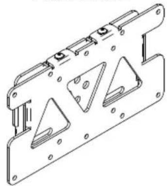
| REF | PART NAME QTY | |
| 1 | TROLLEY BASE 1 | |
| 2 | 1.1M POLE 1 | |
| 3 | MOUNTING PLATE 1 | |
| 4 | INTERFACE PLATE 1 | |
| 5 | WHEEL (FOR PART 1) 4 | |
| 6 | BASE END CAP 4 | |
| 7 | M16 x 60mm HEX BOLT 1 | |
| 8 | COLLAR 1 | |
| 9 | COLLAR COVER 2 | |
| 10 | POLE END CAP 1 | |
| 11 | M10 x 20mm HEX GRUB SCREW | 2 |
| 12 | M8 x 12mm HEX SCREW | 2 |
| 13 | M8 SPRING WASHER | |
| 14 | M4 x 10mm HEX SCREW | 2 |
| 15 | LEVELLING FOOT (FOR PART 1) | 4 |
| 16 | ADAPTOR ARM | 2 |
| 17 | M4 x 8mm PIN HEX SCREW | 4 |
| 18 | 2.5mm HEX KEY (FOR PARTS A, B & 14) | 1 |
| 19 | 2.5mm PIN HEX KEY (FOR PART 17) | 1 |
| 20 | 3mm PIN HEX KEY (FOR PARTS C & D) | 1 |
| 21 | 4mm PIN HEX KEY (FOR PARTS E & F) | 1 |
| 22 | 5mm HEX KEY (FOR PARTS 11 & 12) | 1 |
| 23 | 14mm HEX KEY (FOR PART 7) | 1 |
| 24 | 22mm SPANNER (FOR PART 5) 1 | |
| INTERFACE KIT | ||
| A | M4 x 10mm HEX SCREW | 6 |
| B | M4 x 15mm HEX SCREW | 6 |
| C | M5 x 16mm PIN HEX SCREW | 4 |
| D | M5 x 25mm PIN HEX SCREW | 4 |
| E | M6 x 16mm PIN HEX SCREW | 4 |
| F | M6 x 25mm PIN HEX SCREW | 4 |
| G | M4 METAL WASHER | 4 |
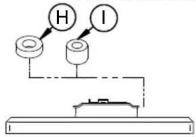
| H | M4 x 4mm SPACER (FOR PART B) | 6 |
| I | M6 x 12mm SPACER (FOR PARTS D & F) | 4 |
| J M8 | TO M4 ADAPTOR | 4 |

For fixed installation select the levelling feet. For mobile application select the braked wheels.
i. Screw the levelling feet to the trolley.

flowchart
graph TD
    A["Component 1"] --> B["Component 2"]
    B --> C["Component 3"]
    C --> D["Component 4"]
    D --> E["Component 5"]
    E --> F["Component 6"]
    F --> G["Component 7"]
    G --> H["Component 8"]
    H --> I["Component 9"]
    I --> J["Component 10"]
    J --> K["Component 11"]
    K --> L["Component 12"]
    L --> M["Component 13"]
    M --> N["Component 14"]
    N --> O["Component 15"]
    O --> P["Central Component"]
    style A fill:#f9f,stroke:#333
    style B fill:#ccf,stroke:#333
    style C fill:#cfc,stroke:#333
    style D fill:#fcc,stroke:#333
    style E fill:#cff,stroke:#333
    style F fill:#ffc,stroke:#333
    style G fill:#cfc,stroke:#333
    style H fill:#fcc,stroke:#333
    style I fill:#cfc,stroke:#333
    style J fill:#fcc,stroke:#333
    style K fill:#cfc,stroke:#333
    style L fill:#fcc,stroke:#333
    style M fill:#cfc,stroke:#333
    style N fill:#fcc,stroke:#333
    style O fill:#cfc,stroke:#333
    style P fill:#fcc,stroke:#333
    style Q fill:#cfc,stroke:#333
    style R fill:#fcc,stroke:#333
    style S fill:#cfc,stroke:#333
    style T fill:#fcc,stroke:#333
    style U fill:#cfc,stroke:#333
    style V fill:#fcc,stroke:#333
    style W fill:#cfc,stroke:#333
    style X fill:#fcc,stroke:#333
    style Y fill:#cfc,stroke:#333
    style Z fill:#fcc,stroke:#333
ii. Screw the wheels to the trolley.
LOCK WHEELS PRIOR TO
INSTALLATION

natural_image
Simple black-and-white icon of a male gender symbol with a curved arrow, no text or labels present.
2
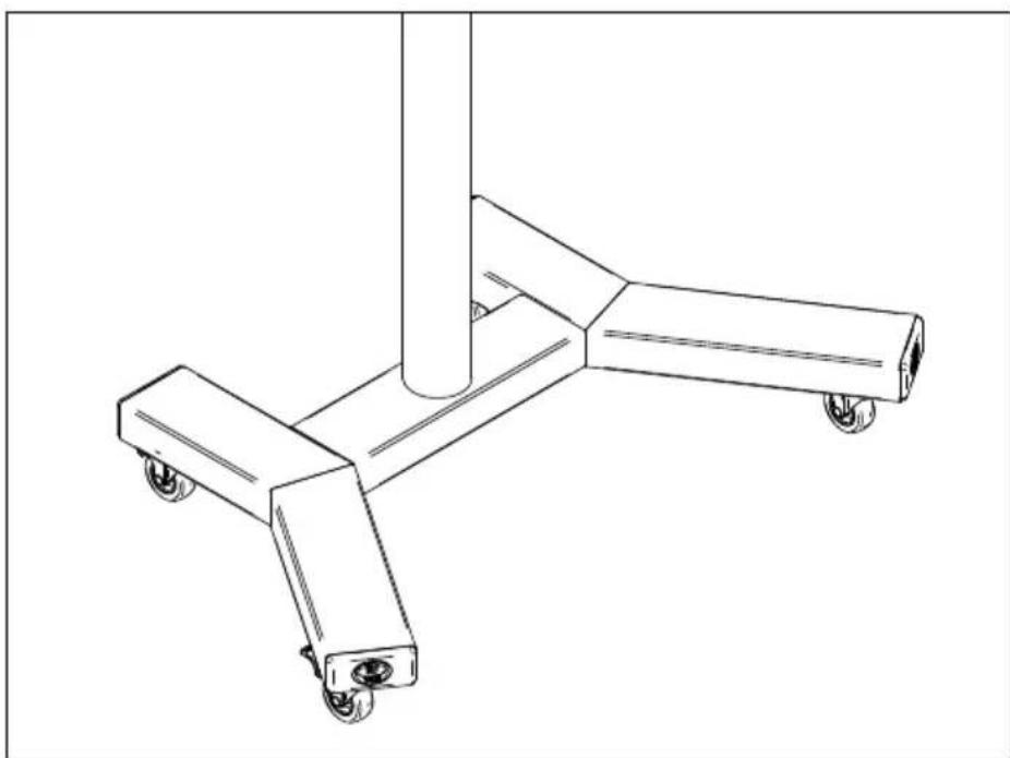
Attach the pole to the trolley base.

natural_image
Technical line drawing of a three-legged support structure with wheels and a vertical pole (no text or symbols)IF ATTACHING AV COMPONENT SHELF, DO SO NOW
3
Fix the collar to the mounting plate.


natural_image
Technical line drawing of a mechanical bracket with mounting holes and internal slots (no text or symbols)4
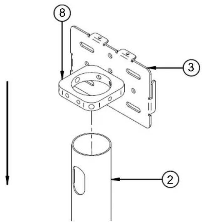
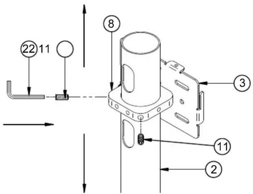
Fix collar and mounting plate to the pole.
i.Slide the collar and mounting plate onto the pole.
ii. Fix at desired height using parts 11.
| SCREEN WITH M8 FIXINGS | ||
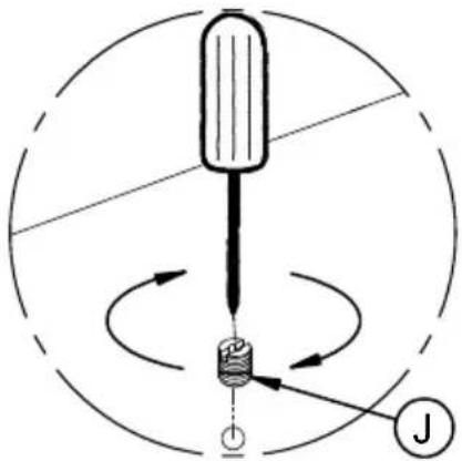 | Screw parts J into the flat screen fixing holes. Continue with screen mounting step 6. | 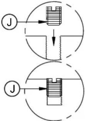 |
| 5 | There are two methods of attaching the mount to the screen, depending on the screen fixing pattern. | |
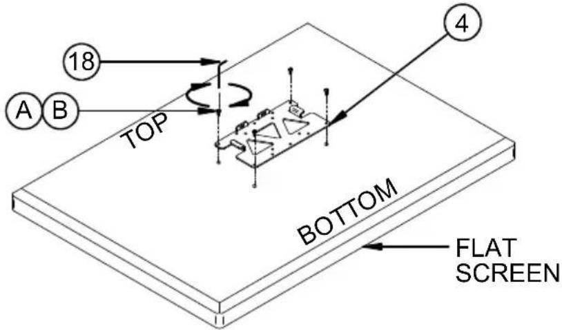
| A) VESA Fixings: 75 x 75mm, 100 x 100mm or 200 x 100mm (page 12) B) VESA Fixings: 200 x 200mm (page 13) | ||
| A | VESA Fixings: 75 x 75mm, 100 x 100mm, 200 x 100mm | |
| i. Attach interface plate to back of the screen. | ||
 | ||
| 12 | FOR SCREENS WITH RECESS FIXINGS   | |
B
VESA Fixing: 200 x 200mm
i. Fix the adaptor arms to the interface.

ii. Attach interface to back of the screen.

FOR SCREENS WITH RECESS FIXINGS
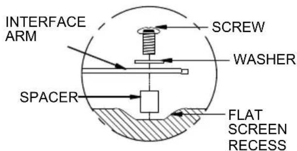
6
Attach flat screen to trolley.
i. Hook on flat screen
⚠ WARNING: Lock wheels before hooking flat screen on. ⚠
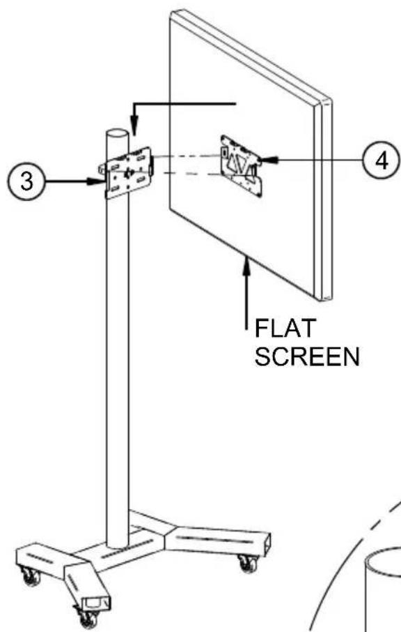

ii. Secure in place using parts 14.

7
Attach the collar covers (parts 9), pole end caps (parts 10) and base ends caps (parts 6) to trolley / stand.

OPTIONAL ACCESSORIES


BT7504 PRODUCT DIMENSIONS


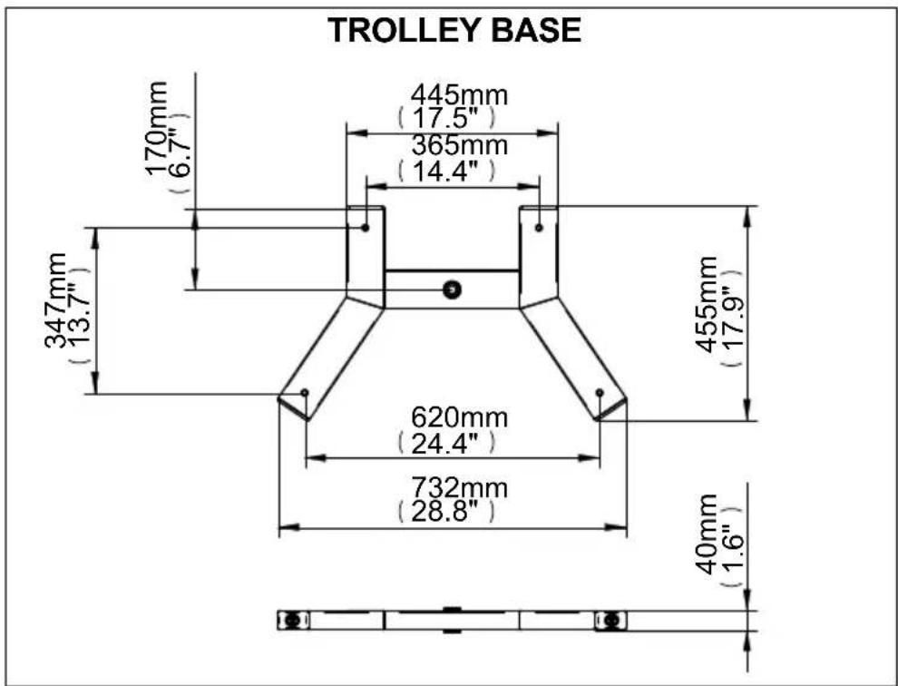
BT7504
PRODUCT DIMENSIONS
INTERFACE PLATE

INTERFACE WITH ADAPTORS

MOUNTING PLATE


BETTER BY DESIGN
www.btechavmounts.com
B-TECH AUDIO VIDEO MOUNTS
HEAD OFFICE
Bennett House, Long March, Daventry, Northants., NN11 4NR, UK
Email: info@btechavmounts.co.uk
EUROPE
BELGIUM
Brixtonlaan 32, Zaventem 1930,
Brussels, Belgium
Email: info@btechproav.com
GERMANY
Ruby Industrial Complex,
Singapore 347740
Email: info@btechavmounts.com.sg
ASIA PACIFIC
1503 Prosperity Millennia Plaza,
Quarry Bay, Hong Kong
Email: info@btechavmounts.com.hk
©2010 Bennett Technologies Limited. All rights reserved.
B-Tech Audio Video Mounts is a division of Bennett Technologies Limited.
B-Tech and Better By Design are registered trademarks of Bennett Technologies Limited.
All other brands and product names are trademarks of their respective owners.
Photographs are for illustrative purposes only. E&OE.
IP-BT7504-V1-PROBX-251010-1 MADE IN CHINA


- FEATURES
- CONTENTS
- INSTALLATION TOOLS REQUIRED
- INSTALLATION SAFETY INSTRUCTIONS
- CAUTION: This stand is intended for use
- General
- Product location
- Fixing hardware
- Hazard limitation
- CS
- IF ATTACHING AV COMPONENT SHELF, DO SO NOW
- B
- BT7504 PRODUCT DIMENSIONS
- BT7504
- PRODUCT DIMENSIONS
- B-TECH AUDIO VIDEO MOUNTS
- EUROPE
Brand : B-Tech
Model : BT7504
Category : Flat screen mount