
220Xi4 - Label printer ZEBRA - Free user manual and instructions
Find the device manual for free 220Xi4 ZEBRA in PDF.


| Product Type | Industrial Label Printer |
| Brand | Zebra |
| Model | 220Xi4 |
| Print Technology | Thermal Transfer / Direct Thermal |
| Print Resolution | 203 dpi (optional 300 dpi) |
| Max Print Width | 8.5 inches (216 mm) |
| Max Print Speed | 10 inches per second |
| Media Width | 0.79 to 8.5 inches (20 to 216 mm) |
| Media Length | 0.375 to 39 inches (9.5 to 991 mm) |
| Ribbon Width | 1.3 to 8.5 inches (33 to 216 mm) |
| Ribbon Length | 1476 feet (450 m) |
| Interface | Serial RS-232, Parallel, USB, Ethernet (optional) |
| Memory | 16 MB SDRAM, 8 MB Flash |
| Display | LCD with backlight |
| Dimensions (W x D x H) | 15.2 x 10.9 x 12.0 inches (386 x 277 x 305 mm) |
| Weight | 65 lbs (29.5 kg) |
| Power Supply | 100-240 V AC, 50/60 Hz |
| Operating Temperature | 41 to 104 °F (5 to 40 °C) |
| Storage Temperature | -40 to 140 °F (-40 to 60 °C) |
| Humidity | 20% to 85% non-condensing |
| Safety Certifications | UL, C-UL, CE, FCC Class A |
| Included Accessories | Power cord, quick start guide, ribbon take-up spindle |
Frequently Asked Questions - 220Xi4 ZEBRA
User questions about 220Xi4 ZEBRA
0 question about this device. Answer the ones you know or ask your own.
Ask a new question about this device
Download the instructions for your Label printer in PDF format for free! Find your manual 220Xi4 - ZEBRA and take your electronic device back in hand. On this page are published all the documents necessary for the use of your device. 220Xi4 by ZEBRA.
USER MANUAL 220Xi4 ZEBRA
natural_image
Abstract black and white geometric pattern with curved white lines on a dark background (no text or symbols)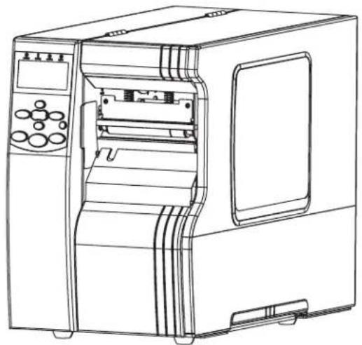
natural_image
Line drawing of a laboratory instrument with control panel and side panel (no text or symbols)Zebra®
Xi4™
User Guide
© 2009 ZIH Corp. The copyrights in this manual and the software and/or firmware in the printer described therein are owned by ZIH Corp. Unauthorized reproduction of this manual or the software and/or firmware in the printer may result in imprisonment of up to one year and fines of up to \$10,000 (17 U.S.C.506). Copyright violators may be subject to civil liability.
This product may contain ZPL ^® , ZPL II ^® , and ZebraLink ^™ programs; Element Energy Equalizer ^® Circuit; E ^3® ; and Monotype Imaging fonts. Software © ZIH Corp. All rights reserved worldwide.
ZebraLink and all product names and numbers are trademarks, and Zebra, the Zebra logo, ZPL, ZPL II, Element Energy Equalizer Circuit, and E^3 Circuit are registered trademarks of ZIH Corp. All rights reserved worldwide.
AS/400 is a registered trademark of International Business Machines Corporation in the United States, other countries, or both.
All other brand names, product names, or trademarks belong to their respective holders. For additional trademark information, please see “Trademarks” on the product CD.
Proprietary Statement This manual contains proprietary information of Zebra Corporation and its subsidiaries (“Zebra Technologies”). It is intended solely for the information and use of parties operating and maintaining the equipment described herein. Such proprietary information may not be used, reproduced, or disclosed to any other parties for any other purpose without the express, written permission of Zebra Technologies Corporation.
Product Improvements Continuous improvement of products is a policy of Zebra Technologies Corporation. All specifications and designs are subject to change without notice.
Liability Disclaimer Zebra Technologies Corporation takes steps to ensure that its published Engineering specifications and manuals are correct; however, errors do occur. Zebra Technologies Corporation reserves the right to correct any such errors and disclaims liability resulting therefrom.
Limitation of Liability In no event shall Zebra Technologies Corporation or anyone else involved in the creation, production, or delivery of the accompanying product (including hardware and software) be liable for any damages whatsoever (including, without limitation, consequential damages including loss of business profits, business interruption, or loss of business information) arising out of the use of, the results of use of, or inability to use such product, even if Zebra Technologies Corporation has been advised of the possibility of such damages. Some jurisdictions do not allow the exclusion or limitation of incidental or consequential damages, so the above limitation or exclusion may not apply to you.

Declaration of Conformity
We have determined that the Zebra printers identified as the
Xi4™ Series
110Xi4 ^TM , 140Xi4 ^TM , 170Xi4 ^TM , 220Xi4 ^TM
manufactured by:
Zebra Technologies Corporation
333 Corporate Woods Parkway
Vernon Hills, Illinois 60061-3109 U.S.A.
Have been shown to comply with the applicable technical standards of the FCC
For Home, Office, Commercial, and Industrial use
If no unauthorized change is made in the equipment, and if the equipment is properly maintained and operated.
Compliance Information
FCC Compliance Statement
This device complies with Part 15 rules. Operation is subject to the following two conditions:
- This device may not cause harmful interference, and
- This device must accept any interference received, including interference that may cause undesired operation.
The user is cautioned that any changes or modifications not expressly approved by Zebra Technologies could void the user's authority to operate the equipment. To ensure compliance, this printer must be used with Shielded Communication Cables.
Canadian DOC Compliance Statement
This Class B digital apparatus complies with Canadian ICES-003.
natural_image
Abstract black and white pattern with curved white and black shapes (no text or symbols)Declaration of Conformity 3
Compliance Information 4
About This Document 9
Who Should Use This Document 10
How This Document Is Organized 10
Contacts 11
Document Conventions.... 12
1 • Introduction ...... 15
Printer Components 16
Control Panel 17
2 • Printer Setup 19
Before You Begin 20
Handling the Printer 21
Unpack and Inspect the Printer 21
Store the Printer 21
Ship the Printer.... 21
Select a Site for the Printer.... 22
Select a Surface 22
Provide Proper Operating Conditions.... 22
Allow Proper Space 22
Provide a Data Source 22
Provide a Power Source.... 22
Select a Data Communication Interface 23
Data Cables and Wireless Cards 24
Connect the Printer to the Computer or Network 24
Connect the Printer to a Power Source 28
Power Cord Specifications 29
Install Control Panel Keypad Cover 30
Types of Media 31
Ribbon Overview.... 33
When to Use Ribbon.... 33
Coated Side of Ribbon 33
3 · Operations ...... 35
Print Modes and Printer Options.... 36
Print Mode Descriptions and Printer Requirements 36
Media Paths 37
Prepare the Media for Loading 39
Load Media in Tear-Off Mode 43
Load Media in Peel-Off Mode 47
Load Media in Cutter Mode. 54
Load Media in Rewind Mode 59
Remove Media Liner from the Rewind Spindle. 66
Load Ribbon 68
Remove Used Ribbon. 73
Calibrate the Printer 75
Adjust Transmissive Media Sensors.... 77
Upper Media Sensor....77
Lower Media Sensor....80
Adjust Printhead Pressure and Toggle Position 81
Toggle Position Adjustment 81
Printhead Pressure Adjustment 82
4 · Configuration 85
Setup Mode.... 86
Enter and Use Setup Mode 86
Exit Setup Mode 87
Change Password-Protected Parameters 88
Default Password Value 88
Disable the Password Protection Feature 88
Print a Configuration Label 89
Print a Network Configuration Label 90
Standard Control Panel Parameters 91
Additional Control Panel Parameters .....113
5 · Routine Maintenance .... 115
Replacing Printer Components....116
Ordering Replacement Parts 116
Recycling Printer Components....116
Lubrication 116
Cleaning Schedule and Procedures 117
Clean the Exterior....117
Clean the Media Compartment. 117
Clean the Printhead and Platen Roller 118
Clean the Sensors 121
Clean the Snap Plate 124
Clean the Cutter 125
Replace the Fuse 126
6 • Troubleshooting 129
Troubleshooting Checklists.... 130
LCD Error Messages 131
Print Quality Problems 137
Calibration Problems.... 141
Communications Problems.... 142
Ribbon Problems 143
Miscellaneous Printer Problems 144
Printer Diagnostics 146
Power-On Self Test.... 146
CANCEL Self Test 147
PAUSE Self Test.... 148
FEED Self Test 149
FEED and PAUSE Self Test 152
Communications Diagnostics Test 153
Sensor Profile 154
7 · Specifications 155
Features 156
Standard Features 156
Optional Features.... 156
Print Modes.... 156
Zebra Programming Language (ZPL).... 157
Bar Codes.... 157
General Specifications 158
Physical Specifications 158
Electrical Specifications 158
Environmental Conditions for Operation and Storage 158
Print Specifications by Model 159
110Xi4.... 159
140Xi4, 170Xi4, and 220Xi4 160
Ribbon Specifications 161
140Xi4, 170Xi4, and 220Xi4 161
Media Specifications....162
110Xi4.... 162
140Xi4, 170Xi4, and 220Xi4 Printers ..... 163
End User License Agreement 165
Glossary 171
Index 175
About This Document

natural_image
Abstract black and white pattern with curved white and black shapes (no text or symbols)This section provides you with contact information, document structure and organization, and additional reference documents.
Contents
Who Should Use This Document....10
How This Document Is Organized .... 10
Contacts....11
Document Conventions 12
Who Should Use This Document
This User Guide is intended for use by any person who needs to perform routine maintenance, upgrade, or troubleshoot problems with the printer.
How This Document Is Organized
The User Guide is set up as follows:
| Section Description | |
| Introduction on page 15 | This section provides a high-level overview of the printer and its components. |
| Printer Setup on page 19 | This section provides the tasks that you must complete and the issues that you must consider before you load and configure your printer. |
| Operations on page 35 | This section provides the procedures for loading and calibrating the printer. |
| Configuration on page 85 | This section describes the control panel parameters that are used to configure the printer for operation. |
| Routine Maintenance on page 115 | This section provides routine cleaning and maintenance procedures. |
| Troubleshooting on page 129 | This section provides information about errors that you might need to troubleshoot. Assorted diagnostic tests are included. |
| Specifications on page 155 | This section provides the features of and specifications for this printer. |
| Glossary on page 171 | The glossary provides a list of common terms. |
Contacts
Technical Support via the Internet is available 24 hours per day, 365 days per year.
Web Site: www.zebra.com
E-mail Back Technical Library:
E-mail address: emb@zebra.com
Subject line: Emaillist
Self Service Knowledge Base: www.zebra.com/knowledgebase
Online Case Registration: www.zebra.com/techrequest
| Which Department Do You Need? | The Americas | Europe, Africa, Middle East, India | Asia Pacific |
| Regional Headquarters | Zebra Technologies International, LLC333 Corporate Woods ParkwayVernon Hills, IL 60061-3109U.S.A.T: +1 847 793 2600Toll-free +1 800 423 0422F: +1 847 913 8766 | Zebra Technologies Europe LimitedDukes MeadowMillboard RoadBourne EndBuckinghamshire, SL8 5XFUnited KingdomT: +44 (0) 1628 556000F: +44 (0) 1628 556001 | Zebra Technologies AsiaPacific Pte. Ltd.120 Robinson Road#06-01 Parakou BuildingSingapore 068913T: +65 6858 0722F: +65 6885 0838 |
| Technical SupportFor questions on the operation of Zebra equipment and software, please call your distributor.For additional assistance, contact us.Please have your model and serial numbers available. | T: +1 877 ASK ZEBRA (275 9327)F: +1 847 913 2578Hardware: ts1@zebra.comSoftware: ts3@zebra.comKiosk printers:T: +1 866 322 5202E: kiosksupport@zebra.com | T: +44 (0) 1628 556039F: +44 (0) 1628 556003E: Tseurope@zebra.com | T: +65 6858 0722F: +65 6885 0838E: China: tschina@zebra.comAll other areas:tsasiapacific@zebra.com |
| Repair Service DepartmentFor back-to-base service and repair. | T: +1 877 ASK ZEBRA (275 9327)F: +1 847 821 1797E: repair@zebra.comTo request a repair in the U.S., go to www.zebra.com/repair | T: +44 (0) 1772 693069F: +44 (0) 1772 693046New requests: ukrma@zebra.comStatus updates:repairupdate@zebra.com | T: +65 6858 0722F: +65 6885 0838E: China: tschina@zebra.comAll other areas:tsasiapacific@zebra.com |
| Technical Training DepartmentFor Zebra product training courses. | T: +1 847 793 6868T: +1 847 793 6864F: +1 847 913 2578E: ttamerica@zebra.com | T: +44 (0) 1628 556000F: +44 (0) 1628 556001E: Eurtraining@zebra.com | T: +65 6858 0722F: +65 6885 0838E: China: tschina@zebra.comAll other areas:tsasiapacific@zebra.com |
| Inquiry DepartmentFor product literature and distributor and dealer information. | T: +1 877 ASK ZEBRA (275 9327)E: inquiry4@zebra.com | T: +44 (0) 1628 556037F: +44 (0) 1628 556005E: mseurope@zebra.com | E: China: GCmarketing@zebra.comAll other areas:APACChannelmarketing@zebra.com |
| Customer Service Department (US)Internal Sales Department (UK)For printers, parts, media, and ribbon, please call your distributor or contact us. | T: +1 877 ASK ZEBRA (275 9327)E: clientcare@zebra.com | T: +44 (0) 1628 556032F: +44 (0) 1628 556001E: cseurope@zebra.com | T: +65 6858 0722F: +65 6885 0836E: China: order-csr@zebra.comAll other areas:csasiapacific@zebra.com |
| Key:T: TelephoneF: FacsimileE: E-mail | |||
Document Conventions
The following conventions are used throughout this document to convey certain information.
Alternate Color (online only) Cross-references contain hot links to other sections in this guide. If you are viewing this guide online in .pdf format, you can click the cross-reference (blue text) to jump directly to its location.
LCD Display Examples Text from a printer's Liquid Crystal Display (LCD) appears in Bubbledot ICG font.
Command Line Examples Command line examples appear in Courier New font. For example, type ZTools to get to the Post-Install scripts in the bin directory.
Files and Directories File names and directories appear in Courier New font. For example, the Zebra
Icons Used

Caution • Warns you of the potential for electrostatic discharge.

Caution • Warns you of a potential electric shock situation.

Caution • Warns you of a situation where excessive heat could cause a burn.

Caution • Advises you that failure to take or avoid a specific action could result in physical harm to you.
Caution • (No icon) Advises you that failure to take or avoid a specific action could result in physical harm to the hardware.

Important • Advises you of information that is essential to complete a task.

Note • Indicates neutral or positive information that emphasizes or supplements important points of the main text.

Example • Provides an example, often a scenario, to better clarify a section of text.
Illustration Callouts Callouts are used when an illustration contains information that needs to be labeled and described. A table that contains the labels and descriptions follows the graphic. Figure 1 provides an example.
Figure 1 • Sample Figure with Callouts
![POWER PAUSE ERROR DATA PREVIOUS + [+] SETUP/EXIT NEXT/SAVE - CALIBRATE PAUSE FEED CANCEL](/content/2026/06/1259884/images/21a1108c2939e3b6bc30c5f4039f4b4916e0b9f2273dfec5d09277649a8d6e10.jpg)
| 1 | SETUP/EXIT button |
| 2 | CALIBRATE button |

Notes •
This section provides a high-level overview of the printer and its components.
Contents
Printer Components....16
Control Panel 17
Printer Components
Figure 2 shows the standard components inside the media compartment of your printer. Depending on printer model and the installed options, your printer may look slightly different. Familiarize yourself with these components before continuing with the printer setup procedure.
Figure 2 • Printer Components
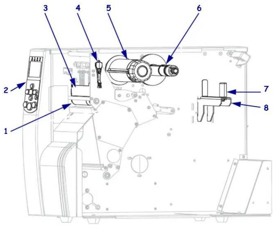
| 1 | Platen roller |
| 2 | Control panel |
| 3 | Printhead assembly |
| 4 | Printhead-open lever |
| 5 | Ribbon take-up spindle |
| 6 | Ribbon supply spindle |
| 7 | Media supply guide |
| 8 | Media supply hanger* |
* The media hanger varies by model. The 110Xi4 media hanger is shown.
Control Panel
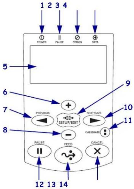
All controls and indicators for the printer are located on the control panel (Figure 3).
- The control panel Liquid Crystal Display (LCD) shows the operating status and printer parameters.
- The control panel buttons are used to control the printer operations and to set parameters.
- The control panel lights (LEDs) show the printer's operating status or indicate which control panel buttons are active.
Figure 3 · Location of Control Panel Buttons and Lights
flowchart
graph TD
    A["POWER"] --> B["PREVIOUS"]
    C["PAUSE"] --> D["SETUP/EXIT"]
    E["PULSE"] --> F["FEED"]
    G["CANCEL"] --> H["X"]
    I["DATA"] --> J["NEXT/SAVE"]
    K["ERROR"] --> L["+"]
    M["12 13 14"] --> N["->"]
    O["9"] --> P["10"]
    Q["11"] --> R["..."]
| 1 | Power light On | when the printer is on. | |
| 2 | PAUSE light On | when the printer is paused. | |
| 3 | Error light Off | Normal operation—no printer errors. | |
| Blinking A printer error exists. Check the LCD for more information. | |||
| 4 | Data light Off | Normal operation. No data being received or processed. | |
| On | The printer is processing data or is printing. No data is being received. | ||
| Blinking quickly | The printer is receiving data from or sending status information to the host computer. | ||
| 5 | LCD The control panel LCD functions differently in different printer modes.In Operating mode, the LCD displays the printer's status, sometimes in conjunction with a control panel light.In Pause mode, the printer stops printing temporarily.In Setup mode, you can use the control panel LCD to view or modify printer parameters (see Standard Control Panel Parameters on page 91).In Error mode, the LCD may display an alert or error message (see LCD Error Messages on page 131). | |
| 6 | PLUS (+) | Changes the parameter values. Common uses are to increase a value, to answer “yes,” to scroll through choices, or to change values while entering the printer password. |
| 7 | PREVIOUS | When in Setup mode, scrolls the LCD to the previous parameter. Press and hold to scroll quickly. |
| 8 | MINUS (-) | Changes the parameter values. Common uses are to decrease a value, to answer “no,” to scroll through choices, or to change the cursor position while entering the printer password. |
| 9 | SETUP/EXIT | Enters and exits Setup mode. |
| 10 | NEXT/SAVE | When in Setup mode, scrolls the LCD to the next parameter. Press and hold to scroll quickly.When exiting Setup mode, saves any changes that you made in the configuration and calibration sequence. |
| 11 | CALIBRATE | Calibrates the printer for the following:Media lengthMedia type (continuous or non-continuous)Print method (direct thermal or thermal transfer)Sensor values |
| 12 | PAUSE | Starts or stops printer operation, or removes error messages and clears the LCD.If the printer is idle, it enters Pause mode immediately.If the printer is printing, the label is completed before the printer pauses. |
| 13 | FEED | Forces the printer to feed one blank label each time the button is pressed.If the printer is idle or paused, the label is fed immediately.If the printer is printing, the label is fed after printing finishes. |
| 14 | CANCEL | Cancels print jobs when the printer is paused.Pressing CANCEL once has these effects:Cancels the label format that is currently printing.If no label format is printing, the next one to be printed is canceled.If no label formats are waiting to be printed, CANCEL is ignored.Pressing and holding CANCEL clears the printer's entire label format memory.When the formats are cleared, the DATA light turns off. |
2
Printer Setup

natural_image
Abstract black and white pattern with curved white and black shapes (no text or symbols)This section provides the tasks that you must complete and the issues that you must consider before you load and configure your printer.
Contents
Before You Begin 20
Handling the Printer 21
Unpack and Inspect the Printer 21
Store the Printer....21
Ship the Printer 21
Select a Site for the Printer 22
Select a Surface.... 22
Provide Proper Operating Conditions 22
Allow Proper Space 22
Provide a Data Source.... 22
Provide a Power Source 22
Select a Data Communication Interface. 23
Data Cables and Wireless Cards. 24
Connect the Printer to the Computer or Network. 24
Connect the Printer to a Power Source 28
Power Cord Specifications. 29
Types of Media. 31
Ribbon Overview 33
When to Use Ribbon 33
Coated Side of Ribbon.... 33
Before You Begin
Review this checklist, and resolve any issues before you set up or use your printer.
☐ Unpack and Inspect the Printer Have you unpacked the printer and inspected it for damage? If you have not, see Unpack and Inspect the Printer on page 21.
☐ Select a Site Have you selected an appropriate location for the printer? If you have not, see Select a Site for the Printer on page 22.
☐ Connect to a Data Source Have you determined how the printer will connect to a data source (usually a computer)? For more information, see Select a Data Communication Interface on page 23.
☐ Attach a Power Cord Do you have the correct power cord for your printer? If you are unsure, see Power Cord Specifications on page 29. To attach the power cord and connect the printer to a power source, see Connect the Printer to a Power Source on page 28.
☐ Select Media Do you have the correct media for your application? If you are unsure, see Types of Media on page 31.
☐ Select Ribbon Do you need to use ribbon, and is the appropriate ribbon available, if needed? If you are unsure, see Ribbon Overview on page 33.
Handling the Printer
This section describes how to handle your printer.
Unpack and Inspect the Printer
When you receive the printer, immediately unpack it and inspect for shipping damage.
- Save all packing materials.
- Check all exterior surfaces for damage.
- Raise the media door, and inspect the media compartment for damage to components.
If you discover shipping damage upon inspection:
- Immediately notify the shipping company and file a damage report.
- Keep all packaging material for shipping company inspection.
- Notify your authorized Zebra reseller

Important • Zebra Technologies Corporation is not responsible for any damage incurred during the shipment of the equipment and will not repair this damage under warranty.
Store the Printer
If you are not placing the printer into immediate operation, repackage it using the original packing materials. You may store the printer under the conditions shown in Table 1.
Table 1 • Storage Temperature and Humidity
| Temperature Relative Humidity | |
| -40^ to 140^ ( -40^ to 60^ ) 5% to 85% non-condensing | |
Ship the Printer
If you must ship the printer:
- Turn off (O) the printer, and disconnect all cables.
- Remove any media, ribbon, or loose objects from the printer interior.
- Close the printhead.
- Carefully pack the printer into the original container or a suitable alternate container to avoid damage during transit. A shipping container can be purchased from Zebra if the original packaging has been lost or destroyed.
Select a Site for the Printer
Consider the following when selecting an appropriate location for your printer.
Select a Surface
Select a solid, level surface of sufficient size and strength to accommodate the printer and other equipment (such as a computer), if necessary. The choices include a table, countertop, desk, or cart. For the printer's weight and dimensions, see General Specifications on page 158.
Provide Proper Operating Conditions
This printer is designed to function in a wide range of environmental and electrical conditions, including a warehouse or factory floor. For more information on the required conditions, see General Specifications on page 158.
Table 2 shows the temperature and relative humidity requirements for the printer when it is operating.
Table 2 · Operating Temperature and Humidity
| Mode Temperature Relative Humidity | ||
| Thermal Transfer 41° to 105°F (5° to 40°C) 20 to 85% non-condensing. | ||
| Direct Thermal 32° to 105°F (0° to 40°C) 20 to 85% non-condensing | ||
Allow Proper Space
The printer should have enough space around it for you to be able to open the media door. To allow for proper ventilation and cooling, leave open space on all sides of the printer.

Caution • Do not place any padding or cushioning material behind or under the printer because this restricts air flow and could cause the printer to overheat.
Provide a Data Source
If the printer will be located away from the data source (such as a computer), the selected site must provide the appropriate connections to that data source. For more information on the types of communication interfaces and their limitations, see Select a Data Communication Interface on page 23.
Provide a Power Source
Place the printer within a short distance of a power outlet that is easily accessible.
Select a Data Communication Interface
Table 3 provides basic information about data communication interfaces that you can use to connect your printer to a computer. You may send label formats to the printer through any data communication interface that is available. Select an interface that is supported by both your printer and your computer or your Local Area Network (LAN).
Table 3 · Characteristics of the Data Communication Interfaces
| Interface | Standard or Optional on Printer | Characteristics |
| RS-232 Serial Standard | • Maximum cable | length of 50 ft (15.24 m).You may need to change printer parameters to match the host computer.You need to use a null-modem adaptor to connect to the printer if using a standard modem cable. |
| IEEE 1284 Bidirectional Parallel | Standard • Maximum cable length of 10 ft (3 m).Recommended cable length of 6 ft (1.83 m).An Ethernet print server (if installed) takes up or covers this port on the printer.No printer parameter changes required to match the host computer. | |
| USB Standard • Maximum cable length of 16.4 ft (5 m).No printer parameter changes required to match the host computer. | ||
| Twinax/Coax Optional | • Acts as an EBCDIC to ASCII converter.Allows for the ability to communicate with the printer in an IBM® AS/400® environment. | |
| Internal wired Ethernet print server | Optional • Can print to the printer from any computer on your LAN.Can communicate with the printer through the printer's web pages when in ZPL mode.Computer must be equipped with an Ethernet board.The printer must be configured to use your LAN. | |
| Wireless Ethernet print server | Optional • Can print to the printer from any computer on your Wireless Local Area Network (WLAN).Can communicate with the printer through the printer's web pages when in ZPL mode.The printer must be configured to use your WLAN. | |
Data Cables and Wireless Cards
You must supply all data cables or wireless cards for your application.
Data Cables Ethernet cables do not require shielding, but all other data cables must be fully shielded and fitted with metal or metallized connector shells. Unshielded data cables may increase radiated emissions above the regulated limits.
To minimize electrical noise pickup in the cable:
- Keep data cables as short as possible.
- Do not bundle the data cables tightly with the power cords.
- Do not tie the data cables to power wire conduits.
Wireless Cards For supported wireless cards, refer to the ZebraNet Wireless User Guide. A copy of the manual is available at http://www.zebra.com/manuals or on the user CD that came with your printer.
Connect the Printer to the Computer or Network
Table 4 shows how to connect the different types of data cables to your printer and computer. The connectors on the back of your computer may be in different locations than on the sample computer shown in this section.
Caution • Ensure that the printer power is off (O) before connecting data communications cables. Connecting a data communications cable while the power is on (I) may damage the printer.
Table 4 · Connecting the Printer to a Computer or Network
| Interface Connection and Configuration | |
| RS-232 Serial The baud rate, number of data and stop bits, the parity, and the XON/XOFF or DTR control must match those of the host computer. See Standard Control Panel Parameters on page 91 to view or change these parameters. | 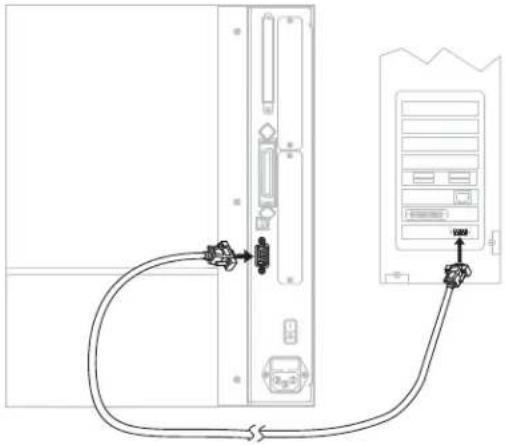 |
| IEEE 1284 Bidirectional Parallel | No additional configuration is necessary. An Ethernet print server (if installed) takes up or covers this port on the printer. |
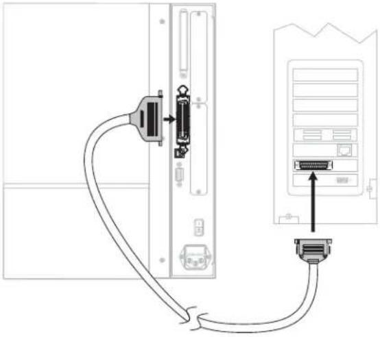 | |
| USB No additional configuration is necessary. | Caution • Be careful not to plug the USB cable into the wired Ethernet print server connector on the printer because doing so will damage the connector. |
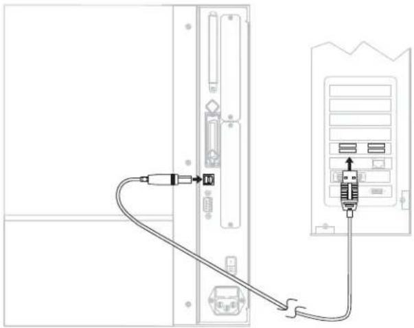 | |
| Twinax/Coax No additional configuration is necessary. To purchase this option, contact your authorized Zebra reseller. | 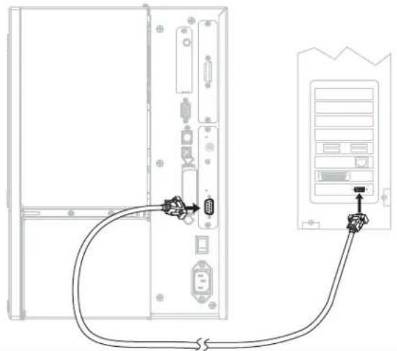 |
| Internal wired Ethernet print server | Refer to the ZebraNet 10/100 Print Server User and Reference Guide for configuration instructions. A copy of this manual is available at http://www.zebra.com/manuals or on the user CD that came with your printer. Note • To use this connection, you may need to remove a factory-installed plug that is designed to keep someone from accidentally plugging a USB connector into this port. Note • To use this connection, you may need to remove a factory-installed plug that is designed to keep someone from accidentally plugging a USB connector into this port.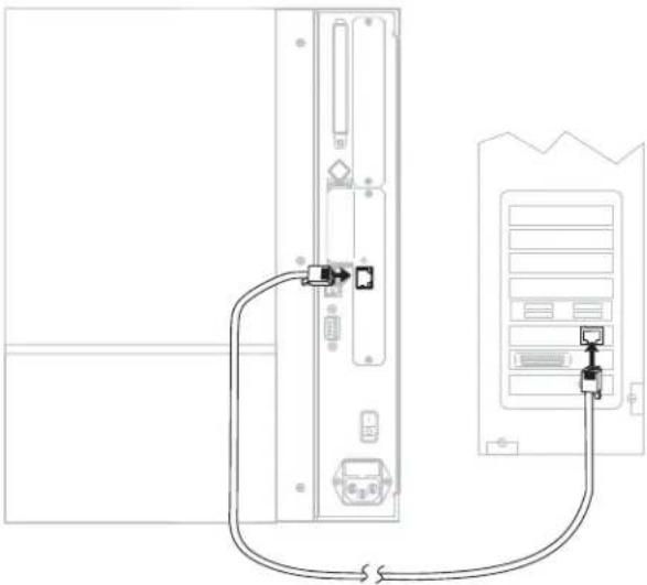 |
| Wireless Ethernet print server | Refer to the ZebraNet Wireless User Guide for configuration instructions. A copy of this manual is available at http://www.zebra.com/manuals or on the user CD that came with your printer. |
Connect the Printer to a Power Source
The AC power cord must have a three-prong female connector on one end that plugs into the mating AC power connector at the rear of the printer. If a power cable was not included with your printer, refer to Power Cord Specifications on page 29.

Caution • For personnel and equipment safety, always use an approved three-conductor power cord specific to the region or country intended for installation. This cord must use an IEC 320 female connector and the appropriate region-specific three-conductor grounded plug configuration.
To connect the printer to a power source, complete these steps:
- Toggle the printer power switch to the off (O) position.
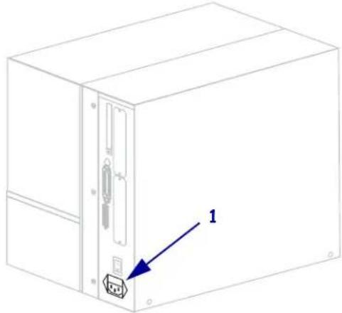
- Plug the power cord into the AC power connector (1) on the rear of the printer.
natural_image
Line drawing of a server rack unit with an attached port and labeled component (no text or symbols beyond the label)- Plug the other end of the power cord into a power outlet near the printer.
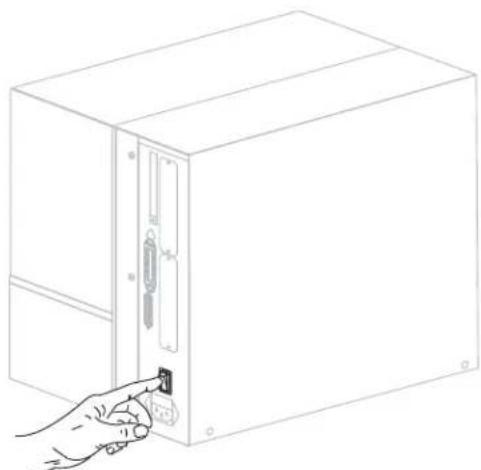
- Turn on (I) the printer.
natural_image
Line drawing of a hand inserting a small component into a rectangular device (no text or symbols)The control panel LCD and lights activate, indicating that the printer is booting up.
Power Cord Specifications

Caution • For personnel and equipment safety, always use an approved three-conductor power cord specific to the region or country intended for installation. This cord must use an IEC 320 female connector and the appropriate region-specific, three-conductor grounded plug configuration.
Depending on how your printer was ordered, a power cord may or may not be included. If one is not included or if the one included is not suitable for your requirements, see Figure 4 and refer to the following guidelines:
• The overall cord length must be less than 9.8 ft. (3 m).
• The cord must be rated for at least 10 A, 250 V.
- The chassis ground (earth) must be connected to ensure safety and reduce electromagnetic interference.
Figure 4 · Power Cord Specifications
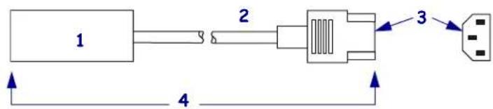
| 1 | AC power plug for your country—This should bear the certification mark of at least one of the known international safety organizations (Figure 5). |
| 2 | 3-conductor HAR cable or other cable approved for your country. |
| 3 | IEC 320 connector—This should bear the certification mark of at least one of the known international safety organizations (Figure 5). |
| 4 | Length ≤ 9.8 ft. (3 m). Rating 10 Amp, 250 VAC. |
Figure 5 • International Safety Organization Certifications

Install Control Panel Keypad Cover
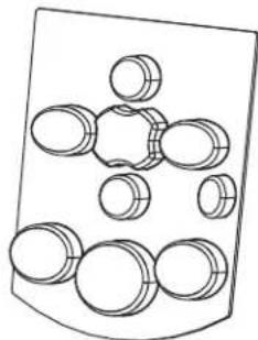
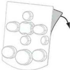
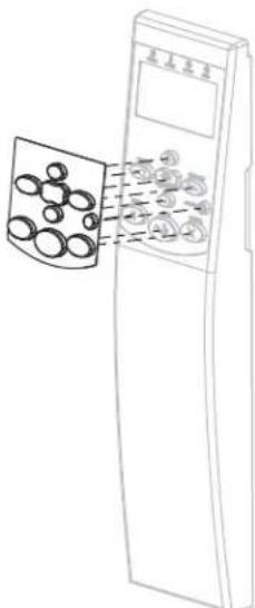
A protective cover for the control panel keypad is provided with your printer (Figure 6). Install this optional cover if your printer will operate in a moist or dirty environment. This will help to protect the keypad from damage.
Figure 6 • Control Panel Keypad Cover
natural_image
Diagram of a mechanical component with multiple circular holes and a curved base (no text or symbols)To install the control panel keypad cover, complete these steps:
- Remove the paper backing from the control panel keypad cover to expose the adhesive.
natural_image
Diagram of a container with multiple circular objects and an arrow indicating rotation (no text or symbols)- Carefully align the cover over the keypad. Press to make the cover adhere to the printer.
Types of Media

Important •
Your printer can use various types of media:
- Standard media—Most standard media uses an adhesive backing that sticks individual labels or a continuous length of labels to a liner.
- Tag stock—Tags are usually made from a heavy paper. Tag stock does not have adhesive or a liner, and it is typically perforated between tags.
- Radio frequency identification (RFID) “smart” media—RFID media can be used in a printer that is equipped with an RFID reader/encoder. RFID labels are made from the same materials and adhesives as non-RFID labels. Each label has an RFID transponder (sometimes called an “inlay”), made of a chip and an antenna,
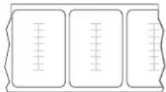
embedded between the label and the liner. The shape of the transponder varies by manufacturer and is visible through the label. All “smart” labels have memory that can be read, and many have memory that can be encoded.
Table 5 describes roll and fanfold media. Roll media is loaded into the printer while fanfold media may be located inside or outside of the printer.
Table 5 · Roll and Fanfold Media
| Media Type How It | Looks Description | |
| Non-Continuous Roll Media | 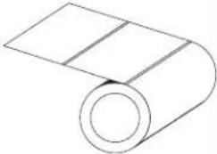 | Roll media is wound on a 3-in. (76-mm) core. Individual labels are separated by one or more of the following methods:• Web media separates labels by gaps, holes, or notches.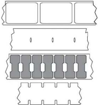 • Black mark media uses pre-printed black marks on the back side of the media to indicate label separations. • Black mark media uses pre-printed black marks on the back side of the media to indicate label separations.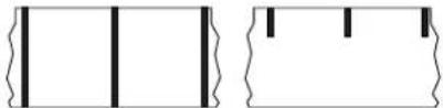 • Perforated media has perforations that allow the labels or tags to be separated from each other easily. The media may also have black marks or other separations between labels or tags.[IMAGE] • Perforated media has perforations that allow the labels or tags to be separated from each other easily. The media may also have black marks or other separations between labels or tags.[IMAGE] |
| Non-Continuous Fanfold Media | 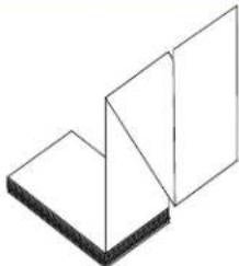 | Fanfold media is folded in a zigzag pattern. Fanfold media can have the same label separations as non-continuous roll media. The separations would fall on or near the folds. |
| Continuous Roll Media | 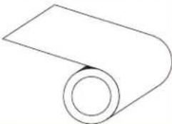 | Roll media is wound on a 3-in. (76-mm) core.Continuous roll media does not have gaps, holes, notches, or black marks to indicate label separations. This allows the image to be printed anywhere on the label. Sometimes a cutter is used to cut apart individual labels. |
Ribbon Overview
Ribbon is a thin film that is coated on one side with wax, resin, or wax resin, which is transferred to the media during the thermal transfer process. The media determines whether you need to use ribbon and how wide the ribbon must be.
When ribbon is used, it must be as wide as or wider than the media being used. If the ribbon is narrower than the media, areas of the printhead are unprotected and subject to premature wear.
When to Use Ribbon
Thermal transfer media requires ribbon for printing while direct thermal media does not. To determine if ribbon must be used with a particular media, perform a media scratch test.
To perform a media scratch test, complete these steps:
- Scratch the print surface of the media rapidly with your fingernail.
- Did a black mark appear on the media?
| If a black mark... Then the media is... | |
| Does not appear on the media | Thermal transfer. A ribbon is required. |
| Appears on the media | Direct thermal. No ribbon is required. |
Coated Side of Ribbon
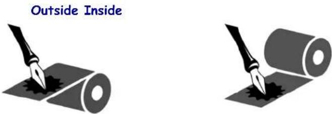
Ribbon can be wound with the coated side on the inside or outside (Figure 7). This printer can only use ribbon that is coated on the outside. If you are unsure which side of a particular roll of ribbon is coated, perform an adhesive test or a ribbon scratch test to determine which side is coated.
Figure 7 • Ribbon Coated on Outside or Inside
Adhesive Test
If you have labels available, perform the adhesive test to determine which side of a ribbon is coated. This method works well for ribbon that is already installed.
To perform an adhesive test, complete these steps:
-
Peel a label from its liner.
-
Press a corner of the sticky side of the label to the outer surface of the roll of ribbon.
-
Peel the label off of the ribbon.
-
Observe the results. Did flakes or particles of ink from the ribbon adhere to the label?
| If ink from the ribbon... Then... | |
| Adhered to the label The ribbon is coated on the outside and can be used in this printer. | |
| Did not adhere to the label | The ribbon is coated on the inside and cannot be used in this printer. To verify this, repeat the test on the other surface of the roll of ribbon. |
Ribbon Scratch Test
Perform the ribbon scratch test when labels are unavailable.
To perform a ribbon scratch test, complete these steps:
-
Unroll a short length of ribbon.
-
Place the unrolled section of ribbon on a piece of paper with the outer surface of the ribbon in contact with the paper.
-
Scratch the inner surface of the unrolled ribbon with your fingernail.
-
Lift the ribbon from the paper.
-
Observe the results. Did the ribbon leave a mark on the paper?
| If the ribbon... Then... | |
| Left a mark on the paper | The ribbon is coated on the outer surface. |
| Did not leave a mark on the paper | The ribbon is coated on the inner surface and cannot be used in this printer. To verify this, repeat the test on the other surface of the roll of ribbon. |
3
Operations

natural_image
Abstract black and white pattern with curved white and black shapes (no text or symbols)This section provides the procedures for loading and calibrating the printer.

Note • Complete the tasks and resolve the issues in Printer Setup on page 19 before operating the printer.
Contents
Print Modes and Printer Options 36
Print Mode Descriptions and Printer Requirements. 36
Media Paths 37
Prepare the Media for Loading. 39
Load Media in Tear-Off Mode. 43
Load Media in Peel-Off Mode 47
Load Media in Cutter Mode 54
Load Media in Rewind Mode 59
Remove Media Liner from the Rewind Spindle 66
Load Ribbon....68
Remove Used Ribbon 73
Calibrate the Printer 75
Adjust Transmissive Media Sensors 77
Upper Media Sensor 77
Lower Media Sensor 80
Adjust Printhead Pressure and Toggle Position....81
Toggle Position Adjustment 81
Printhead Pressure Adjustment 82
Print Modes and Printer Options
The printer can use different print modes and options for label removal (Table 6). Use a print mode that matches the media being used and the printer options available. For more information on the types of media, see Types of Media on page 31. To select a print mode, see Select Print Mode on page 93.
Print Mode Descriptions and Printer Requirements
Table 6 · Print Modes and Printer Options
| Print Mode When to Use/Printer Options Required Printer Actions | ||
| Tear-Off (default setting) | Use for most applications. This mode can be used with any printer options and most media types. | The printer prints label formats as it receives them. The printer operator can tear off the printed labels any time after they print. |
| Peel-Off Use only | if the printer has the Peel-Off or Rewind option. | The printer peels the label from the liner during printing and then pauses until the label is removed. The backing is wound on the rewind spindle, but the rewind plate is not used. |
| Cutter Use if the printer has a cutter option when you want the labels to be cut apart. | The printer prints a label and then cuts it free. | |
| Delayed Cut Use if the printer has a cutter option when you want the printer to cut the labels apart at a signal. | The printer prints a label, pauses, and cuts the label when it receives the ~JK (delayed cut) ZPL command. | |
| Applicator Use only if the printer is used with a machine that applies labels. | The printer prints a label when it receives a signal from the applicator. | |
| Rewind Use if the printer has the Rewind option and you want the labels to rewind onto a core. | The printer prints without pausing between labels. The media is wound onto a core after printing. The rewind plate is used. If your printer has a cutter, the media is threaded through the cutter, but the labels are not cut. | |
Media Paths
Table 7 shows the media paths for print mode and printer option combinations using roll media. Fanfold media uses the same print modes and printer options as roll media. RFID printers can use all of these printer options and have the same media paths.
Table 7 • Media Paths for Print Modes with Various Printer Options
| Print Mode Printer Option | Media Path | |
| Tear-Off Printers with any printer options can use Tear-Off mode | 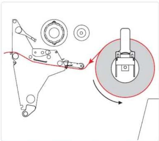 | |
| Peel-Off or Applicator | Rewind (shown) or Peel (not shown) | 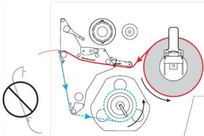 |
Red solid lines = media, Blue dotted lines = backing only
Table 7 • Media Paths for Print Modes with Various Printer Options (Continued)
| Print Mode Printer Option | Media Path |
| Cutter Cutter | 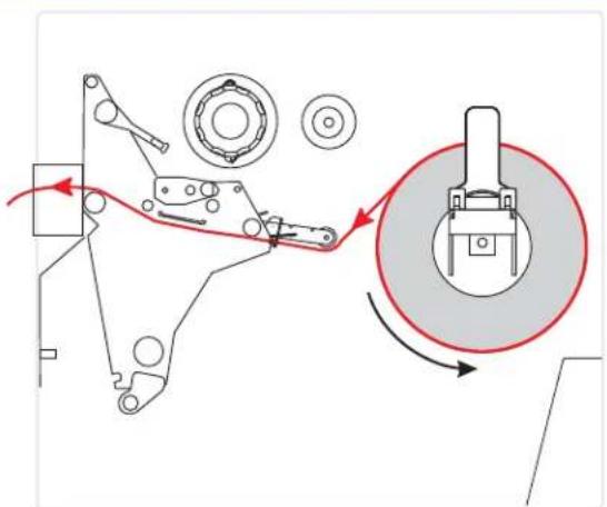 |
| Rewind Rewind (without Cutter option) | 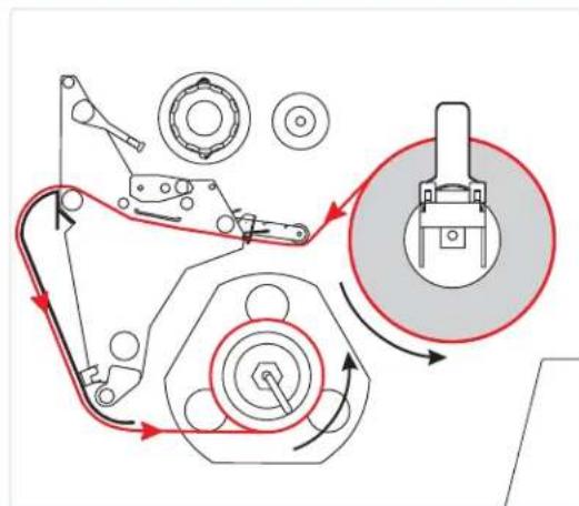 |
Red solid lines = media, Blue dotted lines = backing only
Prepare the Media for Loading
You can use roll media or fanfold media in your printer. Roll media hangs on and is loaded from the media supply hanger. Fanfold media is stored away from or in the bottom of the printer and can drape across the media supply hanger.
Roll Media
To place roll media on the media supply hanger, complete these steps:
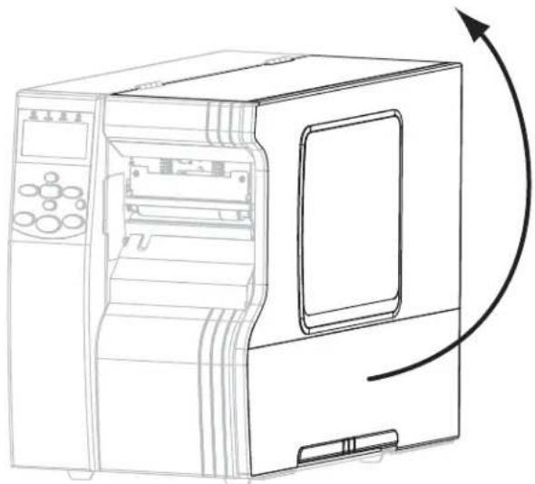
- Raise the media door.
natural_image
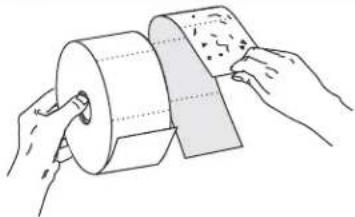
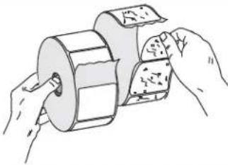
Line drawing of a machine with control panel and door, showing internal components and an arrow indicating rotation (no text or symbols)- Remove and discard any tags or labels that are dirty or that are held by adhesives or tape.
| Tag Stock Labels | |
 |  |
- Insert the media into the printer.
110Xi4 Other Xi4 Models
a. Pull out the media supply guide as far as it goes.
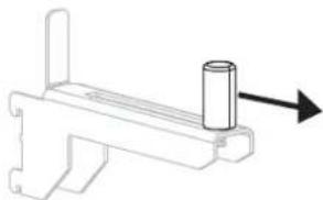
natural_image
Technical line drawing of a mechanical bracket with a cylindrical component and an arrow indicating direction (no text or symbols)b. Place the roll of media on the media supply hanger. Push the roll as far back as it will go.
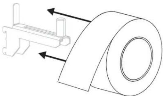
natural_image
Technical line drawing of a mechanical assembly with a roller and bracket (no text or symbols)c. Slide in the media supply guide until it touches the edge of the roll.
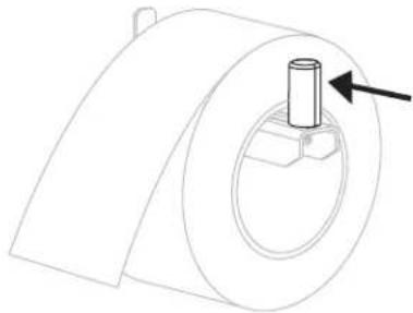
natural_image
Technical line drawing of a mechanical component with a cylindrical shaft and mounting base (no text or symbols)a. Slide out and flip down the media supply guide.
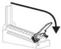
b. Place the roll of media on the media supply hanger. Push the roll back as far as it will go.
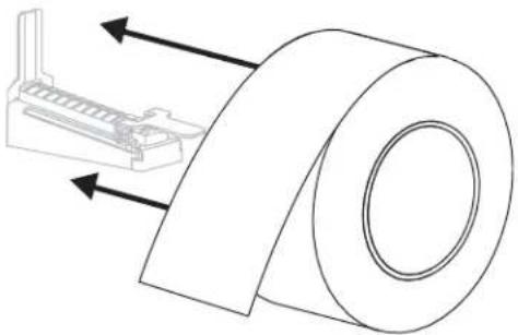
natural_image
Technical line drawing of a mechanical component with directional arrows indicating movement (no text or symbols)c. Flip up the media supply guide.
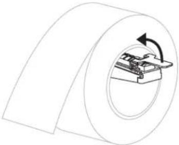
natural_image
Diagram of a cylindrical mechanical component with an internal mechanism and rotation arrow (no text or symbols)d. Slide in the media supply guide until it touches the edge of the roll.
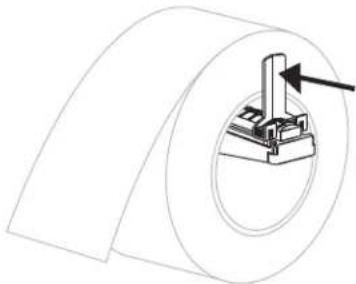
natural_image
Technical line drawing of a cylindrical mechanical component with a central bracket and an arrow indicating direction (no text or symbols)- Continue with the media loading procedure for the desired print mode.
Fanfold Media
You can store fanfold media behind the printer (rear feed) or under the printer (bottom feed). Using the media supply hanger is optional.
To load fanfold media, complete these steps:
- Raise the media door.
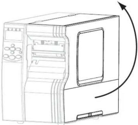
natural_image
Line drawing of a computer with an open door and control panel, showing a curved arrow indicating rotation (no text or symbols present)- Thread the fanfold media through the rear access slot (1) or the bottom access slot (2).
| If using... Then use this access slot... | |
| Rear feed(shown using the media supply hanger) | 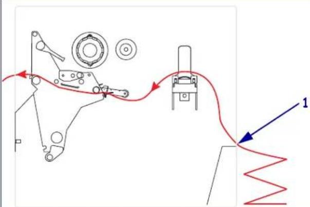 |
| Bottom feed(shown without using the media supply hanger) | 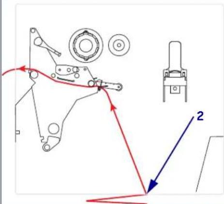 |
- Do you wish to use the media supply hanger?
| If... Then... | ||
| No Continue with the media loading procedure for the desired print mode. | ||
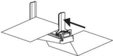
| Yes | a.Slide out and flip down the media supply guide.b.Drape the media over the media supply hanger. | |
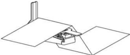 4. Flip up the media supply guide, and then slide it in until it touches the edge of the media. 4. Flip up the media supply guide, and then slide it in until it touches the edge of the media. | ||
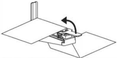 |  | |
Load Media in Tear-Off Mode
Follow these instructions to operate the printer in Tear-Off mode.
Caution • While performing any tasks near an open printhead, remove all rings, watches, hanging necklaces, identification badges, or other metallic objects that could touch the printhead. You are not required to turn off the printer power when working near an open printhead, but Zebra recommends it as a precaution. If you turn off the power, you will lose all temporary settings, such as label formats, and you must reload them before you resume printing.
- Set the printer to Tear-Off mode. See Select Print Mode on page 93 for instructions.
- Insert media into the printer. See Prepare the Media for Loading on page 39 for instructions.
- Open the printhead assembly by rotating the printhead-open lever (1) counter-clockwise.
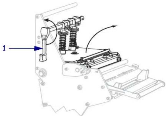
- Loosen the thumb screw (not visible from this angle) that is located on the bottom of the outer media guide (1).
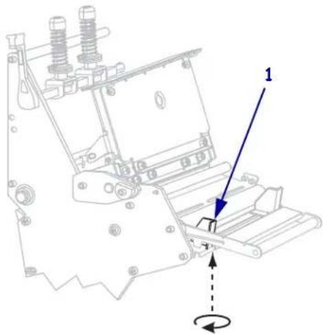
natural_image
Technical diagram of a mechanical assembly with labeled component '1' and rotation arrow (no text or symbols beyond labels)- Slide the outer media guide (1) all the way out.
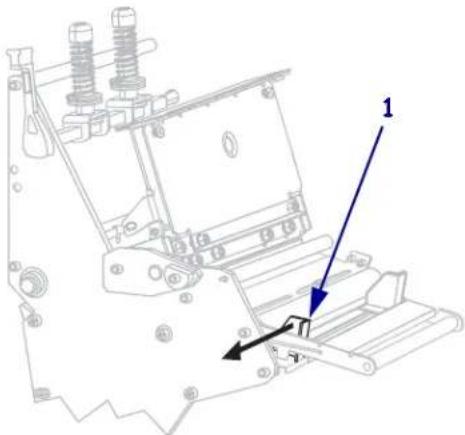
natural_image
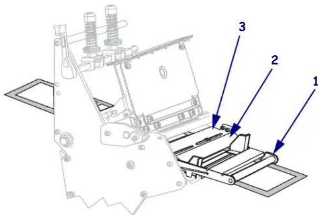
Technical line drawing of a mechanical assembly with labeled component '1' and directional arrows (no text or symbols beyond labels)- If your printer includes a media dancer assembly (1), thread the media under the media dancer assembly roller. For all printers, thread the media under the media guide roller (2) and then the upper media sensor (3).

Important • Make sure that you thread the media under these components. If you thread the media over the them, the media obstructs the ribbon sensor and causes a false RIBBON OUT error.
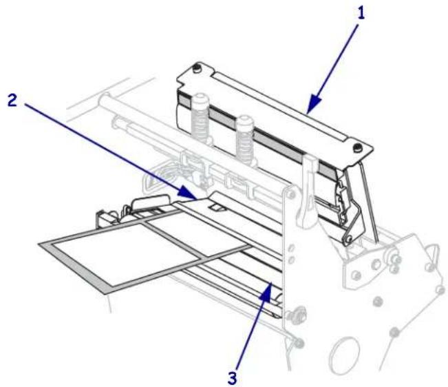
- Push the media forward until it passes under the printhead assembly (1), under the snap plate (2), and then over the platen roller (3).
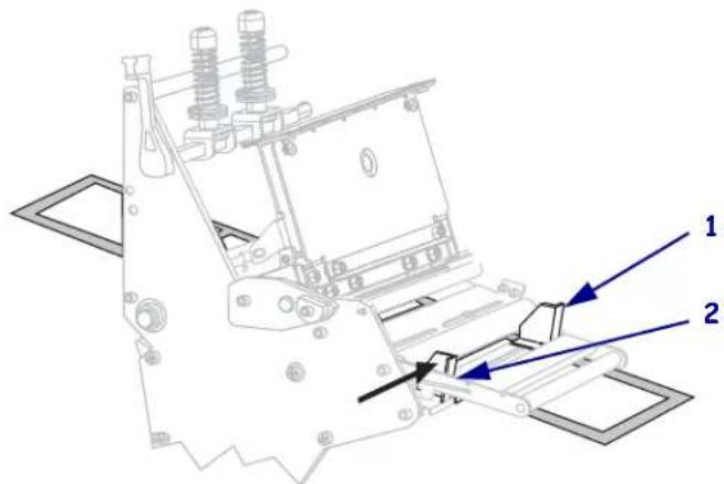
- Align the media with the inner media guide (1). Slide in the outer media guide (2) until it just touches the edge of the media.
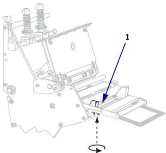
- Tighten the thumb screw (not visible from this angle) that is located on the bottom of the outer media guide (1).
natural_image
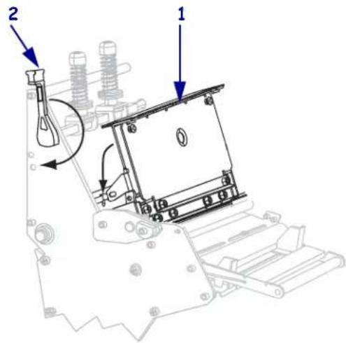
Technical line drawing of a mechanical assembly with no visible text or symbols- Push down the printhead assembly (1), and then rotate the printhead-open lever (2) clockwise until it locks into place.
Load Media in Peel-Off Mode
Peel-Off mode (Figure 8) advances one label at a time. The printer does not print another label until the first label is removed. The TAKE LABEL light flashes until the label is removed. The backing is wound on the rewind spindle, but the rewind plate is not used.
Figure 8 · Media Loaded in Peel-Off Mode
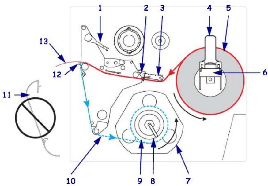
| 1 | Printhead-open lever |
| 2 | Media guide |
| 3 | Media guide roller |
| 4 | Media supply guide |
| 5 | Media |
| 6 | Media supply hanger |
| 7 | Guide plate |
| 8 | Spindle hook |
| 9 | Rewind spindle |
| 10 | Label backing |
| 11 | Rewind plate (removed)* |
| 12 | Tear-off bar |
| 13 | Printed label |
* In new printers, remove the protective plastic covering from the rewind plate before using.
Caution • While performing any tasks near an open printhead, remove all rings, watches, hanging necklaces, identification badges, or other metallic objects that could touch the printhead. You are not required to turn off the printer power when working near an open printhead, but Zebra recommends it as a precaution. If you turn off the power, you will lose all temporary settings, such as label formats, and you must reload them before you resume printing.
To set up the printer in Peel-Off mode, complete these steps:
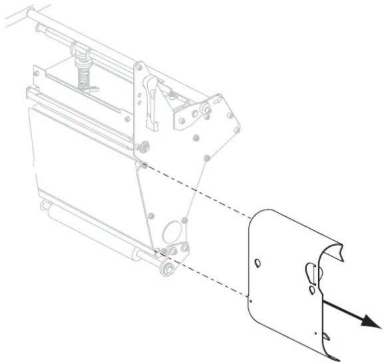
- Remove the rewind plate (if installed) from the front of the printer. Store it on the two mounting screws on the inside of the printer base.
natural_image
Technical line drawing of a mechanical assembly with no visible text or symbols-
Set the printer to Peel-Off mode. See Select Print Mode on page 93 for instructions.
-
Insert media into the printer. See Prepare the Media for Loading on page 39 for instructions.
-
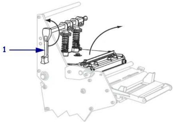
Open the printhead assembly by rotating the printhead-open lever (1) counter-clockwise.
natural_image
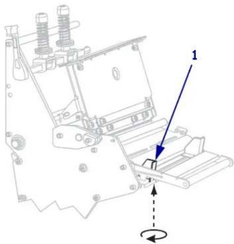
Technical line drawing of a mechanical assembly with springs and rollers (no text or symbols)- Loosen the thumb screw (not visible from this angle) that is located on the bottom of the outer media guide (1).
natural_image
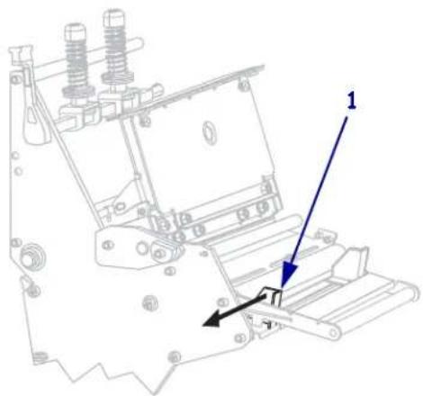
Technical line drawing of a mechanical assembly with no visible text or symbols- Slide the outer media guide (1) all the way out.

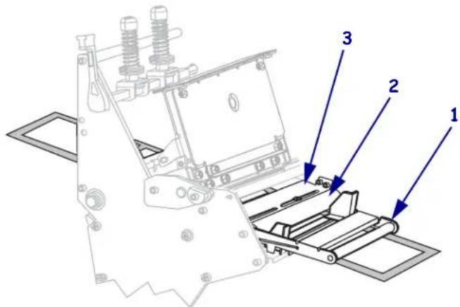
- If your printer includes a media dancer assembly (1), thread the media under the media dancer assembly roller. For all printers, thread the media under the media guide roller (2) and then the upper media sensor (3).
Important • Make sure that you thread the media under these components. If you thread the media over the them, the media obstructs the ribbon sensor and causes a false RIBBON OUT error.
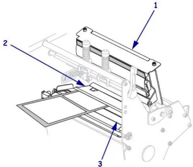
- Push the media forward until it passes under the printhead assembly (1), under the snap plate (2), and then over the platen roller (3).
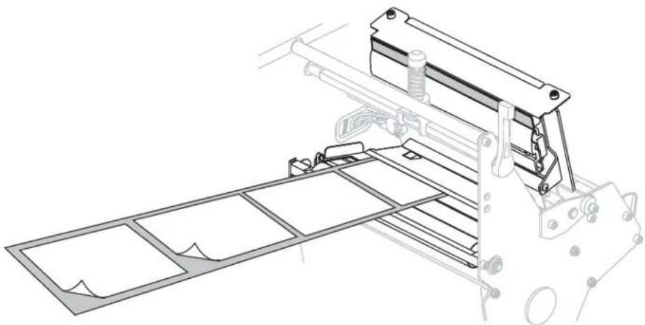
- Extend approximately 36 in. (920 mm) of media out of the printer. Remove and discard the labels from this exposed media.
natural_image
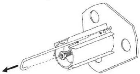
Technical line drawing of a mechanical assembly with ladder and frame components (no text or symbols)- Remove the hook from the rewind spindle.
natural_image
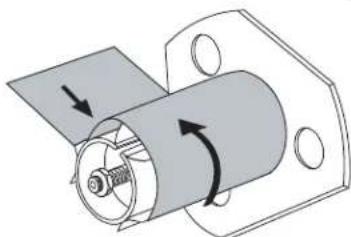
Technical line drawing of a mechanical assembly with no visible text or symbols- If you are using a core, slide it onto the rewind spindle until it is flush against the guide plate.

Note • A core is not required.
- Wind the media liner counterclockwise around the rewind spindle.
natural_image
Mechanical assembly diagram showing a cylindrical component with rotating arrows indicating motion (no text or symbols)a. Reinstall the hook. Insert the short end of the hook into the hole in the center of the adjusting nut (1). Insert the long end of the hook into the small hole on the guide plate (2).
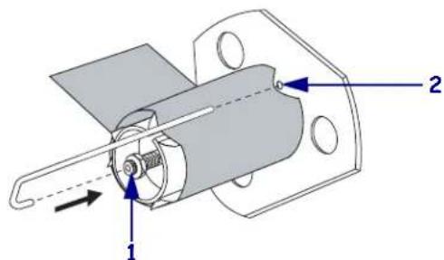
b. Rotate the spindle counterclockwise several turns to wind the media liner over the hook and remove any slack.
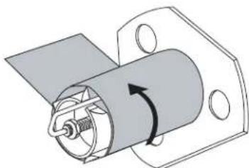
natural_image
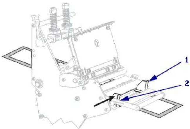
Mechanical assembly diagram showing a cylindrical component with a rotating arrow, mounted on a flanged base (no text or symbols)- Align the media with the inner media guide (1). Slide in the outer media guide (2) until it just touches the edge of the media.
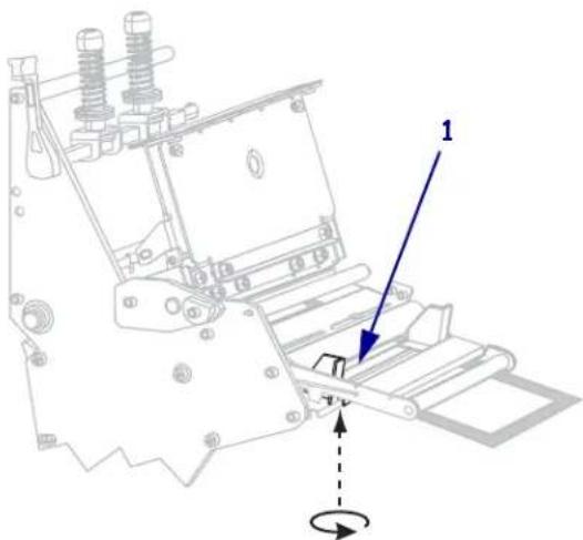
- Tighten the thumb screw (not visible from this angle) that is located on the bottom of the outer media guide (1).
natural_image
Technical line drawing of a mechanical assembly with no visible text or symbols- Push down the printhead assembly (1), and then rotate the printhead-open lever (2) clockwise until it locks into place.
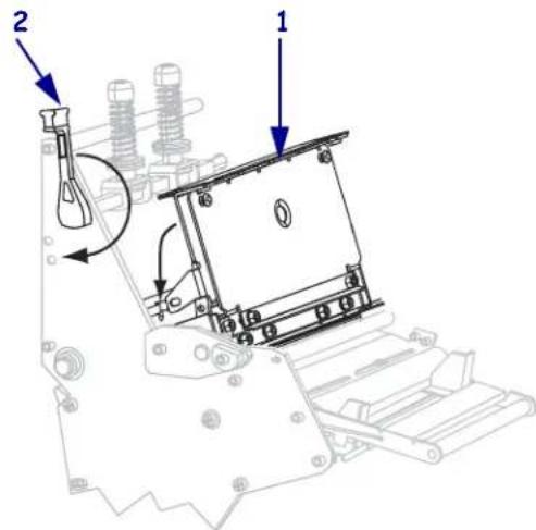
The backing winds on the rewind spindle or core.
- For instructions for removing the backing from the rewind spindle, see Remove Media Liner from the Rewind Spindle on page 66.
Load Media in Cutter Mode
A cutter is a rotating knife with a self-sharpening blade that is attached to the front of the printer. The cutter is used to cut individual labels as they are printed.
Figure 9 shows the printer loaded with labels in Cutter mode.
Figure 9 • Media Loaded in Cutter Mode
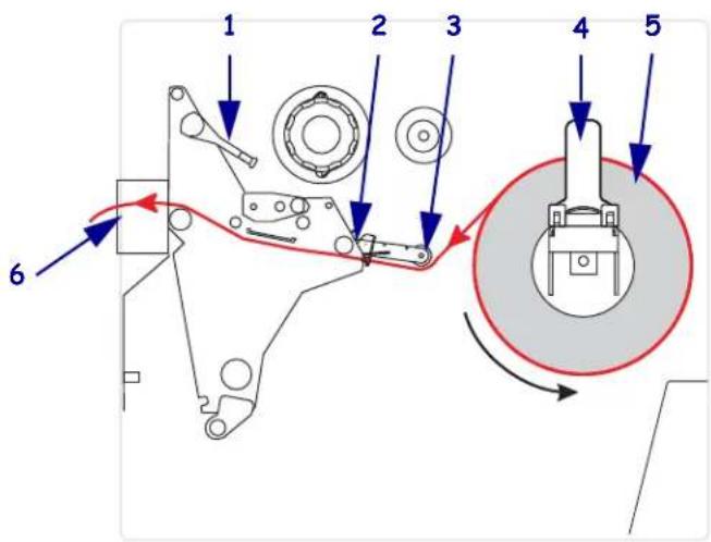
| 1 | Printhead-open lever |
| 2 | Media guide |
| 3 | Media guide roller |
| 4 | Media supply guide |
| 5 | Media |
| 6 | Cutter |
Caution • While performing any tasks near an open printhead, remove all rings, watches, hanging necklaces, identification badges, or other metallic objects that could touch the printhead. You are not required to turn off the printer power when working near an open printhead, but Zebra recommends it as a precaution. If you turn off the power, you will lose all temporary settings, such as label formats, and you must reload them before you resume printing.
To set up the printer in Cutter mode, complete these steps:
-
Set the printer to Cutter mode. See Select Print Mode on page 93 for instructions.
-
Insert media into the printer. See Prepare the Media for Loading on page 39 for instructions.
-
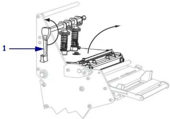
Open the printhead assembly by rotating the printhead-open lever (1) counter-clockwise.
natural_image
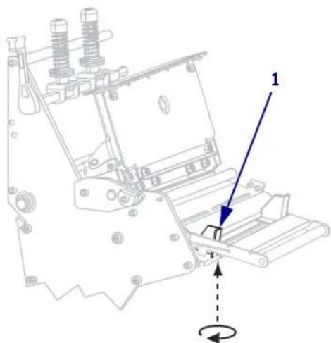
Technical line drawing of a mechanical assembly with springs and rollers (no text or symbols)- Loosen the thumb screw (not visible from this angle) that is located on the bottom of the outer media guide (1).
natural_image
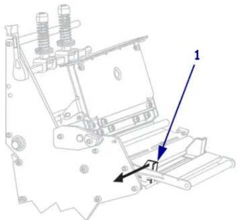
Technical line drawing of a mechanical assembly with no visible text or symbols- Slide the outer media guide (1) all the way out.
natural_image
Technical line drawing of a mechanical assembly with no visible text or symbols
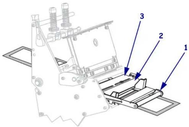
- If your printer includes a media dancer assembly (1), thread the media under the media dancer assembly roller. For all printers, thread the media under the media guide roller (2) and then the upper media sensor (3).
Important • Make sure that you thread the media under these components. If you thread the media over the them, the media obstructs the ribbon sensor and causes a false RIBBON OUT error.

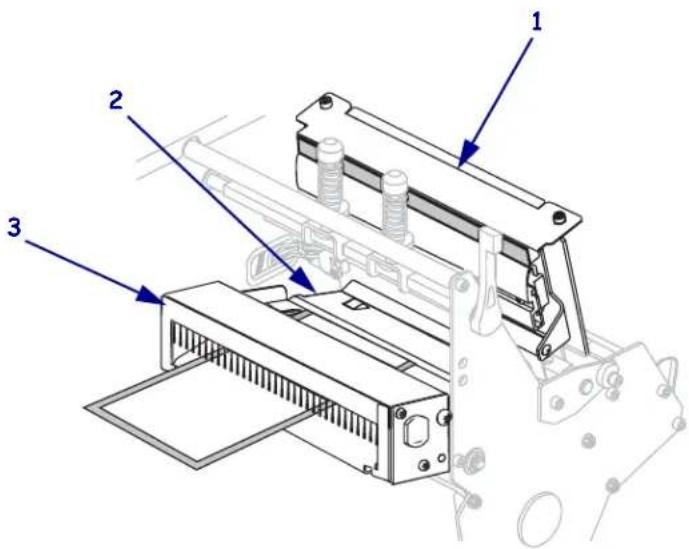
- Caution • The cutter blade is sharp. Do not touch or rub the blade with your fingers.
Thread the media forward until it passes under the printhead assembly (1), under the snap plate (2), and through the cutter assembly (3).
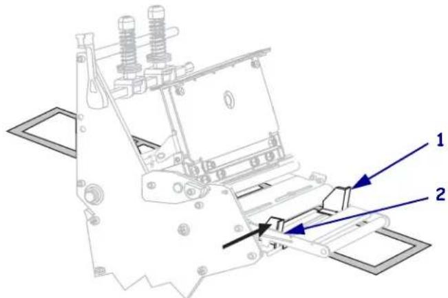
- Align the media with the inner media guide (1). Slide in the outer media guide (2) until it just touches the edge of the media.
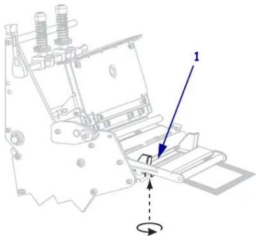
- Tighten the thumb screw (not visible from this angle) that is located on the bottom of the outer media guide (1).
natural_image
Technical line drawing of a mechanical assembly with no visible text or symbols- Push down the printhead assembly (1), and then rotate the printhead-open lever (2) clockwise until it locks into place.
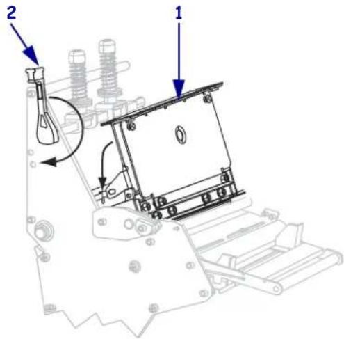
Load Media in Rewind Mode
Rewind mode (Figure 10) allows the media to be wound on a core after printing. This section shows how to load media for Rewind mode in printers that do not have a Cutter option.
Figure 10 • Media Loaded in Rewind Mode
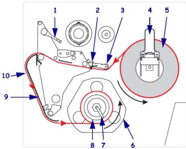
| 1 | Printhead-open lever |
| 2 | Media guide |
| 3 | Media guide roller |
| 4 | Media supply guide |
| 5 | Labels |
| 6 | Guide plate |
| 7 | Spindle hook |
| 8 | Rewind spindle |
| 9 | Rewind plate (for Rewind mode only)* |
| 10 | Printed labels |
* In new printers, remove the protective plastic covering from the rewind plate before using.
Caution • While performing any tasks near an open printhead, remove all rings, watches, hanging necklaces, identification badges, or other metallic objects that could touch the printhead. You are not required to turn off the printer power when working near an open printhead, but Zebra recommends it as a precaution. If you turn off the power, you will lose all temporary settings, such as label formats, and you must reload them before you resume printing.
To set up the printer in Rewind mode, complete these steps:
- Remove the rewind plate from its storage location inside the printer.
- Position the rewind plate so that the lip on the attached hook plate points down.
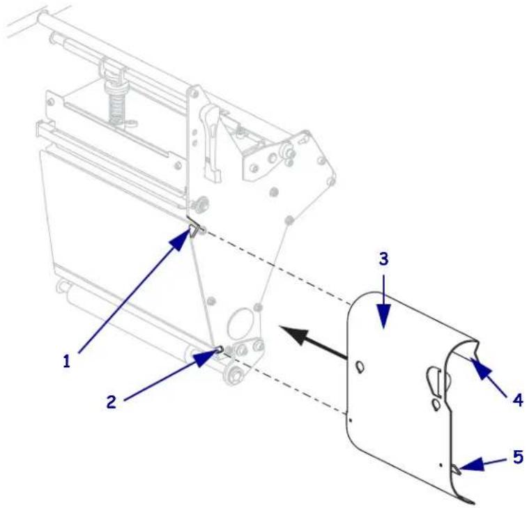
| 1 | Upper slot |
| 2 | Lower slot |
| 3 | Rewind plate |
| 4 | Lip |
| 5 | Adjustable hook plate |
- Insert the hook plate lip 1/2 in. (13 mm) into the lower slot in the side plate.
- Align the upper end of the rewind plate with the matching upper slot in the side plate.
- Slide in the rewind plate until it stops against the printer's main frame.
-
Set the printer to Rewind mode. See Select Print Mode on page 93 for instructions.
-
Insert media into the printer. See Prepare the Media for Loading on page 39 for instructions.
-
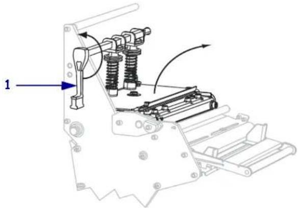
Open the printhead assembly by rotating the printhead-open lever (1) counter-clockwise.
natural_image
Mechanical assembly diagram showing spring-loaded components and a numbered label (1), no readable text or symbols present.- Loosen the thumb screw (not visible from this angle) that is located on the bottom of the outer media guide (1).
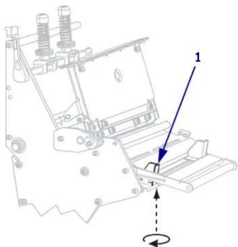
- Slide the outer media guide (1) all the way out.
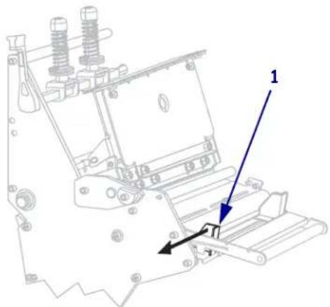
natural_image
Technical line drawing of a mechanical assembly with no visible text or symbols
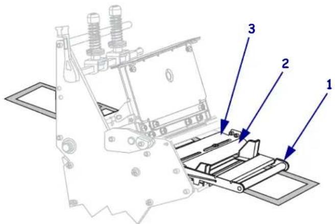
- If your printer includes a media dancer assembly (1), thread the media under the media dancer assembly roller. For all printers, thread the media under the media guide roller (2) and then the upper media sensor (3).
Important • Make sure that you thread the media under these components. If you thread the media over the them, the media obstructs the ribbon sensor and causes a false RIBBON OUT error.
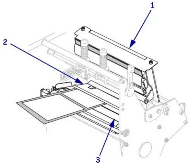
- Push the media forward until it passes under the printhead assembly (1), under the snap plate (2), and then over the platen roller (3).
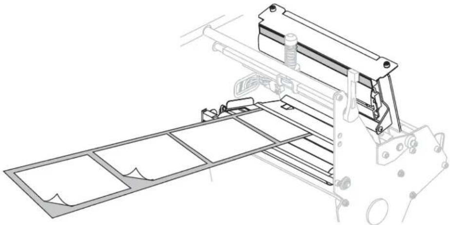
- Extend approximately 36 in. (920 mm) of media out of the printer. Remove and discard the labels from this exposed media.
natural_image
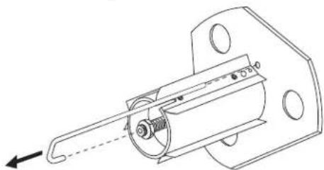
Technical line drawing of a mechanical assembly with frame and mounting bracket (no text or symbols)- Remove the hook from the rewind spindle.
natural_image
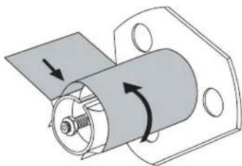
Technical line drawing of a mechanical assembly with no visible text or symbols- If you are using a core, slide it onto the rewind spindle until it is flush against the guide plate.

Note • A core is not required.
- Wind the media liner counterclockwise around the rewind spindle.
natural_image
Mechanical assembly diagram showing a cylindrical component with rotating arrows indicating motion (no text or symbols)- Reinstall the hook. Insert the short end of the hook into the hole in the center of the adjusting nut (1). Insert the long end of the hook into the small hole on the guide plate (2).
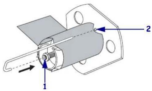
- Rotate the spindle counterclockwise several turns to wind the media liner over the hook and remove any slack.

natural_image
Mechanical assembly diagram showing a rotating cylindrical component mounted on a flanged bracket (no text or symbols)- Align the media with the inner media guide (1). Slide in the outer media guide (2) until it just touches the edge of the media.
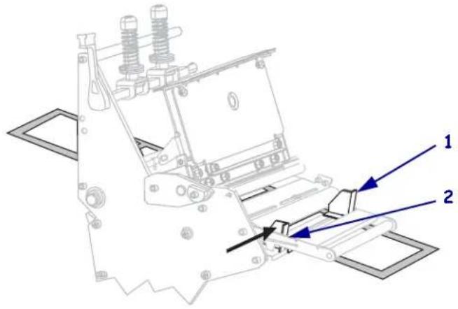
- Tighten the thumb screw (not visible from this angle) that is located on the bottom of the outer media guide (1).
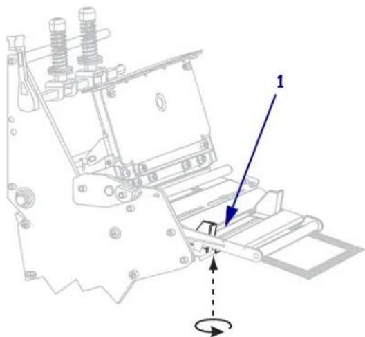
natural_image
Technical line drawing of a mechanical assembly with no visible text or symbols- Push down the printhead assembly (1), and then rotate the printhead-open lever (2) clockwise until it locks into place.
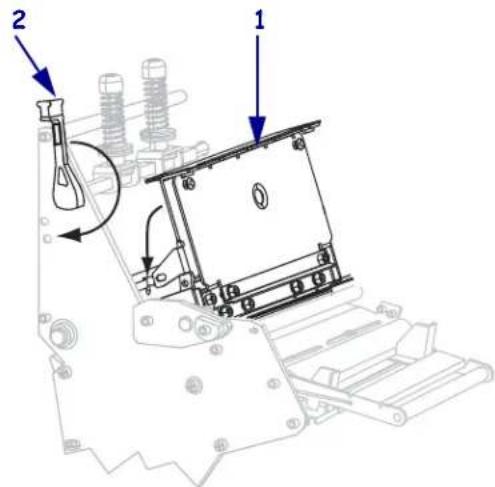
The labels wind on the rewind spindle or core.
Remove Media Liner from the Rewind Spindle
Rewind mode uses the rewind spindle to wind media, while Peel-Off mode uses the rewind spindle to wind used liner. Remove the media or the liner from the rewind spindle each time that you change media.

Important • It is not necessary to turn off the power to remove media or liner from the rewind spindle. If power is turned off, all label formats and images, as well as any temporarily saved parameter settings stored in the printer's internal memory, are lost. When power is turned back on, these items must be reloaded.
To remove media or liner from the rewind spindle, complete these steps:
- Has the media run out?
| If... Then... | |
| No | a. Create slack in the media or liner by rotating the rewind spindle slightly clockwise.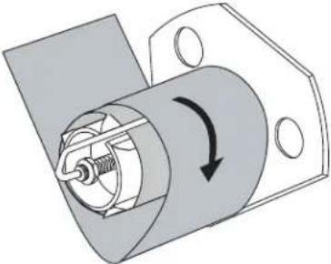 b. Cut or tear the media or liner at the rewind spindle. b. Cut or tear the media or liner at the rewind spindle.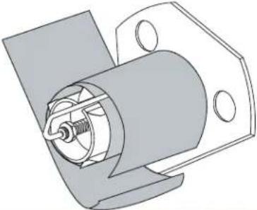 |
| YesContinue | with the next step. |
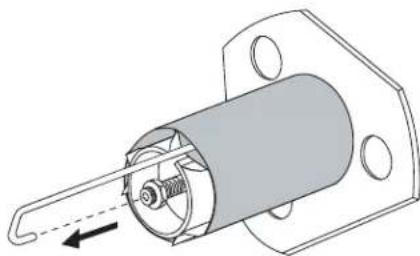
- Pull out the spindle hook.
natural_image
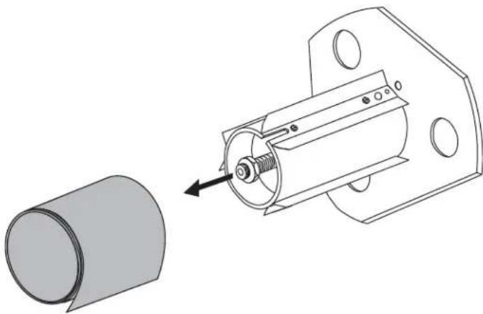
Technical illustration of a mechanical component with internal structure and mounting holes (no text or symbols)- Slide the media or liner off of the rewind spindle.
natural_image
Technical line drawing of a mechanical assembly with a cylindrical component and a cylindrical housing (no text or symbols)Load Ribbon
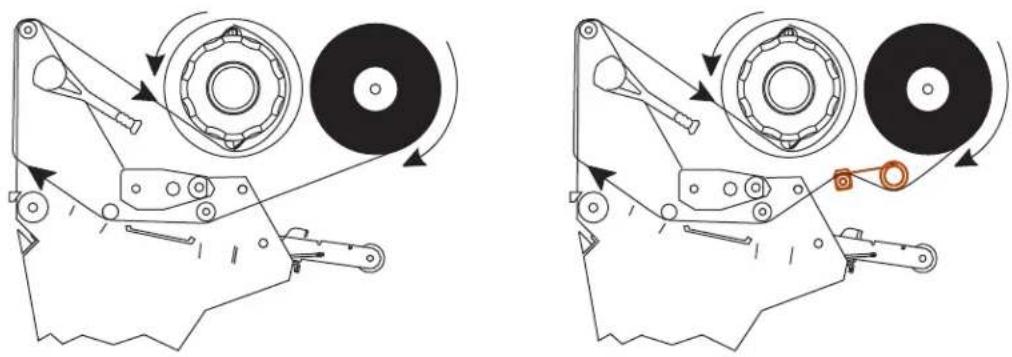
Use the instructions in this section to load ribbon for use with thermal transfer labels. For direct thermal labels, do not load ribbon in the printer. The ribbon path is slightly different for printers with ribbon dancers (Figure 11).

Important • Use ribbon that is wider than the media to protect the printhead from wear. Ribbon must be coated on the outside.
Figure 11 · Ribbon Path
Without Ribbon Dancer With Ribbon Dancer
natural_image
Mechanical assembly diagrams showing two configurations of a gear and pulley mechanism (no text or labels)Caution • While performing any tasks near an open printhead, remove all rings, watches, hanging necklaces, identification badges, or other metallic objects that could touch the printhead. You are not required to turn off the printer power when working near an open printhead, but Zebra recommends it as a precaution. If you turn off the power, you will lose all temporary settings, such as label formats, and you must reload them before you resume printing.
To load ribbon, complete these steps:
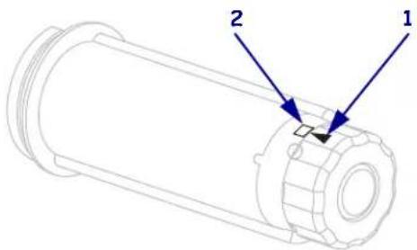
- Align the arrow (1) on the ribbon take-up spindle knob with the notch (2) in the ribbon take-up spindle.
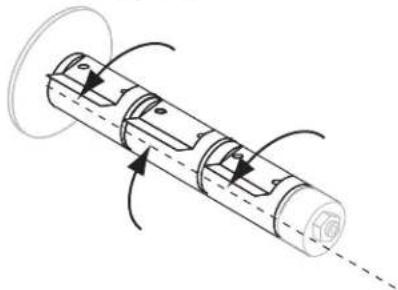
- Align the segments of the ribbon supply spindle.
natural_image
Diagram of a cylindrical mechanical component with internal channels and directional arrows indicating motion (no text or symbols)- Orient the ribbon with the loose end unrolling clockwise.

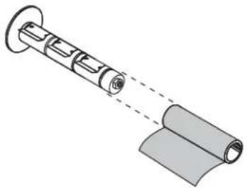
- Place the roll of ribbon on the ribbon supply spindle. Push the roll back as far as it will go.
natural_image
Diagram of a mechanical assembly with cylindrical components and a folded sheet (no text or symbols)- A ribbon leader makes ribbon loading and unloading easier. Does your roll of ribbon have paper or something else attached to the end to serve as a ribbon leader?
| If... Then... | |
| Yes Continue with the next step. | |
| No | a.Tear off a strip of media (labels and liner) about 6–12 in. (150–305 mm) long from the roll.b.Peel a label from the media strip.c.Use this label (1) to attach the end of the ribbon (2) to the media strip (3).The media strip acts as a leader.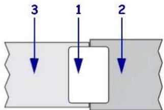 |
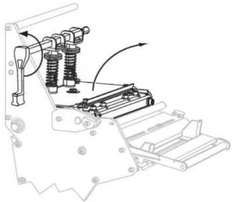
- Open the printhead assembly by rotating the printhead-open lever counter-clockwise.
natural_image
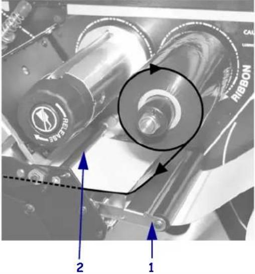
Technical line drawing of a mechanical assembly with springs and rollers (no text or symbols)- Does your printer contain a ribbon dancer assembly? (See Figure 11 on page 68 for the ribbon dancer location.)
| If... Then... | |
| No | Thread the ribbon over the media dancer assembly (1) and under the ribbon guide roller (2). |
 | |
| Yes | a. Thread the ribbon through the ribbon dancer. The ribbon must go under the upper roller (1) and then over the lower roller (2).b. Thread the ribbon under the ribbon guide roller (3).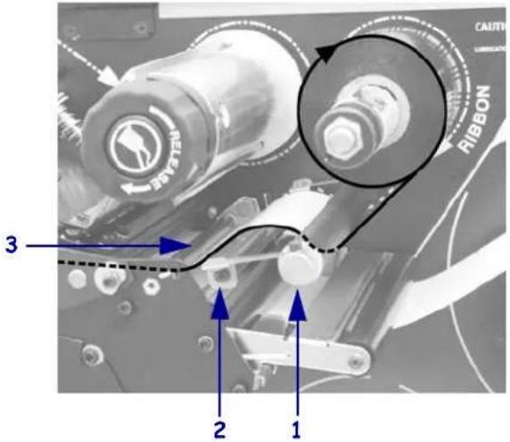 |
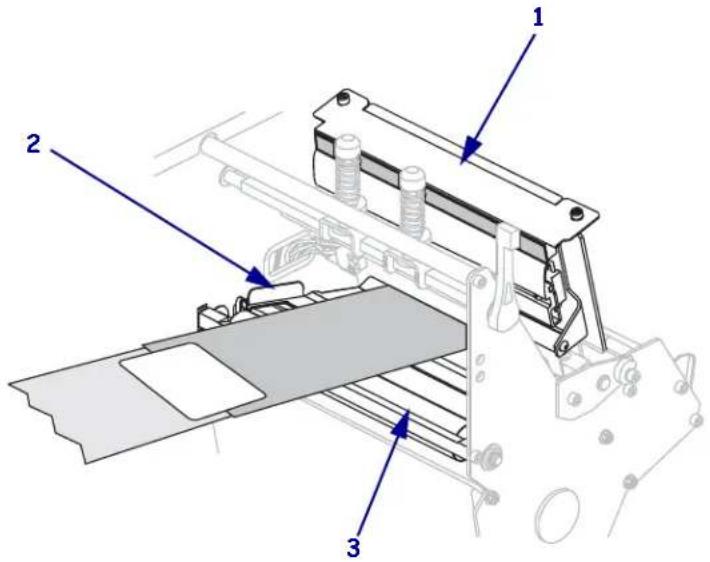
- Push the ribbon leader forward until it passes under the printhead assembly (1), over the snap plate (2), and then over the platen roller (3).
- Bring the ribbon leader over the upper ribbon roller (1) and then toward the ribbon take-up spindle (2).
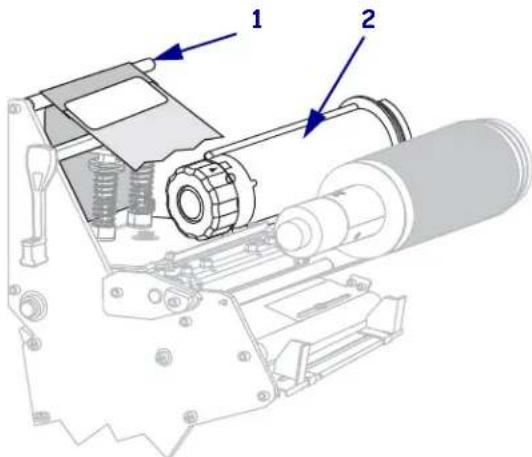
- Wind the ribbon leader and attached ribbon counterclockwise around the ribbon take-up spindle.
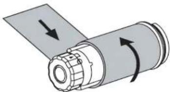
natural_image
Diagram of a mechanical component with directional arrows indicating motion or force (no text or symbols)- Rotate the spindle counterclockwise several turns to wind the ribbon and remove any slack.
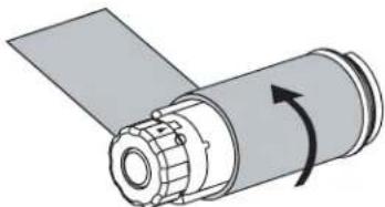
natural_image
Diagram of a mechanical component with a rotating arrow indicating rotation (no text or symbols)- Push down the printhead assembly (1), and then rotate the printhead-open lever (2) clockwise until it locks into place.
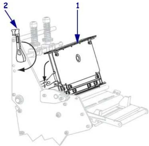
Remove Used Ribbon
Remove used ribbon from the ribbon take-up spindle each time you change the roll of ribbon.
To remove used ribbon, complete these steps:
- Has the ribbon run out?
| If the ribbon... Then | |
| Ran out Continue with the next step. | |
| Did not run out Cut or break the ribbon before the ribbon take-up spindle. | |
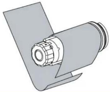 | |
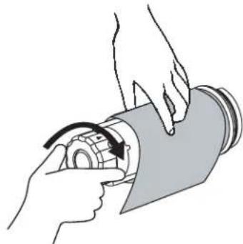
- While holding the ribbon take-up spindle, turn the ribbon release knob clockwise until it stops.
The ribbon release bars pivot down, easing the spindle's grip on the used ribbon.
natural_image
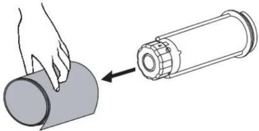
Illustration of hands operating a mechanical device with a rotating arrow (no text or symbols)- Slide the used ribbon off of the ribbon take-up spindle and discard.
natural_image
Illustration of a hand pressing down on a cylindrical component next to a cylindrical device (no text or symbols)Calibrate the Printer
Calibrate the printer when it is first put into service. Calibration allows the printer to establish the proper settings for the specific media and ribbon used in your application. You may calibrate the printer at other times as needed. Table 8 shows the different methods for calibration.
Table 8 • Types of Calibration
| Type of Calibration Description | When/How It Occurs | |
| Auto-calibration The printer | automatically sets the value it detects for the spaces between labels. | Occurs at the following times:When the printer is first turned on if CALIBRATION is selected for MEDIA POWER UP (see Select Media Power-Up Option on page 105).When the printer feeds media after the printhead is closed if CALIBRATION is selected for HEAD CLOSE (see Select Head Close Option on page 106).As part of both the sensor profile and media and ribbon sensor calibration procedures. |
| Long (Standard) Calibration | The printer does the following:feeds media and ribbonsets the values it detects for media length, media type (continuous or non-continuous), and print mode (thermal transfer or direct thermal)updates the sensor values | To perform a long calibration, do one of the following:Press PAUSE on the control panel to pause the printer, and then press CALIBRATE.Select CALIBRATION for the MEDIA POWER UP or HEAD CLOSE parameter (see Select Media Power-Up Option on page 105 or Select Head Close Option on page 106). |
| Short Calibration The printer | calibrates using the current sensor values rather than detecting the spaces between labels and resetting the sensors. This calibration sequence uses fewer labels than the long calibration sequence, but it is less reliable because the values that are stored in the sensors could be incorrect. | Select SHORT CAL for the MEDIA POWER UP or HEAD CLOSE parameter (see Select Media Power-Up Option on page 105 or Select Head Close Option on page 106. |
| Sensor Profile Calibration | The printer auto-calibrates and prints a media sensor profile. | Select the SENSOR PROFILE option on the control panel. See Print Sensor Profile on page 100 for instructions. |
| Media and Ribbon Sensor Sensitivity Calibration | One of the most common adjustments to printer settings. The printer resets the sensitivity of the sensors to detect correctly the media and ribbon that you are using. If you change the type of ribbon and/or media, you might need to reset the sensitivity of the media and ribbon sensors. When the sensors are at their new sensitivity, the printer performs an auto-calibration. | Select the MEDIA AND RIBBON CALIBRATE option on the control panel. See Calibrate Media and Ribbon Sensor Sensitivity on page 101 for instructions. |
Adjust Transmissive Media Sensors
The transmissive media sensor assembly consists of two parts: a light source and a light sensor. The lower media sensor is the light source, and the upper media sensor is the light sensor. The media passes between the two parts.
Adjust these sensors only when the printer cannot detect the top of the labels. In this situation, the control panel LCD displays ERROR CONDITION PAPER OUT, even though there are labels loaded in the printer. For non-continuous media with a notch or hole in the media, the sensor must be directly above the notch or hole.
Upper Media Sensor
For the 220Xi4 The upper media sensor can be positioned along the inner portion of the media (the side closest to the back frame of the printer).
For all other Xi4 models The upper media sensor can be positioned along the inner portion of the media (the side closest to the back frame of the printer) or the outer portion of the media (the side farthest from the back frame of the printer). Moving the media sensor to the outer portion of the media should be performed only by a qualified service technician.
To reposition the upper media sensor along the inside portion of the media, complete these steps:
- Remove the ribbon (if ribbon is used).
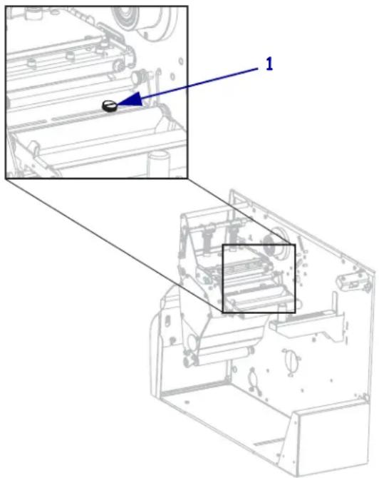
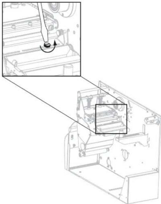
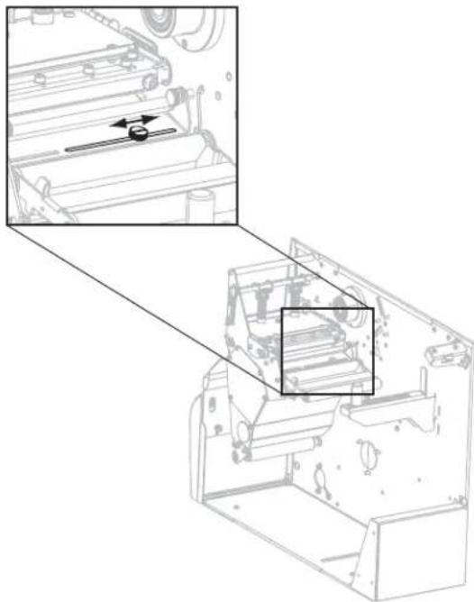
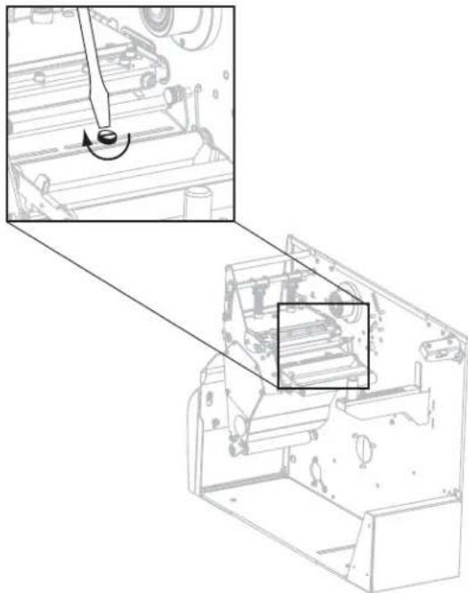
- Locate the upper media sensor adjustment screw (1). The upper media sensor eye is directly below the adjustment screw head.
natural_image
Technical diagram of a mechanical assembly with labeled component 1, showing internal components and part outline (no text or symbols beyond labels)- Using a thin, flat-blade screwdriver, loosen the upper media sensor adjustment screw.
natural_image
Technical line drawing of a mechanical assembly with an inset showing a tool interacting with a component (no text or symbols present)- Slide the upper media sensor along the slot to the desired position.
natural_image
Technical line drawing of a mechanical assembly with internal components and a magnified inset showing a component detail (no text or symbols)- Tighten the adjustment screw to secure the upper media sensor in its new position.
natural_image
Technical line drawing of a mechanical assembly with an inset showing a tool interacting with a component (no text or symbols present)- Adjust the lower media sensor to match the new position of the upper media sensor. See Lower Media Sensor on page 80.
Lower Media Sensor
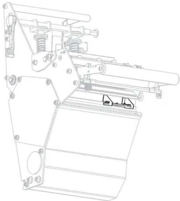
After you adjust the upper media sensor, adjust the lower media sensor to match its new position.
To adjust the lower media sensor, complete these steps:
- Locate the lower media sensor assembly under the rear roller. The sensor is a spring clip holding a circuit board.
natural_image
Technical line drawing of a mechanical device with no visible text or symbols- Slide the lower sensor until it is under the upper media sensor. Use the light that shines from the lower sensor to help align it with the upper sensor. Gently pull the wires as needed (wires should have a little slack).
Adjust Printhead Pressure and Toggle Position
Print quality depends on the labels and ribbon used as well as the toggle pressure and position. Make sure that your labels and ribbon are acceptable for your application. If they are, check the toggle position and then the printhead pressure.
Toggle Position Adjustment
You may need to adjust the toggles if printing is too light on one side or if thick labels are used. If the toggle pressure is too light or uneven, the labels and ribbon may slip.
To position the toggles, complete these steps:
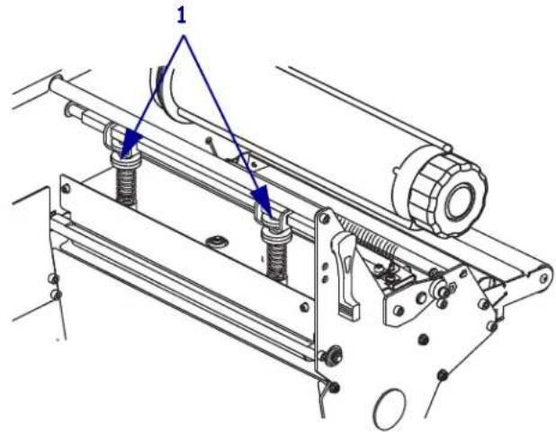
- Loosen the locking nuts (1) at the top of the toggle assemblies.
-
Slide the toggles until they provide even pressure on the media. For extremely narrow media, position one toggle over the center of the labels, and decrease the pressure on the unused toggle.
-
Tighten the locking nuts.
Printhead Pressure Adjustment
If positioning the toggles properly does not solve a print quality problem, try adjusting the printhead pressure. Maximize printhead life by using the lowest pressure that produces the desired print quality.

Caution • Observe proper electrostatic safety precautions when handling any static-sensitive components such as circuit boards and printheads.
To adjust printhead pressure, complete these steps:
- Print some labels at 2.4 in. (61 mm) per second by running the PAUSE Self Test on page 148.
- While printing labels, use the control panel controls to lower the darkness setting until the labels are printing gray instead of black.
- Loosen the upper knurled nuts on the toggle assemblies (1).
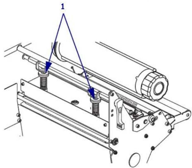
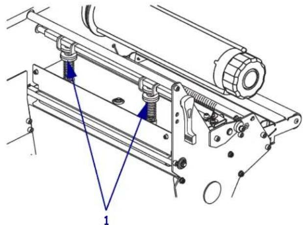
- Some media types require higher pressure to print well. For these media types, increase or decrease pressure using the lower knurled nuts (1) until the left and right edges of the printed area are equally dark.
natural_image
Technical line drawing of a mechanical assembly with no visible text or symbols-
Using the control panel, increase the darkness to the desired level.
-
Tighten the upper knurled nuts.

Notes •
4
Configuration

natural_image
Abstract black and white pattern with curved white and black shapes (no text or symbols)This section describes the control panel parameters that are used to configure the printer for operation.
Contents
Setup Mode 86
Enter and Use Setup Mode 86
Exit Setup Mode....87
Change Password-Protected Parameters 88
Default Password Value....88
Disable the Password Protection Feature 88
Print a Configuration Label....89
Print a Network Configuration Label 90
Standard Control Panel Parameters 91
Additional Control Panel Parameters.... 113
Setup Mode
After you have installed the media and ribbon and the Power-On Self Test (POST) is complete, the control panel displays PRINTER READY. You may now set printer parameters for your application using the control panel display and the buttons directly below it. If it becomes necessary to restore the initial printer defaults, see FEED and PAUSE Self Test on page 152.

Important • Certain printing conditions may require that you adjust printing parameters, such as print speed, darkness, or print mode. These conditions include (but are not limited to):
- printing at high speeds
- peeling the media
- the use of extremely thin, small, synthetic, or coated labels
Because these and other factors affect print quality, run tests to determine the best combination of printer settings and media for your application. A poor match may limit print quality or print rate, or the printer may not function properly in the desired print mode.

Note • If the printer is operating on an IP network and you have a ZebraNet 10/100 Print Server or Wireless Plus Print Server, you can change the printer's parameters in these additional ways:
- with ZebraLink™ WebView. For information, see the appropriate print server user guide.
- with ZebraNet Bridge. For information, see the ZebraNet Bridge Enterprise Printer Management User Guide.
Enter and Use Setup Mode
Use the LCD on the control panel to view and adjust printer settings through Setup mode. When a parameter is changed, an asterisk (*) appears in the upper left corner of the display to indicate that the value is different from the one currently active in the printer.
| Press this key... To do the following... | |
| SETUP/EXIT enter or exit Setup mode. | |
| SELECT select or deselect a parameter. | |
| PLUS (+) continue to the next parameter. | |
| MINUS (-) return to the previous parameter in the cycle. |
Exit Setup Mode
When you exit setup mode, you have several options for saving, changing, or not changing parameters.
To leave Setup mode, complete these steps:
- Press SETUP/EXIT.
The LCD displays SAVE CHANGES.
- Press PLUS (+) or MINUS (-) to display the save options:
| LCD Description | |
| PERMANENT | Stores values in the printer even when power is turned off. |
| TEMPORARY | Saves the changes until power is turned off. |
| CANCEL | Cancels all changes made since you entered Setup mode, except for changes made to the darkness and tear-off settings, which go into effect as soon as they are made. |
| LOAD DEFAULTS | Restores all parameters other than the network settings back to the factory defaults. Use care when loading defaults because you will need to reload all settings that you changed manually.Note • On non-RFID printers, loading factory defaults causes the printer to auto-calibrate. |
| LOAD LAST SAVE | Loads values from the last permanent save. |
| DEFAULT NET | Restores the wired and wireless network settings back to factory defaults. |
- Press NEXT/SAVE to select the displayed choice.
When the configuration and calibration sequence is done, PRINTER READY displays.
Change Password-Protected Parameters
Certain parameters, including the communication parameters, are password-protected by factory default.
Caution • Do not change password-protected parameters unless you have a complete understanding of the parameters' functions. If the parameters are set incorrectly, the printer may function unpredictably.
The first time that you attempt to change a password-protected parameter, the printer displays ENTER PASSWORD. Before you can change the parameter, you must enter the four-digit numeric password. After you have entered the password correctly, you do not have to enter it again unless you leave Setup mode by pressing SETUP/EXIT or by turning off (O) the printer.
To enter a password for a password-protected parameter, complete these steps:
- At the password prompt, use MINUS (-) to change the selected digit position.
- When you have selected the digit that you wish to change, use PLUS (+) to increase the selected digit value. Repeat these two steps for each digit of the password.
- After entering the password, press NEXT/SAVE.
The parameter you selected to change is displayed. If the password was entered correctly, you can change the value.
Default Password Value
The default password value is 1234. The password can be changed using the Zebra Programming Language (ZPL) command ^KP (Define Password) or using the printer's web pages (ZebraNet® 10/100 Print Server or Wireless Plus Print Server required).
Disable the Password Protection Feature
You can disable the password protection feature so that it no longer prompts you for a password by setting the password to 0000 via the ^KP ZPL command. To re-enable the password-protection feature, send the ZPL command ^KPx, where x can be any number from 1 to 9999.
Print a Configuration Label
A configuration label lists the printer settings that are stored in configuration memory. After you load the media and ribbon (if necessary), print a configuration label as a record of your printer's current settings. Keep the label to use when troubleshooting printing problems.
To print a configuration label, complete these steps:
- On the control panel, press SETUP/EXIT.
- Press NEXT/SAVE or PREVIOUS to scroll through the parameters until you reach LIST SETUP.
- Press PLUS (+) to confirm printing.
A configuration label prints (Figure 12).
Figure 12 • Sample Configuration Label
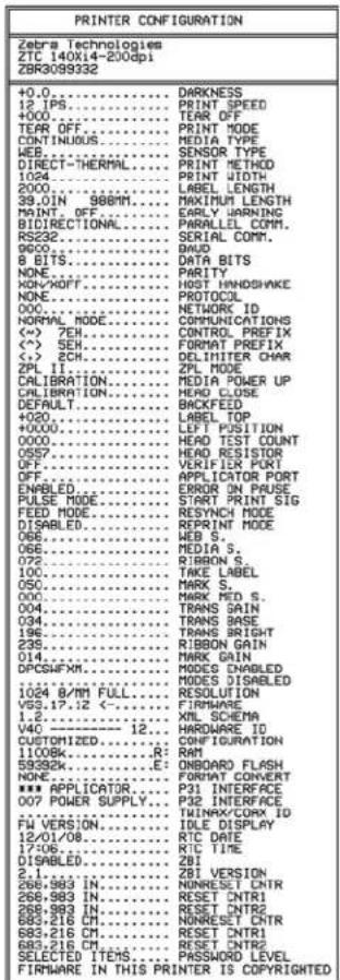
Print a Network Configuration Label
If you are using a print server, you can print a network configuration label after the printer is connected to the network.
To print a network configuration label, complete these steps:
-
On the control panel, press SETUP/EXIT.
-
Press NEXT/SAVE or PREVIOUS to scroll through the parameters until you reach LIST NETWORK.
-
Press PLUS (+) to confirm printing.
A network configuration label prints (Figure 13). An asterisk designates whether the wired or wireless print server is active. If no wireless print server is installed, the wireless portion of the label does not print.
Figure 13 · Network Configuration Label (with a Wireless Print Server installed)

FIRMWARE IN THIS PRINTER IS COPYRIGHTED
Standard Control Panel Parameters
Table 9 shows parameters in the order in which they are displayed when you press NEXT/SAVE after entering Setup mode. For parameters that do not appear in this table, see Additional Control Panel Parameters on page 113.

Note • Your label preparation software or the printer driver may override adjustments made through the control panel. Refer to the software or driver documentation for more information.
Table 9 · Printer Parameters (Sheet 1 of 22)
| Language/Parameter | Action/Explanation |
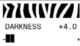 | Adjust Print DarknessDarkness (burn duration) settings depend on a variety of factors, including ribbon type, media type, and the condition of the printhead. You may adjust the darkness for consistent high-quality printing.Important• Set the darkness to the lowest setting that provides good print quality. If the darkness is set too high, the ink may smear, the ribbon may burn through, or the printhead may wear prematurely.If printing is too light or if there are voids in printed areas, increase the darkness. If printing is too dark or if there is spreading or bleeding of printed areas, decrease the darkness.TheFEED Self Test on page 149can be used to determine the best darkness setting. You may want to adjust darkness while performing thePAUSE Self Test on page 148. Because the darkness setting takes effect immediately, you can see the results on labels that are currently printing. Darkness settings also may be changed by the driver or software settings.Default Value: +4.0Range: 0 to +30.0To change the value shown:1. Press PLUS (+) to increase darkness.2. Press MINUS (-) to decrease darkness. |
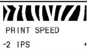 | Adjust Print SpeedAdjusts the speed for printing a label (given in inches per second). Slower print speeds typically yield better print quality. Print speed changes take effect upon exiting Setup mode.Default Value: 2 IPSRange: Varies by printer type (seePrint Specifications by Model on page 159for values by model)To change the value shown:1. Press PLUS (+) to increase the value.2. Press MINUS (-) to decrease the value. |
Table 9 · Printer Parameters (Sheet 2 of 22)
| Language/Parameter | Action/Explanation | |
Adjust the Tear-Off PositionThis parameter establishes the position of the media over the tear-off/peel-off bar after printing.See Figure 14. Higher numbers move the media out (the tear line moves closer to the leading edge of the next label), and lower numbers move the media in (the tear line moves closer to the edge of the label just printed).Figure 14 • Tear-Off Position Adjustment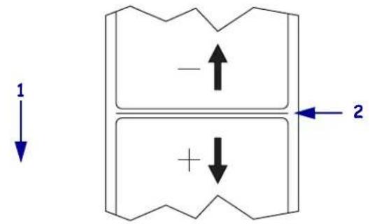 Default Value: 0Range: -120 to +120To change the value shown:Press PLUS (+) to increase the value. Each press adjusts the tear-off position by four dot rows.Press MINUS (-) to decrease the value. Each press adjusts the tear-off position by four dot rows. Default Value: 0Range: -120 to +120To change the value shown:Press PLUS (+) to increase the value. Each press adjusts the tear-off position by four dot rows.Press MINUS (-) to decrease the value. Each press adjusts the tear-off position by four dot rows. | ||
Table 9 · Printer Parameters (Sheet 3 of 22)
| Language/Parameter | Action/Explanation |
 PRINT MODE-TEAR OFF + PRINT MODE-TEAR OFF + | Select Print ModeThis parameter tells the printer how printed labels will be removed. Make sure that you select a print mode that is compatible with your printer and printer options. For information about how the print modes work with different printer options, seePrint Modes and Printer Options on page 36.Default Value (non-RFID printers): TEAR-OFFSelections (non-RFID printers): TEAR-OFF, PEEL-OFF, CUTTER, DELAYED CUT, APPLICATOR, REWINDDefault Value (RFID printers): RFID MODESelections (RFID printers): TEAR-OFF, PEEL-OFF, CUTTER, DELAYED CUT, RFID MODE, REWINDNote• RFID MODE appears only on printers that have an RFID reader installed and the correct firmware loaded in the printer. The 110Xi4 is RFID-ready, but it does not come with an RFID reader installed. For more information about purchasing the RFID option for these printers, contact your authorized Zebra reseller.To change the value shown:1. Press PLUS (+) or MINUS (-) to scroll through the options. |
 MEDIA TYPE-NON-CONTINUOUS + MEDIA TYPE-NON-CONTINUOUS + | Set Media TypeThis parameter tells the printer the type of media that you are using (seeTypes of Media on page 31 for more information). Selecting continuous media requires that you include a label length instruction in your label format (^LLxxxx if you are using ZPL or ZPL II).When non-continuous media is selected, the printer feeds media to calculate label length (the distance between two recognized registration points of the inter-label gap, webbing, or alignment notch or hole).Default Value: NON-CONTINUOUSSelections: NON-CONTINUOUS, CONTINUOUSTo change the value shown:1. Press PLUS (+) or MINUS (-) to scroll through the options. |
 SENSOR TYPE-WEB + SENSOR TYPE-WEB + | Set Sensor TypeThis parameter tells the printer whether you are using media with a web (gap/space between labels, notch, or hole) to indicate the separations between labels or if you are using media with a black mark printed on the back. If your media does not have black marks for registration on the back, leave your printer at the default (WEB).Default Value: WEBSelections: WEB, MARKTo change the value shown:1. Press PLUS (+) or MINUS (-) to toggle between the options. |
Table 9 · Printer Parameters (Sheet 4 of 22)
| Language/Parameter | Action/Explanation | ||
 PRINT METHOD-THERMAL-TRANS. + PRINT METHOD-THERMAL-TRANS. + | Select Print MethodThe print method parameter tells the printer the method of printing that you want to use: direct thermal (no ribbon) or thermal transfer (using thermal transfer media and ribbon).Default Value: THERMAL-TRANS.Selection: THERMAL-TRANS., DIRECT THERMALTo change the value shown:1. Press PLUS (+) or MINUS (-) to scroll through the options. | ||
 PRINT WIDTH 2496 PRINT WIDTH 2496 | Set Print WidthThis parameter specifies the printable area across the width of the label.Table 10 shows the ranges and default values for print width, which are based on the printer model and the printhead resolution.Table 10 • Print Width Ranges and Maximum Values | ||
| PrintheadResolution | Printer | ||
| 110Xi4 140Xi4, 170Xi4, 220Xi4 | |||
| 200 dpi | Default Value: 832Range: 2 to 832 dots | Default Value: 1344Range: 2 to 1344 dots | |
| 300 dpi | Default Value: 1248Range: 2 to 1248 dots | Default Value: 1984Range: 2 to 1984 dots | |
| 600 dpi | Default Value: 2496Range: 2 to 2496 dots | N/A | |
| Note • Setting the width too narrow can result in portions of a label format not being printed on the media. Setting the width too wide wastes formatting memory and can cause printing off of the label and on the platen roller. This setting can affect the horizontal position of the label format if the image was inverted using the ^POI ZPL II command.To change the value shown:1. Press PLUS (+) or MINUS (-) to change the value shown. | |||
Table 9 · Printer Parameters (Sheet 5 of 22)
| Language/Parameter | Action/Explanation |
 MAXIMUM LENGTH-39.0IN 988MM MAXIMUM LENGTH-39.0IN 988MM | Set Maximum Label LengthThis parameter is used during the media portion of the calibration process.Always set maximum label length to a value that is at least 1.0 in.(25.4 mm) greater than the actual label length (Figure 15). If the value is set to a smaller value than the label length, the printer assumes that continuous media is loaded, and the printer cannot calibrate.For example, if the label length is 5.0 inches (126 mm) including the interlabel gap, set the parameter for 6.0 inches (152 mm). If the label length is 7.5 inches (190 mm), set the parameter for 9.0 inches (229 mm).Figure 15 • Label Length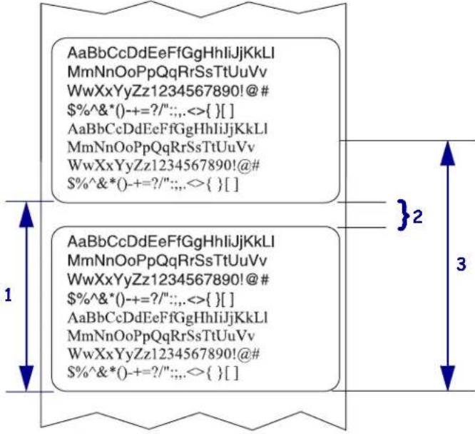 Default Value: 39.0 inches (988 mm)Selections: Values are adjustable in one-inch (25.4 mm) incrementsTo change the value shown:1. Press PLUS (+) or MINUS (-) to change the value shown. Default Value: 39.0 inches (988 mm)Selections: Values are adjustable in one-inch (25.4 mm) incrementsTo change the value shown:1. Press PLUS (+) or MINUS (-) to change the value shown. |
 *SUPPLIES WARNING-D DISABLED + *SUPPLIES WARNING-D DISABLED + | Set Supplies Low WarningWhen this feature is enabled, the printer provides a warning when the media or ribbon level is low.Default: DISABLEDSelections: ENABLED, DISABLED |
Table 9 · Printer Parameters (Sheet 6 of 22)
| Language/Parameter | Action/Explanation |
 *EARLY WARNING-MAINT. OFF + *EARLY WARNING-MAINT. OFF + | Set Early Warning for MaintenanceWhen this feature is enabled, the printer provides warnings when the printhead needs to be cleaned.Default Value: MAINT. OFFSelections: MAINT. OFF, MAINTENANCE ONTo change the Early Warning settings:1. When the LCD displays EARLY WARNING MAINTENANCE, press PLUS (+) or MINUS (-) to toggle between OFF and ON. (If you are prompted for a password, enter your password using the instructions in Change Password-Protected Parameters on page 88.)2. Exit Setup mode and save changes to enable additional parameters related to the early warning system.3. Enter Setup mode again and go to the following parameters to enter the printhead cleaning interval and the printhead life. |
 HEAD CLEANING-150 M 492 FT HEAD CLEANING-150 M 492 FT | Set Printhead Cleaning Interval for Early WarningThis parameter appears only when Early Warning for Maintenance is enabled. This value should correspond to the length of the media or ribbon roll that you are using.Default Value: 450 M/1476 FTSelections: 100 M/328 FT to 450 M/1476 FT in 50 M incrementsTo change the value shown:1. Press PLUS (+) or MINUS (-) to set the printhead cleaning interval to the desired number of inches of media or ribbon.When the printhead reaches the set length, WARNING CLEAN PRINTHEAD appears on the LCD. If the alert function is enabled, the printer generates an alert. |
 HEAD CLEANED?-NO YES+ HEAD CLEANED?-NO YES+ | Reset Printhead Cleaning Counter for Early WarningThis parameter appears only when Early Warning for Maintenance is enabled.To reset the printhead cleaning counter:1. Did you clean the printhead?If you cleaned the printhead, press PLUS (+) to select YES.If you did not clean the printhead, press MINUS (-) to select NO. |
Table 9 · Printer Parameters (Sheet 7 of 22)
| Language/Parameter | Action/Explanation |
 HEAD LIFE- 1000000 IN + HEAD LIFE- 1000000 IN + | Set Printhead Life for Early WarningThis parameter appears only when Early Warning for Maintenance is enabled. Set this value to the number of inches of media that the printhead is expected to print.Default Value: 1,000,000 inchesRange: 100 to 1,000,000 inchesTo change the value shown:1. Press MINUS (-) to move the cursor.2. Press PLUS (+) to increase the value of the digit.When the printhead reaches the set length, WARNING REPLACE HEAD appears on the LCD. If the alert function is enabled, the printer generates an alert. |
 NEW PRINTHEAD?-NO YES+ NEW PRINTHEAD?-NO YES+ | Reset Printhead Life Counter for Early WarningThis parameter appears only when Early Warning for Maintenance is enabled.To reset the printhead life counter:1. Did you replace the printhead?If you replaced the printhead, press PLUS (+) to select YES.If you did not replace the printhead, press MINUS (-) to select NO. |
 NONRESET CNTRO IN NONRESET CNTRO IN | View Non-Resettable CounterThis parameter displays the total length of media that the printer has printed. You can use ZPL commands to change the unit of measure for this counter. For the commands, refer to the ZPL Programming Guide. |
 RESET CNTR1O IN RESET CNTR1O IN | View User-Controlled Counter 1This parameter displays the total length of media that the printer has printed since this parameter was last reset. You can use ZPL commands to change the unit of measure and reset this counter. For the commands, refer to the ZPL Programming Guide. |
 RESET CNTR2O IN RESET CNTR2O IN | View User-Controlled Counter 2This parameter displays the total length of media that the printer has printed since this parameter was last reset. You can use ZPL commands to change the unit of measure and reset this counter. For the commands, refer to the ZPL Programming Guide. |
Table 9 · Printer Parameters (Sheet 8 of 22)
| Language/Parameter | Action/Explanation |
 PRINT METERSPRINT+ PRINT METERSPRINT+ | Print Counter ReadingsPrints a label that lists the odometer readings for the following:the non-resettable counterthe two user-controlled countersthe Early Warning for Maintenance counters, which indicate when the printhead was last cleaned and the printhead lifeIf the Early Warning for Maintenance feature is disabled, the counters related to it do not print.To print a list of the odometer readings:1. Press PLUS (+) to print the odometer readings. |
 LIST FONTSPRINT+ LIST FONTSPRINT+ | List FontsThis option prints a label that lists the available fonts in the printer, including standard printer fonts plus any optional fonts. Fonts may be stored in RAM or Flash memory.To print a list of the available fonts:1. Press PLUS (+) to select PRINT. |
 LIST BAR CODESPRINT+ LIST BAR CODESPRINT+ | List Bar CodesThis option prints a label that lists the available bar codes in the printer. Bar codes may be stored in RAM or Flash memory.To print a list of the available bar codes:1. Press PLUS (+) to select PRINT. |
 LIST IMAGESPRINT+ LIST IMAGESPRINT+ | List ImagesThis option prints a label that lists the available images stored in the printer's RAM, Flash memory, or optional memory card.To print a list of the available images:1. Press PLUS (+) to select PRINT. |
 LIST FORMATSPRINT+ LIST FORMATSPRINT+ | List FormatsThis option prints a label that lists the available formats stored in the printer's RAM, Flash memory, or optional memory card.To print a list of the available formats:1. Press PLUS (+) to select PRINT. |
 LIST SETUPPRINT+ LIST SETUPPRINT+ | List SetupThis option prints a configuration label (see Figure 12 on page 89), which lists the current printer configuration.To print a configuration label:1. Press PLUS (+) to select PRINT. |
Table 9 · Printer Parameters (Sheet 9 of 22)
| Language/Parameter | Action/Explanation |
 LIST NETWORKPRINT+ LIST NETWORKPRINT+ | List Network SettingsThis option prints a network configuration label (see Figure 13 on page 90), which lists the settings for any print server that is installed.To print a network configuration label:1. Press PLUS (+) to select PRINT. |
 LIST ALLPRINT+ LIST ALLPRINT+ | List AllThis option prints labels that list the available fonts, bar codes, images, formats, and the current printer and network configurations.To print labels for all settings:1. Press PLUS (+) to select PRINT. |
 INIT FLASH MEM.YES+ INIT FLASH MEM.YES+ | Initialize Flash MemoryThis option erases all previously stored information from Flash memory.Caution • This option completely erases the Flash memory.To initialize Flash memory:1. If prompted for a password, enter the printer password. For instructions, see Change Password-Protected Parameters on page 88.The display shows INITIALIZE FLASH?2. Press PLUS (+) to select YES.The display shows ARE YOU SURE?.3. Do you want to continue?Press MINUS (-) to select NO to cancel the request and return to the INITIALIZE FLASH prompt.Press PLUS (+) to select YES and begin initialization.When initialization is complete, the control panel displays INITIALIZING COMPLETED.Note • Depending on the amount of free FLASH memory, initialization may take up to 1 minute to complete. initialization may take up to 1 minute to complete. |
Table 9 · Printer Parameters (Sheet 10 of 22)
| Language/Parameter | Action/Explanation |
 SENSOR PROFILEPRINT+ SENSOR PROFILEPRINT+ | Print Sensor ProfileA sensor profile shows sensor settings compared to actual sensor readings.This label (which will extend across several actual labels or tags) can be used to troubleshoot printing problems. To interpret the results of the sensor profile, seeSensor Profileon page 154.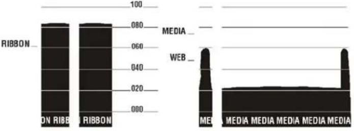 To print a sensor profile:Press PLUS (+) to start this standard calibration procedure and print a media sensor profile.If the sensitivity of the sensors must be adjusted, performCalibrate Media and Ribbon Sensor Sensitivity on page 101. To print a sensor profile:Press PLUS (+) to start this standard calibration procedure and print a media sensor profile.If the sensitivity of the sensors must be adjusted, performCalibrate Media and Ribbon Sensor Sensitivity on page 101. |
Table 9 • Printer Parameters (Sheet 11 of 22)
| Language/Parameter | Action/Explanation |
 MEDIA AND RIBBONCALIBRATE+ MEDIA AND RIBBONCALIBRATE+ | Calibrate Media and Ribbon Sensor SensitivityUse this procedure to adjust sensitivity of media and ribbon sensors. Important·Follow this procedure exactly as presented. All of the steps must be performed even if only one of the sensors requires adjustment. You may press MINUS (-) at any step in this procedure to cancel the process.To perform a media and ribbon sensor calibration:1. Press PLUS (+) to start the calibration procedure.The LOAD BACKING prompt displays.2. Open the printhead.3. Remove approximately 8 in. (203 mm) of labels from the backing, and pull the media into the printer so that only the backing is between the media sensors.4. Leave the printhead open.5. Press PLUS (+) to continue.The REMOVE RIBBON prompt displays.6. Remove the ribbon (if used).7. Close the printhead.8. Press PLUS (+) to continue.The message CALIBRATING PLEASE WAIT displays.The printer adjusts the scale (gain) of the signals that it receives from the media and ribbon sensors based on the specific media and ribbon combination being used. On the sensor profile, this essentially corresponds to moving the peak of the graph up or down to optimize the readings for your application.When calibration is complete,RELOAD ALL displays.9. Open the printhead and pull the media forward until a label is positioned under the media sensor.10. Reload the ribbon (if used).11. Close the printhead.12. Press PLUS (+) to continue.The printer performs an auto-calibration. During this process, the printer checks the readings for the media and ribbon based on the new scale established, determines the label length, and determines the print mode. To see the new readings on the new scale, print a sensor profile. Important·Follow this procedure exactly as presented. All of the steps must be performed even if only one of the sensors requires adjustment. You may press MINUS (-) at any step in this procedure to cancel the process.To perform a media and ribbon sensor calibration:1. Press PLUS (+) to start the calibration procedure.The LOAD BACKING prompt displays.2. Open the printhead.3. Remove approximately 8 in. (203 mm) of labels from the backing, and pull the media into the printer so that only the backing is between the media sensors.4. Leave the printhead open.5. Press PLUS (+) to continue.The REMOVE RIBBON prompt displays.6. Remove the ribbon (if used).7. Close the printhead.8. Press PLUS (+) to continue.The message CALIBRATING PLEASE WAIT displays.The printer adjusts the scale (gain) of the signals that it receives from the media and ribbon sensors based on the specific media and ribbon combination being used. On the sensor profile, this essentially corresponds to moving the peak of the graph up or down to optimize the readings for your application.When calibration is complete,RELOAD ALL displays.9. Open the printhead and pull the media forward until a label is positioned under the media sensor.10. Reload the ribbon (if used).11. Close the printhead.12. Press PLUS (+) to continue.The printer performs an auto-calibration. During this process, the printer checks the readings for the media and ribbon based on the new scale established, determines the label length, and determines the print mode. To see the new readings on the new scale, print a sensor profile. |
 PARALLEL COMM.-B IDIRECTIONAL + PARALLEL COMM.-B IDIRECTIONAL + | Set Parallel CommunicationsSelect the communications port that matches the one being used by the host computer.Default Value:BIDIRECTIONALSelections:BIDIRECTIONAL, TWINAX/COAX, UNIDIRECTIONALTo change the value shown:1. Press PLUS (+) or MINUS (-) to scroll through the options. |
Table 9 • Printer Parameters (Sheet 12 of 22)
| Language/Parameter | Action/Explanation |
 SERIAL COMM.-RS232+ SERIAL COMM.-RS232+ | Set Serial CommunicationsSelect the communications port that matches the one being used by the host computer. This setting applies only when the serial port is used. Note·Select RS232 if you are using an external adapter to enable RS422/485 operation.Default Value: RS232Selections: RS232, RS422/485, RS485 MULTIDROPTo change the value shown:1. Press PLUS (+) or MINUS (-) to scroll through the options. Note·Select RS232 if you are using an external adapter to enable RS422/485 operation.Default Value: RS232Selections: RS232, RS422/485, RS485 MULTIDROPTo change the value shown:1. Press PLUS (+) or MINUS (-) to scroll through the options. |
 BAUD-9600+ BAUD-9600+ | Set BaudThis setting applies only when the serial port is used. The baud setting of the printer must match the baud setting of the host computer for accurate communications to take place. Select the value that matches the one being used by the host computer.Default Value: 9600Selections: 300, 600, 1200, 2400, 4800, 9600, 14400, 19200, 28800, 38400, 57600, 115200To change the value shown:1. Press PLUS (+) or MINUS (-) to scroll through the options. |
 DATA BITS-8 BITS DATA BITS-8 BITS | Set Data BitsThis setting applies only when the serial port is used. The data bits of the printer must match the data bits of the host computer for accurate communications to take place. Set the data bits to match the setting being used by the host computer.Default Value: 8 BITSSelections: 7 BITS, 8 BITSTo change the value shown:1. Press PLUS (+) or MINUS (-) to toggle between the options. |
 PARITY-NONE+ PARITY-NONE+ | Set ParityThis setting applies only when the serial port is used. The parity of the printer must match the parity of the host computer for accurate communications to take place. Select the parity that matches the one being used by the host computer.Default Value: NONESelections: EVEN, ODD, NONETO change the value shown:1. Press PLUS (+) or MINUS (-) to scroll through the options. |
Table 9 · Printer Parameters (Sheet 13 of 22)
| Language/Parameter | Action/Explanation |
 HOST HANDSHAKE-XON/XOFF + HOST HANDSHAKE-XON/XOFF + | Set Host HandshakeThis setting applies only when the serial port is used. The handshake protocol of the printer must match the handshake protocol of the host computer for communication to take place. Select the handshake protocol that matches the one being used by the host computer.Default Value: XON/XOFFSelections: XON/XOFF, DSR/DTR, RTS/CTSTo change the value shown:1. Press PLUS (+) or MINUS (-) to scroll through the options. |
 PROTOCOL-NONE + PROTOCOL-NONE + | Set ProtocolProtocol is a type of error checking system. Depending on the selection, an indicator may be sent from the printer to the host computer signifying that data has been received. Select the protocol that is requested by the host computer. Further details on protocol can be found in the ZPL Programming Guide.Default Value: NONESelections: NONE, ZEBRA, ACK_NAKNote • ZEBRA is the same as ACK_NAK, except that ZEBRA  response messages are sequenced. If ZEBRA is selected, the printer must use DSR/DTR for host handshake protocol.To change the value shown:1. Press PLUS (+) or MINUS (-) to scroll through the options. response messages are sequenced. If ZEBRA is selected, the printer must use DSR/DTR for host handshake protocol.To change the value shown:1. Press PLUS (+) or MINUS (-) to scroll through the options. |
 NETWORK ID- 000 + NETWORK ID- 000 + | Set Network IDThis parameter assigns a unique number to the printer when the printer is operating in an RS422/485 multi-drop network environment (an external RS422/485 adapter is required). This gives the host computer the means to address a specific printer. This does not affect TCP/IP or IPX networks.Default Value: 000Range: 000 to 999To change the value shown:1. Press MINUS (-) to move to the next digit position.2. Press PLUS (+) to increase the value of the digit. |
 COMMUNICATIONS-NORMAL MODE + COMMUNICATIONS-NORMAL MODE + | Set Communications ModeThe communication diagnostics mode is a troubleshooting tool for checking the interconnection between the printer and the host computer. For more information, seeCommunications Diagnostics Test on page 153.Default Value: NORMAL MODESelections: NORMAL MODE, DIAGNOSTICSTo select communication diagnostics mode:1. Press PLUS (+) or MINUS (-) to toggle between the options. |
Table 9 · Printer Parameters (Sheet 14 of 22)
| Language/Parameter | Action/Explanation |
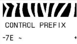 | Set Control Prefix CharacterThe printer looks for this two-digit hex character to indicate the start of a ZPL/ZPL II control instruction.Note·Do not use the same hex value for the control, format, and delimiter character. The printer must see different characters to work properly.Default Value: 7E ~Range: 00 to FFTo change the value shown:1. Press MINUS (-) to move to the next digit position.2. Press PLUS (+) to increase the value of the digit. |
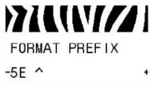 | Set Format Prefix CharacterThe format prefix is a two-digit hex value used as a parameter place marker in ZPL/ZPL II format instructions. The printer looks for this hex character to indicate the start of a ZPL/ZPL II format instruction. See the ZPL Programming Guide for more information.Note·Do not use the same hex value for the control, format, and delimiter character. The printer must see different characters to work properly.Default Value: 5E ^Range: 00 to FFTo change the value shown:1. Press MINUS (-) to move to the next digit position.2. Press PLUS (+) to increase the value of the digit. |
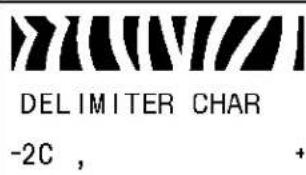 | Set Delimiter CharacterThe delimiter character is a two-digit hex value used as a parameter place marker in ZPL/ZPL II format instructions. See the ZPL Programming Guide for more information.Note·Do not use the same hex value for the control, format, and delimiter character. The printer must see different characters to work properly.Default Value: 2C ,Range: 00 to FFTo change the value shown:1. Press MINUS (-) to move to the next digit position.2. Press PLUS (+) to increase the value of the digit. |
Table 9 · Printer Parameters (Sheet 15 of 22)
| Language/Parameter | Action/Explanation |
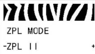 | Select ZPL ModeThe printer remains in the selected mode until it is changed by this parameter or by using a ZPL/ZPL II command. The printer accepts label formats written in either ZPL or ZPL II, eliminating the need to rewrite any ZPL formats that already exist. See the ZPL Programming Guide for more information on the differences between ZPL and ZPL II.Default Value: ZPL IIRange: ZPL II, ZPLTo change the value shown:1. Press PLUS (+) or MINUS (-) to toggle between the options. |
 | Select Media Power-Up OptionThis parameter sets the action of the media when you turn on the printer.Default Value (non-RFID printers): CALIBRATIONDefault Value (RFID printers): FEEDSelections: CALIBRATION, LENGTH, SHORT CAL, NO MOTION, FEEDCalibration adjusts sensor levels and thresholds, determines length, and feeds the media to the next web.Short Cal sets media and web thresholds without adjusting sensor gain, determines length, and feeds the media to the next web.Length determines label length using current sensor values, and feeds the media to the next web.No Motion tells the printer not to move the media. You must manually ensure that the web is positioned correctly, or press feed to position the next web.Feed—feeds the labels to the first registration point.To change the value shown:1. Press PLUS (+) or MINUS (-) to scroll through the options. |
Table 9 · Printer Parameters (Sheet 16 of 22)
| Language/Parameter | Action/Explanation |
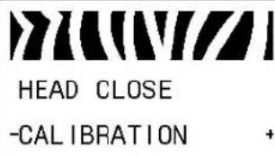 | Select Head Close OptionThis parameter sets the action of the media when you close the printhead.Default Value (non-RFID printers): CALIBRATIONDefault Value (RFID printers): FEEDSelections: CALIBRATION, LENGTH, SHORT CAL, NO MOTION, FEEDCalibration adjusts sensor levels and thresholds, determines length, and feeds the media to the next web.Short Cal sets media and web thresholds without adjusting sensor gain, determines length, and feeds the media to the next web.Length determines label length using current sensor values, and feeds the media to the next web.No Motion tells the printer not to move the media. You must manually ensure that the web is positioned correctly, or press feed to position the next web.Feed—feeds the labels to the first registration point.To change the value shown:1. Press PLUS (+) or MINUS (-) to scroll through the options. |
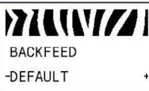 | Select Backfeed SequenceThis parameter sets when label backfeed occurs after a label is removed in some print modes. It has no effect in Rewind mode. This setting is superseded by ~JS when received as part of a label format (see the ZPL Programming Guide for more information).Default Value: DEFAULT (90%)Selections: DEFAULT, AFTER, OFF, BEFORE, 10%, 20%, 30%, 40%, 50%, 60%, 70%, 80%To change the value shown:1. Press PLUS (+) or MINUS (-) to scroll through the options. |
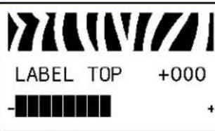 | Adjust Label Top PositionThis parameter adjusts the print position vertically on the label. Positive numbers adjust the label top position farther down the label (away from the printhead) by the specified number of dots. Negative numbers adjust the position up the label (toward the printhead).Default Value: +000Range: -120 to +120To change the value shown:1. Press PLUS (+) to increase the value.2. Press MINUS (-) to decrease the value. |
Table 9 · Printer Parameters (Sheet 17 of 22)
| Language/Parameter | Action/Explanation |
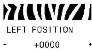 | Adjust Left PositionThis parameter adjusts the print position horizontally on the label. Positive numbers adjust printing to the left by the specified number of dots.Negative numbers shift printing to the right.Default Value: 0000Range: -9999 to +9999 dotsTo change the value shown:1. Press MINUS (-) to move the cursor.2. Press PLUS (+) to change between +/- and to increase the value of the digit. For a negative value, enter the value before changing to the minus sign. |
 | Set the Head Test CountThe printer periodically performs a test of the printhead functionality, called a printhead test or head test. This parameter establishes how many labels are printed between these internal tests.Note • On the 110Xi4, this parameter appears only if the Head Test Count option is installed. Check the printer configuration label for the option.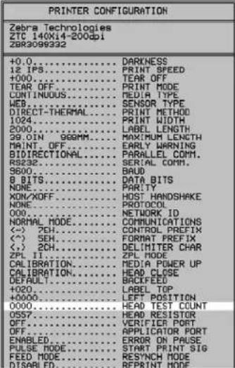 |
| Default: 0000 (disables the test)Range: 0000 to 9999To set the number of labels to print between head tests:1. Press MINUS (-) to move to the next digit position.2. Press PLUS (+) to increase the value of the digit. |
Table 9 · Printer Parameters (Sheet 18 of 22)
| Language/Parameter | Action/Explanation |
 | Set the Verifier PortThe auxiliary port is used to determine how the printer reacts to an online verifier. For more information on the operation of the optional verifier, refer to the documentation provided with that option.Default: OFFSelections: OFF, VER-RPRINT ERR, VER-THRUPUTOFF: The verifier port is off.VER-RPRINT ERR: Label reprinted if verifier detects an error. If a bar code is near the upper edge of the label, the label is fed out far enough to be verified and then backfed to allow the next label to be printed and verified.VER-THRUPUT: Allows greatest throughput but may not indicate a verification error immediately upon detection. May print from one to three labels before an error is recognized and printing stops.To change the value shown:1. Press PLUS (+) or MINUS (-) to scroll through the options. |
 | Set Applicator Port ModeDetermines the action of the applicator port.Note· Set this value as suggested by the applicator manufacturer. Default: OFFSelections: OFF, MODE 1, MODE 2, MODE 3, MODE 4OFF: The applicator port is off.MODE 1: Asserts the ~END_PRINT signal low while the printer is moving the label forward.MODE 2: Asserts the ~END_PRINT signal high while the printer is moving the label forward.MODE 3: Asserts the ~END_PRINT signal low for 20 milliseconds when a label has been completed and positioned. Not asserted during continuous printing modes.MODE 4: Asserts the ~END_PRINT signal high for 20 milliseconds when a label has been completed and positioned. Not asserted during continuous printing modes.To change the value shown:1. Press PLUS (+) or MINUS (-) to scroll through the options. Default: OFFSelections: OFF, MODE 1, MODE 2, MODE 3, MODE 4OFF: The applicator port is off.MODE 1: Asserts the ~END_PRINT signal low while the printer is moving the label forward.MODE 2: Asserts the ~END_PRINT signal high while the printer is moving the label forward.MODE 3: Asserts the ~END_PRINT signal low for 20 milliseconds when a label has been completed and positioned. Not asserted during continuous printing modes.MODE 4: Asserts the ~END_PRINT signal high for 20 milliseconds when a label has been completed and positioned. Not asserted during continuous printing modes.To change the value shown:1. Press PLUS (+) or MINUS (-) to scroll through the options. |
Table 9 • Printer Parameters (Sheet 19 of 22)
| Language/Parameter | Action/Explanation |
 ERROR ON PAUSE-ENABLED + ERROR ON PAUSE-ENABLED + | Set Applicator Error Signal When Printer PausesWhen this option is enabled and the printer is paused, the printer sets the applicator error state.Default: ENABLEDSelections: ENABLED, DISABLEDTo change the value shown:1. Press PLUS (+) or MINUS (-) to toggle between the options. |
 START PRINT SIG-PULSE MODE + START PRINT SIG-PULSE MODE + | Select Start Print SignalThis parameter determines how the printer reacts to the Start Print Signal input on pin 3 of the applicator interface connector at the rear of the printer.Caution • Start Print Signal is set by the applicator manufacturer and should not be changed unless the factory defaults have been reloaded. Please make a note of it. While other choices are valid, the printer must be returned to its designated setting for it to work properly.Default: PULSE MODESelections: PULSE MODE, LEVEL MODE• PULSE MODE—Labels print when the signal transitions from HIGH to LOW.• LEVEL MODE—Labels print as long as the signal is asserted LOW.To change the value shown:1. Press PLUS (+) or MINUS (-) to toggle between the options. |
 RESYNCH MODE-FEED MODE + RESYNCH MODE-FEED MODE + | Select Resynch ModeThis parameter determines how the printer reacts if the label synchronization is lost and the label top is not where expected.Default: FEED MODESelections: FEED MODE, ERROR MODE• FEED MODE—If the label top is not where expected, the printer feeds a blank label to find the label top position.• ERROR MODE—If the label top is not where expected, the printer stops, enters Pause mode, displays the message Error Condition Feed Label, flashes the ERROR light, and asserts the Service Required signal (pin 10 on the Applicator Interface Connector).To resynch the media to the top of the label in Error mode, press PAUSE to exit Pause mode. The ERROR light stops flashing, and the Service Required signal is deactivated. The action of the printer is determined by the Head Close configuration selection (see Select Head Close Option on page 106).To change the value shown:1. Press PLUS (+) or MINUS (-) to toggle between the options. |
Table 9 · Printer Parameters (Sheet 20 of 22)
| Language/Parameter | Action/Explanation | |
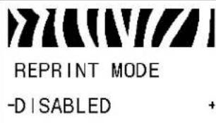 | Set Reprint ModeWhen reprint mode is enabled, you can reprint the last label printed either by issuing the ~PR ZPL command or by pressing MINUS (-) on the control panel.Default Value: DISABLEDSelections: ENABLED, DISABLEDTo change the value shown:1. Press PLUS (+) or MINUS (-) to toggle between the options. | |
| See next column View Sensor SettingsThese parameters are automatically set during the calibration procedure and should be changed only by a qualified service technician. Refer to the ZPL II Programming Guide for information on these parameters.To skip these parameters:1. Press NEXT/SAVE to skip each of the following parameters: | ||
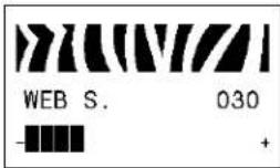 | 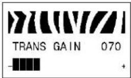 | |
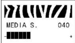 | 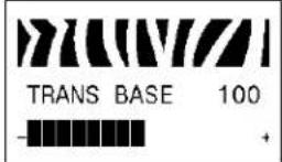 | |
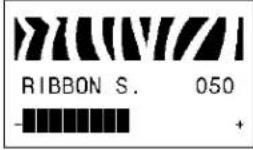 | 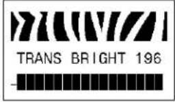 | |
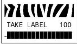 | 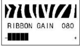 | |
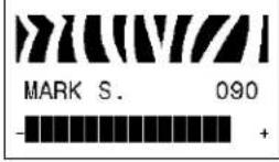 | 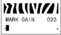 | |
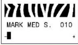 | ||
Table 9 · Printer Parameters (Sheet 21 of 22)
| Language/Parameter | Action/Explanation |
 FORMAT CONVERT-NONE + FORMAT CONVERT-NONE + | Select Format ConvertSelects the bitmap scaling factor. The first number is the original dots per inch (dpi) value; the second, the dpi to which you would like to scale.Default Value: NONESelections: NONE, 150 → 300, 150 → 600, 200 → 600, 300 → 600To change the value shown:1. Press PLUS (+) or MINUS (-) to scroll through the options. |
 IDLE DISPLAY-FW VERSION + IDLE DISPLAY-FW VERSION + | Select Idle DisplayThis parameter selects the LCD options for the real-time clock.Note • If the default value is not selected, pressing PLUS (+) or MINUS (-) briefly displays the firmware version of the printer.Default Value: FIRMWARE (FW) VERSIONSelections: MM/DD/YY (24HR), MM/DD/YY (12HR), DD/MM/YY (24HR), DD/MM/YY (12HR), FW VERSIONTo change the value shown:1. Press PLUS (+) or MINUS (-) to scroll through the options. |
 RTC DATE-01/01/98 + RTC DATE-01/01/98 + | Set Real-Time Clock (RTC) DateThis parameter allows you to set the date following the convention selected in IDLE DISPLAY.To change the value shown:1. Press MINUS (-) to move to the next digit position.2. Press PLUS (+) to change the value of the digit. |
 RTC TIME-01:26 + RTC TIME-01:26 + | Set RTC TimeThis parameter allows you to set the time following the convention selected in IDLE DISPLAY.To change the value shown:1. Press MINUS (-) to move to the next digit position.2. Press PLUS (+) to change the value of the digit. |
 PASSWORD LEVEL-SELECTED ITEMS + PASSWORD LEVEL-SELECTED ITEMS + | Specify Password LevelThis parameter allows you to select whether certain factory-selected menu items or all menu items are password protected.Default Value: SELECTED ITEMSSelections: SELECTED ITEMS, ALL ITEMS1. Press PLUS (+) or MINUS (-) to toggle between the options. |
Table 9 · Printer Parameters (Sheet 22 of 22)
| Language/Parameter | Action/Explanation | ||
 LANGUAGE-ENGLISH + LANGUAGE-ENGLISH + | Select the Display LanguageThis parameter changes the language displayed on the LCD. Each language selection is displayed in the language itself.Default Value: ENGLISHSelections: ENGLISH, SPANISH, FRENCH, GERMAN, ITALIAN, NORWEGIAN, PORTUGUESE, SWEDISH, DANISH, SPANISH 2, DUTCH, FINNISH, JAPANESE, KOREAN, SIMPLIFIED CHINESE, TRADITIONAL CHINESE, RUSSIAN, POLISH | ||
 LANGUAGE-ENGLISH + LANGUAGE-ENGLISH + |  IDIOMA-PORTUGUÊS + IDIOMA-PORTUGUÊS + |  言語-日本 + 言語-日本 + | |
 IDIOMA-ESPANOL + IDIOMA-ESPANOL + |  SPRÄK-SVENSKA + SPRÄK-SVENSKA + |  언어-한국어 + 언어-한국어 + | |
 LANGUAGE-FRANCAIS + LANGUAGE-FRANCAIS + |  SPROG-DANSK + SPROG-DANSK + |  语言-简体中文 + 语言-简体中文 + | |
 Sprache-Deutsch + Sprache-Deutsch + |  IDIOMA-ESPANOL2 + IDIOMA-ESPANOL2 + |  語言-繁體中文 + 語言-繁體中文 + | |
 LINGUA-ITALIANO + LINGUA-ITALIANO + |  TAAL-NEDERLANDS + TAAL-NEDERLANDS + |  Язык-РУССКИЙ + Язык-РУССКИЙ + | |
 SPRÄK-NORSK + SPRÄK-NORSK + |  KIELI-SUOMI + KIELI-SUOMI + |  JEZYK-POLSKI + JEZYK-POLSKI + | |
| To change the value shown:1. Press PLUS (+) or MINUS (-) to scroll through the options. | |||
Additional Control Panel Parameters
Additional parameters appear in the following situations.
- When a Radio Frequency Identification (RFID) reader is installed. The 110Xi4 is RFID-ready, but it does not come with an RFID reader installed. For more information about purchasing the RFID option for these printers, contact your authorized Zebra reseller.
- When a wired print server is installed in the printer. For more information, refer to the ZebraNet 10/100 Print Server User and Reference Guide
- When a wireless print server is installed in the printer. Refer to the ZebraNet Wireless User Guide.
Copies of the print server manuals are available at http://www.zebra.com/manuals or on the user CD that came with your printer.

Notes •
Routine Maintenance

natural_image
Abstract black and white pattern with curved white lines on a black background (no text or symbols)This section provides routine cleaning and maintenance procedures.
Contents
Replacing Printer Components 116
Ordering Replacement Parts 116
Recycling Printer Components 116
Lubrication 116
Cleaning Schedule and Procedures.... 117
Clean the Exterior 117
Clean the Media Compartment 117
Clean the Printhead and Platen Roller. 118
Clean the Sensors 121
Clean the Snap Plate 124
Clean the Cutter....125
Replace the Fuse....126
Replacing Printer Components
Some printer components, such as the printhead and platen roller, may wear out over time and can be replaced easily. Regular cleaning may extend the life of some of these components. See Cleaning Schedule and Procedures on page 117 for the recommended cleaning intervals.
Ordering Replacement Parts
For optimal printing quality and proper printer performance across our product line, Zebra strongly recommends the use of genuine Zebra ^TM supplies as part of the total solution.
Contact your authorized Zebra reseller for part ordering information, or see Contacts on page 11 for contact addresses and telephone numbers.
Recycling Printer Components
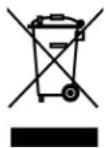
The majority of this printer's components are recyclable. The printer's main logic board includes a battery that you should dispose of properly.
Do not dispose of any printer components in unsorted municipal waste. Please dispose of the battery according to your local regulations, and recycle the other printer components according to your local standards. For more information, see http://www.zebra.com/environment.
Lubrication
Other than lubricating the cutter blade after approximately 60,000 cuts, no lubrication is needed for this printer.

Caution • The cutter blade is sharp. Do not touch or rub the blade with your fingers.
Caution • Some commercially available lubricants will damage the finish and the mechanical parts if used inappropriately on this printer.
Cleaning Schedule and Procedures
Cleaning your printer regularly maintains print quality and may extend the life of the printer. The recommended cleaning schedule is shown in Table 11. See the following pages for specific procedures.
Caution • While performing any tasks near an open printhead, remove all rings, watches, hanging necklaces, identification badges, or other metallic objects that could touch the printhead. You are not required to turn off the printer power when working near an open printhead, but Zebra recommends it as a precaution. If you turn off the power, you will lose all temporary settings, such as label formats, and you must reload them before you resume printing.
Caution • Use only the cleaning agents indicated. Zebra is not responsible for damage caused by any other fluids being used on this printer.
Table 11 · Recommended Printer Cleaning Schedule
| Area Method Interval | ||
| Printhead Solvent* Perform these procedures at the following times: | ||
| Platen roller Solvent* | When CLEAN HEAD NOW appears.Direct Thermal Print Mode: After every roll of labels or 500 ft (150 m) of fanfold labels.Thermal Transfer Print Mode: After every roll (1500 ft or 450 m) of ribbon. | |
| Transmissive (media) sensor Air blow † | ||
| Black mark sensor | Air blow† | |
| Media path | Solvent* | |
| Ribbon sensor | Air blow | |
| Label-available sensors | Air blow Every 6 months, or as needed | |
| Tear-off/peel-off bar | Solvent* | |
| Snap plate | Solvent* As needed | |
| Cutter | Solvent* | |
* Zebra recommends using Preventive Maintenance Kit (part number 47362). In place of this kit, you may use a clean swab dipped in a solution of isopropyl alcohol (minimum 90%) and deionized water (maximum 10%).
† If using canned air, it is recommended that you turn off the printer before cleaning.
Clean the Exterior
Clean the outside surfaces of the printer with a lint-free cloth. Use a mild detergent solution or desktop cleaner sparingly, as needed.
Clean the Media Compartment
After every four rolls of media, inspect the media compartment. Use a soft bristle brush or a vacuum cleaner to remove any dirt and lint from the interior of the printer.
Clean the Printhead and Platen Roller
If print quality does not improve after you perform this procedure, clean the printhead with Save-a-Printhead cleaning film. This specially coated material removes contamination buildup without damaging the printhead. Call your authorized Zebra reseller or distributor for more information.
Cleaning intervals are as follows, based on the printhead resolution:
For 203 and 300 dpi printers Clean the printhead after every roll (1500 feet or 450 m) of thermal transfer ribbon or after every roll (500 feet or 150 m) of direct thermal labels or when CLEAN HEAD NOW appears on the LCD. Clean the printhead more often if you see inconsistent print quality, such as voids in the bar code or graphics.
For 600 dpi printers Clean the printhead after each roll (500 feet or 150 m) of labels or when CLEAN HEAD NOW appears on the LCD. Clean the printhead more often if you see inconsistent print quality, such as voids in the bar code or graphics.

If power is removed from a 600 dpi printer when cleaning the printhead, the CLEAN HEAD NOW warning shown on the LCD will not disappear.

Caution • The printhead may be hot and can cause severe burns. Allow the printhead to cool.

Caution • Before touching the printhead assembly, discharge any built-up static electricity by touching the metal printer frame or by using an anti-static wriststrap and mat.
Caution • While performing any tasks near an open printhead, remove all rings, watches, hanging necklaces, identification badges, or other metallic objects that could touch the printhead. You are not required to turn off the printer power when working near an open printhead, but Zebra recommends it as a precaution. If you turn off the power, you will lose all temporary settings, such as label formats, and you must reload them before you resume printing.
To clean the printhead and platen roller, complete these steps:
- Open the printhead assembly by rotating the printhead-open lever (1) counter-clockwise.
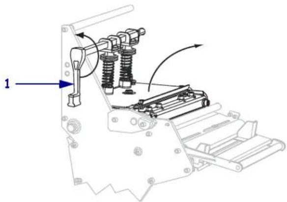
natural_image
Mechanical assembly diagram showing spring-loaded components and a numbered label (1), no readable text or symbols present.-
Remove the media and ribbon (if loaded).
-
Using the swab from the Preventive Maintenance Kit (part number 47362), wipe along the brown strip on the printhead assembly from end to end. In place of the Preventive Maintenance Kit, you may use a clean swab dipped in a solution of isopropyl alcohol (minimum 90%) and deionized water (maximum 10%). Allow the solvent to evaporate.
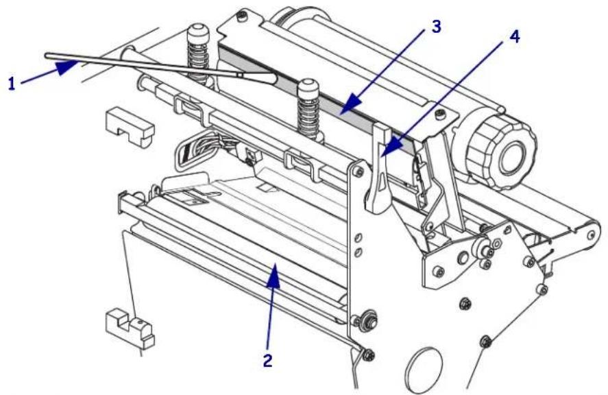
| 1 | Swab |
| 2 | Platen roller |
| 3 | Printhead print elements |
| 4 | Printhead-open lever |
- While manually rotating the platen roller, clean it thoroughly with the swab. Allow the solvent to evaporate.
- Reload the media and the ribbon (if required).
- Push down the printhead assembly (1), and then rotate the printhead-open lever (2) clockwise until it locks into place.
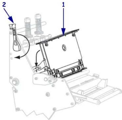
Clean the Sensors
Brush or vacuum any accumulated paper lint and dust off the sensors. Clean the sensors according to the recommendations in Cleaning Schedule and Procedures on page 117.
Ribbon and Label-Available Sensor Locations
The ribbon sensor and optional label-available sensor are shown in Figure 16.
Figure 16 · Sensor Locations
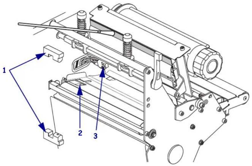
| 1 | Label-available sensors |
| 2 | Black mark sensor |
| 3 | Ribbon sensor |
Transmissive Media Sensor Locations
The locations of the upper and lower transmissive media sensors are shown in Figure 17 and Figure 18.
Figure 17 · Upper Media Sensor
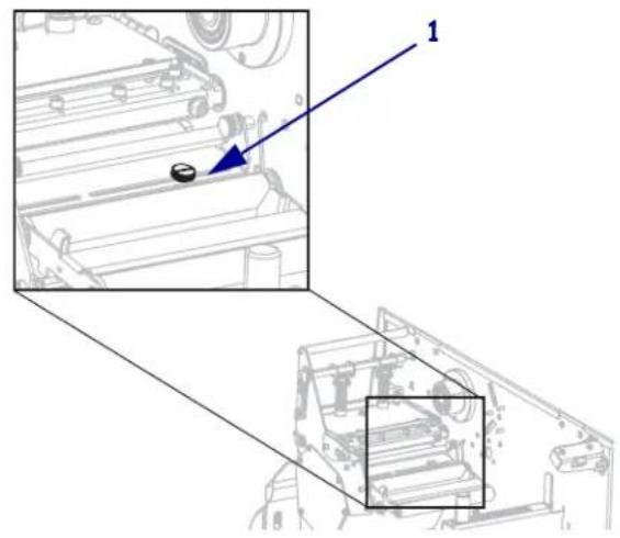
natural_image
Technical diagram showing a mechanical assembly with a highlighted component and an inset view of a vehicle chassis (no text or symbols present)1 Upper media sensor
Figure 18 · Lower Media Sensor
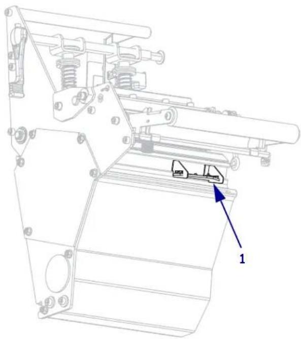
natural_image
Technical line drawing of a mechanical assembly with no visible text or symbols1 Lower media sensor
Media Out Sensor Location
The location of the media out sensor is shown in Figure 19.
Figure 19 • Media Out Sensor
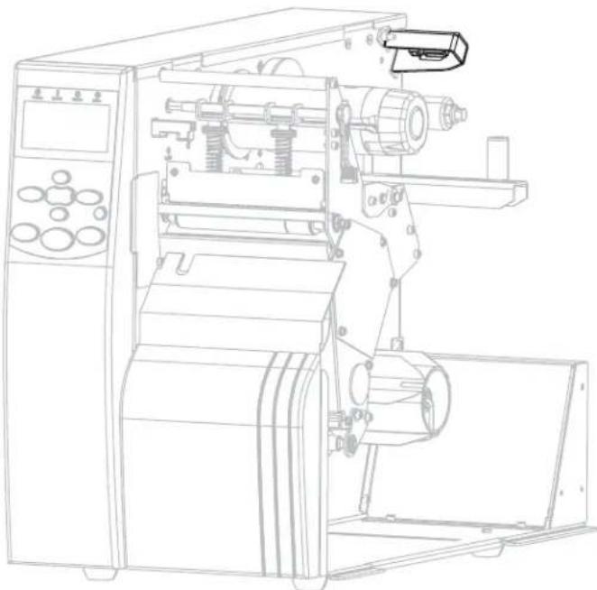
natural_image
Technical line drawing of an industrial machine with internal components and control panel (no text or symbols)Clean the Snap Plate
Clean the snap plate when label adhesive or a label is stuck to the underside. Figure 20 shows the location of the snap plate.
Figure 20 · Snap Plate Location
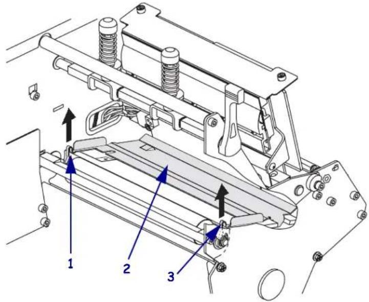
| 1 | Left loop |
| 2 | Snap plate |
| 3 | Right loop |
To clean the snap plate, complete these steps:
-
See Figure 20. Insert a small-blade screwdriver or similar tool into the loop on the left side of the snap plate.
-
Gently lift the left side of the snap plate.
-
Insert a small-blade screwdriver or similar tool into the loop on the right side of the snap plate.
-
Gently lift the right side of the snap plate.
-
Remove the snap plate from the printer.
-
Using the swab from the Preventive Maintenance Kit (part number 47362), clean the snap plate. In place of the Preventive Maintenance Kit, you may use a clean swab or soft cloth dipped in a solution of isopropyl alcohol (minimum 90%) and deionized water (maximum 10%). Allow the solvent to evaporate.
-
To reinstall the snap plate, insert the two tabs on the bottom of the snap plate into the two slots of the media path.
- Slide the snap plate toward you.
- Press down on the loops to lock the snap plate into place.
Clean the Cutter
If the cutter is not cutting the labels cleanly or if it jams with labels, clean the cutter.

Caution • The cutter blade is sharp. Do not touch or rub the blade with your fingers.
To clean the cutter, complete these steps:
- Turn off (O) the printer.
- Unplug the power cord.
- Using the swab from the Preventive Maintenance Kit (part number 47362), clean the stationary cutter blade. In place of the Preventive Maintenance Kit, you may use a clean swab dipped in a solution of isopropyl alcohol (minimum 90%) and deionized water (maximum 10%). Allow the solvent to evaporate.
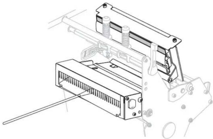
natural_image
Technical line drawing of a mechanical device with housing and mounting bracket (no text or symbols)- If cleaning does not remove label fragments and adhesive, contact an authorized service technician.
Replace the Fuse
The instructions that follow are for the 140Xi4, 170Xi4, and 220Xi4 printers only. Fuses are not user-replaceable in the 110Xi4.

Caution • Turn the AC power switch off (O) and remove the power cord before performing this procedure.
The printer uses a metric-style fuse (5 × 20 mm IEC) rated at F5A, 250 V. The AC power entry module comes with two approved fuses in the fuse holder: one is in-circuit, and the second is provided as a spare. The end caps of the fuse must bear the certification mark of a known international safety organization (see Figure 5 on page 29).
To replace a faulty fuse, complete these steps:
- Use a small-blade screwdriver or similar tool to remove the fuse holder.
The fuse holder is part of the AC power entry module at the rear of the printer (Figure 21).
Figure 21 · AC Power Entry Module
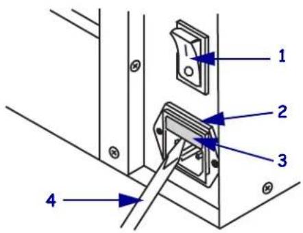
| 1 | Power switch |
| 2 | Fuse holder |
| 3 | AC power entry module |
| 4 | Small-blade screwdriver |

- Remove the faulty fuse and install a new fuse in the in-circuit position (Figure 22).
Important • If you use the spare fuse, be sure to order a replacement fuse from an authorized Zebra distributor. The spare fuse should be the exact type and rating as the original in-circuit fuse.
Figure 22 • Fuse Locations
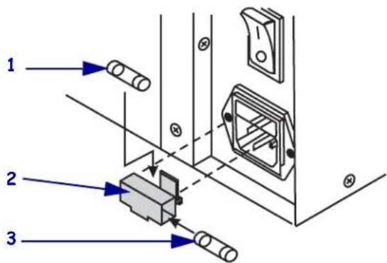
| 1 | In-circuit fuse |
| 2 | Fuse holder |
| 3 | Spare fuse |
-
Snap the fuse holder back into the AC power entry module.
-
Reconnect the power cord, and turn the printer on (1).
Note • If the printer does not power on, an internal component failure may have occurred, and the printer requires servicing by an authorized service technician.


Notes •
Troubleshooting

natural_image
Abstract black and white pattern with curved white lines on black background (no text or symbols)This section provides information about errors that you might need to troubleshoot. Assorted diagnostic tests are included.
Contents
Troubleshooting Checklists 130
LCD Error Messages 131
Print Quality Problems 137
Calibration Problems 141
Communications Problems 142
Ribbon Problems 143
Miscellaneous Printer Problems.... 144
Printer Diagnostics....146
Power-On Self Test 146
CANCEL Self Test 147
PAUSE Self Test 148
FEED Self Test. 149
FEED and PAUSE Self Test. 152
Communications Diagnostics Test. 153
Sensor Profile 154
Troubleshooting Checklists
If an error condition exists with the printer, review this checklist:
☐ Is there an error message on the LCD? If yes, see LCD Error Messages on page 131.
☐ Are noncontinuous labels being treated as continuous labels? If yes, see Calibrate Media and Ribbon Sensor Sensitivity on page 101.
☐ Is the CHECK RIBBON light on when ribbon is loaded properly? If yes, see Calibrate Media and Ribbon Sensor Sensitivity on page 101.
☐ Are you experiencing problems with print quality? If yes, see Print Quality Problems on page 137.
☐ Are you experiencing communications problems? If yes, see Communications Problems on page 142.
If the labels are not printing or advancing correctly, review this checklist:
☐ Are you using the correct type of labels? Review the types of label in Types of Media on page 31.
☐ Are you using a label that is narrower than the maximum print width? See Set Print Width on page 94.
☐ Review the label- and ribbon-loading illustrations in Print Modes and Printer Options on page 36 and Load Ribbon on page 68.
☐ Does the printhead need to be adjusted? See Adjust Printhead Pressure and Toggle Position on page 81 for more information.
☐ Do the sensors need to be calibrated? See Calibrate Media and Ribbon Sensor Sensitivity on page 101 for more information.
If none of the above suggestions correct the problem, review this checklist:
☐ Perform one or more of the self-tests given in Printer Diagnostics on page 146. Use the results to help identify the problem.
☐ If you are still having problems, see Contacts on page 11 for customer support information.
LCD Error Messages
The LCD displays messages when there is an error. See Table 12 for LCD errors, the possible causes, and the recommended solutions.
Table 12 · LCD Error Messages
| LCD Display/Printer Condition | Possible Cause Recommended Solution | |
 ERROR CONDITION INVALID HEADThe ERROR light flashes. ERROR CONDITION INVALID HEADThe ERROR light flashes. | The printhead was replaced with one that is not a genuine Zebra ^TM printhead. | Install a genuine Zebra ^TM printhead. |
 ERROR CONDITION RIBBON OUTThe printer stops; the RIBBON light is on; the ERROR light flashes. ERROR CONDITION RIBBON OUTThe printer stops; the RIBBON light is on; the ERROR light flashes. | In thermal transfer mode, ribbon is not loaded or incorrectly loaded. | Load ribbon correctly. See Load Ribbon on page 68. |
| In thermal transfer mode, the ribbon sensor is not detecting ribbon. | 1. Load ribbon correctly. See Load Ribbon on page 68.2. Calibrate the sensors. See Calibrate Media and Ribbon Sensor Sensitivity on page 101. | |
| In thermal transfer mode, media is blocking the ribbon sensor. | 1. Load media correctly. See Print Modes and Printer Options on page 36.2. Calibrate the sensors. See Calibrate Media and Ribbon Sensor Sensitivity on page 101. | |
| In thermal transfer mode, the printer did not detect the ribbon even though it is loaded correctly. | 1. Print a sensor profile. See Print Sensor Profile on page 100. The ribbon out threshold (1) is likely too high, above the black area that indicates where the ribbon is detected (2).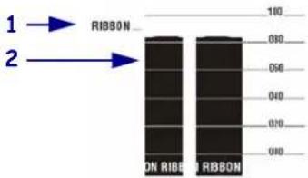 2. Calibrate the sensors or load printer defaults. See Calibrate Media and Ribbon Sensor Sensitivity on page 101 or LOAD DEFAULTS on page 87. 2. Calibrate the sensors or load printer defaults. See Calibrate Media and Ribbon Sensor Sensitivity on page 101 or LOAD DEFAULTS on page 87. | |
 WARNINGRIBBON INThe RIBBON light is on; theERROR light flashes. WARNINGRIBBON INThe RIBBON light is on; theERROR light flashes. | Ribbon is loaded, but the printer is set for direct thermal mode. | Ribbon is not required with direct thermal media. If you are using direct thermal media, remove the ribbon. This error message will not affect printing. |
| If you are using thermal transfer media, which requires ribbon, set the printer for Thermal Transfer mode. See Select Print Method on page 94. | ||
 ERROR CONDITIONPAPER OUTThe printer stops; theMEDIA light is on; theERROR light flashes. ERROR CONDITIONPAPER OUTThe printer stops; theMEDIA light is on; theERROR light flashes. | The media is not loaded or is loaded incorrectly. | Load media correctly. See Print Modes and Printer Options on page 36. |
| Misaligned media sensor. Check position of the media sensor. | ||
| The printer is set for noncontinuous media, but continuous media is loaded. | Install proper media type, or reset printer for current media type and perform calibration. | |
 ERROR CONDITIONHEAD OPENThe printer stops; theERROR light flashes. ERROR CONDITIONHEAD OPENThe printer stops; theERROR light flashes. | The printhead is not fully closed. Close printhead completely. | |
| The head open sensor is not working properly. | Call a service technician. | |
 THERMISTORFAULTThe ERROR light flashes. THERMISTORFAULTThe ERROR light flashes. | The printhead has a faulty thermistor. | Call a service technician. |
 WARNINGHEAD COLD WARNINGHEAD COLD |  Caution • An improperly connected printhead data or power cable can cause these error messages. The printhead may be hot enough to cause severe burns. Allow the printhead to cool. Caution • An improperly connected printhead data or power cable can cause these error messages. The printhead may be hot enough to cause severe burns. Allow the printhead to cool. | |
| The printhead data cable is not properly connected. | Caution • Turn off (O) the printer before performing this procedure.Failure to do so can damage the printhead.1. Turn off (O) the printer.2. Disconnect and reconnect the data cable to the printhead.3. Ensure that the cable connector is fully inserted into the printhead connector.4. Turn on (I) the printer. | |
 THERMISTORFAULT THERMISTORFAULT | ||
 ERROR CONDITIONHEAD ELEMENT BAD ERROR CONDITIONHEAD ELEMENT BAD | The printhead has a faulty thermistor. | Call a service technician. |
| The printer stops; the ERROR light is on; the printer cycles through these three messages. | ||
 WARNINGHEAD COLDThe printer prints while theERROR light flashes. WARNINGHEAD COLDThe printer prints while theERROR light flashes. |  Caution • An improperly connected printhead data or power cable can cause this error message. The printhead may be hot enough to cause severe burns. Allow the printhead to cool. Caution • An improperly connected printhead data or power cable can cause this error message. The printhead may be hot enough to cause severe burns. Allow the printhead to cool. | |
| The printhead temperature is approaching its lower operating limit. | Continue printing while the printhead reaches the correct operating temperature. If the error remains, the environment may be too cold for proper printing. Relocate the printer to a warmer area. | |
| The printhead data cable is not properly connected. | Caution • Turn off (O) the printer before performing this procedure.Failure to do so can damage the printhead.1. Turn off (O) the printer.2. Disconnect and reconnect the data cable to the printhead.3. Ensure that the cable connector is fully inserted into the printhead connector.4. Turn on (I) the printer. | |
| The printhead has a faulty thermistor. | Call a service technician. | |
 WARNINGHEAD TOO HOTThe printer stops; theERROR light flashes. WARNINGHEAD TOO HOTThe printer stops; theERROR light flashes. |  Caution • The printhead may be hot enough to cause severe burns. Allow the printhead to cool. Caution • The printhead may be hot enough to cause severe burns. Allow the printhead to cool. | |
| The printhead is over temperature. Allow the printer to cool. Printing automatically resumes when the printhead elements cool to an acceptable operating temperature. | ||
 DEFRAGMENTINGDO NOT POWER OFFThe printer stops. DEFRAGMENTINGDO NOT POWER OFFThe printer stops. | The printer is defragmenting memory. | Caution • Do NOT turn off the printer power during defragmenting. Doing so can damage the printer.Allow the printer to finish defragmenting. If you get this error message frequently, check your label formats. Formats that write to and erase memory frequently may cause the printer to defragment often. Using properly coded label formats usually minimizes the need for defragmenting. If this error message does not go away, contact Technical Support. The printer requires service. |
 ERROR CONDITION CUTTER JAMMEDThe printer stops; the ERROR light flashes. ERROR CONDITION CUTTER JAMMEDThe printer stops; the ERROR light flashes. |  Caution • The cutter blade is sharp. Do not touch or rub the blade with your fingers. Caution • The cutter blade is sharp. Do not touch or rub the blade with your fingers. | |
| The cutter blade is in the media path.There is not enough memory to perform the function specified on the second line of the error message. | Turn off the printer power and unplug the printer. Inspect the cutter module for debris and clean as needed following the cleaning instructions inClean the Cutter on page 125.Free up some of the printer's memory by adjusting the label format or printer parameters. One way to free up memory is to adjust the print width to the actual width of the label instead of leaving the print width set to the default. SeeSet Print Widthon page 94. | |
| Ensure that the device, such as FLASH memory or PCMCIA card, is installed and not write protected or full. | ||
| Ensure that the data is not directed to a device that is not installed or is unavailable. | ||
| Refer to theMaintenance Manualfor more information about the specified function. | ||
Print Quality Problems
Table 13 identifies problems with print quality, the possible causes, and the recommended solutions.
Table 13 · Print Quality Problems
| Problem Possible Cause | Recommended Solution | |
| General print quality issues | The printer is set at the incorrect print speed. | For optimal print quality, set the print speed to the lowest possible setting for your application via control panel, the driver, or the software. See Adjust Print Speed on page 91. You may want to perform the FEED Self Test on page 149. |
| You are using an incorrect combination of labels and ribbon for your application. | 1. Switch to a different type of media or ribbon to try to find a compatible combination.2. If necessary, consult for information and advice. | |
| The printer is set at an incorrect darkness level. | For optimal print quality, set the darkness to the lowest possible setting for your application via the control panel, the driver, or the software. See Adjust Print Speed on page 91. You may want to perform the FEED Self Test on page 149 to determine the ideal darkness setting. | |
| The printhead is dirty. Clean the | printhead. See Clean the Printhead and Platen Roller on page 118. | |
| Incorrect or uneven printhead pressure. | Set the printhead pressure to the minimum needed for good print quality. See Adjust Printhead Pressure and Toggle Position on page 81. | |
| The printhead is improperly balanced. | Call a service technician. | |
| Long tracks of missing print on several labels | Print element damaged. Call a service technician. | |
| Wrinkled ribbon. See wrinkled ribbon causes and solutions in this table. | ||
| Wrinkled ribbon Ribbon | was fed through the ribbon system incorrectly. | Load the ribbon correctly. See Load Ribbon on page 68. |
| Incorrect burn temperature. Set the | darkness to the lowest possible setting for good print quality. See Adjust Print Darkness on page 91. | |
| Incorrect or uneven printhead pressure. | Set the printhead pressure to the minimum needed for good print quality. See Adjust Printhead Pressure and Toggle Position on page 81. | |
| Media not feeding properly; “walking” from side to side. | Make sure that media is snug by adjusting the media guide, or call a service technician. | |
| The strip plate needs adjusting. | Call a service technician. | |
| The printhead needs vertical adjustment. | Call a service technician. | |
| The printhead is improperly balanced. | Call a service technician. | |
| The printhead and platen roller need to be realigned. | Call a service technician. | |
| Fine, angular gray lines on blank labels | Wrinkled ribbon. See wrinkled ribbon causes and solutions in this table. | |
| Printing too light or too dark over the entire label | The media is not designed for high-speed operation. | Replace supplies with those recommended for high-speed operation. |
| You are using an incorrect combination of media and ribbon for your application. | Switch to a different type of media or ribbon to try to find a compatible combination.If necessary, consult your authorized Zebra reseller or distributor for information and advice. | |
| You are using ribbon with direct thermal media. | Direct thermal media does not require ribbon. To check if you are using direct thermal media, perform the label scratch test in When to Use Ribbon on page 33. | |
| Incorrect or uneven printhead pressure. | Set the pressure to the minimum needed. See Adjust Printhead Pressure and Toggle Position on page 81. | |
| Smudge marks on labels | The media or ribbon is not designed for high-speed operation. | Replace supplies with those recommended for high-speed operation. |
| Problem Possible Cause | Recommended Solution | |
| Misregistration/skips labels | The printer is not calibrated. Recalibrate the printer. | |
| The media sensor is not positioned correctly. | Perform media sensor position adjustment. | |
| Improper label format. Use correct label format. | ||
| Misregistration and misprint of one to three labels | The platen roller is dirty. | See Clean the Printhead and Platen Roller on page 118. |
| The media sensor is not positioned correctly. | Place the media sensor in the proper position. | |
| Media does not meet specifications. | Use media that meets specifications. | |
| Vertical drift in top-of-form position | The printer is out of calibration. Recalibrate the printer. | |
| Vertical drift occurs during normal printer operation.[WKKS] Note • A vertical drift of ±4 to 6 dot rows (approximately 0.5 mm) is within normal tolerances. | Calibrate the printer. See Calibrate Media and Ribbon Sensor Sensitivity on page 101. | |
| The platen roller is dirty. Clean the platen roller. See Clean the Printhead and Platen Roller on page 118. | ||
| Vertical image or label drift | The printer is using non-continuous labels but is configured in continuous mode. | Configure the printer for non-continuous and run calibration routine, if necessary. |
| The media sensor is positioned incorrectly. | Ensure that the media sensor is properly positioned to read a single/consistent interlabel gap. | |
| The media sensor is calibrated improperly. | See Calibrate Media and Ribbon Sensor Sensitivity on page 101. | |
| The platen roller is dirty. Clean the platen roller. See Clean the Printhead and Platen Roller on page 118. | ||
| Improper printhead pressure settings (toggles). | Adjust the printhead pressure to ensure proper functionality. | |
| Improperly loaded media. Verify that the printer is loaded properly. | ||
| Incompatible media. Ensure that the interlabel gaps or notches are 2 to 4 mm and consistently placed. Media must not exceed minimum specifications for mode of operation. | ||
| Problem Possible Cause | Recommended Solution | |
| The bar code printed on a label does not scan. | The bar code is not within specifications because the print is too light or too dark. | Perform the FEED Self Test on page 149. Adjust the darkness or print speed settings as necessary. |
| Not enough blank space around the bar code. | Leave at least 1/8 in. (3.2 mm) between the bar code and other printed areas on the label and between the bar code and the edge of the label. | |
Calibration Problems
Table 14 identifies problems with calibration, the possible causes, and the recommended solutions.
Table 14 · Calibration Problems
| Problem Possible Cause | Recommended Solution | |
| Loss of printing registration on labels. Excessive vertical drift in top-of-form registration. | The platen roller is dirty. Clean the | the platen roller according to the instructions inClean the Printhead and Platen Roller on page 118. |
| Media guides are positioned improperly. | Ensure that the media guides are properly positioned. | |
| The media type is set incorrectly. | Set the printer for the correct media type (non-continuous or continuous). SeeSet Media Type on page 93. | |
| Auto Calibrate failed. | Media or ribbon is loaded incorrectly. | Ensure that media and ribbon are loaded correctly. |
| The sensors could not detect the media or ribbon. | Manually calibrate the printer. SeeCalibrate Media and Ribbon Sensor Sensitivity on page 101. | |
| The sensors are dirty or positioned improperly. | Ensure that the sensors are clean and properly positioned. |
Communications Problems
Table 15 identifies problems with communications, the possible causes, and the recommended solutions.
Table 15 · Communications Problems
| Problem Possible Cause Recommended Solution | ||
| A label format was sent to the printer but was not recognized. The DATA light does not flash. | The communication parameters are incorrect. | Check the printer driver or software communications settings (if applicable). |
| If you are using serial communication, check the serial port setting in the control panel menu. See Set Serial Communications on page 102. | ||
| If you are using serial communication, make sure that you are using a null modem cable or a null modem adapter. | ||
| Using the control panel controls, check the protocol setting. It should be set to NONE. See Set Protocol on page 103. | ||
| If a driver is used, check the driver communication settings for your connection. | ||
| A label format was sent to the printer. Several labels print, then the printer skips, misplaces, misses, or distorts the image on the label. | The serial communication settings are incorrect. | Ensure that the flow control settings match. |
| Check the communication cable length. See Table 3 on page 23 for requirements. | ||
| Check the printer driver or software communications settings (if applicable). | ||
| A label format was sent to the printer but was not recognized. The DATA light flashes but no printing occurs. | The prefix and delimiter characters set in the printer do not match the ones in the label format. | Verify the prefix and delimiter characters. See Set Format Prefix Character on page 104 and Set Delimiter Character on page 104 for the requirements. |
| Incorrect data is being sent to the printer. | Check the communication settings on the computer. Ensure that they match the printer settings. | |
| Ensure that ZPL II is being used. | ||
| If the problem continues, check the ZPL II format for changes to ^CC, ^CT, and ^CD. | ||
Ribbon Problems
Table 16 identifies problems that may occur with ribbon, the possible causes, and the recommended solutions.
Table 16 · Ribbon Problems
| Problem Possible Cause | Recommended Solution | |
| Broken or melted ribbon | Darkness setting too high. | 1. Reduce the darkness setting.2. Clean the printhead thoroughly. |
| The printer does not detect when the ribbon runs out. | The printer was calibrated without ribbon. Later, ribbon was inserted without the user recalibrating the printer or loading printer defaults. | Calibrate the printer, this time using ribbon, or load printer defaults. See Calibrate Media and Ribbon Sensor Sensitivity on page 101. |
| In thermal transfer mode, the printer did not detect the ribbon even though it is loaded correctly. | ||
| The ribbon light is on even though ribbon is loaded correctly. | The printer was not calibrated for the label and ribbon being used. | Perform the calibration procedure in Calibrate Media and Ribbon Sensor Sensitivity on page 101. |
Miscellaneous Printer Problems
Table 17 identifies miscellaneous problems with the printer, the possible causes, and the recommended solutions.
Table 17 • Miscellaneous Printer Problems
| Problem Possible Cause | Recommended Solution | |
| The LCD displays a language that I cannot read | The language parameter was changed through the control panel or a firmware command. | 1. Press SETUP/EXIT to enter configuration mode.2. Press MINUS (-).The printer displays the LANGUAGE parameter in the current language. Even if you cannot recognize the characters displayed, you can still scroll to another language.3. Press PLUS (+) or MINUS (-) to scroll through the choices until you find a language that you can read.4. Press SETUP/EXIT.The LCD displays SAVE CHANGES in the original language.5. Press NEXT/SAVE to exit configuration mode and save the changes (if the language does not change, you may need to scroll to a different save option by pressing PLUS (+) or MINUS (-) in the previous step).6. Repeat this process, if necessary, until you reach the desired language. |
| The LCD is missing characters or parts of characters | The LCD may need replacing. Call a service technician. | |
| Changes in parameter settings did not take effect | Parameters are set incorrectly. | 1. Set parameters and save permanently.2. Turn the printer off (O) and then on (I). |
| A firmware command turned off the ability to change the parameter. | Refer to the Programming Guide for the printer language being used, or call a service technician. | |
| A firmware command changed the parameter back to the previous setting. | Refer to the Programming Guide for the printer language being used, or call a service technician. | |
| If the problem continues, there may be a problem with the main logic board. | Call a service technician. | |
| The printer fails to calibrate or detect the top of the label. | The printer was not calibrated for the label being used. | Perform the calibration procedure in Calibrate Media and Ribbon Sensor Sensitivity on page 101. |
| The printer is configured for continuous media. | Set the media type to noncontinuous media. See Set Media Type on page 93. | |
| The driver or software configuration is not set correctly. | Driver or software settings produce commands that can overwrite the printer configuration. Check the driver or software media-related setting. | |
| Non-continuous labels are being treated as continuous labels. | The printer was not calibrated for the media being used. | Perform the calibration procedure in Calibrate Media and Ribbon Sensor Sensitivity on page 101. |
| The printer is configured for continuous media. | Set the media type to noncontinuous media. See Set Media Type on page 93. | |
| All lights are on, but nothing displays on the LCD, and the printer locks up. | Internal electronic or firmware failure. | Call a service technician. |
| The printer locks up while running the Power-On Self Test. | Main logic board failure. Call a service technician. | |
Printer Diagnostics
Self tests and other diagnostics provide specific information about the condition of the printer. The self tests produce sample printouts and provide specific information that helps determine the operating conditions for the printer. The most commonly used are the Power-On and the CANCEL self tests.

Important • Use full-width media when performing self tests. If your media is not wide enough, the test labels may print on the platen roller. To prevent this from happening, check the print width using Set Print Width on page 94, and ensure that the width is correct for the media that you are using.
Each self test is enabled by pressing a specific control panel key or combination of keys while turning on (l) the printer power. Keep the key(s) pressed until the first indicator light turns off. The selected self test automatically starts at the end of the Power-On Self Test.

Note •
- When performing these self tests, do not send data to the printer from the host.
- If your media is shorter than the label to be printed, the test label continues on the next label.
- When canceling a self test prior to its actual completion, always reset the printer by turning it off (O) and then on (I).
- If printer is in applicator mode and the liner is being taken up by the applicator, the operator must manually remove the labels as they become available.
Power-On Self Test
A Power-On Self Test (POST) is performed each time the printer is turned on (1). During this test, the control panel lights (LEDs) turn on and off to ensure proper operation. At the end of this self test, only the POWER LED remains lit. When the Power-On Self Test is complete, the media is advanced to the proper position.
To initiate the Power-On Self Test, complete these steps:
1. Turn on (I) the printer.
The POWER LED illuminates. The other control panel LEDs and the LCD monitor the progress and indicate the results of the individual tests. All messages during the POST display in English; however, if the test fails, the resulting messages cycle through the international languages as well.
CANCEL Self Test
The CANCEL self test prints a configuration label (Figure 23).
To perform the CANCEL Self Test, complete these steps:
-
Turn off (O) the printer.
-
Press and hold CANCEL while turning on (I) the printer. Hold CANCEL until the first control panel light turns off.
A printer configuration label prints (Figure 23).
Figure 23 · Sample Configuration Label
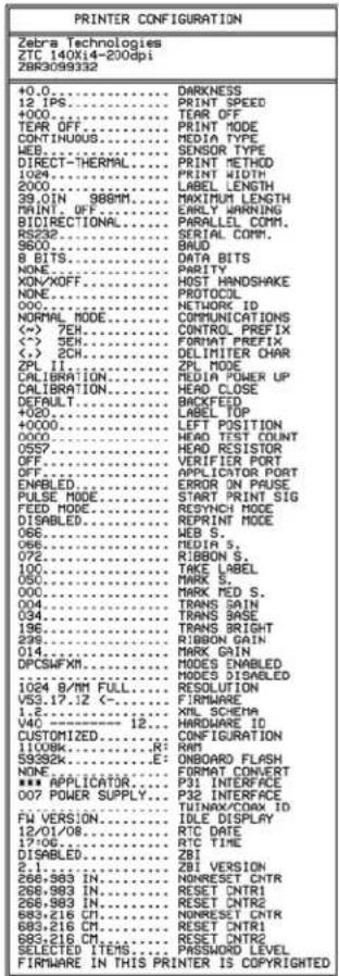
PAUSE Self Test
This self test can be used to provide the test labels required when making adjustments to the printer's mechanical assemblies or to determine if any printhead elements are not working. Figure 24 shows a sample printout.
To perform a PAUSE self test, complete these steps:
-
Turn off (O) the printer.
-
Press and hold PAUSE while turning on (I) the printer. Hold PAUSE until the first control panel light turns off.
- The initial self test prints 15 labels at the printer's slowest speed, and then automatically pauses the printer. Each time PAUSE is pressed, an additional 15 labels print. Figure 24 shows a sample of the labels.
Figure 24 • PAUSE Test Label

- While the printer is paused, pressing CANCEL alters the self test. Each time PAUSE is pressed, 15 labels print at 6 in. (152 mm) per second.
- While the printer is paused, pressing CANCEL again alters the self test a second time. Each time PAUSE is pressed, 50 labels print at the printer's slowest speed
- While the printer is paused, pressing CANCEL again alters the self test a third time. Each time PAUSE is pressed, 50 labels print at 6 in. (152 mm) per second.
- While the printer is paused, pressing CANCEL again alters the self test a fourth time. Each time PAUSE is pressed, 15 labels print at the printer's maximum speed.
- To exit this self test at any time, press and hold CANCEL.
FEED Self Test
Different types of media may require different darkness settings. This section contains a simple but effective method for determining the ideal darkness for printing bar codes that are within specifications.
During the FEED self test, labels are printed at different darkness settings at two different print speeds. The relative darkness and the print speed are printed on each label. The bar codes on these labels may be ANSI-graded to check print quality.
The darkness value starts at three settings lower than the printer's current darkness value (relative darkness of -3) and increase until the darkness is three settings higher than the current darkness value (relative darkness of +3).
Depending on the dot density of the printhead, seven labels are printed at each of the following speeds:
• 203 dpi printers: 2 ips, 6 ips, and 10 ips
• 300 dpi printers: 2 ips, 6 ips, 8 ips
- 600 dpi printers: 2 ips, 4 ips
To perform a FEED self test, complete these steps:
-
Print a configuration label to show the printer's current settings.
-
Turn off (O) the printer.
-
Press and hold FEED while turning on (I) the printer. Hold FEED until the first control panel light turns off.
The printer prints a series of labels (Figure 25) at various speeds and at darkness settings higher and lower than the darkness value shown on the configuration label.
Figure 25 • FEED Test Label
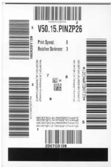
- See Figure 26 and Table 18. Inspect the test labels and determine which one has the best print quality for your application. If you have a bar code verifier, use it to measure bars/spaces and calculate the print contrast. If you do not have a bar code verifier, use your eyes or the system scanner to choose the optimal darkness setting based on the labels printed in this self test.
Figure 26 · Bar Code Darkness Comparison
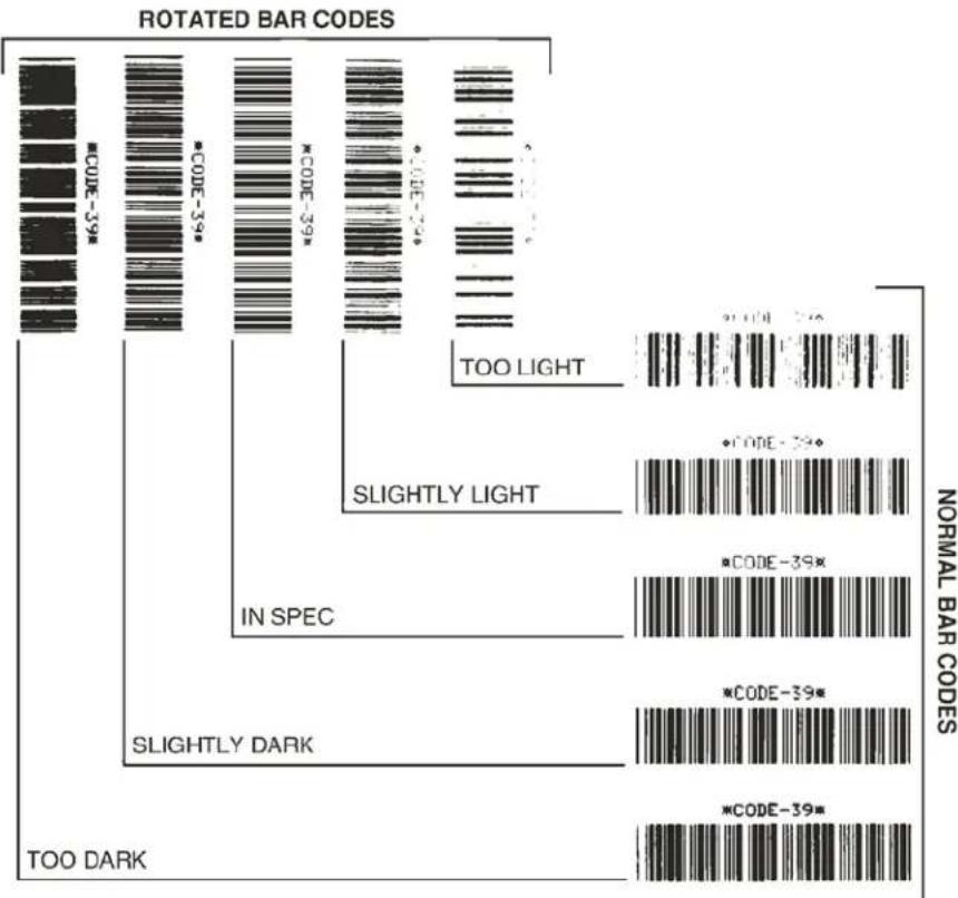
bar
| Rotation Bar Code | Count | | ----------------- | ----- | | COO-39-59 | 1 | | MCO-39 | 1 | | Slightly Dark | 1 | | TOO DARK | 1 |Table 18 · Judging Bar Code Quality
| Print Quality Description | |
| Too dark Labels that are too dark are fairly obvious. They may be readable but not “in-spec.”The normal bar code bars increase in size.The openings in small alphanumeric characters may fill in with ink.Rotated bar code bars and spaces run together. | |
| Slightly dark Slightly dark labels are not as obvious.The normal bar code will be “in-spec.”Small character alpha numerics will be bold and could be slightly filled in.The rotated bar code spaces are small when compared to the “in-spec” code, possibly making the code unreadable. | |
| “In-spec” The “in-spec” bar code can only be confirmed by a verifier,but it should exhibit some visible characteristics.The normal bar code will have complete, even bars and clear, distinct spaces.The rotated bar code will have complete, even bars and clear, distinct spaces. Although it may not look as good as a slightly dark bar code, the bar code will be “in-spec.”In both normal and rotated styles, small alphanumeric characters look complete. | |
| Slightly light Slightly light labels are, in some cases, preferred to slightly dark ones for “in-spec” bar codes.Both normal and rotated bar codes will be in spec, but small alphanumeric characters may not be complete. | |
| Too light Labels that are too light are obvious.Both normal and rotated bar codes have incomplete bars and spaces.Small alphanumeric characters are unreadable. |
- Note the relative darkness value and the print speed printed on the best test label.
- Add or subtract the relative darkness value from the darkness value specified on the configuration label. The resulting numeric value is the best darkness value for that specific label/ribbon combination and print speed.
- If necessary, change the darkness value to the darkness value on the best test label. See Adjust Print Darkness on page 91.
- If necessary, change the print speed to the same speed as on the best test label. See Adjust Print Speed on page 91.
FEED and PAUSE Self Test
Performing this self test temporarily resets the printer configuration to the factory default values. These values are active only until power is turned off unless you save them permanently in memory. If the factory default values are permanently saved, a media calibration procedure must be performed.
To perform a FEED and PAUSE self test, complete these steps:
- Turn off (O) the printer.
- Press and hold FEED and PAUSE while turning on (1) the printer.
- Hold FEED and PAUSE until the first control panel light turns off.
The printer configuration is temporarily reset to the factory default values. No labels print at the end of this test.
Communications Diagnostics Test
The communication diagnostics test is a troubleshooting tool for checking the interconnection between the printer and the host computer.
When the printer is in diagnostics mode, it prints all data received from the host computer as straight ASCII characters with the hex values below the ASCII text. The printer prints all characters received, including control codes such as CR (carriage return). Figure 27 shows a typical test label from this test.

Note • The test label prints upside-down.
Figure 27 · Communications Diagnostics Test Label
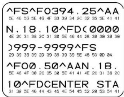
To use communications diagnostics mode, complete these steps:
-
Set the print width equal to or less than the label width being used for the test. See Set Print Width on page 94 for more information.
-
Set the printer to DIAGNOSTICS. For instructions, see Set Communications Mode on page 103.
The printer enters diagnostics mode and prints any data received from the host computer on a test label
- Check the test label for error codes. For any errors, check that your communication parameters are correct.
Errors show on the test label as follows:
• FE indicates a framing error.
- OE indicates an overrun error.
• PE indicates a parity error.
- NE indicates noise.
- Turn the printer off (O) and then back on (I) to exit this self test and return to normal operation.
Sensor Profile
Use the sensor profile label to troubleshoot the following types of problems:
- If the media sensor experiences difficulty in determining gaps (web) between labels.
- If the media sensor incorrectly identifies preprinted areas on a label as gaps (web).
For instructions on printing a sensor profile, see Print Sensor Profile on page 100. If the sensitivity of the sensors must be adjusted, perform Calibrate Media and Ribbon Sensor Sensitivity on page 101.
Ribbon Sensor Profile (Figure 28) The bars (1) on the sensor profile indicate the ribbon sensor readings. The ribbon sensor threshold setting is indicated by the word RIBBON (2). If the ribbon readings are below the threshold value, the printer does not acknowledge that ribbon is loaded.
Figure 28 • Sensor Profile (Ribbon Section)
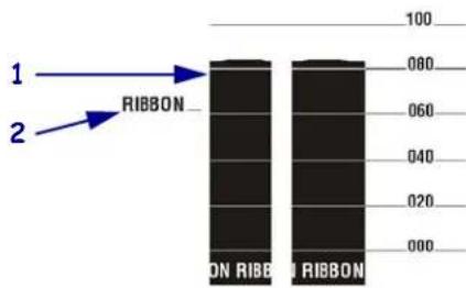
Media Sensor Profile (Figure 29) The media sensor readings are shown as bars and flat areas on the sensor profile. The bars (1) indicate gaps between labels (the web), and the low areas (2) indicate where labels are located. If you compare the sensor profile printout to a blank length of your media, the bars should be the same distance apart as the gaps on the media. If the distances are not the same, the printer may be having difficulty determining where the gaps are located.
The media sensor threshold settings are shown by the words MEDIA (3) for the media threshold and WEB (4) for the web threshold. Use the numbers to the left of the sensor readings to compare the numeric readings to the sensor settings.
Figure 29 · Sensor Profile (Media Section)
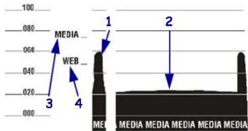
Specifications

natural_image
Abstract black and white pattern with curved white and black shapes (no text or symbols)This section provides the features of and specifications for this printer.
Contents
Features.... 156
Standard Features 156
Optional Features 156
Print Modes 156
Zebra Programming Language (ZPL) 157
Bar Codes 157
General Specifications 158
Physical Specifications. 158
Electrical Specifications 158
Environmental Conditions for Operation and Storage 158
Print Specifications by Model.... 159
Ribbon Specifications.... 161
Media Specifications 162
110Xi4 162
140Xi4, 170Xi4, and 220Xi4 Printers.... 163
Features
This section lists the standard and optional features for the printer.
Standard Features

Note • Printer specifications are subject to change without notice.
• Thermal transfer and direct thermal printing
• 16 MB SDRAM (12 MB user-available)
• USB 2.0 Port
• Real-time Clock
- Advanced Counter
- RS-232 serial port
- bidirectional parallel port
• U S B 2 . 0
- XML-enabled printing
Optional Features
• ZebraNet Internal Wireless Plus Print Server
• ZebraNet 10/100 Print Server (internal or external)
- ZebraNet PrintServer II (internal or external)
- IBM twinax/coax interfaces (internal)
• Full-width rotary knife cutter and catch tray
• Media rewind spindle
- Factory-installed 64 MB (61 MB user available) Flash memory option
- Additional fonts
Print Modes
Five different print modes can be used, depending on the printer options purchased:
- Tear-Off Mode: Labels are produced in strips.
- Peel-Off Mode: Labels are dispensed and peeled from the backing as needed.
- Cutter Mode: Labels are printed and individually cut.
- Applicator Mode: The printer is part of a larger label application system.
- Rewind Mode: Labels are rewound internally.
Zebra Programming Language (ZPL)
ZPL II features include:
- Downloadable graphics, scalable and bitmap fonts, and label formats
- Controlled via mainframe, mini-computer, PC, portable data terminal
- Object copying between memory areas
- Programmable quantity with print, pause, and cut control
• (RAM, memory card, and internal Flash)
- Communicates in printable ASCII characters
- Code page 850 character set • Error-checking protocol
- Data compression • Status message to host upon request
• Automatic virtual input buffer management
- Serialized fields
- Format inversion • In-spec OCR-A and OCR-B
- Mirror image printing • UPC/EAN
- Four-position field rotation (0°, 90°, 180°, 270°)
- User-programmable password
- S le w c o m m a n d
Bar Codes
Types of bar codes include:
• Bar code ratios—2:1, 7:3, 5:2, 3:1 • LOGMARS
- Codabar (supports ratios of 2:1 up to 3:1) • MaxiCode
• CODABLOCK
- Micro PDF
• C o d e 11
• M S I
• Code 39 (supports ratios of 2:1 up to 3:1)
• PDF-417 (2-dimensional bar code)
• Code 49 (two-dimensional bar code)
- PLANET code
• C o d e 9 3
- P l e s s e y
• Code 128 (with subsets A, B, and C and UCC case codes)
• POSTNET
- Check digit calculation where applicable
- QR-Code
- Data Matrix
- RSS code
• EAN-8, EAN-13, EAN extensions
- Standard 2 of 5
• ISBT-128
• TLC 39
- Industrial 2 of 5
• UPC-A, UPC-E, UPC extensions
- Interleaved 2 of 5 (supports ratios of 2:1 up to 3:1, Modulus 10 Check Digit)
General Specifications
Physical Specifications
Dimensions 110Xi4 140Xi4 170Xi4 220Xi4
| Height | 15.5 in (393.7 mm) | 15.5 in. (393.7 mm) | 15.5 in. (393.7 mm) | 15.5 in (393.7 mm) |
| Width | 10.31 in. (261.9 mm) | 11.31 in. (287.3 mm) | 13.31 in. (338.1 mm) | 15.81 in. (401.6 mm) |
| Depth | 20.38 in. (517.5 mm) | 20.38 in. (517.5 mm) | 20.38 in. (517.5 mm) | 20.38 in. (517.5 mm) |
| Weight without options | 50 lb. (22.7 kg) | 55 lb. (25 kg) | 67 lb. (30.5 kg) | 72 lb. (32.7 kg) |
Electrical Specifications
| Power | 110Xi4 140Xi4 170Xi4 220Xi4 | |||
| General | 90 to 264 VAC;48 to 62 Hz | 90 to 264 VAC;48 to 62 Hz | 90 to 264 VAC;48 to 62 Hz | 90 to 264 VAC;48 to 62 Hz |
| Power consumption printing PAUSE test at slowest speed | 121 W | 180 W | 220 W | 269 W |
| Printer idle | 20 W | 20 W | 20 W | 20 W |
Environmental Conditions for Operation and Storage
| Environment | Mode | Temperature | Relative Humidity |
| Operation | Thermal Transfer | 40° to 105°F(5° to 40°C) | 20 to 85% non-condensing |
| Direct Thermal | 32° to 105°F(0° to 40°C) | ||
| Storage | Thermal Transfer or Direct Thermal | -40° to 140°F(-40° to 60°C) | 5 to 85% non-condensing |
Print Specifications by Model
Refer to the key and the tables that follow for printer specifications.
Specifications Key
| ■ | Non-Continuous printing (gap, notch, or hole between labels). |
| ■ | Continuous printing (no gap, notch or hole). |
| ♦ | Ladder (rotated) orientation. |
| ♦ | Picket fence (nonrotated) orientation. |
110Xi4
| Print Specifications 110Xi4 200 dpi 110Xi4 300 dpi 110Xi4 600 dpi | |||
| Printhad resolution 203 dots/inch(8 dots/mm) | 300 dots/inch(12 dots/mm) | 600 dots/inch(24 dots/mm) | |
| Dot size(width×length) | 0.0049×0.0049 in.(0.125×0.125 mm) | 0.0033×0.0033 in.(0.084×0.084 mm) | 0.0016×0.0016 in.(0.042×0.042 mm) |
| First dot location (measured from inside media edge) | 0.10 ± 0.035 in.(2.5 ± 0.9 mm) | 0.023 ± 0.035 in.(0.6 ± 0.9 mm) | 0.023 ± 0.035 in.(0.6 ± 0.9 mm) |
| Maximum print width | 4.0 in. (102 mm) | 4.0 in. (102 mm) | 4.0 in. (102 mm) |
| Selectable print speeds (inches per second) | 2.4, 3, 4, 5, 6, 7, 8,9, 10, 11, 12, 13, 14 | 2.4, 3, 4, 5, 6, 7, 8,9, 10, 11, 12 | 1.5, 2, 3, 4, 5, 6 |
| Maximum Print length 39 in. (991 mm)■150 in. (3810 mm) ■ | 39 in. (991 mm)■100 in. (3810 mm) ■ | 39 in. (991 mm)■39 in. (991 mm) ■ | |
| Bar code modulus (X) dimension 4.9 mil to 49 mil◆4.9 mil to 49 mil◆ | 3.9 mil to 39 mil◆3.33 mil to 33 mil◆ | 1.6 mil to 16 mil◆1.6 mil to 16 mil◆ | |
| Thin film printhead with Element Energy Equalizer (E ^3 )® | Yes Yes Yes | ||
140Xi4, 170Xi4, and 220Xi4
| Print Specifications | 140Xi4 | 170Xi4 200 dpi | 170Xi4 300 dpi | 220Xi4 200 dpi | 220Xi4 300 dpi |
| Printhead resolution 203 dots/inch(8 dots/mm) | 203 dots/inch(8 dots/mm) | 300 dots/inch(12 dots/mm) | 203 dots/inch(8 dots/mm) | 300 dots/inch(12 dots/mm) | |
| Dot size (width×length) | 0.0049×0.0049 in.(0.125×0.125 mm) | 0.0049×0.0049 in.(0.125×0.125 mm) | 0.0033×0.0033 in.(0.084×0.084 mm) | 0.0049×0.0049 in.(0.125×0.125 mm) | 0.0033×0.0033 in.(0.084×0.084 mm) |
| First dot location(measured from insidemedia edge) | 0.10 ± 0.035 in.(2.5 ± 0.9 mm) | 0.10 ± 0.035 in.(2.5 ± 0.9 mm) | 0.10 ± 0.035 in.(2.5 ± 0.9 mm) | 0.10 ± 0.035 in.(2.5 ± 0.9 mm) | 0.10 ± 0.035 in.(2.5 ± 0.9 mm) |
| Maximum print width | 5.04 in. (128 mm) | 6.6 in. (168 mm) | 6.6 in. (168 mm) | 8.5 in. (216 mm) | 8.5 in. (216 mm) |
| Selectable Print Speeds(inches per second) | 2.4, 3, 4, 5, 6, 7, 8,9, 10, 11, 12, 13, 14 | 2.4, 3, 4, 5, 6, 7, 8, 9,10, 11, 12 | 2.4, 3, 4, 5, 6, 7, 8 | 2.4, 3, 4, 5, 6, 7, 8, 9,10 | 2.4, 3, 4, 5, 6 |
| Maximum print length | 39 in. (99 cm)■150 in. (381 cm) ■ | 39 in. (99 cm)■100 in. (254 cm) ■ | 39 in. (99 cm)■100 in. (254 cm) ■ | 39 in. (99 cm)■150 in. (381 cm) ■ | 39 in. (99 cm)■150 in. (381 cm) ■ |
| Bar code modulus (X) dimension | 4.9 mil to 49 mil◆4.9 mil to 49 mil◇ | 3.9 mil to 39 mil◆3.33 mil to 33 mil◇ | 3.9 mil to 39 mil◆3.33 mil to 33 mil◇ | 4.9 mil to 49 mil◆4.9 mil to 49 mil◇ | 4.9 mil to 49 mil◆4.9 mil to 49 mil◇ |
| Thin film printhead with Element Energy Equalizer(E3) | Yes | Yes | Yes | Yes | Yes |
Ribbon Specifications
Refer to the following tables for ribbon specifications.

Note • Consider the following when using ribbon:
- Match the ribbon to the label width and printhead width that you are using. The ribbon should be at least as wide as the labels to protect the printhead from excessive wear.
- Ribbon must be wound with the coated side out.
110Xi4
Ribbon Specifications 110Xi4 200 dpi 110Xi4 300 dpi 110Xi4 600 dpi
| Printhead resolution 203 dots/inch | (8 dots/mm) | 300 dots/inch(12 dots/mm) | 600 dots/inch(24 dots/mm) |
| Ribbon width Minimum | 0.79 in. (20 mm) | 0.79 in. (20 mm) | 0.79 in. (20 mm) |
| Ribbon width Maximum | 4.33 in. (110 mm) | 4.33 in. (110 mm) | 4.33 in. (110 mm) |
| Standard length with 2:1 label to ribbon ratio | 984 ft (300 m) | 984 ft (300 m) | 984 ft (300 m) |
| Standard length with 3:1 label to ribbon ratio | 1476 ft (450 m) | 1476 ft (450 m) | 1476 ft (450 m) |
| Ribbon core inside diameter | 1.0 in. (25.4 mm) | 1.0 in. (25.4 mm) | 1.0 in. (25.4 mm) |
| Maximum ribbon roll outside diameter | 3.2 in. (81.3 mm) | 3.2 in. (81.3 mm) | 3.2 in. (81.3 mm) |
140Xi4, 170Xi4, and 220Xi4
| Ribbon Specifications | 140Xi4 | 170Xi4 200 dpi | 170Xi4 300 dpi | 220Xi4 200 dpi | 220Xi4 300 dpi |
| Printhead resolution | 203 dots/inch(8 dots/mm) | 203 dots/inch(8 dots/mm) | 300 dots/inch(12 dots/mm) | 203 dots/inch(8 dots/mm) | 300 dots/inch(12 dots/mm) |
| Ribbon width Minimum | 1.57 in. (40 mm) | 2.0 in. (51 mm) | 2.0 in. (51 mm) | 4.25 in. (108 mm) | 4.25 in. (108 mm) |
| Ribbon width Maximum | 5.10 in. (130 mm) | 6.7 in. (170 mm) | 6.7 in. (170 mm) | 8.60 in. (220 mm) | 8.60 in. (220 mm) |
| Standard length with 2:1 label to ribbon ratio | 984 ft (300 m) | 984 ft (300 m) | 984 ft (300 m) | 984 ft (300 m) | 984 ft (300 m) |
| Standard length with 3:1 label to ribbon ratio | 1476 ft (450 m) | 1476 ft (450 m) | 1476 ft (450 m) | 1476 ft (450 m) | 1476 ft (450 m) |
| Ribbon core inside diameter | 1.0 in. (25.4 mm) | 1.0 in. (25.4 mm) | 1.0 in. (25.4 mm) | 1.0 in. (25.4 mm) | 1.0 in. (25.4 mm) |
| Maximum ribbon roll outside diameter | 3.2 in. (81.3 mm) | 3.2 in. (81.3 mm) | 3.2 in. (81.3 mm) | 3.2 in. (81.3 mm) | 3.2 in. (81.3 mm) |
Media Specifications
Use the correct size and type of labels for best performance. Refer to the tables that follow for specifications.

Important • Media registration and minimum label length are affected by label type and width, ribbon type, print speed, and printer mode of operation. Performance improves as these factors are optimized. Zebra recommends qualifying any application with thorough testing.
110Xi4
| Media Specifications | 110Xi4 200 dpi | 110Xi4 300 dpi | 110Xi4 600 dpi | |
| Minimum label length | Tear-Off | 0.7 in. (18 mm) | 0.7 in. (18 mm) | 0.7 in. (18 mm) |
| Peel-Off | 0.5 in. (13 mm) | 0.5 in. (13 mm) | 0.5 in. (13 mm) | |
| Cutter | 1.5 in. (38 mm) | 1.5 in. (38 mm) | 1.5 in. (38 mm) | |
| Rewind | 0.25 in. (6 mm) | 0.25 in. (6 mm) | 0.25 in. (6 mm) | |
| Total media width (label + backing, if any) | Minimum | 0.79 in. (20 mm) | 0.79 in. (20 mm) | 0.79 in. (20 mm) |
| Maximum | 4.5 in. (114 mm) | 4.5 in. (114 mm) | 4.5 in. (114 mm) | |
| Total thickness (includes backing, if any) | 0.003 in. (0.076 mm) | 0.003 in. (0.076 mm) | 0.003 in. (0.076 mm) | |
| 0.012 in. (0.305 mm) | 0.012 in. (0.305 mm) | 0.012 in. (0.305 mm) | ||
| Cutter maximum full-width media thickness | 0.009 in. (0.23 mm) | 0.009 in. (0.23 mm) | 0.009 in. (0.23 mm) | |
| Roll media core inside diameter | 3 in. (76 mm) | 3 in. (76 mm) | 3 in. (76 mm) | |
| Maximum roll diameter on 3 in. (76 mm) core | 8.0 in. (203 mm) | 8.0 in. (203 mm) | 8.0 in. (203 mm) | |
| Interlabel gap | Minimum | 0.079 in. (2 mm) | 0.079 in. (2 mm) | 0.079 in. (2 mm) |
| Preferred | 0.118 in. (3 mm) | 0.118 in. (3 mm) | 0.118 in. (3 mm) | |
| Maximum No more than the calibrated length of the label. | No more than the calibrated length of the label. | No more than the calibrated length of the label. | ||
| Maximum internal fanfold media pack size (label + backing): L × W×H | 8.0×4.5×4.5 in.(203×114×114 mm) | 8.0×4.5×4.5 in.(203×114×114 mm) | 8.0×4.5×4.5 in.(203×114×114 mm) | |
| Ticket/tag sensing notch: L × W | 0.12×0.25 in. (3×6 mm) | 0.12×0.25 in. (3×6 mm) | 0.12×0.25 in. (3×6 mm) | |
| Ticket/tag sensing hole diameter | 0.125 in. (3 mm) | 0.125 in. (3 mm) | 0.125 in. (3 mm) | |
| Label registration tolerance (vertical) | ± 0.06 in. (± 1.5 mm) | ± 0.06 in. (± 1.5 mm) | ± 0.06 in. (± 1.5 mm) | |
| Label registration tolerance (horizontal) | ± 0.06 in. (± 1.5 mm) | ± 0.06 in. (± 1.5 mm) | ± 0.06 in. (± 1.5 mm) | |
110Xi4 Black Mark Sensing Only
| Media Specifications | 110Xi4 200 dpi | 110Xi4 300 dpi | 110Xi4 600 dpi |
| Mark length (measuring parallel to label/tag edge) | Minimum 0.12 in. (3 mm) 0.12 in. (3 mm) 0.12 in. (3 mm) | ||
| Maximum 0.43 in. (11 mm) 0.43 in. (11 mm) 0.43 in. (11 mm) | |||
| Mark width (measuring to perpendicular label/tag edge) | Minimum 0.43 in. (11 mm) 0.43 in. (11 mm) 0.43 in. (11 mm) | ||
| Maximum Full media width Full media width Full media width | |||
| Mark location | within 0.040 in. (1 mm) of the inside media edge | within 0.040 in. (1 mm) of the inside media edge | within 0.040 in. (1 mm) of the inside media edge |
| Mark density in Optical Density Unit (ODU) | >1.0 | >1.0 | >1.0 |
140Xi4, 170Xi4, and 220Xi4 Printers
| Media Specifications 140Xi4 | 170Xi4 | 220Xi4 | ||
| Minimum label length | Tcar-Off | 0.7 in. (18 mm) | 0.7 in. (18 mm) | 0.7 in. (18 mm) |
| Peel-Off | 0.5 in. (13 mm) | 0.5 in. (13 mm) | 0.5 in. (13 mm) | |
| Cutter | 1.5 in. (38 mm) | 1.5 in. (38 mm) | 1.5 in. (38 mm) | |
| Rewind | 0.25 in. (6 mm) | 0.25 in. (6 mm) | 0.25 in. (6 mm) | |
| Total media width (label + backing, if any) | Minimum | 1.57 in. (40 mm) | 2.00 in. (51 mm) | 4.25 in. (108 mm) |
| Maximum | 5.51 in. (140 mm) | 7.1 in. (180 mm) | 8.80 in. (224 mm) | |
| Total thickness (includes backing, if any) | Minimum | 0.003 in. (0.076 mm) | 0.003 in. (0.076 mm) | 0.003 in. (0.076 mm) |
| Maximum | 0.012 in. (0.305 mm) | 0.012 in. (0.305 mm) | 0.012 in. (0.305 mm) | |
| Cutter maximum full-width media thickness | 0.009 in. (0.23 mm) | 0.007 in. (0.18 mm) | 0.005 in. (0.14 mm) | |
| Roll media core inside diameter | 3 in. (76 mm) | 3 in. (76 mm) | 3 in. (76 mm) | |
| Maximum roll diameter on 3 in. (76 mm) core | 8.0 in. (203 mm) | 8.0 in. (203 mm) | 8.0 in. (203 mm) | |
| Interlabel gap | Minimum | 0.079 in. (2 mm) | 0.079 in. (2 mm) | 0.079 in. (2 mm) |
| Preferred | 0.118 in. (3 mm) | 0.118 in. (3 mm) | 0.118 in. (3 mm) | |
| Maximum No more than the calibrated length of the label. | No more than the calibrated length of the label.* | No more than the calibrated length of the label. | ||
| Maximum internal fanfold media pack size (label + backing): L×W×H | 8.0×5.5×4.5 in. (203×140×114 mm) | 8.0×7.1×4.5 in. (203×180×114 mm) | 8.0×8.8×4.5 in. (203×224×114 mm) | |
| Ticket/tag sensing notch: L×W | 0.12×0.25 in. (3×6 mm) | 0.12×0.25 in. (3×6 mm) | 0.12×0.25 in. (3×6 mm) | |
| Ticket/tag sensing hole diameter | 0.125 in. (3 mm) | 0.125 in. (3 mm) | 0.125 in. (3 mm) | |
| Effective leading edge registration accuracy (vertical) | ± 0.070 in. (± 1.8 mm) | ± 0.070 in. (± 1.8 mm) | ± 0.060 in. (± 1.5 mm) | |
| Effective leading edge registration accuracy (horizontal) | ± 0.070 in. (± 1.8 mm) | ± 0.070 in. (± 1.8 mm) | ± 0.060 in. (± 1.5 mm) | |
140Xi4, 170Xi4, and 220Xi4 Black Mark Sensing Only
| Media Specifications 140Xi4 170Xi4 220Xi4 | ||||
| Mark length (measuring parallel to label or tag edge) | Minimum | 0.12 in. (3 mm) | 0.12 in. (3 mm) | 0.12 in. (3 mm) |
| Maximum | 0.43 in. (11 mm) | 0.43 in. (11 mm) | 0.43 in. (11 mm) | |
| Mark width (measuring to perpendicular label or tag edge) | Minimum | 0.43 in. (11 mm) | 0.43 in. (11 mm) | 0.43 in. (11 mm) |
| Maximum Full media width Full media width Full media width | ||||
| Mark location within 0.040 in. (1 mm) of the inside media edge | within 0.040 in. (1 mm) of the inside media edge | within 0.040 in. (1 mm) of the inside media edge | ||
| Mark density in Optical Density Unit (ODU) >1.0 | >1.0 | >1.0 | ||
End User License Agreement

natural_image
Abstract black and white pattern with curved white and black shapes (no text or symbols)Please read the terms of this “End User License Agreement” (the “Agreement”) carefully. The Agreement is a legal agreement between you (either an individual or a single entity) and Zebra Technologies International, LLC (“Zebra”) for the Zebra computer software and/or firmware accompanying this End User License Agreement, and any associated media, printed materials and any “online” or electronic documentation (collectively, “Software”). By installing or using the Software, you agree to be bound by the terms of this Agreement. If you do not agree to the terms of this Agreement, you may not install or use the Software.
-
Grant of License. The Software is protected by copyright and other intellectual property laws and international treaties. The Software is licensed to you, and not sold, subject to the terms of this Agreement. Subject to the terms of this Agreement, Zebra hereby grants you a limited, personal, non-exclusive license during the term of this Agreement to use the Software solely and exclusively for your internal use for the operation of your associated Zebra printer(s) and for no other purpose. To the extent that any portion of the Software is provided to you in a manner that is designed to be installed by you, you may install one copy of the installable Software on one hard disk or other storage device for one printer, computer, workstation, terminal, or other digital electronic device, as applicable (an “Electronic Device”), and you may access and use that Software as installed on that Electronic Device so long as only one copy of such Software is in operation. If you are an organization rather than an individual, you may authorize personnel associated with your business to use the Software, but only one person at a time on one Electronic Device at a time. You agree not to duplicate or copy the Software, except that you may make one back-up copy for archive purposes. The primary user of the Electronic Device on which installable Software is installed may also make a copy for his or her exclusive use on a portable computer, so long as such Software is being used only on one Electronic Device at a time.
-
Storage/Network Use. In the alternative, you may install a copy of the Software on a storage device, such as a network server, used only to access and use the Software on your Electronic Devices over an internal network; however, you must acquire and dedicate a license for each separate Electronic Device on which the Software is accessed and used from the storage device. A license for the Software may not be shared or used concurrently on different Electronic Devices.
-
Documentation. If the Software contains documentation which is provided only in electronic form, you may print one copy of such electronic documentation. You may not copy the printed materials accompanying the Software.
-
Limitations of Reverse Engineering, Decompilation and Disassembly. You may not reverse engineer, decompile, or disassemble the Software, except and only to the extent that such activity is permitted by applicable law notwithstanding this limitation.
-
Transfer/Sublicense. You may not transfer, sublicense, distribute, rent, lease, supply, market or lend the Software to any other party.
-
Confidentiality. You acknowledge that the Software embodies confidential information owned by Zebra and/or its suppliers and licensors. To the extent you have access to any such information, you agree to use such information only for the authorized use of the Software. You further agree not to disclose such confidential information to any other party and to use at least the same degree of care to maintain the confidential nature of such information as you use to maintain the confidentiality of your own confidential information.
-
Intellectual Property. All title, copyrights and other intellectual property rights in and to the Software (including but not limited to copyrights, patents, trade secrets and trademarks) are owned by Zebra or its suppliers and licensors. You must maintain all copyright notices on all copies of the Software. All rights not expressly granted are reserved by Zebra. Without prejudice to any rights or remedies Zebra may have for your violation of this Software License, Zebra shall own all changes or modifications to the Software.
-
Termination. Without prejudice to any other rights or remedies Zebra may have, Zebra may terminate this Agreement if you fail to comply with the terms and conditions of this Agreement. Zebra may terminate this Agreement by offering you a superseding Agreement for the Software or any replacement or modified version of or upgrade to the Software and conditioning your continued use of the Software or such replacement, modified or upgraded version on your acceptance of such superseding Agreement. In addition, either party may terminate this Agreement at any time. Subject to the foregoing, termination shall be effective upon notice to the other party. In the event that this Agreement terminates for any reason, your license to use the Software will terminate, and you must immediately stop using the Software, destroy all copies of the Software and all of its component parts, and, upon request, provide an affidavit certifying your compliance with the foregoing. The provisions of Sections 4, 5, 6, 7, 12, 13, 14, 15, 16, 17, 18, 19 and 20 shall survive termination of this Agreement.
-
U.S. Government Restricted Rights. You agree that the Software constitutes “commercial computer software” and/or “commercial computer software documentation” within the meaning of Federal Acquisition Regulation § 12.212 for civilian agencies and Defense Federal Acquisition Regulation Supplement § 227.7202. Accordingly, if you are an agency, department, employee, or other entity of the United States Government, the use, duplication, reproduction, release, modification, disclosure, or transfer of the Software, including technical data or manuals, is restricted by the terms, conditions and covenants contained in these EULA Terms and Conditions. All Software provided to the U.S. Government pursuant to solicitations issued prior to December 1, 1995 is provided with RESTRICTED RIGHTS as provided for in FAR, 48 CFR 52.227-19 (JUNE 1987) or DFARs, 48 CFR 252.227-7013 (OCT 1988), as applicable.
-
Export Restrictions. You agree that you will not export or re-export the Software, any part thereof, or any process or service that is the direct product of the Software (the foregoing collectively referred to as the “Restricted Components”), to any country, person or entity subject to U.S. export restrictions. You specifically agree not to export or re-export any of the Restricted Components: (i) to any country to which the U.S. has embargoed or restricted the export of goods or services, which currently include but are not necessarily limited to Cuba, Iran, Iraq, North Korea, Sudan and Syria, or to any national of any such country, wherever located, who intends to transmit or transport the Restricted Components back to such country; (ii) to any person or entity who you know or have reason to know will utilize the Restricted Components in the design, development or production of nuclear, chemical or biological weapons; or (iii) to any person or entity who has been prohibited from participating in U.S. export transactions by any federal agency of the U.S. government. You warrant and represent that neither the U.S. Commerce Department, Bureau of Export Administration nor any other U.S. federal agency has suspended, revoked or denied your export privileges. Contractor/Manufacturer is Zebra Technologies Corporation, 333 Corporate Woods Parkway, Vernon Hills, Illinois 60061.
-
Accessing Services Using the Software. Your use of any service accessible using the Software is not covered by this EULA and may be governed by separate terms of use, conditions or notices. Zebra and its suppliers and licensors hereby disclaim any such liability for any such services accessed.
-
Your Security Responsibilities. Notwithstanding anything to the contrary in this Agreement, as between Zebra and you, you acknowledge and agree that you are solely responsible for maintaining and protecting all aspects of any network, systems, and data (including any Personal Information) of, relating to, possessed by, or maintained by you, including maintaining and protecting such things from or against any theft, loss, misuse, alteration, disposal, or unauthorized access. “Personal Information” means individually identifiable information from or about an individual consumer including, but not limited to: (a) a first and last name or first initial and last name; (b) a home or other physical address, which includes at least a street name and name of city or town; (c) an email address; (d) a telephone number; (e) a Social Security number; (f) credit and/or debit card information, including number, expiration date, security code, and/or track data; (g) date of birth; (h) driver's license number; or (i) any other information from or about an individual consumer that is combined with (a) though (i) above.
-
Disclaimer. ZEBRA SUPPLIES THE SOFTWARE AS IS AND WITH ALL FAULTS AND DOES NOT MAKE ANY WARRANTIES WHATSOEVER, EXPRESS OR IMPLIED, INCLUDING BUT NOT LIMITED TO WARRANTIES CONCERNING THE SOFTWARE OR ANY APPLICATION, OPERATION OR USE THEREOF, THE OUTPUT OR THE DATA GENERATED BY THE OPERATION OR USE THEREOF, OR ANY SUPPORT SERVICES RENDERED WITH RESPECT THERETO. ZEBRA HEREBY EXCLUDES ALL IMPLIED WARRANTIES TO THE MAXIMUM EXTENT AUTHORIZED BY LAW, INCLUDING, SPECIFICALLY, ANY IMPLIED WARRANTY ARISING BY STATUTE OR OTHERWISE IN LAW OR FROM A COURSE OF DEALING OR USAGE OF TRADE, ALL IMPLIED WARRANTIES OF MERCHANTABILITY, OR OF MERCHANTABILITY QUALITY, OR OF FITNESS FOR ANY PURPOSE, PARTICULAR, SPECIFIC OR OTHERWISE, OR OF TITLE, OR OF NONINFRINGEMENT. SOME JURISDICTIONS DO NOT ALLOW THE EXCLUSION OR LIMITATION OF IMPLIED WARRANTIES, SO THE ABOVE LIMITATION OR EXCLUSION MAY NOT APPLY TO YOU. WHEN THE
IMPLIED WARRANTIES ARE NOT ALLOWED TO BE EXCLUDED IN THEIR ENTIRETY, THEY WILL BE LIMITED TO THE DURATION OF NINETY (90) DAYS. WITHOUT LIMITING THE GENERALITY OF THE FOREGOING, ZEBRA DOES NOT WARRANT THAT THE OPERATION OF THE SOFTWARE WILL BE UNINTERRUPTED OR ERROR FREE. To the extent that the Software covered by this EULA includes emulation libraries, such emulation libraries do not work 100% correctly or cover 100% of the functionality of the printer language being emulated, are offered “as is” AND WITH ALL FAULTS, AND ALL THE DISCLAIMERS AND LIMITATIONS CONTAINED IN THIS PARAGRAPH AND THIS AGREEMENT APPLY TO SUCH EMULATION LIBRARIES.
-
Limitation of Liability and Damages. ZEBRA DOES NOT ASSUME RESPONSIBILITY FOR ANY SPECIFIC APPLICATION OF THE SOFTWARE OR FOR COMPATIBILITY WITH OTHER SOFTWARE OR EQUIPMENT. TO THE FULL EXTENT ALLOWED BY LAW, ZEBRA EXCLUDES FOR ITSELF AND ITS LICENSORS AND SUPPLIERS ANY LIABILITY FOR ANY DAMAGES, INCLUDING WITHOUT LIMITATION DIRECT, CONSEQUENTIAL, INCIDENTAL, INDIRECT, SPECIAL, EXEMPLARY OR PUNITIVE DAMAGES OF ANY KIND, OR FOR LOSS OF REVENUE OR PROFITS, LOSS OF BUSINESS, DAMAGE TO GOODWILL, LOSS OF INFORMATION OR DATA, OR OTHER FINANCIAL LOSS ARISING OUT OF OR IN CONNECTION WITH THE SALE, INSTALLATION, MAINTENANCE, USE, PERFORMANCE, FAILURE, OR INTERRUPTION OF ANY PRODUCTS, PARTS OR SOFTWARE, WHETHER BASED ON CONTRACT, TORT, NEGLIGENCE, STRICT LIABILITY OR OTHERWISE, EVEN IF ZEBRA OR ANY LICENSOR OR SUPPLIER HAS BEEN ADVISED OF THE POSSIBILITY OF SUCH DAMAGES. TO THE MAXIMUM EXTENT AUTHORIZED BY LAW, THIS DISCLAIMER OF LIABILITY FOR DAMAGES WILL NOT BE AFFECTED IF ANY REMEDY PROVIDED HEREIN SHALL FAIL OF ITS ESSENTIAL PURPOSE. SOME JURISDICTIONS DO NOT ALLOW THE EXCLUSION OR LIMITATION OF DIRECT, INCIDENTAL, CONSEQUENTIAL OR OTHER DAMAGES, SO THE ABOVE LIMITATION OR EXCLUSION MAY NOT APPLY TO YOU. WHEN LIABILITY FOR DAMAGES IS NOT ALLOWED TO BE LIMITED OR EXCLUDED IN ITS ENTIRETY, ZEBRA LIMITS ITS LIABILITY TO REPAIR, REPLACEMENT, OR, AT ZEBRA'S OPTION, REFUND OF THE PRICE OF THE SOFTWARE. NOTWITHSTANDING ANYTHING TO THE CONTRARY IN THIS AGREEMENT, ZEBRA SHALL NOT, UNDER ANY CIRCUMSTANCE OR UNDER ANY LEGAL OR EQUITABLE THEORY (INCLUDING, WITHOUT LIMITATION, UNDER CONTRACT, TORT, CONTRIBUTION, OR INDEMNITY), BE LIABLE TO CUSTOMER OR TO ANY OTHER PARTY FOR ANY LOSSES, DAMAGES (WHETHER DIRECT, INDIRECT, SPECIAL, PUNITIVE, INCIDENTAL OR CONSEQUENTIAL), COSTS, EXPENSES, FINES OR FEES RELATING TO THE THEFT, LOSS, MISUSE, ALTERATION, OR DISPOSAL OF, OR UNAUTHORIZED ACCESS TO, ANY NETWORK, SYSTEM, OR DATA (INCLUDING PERSONAL INFORMATION) OF, RELATING TO, POSSESSED BY, OR MAINTAINED BY CUSTOMER.
-
Zebra Suppliers and Licensors. Any release, disclaimer or limitation of Zebra's liability or damages pursuant to this Agreement shall be construed, in addition to Zebra's benefit, also to the benefit of Zebra's suppliers, licensors, employees, and contractors and, without limiting any other defenses that such suppliers, licensors, employees and contractors may have, you agree to release such parties from liability or damages in accordance with such release, disclaimer, or limitation of liability or damages to the same extent that such provisions apply to Zebra.
-
Governing Law. To the maximum extent permitted by law, the laws of the State of Illinois, U.S.A., without reference to its conflict of laws provisions, will apply to this Agreement. You irrevocably agree to submit to the exclusive jurisdiction and venue of the state or federal courts in the State of Illinois in the event of any litigation involving this Agreement or the Software. You agree that you shall not assert any claim that you are not subject to the jurisdiction of such courts, that the venue is improper, that the forum is inconvenient or any similar objection, claim or argument. Zebra may, in its sole discretion, choose to resolve any controversy or dispute between you and Zebra concerning this Agreement, or the existence, validity, breach or termination thereof, whether during or after the term by binding arbitration in accordance with the Commercial Arbitration Rules of the American Arbitration Association (“AAA”), as modified or supplemented under this Section 15, by providing notice to you. In the event that Zebra provides such notice, you hereby waive any right to institute a court or other dispute resolution proceeding with respect to such controversy or dispute and acknowledge arbitration in accordance with this Section 15 as the sole and exclusive means of resolving such controversy or dispute. The arbitration proceeding will take place in Chicago, Illinois and be conducted in the English language. The arbitration panel will consist of 3 arbitrators, one arbitrator appointed by each party and a third neutral arbitrator appointed by the two arbitrators designated by the parties. Any communication between a party and any arbitrator will be directed to the AAA for transmittal to the arbitrator. The parties expressly agree that the arbitrators will be empowered to, at either party’s request, grant injunctive relief. The arbitral award will be the exclusive remedy of the parties for all claims, counterclaims, issues or accountings presented or pleaded to the arbitrators. Judgment upon the arbitral award may be entered in any court that has jurisdiction thereof. Any additional costs, fees or expenses incurred in enforcing the arbitral award will be charged against the party that resists its enforcement. Nothing in this Section will prevent Zebra from seeking interim injunctive relief against you or filing an action against you to collect unpaid and past due amounts in any court of competent jurisdiction.
-
Injunctive Relief. You acknowledge that, in the event you breach any provision of this Agreement, Zebra will not have an adequate remedy in money or damages. Zebra shall therefore be entitled to obtain an injunction against such breach from any court of competent jurisdiction immediately upon request without posting bond. Zebra's right to obtain injunctive relief shall not limit its right to seek further remedies.
- Entire Agreement. This Agreement constitutes the entire understanding and agreement of the parties and supersedes any and all prior or contemporaneous representations, understandings and agreements between the parties with respect to the subject matter of this Agreement. If any provision of this Agreement is held invalid, the remainder of this Agreement shall continue in full force and effect.
- Assignment. You may not assign this Agreement or any of your rights or obligations hereunder (by operation of law or otherwise) without the prior written consent of Zebra. Zebra may assign this Agreement and its rights and obligations without your consent. Subject to the foregoing, this Agreement shall be binding upon and inure to the benefit of the parties to it and their respective legal representatives, successors and permitted assigns.
- Modification. No modification of this Agreement shall be binding unless it is in writing and is signed by an authorized representative of the party against whom enforcement of the modification is sought.
-
Waiver. The failure by a party to exercise any right hereunder shall not operate as a waiver of such party's right to exercise such right or any other right in the future.
-
QUESTIONS. Should you have any questions, or if you desire to contact Zebra for any reason, please contact the Zebra subsidiary serving your country, or write:
Zebra Technologies International, LLC
333 Corporate Woods Parkway
Vernon Hills, Illinois 60061
REVISED MARCH 2008.
Glossary

natural_image
Abstract black and white pattern with curved white lines on black background (no text or symbols)alphanumeric Indicating letters, numerals, and characters such as punctuation marks.
backfeed When the printer pulls the media and ribbon (if used) backward into the printer so that the beginning of the label to be printed is properly positioned behind the printhead. Backfeed occurs when operating the printer in Tear-Off and Applicator modes.
bar code A code by which alphanumeric characters can be represented by a series of adjacent stripes of different widths. Many different code schemes exist, such as the universal product code (UPC) or Code 39.
black mark A registration mark found on the underside of the print media that acts as a start-of-label indication for the printer. (See non-continuous media.)
calibration (of a printer) A process in which the printer determines some basic information needed to print accurately with a particular media and ribbon combination. To do this, the printer feeds some media and ribbon (if used) through the printer and senses whether to use the direct thermal or thermal transfer print method, and (if using non-continuous media) the length of individual labels or tags.
character set The set of all letters, numerals, punctuation marks, and other characters that can be expressed by a particular font or bar code.
character shaping Characters assume different glyphic forms depending on the context. They can be used with a script-based language.
check digit A character added to a bar code symbol that indicates to the scanner that it has read the symbol correctly.
configuration The printer configuration is a group of operating parameters specific to the printer application. Some parameters are user selectable, while others are dependent on the installed options and mode of operation. Parameters may be switch selectable, control panel programmable, or downloaded as ZPL II commands. A configuration label listing all the current printer parameters may be printed for reference.
continuous media Label or tag-stock media that has no notch, gap, or web (media liner only) to separate the labels or tags. The media is one long piece of material.
core diameter The inside diameter of the cardboard core at the center of a roll of media or ribbon.
diagnostics Information about which printer functions are not working that is used for troubleshooting printer problems.
die-cut media A type of label stock that has individual labels stuck to a media liner. The labels may be either lined up against each other or separated by a small distance. Typically the material surrounding the labels has been removed. (See non-continuous media.)
direct thermal A printing method in which the printhead presses directly against the media. Heating the printhead elements causes a discoloration of the heat-sensitive coating on the media. By selectively heating the printhead elements as the media moves past, an image is printed onto the media. No ribbon is used with this printing method. Contrast this with thermal transfer.
direct thermal media Media that is coated with a substance that reacts to the application of direct heat from the printhead to produce an image.
dynamic RAM The memory devices used to store the label formats in electronic form while they are being printed. The amount of DRAM memory available in the printer determines the maximum size and number of label formats that can be printed. This is volatile memory that loses the stored information when power is turned off.
fanfold media Media that comes folded in a rectangular stack. Contrast this with roll media.
firmware This is the term used to specify the printer's operating program. This program is downloaded to the printer from a host computer and stored in FLASH memory. Each time the printer power is turned on, this operating program starts. This program controls when to feed the media forward or backward and when to print a dot on the label stock.
FLASH memory FLASH memory is non-volatile and maintains the stored information intact when power is off. This memory area is used to store the printer's operating program. In addition, this memory can be used to store optional printer fonts, graphic formats, and complete label formats.
Font A complete set of alphanumeric characters in one style of type. Examples include CG Times™, CG Triumvirate Bold Condensed™.
inlay An RFID transponder.
integrated circuit (IC) chip The part of an RFID transponder that contains the RF circuit, coders, decoders, and memory.
ips (inches-per-second) The speed at which the label or tag is printed. Zebra printers can print from 1 ips to 12 ips.
label An adhesive-backed piece of paper, plastic, or other material on which information is printed.
label backing (liner) The material on which labels are affixed during manufacture and which is discarded or recycled by the end-users.
light emitting diode (LED) Indicators of specific printer status conditions. Each LED is either off, on, or blinking depending on the feature being monitored.
liquid crystal display (LCD) The LCD is a back-lit display that provides the user with either operating status during normal operation or option menus when configuring the printer to a specific application.
lock-up This is the term generally used to describe a fault condition that, for no apparent reason, causes the printer to stop working.
media Material onto which data is printed by the printer. Types of media include: tag stock, die-cut labels, continuous labels (with and without media liner), non-continuous media, fanfold media, and roll media.
media sensor This sensor is located behind the printhead to detect the presence of media and, for non-continuous media, the position of the web, hole, or notch used to indicate the start of each label.
media supply hanger The stationary arm that supports the media roll.
non-continuous media Media that contains an indication of where one label/printed format ends and the next one begins. Examples are die-cut labels, notched tag-stock, and stock with black mark registration marks.
non-volatile memory Electronic memory that retains data even when the power to the printer is turned off.
notched media A type of tag stock containing a cutout area that can be sensed as a start-of-label indicator by the printer. This is typically a heavier, cardboard-like material that is either cut or torn away from the next tag. (See non-continuous media.)
peel-off A mode of operation in which the printer peels a printed label away from the backing and allows the user to remove it before another label is printed. Printing pauses until the label is removed.
print speed The speed at which printing occurs. For thermal transfer printers, this speed is expressed in terms of ips (inches per second).
printhead wear The degradation of the surface of the printhead and/or the print elements over time. Heat and abrasion can cause printhead wear. Therefore, to maximize the life of the printhead, use the lowest print darkness setting (sometimes called burn temperature or head temperature) and the lowest printhead pressure necessary to produce good print quality. In the thermal transfer printing method, use ribbon that is as wide or wider than the media to protect the printhead from the rough media surface.
registration Alignment of printing with respect to the top (vertical) or sides (horizontal) of a label or tag.
ribbon A band of material consisting of a base film coated with wax or resin “ink.” The inked side of the material is pressed by the printhead against the media. The ribbon transfers ink onto the media when heated by the small elements within the printhead. Zebra ribbons have a coating on the back that protects the printhead from wear.
ribbon wrinkle A wrinkling of the ribbon caused by improper alignment or improper printhead pressure. This wrinkle can cause voids in the print and/or the used ribbon to rewind unevenly. This condition should be corrected by performing adjustment procedures.
roll media Media that comes supplied rolled onto a core (usually cardboard). Contrast this with fanfold media.
supplies A general term for media and ribbon.
symbology The term generally used when referring to a bar code.
tag A type of media having no adhesive backing but featuring a hole or notch by which the tag can be hung on something. Tags are usually made of cardboard or other durable material.
tear-off A mode of operation in which the user tears the label or tag stock away from the remaining media by hand.
thermal transfer A printing method in which the printhead presses an ink or resin coated ribbon against the media. Heating the printhead elements causes the ink or resin to transfer onto the media. By selectively heating the printhead elements as the media and ribbon move past, an image is printed onto the media. Contrast this with direct thermal.
Index

natural_image
Abstract black and white pattern with curved white lines on black background (no text or symbols)Numerics
110Xi4
black mark specifications, 163
label specifications, 162
print specifications, 159
ribbon specifications, 161
140Xi4
black mark specifications, 164
label specifications, 163
print specifications, 160
ribbon specifications, 161
170Xi4
black mark specifications, 164
label specifications, 163
print specifications, 160
ribbon specifications, 161
220Xi4
label specifications, 163
print specifications, 160
ribbon specifications, 161
black mark specifications, 164
A
adhesive test for ribbon coating, 34
adjustments
left position, 107
lower media sensor, 80
media sensors, 77
print darkness, 91
printhead toggle pressure, 81
tear-off position, 92
applicator port setting, 108
auto-calibration, 75
B
backfeed setting, 106
backing removal, 66
bar codes
list available codes, 98
types of codes, 157
battery disposal, 116
baud setting, 102
before you begin setup, 20
bitmap scaling factor, 111
black mark media
described, 32
setting sensor type, 93
when to clean sensor, 117
C
CALIBRATE button function, 18
calibration
CALIBRATE button, 18
media and ribbon sensor, 101
methods, 75
setting for head close, 106
setting for media power up, 105
troubleshooting problems, 141
Canadian DOC compliance, 4
CANCEL button
CANCEL self test, 147
function, 18
checklist
before you begin, 20
troubleshooting, 130
cleaning
cutter, 125
exterior of printer, 117
media compartment, 117
printhead and platen roller, 118
recommended schedule, 117
sensors, 121
snap plate, 124
coax option
characteristics of coax connection, 23
connection and configuration, 26
communication interfaces, 23
communications diagnostics test
overview, 153
selecting, 103
communications problems, 142
configuration
changing parameters, 91
enter and use Setup mode, 86
exit Setup mode, 87
software or printer driver, 91
configuration label
printing using CANCEL self test, 147
printing using List Setup command, 98
conformity declaration, 3
connect printer to computer or network, 24
connect printer to power source, 28
contacts, 11
continuous media
described, 32
setting media type, 93
control panel
buttons, 18
enter and use Setup mode, 86
exit Setup mode, 87
illustration, 17
keypad cover, 30
LCD error messages, 131
LCD functions, 18
location, 16
parameters, 91
control prefix setting, 104
counters, 98
customer service, 11
cutter
cleaning, 125
Cutter mode media path, 38
print mode use described, 36
selecting Cutter mode, 93
when to clean, 117
D
darkness setting, 91
data bits setting, 102
data cables, 24
data source
connections, 23
site selection, 22
date setting, 111
declaration of conformity, 3
default password, 88
defragmenting message, 135
Delayed Cut mode
print mode use described, 36
selecting, 93
delimiter character setting, 104
diagnostics, 146
direct thermal mode
media scratch test, 33
setting, 94
disable password protection, 88
display language
changing from unreadable language, 144
selection, 112
disposal of printer parts, 116
dpi format conversion, 111
E
electrical specifications, 158
electronics cover, 16
end user license agreement, 165
enter Setup mode, 86
environmental specifications, 158
error messages, 131
Error mode, 18
Ethernet
characteristics of internal wired connection, 23
characteristics of wireless connection, 23
internal wired connection and configuration, 27
wireless connection and configuration, 27
exit Setup mode, 87
exterior cleaning, 117
external view of printer, 16
F
factory defaults
reload parameters, 87
restore network settings, 87
fanfold media
described, 32
FCC compliance, 4
features, 156
FEED button
FEED and PAUSE self test, 152
FEED self test, 149
function, 18
Flash memory, 99
font list, 98
format convert setting, 111
format list, 98
format prefix setting, 104
H
head test setting, 107
host handshake setting, 103
humidity requirements, 22
|
idle display setting, 111
images list, 98
initialize Flash memory, 99
inspect for shipping damage, 21
international safety organization marks, 29
L
label backing removal, 66
label length maximum setting, 95
label specifications, 162
label top
printer cannot detect, 145
setting, 106
label-available sensor
location, 121
when to clean, 117
labels did not print, 142
language
changing from unreadable language, 144
selection, 112
LCD messages
error messages, 131
language selection, 112
Setup mode, 91
liability, 2
license agreement, 165
list settings
all settings, 99
bar codes, 98
fonts, 98
formats, 98
images, 98
network, 99
setup, 98
load factory defaults, 87
loading
ribbon, 68
long calibration, 75
lower media sensor adjustment, 80
lubrication, 116
M
mark LED setting, 110
Mark Med S. setting, 110
maximum label length setting, 95
media
black mark, 32
continuous roll media, 32
fanfold, 32
loading in Tear-Off mode, 43
media LED setting, 110
non-continuous roll media, 32
ordering, 11
perforated, 32
RFID "smart" labels, 31
setting media type, 93
specifications, 162
tag stock, 31
types of media, 31
web, 32
media and ribbon sensor calibration procedure, 101
media compartment cleaning, 117
media door, 16
media liner removal, 66
media out sensor
location, 123
setting supplies low warning, 95
media path cleaning, 117
media power up setting, 105
Media S. setting, 110
media scratch test, 33
media sensor
adjustments, 77
calibration, 101
location, 122
print sensor profile, 100
sensor sensitivity calibration, 76
N
network configuration label
printing, 90
printing using List Network command, 99
network ID setting, 103
NEXT/SAVE button function, 18
non-continuous media
described, 32
setting media type, 93
0
odometer, 98
operating conditions, 22
Operating mode, 18
optional features, 156
ordering replacement parts, 116
ordering ribbon and media, 11
P
parallel port
characteristics of parallel connection, 23
connection and configuration, 25
setting parallel communications, 101
parity setting, 102
passwords
default, 88
disable, 88
entering, 88
setting password level, 111
PAUSE button
FEED and PAUSE self test, 152
function, 18
PAUSE self test, 148
Pause mode, 18
Peel-Off mode
media path, 37
print mode use described, 36
selecting, 93
perforated media
described, 32
physical specifications, 158
platen roller
cleaning, 118
when to clean, 117
power
connect to power source, 28
power cord specifications, 29
site selection, 22
Power-On Self Test (POST), 146
PREVIOUS button function, 18
print configuration label
CANCEL self test, 147
List Setup command, 98
print darkness setting, 91
print modes
described, 36
features, 156
media paths, 37
selecting, 93
print network configuration label, 99
instructions and sample label, 90
print quality
effect of printhead toggle pressure, 81
troubleshooting, 137
print server
characteristics of internal wired connection, 23
characteristics of wireless connection, 23
print width setting, 94
printer diagnostics, 146
printer modes, 18
printer operation, 35
printer options
described, 36
media paths, 37
printer settings
applicator port, 108
backfeed, 106
baud, 102
control prefix, 104
data bits, 102
date, 111
delimiter character, 104
format convert, 111
format prefix, 104
head test count, 107
host handshake, 103
idle display, 111
label top, 106
language, 112
left position, 107
maximum label length, 95
media type, 93
network configuration label as baseline, 90
network ID, 103
parallel communications, 101
parity, 102
print darkness, 91
print method, 94
print width, 94
protocol, 103
resynch mode, 109
RFID, 113
printer settings (continued)
saving, 87
sensor type, 93
serial communications, 102
setting through control panel, 86
start print signal, 109
time, 111
verifier port, 108
wired print server, 113
wireless print server, 113
ZPL mode, 105
printhead
cleaning, 118
head close setting, 106
head test count setting, 107
pressure adjustment, 81
when to clean, 117
protocol setting, 103
R
recycling printer parts, 116
registration problems, 141
relative humidity requirements, 22
remove media liner from rewind spindle, 66
replacement parts, 116
report shipping damage, 21
reprint mode for reprinting last label, 110
restore
factory default settings, 87
network settings, 87
resynch mode setting, 109
Rewind mode
media path, 38
print mode use described, 36
selecting, 93
rewind spindle, 66
RFID
printer parameters, 113
selecting RFID print mode, 93
"smart" labels, 31
ribbon
adhesive test, 34
determining coated side, 33
loading, 68
ordering, 11
removal, 73
ribbon LED setting, 110
scratch test, 34
specifications, 161
when to use, 33
setting supplies low warning, 95
Ribbon S. setting, 110
ribbon sensor
calibration procedure, 101
cleaning, 121
location, 121
print sensor profile, 100
sensitivity calibration, 76
when to clean, 117
roll media
described, 31
routine maintenance, 115
RTC (real-time clock) setting
date, 111
idle display, 111
time, 111
S
sales, 11
schedule for cleaning, 117
scratch test
media type, 33
ribbon coated side, 34
self tests, 146
CANCEL, 147
communications diagnostics, 153
FEED, 149
FEED and PAUSE, 152
PAUSE, 148
Power-On Self Test (POST), 146
sensor profile calibration
calibration types, 76
selecting through control panel, 100
sensors
cleaning, 121
interpreting sensor profile, 154
label-available sensor location, 121
lower media sensor adjustment, 80
media out sensor location, 123
print sensor profile, 100
ribbon sensor location, 121
setting sensor type, 93
transmissive (media) sensor adjustment, 77
transmissive (media) sensor location, 122
serial port
characteristics of serial connection, 23
connection and configuration, 25
setting serial communications, 102
setup
checklist, 20
unpack the printer, 21
Setup mode
defined, 18
enter and use Setup mode, 86
exit Setup mode, 87
LCD messages, 91
passwords, 88
SETUP/EXIT button function, 18
shipping
report damage, 21
reshipping the printer, 21
short calibration, 75
"smart" labels, 31
snap plate
cleaning, 124
when to clean, 117
spacing requirements, 22
specifications
by model number, 159
electrical, 158
environmental, 158
physical, 158
power cord, 29
ribbon, 161
standard features, 156
start print signal setting, 109
storing the printer, 21
supplies low warning, 95
surface for the printer, 22
T
tag stock, 31
Tear-Off mode
media loading, 43
media path, 37
print mode use described, 36
selecting, 93
tear-off bar cleaning, 117
tear-off position adjustment, 92
technical support, 11
temperature requirements, 22
thermal transfer mode
media scratch test, 33
setting, 94
time setting, 111
toggle pressure adjustment, 81
top of label
printer cannot detect, 145
setting, 106
transmissive (media) sensor
adjustment, 77
location, 122
when to clean, 117
troubleshooting
checklist, 130
communications problems, 142
diagnostic tests, 146
LCD error messages, 131
print quality problems, 137
twinax/coax port
characteristics of twinax or coax connection, 23
connection and configuration, 26
types of media
black mark media, 32
continuous roll media, 32
fanfold media, 32
non-continuous roll media, 32
perforated media, 32
RFID "smart" labels, 31
tag stock, 31
web media, 32
U
unpack the printer, 21
USB port
characteristics of USB connection, 23
connection and configuration, 26
V
verifier port setting, 108
W
web media
setting sensor type, 93
web media described, 32
Web S. setting, 110
wired print server
characteristics, 23
internal wired connection and configuration, 27
printer parameters, 113
view active print server, 90
wireless cards, 24
wireless print server
characteristics, 23
connection and configuration, 27
printer parameters, 113
view active print server, 90
Z
Zebra Programming Language (ZPL)
features, 157
ZPL mode setting, 105

Zebra Technologies International, LLC
333 Corporate Woods Parkway
Vernon Hills, Illinois 60061.3109 U.S.A
T: +1 847 793 2600
Toll-free +1 800 423 0422
F: +1 847 913 8766
Zebra Technologies Europe Limited
Dukes Meadow
Millboard Road
Bourne End
Buckinghamshire, SL8 5XF, UK
T: +44 (0)1628 556000
F: +44 (0)1628 556001
Zebra Technologies Asia Pacific, LLC
120 Robinson Road
06-01 Parakou Building
Singapore 068913
T: +65 6858 0722
F: +65 6885 0838
http://www.zebra.com
- Zebra®
- User Guide
- Declaration of Conformity
- Compliance Information
- FCC Compliance Statement
- Canadian DOC Compliance Statement
- Declaration of Conformity 3
- About This Document 9
- • Introduction ...... 15
- • Printer Setup 19
- · Operations ...... 35
- · Configuration 85
- · Routine Maintenance .... 115
- • Troubleshooting 129
- · Specifications 155
- About This Document
- Contents
- Who Should Use This Document
- How This Document Is Organized
- Contacts
- Document Conventions
- Icons Used
- Printer Components
- Control Panel
- 2
- Printer Setup
- Before You Begin
- Handling the Printer
- Unpack and Inspect the Printer
- Store the Printer
- Ship the Printer
- Select a Site for the Printer
- Select a Surface
- Provide Proper Operating Conditions
- Allow Proper Space
- Provide a Data Source
- Provide a Power Source
- Select a Data Communication Interface
- Data Cables and Wireless Cards
- Connect the Printer to the Computer or Network
- Connect the Printer to a Power Source
- To connect the printer to a power source, complete these steps:
- Power Cord Specifications
- Install Control Panel Keypad Cover
- To install the control panel keypad cover, complete these steps:
- Types of Media
- Important •
- Ribbon Overview
- When to Use Ribbon
- To perform a media scratch test, complete these steps:
- Coated Side of Ribbon
- Adhesive Test
- To perform an adhesive test, complete these steps:
- Ribbon Scratch Test
- To perform a ribbon scratch test, complete these steps:
- 3
- Operations
- Print Modes and Printer Options
- Print Mode Descriptions and Printer Requirements
- Media Paths
- Prepare the Media for Loading
- Roll Media
- To place roll media on the media supply hanger, complete these steps:
- 110Xi4 Other Xi4 Models
- Fanfold Media
- To load fanfold media, complete these steps:
- Load Media in Tear-Off Mode
- Load Media in Peel-Off Mode
- To set up the printer in Peel-Off mode, complete these steps:
- Load Media in Cutter Mode
- To set up the printer in Cutter mode, complete these steps:
- Load Media in Rewind Mode
- To set up the printer in Rewind mode, complete these steps:
- Remove Media Liner from the Rewind Spindle
- To remove media or liner from the rewind spindle, complete these steps:
- Load Ribbon
- To load ribbon, complete these steps:
- Remove Used Ribbon
- To remove used ribbon, complete these steps:
- Calibrate the Printer
- Adjust Transmissive Media Sensors
- Upper Media Sensor
- To reposition the upper media sensor along the inside portion of the media, complete these steps:
- Lower Media Sensor
- To adjust the lower media sensor, complete these steps:
- Adjust Printhead Pressure and Toggle Position
- Toggle Position Adjustment
- To position the toggles, complete these steps:
- Printhead Pressure Adjustment
- To adjust printhead pressure, complete these steps:
- 4
- Configuration
- Setup Mode
- Enter and Use Setup Mode
- Exit Setup Mode
- To leave Setup mode, complete these steps:
- Change Password-Protected Parameters
- To enter a password for a password-protected parameter, complete these steps:
- Default Password Value
- Disable the Password Protection Feature
- Print a Configuration Label
- To print a configuration label, complete these steps:
- Print a Network Configuration Label
- To print a network configuration label, complete these steps:
- Standard Control Panel Parameters
- Additional Control Panel Parameters
- Routine Maintenance
- Replacing Printer Components
- Ordering Replacement Parts
- Recycling Printer Components
- Lubrication
- Cleaning Schedule and Procedures
- Clean the Exterior
- Clean the Media Compartment
- Clean the Printhead and Platen Roller
- To clean the printhead and platen roller, complete these steps:
- Clean the Sensors
- Ribbon and Label-Available Sensor Locations
- Transmissive Media Sensor Locations
- Media Out Sensor Location
- Clean the Snap Plate
- To clean the snap plate, complete these steps:
- Clean the Cutter
- To clean the cutter, complete these steps:
- Replace the Fuse
- To replace a faulty fuse, complete these steps:
- Troubleshooting
- Troubleshooting Checklists
- If an error condition exists with the printer, review this checklist:
- If the labels are not printing or advancing correctly, review this checklist:
- If none of the above suggestions correct the problem, review this checklist:
- LCD Error Messages
- Print Quality Problems
- Calibration Problems
- Communications Problems
- Ribbon Problems
- Miscellaneous Printer Problems
- Printer Diagnostics
- Note •
- Power-On Self Test
- To initiate the Power-On Self Test, complete these steps:
- Turn on (I) the printer.
- CANCEL Self Test
- To perform the CANCEL Self Test, complete these steps:
- PAUSE Self Test
- To perform a PAUSE self test, complete these steps:
- FEED Self Test
- To perform a FEED self test, complete these steps:
- FEED and PAUSE Self Test
- To perform a FEED and PAUSE self test, complete these steps:
- Communications Diagnostics Test
- To use communications diagnostics mode, complete these steps:
- Sensor Profile
- Specifications
- Features
- Standard Features
- Optional Features
- Print Modes
- Zebra Programming Language (ZPL)
- ZPL II features include:
- Bar Codes
- Types of bar codes include:
- General Specifications
- Physical Specifications
- Electrical Specifications
- Environmental Conditions for Operation and Storage
- Print Specifications by Model
- Ribbon Specifications
- Media Specifications
- End User License Agreement
- Glossary
- Index
- Numerics
- A
- B
- C
- D
- E
- F
- H
- |
- L
- M
- N
- 0
- P
- R
- S
- T
- U
- V
- W
- Z
- Zebra Technologies International, LLC
- Zebra Technologies Europe Limited
- Zebra Technologies Asia Pacific, LLC
- 06-01 Parakou Building
Brand : ZEBRA
Model : 220Xi4
Category : Label printer