
ZBOX ID88 Plus - Desktop computer Zotac - Free user manual and instructions
Find the device manual for free ZBOX ID88 Plus Zotac in PDF.


| Product Type | Mini PC / Desktop Computer |
| Model | ZBOX ID88 Plus |
| Brand | Zotac |
| Processor | Intel Core i5-4200M (2.5GHz, up to 3.1GHz) |
| Graphics | Intel HD Graphics 4600 |
| Memory | 2 x DDR3 SO-DIMM slots, up to 16GB |
| Storage | 1 x 2.5" SATA 6Gb/s HDD/SSD bay |
| Networking | Gigabit Ethernet, 802.11b/g/n Wi-Fi, Bluetooth 4.0 |
| Ports | 4x USB 3.0, 1x HDMI, 1x DisplayPort, 1x eSATA, 1x Gigabit LAN, Audio jacks |
| Card Reader | 4-in-1 (SD, MMC, MS, MS Pro) |
| Audio | Integrated high-definition audio, stereo output, microphone input |
| Power Supply | External AC-DC adapter, 19V 4.74A (90W) |
| Dimensions (W x D x H) | 188 x 188 x 45 mm (7.4 x 7.4 x 1.8 in) |
| Weight | Approx. 0.8 kg (1.8 lbs) |
| Operating System | Compatible with Windows 7/8/10 (not included) |
| Cooling | Active fan cooling |
| VESA Mount | Supports VESA 75/100mm mounting |
| Cleaning Instructions | Disconnect power, clean with dry cloth; avoid liquids |
| Safety | Use only provided adapter; keep vents unobstructed |
| Spare Parts / Repairability | User-replaceable memory and storage; contact Zotac for service |
Frequently Asked Questions - ZBOX ID88 Plus Zotac
User questions about ZBOX ID88 Plus Zotac
0 question about this device. Answer the ones you know or ask your own.
Ask a new question about this device
Download the instructions for your Desktop computer in PDF format for free! Find your manual ZBOX ID88 Plus - Zotac and take your electronic device back in hand. On this page are published all the documents necessary for the use of your device. ZBOX ID88 Plus by Zotac.
USER MANUAL ZBOX ID88 Plus Zotac
ZOTAC ZBOX User's Manual
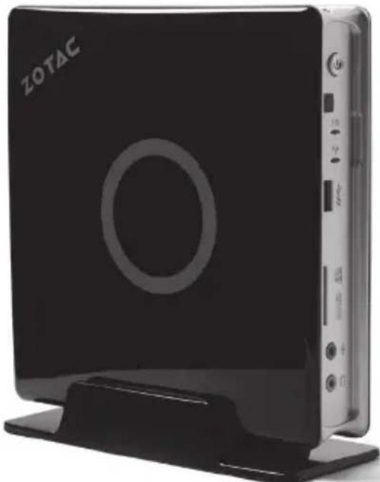
natural_image
Exterior view of a ZOTAC device with front panel and control buttons (no readable text beyond branding)No part of this manual, including the products and software described in it, may be reproduced, transmitted, transcribed, stored in a retrieval system, or translated into any language in any form or by any means, except documentation kept by the purchaser for backup purposes, without the express written permission of ZOTAC.
Products and corporate names mentioned in this manual may not be registered trademarks or copyrights of their respective companies, and are used for identification purposes only. All trademarks are the property of their respective owners.
Every effort has been made to ensure that the contents of this manual are correct and up to date. However, the manufacturer makes no guarantee regarding the accuracy of its contents, and reserves the right to make changes without prior notice.
CAUTION:
Risk of explosion if the battery is replaced with an incorrect type. Batteries should be recycled where possible. Disposal of used batteries must be in accordance with local environmental regulations.
Table of Contents
Product Specifications 3
Safety information 4
Setting up your system 4
Care during use 4
Welcome 5
Package contents 5
Getting to know your ZOTAC ZBOX 6
Front view 6
Rear view----7
BIOS settings of specific functions 8
How to disable the ring LED indicator 8
How to enable USB2.0 charge (for S3/S4/S5 status)----9
How to disable CIR controller (for internal IR receiver)----10
Installing Hardware inside ZOTAC ZBOX 12
Installing a memory module 12
Removing the memory module 13
Installing a hard disk 14
Setting up your ZOTAC ZBOX 16
Positioning your ZOTAC ZBOX---- 18
Installing the stand---- 18
Installing your ZOTAC ZBOX to a monitor----18
IR receiver 19
Remote control 20
Function keys 20
Lithium cell installation---- 21
Installing drivers and software 22
Installing an operating system 22
Installing system drivers----22
Using your ZOTAC ZBOX 23
Configuring wireless connection 23
Configuring wired connection 23
Using a static IP 23
Using a dynamic IP (PPPoE connection)---- 24
Configuring audio output via an HDMI device 24
Product Specifications
Chipset
Intel® H61 Chipset
ProductSize
◆ 188mm x 188mm x 51mm
Microprocessor support
Intel® Core™ T series processors
☐ Operating systems:
◆ Supports Windows 7 32bit/64bit and Windows 8 32bit/64bit
□ System Memory support
◆ Two 204-pin SO-DIMMs DDRIII 1600/1333/1066
◆ Up to 16 GB of memory
USB Ports
- Two USB 3.0 ports (one front panel port, and one top panel port)
◆ Two USB 2.0 ports on the rear panel
Onboard Serial ATA
◆ SATA 3.0 Gb/s transfer rates
✿ Supports one 2.5-inch SATA HDD or SSD (support the device with max 9.5mm height)
Onboard Dual LAN
◆ Supports 10/100/1000 Mbps operation
◆ Supports IEEE 802.3
□ WiFi/Bluetooth support
◆ Compliant with IEEE802.11n Draft 2.0 standard
◆ High speed wireless connection and enhanced wireless security
◆ Fully qualified Bluetooth v4.0
Onboard Audio
◆ Optical SPDIF Output
◆Stereo analog audio output and Microphone input
Green Function
◆Supports ACPI (Advanced Configuration and Power Interface)
☐ Onboard Graphics support
❖ Integrated Intel® HD Graphics 2500/4000 (depends on CPU)
◆ HDMI & DVI output (VGA compatible with adapter)
Safety information
Your ZOTAC ZBOX is designed and tested to meet the latest standards of safety for information technology equipment. However, to ensure your safety, it is important that you read the following safety instructions.
Setting up your system
Read and follow all instructions in the documentation before you operate your system.
Do not use this product near water or a heat source such as a radiator.
- Set up the system on a stable surface with the provided stand. Never use the system alone without the stand.
Openings on the chassis are for ventilation. Do not block or cover these openings. Make sure you leave plenty of space around the system for ventilation. Never insert objects of any kind into the ventilation openings.
Use this product in environments with ambient temperatures between 0°C and 35°C.
If you use an extension cord, please use the UL listed cord and make sure that the total ampere rating of the devices plugged into the extension cord does not exceed its ampere rating.
Care during use
Do not walk on the power cord or allow anything to rest on it.
Do not spill water or any other liquids on your system.
When the system is turned off, a small amount of electrical current still flows. Always unplug all power, modem, and network cables from the power outlets before cleaning the system.
If you encounter the following technical problems with the product, unplug the power cord and contact a qualified service technician or your retailer.
The power cord or plug is damaged.
Liquid has been spilled into the system.
The system does not function properly even if you follow the operating instructions.
The system was dropped or the cabinet is damaged.
The system performance changes.
Welcome
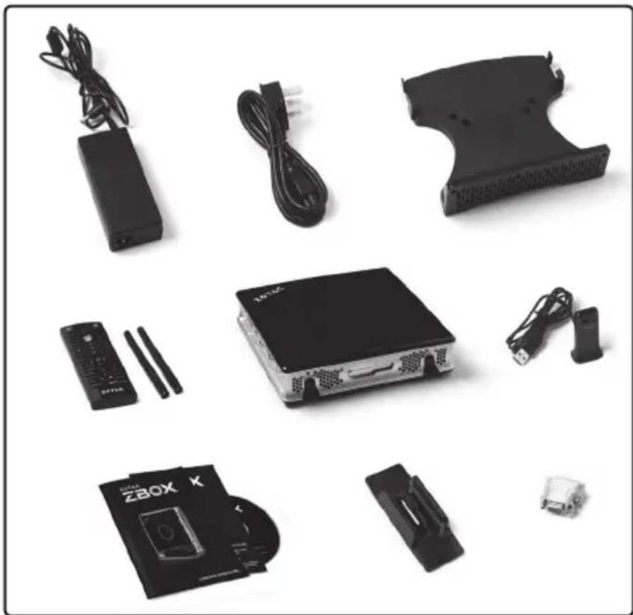
Congratulations on your purchase of the ZOTAC ZBOX. The following illustration displays the package contents of your new ZOTAC ZBOX. If any of the below items is damaged or missed, contact your retailer.
Package contents
• 1 x ZOTAC ZBOX
- 1 x Stand
- 1 x VESA mount
- 1 x AC Adapter
• 1 x DVI-to-VGA Adapter
- 1 x Power Cord
- 2 x Antennas
- 1 x Support DVD
• 1 x Quick Start Guide
• 1 x Remote Control with 2 x CR2032 batteries
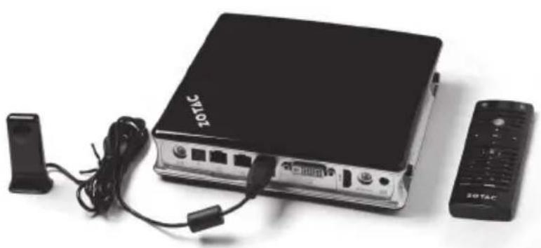
• 1 x USB Extended IR Receiver for Remote Control
• 1 x User Manual & Warranty Card
natural_image
Collection of electronic devices including a ZBOX, USB cable, and power adapter with connectors (no visible text or symbols)Getting to know your ZOTAC ZBOX
Front view
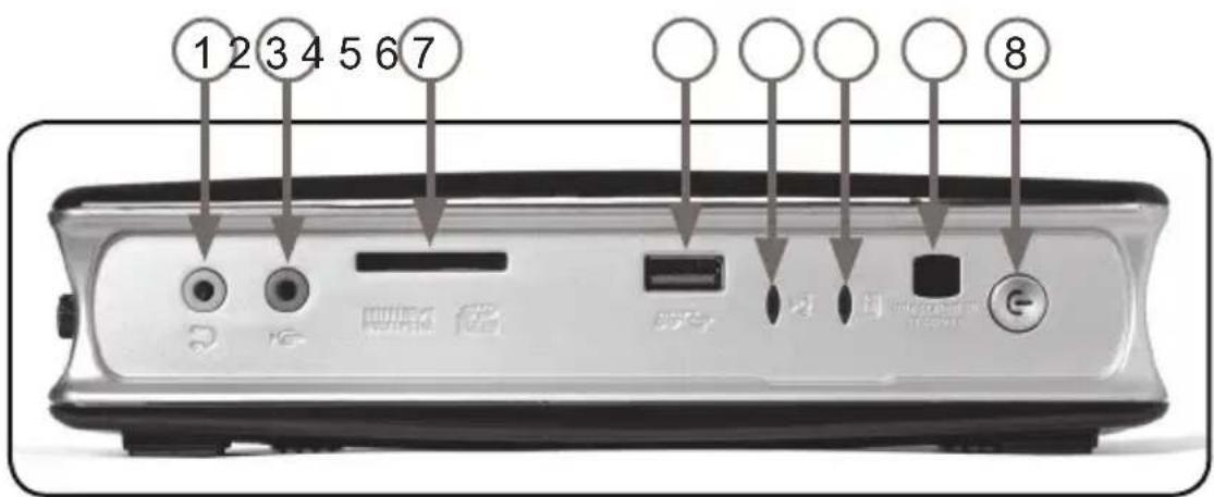
Refer to the diagram below to identify the components on this side of the system
1. Headphone/Audio Out jack
The stereo headphone jack (3.5mm) is used to connect the system's audio out signal to amplified speakers or headphones.
2. Microphone jack
The microphone jack is designed to connect the microphone used for video conferencing, voice narrations or simple audio recordings.
3. Memory card slot
The built-in memory card reader reads SD/SDHC/SDXC/MMC cards used in devices like digital cameras, MP3 players, mobile phones and PDAs.
4. USB 3.0 port
The USB 3.0 port supports the SuperSpeed USB 3.0 devices and is backwards compatible with USB 2.0/1.1 devices. Use this port for USB 3.0 devices for maximum performance with USB 3.0 compatible devices.
5. WiFi LED
The WiFi LED blinks when data is being transferred over WiFi.
6. Hard disk LED
The hard disk LED blinks when data is being written into or read from the hard disk drive.
7. IR receiver
The integrated IR receiver is used to receive signals from the IR remote control.
8. Power switch
The power switch allows powering ON and OFF the system.
Rear view
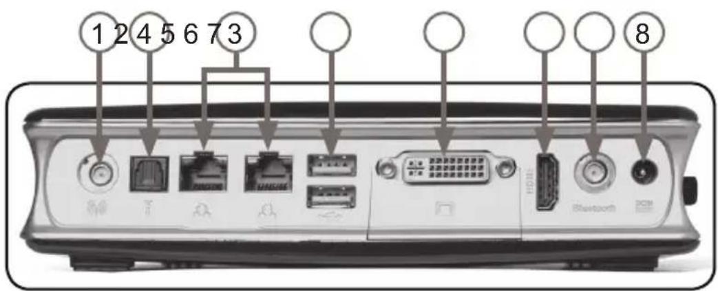
Refer to the diagram below to identify the components on this side of the system.
1. WiFi antenna connector
The WiFi antenna connector supports WiFi antenna module.
2. Optical (SPDIF OUT) jack
Plug an optical cable into this jack for digital audio transfer.
3. LAN ports
The eight-pin RJ-45 LAN ports support standard Ethernet cables for connection to a local network.
4. USB 2.0 ports
The USB (Universal Serial Bus) port is compatible with USB devices such as keyboards, mice, cameras and hard disk drives. They also support USB IR receiver (please refer to page 20).
5. DVI port
The DVI port supports connection to analog monitors and displays.
6. HDMI port
The HDMI (High Definition Multimedia Interface) port supports a Full-HD device such as an LCD TV or monitor to allow viewing on a larger external display.
7. Bluetooth antenna connector
The bluetooth antenna connector supports bluetooth antenna module.
8. Power input (DC19V)
The supplied power adapter converts AC power to DC power for use with this jack. Power supplied through this jack supplies power to the PC. To prevent damage to the PC, always use the supplied power adapter.

The power adapter may become warm to hot when in use. Do not cover the adapter and keep it away from your body.
BIOS settings of specific functions
ZOTAC ZBOX has some specific functions which can be enabled or disabled in BIOS settings, such as LED indicator, USB2.0 charge and CIR controller.
How to disable the ring LED indicator
- Turn on the ZBOX mini-PC, then press
to enter the BIOS SETUP UTILITY. - Use the arrow keys to navigate to the PowerManage menu and select Backlight Control.
![Enable ACPI Auto Configuration [Disabled] Enable Hibernation [Enabled] ACPI Sleep State [S3 (Suspend to RAM)] Lock Legacy Resources [Disabled] S3 Video Repost [Disabled] Restore From AC Power Loss [Power Off] Backlight Control [Enabled] Top USB2.0 S3/S4/S5 Charge [Disabled] Bottom USB2.0 S3/S4/S5 Charge [Disabled] DeepSleep(ERP Compliant) S5 [Disabled] Functions below available when Drop Sleep Disabled. Wake On Lan [Disabled] USB KB/MS Wake Up S1/S3/S4 [Enabled] RTC Wakeup Setting [Disabled] Disable or Enable Backlight +: Select Screen T↓/Click: Select Item Enter/Dbl Click: Select +/-: Charge Opt. F1: General Help F2: Previous Values F9: Optimized Defaults F10: Save & Exit ESC/Right Click: Exit](/content/2026/06/1259664/images/d307c54b0d243a68a4812a1613bcb7e18d6b5d680016e40a2237f80fe70b2f09.jpg)
3. Press and select Disabled.
![Main X-Setting Advanced PcHealth PowerManage Boot Security Save & Exit ZOTAC Enable ACPI Auto Configuration [Disabled] Enable Hibernation [Enabled] ACPI Sleep State [S3 (Suspend to RAM)] Lock Legacy Resources [Disabled] S3 Video Repost [Disabled] Restore From AC Power Loss [Power Off] Backlight Control [Enabled] Top USB2.0 S3/S4/S5 Charge [Disabled] Bottom USB2.0 S3/S4/S5 Charge Backlight Control DeepSleep(EnP Compliant) S5 Enabled Disabled Functions below available when Deep Wake On Lan [Disabled] USB KB/MS Wake Up S1/S3/S4 [Enabled] RTC Wakeup Setting [Disabled] Disable or Enable Backlight +: Select Screen T↓/Click: Select Item Enter/Db1 Click: Select +/-: Change Opt. F1: General Help F2: Previous Values F9: Optimized Defaults F10: Save & EKL ESC/Right Click: Exit](/content/2026/06/1259664/images/b6c53b9ac1bc694a2bf164e3de45a3698133c0055e0df4e725c760850c0713cf.jpg)
4. Press F10 to save the configuration and exit.
How to enable USB2.0 charge (for \3/\4/\$5 status)
- In PowerManage menu, use the arrow key to enter the item Top / Bottom USB2.0 S3/S4/S5 Charge, and select Enabled.
![Main X-Setting Advanced PcHealth PowerManage Boot Security Save & Exit ZOTAC Enable ACPI Auto Configuration [Disabled] Enable Hibernation [Enabled] ACPI Sleep State [S3 (Suspend to RAM)] Lock Legacy Resources [Disabled] S9 Video Repost [Disabled] Restore From AC Power Loss [Power Off] Backlight Control [Disabled] Top USB2.0 S3/S4/S5 Charge [Disabled] Bottom USB2.0 S3/S4/S5 Charge Top USB2.0 S3/S4/S5 Charge DeepSleep(ErP Compliant) S5 Disabled Enabled Functions below available when Wake On Lon [Disabled] USB KB/HS Wake Up S1/S3/S4 [Enabled] RTC Wakeup Setting [Disabled] Top USB2.0 S3/S4/S5 Charge Select Screen Click: Select Item Enter/Ob1 Click: Select +/-: Change Opt. F1: General Help F2: Previous Values F3: Optimized Defaults F10: Save & Exit ESC/Right Click: Exit](/content/2026/06/1259664/images/7e036d07392ebf5f5eb03c427eb783f51c0d76685307c5b0383be53ad749904f.jpg)
2. Press F10 to save the configuration and exit.
Note: Before charging via USB2.0 in S5 status, please make sure the Deep S5 (Deep S5 in PowerManage menu) is disabled.
![Main X-Setting Advanced PcHealth PowerManage Boot Security Save & Exit ZOTAC Enable ACPI Auto Configuration [Disabled] Enable Hibernation [Enabled] ACPI Sleep State [S3 (Suspend to RAM)] Lock Legacy Resources [Disabled] S3 Video Repost [Disabled] Restore From AC Power Loss [Power Off] Backlight Control [Disabled] Top USB2.0 S3/S4/S5 Charge [Enabled] Bottom USB2.0 S3/S4/S5 Charge [Disabled] DeepSleep(ErP Compliant) 95 [Disabled] Functions below available when Deep Sleep Disabled. Wake On Lon [Disabled] USB KB/MS Wake Up S1/S3/S4 [Enabled] RTC Wakeup Setting [Disabled] Deep S5 Supports or not +: Select Screen T#/Click: Select Item Enter/DBI Click: Select +/-: Change Opt. F1: General Help F2: Previous Values F3: Optimized Defaults F10: Save & Exit ESC/Right Click: Exit](/content/2026/06/1259664/images/9e24298b4b383e2427daf2640321d25df207d87acd0365bfa294021bc924b356.jpg)
How to disable CIR controller (for internal IR receiver)
- Use the arrow keys to navigate to Advanced > OnBoard Device Control > CIR Controller Configuration.
![Advanced ZOTAC OnBoard Device Control Serial Port 0 Configuration CIR Controller Configuration PCI-E GigaLAN Controller1 [Enabled] PCI-E GigaLAN Controller2 [Enabled] USBS.0 Ports Controller [Enabled] SATA Mode Selection [AHCII] PCB Azalia Configuration Azalia [Auto] Azalia Internal HDMI Codec [Enabled] Azalia HDMI codec Port B [Enabled] Azalia HDMI codec Port C [Enabled] Azalia HDMI codec Port D [Enabled] Set Parameters of CIR Controller (CIR) +: Select Screen T↓/Click: Select Item Enter/DbI Click: Select +/-: Change Opt. F1: General Help F2: Previous Values F5: Optimized Defaults F10: Save & Exit ESC/Right Click: Exit OFF status utility - Copy icon - 801 and icon move rights, Inc.](/content/2026/06/1259664/images/4bbd14587e1f68fd0abe9e7b93353bfb61d08683141b4dd473170cadb919fee8.jpg)
2. Enter CIR Controller and select Disabled.
![Advanced ZOTAC® CIR Controller Configuration CIR Controller Device Settings [Enabled] Reset Required Change Settings [Auto] Make Up by CIR Device [Enabled] CIR Controller Disabled Enabled Enable or Disable CIR Controller +: Select Screen ↑/Click: Select Item Enter/Obi Click: Select +/-: Change Opt. F1: General Help F2: Previous Values F3: Optimized Defaults F10: Save & Exit ECC/Right Click: Exit USE: Save Utility - Copy Level To Build Explanter Monotronics, Inc.](/content/2026/06/1259664/images/38ac3e3068706ff1f8c3040a2cf657dbe019b86568ce8c598984a59be0cb7db9.jpg)
Enabled: enable the internal IR receiver (default) Disabled: disable the internal IR receiver
- Press F10 to save the configuration and exit.
Installing Hardware inside ZOTAC ZBOX
Before installing hardware, please follow the instructions below to remove the cover of your ZOTAC ZBOX.
- Unscrew.
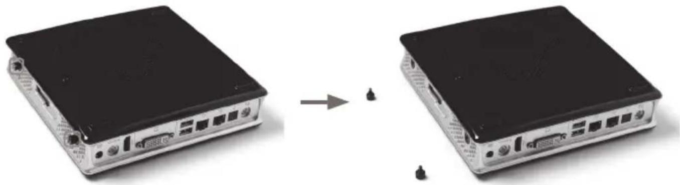
natural_image
Two black network switches with ports and connectors, shown from front and side views (no text or symbols visible)- Gently remove the cover as the image below.
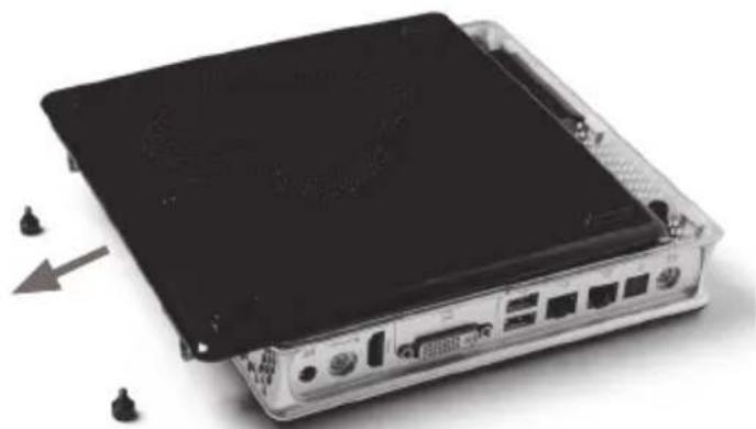
natural_image
Exterior view of a black electronic device with ports and connectors, showing a close-up of its front panel (no text or symbols visible)Installing a memory module
- Locate the SO-DIMM memory slots and insert a SO-DIMM memory module into the slot at a 45 degree angle.
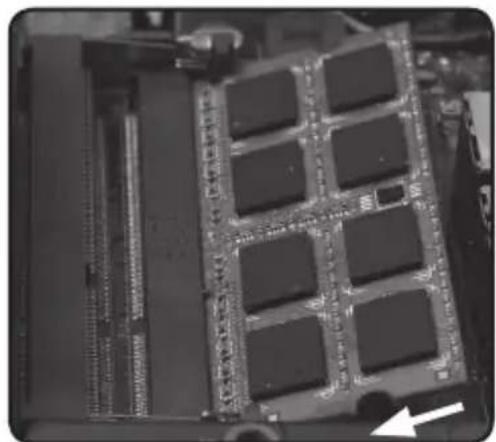
natural_image
Close-up of a computer RAM module with visible slots and circuitry (no text or symbols)Note: When installing two SO-DIMM memory modules, please insert a module into the lower slot first.
- Gently press down on the memory module until it locks into place by the arms of the memory slot.
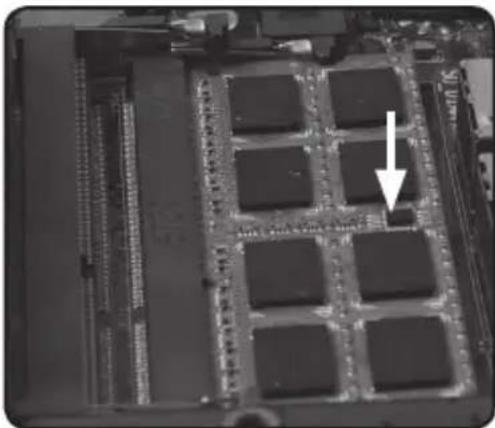
natural_image
Close-up of a microchip or integrated circuit board with multiple chip modules and a white arrow pointing to a specific component (no visible text or symbols)Note: This ZOTAC ZBOX accommodates two DDR3 SO-DIMM memory modules. You must install at least one module in one of the two slots.
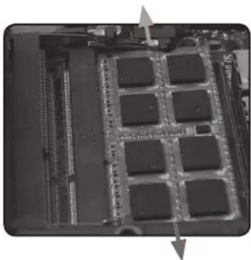
Removing the memory module
- Locate the SO-DIMM memory slot and gently press the two arms securing the memory module outwards, as shown in the image below, to release the memory module.
natural_image
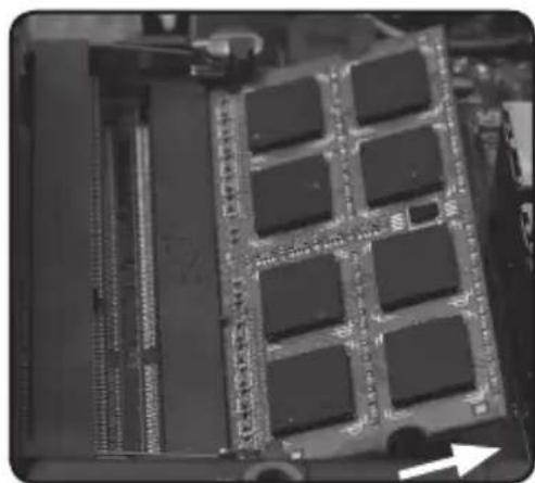
Close-up of an electronic circuit board with multiple integrated circuits and a central chip (no visible text or symbols)- Remove the memory module from the slot at a 45-degree angle.
natural_image
Close-up of a computer RAM module with visible slots and circuitry (no text or symbols)Installing a hard disk
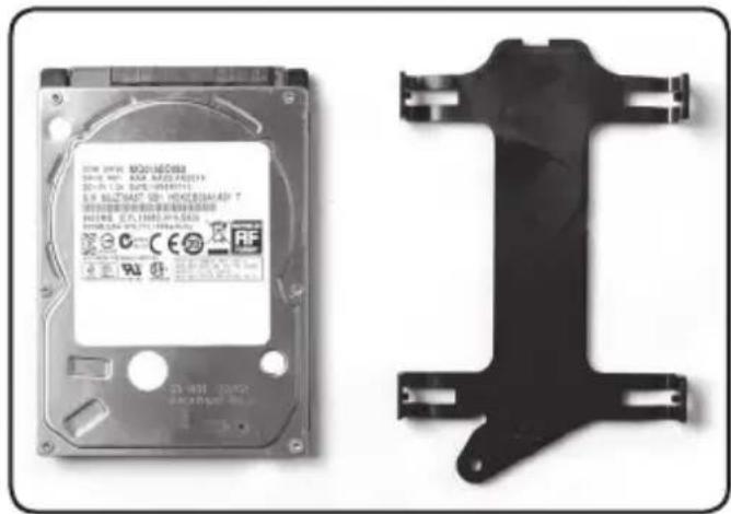
- Locate the 2.5-inch SATA hard disk and the hard disk bracket.
natural_image
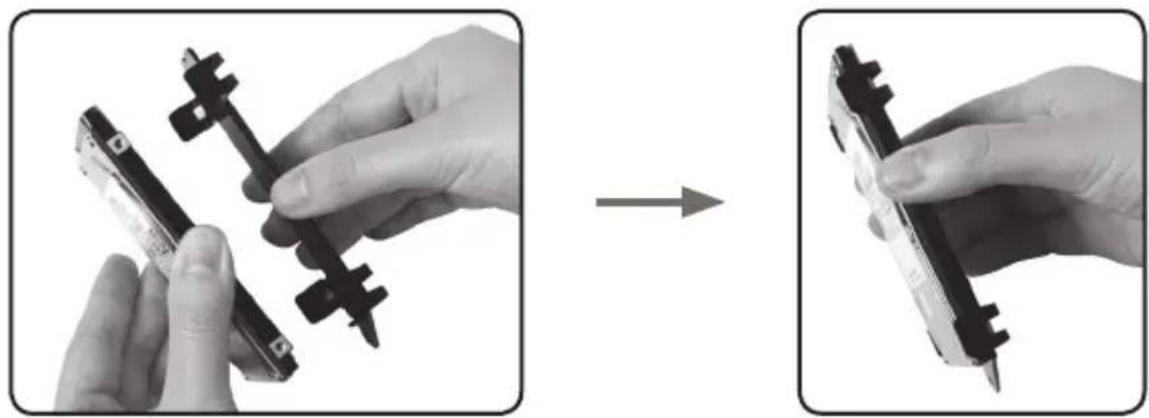
Two hard disk components: one with a white label and certification marks, the other with a black plastic bracket (no visible text or symbols on the device body)- Install the hard disk to the hard disk bracket.
natural_image
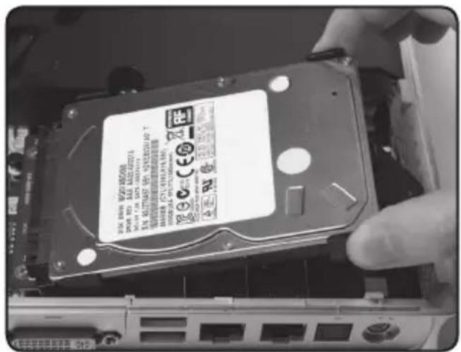
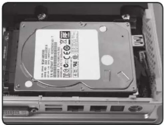
Two-step illustration showing hands holding a device with black connectors, before and after assembly (no text or symbols)- Insert the hard disk into the slot at a 45 degree angle and gently slide into the connector.
- Reinstall the thumb screw.
Setting up your ZOTAC ZBOX
You need to connect peripherals before using your ZOTAC ZBOX.
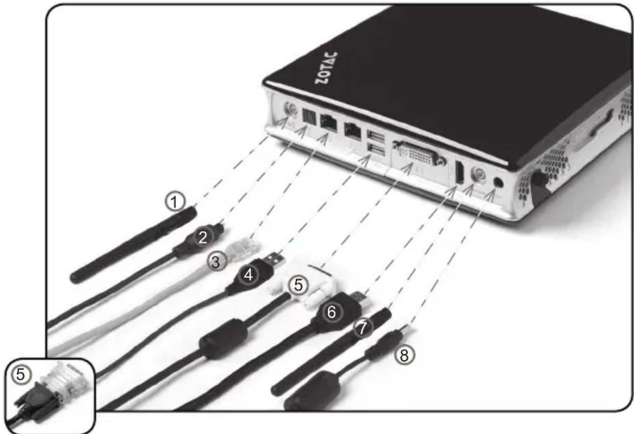
1. Connecting a WiFi antenna module
Connect a WiFi antenna module to the WiFi antenna connector.
2. Connecting an optical S/PDIF output
Connect a digital audio device via optical S/PDIF output.
3. Connecting to a network device
Connect one end of a network cable to the LAN port on the system rear panel and the other End to a hub or switch.
4. Connecting to USB 2.0 devices
Connect USB devices like wired/wireless keyboards (varying with areas), mouse devices and printers to the USB ports on the system rear panel.
5. Connecting to a DVI or VGA display
Connect one end of a DVI/VGA cable to an HDTV or monitor, and the other end to the DVI port on the system rear panel. If using a VGA connection, please use included DVI-to-VGA adapter.
6. Connecting to an HDMI display
Connect one end of an HDMI cable to the HDMI port on the system rear panel and the other end to a HDMI-compatible display such as an HDTV or monitor.
7. Connecting a Bluetooth antenna module
Connect a bluetooth antenna module to the bluetooth antenna connector.
8. Turning on the system
Connect the supplied AC adapter to the DC IN jack on the system rear panel and then press the power switch on the front panel to turn on the system.

When your ZOTAC ZBOX is not in use, unplug the power adapter or switch off the AC outlet to save on power consumption.
Positioning your ZOTAC ZBOX
Do not position the ZOTAC ZBOX where the ventilation holes are covered. To guarantee proper use, leave 4 inches (10 cm) spacing in front of the ventilation holes.
ZOTAC mini-PC system provide ample connectivities in tiny space, please choose connectors and cables in appropriate size to avoid interference.
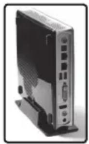
Installing the stand
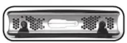
Erect your ZOTAC ZBOX with the supplied stand. To do so :
- Locate the screw hole on the bottom of the ZOTAC ZBOX.
- Align the stand screw to the PC screw hole and then secure the Stand to the PC with a coin.
Do not place your ZOTAC ZBOX on the desktop without the stand.
natural_image
Diagram of a device with two human silhouettes and a central rectangular component (no text or symbols)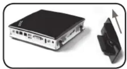
natural_image
Exterior view of a device with a black top and a black plastic cover, showing an upward arrow (no text or symbols)
natural_image
Front view of a black server tower with ports and connectors (no visible text or labels)Installing your ZOTAC ZBOX to a monitor
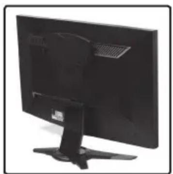
You can also install your ZOTAC ZBOX to the back of a monitor. To do so:
- Secure the VESA mount to your monitor with four screws (HNM/M4x8).
- Place your ZOTAC ZBOX on the VESA mount noting the correct alignment and then secure the PC to the VESA mount with a coin.
To fasten the VESA mount, your monitor must comply with VESA75 Or VESA100 standard.
Mechanical Loading Stability - Mounting of the equipment on the backside of the monitor should be lay this equipment on a reliable surface when install. A drop or fall could cause injury.
If the total weight of your monitor and ZOTAC ZBOX is over 7kg, the system may be unstable.
natural_image
Back view of a black computer monitor with a stand and ventilation grille (no visible text or symbols)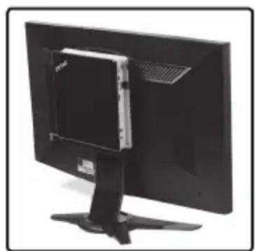
natural_image
Back view of a black computer monitor with a small display case on top (no visible text or symbols)IR receiver
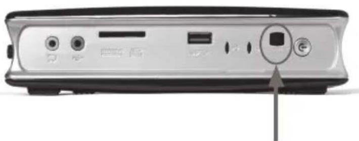
Users can control compatible applications with the integrated IR receiver or included external USB IR receiver.
- Integrated IR receiver
Note: Please install CIR driver from DVD before using the integrated IR receiver.
natural_image
Back panel of a computer monitor with ports and buttons, showing a square button on the right side (no text or symbols visible)Integrated IR receiver
- External USB IR receiver (please connect the external USB IR receiver to a USB 2.0 port)
natural_image
Black wireless router with attached remote control unit and cable, no visible text or symbols on device body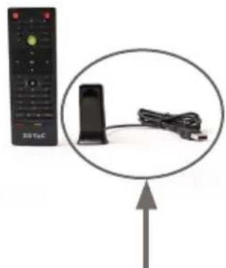
natural_image
Retro television remote control with attached cable and antenna, no visible text or symbolsExternal USB IR receiver
Remote control
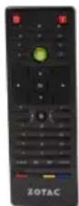
ZOTAC ZBOX is shipped with a remote control. Follow the instructions below to use the remote control.
Function keys
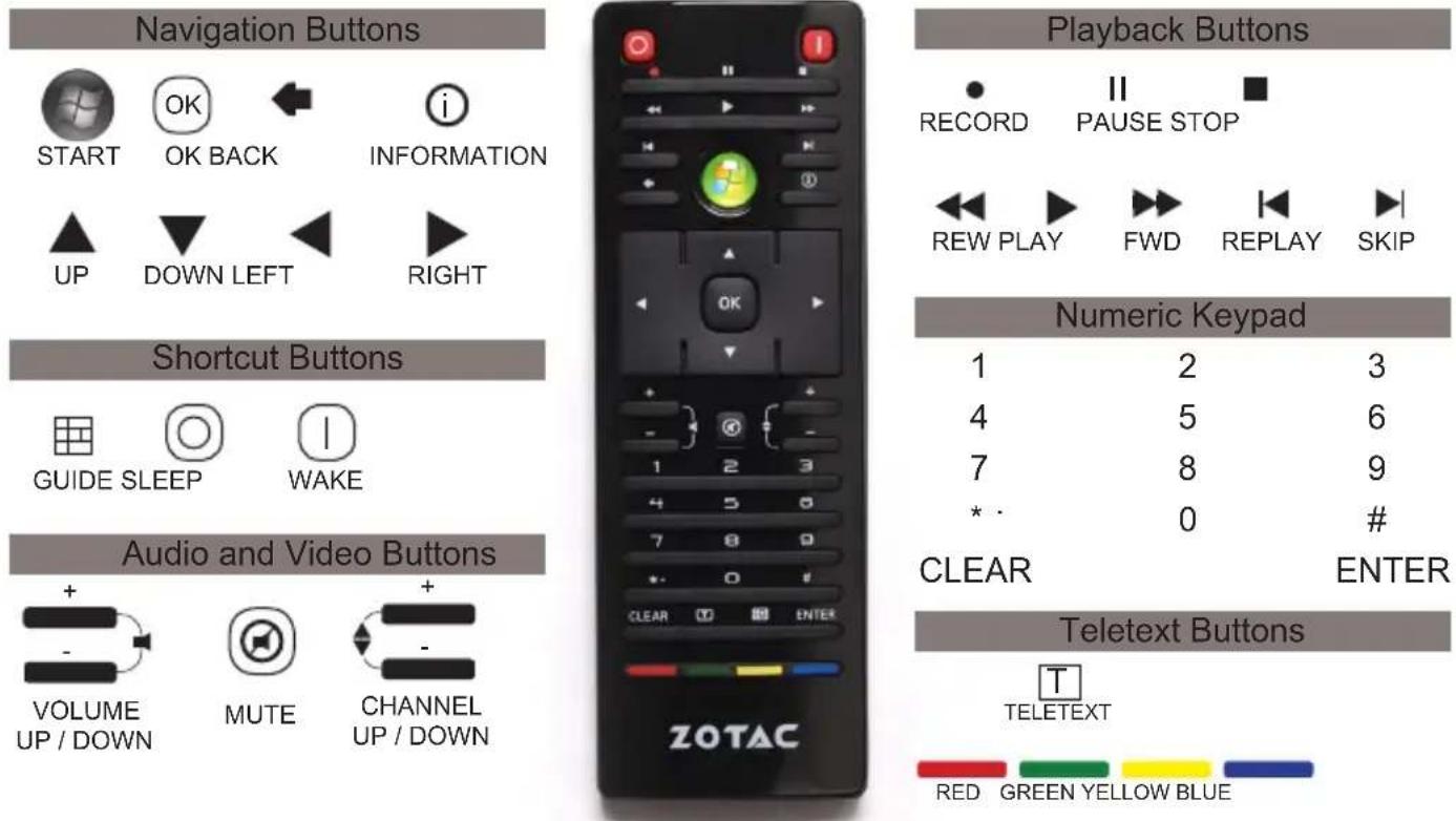
Note: Some remote control functions listed above are only available with the relative hardware equipments. If the hardware equipments you adopt are not compatible with the system, you are unable to use these functions. This product is designed to meet MCE standards. The MCE remote control is compliant with Windows 7.
Lithium cell installation
- Locate the arrow on the rear cover of the remote control, and push the cover as the arrow direction.
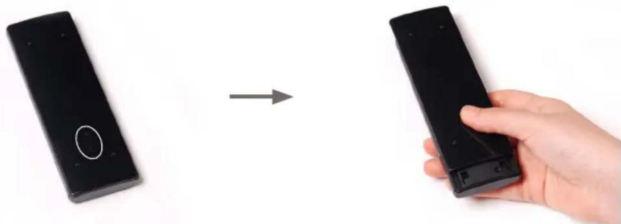
natural_image
Hand holding a black remote control with an arrow indicating transformation (no text or symbols visible)- Remove the rear cover, and insert the CR2032 lithium cells into the battery jar at a 45 degree angle.
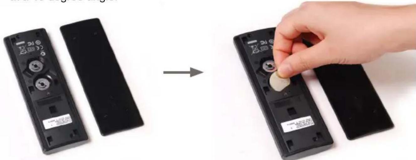
natural_image
Hand placing a small object into a black remote control case, showing device states before and after assembly (no text or symbols visible)- Gently press down on the CR2032 lithium cells, and reinstall the rear cover.
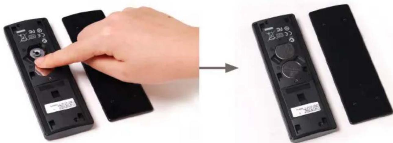
natural_image
Hand placing a remote control panel with a rotary knob, before and after assembly (no text or symbols visible)Installing drivers and software
Installing an operating system
The ZOTAC ZBOX does not ship with an operating system preinstalled. The user must install the operating system before the ZOTAC ZBOX can be used. The following operating systems are supported:
- Windows 7
- Windows 8
Follow the instructions below to install an operating system:
- Attach external DVD drive via USB 2.0
- Insert disk for operating system (Windows or Linux).
- Wait for the ZOTAC ZBOX to boot from the disk.
- Follow the onscreen directions to install the operating system.
- Install system drivers to gain full functionality of the ZOTAC ZBOX hardware and features.
Note: For best compatibility, please only use the USB 2.0 ports as the OS installation source drive connection.
Installing system drivers
Before you can use the full features of the ZOTAC ZBOX, the system drivers must be installed. The following types of operating systems are supported by the ZOTAC ZBOX driver DVD:
- Windows 7
- Windows 8
Follow the instructions below to install the system drivers:
-
Insert the ZOTAC ZBOX driver DVD. If autorun is enabled, the driver installation main menu will show up automatically. If autorun is disabled, you may click the file Launch.EXE to bring up the driver installation main menu.
-
The following drivers are available on the DVD:
-
Intel Chipset Driver
• HDA Sound Driver - Intel Graphics Driver
- Ethernet PCI-E Driver
- Wireless Network Driver
• Intel Management Engine - Bluetooth Driver
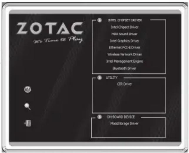
- CIR Driver
- MassStorage Driver
• USB Charger (optional)
Note: If you want to use USB charger for iPhone/iPad, please install the driver at X:\Utility\Software\Usb Charger\setup.exe (X: your driver disk letter).
Each driver must be installed individually to ensure proper operation of the ZOTAC ZBOX.
- Select the driver you want to install. The driver installer should launch.
- Follow the onscreen instructions to install the drivers.
- Restart the system.
Using your ZOTAC ZBOX
Configuring wireless connection
To connect to a wireless network, follow the instructions below:
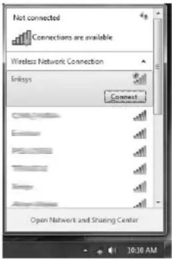
- Double-click the crossed wireless network icon (pic) on the notification area.
- Select the wireless network you want to connect to from the list and click Connect.
- After connection was established, you will see Connected.
For security concerns, Do NOT connect to an unsecured network, otherwise, the transmitted information without encryption might be visible to others.
Enter the network security key if necessary.
Configuring wired connection Using a static IP
- Right-click the network icon on the notification area and select Open Network Connections.
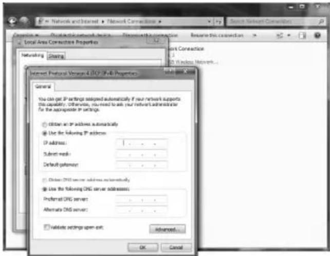
- Right-click Local Area Connection and select Properties.
- Highlight Internet protocol (TCP/IP) and click Properties.
- Select Use the following IP address.
-
Enter your IP address, subnet mask and Default gateway.
-
If needed, enter the preferred DNS server address.
-
After entering all of the related values, click OK to finish the configuration.
Using a dynamic IP (PPPoE connection)
- Repeat Step 1-3 in the previous section.
- Select Obtain an IP address automatically and click OK.
- Click Create a new connection to start the NEW Connection Wizard.
- Click Next.
-
Select Connect to the Internet and click Next.
-
Select Set up my connection manually.
-
Select your connection type and click Next.
-
Enter your ISP Name and click Next.
-
Enter your User name and Password. Click Next.
-
Click Finish to finish the configuration.
-
Enter your user name and password. Click Connect to connect to the
![Control Panel Home Manage wireless networks Change adapter settings Change advanced sharing settings View your basic network information and set up connections [One computer] Connect or Document View your active networks Access type: Internet HomeGroups Internet Internet Home network Change your networking settings Set up a new connection to a network Set up a new network, broadband, dial-up, or access point. Connect for a network Connect or connect to a wireless, wall Choose homegroup and sharing options Access file and problem located on other Two electronic problems Diagnose and repair network problems Select up a connection or network Choose a connection option Connect to the Internet Set up a new network, broadband, dial-up, or access points Connect to a new network or create a new wireless profile. Connect to a workplace Set up a dial-up on WiFi connectivity by your workplace. Connect to the Internet using a dial-up connection. Next Cancel](/content/2026/06/1259664/images/7520a413a9591008be699df4e11766d2d3c402217e09931de697fa27ff70cfa4.jpg)
Contact your internet Service Provider (ISP) if you have problems connecting to the network.
Configuring audio output via an HDMI device
Follow the steps below to enable audio output via HDMI when connecting the ZOTAC ZBOX to a TV or receiver via HDMI.
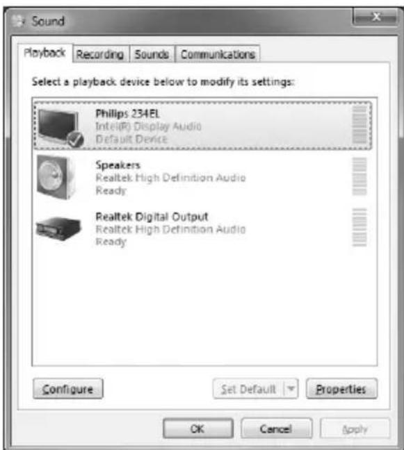
- Access the Sound settings via the system Control Panel.
- Under Playback devices, click the display device item "Philips 234EL" (the device name depends on your display brand and model).
- Click the "Set Default" in the lower right hand corner.
- Click "OK" to exit the setup.
ZOTAC®
It's Time to Play
WWW.ZOTAC.COM

CE
FC
10


- ZOTAC ZBOX User's Manual
- CAUTION:
- Table of Contents
- Product Specifications 3
- Safety information 4
- Welcome 5
- Getting to know your ZOTAC ZBOX 6
- BIOS settings of specific functions 8
- Installing Hardware inside ZOTAC ZBOX 12
- Setting up your ZOTAC ZBOX 16
- Positioning your ZOTAC ZBOX---- 18
- Installing drivers and software 22
- Using your ZOTAC ZBOX 23
- Product Specifications
- Chipset
- ProductSize
- Microprocessor support
- ☐ Operating systems:
- □ System Memory support
- USB Ports
- Onboard Serial ATA
- Onboard Dual LAN
- □ WiFi/Bluetooth support
- Onboard Audio
- Green Function
- ☐ Onboard Graphics support
- Safety information
- Setting up your system
- Care during use
- Welcome
- Package contents
- Getting to know your ZOTAC ZBOX
- Front view
- Headphone/Audio Out jack
- Microphone jack
- Memory card slot
- USB 3.0 port
- WiFi LED
- Hard disk LED
- IR receiver
- Power switch
- Rear view
- WiFi antenna connector
- Optical (SPDIF OUT) jack
- LAN ports
- USB 2.0 ports
- DVI port
- HDMI port
- Bluetooth antenna connector
- Power input (DC19V)
- BIOS settings of specific functions
- How to disable the ring LED indicator
- Press and select Disabled.
- Press F10 to save the configuration and exit.
- How to enable USB2.0 charge (for \3/\4/\$5 status)
- Press F10 to save the configuration and exit.
- How to disable CIR controller (for internal IR receiver)
- Enter CIR Controller and select Disabled.
- Installing Hardware inside ZOTAC ZBOX
- Installing a memory module
- Removing the memory module
- Installing a hard disk
- Setting up your ZOTAC ZBOX
- Connecting a WiFi antenna module
- Connecting an optical S/PDIF output
- Connecting to a network device
- Connecting to USB 2.0 devices
- Connecting to a DVI or VGA display
- Connecting to an HDMI display
- Connecting a Bluetooth antenna module
- Turning on the system
- Positioning your ZOTAC ZBOX
- Installing the stand
- Installing your ZOTAC ZBOX to a monitor
- IR receiver
- Remote control
- Lithium cell installation
- Installing drivers and software
- Installing an operating system
- Installing system drivers
- Using your ZOTAC ZBOX
- Configuring wireless connection
- Configuring wired connection Using a static IP
- Using a dynamic IP (PPPoE connection)
- Configuring audio output via an HDMI device
- ZOTAC®
Brand : Zotac
Model : ZBOX ID88 Plus
Category : Desktop computer