
IR10 - Remote control Chief - Free user manual and instructions
Find the device manual for free IR10 Chief in PDF.


| Product Type | Remote control |
| Brand | Chief |
| Model | IR10 |
| Dimensions (W x H x D) | 5.0 x 1.2 x 0.8 inches |
| Weight | 3.5 oz (approx. 100 g) |
| Power Supply | 2 x AAA batteries (not included) |
| Battery Life | Approximately 6 months with normal use |
| Signal Type | Infrared (IR) |
| Range | Up to 30 feet (10 meters) |
| Compatibility | Most Chief AV equipment and universal IR devices |
| Functions | Power, volume, channel, input source, menu navigation, number pad, mute |
| Backlight | No backlight |
| Programming | Manual code entry or auto-search |
| Mounting | Handheld, tabletop |
| Material | Plastic |
| Color | Black |
| Usage | Indoor use only |
| Maintenance | Clean with a soft, dry cloth; avoid liquids |
| Safety Warnings | Keep away from water and heat sources; do not disassemble |
| Spare Parts | Batteries only (standard AAA) |
Frequently Asked Questions - IR10 Chief
User questions about IR10 Chief
0 question about this device. Answer the ones you know or ask your own.
Ask a new question about this device
Download the instructions for your Remote control in PDF format for free! Find your manual IR10 - Chief and take your electronic device back in hand. On this page are published all the documents necessary for the use of your device. IR10 by Chief.
USER MANUAL IR10 Chief
INSTALLATION INSTRUCTIONS

Infrared Remote Control Accessory
DISCLAIMER
Milestone AV Technologies, and its affiliated corporations and subsidiaries (collectively, "Milestone"), intend to make this manual accurate and complete. However, Milestone makes no claim that the information contained herein covers all details, conditions or variations, nor does it provide for every possible contingency in connection with the installation or use of this product. The information contained in this document is subject to change without notice or obligation of any kind. Milestone makes no representation of warranty, expressed or implied, regarding the information contained herein. Milestone assumes no responsibility for accuracy, completeness or sufficiency of the information contained in this document.
Chief® is a registered trademark of Milestone AV Technologies. All rights reserved.

IMPORTANT SAFETY INSTRUCTIONS

WARNING: A WARNING alerts you to the possibility of serious injury or death if you do not follow the instructions.

CAUTION: A CAUTION alerts you to the possibility of damage or destruction of equipment if you do not follow the corresponding instructions.

WARNING: Failure to read, thoroughly understand, and follow all instructions can result in serious personal injury, damage to equipment, or voiding of factory warranty! It is the installer's responsibility to make sure all components are properly assembled and installed using the instructions provided.

WARNING: Use this accessory only for its intended use as described in these instructions.

WARNING: Never operate this accessory if it is damaged. Return the accessory to a service center for examination and repair.

WARNING: Do not use this product outdoors.
--SAVE THESE INSTRUCTIONS--
LEGEND

TOOLS REQUIRED FOR INSTALLATION

PARTS

B (1)
[IR Receiver]

natural_image
Simple line drawing of a coiled cable with a small connector at the top (no text or symbols)A (1)
[IR to Dry Control
Accessory]

natural_image
Isometric line drawing of a cabinet or enclosure with three stacked compartments (no text or symbols)
C (1) [Remote control]
INSTALLATION


WARNING: All wiring should be performed following all local codes and ordinances.
NOTE: This device can provide control of any device set up for momentary dry contact inputs. See Dry Contact Closures section.
Locate and Install IR Receiver
The IR receiver consists of two parts. The IR to dry control accessory (A) and the IR Receiver (B).
To install the IR Receiver:
- Determine a location to place the IR to Dry Control accessory (A) box taking into consideration the desired location of the IR Receiver (B), as well as access to the box to connect control wiring after installation.
- Connect IR Receiver (B) to the IR to Dry Control accessory (A).
- Route IR receiver (B) to desired mounting location and secure.

Figure 1
NOTE: The IR10 can use 12V through 24V power that can be obtained directly from the control boards within some Chief automated products.
Table 1: Chief Product Connections to IR-10
| IR-10 | SL-150 Internal | SL-150 External | SL-236 Internal | SL-236 External | PCL | PUL |
| +12V | 4 (12V DC) | 10 (12V DC) | 4 (12V DC) | 10 (12V DC) | 4 (12V DC) | 4 (12V DC) |
| GND | 3 (ground) | 9 (ground) | 3 (ground) | 9 (ground) | 3 (ground) | 3 (ground) |
| C1 | 12 (retract) | 3 (retract) | 12 (retract) | 3 (retract) | 12 (retract) | 11 (extend) |
| C2 | 11 (extend) | 4 (extend) | 11 (extend) | 4 (extend) | 11 (extend) | 12 (retract) |
| C3 | No Connection | No Connection | 9 (service) | 11 (service) | No Connection | No Connection |
| COMM | 13 (ground) | 9 (ground) | 13 (ground) | 9 (ground) | 13 (ground) | 13 (ground) |
NOTE: If remote does not operate properly see the installation instructions provided with mount, or contact a Chief Customer Service Representative.
- Using a slotted screwdriver, connect power and signal wires to the IR to Dry Control accessory (A). (See Figure 2)

| KEY CONTROL OUTPUT | |
| A COMMON | |
| B PRESET 1 | |
| C DOWN | |
| D | UP |
| E GROUND | |
| F 12V or 24V Power supply | |
Figure 2
The remote control has a range of 20-30 ft (6-9m), and is powered by 2 AAA batteries.
IMPORTANT ! : Power must be provided to device and IR receiver must be installed in order to access extended IR10 programming options.
Normal Operating Mode

| KEY FUNCTION REQUIRED ACTION | |
| 1 NOT USED N/A | |
| 2 NOT USED N/A | |
| 3 CLOSE CONTACT #1 PRESS AND HOLD | |
| 4 NOT USED N/A | |
| 5 NOT USED N/A | |
| 6 NOT USED N/A | |
| 7 CLOSE CONTACT #2 PRESS AND HOLD | |
| 8 NOT USED N/A | |
| 9 NOT USED N/A | |
| 10 CLOSE CONTACT #3 PRESS AND HOLD | |
| 11 NOT USED N/A | |
| 12 NOT USED N/A | |
| 13 NOT USED N/A | |
Figure 3
Changing System Codes
Settings are changed by a combination of remote button presses and partially disassembling the box to change specific jumper settings.
NOTE: For changing what the box expects to receive, you need to remove the housing and remove a jumper (J5).
- Remove four Phillips screws from housing and remove housing cover. (See Figure 4)
- Remove jumper. (See Figure 4)
- Replace housing cover and four screws removed in Step 1.
NOTE: This will switch the IR-10 over to the 82 system code. The remote control will also need to be switched over. (See Table 1-2)
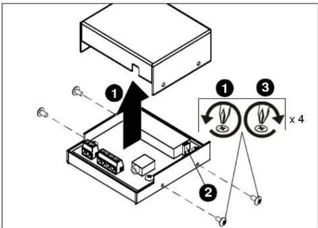
Figure 4
Changing System Code for the Remote
- Press and Release Key 3 + 7 (Enter Setup Mode)
- Press and Release Key 10
- Press and Release Key 11 - LED Blinks Twice
- Select System Code - Table 2
- Press and Release Key 2 - LED Blinks 4 times
(Exit Setup Mode)
Table 2: Remote Control System Code
| System Code Press + Release | |
| 6E (Default) 10, 10 | |
| 82 (IR-10) 10, 11 | |
OPERATIONS
Dry Contact Closures
The IR-10 provides dry contacts based on IR input.
Example: Pressing the 'UP' button on the remote will cause a connection to be made between COM and C1. This connection can be used to trigger other devices (SL, Cinematic, or any third party device that requires this type of input).
NEC Protocol
The modulated carrier is usually derived from 455kHz and is 1/12 of the frequency with 1/3 duty cycle.
When data are transmitted repeatedly, the frame cycle is 107.9ms or 186 period.
A frame consists of a syn pulse, an eight-bit custom code, an eight-bit inverted custom code, an eight-bit data code and an eight-bit inverted data code.
IR-10 Programming
IR-10 Control Features:
• Carrier Frequency: 38KHz
• Protocol: NEC - Full Repeat
- System Code(s): 6E (Default) - Multiple Codes
Selected via Key-Press (See Figure 3)
Table 3: IR Command Code
| Key Number Key Name Hex Code Hex Code (IR-10) | |||
| 3 RETRACT | 07 | 1D | |
| 7 EXTEND | 0D | 41 | |
| 10 | PRESET 1 | 12 | 40 |
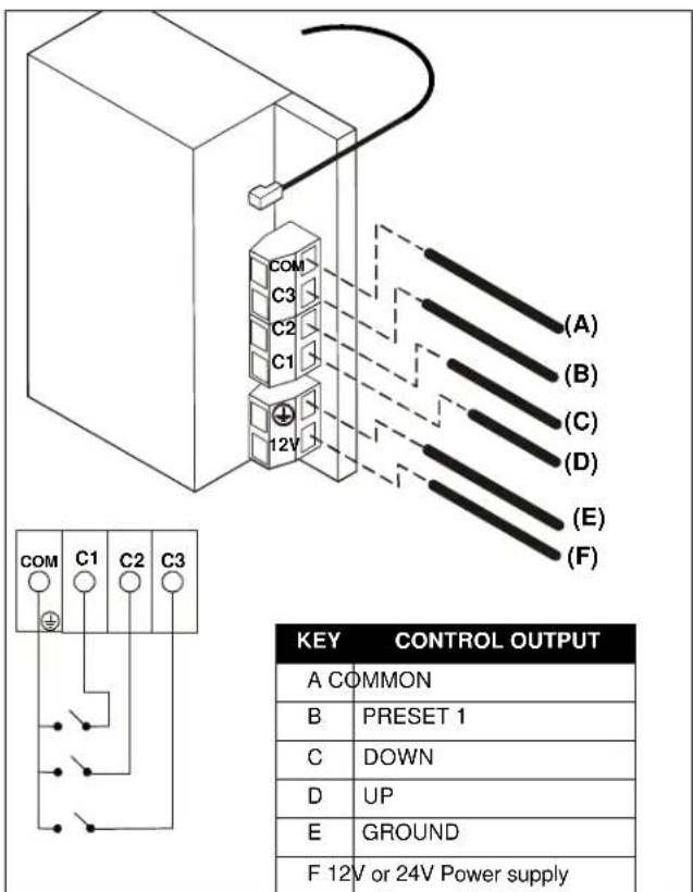
Figure 5

flowchart
graph TD
    A["186T"] --> B["Syn Pulse"]
    B --> C["C0 C1"]
    C --> D["C5 C6 C7 C0 C1"]
    D --> E["C5 C6 C7 D0 D1"]
    E --> F["D5 D6 D7 D0 D1"]
    F --> G["D5 D6 D7"]
    G --> H["End of Transmission"]

    I["Custom code 8 bit"] --> J["Inverted Custom Code 8 bit"]
    J --> K["Data Code 8 bit"]
    K --> L["Inverted Data code 8 bit"]

    M["Syn Pulse"] --> N["15.5T"]
    N --> O["8T"]

    P["Data "0""] --> Q["T T"]

    R["Data "1""] --> S["T 3T"]

    T["End of transmission"] --> U["T"]

    V["Subsequent frames"] --> W["15.5T"]
    W --> X["4T T 6T"]
Figure 6
Installation Instructions
Brand : Chief
Model : IR10
Category : Remote control