
Coronis MFGD-5421 - Monitor Barco - Free user manual and instructions
Find the device manual for free Coronis MFGD-5421 Barco in PDF.


| Product Type | Diagnostic Medical Grade LCD Monitor |
| Brand | Barco |
| Model | Coronis MFGD-5421 |
| Display Size | 21.3 inches (diagonal) |
| Resolution | 2560 x 2048 (5 Megapixels) |
| Pixel Pitch | 0.165 mm |
| Aspect Ratio | 5:4 |
| Luminance | 700 cd/m² (typical) |
| Contrast Ratio | 800:1 (typical) |
| Color/Grayscale | Grayscale (14-bit processing) |
| Inputs | DVI-I, DisplayPort |
| Power Consumption | 100W (typical), 240V, 50/60Hz |
| Dimensions (WxHxD) | 462 x 530 x 222 mm (with stand) |
| Weight | 13 kg (approx) |
| Operating Temperature | 5°C to 40°C |
| Humidity | 20% to 85% non-condensing |
| Regulatory Compliance | IEC 60601-1, FCC Class B, CE |
| Warranty | 5 years (including backlight) |
| Accessories | DVI cable, DisplayPort cable, power cord, user manual |
| Special Features | DICOM calibrated, Built-in front sensor, Ambient light compensation |
Frequently Asked Questions - Coronis MFGD-5421 Barco
User questions about Coronis MFGD-5421 Barco
0 question about this device. Answer the ones you know or ask your own.
Ask a new question about this device
Download the instructions for your Monitor in PDF format for free! Find your manual Coronis MFGD-5421 - Barco and take your electronic device back in hand. On this page are published all the documents necessary for the use of your device. Coronis MFGD-5421 by Barco.
USER MANUAL Coronis MFGD-5421 Barco
natural_image
Close-up of a BRCO Med Computer Award board (no visible text or symbols on the circuit itself)Installation & User Manual
(This page intentionally left blank.)
Copyright notice....7
Preface 8
Safety Instructions.... 12
Recommendations for using your display system.... 15
Display Controller Installation ....17
Which display controller? 19
Installing a Barco display controller 19
Overview.... 19
Installation Procedure 22
Display Installation.... 29
Overview.... 31
Introduction 31
Package contents 32
Controls and connectors.... 33
Installation.... 35
Precautions.... 35
Before installing the display.... 35
Portrait or landscape position.... 36
Connecting the cables.... 37
Routing the signal cables 38
Using the USB hub.... 39
Tilt and swivel positioning.... 40
Starting up 40
How to avoid image retention 41
Software Installation 43
Driver and software installation prerequisites.... 45
Installing the BARCO MXRT drivers and software.... 46
Automated display configuration 48
Reinstalling drivers.... 48
Uninstalling the drivers and software.... 49
Command line (Silent) Install of Drivers and Software...... 50
Installing the BARCOMED CORONIS or Nio drivers and software ..... 52
Automated display configuration.... 54
Reinstalling drivers.... 54
Uninstalling the drivers and software.... 54
Command line (Silent) Install of Drivers and Software...... 55
Display Controller Tools 57
Languages supported.... 59
Barco Driver Properties 59
Accessing the Barco tab.... 59
Using the Barco tab.... 60
Advanced properties for MXRT controller.... 62
Barco Adapter Configuration.... 62
OpenGL and Direct3D.... 63
Rotation 65
(Device) Details.... 65
OpenGL Profiles 65
Advanced Properties for BarcoMed Coronis or BarcoMed Nio ...... 67
Palette modes 67
Drawing Modes 69
Monitor Configuration 70
Graphics Board 71
Device Details.... 71
Display Operation ....73
Operation 75
Switching to stand-by position.... 75
Controlling the display.... 75
Setting the Luminance value.... 77
Settings.... 77
Getting information.... 78
Advanced functions.... 80
About this chapter....80
Advanced functions in the Luminance menu 81
Advanced functions in the Settings menu.... 82
Advanced functions in the Information menu.... 82
Advanced functions in the Adjustments menu 85
Maintenance....86
Troubleshooting.... 88
Windows does not show the desired display settings...... 88
Pixel Faults.... 89
Technical specifications....90
MediCal Software Installation and Operation....93
MediCal Pro installation and operation.... 95
MediCal Pro software installation 95
Using MediCal Pro 95
Troubleshooting....97
Setting the resolution of your CORONIS 5MP display....99
Accessing the Windows Display Control Panel 99
Setting the Color and Palette Modes.... 101
Configuring the Windows desktop 101
(This page intentionally left blank.)
Copyright notice
This document is copyrighted. All rights are reserved. Nor this document, nor any part of it, may be reproduced or copied in any form or by any means - graphical, electronic, or mechanical including photocopying, taping or information storage and retrieval systems - without written permission of Barco
© 2009 Barco N.V. All rights reserved.
Preface
Notice
Although every attempt has been made to achieve technical accuracy in this document, we assume no responsibility for errors that may be found. Our goal is to provide you with the most accurate and usable documentation possible; if you discover errors, please let us know.
Barco software products are the property of Barco. They are distributed under copyright by Barco N.V. or Barco Inc., for use only under the specific terms of a software license agreement between Barco N.V. or Barco Inc. and the licensee. No other use, duplication, or disclosure of a Barco software product, in any form, is authorized.
The specifications of Barco products are subject to change without notice.
FCC notice
This equipment has been tested and found to comply with the limits of a Class A digital device, pursuant to Part 15 of the FCC rules. These limits are designed to provide reasonable protection against harmful interference when the equipment is operated in a commercial environment. This equipment generates, uses and can radiate radio frequency energy and, if not installed and used in accordance with the instruction manual, may cause harmful interference to radio communications. Operation of this equipment in a residential area is likely to cause harmful interference in which case the user will be required to correct the interference at his own expense.
Canadian notice
This Class A digital apparatus complies with Canadian ICES-003.
This product consists of devices that may contain mercury, which must be recycled or disposed of in accordance with local, state, or country laws. (Within this system, the backlight lamps in the monitor display contain mercury.)
This equipment has required the extraction and use of natural resources for its production. It may contain hazardous substances for health and environment.
In order to avoid the dissemination of those substances in the environment and to diminish the pressure on natural resources, we encourage you to use the appropriate take-back systems.
Those systems will reuse or recycle most of the materials of your end-of-life equipment in a sound way.

The crossed-out wheeled bin symbol invites you to use those systems.
If you need more information on the collection, reuse and recycling systems, please contact your local or regional waste administrator.
You can also contact us for more information on the environmental performances of our products.
Information for China ROHS compliance
Table of toxic and hazardous substances/elements and their content, as required by China's management methods for controlling pollution by electronic information products
| Toxic or hazardous | Substances and Elements | ||||||||
| Part Name Pb Hg Cd Cr6+ PBB | PBDE | ||||||||
| Metal parts 0 0 0 0 0 0 | |||||||||
| Plastic parts 0 | 0 | 0 | 0 | 0 | 0 | ||||
| PCB or PCBA | 0 0 | 0 0 0 | 0 | ||||||
| LCD panel | X | X 0 | 0 0 0 | ||||||
| Power supply/adapter | X | 0 0 | 0 0 0 | ||||||
| Power cable | X | 0 0 | 0 0 0 | ||||||
| Connectors and cables | 0 | 0 | 0 | 0 0 0 | |||||
O: Indicates that this toxic or hazardous substance contained in all of the homogeneous materials for this part is below the limit requirement in SJ/T11363-2006.
X: Indicates that this toxic or hazardous substance contained in at least one of the homogeneous materials used for this part is above the limit requirement in SJ/T11363-2006
中国大陆 RoHS
General Recommendations
Read the safety and operating instructions before operating the display.
Retain safety and operating instructions for future reference.
Adhere to all warnings on the display and in the operating instructions manual.
Follow all instructions for operation and use.
Electrical shock

Type of protection (electrical):
Class I equipment
Degree of safety (flammable anesthetic mixture):
Equipment not suitable for use in the presence of a flammable anesthetic mixture with air or with oxygen or nitrous oxide.
Power connection
• Power requirements: The display must be powered using the 12 VDC power supply that is supplied with the display.
- The 12 VDC power supply must be powered by the AC mains voltage.
• P o w e r c o r d s :

Power cord with CEE 7 plug: The colors of the mains lead are colored in accordance with the following code: Green-and-yellow: Earth (safety earth), Blue: Neutral, Brown: Line

Power cord with ANSI 73.11 plug: The wires of the power cord are colored in accordance with the following code: Green/yellow: ground, White: neutral, Black: line (live)
- Do not overload wall outlets and extension cords as this may result in fire or electric shock.
- Mains lead protection (U.S.: Power cord): Power cords should be routed so that they are not likely to be walked upon or pinched by items placed upon or against them, paying particular attention to cords at plugs and receptacles.
Water and moisture
Never expose the display to rain or moisture.
Never use the display near water - e.g. near a bathtub, washbasin, swimming pool, kitchen sink, laundry tub or in a wet basement.
Ventilation
Do not cover or block the ventilation openings in the cover of the set. When installing the display in a cupboard or another closed location, heed the necessary space between the set and the sides of the cupboard.
Installation
Place the display on a flat, solid and stable surface that can bear the weight of at least 3 displays. If you use an unstable cart or stand, the display may fall, causing serious injury to a child or adult, and serious damage to the equipment.
More warnings in the Installation chapter.
This apparatus conforms to:
CE, IEC 60950, UL 60950, CAN/CSA C22.2 No. 60950 (c-UL), CCC.
National Scandinavian Deviations for Cl. 1.7.2 :
Recommendations for using your display system
1. Optimize the lifetime of your display
Enabling the Display Power Management System (DPMS) of your display (in the display's Settings menu) will optimize its diagnostic lifetime by automatically switching off the backlight when the display is not used for a specified period of time. By default, DPMS is enabled on your display, but it also needs to be activated on your workstation. To do this, go to "Power Options Properties" in the "Control Panel".

Barco recommends setting DPMS activation after 20 minutes of non-usage.
2. Use a screen saver to avoid image retention
Prolonged operation of an LCD with the same content on the same screen area may result in a form of image retention.
You can avoid or significantly reduce the occurrence of this phenomenon by using a screen saver. You can activate a screen saver in the “Display properties” window of your workstation.

Barco recommends setting screen saver activation after 5 minutes of non-usage. A good screen saver displays moving content.
In case you are working with the same image or an application with static image elements for several hours continuously (so that the screen saver is not activated), change the image content regularly to avoid image retention of the static elements.
3. Understand pixel technology
LCD displays use technology based on pixels. As a normal tolerance in the manufacturing of the LCD, a limited number of these pixels may remain either dark or permanently lit, without affecting the diagnostic performance of the product. To ensure optimal product quality, Barco applies strict selection criteria for its LCD panels.

To learn more about LCD technology and missing pixels, consult the dedicated white paper available at www.barcomedical.com.
4. Enhance user comfort
Every Barco multi-head display system is color matched with the highest specification in the market.

Barco recommends keeping color-matched displays together. Furthermore, it is important to use all displays of a multi-head configuration at the same rate to preserve color matching throughout the economic lifetime of the system.
5. Maximize Quality Assurance
The 'MediCal QAWeb' system offers online service for high-grade Quality Assurance, providing maximum diagnostic confidence and uptime.

Learn more and sign up for the free MediCal QAWeb Essential level at www.barcomedical.com/qa
natural_image
Medical consultation scene with three doctors in white coats examining chest X-rays (no visible text or symbols)Display Controller Installation
(This page intentionally left blank.)
Which display controller?
Your Barco medical display is compatible with a large range of Barco and non-Barco display controller boards. Depending on the customer's order details, the display can be delivered with or without display controller.
The brochure “Barco medical display overview” on the website www.barco.com/medical (Downloads section) contains a comprehensive overview of the compatibility matrix of Barco displays and Barco display controllers.
If you are using Barco display controllers, please follow the installation instructions in this section. If you are using a non-Barco display controller, please consult the corresponding documentation.
Installing a Barco display controller
This chapter will guide you through the physical installation of a Barco display controller for your display system.

Caution: Wear a grounded, protective ESD strap when handling or during installation of the display controller. Electrostatic charges can damage the display controller.
Overview
Prior to installing the display controller(s) for your BARCO CORONIS 5MP Display System in your PC please take a few minutes to familiarize yourself with both the display controller(s) and the PCIe or PCI slots in your computer.
Types of display controllers for Barco Display Systems
The following models of Barco display controllers are available for your display system. Please check which of the following
models is delivered with your system, and follow the corresponding installation instructions:
Board Model VGA Jumper Compatible PCIe/PCI Slot
| Barco MXRT 1150 No x1*, x8, x16 | ||
| Barco MXRT 2100 No x16 | ||
| Barco MXRT 2150 No x16 | ||
| Barco MXRT 5100 No x16 | ||
| Barco MXRT 5200 No x16 | ||
| Barco MXRT 7100 No x16 | ||
| Barco MXRT 7200 No x16 | ||
| Barco MXRT 7300 No x16 | ||
| BARCOMED CORONIS PCIe | Yes | x8*, x16 |
| BARCOMED CORONIS PCI | Yes | PCI 32 or PCI 64* |
| BARCOMED NIO PCIe | Yes | x8*, x16 |
| BARCOMED NIO PCI | Yes | PCI 32 or PCI 64* |
| BARCOMED 5MP2FH PCIe | Yes | x8*, x16 |
| BARCOMED 5MP2FH PCI | Yes | PCI 32 or PCI 64* |
* Recommended PCI/PCIe slot

Note: You can use x16 & x8 slots for x1, & x4 boards.
If you are using a display controller with a VGA jumper, you will need to decide if you are going to use its on-board VGA capabilities. If you are, check the setting of the Jumper at J-1 on the display controller (see figure 1). By default, VGA should be enabled, on the top two pins. To disable the on-board VGA capabilities move the jumper so that it is on the middle and bottom pins.
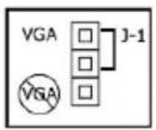
Figure 1: Display controller VGA Jumper, VGA enabled

Note: To use multiple BarcoMed display controllers in a single computer, you need to enable VGA on only ONE of the BarcoMed display controllers and disable VGA on ALL the other BarcoMed display controllers. To use a BarcoMed display controller with a third party VGA controller or with one or more Barco MXRT display controllers, do NOT enable VGA on the BarcoMed display controller.
Which PCI/PCIe slot to use
The table on the preceding page lists the different display controller model(s) available for your BARCO CORONIS 5MP Display System and the recommended PCI/PCIe slot to use for optimum performance. Figure 2 shows the different types of PCIe slots that can be used.
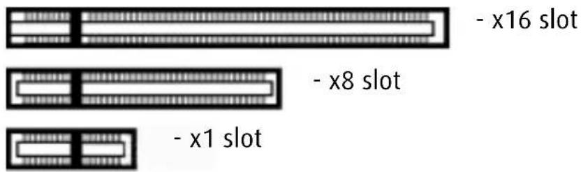
Figure 2: Examples of PCIe slots
Figure 3 shows the two different types of PCI slots that can be used.
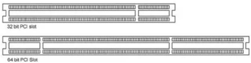
Figure 3: Examples of PCI slots
Installation Procedure
The following instructions will take you step by step through the installation of the display controller(s) for your BARCO CORONIS 5MP Display System

Caution: Wear a grounded, protective ESD strap when handling or during installation of the display controller. Electrostatic charges can damage the display controller.
- If you are not going to use your old graphics card, uninstall the drivers and software for it if you have not already done so.
- Turn off the computer, display(s), and other peripheral devices.
- Unplug the computer's power cord and disconnect all cables from the back of your computer.

Caution: Wait approximately 20 seconds after unplugging the power cord before disconnecting a peripheral or removing a component from the motherboard to avoid possible damage to the motherboard.
- Remove the computer cover.
If necessary, consult your computer's manual for help in removing the cover.
- If necessary, unscrew or unfasten and remove any existing graphics card(s) from your computer.

Note: If you are using a motherboard containing an on-board graphics solution and do not intend to use it as part of a multiple-display setup, disable it either in the computer's System Set-up utility (BIOS) or the Windows device manager.
-
Locate the appropriate slot and, if necessary, remove the metal back-plate cover(s).
-
Align the display controller(s) for your BARCO CORONIS 5MP Display System with the slot(s) and press it(them) in firmly until the card(s) is(are) fully seated.

Note: The next step applies only to the MXRT 5100, MXRT 7100, and MXRT 7200.
- Connect the power cable(s) to the 6-pin power connection(s) on the graphics card. Make sure the cables are not interfering with anything inside the computer (for example, a cooling fan).
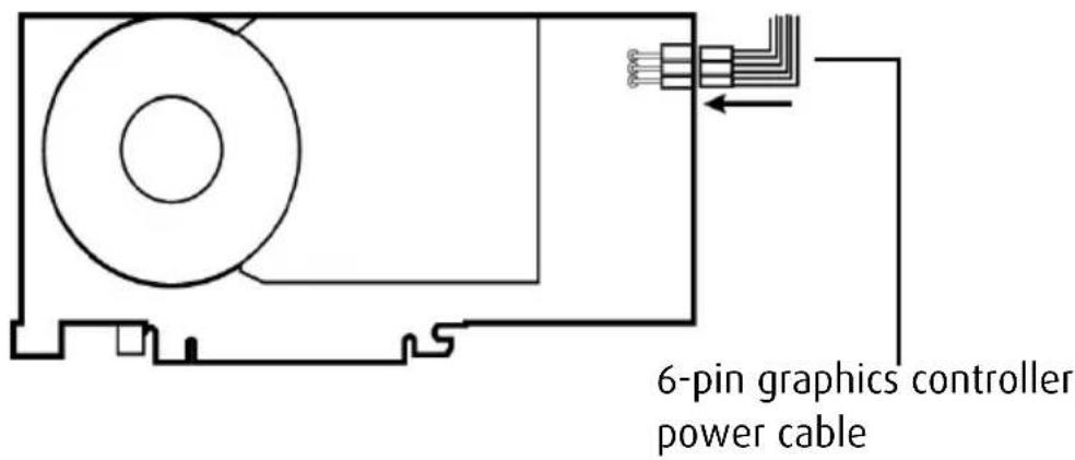
Figure 4: Power connection for the MXRT 5100, 7100, & 7300 controllers
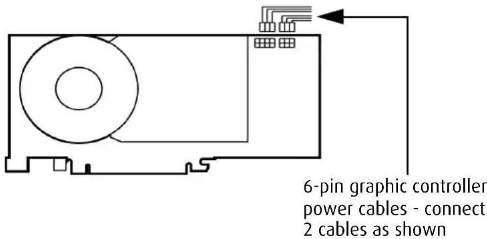
Figure 5: Power connection for the MXRT 7200 controller
-
Screw in or fasten the display controller securely. Replace and secure the computer cover.
-
Connect your Coronis 5MPs to the display controller(s) for your BARCO CORONIS 5MP Display System using the cables supplied. Make sure all cables are securely connected before turning on your system. Figures 6 - 10 show the types of connections are available:
Connecting your Barco displays
For a detailed description of the display installation and signal connection, please refer to the "Display installation" section of this manual.
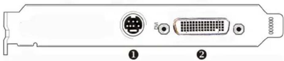
Figure 6
IO-Panel for the Barco MXRT 1150 and Barco MXRT 2150
| 1 | S-Video ConnectionThis option is not supported by Barco. |
| 2 | DMS-59 connector provides DVI-I / Head 1 & Head 2 output connections through included Y adaptor cable. |
natural_image
Back panel diagram showing two connected electronic devices with D-sub and GND connectors, labeled ① and ② (no text or symbols beyond labels)Figure 7
IO-Panel for the Barco MXRT 2100 and Barco MXRT 5200
| MXRT 2100 MXRT 5200 | |||
| 1 | Head 2- DVI-I Connection | 1 | Head 1- DVI-I Connection |
| 2 | Head 1- DVI-I Connection | 2 | Head 2- DVI-I Connection |

Note: For 6mp, connect Head 1 to left input, and Head 2 to right input.
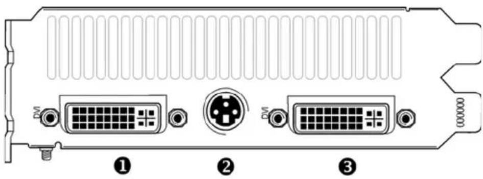
Figure 8
IO-Panel for the Barco MXRT 5100, Barco MXRT 7100 and Barco MXRT 7200
| 1 | Head 1 – DVI-I Connection |
| 2 | Stereo ConnectionThis option is not supported by Barco. |
| 3 | Head 2 – DVI-I Connection |

Note: For 6mp, connect Head 1 to left input, and Head 2 to right input.
natural_image
Back panel of a computer drive showing port, D-sub, and VGA connectors (no text or symbols visible)Figure 9
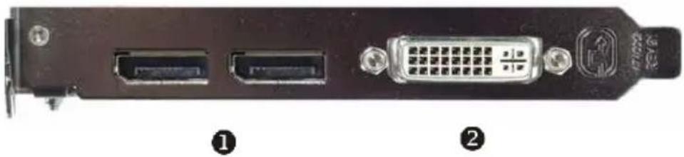
10-Panel for the Barco MXRT 7300
| 1 | DisplayPort Connections |
| 2 | DVI-I Connection |

Note: Disconnecting the DisplayPort cable may lock the display.
Note: Only two of the three connectors can be used at a time. Driving three displays is not supported with the MXRT 7300.
natural_image
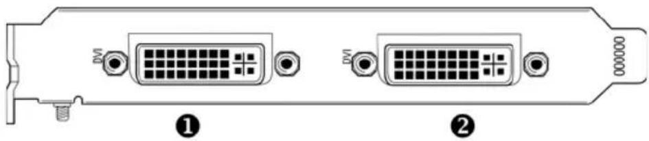
Diagram of a computer RAM module with two D-subsets and connectors, labeled ① and ② (no text or symbols on the diagram itself)Figure 10
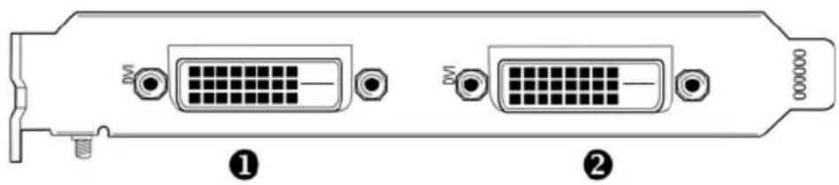
IO-Panel for the BarcoMed Coronis, BarcoMed Nio, and BarcoMed 5MP2FH family of display controllers
1 Head 1 - DVI-D Connection
② Head 2 - DVI-D Connection
- Reconnect any cables you have disconnected and plug in the computer's power cord.
- Turn on the display(s) and then your computer.
Turning on your system

WARNING: Wear a grounded, protective ESD strap when handling or during installation of the display controller. Electrostatic charges can damage the display controller.
If you have properly installed your graphics card, the Windows start-up messages will appear once the boot procedure is finished.

Note: Your Barco display(s) will be running in a basic video mode at a default refresh rate. Higher resolutions and refresh rates, such as 1536x2048@60Hz, are not available at this stage of the installation. Once you have installed the BARCO CORONIS 5MP Display System drivers and software, the Barco monitor Plug and Play software should automatically set the resolution for the displays.
- Install the drivers, QAWeb software and documentation for your BARCO CORONIS 5MP Display System by following the
instructions in the Driver and Software Installation section of this manual.
natural_image
Medical consultation scene with three doctors in white coats examining chest X-rays (no visible text or symbols)Display Installation
(This page intentionally left blank.)
Overview
Introduction
The MFGD 5421, BARCO's 21" 5 megapixel grayscale LCD display, guarantees perfect image quality in medical imaging applications.
The display combines a TFT (thin film transistor) liquid crystal display panel structure and a built-in backlight with inverter for a better picture quality. It is designed to meet the users' needs for performance, consistency, and outstanding image quality through a streamlined development process.
The display can be used in portrait or landscape version, simply by turning the panel. The tilt & swivel foot allows ideal positioning of the panel, in height and viewing angle.
The panel can be adjusted by means of a control wheel on the display.
I-Guard
I-GUARD ^ is Barco's patent-pending, built-in calibration device, continuously maintaining image quality. With I-GUARD ^ , QA checks no longer need to disturb normal radiology activities, as they can be performed while applications are running.
I-GUARD® allows radiologists or QA administrators to calibrate their viewing stations or adjust the panel's curve to DICOM standards without administrator intervention.
Power saving (DPMS)
The MFGD 5421 is equipped with a power saving system. When left idle for a certain time, the computer connected to the display, will power down the display. The power saving system can be switched on or off using the on-screen menus. This system requires a computer imaging board that supports power saving management.
Package contents
The package should include the following items, please check. If some of the items are missing, please contact the reseller from whom you have purchased the unit.
• The MFGD 5421 display
• P o w e r s u p p l y
• DVI cable
- Two velcro strips to bind the cables
• European power cord
• American power cord
- Chinese power cord
- This user manual
If the display is part of a Coronis system, the package contains more items.
Controls and connectors
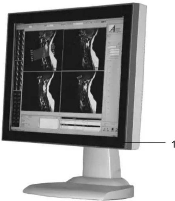
natural_image
Computer monitor displaying medical imaging scans with grid overlay and measurement tools (no readable text or symbols)Figure 11
Front
(1) Power LED
• The LED is off when the display is off.
- The LED is green when the display is on (when enabled in the on-screen menus).
- The LED is orange when the display is in Stand-by power-saving mode.
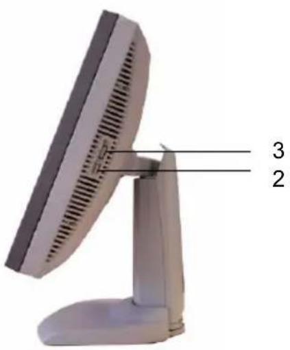
Figure 12
Side
(2) USB downstream connector
(3) Control wheel for navigating through the on-screen display (OSD) menus and changing values in the menus
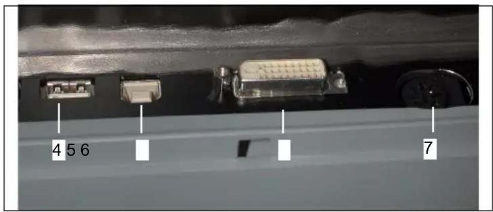
Figure 13
Rear
(4) USB downstream connector
(5) USB upstream connector
(6) Digital DVI (video and data) input
(7) DC 12V power input
Installation
Precautions
- Keep your original packaging. It is designed for this display and is the ideal protection during transport.
- Avoid reflections in the flat panel to reduce eye strain.
- Place the display on a strong and stable table or desk.
- Keep the display away from heat sources and provide enough ventilation in case it is built in a rack or console.
- Make sure all equipment is switched off before connecting the signals.
Before installing the display
Important:
In the factory, the height-positioning system in the display foot is blocked with a clip to prevent damage during transportation.
Before installing the display, you must remove this clip.
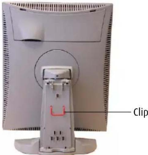
Figure 14
To remove the clip:
- Position the display with its rear side facing you.
- Lift up the 2 clips of the foot cover to release the cover from the foot.
- Pull the lower side of the cover towards you and simultaneously slide the cover downward.
- Pull the red clip out of the fixation holes in the foot.
You can better leave the cover off the foot while connecting the signal cables to the display.
Portrait or landscape position
You can change the orientation of the panel at any time, but it is more convenient to select landscape or portrait orientation before connecting the cables.
To change the panel orientation:
- Stand at the front side of the panel and take the panel at both sides.
- Very important: Tilt the panel before changing the orientation.

natural_image
Computer monitor with side-mounted ventilation slots and a stand, shown in angle with arrows indicating rotation (no text or symbols visible)Figure 15
Should you change the panel orientation without tilting it first, you might irreversibly damage the tilt & swivel mechanism.
-
To change from portrait to landscape, turn the panel counterclockwise while tilting it slightly.
-
To change from landscape to portrait, turn clockwise.
Connecting the cables
To get access to the connectors, open the cover of the connector compartment by pulling down the 2 clips of the cover.
The signal cables can be routed inside the display foot. Therefore, remove the foot cover before connecting the cables (see "Before installing the display").
To connect DVI cables:
- Connect one end of the DVI cable to the DVI input (6) of the display.
- Connect the other end of the DVI cable to the video output of your DVI signal source.
- Route the cable so that it enters the connector compartment at the place where the cover is bulged.
To connect the power:
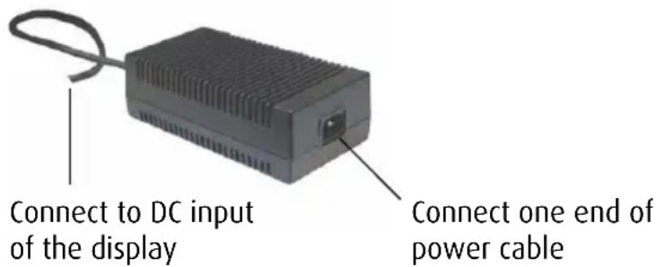
Figure 16
- Connect the output of the 12V DC power supply to the DC input (7) of the display.
- Connect one end of the proper power cable to the AC input of the 12V DC power supply.
- Connect the other end of the power cord to a grounded power outlet.
- Route the cable so that it enters the connector compartment at the place where the cover is bulged.
Routing the signal cables
After connecting all cables, fix them in the cable tie at the rear of the connector compartment. Bind the cables together above and under the foot, by means of the 2 velcro strips included in the package.
After fixing the cables, put the connector compartment cover back in place. Pay attention that the signal cables are positioned under the bulge in the cover.
Next, fix the cables in the plastic clamps on the foot. At last, put the foot cover back in place.
To put the foot cover in place:
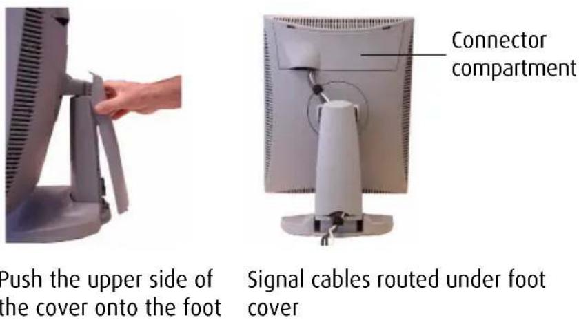
Figure 17
- Push the upper side of the cover onto the foot, so that the hooks on the cover are positioned right under the holes in the foot.
- Slide the cover upward while moving the lower side of the cover towards the foot.
- Press the cover to the foot so that both clips make a clicking sound.
Using the USB hub
The USB interface inside the display allows you to connect USB devices, such as a keyboard, mouse or digital camera, to the display.
To use the USB hub:
- Connect the display's USB upstream connector (5) to the USB port of the PC.
- Connect any USB device to any of the display's USB downstream connectors (2) or (4).
Tilt and swivel positioning
Adjust the position of the panel for best viewing conditions.
The display foot allows adjusting the horizontal viewing angle, vertical viewing angle and panel height.
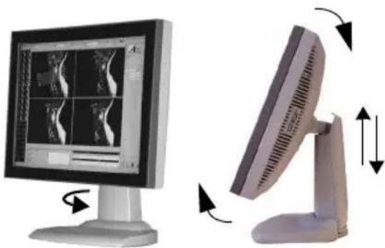
natural_image
Two computer monitors displaying medical imaging scans, one with rotation arrow and the other with bidirectional arrows (no text or symbols)Figure 18
Starting up
Proceed as follows:
-
Switch on the signal source (E.g., PC).
-
If necessary, select a suitable resolution or signal format for the signal source.
How to avoid image retention
Image retention (image sticking, ghost image) is the phenomenon where an image, or a part of it, seems to be 'burnt' in the LCD panel. When you display e.g. a uniform light gray image you distinguish the ghost image in the background.
This phenomenon occurs on all types of LCD panels when a static image remains on the screen for a long time (unfortunately the exact period is not predictable). Also parts of the image that do not change often (e.g., toolbars, buttons, borders) are susceptible to image retention.
Image retention may be undone in some cases, but it may also damage the LCD panel permanently. So it is better to take precautions during product installation to avoid it.
Here are some countermeasures you can take:
Power off, power save mode, screen saver
Very important is to use screen savers and power saving modes as much as possible. If you do not need the display for a few hours, switch it off. If you only need to look at it when you actually do something on the screen, use a screen saver.
The amount of “relaxation” time should be considerable, the more you do it the better. “Flashing” the screen for a few seconds with a screen saver is not sufficient. Image retention is a slow process to build up, but it also disappears slowly.
Re-Layout
In most applications, a display is used to show a layout of several components with borders. Whereas the content in these windows can change continuously, the borders are static images and may cause boundary image retention. The layout of the windows (size, number of windows, etc.) should be changed as much as possible.
To activate appropriate screen saving, proceed as follows:
- In the display OSD menus, open the Settings menu and switch DPMS on. For more information, please consult the display operation chapter.
- In Windows, open the Display control panel. Open the Screen Saver tab.
- Select a screen saver from the Screen saver drop-down box.
- Set the Wait time to 10 minutes.
- Click the button Power... The Power Options Properties dialog opens.
- In the Turn off monitor drop-down box, select After 20 mins.
- Click Apply.
- Close the control panel.
natural_image
Medical consultation scene with three doctors in white coats examining chest X-rays (no visible text or symbols)Software Installation
(This page intentionally left blank.)
This chapter will guide you through the installation of the drivers, software and documentation associated with your BARCO CORONIS 5MP Display System or Coronis 5MP(s).
The process for the BARCO MXRT family of controllers and BARCOMED family of controllers is handled separately.
If you install Barco displays without Barco display controllers, no drivers will be installed. Only the online user manual will be installed on your system.
Driver and software installation prerequisites

Note: To install or remove the drivers, software, or documentation you must be logged on as a user with administrator privileges.
Your operating system must be installed and running before you can install the driver, software and documentation for the display controller(s) for your BARCO CORONIS 5MP Display System.
Before you begin make sure that all of your Coronis 5MP(s) are connected to the appropriate display controller(s) in your system.

Note: This installation procedure is based on operating Windows in "Classic" view style. If "Home" or "Default" view style is selected in Windows, sections of this procedure may be different than what is listed.
Installing the BARCO MXRT drivers and software

Note: The installation dialog will display in English if your operating system's language is not supported.
This process applies to the following versions of Windows:
- Windows XP Professional,
- Windows XP Professional x64 Edition,
- Windows Server 2003,
- Windows Server 2003 x64 Edition,
- Windows Server 2008,
- Windows 2008 x64, and
- Windows Vista 32 & 64 Bit Edition.
You will need to install the Coronis 5MP system drivers and software in the following cases:
- After you have installed the display controller(s) for your BARCO CORONIS 5MP Display System in your system for the first time.
• After you have reinstalled or upgraded your operating system. - After you have moved the display controller(s) to a different PCI/PCIe slot.
- When you upgrade to a newer version of the MXRT driver.
-
When you put additional MXRT display controllers in your system.
-
You do not need to manually uninstall an existing driver before updating to the current version. The Barco Product Installation Wizard will detect any prior installations and start the uninstallation process automatically.
Start your system. When the Found New Hardware Wizard comes up, click Cancel. When the System Settings Change window asks you to restart your computer, click No or Restart Later.
- Run the Barco Product Installation Wizard.
The Barco Product Installation Wizard should start automatically when you insert the BARCO CORONIS 5MP Display System Installation CD-ROM into your computer's CD/DVD drive after the operating system has started. If your CD/DVD drive's auto-run is not enabled or the Barco Product Installation Wizard does not start automatically, you can run the Barco Product Installation Wizard manually by following these steps:
a) Click the Start button in the task bar.
b) Click Run.
c) Click Browse and browse to the root directory of the BARCO CORONIS 5MP Display System Installation CD-ROM and click on the file, Setup.exe, and click Open.
d) Click OK.
or
a) Browse to the root directory of the B ARCO CORONIS 5MP Display System Installation CD-ROM and double click on the file, Setup.exe.
-
Click Next twice.
-
Click Yes to accept the terms of the MediCal QAWeb Agent license agreement. The Barco setup wizard will continue with the installation only if you accept the terms of the license agreement. If you click No, the wizard will exit. Click Next.
-
Follow the wizard's on-screen instructions to complete the MediCal QAWeb installation.
-
The Barco Product Installation Wizard will now guide you through the installation of the driver.
-
Click Yes to accept the terms of the Barco and ATI license agreements. The Barco setup wizard will continue with the installation only if you accept the terms of both license agreements. If you click No, the wizard will exit. Click Next.
-
Follow the wizard's on-screen instructions to complete the driver installation.

Note: The driver installation may take up to 5 minutes, and the monitor may blink a few times during the installation process.

Note: For "non-English" operating systems, you may encounter multiple pop-up screens. If this occurs, click the appropriate buttons to complete the installation.
-
When the driver setup is complete, click the Finish button.
-
When the Setup complete message appears, select Reboot System Now and click Finish.
-
After the system reboots, Windows may display either the Digital Signature Not Found message or The software you are installing for this hardware has not passed Windows logo testing.
Automated display configuration
Once the drivers, software and documentation have been installed and your system has been rebooted, the Barco Monitor Plug and Play Software should automatically detect your Barco displays and attach them to the desktop with the correct resolution. If the Barco Monitor Plug and Play Software fails to detect your Barco displays or fails to attach them to the desktop correctly please refer to the section, Setting the resolution of your Barco Display in the Configuring Windows section of this manual.
Reinstalling drivers
You can install new drivers or reinstall existing drivers at any time by using the Barco Set-up wizard on your B ARCO CORONIS 5MP Display System Installation CD-ROM, see Installing the BARCO MXRT drivers and software on page 46 of this manual.
Uninstalling the drivers and software
To uninstall the Barco drivers, software or documentation for your MFGD 5421 Systems, please use the Windows Add/Remove Programs or Uninstall utility. This can be found in the Windows Control Panel. For Vista use Programs & Features.

Note: When uninstalling the Barco MXRT drivers, the dialog box shown in figure 1 will appear, and select the driver listed.
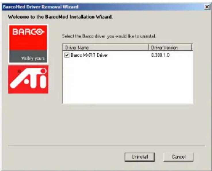
Figure 1: Barco MXRT Driver Removal Wizard (driver version may be different than what is pictured)

Note: Vista Only: After uninstalling the driver, shutdown the machine and remove the card. If you leave the card in the system, Vista will automatically reinstall the driver.
If you are uninstalling the Barco MXRT drivers prior to doing a driver upgrade, complete the Barco MXRT Driver Removal Wizard as described, and reboot the system into Safe Mode. From Safe Mode, run the Program Files\Barco\MXRT_DriverCleaner batch file to remove any remaining files. Then you can reboot into regular Windows mode to install the new driver.
Command line (Silent) Install of Drivers and Software
(Not supported with Windows Vista)
Specifying the silent install option causes most of the GUI associated with the installer to disappear. A background progress window will still be visible, but no user input will be required.
The silent install behavior is dictated by the SETUP.INI file. Each application is allowed to have separate command-line parameters for normal and silent installs.
To install the drivers and software silently, please follow the steps below:
- Insert the B ARCO CORONIS 5MP Display System Installation CD-ROM into your CD/DVD drive. When the Barco Product Installation Wizard starts click "Cancel".
- Click the Start button in the task bar.
- Click Run.
- Click Browse and
a) Browse to the root directory of the B ARCO CORONIS 5MP Display System Installation CD-ROM.
b) Click on the file, Setup.exe, and click Open.
or
a) Browse to the root directory of the location where you saved the contents of your BARCO CORONIS 5MP Display System Installation CD-ROM.
b) Click on the file, Setup.exe, and click Open.
- In the Open address window, place your cursor at the end of the line of text that appears and add the following text after Setup.exe, a space and -silent. Click OK.
Example (where D is the name of your CD/DVD drive):
D:\Setup.exe -silent
See figure 2 for an example of how the command line window should look when using the silent install from the BARCO CORONIS 5MP Display System Installation CD-ROM.
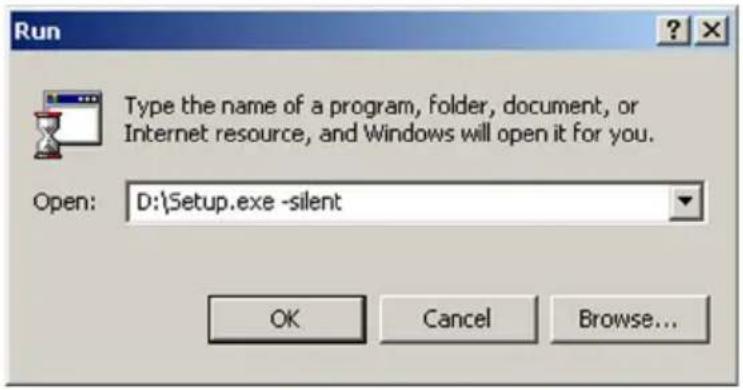
Figure 2: Command line installation

Note: When performing an MXRT driver upgrade, it is essential to uninstall the previous installation before installing the new driver. We also recommend that you perform the following steps to completely remove the previously installed files:
a) Boot the system in safe mode.
b) Run MXRT driver cleaner.bat by double clicking on it (this will either be installed as an icon on your desktop, or can be found on the Barco Display System installation CD at: drivers\2KXP\ATI). This will remove all the previous installed MXRT driver files.
c) Reboot the system in regular mode and install the new driver.
Installing the BARCOMED CORONIS or Nio drivers and software

Note: The installation dialog will display in English if your operating system's language is not supported.
This process applies to the following versions of Windows:
• Windows 2000 Professional,
- Windows XP Professional,
• Windows XP Professional x64 Edition,
- Windows Server 2003,
• Windows Server 2003 x64 Edition, and
- Windows Vista 32 & 64 Bit Edition.
You will need to install the Coronis 5MP system drivers and software in the following cases:
- After you have installed the display controller(s) for your BARCO CORONIS 5MP Display System in your system for the first time.
• After you have reinstalled or upgraded your operating system. -
After you have moved the display controller(s) to a different PCI/PCIe slot.
-
Start your system. When the Found New Hardware Wizard comes up, click Cancel. When the System Settings Change window asks you to restart your computer, click No or Restart Later.
-
Run the Barco Product Installation Wizard.
The Barco Product Installation Wizard should start automatically if you insert the BARCO CORONIS 5MP Display System Installation CD-ROM into your CD/DVD drive after the operating system has started. If your CD/DVD drive's auto-run is not enabled or the Barco Product Installation Wizard does not start automatically, you can run the Barco Product Installation Wizard manually by following these steps:
a) Click the Start button in the task bar.
b) Click Run.
c) Click Browse and browse to the root directory of the BARCO CORONIS 5MP Display System Installation CD-ROM and click on the file, Setup.exe, and click Open.
d) Click OK.
or
a) Browse to the root directory of the B ARCO CORONIS 5MP Display System Installation CD-ROM and double click on the file, Setup.exe.
- Click Next twice.
- Follow the wizard's on-screen instructions to complete the installation.

Note: When the page shown in figure 3 appears you may either click Next to accept the default settings or if you know the settings required for your viewing application, you may select them now and then click Next. You may change these settings later by accessing the Barco Driver tab within the Windows Display Control Panel.
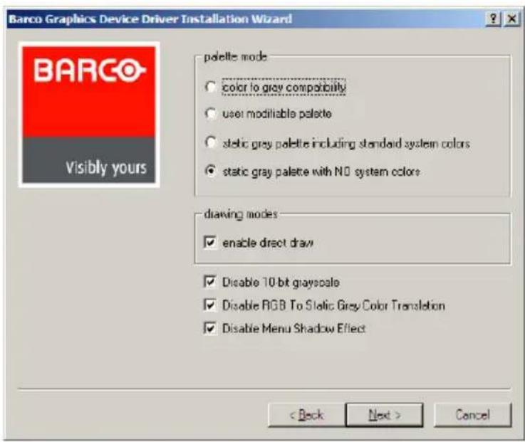
Figure 3
Please refer to your application manuals for information on the correct Palette and Drawing modes to select.
-
When the driver setup is complete, click the Finish button.
-
The Barco Product Installation Wizard will now guide you through the installation of MediCal QAWeb, BarcoMed SelfExam, and the Barco on-line documentation.
-
When the Setup complete message appears, select Reboot System Now and click Finish.
-
After the system reboots, Windows may display either the Digital Signature Not Found message or The software you are installing for this hardware has not passed Windows logo testing.
Automated display configuration
Once the drivers, software and documentation have been installed and your system has been rebooted, the Barco Monitor Plug and Play Software should automatically detect your Barco displays and attach them to the desktop with the correct resolution. If the Barco Monitor Plug and Play Software fails to detect your Barco displays or fails to attach them to the desktop correctly please refer to the section, Setting the resolution of your Barco Coronis Display in the Configuring Windows section of this manual.
Reinstalling drivers
You can install new drivers or reinstall existing drivers at any time by using the Barco Set-up wizard on your B ARCO CORONIS 5MP Display System Installation CD-ROM, see Installing the BARCOMED CORONIS or Nio drivers and software on page 52 of this manual.
Uninstalling the drivers and software
To uninstall the Barco drivers, software or documentation for your MFGD 5421 Systems, please use the Windows Add/Remove Programs or Uninstall utility. This can be found in the Windows Control Panel. For Vista use Programs & Features

Note: If you installed your BARCOMED CORONIS or Nio drivers with DualView enabled, the wizard will warn you that DualView must be disabled before the drivers can be uninstalled. This is normal, please follow the prompts from the wizard.
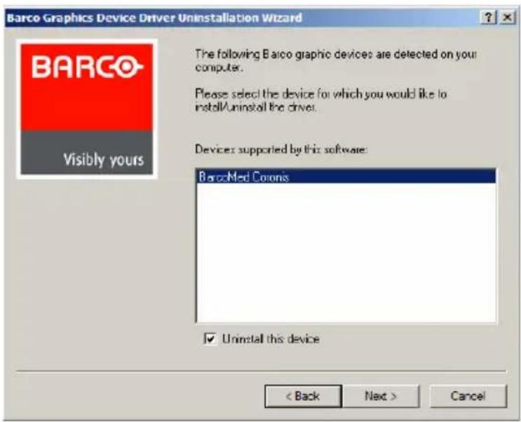
Figure 4: Barco Driver Removal Wizard
Command line (Silent) Install of Drivers and Software
(Not supported with Windows Vista)
Specifying the silent install option causes most of the GUI associated with the installer to disappear. A background progress window will still be visible, but no user input will be required.
The silent install behavior is dictated by the SETUP.INI file. Each application is allowed to have separate command-line parameters for normal and silent installs.
To install the drivers and software silently, please follow the steps below:
-
Insert the B ARCO CORONIS 5MP Display System Installation CD-ROM into your CD/DVD drive. When the Barco Product Installation Wizard starts click "Cancel".
-
Click the Start button in the task bar.
-
Click Run.
- Click Browse and
a) Browse to the root directory of the B ARCO CORONIS 5MP Display System Installation CD-ROM.
b) Click on the file, Setup.exe, and click Open.
or
a) Browse to the root directory of the location where you saved the contents of your BARCO CORONIS 5MP Display System Installation CD-ROM.
b) Click on the file, Setup.exe, and click Open.
- In the Open address window, place your cursor at the end of the line of text that appears and add the following text after Setup.exe, a space and -silent. Click OK.
Example (where D is the name of your CD/DVD drive):
D:\Setup.exe -silent
See figure 5 for an example of how the command line window should look when using the silent install from the BARCO CORONIS 5MP Display System Installation CD-ROM.
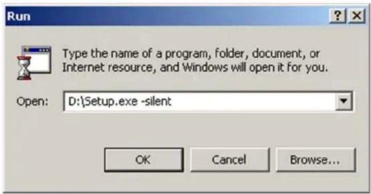
Figure 5: Command line installation
natural_image
Medical consultation scene with three doctors in white coats examining chest X-rays on a computer monitor (no visible text or symbols)Display Controller Tools
(This page intentionally left blank.)
This chapter describes how to configure the displays in your BARCO CORONIS 5MP Display System using the tools available through the Advanced button on the Settings tab of the Windows Display Control Panel.

Note: If you purchased Barco Medical Displays only and not a complete BARCO CORONIS 5MP Display System you will need to refer to the user manual for the display controller you are using.
Languages supported
The BarcoMed tabs support the following languages:
English (U.S) (default)
Dutch
French
German
Italian
Japanese
Korean
Simplified Chinese
Traditional Chinese
Spanish

Note: To change between the languages select the correct region via the Regional Settings Control Panel in your machine's Start > Settings > Control Panel.
Barco Driver Properties
Accessing the Barco tab

Note: You must have logged on to Windows using an account with administrator privileges in order to use the Barco portions of the Windows Display Control Panel to change any display settings.
- Open the Windows Display Control Panel by one of the methods below:
a) Start > Settings > Control Panel > Display
b) Open the "Display Properties Control Panel" by right clicking in an empty area on the desktop, then select Properties.
c) Windows Vista: Right click in an empty area on the desktop, select "Personalization", then click on "Display Settings".
- Click on the Settings tab (The Settings tab is not present in Vista).
- Select the rectangle that represents the Coronis 5MP whose settings you wish to change.
- Click on the Advanced Settings button.
- Select the Barco tab from the Properties screen.
Using the Barco tab
The Barco tab is divided into three sections. The first section provides information about the graphics controller and allows access to the graphics controller advanced configuration pages. The second section provides information about the display. The bottom section allows access to two Barco tools, Barco System Report and MediCal QAWeb. Also, there is a active link to the Barco Medical Imaging Systems web site.
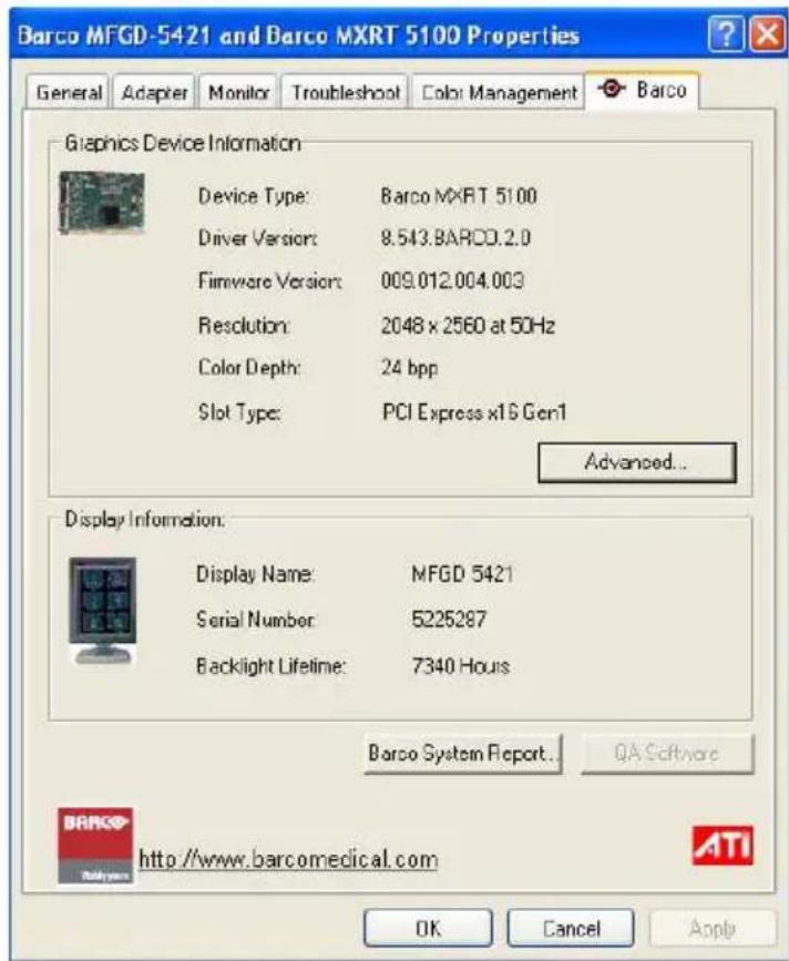
Figure 1: Ex. Barco Tab
Display Information
Name: Displays the model name of the display.
Serial Number: Displays the serial number of the display.
Backlight LifeTime: This is the amount of time in hours that the backlight has been on. The backlight will typically last a very long time, but will only be able to hold the recommended calibrated luminance for a certain amount of time, after which time it will become slowly dimmer.
Barco system report
The Barco System Report, also known as BarcoMed SelfExam, is a wizard based tool which collects data about the components that are installed in your system. This information is used by the Barco MIS Support team when trying to resolve customer issues.
MediCal QAWeb
Clicking on the QA Web button will launch the MediCal QAWeb application. Please refer to the MediCal QAWeb manual for information about this application.
Advanced properties for MXRT controller
To access the advanced properties configuration pages for the display controller(s) for your BARCO CORONIS 5MP Display System, click on the Advanced button in the Graphics Device Information section.
There are several pages accessible from the advanced configuration button. They are:
- Barco Adapter Configuration
- OpenGL
- Direct3D
- Rotation (when supported)
- Details
- OpenGL Profiles
Barco Adapter Configuration
The Barco Adapter Configuration page allows you to switch between the following monitor configurations and display options for the displays connected to a Barco MXRT controller:
Display Layout
- DualView
Both displays are enabled independent of each other. - SingleView
A single large desktop spans across both displays. - clone
The primary display is cloned to the secondary display.
Color Format
• 24-Bit TrueColor Mode
• 30-Bit TrueColor Mode (HDR)
Display Resolution
Sets display resolution for 1 or 2 displays.

Note: To switch out of SingleView or Clone mode, the buttons in this Control Panel page must be used. The main Windows Control Panel cannot be used. Depending on your system, certain configurations can be disabled.

Note: Clone Mode is supported for two color displays or projectors in 32bpp. Clone mode is not supported on grayscale displays. Also, HDR is not supported while in Clone Mode.
When choosing Clone Mode under the Barco Adapter Configuration page, if two displays are enabled, then the larger of the two current resolutions will be used. If only one of the two displays is enabled, the enabled display is current resolution will be used.
When the resolution set for clone mode is larger then the maximum supported on a display, the resolution set on the Master will automatically be scaled to maximum resolution of the Cloned display. If the Scale to Display Preferred Mode is checked, the maximum resolution will be the EDID preferred mode. If it is unchecked, then it will be the largest mode in the Cloned displays mode list. Clone mode can only be exited through the Barco Adapter Configuration page in the Barco Advanced Control Panel.

Note: Not all options are available at all times. Please select the help tips in the driver software for more information.
OpenGL and Direct3D
The OpenGL and Direct3D pages of the Advanced Properties page are divided into two sections: Main Settings and Custom Settings.
Main Settings
In the Main Settings section there is a slider bar which allows the user to adjust the OpenGL or Direct3D settings for optimum performance, optimum quality or for a point in between. There is also a checkbox provided for enabling Custom Settings.
Custom Settings

Note: Barco recommends that you use the default settings, unless your viewing application vendor provides detailed information on custom settings.
In the Custom Settings section the user can fine tune the following options:
- Anisotropic filtering
- SMOOTHVISION
- Wait for Vertical Sync
Antisotropic filtering
Anisotropic filtering is a technique that preserves detail on surfaces that have three-dimensional perspective and fade away into the background. It works best when used in conjunction with Mipmapping.
Anisotropic filtering can be set to favor either an increase in system processing performance or improved image quality.

Note: If you are unsure how to configure anisotropic filtering, use the Application Preference option. Your display will automatically adjust to the application's requirements.
Please refer to the on-line help (click on the “?” in the control panel’sOpenGL tab) for more information on using advanced features such as Anisotropic Filtering.
SMOOTHVISION
The Advanced Settings tab enables you to apply ATI's SMOOTHVISION technology for full-scene anti-aliasing. SMOOTHVISION improves image quality by removing jagged
edges (anti-aliasing) from 3D images, resulting in smoother, more natural looking objects.
Please refer to the on-line help for more information on using advanced features such as SMOOTHVISION.
Wait for Vertical Sync
- For OpenGL the default setting is Default Off.
- For Direct3D the default setting is Application Preference. Please refer to the on-line help for more information on using advanced features such as Wait for Vertical Sync.
Rotation
The Rotation page is visible only when the display connected to the current (active) head of your Barco MXRT display controller does not support rotation internally. The Rotation feature allows the user to rotate the Windows desktop to match the physical orientation of the display.
(Device) Details
The Details page provides detailed information about the display controller connected to the active display. This information is useful in debugging issues that may occur when using your Coronis 5MP(s).
OpenGL Profiles
The Configuration page enables you to customize display profiles for individual applications. Typically, you would change these settings for one or more of the following reasons:
• Diagnostic purposes.
- Fine-tuning a specific application/system configuration.
- Specific settings recommended by your hardware or software documentation.
- Tuning your application/system environment for best performance and memory usage.
Activating a configuration profile
The Configuration Profiles list box displays a number of common applications whose optimal configuration profile are factory-set by default.
To activate a particular profile, select the application name from the list and click Apply. This will add the information to the necessary Windows registry settings. If prompted, restart Windows.
If you subsequently experience problems with your application, or if you want to try to optimize the performance of your system on specific applications, modify your configuration settings accordingly.
Adding a new application profile
Click the Add button in the Configuration Profiles section and enter the name of the new application for which you want to set the configuration parameters.
Modifying the configuration parameters
To change the configuration settings of a specific application, select the name of that application from the Configuration Profiles list box. Click the Modify button. Now select or clear the rest of the configuration controls on this tabbed dialog to obtain the desired display parameters for the selected application.
To remove the selected configuration profile completely, select the name of the application from the Configuration Profiles list box and click Delete.

Note: You cannot delete the factory-set configuration profiles.
Click the Apply or OK button to enable your Configuration settings.
Advanced Properties for BarcoMed Coronis or BarcoMed Nio
Palette modes
From the Barco Drawing Modes tab you can select one of four palette modes.
• Color to Gray compatibility
- User Modifiable Color Palette
• Static Gray Palette including standard system colors
• Static Gray Palette with NO system colors
User Modifiable Color Palette
This option allows applications to modify the palette contents dynamically. As indicated in figure 2, this mode reserves the first 10 and last 10 entries in the palette for the Windows operating system, but applications can manipulate the middle 236 entries. This is the standard palette mode as configured by Windows.
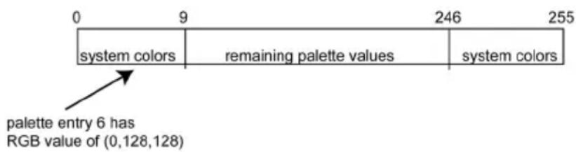
Figure 2/ User Modifiable Palette

Note: If you are unsure whether or not your application requires this "User Modifiable Color" mode, contact your application provider.
Static Gray Palette including standard system colors
This option sets the palette to be a static set of 256 gray values. Applications are denied the ability to dynamically change or allocate palette entries. This prevents palette conflicts between
applications, which can cause image color values to appear distorted in the background application.
As shown in figure 3, the 20 standard system colors are converted from RGB to gray values. The rest of the 236 entries from index 10 to 245 contain the missing gray values so that the palette has the full 256 gray values within it.
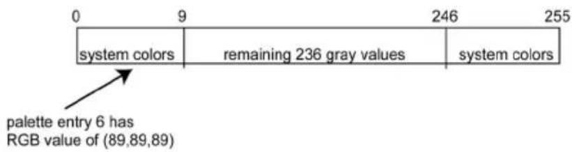
Figure 3: Static Gray Palette with system colors

Note: If you are unsure whether or not your application requires this "Static Gray Palette with System colors" mode, contact your application provider.
Static Gray Palette with NO system colors
This option sets the palette to be a static linear ramp of 256 shades of gray. Therefore, applications are denied the ability to dynamically change or allocate palette entries. This prevents palette conflicts between applications, which can cause image color values to appear distorted in the background application.
As shown in figure 4, each of the 256 entries in the palette has an RGB value of (i, i, i) where i is the index from 0 to 255.
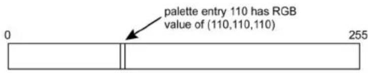
Figure 4: Static Gray Palette with NO system colors
If you wish to use a static gray palette we recommend using the "Static Gray Palette including Standard System Colors" option instead of this one. This is due to the fact that some applications assume that the first and last 10 entries of the palette are the
standard system colors. In this palette mode, these entries are made up from entries in the bottom or the top of the gray ramp.

Note: If you are unsure whether or not your application requires this "Static Gray Palette with NO System colors" mode, contact your application provider.
More information about Palette Modes is available through the on-line help.
Drawing Modes
In the Drawing Mode section you can choose from the following Drawing Modes. If any of the options in this section are grayed out, then they are not available for the model controller with which you are working.
Enable DirectDraw
This option allows the user to enable or disable DirectDraw.
DirectDraw is a software interface that provides direct access to display devices while maintaining compatibility with the Windows graphics device interface (GDI). DirectDraw is enabled by default.
More information about DirectDraw is available through the online help.
Enable Dithering
This option allows the user to enable or disable dithering.
Dithering is a technique for increasing the perceived range of colors in an image at the cost of spatial resolution.

Note: This option is only available when the User Modifiable
Palette mode is selected. If either the Static Gray Palette including Standard System Colors mode or the Static Gray Palette with NO System colors mode is selected, the "Enable Dithering" check box will be grayed-out, and dithering will be automatically disabled.
Disable 10-bit grayscale
Use this option for standard Windows®-based applications that require 8-bit color support (256 colors), such as Internet Explorer, Excel, etc.
Do not use this option for applications that require 10-bit pixel support (1024 simultaneous shades of gray) and use extended depth graphic libraries such as WinBarco.
Description of 10-bit grayscale
To show 1024 simultaneous shades of gray all BarcoMed "H" series display controllers, such as the BarcoMed 5MP2FH, BarcoMed Coronis or BarcoMed Coronis 5MP for example, run in extended depth (10-bit) mode by default.
Implications
When turned on the “Disable Extended Depth” option causes a BarcoMed Coronis display controller to run in 8-bit mode, which results in increased performance since the frame buffer is set to run with 8-bit pixels. While this option may be used with applications that normally require 10-bit support, there will be a loss of pixel depth, i.e. 256 shades of gray instead of 1024 simultaneous shades of gray.
Disable RGB To Static Gray Color Translation
Select Disable RGB To Static Gray Color Translation if you wish to have RGB values equally weighted, with 1/3 each. When not selected, then the International Commission on Illumination (CIE – Commission Internationale de l'Eclairage) model will be adapted, which weights the colors as 59% Green, 30% Red, 11% Blue.
Monitor Configuration
The Monitor configuration page allows you to switch between the following monitor configurations for the displays connected to a BarcoMed controller:
- SingleView
A single large desktop spans across both displays. - DualView
Both displays are enabled independent of each other.
Graphics Board
Update Firmware... Button: Clicking this button will launch the BarcoMed Hardware Configuration utility. This program allows the user to flash update the firmware stored in the ROM of the currently selected BarcoMed display controller. The BarcoMed Hardware Configuration utility is implemented in a Wizard format, which guides the user through the flash update procedure. The user will be prompted to select a firmware update file to use for the update process. This file will be provided by Barco Medical Imaging Systems if and when a firmware update is required.
Device Details
From the Device Details tab you can access the Device Details page, which provides detailed information about the display controller connected to the active display. This information is useful in debugging issues that may occur when using your MFGD 5421(s).
natural_image
Medical consultation scene with three doctors in white coats examining chest X-rays on a computer monitor (no visible text or symbols)Display Operation
(This page intentionally left blank.)
Operation

Operating precautions
Continuous operation of the display with the same screen may result in some image sticking on the LCD panel.
Over 10 hours operation with the same image content is not recommended.
Switching on the display DPMS may decrease the risk of image sticking (image retention).
Switching to stand-by position
When the display is on and no on-screen menus are visible, press the control wheel (3) for a few seconds to switch the display in stand-by.
When the display is in stand-by, press or turn the control wheel to switch it back on.
Controlling the display
The control wheel (3) at the bottom (landscape orientation) or at the side (portrait orientation) allows you to perform controls.
The control wheel is a rotation - click system. It provides the following functions:
- Short click: Enter menus, confirm selections, and toggle between different options
- Rotate: Browse through menus, increase or decrease adjustment values
Navigating through the menus
- The menu system has a hierarchical structure, with several levels. To display the on-screen menus, turn the wheel (3).
The Main Menu appears. This is the top level of the menu system.
MFGD 5421
MAIN MENU
Luminance
Settings
Information
EXIT
- To browse or scroll through the menus on the current level, turn the wheel clockwise or counterclockwise.
- To enter into a menu or move to a lower level of the menu structure, turn the control wheel to select the desired menu. Next, click the wheel shortly.
- To exit from a menu or move to a higher level of the menu structure, turn the control wheel to select EXIT. Next, click the control wheel shortly.
- If you do this when you are in the Main Menu, you exit the menu system.
- Some adjustments can be made by changing an adjustment value. To change an adjustment value:
- Turn the control wheel to select the adjustment
- Click the wheel shortly. The adjustment name appears, as well as the current adjustment value
- Turn the wheel to change the value
- Click the wheel shortly to confirm the change and return to the menu
- Some adjustments can be made by selecting from a range of predefined settings. To change the selection:
- Turn the control wheel to select the adjustment
- Click the wheel until the desired setting appears in the menu.
Saving changes
When you change a value, the change is automatically saved.
Setting the Luminance value
With this function, the backlight value is stabilized by the I-Guard sensor. The value you enter is the target backlight luminance, expressed in Cd/m^2 .
Proceed as follows:
- In the main menu, turn the control wheel to select the Luminance menu.
| MFGD 5421MAIN MENU |
| Luminance |
| Settings |
| Information |
| EXIT |
- Click the control wheel. The Luminance menu appears.
- Turn the control wheel to adjust the luminance target value.
- Click the control wheel to return to the main menu.
Settings
To enter the Settings menu:
- In the main menu, turn the control wheel to select the Settings menu.
| MFGD 5421MAIN MENU |
| Luminance |
| Settings |
| Information |
| EXIT |
-
Click the control wheel. The Settings menu appears.
-
Turn the wheel to select the desired menu item.
- Perform the settings as described below.
The Settings menu contains the following items:
| DPMS Click the control wheel to switch on/off the automatic power saving system (DPMS) |
| Power LED Click to switch the power LED on/off. Note: The LED's orange DPMS state is not influenced by this setting. So, when the display goes into power-saving mode, the LED will turn orange, even if it was switched off by this setting. |
| User Controls Click to disable the control wheel functions so that the on-screen display cannot be used after quitting the OSD menus.To enable the control wheel functions again:a) Do not use the wheel for at least 3 secondsb) Turn the control wheel 1 click clockwisec) Click the control wheel 2 timesd) Turn the control wheel 1 click counterclockwisee) Select the Settings menu and switch Local controls on again.Actions b, c, d have to be performed in a sequence that takes no longer than 3 seconds. |
Getting information
The Information menu allows you to get information about the display and the connected signals.
To enter the Information menu:
- In the main menu, turn the control wheel to select the Information menu.
| MFGD 5421MAIN MENU |
| Luminance |
| Settings |
| Information |
| EXIT |
- Click the control wheel. The Information menu appears. You can select to view General information or Current Input Format information.
- Turn the wheel to select the desired menu item.
- Click the wheel to select the menu item.
The Information menu contains the following items:
| Product The display type | |
| Serial No Indicates the display serial number | |
| SW Version Displays | the current internal software version |
| Display Lifetime Indicates the total time the display has been operating, including the time in stand-by | |
| Backlight Lifetime Indicates the total time the display has been operating, excluding the time in stand-by | |
Advanced functions
About this chapter
Important
The functions described in this chapter are intended for trained service staff only!
Improper use of these functions may disorder the display. BARCO cannot be held responsible for the results or damage caused by improper use of these functions.
This chapter describes only the Advanced functions in the OSD menus. For a description of the other functions (standard functions), please refer to the previous chapter, Operation.
In this chapter, we assume the advanced user knows how to use the OSD system: How to browse through the menus, how to enter menus and sub-menus, how to select and change values.
These actions are described in the previous chapter.
About the Advanced functions
The advanced functions are extensions of the OSD menus. A standard user browsing through the OSD system sees only the standard functions. When logged in in advanced mode, the user sees the standard and advanced functions in the OSD menus.
To log in as advanced user:
- Enter the main menu.
-
Turn the control wheel to select the menu item EXIT.
-
Click and hold the control wheel for a few seconds until the OSD main menu is refreshed on the screen.
| MFGD 5421MAIN MENU |
| Luminance |
| Settings |
| Information |
| Adjustments |
| EXIT |
You have now logged in as advanced user.
Advanced functions in the Luminance menu
The Luminance menu contains the following advanced function:
Manual Backlight
This function allows to manually control the backlight luminance. When you control the Manual Backlight function, the Luminance target function and I-Guard control are disabled.
Important: Disabling the I-Guard results in an uncalibrated and not stabilized backlight.
After switching the power off and on again, the Luminance target and I-Guard control are activated again. This is also the case when you control the Luminance function again.
Advanced functions in the Settings menu
The Settings menu contains the following advanced functions:
| Panel position Click to select the desired option:• Auto: Select if the display will be used in both portrait and landscape orientation.• Portrait: Select if the display is always used in portrait orientation.• Landscape: Select if the display is always used in landscape orientation. | |
| Auto Rotation When switched on, the image will be rotated automatically when switching between portrait or landscape orientation. | |
| DVI input Click to switch between normal DVI signal, Dual10 DVI signal or automatic detection of the DVI format. | |
| Stabilizer Click to switch the backlight stabilizer on/off | |
| Patch Click to hide/display the I-Guard patch.When you hide the patch, the I-Guard will not function properly anymore | |
| Burn-In Mode When switched on, the display will generate a white image when the video cable is unplugged |
Important: Disabling the I-Guard results in an uncontrolled image performance.
Advanced functions in the Information menu
In Advanced mode, the Information menu contains the following additional submenus: Service, Firmware, Runtime, Measurements and Scan Measurements.
Service
The Service information menu contains the following items:
| Display Name The display type | |
| Display Ser No Indicates the display serial number | |
| Display Stock No Indicates the display order number | |
| Panel Ser No Indicates the flat panel serial number | |
| Panel Prod Date Indicates the flat panel production date |
Firmware
The Firmware information menu contains the following items:
| Boot Code Version The | version of the internal boot code |
| Run Code Version The | version of the internal run code |
| CPLD Code Version The | version of the internal CPLD code |
| Transpose Version The | version of the internal Transpose circuit code |
Runtimes
The Runtimes information menu contains the following items:
| Display Lifetime Indicates the total time the display has been operating, including the time in stand-by |
| Backlight Lifetime Indicates the total time the display has been operating, excluding the time in stand-by (so, the total backlight lifetime) |
| Backlight Runtime Indicates the time the backlight has been on since the last time it was switched off (e.g., in stand-by). This counter is reset to 0 after 1092 minutes. |
Measurements
The Measurements info menu contains the following items:
| Internal Temperature The | temperature measured inside the display |
| Sensor Temperature The | internal temperature measured on the I-Guard board |
| FAN speed A value indicating the speed of the fans. Minimum speed is 0, maximum speed is 1000 | |
| Sensor Y value The luminance measured by the I-Guard, expressed in nit ( Cd/m^2 ) | |
| Sensor DAC value The luminance measured by the I-Guard, expressed in DAC values | |
Scan Measurements
The Scan Measurements info menu contains the following items:
| DVI Input: The current DVI input format | |
| Resolution: The resolution of the current input signal | |
| Clock Frequency: The current clock frequency | |
| Hor.Total: The total number of dots, horizontally, of the input signal | |
| Hor.Active: The number of active dots, horizontally, of the input signal | |
| Hor.Blanking: The horizontal blanking of the input signal | |
| Hor.Front Porch: The horizontal front porch of the input signal | |
| Hor.Sync: The horizontal sync length of the input signal | |
| Hor.Back Porch: The horizontal back porch of the input signal | |
| Hor.Frequency: The horizontal frequency of the input signal | |
| Vert.Total: The total number of lines, vertically, of the input signal | |
| Vert.Active: The number of active lines, vertically, of the input signal | |
| Vert.Blanking: The vertical blanking of the input signal | |
| Vert.Front Porch: The vertical front porch of the input signal | |
| Vert.Sync: The vertical sync length of the input signal | |
| Vert.Back Porch: The vertical back porch of the input signal | |
| Vert.Frequency: The vertical frequency of the input signal |
Advanced functions in the Adjustments menu
In Advanced mode, the main menu contains an additional menu, Adjustments. This menu contains the submenu Miscellaneous.
Miscellaneous Adjustments
The Miscellaneous menu contains the following items:
| RS232 Address Turn the | control wheel to change the internal display address. |
Maintenance
Panel
Take care not to damage or scratch the panel. Clean with a soft woolen or cotton towel lightly moistened with plain water.
Cabinet
Do not use chemical cleaning products, benzene, toluene, xylene or other solvents. Clean with a soft cloth dampened with mild detergent and water. Repeat with water only and wipe dry with a dry cloth.
Removing dust from the rear of the glass panel
It may be possible that dust particles have entered the display and are stuck to the rear of the glass.
We recommend to let this cleaning procedure be done in a Barco service center.
However, when really necessary, you can perform the cleaning on site if you can work in conditions that are as clean and dust-free as possible. This is to avoid more dust entering the display when opening it.
To remove the glass panel:
natural_image
Computer monitor with a stand and a curved screen, showing no visible text or symbolsFigure 5
- Switch off the display.
-
Tilt the panel.
-
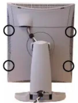
Unscrew the 4 sunken screws at the rear, fixing the glass panel and bezel.
- Unplug the cable plugged in on the bezel.
- Remove the bezel with glass panel.
Cleaning instructions:
- Dust, fingerprints, grease etc. can be removed by using a soft damp cloth lightly moistened with plain water.
- Do not apply liquid directly to the LCD surface as excess liquid may cause damage to internal electronics.
- Take care not to touch the I-guard light sensor on the LCD panel.
Troubleshooting
Windows does not show the desired display settings
Should you have problems selecting display settings for portrait oriented displays in the Windows Display Properties control panel, disable the option Hide modes that this monitor cannot display in the control panel (see below).
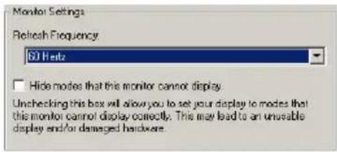
Figure 6
Information:
The display contains a special memory chip that contains information about the display's scanning capabilities. When Windows starts up, it reads the contents from this memory and presents a number of display settings in the Display Properties control panel, based on this information.
The memory of this display contains the information the display can handle scanning systems up to 120 Hz. That is why Windows will propose a display setting with a high refresh rate. However, it is best to select a refresh rate of 60 Hz.
The information that the display can be used in portrait mode, is also stored in the display memory. However, Windows does not recognize this and presents only default landscape modes if the option Hide modes that this monitor cannot display in the control panel is enabled.
Pixel Faults
Permanently dark or bright pixels can happen to TFT displays. 20 or less permanently dead pixels do not make out a good case for exchanging the unit.
Please contact our Customer Service Department if the number of pixel faults exceeds the above-mentioned figure.
Technical specifications
Picture panel
21.3-inch diagonal viewable screen TFT (thin film transistor) active matrix, greyscale liquid crystal display
Resolution
Native: 2560 x 2048
Display area (H x V)
422.4 x 337.9 (mm)
Pixel Pitch
0.165 mm (H) x 0.165 mm (V)
Viewing angle (@ 10/1 contrast)
Vertical: 85°
Horizontal: 85°
Native color resolution
8 bits / sub-pixel
Signal system
DVI dual channel
Luminance
500 cd/m2 (calibrated)
Contrast ratio
800/1 (typical, in dark environment)
Response time
25 ms (@ 25°C after 30 min warmup)
Controls
Push / turn control wheel for stand-by switching and controls
Input connectors
DVI dual channel
Power source
Input for 12 VDC power supply unit: 90 \~ 264 VAC
Input for display: 12 VDC. (The supplied 12VDC power supply must be used)
Power consumption
72 watts (max.)
Dimensions (W x H x D)
In perpendicular vertical position, highest position, tilt = 0°, swivel = 0°:
408 x 592 x 217 mm
Net weight
13.5 kg
Operating Temperature
0^ C to 40^ C
Storage Temperature
-20°C to 60°C
Humidity
(Relative, non condensing)
Operation: 8% - 80%
Storage: 5% - 95%
Due to our policy of continuous product improvement, the above specifications are subjected to change without notice. Barco shall not be liable for technical or editorial errors or omissions contained herein; nor for incidental or consequential damages whatsoever resulting from furnishing, performance or use of this material.
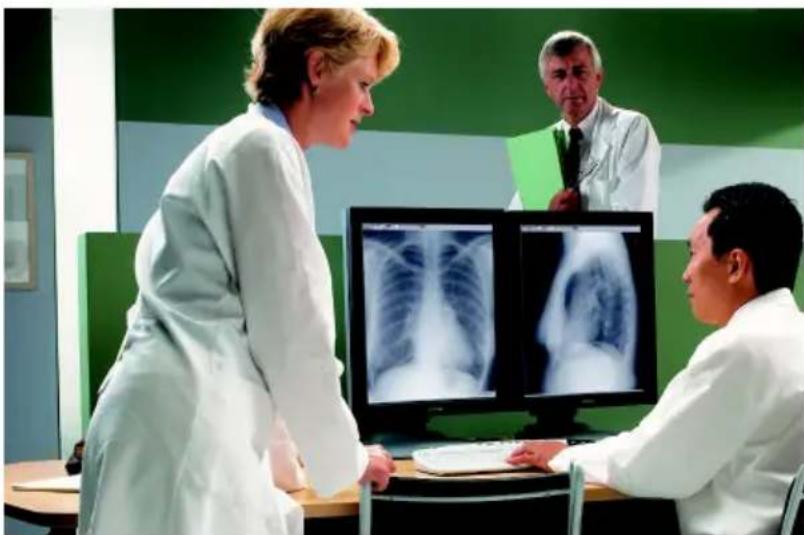
natural_image
Medical consultation scene with three doctors in white coats examining chest X-rays (no visible text or symbols)MediCal Software Installation and Operation
(This page intentionally left blank.)
MediCal Pro installation and operation
MediCal Pro software installation
Install MediCal Pro on the PC. Follow the instructions from the MediCal Pro User Guide.
Important: Do not forget you have to have Administrator privileges to install or uninstall MediCal Pro.
Using MediCal Pro
You can now use MediCal Pro to configure the complete configuration and set up the Q/A tasks.
Proceed as follows:
- Start MediCal Pro. If appropriate, you can connect to MediCal Administrator.
- Set up the configuration in MediCal Pro by using the Configuration Setup wizard.
- If necessary, align the displays' geometry settings.
- For all the displays in the system, check if the DPMS setting is turned on. Therefore, right-click on the display icon and select Properties... from the drop-down menu. Then click on Details...
Check if the Powersave option is checked. If not, check it. This is necessary to use the DPMS possibilities of the display controller. - For all the displays in the system, define (if necessary) and select a Preset.
- After selecting the Preset, MediCal Pro starts consistency calibration automatically.
-
Define the Q/A task schedule.
-
Run the due tasks.
Please refer to the MediCal Pro User Guide for more information.
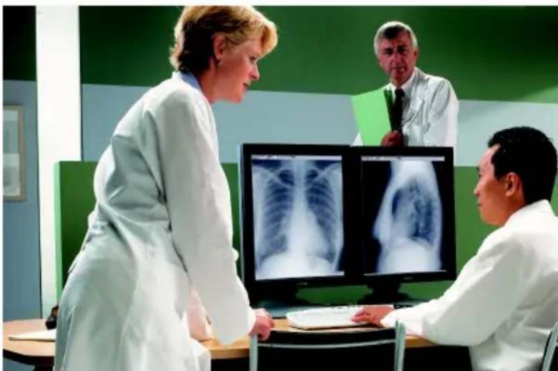
natural_image
Medical consultation scene with three doctors in white coats examining chest X-rays on a computer monitor (no visible text or symbols)Troubleshooting
(This page intentionally left blank.)
Setting the resolution of your CORONIS 5MP display

Note: In order to set the resolution of your CORONIS 5MP you must be logged in using an account with administrator privileges.
Accessing the Windows Display Control Panel
- Open the "Windows Display Control Panel" by one of the methods below:
a) Start > Settings > Control Panel > Display
b) Open the "Display Properties Control Panel" by right clicking in an empty area on the desktop, then select Properties.
c) Windows Vista: Right click in an empty area on the desktop, select "Personalization", then click on "Display Setting".
- Click on the Settings tab (the Settings tab is not present in Vista).
- Select the rectangle that represents the Barco display whose settings you wish to change.

Note: If you are using the VGA capabilities of your BARCOMED display controller, the resolution for the first display may be set to a VGA resolution of "640 x 480" pixels with 16 colors and a default refresh rate. If your BarcoMed controller is not running VGA, the display may not be enabled yet. To enable the display, check the "Extend my Windows desktop onto this monitor" checkbox, but do NOT click the Apply button at this time.
If you installed your BARCO CORONIS 5MP Display System drivers in SingleView mode (default for Windows 2000) there will be one rectangle for the virtual display representing the two heads controlled by each BarcoMed display controller output.
If you installed your BARCO CORONIS 5MP Display System drivers in DualView mode (default for Windows XP) there will be a rectangle representing each head controlled by each output of the display controller. This will be true even if you have only one
display connected to your BarcoMed controller. Both displays of a display controller cannot be enabled at the same time unless their display properties match. If necessary detach the second display of the BarcoMed display controller you are working with by right clicking on the rectangle that represents it, deselect Attached and click the Apply button.

Note: Since Windows will not let you detach the primary display connected to a particular controller, you may need to temporarily make another display the primary display
- For the display which is still attached click Click on the Advanced Button.
- Select the Adapter tab and then click on the List All Modes button. Select the resolution and refresh rate that your Coronis 5MP display supports from the dialog box and click OK.

Note: In the Adapter box, the Adapter string shows if this display is the First View or the Second View attached to the display controller. Please make a note of this, so that you can arrange the displays in the correct order later if necessary.
- Click OK on the bottom of the Adapter Control Panel. If the "OK" button on the bottom of the Adapter Control Panel is not visible, press the TAB key once and then press CTRL+Enter to select OK.
- Click OK in the "Windows will now apply your new desktop settings" dialog box. Your Coronis 5MP display should now synchronize and display the Windows desktop.
- Click Yes when asked, "Your desktop has been reconfigured. Do you want to keep these settings?"
To set the resolution of the second display attached to the BarcoMed display controller you are working with, go back to the "Settings" tab of the "Display Properties Control Panel". If necessary attach the second display you detached in step 2 above, by right clicking on the rectangle that represents it and selecting Attached.
Now repeat steps 5-8 above for this display.
If you are using a Quad-Head Configuration repeat all of the above steps for the two displays on the second display controller.

Note: If you have a single display configuration and you have enabled DualView, Windows will not allow you to attach the second head. This is normal and not a bug.
After enabling DualView and setting the resolutions in a Quad-Head Configuration you may need to drag the heads into the proper position in the window on the "Settings" tab, so that the arrangement in the window on the "Settings" tab matches the physical arrangement of your configuration.
Setting the Color and Palette Modes
(See Barco Controller Control Panel Settings section in this manual)
Configuring the Windows desktop

Note: In order to configure the Windows Desktop of your BARCO CORONIS 5MP Display System you must be logged in using an account with administrator privileges.
If you are using a color display in conjunction with your Barco grayscale display(s) you should configure your desktop before setting the resolution of the your Barco grayscale display(s).
(This page intentionally left blank.)
BARCO MID GENERAL WARRANTY TERMS AND CONDITIONS
Applicable from Jan 1st 2008
ARTICLE 1: PRODUCT WARRANTY
Barco nv, Medical Imaging Division warrants that the equipment will be free of defects in workmanship or material for the warranty period or the specific period of a warranty extension program.
Hardware: Barco warrants that upon delivery hereunder the Products shall (i) conform to its specifications in effect at the date of delivery and (ii) be free from defects in material and workmanship (the "Warranties").
Software: Barco warrants that software written by Barco shall perform substantially in accordance with the specifications in effect at the date of delivery. Software is inherently susceptible to bugs and errors. Barco makes no warranties with respect to the software which is provided to Customer on an "as-is" basis and does not warrant uninterrupted or error-free operation of the Products.
Unless otherwise indicated in Barco's Product manual or in the agreement between Barco and Customer, the Warranty Period shall be
(a) Hardware: 12 months commencing on the Barco date of invoice.
(b) Software: 3 months commencing on the Barco date of invoice.
Notwithstanding the provisions of clause 2, repair and replacement of defects in material and/or workmanship under this warranty shall be accomplished in our works according to the terms and conditions as set forth hereafter:
1.1
Any claim under the Warranties must be notified to Barco in writing within 8 days from the date the defect or failure has been discovered or noticed the first time. The Customer, upon the occurrence of any equipment failure, shall contact Barco nv, MID customer support centre (or an authorised service centre) by telephone, fax or e-mail and shall provide the applicable customer support person with a complete description of the problem being encountered, including the model and serial number of the equipment in which the problem has arisen.
1.2
The customer support person shall diagnose the problem experienced by the Customer and shall advise the Customer on how to proceed. Customer support may ask to return the faulty equipment or faulty subassemblies to the Barco nv, or a MID customer support centre (or an authorised service centre) for repair activities. In no event shall Customer return a defective Product or part thereof to Barco without Barco's prior written approval.
In the event the return to Barco of the defective Product is authorized by Barco, Barco shall issue to Customer an RMA (Return Material Authorization).
The Customer shall apply for an RMA number to the closest Barco nv, MID Customer support centre (or an authorised service centre) as listed at www.barcomedical.com, unless otherwise indicated.
The one-way cost of packing, transport and insurance related to shipping the alleged defective Product or part to Barco for repair or replacement shall be borne by Customer. The one-way cost of packing, transport and insurance related to shipping of the repaired or replacement Product or part to Customer shall be borne by Barco.
1.3
The Customer shall return, freight prepaid, the defective equipment or subassemblies in its original packaging with the assigned RMA number for repair to the Barco nv, MID Customer support centre (or an authorised service centre).
1.4
Replacement parts used shall be new or equivalent to new parts for the revision level of the equipment. A replacement LCD panel will be new or similar run time. The warranty period for the replacement parts will expire at the same moment as the original warranty period of the equipment. All parts replaced hereunder and returned to Barco nv, MID (or an authorised service centre) shall become the property of Barco nv, MID (or the authorised service centre).
1.5
The repaired equipment shall be returned to the Customer, by regular freight, at Barco nv, MID's charge.
1.6
Barco nv, MID will replace a product that fails within 90 days after shipment from Barco with a new one, ensuring color matching in the event of a diagnostic multi head display configuration.
Barco aims to ship the new replacement product within 2 business days after receipt of the Customers notification in writing.
ARTICLE 2: CONDITIONS PRECEDENT FOR WARRANTY AND ITEMS EXCLUDED FROM WARRANTY
A. The Warranties shall apply only to the extent the Products or any parts thereof have
(i) been transported and stored at all times in the original packaging in the conditions as specified by Barco (such as covered and secure location, minimum and maximum temperature, maximum humidity, ...) or, in absence thereof, at least in conditions consistent with generally accepted practice for this type of products;
(ii) been handled at all times in accordance with Barco's instructions or, in absence thereof, at least with the care and caution consistent with generally accepted practice for this type of products;
(iii) been installed strictly in accordance with the instructions and directions given by Barco (if and to the extent the Products have not been installed by Barco or its authorized subcontractors);
(iv) not been subject to any unauthorized access, alteration, modification or repair or attempts thereto;
(v) been at all times "normally used" for the intended purpose and operated in strict accordance with the operating instructions set forth in the operating manual of the Product in question and shall not have been otherwise misused, abused, damaged. For the purpose hereof, "normally used" shall mean a regular, ordinary and routine usage of the Product in question as intended and/or recommended by Barco;
(vi) been maintained at all times in accordance with Barco's instructions or, in absence thereof, at least with intervals and in a manner consistent with generally accepted practice for this type of products;
B. The warranty described herein shall not include the following:
2.1
Any hardware or software item procured from a source other than Barco nv, MID or their official agent or distributor and integrated by Customer or a third party into Barco nv, MID supplied equipment.
2.2
Any host configuration not explicitly supported by Barco nv, MID.
2.3
All software installed on the system, whether they are acquired from Barco nv, MID or third party. An exception is made for software delivered by Barco nv, MID that would prove to be a cause for the mal functioning of the hardware covered under this Agreement.
2.4
Normal wear and tear, use under circumstances exceeding specifications, such as use in dusty environment or under excessive temperature conditions, abuse, unauthorised repair or alternation, lack of proper configuration or maintenance, damaged or modified or removed serial number, cosmetic refurbishment.
2.5
Repair or replacement of consumables ^1 or specific parts that by definition are subject to wear and tear, including but not limited to:
a.CRT's, LCD panels
b. Backlights in diagnostic LCD displays, when the backlight run time ^2 is beyond the Guaranteed
Backlight Lifetime ^3 of that model, when used at the Factory Calibrated Luminance ^4
Eg1.
• A display is used at 8 hours/day; ie. +/-2.920hours/year
- The display system is covered with a warranty period of 5 year
- The Guaranteed Backlight Lifetime of that model is 17.000hours.
- The Factory Calibrated Luminance cannot be achieved anymore after 4 year, thus corresponding to +/-11.680hours
- Result: the backlight replacement is performed under warranty
Eg2.
• A display is used at 24 hours/day; ie. 8.760 hours/year
- The display system is covered with a warranty program of 5 year
- The Guaranteed Backlight Lifetime of that model is 17.000hours.
- The Factory Calibrated Luminance cannot be achieved anymore after 2.5 years, thus corresponding to +/-21.900 hours
- Result: the backlight replacement does not make part of the warranty coverage.
(1): 'Consumable' is a part that can be replaced by the user
(2): 'Backlight run time' is the total time that an image (including use of a screen saver) has been applied to the screen; this value can be consulted via the OSD buttons (On Screen Display).
(3): 'Guaranteed Backlight Lifetime' is the number of backlight hours during which a predefined luminance value, ie. the Factory Calibrated Luminance, will be provided by a specific diagnostic display model. This figure is printed on the Warranty certificate of each display or can be requested at your local Barco office.
(4): 'Factory Calibrated Luminance': is the typical luminance value that a specific diagnostic display model is calibrated at during the production process. This figure is printed on the Warranty certificate of each display or can be requested at your local Barco office.
c. Lamps, optical components in projectors
d. Replacement because of:
i. image retention as a result of:
- not correctly using screen saver and/or Display Power Management System (DPMS) as explained in the user manual
- prolonged operation of the display with a static image on the same screen area
ii. a number of missing pixels that is lower than the total allowable number as mentioned in the product specifications.
iii. difference in color temperature that is lower than the total allowable difference as mentioned in the product specifications
iv. difference in color temperature as a result of not using all displays of a multi-head configuration at the same rate.
v. LCD luminance uniformity that is in within the product specifications or luminance uniformity performance that is inherent to LCD technology.
Barco nv, MID does not warrant a minimum life time nor a performance of any of the consumables.
2.6
Replacement of moveable parts such as power cords, remote controls, ...
2.7
Any product disassembly and installation costs at the operation site, travel expenses and travel time to and from the operation site for the personnel in charge of the repair works and transport charges.
2.8
Any failures resulting from an accident, negligence (such as but not limited to removing or deleting system files & licensed software product files), misuse, circuit failure or any change, damage due to fire, water, thunder or lightning, power failure or fluctuation, disruption of communication lines or due to force majeure, or any reason foreign to the equipment.
2.9
Any specific services or procedures, asked for by Customer, related to verification of repaired equipment.
2.10 The evaluation cost in case of a returned product deemed functional is not covered under warranty and will be charged to the Customer, at Barco's sole discretion, based on a case-by-case evaluation.
ARTICLE 3: OBLIGATIONS OF THE CUSTOMER
Customer hereby assumes the following obligations as partial consideration for Barco nv, MID performance of its requirements under the warranty condition; failure by Customer to meet its obligations under this paragraph shall excuse Barco nv, MID's performance hereunder:
3.1
Customer shall not expose Barco nv, MID personnel to any unsafe working conditions.
3.2
Repairs to equipment under warranty resulting from improper maintenance or repair performed by the Customer, or its officers, agents, employees, or representatives, shall be borne by the Customer at its additional cost and expense.
3.3
The Customer is responsible for installing the Barco nv, MID equipment in an environment for which it was intended. If there is an indication that the equipment was used – even temporary – outside its specifications, Barco nv, MID is entitled not to perform warranty repairs and terminate the warranty agreement. Any actions that have been taken by Barco nv, MID in this respect, may be invoiced to the Customer at normal pricing.
ARTICLE 4: REMEDIES UNDER WARRANTY
(a) Hardware: If during the Warranty Period a Product or any part thereof, fails to meet any of the Warranties then, upon Customer's request, Barco shall, at its sole option and cost, promptly and within 20 working days, either: (i) repair or correct the Product or part in question; or (ii) replace the Product or supply part(s) or component(s) according to the terms and conditions contained in article 1. A replacement part shall be at least functionally equivalent to the original part. The replaced Product, parts and/or components shall become the property of Barco and shall, at Barco's request, be returned by Customer to Barco at Barco's cost.
(b) Software: Barco's sole obligation shall be to rectify substantial malfunctions of the software (to the extent technically reasonably possible) by amending the software or supplying an alternative version of the software.
(c) The repair or replacement under the Warranties covers the cost of material and labor.
ARTICLE 5: DISCLAIMER OF WARRANTIES
BARCO NV, MID DISCLAIMS ALL WARRANTIES, EXPRESSED OR IMPLIED, INCLUDING ALL IMPLIED WARRANTIES OF MERCHANTABILITY AND FITNESS FOR A PARTICULAR PURPOSE.
ARTICLE 6: LIMITATION OF LIABILITY
BARCO NV, MID SHALL NOT UNDER ANY CIRCUMSTANCES BE LIABLE TO CUSTOMER OR ANY THIRD PARTY FOR DIRECT, INDIRECT, INCIDENTAL, SPECIAL OR CONSEQUENTIAL DAMAGES, SUCH AS BUT NOT LIMITED TO, DAMAGE TO OR LOSS OF TANGIBLE OR INTANGIBLE PROPERTY OR EQUIPMENT, LOSS OF PROFITS OR REVENUES, COST OF CAPITAL, COST OF PURCHASE OF REPLACEMENT GOODS, OR CLAIMS OF CUSTOMERS OF USER FOR SERVICE INTERRUPTIONS. THE LIABILITY OF BARCO NV, MID FOR MANUFACTURING, SALE, DELIVERY, RESALE, INSTALLATION, OPERATION OR SUITABILITY FOR USE OF ANY PRODUCTS OR SERVICES COVERED BY OR FURNISHED UNDER THIS WARRANTY CONDITION, WHETHER ARISING OUT OF CONTRACT,
NEGLIGENCE, STRICT TORT, WARRANTY OR OTHERWISE, SHALL BE LIMITED TO THE REPAIR OR REPLACEMENT OF THE PRODUCT OR ANY PART THEREOF WHICH SHALL BE AT CUSTOMER'S SOLE OPTION AND COST. BARCO'S LIABILITY SHALL NOT EXCEED THE PRICE OF THE ITEM OR ITEMS OF GOODS OR SERVICES UPON WHICH SUCH LIABILITY IS BASED.
ARTICLE 7: FORCE MAJEURE
Either party shall be released from performance of its obligations under this agreement to the extent, and for so long as, the performance of this agreement is impeded by reason of force majeure. For the purposes of this clause the expression "force majeure" means, but shall not be limited to, industrial dispute, fire, mobilisation, requisition, embargo, currency transfer prohibitions, insurrection, lack of means of transport, restrictions of the use of energy, and generally any circumstances which are beyond the control of the parties and hinder performance by one party of his obligations.
ARTICLE 8: GENERAL
8.1
Customer acknowledges its understanding that all software and electronic devices, including Barco nv, MID products are subject to possible error, mechanical or electrical failure, and should not be relied upon in inappropriate applications or without proper backup and/or other safety precautions whenever personal injury or property damage may result from failure or error of the product.
8.2
Barco nv, MID shall not be responsible for machine failure and/or its failure to render service or maintenance due to causes beyond its reasonable control.
B4100523-04
November 2009
- Display Controller Installation ....17
- Display Installation.... 29
- Software Installation 43
- Display Controller Tools 57
- Display Operation ....73
- MediCal Software Installation and Operation....93
- Troubleshooting....97
- Copyright notice
- Preface
- Notice
- FCC notice
- Canadian notice
- Information for China ROHS compliance
- 中国大陆 RoHS
- General Recommendations
- Electrical shock
- Type of protection (electrical):
- Degree of safety (flammable anesthetic mixture):
- Power connection
- Water and moisture
- Ventilation
- Installation
- This apparatus conforms to:
- National Scandinavian Deviations for Cl. 1.7.2 :
- Recommendations for using your display system
- Optimize the lifetime of your display
- Use a screen saver to avoid image retention
- Understand pixel technology
- Enhance user comfort
- Maximize Quality Assurance
- Which display controller?
- Installing a Barco display controller
- Overview
- Which PCI/PCIe slot to use
- Installation Procedure
- Connecting your Barco displays
- IO-Panel for the BarcoMed Coronis, BarcoMed Nio, and BarcoMed 5MP2FH family of display controllers
- Turning on your system
- Introduction
- I-Guard
- Power saving (DPMS)
- Package contents
- Controls and connectors
- Front
- Side
- Rear
- Precautions
- Before installing the display
- Important:
- To remove the clip:
- Portrait or landscape position
- Connecting the cables
- To connect DVI cables:
- To connect the power:
- Routing the signal cables
- Using the USB hub
- To use the USB hub:
- Tilt and swivel positioning
- Starting up
- How to avoid image retention
- Power off, power save mode, screen saver
- Re-Layout
- Driver and software installation prerequisites
- Installing the BARCO MXRT drivers and software
- Automated display configuration
- Reinstalling drivers
- Uninstalling the drivers and software
- Command line (Silent) Install of Drivers and Software
- Installing the BARCOMED CORONIS or Nio drivers and software
- Languages supported
- Barco Driver Properties
- Accessing the Barco tab
- Using the Barco tab
- MediCal QAWeb
- Advanced properties for MXRT controller
- Barco Adapter Configuration
- Display Layout
- Color Format
- Display Resolution
- OpenGL and Direct3D
- Main Settings
- Custom Settings
- Antisotropic filtering
- SMOOTHVISION
- Rotation
- (Device) Details
- OpenGL Profiles
- Advanced Properties for BarcoMed Coronis or BarcoMed Nio
- Palette modes
- User Modifiable Color Palette
- Static Gray Palette including standard system colors
- Static Gray Palette with NO system colors
- Drawing Modes
- Enable DirectDraw
- Enable Dithering
- Disable 10-bit grayscale
- Disable RGB To Static Gray Color Translation
- Monitor Configuration
- Graphics Board
- Device Details
- Operation
- Operating precautions
- Switching to stand-by position
- Controlling the display
- Navigating through the menus
- MFGD 5421
- MAIN MENU
- Saving changes
- Setting the Luminance value
- Settings
- To enter the Settings menu:
- Getting information
- To enter the Information menu:
- Advanced functions
- Important
- About the Advanced functions
- To log in as advanced user:
- Advanced functions in the Luminance menu
- Manual Backlight
- Advanced functions in the Settings menu
- Advanced functions in the Information menu
- Service
- Firmware
- Runtimes
- Measurements
- Scan Measurements
- Advanced functions in the Adjustments menu
- Miscellaneous Adjustments
- Maintenance
- Panel
- Cabinet
- Removing dust from the rear of the glass panel
- To remove the glass panel:
- Cleaning instructions:
- Troubleshooting
- Information:
- Pixel Faults
- Technical specifications
- Picture panel
- Resolution
- Display area (H x V)
- Pixel Pitch
- Viewing angle (@ 10/1 contrast)
- Native color resolution
- Signal system
- Luminance
- Contrast ratio
- Response time
- Controls
- Input connectors
- Power source
- Power consumption
- Dimensions (W x H x D)
- Net weight
- Operating Temperature
- Storage Temperature
- Humidity
- MediCal Pro installation and operation
- MediCal Pro software installation
- Using MediCal Pro
- Setting the resolution of your CORONIS 5MP display
- Accessing the Windows Display Control Panel
- Setting the Color and Palette Modes
- Configuring the Windows desktop
- BARCO MID GENERAL WARRANTY TERMS AND CONDITIONS
- ARTICLE 1: PRODUCT WARRANTY
- 1.1
- 1.2
- 1.3
- 1.4
- 1.5
- 1.6
- ARTICLE 2: CONDITIONS PRECEDENT FOR WARRANTY AND ITEMS EXCLUDED FROM WARRANTY
- 2.1
- 2.2
- 2.3
- 2.4
- 2.5
- ARTICLE 3: OBLIGATIONS OF THE CUSTOMER
- ARTICLE 4: REMEDIES UNDER WARRANTY
- ARTICLE 5: DISCLAIMER OF WARRANTIES
- ARTICLE 6: LIMITATION OF LIABILITY
- ARTICLE 7: FORCE MAJEURE
- ARTICLE 8: GENERAL
- 8.1
- 8.2
Brand : Barco
Model : Coronis MFGD-5421
Category : Monitor