
GY-HM700U - Video camera JVC - Free user manual and instructions
Find the device manual for free GY-HM700U JVC in PDF.


| Product Type | Professional HD Camcorder |
| Model | JVC GY-HM700U |
| Sensor | 1/3-inch 3-CMOS |
| Recording Media | SDHC/SDXC memory cards (dual slot) |
| Video Formats | MPEG-2, H.264 (AVCHD), MXF, QuickTime |
| Lens Mount | Bayonet (interchangeable lens system) |
| Dimensions (WxHxD) | 156 x 129 x 304 mm |
| Weight | Approx. 3.4 kg (with lens and media) |
| Power Supply | DC 14.4V (battery or AC adapter) |
| Battery Type | Rechargeable Li-ion (BN-VF823 or compatible) |
| Recording Resolution | 1080p, 1080i, 720p |
| Frame Rates | 23.98, 25, 29.97, 50, 59.94 fps |
| Audio | 2-channel uncompressed PCM, XLR inputs |
| Video Outputs | HD-SDI (BNC), HDMI, Composite |
| Audio Outputs | RCA (L/R), Headphone jack |
| Inputs | Timecode (BNC), Genlock (BNC), Remote (D-sub) |
| Storage Capacity (max per card) | 512 GB (SDXC) |
| LCD Screen | 3.5-inch color (approx. 920k dots) |
| Viewfinder | 0.45-inch color (approx. 1.2M dots) |
| Maintenance | Clean exterior with dry cloth; use lens blower for optics |
| Safety | Do not expose to rain; use only specified power source |
| Spare Parts / Repairability | Contact JVC service centers for replacement parts |
Frequently Asked Questions - GY-HM700U JVC
User questions about GY-HM700U JVC
0 question about this device. Answer the ones you know or ask your own.
Ask a new question about this device
Download the instructions for your Video camera in PDF format for free! Find your manual GY-HM700U - JVC and take your electronic device back in hand. On this page are published all the documents necessary for the use of your device. GY-HM700U by JVC.
USER MANUAL GY-HM700U JVC
natural_image
Line drawing of a JVC video camera with extended lens and external frame (no text or symbols)* The illustration shows the GY-HM700E with the supplied viewfinder, microphone and lens attached.
* GY-HM700CHU/GY-HM700CHE does not come with a lens.
For Customer Use:
Enter below the Serial No. which is located on the body.
Retain this information for future reference.
Model No. GY-HM700U/GY-HM700CHU
Serial No.
Please read the following before getting started:
Thank you for purchasing this JVC product.
Before operating this unit, please read the instructions
carefully to ensure the best possible performance.
In this manual, each model number is described without the last letter
(U/E) which means the shipping destination. (U: for USA and Canada,
E: for Europe)
Only "U" models (GY-HM700CHU/GY-HM700U) have been evaluated by UL.
FOR USA
These are general IMPORTANT SAFEGUARDS and certain items may not apply to all appliances.
IMPORTANT SAFEGUARDS
- Read all of these instructions.
- Save these instructions for later use.
- All warnings on the product and in the operating instructions should be adhered to.
- Unplug this appliance system from the wall outlet before cleaning. Do not use liquid cleaners or aerosol cleaners. Use a damp cloth for cleaning.
- Do not use attachments not recommended by the appliance manufacturer as they may cause hazards.
- Do not use this appliance near water - for example, near a bathtub, washbowl, kitchen sink, or laundry tub, in a wet basement, or near a swimming pool, etc.
- Do not place this appliance on an unstable cart, stand, or table. The appliance may fall, causing serious injury to a child or adult, and serious damage to the appliance.
Use only with a cart or stand recommended by the manufacturer, or sold with the appliance.
Wall or shelf mounting should follow the manufacturer's instructions, and should use a mounting kit approved by the manufacturer. An appliance and cart combination should be moved with care.
Quick stops, excessive force, and uneven surfaces may cause the appliance and cart combination to overturn.
PORTABLE CART WARNING (symbol provided by RETAC)

S3125A
- Slots and openings in the cabinet and the back or bottom are provided for ventilation, and to insure reliable operation of the appliance and to protect it from overheating, these openings must not be blocked or covered. The openings should never be blocked by placing the appliance on a bed, sofa, rug, or other similar surface.
This appliance should never be placed near or over a radiator or heat register.
This appliance should not be placed in a built-in installation such as a bookcase unless proper ventilation is provided. - This appliance should be operated only from the type of power source indicated on the marking label. If you are not sure of the type of power supplied to your home, consult your dealer or local power company. For appliance designed to operate from battery power, refer to the operating instructions.
- For added protection for this product during a lightning storm, or when it is left unattended and unused for long periods of time, unplug it form the wall outlet and disconnect the antenna or cable system. This will prevent damage to the product due to lightning and power-line surges.
- Do not allow anything to rest on the power cord. Do not locate this appliance where the cord will be abused by persons walking on it.
- Follow all warnings and instructions marked on the appliance.
- Do not overload wall outlets and extension cords as this can result in fire or electric shock.
- Never push objects of any kind into this appliance through cabinet slots as they may touch dangerous voltage points or short out parts that could result in a fire or electric shock. Never spill liquid of any kind on the appliance.
- Do not attempt to service this appliance yourself as opening or removing covers may expose you to dangerous voltage or other hazards. Refer all servicing to qualified service personnel.
- Unplug this appliance from the wall outlet and refer servicing to qualified service personnel under the following conditions:
a. When the power cord or plug is damaged or frayed.
b. If liquid has been spilled into the appliance.
c. If the appliance has been exposed to rain or water.
d. If the appliance does not operate normally by following the operating instructions. Adjust only those controls that are covered by the operating instructions as improper adjustment of other controls may result in damage and will often require extensive work by a qualified technician to restore the appliance to normal operation.
e. If the appliance has been dropped or the cabinet has been damaged.
f. When the appliance exhibits a distinct change in performance - this indicates a need for service.
- When replacement parts are required, be sure the service technician has used replacement parts specified by the manufacturer that have the same characteristics as the original part. Unauthorized substitutions may result in fire, electric shock, or other hazards.
- Upon completion of any service or repairs to this appliance, ask the service technician to perform routine safety checks to determine that the appliance is in safe operating condition.
Safety Precautions
FOR USA AND CANADA

CAUTION
RISK OF ELECTRIC SHOCK DO NOT OPEN

CAUTION: TO REDUCE THE RISK OF ELECTRIC SHOCK. DO NOT REMOVE COVER (OR BACK). NO USER-SERVICEABLE PARTSINSIDE. REFER SERVICING TO QUALIFIED SERVICE PERSONNEL.

The lightning flash with arrowhead symbol, within an equilateral triangle is intended to alert the user to the presence of uninsulated "dangerous voltage" within the product's enclosure that may be of sufficient magnitude to constitute a risk of electric shock to persons.

The exclamation point within an equilateral triangle is intended to alert the user to the presence of important operating and maintenance (servicing) instructions in the literature accompanying the appliance.
INFORMATION:
This equipment has been tested and found to comply with the limits for a Class A digital device, pursuant to Part 15 of the FCC Rules. These limits are designed to provide reasonable protection against harmful interference when the equipment is operated in a commercial environment.
This equipment generates, uses, and can radiate radio frequency energy and, if not installed and used in accordance with the instruction manual, may cause harmful interference to radio communications.
Operation of this equipment in a residential area is likely to cause harmful interference in which case the user will be required to correct the interference at his own expense.
CAUTION:
CHANGES OR MODIFICAT IONS NOT APPROVED BY JVC COULD VOID USER'S AUTHORITY TO OPERATE THE EQUIPMENT.
NOTE:
The rating plate (serial number plate) is on this unit.
WARNING:
TO REDUCE THE RISK OF FIRE OR ELECTRIC SHOCK, DO NOT EXPOSE THIS APPLIANCE TO RAIN OR MOISTURE.
THIS DEVICE COMPLIES WITH PART 15 OF THE FCC RULES.
OPERATION IS SUBJECT TO THE FOLLOWING TWO CONDITIONS: (1) THIS DEVICE MAY NOT CAUSE HARMFUL INTERFERENCE, AND (2) THIS DEVICE MUST ACCEPT ANY INTERFERENCE RECEIVED, INCLUDING INTERFERENCE THAT MAY CAUSE UNDESIRED OPERATION.
POUR CANADA

ATTENTION
RISQUE D'ELECTROCUTION NE PAS OUVRIR

ATTENTION: POUR EVITER TOUT RISQUE D'ELECTROCUTION NE PAS OUVRIR LE BOITER.
AUCUNE PIECE INTERIEURE N'EST A REGLER PAR L'UTILISATEUR. SE REFERER A UN AGENT QUALIFIE EN CAS DE PROBLEME.

This Class A digital apparatus complies with Canadian ICES-003.
TO REDUCE THE RISK OF FIRE OR ELECTRIC SHOCK, DO NOT EXPOSE THIS APPLIANCE TO RAIN OR MOISTURE.
CAUTION:
This unit should be used with 12V DC only. To prevent electric shocks and fire hazards, do NOT use any other power source.
NOTE:
The rating plate (serial number plate) is on the unit.
REMARQUE:
To prevent electric shock, do not open the cabinet. No user serviceable parts inside. Refer servicing to qualified service personnel.
Due to design modifications, data given in this instruction book are subject to possible change without prior notice.
The apparatus shall not be exposed to dripping or splashing and that no objects filled with liquids, such as vases, shall be placed close to the apparatus.
AVERTISSEMENT:
POUR EVITER LES RISQUES D'INCENDIE OU D'ELECTROCUTION, NE PAS EXPOSER L'APPAREIL A L'HUMIDITE OU A LA PLUIE.
ATTENTION:
Safety Precautions (continued)
FOR EUROPE
This equipment is in conformity with the provisions and protection requirements of the corresponding European Directives. This equipment is designed for professional video appliances and can be used in the following environments:
- Controlled EMC environment (for example, purpose-built broad-casting or recording studio), and rural outdoors environments.
In order to keep the best performance and furthermore for electromagnetic compatibility we recommend to use cables not exceeding the following lengths:
| Port Cable Length | ||
| [DC INPUT] Exclusive Cable 5 m | ||
| [Y/VIDEO], [PB], [PR] Coaxial Cable 10 m | ||
| [AUDIO INPUT 1/2] Shielded Cable 3 m | ||
| [AUDIO OUTPUT] Shielded Cable 10 m | ||
| [PHONES] Exclusive Cable 3 m | ||
| [IEEE1394] (HD/DV) | Exclusive Cable | 3 m |
| [HD/SD-SDI] Coaxial Cable 10 m | ||
| [REMOTE] Exclusive Cable 5 m | ||
| [LENS] Unshielded Cable 0.1m | ||
| [VF] | Special Cable | 0.3m |
| [USB] | Shielded Cable 3 m | |
Caution:
Where there are strong electromagnetic waves or magnetism, for example near a radio or TV transmitter, transformer, motor, etc., the picture and the sound may be disturbed. In such case, please keep the apparatus away from the sources of the disturbance.
Dear Customer,
This apparatus is in conformance with the valid European directives and standards regarding electromagnetic compatibility and electrical safety.
European representative of Victor Company of Japan, Limited is:
JVC Technical Services Europe GmbH
Postfach 10 05 04
61145 Friedberg
Germany
Information for Users on Disposal of Old Equipment [European Union]

Attention:
This symbol is only valid in the European Union.
This symbol indicates that the electrical and electronic equipment should not be disposed as general household waste at its end-of-life. Instead, the product should be handed over to the applicable collection point for the recycling of electrical and electronic equipment for proper treatment, recovery and recycling in accordance with your national legislation.
By disposing of this product correctly, you will help to conserve natural resources and will help prevent potential negative effects on the environment and human health which could otherwise be caused by inappropriate waste handling of this product. For more information about collection point and recycling of this product, please contact your local municipal office, your household waste disposal service or the shop where you purchased the product. Penalties may be applicable for incorrect disposal of this waste, in accordance with national legislation.
(Business users)
If you wish to dispose of this product, please visit our web page http://www.jvc.eu to obtain information about the take-back of the product.
[Other Countries outside the European Union]
If you wish to dispose of this product, please do so in accordance with applicable national legislation or other rules in your country for the treatment of old electrical and electronic equipment.
FOR USE IN CHINA ONLY
Precautions for Proper Use ....5
Operation Mode 7
Names of Parts ....8
Side Control Panel....10
Viewfinder 11
LCD Monitor....11
Side Terminal .....12
SD Slot....13
Rear 13
Zoom Lens 14
Basic System Diagram 15
Displays on the LCD Monitor and Viewfinder ..... 16
Status Screen 16
Enlarged Status Display on LCD Monitor 17
Auto White Display (Camera Mode Only) 18
Menu Setting Screen 18
Alarm Display....18
Zebra Pattern Display 18
Preparations
Attaching Accessories ....19
Attaching the Zoom Lens 19
Attaching the Microphone (Supplied) 19
Attaching the Viewfinder (Supplied) .....20
Power Supply ....20
Using AC Power (DC IN Power) .....21
Using a Battery Pack....21
Turning On/Off the Power 24
Setting the Clock (Initial Setting) .....25
Adjusting the Monitor Speaker 26
Adjusting Back Focus .....27
Adjusting the LCD Monitor and Viewfinder ..... 28
Tally Lamps 30
SDHC Cards 31
Formatting (Initializing) SDHC Cards .....32
Restoring the SDHC Card ....33
Estimated Recordable Time of SDHC Cards .....33
Shooting
Basic Shooting Procedures ....34
Shooting 34
Focus Assist Function 35
Recording Clips 35
Selecting File and Video Formats ....36
Adjusting the Iris ....37
Setting Gain 37
Setting the Electronic Shutter .....38
Adjusting the White Balance 40
Adjusting the White Shading .....42
Setting the ND Filter 43
Adjusting Audio Input Settings and Recording Level .....44
Setting Audio Input 44
Adjusting Audio Recording Level .....44
Audio Monitor During Recording 45
Setting Time Code and User's Bit .....46
Displaying Time Code and User's Bit .....46
Time Code Operation Mode .....46
Presetting the User's Bit ....48
Setting Time Code Without Opening the Menu .....48
Setting User's Bit Without Opening the Menu .....49
Recording Time Code in Continuation of the Recorded Time Code on SDHC card .....49
Setting Zebra Pattern .50
Setting Spot Meter ....51
Viewing Recorded Videos Immediately (Clip Review) ....52
Assigning Functions to User Buttons .....53
Protecting Important Scenes (OK Mark Function) .....54
Special Recording ....54
Pre REC....54
Clip Continuous REC ....55
Variable Frame REC ....56
Playback
Playing Back Recorded Clips .....57
Thumbnail Screen ....57
Playing Back 61
Thumbnail Menu ....61
Deleting Clips 62
Appending and Deleting OK Marks ....64
Menu Display and Detailed Settings
Basic Operations in Menu Screen 66
Display and Description of the Menu Screen ..... 66
Text Input with Software Keyboard 67
Menu Screen Hierarchical Chart 68
Main Menu Screen 70
Record Set Menu 71
Record Format Menu 71
Rec Mode Menu 71
Clip Set Menu 72
Audio Set Menu 72
Camera Function Menu 73
Switch Set Item 74
FULL AUTO Item 75
Camera Process Menu 76
Detail/Adjust Item 78
White Balance Item 79
Shading Mode/Adjust Item 80
Color Matrix/Adjust Item 80
TC/UB Menu 82
LCD/VF Menu 82
Shooting Assist Item 83
Marker Setting Item 84
Status Display Item ....84
A/V Out Menu 86
Others Menu 87
Media Menu 89
Setup File Manage Menu 89
Adding/Editing Frequently Used Menu Items
(Favorites Menu) 90
Adding Menu Items to [Favorites Menu] 90
Editing [Favorites Menu] .....91
Status Screen
Status Screen in Camera Mode 94
Status Screen in SD Card Mode 100
Status Screen in IEEE1394 Input Mode .....102
Enlarged Status Display on LCD Monitor 103
Camera Features
Marker and Safety Zone Displays
(Camera Mode Only)....104
Smoothening the Skin Color (Skin Detail Function) .....106
Color Bar Output 107
Color Matrix Adjustment 108
Reproduction of Dark Areas
(Black Stretch/Compress Function)....110
Configuring Setup Files ....111
Saving Setup Files 112
Loading a Setup File 113
Resetting Setup Files ....113
Connecting External Devices
Connecting an External Monitor .....114
IEEE1394 Connection ....115
Backup Recording ....116
Stream Transmission to a
Non-linear Editing System .....117
Managing/Editing Clips on a PC 118
Remote Control Unit Connection .....119
List of Remote Control Unit Functions .....120
Others
Error Displays and Actions ....122
Tally Lamps 123
Alarm Tone ....123
Troubleshooting 124
Specifications....126
How to use this manual
Symbols used
Note : Describes precautions concerning the operation of this product.
Memo : Describes reference information, such as functions and usage restrictions of this product.
: Indicates the reference page numbers and reference items.
■Content of this manual
- All rights reserved by JVC. Unauthorized duplication or reprinting of this manual, in whole or in part, is strictly prohibited.
- All other product names used in this manual are trademarks or registered trademarks of their respective companies. Marks such as TM , and have been omitted in this manual.
- Illustrated designs, specifications and other contents of this manual are subject to change for improvement without prior notice.
Main Features
This camera recorder enables recording of HD format images on an SDHC card, and also playback of these images.
Recording in QuickTime File Format
Recording can be made in QuickTime file format of Final Cut Pro, a video editing software from Apple Inc. You can edit the recorded clips directly with Final Cut Pro.
Recording on SDHC Memory Card (Class 6)
The absence of mechanisms with the use of SDHC (class 6) as recording media brings about increased operation reliability. In addition, the improved compatibility with computers enables high-speed data transfer to NLE as well as reduction of operating costs.
35 Mbps High Image Quality Mode
This camera recorder is equipped with a 35 Mbps high quality mode, in addition to the HDV mode bit rate (19/25 Mbps).
Dual Media Slots
Continuous recording is possible by loading two SDHC cards into the dual media slots, thereby allowing a long recording time.
Wide Variety of Recording Formats
This camera recorder supports various HD formats (1080i, 1080p, 720p) and can be used under various environments. It also supports 1440x1080 and 1920x1080 full resolution in the 1080 format.
Adoption of MPEG-2 Long GOP for Easy Editing
Shortens editing and output time by adopting MPEG-2 codec, which puts less stress on the editing computer.
High Resolution via New [Triplex Offset]
2.5kx1.4k pixels are generated with the new Triplex Offset and a high resolution of more than 900 horizontal lines and 1000 diagonal lines is achieved using the proprietary front processing.
New [Spot Meter] Function
The brightest and darkest positions on the screen are automatically detected and displayed together with the dynamic range. As this is a pre-gamma value, it allows you to understand the lighting ratio and prevents overexposure or underexposure in shooting scenes where lighting is controlled.
New Viewfinder
With a high resolution of 852x480 in 0.425 inches, the new viewfinder is now more robust and enables more accurate focusing.
High Resolution LCD Monitor
Equipped with a 4.3 inch 800x480 large LCD monitor, both shooting precision and viewing performance are improved.
Updated User Interface
The sophisticated user interface allows more intuitive operations. Thumbnail display is also available for you to select a recorded clip for easy playback.
Compact Shoulder Style
By inheriting the compact shoulder style from the GY-HD100 series which is widely accepted in the industry, more stable shooting can be done on this camera recorder while its weight remains similar to that of a handheld camera recorder.
Lens Interchangeability
Existing lens can be used, thus saving on costs. You can also select the most appropriate lens according to your shooting requirements.
Professional Batteries
Batteries such as Anton Bauer and IDX batteries that are used in the broadcast industry can be used in this camera recorder.
Support for Wide Variety of Output
Supports industrial output such as HD-SDI output and IEEE1394 output.
DV Transcode Output
In consideration of the usage in SD environment, IEEE1394 output can also be encoded in DV format.
Application Software Provided
The [JVC ProHD Clip Manager] application software is provided for you to copy recorded clips to Windows or Macintosh computers and for checking the video images. (MP4 file format)
The CD-ROM provided with this camera recorder comes with [JVC ProHD Clip Manager] and other application software as well as the user guides.
* For details, refer to the user guides for each application software.
Precautions for Proper Use
Storage and Usage Locations
■Allowable ambient temperature and humidity
Be sure to use this device within the allowable temperature range of 0 °C to 40 °C and a relative humidity of 30 % to 80 %. Using this device at a temperature or humidity outside the allowable ranges could result not only in malfunction but also serious impact on the CCD elements as small white spots may be generated.
■Strong electromagnetic waves or magnetism
Noise may appear in the picture or audio and/or the colors may be incorrect if the camera is used near a radio or television transmitting antenna, in places where strong magnetic fields are generated by transformers, motors, etc., or near devices emitting radio waves, such as transceivers or cellular phones.
■Use of wireless microphone near the camera
When a wireless microphone or wireless microphone tuner is used near the camera during recording, the tuner could pick up noise.
■Avoid using or placing this device in the following places.
-Places subject to extreme heat or cold
- Places with excessive dirt or dust
-Places with high humidity or moisture
- Places subject to smoke or vapor such as near a cooking stove
-Places subject to strong vibrations or unstable surfaces
- In a parked car under direct sunlight or near a heater for long hours
■Do not place this device at places that are subject to radiation or X-rays, or where corrosive gases occur.
■Protect this device from being splashed with water. (Especially when shooting in the rain)
■Protect this device from getting wet when shooting on a beach. In addition, salt and sand may adhere to the camera body. Be sure to clean the camera after use.
■Protect this device against penetration of dust when using it in a place subject to sandy dust.
Transportation
Do not drop or hit this device against a hard object when transporting.
Maintenance
■Turn off the power before performing any maintenance.
■ Wipe the external cabinet of the device with a soft cloth. Do not wipe the body with benzene or thinner. Doing so may cause the surface to melt or turn cloudy. When it is extremely dirty, soak the cloth in a solution of neutral detergent, wipe the body with it, and then use a clean cloth to remove the detergent.
Power Saving
■When this device is not in use, be sure to set the [POWER] switch to "OFF" in order to reduce power consumption.
Batteries
■The following batteries can be used on this device.
GY-HM700CHU/GY-HM700U
: Dionic90 (Anton Bauer)
GY-HM700CHE/GY-HM700E
: Endura-7 (IDX)
* Models with an E suffix are for the European market and will not employ the UL Listing mark.
■Make use of the recommended batteries. Heavy batteries may fall off if not used correctly.
Regular Inspection (Maintenance)
Under normal environment, dust will accumulate on the camera recorder when it is used over a long period. Dust may enter the camera especially if it is used outdoors. This may affect the image and sound quality of the camera recorder. Check and replace the fan after every 9000 hours (suggested guideline).
You can check the usage time of the fan at [Others]
→[System Information]→[Fan Hour]. (Page 88) If the fan is used for more than 9000 hours without replacement, “FAN MAINTENANCE REQUIRED” will be displayed every time you turn on the power.
Others
■Do not insert objects other than the memory card into the card slot.
■Do not block the vent on the device.
Blocking of the vent causes internal heating and may lead to burns and fires.
■Do not turn off the [POWER] switch or remove the power cable during recording or playback.
The camera may not show stable pictures for a few seconds immediately after the power is turned on, but this is not a malfunction.
■When the video signal output terminals are not in use, put on the covers to prevent damage to the terminals.
■ Do not drop this device or subject it to strong impact or vibration as it is a precision equipment.
■Optical performance of lens
Due to the optical performance of the lens, color divergence phenomena (magnification chromatic aberration) may occur at the periphery of the image. This is not a camera malfunction.
SDHC Cards
Use an SDHC card (4 GB to 32 GB) with Class 6 or higher performance.
* Using cards other than those from Panasonic, TOSHIBA or SanDisk may result in recording failure or data loss.
Precautions for Proper Use (continued)
Handling of SDHC Cards
The access lamp lights up in red when data on the SDHC card is being accessed. Do not remove the SDHC card during data access (such as recording, playback, or formatting). Do not turn off the power or remove the battery and AC adapter during access either.
■Do not use or store this device in a place that is subject to static electricity or electrical noise.
■Do not place the SDHC card near locations that are exposed to strong magnetic fields or radio waves.
■Inserting the SDHC card incorrectly may result in damage of this device or the SDHC card.
■We are not liable for any accidental loss of data stored on the SDHC card. Please back up any important data.
■Make use of the SDHC card within the prescribed conditions of use. Do not use the SDHC card in places that are subject to direct sunlight, high humidity or corrosion; places near thermal equipment; sandy or dusty places; or in a car under the sun with the doors and windows closed.
■Do not bend or drop the SDHC card, or subject it to strong impact or vibration.
When formatting or erasing data using the camera recorder, only the file administration information is changed. The data is not completely erased from the SDHC card. If you want to completely erase all of the data, we recommend either using commercially available software that is specially designed for that purpose, or by physically destroying the SDHC card with a hammer, etc.
■Do not dismantle or modify the SDHC card.
■ Do not touch the terminals with your hands or with a metal object.
■Do not allow dust, dirt, water, or foreign objects to adhere to the terminals.
■Do not remove the pasted labels or stick other labels or stickers on the SDHC cards.
■Do not use pencils or ballpoint pens to write on the SDHC cards. Always use oil-based pens.
If you format (initialize) the SDHC card, all data recorded on the card, including video data and setup files, will be deleted.
■You are recommended to use cards that are formatted (initialized) on this camera recorder.
- The SDHC card may be damaged if the camera recorder is not operated correctly. Formatting (Initializing) the SDHC card may allow it to operate correctly.
- SDHC cards that have been formatted (initialized) on other cameras, computers or peripheral equipment may not operate correctly. In this case, format (initialize) the SDHC card on this camera recorder.
LCD Monitor and Viewfinder
The LCD monitor and viewfinder screens are manufactured using high-precision technology. Black spots may appear on the LCD monitor and viewfinder screens, or red, blue, and/or white spots may not disappear. However, this is not a malfunction and these spots are not recorded on the SDHC card.
If you use this device continuously for a long period of time, the characters displayed in the viewfinder may temporarily remain on the screen. This is not recorded on the SDHC card. They will not appear after you turn the power off and then on again.
If you use this device in a cold place, the images may appear to lag on the screen, but this is not a malfunction. Retained images are not recorded on the SDHC card.
■Do not press against the surface with force or subject it to strong impact. Doing so may damage or break the screens.
■Noise may appear in the viewfinder when switching between the live video and playback images.
Due to the characteristic of the viewfinder display device, colors may appear on the images when you blink your eyes. This is not a malfunction. It does not affect the recorded images, SDI output, or component output.
Characteristic CCD Phenomena
■Smear and blooming
Due to the physical structure of CCDs, vertical streaking (called "smear") may occur when shooting an extremely bright light source or expansion of light (called "blooming") may appear around it. Although the CCD employed in this device produces very little smear or blooming, these phenomena may still occur when shooting a bright light source.

natural_image
Pure electrical circuit lines without any symbolsMonitor Screen
Smear
Vertical pale streaking appearing at high luminous object
High luminous object (such as light bulbs, sun)
Blooming
Blurring in highlight
■Moire or aliasing
Stripes, lines or other fine patterns may appear jagged when they are shot.
■White dots
High temperatures can cause CCD sensor pixels to produce white dots in the image. This is especially prominent when boosting the sensitivity.
This is a characteristic of the charged-coupled device (CCD). As far as possible, use this device under conditions where the temperature of this device does not increase.
Copyright
Any recordings made on this camera recorder that are played back for profit or public preview may infringe on the rights of the owner of the recordings.
Do not use the recordings for purpose other than personal enjoyment without prior consent from the owner.
Operation Mode
This camera recorder has three operation modes - Camera mode, Media mode, and USB mode.
The operation mode indicator on the left side of the camera recorder lights up according to the mode.

flowchart
graph TD
    A["Camera Mode"] -->|CAM/MEDIA Selection Button| B["Media Mode"]
    B -->|CAM/MEDIA Selection Button| C["IEEE1394 Mode"]
    C --> D["SD Card Mode"]
    D --> E["Thumbnail Display"]
    E --> F["Playback Button"]
    F --> G["Playback (Playback/Pause/Fast Forward/ Rewind/Clip Jump)"]
    G --> H["USB Connection (when the confirmation to change to USB mode appears and [Change"] is selected)]
    I["USB Mode (USB mass storage class)"] --> J["Connection disabled on PC"]
    J --> K["Camera Mode"]
    L["Operation Mode Indicator"] --> M["Ch-1 BOTH CH-2 ON OFF MONITOR SELECT DISPLAY CAM/ MEDIA FULL AUTO"]
    N["Playback Button"] --> O["Stop Button"]
| Operation Mode | Operation Mode Indicator | Description | |
| Camera Mode Blue | This is the camera shooting mode. The camera recorder starts up in Camera mode when the power is turned on. Memo: ● Images recorded on the SDHC card cannot be played back in this mode. However, you can check (play back) the most recently recorded image using the Clip Review function. (Page 52) | ||
| Purple | When [Rec Mode] is set to “Variable Frame”, the operation mode indicator lights up in purple during Variable Frame REC in Camera mode. (Page 56) | ||
| Media Mode | SD Card Mode | Green This mode allows you to play back or delete clips recorded on the SDHC card. Press the [CAM/MEDIA] selection button to enter SD Card mode when you are not shooting in Camera mode. Once the camera recorder is in SD Card mode, thumbnails of the selected media slot are displayed. | |
| IEEE1394 Mode | Orange | This is the input mode for video images from the IEEE1394-connected equipment. The camera recorder enters IEEE1394 mode when you press the [CAM/MEDIA] selection button while the power of the equipment connected to the [IEEE1394] terminal is turned on during thumbnail display in Media mode (SD Card mode). Once the camera recorder is in IEEE1394 mode, the playback images of the connected equipment are displayed. However, if the IEEE1394 connection is not recognized (such as when the power of the IEEE1394-connected equipment is not turned on), the camera recorder will switch to Camera mode instead. Press the [CAM/MEDIA] selection button during IEEE1394 mode to switch to Camera mode. If the power of the equipment connected to the [IEEE1394] terminal is OFF or if connection is canceled in IEEE1394 mode, the camera recorder will not automatically switch to other modes. To quit IEEE1394 mode, you must operate the [CAM/MEDIA] selection button. Note: ● This mode is used for viewing images input to the [IEEE1394] terminal from an external device, and not intended for recording input images on the camera recorder. | |
| USB Mode | Orange | This mode allows you to connect to a PC and transfer the files on an SDHC card to the PC. When the camera recorder is connected to a USB cable, the message “Change to USB Mode” appears. Select [Change] and press the Set button (●) to switch to USB mode. (Page 118) In USB mode, the camera recorder is recognized by the connected PC as a peripheral drive (USB mass storage class only). Disable the connection on the PC and remove the USB cable from the camera recorder to switch to Camera mode. (Page 118) Memo: ● When a USB cable is connected, the message appears after recording stops. ● If playback is in progress, the message appears once the files are closed automatically, such as when playback stops. | |
Names of Parts

① Front Tally Lamp (Page 30, 87)
② Viewfinder Cable Clamp (Page 20)
3 [ZEBRA ON/OFF] Zebra ON/OFF Switch (Page 18) [SKIN AREA/SPOT METER] Skin Area/Spot Meter Switch (Page 75)
④ [AWB] Auto White Balance Button (Page 40)
⑤ Lens Lock Lever (Page 19)
6[MONITOR SELECT] Audio Monitor Selection Switch (Page 45)
⑦ [DISPLAY] Display Button (← Page 29)
8[CAM/MEDIA] Camera/Media Mode Selection Button (Page 7)
⑨[FULL AUTO] Full Auto Shooting (FAS) Switch (Page 75)
⑩ Monitor Speaker (Cheek Pad) (Page 26)
⑪Shoe
For mounting separately sold lights and accessories.
⑫ Microphone Holder Lock Knob (Page 19)
⑬ Microphone Holder (Page 19)
⑭ Microphone (Page 19)
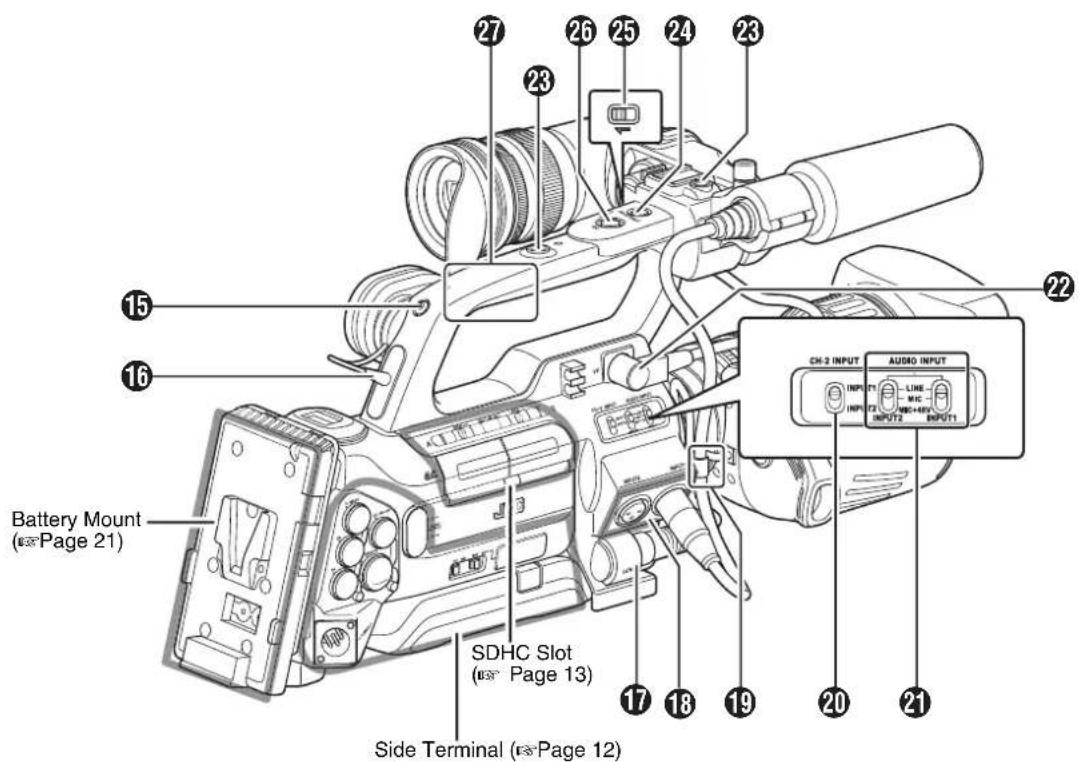
15 Back Tally Lamp (Page 30, 87)
16 [PHONES] Earphone Connector (3.5) (Page 45)
⑰[LENS] Lens Connector (12-pin Connector) (Page 19)
⑱ [INPUT1/INPUT2] Audio Input Terminal 1, 2 (XLR 3-pin(x2) (Page 44))
⑲ Microphone Cable Clamp (Page 19)
20[CH-2 INPUT] CH-2 Audio Input Terminal Selection Switch
Select the audio input terminal to record to CH-2.
(Page 44)
- Audio from [INPUT1] terminal is input to CH-1 regardless of the setting.
24[AUDIO INPUT 1/2] Audio Input Signal Selection Switch (Page 44)
22 Viewfinder Connector (20-pin) (Page 20)
②3Accessory Mounting Screw Hole (x2)
Memo:
24[FOCUS ASSIST] Focus Assist Button (Page 35)
25Record Button Lock Switch
Set the switch toward the lens to lock the [REC] trigger button 26.
Memo:
- The [REC] trigger button (Page 10) at the side control panel on the right of the camera recorder is not locked.
26[REC] REC Trigger Button (Recording Start/Stop) Starts/stops recording.
Memo:
- The [REC] trigger button (Page 10) at the side control panel on the right of the camera recorder is interlocked with this button.
27Handle
Names of Parts (continued)
Side Control Panel
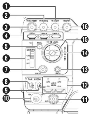
① [VF BRIGHT] Viewfinder Luminance Adjustment Knob (Page 28)
② [VF PEAKING] Contour Adjustment Knob (Page 28)
Memo:
- This knob does not function when Focus Assist is activated. (Page 35)
③[FOCUS ASSIST] Focus Assist Button
Press this button during shooting to display the focused area in either blue, red, or green. This enables easy and accurate focusing. (Page 35)
4 [USER1], [USER2], [USER3] User Buttons (Page 74)
Use these buttons to switch shooting conditions according to the object. The functions change as below according to the operation mode (Page 7).
![JVC GY-HM700U - [USER1], [USER2], [USER3] User Buttons (Page 74) - 1](/content/2026/06/1254269/images/f8a0120dfc24b9bc3f7eef7bb912eeb6b4f82543cee53cc2c85aca16b8e84ba2.jpg) |
Memo:
- Set the functions of the [USER1, USER2, USER3] buttons in the menu. (Page 74)
- When the menu screen is displayed, these buttons function as the menu operation buttons. (※ Page 66 [Operation Buttons])
⑤ [MENU] Menu Button (Page 66)
⑥ [ND FILTER] ND Filter Switch (Page 43)
⑦[STATUS] Status Screen Display Button
- Press the [STATUS] button to display the status screen on the viewfinder and LCD monitor during normal screen display (when the menu screen is not displayed). (Page 16 [Status Screen])
- Switches between [Main Menu] and [Favorites Menu] when the [STATUS] button is pressed while the menu screen is displayed. (Page 66)
⑧ [GAIN] Sensitivity Selection Switch (Page 37)
⑨[WHT.BAL] White Balance Selection Switch (Page 40)
You can select one of the three white balance types.
⑩[POWER] Power ON/OFF Switch
Turns ON/OFF the power. When the power is OFF, "POFF" appears on the LCD monitor and viewfinder.
Wait for 5 seconds or more to turn on the power again.
⑪[REC] REC Trigger Button (Recording Start/Stop)
Starts/stops recording.
The [REC] trigger button (Page 9) 26 on top and the [REC] trigger button (Page 14) of the lens are interlocked with this button.
Memo:
- When [1394 Rec Trigger] in the [Others] menu is set to "Split", this button becomes the recording start/stop button of the external equipment. (Page 88) (Page 116 [Backup Recording])
12[AUDIO LEVEL CH-1/CH-2]/[AUTO] CH-1/CH-2 Recording Level Adjustment Knob/Auto Indicator (Page 44)
⑬[CANCEL] Cancel Button
Cancels various settings and stops playback.
14 Cross-Shaped Button (▲▼◀▶)/Set Button (●)
The function changes according to the operation status of the camera recorder.
■ During menu operation (all modes) (Page 66)
Center Set button (●) : Confirms menu items and setting values Cross-shaped button (▲▼) : Selects menu items and setting values
■During Camera mode
Shutter operation:
Center Set button (●) : Shutter ON/OFF
Cross-shaped button (▲▼): Switches shutter speed when shutter is ON
AE level operation : Cross-shaped button (◀▶)
Memo:
- When [Camera Function]→[Switch Set]→[AE LEVEL] is set to "AE LEVEL/VFR", the cross-shaped button (◀▶) is used to set the number of frames during Variable Frame REC.
(Page 56 [Variable Frame REC])
( Page 75 [AE LEVEL])
■ During Media mode (SD Card mode) (r- Page 57)
Thumbnail operation : Cross-shaped button (▲▼◀▶), center Set button (●)
⑮Operation Mode Indicator
Lights up as below according to the operation mode. ( page 7)
| Operation Mode Color | |
| Camera Mode Blue/Purple | |
| Media Mode (SD Card Mode) Green | |
| Media Mode (IEEE1394 Mode) Orange | |
| USB Mode Orange |
Memo:
- You can select whether to light up the indicator using [Mode LED] in the [Others] menu. (Page 87)
16[MONITOR] Audio Monitor Level Adjustment Knob
For adjusting the volume of the monitor speaker and earphones.
Viewfinder

①Viewfinder Slide Lock Ring
For loosening the ring and adjusting the position of the viewfinder ⑤ to the left or right.
②Eyepiece Focus Ring
For adjusting the visibility.
③Viewfinder Eyepiece Lock Ring
For loosening the ring and adjusting the eyepiece position of the viewfinder to the front or back.
4 Viewfinder
⑤Eyepiece
Prevents external light from entering the viewfinder screen and cameraman's vision.
LCD Monitor

① LCD Monitor (Page 28)
②[LCD PEAKING +/-] LCD Contour Adjustment Button (u=Page 28)
③[LCD BRIGHT +/-] LCD Display Brightness Adjustment Button (Page 28)
4[AUDIO SELECT CH-1/CH-2] Audio Recording Mode Switch (v 2 Page 44)
⑤ [TC DISPLAY] TC/UB Display Switch (Page 46)
6 [TC GENE.] Time Code Generator Switch (15 Page 46)
⑦ LCD Cover Lock Release Knob (Page 28)
Names of Parts (continued)
Side Terminal

①[HD/SD-SDI] HD/SD-SDI Output Terminal (BNC) (Page 114)
②[Y/VIDEO] Y/Composite Video Signal Output Terminal (BNC) (Page 114)
③[PB] PB Video Signal Output Terminal (BNC) (Page 114)
4[PR] PR Video Signal Output Terminal (BNC) (Page 114)
⑤ [REMOTE] Remote Terminal (Page 119)
6 [DC INPUT] DC Input Terminal (Page 21)
Input terminal for DC 12 V power supply. Connects with an AC adapter.
⑦[AUDIO OUTPUT] Audio Output Terminal (RCA)
Output terminal for audio signals.
●Input audio signals are output during Camera mode.
●Playback audio signals are output during Media mode.
●Audio from input audio signals is output during HD/DV signal (IEEE1394) input.
Memo:
●Alarm tone is not output.
8 [HD/DV] IEEE1394 Terminal Mode Switch (Page 115)
9 [INT/EXT] IEEE1394 Interface Terminal Switch (Page 115)
For selecting a valid IEEE1394 interface terminal.
[EXT] : Enables IEEE1394 signals from the [IEEE1394] terminal ⑬.
[INT] : Enables the accessory connector ② at the rear of the camera recorder. (Page 13)
⑩Shoulder Pad Slide Button
For adjusting the shoulder pad position. Press this button to adjust the shoulder pad ⏻ position to the front or back.
⑪Shoulder Pad
⑫ [USB] USB Terminal (Page 118)
⑬ [IEEE1394] IEEE1394 Terminal (4-pin)
For connecting digital video equipment with IEEE1394 terminal using an IEEE1394 cable (sold separately). To enable this terminal, set the [INT/EXT] IEEE1394 terminal switch ⑨ to [EXT].
( Page 115 [IEEE1394 Connection])
( Page 117 [Stream Transmission to a Non-linear Editing System])
Note:
- When connecting IEEE1394 cables, check that the connectors are facing the right direction before you insert.
Memo:
- Put on the covers when the connectors are not in use.
SD Slot
Page 31

①Card Slot A Status Indicator
②[ SLOT SELECT] Card Slot Selection Button
For switching SDHC cards.
③SDHC Card Cover
④Card Slot B Status Indicator
⑤[OPEN] SDHC Card Cover Open/Close Knob
Rear

①Shoulder Belt Mount (x2)
For mounting a shoulder belt (sold separately).
Note:
- Be sure to use a shoulder belt with the strength to withstand the weight of this camera recorder.
- If the shoulder belt is not properly attached, the camera recorder may fall and cause injuries.
- Check the instruction manual provided with the shoulder belt before using.
②Accessory Connector (Connects to an optional accessory)
③ Battery Mounting Folder (Page 21)
The shape is different for GY-HM700CHU/GY-HM700U and GY-HM700CHE/GY-HM700E.
* The above is the illustration for GY-HM700CHE/GY-HM700E.
Names of Parts (continued)
Zoom Lens
(Supplied with GY-HM700U/GY-HM700E only)
CANON KT14 x 4.4KRSJ

① Focus Ring
②Zoom Lever/Ring
To operate zoom with this lever, turn the [ZOOM] switch 13 and set it to "MANU.".
③Iris Ring
To operate auto iris, set the iris mode switch ⑧ to "A".
4 Lens Cable
⑤[REC] Record Trigger Button
Starts/stops recording.
6[RET] Return Video Button
Press this button to play back and check the latest clip, according to the settings under [Clip Review] of [Switch Set] in the [Camera Function] menu. (Page 74)
(Page 52 [Viewing Recorded Videos Immediately (Clip Review)])
Memo:
- When [LENS RET] of [Switch Set] in the [Camera Function] menu is set to "Focus Assist", this button functions as the Focus Assist button. (Page 74)
⑦Zoom Servo Control Lever
To operate zoom servo with the zoom servo control lever, set the [ZOOM] switch ⑬ to "SERVO".
- Zooms into wide angle and increases the angle of view when "W" is pressed.
- Zooms into telephoto and decreases the angle of view when "T" is pressed.
- Zoom speed increases when the lever is pressed hard.
8 Iris Mode Switch
A : Auto iris operation mode.
M : Manual iris operation mode.
9 Iris Momentary Button
Press and hold this button to change to auto iris mode when the iris mode switch 8 is set at "M".
10[I.G.] Iris Speed Adjustment Knob
If the speed is set too fast, opening/closing of the iris becomes unstable and hunting may occur. Readjust the speed in this case.
⑪Filter Built-In Screw
A transparent or UV filter for lens protection can be installed inside the lens hood from the front. Filters for various effects can also be used.
●Installable filter types
When installed on the hood : 82mmP0.75
When installed on the lens body : 72mmP0.75
⑫Zoom Servo Connector
For connecting a zoom servo unit (sold separately).
⑬[ZOOM] Zoom Switch
SERVO : Enables zooming with the zoom servo control lever ⑦.
MANU. : Enables zooming with the zoom lever/ring ②.
14 Back Focus Ring/Lock Screw
Exclusive ring for adjusting the back focus. After adjusting, secure with a lock screw.
( Page 27 [Adjusting Back Focus])
⑮[M] Macro Focus Ring (for close-ups)
Turn the ring in the direction of the arrow to take close-up shots of small objects.
Normal focusing and zooming cannot be performed in macro mode.
To take macro shots
- Set focus ring ① to infinity (∞).
- Set zoom ring ② to the maximum wide angle.
- Rotate this ring in the direction of the arrow to adjust focus on the object.
Note:
●As the back focus knob is located nearby, be careful not to mistake the two knobs.
- Do not forget to restore the macro ring to its original position after use. (Page 27 [Adjusting Back Focus])
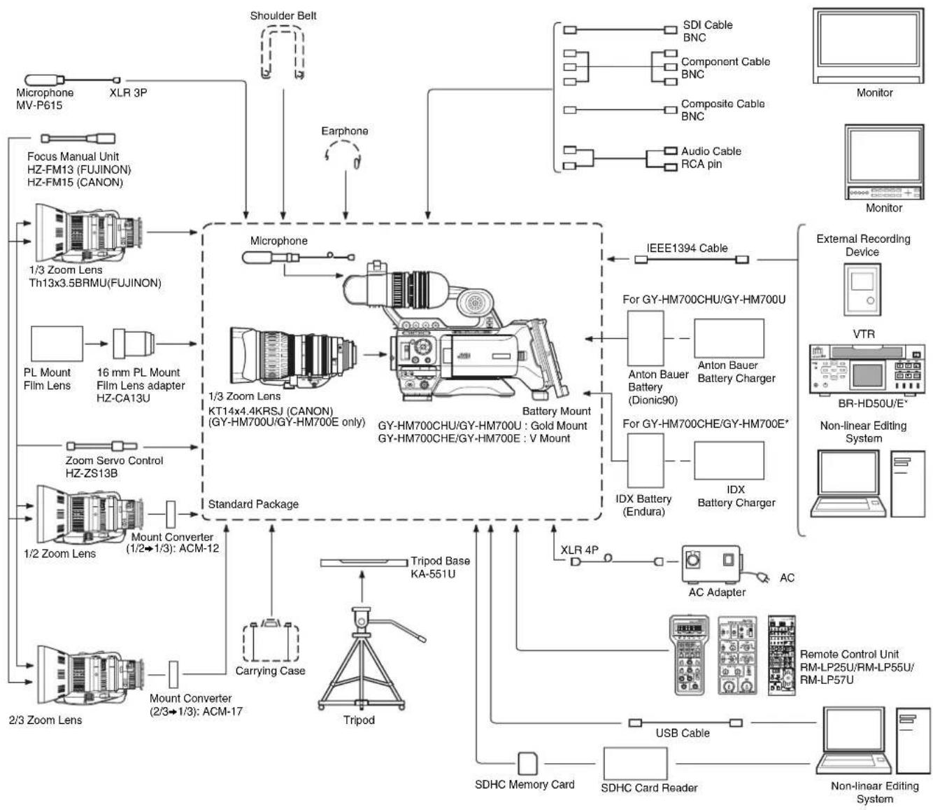
Basic System Diagram
flowchart
graph TD
    A["Microphone MV-P615"] --> B["Focus Manual Unit HZ-FM13 (FUJINON) HZ-FM15 (CANON)"]
    B --> C["1/3 Zoom Lens Th13x3.5BRMU(FUJINON)"]
    C --> D["1/3 Zoom Lens KT14x4.4KRSJ (CANON) (GY-HM700U/GY-HM700E only)"]
    D --> E["Standard Package"]
    E --> F["2/3 Zoom Lens"]
    F --> G["Mount Converter (1/2→1/3): ACM-12"]
    G --> H["Carrying Case"]
    H --> I["Tripod Base KA-551U"]
    I --> J["Tripod"]
    J --> K["Switch"]
    K --> L["SDHC Memory Card"]
    K --> M["SDHC Card Reader"]
    K --> N["Remote Control Unit RM-LP25U/RM-LP55U/RM-LP57U"]
    K --> O["USB Cable"]
    O --> P["AC Adapter"]
    P --> Q["XLR 4P"]
    Q --> R["For GY-HM700CHU/GY-HM700U"]
    R --> S["Anton Bauer Battery (Dionic90)"]
    S --> T["For GY-HM700CHE/GY-HM700E*"]
    T --> U["IDX Battery (Endura)"]
    U --> V["IDX Battery Charger"]
    V --> W["IEEE1394 Cable"]
    W --> X["External Recording Device"]
    X --> Y["VTR"]
    Y --> Z["BR-HD50U/E*"]
    Z --> AA["Non-linear Editing System"]
    AA --> AB["Monitor"]
    AB --> AC["Monitor"]
    AD["Shoulder Belt"] --> AE["Earphone"]
    AE --> AF["Microphone"]
    AF --> AG["Standard Package"]
    AG --> AH["Carrying Case"]
    AH --> AI["Tripod Base KA-551U"]
    AI --> AJ["Switch"]
    AJ --> AK["SDHC Memory Card"]
    AK --> AL["SDHC Card Reader"]
    AL --> AM["Remote Control Unit RM-LP25U/RM-LP55U/RM-LP57U"]
* Models with an E suffix are for the European market and will not employ the UL Listing mark.
Displays on the LCD Monitor and Viewfinder
You can display the camera status, media information, zebra pattern, and various markers in the video image on the LCD monitor and viewfinder screens during shooting.
Besides camera and playback images, the following characters are displayed on the LCD monitor and viewfinder.
■ Status screen (Page 16)
■ Auto White display* (Page 18)
■ Menu setting screen (Page 18)
■ Alarm display (Page 18)
■ Marker and safety zone indicators* (Page 104)
■ Zebra pattern display (Page 18)
* Displayed in Camera mode only
Memo:
- When [Analog Out Char.]/[SDI Out Char.] in the [A/V Out] menu is set to "On", the status screen and menu screen are also displayed in the video image of the video signal output terminal. (Page 86)
![Viewfinder [DISPLAY] Button [STATUS] Button LCD Monitor](/content/2026/06/1254269/images/4ca2cdd2549f58c3249278ba03f664238a1bcad17725aec6030fce2bb19016e9.jpg)
Status Screen
This screen allows you to check the current settings.
To display the status screen, press the [STATUS] button in the normal screen.
The status display differs according to the operation mode(4 types). (Page 7 [Operation Mode])
■Status Screen in Camera Mode (Page 94)
Viewfinder display
The display switches between the 5 screen types with every press of the [STATUS] button. (STATUS 0→1→2→3→4→0)
LCD monitor display
The display switches between the 5 screen types with every press of the [STATUS] button. (STATUS 0→1→2→3→4→0) Press the [DISPLAY] button to switch to the enlarged status display screen. (Page 17)

flowchart
graph TD
    A["30/24 fps"] --> B["STATUS 0 Screen"]
    B --> C["1280x720 30/24 fps 24p HQ"]
    C --> D["STATUS 1 Screen"]
    D --> E["CAMERA INFORMATION"]
    E --> F["STATUS 2 Screen"]
    F --> G["SWITCH ASSIGN"]
    G --> H["STATUS 3 Screen"]
    H --> I["30/24 fps"]
    I --> J["STATUS 4 Screen"]

    subgraph Status 0 Screen
        C
        D
        E
        F
        G
        H
    end

    subgraph STATUS 1 Screen
        C
        E
        F
        G
        H
    end

    subgraph STATUS 2 Screen
        E
        G
        H
    end

    subgraph STATUS 3 Screen
        I
    end

    note1["Press [DISPLAY"]]
    note2["Press [DISPLAY"]]

    C -->|MAX 123% MIN 45% S.DTL B-3 A<3200K> STBY ▲F5.6 AE+1 9dB 1/10000
    ZEBRA1 ZEBRA2 AUDIO FORMAT MEDIA
        CH1M CH2M QuickTime A125min B123min STBY ▲282min Jan 2. 2009 01:23:45AM
    FAW GAIN L/M/H USER 1 USER 2 USER 3 RET SKIN/SPOT AELEVEL STBY ▲282min Jan 2. 2009 01:23:45AM
        NONE 0dB/9dB/12dB BARS B.STRETCH3 LOAD FILE CLIP REVIEW SPOT METER AE LEVEL/VFR
        MAX 123% MIN 45% S.DTL B-3 A<3200K> STBY ▲100 min 24p HQ STBY ▲100 min 282min
    CH1 CH2
    DF FREE
    STBY ▲A100 min 1280 x 720 B 100 min
STATUS 1 Enlarged Display Screen (LCD monitor only)
■Status Screen (VF/LCD) During Clip Playback in Media Mode (SD Card Mode) (Page 100)
The display switches between the 3 screen types with every press of the [STATUS] button. (STATUS 0→1→2→0)

STATUS 2 Screen
■ Status Screen in Media Mode (IEEE1394 Mode) (Page 102)
The display switches between the 2 screen types with every press of the [STATUS] button. (STATUS 0→1→0)

STATUS 1 Screen
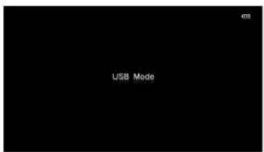
■Status Screen in USB Mode
This screen displays the USB mode.
Enlarged Status Display on LCD Monitor
You can enlarge and display only the characters of the status screen on the LCD monitor. (Camera mode only)
![CH1 48k CH2 -∞ 40 30 20 10 0 dB OVER OVER DF FREE TC12H34M34S12F STBY A100 min 1280 x 720 ●II 24p HQ B 100 min 282min [BISPLAY] Button](/content/2026/06/1254269/images/3aa157686231a965d1b7e2f76db7e7131b4e131d12a05a5177711aca9f28c391.jpg)
1 Set [LCD + VF] in the [LCD/VF] menu to "On". (C5 Page 82).
2 Press the [DISPLAY] button while the LCD screen is displayed.
The display switches between the same display as the viewfinder and the enlarged display with every press of the button.
Memo:
●During enlarged display of the status on the LCD monitor screen, the video image remains displayed on the viewfinder.
Displays on the LCD Monitor and Viewfinder (continued)
Auto White Display (Camera Mode Only)
Displays the operation and result when Auto White Balance is activated.
Page 40 [Adjusting the White Balance])
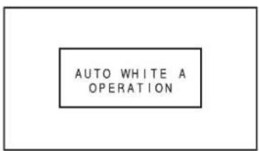
Menu Setting Screen
For configuring various settings.
Press the [MENU] button to display the menu setting screen.
( Page 66 [Basic Operations in Menu Screen])

[Main Menu] Screen
Alarm Display
- Alarm is displayed during the status screen display in Camera mode (STATUS 0, 1, 4) and Media mode. If the alarm sounds during STATUS 2 or 3 Screen display in Camera mode, the display will return to STATUS 0 Screen and alarm will be displayed. (Page 122 [Error Displays and Actions])
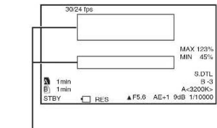
Alarm Display Area
Zebra Pattern Display
Two types of zebra patterns that indicate the luminance level of the video image can be displayed on this camera recorder. You can set the luminance levels for displaying the two types of zebra patterns.
( Page 50 [Setting Zebra Pattern])

Memo:
- Use the [ZEBRA ON/OFF] switch in front to turn ON/OFF the zebra pattern display.
- Set the display pattern and luminance level in [LCD/VF]→[Shooting Assist]→[Zebra]. (Page 83)
Attaching Accessories
Attaching the Zoom Lens
(Supplied with GY-HM700U/GY-HM700E only)
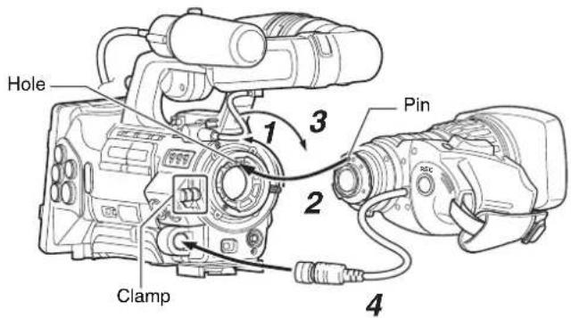
1 Loosen the mount ring.
2 Attach the zoom lens such that the pin matches the hole of the mounting area.
3 Tighten the mount ring.
4 Connect the cable connector.
5 Attach the lens cable to the clamp.
Memo:
●Tighten the mount ring completely. If it is not fully tightened, the lens may drop or the back focus may be out of alignment.
- When attaching or removing the zoom lens, set the [POWER] switch of the camera recorder to "OFF".
Attaching the Microphone (Supplied)
You can attach the supplied microphone to the microphone holder.
The supplied microphone has a phantom power supply.
1 Turn the knob on the microphone holder anticlockwise to loosen and open the microphone holder.
2 Place the microphone in the microphone holder.
3 Turn the knob on the microphone holder clockwise to secure the microphone.
4 Connect the microphone cable to the [INPUT1] or [INPUT2] terminal.
5 Pin the microphone cable to the clamp.
6 Make sure to perform the correct settings for the phantom microphone (Page 44).
![Knob Microphone Microphone Holder Clamp [INPUT1/INPUT2] Terminal](/content/2026/06/1254269/images/0edfdee2ee8a39bc19c716dafcc41bba5046d744c7e20c9241e1f02189dfa52f.jpg)
Attaching Accessories (continued)
Attaching the Viewfinder (Supplied)
1 Slide the viewfinder in the direction of the arrow to attach it.
2 Turn the slide lock ring to secure the position of the viewfinder.

3 Attach the viewfinder cable to the viewfinder terminal.
4 Pin the viewfinder cable to the clamp.
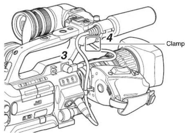
Power Supply
To use this camera recorder, you can attach a battery pack or connect an AC adapter to it.
( Page 21 [Using a Battery Pack])
( Page 21 [Using AC Power (DC IN Power)])
Note:
- Set the [POWER] switch to "OFF" before changing the power supply that operates this camera recorder.
Using AC Power (DC IN Power)
Use an AC adapter (sold separately) to operate the camera recorder with AC power.
1 Connect the DC cable of the AC adapter to the [DC INPUT] terminal of the camera recorder.
Check that the power of the camera recorder and the AC adapter is turned "OFF" and connect as shown in the diagram.
![[DC INPUT] DC Cable DC OUTPUT AC Adapter](/content/2026/06/1254269/images/707b27ad8d65ff9e6b19b4802d674bc190912c2c90c6affea5bc43db2704199a.jpg)
2 Set the [POWER] switch of the camera recorder to "ON" after turning on the AC adapter.
Power will be supplied to the camera recorder.
Note:
- Do not insert or remove the DC cable during recording.
- Do not use power supply of high voltage fluctuation, containing noise such as ripple, or with insufficient capacity.
■Charging the Built-In Battery
The date/time and time code data are stored in the built-in rechargeable battery. When power is connected to the camera recorder, the built-in battery always gets charged. When the power is disconnected, the battery gradually discharges. The battery will be totally discharged if left unused for 3 months and the date/time and time code data will be reset. When this happens, set the [POWER] switch to "ON" to display the [Initial Setting] screen, then set the date/time. (Page 25 [Setting the Clock (Initial Setting)])
Using a Battery Pack
Recommended Batteries
U model : Dionic90 (Anton Bauer)
E model : Endura-7 (IDX)
* Models with an E suffix are for the European market and will not employ the UL Listing mark.
Note:
●Make use of the recommended batteries. Heavy batteries may fall off if not used correctly.
- See the battery instruction manual on how to charge the battery.
Battery Operating Time
The following are the approximate times for continuous operation on fully-charged batteries.
| Battery | Continuous Operating Time (At 25 °C) |
| Dionic90 (U model) Approx. | 3.2 h |
| Endura-7 (E model) Approx. | 2.5 h |
Memo:
●Actual operating times may differ depending on the age of the battery, charging condition, and operating environment.
- Operating time is shortened in cold environment.
- Operating time is shortened when the electronic zoom lens and LCD screen are frequently used.
Precautions for the Battery Operation
- Do not remove the battery when the [POWER] switch is "ON".
- Do not insert or remove the DC cable when the battery is in use.
- Leaving the camera recorder unused with the battery inside will deplete the battery power even if you set the [POWER] switch to "OFF". Remove the battery if you are not using the camera recorder.
Using a Battery Pack (continued)
Attaching the Battery (GY-HM700CHU/GY-HM700U)
Use the Dionic90 (Anton Bauer) battery.
1 Align the battery guide pins (x3) with the battery, adapter, and guide hole and insert straight.

Memo:
- If the guide pins are not inserted straight, the battery will not be attached correctly.
2 Slide the battery toward the SDHC card cover side panel until it snaps into place.
■Detaching the Battery
Press down the release lever and slide the battery toward you to detach it from the camera recorder.

Attaching the Battery (GY-HM700CHE/GY-HM700E)
Use the Endura-7 (IDX) battery.
1 Attach the battery.
Face the terminal downward and attach the V mount of the battery onto the V mount attachment bracket of the camera recorder.

2 Press down the battery until it snaps into place.
■Detaching the Battery
Press down the release lever and slide the battery upward to detach it from the camera recorder.

Power Status Display
■Viewfinder and LCD Monitor Screens
The power status is displayed on the status and menu screens. If the battery or supplied voltage from the AC adapter is low, a warning will be displayed in red.
Note:
- If the battery in use is not a recommended one, the battery mark which indicates the battery level may not appear.
■Status screen
Page 94 [Status Screen in Camera Mode])
Page 100 [Status Screen in SD Card Mode])
( Page 102 [Status Screen in IEEE1394 Input Mode])

■Enlarged status display on the LCD monitor (Page 103)
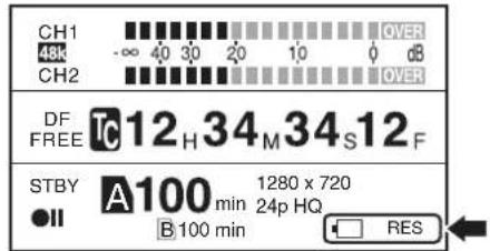
■ Menu screen (Page 66)

■Warnings by Lamps and Alarm Tones
●Warning status is indicated by tally lamps and alarm tones.
●The front and back tally lamps of the camera recorder blink.
●Alarm tone is output from the monitor speaker or [PHONES] terminal.
Memo:
- If you continue to use the camera recorder while the power warning is displayed, the camera recorder will stop automatically when the battery or supplied voltage from the AC adapter becomes lower.
●Alarm tone is not output during recording.
Note:
- The remaining battery power and time are displayed as there are from the battery information. Accurate data may not be displayed according to the battery condition. Replace the battery as soon as possible when the remaining battery power and time are low.
Precautions for Batteries
●Store the battery in a cool and dry place when not in use. Do not expose the battery to high temperatures (such as in a car under direct sunlight). This will cause battery leakage and shorten the battery life.
- Operating time is shortened if the battery terminal is dirty.
- If the operating time shortens drastically even after charging, the battery may be reaching the end of its life. Replace the battery with a new one.
Charging
- Use up the charge completely before you charge the battery. If the battery is not fully discharged before charging, the battery capacity may drop after repeated cycles.
- If the battery capacity drops due to repetitive shallow charging and discharging, it may be recovered by using up the charge completely and then fully charging the battery again.
- If you charge the battery immediately after using while the battery is still warm, it may not be fully charged.
- It is recommended to charge the battery in an environment between 10 °C and 35 °C. The battery may not be fully charged or the charging time may be prolonged if charged under low temperatures (below 10 °C).
Turning On/Off the Power
Turning On the Power
1 Set the [POWER] switch to "ON".
The camera recorder starts up in Camera mode.
Memo:
- The camera recorder always start up in Camera mode when the [POWER] switch is set to "ON".
- Press the [CAM/MEDIA] button to switch to a different mode. The operation mode indicator changes as below. See [Operation Mode] (Page 7) for details of each operation mode.
●During Camera mode : Lights up in blue/purple
●During Media mode (SD Card mode) : Lights in green
- During Media mode (IEEE1394 Input mode) : Lights up in orange
●During USB mode : Lights up in orange
●During mode switching : Blinks in the color of the new mode
Note:
- The camera recorder will switch to IEEE1394 Input Mode only when the IEEE1394-connected equipment is in operation.
![CH-1 BOTH CH-2 ON OFF MONITOR SELECT DISPLAY CAM/MEDIA FULL AUTO [CAM/MEDIA] Button [MENU] Button Cross-Shaped Button (▲▼▲), Set button (●) [CANCEL] Button JNC [REC] Button [POWER] Switch](/content/2026/06/1254269/images/4c68183e9767bf05b50044ed4aecdab9d3bdf6b85aed3133333d9c7947379cf4.jpg)
■Camera mode
Camera images are output on the viewfinder and LCD monitor. When a recordable SDHC card is inserted, the camera recorder enters the recording standby mode.
"STBY" appears on the operation mode display area of the LCD monitor and viewfinder.
Press the [REC] trigger button to start recording.
Memo:
-Playback of SDHC card is not possible in Camera mode. However, you can use the Clip Review function to check the most recently recorded video clip. (Page 52)
■Media mode (SD Card mode)
This mode allows you to play back or delete clips recorded on the SDHC card.
When a playable SDHC card is inserted, the thumbnail or playback screen is output on the viewfinder and LCD monitor.
■ Media mode (IEEE1394 Input mode)
This mode allows you to check IEEE1394 input signals. When playable IEEE1394 signals are input, input images are output on the viewfinder and LCD monitor. IEEE1394 input signals cannot be recorded.
Turning Off the Power
Set the camera recorder to the recording standby or stop mode.
1 Set the [POWER] switch to "OFF".
2 Remove the battery and the power to the [DC INPUT] terminal (when not in use for a long time).
Note:
- Do not set the [POWER] switch to "OFF" during recording. Check that the operation mode display is "STBY" or "STOP" before you turn off the power.
- If you have mistakenly set the [POWER] switch to "OFF" during recording, wait for 5 seconds or more before you turn on the power again.
- When turning off the power, first set the [POWER] switch of the camera recorder to "OFF". Do not remove the battery or turn off the AC power while the [POWER] switch is set to "ON".
Setting the Clock (Initial Setting)
Set the date/time of the built-in clock in the [Initial Setting] screen. The configured date/time data is saved in the built-in rechargeable battery even if the power is turned off.
Setting the Clock in the [Initial Setting] Screen
The [Initial Setting] screen appears when the power is turned on for the first time and when the built-in battery is turned on again after being fully discharged.
All operations are disabled until initial settings are complete.
![[MENU] Button Cross-Shaped Button (▲▼▲▼), Set button (●) [POWER] Switch](/content/2026/06/1254269/images/eb6378089dcf3b9463d5dd225688d907496649aa824a384cbb86d2812f02bc99.jpg)
1 Set the [POWER] switch to "ON".
The [Initial Setting] screen appears.
■For GY-HM700CHU/GY-HM700U

For GY-HM700CHE/GY-HM700E

2 Specify [Time Zone] and [Date/Time].
① Move the cursor with the cross-shaped button (◀▶) and select the setting item.
② Change the values with the cross-shaped button (▲▼).
3 Press the Set button (●) after setting is complete.
The clock is set to 0 seconds of the input date/time.
Memo:
- The configured date/time data can be displayed on the LCD monitor and viewfinder and be recorded to the SDHC card.
- The value of the year can be set in the range of "2000" to "2099".
Changing the Time after Initial Setting
■ Setting the date/time (Page 88)
1 Select [Others]→[Date/Time].
The [Date/Time] setting screen appears.

2 Set the date and time.
① Move the cursor with the cross-shaped button (◀▶) and select the setting item.
② Change the values with the cross-shaped button (▲▼).
3 Press the Set button (●) after setting is complete.
The clock is set to 0 seconds of the input date/time.
Setting the Clock (Initial Setting) (continued)
Changing the Display Style
You can change the display style of the date/time on the menu.
Memo:
- To perform the settings while looking at the monitor screen connected to the video signal output terminal, set [Analog Out Char.] or [SDI Out Char.] in the [A/V Out] menu to "On". (Page 86)
■ Setting the date style (Date Style) (Page 85)
① Select [LCD/VF]→[Status Display]→[Date/Time].
②Select the date display style.
[Setting values:YMD (year, month, day), MDY (month, day, year), DMY (day, month, year)]
③ Press the Set button (●).
■ Setting the time style (Time Style) (Page 85)
① Select [LCD/VF]→[Status Display]→[Time Style].
②Select the time display style.
[Setting values:12hour (12 hour display), 24hour (24 hour display)]
③ Press the Set button (●).
Date/Time Display in Different Operation Modes
| During Camera Mode Date/time of the built-in clock is displayed. | |
| During Media Mode (SD Card Mode) | Shooting date/time of the clip being played back is displayed. |
| During Media Mode (IEEE1394 Mode) | Date/time is not displayed. |
Adjusting the Monitor Speaker
The monitor speaker can be rotated 180 degrees. Adjust according to the position of your ear.
![180 Degrees Rotation Monitor Speaker [MONITOR] Level Adjustment Knob](/content/2026/06/1254269/images/73948e94040beb4940f6573704f6e58b0a45802801226094f166b80018432122.jpg)
Memo:
- Adjust the volume of the monitor speaker with the [MONITOR] level adjustment knob at the side control panel on the right of the camera recorder. Various warning alarm tones may also be output repeatedly. (158 Page 123)
Note:
- The rotation angle of the monitor speaker is 180 degrees. Do not over-rotate the monitor speaker.
Adjusting Back Focus
When the lens is first attached, adjust the back focus of the lens if the focus is not clear when zoomed to the telephoto or wide angle end.
- Place an object 3 m and above away from the camera.
●The Siemens Star Chart is most suitable as the object.


natural_image
Circular black-and-white radial pattern with no text or symbolsSiemens Star Chart
1 Set the iris mode switch of the lens to "M" (manual).
2 Set the zoom mode switch to "MANU." (manual).
3 Turn to open the iris ring.
Adjust the lighting such that the optimum image level can be obtained.
4 Turn the zoom lever to set the lens to the maximum telephoto position.
5 Turn the focus ring to adjust the focus of the object.
6 Set the lens to the maximum wide angle position.
7 Loosen the lock screw of the back focus ring.
8 Shoot the same object and secure the back focus ring at the position where the object is in focus.
9 Repeat steps 4 to 8 three times until the object is in focus at both the telephoto and wide angle positions.
10 Tighten and secure the lock screw of the back focus ring.
Adjusting the LCD Monitor and Viewfinder
Adjusting the LCD Monitor
You can change the angle and brightness of the LCD monitor screen according to your usage condition.
Changing the brightness of the screen will not affect the recorded images.
![[LCD BRIGHT +/-] Button LCD Lock Release Knob 1 2 Tilt 180 degrees upward Tilt 90 degrees downward [LCD PEAKING +/-] Button](/content/2026/06/1254269/images/4dc3bf9386814cb9e969f565bd9739c520bf8b53bc6127945c5f4fa48e578a5d.jpg)
■Adjusting the Angle of the LCD Monitor
1 Slide the LCD lock release knob to open the LCD monitor.
2 Rotate the LCD monitor to adjust the angle.
●While the LCD monitor is open, you can rotate it 180 degrees upward or 90 degrees downward.
- Rotating the LCD monitor 180 degrees upward enables you to see the screen from the lens side. Select [Main Menu]→[LCD/VF]→ Set [LCD Mirror Mode] to "Mirror"→ Set button (●) (Page 82)
■Adjusting the LCD Monitor Screen
Adjusting contour and brightness
- Use the [LCD BRIGHT +/-] button to adjust the brightness of the LCD monitor screen. Press the [+] and [-] buttons simultaneously to return to standard settings.
[+] : Press this button to brighten the screen. [-] : Press this button to darken the screen.
●During adjustment, the brightness level is displayed on the LCD monitor screen.
●During Camera mode, SD Card mode (playback), or IEEE1394 mode

●During SD Card mode (thumbnail), menu operation, or USB mode

- Use the [LCD PEAKING +/-] button to adjust the contour of the LCD monitor screen. Press the [+] and [-] buttons simultaneously to return to standard settings.
[+] : Press the button to increase contour correction. [-] : Press the button to decrease contour correction. - During adjustment, the contour level is displayed on the LCD monitor screen. ( Page 28 [Adjusting contour and brightness] )
●During Camera mode, SD Card mode (playback), or IEEE1394 mode

●During SD Card mode (thumbnail), menu operation, or USB mode

Adjusting the Viewfinder
You can change the brightness and peaking of the viewfinder screen according to your usage conditions.
Changing the brightness of the screen will not affect the recorded images.
![[VF PEAKING] Knob [VF BRIGHT] Knob FOCUS GROUP VT REACH VT BRIGHT MOUNTOR Slide Lock Ring Eyepiece Focus Ring Eyepiece Eyepiece Lock Ring JME](/content/2026/06/1254269/images/1f49f893fb92df47f45af054aee31b372d99db548ad7c28875a581296c3d551b.jpg)
Note:
●A high-definition viewfinder is used on this camera recorder in order to provide an accurate focusing environment. Due to the characteristic of the display device, colors may appear on the images when you blink your eyes. This is not a malfunction. It does not affect the recorded images, SDI output, or component output.
■Adjusting the Angle
Adjust the position and angle of the viewfinder.
■Adjusting the Visibility
Turn the eyepiece focus ring to sharpen the image on the viewfinder screen.
■Adjusting the Viewfinder Screen
Adjusting contour and brightness
- Use the [VF BRIGHT] knob to adjust the brightness of the viewfinder screen.
- Use the [VF PEAKING] knob to adjust the contour of the viewfinder screen.
*Screen display during adjustment (r) Page 28 [Adjusting contour and brightness])
Displaying in black and white (Page 82)
You can display the viewfinder screen in black and white. Select [Main Menu] → [LCD/VF] → [VF Display] → Set button (●) → Select "B" → Set button (●)
Displays on the LCD Monitor and Viewfinder Screens
![CH-1 BOTH CH-2 ON OFF MONITOR SELECT DISPLAY CAM/MEDIA FULL AUTO [DISPLAY] Button Normal LCD Inversed LCD LCD opened at 40 degrees and above LCD closed at 40 degrees and below](/content/2026/06/1254269/images/81faa6f43f09949c9376982801265c0d120c1d373afdc2bdfee259de645852a6.jpg)
■When [LCD + VF] in the [LCD/VF] menu is set to "Off" (Page 82)
Displays on the LCD monitor and viewfinder screens (VF) are indicated as below.
| LCD Monitor Status LCD | Display VF Display | ||
| Closed LCD | Normal LCD OFF | ON | |
| Inversed LCD | ON OFF | ||
| Opened LCD | Normal LCD | ON OFF | |
| Inversed LCD | ON OFF | ||
Memo:
- Press and hold the [DISPLAY] button for 2 seconds to switch the display between the LCD monitor and viewfinder screens.
●The function to switch between LCD monitor and viewfinder displays by pressing the [DISPLAY] button can be canceled by opening/closing or rotating the LCD monitor. - When the LCD monitor is stored in the camera recorder in the direction of normal display, pressing of the [DISPLAY] button will not work.
- You can display both the LCD monitor and viewfinder screens at the same time by selecting [LCD + VF] in the [LCD/VF] menu. (Page 82)
■When [LCD + VF] in the [LCD/VF] menu is set to "On" (Page 82)
Displays on the LCD monitor and viewfinder screens (VF) are indicated as below.
| LCD Monitor Status | LCD Display | VF Display | |
| Closed LCD | Normal LCD | OFF | ON |
| Inversed LCD | ON | ON | |
| Opened LCD | Normal LCD | ON | ON |
| Inversed LCD | ON | ON | |
Memo:
- Press and hold the [DISPLAY] button for 2 seconds to turn ON/OFF the LCD monitor screen.
●The function to turn ON/OFF the LCD monitor screen by pressing the [DISPLAY] button can be canceled by opening/closing or rotating the LCD monitor.
●The viewfinder screen is always displayed.
Tally Lamps
These are indicator lamps for recording and warning. The operation changes according to the menu settings. When the battery or remaining space on the SDHC card is low, the lamps blink. (Camera mode only)
* Set using [Tally System]/[Front Tally]/[Back Tally] in the [Main Menu]→[Others] menu. (Page 87)

natural_image
Line drawing of a professional video camera with lens and external frame (no text or symbols)
| Menu Setting | [Tally System] | — | [Int] | [Ext] | [Studio] | |||
| [Front Tally]/[Back Tally] *1 | Off | On | Blink | On | Blink | On | Blink | |
| Camera Recorder Information | Warning | — | — | ▲ | — | ▲ | — | ▲ |
| Alarm | — | — | ■ | — | ■*2 | — | — | |
| External Device Information | Warning | — | — | — | — | ▲ | — | — |
| Alarm | ||||||||
| Camera Recorder Recording Status | Recording | — | ● | ● | — | — | — | — |
| Special Recording *3 | — | ● | ● | — | — | — | — | |
| External Device Recording Status | Recording | — | — | — | ● | ● | — | — |
| Remote Control Input | [CALL] | — | — | — | — | — | ■ | ■ |
| [TALLY(PGM)] | — | — | — | — | — | ● | ● | |
| [TALLY(PVW)] | — | — | — | — | — | ○ | ||
● :Lights up
▲: Blinks 4 times in 1 second
■: Blinks once in 1 second
: Only back tally lamp lights up
*1 : [Front Tally] and [Back Tally] can be set independently with the menu settings. (Page 87)
*2 : Only battery alarm is displayed.
*3 : Paused state during special recording ([Clip Continuous]). (Page 55)
Memo:
- Blinking takes priority over lighting up. However, [CALL] has priority in [Studio].
SDHC Cards
This camera recorder saves the recorded images and audio sound on the SDHC card (sold separately) in the card slot.
Memo:
- If the SDHC card contains files recorded by devices other than this camera recorder or files that are saved from a PC, the recordable time may be shorter or data may not be properly recorded.
■SDHC Cards to Use
Use a Class 6 SDHC card (4 GB - 32 GB).
Note:
- Using cards other than those from Panasonic, TOSHIBA or SanDisk may result in recording failure or data loss.
![SDHC Card Cover Knob Slot B Status Indicator Slot A Status Indicator [SLOT SELECT] Button A B CX-1 INPUT SDHC Card Cover](/content/2026/06/1254269/images/8801e4f3d99903450f305191042f26549f0accb3d4d95c03899cf80cf2ab6b21.jpg)
Inserting an SDHC Card
This camera recorder comes with two card slots for video/audio recording and playback (Slot A and B).
1 Slide the SDHC card cover knob of the desired slot in the direction of the arrow and open the cover.
2 Insert an SDHC card with the notched corner first.
3 Close the SDHC card cover.

■Card Slot Status Indicator
The following table shows the respective states of slot A and B.
| Lamp Slot Status | |
| Lights up in red Inserted SDHC card is being accessed.(writing/reading data)Do not turn off the power of the camera recorder or remove the SDHC card. | |
| Lights up in green On standby. Inserted SDHC card can be used for recording or playback. | |
| Light goes out ●SDHC card is not inserted.An unusable card is inserted.An SDHC card is inserted but a different slot is selected. |
Removing the SDHC Card
1 Check that the SDHC card to be removed is not being accessed (lights up in red).
2 Slide the SDHC card cover knob in the direction of the arrow and open the cover.
3 Push the SDHC card and remove it from the slot.
4 Close the SDHC card cover.

Memo:
- When both slots are inserted with usable SDHC cards, the previously selected slot is used.
Note:
●Data may be lost if you turn off the power of the camera recorder or remove the SDHC card when it is being accessed. All data recorded on the card, including the file that is being accessed, may be corrupted. Be sure to check whether the status indicator is lighted in green or not before you turn off the power or remove the SDHC card.
- If you mistakenly remove the card when it is being accessed, reinsert the card only after the status indicator goes off.
- The SDHC card may not be recognized if you insert and remove the card within a short time. When this happens, remove the card and wait for a few seconds before you reinsert.
SDHC Cards (continued)
Switching SDHC cards
When both card slots are inserted with SDHC cards, you can use the [SLOT SELECT] button to switch the card to use. When the memory on an SDHC card is full during recording, data recording automatically switches to the other card.
![[SLOT SELECT] Button Cross-Shaped Button (▲▼▲) Set button (●) [CANCEL] Button](/content/2026/06/1254269/images/6c40780543ae278f0baacb3c6b074508b4ddcade210fff79aebad354a9955647.jpg)
Note:
●The [SLOT SELECT] button is disabled during recording or playback. Cards will not be switched even if you press the button.
Formatting (Initializing) SDHC Cards
When the following cards are inserted, "Formatting Required" appears. Format the card using the camera recorder menu.
●Unformatted SDHC cards
- SDHC cards formatted under different specifications
* For details of the menu operation, see [Basic Operations in Menu Screen] (Page 66).
Note:
- Be sure to format the SDHC card on this camera recorder. SDHC cards formatted on a PC and other peripheral equipment cannot be used on this camera recorder.
Memo:
- To cancel the message display, press the [CANCEL] button. A [!] mark appears at the remaining media display area when an SDHC card that requires formatting is inserted.
1 Select [Format Media] in the [Media] menu. (Page 89)
2 Select the slot of the SDHC card to be formatted and press the Set button (●).

3 The status of the selected SDHC card appears.
4 Select [Format] and press the Set button (●).

5 Formatting starts.

6 Formatting is complete.
"Complete" appears when formatting is complete.
Memo:
- If you do not want to format the card, select [Cancel] or press the [CANCEL] button to return to the previous screen.
- If you remove the SDHC card during formatting, "Format Error!" appears and the camera recorder returns to the previous screen.
●During formatting, menu operation is unavailable but you can start recording. However, this is only available when a recordable SDHC card is inserted in the other slot. - Formatting cannot be performed in the following cases.
●Recording is in progress on the SDHC card to be formatted. - SDHC card is not inserted.
- Write-protect switch of the SDHC card is set ( displayed).
Note:
- If you format the SDHC card, all data recorded on the card, including video data and setup files, will be deleted.
Restoring the SDHC Card
It is necessary to restore the SDHC card if an abnormality occurs to the data in the card due to some reasons. The message “Restore Media” appears on the LCD monitor/viewfinder screen when an SDHC card that requires restoring is inserted.
Memo:
- To cancel the message display, press the [CANCEL] button. A [!] mark appears at the remaining media display area when an SDHC card that requires formatting is inserted.
1 Select [Restore Media] in the [Media] menu. (Page 89)
2 Select the slot of the SDHC card to be restored and press the Set button (●).
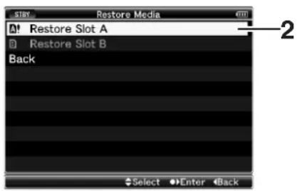
3 Restoring starts.

4 Restoring is complete.
- When restoring is complete, "Complete" appears and the camera recorder returns to the [Restore Media] screen.
- When no media that requires restoring is inserted, the camera recorder returns to the [Media] menu screen.

Note:
- [Restore Media] can only be selected in Camera mode. However, it cannot be selected while the camera recorder is recording. Select [Restore Media] in Camera mode when the camera recorder is not recording.
- [Restore Media] does not restore the SDHC card to its original states completely. If restoring fails, replace or format the SDHC card. Take note that formatting the SDHC card erases all information inside.
Memo:
●Restoring cannot be performed in the following cases.
●Camera recorder is recording in progress.
- SDHC card is not inserted.
- Write-protect switch of the SDHC card is set ( displayed).
●Restoring is not required.
Write-Protect Switch on the SDHC Card
①Slide the write-protect switch upward to enable writing or deleting.
②Slide the write-protect switch downward to prevent writing or deleting. (Images in the card are protected.)

flowchart
graph TD
    A["①"] --> B["Write/Delete Enabled"]
    C["②"] --> D["Write/Protect Switch"]
    B --> E["Write/Delete Disabled"]
    D --> F["Write/Protect Switch"]
Estimated Recordable Time of SDHC Cards
The estimated recordable time is only a guide. Differences may occur depending on the SDHC card in use and the battery condition.
( Page 71 [Camera Resolution])
(Page 71 [Frame & Bit Rate])
| QuickTime/MP4 SDHC Card Size | |||||
| Camera Resolution | Bit Rate | 4 GB | 8 GB | 16 GB | 32 GB |
| 1280x7201440x10801920x1080 | HQ 12 min | 25 min 50 | min 100 min | ||
| 1440x1080 $P 17 min 35 | min 70 min | min 140 min | |||
| 1280x720 | SP 22 min | 45 min 90 | min 180 min | ||
Memo:
- If the SDHC card contains files recorded by devices other than this camera recorder or files that are saved from a PC, the recordable time may be shorter or data may not be properly recorded.
Basic Shooting Procedures
![Front Tally Lamp 1 [REC] Button Back Tally Lamp 3 2 5 4 [POWER] Switch [REC] Button](/content/2026/06/1254269/images/5902e1df40a617bdc43f673e5fdf54573f29f1a7f86969a15851ff469756ea31.jpg)
Preparations
1 Attach the accessories. ( page 19)
2 Supply battery or AC adapter power to the camera recorder. (Page 21)
3 Insert an SDHC card. (Page 31)
4 Turn on the power of the camera recorder.
Set the [POWER] switch to "ON". The camera recorder starts up in Camera mode and is ready for shooting.
5 Adjust the angle of the LCD monitor and viewfinder. (Page 28)
Shooting
1 Configure the video and audio input settings.
You have to configure video settings such as brightness adjustment (iris, gain, shutter) and white balance adjustment in order to start shooting. You also have to adjust the audio input settings and audio recording level for audio recording.
- Adjusting the Iris (Page 37)
- Setting Gain (Page 37)
- Setting the Electronic Shutter (Page 38)
- Adjusting the White Balance (Page 40)
- Adjusting the White Shading (Page 42)
- Setting the ND Filter (Page 43)
-Adjusting Audio Input Settings and Recording Level (Page 44)
2 Press the [REC] button to start recording to the SDHC card.
- There are two [REC] buttons on the camera recorder and one on the lens. Any of the [REC] buttons can be used to start/stop recording by default.
●During recording, the front and back tally lamps light up in red.
Memo:
●Tally lamps can be turned off with [Front Tally]/[Back Tally] in the [Others] menu. (Page 87)
- To separately control this camera recorder and other equipment connected to the [IEEE1394] terminal, you can configure the setting at [1394 Rec Trigger] in the [Others] menu. (Page 88)
3 Check the most recently captured images (Clip Review)
Press the [RET] button on the lens to activate the Clip Review function (Page 52). The most recently captured images are played back on the LCD monitor and viewfinder screens. After playback, the camera recorder returns to standby mode (STBY).
* When [Main Menu]→[Camera Function]→[Switch Set]→[LENS RET] is set to "Clip Review" (Page 74)
Focus Assist Function
When the [FOCUS ASSIST] button is pressed during shooting, the focused area is displayed in color (blue, red, or green). This enables easy and accurate focusing. Select the color in the menu.
![[FOCUS ASSIST] Button](/content/2026/06/1254269/images/54868862a2bab617cd4ee632667775af5b6b298710320608828a8619b4ca8d45.jpg)
Memo:
- When [Main Menu]→[LCD/VF]→[Shooting Assist]→[Focus Assist] is set to "ACCU-Focus", the depth of field of the object becomes shallower to enable easier focusing. (Page 83)
- The "ACCU-Focus" function switches automatically to "Off" after about 10 seconds.
- Select the display color in [Main Menu]→[LCD/VF]→[Shooting Assist]→[Color]. (Page 83)
●The [VF PEAKING] knob does not function when Focus Assist is activated.
■Assigning Focus Assist function to the [RET] button on the lens
You can assign the Focus Assist function to the [RET] button on the lens.
* Set [Main Menu]→[Camera Function]→[Switch Set]→[LENS RET] to "Focus Assist". (Page 74)
Recording Clips
■Clip (Recorded Data) and Clip Name
When recording is stopped, the images, audio and accompanying data which are recorded from start to stop are recorded as one "clip" on the SDHC card.
An 8-character clip name is automatically generated for the recorded clip. (Clip Name Prefix + Clip Number)
Example:
ABCG0001
Clip Number
A number in automatic ascending order is assigned in the recording order.
The clip number can be reset in the menu.
* [Clip Set]→[Reset Clip Number] (v= Page 72)
Clip Name Prefix (any 4 alphanumeric characters)
This is set to "xxxG" ("xxx" denotes the last 3 digits of the serial number) by default.
Memo:
●Before recording starts, you can set any characters for the clip name prefix by using [Main Menu]→[Record Set]→[Clip Set]→[Clip Name Prefix]. (e) Page 72)
●Changes cannot be made after recording.
Recorded Clips
This camera recorder uses FAT32 File System.
As such, recorded materials may be split into several files due to the file size. However, they can be played back continuously on the camera recorder. Clips may be recorded across both SDHC cards in card slot A and B depending on the recording time of the clip.
When copying clips to a HDD using a PC, it is recommended to use [JVC Clip Manager Software], which is found in the bundled CD-ROM, to maintain continuity.
Note:
- When copying via Explorer (Windows environment) or Finder (Mac environment), the continuity and relativity of the recorded material may not be maintained.
●A clip recorded across several cards cannot be played back continuously. Continuous playback is only possible when the recording is made on one card.
Selecting File and Video Formats
You can select the file format for recording/playback and the record format for video images on this camera recorder.
Selecting a File Format
There are two file formats for selection.
QuickTime : QuickTime file format
MP4 : MP4 file format *
* "MP4" can be selected only when KA-MR100G (Memory Recorder) is connected.
Selecting a Video Format
Select a [Record Format] from the list of formats. The selectable [Frame & Bit Rate] changes according to the settings of [File Format] and [Camera Resolution]. The recording bit rate is 35 Mbps VBR when “HQ” is selected, and 18.3 Mbps (1080i is 25 Mbps) CBR when “SP” is selected.
■List of Formats
The following is a list of file formats and video formats that can be selected on this camera recorder.
| Record Format Remarks | |||
| File Format C | camera Resolution Frame & Bit Rate | ||
| Horizontal×Line | |||
| QuickTime 1280x720 60p(HQ) | |||
| 60p(SP) HDV | compatible | ||
| 30p(HQ) | |||
| 30p(SP) HDV | compatible | ||
| 24p(HQ) | |||
| 24p(SP) HDV | compatible | ||
| 50p(HQ) | |||
| 50p(SP) HDV | compatible | ||
| 25p(HQ) | |||
| 25p(SP) HDV | compatible | ||
| 1440x1080 60i(HQ) | |||
| 60i(SP) HDV | compatible | ||
| 50i(HQ) | |||
| 50i(SP) HDV | compatible | ||
| 1920x1080 60i(HQ) Full HD | |||
| 30p(HQ) Full HD | |||
| 50i(HQ) Full HD | |||
| 25p(HQ) Full HD | |||
| 24p(HQ) Full HD | |||
| Record Format | Remarks | ||
| File Format | Camera Resolution | Frame & Bit Rate | |
| Horizontal×Line | |||
| MP4 | 1280x720 | 60p(HQ) | |
| 60p(SP) | HDV compatible | ||
| 30p(HQ) | |||
| 30p(SP) | HDV compatible | ||
| 24p(HQ) | |||
| 24p(SP) | HDV compatible | ||
| 50p(HQ) | |||
| 50p(SP) | HDV compatible | ||
| 25p(HQ) | |||
| 25p(SP) | HDV compatible | ||
| 1440x1080 60i(SP) | HDV | compatible | |
| 50i(SP) | HDV compatible | ||
| 1920x1080 60i(HQ) | Full HD | ||
| 30p(HQ) | Full HD | ||
| 50i(HQ) | Full HD | ||
| 25p(HQ) | Full HD | ||
| 24p(HQ) | Full HD | ||
Adjusting the Iris
You can adjust the aperture of the lens iris manually or automatically according to the brightness of the object.
![Iris Ring [IRIS] Switch](/content/2026/06/1254269/images/7044a48e059182dedbb8acbb7aa2d58926f7dc0c4876b802f34ca0fc462ff4c4.jpg)
Manual Iris (Manual Adjustment) Mode
Set the [IRIS] switch on the lens to "M" to enter Manual Iris Mode.
Turn the iris ring on the lens to adjust the iris manually.
Memo:
- Even during Manual Iris Mode, the camera recorder enters forced Auto Iris Mode while the [IRIS AUTO] button is pressed.
Auto Iris (Automatic Adjustment) Mode
Set the [IRIS] switch on the lens to "A" to enter Auto Iris Mode. The iris is automatically adjusted according to the brightness of the object.
Or, set the [FULL AUTO] switch on the camera recorder to "ON" to enter Auto Iris Mode. The iris is automatically adjusted according to the brightness of the object.
Memo:
- When [Iris Control] in the [Camera Function]→[FULL AUTO] menu is set to "Off", you can adjust the iris manually even if the [FULL AUTO] switch on the camera recorder is set to "ON". (Page 75)
- You can use the cross-shaped button (◀▶) on this camera recorder to set the target level (brighter/darker) of the auto iris. You can also use the menu to set the tracking sensitivity of the auto iris. (Page 73)
Setting Gain
This function electrically boosts the light sensitivity when there is insufficient illumination on the object. You can set the gain of the video amplifier according to the brightness of the object. Select the setting mode according to your shooting conditions.
![[GAIN] Selection Switch [FULL AUTO] Switch](/content/2026/06/1254269/images/a56dd22b5340d4424a2c8105e6bdc43ecae42ec0ecceac3f06a067c238220140.jpg)
Fixed Gain Mode (Manual Gain Switching)
You can select the gain of the video amplifier using the [GAIN] switch on the camera recorder.
The default positions of the switch are as follows.
[L] : 0 dB (No electrical boosting.)
[M] : 9 dB (Boosts sensitivity by about 2.8 times.)
[H]: 18 dB (Boosts sensitivity by about 8 times.)
Memo:
- The gain value of each position can be set to "ALC" and within the range of "0dB" to "18dB" (in increments of 3dB) in the menu. Increasing the sensitivity causes the screen to appear grainier. (Page 74)
Automatic Gain Mode (Automatic Gain Adjustment)
Set the [FULL AUTO] switch on the camera recorder to "ON" to enter Automatic gain Level Control ("ALC" fixed). The gain of the video amplifier is automatically set according to the brightness of the object.
In this case, the [GAIN] switch on the camera recorder is disabled.
Memo:
- When [Gain] in the [Camera Function]→[FULL AUTO] menu is set to "SW Set", you can switch the gain with the [GAIN] switch even if the [FULL AUTO] switch on the camera recorder is set to "ON". (Page 75)
Setting the Electronic Shutter
You can change the shutter speed (time for each shooting frame) using the electronic shutter function. Electronic shutter can be adjusted manually or automatically.
Fixed Shutter Mode (Manual Shutter Switching)
Use the Set button (●) to switch between the shutter modes and the cross-shaped button (▲▼) to switch between the speeds.
![[FULL AUTO] Switch TC ND FILTER 1/16 1/4 OFF STATUS CANCEL SET Button (●) S HUTTER Cross-Shaped Button (▲▼)](/content/2026/06/1254269/images/141bc584be740ca51ac5f7569cc2023a06ab1ab0689fb8d757bb8a6e72ef800a.jpg)
■Switching Shutter Mode
Press the Set button (●) (center of the cross-shaped button) to turn ON/OFF the shutter.
Memo:
- When shutter is ON, “Step”, “Variable”, or “EEI” (Extended Electric Iris, i.e. Automatic Shutter Mode) may be selected using [Shutter] in the [Camera Function] menu. “Step” is set at factory default. (E8 Page 73)
■Switching Shutter Speed
When shutter is ON, use the cross-shaped button (▲▼) to set the shutter speed. Shutter speed differs according to the video format and variable frame rate settings.
■During modes other than Variable Frame REC
| Shutter | Camera Resolution/Frame & Bit Rate | 720/60p 720/30p 1080/60i 1080/30p | 720/50p 720/25p 1080/50i 1080/25p | 720/24p 1080/24p | |
| ▲ Button▼ Button | Step | 1/10000 | |||
| 1/10000 1/10000 1/4000 | |||||
| 1/4000 1/4000 1/2000 | |||||
| 1/2000 1/2000 1/1000 | |||||
| 1/1000 1/1000 1/500 | |||||
| 1/500 1/500 1/250 | |||||
| 1/250 1/250 1/100 | |||||
| 1/100 1/120 1/60 | |||||
| (Standard) 1/6 | 1/60 1/50 1/48 | ||||
| 1/6.25 1/6 | 1/30 1/25 1/24 | ||||
| 1/15 1/12.5 1/12 | |||||
| ▲ Button▼ Button | Variable | (Upper limit) | 1/10489.5 | ||
| to | |||||
| (Standard) 1/6 | 1/60.00 1/50.00 1/48.00 | ||||
| (Lower limit) | to | ||||
| 1/30.03 1/25.04 | 1/24.01 | ||||
■During Variable Frame REC
| Shutter | Camera Resolution/Frame & Bit Rate | 720/30p720/24p | |||
| Frame Rate | 60, 30, 15 | 48, 24, 12 | 40, 20, 10 | ||
| ▲ Button▼ Button | Step | 1/10000 | |||
| 1/10000 1/4000 | |||||
| 1/10000 1/4000 1/2000 | |||||
| 1/4000 1/2000 1/1000 | |||||
| 1/2000 1/1000 1/500 | |||||
| 1/1000 1/500 1/250 | |||||
| 1/500 1/250 1/100 | |||||
| 1/250 1/100 1/60 | |||||
| 1/100 1/60 1/48 | |||||
| (Standard) 1/6 1 | /60 1/48 1/40 | ||||
| 1/30 1/24 1/20 | |||||
| 1/15 1/12 1/10 | |||||
| /5 | |||||
| ▲ Button▼ Button | Variable | (Upper limit)(Lower limit) | 1/10489.5 | ||
| to | |||||
| 1/60.00 | 1/48.00 | 1/40.00 | |||
| Shutter | Camera Resolution/Frame & Bit Rate | 720/25p | ||
| Frame Rate | 50, 25, 12.5 40, 20 | 0, 10 | ||
| ▲ Button▼ Button | Step | 1/10000 | ||
| 1/10000 1/4000 | ||||
| 1/4000 1/2000 | ||||
| 1/2000 1/1000 | ||||
| 1/1000 1/500 | ||||
| 1/500 1/250 | ||||
| 1/250 1/120 | ||||
| 1/120 1/50 | ||||
| (Standard) | 1/50 1/40 | |||
| 1/25 1/20 | ||||
| 1/12.5 1/10 | ||||
| ▲ Button▼ Button | Variable | (Upper limit) | 1/10489.5 | |
| to | ||||
| (Lower limit) | 1/50.00 | 1/40.00 | ||
Memo:
- Shutter speed is usually displayed in seconds (SEC). However, only when [Frame & Bit Rate] is set to "24p(SP)", "24p(HQ)", "25p(SP)", or "25p(HQ)", the speed can be displayed in angle (DEG).
(Page 71 [Frame & Bit Rate])
Page 85 [Shutter Disp.])
Automatic Shutter Mode (Automatic Shutter Adjustment)
Set the [FULL AUTO] switch on the camera recorder to "ON" to enter the automatic shutter adjustment mode. The shutter speed is automatically adjusted according to the brightness of the object.
Switching of shutter speed with the cross-shaped button (▲▼) and switching of shutter mode with the Set button (●) are disabled.
Memo:
- When [Shutter] in the [Camera Function]→[FULL AUTO] menu is set to "SW Set", you can switch the shutter mode with the Set button (●) and shutter speed with the cross-shaped button (▲▼) even if the [FULL AUTO] switch on the camera recorder is set to "ON". (Page 75)
- When [Shutter] in the [Camera Function]→[FULL AUTO] menu is set to "EEI", the camera recorder enters Automatic Shutter Adjustment Mode. Switching of shutter mode with the Set button (●) and shutter speed with the cross-shaped button (▲▼) is disabled. (R· Page 75)
Adjusting the White Balance
Adjust the white balance according to the color temperature of the lighting. You can select the adjustment mode according to the shooting conditions.
As the color of the light (color temperature) varies according to the light source, it is necessary to readjust the white balance when the main light source illuminating the object changes.
![[WHT.BAL] Selection Switch [POWER] Switch [AWB] Button [FULL AUTO] Switch](/content/2026/06/1254269/images/13aaf6336d20fafdfd0ad2e4f466276c7e97b995c7e61705e34ae4caef4d9ce0.jpg)
Manual White Balance Mode (Manual Switching)
You can select the white balance with the [WHT.BAL] selection switch. Use the [WHT.BAL] selection switch to select "PRESET" (preset mode), "A" (memory A mode), or "B" (memory B mode).
Memo:
- The [FAW] (Fulltime Auto White balance) function can be assigned to the [A], [B], or [PRESET] button using [Switch Set] in the [Camera Function] menu. (Page 74)
- In [FAW] mode, color temperature of the images is sampled and white balance is automatically adjusted to the appropriate level.
- When [White Balance] in the [Camera Function]→[FULL AUTO] menu is set to "FAW" and the [FULL AUTO] switch on the camera recorder is set to "ON", the mode is fixed at "FAW".
■Preset Mode (PRESET)
The color temperature in Preset Mode is set to "3200K" by default.
The preset color temperature can be changed in [Main Menu]→[Camera Process]→[White Balance]→[Preset Temp.]. ("3200K" or "5600K") (Page 79)
Memo:
- The operation to switch the preset color temperature can be assigned to the [USER1], [USER2], or [USER3] buttons using [Switch Set] in the [Camera Function] menu. (Page 74)
■Memory A Mode (A), Memory B Mode (B)
Set to the white balance saved in Memory A or Memory B. When the [WHT.BAL] selection switch is set to [A] or [B], press the [AWB] button to execute white balance. The white balance will be automatically adjusted and the adjusted value will be saved in Memory A or Memory B.
1 Prepare the camera recorder.
① Set the [POWER] switch to "ON".
② Set the iris mode switch of the lens to “A” (automatic).
③ Set the [FULL AUTO] switch to "OFF".
2 Set the [ND FILTER] switch according to the lighting (Page 43).
3 Set the [WHT.BAL] switch to "A" or "B".
4 Locate a place with similar lighting conditions as the object to be shot, place a white object near the center of the screen and zoom in to fill the screen with white.
5 Press the [AWB] (Auto White Balance) button.
●The white detection frame appears when Auto White Balance is activated. Fill the frame with white completely.
- "AUTO WHITE A, B OPERATION" appears on the viewfinder when Auto White Balance is activated.
- When the correct white balance is achieved, “AUTO WHITE A, B OK” appears for about 3 seconds together with the approximate color temperature.
![JVC GY-HM700U - Press the [AWB] (Auto White Balance) button. - 1](/content/2026/06/1254269/images/b210bbe13ac32d219701dcd64b921d8636c6c76cad2f1ca99d7ad7e8251c228c.jpg)
flowchart
graph TD
    A["AUTO WHITE A OPERATION"] --> B["White Detection Frame"]
    style A fill:#f9f,stroke:#333
    style B fill:#ccf,stroke:#333
    note_bottom_of_A["AWB"] Activating

Result Display
Note:
- Do not use highly reflective objects, such as metals. Doing so may result in improper white balance adjustment.
- The Auto White function cannot provide optimum white balance with an object outside the adjustment range, for example when it contains only a single color or not enough white color.
■Error message
If the white balance adjustment is not correctly completed, one of the following messages will appear for about 5 seconds.
| Error Message Status | |
| NG : OBJECT The object used is defective. Displayed when there is not enough white color on the object, or when the color temperature is not suitable. Use another white object and adjust the white balance again. | |
| ERROR : LOW LIGHT Insufficient illumination. Displayed when the lighting is dark. Increase the lighting and adjust the white balance again. | |
| ERROR : OVER LIGHT Excessive illumination. Displayed when the lighting is too bright. Decrease the lighting and adjust the white balance again. |
■White Paint Adjustment
You can fine-tune the white balance saved in Memory A or Memory B.
* Adjust [White Paint R]/[White Paint B] in [Main Menu]→[Camera Process]→[White Balance] (Page 79)
When [AWB] is selected, the normal white paint adjustment value is cleared. However, you can also set to keep the value even when [AWB] is executed. (158 Page 79)
Automatic White Balance Mode (FAW: Fulltime Auto White balance)
You can assign "FAW" (Fulltime Auto White balance) to any of the three positions on the [WHT.BAL] selection switch. Configure the setting with [FAW] in the [Camera Function]→[Switch Set] menu. (v: Page 74)
Set the [FULL AUTO] switch on the camera recorder to "ON" to enter FAW mode. White balance is automatically adjusted according to the color temperature of the lighting on the object.
White balance switching with the [WHT.BAL] selection switch is disabled.
Memo:
- When [White Balance] in the [Camera Function]→[FULL AUTO] menu is set to "SW Set", you can switch the white balance with the [WHT.BAL] selection switch on the camera recorder. (Page 75)
Note:
●The accuracy of [FAW] is inferior to that of Auto White Balance.
- When the power of the camera recorder is turned on with the [FAW] mode selected, it takes about 15 seconds for the colors to stabilize.
Adjusting the White Shading
You need to adjust white shading when you change the lens. Even if white balance is adjusted in the center of the screen, the top and bottom of the screen may not be adjusted. In this case, green and yellow colors may appear on the screen. This is due to the characteristic of the lens. Correcting this phenomena is known as white shading adjustment. Perform this adjustment after adjusting the white balance.
![[MENU] Button AE LEVEL ND FILTER 1/16 1/4 OFF STATUS CANCEL SHUTTER Cross-Shaped Button (▲▼) Set Button (●)](/content/2026/06/1254269/images/a048b81878913dbf8b8285d546d8e17b9ff26a2fd07fd93950865c8d9bff05ec.jpg)
1 Fill the monitor screen with a pattern box of uniform light source or white (plain) paper shone with uniform lighting.
2 Set the control of the camera lens as follows.
①Set the aperture to F4 or more such that the iris achieves optimum brightness. If the brightness is insufficient even at F4, set to the optimum brightness by increasing the lighting.
②When using zoom lens, set to the center of the zoom adjustment range.
3 Adjust the white balance of the camera recorder. (Page 40 [Memory A Mode (A), Memory B Mode (B)])
4 Set the chroma level of the monitor to the maximum.
5 Check the monitor screen.
●There is no need for adjustment if there is no color at the top and bottom of the screen.
- If the top of the screen is greenish and the bottom is reddish or vice versa, continue this adjustment.
6 Adjust the white shading.
It is recommended to adjust only G (green).
① Set [Main Menu]→[Camera Process]→[White Balance]→[Shading Mode] to "Manual". (Page 79)
②Select [Adjust] in the [White Balance] menu and press the Set button (●).
③ Select the item to change with the cross-shaped button (▲▼) and press the Set button (●).
④Change the setting value with the cross-shaped button (▲▼) while looking at the evaluated value at the bottom right of the LCD monitor or viewfinder screen.
- If the evaluated value of the adjusting channel is larger than 0, use the cross-shaped button (▼) to change the setting value so that the value is more or less "Even". Similarly, if the value is smaller than 0, use the cross-shaped button (▲) to change the setting value. (r= Page 42 [Evaluated value])
[R] Red adjustment
[G] Green adjustment
[B] Blue adjustment
(Adjustment range : Min (-128) to Normal to Max(127))
Memo:
●There may be some delay in the changes of the evaluated value after pressing the cross-shaped button (▲▼).
- Increasing the setting value suppresses the colors at the bottom and enhances the colors on top.
⑤ Press the Set button (●) to save the settings after the changes are complete.
⑥ Select [Back] and press the Set button (●) to return to the [White Balance] menu.

Evaluated Value Detection Frames
7 Press the [MENU] button to return to the normal screen.
8 Readjust the white balance. (Page 40)
Note:
- If the lens setup is incorrect, you may over-correct the white shading. Set to the recommended settings for the lens. (Do not open the iris more than F4. Do not adjust the zoom lens at the telephoto or wide angle end.)
●White shading occurs as a result of the optical characteristic of the attached lens. This is not a camera malfunction.
Evaluated value
A value that compares the average values of the R, G, B channels in the evaluated value detection frames at the top (Top) and bottom (Btm) of the LCD monitor or viewfinder (difference between [Top] and [Btm]).
If [Top] is larger than [Btm], a negative value is displayed. If [Top] is smaller than [Btm], a positive value is displayed. When there is no difference between [Top] and [Btm], "Even" is displayed. Set such that the evaluated value is more or less "Even".
Setting the ND Filter
Use the ND filter to keep the lens aperture in the appropriate range.
Switch according to the brightness of the object. When the switch is changed, the position of the switched ND filter is displayed on the LCD monitor and viewfinder screens.
(STATUS 1 Screen)
![ND FILTER 1/16 1/4 OFF [ND FILTER] Switch](/content/2026/06/1254269/images/8eac1bd0631389a48fa302dde06bb0a73c6f487746fc8872a813176e9ad7154f.jpg)

Displays the position of the ND filter
| [1/16] Reduces the amount of incident light to 1/16. Select this for extremely bright outdoor environments. |
| [1/4] Reduces the amount of incident light to 1/4. Select this for bright and sunny outdoor environments. |
| [OFF] Select this for indoor and dark outdoor environments. |
Memo:
- The display of the ND filter position is set to "Off" by default. To display the position of the ND filter, set [Filter] in the [LCD/VF]→[Status Display] menu to "On". ( page 84)
- It is recommended to use the ND filter to set the lens aperture to less than F5.6.
Adjusting Audio Input Settings and Recording Level
You can record audio from the two channels (CH-1/CH-2) in synchronization with video images on this camera recorder. The camera recorder is equipped with [INPUT1] and [INPUT2] terminals for audio input. You can select a recording channel and the adjustment mode (manual/ automatic).
![[CH-2 INPUT] Selection Switch CH-2 INPUT AUDIO INPUT 1 LINE MIC 2 MIC+48V INPUT2 INPUT1 [INPUT1/INPUT2] Terminal [AUDIO INPUT 1/2] Mode Switch](/content/2026/06/1254269/images/5637bdd296e13ec3e0290c6c44a87dffb0b49b27a1cafcb3f69db30952ec19b9.jpg)
Setting Audio Input
Select the audio to input through [INPUT1] and [INPUT2] terminals with the [AUDIO INPUT 1/2] mode switch.
| [LINE] Use this setting when connecting to an audio device or other equipment. The reference input level is +4 dBu. | |
| [MIC] Use this setting when connecting to a dynamic microphone. | |
| [MIC+48V] | Use this setting when connecting to a microphone (phantom microphone) that requires a +48 V power supply. |
Note:
- When connecting a device that does not require a +48 V power supply, make sure that it is not set to the "MIC+48V" position.
- When the [AUDIO INPUT 1/2] mode switch is set to "MIC", make sure that a microphone is connected to the [INPUT1/INPUT2] terminal. If you increase the recording level when a microphone is not connected, noise from the input terminal may be recorded.
- When a microphone is not connected to the [INPUT1/INPUT2] terminal, set the [AUDIO INPUT 1/2] mode switch to "LINE" or adjust the volume with the [CH1/CH2 AUDIO LEVEL] recording level adjustment knob.
Memo:
- Set the reference input level of "MIC" and "MIC+48V" using [Input1 Mic Ref.]/[Input2 Mic Ref.] in the [Main Menu]→[Record Set]→[Audio Set] menu. (Page 72)
■Setting of [CH-2 INPUT] Selection Switch
Use the [CH-2 INPUT] selection switch to select the audio to be recorded to CH-2.
| [INPUT1] Records audio from [INPUT1] terminal to CH-2. |
| [INPUT2] Records audio from [INPUT2] terminal to CH-2. |
Adjusting Audio Recording Level
You can select to adjust the audio recording levels for the two channels (CH-1/CH-2) manually or automatically.
![[AUDIO LEVEL CH-1/CH-2] Adjustment Knob [FULL AUTO] Switch When the LCD monitor is open LCD BRIGHT LCD PEAKING AUDIO SELECT CH-1/CH-2] Selection Switch AUDIO SELECT CH-1/CH-2] Selection](/content/2026/06/1254269/images/d669e4a18bda30e62699ae2d874089e04079c32ad794c60ff82d11cfb3a8fdf9.jpg)
■Manual Adjustment Mode (Manual Adjustment)
Set the [AUDIO SELECT CH-1/CH-2] switch on the camera recorder to "MANUAL" to enter the manual adjustment mode, and use the [AUDIO LEVEL CH-1/CH-2] adjustment knob to set the recording level.
You can adjust the level manually during the recording, recording pause, and stop modes.
1 Set the [AUDIO SELECT CH-1/CH-2] switch to "MANUAL" for the channel to manually adjust the recording level.
2 Turn the corresponding [AUDIO LEVEL CH-1/CH-2] adjustment knob to adjust the level.
Adjust such that the audio level meter does not light up at -2 dB even for loud sounds.

Memo:
- Set [Audio Limiter] in the [Main Menu]→[Record Set]→[Audio Set] menu to "On" to activate the audio limiter in the Manual Adjustment Mode. This controls the recording level when excessive audio signals are input. (Page 72)
- For the reference level to be recorded on SDHC cards, set [Audio Ref. Level] in the [Main Menu]→[Record Set]→[Audio Set] menu to "-20dB" or "-12dB". (common for CH-1, CH-2) (Page 72)
Note:
- When the [FULL AUTO] switch on the camera recorder is set to "ON", the recording level cannot be adjusted with the [AUDIO LEVEL CH-1/CH-2] adjustment knob.
■Automatic Adjustment Mode
Set the [AUDIO SELECT CH-1/CH-2] switch on the camera recorder to "AUTO" or the [FULL AUTO] switch to "ON" to enter Automatic Adjustment Mode. The audio recording level is set automatically according to the input level.
When the [FULL AUTO] switch is set to "ON", mode switching with the [AUDIO SELECT CH-1/CH-2] switch is disabled.
Memo:
- When [Audio] in the [Camera Function]→[FULL AUTO] menu is set to "SW Set", you can switch the recording level mode with the [AUDIO SELECT CH-1/CH-2] switch on the camera recorder even if the [FULL AUTO] switch is set to "ON". (C) Page 75)
Audio Monitor During Recording
You can check the input audio with the monitor speaker or earphones.
1 Select the channel to monitor with the [MONITOR SELECT] switch.
| [CH-1] Outputs audio from [INPUT1] terminal. | |
| [BOTH] Mixes and outputs audio from both [INPUT1/INPUT2] terminals. | |
| [CH-2] Outputs audio from [INPUT2] terminal. |
2 Adjust the volume of the monitor audio with the [MONITOR] adjustment knob.
![Monitor Speaker [PHONES] Terminal [MONITOR] Adjustment Knob MONITOR CH-1 BOTH CH-2 MONITOR SELECT [MONITOR SELECT] Switch](/content/2026/06/1254269/images/38de533948e25f3a75b0e21e5262be7c12f18c17630c6d3bcfa182b61c735527.jpg)
Memo:
- Alarm tone is output when there is an abnormality in the camera recorder. Alarm tone is also output when the SDHC card is full or when the battery is low.
(18) Page 123
●Alarm tone is not output during recording.
Note:
- Increasing the volume of the monitor too much may result in howling of the camera microphone.
■Using Stereo Type Earphone Jack
When a stereo type earphone jack is connected, perform the following setting to output stereo sound.
1 Set the [MONITOR SELECT] switch to "BOTH".
2 Set [Main Menu]→[A/V Out]→[Audio Monitor] to "Stereo". (Page 87)
Only audio from [CH-1] is output through the monitor speaker.
Memo:
- You can set the volume of the alarm tone with [Alarm Level] in the [Main Menu]→[Others] menu. ("Off"/"Low"/"Middle"/"High") (153 Page 87)
Setting Time Code and User's Bit
Time code and user's bit data are recorded with the video in this camera recorder.
The time code and user's bit are displayed on the viewfinder and LCD screens during playback or recording. (Status screen)
Displaying Time Code and User's Bit
The time code and user's bit are displayed on the viewfinder and LCD screens during playback or recording.
The display differs according to the menu settings.
1 Set [Main Menu]→[LCD/VF]→[Status Display]→[TC/UB] to "On". (E5 Page 85)
Time code or user's bit data is displayed on the status screen.

2 Select the display with the [TC DISPLAY] switch on the LCD monitor.
Select time code display (TC) or user's bit display (UB).
![LCD BRIGHT AUDIO SELECT CH-1 AUTO MANUAL LCD PEAKING CH-2 DISPLAY TC USB GENE. FREE REC REGEN [TC DISPLAY] Setting Switch [TC GENE.] Setting Switch](/content/2026/06/1254269/images/58860337ccd82d1a443eeb6762633eab6057ac465d82d5c84d03f8cbdcefb3c4.jpg)
Memo:
●The built-in time code generator number is displayed.
● Time code display for [IEEE1394] input is not supported.
●Values recorded on the SDHC card is displayed in Media mode.
| Setting | Display LCD/VF Display | VIDEO Output Display | |
| TC Time | Code | When [Main Menu]→[LCD/VF]→[Status Display]→[TC/UB] is set to “On”, time code or user’s bit is displayed during the following status display and information display mode of the LCD screen.■STATUS 1 Screen in Camera mode■STATUS 1, STATUS 2 Screens in Media mode (SD) | When [Analog Out Char.] or [SDI Out Char.] in the [A/V Out] menu is set to “On”, time code or user’s bit is displayed in the respective video output images during the LCD/VF display setting on the left. |
| UB User’s Bit | |||
Time Code Operation Mode
Three types of time code operation can be selected with the [TC GENE.] switch. They are "FREE", "REC", and "REGEN".
| Setting Mode Description | ||
| FREE FreeRun mode | The time code operates in the run mode at all times regardless of the recording status. It continues to run even when the power of the camera recorder is turned off.* | |
| REC | RecRun mode | The time code operates in the run mode during recording. It continues to run in the order of the recorded clips as long as the SDHC card is not replaced. If the SDHC card is removed and recording is made on another card, time code will be recorded on the new card from where it was left off in the previous card. |
| REGEN | Regen mode | The time code operates in the run mode during recording. When the SDHC card is replaced, the last time code recorded on the card is read and recorded on a new card so that the time code continues in running order. (Page 49) |
* When [Rec Mode] in the [Record Set] menu is set to "Variable Frame", time code operation enters RecRun mode.
Presetting the Time Code
Time code and user's bit data generated from the internal time code generator are recorded. This section describes how to set [TC Preset] in the [TC/UB] menu. (Page 82)
![[USER2] Button LCD BRIGHT LCD PEAKING AUDIO SELECT Ch-1 Ch-2 TC AUDIO DISPLAY GENE. FREE USB [TC GENE.] Setting Switch](/content/2026/06/1254269/images/7ab1d0cb65598b89b36652fe5c94f8ce253c380f3edfc92538cf279d016c1e0d.jpg)
Memo:
- When the frame rate setting in [Main Menu]→[Record Set]→[Record Format]→[Frame & Bit Rate] is "50, 25, 24", settings cannot be made in [Drop]. (Page 71)
- You can configure the setting without accessing the [TC/UB] menu screen. (Page 48)
■Required Settings Before Preset
1 Set the [TC GENE.] switch to "REC" or "FREE".
| [REC] Preset data in the time code generator operates in run mode during recording mode. Set this when recording continuous time code in connecting frames. |
| [FREE] Time code starts to operate in run mode from the preset time in the time code generator. |
2 Select the framing mode for the time code generator (only when the frame rate setting is "60" or "30").
Set using [Main Menu]→[TC/UB]→[Drop]. (Page 82)
| [Drop] Sets | the run mode of the time code generator to drop frame mode.Use this setting when placing emphasis on the recording time. |
| [Non Drop] | Sets the run mode of the time code generator to non-drop frame mode.Use this setting when placing emphasis on the number of frames. |
Memo:
Drop frame/non-drop frame mode
- When the frame rate setting in [Main Menu]→[Record Set]→[Record Format]→[Frame & Bit Rate] is 60 (30), the actual number of frames per second is approximately 59.94 (29.97). However, the time code processing standard is 60 (30) frames. To make up for the frame number discrepancy, the drop frame mode (Drop) drops the 00 frame and 01 frame every minute except for minutes that are multiples of 10.
- On the other hand, the non-drop frame mode (Non Drop) does not drop frames and ignores the discrepancy with the actual time.
Setting Time Code
![[MENU] Button Set Button (●) Cross-Shaped Button [CANCEL] Button [USER2] Button](/content/2026/06/1254269/images/2ff9d0236d85a7643d72a682db82d61034e26e7335ef13ecf07bd70475f8340a.jpg)
1 Select [Main Menu]→[TC/UB]→[TC Preset] and press the Set button (●). (Page 82)
The [TC Preset] screen appears.

[TC/UB] Menu Screen
1
Memo:
- When the [TC GENE.] switch is set to "REGEN", the parameter is displayed as "Regeneration" and cannot be selected.
2 Set the time code (hour, minute, second, frame).
Use the cross-shaped button (◀▶) to place the cursor at the item to set, then the cross-shaped button (▲▼) to change the values.
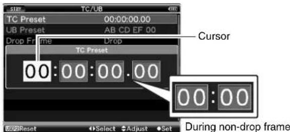
[TC Preset] Screen (During drop frame)
Memo:
- Press the [USER2] button to reset each digit to "0". The cursor moves to the time digit (left).
3 Check the values and press the Set button (●).
●The time code is set and the screen returns to [TC/UB].
●To cancel the setting, press the [CANCEL] button.
4 Press the [MENU] button.
Returns to the normal screen.
Setting Time Code and User's Bit (continued)
Presetting the User's Bit
You can add an 8-digit hexadecimal number as the user's bit to the recorded image.
![[MENU] Button Set Button (●) Cross-Shaped Button (▲▼▲▼) [CANCEL] Button [USER2] Button](/content/2026/06/1254269/images/4784ab1ed51376073dea06e5365ad89f1dc65a128dc7709aacc465c9ffa199b4.jpg)
1 Select [Main Menu]→[TC/UB]→[UB Preset] and press the Set button (●). (Page 82)
The [UB Preset] setting screen appears.
![STAY... TC/UB TC Preset 00:00:00.00 UB Preset AB CD EF 00 Drop Frame Drop Back Select Enter Back [TC/UB] Menu Screen](/content/2026/06/1254269/images/22c84c86f43aa7b383103a12bf0846a1ac1ad82bc40cca544f9d3a0a94697573.jpg)
Memo:
- When the [TC GENE.] switch is set to "REGEN", the parameter is displayed as "Regeneration" and cannot be selected.
2 Use the cross-shaped button (◀▶) to place the cursor at the item to set, then the cross-shaped button (▲▼) to change the values.
Numbers between 0 and 9 or alphabets between A and F can be specified for the user's bit.
![STAY TC/UB TC Preset 00:00:00.00 UB Preset AB CD EF 00 Drop Frame Drop UB Preset A B C D E F 0 0 [UB Preset] Screen Cursor Reset Select Adjust Set](/content/2026/06/1254269/images/4a264264d5bed9ff2c92657efab03ccac377d76aac5ef23363e5732681993f30.jpg)
Memo:
- Press the [USER2] button to reset each digit to "0". The cursor moves to the left.
3 Check the values and press the Set button (●).
●The time code is set and the screen returns to [TC/UB].
●To cancel the setting, press the [CANCEL] button.
4 Press the [MENU] button.
Returns to the normal screen.
Setting Time Code Without Opening the Menu
![[MENU] Button Set Button (●) TC 178 140 200 [CANCEL] Button Cross-Shaped Button (▲▼▲)](/content/2026/06/1254269/images/91cd8b5803a92e493aeb3cbb5853615848767c75825348f95480c0d40a8a82dd.jpg)
Memo:
●Settings cannot be made in the following cases.
- [TC GENE.] switch is set to "REGEN".
- Menu screen is displayed.
●The camera recorder is not in Camera mode.
■Required Settings Before Preset (Page 47)
- Set the [TC DISPLAY] switch to "TC".
- Set the [TC GENE.] switch to settings other than "REGEN".
■Setting Time Code
1 Hold down the [MENU] button and press the [USER1] button.
The [TC Preset] setting screen appears.
![TC Preset 00:00:00.00 Cursor [TC Preset] Screen (During drop frame)](/content/2026/06/1254269/images/a0779a5d13a143eee606e87371c18cceca5afa7c900b0a9d4f540fbfeb833126.jpg)
2 Set the time code (hour, minute, second, frame).
Use the cross-shaped button (◀▶) to place the cursor at the item to set, then the cross-shaped button (▲▼) to change the values.
Memo:
- Press the [USER2] button to reset each digit to "0". The cursor moves to the time digit (left).
3 Check the values and press the Set button (●).
●The time code is set and the screen returns to the normal screen.
●To cancel the setting, press the [CANCEL] button.
Note:
- Editing will be canceled and the screen will close under the following situations.
●The [TC DISPLAY] switch is selected during editing.
●The camera recorder is switched to the Media mode. - When editing time code, operations of the [USER1], [USER2], [USER3] buttons that are set in the [Main Menu]→[Camera Function]→[Switch Set] menu are disabled. [USER2] functions as the number reset button. (r×Page 74)
Setting User's Bit Without Opening the Menu
Memo:
●Settings cannot be made in the following cases.
- [TC GENE.] switch is set to "REGEN".
- Menu screen is displayed.
●The camera recorder is not in Camera mode.
■Required Settings Before Preset (Page 47)
- Set the [TC DISPLAY] switch to "UB".
- Set the [TC GENE.] switch to settings other than "REGEN".
Setting User's Bit
1 Hold down the [MENU] button and press the [USER1] button.
The [UB Preset] setting screen appears.

[UB Preset] Screen
2 Set the user's bit.
Use the cross-shaped button (◀▶) to place the cursor at the item to set, then the cross-shaped button (▲▼) to change the values.
Memo:
- Press the [USER2] button to reset each digit to "0". The cursor moves to the left.
3 Check the values and press the Set button (●).
- The user's bit is set and the screen returns to the normal screen.
●To cancel the setting, press the [CANCEL] button.
Note:
- Editing will be canceled and the screen will close under the following situations.
●The [TC DISPLAY] switch is selected during editing.
●The camera recorder is switched to the Media mode. - When editing time code, operations of the [USER1], [USER2], [USER3] buttons that are set in the [Main Menu]→[Camera Function]→[Switch Set] menu are disabled. [USER2] functions as the number reset button. (Page 74)
Recording Time Code in Continuation of the Recorded Time Code on SDHC card

[TC GENÉ.] Setting Switch
This camera recorder is equipped with the time code reader. Set the [TC GENE.] switch on the inner panel of the LCD to "REGEN".
When the camera recorder enters from recording standby mode to recording mode, it reads the time code already recorded on the SDHC card and records the new time code in continuation of that value.
The same data as the user's bit already recorded on the SDHC card is recorded.
Memo:
- When the [TC GENE.] switch is set to "REGEN", the framing mode of the time code follows the settings in [Drop] of the [TC/UB] menu instead of the clip settings. (Page 82)
Setting Zebra Pattern
When the luminance level range for displaying zebra patterns is specified, diagonal lines (zebra pattern) are displayed at areas with the specified luminance levels during shooting.
Specifying the Brightness (Luminance) Level Range for Displaying Zebra Pattern
![[ZEBRA ON/OFF] Switch](/content/2026/06/1254269/images/269b310448592da6546acef34cf95b8b9416639632a9fb894d727c66f5921ddb.jpg)
Specify the upper (Top1, Top2) and lower (Bottom1, Bottom2) limits of the luminance level.
1 Set the zebra display pattern.
- Select the display pattern in [LCD/VF]→[Shooting Assist]→[Zebra].


2 Specify the brightness (luminance) level range for displaying zebra pattern.
Specify the upper (Top1, Top2) and lower (Bottom1, Bottom2) limits of the luminance level in [LCD/VF]→[Shooting Assist]→[Zebra].
| Item Settings Options | ||
| Zebra Zebra | display pattern 1Pattern | 2Patterns |
| Top1 Upper | luminance limit for displaying [Zebra1] | 5% - 100%, Over (in 5% increments) |
| Bottom1 Lower | luminance limit for displaying [Zebra1] | 0% - 100% (in 5% increments) |
| Top2 Upper | luminance limit for displaying [Zebra2] | 5% - 100%, Over (in 5% increments) |
| Bottom2 Lower | luminance limit for displaying [Zebra2] | 0% - 100% (in 5% increments) |
Memo:
- "Top2" and "Bottom2" cannot be set if [Zebra] is set to "1Pattern".
- When the specified range of two zebra patterns overlaps, the two zebra patterns overlap and are displayed in a grid.

3 Display the zebra pattern.
Set the [ZEBRA ON/OFF] switch in front of the camera recorder to "ON" to display the zebra pattern at the specified range.

Setting Spot Meter
The brightness of the object during shooting is displayed. This function is useful when setting video or stage lighting or when specifying camera exposure. A cursor indicating the location and the brightness (%) of that location are displayed in the images shown on the LCD monitor and viewfinder screens.
- Zebra patterns display the brightness of output video signals. (Page 50)
- This function allows you to check the brightness of input images from the lens without depending on image processing such as gamma curve. The dynamic range of the camera recorder is 300% and a brightness range of 0% to 300% and above is displayed.
Memo:
- Spot meter may not be consistent with the zebra display range. When [Gamma] in the [Camera Process] menu is set to "Cinema" or "Film Out", the 100IRE output is not consistent with the 100% display. (Page 77) When an object of more than 300% luminance is detected, it is displayed as 300% .
![Set Button (●) Cross-Shaped Button (▲▼▲▼) [SKIN AREA/SPOT METER] Switch](/content/2026/06/1254269/images/ee21bcc54f7e9d0eefaf39de829ddf44654e6d94ba911ada6fadf9c02b06880a.jpg)
1 Select "Spot Meter" in [SKIN A./SPOT M.] of the [Main Menu]→[Camera Function]→[Switch Set] menu. ( Page 75)
2 Select one of the following from [SPOT METER]. (Page 75)
1 Select "Spot Meter" in [SKIN A./SPOT M.] of the [Main Menu]→[Camera Function]→[Switch Set] menu. ( Page 75) 2 Select one of the following from [SPOT METER]. ( Page 75)
| Item Settings | Color of frame indicating the position |
| [Max&Min] Displays the brightness (%) and positions of the brightest and darkest areas in the screen. Frames may also be stopped at the current positions. | [Max] : Green[Min] : Yellow |
| [Max] Displays the brightness (%) and position of the brightest area in the screen. Frames may also be stopped at the current positions. | Green |
| [Min] Displays the brightness (%) and position of the darkest area in the screen. Frame may also be stopped at the current positions. | Yellow |
| [Manual] Displays the brightness (%) of the specified position. | Green(Blinks in red when specifying the position) |
3 Flip the [SKIN AREA/SPOT METER] switch of the camera recorder.
The operation switches as below when the [SKIN AREA/SPOT METER] switch is flipped.
■When [Max&Min]/[Max]/[Min] is selected
①[SPOT METER ON] is displayed when the switch is flipped. Cursors appear according to the settings. The positions of the brightest (Max) and darkest (Min) areas in the screen are automatically detected with regard to the changes of the object, and the brightness of these areas are displayed.
![Cursor ([Max]:Green) MAX 230% MIN 5% Cursor ([Min]:Yellow)](/content/2026/06/1254269/images/0856ab02a00f43f81aa16939281168edcdbef3acad263039f6cde15ff761b590.jpg)
②[SPOT METER FIXED] is displayed when the switch is flipped. Automatic detection stops. Frames are fixed at the stopped positions and the brightness are displayed.
![Cursor ([Max]:Green) 230% 5% Cursor ([Min]:Yellow)](/content/2026/06/1254269/images/7852e1da657fa871e0e94b760406f8a3d5793b08703ec8203de4813893519a28.jpg)
③[SPOT METER OFF] is displayed when the switch is flipped. Displays of cursors and brightness disappear.
natural_image
Silhouette of a city skyline with skyscrapers and waterfront, no visible text or symbols④Returns to the state in ①.
Setting Spot Meter (continued)
■When [Manual] is selected
①[SPOT METER FIXED] is displayed when the switch is flipped. The brightness of the cursor position is displayed.
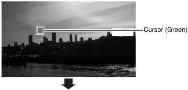
②[SPOT METER OFF] is displayed when the switch is flipped. Displays of cursors and brightness disappear.
![JVC GY-HM700U - ■When [Manual] is selected - 2](/content/2026/06/1254269/images/5cdeba4b069dd2f24e9071ed6070269750504a2690aad0167c70dd226e44b5ae.jpg)
natural_image
Silhouette of a city skyline at dusk with waterfront and reflections, no visible text or symbols③[SPOT METER SELECT] is displayed when the switch is flipped. The cursor blinks in red. Move the cursor with the cross-shaped button (▲▼◀▶) to specify the position to display the brightness. When the position is decided, press the Set button (●) or flip the switch to confirm.

④Returns to the state in ①.
Memo:
- When moving the cursor position, [SHUTTER]/[AE LEVEL] control is disabled.
- You can also decide the position of the cursor with the Set button (●).
- When the brightness is 0 % in the entire screen, the frame is fixed in the center.
Viewing Recorded Videos Immediately (Clip Review)
You can check (review) the last recorded video clip on the screen.
However, the video clip cannot be played back if the settings of the camera recorder are different from the video format (Camera Resolution/Frame & Bit Rate) of the clip. (Page 71)
Memo:
- To use this function, assign "Clip Review" to any of the [USER1], [USER2], [USER3] buttons or the [RET] button on the lens.
* [Main Menu]→[Camera Function]→[Switch Set]→[LENS RET]/[USER1]/[USER2]/[USER3]→“Clip Review” (Page 74)
![[RET] Button](/content/2026/06/1254269/images/73372da251319110df78eb5a30ce50f8df0de9647b1cb4a035efb0b5ef112664.jpg)
1 Press the button assigned with the "Clip Review" function during standby ("STBY" is displayed).
Playback of the configured section starts.
Memo:
- The video clip is played back according to the [Clip Review] settings in the [Camera Function] menu. By default setting (Last 5 sec), the last 5 seconds of the clip is played back. (Page 74)
- When playback is complete, the camera recorder exits Clip Review and returns to "STBY" (recording standby) mode.
Note:
●During Clip Review, only the [CANCEL] and [REC] buttons are enabled. Press the [CANCEL] button to cancel clip review and return to "STBY" (recording standby) mode. Press the [REC] button to cancel clip review and enter recording mode. It will take some time to start recording after the button is pressed.
- When the last clip is less than 5 seconds, the whole clip is played back.
- Only video clips in the currently selected slot can be reviewed.
- When there are no clips in the selected slot, Clip Review function is disabled.
- Clip Review is unavailable when Clip Continuous REC is paused (STBYC, red text). To operate Clip Review, use the [CANCEL] button to set to "STBYC" (white text) first. (Page 55)
- Clip Review is unavailable when the camera recorder is connected to an external equipment and the equipment is in recording state.
Assigning Functions to User Buttons
You can assign functions to the [USER1], [USER2], and [USER3] buttons.
By assigning functions to the [USER1], [USER2], and [USER3] buttons, the usability of the camera recorder is enhanced.
![[USER1], [USER2], [USER3] Buttons](/content/2026/06/1254269/images/ac8ad4cd2b0e703924393f9b49704e303f1253f3c902afbe52a469850cfd0f0a.jpg)
1 Assign functions to the [USER1], [USER2], and [USER3] buttons from the menu. (Page 74)
Set each of the [USER1], [USER2], and [USER3] items in the [Main Menu]→[Camera Function]→[Switch Set] menu.
Memo:
- Operations of the [USER1], [USER2], and [USER3] buttons are interlocked with the menu settings.
- When the menu screen is displayed, these buttons function as the menu operation buttons. (Page 66 [Basic Operations in Menu Screen])
Protecting Important Scenes (OK Mark Function)
You can append OK marks to the clips for important scenes. Clips appended with OK marks cannot be deleted, thus protecting the important clips. In addition, you can display only the clips with OK marks in the thumbnail display during Media mode.
Appending OK Marks During Recording
1 Assign the "OK Mark" function to the [RET] button on the lens from the menu.
- Select [Main Menu]→[Camera Function]→[Switch Set]→[LENS RET]→“OK Mark”. (Page 74)
- Append or delete the [OK] mark with every press of the [RET] button.
- When an OK mark is appended, "OK" appears at the top left of the status screen on the viewfinder/LCD monitor. (Page 96) (Page 103)

STATUS 1 Screen
Memo:
- Clips appended with [OK Mark] cannot be deleted from the camera recorder using [Delete Clip]. (However, they will be deleted when the SDHC card is formatted.)
- When the camera recorder is in Media mode (SD Card mode), you can delete the [OK] marks appended during recording, or append/delete [OK] marks after shooting. (E Page 64 [Appending and Deleting OK Marks])
Note:
- When the write-protect switch on the SDHC card is set (f displayed), [OK] marks cannot be appended/deleted.
Special Recording
Besides the normal recording mode, three special recording methods are available in this camera recorder. They are Pre REC, Clip Continuous REC, and Variable Frame REC. Select the mode from [Rec Mode] in the [Record Set] menu.
* Set using [Main Menu]→[Record Set]→[Rec Mode]. (Page 71)
Pre REC
This mode allows you to start video and audio recording about 3 seconds before the actual recording. You can start recording about 3 seconds before the actual recording when the camera recorder is in recording standby mode (STBYP).
Using Pre REC allows you to record a complete event without missing the initial scenes even if you start the recording late.
![Finished clip (Recorded video and audio) Records approx. 3 seconds before Press [REC] (Recording starts) Press [REC] (Recording stops)](/content/2026/06/1254269/images/656059153a9a5523796e3b3ee70d3dc6aecf2c540bd6ac34660660dce4e0b9d8.jpg)
1 Set [Rec Mode] to "Pre Rec". (Page 71)
- Set [Main Menu]→[Record Set]→[Rec Mode] to "Pre Rec".
- The status display changes to "STBY"→"STBYP".
2 Press the [REC] button to start recording in Pre REC mode.
- The status display changes to "STBYP"→"RECP" and the card slot status indicator lights up in red.
- Press the [REC] button again to pause recording. The display changes to "RECP"→"STBYP" and the card slot status indicator lights up in green.
Note:
- When the interval between start and stop recording is short, "STBYP" may not be displayed immediately after recording is complete. "RECP"→"STBYP" (STBY blinks in red)→"STBYP" is displayed.
- When the SDHC card becomes full during recording, recording stops and "STOPP" is displayed.
●Video and audio before the above mentioned time may not be recorded after recording starts in the following cases.
- Immediately after power on
- Immediately after switching from Media mode to Camera mode
- Immediately after setting [Rec Mode]
- Immediately after the end of Clip Review
- Immediately after changing file format
- Immediately after changing video format
Clip Continuous REC
In normal recording, when the recording stops, the image, audio, and accompanying data from the start till the end of the recording are recorded as one “clip” on the SDHC card. This mode allows you to consolidate several rounds of “start-stop recording” into one clip.
Example: In normal recording, three clips are generated as Recording 1, Recording 2, and Recording 3. However, recording in this mode generates only one clip.
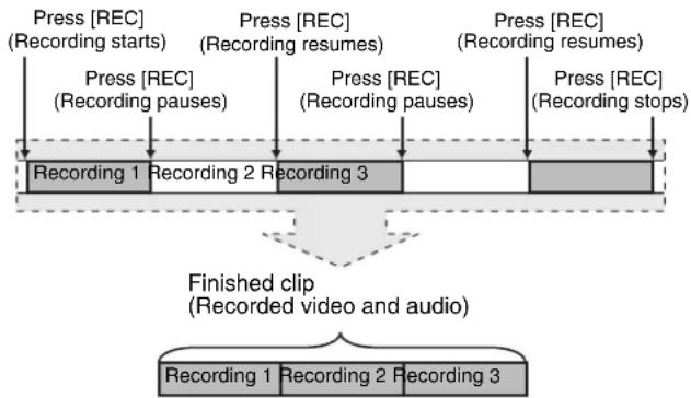
flowchart
graph TD
    A["Recording 1"] --> B["Recording 2"] --> C["Recording 3"]
    D["Recording 1"] --> E["Recording 2"] --> F["Recording 3"]
    G["Recording 1"] --> H["Finished clip (Recorded video and audio)"]
    I["Recording 2"] --> J["Finished clip (Recorded video and audio)"]
    K["Recording 2"] --> L["Finished clip (Recorded video and audio)"]
    M["Recording 3"] --> N["Finished clip (Recorded video and audio)"]
    O["Recording 3"] --> P["Finished clip (Recorded video and audio)"]
    Q["Recording 3"] --> R["Finished clip (Recorded video and audio)"]
    S["Recording 3"] --> T["Finished clip (Recorded video and audio)"]
    U["Recording 3"] --> V["Finished clip (Recorded video and audio)"]
    W["Recording 3"] --> X["Finished clip (Recorded video and audio)"]
    Y["Recording 3"] --> Z["Finished clip (Recorded video and audio)"]
    AA["Recording 3"] --> AB["Finished clip (Recorded video and audio)"]
    AC["Recording 3"] --> AD["Finished clip (Recorded video and audio)"]
    AE["Recording 3"] --> AF["Finished clip (Recorded video and audio)"]
    AG["Recording 3"] --> AH["Finished clip (Recorded video and audio)"]
    AI["Recording 3"] --> AJ["Finished clip (Recorded video and audio)"]
    AK["Recording 3"] --> AL["Finished clip (Recorded video and audio)"]
    AM["Recording 3"] --> AN["Finished clip (Recorded video and audio)"]
    AO["Recording 3"] --> AP["Finished clip (Recorded video and audio)"]
    AQ["Recording 3"] --> AR["Finished clip (Recorded video and audio)"]
    AS["Recording 3"] --> AT["Finished clip (Recorded video and audio)"]
    AU["Recording 3"] --> AV["Finished clip (Recorded video and audio)"]
    AW["Recording 3"] --> AX["Finished clip (Recorded video and audio)"]
    AY["Press [REC"] (Recording starts)] --> AZ["Press [REC"] (Recording pauses)] --> BA["Press [REC"] (Recording resumes)] --> BB["Press [REC"] (Recording resumes)] --> BC["Press [REC"] (Recording stops)] --> BD["Press [REC"] (Recording stops)]
1 Set [Rec Mode] to "Clip Continuous".
- Set [Main Menu]→[Record Set]→[Rec Mode] to "Clip Continuous". (Page 71)
- The status display changes to "STBY"→"STBYC".
2 Start recording. (Recording 1)
- Press the [REC] button to start recording in Clip Continuous mode.
- The status display changes to "STBYC"→"RECC" and the card slot status indicator lights up in red.
3 Pause recording.
- Press the [REC] button again to pause recording. The display changes to "REC" → "STBY" (red text).
- The card slot status indicator remains lighted in red.
Memo:
- When the [CANCEL] button is pressed while the camera recorder is paused (STBYC), the display changes to "STBYC" (red text) → "STBYC" (blinking red text)
→“STBYC” (white text). A “clip” is generated. The card slot status indicator lights up in green.
4 Resume recording. (Recording 2)
- Press the [REC] button again to resume recording. The display changes to "STBYC" (red text) → "RECC".
- The card slot status indicator remains lighted in red.
5 Pause recording.
- Press the [REC] button again to pause recording. The display changes to "REC" → "STBY" (red text).
- The card slot status indicator remains lighted in red.
6 Resume recording. (Recording 3)
- Press the [REC] button again to resume recording. The display changes to "STBYC" (red text) → "RECC".
●The card slot status indicator remains lighted in red.
7 Press and hold the [REC] button.
- Recording stops and the display changes to "REC C "→"STBY C ". A "clip" is generated
●The card slot status indicator lights up in green.
8 Press the [REC] button again.
- The status display changes to "STBYC"→"RECC" and the card slot status indicator lights up in red.
- A new "clip" is generated from here.
Memo:
- The following operations are unavailable while recording is paused (STBYC, red text).
- Clip Review (Page 52)
●Switching SDHC card slots - Switching operation mode (Page 7)
- Files are split into sizes of 4 GB (or 30 minutes) regardless of the menu settings.
Note:
- Do not remove the SDHC card during recording (REC, red text) or recording pause (STBY, red text).
- To remove the SDHC card in “Clip Continuous” mode, press the [CANCEL] button, check that “STBYC” (white text) is displayed and the card slot status indicator is lighted in green before you remove the card.
- When the SDHC card becomes full during recording, recording stops and "STOPC" is displayed.
- When the [POWER] switch is turned off during recording or recording pause, recording stops and power is cut off after a clip is generated.
- If the power is cut off due to low battery power, a proper clip may not be generated.
Special Recording (continued)
Variable Frame REC
Shooting in this mode allows you to obtain smooth slow motion or quick motion videos.
Using different frame rate settings for recording and playback, videos captured at normal speed can be played back more smoothly than those in low or high speed playback.
To enable Variable Frame REC, the following two settings are required at the same time.
- [Camera Resolution] in the [Record Format] menu is set to "1280x720".
- [Frame & Bit Rate] in the [Record Format] menu is set to "30p(HQ)", "24p(HQ)", or "25p(HQ)".
■Number of Frames that can be Set
1 Set [Camera Resolution] to "1280x720", then set [Frame & Bit Rate]. (Page 71)
Set [Frame & Bit Rate] to “30p(HQ)”, “24p(HQ)”, or “25p(HQ)”.
2 Set [Rec Mode] to "Variable Frame". (Page 71)
Set [Main Menu]→[Record Set]→[Rec Mode] to "Variable Frame".
3 Select a recording frame rate from [Frame Rate]. (Page 71)
The selectable frame rates are as shown below.
| Record Format $ selectable Shooting Frame Rate | ||||||||||
| 1280x720 | 30p(HQ) | 10 | 12 | 15 | 20 | 24 | 30 | 40 | 48 | 60 |
| 24p(HQ) | — | 10 | 12 | 15 | 20 | 24 | 30 | 40 | 48 | |
| 25p(HQ) | — | — | 10 | 12.5 | 20 | 25 | 40 | 50 | — | |
| Effect during playback Quick motion Standard Slow motion | ||||||||||
Memo:
- When [AE LEVEL] in the [Main Menu]→[Camera Function]→[Switch Set] menu is set to "AE LEVEL/VFR", you can use the cross-shaped button (◀▶) to select the frame rate during Variable Frame REC. In modes other than Variable Frame REC, the cross-shaped button (◀▶) functions as the [AE LEVEL] setting button. (◀ Page 75)
Note:
●The recording frame rate cannot be changed during recording. To change the frame rate, stop the recording first and perform the change.
- When the [TC GENE.] switch located on the inner panel of the LCD is set to "FREE", videos are recorded in REC (RecRun) time code.
●Audio cannot be recorded. A mark appears in the audio level meter display. (Page 96)
- Depending on the settings, images beyond the recording stop position may be recorded and it may take time for the camera recorder to enter "STBY" mode.
Playing Back Recorded Clips
To play back clips recorded on SDHC cards, switch to the Media mode (SD Card mode).
Press the [CAM/MEDIA] selection button in Camera mode to enter SD Card mode. A thumbnail screen of the clips recorded on the SDHC card is displayed.
You can play back the selected clip on the thumbnail screen.
Memo:
- When an SDHC card without any clips is inserted, "No Clips" is displayed.
Operation Buttons
Use the operation buttons on the side control panel of the camera recorder to operate the thumbnail screen.
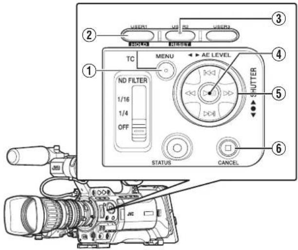
| Name Description | |
| 1[MENU] Button | Displays the thumbnail screen menu. Press this button to close the menu screen during menu display and return to the normal screen. |
| 2[USER1] Button | Appends (or deletes) an OK mark on the selected clip. |
| 3[USER2] Button | Deletes the selected clip. |
| 4Set (Play) Button | Sets the values and items. (Confirm) Plays back the selected clip. |
| 5Cross-Shaped Button (▲▼◀▶) | ▲: Moves the cursor upward.▼: Moves the cursor downward.◀: Moves back to the previous item.▶: Moves forward to the next item. (To enter sub-menus or display pop-up menus.) |
| 6[CANCEL] (Stop) Button | Cancels settings and returns to the previous screen.Stops video playback. |
Thumbnail Screen
The thumbnail screen is available in "No Detailed Properties (4x3 thumbnails)" and "Detailed Properties (4x1 thumbnails)" displays.
Use the thumbnail menu [Detailed Properties] to switch display. (Page 61)
The first frame of the recorded clip on the SDHC card is displayed as the thumbnail.
Thumbnails are displayed in order of recording from the oldest to most recent.
■ No Detailed Properties (4x3 Thumbnails) Screen

| Name Description | |
| 1Cursor | Indicates the selected clip. Use the cross-shaped button (▲▼▲) to move the cursor. After power is turned on and SDHC card is inserted, or when the camera recorder is switched to Media mode (SD Card mode), the cursor is positioned on top of the latest clip. When the camera recorder changes to the thumbnail screen during playback, the cursor is positioned on the clip that was played back. If you play back the same clip again, it will continue from where it was left off.The default position of the cursor when SDHC card slot is switched is on the previously selected clip before the switch.■Example of the moving order of the cursor (total 22 clips) |
Playing Back Recorded Clips (continued)
Thumbnail Screen (continued)
■No Detailed Properties (4x3 Thumbnails) Screen (continued)

| Name Description | |
| 2SDHC Card | Displays the status of the inserted SDHC card, selected SDHC card, write-protect switch, and the need for restoring. Use the [SLOT SELECT] switch to switch slots. Clips in slot A and B cannot be displayed at the same time.A#: Write-protect switch of the SDHC card in slot A is set.B!: SDHC card in slot B needs to be restored or formatted, or is an unsupported SDHC card. |
| 3File Format | Shows the file format of the currently displayed clips. Clips of other [File Format] will not be displayed.* Depends on the settings in [Record Set]→[Record Format]→[File Format] of the [Main Menu] screen. (Page 71) |
| Name Description | |
| 4Video Format | Displays the video format (Camera Resolution/Frame Rate) that allows playback and thumbnail display.Available in 4 types: [1080/60i, 30p, 24p],[1080/50i, 25p], [720/60p, 30p, 24p], and[720/50p, 25p]. Clips of other video formats are represented in alternative display. Clips that are in alternative display cannot be played back with the current video format settings.1A clip with corrupted management information. It cannot be played back even if you press the playback button.2A clip that cannot be played back nor displayed in thumbnail with the current video format settings. It cannot be played back even if you press the playback button. The format of the clip is displayed.* Depends on the settings in [Record Set]→[Record Format]→[Frame & Bit Rate] of the [Main Menu] screen. (Page 71) |
| 5Number of Clips | Displays the [running number/total number of clips] of the displayed clips. |
| 6Remaining Battery Power | : Ample battery power.: Slightly reduced battery power.: Low battery power.: Empty battery power. (Blinks in red): External power supply connected.Memo:If the battery in use is not a recommended one, the battery mark which indicates the battery level may not appear. |
| 7Scroll Bar | Indicates the scroll position.When there is a black space below the scroll bar (white), this indicates further pages.When the scroll bar (white) is at the bottom, this indicates the last page. |
| 8Thumbnail Text | Displays the time code or date/time at the start of clip recording. Date/time is displayed in the local time of the shooting location.Set whether to display “TC” or “Date/Time” in the thumbnail menu [Thumbnail Text].(Page 61)Data/time display depends on the settings in[LCD/VF]→[Status Display]→[Date Style] of the [Main Menu] screen. (Page 85)Time is displayed in 24-hour display regardless of the [Time Style] setting. |
| 9Clip Mark | Displays clip information (properties).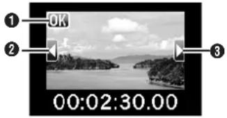 1OK MarkClip is appended with OK mark.Memo:●Clips appended with OK marks cannot be deleted on the camera recorder.2Continued From MarkThis mark indicates that the current clip is continued from another SDHC card when recording is divided and made on several SDHC cards.3Continue MarkThis mark indicates that the current clip will continue to another SDHC card when recording is divided and made on several SDHC cards. 1OK MarkClip is appended with OK mark.Memo:●Clips appended with OK marks cannot be deleted on the camera recorder.2Continued From MarkThis mark indicates that the current clip is continued from another SDHC card when recording is divided and made on several SDHC cards.3Continue MarkThis mark indicates that the current clip will continue to another SDHC card when recording is divided and made on several SDHC cards. |
| 10Operation Guide | Guide for the current operation buttons. |
| Moves the clip cursor to the top/bottom/left/right. | |
| Plays back the selected clip. | |
| Appends an OK mark to the selected clip.This is displayed when an OK mark is not appended to the clip. (Page 64)Memo:●This is disabled when the SDHC card is locked. (Displayed in gray) | |
| Deletes the OK mark from the selected clip.This is displayed when an OK mark is appended to the clip. (Page 65)Memo:●This is disabled when the SDHC card is locked. (Displayed in gray) | |
| Deletes the selected clip.(Page 62) | |
Playing Back Recorded Clips (continued)
Thumbnail Screen (continued)
■Detailed Properties (4x1 Thumbnails) Screen
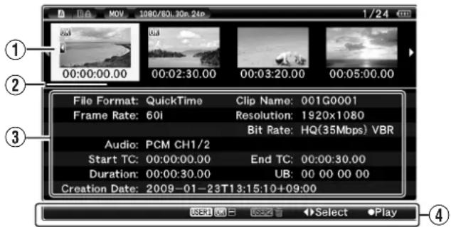
| Name Description | |
| 1Cursor | Indicates the selected clip. Use the cross-shaped button (◀▶) to move the cursor. After power is turned on and SDHC card is inserted, or when the camera recorder is switched to Media mode (SD Card mode), the cursor is positioned on top of the latest clip. When the camera recorder changes to the thumbnail screen during playback, the cursor is positioned on the clip that was played back. If you play back the same clip again, it will continue from where it was left off. The default position of the cursor when SDHC card slot is switched is on the previously selected clip before the switch.■Example of the moving order of the cursor (total 6 clips) |
| 2Scroll Bar | Indicates the scroll position.When there is a black space on the right of the scroll bar (white), this indicates further pages.When the scroll bar (white) is at the right end, this indicates the last page. |
| Name Description | |
| 3Detailed Properties | Shows the detailed properties of the selected clip. The following information is displayed. File Format : File formatClip Name : Clip nameResolution : Image sizeFrame Rate : Frame rateBit Rate : Bit rateAudio : Audio formatStart TC : Time code at the start of recordingEnd TC : Time code at the end of recordingDuration : Clip lengthUSB : User's bitCreation Date : Date createdMemo:____The information of time and date displays in the following order, Year, Month, Date, Time, Minute, Second and Time zone.“-” is the break character between Year, Month and Date for each, and “:” is the break character between Time, Minute and Second for each, and “T” is the break character Date and Time.“Z” displays behind Time when Time zone is set to “UTC+00:00”. (Time and date display example)In case of “UTC+00:00” 21:18:50 on March 4th in 2009 (Western European time zone):“2009-03-04T21:18:50Z”In case of “UTC-05:00” 10:13:15 on March 19th in 2009 (North American Eastern time zone).“2009-03-19T10:13:15-05:00”Variable Frame : Variable frame (only in Variable Frame REC) |
| 4Operation Guide | Guide for the current operation buttons. |
| Select | Moves the clip cursor to the left/right. |
| Play | Plays back the selected clip. |
| USER1 OK | Appends an OK mark to the selected clip. This is displayed when an OK mark is not appended to the clip. (Page 64)Memo:____This is disabled when the SDHC card is locked. (Displayed in gray) |
| USER1 OK | Deletes the OK mark from the selected clip. This is displayed when an OK mark is appended to the clip. (Page 65)Memo:____This is disabled when the SDHC card is locked. (Displayed in gray) |
| USER2 | Deletes the selected clip. (Page 62) |
Playing Back
Use the operation buttons on the side control panel of the camera recorder to play back.

| Name Description | |
| 1Button | Plays back/pauses the selected clip. |
| 2Button<> | Skips in the reverse or forward direction. |
| <=>Button | Fast forwards in the reverse or forward direction. |
| 3Button | Stops playback. |
1 Select the clip to play back on the thumbnail screen.
Select the clip to play back with the cross-shaped button (▲▼◀▶).
2 Press the playback/pause button.
Playback of the selected clip starts.
■Time Code Playback
Time code or user's bit recorded on an SDHC card can be displayed on the LCD monitor and viewfinder.
Memo:
- When [HD/SD-SDI Out] in the [A/V Out] menu is set to "HD-SDI" or "SD-SDI", time code is also output from the [HD/SD-SDI] output terminal. (Page 86)
- User's bit output from the [HD/SD-SDI] output terminal is used as a flag to determine valid video signals. Therefore, accurate values will not be output.
- If a section without time code is played back, the time code will stop. However, playback will continue.
Thumbnail Menu
Press the [MENU] button during thumbnail display to display the thumbnail menu.
Press the [MENU] button during menu display to cancel the settings and exit the menu.

Thumbnail Menu Screen
| Item Function | |
| Media info Displays the information screen of the SDHC card. | |
| Detailed Properties | For selecting the display method of the thumbnail screen.If a check is selected, the thumbnail screen will be displayed as [Detailed Properties (4x1 Thumbnail) Screen]. (Page 60) |
| Thumbnail Text... | For selecting the display method for the thumbnail text on the thumbnail screen. |
| TC Displays the recording start time code at the thumbnail text display area (below the thumbnail). | |
| Date/Time Displays the recording start date/time at the thumbnail text display area (below the thumbnail). | |
| Delete Clip... | For deleting clips. (Page 62) |
| One Clip | Deletes the selected clip. |
| All Clips Deletes all clips that are displayed. | |
| Main Menu... | Opens the [Main Menu] screen. (Page 70) |
| Exit | Exits and closes the menu. |
Deleting Clips
For deleting clips.
![[MENU] Button Set Button (●) Cross-Shaped Button (▲▼▲▼) [CANCEL] Button [USER2] Button](/content/2026/06/1254269/images/87c8df1fba80c8cf5f52818880f34152da863925cec9ece5861d4965cda08fc6.jpg)
Note:
- Clips appended with OK marks cannot be deleted on the camera recorder.
- Read-only clips can be deleted on a PC.
Deleting One Clip
You can delete a selected clip with any of the following operations.
①Press [USER2] button when menu is not displayed.
② Perform [Delete Clip]→[One Clip] in thumbnail menu.
Memo:
- A clip cannot be deleted with the [USER2] button and menu operation ([Delete Clip]→[One Clip]) under the following situations.
●A clip with OK mark is selected. - Write-protect switch of the SDHC card is set (displayed).
■During Thumbnail Screen
■Deleting with [USER2] button
1 Select the clip to delete.
Select the clip to delete with the cross-shaped button (▲▼◀▶).

2 Press the [USER2] button.
A screen to confirm deletion appears.
3 Use the cross-shaped button (▲▼) to select [Delete] and press the Set button (●).
Deleting starts.


Memo:
- Button operations are unavailable during deletion. The deleting operation cannot be canceled.
- The cursor moves to the next clip (or previous clip if a next clip does not exist) after deletion.
■ Deleting with [Delete Clip]→[One Clip] in the menu
1 Select the clip to delete.
Select the clip to delete with the cross-shaped button (▲▼◀▶).

2 Press the [MENU] button.
The thumbnail menu screen appears.
3 Select [Delete Clip]→[One Clip] and press the Set button (●).
A screen to confirm deletion appears.
4 Use the cross-shaped button (▲▼) to select [Delete] and press the Set button (●).
Deleting starts.

Memo:
- Button operations are unavailable during deletion. The deleting operation cannot be canceled.
- The cursor moves to the next clip (or previous clip if a next clip does not exist) after deletion.
■During Playback or Pause Screen
■Deleting with [USER2] button
1 Press [USER2] button during clip playback.
A screen to confirm deletion appears.
2 Select [Delete] and press the Set button (●).
Deleting starts.
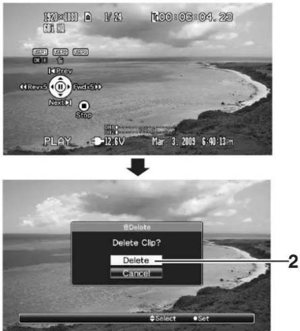

Deleting All Clips
Deletes all clips that are displayed.
1 Press the [MENU] button.
The thumbnail menu screen appears.
2 Select [Delete Clip]→[All Clips] in the menu.
A screen to confirm deletion appears.
3 Select [Delete] and press the Set button (●).
Deleting starts.
Memo:
- Button operations are unavailable during deletion. The deleting operation cannot be canceled.
●The time taken to delete clips depends on the number of clips to be deleted.
Appending and Deleting OK Marks
You can append OK marks to the clips for important scenes.
Clips appended with OK marks cannot be deleted, thus protecting the important clips.
When the camera recorder is in Media mode (SD Card mode), you can delete the OK marks appended during recording, or append/delete OK marks after shooting.
![[MENU] Button Set Button (●) Cross-Shaped Button (▲▼▲▼) [CANCEL] Button [USER1] Button](/content/2026/06/1254269/images/2fa772dee0aee51be22ea0a2e71746398411aa76d1828764a08e223a3644ef96.jpg)
Appending OK Marks
■During Thumbnail Screen
1 Select a clip without an OK mark and press the [USER1] button.
An OK mark is appended to the clip.


Memo:
●The [USER1] button is disabled (displayed in gray) and OK marks cannot be appended when the write-protect switch of the SDHC card is set ( displayed).
- "OK Mark Added..." is displayed when changing marks and other operations are unavailable.
■During Playback or Pause Screen
1 Press [USER1] button during clip playback. An OK mark is appended to the clip.

Memo:
●The clip pauses when an OK mark is appended or deleted during playback.
Deleting OK Marks
■During Thumbnail Screen
1 Select a clip to delete OK mark and press the [USER1] button.
The OK mark is deleted.

Memo:
- The [USER1] button is disabled (displayed in gray) and OK marks cannot be deleted when the write-protect switch of the SDHC card is set ( displayed).
- "OK Mark Added..."/“OK Mark Deleted...” is displayed when changing marks and other operations are unavailable.
■During Playback or Pause Screen
1 Press the [USER1] button when playing back a clip appended with OK mark.
The OK mark is deleted.

Basic Operations in Menu Screen
Press the [MENU] button on the side control panel of the camera recorder to display the menu screen on the LCD monitor and viewfinder.
Various settings for shooting and playback can be configured on the menu screen.
There are two types of menu screens - [Main Menu] and [Favorites Menu].
[Main Menu] contains all the setting items of the camera recorder, classified according to functions and uses, while [Favorites Menu] allows users to customize the menu items freely. (rPage 90)
The operating procedures and main screen displays are the same for both menus.
The menu screen can also be displayed on external monitors connected to the video signal output terminal.
( Page 86 [Analog Out Char.])
Page 86 [SDI Out Char.]
Operation Buttons
Use the operation buttons on the side control panel of the camera recorder to operate the menu.

| Name Description | |
| 1[MENU] Button | Displays the menu screen.●[Main Menu] is displayed by default when pressed.●During normal usage, [Main Menu] is displayed if the previous menu operation ended at [Main Menu], and [Favorites Menu] if the previous menu operation ended at [Favorites Menu].Press this button to close the menu screen during menu display and return to the normal screen. |
| 2[USER1] Button | Adds the selected menu or submenu item to the [Favorites Menu]. (s:Page 90) |
| 3[USER2] Button | Resets settings in the [TC Preset] or [UB Preset] setting screen. This button is disabled in other screens. |
| 4Set button (●) | Sets the values and items. |
| 5Cross-Shaped Button (▲▼◀ ▶) | ▲: Moves the cursor upward.▼: Moves the cursor downward.◀: Moves back to the previous item.▶: Moves forward to the next item. |
| 6[CANCEL] Button | Cancels settings and returns to the previous screen. |
| Name Description | |
| 7[STATUS]Button | Switches between the [Main Menu] and [Favorites Menu] screens. |
Display and Description of the Menu Screen
■Selecting Menu Items

| Name Description | |
| 1Status Display | Displays the current states, such as recording and playback.Same display as the status screen.■During Camera mode:[STBY], [REC], etc. (※Page 94)■During Media mode (SD Card mode):[PLAY], [STILL], etc. (※Page 101) |
| 2Cursor | Indicates the selected item. Use the cross-shaped button (▲▼) to move the cursor. |
| 3Menu Item | Displays the names of the menu item and sub-menu.Menu items with [...] after them indicates that there is a sub-menu to access. |
| 4Fixed Item | Items that cannot be changed are displayed in gray and cannot be selected. |
| 5[Back] Back | Select [Back] and press the Set button (●) to return to the previous level. |
| 6Menu Title | Title of the currently displayed menu. |
| 7Remaining Battery Power | : Ample battery power.: Slightly reduced battery power.: Low battery power.: Empty battery power. (Blinks in red): External power supply connected.Memo:●If the battery in use is not a recommended one, the battery mark which indicates the battery level may not appear. |
| 8Header | Indicates the current menu type with the line color.Blue : [Main Menu] ScreenGreen : [Favorites Menu] (Operation screen)Magenta: [Favorites Menu] (Editing screen) |
| 9Scroll Bar | Indicates the scroll position. |
| 10Setting Values | Setting values for the menu items.For menus with sub-menus, values are not displayed. |
| 11Operation Guide | Guide for the current operation buttons. |
■Changing Setting Values

| Name Description | |
| 1Menu Item to Change | Menu item to be changed.A list of setting values 3 appears in a pop-up. |
| 2Operation Guide | Guide for the current operation buttons. |
| 3List of Setting Values | A pop-up displaying a list of setting values for selection.The height of the pop-up depends on the number of settings available. Use the scroll bar 4 to confirm the current display status. |
| 4Scroll Bar | Indicates the scroll position. |
| 5Cursor | Indicates the selected item. Use the cross-shaped button (▲▼) to move the cursor. |
| 6Setting Values Before Change | Setting values before changing. ● appears at the beginning of the item. |
Text Input with Software Keyboard
Use the software keyboard to enter the [Scene File]/[Picture File] subname and [Clip Name Prefix].
■ [Scene File]/[Picture File] (Page 112)

■ [Clip Name Prefix] (Page 72)

| Name Description | |
| 1CharacterEntry Field | Field for entering the title.You can enter up to 8 characters for the [Scene File]/[Picture File] subname or up to 4 characters for the [Clip Name Prefix]. |
| 2CharacterCursor | Select a character using the key cursor 4, and press the Set button (●) to input the selected character at the position of the character cursor. The character cursor moves to the next position on the right each time a character is input.The cursor can be moved using the arrow keys 6. |
| 3CharacterKeys | Use the cross-shaped button (▲▼◀▶) to move the key cursor 4 to the character you want to enter. |
| 4Key Cursor | Indicates the currently selected character or item. Use the cross-shaped button (▲▼◀▶) to move the cursor. |
| 5ConfirmationButtons | Select [Set]/[Store] and press the Set button (●) to confirm the title.Select [Cancel] and press the Set button (●) on the side control panel of the camera recorder to abort character input and return to the previous screen. |
| 6Arrow Keys | Moves the position of the character cursor 2. |
| 7[BS]BackspaceKey | Select [BS] and press the Set button (●) on the side control panel to delete the character on the left of the character cursor 2. |
| 8[SP] SpaceKey | Select [SP] and press the Set button (●) on the side control panel to enter a space at the current position of the character cursor 2. |
Menu Screen Hierarchical Chart
Main Menu... (Page 70)
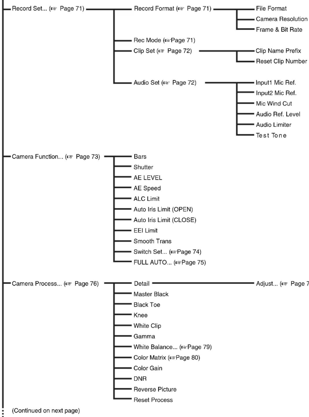
flowchart
graph TD
    A["Record Set... (Page 71)"] --> B["Record Format (Page 71)"]
    B --> C["File Format"]
    B --> D["Camera Resolution"]
    B --> E["Frame & Bit Rate"]
    B --> F["Rec Mode (Page 71)"]
    B --> G["Clip Set (Page 72)"]
    G --> H["Clip Name Prefix"]
    G --> I["Reset Clip Number"]
    G --> J["Audio Set (Page 72)"]
    J --> K["Input1 Mic Ref."]
    J --> L["Input2 Mic Ref."]
    J --> M["Mic Wind Cut"]
    J --> N["Audio Ref. Level"]
    J --> O["Audio Limiter"]
    J --> P["Test Tone"]

    Q["Camera Function... (Page 73)"] --> R["Bars"]
    R --> S["Shutter"]
    R --> T["AE LEVEL"]
    R --> U["AE Speed"]
    R --> V["ALC Limit"]
    R --> W["Auto Iris Limit (OPEN)"]
    R --> X["Auto Iris Limit (CLOSE)"]
    R --> Y["EEI Limit"]
    R --> Z["Smooth Trans"]
    R --> AA["Switch Set... (Page 74)"]
    R --> AB["FULL AUTO... (Page 75)"]

    AC["Camera Process... (Page 76)"] --> AD["Detail"]
    AD --> AE["Master Black"]
    AD --> AF["Black Toe"]
    AD --> AG["Knee"]
    AD --> AH["White Clip"]
    AD --> AI["Gamma"]
    AD --> AJ["White Balance... (Page 79)"]
    AD --> AK["Color Matrix (Page 80)"]
    AD --> AL["Color Gain"]
    AD --> AM["DNR"]
    AD --> AN["Reverse Picture"]
    AD --> AO["Reset Process"]

    style A fill:#f9f,stroke:#333
    style Q fill:#f9f,stroke:#333
    style AC fill:#f9f,stroke:#333
Memo:
- A [Back] item (omitted in the chart) can be found at the end of each menu item. Select [Back] and press the Set button (●) to return to the previous level.
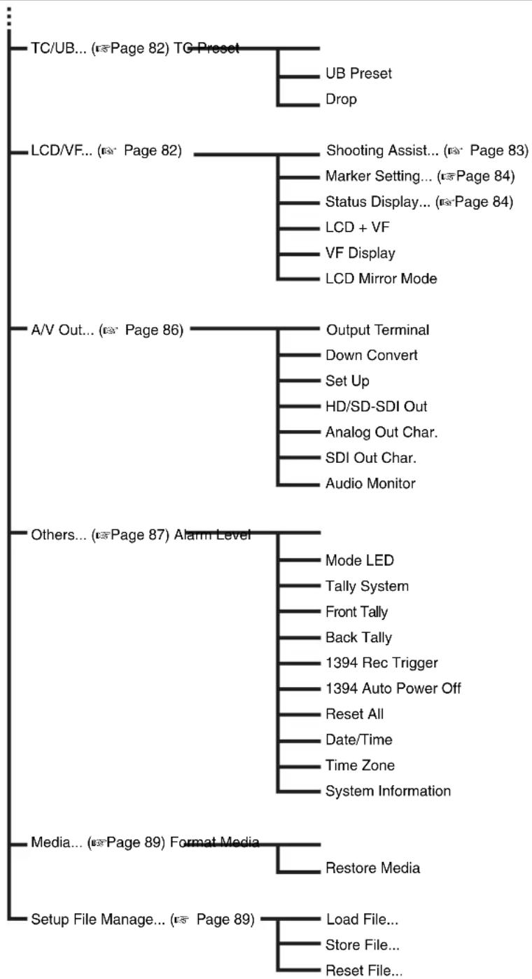
flowchart
graph TD
    A["TC/UB... ( page 82) TG Preset"] --> B["UB Preset"]
    A --> C["Drop"]
    D["LCD/VF... ( page 82)"] --> E["Shooting Assist... ( page 83)"]
    D --> F["Marker Setting... ( page 84)"]
    D --> G["Status Display... ( page 84)"]
    D --> H["LCD + VF"]
    D --> I["VF Display"]
    D --> J["LCD Mirror Mode"]
    K["A/V Out... ( page 86)"] --> L["Output Terminal"]
    K --> M["Down Convert"]
    K --> N["Set Up"]
    K --> O["HD/SD-SDI Out"]
    K --> P["Analog Out Char."]
    K --> Q["SDI Out Char."]
    K --> R["Audio Monitor"]
    S["Others... ( page 87) Alarm Level"] --> T["Mode LED"]
    S --> U["Tally System"]
    S --> V["Front Tally"]
    S --> W["Back Tally"]
    S --> X["1394 Rec Trigger"]
    S --> Y["1394 Auto Power Off"]
    S --> Z["Reset All"]
    S --> AA["Date/Time"]
    S --> AB["Time Zone"]
    S --> AC["System Information"]
    AD["Media... ( page 89) Format Media"] --> AE["Restore Media"]
    AF["Setup File Manage... ( page 89)"] --> AG["Load File..."]
    AF --> AH["Store File..."]
    AF --> AI["Reset File..."]
Memo:
- A [Back] item (omitted in the chart) can be found at the end of each menu item. Select [Back] and press the Set button (●) to return to the previous level.
Main Menu Screen
Some menus cannot be set depending on the operating mode or status of the camera. These items are displayed in gray, and they cannot be selected.
| Item Function | |
| Record Set... | Menu screen for specifying video or audio settings during shooting and playback.The cursor does not move to this item during recording or in Media mode. (Page 71) |
| Camera Function... | Menu screen for specifying operation settings during shooting.The cursor moves to this item only in Camera mode. (Page 73) |
| Camera Process... | Menu screen for adjusting the quality of camera images.The cursor does not move to this item in Media mode.(Page 76) |
| TC/UB... | Menu screen for setting time code and user's bit.The cursor does not move to this item during recording.(Page 82) |
| LCD/VF... | Item for specifying settings related to the LCD monitor or viewfinder screen.This menu screen can be used to specify settings related to the Focus Assist mode, zebra pattern display, screen size, marker, and safety zone. In addition, it is also used for selecting whether to display characters on the LCD monitor or viewfinder screen, as well as for adjusting the picture quality of the LCD monitor screen.The cursor does not move to this item in Media mode.(Page 82) |
| A/V Out... | Item for specifying connection settings with external devices.(Page 86) |
| Others... | Menu screen for specifying the settings of other functions.Use this item to adjust the alarm volume, front/back tally lamp settings, status indicator, 1394 input settings, date/time, time zone, and other settings. It can also be used to reset the menu settings to their default values.(Page 87) |
| Media... | Item for formatting or restoring the SDHC card. (Page 89) |
| Setup File Manage... | Displays the [Setup File Manage] menu screen.Settings of the menu screen can be saved as a file on the camera recorder or an SDHC card, and the saved settings can be loaded when necessary.The cursor does not move to this item during recording or in Media mode.(Page 89) |
| Exit | Select this item and press the Set button (●) to return to the normal screen. |
Record Set Menu
Record Format Menu
* Default values are indicated in bold characters.
| Item Setting Values Function | ||
| File Format | QuickTimeMP4 | For selecting the format of the file to be recorded to the SDHC card.Note:“MP4” can only be selected when KA-MR100G (Memory Recorder) is connected. |
| Camera Resolution | 1920x10801440x1080, 1280x720 | For selecting the size of the recorded images. (Horizontal x vertical)The selectable values of [Frame & Bit Rate] vary according to the setting of this item. |
| Frame & Bit Rate | For selecting the frame rate and encoding bit rate.Selection can be made from 19 combinations of frame rate (60p, 50p, 30p, 25p, 24p, 60i, 50i) and bit rate (HQ(35Mbps) VBR), (SP(25 Mbps/19 Mbps) CBR). The selectable items vary according to the [File Format] and [Camera Resolution] settings. | |
| When [Camera Resolution] is “1280x720” | 60p(HQ) (U model),60p(SP), 30p(HQ),30p(SP),50p(HQ) (E model),50p(SP), 25p(HQ),25p(SP), 24p(HQ),24p(SP) | |
| When [Camera Resolution] is “1440x1080”, and [File Format] is “QuickTime” | 60i(HQ) (U model),60i(SP),50i(HQ) (E model),50i(SP) | |
| When [Camera Resolution] is “1440x1080”, and [File Format] is “MP4” | 60i(SP) (U model),50i(SP) (E model) | |
| When [Camera Resolution] is “1920x1080” | 60i(HQ) (U model),30p(HQ),50i(HQ) (E model),25p(HQ), 24p(HQ) | |
Rec Mode Menu
| Item Setting Values Function | ||
| Rec Mode | NormalPre RecClip ContinuousVariable Frame | For selecting the record mode for recording to the SDHC card. (⇨ Page 54)Memo:[Variable Frame] is selectable when [Camera Resolution] is set to “1280x720”, and [Frame & Bit Rate] is set to “30p(HQ)”, “24p(HQ)”, or “25p(HQ)”. |
| Frame Rate | For setting the recording [Frame Rate] when [Rec Mode] is set to [Variable Frame].Memo:When [AE LEVEL] in the [Main Menu]→[Camera Function]→[Switch Set] menu is set to “AE LEVEL/VFR”, you can use the cross-shaped button (◀▶) to select the frame rate during Variable Frame REC. In modes other than Variable Frame REC, the cross-shaped button (◀▶) functions as the [AE LEVEL] setting button. (⇨Page 75)When [Frame Rate] is changed and the shutter speed becomes a value that is invalid for the current [Frame Rate], the shutter speed is automatically changed to match the current [Frame Rate]. | |
| When [Frame & Bit Rate] is “30p(HQ)” | 60, 48, 40,30,24, 20, 15, 12, 10 | |
| When [Frame & Bit Rate] is “24p(HQ)” | 60, 48, 40, 30,24,20, 15, 12, 10 | |
| When [Frame & Bit Rate] is “25p(HQ)” | 50, 40,25,20, 15, 12.5, 10 | |
Record Set Menu (continued)
Clip Set Menu
* Default values are indicated in bold characters.
| Item Setting | Values Function | |
| Clip Name Prefix | xxxG(The default value of xxx is the last 3 digits of the serial number.) | For setting the first 4 characters of the name of the clip file to be recorded to the SDHC card.Enter any of the 38 characters including alphabets (upper case), numbers (0 to 9), “_” (underscore), and “-” (hyphen) using the software keyboard.( eF Page 67 [Text Input with Software Keyboard]) |
| Reset Clip Number | — | For assigning a new number to (Clip Number) by resetting it (0001). Select [Reset] and press the Set button (●) to reset the number.When other clips exist on the SDHC card, the smallest available number is used after reset.Example: If the [Clip Name Prefix] is “ABCD”, and “ABCD0001” already exists on the SDHC card, “ABCD0002” will be assigned. |
Audio Set Menu
| Item Setting | Values Function | |
| Input1 Mic Ref. | -50dB-60dB | For setting the reference input level when the [AUDIO INPUT1] button is set to “MIC” or “MIC+48V”.-50dB : Sets -50 dB as the reference value.-60dB : Sets -60 dB as the reference value. |
| Input2 Mic Ref. | -50dB-60dB | For setting the reference input level when the [AUDIO INPUT2] button is set to “MIC” or “MIC+48V”.-50dB : Sets -50 dB as the reference value.-60dB : Sets -60 dB as the reference value. |
| Mic Wind Cut | Both Input2 Input1 Off | For selecting whether to cut the low frequencies of the audio input signals (low-cut) when the [AUDIO INPUT 1/2] button is set to “MIC” or “MIC+48V”. Set this item to reduce wind noise from the microphone.Both : Enables low-cut on both the [INPUT1] and [INPUT2] terminals.Input2 : Enables low-cut on the audio of the [INPUT2] terminal only.Input1 : Enables low-cut on the audio of the [INPUT1] terminal only.Off : Disables low-cut. |
| Audio Ref. Level | -12dB-20dB | For setting the audio reference level to be recorded to the SDHC card. (Applies to both [CH1/CH2].)-20dB : Outputs signals of the reference level when the meter is at -20 dBFS.-12dB : Outputs signals of the reference level when the meter is at -12 dBFS. |
| Audio Limiter | On Off | For specifying whether to trigger the limiter when the [AUDIO SELECT CH-1/CH-2] switch is set to “MANUAL”.On : Triggers the limiter when excessive audio signals are input, and compresses the recording level.Off : Does not trigger limiter. |
| Test Tone | On Off | For specifying whether to output the audio test signals (1 kHz) during color bar output.On : Audio test signals are output.Off : Audio test signals are not output. |
Camera Function Menu
* Default values are indicated in bold characters.
| Item Setting | Values Function | |
| Bars | OnOff | For setting whether to output color bars.On : Color bars are output.Off : Color bars are not output.Memo: ·When the [FULL AUTO] switch on the camera recorder is set to “ON”, and [Bars] in the [FULL AUTO] menu is set to “Off”, this item is set to “Off” automatically. (Page 75) |
| Shutter | EEIVariableStep | For specifying shutter-related settings.Use this item to set to “Step” (fixed value) or “Variable” when operating with the cross-shaped button (▲▼) on the right of the camera recorder. During automatic control, this is set to “EEI”.EEI : Sets to automatic control.Variable : Sets to variable scan. Use this setting such as when shooting a PC monitor.Step : Sets to step shutter, which switches the shutter speed by a fixed value. |
| AE LEVEL | +3 to +1,Normal,-1 to -3 | For setting the convergence level during AE (Auto Exposure).This can also be adjusted using the the cross-shaped button (◀▶) on the right of the camera recorder. |
| AE Speed | FastMiddleSlow | For setting the convergence speed during AE (Auto Exposure). |
| ALC Limit | 18dB12dB6dB | For setting the maximum gain value of “ALC”, which electrically boosts the sensitivity level according to the brightness automatically.18dB : Sets the maximum ALC gain value to +18 dB.12dB : Sets the maximum ALC gain value to +12 dB.6dB : Sets the maximum ALC gain value to +6 dB. |
| Auto Iris Limit (OPEN) | F5.6, F4, F2.8, F2,F1.6,F1.4 | For setting the limit value of the OPEN end when auto iris is enabled. |
| Auto Iris Limit (CLOSE) | F16,F11,F8, F5.6, | For setting the limit value of the CLOSE end when auto iris is enabled. |
| EEI Limit | 4F-stop3F-stop2F-stop | For setting the shutter speed control range when EEI is enabled.4F-stop : Moves iris control by 4 f/stops in EEI.3F-stop : Moves iris control by 3 f/stops in EEI.2F-stop : Moves iris control by 2 f/stops in EEI. |
| Smooth Trans | FastMiddleSlowOff | For setting the shock reduction function, which slows down the sudden change when switching with the [GAIN] or [WHT.BAL] selection switch.However, this function is disabled when the [FULL AUTO] switch of the camera recorder is set to “ON”, or when switching the gain selection switch while “ALC” is set.Fast : Runs the Smooth Trans function at high speed.Middle : Runs the Smooth Trans function at medium speed.Slow : Runs the Smooth Trans function at low speed.Off : Deactivates the Smooth Trans function. |
| Switch Set... | For specifying the switch settings of the camera recorder. (Page 74) | |
| FULL AUTO... | For specifying settings when the [FULL AUTO] switch of the camera recorder is set to “ON”. (Page 75) | |
Camera Function Menu (continued)
Switch Set Item
* Default values are indicated in bold characters.
| Item Setting | Values Function | |
| FAW | NonePRESETAB | For assigning the FAW (Fulltime Auto White Balance) function to a position on the [WHT.BAL] selection switch.This is fixed at “FAW” when the [FULL AUTO] switch of the camera recorder is set to “ON”. None: FAW function is not assigned.PRESET: Assigns FAW to the PRESET position.A: Assigns FAW to the A position.B: Assigns FAW to the B position. |
| GAIN LGAIN MGAIN H | ALC, 18dB, 15dB, 12dB, 9dB, 6dB, 3dB, 0dB | For setting the gain value of each position on the [GAIN] selection switch.This is fixed at “ALC” when the [FULL AUTO] switch of the camera recorder is set to “ON”. (Default values GAIN L: 0dB, GAIN M: 9dB, GAIN H: 18dB) |
| USER1USER2USER3 | By assigning one of the following functions to each of the [USER1]/[USER2]/[USER3] buttons, these buttons can be used to control the assigned function (on/off, start, switch).Set according to the shooting conditions. Functions can be assigned only in Camera mode.(Default values USER1: Bars, USER2: B.Compress3, USER3: Load File) | |
| Setting Values Description | ||
| None No function is assigned. | ||
| Preset Temp. | Assigns the function of [Preset Temp.] under [White Balance] in the [Camera Process] menu. (Page 79) | |
| Bars | Assigns the function of [Bars] in the [Camera Function] menu. (Page 73) | |
| Load File | Assigns the function of [Load File] in the [Setup File Manage] menu. (Page 89) | |
| Clip Review | Assigns the Clip Review function. (Page 52) | |
| B.Stretch1B.Stretch2B.Stretch3B.Stretch4B.Stretch5B.Compress1B.Compress2B.Compress3B.Compress4B.Compress5 | Assigns the functions of [Stretch Level] and [Compress Level] under [Black Toe] in the [Camera Process] menu. (Page 76) | |
| LENS RET | Clip ReviewOK MarkFocus Assist | For assigning a function to the [RET] button on the lens. This function does not work if the [RET] button is not available on the lens in use.Clip Review: Assigns the Clip Review function to the [RET] button. (Page 52)OK Mark: Assigns the OK mark function, which operates during shooting, to the [RET] button. (Page 54)Focus Assist: Assigns the Focus Assist function to the [RET] button. (Page 35) |
| Clip Review | Last 5 secTop 5 secCLIP | For specifying the operation when [LENS RET] is set to “Clip Review”.Last 5 sec: Views about 5 seconds of the clip from the ending.Top 5 sec: Views about 5 seconds of the clip from the beginning.CLIP: Views the entire clip.Memo:Selectable when [LENS RET] is set to “Clip Review”, or when any of the [USER1]/[USER2]/[USER3] buttons is set to “Clip Review”. |
* Default values are indicated in bold characters.
| Item Setting | Values Function | |
| SKIN A./SPOT M. | Skin AreaSpot Meter | For assigning the function of the [SKIN AREA/SPOT METER] switch on the camera recorder.Skin Area : Assigns the Skin Detail function and its area display.Spot Meter : Assigns the Spot Meter display function.Memo: ·When “Skin Area” is selected, [Skin Detect] is forcibly set to “On” when the [SKIN AREA/SPOT METER] switch is flipped, even if [Skin Detect] is set to “Off”. Alternatively, you can set [Skin Detect] to “Off”, and turn the Skin Detail function On/Off by flipping the lever whenever necessary. (Page 78) |
| SPOT METER | Max&MinMinMaxManual | For specifying the operation of [Spot Meter]. (Page 51)Max&Min : Displays the brightest and darkest areas of the image.Min : Displays the darkest area of the image.Max : Displays the brightest area of the image.Manual : Displays the image brightness at a specified position.Memo: ·This item is selectable when [SKIN A./SPOT M.] is set to “Spot Meter”. When “Skin Area” is set, this item appears as “---” and cannot be selected.·Positions are detected automatically when this item is set to “Max&Min”, “Min”, or “Max”. When set to “Manual”, it functions in a fixed position. |
| AE LEVEL | AE LEVEL/VFRAE LEVELDisable | For specifying the operation of the cross-shaped button (◀▶) on the right of the camera recorder.AE LEVEL/VFR: Sets the number of frames during Variable Frame REC, and operates as the AE LEVEL setting button in other cases. (Page 56)AE LEVEL : Operates as the AE LEVEL setting button at all times.Disable : Disables the button. |
FULL AUTO Item
This is used to set specific functions to the auto mode when the [FULL AUTO] switch of the camera recorder is set to "ON".
| Item Setting | Values | Function |
| Gain | SW SetALC | SW Set: Sets gain according to the [GAIN] selection switch.ALC: Sets gain to the “ALC” (forced auto) mode.Memo: ·When the remote control unit comes with an FAS function, this is fixed at “ALC” and cannot be selected. (Page 119) |
| Iris Control | OffAuto | Off: Iris control is not performed.Auto: Sets iris control to the forced auto mode.Memo: ·When the remote control unit comes with an FAS function, this is fixed at “Auto” and cannot be selected. (Page 119) ·When the iris mode switch of the lens is set to “A” (auto), the iris is fixed at the point of time when this item is switched from “Auto” to “Off”. |
| Shutter | SW SetEEI | SW Set: Sets shutter according to the switch.EEI: Sets shutter to the forced auto mode.Memo: ·When the remote control unit comes with an FAS function, this is fixed at “EEI” and cannot be selected. (Page 119) |
| White Balance | SW SetFAW | SW Set: Sets white balance according to the [WHT.BAL] selection switch.FAW: Sets white balance to the forced auto mode.Memo: ·When the remote control unit comes with an FAS function, this is fixed at “FAW” and cannot be selected. (Page 119) |
| Bars | Menu SetOff | Menu Set: Sets color bar output according to the menu settings (via switch operation).Off: Sets color bar output to the forced Off mode.Memo: ·When the remote control unit comes with an FAS function, this is fixed at “Off” and cannot be selected. (Page 119) |
| Audio | SW SetAuto | SW Set: Sets the audio recording level according to the switch.Auto: Sets the audio recording level to the forced auto mode. |
Camera Process Menu
* Default values are indicated in bold characters.
| Item Setting | Values Function | |
| Detail | Max, 9 to 1,Normal,-1 to -9, Min, Off | For adjusting the contour (detail) enhancement level.Increase the number: Sharpens the contour.Decrease the number: Softens the contour.Off: Disables this function. |
| Adjust... | For specifying the detailed settings of the contour (detail). (Page 78)Memo:This item cannot be selected when [Detail] is set to “Off”. | |
| Master Black | Max, 9 to 1,Normal,-1 to -9, Min | For adjusting the pedestal level (master black) that serves as the reference black.Increase the number: Raises the pedestal level.Decrease the number: Lowers the pedestal level. |
| Black Toe | CompressStretchNormal | For altering the gain of dark areas. Adjust this item according to the condition of the captured video signals. (Page 110)Compress: Compresses the gain of dark areas to increase the contrast when the entire image appears bright and contrast is weak. Specify the compression amount with [Compress Level].Stretch: Increases the gain of dark areas in an image to stretch the signals of these areas only, thereby showing the contrast between bright and dark areas more clearly. Specify the stretch amount with Stretch Level.Normal: Normal condition. |
| Stretch Level | Level 5Level 4Level 3Level 2Level 1 | Stretch amount increases when a larger value is specified.Memo:This item is displayed only when [Black Toe] is set to “Stretch”. Otherwise, this item appears as “---” and cannot be selected. |
| CompressLevel | Compression amount increases when a larger value is specified.Memo:This item is displayed only when [Black Toe] is set to “Compress”. Otherwise, this item appears as “---” and cannot be selected. | |
| Point Level | 15% to 11%10%,9% to 5% | For specifying the luminance point at which the dark area is to be stretched or compressed.Memo:When [Black Toe] is set to “Normal”, this item appears as “---” and cannot be selected. |
| Knee | ManualAuto | For specifying the “Knee” operation, which compresses video signals beyond a certain level to show the gradation of the highlighted portion. To check the gradation of a bright area, set to “Manual” and adjust the knee point manually.Manual: Enables manual adjustment of the knee point (starting point of knee operation) using “Level”.Auto: Adjusts the knee point (starting point of knee operation) automatically according to the luminance level. |
| Level | 100%95%, 90%, 85%,80%, 75%, 70% | For setting the starting point of knee compression (knee point).Increase the number: Increases the knee point level.Decrease the number: Decreases the knee point level.Memo:When [Knee] is set to “Auto”, this item appears as “---” and cannot be selected. |
| Sensitivity | FastMiddleSlow | For setting the response speed of the “Knee” operation when [Knee] is set to “Auto”. Set to “Slow” when shooting an object under a condition where there is drastic change in the light intensity.Memo:When [Knee] is set to “Manual”, this item appears as “---” and cannot be selected. |
* Default values are indicated in bold characters.
| Item Setting | Values Function | |
| White Clip | 100%108% | For setting the point to apply white clip for input video signals with a high luminance level.100% : Applies white clip at the point where the luminance level is 100%. Even when this item is set to “108%”, it switches automatically to “100%” if the screen appears too white. Set to this value when the system in use limits Y output signals within 100%.108% : Applies white clip at the point where the luminance level is 108%. |
| Gamma | Film OutCinemaStandardOff | For adjusting the gamma curve that determines the gradation expression.Film Out : Sets to a gamma curve that focuses on the gradation expression of dark areas in order to ease post-processing of movie film output.Cinema : Sets to a gamma curve with similar gradation to the screen characteristics of movies.Standard : Sets to a standard gamma curve.Off : Disables gamma curve adjustment. |
| Master Level | Max, 4 to1,Normal,-1 to -4, Min | This item can be specified separately when [Gamma] is set to “Standard”, “Cinema”, or “Film Out”.Increase the number : Enhances the gradation of black. However, the gradation of bright areas deteriorates.Decrease the number : Enhances the gradation of bright areas. However, the gradation of black deteriorates.Memo:When [Gamma] is set to “Off”, this item appears as “---” and cannot be selected. |
| R Level | Max, 4 to1,Normal,-1 to -4, Min | Gamma curves can be adjusted for each of R, G, and B.Use this to adjust to a color tone that cannot be expressed by the [Color Matrix] setting.Memo:When [Gamma] is set to “Off”, this item appears as “---” and cannot be selected. |
| G Level | ||
| B Level | ||
| White Balance... | Menu for adjusting white balance. (Page 79) | |
| Color Matrix | Cinema SubduedCinema VividStandardOff | For setting the color matrix.Cinema Subdued : Sets to a subdued color matrix that is similar to the screen characteristics of movies.Cinema Vivid : Sets to a vivid color matrix that is similar to the screen characteristics of movies.Standard : Sets to a standard color matrix.Off : Sets the color matrix function to Off. |
| Adjust... | This item is used to adjust [Color Matrix] to a color according to the user’s preference.This item cannot be selected when [Color Matrix] is set to “Off”. (Page 80) | |
| Color Gain | Off, Min, -1 to -9,Normal9 to 1, Max | For adjusting the video signal color level.Off : Sets the video to black-and-white.Increase the number : Makes the colors more dense.Decrease the number : Makes the colors less dense.Memo:Images are displayed in black-and-white when this is set to “Off”. |
| DNR | OnOff | For setting the DNR (Digital Noise Reduction) function. The S/N ratio of the video can be enhanced by setting [DNR] to “On”.On : Enables noise reduction.Off : Disables noise reduction.Memo:A retained image may appear when this is set to “On”. |
| Reverse Picture | RotateOff | For recording images correctly by reversing the image horizontally or vertically (Rotate) when the lens image appears upside down or laterally inverted.Rotate : Enables horizontal/vertical inversion of the image.Off : Disables horizontal/vertical inversion of the image. |
| Reset Process | — | Restores all items in the [Camera Process] menu to their default settings. |
Camera Process Menu (continued)
Detail/Adjust Item
* Default values are indicated in bold characters.
| Item Setting | Values Function | |
| V/H Balance | H-Max, 4 to1, Normal,-1 to -4, H-Min | For setting the H/V balance to enhance contour (detail) in the horizontal (H) or vertical (V) direction.Increase the number : Enhances contour in the horizontal direction.Decrease the number : Enhances contour in the vertical direction. |
| H Frequency | HighMiddleLow | For specifying the correction frequency of the horizontal contour. Set this according to the object.High : Emphasizes the high frequency range. Use this when shooting objects with fine patterns.Middle : Emphasizes the intermediate frequency range.Low : Emphasizes the low frequency range. Use this when shooting objects with large patterns. |
| V Frequency | HighLow | For specifying the correction frequency of the vertical contour. Set this according to the object.Low : Emphasizes the low frequency range.High : Emphasizes the high frequency range.Memo:This item cannot be selected when [Camera Resolution] of [Record Format] in the [Record Set] menu is set to “1920x1080” or “1440x1080”. (Page 71) |
| Skin Detect | OnOff | For turning On/Off the Skin Detail function, which is used to adjust the contour correction effect of the colors captured by the [Skin Color Adjust] menu.On : Enables the Skin Detail function. (Softens the detail at areas where skin tone is detected.)Off : Disables the Skin Detail function.Memo:Even if [Skin Detect] is set to “Off”, [Skin Detect] is forcibly set to “On” when the [SKIN AREA/SPOT METER] switch is flipped. Alternatively, you can set [Skin Detect] to “Off”, and turn the Skin Detail function On/Off by flipping the lever whenever necessary. |
| Level | -3-2-1 | For setting the level of contour correction (degree of softening) using the Skin Detail function.This item is selectable only when [Skin Detect] is set to “On”.-3 : High level of contour correction (degree of softening)-2 : Medium level of contour correction (degree of softening)-1 : Low level of contour correction (degree of softening) |
| Skin ColorAdjust... | For setting the Skin Detail function. (Page 106) | |
| Skin ColorDetect | ExecuteStop | For capturing the skin color.Execute : Captures the color that triggers the Skin Detail function.Stop : Disables capturing of the color that triggers the Skin Detail function. |
| Skin ColorRange | Wide, 9 to 1,Normal,-1 to -9, Narrow | For adjusting the range of skin tone to trigger the Skin Detail function. Adjust accordingly while checking the color range visually.Increase the number : Widens the range.Decrease the number : Narrows the range.Memo:When [Color Gain] in the [Camera Process] menu is set to “Off”, only the area where Skin Detail is functioning is displayed in skin tone. (Page 77) |
White Balance Item
* Default values are indicated in bold characters.
| Item Setting | Values Function | |
| Preset Temp. | 5600K3200K | For setting the color temperature when the [WHT.BAL] selection switch of the camera recorder is set to “PRESET”. |
| White Paint R | Max, 30 to 1,Normal,-1 to -31, Min | For adjusting the R (red) component in the AWB (Auto White Balance) mode.Increase the number : Strengthens the red.Decrease the number : Weakens the red.Memo:This item is selectable when the [WHT.BAL] selection switch on the right of the camera recorder is set to “A” or “B”. When “PRESET” is set, this item appears as “---” and cannot be selected.Different values can be specified for “A” and “B”.After the [AWB] (Auto White Balance) button is pressed to readjust the white balance while [Clear Paint After AWB] set to “On”, [White Paint R] switches automatically to “Normal”. |
| White Paint B | Max, 30 to 1,Normal,-1 to -31, Min | For adjusting the B (blue) component in the AWB (Auto White Balance) mode.Increase the number : Strengthens the blue.Decrease the number : Weakens the blue.Memo:This item is selectable when the [WHT.BAL] selection switch on the right of the camera recorder is set to “A” or “B”. When “PRESET” is set, this item appears as “---” and cannot be selected.Different values can be specified for “A” and “B”.After the [AWB] (Auto White Balance) button is pressed to readjust the white balance while [Clear Paint After AWB] set to “On", [White Paint B] switches automatically to “Normal”. |
| Clear Paint After AWB | OnOff | For specifying whether to clear the [White Paint R]/[White Paint B] settings after executing AWB (Auto White Balance).On : [White Paint R]/[White Paint B] are set to “Normal” after executing AWB.Off : [White Paint R]/[White Paint B] are not changed after executing AWB. |
| Shading Mode | ManualPreset | For specifying white shading adjustment settings. (Page 42)Preset : Sets white shading adjustment to a fixed level. Manual adjustment is disabled.Manual : Enables manual white shading adjustment. |
| Adjust... | For making white shading adjustments.Memo:This item cannot be selected when [Shading Mode] is set to “Preset”. | |
Camera Process Menu (continued)
Shading Mode/Adjust Item
* Default values are indicated in bold characters.
- This item is selectable only when [Shading Mode] is set to "Manual". [R Level], [G Level], and [B Level] cannot be selected when this is set to "Preset".
- The screen switches to a color display, and the displays for Bars, Zebra, markers (Aspect Marker/Safety Zone/Center Mark), Focus Assist mode, and "B" mode in the [VF Display] menu are temporarily turned OFF.
| Item Setting | Values Function | |
| R Level | Max, 126 to 1, Normal,-1 to -127, Min | For adjusting the red level of white shading when [Shading Mode] is set to “Manual”.Increase the number : Decreases the red level at the bottom of the screen, and increases the red level at the top of the screen.Decrease the number : Decreases the red level at the top of the screen, and increases the red level at the bottom of the screen. |
| G Level | Max, 126 to 1, Normal,-1 to -127, Min | For adjusting the green level of white shading when [Shading Mode] is set to “Manual”.Increase the number : Decreases the green level at the bottom of the screen, and increases the green level at the top of the screen.Decrease the number : Decreases the green level at the top of the screen, and increases the green level at the bottom of the screen. |
| B Level | Max, 126 to 1, Normal,-1 to -127, Min | For adjusting the blue level of white shading when [Shading Mode] is set to “Manual”.Increase the number : Decreases the blue level at the bottom of the screen, and increases the blue level at the top of the screen.Decrease the number : Decreases the blue level at the top of the screen, and increases the blue level at the bottom of the screen. |
Color Matrix/Adjust Item
This item is used to adjust [Color Matrix] to a color according to the user's preference. (Page 108) The adjusted values of "Standard", "Cinema Vivid", and "Cinema Subdued" in [Color Matrix] can be stored individually. (Page 77)
| Item Setting | Values Function | |
| Mg&R Mg Level | Max, 19 to 1, Normal,-1 to -19, Min | For adjusting the magenta/red level of the video toward magenta.Increase the number : Enhances the magenta component of magenta/red.Decrease the number : Reduces the magenta component of magenta/red. |
| Mg&R R Level | For adjusting the magenta/red level of the video toward red.Increase the number : Enhances the red component of magenta/red.Decrease the number : Reduces the red component of magenta/red. | |
| R&YI R Level | For adjusting the red/yellow level of the video toward red.Increase the number : Enhances the red component of red/yellow.Decrease the number : Reduces the red component of red/yellow. | |
| R&YI YI Level | For adjusting the red/yellow level of the video toward yellow.Increase the number : Enhances the yellow component of red/yellow.Decrease the number : Reduces the yellow component of red/yellow. | |
| YI&G YI Level | For adjusting the yellow/green level of the video toward yellow.Increase the number : Enhances the yellow component of yellow/green.Decrease the number : Reduces the yellow component of yellow/green. | |
| YI&G G Level | For adjusting the yellow/green level of the video toward green.Increase the number : Enhances the green component of yellow/green.Decrease the number : Reduces the green component of yellow/green. | |
| YI&G Mask Range | Max, 19 to 11, 10,9 to 1, Min | For adjusting the extent of effect on the skin tone (color near the I-axis) when [YI&G YI Level] and [YI&G G Level] are adjusted.Increase the number : Reduces the effect on the skin tone.Decrease the number : Increases the effect on the skin tone.Memo:When green is enhanced in the + direction with [YI&G G Level], increasing the [YI&G Mask Range] value helps to prevent the skin tone from becoming greenish.When [YI&G YI Level] and [YI&G G Level] are set to “Normal”, no changes will be observed on the screen when the [YI&G Mask Range] value is changed. |
* Default values are indicated in bold characters.
| Item Setting | Values Function | |
| G&Cy G Level | Max, 19 to 1, Normal, -1 to -19, Min | For adjusting the green/cyan level of the video toward green.Increase the number : Enhances the green component of green/cyan.Decrease the number : Reduces the green component of green/cyan. |
| G&Cy Cy Level | For adjusting the green/cyan level of the video toward cyan.Increase the number : Enhances the cyan component of green/cyan.Decrease the number : Reduces the cyan component of green/cyan. | |
| Cy&B Cy Level | For adjusting the cyan/blue level of the video toward cyan.Increase the number : Enhances the cyan component of cyan/blue.Decrease the number : Reduces the cyan component of cyan/blue. | |
| Cy&B B Level | For adjusting the cyan/blue level of the video toward blue.Increase the number : Enhances the blue component of cyan/blue.Decrease the number : Reduces the blue component of cyan/blue. | |
| B&Mg B Level | For adjusting the blue/magenta level of the video toward blue.Increase the number : Enhances the blue component of blue/magenta.Decrease the number : Reduces the blue component of blue/magenta. | |
| B&Mg Mg Level | For adjusting the blue/magenta level of the video toward magenta.Increase the number : Enhances the magenta component of blue/magenta.Decrease the number : Reduces the magenta component of blue/magenta. | |
| R Rotation | Max, 4 to1, Normal, -1 to -4, Min | For adjusting the hue of the R-axis (red and cyan).Increase the number : Rotates hue of red toward yellow, and cyan toward blue.Decrease the number : Rotates hue of red toward magenta, and cyan toward green. |
| G Rotation | For adjusting the hue of the G-axis (green and magenta).Increase the number : Rotates hue of green toward blue, and magenta toward red.Decrease the number : Rotates hue of green toward yellow, and magenta toward blue. | |
| B Rotation | For adjusting the hue of the B-axis (blue and yellow).Increase the number : Rotates hue of blue toward magenta, and yellow toward green.Decrease the number : Rotates hue of blue toward cyan, and yellow toward red. |
TC/UB Menu
* Default values are indicated in bold characters.
| Item Setting | Values Function | |
| TC Preset | —For setting | the time code (hour, minute, second, frame).Display : Drop setting 02:02:25.20: Non Drop setting 02:02:25:20 |
| UB Preset | —For setting | the user's bit. (Digit by digit)Display : AB CD EF 01 |
| Drop Frame | Non DropDrop | For setting the framing mode of the time code generator.Non Drop : Internal time code generator works in the non-drop-frame mode. Use this setting when placing emphasis on the number of frames.Drop : Internal time code generator works in the drop-frame mode. Use this setting when placing emphasis on the recording time.Memo:●This item can be set only when the frame rate of [Frame & Bit Rate] in the [Record Set]→[Record Format] menu is set to “60p”, “30p”, or “60i”. When other values are selected, this item is fixed at “Non Drop” and cannot be selected. (Ea: Page 71) |
LCD/VF Menu
| Item Setting | Values Function | |
| Shooting Assist... | Menu for setting the Shooting Assist function. (Page 83) | |
| Marker Setting... | For setting items such as the safety zone and center mark. (Page 84) | |
| Status Display... | For setting displays related to the status screen. (Page 84) | |
| LCD + VF | OnOff | For selecting a method to switch between the LCD monitor and viewfinder screen displays.(Page 29)On: Displays images on the viewfinder at all times.Off: Turns off the viewfinder screen display when the LCD monitor is turned on. |
| VF Display | BColor | For selecting whether to display the image on the viewfinder screen in color or black-and-white.B: Displays the viewfinder image in black-and-white.Color: Displays the viewfinder image in color.Memo:The setting of this item is valid only in Camera mode.When this item is set to “B”, only the captured images are displayed in black-and-white. The status and menu screens are displayed in color. |
| LCD Mirror Mode | MirrorNormal | For specifying the image display method when facing the LCD monitor. (Page 28)Mirror: Displays image after laterally inverting it. (Mirror display)Normal: Displays image without laterally inverting it.Memo:The setting of this item is valid only in Camera mode.During color bar and enlarged status displays, the “Mirror” setting is disabled.(Page 107 [Color Bar Output])(Page 17 [Enlarged Status Display on LCD Monitor]) |
Shooting Assist Item
* Default values are indicated in bold characters.
| Item Setting | Values Function | |
| Focus Assist | ACCU-FocusNormal | For specifying the operation when the [FOCUS ASSIST] button on the camera recorder is pressed. (Page 35) ACCU-Focus: Enables the Focus Assist and ACCU-Focus (forced focus) functions. The depth of field of the object becomes shallower to enable easier focusing. The ACCU-Focus function switches automatically to “Off” after about 10 seconds. Normal: Enables only the Focus Assist function. The focused area is displayed in color to enable easier focusing. Display color can be specified with [Color]. |
| Color Blue | GreenRed | For setting the display color of the focused area when Focus Assist is activated. Blue: Displays the focused area in blue. Green: Displays the focused area in green. Red: Displays the focused area in red. |
| Level | HighMiddleLow | For setting the display range of the focused area when Focus Assist is activated. High: Sets the display range wider than Middle. Middle: Sets the display range to standard. Low: Sets the display range narrower than Middle. |
| Zebra | 2Patterns1Pattern | For selecting the number of zebra patterns to be displayed. 2Patterns: Displays 2 types of zebra patterns (Zebra1 and Zebra2). 1Pattern: Displays 1 type of zebra pattern (Zebra1). |
| Top1 | Over, 100% to 85%, 80%, 75% to 5% (In 5 % increments) | For setting the maximum luminance level for the “Zebra1” display. Memo: The Bottom1 value is automatically adjusted during setting of the Top1 value to ensure that a Top1 > Bottom1 relationship is always maintained. |
| Bottom1 | 100% to 75%, 70%, 65% to 0% (In 5 % increments) | For setting the minimum luminance level for the “Zebra1” display. Memo: The Top1 value is automatically adjusted during setting of the Bottom1 value to ensure that a Top1 > Bottom1 relationship is always maintained. |
| Top2 | Over, 100% to 5% (In 5 % increments) | For setting the maximum luminance level for the “Zebra2” display. Memo: This item cannot be selected when [Zebra] is set to “1Pattern”. The Bottom2 value is automatically adjusted during setting of the Top2 value to ensure that a Top2 > Bottom2 relationship is always maintained. |
| Bottom2 | 100% to 85%, 80%, 75% to 0% (In 5 % increments) | For setting the minimum luminance level for the “Zebra2” display. Memo: This item cannot be selected when [Zebra] is set to “1Pattern”. The Top2 value is automatically adjusted during setting of the Bottom2 value to ensure that a Top2 > Bottom2 relationship is always maintained. |
| Peaking Frequency | HighMiddleLow | For setting the frequency range for applying contour enhancement using the [VF PEAKING] adjustment knob or [LCD PEAKING +/-] button. High: Emphasizes the high frequency range. Middle: Emphasizes the intermediate frequency range. Low: Emphasizes the low frequency range. |
LCD/VF Menu (continued)
Marker Setting Item
( Page 104 [Marker and Safety Zone Displays (Camera Mode Only)])
* Default values are indicated in bold characters.
| Item Setting | Values Function | |
| Aspect Ratio *1 | 4:3, 14:9,16:9,16:9(+4:3),2.35:1 Center,2.35:1C.HeadRM,1.85:1 Center,1.85:1C.HeadRM,1.66:1, 1.75:1 | For selecting the final image aspect ratio to be used from the overall angle of view. |
| Aspect Marker *1 | Line+HalftoneHalftoneLineOff | For specifying how boundary markers are to be used to indicate the parts of an image that are beyond the range of the aspect ratio selected in [Aspect Ratio].Line+Halftone : Displays the boundary using lines, and areas outside the boundary in halftone.Halftone : Displays areas outside the boundary in halftone.Line : Displays the boundary using lines.Off : Hides the boundary markers.Memo:When [Aspect Ratio] is set to “16:9” or “16:9(+4:3)”, [Aspect Marker] is set to “Off” automatically and cannot be selected. |
| Safety Zone *1 | 95%, 93%, 90%,88%, 80%,Off | For setting the percentage of area that is to be deemed as valid area (Safety Zone) within the boundary of the aspect ratio selected in [Aspect Ratio]. |
| Center Mark *1 | OnOff | For specifying whether to display a mark to indicate the screen center within the aspect ratio selected in [Aspect Ratio].On : Displays the center mark.Off : Hides the center mark. |
*1: Regardless of the setting, the marker does not appear during Clip Review and in Media mode.
Status Display Item
This menu is used to set the status displays on the LCD monitor and viewfinder screens.
| Item Setting | Values Function | |
| F.No/Iris Indicator | F.No+Iris Ind.F.NoOff | For specifying whether to display the iris position/iris level mark in the status display on the LCD monitor and viewfinder screens.F.No+Iris Ind. : Displays the iris position/level.F.No : Displays the iris position.Off : Hides the iris position/iris level mark. |
| Filter | OnOff | For specifying whether to display the filter position in the status display on the LCD monitor and viewfinder screens.On : Displays the filter position.Off : Hides the filter position. |
| Video Format | OnOff | For specifying whether to display the recording/playback video format in the status display on the LCD monitor and viewfinder screens.On : Displays the video format mode.Off : Hides the video format mode. |
| Media Remain | OnOff | For specifying whether to display the remaining space of the recording SDHC card in the status display on the LCD monitor and viewfinder screens.On : Displays the remaining space on the SDHC card.Off : Hides the remaining space on the SDHC card. |
* Default values are indicated in bold characters.
| Item Setting | Values Function | |
| TC/UB | OnOff | For specifying whether to display the time code/user's bit rate in the status display on the LCD monitor and viewfinder screens.On: Displays the time code or user's bit rate. Whether time code or user's bit rate is displayed is determined by the setting of the [TC DISPLAY] switch on the inner panel of the camera recorder's LCD monitor.Off: Hides the time code or user's bit rate. |
| Audio Meter | OnOff | For specifying whether to display the audio level meter in the status display on the LCD monitor and viewfinder screens.On: Displays the audio level meter.Off: Hides the audio level meter. |
| Battery Info | TimeCapacity%Voltage | For setting the display of the status screen when a battery is loaded. The status screen is displayed on the LCD monitor and/or viewfinder.The battery information appears only on the STATUS 1 Screen in Camera mode. (Page 96)Time: Displays the remaining battery power in minutes. “min”Capacity%: Displays the remaining battery power in percentage. “%”Voltage: Displays the current battery voltage in units of 0.1 V. “V”Memo:“Time” display is disabled when an IDX battery is loaded. Even when “Time” is selected, this is displayed as “Voltage”.When “Time” or “Capacity%” is selected, the battery mark that appears before the value changes according to the remaining battery power.RES: 12% and below, : 13% - 29%, : 30% - 59%, : 60% - 100%Display changes to “RES” once the battery power falls below 12%.When calibration of the battery is required, “CAL” appears for 2 seconds after every 30 seconds of the voltage display.CALIBRATION is a state that requires renewal of the battery power information. The battery is able to function as usual without calibration. However, calibration is recommended as correct information of the remaining power and time cannot be obtained otherwise. For more details, refer to the instruction manual of the Anton Bauer battery.The remaining battery power and remaining time are intended as reference values for the shooting duration. |
| Date Style | DMY (E model)MDY (U model)YMD | For setting the date display sequence in the status display on the LCD monitor and viewfinder screens.DMY: Day/Month/YearMDY: Month/Day/YearYMD: Year/Month/Day |
| Time Style | 24hour (E model)12hour (U model) | For setting the time display in the status display on the LCD monitor and viewfinder screens.24hour: 24-hour display.12hour: 12-hour display. (AM/PM) |
| Shutter Disp. | DEGSEC | For setting the shutter display in the status display on the LCD monitor and viewfinder screens.DEG: Displays the shutter speed in degrees in the same way as film cameras.SEC: Displays the shutter speed in seconds.Memo:“DEG” is selectable only when [Frame & Bit Rate] is set to “24p(SP)”, “24p(HQ)”, “25p(SP)”, or “25p(HQ)”. When [Frame & Bit Rate] is set to other values, the shutter display setting is fixed at “SEC” and cannot be selected. (Page 71)When a remote control is connected, the shutter display setting is fixed at “SEC” regardless of the [Frame & Bit Rate] setting. |
A/V Out Menu
* Default values are indicated in bold characters.
| Item Setting | Values Function | |
| Output Terminal | Composite Component Off | For setting output signals from the [Y/VIDEO]/[PB]/[PR] video signal output terminal (BNC) on the side of the camera recorder.Composite: Outputs composite signals to the [Y/VIDEO] video signal output terminal.Component: Outputs component signals.Off: Signals are not output.Memo: ·When DV signals are input from the [IEEE1394] terminal, “Component” cannot be selected.When “Component” is selected, this is switched automatically to “Composite” output. |
| Down Convert | Side CutLetter Box Squeeze | For setting the style of displaying down-converted images on a 4:3 aspect ratio screen. This setting applies to all Composite/SD-SDI/DV outputs.Side Cut: Displays image with the left and right sides cut off.Letter Box: Displays as a wide image with the top and bottom blackened.Squeeze: Displays image that is squeezed horizontally. |
| Set Up | 7.5% (U model)0.0% (E model) | For selecting whether to add a setup signal to the video signal output from the [Y/VIDEO]/[PB]/[PR] video signal output terminal (BNC) on the side of the camera recorder.A setup signal can also be selected during signal input from the [IEEE1394] terminal.7.5%:Adds setup signal.0.0%: Setup signal is not added.Memo: ·When [Frame & Bit Rate] is set to “50p(SP)”, “50p(HQ)”, “50i(SP)”, “50i(HQ)”, “25p(SP)”, or “25p(HQ)”, this item appears as “---” and cannot be selected. (※: Page 71) ·Depending on the menu settings of the camera recorder and the condition of the cable connected to it, the setup signal setting may be fixed at “0.0%”. “0.0%” is displayed in gray in this case. |
| HD/SD-SDI Out | HD-SDI SD-SDI Off | For specifying whether to output SDI signals from the [HD/SD-SDI] output terminal on the side of the camera recorder.HD-SDI: Outputs HD-SDI signals. Embedded (superimposed) audio signals and the time code are also output.SD-SDI: Outputs SD-SDI signals down converted from HD. Embedded (superimposed) audio signals and the time code are also output.Off: SDI signals are not output.Memo: ·When DV signals are input from the [IEEE1394] terminal, “HD-SDI” cannot be selected.·User’s bit output from the [HD/SD-SDI] output terminal is used as a flag to determine valid video signals. Therefore, accurate values will not be output. |
| Analog Out Char. | On Off | For selecting whether to display status and menu characters on the screen output from the [Y/VIDEO]/[PB]/[PR] video signal output terminal (BNC) on the side of the camera recorder.On: Turns on display.Off: Turns off display.Memo: ·When [Analog Out Char.] is set to “On”, the details shown on the viewfinder are also displayed in the image output from the video signal output terminal (BNC). |
| SDI Out Char. | On Off | For selecting whether to display status and menu characters on the screen output from the [HD/SD-SDI] output terminal on the side of the camera recorder.On: Turns on display.Off: Turns off display. |
* Default values are indicated in bold characters.
| Item Setting | Values Function | ||||||
| Audio Monitor | StereoMix | For setting the audio sound of the [PHONES] terminal to stereo or mixed sound when the [MONITOR SELECT] switch on the side of the camera recorder is set to “Both”. Mix: Outputs mixed sound (outputs mixed sound of CH-1 and CH-2 to both L and R). Stereo: Outputs stereo sound (outputs audio sound of CH-1 to L, and CH-2 to R). When a monitor speaker is used, only the audio sound of CH-1 is output.■[PHONES] terminal, speaker, and RCA outputs according to the combination of the camera recorder's [MONITOR SELECT] switch settings and [Audio Monitor] settings | |||||
| [MONITOR SELECT] Setting | [Audio Monitor] Setting | Output from [PHONES] Terminal | Speaker Output | RCA Output | |||
| L R CH1 | CH2 | ||||||
| [CH-1] —CH1 | CH1 | CH1 CH2 | |||||
| [BOTH] [Mix] | CH1+CH2 | CH1+CH2 | |||||
| [Stereo] | CH1 | CH2 | CH1 | ||||
| [CH-2] —CH2 | CH2 | ||||||
Others Menu
| Item Setting | Values Function | ||
| Alarm Level | HighMiddleLowOff | For selecting whether to turn on the alarm tone as well as setting the volume.Alarm tone is output from the monitor speaker or [PHONES] terminal.High: Outputs alarm tone at a high volume level.Middle: Outputs alarm tone at a medium volume level.Low: Outputs alarm tone at a low volume level.Off: Alarm tone is not output. | |
| Mode LED | OnOff | For specifying the illumination settings of the operation mode indicator on the side control panel of the camera recorder.On: Lights up as below according to the operation mode. (15 Page 7)Off: Turns off the indicator. | |
| Operation Mode | Color | ||
| Camera Mode | Blue/Purple | ||
| Media Mode (SD Card Mode) | Green | ||
| Media Mode (IEEE1394 Mode) | Orange | ||
| USB Mode | Orange | ||
| Tally System | StudioExtInt | For setting the display conditions of the camera recorder's tally lamps (front/back).Studio: Displays according to the TALLY IN/PREVIEW IN signals from an external device, such as a remote control.Ext: Displays mainly the status of external devices.Int: Displays mainly the status of the camera recorder. | |
| Front Tally | OnBlinkOff | For specifying the illumination settings of the camera recorder's front tally lamp during recording.On: Lights up only during recording.Blink: Blinks after the [REC] trigger button is pressed until recording starts, and lights up during recording.Off: Turns off the tally lamp. | |
| Back Tally | OnBlinkOff | For specifying the illumination settings of the camera recorder's back tally lamp during recording.On: Lights up only during recording.Blink: Blinks after the [REC] trigger button is pressed until recording starts, and lights up during recording.Off: Turns off the tally lamp. | |
Others Menu (continued)
* Default values are indicated in bold characters.
| Item Setting | Values Function | |
| 1394 Rec Trigger | ExtSeriesSplitSynchronizeOff | For setting the recording trigger for the external recording device connected to the [IEEE1394] terminal.Ext: Outputs recording trigger to the external system only. (Recording is not performed by the internal system.)Series: Outputs recording trigger to enable consecutive recording by the internal and external systems.Split: Outputs separate recording triggers to the internal and external systems.Synchronize: Outputs recording trigger simultaneously to the internal and external systems.Off: Recording trigger is not output to the external system.Memo:This item is selectable only in Camera mode. It cannot be set when recording is in progress on the camera recorder or an external device.When the external recording device connected to the [IEEE1394] terminal switches to the recording mode according to the settings, switching of operation mode using the [CAM/MEDIA] button and the Clip Review function will be disabled.When [1394 Rec Trigger] is set to “Split”, the [REC] button on the side of the camera recorder becomes a REC Start/Stop button for the external device. (Page 10)When the [REC] button is pushed immediately after the power is turned on or after a menu setting is changed, recording with the external device might start about 10 seconds late. |
| 1394 Auto Power Off | EnableDisable | For setting whether to automatically turn off the power of the external recording device connected to the [IEEE1394] terminal when the [POWER] switch of the camera is turned off.Enable: Turns off the power automatically.Disable: Disables this function.Memo:The IEEE1394 control is only valid for external devices with a POWER OFF button. |
| Reset All | —Resets all menu settings.Select “Reset” in the [Reset All] menu and press the Set button (●). The message “Resetting...” appears. After the resetting process is complete, the message “Complete” appears for about 1 second. Reset will not be performed if [Cancel] is selected.Memo:[Date/Time] (Page 88) and [Time Zone] (Page 88) cannot be reset.This item is not selectable when recording in Camera mode, during Clip Review, and in Media mode. | |
| Date/Time | —For setting the year, month, day, hour, and minute.Memo:The display order of the date (year, month, and day) follows the [Date Style] setting in the [Status Display] menu. However, the 24-hour format is used for the hour display regardless of the [Time Style] setting. (Page 85) | |
| Time Zone | UTC-00:30 to UTC-12:00, UTC,UTC+14:00 to UTC+00:30(In increments of 30 minutes) | For setting the UTC time difference in units of 30 minutes.[Default values: UTC-05:00 (U model), UTC (E model)]Memo:If [Date/Time] is already set, the value is automatically adjusted when [Time Zone] is altered. |
| System Information | For displaying the usage time of the internal fan.Memo:Under normal environment, dust will accumulate on the internal fan when the camera recorder is used over a long period. Dust may enter the camera especially if it is used outdoors. This may affect the image and sound quality of the camera recorder. Check and replace the fan after every 9000 hours (suggested guideline). | |
| Fan Hour | ||
Media Menu
* Default values are indicated in bold characters.
| Item Function | |
| Format Media | For formatting (initializing) an SDHC card.Select a card slot (A or B), select [Format] from [Cancel]/[Format], and press the Set button (●) to format (initialize) the card.( v Page 32 [Formatting (Initializing) SDHC Cards]) |
| Restore Media | For restoring an SDHC card.Select a card slot (A or B), select [Restore] from [Cancel]/[Restore], and press the Set button (●) to restore the SDHC card.( v Page 33 [Restoring the SDHC Card])Memo:This item appears only when the SDHC card needs to be restored. However, it is not selectable when recording in Camera mode and during Clip Review. |
Setup File Manage Menu
Menu settings and button operations ([SHUTTER], [AE LEVEL], etc.) can be saved. It is useful to save settings according to different shooting conditions.
| Item Setting | Values Function | |
| Load File... | — | Loads the settings. (Page 113) |
| Store File... | — | Saves the settings. (Page 112) |
| Reset File... | — | Restores the saved settings to their default values. (Page 113) |
Adding/Editing Frequently Used Menu Items (Favorites Menu)
You can select and add/edit frequently used menu items freely to create a personal menu screen (Favorites Menu).
Memo:
●[Favorites Menu] is valid only in Camera mode, and remains common even when the recording format is changed.
- Up to 20 menu items can be added (two pages on the screen).
- Added items in [Favorites Menu] will not be reset even when [Reset All] in the main menu is executed.
![[MENU] Button Set Button (●) Cross-shaped button (▲▼◄►) [CANCEL] Button [STATUS] Button [USER1] Button [USER2] Button](/content/2026/06/1254269/images/8e6b47823529f4d0056e52fe24c44ad07c0e668140819280ceb7a1416503a71a.jpg)
Adding Menu Items to [Favorites Menu]
1 Press the [MENU] button to open the [Main Menu] screen.
2 Select the menu or submenu item to add.
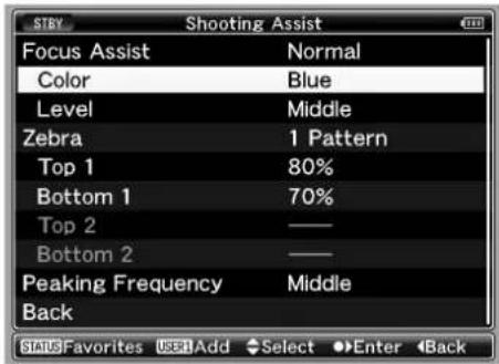
Memo:
- Adding items to [Favorites Menu] cannot be performed in the following cases. [USER1 Add] is displayed in gray in the operation guide.
- Selected item is already added to [Favorites Menu].
●Number of menu items that can be added (20 items) is exceeded.
3 Press the [USER1] button.
A screen to confirm the add appears.
4 Select [Add] and press the Set button (●).
The selected menu item is added to [Favorites Menu].

Memo:
- Long descriptive names may be displayed for the menu items in [Favorites Menu] to enable better understanding.
Editing [Favorites Menu]
You can delete or change the order of the items added to [Favorites Menu].
■Deleting Items from [Favorites Menu]
1 Open the [Favorites Menu] screen.
①Press the [MENU] button to open the [Main Menu] screen.
②Press the [STATUS] button to open the [Favorites Menu] screen.
2 Select [Edit Favorites] and press the Set button (●) or crossed-shaped button (▶).
The header turns magenta and the editing mode is activated.

3 Select the menu or submenu item to delete.

4 Press the [USER2] button.
[Delete Mark] (✗ appears at the beginning of the item.
Delete Mark

Memo:
- When the [USER2] button is pressed again while the menu item with [Delete Mark] ( ✗ selected, [Delete Mark] ( ✗ suggests.
5 Press the [USER1] button.
The option menu to exit the [Favorites Menu] editing mode appears.
6 Select [Save & Exit] and press the Set button (●).
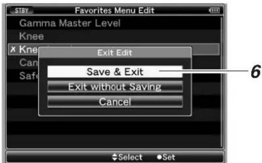
Memo:
- Deletion is not complete until the changes are saved with [Save & Exit].
- To exit the editing mode without deleting any items, select [Exit without Saving].
●To return to the editing mode, select [Cancel].
Adding/Editing Frequently Used Menu Items (Favorites Menu) (continued)
Editing [Favorites Menu] (continued)
■Changing the Order of Items in [Favorites Menu]
![[MENU] Button Set Button (●) TC 174 1/4 OFF [CANCEL] Button [STATUS] Button Cross-shaped button (▲▼▲▼) [USER1] Button [USER2] Button](/content/2026/06/1254269/images/f7c69122987b6ef85bfdbd03048143a6d966f5a861dc3f51a0eab5d1b0ee0afb.jpg)
1 Open the [Favorites Menu] screen.
①Press the [MENU] button to open the [Main Menu] screen.
②Press the [STATUS] button to open the [Favorites Menu] screen.
2 Select [Edit Favorites] and press the Set button (●) or crossed-shaped button (▶).
The header turns magenta and the editing mode is activated.

3 Select the menu or submenu item to move and press the Set button (●).
The moving mode is activated and a position selection bar for the move appears.

4 Select the position to move to with the cross-shaped button (▲▼).
Move the position selection bar with the cross-shaped button (▲▼) and select a position to move to.
5 Press the Set button (●).
The selected item moves to the new position.

6 Press the [USER1] button.
The option menu to exit the [Favorites Menu] editing mode appears.
7 Select [Save & Exit] and press the Set button (●).

Memo:
- Moving is not complete until the changes are saved with [Save & Exit].
- To exit the editing mode without saving any changes, select [Exit without Saving].
●To return to the editing mode, select [Cancel].
Status Screen in Camera Mode
STATUS 0 Screen

flowchart
graph TD
    A["30/24 fps"] --> B["DD 20min"]
    B --> C{Appears only when connected to an external device}
    C --> D["MAX 123%"]
    C --> E["MIN 45%"]
    D --> F["SKIN AREA"]
    E --> G["S.DTL"]
    F --> H["B -3"]
    G --> I["A<3200K>"]
    H --> J["A 1min"]
    I --> K["A 1min"]
    L["STBY"] --> M["RES"]
    M --> N["F5.6"]
    N --> O["AE+1 9dB 1/10000"]
    O --> P["Page 96"]
    style A fill:#f9f,stroke:#333
    style B fill:#ccf,stroke:#333
    style C fill:#cfc,stroke:#333
    style D fill:#fcc,stroke:#333
    style E fill:#cff,stroke:#333
    style F fill:#ffc,stroke:#333
    style G fill:#cfc,stroke:#333
    style H fill:#fcc,stroke:#333
    style I fill:#ffc,stroke:#333
    style J fill:#fcc,stroke:#333
    style K fill:#ffc,stroke:#333
    style L fill:#fcc,stroke:#333
| Item Description | ||
| 1Media Status | ----: No card found in the selected slotSTBY: Recording standby (recording pause)REC: RecordingREVIEW: Clip Review (Page 52)STBYP: Pre Rec recording standby (Page 54)RECP: Pre Rec recording (Page 54)STBYC: Clip Continuous recording standby (Page 55) | RECC: Clip Continuous recording (Page 55)STBYC (displayed in red): Clip Continuous recording pause (Page 55)STOP: Unable to record to the card in the slotPOFF: Power OFF |
| 2Iris Status Mark | Indicates whether the brightness of the image is appropriate.▲: Iris set higher than normal●: Iris set to normal▼: Iris set lower than normal | |
| 3Iris F-Number | Displays F-number of the lens iris.This is not displayed for some lens types, and when the lens cable is disconnected.(OPEN, F2, F2.8, F4, F5.6, F8, F11, F16, CLOSE)Memo:·You can specify the type of display and whether to display the information using [F.No/Iris Indicator] of [Status Display] in the [LCD/VF] menu. (Page 84) | |
| 4AE Level | Appears when the AE function is activated and [AE LEVEL] in the [Camera Function] menu is set to a value other than “Normal”. (Page 73)(AE-3, AE-2, AE-1, AE+1, AE+2, AE+3) | |
| 5Gain | Displays the gain value when it is not “0dB”.(3dB, 6dB, 9dB, 12dB, 15dB, 18dB, ALC) | |
| 6Shutter | Displays the current shutter speed when [Shutter] in the [Camera Function] menu is set to [Step]/[Variable] and the shutter is ON. (Page 73)EEI: Displayed when [Shutter] is set to “EEI” (auto adjustment mode).FAS: Displayed when shutter or gain is set to the auto adjustment mode.Memo:·The variable range of the shutter speed varies according to the video format settings. (Page 38) | |
| 7White Balance Mode | Displays the current white balance mode.A<**00K>, B<**00K>, P<**00K>(“**00” indicates color temperature)(** of A and B : 23, 25, 28, 30, 32, 34, 37, 43, 52, 65, 80)(** of P : 32, 56)FAW: When the Fulltime Auto White balance mode is ONMANU: Manual White Balance mode (only during control using the remote control) | |
| 8Black Toe | Appears when [Black Toe] in the [Camera Process] menu is set to a value other than “Normal”.(Page 76)B+1 to B+5: Displays the “Stretch Level” when [Black Toe] is set to “Stretch” (Level 1 to Level 5)B-1 to B-5: Displays the “Compress Level” when [Black Toe] is set to “Compress” (Level 1 to Level 5)No display: When [Black Toe] is set to “Normal” | |
| 9Skin Detail Operation | Appears as “S.DTL” when the Skin Detail function is turned ON. | |
| 10Operation of Functions | SKIN AREA: Blinks when the Skin Area display is ON.FOCUS: Appears when the Focus Assist function is activated. When “ACCU-Focus” is enabled, “ACCU-FOCUS” blinks for about 10 seconds while Focus Assist starts up, after which the “FOCUS” indicator lights up. When [ACCU-Focus] is activated, it is forcibly turned OFF after recording starts. ( page 83) | |
| 11Luminance Information | Appears when the Spot Meter function is activated. For details of the display, refer to [Setting Spot Meter] ( Page 51 ).MAX: Maximum luminanceMIN: Minimum luminance | |
| 12Event/Warning Display Area | Displays the settings for about 3 seconds when the gain or shutter speed is manually changed.For other messages displayed in this area, refer to [Error Displays and Actions] ( Page 122 ). | |
| Displayed Content Setting Status | ||
| GAIN **dB (**: 0, 3, 6, 9, 12, 15, 18) | Gain value is altered | |
| GAIN ALC Gain is set to “ALC” | ||
| FULL AUTO ON, FULL AUTO OFF | [FULL AUTO] is turned “ON/OFF” | |
| ZEBRA ON, ZEBRA OFF | [Zebra] is turned “ON/OFF” | |
| FOCUS ASSIST ON, FOCUS ASSIST OFF | [Focus Assist] is turned “ON/OFF” | |
| SHUTTER **(****K : 1/6, 1/6.25, 1/7.5, 1/12, 1/12.5, 1/15, 1/24, 1/25, 1/30, 1/48, 1/50, 1/60, 1/100, 1/120, 1/250, 1/500, 1/1000, 1/2000, 1/4000, 1/10000) | Shutter speed is altered *1 | |
| V. SHUTTER **** (****: 1/24.01 to 1/1998.0) | Variable shutter speed is altered *1 | |
| SHUTTER OFF **(**** is the standard shutter value in the respective modes.) | Shutter is turned “OFF” *1 | |
| WHITE BAL * <****K>(*: A, B, PRESET)(****K : 2300, 2500, 2800, 3000, 3200, 3400, 3700, 4300, 5200, 5600, 6500, 8000) | White balance value is altered | |
| WHITE BAL FAW | FAW (Fulltime Auto White balance) is activated | |
| FILTER ****(**: OFF,1/4ND,1/16ND) | [ND FILTER] setting is altered | |
| AE LEVEL **(****: -3, -2, -1, NORMAL, +1, +2, +3) | [AE LEVEL] value is altered | |
| SPOT METER ****(****: ON, FIXED, OFF, SELECT) | Spot meter status is changed ( page 51 ) | |
| BLACK NORMAL | [Black Toe] is set to “Normal” | |
| BLACK STRETCH * (*: 1,2,3,4,5,) | [Stretch Level] of [Black Toe] is altered | |
| BLACK COMPRESS * (*: 1,2,3,4,5,) | [Compress Level] of [Black Toe] is altered | |
| WHITE BAL PRESET <3200K>, WHITE BAL PRESET <5600K> | [Preset Temp.] value is altered *2 | |
| REC SWITCH LOCKED, REC SWITCH UNLOCKED | Record button lock switch is turned ON/OFF in Camera mode, or [REC] switch on the handle of the camera recorder is pressed while being locked | |
| SLOT SWITCHED * (*: A, B) | Active SDHC slot is switched automatically or using the [SLOT SELECT] button in Camera mode. | |
| TRIGGER TO HD, TRIGGER TO DV Recording command | is sent out from the [IEEE1394] terminal | |
| FRAME RATE rrrr/pp fps(rrrr: recording frame rate, pp: playback frame rate) | Variable frame rate is adjusted using the cross-shaped button ( ▶▶) | |
| OK MARK ADDED, OK MARK DELETED | OK mark is added or deleted ( page 64 ) | |
| Other Displays ( page 122 [Error Displays and Actions]) | ||
| 13Frame Rate | Appears as xx/yy fps (xx: recording frame rate, yy: playback frame rate) only when “Variable Frame” is set in the [Rec Mode] menu. ( page 71 ) | |
* 1 : The variable range of the shutter speed varies according to the video format settings. (u 2 Page 38)
* 2 : Displayed when the [WHT.BAL] white balance selection switch is set to "PRESET".
Status Screen in Camera Mode (continued)
STATUS 1 Screen

| Item Description | ||
| 1Resolution | Displays the video image resolution.(1920×1080, 1440×1080, 1280×720) | |
| 2Frame Rate/Bit Rate | Displays the frame rate and bit rate in pairs.(60p HQ, 30p HQ, 60i HQ, 60p SP, 30p SP, 50p HQ, 25p HQ, 50i HQ, 50p SP, 25p SP, 50i SP, 24p HQ, 24p SP) | |
| 3OK Mark | Appears when an OK mark is added. (ES Page 64) | |
| 4Remaining Space on Media | Displays the remaining recording time of the SDHC cards in Slot A and Slot B separately.Memo:Only warnings are displayed in the STATUS 0 and STATUS 4 Screens. (When the total remaining time for the SDHC cards in slot A and slot B is less than 3 minutes):Currently selected slot. (White card):SDHC card requires restoring or formatting, or SDHC card is not supported (not of class 6 type):Write-protect switch of SDHC card is set. | |
| 5Voltage/Battery Power | Displays the current status of the power supply in use. | |
| Display Description | ||
| (H2SHK) 12.3V | Currently powered by an AC adapter. The current voltage is shown on the right.If the supplied voltage from the AC adapter is low, the voltage value will be displayed in red as a warning. | |
| (X23T) 12.3V(746A) 200min(2K6Z) 30%(857T) RES | Currently powered by a battery.When the battery power runs out, the battery mark appears hollow, and “RES” is displayed.The display on the right can be set using [Battery Info] of [Status Display] in the [LCD/VF] menu. (ES Page 85) | |
| 6Audio Level Meter | [AT7Y] -20 dB CH 1 (3AH5) (52KY) CH 2 (A56G) (TTHW) | Displays the audio level for CH-1 and CH-2.When [Rec Mode] in the [Rec Mode] menu is set to “Variable Frame”, audio cannot be recorded and is indicated by the Mark.The positions of -20 dB and -10 dB are displayed as “■”.Memo:You can turn ON/OFF the display using [Audio Meter] of [Status Display] in the [LCD/VF] menu. (ES Page 85) |
| Item Description | |
| 7ND Filter Position | Displays the current ND filter position.No display: [ND FILTER] is set to “OFF”ND1/4: [ND FILTER] is set to “1/4”ND1/16: [ND FILTER] is set to “1/16”Memo: ·You can turn ON/OFF the display using [Filter] of [Status Display] in the [LCD/VF] menu. (Page 84) |
| 8Remaining Space on External Device | Displays the remaining recording time of the external device (0 to 999). When the remaining time is running out, this is indicated in red (value + unit of measurement) as a warning to the user.Memo: ·Only warnings are displayed in the STATUS 0 and STATUS 4 Screens. |
| 9Operation of External Device | Displays the operating status of the connected external device. For details, refer to the instruction manual of the corresponding external device.Memo: ·Only warnings are displayed in the STATUS 0 and STATUS 4 Screens. |
| 10Time Code (TC)/User’s Bit (UB) | Displays the time code (hour:minute:second:frame) or user’s bit data.Example: Time code:   → Colon (:) for non-drop framesUser’s bit: → Colon (:) for non-drop framesUser’s bit:  Dot (.) for drop framesMemo: ·You can turn ON/OFF the display using [TC/UB] of [Status Display] in the [LCD/VF] menu.(Page 85) ·You can select whether to display the time code or user’s bit using the [TC DISPLAY] switch on the inner panel of the LCD monitor. Dot (.) for drop framesMemo: ·You can turn ON/OFF the display using [TC/UB] of [Status Display] in the [LCD/VF] menu.(Page 85) ·You can select whether to display the time code or user’s bit using the [TC DISPLAY] switch on the inner panel of the LCD monitor. |
Status Screen in Camera Mode (continued)
STATUS 2 Screen
![CAMERA INFORMATION SETUP FILE SCENE ● [ SCENE ] ZEBRA1 50%-100% ZEBRA2 70%-80% AUDIO CH1 M CH2 M FORMAT QuickTime MEDIA A125min B123min STBY 282min Jan 2. 2009 01:23:45AM * 0 * 1](/content/2026/06/1254269/images/3fd63ef52ef97fd2ef1752e938ac8001f1e0f849c9023bea8596b3187e83df86.jpg)
* 0 : Same as STATUS 0 Screen (Page 94)
* 1 : Same as STATUS 1 Screen (Page 96)
| Item Description | |
| 1Date/Time | Displays the current date and time.Note:The date/time display style can be specified at [LCD/VF]→[Status Display]→[Date Style]/[Time Style].(Page 85) |
| 2Remaining Space on MEDIA | Displays the remaining recording time of the SDHC cards in slot A and slot B separately.A Currently selected slot. (White card)A! SDHC card requires restoring or formatting, or SDHC card is not supported (not of class 6 type).A: Write-protect switch of SDHC card is set. |
| 3FORMAT | Displays the file format for recording to the SDHC card (File Format) that is specified at [File Format] in the [Record Format] menu. (Page 71) |
| 4AUDIO | Displays the status of the [AUDIO SELECT CH-1/CH-2] switch. (A: “AUTO”/M: “MANUAL”) |
| 5ZEBRA1/ZEBRA2 Values | Displays the settings from “Bottom1” to “Top1” specified at [Zebra], and the settings from “Bottom2” to “Top2” specified at [Zebra]. (Page 83)Memo:When [Zebra] in the menu is set to “1Pattern”, ZEBRA2 appears as “---”. (Page 83) |
| 6Subname of Setup File | Displays the subname of the setup file.Memo:“●” appears at the beginning when changes are made to the loaded file. (Page 111) |
| 7SETUP FILE | Displays the type of the loaded file. (SCENE/PICTURE) |
STATUS 3 Screen
This screen displays a list of the functions assigned to the switches.
![* 1 : Appears only when a warning is displayed SWITCH ASSIGN FAW NONE GAIN [ L / M / H ] 0dB / 9dB / 12dB USER 1 BARS USER 2 B.STRETCH3 USER 3 LOAD FILE RET CLIP REVIEW SKIN/SPOT SPOT METER AE LEVEL AE LEVEL/VFR STBY 282min Jan 2. 2008 01:23:45AM * 0 * 1 * 2](/content/2026/06/1254269/images/c05f39995ddce1a0ae252ef4efb813739211a163dea519d233663ae44e6a47ec.jpg)
* 0 : Same as STATUS 0 Screen (Page 94)
* 1 : Same as STATUS 1 Screen (Page 96)
* 2 : Same as STATUS 2 Screen (Page 98)
| Item Description | |
| 1[FAW] Function Assignment | Displays the position of the [WHT.BAL] selection switch that is assigned with the FAW function. (NONE, A, B, PRESET) |
| 2[GAIN] Switch Settings | Displays the setting values for each of the positions ([L]/[M]/[H]) on the [GAIN] switch. (0dB, 3dB, 6dB, 9dB, 12dB, 15dB, 18dB, AGC) |
| 3[USER1,USER2,USER3] Button Function Settings | Displays the setting status of the [USER1], [USER2], and [USER3] buttons. (NONE, BARS, PRESET TEMP., B.STRETCH*, B.COMPRESS*, RET, LOAD FILE) * indicates 1 to 5 |
| 4[RET] Button Function Settings | Displays the setting status of the [RET] button on the lens. (CLIP REVIEW, FOCUS ASSIST, OK MARK) |
| 5[SKIN AREA/SPOT METER] Switch Settings | Displays the setting status of the [SKIN AREA/SPOT METER] switch. (SKIN AREA, SPOT METER) |
| 6 Cross-Shaped Button (◀▶) Function Assignment | Displays the functions assigned to the left/right (◀▶) of the cross-shaped button. (DISABLE, AE LEVEL, AE LEVEL/VFR) |
STATUS 4 Screen
This screen displays the event. It is also used to display warnings only.
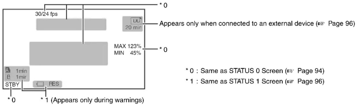
flowchart
graph TD
    A["Start"] --> B["30/24 fps"]
    B --> C["DU: 20 min"]
    C --> D["Max: 123%, MIN: 45%"]
    D --> E["* 0: Same as STATUS 0 Screen (Page 94)"]
    D --> F["* 1: Same as STATUS 1 Screen (Page 96)"]
    G["Start"] --> H["A: 1min, B: 1mir, STBY"]
    H --> I["* 0: Same as STATUS 0 Screen (Page 94)"]
    H --> J["* 1: Same as STATUS 1 Screen (Page 96)"]
    K["Start"] --> L["* 1 (Appears only during warnings)"]
    L --> M["* 0: Same as STATUS 0 Screen (Page 94)"]
    L --> N["* 1: Same as STATUS 1 Screen (Page 96)"]
Status Screen in SD Card Mode
These are the status screens displayed in Media mode (SD Card mode, Media mode).
STATUS 0 Screen
This screen displays the media status or event. It is also used to display warnings only.
STATUS 1 and STATUS 2 Screens

STATUS 1 Screen STATUS 2 Screen

| Item Description | |
| 1OK Mark | Appears when an OK mark is added. (※ Page 64) |
| 2Resolution | Displays the video image resolution.(1920×1080, 1440×1080, 1280×720) |
| 3Frame Rate/Bit Rate | Displays the frame rate and bit rate in pairs.(60p HQ, 30p HQ, 60i HQ, 60p SP, 30p SP, 60i SP, 50p HQ, 25p HQ, 50i HQ, 50p SP, 25p SP, 50i SP, 24p HQ, 24p SP) |
| 4Media | Displays the media slot (A or B) of the currently played clip.A key mark appears when the write-protect switch of the SDHC card is set. |
| 5Clip Information | Displays current clip number/total number of clips. |
| 6Time Code (TC)/User's Bit (UB) | Displays the time code (hour:minute:second:frame) or user's bit data.TC : Time codeUB : User's bitThe framing mode display for the time code is as follows.00:00:00:00Colon (:) for non-drop framesDot (.) for drop framesMemo:You can turn ON/OFF the display using [TC/UB] of [Status Display] in the [LCD/VF] menu.(※Page 85)You can select whether to display the time code or user's bit using the [TC DISPLAY] switch on the inner panel of the LCD monitor. |
| Item Description | ||
| 7Date/Time | Displays the date/time that is recorded on the currently played SDHC card. Note: The date/time display style can be specified at [LCD/VF]→[Status Display]→[Date Style]/[Time Style]. (Page 85) | |
| 8Audio Level Meter | 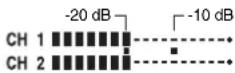 | Displays the audio level for CH-1 and CH-2.The positions of -20 dB and -10 dB are displayed as “■”. Memo: You can turn ON/OFF the display using [Audio Meter] of [Status Display] in the [LCD/VF] menu. (Page 85) |
| 9Voltage/Battery Power | Displays the current status of the power supply in use. | |
| Display Description | ||
| 12.3V | Currently powered by an AC adapter. The current voltage is shown on the right. If the supplied voltage from the AC adapter is low, the voltage value will be displayed in red as a warning. | |
| 12.3V200min30%RES | Currently powered by a battery.When the battery power runs out, the battery mark appears hollow, and “RES” is displayed.Memo: The display on the right can be set using [Battery Info] of [Status Display] in the [LCD/VF] menu. (Page 85) | |
| 10Media Status | PLAY : Playing STILL : Still picture playback mode FWD * : High-speed playback in the forward direction (* playback speed: 5x or 15x) REV * : High-speed playback in the reverse direction (* reverse playback speed: 5x or 15x) STOP : Stop mode POFF : Power OFF | |
| 11Operation Guide | Displays a guide for the current operation buttons. | |
Status Screen in IEEE1394 Input Mode
These are the status screens displayed in Media mode (IEEE1394 Input mode).
STATUS 1 Screen
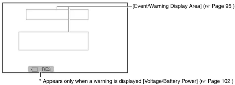
flowchart
graph TD
    A["Event/Warning Display Area"] --> B["Block 1"]
    A --> C["Block 2"]
    D["RES"] --> E["Block 3"]
    F["* Appears only when a warning is displayed [Voltage/Battery Power"] (Page 102)] --> G["Block 4"]
STATUS 2 Screen
![[Event/Warning Display Area] (ns Page 95 ) 1280x720 24p HQ CH 1 CH 2 282min ④ ③](/content/2026/06/1254269/images/9da70faa6f4d4cb2c2b24f8fd471e93126a3fde2badc3caee8b70192c67e6daa.jpg)
| Item Description | ||
| 1Frame Rate/Bit Rate | Displays the frame rate and bit rate in pairs. (60p HQ, 30p HQ, 60i HQ, 60p SP, 30p SP, 60i SP, 50p HQ, 25p HQ, 50i HQ, 50p SP, 25p SP, 50i SP, 24p HQ, 24p SP) | |
| 2Resolution | Displays the video image resolution. (1920×1080, 1440×1080, 1280×720) | |
| 3Audio Level Meter | Displays the audio level for CH-1 and CH-2.When the input sampling frequency is set to a value other than 48K in IEEE1394 mode, a Ⓧ mark is displayed with the frequency. (32k, 44.1k)The positions of -20 dB and -10 dB are displayed as “■”.Memo:●You can turn ON/OFF the display using [Audio Meter] of [Status Display] in the [LCD/VF] menu. (e x Page 85) | |
| 4Voltage/Battery Power | Displays the current status of the power supply in use. | |
| Display Descript | on | |
| 12.3V | Currently powered by an AC adapter. The current voltage is shown on the right.If the supplied voltage from the AC adapter is low, the voltage value will be displayed in red as a warning. | |
| 12.3V200min30%RES | Currently powered by a battery.When the battery power runs out, the battery mark appears hollow, and “RES” is displayed.Memo:●The display on the right can be set using [Battery Info] of [Status Display] in the [LCD/VF] menu. (e x Page 85) | |
Enlarged Status Display on LCD Monitor
You can enlarge and display only the characters of the status screen on the LCD monitor.
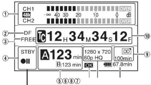

| Item Description | ||
| 1Audio Level Meter | Displays the audio levels of [CH-1] and [CH-2].If the reference audio level (“-20dB” or “-12dB”) is exceeded, this is displayed in yellow. The “Over” area is displayed in red. “48k” is the sampling frequency.Memo:When [Rec Mode] in the [Rec Mode] menu is set to “Variable Frame”, audio cannot be recorded and is indicated by the mark. | |
| 2Framing Mode | Displays the framing mode.[DF]: Drop frame[NDF]: Non-drop frame | |
| 3Time Code Generator | Displays the operation mode of the time code. (Display: [FREE], [RECR], [REGN]) (Page 46) | |
| 4Media Status | Displays the SDHC card status in characters and symbols. | |
| ----: No card found in the selected slotSTBY: Recording standby (recording pause)REC: RecordingREVIEW: Clip Review (Page 52)STBYP: Pre Rec recording standby (Page 54)RECP: Pre Rec recording (Page 54)STBYC: Clip Continuous recording standby (Page 55) | RECC: Clip Continuous recording (Page 55)STBYC (displayed in red): Clip Continuous recording pause (Page 55)STOP: Unable to record to the card in the slotPOFF: Power OFF | |
| 5Remaining Space on Media | Displays the remaining recording time on the SDHC card. The currently active slot is indicated with an enlarged black card icon with white letters. A key mark appears when the write-protect switch of the SDHC card is set. | |
| 6OK Mark | Appears as [OK] when the currently played clip is appended with an OK mark. | |
| 7Video Format | Displays the video format that is set. (Page 36) | |
| 8Voltage/Battery Power | Displays the current status of the power supply in use. | |
| Display | Description | |
| 12.3V | Currently powered by an AC adapter. The current voltage is shown on the right.If the supplied voltage from the AC adapter is low, the voltage value will be displayed in red as a warning. | |
| 12.3V200min30%RES | Currently powered by a battery.When the battery power runs out, the battery mark appears hollow, and “RES” is displayed.Memo:The display on the right can be set using [Battery Info] of [Status Display] in the [LCD/VF] menu. (Page 85) | |
| 9Operation of External Device | Displays the operating status of the connected external device.For details, refer to the instruction manual of the corresponding external device. | |
| 10Time Code (TC)/User’s Bit (UB) | Displays the time code (hour:minute:second:frame) or user’s bit data.00:00:000Colon :) for non-drop framesDot :) for drop frames | |
Memo:
- During enlarged display of the status on the LCD monitor screen, the video image remains displayed on the viewfinder.
Marker and Safety Zone Displays (Camera Mode Only)
The marker and safety zone displays are useful in helping you determine the angle of view for the image according to the shooting purpose.
Example of display when [Aspect Ratio] = "4:3", [Aspect Marker] = "Line+Halftone", and [Center Mark] = "On"

You can turn ON/OFF the safety zone and center mark displays as shown below using the [Aspect Ratio], [Safety Zone] and [Center Mark] settings of [Marker Setting] in the [LCD/VF] menu. (Page 84)
[Aspect Marker] Display
■ When [Aspect Ratio] = "4:3"
| [Line] [Halftone] [Line+Halftone] | ||
![JVC GY-HM700U - [Aspect Marker] Display - 1](/content/2026/06/1254269/images/8dc5b1a92a7ffb03d56a6afc4f95c8d5e29c4dbd56b3cebea7c7e77816f2a108.jpg) | ![JVC GY-HM700U - [Aspect Marker] Display - 2](/content/2026/06/1254269/images/baf0322e1a3665b5801f7a5bd57626c3f610254794fee0072c1c47c772d5478b.jpg) | ![JVC GY-HM700U - [Aspect Marker] Display - 3](/content/2026/06/1254269/images/3f21cc27b3d0f20b2d355a61346cce9957cf0bf3803a8f012805efd091e3cd69.jpg) |
[Aspect Marker] Display for Different [Aspect Ratio] Settings
■ When [Aspect Marker] = "Halftone"
| [4:3] | [14:9] | [16:9]/[16:9(+4:3)] | [2.35:1 Center] | [2.35:1C.HeadRM] |
![JVC GY-HM700U - [Aspect Marker] Display for Different [Aspect Ratio] Settings - 1](/content/2026/06/1254269/images/dd42d0b34cb6ab99e2ea77910f127d8014648ed67e9580d4ed6c90c543164271.jpg) | ![JVC GY-HM700U - [Aspect Marker] Display for Different [Aspect Ratio] Settings - 2](/content/2026/06/1254269/images/8012351ac11cb8acead3a9ce36bcff7d9cbc80f2345e24f7a842c3a524b7223b.jpg) | ![JVC GY-HM700U - [Aspect Marker] Display for Different [Aspect Ratio] Settings - 3](/content/2026/06/1254269/images/885d6da3a3b971366768739c7f4946c75c15eecd81a0ee4c8dd5025d0baeb9e6.jpg) * [Aspect Marker] cannot be set. (Fixed at “Off”) * [Aspect Marker] cannot be set. (Fixed at “Off”) | ![JVC GY-HM700U - [Aspect Marker] Display for Different [Aspect Ratio] Settings - 4](/content/2026/06/1254269/images/6005b11ce61416f8b77464ac2717bc98d9d74f052cfad24f08f86da02c5d58e8.jpg) | ![JVC GY-HM700U - [Aspect Marker] Display for Different [Aspect Ratio] Settings - 5](/content/2026/06/1254269/images/8ed6d7ee958ff5b933864482199c301a912a08476b2144845102c3a5ef305485.jpg) |
| [1.85:1 Center] | [1.85:1C.HeadRM] | [1.66:1] | [1.75:1] | |
![JVC GY-HM700U - [Aspect Marker] Display for Different [Aspect Ratio] Settings - 6](/content/2026/06/1254269/images/348149c041f2b00808a8c69d6c2b7dd14dea13d5d643e8f538b6081c982e458e.jpg) | ![JVC GY-HM700U - [Aspect Marker] Display for Different [Aspect Ratio] Settings - 7](/content/2026/06/1254269/images/c1a349554665af1e87e623367f43560237fa4938ef1e61ecaa7e725da389a9aa.jpg) | ![JVC GY-HM700U - [Aspect Marker] Display for Different [Aspect Ratio] Settings - 8](/content/2026/06/1254269/images/da02c492473525de58a5fbaeb844c06181b6b719d8e864f889da8b61ac296974.jpg) | ![JVC GY-HM700U - [Aspect Marker] Display for Different [Aspect Ratio] Settings - 9](/content/2026/06/1254269/images/183458bfa4fdda100f36f6a1728224f0856d7f2c7f02c4261736a5717b36de0f.jpg) |
[Safety Zone] Display
■ When [Aspect Ratio] = “4:3”, [Aspect Marker] = “Halftone”, and [Center Mark] = “On”
| [Off] | [95%] | [93%] | [90%] | [88%] |
![JVC GY-HM700U - [Safety Zone] Display - 1](/content/2026/06/1254269/images/fe3745bc3e29bc26ea1c97be92cfde747707bedc1820c96fe6951b28a22b00eb.jpg) | ![JVC GY-HM700U - [Safety Zone] Display - 2](/content/2026/06/1254269/images/5f2b1b067e60f22d1aabeeaa2f88cf730253eca7e854e04a32b81f8dda42e5b5.jpg) | ![JVC GY-HM700U - [Safety Zone] Display - 3](/content/2026/06/1254269/images/15705aea94ec15245ac46a42fac9e9b239628196adb211f5aa5ae14f34471b51.jpg) | ![JVC GY-HM700U - [Safety Zone] Display - 4](/content/2026/06/1254269/images/787e714b6f7c05886755e6677810ba25507f1926ca7cfea5ddefedfca5a0c937.jpg) | ![JVC GY-HM700U - [Safety Zone] Display - 5](/content/2026/06/1254269/images/30d8a454b9ed963c5f058e0a97add8607dfb5160a41b8b5ee0c624e2bc49660f.jpg) |
![JVC GY-HM700U - [Safety Zone] Display - 6](/content/2026/06/1254269/images/77200876ac80423d862612740459b1bd745919b3d9e03cc2afa63a2df552ce4b.jpg)
[Center Mark] Display
■ When [Aspect Ratio] = “4:3”, [Aspect Marker] = “Halftone”, and [Safety Zone] = “80%”
| [Off] [On] | |
![JVC GY-HM700U - [Center Mark] Display - 1](/content/2026/06/1254269/images/340e25c6d751819b4bb886b2d67e32d2afdd8c7a02a9e581fea8b3b48d505b6c.jpg) | ![JVC GY-HM700U - [Center Mark] Display - 2](/content/2026/06/1254269/images/914f14aded2212d6c55ecc3be22e9f71dc551dec6a3e77678f0023fd89e4cc42.jpg) |
When [Aspect Ratio] = “4:3”, [Aspect Marker] = “Halftone”, and [Safety Zone] = “Off”
| [Off] [On] | |||
![JVC GY-HM700U - [Center Mark] Display - 3](/content/2026/06/1254269/images/581ff6cf5326a71d13facf879391b62426a31511aad1d8c8d91880b8d5fa991c.jpg) | ![JVC GY-HM700U - [Center Mark] Display - 4](/content/2026/06/1254269/images/0af1fa89fc59f326375280d7c224f040824a86b5b64f1ae258103cbac7d86dbc.jpg) |
Smoothening the Skin Color (Skin Detail Function)
The Skin Detail function can be used to reduce the contour enhancement of video signals for only the skin areas so as to produce a smoother skin tone.
Preparations Before Using the Skin Detail Function (Skin Adjust Function)
1 Adjust the white balance. (Page 40)
2 Display the [Skin Color Adjust] screen. (Page 78)
- Select [Main Menu]→[Camera Process]→[Detail]/[Adjust]→[Skin Color Adjust], and press the Set button (●).
●The entire image switches to black-and-white display, leaving only the detected skin areas in color.

Memo:
- The displays for [Bars], [Zebra], markers ([Aspect Marker]/[Safety Zone]/[Center Mark]), [Focus Assist] mode, and [B] mode in the [VF Display] menu are temporarily turned "Off".
■Hue Range Detection
1 Project the detected object inside the skin color detection frame.
2 Place the cursor at [Skin Color Detect] with the cross-shaped button (▲▼).
3 Press the Set button (●).
Display switches from "Stop" to "Execute", and detection starts.
Memo:
- "Error" is displayed if the object inside the frame is not within the preset color range.
4 Press the Set button (●) after the desired hue range is detected.
- If no "Error" is displayed, the data is saved and the process ends.
- If "Error" appears, the process ends without saving the data.
5 Place the cursor at [Back] after the hue range is detected, and press the Set button (●).
Returns to the [Detail] menu screen.
■Color Range Setting
1 Place the cursor at [Skin Color Range] with the cross-shaped button (▲▼).
2 Press the Set button (●) or cross-shaped button (▶) to move the cursor to a setting value.

3 Select a setting value using the cross-shaped button (▲▼), and press the Set button (●).
Select a setting within the [Narrow, -1 to -9, Normal, 9 to 1, Wide] range.
4 Place the cursor at [Back] after setting is complete, and press the Set button (●).
The data is saved, and the screen returns to the [Detail] menu.
Using the Skin Detail Function
1 Set [Skin Detect] to "On". (Page 78)
- Select [Main Menu]→[Camera Process]→[Detail]/[Adjust]→[Skin Detect] and set to "On".
- "S.DTL" appears on the STATUS 0 and 1 Screens of the LCD monitor and viewfinder when the Skin Detail function is activated.
"S.DTL" appears

STATUS 1 Screen
2 Set the adjustment level for the contour enhancement of the skin tone. (Page 78)
Set using [Main Menu]→[Camera Process]→[Detail]/[Adjust]→[Skin Color Detect]/[Level].
Checking the Preset Hue Area
1 Set the [ZEBRA ON/OFF] switch at the front of the camera recorder to the [SKIN AREA/SPOT METER] end.
Doing so forcibly turns ON the Skin Adjust function temporarily, and the preset hue area is displayed in color on the LCD monitor and viewfinder.

Memo:
- When [Color Gain] in the [Camera Process] menu is set to "Off", only the area where Skin Detail is functioning is displayed in skin tone. (e) Page 77)
- When [SKIN A./SPOT M.] of [Switch Set] in the [Camera Function] menu screen is set to "Spot Meter", the hue area cannot be checked using the [SKIN AREA/SPOT METER] switch. (Page 75)
Color Bar Output
Multi-format color bars can be output on this camera recorder.
![[USER1,USER2,USER3] Buttons [FULL AUTO] Switch](/content/2026/06/1254269/images/387e49fa21f6703d72d89dc15d6bf36529c19c3bca1cd1ac364eeb782f75712e.jpg)
Setting
To output color bars, follow the setting procedure below.
1 Set the [FULL AUTO] switch to "OFF".
2 Set [Bars] in the [Camera Function] menu to "On". (Page 73).
Color bars are output.
Color Bar Output Using the USER Buttons
1 Set the [FULL AUTO] switch to "OFF".
2 Assign "Bars" to any one of the [USER1]/[USER2]/[USER3] buttons.
Set using [USER1]/[USER2]/[USER3] of [Switch Set] in the [Camera Function] menu. ( Page 74)
3 Press the corresponding [USER1]/[USER2]/[USER3] button that is assigned with "Bars".
Color bars are output.
Memo:
- During color bar output, you can select whether to output the reference audio signals using [Test Tone] in the [Audio Set] menu. (Page 72)
- Color bars are not output when the [FULL AUTO] switch is set to "ON" but [Bars] in the [FULL AUTO] menu is set to "Off". They are also not output in Media mode.
Color Matrix Adjustment
The color matrix of the camera recorder can be adjusted to a color of the user's preference.
When shooting is performed using multiple cameras, the colors of the different cameras can be adjusted, and a color of the user's preference can be set on this camera recorder. 13 saturation parameters and 3 hue parameters are available for adjustment. Adjust the color on the vector scope and waveform monitor using the color chart.
* The adjusted values of “Standard”, “Cinema Vivid”, and “Cinema Subdued” in [Color Matrix] can be stored individually. (Page 77)
1 Select [Color Matrix] or [Adjust] in the [Camera Process] menu. (E8 Page 80)
2 Adjust the saturation.
- Use the cross-shaped button ( ▲▼) to select a value. - The correction range (gray area in the chart below) for each of the 12 levels from [Mg&R Mg Level] to [B&Mg Mg Level] changes in the direction indicated by the arrow on the vector scope.

Memo:
- In addition to the vector, the luminance Y level of the correction range changes as well.
Mg&R Mg Level Increase the value:  | Corrected Y decreases Decrease the value: Corrected Y increases | |
Mg&R R Level Increase the value:  | Corrected Y increases Decrease the value: Corrected Y decreases | |
R&YI R Level Increase the value:  | Corrected Y increases Decrease the value: Corrected Y decreases | |
R&YI YI Level Increase the value:  | Corrected Y decreases Decrease the value: Corrected Y increases | |
YI&G YI Level Increase the value:  | Corrected Y decreases Decrease the value: Corrected Y increases | |
YI&G G Level Increase the value: 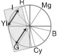 | Corrected Y increases Decrease the value: Corrected Y decreases | |
G&Cy G Level Increase the value: 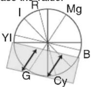 | Corrected Y increases Decrease the value: Corrected Y decreases | |
G&Cy Cy Level Increase the value:  | Corrected Y decreases Decrease the value: Corrected Y increases | |
| Cy&B Cy Level |  | Increase the value: Corrected Y decreases Decrease the value: Corrected Y increases |
Cy&B B Level Increase the value:  | Corrected Y increases Decrease the value: Corrected Y decreases | |
B&Mg B Level Increase the_value: 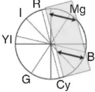 | Corrected Y increases Decrease the value: Corrected Y decreases | |
B&Mg Mg Level Increase the value:  | Corrected Y decreases Decrease the value: Corrected Y increases | |
3 Adjust YI&G Mask Range.
Adjusting [YI&G YI Level] and [YI&G G Level] may also affect the I-axis (color close to the skin tone). When [YI&G YI Level] is increased, the skin tone becomes slightly more yellowish. On the other hand, when [YI&G G Level] is increased, the skin tone becomes slightly more greenish.
Adjust [YI&G Mask Range] if you want to increase YI&G toward yellow and green without affecting the skin tone. As illustrated in the chart below, [YI&G Mask Range] adjusts the gray area from the R-axis, which disables the [YI&G YI Level] and [YI&G G Level] adjustments.
Increasing the [YI&G Mask Range] value widens the masking range. By doing so, the effect on the I-axis (color close to the skin tone) due to adjustments of [YI&G YI Level] and [YI&G G Level] is reduced. However, this also reduces the amount of correction by [YI&G YI Level] and [YI&G G Level].
| YI&G Mask Range |  |
| [YI&G YI Level] and [YI&G G Level] adjustment |
4 Adjust the hue.
Adjust the hue based on the R-, G-, and B-axes. As illustrated in the chart below, increasing the value rotates the hue in the anti-clockwise direction on the vector scope, with the respective axes as the center. Decreasing the value rotates the hue in the clockwise direction.
R Rotation Increase the value:  | Hue rotates in the anti-clockwise direction with R-axis as the center. | |
G Rotation Increase the value: 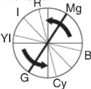 | Hue rotates in the anti-clockwise direction with G-axis as the center. | |
B Rotation Increase the value:  | Hue rotates in the anti-clockwise direction with B-axis as the center. | |
Reproduction of Dark Areas (Black Stretch/Compress Function)
Process the dark areas according to the balance of bright and dark areas in the image to adjust the overall balance of contrast.
1 Adjust [Black Toe] in the [Camera Process] menu according to the captured video signals.
2 Set the luminance point (Point Level) for "Stretch" or "Compress".
- Decide the luminance point (Point Level) at which the dark areas in the image are to be stretched or compressed.
- The luminance point (Point Level) can be set within the range of “5% to 15%”.
3 Adjust the amount of "Stretch" or "Compress".
- Set the amount to stretch or compress the dark areas in the image using [Stretch Level] or [Compress Level].
●The amount of stretch or compression increases when a larger value is specified.
Example
To increase the area of 10 % level (Point A in the figure below) in the image under normal condition ([Black Toe] is "Normal")
① Set [Black Toe] to "Stretch".
② Set [Point Level] to “10%”.
③Set the amount to increase using [Stretch Level] ("Level 1 to Level 5").
The reproduction of dark areas improves as the 10 % level point A stretches toward point B. (See figure below)

line
| Input | OUTPUT | Condition | |-------|--------|------------------------| | 0 | 0 | When [Black Toe] is "Stretch" | | 10% | 10% | Increasing the "10%" area | | 15% | 10% | [Point Level] set at "10%" |Configuring Setup Files
The menu settings can be stored on the camera recorder or an SDHC card by saving them as a setup file. Loading a saved setup file enables you to reproduce the appropriate setup state speedily. Two types of setup files are available.
■Scene file:
File that contains all menu settings, ranging from video format settings to image creation settings such as device settings and shooting conditions, as well as the contents of the [Favorites Menu].
■Picture file:
File that contains image creation settings in accordance to the shooting conditions ([Camera Process] menu items). (Page 76)
Make use of the [Setup File Manage] menu to save or load a setup file. The following operations can be performed on the [Setup File Manage] menu.
● Saving setup files (Page 112)
- Loading a setup file (Page 113)
- Resetting a saved file (Page 113)
■Number of storable setup files
Camera recorder : [CAM1] to [CAM4]
SDHC Card
Slot A : A[EXT1] to A[EXT8]
Slot B : B[EXT1] to B[EXT8]
■Preset setup files
As described below, there are three types of scene files and two types of picture files that can be loaded according to different shooting conditions.
Scene file
[GY-HD 60p LIKE] : Setting is adjusted according to the tone of the GY-HD series. [Camera Resolution] is set to "1280x720", and [Frame & Bit Rate] is set to "60p(HQ)".
[GY-HD 50p LIKE] : Setting is adjusted according to the tone of the GY-HD series. [Camera Resolution] is set to “1280x720”, and [Frame & Bit Rate] is set to “50p(HQ)”.
[CINEMA 1080/24p]: Setting that is suited for movie-like video shooting. [Camera Resolution] is set to “1920x1080”, and [Frame & Bit Rate] is set to “24p(HQ)”.
Picture file
[GY-HD LIKE] : Setting is adjusted according to the tone of the GY-HD series.
[CINEMA] : Setting that is suited for movie-like video shooting.
Memo:
●The above setup files are used exclusively for loading. They cannot be overwritten or reset.
Configuring Setup Files (continued)
Saving Setup Files
1 Display the [Setup File Manage] menu.
Select the [Setup File Manage] menu on the [Main Menu]
screen, and press the Set button (●). (Page 89)
2 Select [Store File] and press the Set button (●).
3 Select [Scene File] or [Picture File], and press the Set button (●).
The existing files are displayed.
4 Select the file to be newly saved (or overwritten) using the cross-shaped button (▲▼), and press the Set button (●).

[Store File] Menu Screen
Memo:
- Files cannot be written in the following cases. (Displayed in gray, selection disabled)
- The inserted SDHC card is not supported (those other than SDHC Class 6 cards, or unformatted cards). (File name appears as “---”.)
- Write-protect switch of the inserted SDHC card is set. (A park appears beside the SDHC card icon.)
5 Name the file.
Enter the subname using the software keyboard.
■ Operating instructions of software keyboard (Page 67)

Memo:
- When overwriting an existing file, the subname of the existing file is displayed.
- Select [Cancel] and press the Set button ( ●), or press the [CANCEL] button to return to the previous screen.
| Name Description | |
| 1Character Entry Field | Field for entering the title. You can enter up to 8 characters for the [Scene File]/[Picture File] subname. |
| 2Character Cursor | Select a character using the key cursor 4, and press the Set button (●) to input the selected character at the position of the character cursor. The character cursor moves to the next position on the right each time a character is input. The cursor can be moved using the arrow keys 6. |
| 3Character Keys | Use the cross-shaped button (▲▼◀ ▶) to move the key cursor 4 to the character you want to enter. |
| 4Key Cursor | Indicates the currently selected character or item. Use the cross-shaped button (▲▼◀ ▶) to move the cursor. |
| 5Confirmation Buttons | Select [Store] and press the Set button (●) to confirm the title. Select [Cancel] and press the Set button (●) to abort character input and return to the previous screen. |
| 6Arrow Keys | Moves the position of the character cursor 2. |
| 7[BS] Backspace Key | Select [BS] and press the Set button (●) to delete the character on the left of the character cursor 2. |
| 8[SP] Space Key | Select [SP] and press the Set button (●) to enter a space at the current position of the character cursor 2. |
6 Select [Store] from the confirmation buttons ⑤, and press the Set button (●).
A confirmation screen appears.
7 Select [Store] on the confirmation screen, and press the Set button (●).
Saving starts, and "Storing..." appears on the screen.

Memo:
- If you do not want to save the file, select [Cancel] or press the [CANCEL] button to return to the previous screen.
- When saving of a file fails, a "Store Error!" message (indicated in red frame) appears for several seconds, after which the previous screen is displayed.
8 Saving is complete.
After saving of the file is complete, "Complete" appears on the screen, and the menu screen closes automatically.
Loading a Setup File
1 Display the [Setup File Manage] menu.
Select the [Setup File Manage] menu on the [Main Menu] screen, and press the Set button (●). (Page 89)
2 Select [Load File] and press the Set button (●).
3 Select [Scene File] or [Picture File], and press the Set button (●).
The existing files are displayed.
4 Select the file to load using the cross-shaped button (▲▼), and press the Set button (●).
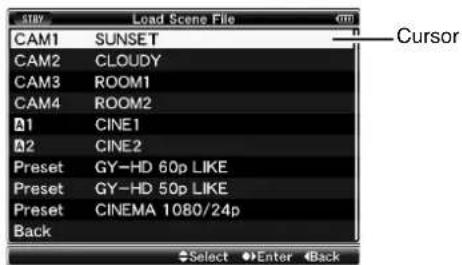
[Load File] Menu Screen
Memo:
- When the write-protect switch of the inserted SDHC card is set, a park appears beside the SDHC card icon. Setup files can be loaded from an SDHC card even if the write-protect switch is set.
5 Select [Load] on the confirmation screen, and press the Set button (●).
Loading starts, and "Loading..." appears on the screen.

Memo:
- If you do not want to load the file, select [Cancel] or press the [CANCEL] button to return to the previous screen.
- When loading of a file fails, a "Load Error!" message (indicated in red frame) appears for several seconds, after which the previous screen is displayed.
6 Loading is complete.
After loading of the file is complete, "Complete" appears on the screen, and the menu screen closes automatically.
Resetting Setup Files
1 Display the [Setup File Manage] menu.
Select the [Setup File Manage] menu on the [Main Menu] screen, and press the Set button (●). (Page 89)
2 Select [Reset File] and press the Set button (●).
3 Select [Scene File] or [Picture File], and press the Set button (●).
The existing files are displayed.
4 Select the file to delete using the cross-shaped button (▲▼), and press the Set button (●).
Memo:
- Scene files and preset scene files stored inside the SDHC card cannot be selected or reset.
5 Select [Reset] on the confirmation screen, and press the Set button (●).
Deletion starts, and "Resetting..." appears on the screen.
Memo:
- If you do not want to reset the file, select [Cancel] or press the [CANCEL] button to return to the previous screen.
6 Resetting is complete.
After resetting of the file is complete, "Complete" appears on the screen, and the menu screen closes automatically.
Connecting an External Monitor
To output live or playback video images and audio sound to an external monitor, select the output signals from the camera recorder, and connect using an appropriate cable according to the monitor to be used.
Connecting via Composite/Component Output
Either component or composite signals can be output from the BNC terminals on the terminal area of the camera recorder.
Connect the external monitor to the [Y/VIDEO] output terminal for composite signals, or to [Y/VIDEO], [PB], and [PR] video signal output terminals for component signals.
* Select the output signal using [Output Terminal] in the [A/V Out] menu. (Page 86)
* To display menu screens or status screens on the external monitor, set [Analog Out Char.] in the [A/V Out] menu to "On". (C) Page 86)

flowchart
graph TD
    A["Video IN"] --> B["Composite Output"]
    C["VIDEO OUT"] --> D["Component Output"]
    E["Computer Monitor"] --> F["Audio IN"]
    B --> G["[Y/VIDEO"] V/DIVEO["F8"], [F9]]
    D --> H["COMPONENT IN"]
    G --> I["[AUDIO OUTPUT"]]
■Settings for Composite Output
1 Down convert the signals.
You can select the method to "down convert" HD video images to SD images during composite output. Set using [Down Convert] in the [A/V Out] menu. The available modes include "Side Cut", "Letter Box" (blackened at the top and bottom), and "Squeeze" (full size, compressed at the left and right). (Page 86)
2 Add setup signals.
Setup signals can be added to the output video signals during composite output.
* You can select whether to add setup signals using [Set Up] in the [A/V Out] menu. (Page 86)
Connecting via SDI
Either HD-SDI or SD-SDI signals can be output from the [HD/SD-SDI] terminal (BNC) on the terminal area of the camera recorder.
●Digital audio signals, together with embedded (superimposed) audio signals and time code signals, are output for both the HD-SDI and SD-SDI signals.
- User's bit output from the [HD/SD-SDI] output terminal is used as a flag to determine valid video signals. Therefore, accurate values will not be output.
Memo:
- The sampling frequency for embedded (superimposed) audio signals is 48 kHz. Time code of the built-in time generator as well as playback time code are also output.
* Select the output signal using [HD/SD-SDI Out] in the [A/V Out] menu. (Page 86)
* To display menu screens or status screens on the external monitor, set [SDI Out Char.] in the [A/V Out] menu to "On". (Page 86)
![1/2000 Pq H1 [HD/SD-SDI] C=1 AUDIO OUTPUT CH=2 [HD/SD-SDI] SDI IN](/content/2026/06/1254269/images/ec6b0eb68b4eda3446883e50aac4d17d1e6a36e77b8f8e6f161816954fac6dac.jpg)
■Settings for SDI Output
1 Down convert the signals.
You can select the method to "down convert" HD video images to SD images during SD-SDI output. Set using [Down Convert] in the [A/V Out] menu. The available modes include "Side Cut", "Letter Box" (blackened at the top and bottom), and "Squeeze" (full size, compressed at the left and right). (Page 86)
[PHONES] Terminal
Audio output from the [PHONES] terminal can be selected using [Audio Monitor] in the [A/V Out] menu (Page 87) as well as the [MONITOR SELECT] switch on the camera recorder.
The different combinations of settings that are output from the [PHONES] terminal and monitor speaker are as follows.
| [MONITOR SELECT]Switch Settings | [Audio Monitor]Settings | [PHONES] Terminal | |
| L | R | ||
| [CH-1] —CH1 | |||
| [BOTH] [Mix] CH1+CH2 | |||
| [Stereo] CH1 | CH2 | ||
| [CH-2] —CH2 | |||
IEEE1394 Connection
Connecting an external device to the IEEE1394 terminal enables you to perform the following.
① Backup recording (Page 116)
The images recorded on the SDHC card in the camera recorder can be backed up.
②Stream transmission to a non-linear editing system (v 2 Page 117)
Playback images on the camera recorder can be stream output during editing using a non-linear editing system.
![[HD/DV] IEEE 1394 Terminal Mode Switch [IEEE1394] Terminal](/content/2026/06/1254269/images/916aaa8680ec5118db259fd306098f524d026017ecfe8b7e0702c6b1353ba622.jpg)
Note:
- When connecting the camera recorder to an external device using an IEEE1394 cable, make sure to observe the following. Improper connection may cause the circuit of the connected unit to malfunction.
- Turn off the power of the camera recorder and connected devices before connecting the IEEE1394 cable.
- Do not connect the cable in an environment where static electricity occurs or is likely to occur.
●Make sure that each camera recorder is connected to only one external device at any one time. - Turn off the power of the camera recorder and connected devices before switching the [HD/DV] IEEE1394 terminal mode switch.
- A message indicating "VIDEO FORMAT INCORRECT" appears if the format of the input/output video signals from the [IEEE1394] input terminal is different from the [HD/DV] IEEE1394 terminal mode switch setting. Adjust the [HD/ DV] IEEE394 terminal mode switch according to the video format.
VIDEO FORMAT INCORRECT
- If the [INT/EXT] IEEE1394 interface terminal switch is set at "EXT" and the "HQ" mode is selected in [Frame & Bit Rate], signals will not be output from the [IEEE1394] terminal. (Page 71)
IEEE1394 Connection (continued)
Backup Recording
When the camera recorder is set to Camera mode, images shot using it can be stream output from the IEEE1394 terminal.
According to the recording operation on the camera recorder, recording to the camera recorder and external device may be performed synchronously or separately.
1 Connect the camera recorder to the backup device.
Connect the camera recorder to the backup device using an IEEE1394 cable, using the camera recorder as the master device.
![Camera recorder (Master Device) [HD/DV] IEEE 1394 Terminal Mode Switch [INT/EXT] IEEE1394 Interface Terminal Switch [IEEE1394] Terminal Backup Device Cable Signal Flow](/content/2026/06/1254269/images/5088dbcb05fc86958898214f075d81fa848d74e31f76acbe424f46881a08a473.jpg)
2 Set the camera recorder to Camera mode.
3 Set the recording video format.
Note:
- Make sure that the SP mode is selected for the [Frame & Bit Rate] setting.
4 Perform the following settings on the camera recorder (master device).
① Set the [HD/DV] IEEE1394 terminal mode switch.
[DV] : During backup in the DV format
[HD] : During backup in the HD format
② Set the [INT/EXT] IEEE1394 interface terminal switch to "EXT".
③Switch to Camera mode.
④Specify how recording to the camera recorder and external device is to be performed with the recording operation on the camera recorder using [1394 Rec Trigger] in the [Others] menu. (r ® Page 88)
5 Set the external device to a mode that enables recording.
For setting and operation of external devices, refer to the instruction manual of the respective devices.
Note:
- Adjust the camera recorder and external device to the same IEEE1394 settings.
- Start recording only after ensuring that the devices are properly connected.
6 Perform recording using the camera recorder.
If the settings in 3 are appropriate, video images will be recorded to the camera recorder and external device.
Note:
●Images, audio and time code at the points where recording starts and ends may be out of sync depending on the camera recorder and backup device in use.
Memo:
- When backup recording starts, a "TRIGGER TO DV" or "TRIGGER TO HD" message appears on the LCD monitor and viewfinder for about 3 seconds.
■ Checking Videos Recorded on the External Device
(IEEE1394 Input mode of Media mode)
When images are displayed in thumbnails in Media mode (SD Card mode) and power of the device connected to the [IEEE1394] terminal is turned on, pressing the [CAM/MEDIA] selection button displays the playback images of the connected device on the LCD monitor and viewfinder. Pressing the same button has no effect if the [IEEE1394] connection is not recognized, such as when the power of the device connected to the [IEEE1394] terminal is turned off. Refer to [Status Screen in IEEE1394 Input Mode] ( uF Page 102) for the status display of this mode.
1 Press the [CAM/MEDIA] button to set to the IEEE1394 Input mode.
2 Set the external device to the playback mode.
Video images recorded on the external device are displayed on the LCD monitor and viewfinder.
Note:
- This mode is used for viewing images input to the [IEEE1394] terminal from an external device, and not intended for recording input images on the camera recorder.
Stream Transmission to a Non-linear Editing System
Playback images on the camera recorder can be stream output during editing using a non-linear editing system.
■Loading to a Non-linear Editing System in Play Mode
1 Perform the following settings on the camera recorder.
① Set the [HD/DV] IEEE1394 terminal mode switch to "DV".
② Set the [INT/EXT] IEEE1394 interface terminal switch to "EXT".
Memo:
- Stream transmission is only possible for DV format images.
2 Connect the IEEE1394 cable.
3 Turn on the power of both the camera recorder and non-linear editing system.
4 Set the camera recorder to Media mode.
Press the [CAM/MEDIA] selection button to switch to Media mode. (Page 7)
![[HD/DV] IEEE 1394 Terminal Mode Switch [INT/EXT] IEEE1394 Interface Terminal Switch DV HD INT EXT [IEEE1394] Terminal Cable [IEEE1394] Signal Flow PC](/content/2026/06/1254269/images/8c1ce551e2681d52716c19fa5441ea433fa1a8d95cf6779e75146cc7d0fca50a.jpg)
Note:
- Start recording only after ensuring that the devices are properly connected.
5 Insert the media to be dubbed.
Camera recorder : Recorded SDHC card
6 Press the play button (center of the cross-shaped button) on the camera recorder.
Playback starts.
7 Start loading to the non-linear editing system.
For details, refer to the instruction manual of the non-linear editing system.
8 Loading is complete.
After loading is complete, press the [CANCEL] button on the camera recorder to stop playback.
Memo:
- Switch the [HD/DV] IEEE1394 terminal mode switch only after turning OFF the power of the camera recorder.
●The operating procedures vary depending on the characteristics and specifications of the connected devices, and transfer of data may fail even when the devices are properly connected. - If noise appears on the screen or audio sound is interrupted, reconnect the IEEE1394 cable or turn on the power of the camera recorder again.
- Noise may occur in the audio when you turn ON/OFF the power of the device connected to the [IEEE1394] terminal. Before performing any of these operations, lower the volume of the device connected to the camera recorder to the minimum.
Managing/Editing Clips on a PC
Loading Clips to the PC (USB Connection Mode)
You can load clips to a PC by connecting the camera recorder to the PC via the USB port. Doing so enables clips stored in the SDHC card to be managed and edited on the PC.
Files on the SDHC card can be managed/edited on the connected PC in this mode only for USB mass storage class devices that are recognized by the said PC as a peripheral drive.
Memo:
- Files cannot be written to the SDHC card.
- Make sure to manage/edit the files using the (JVC ProHD Clip Manager) PC application software in the bundled CD-ROM.
- For details on how to install the application software, refer to the [User's Guide] of the [SxS Memory Card Device Driver Software] inside the bundled CD-ROM.
1 Connect the camera recorder to the PC using a USB cable.
A confirmation message (Change to USB Mode) to enable the USB connection appears.
![[USB] Terminal PC](/content/2026/06/1254269/images/22474e349f92ae05673c13e4633cfb964dd1f07cfed6677b1186e0e7c4499783.jpg)
2 Select [Change] using the cross-shaped button (▲▼), and press the Set button (●).
The camera recorder switches to USB mode.

Memo:
- If recording is in progress (including recording on the camera recorder and device connected to the IEEE1394 terminal), the "Change to USB Mode" message appears after recording stops.
- If playback is in progress, the camera recorder switches to USB mode after the file closes automatically, such as when playback stops.
■Disconnecting
Disable the connection on the PC, then remove the USB cable from the camera recorder.
Doing so exits the USB mode and switches the camera recorder to Camera mode.
Memo:
●The procedure for disabling the USB connection varies according to the PC in use. For details, refer to the instruction manual of the PC.
Remote Control Unit Connection
The switch functions of the camera recorder can be configured using the remote control unit.
* Remote control units supported: RM-LP25U, RM-LP55U, and RM-LP57U
1 Connect the remote control to the camera recorder.
Connect the remote cable of the remote control unit to the [REMOTE] terminal on the terminal area of the camera recorder.
![JVC [REMOTE] Terminal](/content/2026/06/1254269/images/1a4af08644a15429546d1480c1b7323a01c3c8fa01f1f3c6c4bd71d92a0ca794.jpg)
RM-LP25U
Note:
●Turn off the power of the camera recorder when connecting a remote control unit.
2 Turn on the power of the camera recorder.
3 Set the operate switch of the remote control unit to ON.
Memo:
- For details on functions that can be operated using the remote control unit, refer to [List of Remote Control Unit Functions] (Page 120).
■Precautions for Using the Remote Control Unit
- When the switches of the camera recorder and remote control unit are operated at the same time, the switch operation of the remote control takes priority over that of the camera recorder.
- Focus and zoom operations cannot be performed using the remote control.
●The shutter speed may vary slightly from the value displayed on the camera recorder. - Shutter speed when the frame rate of [Frame & Bit Rate] is "24p".
When the frame rate of the camera recorder is set to "24p", the shutter speed cannot be set to "1/60" using the remote control unit. Even if the shutter speed is set to "1/60", the actual speed is "1/48". ( page 71)
● Auto White function When the camera recorder is in Media mode, Auto White does not function even when it is operated using RM-LP25U.
Remote Control Unit Connection (continued)
List of Remote Control Unit Functions
RM-LP25U
| Function | √: Available -: Not available | |
| SHUTTER NORMAL | √ | |
| 1/100*1, 1/120*2 | √ | |
| 1/250 √ | ||
| 1/500 √ | ||
| 1/1000 √ | ||
| 1/2000 √ | ||
| VARIABLE - | ||
| SPEED | ||
| GAIN -6dB - | ||
| -3dB - | ||
| 0dB √ | ||
| 3dB √ | ||
| 6dB √ | ||
| 9dB √ | ||
| 12dB √ | ||
| 15dB √ | ||
| 18dB √ | ||
| ALC √ | ||
| LOLUX | - | |
| VARIABLE | ||
| LEVEL | - | |
| DETAIL | √ | |
| LEVEL | √ | |
| GAMMA | √ | |
| LEVEL | √ | |
| BLACK | STRETCH*3 | √ |
| COMPRESS*3 | √ | |
| WHITE BALANCE MODE | NORMAL √ | |
| PRESET | √ | |
| FAW | √ | |
| AW A | √ | |
| AW B | √ | |
| WHITE PAINT | √ | |
| AUTO WHITE | √ | |
| AUTO BLACK | - | |
| BLACK PAINT | √ | |
| IRIS CONTROL | √ | |
| Iris F Value Display | √ | |
| √ | ||
| Function | √: Available -: Not available | |
| MASTER BLACK | √ | |
| TALLY (LED) | √ | |
| CALL*4 | √ | |
| PREVIEW | - | |
| AUTO KNEE | √ | |
| KNEE POINT | √ | |
| BARS | √ | |
| TALLY(PGM)4 | Rear Input | √ |
| TALLY(PVW)4 | Rear Input | √ |
RM-LP55U
| Function | √: Available -: Not available | ||
| CAM MODE | CAM, BARS | √ | |
| CONTOUR | OFF, ON (LEVEL) | √ | |
| GAMMA | OFF, ON (LEVEL) | √ | |
| WHT.BAL | MANUAL, PRESET, AUTO1, AUTO2, FAW | √ | |
| AUTO WHITE √ | |||
| WHITE PAINT | √ | ||
| GAIN | dB mode | 0dB, +3dB*5, +6dB, +9dB, +12dB, +15dB*5, +18dB | √ |
| ALC+EEI | √ | ||
| ALC | √ | ||
| PAINT | R | √ | |
| B | √ | ||
| SHUTTER | NORMAL | √ | |
| STEP | 1/100*1, 1/120*2, 1/250, 1/500, 1/1000, 1/2000, 1/4000*5, 1/10000*5 | √ | |
| EEI | √ | ||
| IRIS | MANUAL, AUTO | √ | |
| AUTO IRIS LEVEL, MANUAL IRIS LEVEL | √ | ||
| ZOOM | WIDE, STOP, TELE | - | |
| FOCUS | NEAR, STOP, FAR - | ||
*1 : Only when the [Frame & Bit Rate] of the camera recorder is “60”, “30”, or “24”.
*2 : Only when the [Frame & Bit Rate] of the camera recorder is "50" or "25".
*3 : Switches automatically to "NORMAL" when both [STRETCH] and [COMPRESS] are set to "Off".
*4 : Only when [Tally System] in the [Others] menu is set to "Studio".
*5 : Only available on RM-LP55U(A).
■RM-LP57U
| Function | √: Available -: Not available | |
| MODE BARS, CAM √ | ||
| H.PHASE - | ||
| SC COARSE | 0°, 90°, 180°, 270° | - |
| SC FINE - | ||
| CONTOUR OFF, ON | √ | |
| LEVEL √ | ||
| GAIN 0dB √ | ||
| +6dB √ | ||
| +9dB √ | ||
| +12dB | √ | |
| +18dB | √ | |
| ALC | √ | |
| ALC+EEI | √ | |
| WHITE BAL | AUTO1 | √ |
| AUTO2 | √ | |
| FAW | √ | |
| AUTO WHITE | √ | |
| PAINT | R | √ |
| B | √ | |
| SHUTTER | OFF | √ |
| 1/100*1 , 1/120*2 | √ | |
| 1/250 | √ | |
| 1/500 | √ | |
| 1/1000 | √ | |
| 1/2000 | √ | |
| EEI | √ | |
| MASTER BLACK | √ | |
| IRIS | MANUAL, AUTO √ | |
| MANUAL LEVEL | √ | |
| AI LEVEL | √ | |
*1 : Only when the [Frame & Bit Rate] of the camera recorder is "60", "30", or "24".
*2 : Only when the [Frame & Bit Rate] of the camera recorder is "50" or "25".
Error Displays and Actions
Alarm displays on the LCD monitor and viewfinder screens, as well as the tally lamps and alarm tones are output as follows according to the alarm status.
Memo:
- This camera recorder makes use of a microcomputer. Noise interference from external sources may prevent it from functioning properly. When this occurs, turn off and on the power of the camera recorder again.
| Error Display | Status Action | ||
| Status Screen | Menu/Thumbnail Screen | ||
| TURN POWER OFF TURN BACK ON LATER | —System error. * The alarm sounds and the tally lamp blinks about once every second. | Turn off the power, and turn it on again. If the error persists, consult your nearest JVC dealer. | |
| INCORRECT MEDIA [***] | Incorrect Media [***] SDHC card is not supported (a type other than Class 6). (**: A, B, A/B) | Insert an SDHC card that is Class 6 compliant. (Page 31) | |
| INVALID MEDIA [***] | Invalid Media [***] | ● An irrecoverable error is detected. ●SDHC card reading/writing error. (Faulty SDHC card) (**: A, B, A/B) | Replace the SDHC card with a new one. |
| FORMATTING REQUIRED [***] | Formatting Required [***] | SDHC card is not formatted using this camera recorder. (**: A, B, A/B) | Format the card using this camera recorder. (Page 32) |
| RESTORE MEDIA [***] | Restore Media [***] | ● SDHC card requires restoring. ●Recording is not successfully completed. (Temporary blackout/card removed) (**: A, B, A/B) | Restore the card using this camera recorder. (Page 33) |
| NO MEDIA —[REC] button is pressed when an SDHC card is not inserted. | Insert an SDHC card. (Page 31) | ||
| —No Media | No SDHC card is found in Media mode or when the thumbnail screen is displayed. | Insert an SDHC card. (Page 31) | |
| —No Clips | No clips are found on the inserted SDHC card in Media mode or when the thumbnail screen is displayed. | Insert an SDHC card that contains playable clips. (Page 31), (Page 57) | |
| NO CLIP | — | No viewable clips are found on the card for Clip Review. | Insert an SDHC card that contains clips that can be reviewed. (Page 31), (Page 52) |
| REC INHIBITED | — | [REC] button is pressed when the write-protect switch of the SDHC card is set. | Turn off the write-protect switch of the SDHC card, or insert a recordable SDHC card. (Page 33) |
| CLOSE SLOT COVER | —●Recording to the SDHC card is started with the cover of the selected slot left open. ●The cover is opened while recording is in progress. | Close the cover of the SDHC card slot. (Page 31) | |
| LOST MEDIA INFO [*] | Lost Media Info [*] | ● Card is removed while recording is in progress. ●Card is removed while formatting is in progress. ●Card is removed while restoring is in progress. ●Card is removed while adding the OK mark. ●Card is removed while writing a setup file. ●Card is removed while deleting a clip. (*: A, B) | Restore the card using this camera recorder. (Page 33) |
| EXT-RECORDER POWER? | —Power of the camera recorder is turned off while the external device connection is detected, and the same connection cannot be detected several seconds after power is turned on again. (Error displays for about 7 seconds) | When making use of a connected external device, turn on the power supply on the connected device. | |
| VIDEO FORMAT INCORRECT | —●Video format of the file for Clip Review is different from the [Frame & Bit Rate] setting of the camera recorder.● IEEE1394 input video format is different from the [Camera Resolution] and [Frame & Bit Rate] settings. | Set [Camera Resolution] and [Frame & Bit Rate] correctly. (Page 71) | |
| Set the [HD/DV] terminal mode switch is not correctly set for IEEE1394 input signals. | |||
| MEDIA FULL | — | ● [REC] button is pressed when the media in use has no remaining space.●Remaining space ran out during recording. | Replace the SDHC card with a new one. |
| FAN MAINTENANCE REQUIRED | —●Usage time of the fan has exceeded 9000 hours. | Check the fan and replace accordingly. For more details, consult your nearest JVC dealer.Memo:—●You can check the usage time of the fan at [Others]→[System Information]→[Fan Hour].(Page 88) | |
Tally Lamps
The tally lamps start blinking when the remaining space on the SDHC card is running out during recording, or when the battery power is running low.
| Blinking Mode Remaining Battery Power/SDHC Card Space | |
| Blinks slowly(Once every second) | ●Battery power is low●Remaining recording time on SDHC card is less than 3 minutes |
| Blinks quickly(4 times a second) | ●SDHC card is full●Error on the camera recorder |
Alarm Tone
Alarm tone is output from the monitor speaker and [PHONES] terminal when the battery level is low.
Alarm tone is output from the monitor speaker and [PHONES] terminal when the SDHC card is full. (Camera mode only)
Alarm tone is also output when an error occurs in the camera recorder.
Memo:
- [Alarm Level] in the [Others] menu can be used to specify whether alarm tone is to be output, as well as the volume level. (Page 87)
●Alarm tone is not output during recording.
Troubleshooting
| Symptom Action | |
| Power does not turn on. | ● Is the AC adapter properly connected?●Is the battery charged?●Is the power turned on immediately after it is turned off? Make sure to wait for an interval of at least 5 seconds before turning on the power again. |
| Unable to start recording. | ● Is the record button lock switch on the handle turned on?● Is the write-protect switch of the SDHC card turned on? Make sure that the write-protect switch is turned off. (Page 33)●Is the camera recorder set to the Camera mode? (Operation mode indicator: Lights up in blue/purple) If the operation mode indicator lights up in another color, camera images are not output. Use the [CAM/MEDIA] selection button to switch to the Camera mode. (Page 7) |
| Camera image is not output on the LCD monitor and viewfinder screens. | ●Is the camera recorder set to the Camera mode? (Operation mode indicator: Lights up in blue/purple) If the operation mode indicator lights up in another color, camera images are not output. Use the [CAM/MEDIA] selection button to switch to the Camera mode. (Page 7) |
| Images on the LCD monitor and viewfinder screens appear dark or blurred. | ●Readjust the brightness of the LCD monitor screen and viewfinder.●Is the [ND FILTER] switch set to [1/16]?●Is the iris closed?●Is the shutter speed setting too high?●Check the connection of the viewfinder cable.●Is the amount of peaking too little? Use the [LCD PEAKING +/-] button to adjust the contour for the LCD monitor screen and the [VF PEAKING] knob for the viewfinder screen. (Page 28) |
| Playback does not start after selecting a clip thumbnail and pressing the Set button (●). | ●Is the selected clip a playable clip? Playback is not possible if the clip has a different video format setting. |
| HD/DV signals cannot be input. | ● Is the camera recorder set to the IEEE1394 Input mode? (Operation mode indicator: Lights up in orange)● Is the [HD/DV] IEEE1394 terminal mode switch correctly set? |
| No sound during playback. | ● Is the currently played clip recorded in the Variable Frame REC mode? (Page 56) |
| The [CH1/CH2 AUDIO LEVEL] adjustment knob does not work. | ● Is the [CH1/CH2 AUDIO SELECT] switch set to “AUTO”?● Is the [FULL AUTO] switch set to “ON”? |
| SDHC card cannot be initialized (formatted). | ● Is the write-protect switch of the SDHC card turned on? Make sure that the write-protect switch is turned off. (Page 33) |
| Battery alarm appears even after loading a charged battery. | ●Is the battery too old? |
| The time code and user’s bit are not displayed. | ● The time code and user’s bit are not displayed in IEEE1394 input mode.●Even in Camera mode or SD Card mode, the time code and user’s bit may not be displayed depending to the type of status display.● Is [TC/UB] of [Status Display] in the [LCD/VF] menu set to “Off”? To display the time code and user’s bit, set it to “On”. (Page 85) |
| The date and time are not displayed. | ● The date and time are only displayed on the STATUS 2 and STATUS 3 Screens in the Camera mode (during shooting). (Page 98) (Page 99) |
| No output from the [Y/VIDEO], [PB], and [PR] video signal output terminals. | ● Is [Output Terminal] in the [A/V Out] menu correctly set? (Page 86) |
| Incorrect display on the viewfinder. | ● Is the LCD used with [LCD + VF] in the [LCD/VF] menu set to “Off”?(Page 82) |
| IEEE1394 connection between the camera recorder and the external device cannot be established (e.g., no image on the camera recorder and/or external device). | ● Is the operation mode correctly set? (Page 7)● Is the [INT/EXT] IEEE1394 interface terminal switch correctly set?● Is the [HD/DV] IEEE1394 terminal mode switch correctly set?● Check the connection, such as by removing the IEEE1394 cable and inserting it again, or by reconnecting the power. |
Specifications
General
Power: DC 12 V (10.5 V to 17 V)
Power consumption : Approx. 23 W (During recording [when the camera recorder + standard lens + LCD monitor are in use])
Mass
GY-HM700CHU : Approx. 2.4 kg
GY-HM700CHE : Approx. 2.6 kg
GY-HM700U : Approx. 3.4 kg
GY-HM700E : Approx. 3.6 kg
Allowable operating temperature : 0 °C to 40 °C (32 °F to 104 °F)
Allowable operating humidity : 30 % to 80 % RH
Allowable storage temperature : -20 °C to 60 °C (-4 °F to 122 °F)
Camera Section
Image pickup device : 1/3" Progressive IT CCD
Color separation
prism : F1.4, 3-color separation prism
Sync system : Internal sync (built-in SSG)
Lens mount : 1/3" bayonet system
Optical filter : OFF, 1/4, 1/16
Gain : 0dB, 3dB, 6dB, 9dB, 12dB, 15dB, 18dB, ALC
Electronic shutter : 1/6 to 1/10000, EEI
Variable frame : 10/30-60/30fps, 10/25-50/25fps, 10/24-60/24fps
LCD monitor : 4.3" LCD, 800 x 480 (WVGA, 410,000 pixels)
Viewfinder : 0.45" LCOS, 1.22 megapixels (852 x 480 x 3)
Lens Section (GY-HM700U/GY-HM700E only)
Lens : Canon F/1.6, 14x, f = 4.4-61.6 mm (35 mm conversion: 32-448 mm)
Filter diameter : 82 mm
Storage Section
Supported media : SDHC (Class 6)
Slots : x 2
Video/Audio
Recording time : Approx. 25 minutes (8 GB SDHC card, 35 Mbps, VBR mode)
Recording format
HQ mode : 1920x1080/59.94i, 29.97p, 23.98p, 1440x1080/59.94i (MOV only), 1280x720/59.94p, 29.97p, 23.98p
SP mode : 1440x1080/59.94i, 1280x720/59.94p, 29.97p, 23.98p
: PAL setting
HQ mode : 1920x1080/50i, 25p, 1440x1080/ 50i (MOV only), 1280x720/50p, 25p
SP mode : 1440x1080/50i, 1280x720/50p, 25p
Terminal Section
[Y/VIDEO], [PB], and [PR] analog video output terminals
Analog composite output (480i or 576i: Downconverted, 4:3/16:9)
: 1.0 V (p-p), 75 Ω, BNC (unbalanced)
Component output (720p/1080i)
: Y: 1.0 V(p-p), 75 Ω
Pb, Pr: 0.7 V(p-p), 75 Ω, BNCx3 (unbalanced)
[HD/SD-SDI] output terminal (480i or 576i : Downconverted / 720p /1080i: embedded audio), BNC (unbalanced)
HD-SDI : Compliant with SMPTE 292 M
SD-SDI : Compliant with SMPTE 259 M
[AUDIO INPUT 1/2] terminal
[MIC] : -60 dBu, 3 kΩ, XLR (balanced), +48 V output (phantom power supply)
[LINE] : +4 dBu, 10 kΩ, XLR (balanced)
[AUDIO OUTPUT] terminal
:-8 ±1 dBu (when audio signal process output is -20 dB), 1 kΩ, RCA x2 (unbalanced)
[PHONES] terminal : 3.5 mm mini jack (stereo) x 2
[REMOTE] terminal : 6-pin JVC remote control connection
[IEEE1394] terminal : 4-pin
[USB] terminal : Mini USB-B type, USB 2.0, miniB, slave function (mass storage class) only
Accessories
Microphone 1
Lens (GY-HM700U/GY-HM700E only) 1
Instructions 1
CD-ROM 1
Warranty Card (GY-HM700CHU/GY-HM700U only) 1
Dimensional Outline Drawing
(Unit: mm)

* The specifications and appearance of this product are subject to changes for further improvement without prior notice.


- FOR USA
- IMPORTANT SAFEGUARDS
- Safety Precautions
- FOR USA AND CANADA
- CAUTION
- INFORMATION:
- CAUTION:
- NOTE:
- WARNING:
- POUR CANADA
- ATTENTION
- REMARQUE:
- AVERTISSEMENT:
- ATTENTION:
- Safety Precautions (continued)
- FOR EUROPE
- Dear Customer,
- (Business users)
- [Other Countries outside the European Union]
- Preparations
- Shooting
- Playback
- Menu Display and Detailed Settings
- Status Screen
- Camera Features
- Connecting External Devices
- Others
- How to use this manual
- Symbols used
- ■Content of this manual
- Main Features
- Recording in QuickTime File Format
- Recording on SDHC Memory Card (Class 6)
- Mbps High Image Quality Mode
- Dual Media Slots
- Wide Variety of Recording Formats
- Adoption of MPEG-2 Long GOP for Easy Editing
- High Resolution via New [Triplex Offset]
- New [Spot Meter] Function
- New Viewfinder
- High Resolution LCD Monitor
- Updated User Interface
- Compact Shoulder Style
- Lens Interchangeability
- Professional Batteries
- Support for Wide Variety of Output
- DV Transcode Output
- Application Software Provided
- The CD-ROM provided with this camera recorder comes with [JVC ProHD Clip Manager] and other application software as well as the user guides.
- Precautions for Proper Use
- Storage and Usage Locations
- Transportation
- Maintenance
- Power Saving
- Batteries
- Regular Inspection (Maintenance)
- SDHC Cards
- Precautions for Proper Use (continued)
- Handling of SDHC Cards
- LCD Monitor and Viewfinder
- Characteristic CCD Phenomena
- Copyright
- Operation Mode
- Names of Parts
- Memo:
- 27Handle
- Names of Parts (continued)
- Side Control Panel
- ③[FOCUS ASSIST] Focus Assist Button
- [USER1], [USER2], [USER3] User Buttons (Page 74)
- ⑤ [MENU] Menu Button (Page 66)
- ⑥ [ND FILTER] ND Filter Switch (Page 43)
- ⑦[STATUS] Status Screen Display Button
- ⑧ [GAIN] Sensitivity Selection Switch (Page 37)
- ⑨[WHT.BAL] White Balance Selection Switch (Page 40)
- ⑩[POWER] Power ON/OFF Switch
- ⑪[REC] REC Trigger Button (Recording Start/Stop)
- 12[AUDIO LEVEL CH-1/CH-2]/[AUTO] CH-1/CH-2 Recording Level Adjustment Knob/Auto Indicator (Page 44)
- ⑬[CANCEL] Cancel Button
- Cross-Shaped Button (▲▼◀▶)/Set Button (●)
- ■ During menu operation (all modes) (Page 66)
- ■During Camera mode
- Side Terminal
- SD Slot
- Rear
- Zoom Lens
- To take macro shots
- Displays on the LCD Monitor and Viewfinder
- ■Status Screen in Camera Mode (Page 94)
- Viewfinder display
- LCD monitor display
- ■Status Screen (VF/LCD) During Clip Playback in Media Mode (SD Card Mode) (Page 100)
- ■ Status Screen in Media Mode (IEEE1394 Mode) (Page 102)
- ■Status Screen in USB Mode
- Enlarged Status Display on LCD Monitor
- Displays on the LCD Monitor and Viewfinder (continued)
- Auto White Display (Camera Mode Only)
- Menu Setting Screen
- Alarm Display
- Zebra Pattern Display
- Attaching Accessories
- Attaching the Zoom Lens
- Attaching the Microphone (Supplied)
- Attaching Accessories (continued)
- Attaching the Viewfinder (Supplied)
- Power Supply
- Using AC Power (DC IN Power)
- Connect the DC cable of the AC adapter to the [DC INPUT] terminal of the camera recorder.
- Set the [POWER] switch of the camera recorder to "ON" after turning on the AC adapter.
- ■Charging the Built-In Battery
- Using a Battery Pack
- Recommended Batteries
- Battery Operating Time
- Precautions for the Battery Operation
- Using a Battery Pack (continued)
- Attaching the Battery (GY-HM700CHU/GY-HM700U)
- Slide the battery toward the SDHC card cover side panel until it snaps into place.
- ■Detaching the Battery
- Attaching the Battery (GY-HM700CHE/GY-HM700E)
- Attach the battery.
- Press down the battery until it snaps into place.
- Power Status Display
- ■Viewfinder and LCD Monitor Screens
- ■Status screen
- ■Warnings by Lamps and Alarm Tones
- Precautions for Batteries
- Charging
- Turning On/Off the Power
- Turning On the Power
- Set the [POWER] switch to "ON".
- ■Camera mode
- ■Media mode (SD Card mode)
- ■ Media mode (IEEE1394 Input mode)
- Turning Off the Power
- Setting the Clock (Initial Setting)
- Setting the Clock in the [Initial Setting] Screen
- Specify [Time Zone] and [Date/Time].
- Press the Set button (●) after setting is complete.
- Changing the Time after Initial Setting
- ■ Setting the date/time (Page 88)
- Select [Others]→[Date/Time].
- Set the date and time.
- Setting the Clock (Initial Setting) (continued)
- Changing the Display Style
- ■ Setting the date style (Date Style) (Page 85)
- ■ Setting the time style (Time Style) (Page 85)
- Adjusting the Monitor Speaker
- Adjusting Back Focus
- Adjusting the LCD Monitor and Viewfinder
- Adjusting the LCD Monitor
- ■Adjusting the Angle of the LCD Monitor
- ■Adjusting the LCD Monitor Screen
- Adjusting contour and brightness
- Adjusting the Viewfinder
- ■Adjusting the Angle
- ■Adjusting the Visibility
- ■Adjusting the Viewfinder Screen
- Displaying in black and white (Page 82)
- Displays on the LCD Monitor and Viewfinder Screens
- ■When [LCD + VF] in the [LCD/VF] menu is set to "Off" (Page 82)
- ■When [LCD + VF] in the [LCD/VF] menu is set to "On" (Page 82)
- Tally Lamps
- ■SDHC Cards to Use
- Inserting an SDHC Card
- ■Card Slot Status Indicator
- Removing the SDHC Card
- SDHC Cards (continued)
- Switching SDHC cards
- Formatting (Initializing) SDHC Cards
- Restoring the SDHC Card
- Write-Protect Switch on the SDHC Card
- Estimated Recordable Time of SDHC Cards
- Basic Shooting Procedures
- Focus Assist Function
- ■Assigning Focus Assist function to the [RET] button on the lens
- Recording Clips
- ■Clip (Recorded Data) and Clip Name
- ABCG0001
- Clip Number
- Clip Name Prefix (any 4 alphanumeric characters)
- Recorded Clips
- Selecting File and Video Formats
- Selecting a File Format
- Selecting a Video Format
- ■List of Formats
- Adjusting the Iris
- Manual Iris (Manual Adjustment) Mode
- Auto Iris (Automatic Adjustment) Mode
- Setting Gain
- Fixed Gain Mode (Manual Gain Switching)
- Automatic Gain Mode (Automatic Gain Adjustment)
- Setting the Electronic Shutter
- Fixed Shutter Mode (Manual Shutter Switching)
- ■Switching Shutter Mode
- ■Switching Shutter Speed
- Automatic Shutter Mode (Automatic Shutter Adjustment)
- Adjusting the White Balance
- Manual White Balance Mode (Manual Switching)
- ■Preset Mode (PRESET)
- ■Memory A Mode (A), Memory B Mode (B)
- Prepare the camera recorder.
- Set the [ND FILTER] switch according to the lighting (Page 43).
- Set the [WHT.BAL] switch to "A" or "B".
- Locate a place with similar lighting conditions as the object to be shot, place a white object near the center of the screen and zoom in to fill the screen with white.
- Press the [AWB] (Auto White Balance) button.
- ■Error message
- ■White Paint Adjustment
- Automatic White Balance Mode (FAW: Fulltime Auto White balance)
- Adjusting the White Shading
- Evaluated value
- Setting the ND Filter
- Adjusting Audio Input Settings and Recording Level
- Setting Audio Input
- ■Setting of [CH-2 INPUT] Selection Switch
- Adjusting Audio Recording Level
- ■Manual Adjustment Mode (Manual Adjustment)
- ■Automatic Adjustment Mode
- Audio Monitor During Recording
- ■Using Stereo Type Earphone Jack
- Setting Time Code and User's Bit
- Displaying Time Code and User's Bit
- Set [Main Menu]→[LCD/VF]→[Status Display]→[TC/UB] to "On". (E5 Page 85)
- Select the display with the [TC DISPLAY] switch on the LCD monitor.
- Time Code Operation Mode
- Presetting the Time Code
- ■Required Settings Before Preset
- Setting Time Code and User's Bit (continued)
- Presetting the User's Bit
- Select [Main Menu]→[TC/UB]→[UB Preset] and press the Set button (●). (Page 82)
- Use the cross-shaped button (◀▶) to place the cursor at the item to set, then the cross-shaped button (▲▼) to change the values.
- Check the values and press the Set button (●).
- Press the [MENU] button.
- Setting Time Code Without Opening the Menu
- ■Required Settings Before Preset (Page 47)
- ■Setting Time Code
- Hold down the [MENU] button and press the [USER1] button.
- Set the time code (hour, minute, second, frame).
- Setting User's Bit Without Opening the Menu
- Setting User's Bit
- Set the user's bit.
- Recording Time Code in Continuation of the Recorded Time Code on SDHC card
- Setting Zebra Pattern
- Specifying the Brightness (Luminance) Level Range for Displaying Zebra Pattern
- Set the zebra display pattern.
- Specify the brightness (luminance) level range for displaying zebra pattern.
- Display the zebra pattern.
- Setting Spot Meter
- Setting Spot Meter (continued)
- ■When [Manual] is selected
- Viewing Recorded Videos Immediately (Clip Review)
- Assigning Functions to User Buttons
- Assign functions to the [USER1], [USER2], and [USER3] buttons from the menu. (Page 74)
- Protecting Important Scenes (OK Mark Function)
- Appending OK Marks During Recording
- Assign the "OK Mark" function to the [RET] button on the lens from the menu.
- Special Recording
- Pre REC
- Set [Rec Mode] to "Pre Rec". (Page 71)
- Press the [REC] button to start recording in Pre REC mode.
- Clip Continuous REC
- Set [Rec Mode] to "Clip Continuous".
- Start recording. (Recording 1)
- Pause recording.
- Resume recording. (Recording 2)
- Pause recording.
- Resume recording. (Recording 3)
- Press and hold the [REC] button.
- Press the [REC] button again.
- Special Recording (continued)
- Variable Frame REC
- ■Number of Frames that can be Set
- Set [Camera Resolution] to "1280x720", then set [Frame & Bit Rate]. (Page 71)
- Set [Rec Mode] to "Variable Frame". (Page 71)
- Select a recording frame rate from [Frame Rate]. (Page 71)
- Playing Back Recorded Clips
- Operation Buttons
- Thumbnail Screen
- ■ No Detailed Properties (4x3 Thumbnails) Screen
- Playing Back Recorded Clips (continued)
- Thumbnail Screen (continued)
- ■No Detailed Properties (4x3 Thumbnails) Screen (continued)
- ■Detailed Properties (4x1 Thumbnails) Screen
- Playing Back
- Select the clip to play back on the thumbnail screen.
- Press the playback/pause button.
- ■Time Code Playback
- Thumbnail Menu
- Deleting Clips
- Deleting One Clip
- ■During Thumbnail Screen
- ■Deleting with [USER2] button
- Select the clip to delete.
- Press the [USER2] button.
- Use the cross-shaped button (▲▼) to select [Delete] and press the Set button (●).
- ■ Deleting with [Delete Clip]→[One Clip] in the menu
- Press the [MENU] button.
- Select [Delete Clip]→[One Clip] and press the Set button (●).
- Use the cross-shaped button (▲▼) to select [Delete] and press the Set button (●).
- ■During Playback or Pause Screen
- Press [USER2] button during clip playback.
- Select [Delete] and press the Set button (●).
- Deleting All Clips
- Press the [MENU] button.
- Select [Delete Clip]→[All Clips] in the menu.
- Select [Delete] and press the Set button (●).
- Appending and Deleting OK Marks
- Appending OK Marks
- Deleting OK Marks
- Select a clip to delete OK mark and press the [USER1] button.
- Press the [USER1] button when playing back a clip appended with OK mark.
- Basic Operations in Menu Screen
- Display and Description of the Menu Screen
- ■Selecting Menu Items
- Text Input with Software Keyboard
- Menu Screen Hierarchical Chart
- Main Menu Screen
- Record Set Menu
- Record Format Menu
- Record Set Menu (continued)
- Clip Set Menu
- Camera Function Menu
- Camera Function Menu (continued)
- Switch Set Item
- FULL AUTO Item
- Camera Process Menu
- Camera Process Menu (continued)
- Detail/Adjust Item
- White Balance Item
- Shading Mode/Adjust Item
- Color Matrix/Adjust Item
- TC/UB Menu
- LCD/VF Menu
- Shooting Assist Item
- LCD/VF Menu (continued)
- Marker Setting Item
- Status Display Item
- A/V Out Menu
- Others Menu
- Others Menu (continued)
- Media Menu
- Setup File Manage Menu
- Adding/Editing Frequently Used Menu Items (Favorites Menu)
- Adding Menu Items to [Favorites Menu]
- Press the [USER1] button.
- Select [Add] and press the Set button (●).
- Editing [Favorites Menu]
- ■Deleting Items from [Favorites Menu]
- Open the [Favorites Menu] screen.
- Select [Edit Favorites] and press the Set button (●) or crossed-shaped button (▶).
- Select the menu or submenu item to delete.
- Press the [USER2] button.
- Press the [USER1] button.
- Select [Save & Exit] and press the Set button (●).
- Adding/Editing Frequently Used Menu Items (Favorites Menu) (continued)
- Editing [Favorites Menu] (continued)
- ■Changing the Order of Items in [Favorites Menu]
- Select the menu or submenu item to move and press the Set button (●).
- Select the position to move to with the cross-shaped button (▲▼).
- Press the Set button (●).
- Press the [USER1] button.
- Select [Save & Exit] and press the Set button (●).
- Status Screen in Camera Mode
- Status Screen in Camera Mode (continued)
- STATUS 3 Screen
- STATUS 4 Screen
- Status Screen in SD Card Mode
- STATUS 0 Screen
- Status Screen in IEEE1394 Input Mode
- Marker and Safety Zone Displays (Camera Mode Only)
- [Aspect Marker] Display
- [Aspect Marker] Display for Different [Aspect Ratio] Settings
- [Safety Zone] Display
- [Center Mark] Display
- Smoothening the Skin Color (Skin Detail Function)
- Preparations Before Using the Skin Detail Function (Skin Adjust Function)
- ■Hue Range Detection
- ■Color Range Setting
- Using the Skin Detail Function
- Checking the Preset Hue Area
- Set the [ZEBRA ON/OFF] switch at the front of the camera recorder to the [SKIN AREA/SPOT METER] end.
- Color Bar Output
- Setting
- Color Bar Output Using the USER Buttons
- Color Matrix Adjustment
- Select [Color Matrix] or [Adjust] in the [Camera Process] menu. (E8 Page 80)
- Adjust the saturation.
- Adjust YI&G Mask Range.
- Adjust the hue.
- Reproduction of Dark Areas (Black Stretch/Compress Function)
- Example
- Configuring Setup Files
- ■Scene file:
- ■Picture file:
- ■Number of storable setup files
- ■Preset setup files
- Scene file
- Picture file
- Configuring Setup Files (continued)
- Saving Setup Files
- Name the file.
- Loading a Setup File
- Resetting Setup Files
- Connecting an External Monitor
- Connecting via Composite/Component Output
- ■Settings for Composite Output
- Down convert the signals.
- Add setup signals.
- Connecting via SDI
- ■Settings for SDI Output
- [PHONES] Terminal
- IEEE1394 Connection
- IEEE1394 Connection (continued)
- Backup Recording
- Connect the camera recorder to the backup device.
- Set the camera recorder to Camera mode.
- Set the recording video format.
- Perform the following settings on the camera recorder (master device).
- Set the external device to a mode that enables recording.
- Perform recording using the camera recorder.
- ■ Checking Videos Recorded on the External Device
- (IEEE1394 Input mode of Media mode)
- Press the [CAM/MEDIA] button to set to the IEEE1394 Input mode.
- Set the external device to the playback mode.
- Stream Transmission to a Non-linear Editing System
- ■Loading to a Non-linear Editing System in Play Mode
- Perform the following settings on the camera recorder.
- Connect the IEEE1394 cable.
- Turn on the power of both the camera recorder and non-linear editing system.
- Set the camera recorder to Media mode.
- Insert the media to be dubbed.
- Press the play button (center of the cross-shaped button) on the camera recorder.
- Start loading to the non-linear editing system.
- Loading is complete.
- Managing/Editing Clips on a PC
- Loading Clips to the PC (USB Connection Mode)
- Connect the camera recorder to the PC using a USB cable.
- Select [Change] using the cross-shaped button (▲▼), and press the Set button (●).
- ■Disconnecting
- Remote Control Unit Connection
- Connect the remote control to the camera recorder.
- Turn on the power of the camera recorder.
- Set the operate switch of the remote control unit to ON.
- ■Precautions for Using the Remote Control Unit
- Remote Control Unit Connection (continued)
- List of Remote Control Unit Functions
- Error Displays and Actions
- Alarm Tone
- Specifications
- General
- Camera Section
- Lens Section (GY-HM700U/GY-HM700E only)
- Storage Section
- Video/Audio
- Terminal Section
- Accessories
- Dimensional Outline Drawing
Brand : JVC
Model : GY-HM700U
Category : Video camera