
AG-HPX500E - Video camera PANASONIC - Free user manual and instructions
Find the device manual for free AG-HPX500E PANASONIC in PDF.


| Product Type | Memory Card Camera-Recorder (P2HD) |
| Dimensions (W x H x D) | 140 mm x 261 mm x 318 mm (5-5/8 in x 10-3/8 in x 12-5/8 in) |
| Weight (main unit only) | Approx. 3.8 kg (8.38 lb) |
| Weight (with viewfinder) | Approx. 4.5 kg (9.92 lb) |
| Power Supply | DC 12 V (11 V to 17 V) |
| Power Consumption | 23 W (viewfinder and LCD on); 19 W (viewfinder off, LCD off) |
| Lens Mount | 2/3-inch bayonet type (interchangeable) |
| Image Sensor | 2/3-inch progressive 3CCD with pixel-shift |
| Digital Processing | 14-bit A/D conversion, 19-bit internal processing |
| Recording Formats | DVCPRO HD, DVCPRO50, DVCPRO/DV (selectable); 20 HD/SD formats |
| Variable Frame Rate | 11 frame rates from 12 to 60 fps (720P mode) |
| P2 Card Slots | 4 slots (supports 4GB, 8GB, 16GB cards) |
| Audio Recording | 48 kHz/16-bit, 4-channel uncompressed |
| Video Outputs | HD-SDI, Composite, Component (D4), SDI |
| Data Interfaces | USB 2.0 (Device), IEEE1394 (6-pin), Genlock, TC In/Out |
| Viewfinder | 1.5-inch CRT (4:3, NTSC/PAL switchable) |
| LCD Monitor | 3.5-inch color, 210,000 pixels |
| Maintenance | Clean viewfinder with blower; eyepiece care; internal battery recharge (4 hours) |
| Safety | Do not expose to rain/moisture; use shielded cables; avoid laser beams on lens |
| Spare Parts & Repairability | Contact qualified service personnel; optional accessories (e.g., AJ-RC10G remote) |
Frequently Asked Questions - AG-HPX500E PANASONIC
User questions about AG-HPX500E PANASONIC
0 question about this device. Answer the ones you know or ask your own.
Ask a new question about this device
Download the instructions for your Video camera in PDF format for free! Find your manual AG-HPX500E - PANASONIC and take your electronic device back in hand. On this page are published all the documents necessary for the use of your device. AG-HPX500E by PANASONIC.
USER MANUAL AG-HPX500E PANASONIC
Operating Instructions
Memory Card Camera-Recorder
P2HD
Model No. AG-HPX500P Model No. AG-HPX500E
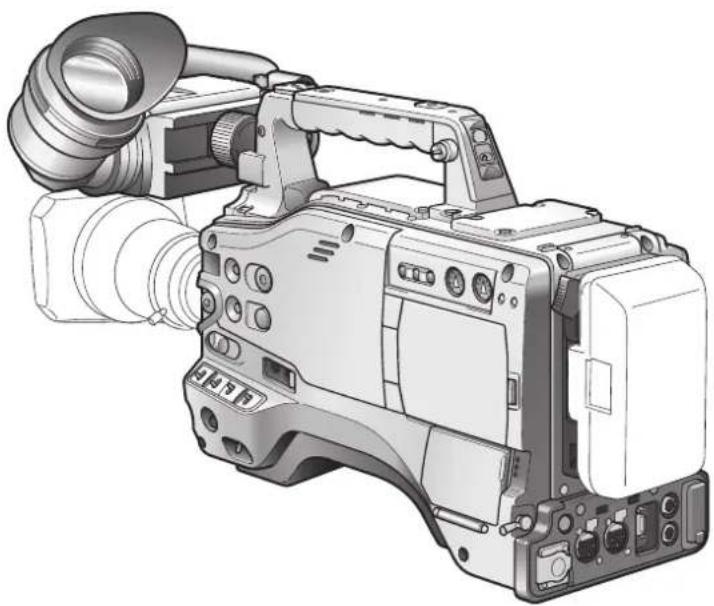
natural_image
Illustration of a video camera with lens and external frame (no text or symbols)FRANÇAIS
Before operating this product, please read the instructions carefully and save this manual for future use.
Read this first!

CAUTION
RISK OF ELECTRIC SHOCK DO NOT OPEN

CAUTION: TO REDUCE THE RISK OF ELECTRIC SHOCK, DO NOT REMOVE COVER (OR BACK). NO USER-SERVICEABLE PARTS INSIDE. REFER SERVICING TO QUALIFIED SERVICE PERSONNEL.

The lightning flash with arrowhead symbol, within an equilateral triangle, is intended to alert the user to the presence of uninsulated "dangerous voltage" within the product's enclosure that may be of sufficient magnitude to constitute a risk of electric shock to persons.

The exclamation point within an equilateral triangle is intended to alert the user to the presence of important operating and maintenance (servicing) instructions in the literature accompanying the appliance.
WARNING:
● TO REDUCE THE RISK OF FIRE OR SHOCK HAZARD, DO NOT EXPOSE THIS EQUIPMENT TO RAIN OR MOISTURE.
● TO REDUCE THE RISK OF FIRE OR SHOCK HAZARD, KEEP THIS EQUIPMENT AWAY FROM ALL LIQUIDS. USE AND STORE ONLY IN LOCATIONS WHICH ARE NOT EXPOSED TO THE RISK OF DRIPPING OR SPLASHING LIQUIDS, AND DO NOT PLACE ANY LIQUID CONTAINERS ON TOP OF THE EQUIPMENT.
CAUTIONS:
TO REDUCE THE RISK OF FIRE OR SHOCK HAZARD AND ANNOYING INTERFERENCE, USE THE RECOMMENDED ACCESSORIES ONLY.
CAUTION:
In order to maintain adequate ventilation, do not install or place this unit in a bookcase, built-in cabinet or any other confined space. To prevent risk of electric shock or fire hazard due to overheating, ensure that curtains and any other materials do not obstruct the ventilation.
FCC Note:
This equipment has been tested and found to comply with the limits for a class A digital device, pursuant to Part 15 of the FCC Rules. These limits are designed to provide reasonable protection against harmful interference when the equipment is operated in a commercial environment. This equipment generates, uses, and can radiate radio frequency energy, and if not installed and used in accordance with the instruction manual, may cause harmful interference to radio communications. Operation of this equipment in a residential area is likely to cause harmful interference in which case the user will be required to correct the interference at his own expense.
Warning:
To assure continued FCC emission limit compliance, the user must use only shielded interface cables when connecting to external units. Also, any unauthorized changes or modifications to this equipment could void the user's authority to operate it.
Caution:
● The interior of this product contains high-voltage components. Do not disassemble the product.
- Do not point the eyepiece directly at the sun.

indicates safety information.
Read this first!
A rechargeable battery that is recyclable powers the product you have purchased.
This product contains a CR Coin Cell Lithium Battery which contains Perchlorate Material — special handling may apply.
See www.dtsc.ca/gov/hazardouswaste.perchlorate.
Attention/Attentie
ENGLISH
- Batteries are used for the main power source and memory back-up in the product. At the end of their useful life, you should not throw them away. Instead, hand them in as small chemical waste.
NETHERLANDS
natural_image
Simple line drawing of a trash bin with an X mark and a circular base (no text or symbols)TO REMOVE BATTERY
Main Power Battery (Ni-Cd / Ni-MH / Li-ion Battery)
- To detach the battery, please proceed in the reverse order of the installation method described in this manual. - If a battery made by any other manufacturer is to be used, check the Operating Instructions accompanying the battery.
Back-up Battery (Lithium Battery)
● For the removal of the battery for disposal at the end of its service life, please consult your dealer.
Precautions for Use
Caution regarding laser beams
The CCD may be damaged if it is subjected to light from a laser beam.
When using the camera-recorder in locations where laser irradiation equipment is used, be careful not to allow the laser beam to shine directly on the lens.
PLEASE NOTE:
- When preparing to record important images, always shoot some advance test footage, to verify that both pictures and sound are being recorded normally.
- Should video or audio recording fail due to a malfunction of this camera-recorder or the P2 cards used, we will not assume liability for such failure.
Disposing and transferring ownership of memory card devices
Formatting or deleting a memory card device in this camera or a PC will only change file management data and leave data on the card intact. It is recommended that the card either be physically destroyed or that commercially sold software be used to completely delete any data on the card. Note that managing card data is the owner's responsibility.
Information on software for this product
- Included with this product is software licensed under the GNU General Public License (GPL) and GNU Lesser General Public License (LGPL), and users are hereby informed that they have the right to obtain, change and redistribute the source codes of this software.
Details on GPL and LGPL can be found on the installation CD provided with the unit. Refer to the folder called "LDOC".
(Details are given in the original (English-language) text.)
To obtain the source codes, go to the following home page:
The manufacturer asks users to refrain from directing inquiries concerning the source codes they have obtained and other details to its representatives.
- Included with this product is software which is licensed under MIT-License.
Details on MIT-License can be found on the installation CD provided with the unit. Refer to the folder called "LDOC".
(Details are given in the original (English-language) text.)
Trademarks
- SD logo is a trademark.
● Multi Media Card (MMC) is a registered trademark of Infineon Technologies AG.
● Apple, Macintosh, Mac OS are registered trademarks or trademarks of Apple, Inc. in the United States and/or other countries.
● Microsoft and Windows are registered trademarks or trademarks of Microsoft Corporation in the United States and/or other countries.
● Other names of companies and products are trademarks or registered trademarks of the respective companies.
Contents
Chapter 1 Introduction
Chapter 2 Parts and their Functions
Chapter 3 Recording and Playback
Chapter 4 Adjustments and Settings for Recording
Precautions for Use ....4
Camera Unit Features ....8
Recording and Playback Features 10
Outline of operations 12
Flow of shooting, playing and saving 12
Saving and editing on external devices 13
System Configuration ....14
Power Supply and Accessory Mounting Section 15
Audio (input) Function Section 16
Audio (output) Function Section 18
Shooting and Recording/Playback Functions Section 19
Menu/Thumbnail Operation Section 24
Time Code Section 25
Warning and Status Display Functions 26
LCD Monitor 26
Viewfinder 27
Setting Date and Time of Internal Clock 28
P2 Cards 30
Inserting P2 Cards 30
Removing P2 Cards ....31
To Prevent Accidental Erasure of P2 Card Content 32
P2 CARD ACCESS LED and status of P2 cards 32
P2 card recording times 32
Handling P2 Card Recording 32
Basic Procedures 34
Shooting 35
Normal Recording 36
Variable Frame Rate (VFR) Recording 37
Native recording 37
Standard recording 38
Using variable frame rates (VFR) 38
Shooting in the 1080i/480i Progressive Mode 39
Special Recording Modes 40
Pre-recording (PRE REC) 40
Interval recording (INTERVAL REC) 40
One-shot recording (ONE-SHOT REC) 41
Loop recording (LOOP REC) 42
Hot Swap Recording 42
Recording Check Function 43
Shot Marker (SHOT MARK) Recording Function 43
Text Memo Recording Function 43
Normal and Variable Speed Playback 44
Video and recording formats 45
Multiple HD/SD formats 45
Selecting recording signals in CAMERA MODE 45
Selecting MCR mode recording and playback signals 46
Selecting video output 46
List of recording, playback and output formats 47
Adjusting the White balance and Black Balance 50
Adjusting the White Balance 50
Adjusting the Black Balance 51
Setting the Electronic Shutter 53
Setting the Shutter Mode and Speed 53
Placing the Camera-recorder in SYNCHRO SCAN Mode 54
Assigning functions to USER buttons 55
Selecting Audio Input Signals and Adjusting Recording Levels 56
Selecting Audio Input Signals 56
Adjusting Recording Levels 56
Selecting Function for the FRONT AUDIO LEVEL Control 57
CH3 and CH4 Recording Levels 57
Setting Time Data 58
Time data overview 58
Chapter 5 Preparation
Chapter 6 Manipulating Clips with Thumbnails
Recording time codes and user bits ....59
Setting user bits 60
Entering the User Bits 60
Setting the Time Code 62
Externally Locking the Time Code 64
Outputting the time code externally 65
GENLOCK and time code input/output connection and setup 66
Counter Setting and Display 66
Viewfinder Screen Status Displays 67
Lamps in the Viewfinder Screen 67
Viewfinder Status Indication Layout 67
Selecting Viewfinder Display Information 67
Screen displays 68
Warnings 71
P2 card playback data indication 71
Errors 72
Camera status display 72
USER buttons assignment information (at mode check) 72
! LED light indication (at mode check) 72
Checking and displaying shooting status 73
Setting the Marker Displays 74
Adjusting and setting the LCD monitor 75
Handling setup data 77
Configuration of setup data files 77
Handling SD memory cards 78
Formatting, Writing and Reading an SD memory card 78
How to Use Scene File Data 79
Saving scene files and other settings on SD memory cards 82
Memory Card Usage 83
Power Supply 84
Mounting the Battery and Setting the Battery Type 84
Use of the external DC power supply 86
Mounting the Viewfinder and Adjusting its Position 88
Mounting the Viewfinder 88
Adjusting Viewfinder Right-Left Position 88
Diopter Adjustments 89
Screen Adjustments 89
Removing the Viewfinder 90
Mounting and Adjusting the Lens 91
Mounting the Lens 91
Adjusting the Lens Flange Back 92
White Shading Compensation 92
Setting Chromatic Aberration Compensation (CAC) 95
Preparing for Audio Input 98
When Using the Front Microphone 98
When Using Audio Devices 99
Attaching Accessories 100
Mounting the Camera on a Tripod 100
Attaching the Shoulder Strap 101
Attaching the Rain Cover 101
Attaching the FRONT AUDIO LEVEL Control Knob 101
Connecting the AJ-RC10G Extension Controller ....102
Thumbnail Operations ....103
Thumbnail Overview 103
Thumbnail Screen 104
Selecting Thumbnails 104
Switching the Thumbnail Display 105
Setting the Thumbnail Display Mode 106
Clip Operations 107
Playing Back Clips 107
Shot Mark 107
Deleting Clips 108
Restoring Clips 108
Chapter 7 Menu Operations
Chapter 8 Connecting to External Devices
Chapter 9 Maintenance and Inspections
Chapter 10 Specifications
Setting of Clip Meta Data ....109
Formatting P2 and SD Memory Cards ....112 Formatting a P2 Card ....12 Formatting SD memory cards ....112
Properties ...... 113 Clip Property ...... 113 P2 Card Status Display ...... 118 SD memory card Status Display ...... 115 Confirmation of Metadata Upload ...... 115
Viewfinder and LCD Menus ....116 Using the menus ....116 Initializing the menu settings ....117
Setup menu structure ....118 Camera (CAM) mode menu ....18 MCR mode menu ....19
Setup menu list ....120 SCENE FILE screen ....120 CAMERA SETUP screen ....121 SW MODE screen ....122 RECORDING SETUP screen ....123 AUDIO SETUP screen ....124 OUTPUT SEL screen ....125 DISPLAY SETUP screen ....125 VF! LED screen ....126 BATTERY SETUP screen ....127 CARD FUNCTION (SD memory card setting) screen ....128 LENS SETUP screen ....128 OTHER FUNCTIONS screen ....129 OPTION MENU screen ....130
Connecting to External Devices Using USB2.0 Port (PC mode) ....13 1 Procedures for establishing a connection with a PC ....13 1
Connecting to External Devices Using the IEEE1394 Connector (PC mode)....132 Procedures for establishing a connection with a PC....132 Procedures for connecting a hard disk....133 Warnings....134
DVCPRO/DV Connection via IEEE1394 Connector ....135 Recording DVCPRO/DV signals input to 1394 connector ....135
Inspections Before Shooting ....137 Preparing for Inspections ....137 Inspecting the Camera Unit ....138 Inspecting the Memory Recording Functions ....138
Maintenance ....141 Cleaning Inside the Viewfinder ....141 Eyepiece Care ....14 Phenomenon Inherent to CCD Cameras ....141 Charging the internal battery ....141
Warning System ....142 Warning Description Tables ....142 Updating Camera Drivers ....144
Dimensions and specifications ....145 Dimensions ....145 Specifications ....146 Connector signal description ....149
Chapter 1 Introduction
The AG-HPX500P/E memory card camera recorder is equipped with a 2/3-inch lens mount system that enables use of high-performance interchangeable lenses, and comes with a 50 Hz/59.94 Hz selector function to permit use of a multitude of HD and SD formats. Also equipped with a variable frame rate feature for cinematic expression and effects. All these features make possible recording of high-quality image content. Four P2 card slots enable extended HD recording and deliver the reliability, speed and IT functionality that only P2 media is capable of revolutionizing the workflow of recording and editing.
Camera Unit Features
■2/3-inch interchangeable lens system
The 2/3-inch bayonet mount for interchangeable lenses provides access to a broad lineup of broadcast and industrial 2/3-inch zoom lenses from a number of manufacturers.
■Progressive 3CCD
The 2/3-inch progressive 3CCD combines a large light-receiving area with high sensitivity. 3CCD pixel-shift technology (1/2 pixel) and advanced digital processing produce a high-resolution CCD. The camera unit provides high resolution and high rate scanning at 1080/60P (or 50P) at all times. This high-resolution native progressive video is used as a source to produce a vertical resolution with a superior HD/SD image quality that an interlace CCD simply cannot match.
■14-bit digital circuit
The high-performance DSP (Digital Signal Processor) in the camera uses 14-bit A/D conversion and 19-bit inner processing to adjust the gamma settings for each of the R, G and B channels of 1080/60P (50P) video, and convert to a variety of HD and SD formats (P/I conversion, line conversion and down conversion). This produces high-quality images in all video formats.
■Multiple HD/SD formats
The camera supports recording in 20 HD and SD image formats making it ready for news gathering, program production, film making and other applications anywhere in the world. 1080i/720P HD recording uses the DVCPRO HD codec for broadcast use while SD recording is performed in DVCPRO50 / DVCPRO/DV multi-codec.
■ Variable frame rate makes speed effects possible (when 720P format is selected)
This camera comes with the variable frame rate feature developed for the VariCam HD Cinema camera. In 720P mode*, the camera enables selection between 11 frame rates between 12P to 60P (50P). This puts features such as undercranking (dropping frames) and overcranking (high frame rate) for quick motion and slow motion cine-like effects at the disposal of the camera crew.
* In 1080 and 480 mode, the camera records at a fixed frame rate of 24P/30P (25P in 1080 and 576 mode, at 50 Hz mode).
■Native mode/Over 60P (50P) mode selectable
- 720PN (native) mode*: Recording is performed at the frame rate set in the camera. Playing back a recording made at a frame rate set in the camera at the normal rate provides speed effects without using a frame rate converter. Native mode also extends the recording time.
●720P over 60P (or 50P) mode: This lets you produce a backup copy by recording the DVCPRO HD stream output from the IEEE1394 connector on a hard disk recorder such as the AJ-HD1400 DVCPRO HD recorder or the FOCUS FS-100 HDD recorder.
* In 720PN (native) mode, the IEEE1394 connector cannot output a DVCPRO HD stream.
■1080/480 24P advance mode
In 59.94Hz mode, recording at 1080/24P or 480/24P allows you to select 24PA (advance) mode. Using 2:3:3:2 pulldown, the 24PA mode performs 60i conversion to enable nonlinear editing* maintaining an image quality that is better than normal 24P (2:3 pulldown). Recording at 30P or 25P (50 Hz mode) applies a 2:2 pulldown.
* For details on compatible systems, visit our website at:
https://eww.pavc.panasonic.co.jp/pro-av/
* 24P, 30P and 60P/60i indicate recording at 23.98P, 29.97P and 59.94P/59.94i, respectively.
■Eight gamma curves, including cine-like gamma
The DSP provides Panasonic's proprietary selectable gamma feature. To expand camera capabilities, the camera offers eight gamma modes including cine-like gamma to give the characteristic warm tone of film recordings and a news gamma curve for newsgathering.
■Slow, synchro and high speed shutter
The shutter speed can be set in a range between 1/12 s to a maximum speed of 1/2000 s. Combined with the variable frame rate functions, this function allows you to create a blurring effect or an undercranking effect. The camera also features a synchro scan function for capturing screen shots from a computer monitor.
■Scene file dial
This dial allows you to instantly retrieve settings that suit shooting conditions. Six preset files are provided, and you can change the file names and their settings as desired. You can also save up to 4 files to an SD memory card and load the files from the card.
■Shooting assist functions
- User buttons: Three user buttons each of which can be assigned a frequently used function for immediate access.
●Focus assist: Displays a frequency distribution graph of the video signal as an aid in focusing.
●Eight files for correcting lens aberration and four files for correcting shading for interchangeable lenses are provided.
● Variable color temperature: Fine adjustment is possible after setting the white balance.
●REC check: Quick check of the last portion recorded results.
●4-position optical ND filter provided.
■Chromatic aberration compensation (CAC)
This function automatically corrects the registration error caused by the slight chromatic aberration that the lens cannot compensate for, in order to minimize color bleeding into surrounding image areas.
■Remote control support
The camera supports the AJ-RC10G (optional accessory) remote control unit. The remote control allows you to adjust camera image and recording controls at a distance while viewing what you are shooting.
Recording and Playback Features
■A variety of interfaces
The AG-HPX500P/E can record 48 kHz/16-bit uncompressed high-quality digital audio in all formats. The 4-channel audio capability makes both microphone and line input possible on up to four channels. HD-SDI output, time code input and output, GEN lock input and USB 2.0 connector are also provided. Also part of standard equipment is an IEEE1394 interface (6-pin) for transfer of all HD/SD signal formats without degradation. This interface allows you to transfer video data for nonlinear editing on a Windows ^ PC or Macintosh ^ with DVCPRO HD compliant software or for backing up on a connected DVCPRO HD digital VTR (AJ-HD1400) or FOCUS FS-100 HDD recorder.
■P2 cards for high capacity, high speed and high reliability
Comprising four SD memory cards, a P2 card is a broadcast industry standard memory card with four times the capacity of a conventional SD memory card in a compact and lightweight (45 g) design. In addition to exceptional resistance to shock, vibration and temperature fluctuations, this semiconductor memory has a reliability that guarantees long-term repeated recording/initialization that a tape or hard disk system with their moving parts could never match. The connectors are professional grade to withstand long-term continual insertion and removal.
AV data is recorded on a P2 card as a single file that is immediately accessible for nonlinear editing or transfer over a network without digitizing. Transfer speeds far surpassing those of hard disks also help to speed up production processes. The P2 card complies with PCMCIA standards and can be directly plugged into the P2 card slot on a notebook PC ^*1 .
The four P2 card slots allow continuous recording on four P2 cards and also offer the following recording capabilities in a memory card camera-recorder.
- Card selection: A card in any slot can be instantly selected (switched to) in standby mode* ^2 . Recorded content can be quickly passed on to editing or transferred to minimize interruptions in recording making it far more efficient than systems where tapes or disks have to be exchanged.
●Hot-swap recording: Cards can be replaced during recording. A full memory card can be replaced while recording is made on another card. Successively swapping cards in this way gives you virtually unlimited recording capacity.
- Loop recording: Setting the camera for consecutive overwriting, you can repeatedly rerecord on the inserted P2 cards, always maintaining a recording of the most recent, specific period of time.
*1 This requires the installation of a P2 card driver (provided with each device). The P2 card driver runs under Windows® Vista, Windows® XP or Windows® 2000.
*2 This assumes that the SLOT SEL function is assigned to a USER button (USER MAIN, USER1 or USER2).
■Immediate startup and reliable data protection
When you press the REC button in standby mode, the camera instantly finds a blank area on the P2 card and begins recording. Unlike a VTR system, there is no need to locate a blank section before recording. It can begin recording immediately even when you are using it to preview video. In normal use, there is no chance of accidentally deleting a recording. Recordings will not be erased unless you intentionally delete a file or initialize the card.
■Other features
●Pre-rec: This function provides a way to capture moments you otherwise would have missed. In the standby mode, the camera will memorize video and audio for up to 3 seconds in HD and 7 seconds in SD. Starting the recording operation will record the preset duration of video and audio already memorized in standby.
●One-shot REC: Convenient for producing animation, this mode records for a set time (from 1 frame to 1 second) each time you press the START button.
- Interval REC: Recording one frame at a time at set intervals (from 2 frames to 10 minutes), this mode is useful for monitoring, supervision and special ultra undercranking effects.
■Clip thumbnail preview
The camera records each cut as a clip (file) and automatically attaches a thumbnail image and file information to it. To preview a clip on the LCD monitor or to check clip data, simply choose the clip you want from the list of thumbnails. These thumbnails and the file data can be viewed on a PC (P2 Viewer *) or processed in a nonlinear editing program.
* "P2 Viewer" is a Windows® PC viewing software that can be downloaded free of charge by P2 card users.
■Shot marker and text memo
If desired, you can add a simple OK/reject shot marker to each clip either during or after recording. When a P2 card is mounted in a PC (P2 Viewer), the PC will display only marked clips.
A text memo function is also provided. Pressing the USER button to which the text memo function has been assigned anywhere in a clip during recording or in preview mode allows you to attach empty post-it like text memos (up to 100) that can later be filled with text on a PC (P2 Viewer).
■SD memory card slot
The camera provides an SD memory card slot for saving and loading scene files and user settings. A metadata upload file (created using P2 Viewer) containing the name of the person who shot the video, the name of the reporter, the shooting location or a text memo and other information can be saved to an SD memory card. This data file can be loaded as clip metadata.
■HD/SD SDI output and downconverter supported
Video line outputs (both BNC) are provided as standard. These outputs can flexibly handle both monitor and line recording. A down-converter is also built-in. Aspect mode can also be selected.
- SDI OUT (HD/SD): The HD-SDI output allows you to make backups on an external VTR (with HD-SDI input) in synch with REC START/STOP button operation. SD-SDI can also down convert and output HD content.
●VIDEO OUT: Outputs down converted SD video (composite video).
■Fine adjustment of sound recording level
The camera features a front-mounted control for fine adjustment of the sound recording level. This control is particularly useful for adjusting the sound level when you have to control both video and audio recording. The control can be disabled.
Outline of operations
This unit is compatible with P2 (Professional Plug-in) cards. Excelling at high transfer speeds, the P2 card enables high vision recording and smooth editing and dubbing.
Flow of shooting, playing and saving
The setting values such as the user file are saved to and read from the SD memory card.

P2 mode shooting and playback (Pages 30 and 34)
P2 card
You can use the following features:
• HD (High Definition) recording
- Multi format recording g
• Variable frame rate s
Slow & quick motion recording g
• Maximum 4 channel uncompressed digital audio recording g
Saving and editing on external devices
Connecting external devices via the USB connector (Page 131)
The data (file) is transferred for nonlinear editing on your computer or other unit.

flowchart
graph TD
    A["Component video cable"] --> B["BNC cable (composite/SDI)"]
    B --> C["Video equipment/Monitor"]
    C --> D["Computer/Memory card recorder"]
    D --> E["External hard disk"]
    E --> F["IEEE1394 (Windows®/Macintosh®)"]
    F --> G["IEEE1394 (SBP-2*)"]
    G --> H["P2 card"]
    H --> I["USB2.0 (Windows®) IEEE1394 (SBP-2*) (Macintosh®)"]
    I --> J["Computer"]
    style A fill:#f9f,stroke:#333
    style D fill:#ccf,stroke:#333
    style E fill:#cfc,stroke:#333
    style F fill:#fcc,stroke:#333
    style G fill:#cff,stroke:#333
    style H fill:#ffc,stroke:#333
    style I fill:#fcf,stroke:#333
*Serial Bus Protocol-2
System Configuration

flowchart
graph TD
    A["AG-HPX500P/E"] --> B["Viewfinder"]
    A --> C["Microphone (Phantom +48 V)"]
    A --> D["Lens (Bayonet type)"]
    A --> E["Rain cover"]
    A --> F["Soft carrying case"]
    A --> G["Hard carrying case"]
    A --> H["Tripod adapter"]
    A --> I["SHAN-TM700"]
    J["Remote control unit"] --> K["AJ-RC10G"]
    K --> L["Remote control cable AJ-C10050G"]
    M["Anton/Bauer Gold Mount type"] --> N["Battery mount"]
    N --> O["(supplied) PROPAC14, TRIMPAC14 HYTRON50/100/140 DIONIC90/160"]
    P["V mount type"] --> Q["Battery plate"]
    Q --> R["ENDURA E-7/7S ENDURA E-10/10S"]
    S["NP-1 type"] --> T["NP-L7 (battery)"]
    U["External power supply"] --> V["SD Memory cards* P2 Cards*"]
    W["LCD monitor"] --> X["BT-LH80W"]
    Y["USB2.0 compatible devices"] --> Z["Ground"]
* For the latest information on P2 cards and SD memory cards not available in the operating Instructions, visit the P2 Support Desk at the following Web sites. https://eww.pavc.panasonic.co.jp/pro-av/
Power Supply and Accessory Mounting Section
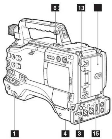

1 POWER switch
Used to turn on/off the power.
2 Battery mount
A battery pack from Anton/Bauer is mounted here.
For details, refer to [Mounting the Battery and Setting the Battery Type] (page 84).
3 DC IN (external power input) socket (XLR, 4P)
This unit is connected to an external AC adapter. For details, refer to [Use of the external DC power supply] (page 86).
4 BREAKER switch
When an excessive amount of current is fed through the video camera recorder, due to any abnormal event, the breaker automatically turns off the power in order to protect the device.
After the interior of the video camera recorder has been checked and/or repaired, this button must be depressed. If there is no unusual reaction, the unit can be powered-up.
5 Light shoe
A video light or similar accessory can be attached here.
6 Shoulder strap fittings
The shoulder strap is attached here.
For details, refer to [Attaching the Shoulder Strap] (page 101).
7 Lens mount (2/3-inch bayonet type)
The lens is attached here.
For details, refer to [Mounting the Lens] (page 91).
8 Lens lever
Tighten this lever to lock the lens to the lens mount.
For details, refer to [Mounting the Lens] (page 91).
9 Lens mount cap
To remove the cap, raise the lens lever.
When the lens is not mounted, replace the cap.
10 Lens cable/microphone cable clamp
This clamp secures the lens and microphone cables.
For details, refer to [Mounting the Lens] (page 91).
11 Tripod mount
When you want to mount the AG-HPX500P/E on a tripod, the optional tripod adapter (SHANTM700) is attached here.
For details, refer to [Mounting the Camera on a Tripod] (page 100).
12 LENS jack (12-pin)
The lens connection cord is connected here.
For a detailed description of your lens, see the relevant manufacturer's instruction manual.
13 Battery release lever
Pull down the release lever to release the battery pack.
14 Viewfinder left-right positioning ring
For details, see [Adjusting Viewfinder Right-Left Position] (page 88).
15 Light control switch
For details, refer to [Power Supply] (page 84).
16 Cable holder
Used to secure the light cable and microphone cable.
Audio (input) Function Section
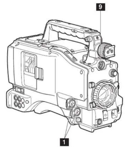

1 MIC IN (microphone input) jacks FRONT1/FRONT2 (XLR, 3-pin)
- Connect microphones (optional accessories) to these jacks. Power for the microphone comes from this jack.
- A phantom-powered microphone may be connected. To use a phantom-powered microphone, set the menu option F.MIC POWER1/F.MIC POWER2 to ON in the
2 AUDIO LEVEL CH1/CH2 (audio channel 1 & 2 recording level adjustment) controls
- With the AUDIO SELECT CH1/CH2 switch positioned to [MAN], these controls can be used to adjust the recording levels for Audio Channels 1/2.
- Note that the controls are designed to be locked. For adjustment, each control must be depressed while turning.
3 AUDIO SELECT CH1/CH2 (audio channel 1 & 2 automatic/manual level adjustment selector) switch
Use this switch to select recording level control mode for Audio Channels 1 and 2.
AUTO: Recording level automatically controlled.
MAN: Recording level manually controlled.
4 AUDIO LEVEL CH3/CH 4 (audio channel 3 & 4 recording level adjustment) controls
Set the menu option AUTO LEVEL CH3/AUTO LEVEL CH4 to OFF in the
5 AUDIO IN (audio input selector) switch
Use this switch to select the signals recorded through Audio Channels 1 - 4.
FRONT: Signal from the microphone connected to the MIC IN jack is recorded.
REAR: Signal from the audio device or microphone connected to the REAR 1/ REAR 2 connector is recorded.
| CH1 Input CH2 Input | ||
| FRONT1 FRONT1 jack FRONT FRONT2 jack | ||
| FRONT2 FRONT2 jack REAR REAR2 ack | ||
| REAR REAR1 jack | — | — |
| CH3 Input CH4 Input | ||
| FRONT FRONT1 jack FRONT FRONT2 jack | ||
| REAR REAR1 jack REAR REAR2 jack | ||
With a front microphone (such as AG-MC200G) connected only to the FRONT2 jack, setting CH1 of the AUDIO IN switch to FRONT2, setting CH2-CH4 to FRONT and setting the MONITOR SELECT CH1/2 / CH3/4 selector switch to CH3/CH4 will result in no sound output to CH3.
6 REAR 1/REAR 2 (audio input channel 1 & 2) connectors (XLR, 3-pin)
Audio devices or a microphone may be connected here.
For details, refer to [When Using Audio Devices] (page 99).
7 LINE/MIC/+48V (line input/mic input/mic input + 48V) selector switch
Used to select the audio signal input from the REAR1/REAR2 connectors.
LINE: Audio signal line-input from the audio device is input.
MIC: Audio signal from a self-powered (active) microphone is input. (The main unit does not supply power to the remote microphone).
+ 48V: Audio signal from a passive microphone is input. (The unit supplies power to the remote microphone).
Power is supplied when R.MIC POWER in the
8 FRONT AUDIO LEVEL (audio recording level adjustment) control
- This control adjusts the recording level of Audio Channels 1 and 2.
- Level adjustment is possible when the AUDIO SELECT switch is set to MAN.
- Use the menu options FRONT VR CH1 and FRONT VR CH2 in the
9 Viewfinder connector
For details, refer to [Mounting the Viewfinder] (page 88).
Audio (output) Function Section
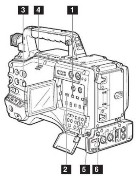

natural_image
Technical line drawing of a handheld electronic device with ports and buttons (no text or symbols)1 MONITOR SELECT (audio channel) CH1/2 / CH3/4 selector switch
Use this switch to select the audio channel whose signals are output to the speakers, earphones or AUDIO OUT connector.
CH1/2: Signals on Audio Channels 1 and 2 are output.
CH3/4: Signals on Audio Channels 3 and 4 are output.
The channel indications on the display window and on the audio level meter in the viewfinder are synchronised with this selector switch.
2 MONITOR SELECT (audio selection) CH1/3 / ST / CH2/4 selector switch
In combination with the MONITOR SELECT CH1/2 / CH3/4 switch, select the audio signal output to the speakers and earphones, and from the AUDIO OUT connector.
| MONITOR SELECT (Left) | MONITOR SELECT (Right) | ||
| CH1/2 CH3/4 | |||
| MONITOR SELECT | CH1/3 Audio | Channel 1 Audio Channel 3 | |
| ST | Stereo signals fromAudio Channels 1 and 2 | Stereo signals fromAudio Channels 3 and 4 | |
| CH2/4 Audio | Channel 2 Audio Channel 4 | ||
3 MONITOR/ALARM (volume) control
Used to control the volume of sound output from the monitor speakers and earphones.
It also adjusts the alarm sound volume.
4 Speakers
The speakers output EE sound during recording, and reproduced sound during playback. The speakers emit an alarm sound when the warning lamp blinks and/or the indicator activates. EE sound and playback sound are not output during alarm sound output.
When the PHONES jack is connected with earphones, sound from the speaker is automatically muted.
5 PHONES (earphones) jack (mini jack)
This connector is designed for audio monitoring (stereo) earphones. When earphones are connected, sound from the speakers is automatically muted.
6 DC OUT (DC power supply) output socket
This output socket is designed for 12-VDC. It provides a maximum current of 1.5 A.
7 AUDIO OUT connector
- This connector outputs audio signals recorded on Channels 1/2 or 3/4.
- Output signals are selected with the MONITOR SELECT CH1/2 / CH3/4 selector switch.
Shooting and Recording/Playback Functions Section

Shooting and Recording (camera unit)
1 ND FILTER (filter switching) control
This control adjusts the amount of light entering the CCD. Use this control in strong outdoor lighting.
| Control position | Setting | Description |
| 1 OFF | Do not use the ND filter. | |
| 2 1/4 | Reduces the amount of light entering the CCD to 1/4. | |
| 3 1/16 | Reduces the amount of light entering the CCD to 1/16. | |
| 4 1/64 | Reduces the amount of light entering the CCD to 1/64. | |
2 USER MAIN, USER 1 and USER 2 buttons
These buttons can be assigned user-selected functions, using a menu option. Each button, when pressed, performs the assigned function. For more information, see [Assigning Functions to USER Buttons] (page 55).
3 SHUTTER switch
Used to enable or disable the electronic shutter.
OFF: Electronic shutter disabled.
ON: Electronic shutter enabled.
SEL: Used to change the speed of the electronic shutter.
This dial switch returns to its original position. Each turn of the switch alters the shutter speed. For more information, see [Setting the Electronic Shutter] (page 53).
4 AUTO W/B (white/black) BAL switch
| AWB | Automatically adjusts the white balance. Set the WHITE BAL switch on the side to [A] or [B] and use this switch to adjust the white balance, which takes a few seconds. The adjusted value is stored in memory. When the WHITE BAL switch is set to PRST and the color temperature is indicated with the AUTO W/B BAL switch set to AWB, setting the switch to AWB again makes it possible to change the preset color temperature. |
| ABB Back | balance is automatically adjusted. |
For details, refer to [Adjusting the White Balance and Black Balance] (page 50).
5 GAIN selector switch
- This switch adjusts video amplifier gain to suit ambient lighting conditions at the time of the shooting.
- Use the menu options MID GAIN and HIGH GAIN in the
screen to set the M/H position gain values. - The factory settings for L, M and H are 0 dB, 6 dB, and 12 dB, respectively.
The camera is locked to 0 dB gain regardless of GAIN switch position and setting when the FRAME RATE is 22 fps (59.94 Hz) or less than 23 fps (50 Hz).
6 OUTPUT/AUTO KNEE selector switch
This switch selects the video signals sent from the camera unit to the memory card recorder unit, viewfinder and video monitor.
| CAM. AUTO KNEE ON | Video being recorded through the camera is output with the AUTO KNEE circuit activated. The compression level (KNEE point) of the video signal is automatically changed according to the received signal. |
| CAM. AUTO KNEE OFF | Video being recorded through the camera is output with the AUTO KNEE circuit turned off. The KNEE point is locked to the level set in the menu. |
| BARS | Color bar signals are output with the AUTO KNEE circuit turned off. |
■AUTO KNEE function
Usually, when you adjust levels to shoot people or scenery against a strongly lit background, the background will be totally whited-out, with buildings and other objects blurred.
In this case, the AUTO KNEE function reproduces the background clearly.
This function is effective when:
- The subject is a person positioned in the shade under a clear sky.
- The subject is a person inside a car or building, and you also want to capture the background visible through a window.
• The subject is a high-contrast scene.
7 WHITE BAL (white balance memory selector) switch
Used to select the white balance adjustment method.
PRST: Use this when you have no time to adjust the white balance.
- The value for the white balance is factory-set to 3200 K.
- While the setting menu or the color temperature is displayed, turn the AUTO W/B BAL switch to AWB to set the color temperature to 3200K or 5600K.
A • B: Pressing the AUTO W/B BAL Switch toward [AWB] automatically adjusts the white balance, saving the adjusted value in Memory A or B. For more information, see [Adjusting the White Balance] (page 50).
8 DISP/MODE CHK button
- Press this button to turn off the LCD monitor and viewfinder display. (The time code indication stays on.)
- A second press of the button turns the display back on and holding it down displays shooting conditions and functions assigned to USER switches.
- It also serves to turn off the alarm sound.
9 MODE button
- This button toggles between the CAMERA mode and MCR mode at each press.
- Holding down this button for 2 seconds or longer in the MCR mode will engage the PC mode. Since this button does not work in the PC mode, power off the camera to exit the PC mode and switch to another mode. The camera will start up in the CAMERA mode when powered up next time.
- Use the mode LED to check current mode.

Chapter 2 Parts and their Functions

Shooting and Recording/Playback Function Section (recording)
10 REC START/STOP button
Pressing this button starts recording, pressing again stops recording. This button has the same function as the VTR button at the lens.
When pressed in the MCR mode, the camera automatically switches to the CAMERA mode and starts recording.
11 SAVE switch
This switch selects the power saving mode.
ON: Forcibly turns off the LCD.
OFF: LCD is on.
The operating status display in the viewfinder goes off when the SAVE switch is set to ON. But it remains on during special recording.
12 OUTPUT CHARACTER switch
This switch controls the superimposition of characters onto the video output (VIDEO OUT, COMPONENT OUT and SDI OUT) to indicate status or menus.
ON: Superimposes characters.
OFF: Does not superimpose characters.
13 REW (fast-reverse) button
During pause, this button performs fast-reverse playback.
During playback, it fast-reverses playback at about 4x normal speed.
If this button is pressed when playback is paused, the beginning of the clip being played is located in pause mode (cue-up mode).
14 F (fast forward) button
During pause, this button performs fast playback. During playback, it performs fast playback at about 4× normal speed.
If this button is pressed when playback is paused, the beginning of the next clip is located in pause mode (cue-up mode).
15 ■ STOP button
This button stops playback.
The menu cursor moves in the thumbnail display.
16 PLAY button
This button is used to view playback using the viewfinder screen or a color video monitor.
17 STILL (pause) button
Press to pause playback.
18 REC buttons (red and white)
Press the red and white buttons simultaneously to start recording the 1394 input signal and press the STOP button to stop recording.
To record 1394 input signals, be sure to set the MCR format to the input signal format before starting recording. Do not change the format or terminate signal input during recording.
19 P2 CARD ACCESS LED
This LED indicates the recording and playback status of each card.
For details, refer to [P2 CARD ACCESS LED and status of P2 cards] (page 32).
20 Slide lock button
Used to open the slide-out door for inserting P2 cards. While depressing this button, slide the door to the left.
21 USB 2.0 connector
Connect a USB 2.0 cable to this connector.
Select USB DEVICE under the menu option PC MODE in the
22 GENLOCK IN connector
This connector inputs a reference signal when the camera unit is gen-locked, or when the time code is externally locked.
- The reference signal must be a Y signal (1080/60i, 720/60P, 1080/50i or 720/50P) (HD) or a composite signal (480/60i or 576/50i).
• GENLOCK cannot be engaged during playback.
23 REMOTE (remote control) connector
By connecting the extension control unit AJ-RC10G (optional accessory), some functions of the camera can be remote-controlled.
For details, refer to [Connecting the AJ-RC10G Extension Controller] (page 102).
24 VIDEO OUT (video signal output) connector
This connector outputs video signals.
- In HD mode, down-converted composite video signals are output.
- Use the DOWNCON MODE in the setup menu DISPLAY SETUP screen to change output. (The factory setting is LETTER BOX.)
13 to 18 work only in MCR mode.
25 SD memory card insertion slot
Insert an SD memory card (optional accessory) in this slot. It is used for uploading meta data as well as for reading and writing USER files and SCENE files.
■SD memory card precautions
- Use only cards that conform to the SD card standard or the SDHC standard in this camera.
- Multimedia cards (MMC) cannot be used. (Use of such cards may prevent recording.)
- Be sure to use mini SD card adapter only when using mini SD cards. (Note that this camera will not operate normally when a mini SD adapter is installed without also inserting a card. Be sure to insert a card when an adapter is installed.)
- Use of Panasonic SD/SDHC memory cards and mini SD cards is recommended. Be sure to format such cards in this camera.
- To format a memory card on a PC, use the dedicated software that can be downloaded from the support site listed below.
- This camera supports 8 MB, 16 MB, 32 MB, 64 MB, 128 MB, 256 MB, 512 MB, 1 GB and 2 GB SD memory cards and 4 GB SDHC memory cards.
- For the latest information not available in the Operating Instructions, visit the P2 Support site at the above Web site.
■About SD and SDHC memory cards
• SD logo is a trademark.
- The SDHC (SD High Capacity) card is a new standard, established by the SD Card Association in 2006, for large-scale memory cards with capacities above 2 GB.
- Multi Media Card (MMC) is a registered trademark of Infineon Technologies AG.
26 BUSY (operation mode display) lamp
This lamp indicates the active status of the SD memory card.
It stays illuminated when the card is active.
While the lamp is on, do not insert or remove the card.
27 R-SIDE P2 card access LED
This LED indicates access status for all four P2 card slots. It blinks when any of the inserted P2 cards is accessed and lights when a card is inserted.
For details, refer to [P2 CARD ACCESS LED and status of P2 cards] (page 32).
28 COMPONENT OUT connector (D4 connector)
- This connector outputs component video signals.
- Use the menu option CMPNT/SDI SEL in the setting menu
29 1394 connector
- Connect an IEEE1394 cable to this connector.
- Select 1394 DEVICE or 1394 HOST under the menu option PC MODE in the
screen to send data via the 1394 connector.
For details, refer to [Connecting to External Devices Using the IEEE1394 Connector (PC mode)] (page 132).
30 SDI OUT connector
• This connector outputs SDI signals.
- Use the menu option CMPNT/SDI SEL in the setting menu
31 SCENE FILE dial
This dial allows you to load and set the shooting conditions for a scene file already recorded with the conditions corresponding to the dial position.
During recording, selecting a position with a different frame rate will not change the frame rate until the camera is set to recording standby mode.
For details, refer to [How to Use Scene File Data] (page 79).
32 PAGE/VAR button
- In the thumbnail display, press this button to turn pages.
- During variable speed playback press this button to change playback speed and in still mode, press to start frame-by-frame playback.
33 FOCUS ASSIST button
This button turns focus assist on and off. Turning on the focus assist function displays a frequency distribution graph in the top right corner of the viewfinder and LCD display. Turn the focus ring on the lens to place the graph further to the right.

natural_image
Abstract wavy line pattern on a gray background (no text or symbols)When the image is out of focus

natural_image
Abstract wavy line pattern on a gray background (no text or symbols)The white area moves to the right as the image comes into focus.
34 Recording enable/disable switch
This switch enables/disables the REC START/STOP button on the handle.
ON: Enables the REC START/STOP button.
OFF: Disables the REC START/STOP button.
Menu/Thumbnail Operation Section

1 MENU button
- Press and hold this button to display the setting menu and press it again to return to the previous image.
- This button is not available in the thumbnail display.
Use the SET button or the JOG dial button to go between menus and select items. For details, see section [Viewfinder and LCD menus] (page 116).
2 Thumbnail button
In MCR mode, press this button to switch between the thumbnail screen and 1394 input mode. Note that this switchover is not performed during recording or playback.
3 Thumbnail menu button
In thumbnail display mode, use this button to access thumbnail menu functions to delete clips, for example.
Use the CURSOR and SET buttons to select thumbnails and access menu functions. For details, see [Manipulating Clips with Thumbnails] (page 103).
4 MODE button
This button toggles between the CAMERA mode and MCR mode. For details, see [Shooting and Recording/Playback Function Section] (page 19).
5 CURSOR and SET buttons
Use these buttons to manipulate menus, the menu bar and thumbnails.
The four triangular buttons are CURSOR buttons and the square center button is the SET button.
6 PAGE/VAR button
Pressing this button during thumbnail display scrolls thumbnail pages forwards and backwards in page units.
7 JOG dial button
- Use this button to go between menu pages and to select and set items in open setting menus (camera menu or MCR menu).
- In a setting menu, turning the JOG dial downwards moves the menu cursor downwards and turning it upwards moves the menu cursor upwards.
Press the JOG dial button to confirm made settings.
Time Code Section

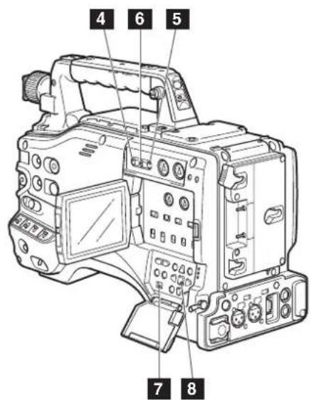
1 GENLOCK IN connector (BNC)
This connector is used to input a reference signal before the camera unit is gen-locked, or before the time code is externally locked. For details, refer to [Externally Locking the Time Code] (page 64).
2 TC IN connector (BNC)
This connector is used to input a reference time code when you externally lock the time code. For details, refer to [Externally Locking the Time Code] (page 64).
3 TC OUT connector (BNC)
When you inter-lock the time code of the AG-HPX500P/E with that of an external device this must be connected with the time code input (TC IN) connector of the external device. For details, refer to [Outputting the time code externally] (page 65).
4 HOLD button
Pressing this button freezes the time data indication on the counter. Note that time code generation continues. Pressing the button again reactivates the counter. This function is used to ascertain the time code or CTL count of a particular recorded scene.
5 RESET button
Use this button to reset the counter value on the time code display to 0:00:00. When the TCG switch is positioned at [SET] and the setting menus TC PRESET screen and UB PRESET screen are open, press this button to reset all set values to 0 and press the SET button to preset.
6 COUNTER (counter display selector) button
The LCD monitor and the viewfinder show the counter value, time code, user bit and frame rate data.
7 TCG (time code selector) switch
This switch is used to specify the stepping mode for the built-in time code generator.
| F-RUN | Select this position to continuously advance the time code independently of the P2 card recording status. Use this mode to synchronise the time code with the time of day, or to externally lock the time code. |
| SET | Select this position to set the time code and/or user bits. |
| R-RUN | Select this position to advance the time code only during recording. The time code is continuously recorded during normal recording. But deleting clips and continuing recording of clips at a frame rate of 24P or 24PA that have been recorded at any other frame rate may break the sequence of time code recording. |
Always use the CURSOR and SET buttons to set the time code and user bits. The JOG dial button cannot be used for this purpose.
8 CURSOR and SET buttons
Use these buttons to set the time code and user bits.
The four triangular buttons are the CURSOR buttons, and the center rectangular one is the SET button.
For guidance in setting the time code and user bits, see [Setting Time Data] (page 58).
Warning and Status Display Functions

1 Back tally lamp
When the BACK TALLY switch is set to [ON], the lamp behaves in the same way as the front tally lamp at the viewfinder.
2 BACK TALLY switch
This switch controls the action of the back and rear tally lamps.
ON: Back and rear tally lamps enabled.
OFF: Back and rear tally lamps disabled.
3 WARNING lamp
This lamp starts blinking or lights up if something unusual occurs in the memory.
4 Rear tally lamp
When the BACK TALLY switch is set on [ON], the rear tally lamp behaves in the same way as the back tally lamp.
5 Mode LED
Shows the camera unit mode.
CAM: Lights red in CAMERA mode.
MCR: Lights green in MCR mode.
PC: Lights orange in PC mode.
LCD Monitor

1 LCD monitor
The LCD monitor displays the video in the viewfinder.
Alternatively, it can show clips on the P2 card in a thumbnail format.
In thumbnail display mode, you can use the
thumbnail menu buttons, CURSOR and SET
buttons to manipulate or delete clips, or format P2 cards.
For details, refer to [Adjusting and setting the LCD monitor] (page 75).
2 OPEN button
Used to open the LCD monitor.
Viewfinder

1 Viewfinder (supplied accessory)
During recording or playback, the viewfinder displays the video image in monochrome. It also displays warnings, messages, zebra patterns, markers (safety zone and center markers), etc.
2 ZEBRA (zebra pattern) switch
This switch is used to display the zebra pattern in the viewfinder.
ON: Zebra pattern displayed.
OFF: No zebra pattern displayed.
3 TALLY switch
Used to control the front tally lamp.
ON: Tally lamp goes on.
OFF: Tally lamp goes out.
4 PEAKING control
Used to adjust the outlines of the video image in the viewfinder for easier focusing. Recorded video and output camera signals are not affected.
5 CONTRAST control
Used to adjust the contrast of the video image in the viewfinder. Recorded video and output camera signals are not affected.
6 BRIGHT control
Used to adjust the brightness of the video image in the viewfinder. Recorded video and output camera signals are not affected.
7 Front tally lamp
This lamp goes on during recording when the TALLY switch is set to [ON]. It also blinks in synchronisation with the REC lamp in the viewfinder, and provides alerts.
8 Viewfinder securing screw
Used to attach or remove the viewfinder.
9 Eyepiece
10 Diopter adjustment ring
Use this to make adjustments in line with your diopter, in order to obtain optimum clarity in the viewfinder image.
11 Connecting plug
12 Locking button
13 Microphone holder
Chapter3
Recording and Playback
Setting Date and Time of Internal Clock
The CLOCK SET value is recorded in the contents (clip), and affects the sequence of playback of the thumbnails. Before carrying out recording, be sure to check and set CLOCK SET and TIME ZONE.
- This shows you how to adjust the calendar to 5:20 PM on December 25, 2007.
1 Set the POWER switch to ON.
2 Press the MENU button.
3 Use the JOG dial button to select setting menu OTHER FUNCTIONS, then press the JOG dial button to open the OTHER FUNCTIONS screen.
For details on menu operation, refer to [Using the menus] (page 116).
4 Use the JOG dial button to select TIME ZONE, then press the JOG dial button.
5 Turn the JOG dial button to set the time difference from Greenwich Mean Time.
- Check what time zone you are in and set accordingly.
OTHER FUNCTIONS
TIME ZONE
LANGUAGE
GL SELECT
GL PHASE
H PHASE
SYSEM FREQ
+ 9:00
ENGLISH
SDI
OFF
59.94Hz
PUSH MENU TO RETURN
■Time zone
| Time difference | Area | Time difference | Area |
| 00:00 Greenwich -00:30 | |||
| -01:00 Azores Islands -01:30 | |||
| -02:00 Mid-Atlantic -02:30 | |||
| -03:00 Buenos Aires -03:30 | Newfoundland Island | ||
| -04:00 Halifax -04:30 | |||
| -05:00 New York -05:30 | |||
| -06:00 Chicago -06:30 | |||
| -07:00 Denver -07:30 | |||
| -08:00 Los Angeles | -08:30 | ||
| -09:00 Alaska | -09:30 | Marquesas Islands | |
| -10:00 Hawaii | -10:30 | ||
| -11:00 Midway Island | -11:30 | ||
| -12:00 Kwajalein | +11:30 | Norfolk Island | |
| +13:00 | +10:30 | Lord Howe Island | |
| +12:00 New Zealand +09:30 | Darwin | ||
| +11:00 Solomon Islands | +08:30 | ||
| +10:00 Guam | +07:30 | ||
| +09:00 Tokyo | +06:30 | Rangoon | |
| +08:00 Beijing | +05:30 | Bombay | |
| +07:00 Bangkok | +04:30 | Kabul | |
| +06:00 Dacca | +03:30 | Tehran | |
| +05:00 Islamabad +02:30 | |||
| +04:00 Abu Dhabi | +01:30 | ||
| +03:00 Moscow | +00:30 | ||
| +02:00 Eastern Europe | +12:45 | Chatham Islands | |
| +01:00 Central Europe | |||
- The clock is accurate to within about ± 30 seconds a month with the power turned off.
- Check and set the time when accurate time is required. After setting the time, change the setting menu TIME ZONE item and the display and the recorded local time will be reset accordingly.
6 Select YES at the CLOCK SET item in OTHER FUNCTIONS, then press the JOG dial button.
- The CLOCK SET screen appears.

7 Turn the JOG dial button to select YEAR, then press the JOG dial button.
CLOCK SET
YEAR 2007 MONTH MAY DAY 1 HOUR 13 MIN 7
PUSH MENU TO RETURN
8 Turn the JOG dial button to set YEAR to 2007, then press the JOG dial button.
• A year between 2000 to 2030 can be set.
9 Turn the JOG dial button to select MONTH, then press the JOG dial button.
10 Turn the JOG dial button to set MONTH to DEC, then press the JOG dial button.
11 Set DAY, HOUR and MIN in the same way as setting YEAR and MONTH.
• This is a 24-hour clock.
CLOCK SET
YEAR 2007
MONTH DEC
DAY 25
HOUR 17
MIN 20
PUSH MENU TO RETURN
P2 Cards
Inserting P2 Cards
When using the camera recorder for the first time, be sure to set the time data beforehand. On how the time data is set, see [Setting Date and Time of Internal Clock] (page 28).
1 Turn on the POWER switch.
2 While pressing the slide lock button, move the slide-out door to the left.
- The door opens.
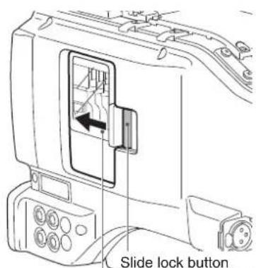
Slide-out door
3 Insert a P2 card in a P2 card slot.
- Press in the card until the eject button pops up.
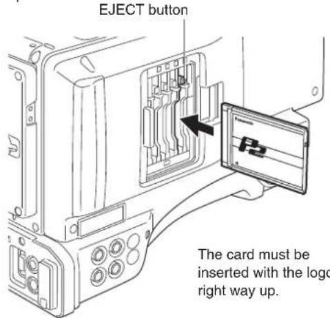
4 Tilt up the popped-up EJECT button.
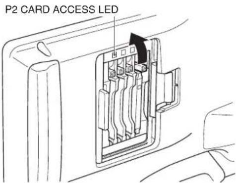
- Insert a P2 card into the AG-HPX500P/E. The P2 CARD ACCESS LED for the appropriate slot indicates the status of the P2 card. For how the P2 card status is indicated, see [P2 CARD ACCESS LED and status of P2 cards] (page 32).
5 Close the slide-out door.
- To prevent cards from falling out, dust from entering and reduce the risk of exposure to static electricity, do not move the AG-HPX500P/E with the slide-out door open.
- Format P2 cards on a P2 device or on a PC using P2 Viewer software.
Removing P2 Cards
1 While pressing the slide lock button, move the slide-out door to the left.
2 Tilt down the EJECT button.
3 Then depress the eject button to release the P2 card.

natural_image
Diagram showing two views of a device with internal components and directional arrows indicating movement (no text or symbols)Tilt down the EJECT button.
Depress the tilted-down EJECT button to release the P2 card.
- When a P2 card is being accessed or it is being recognised after insertion (P2 CARD ACCESS LED blinks in orange), do not remove the P2 card. Removing a P2 card during access could damage it.
- If a P2 card being accessed is removed, the viewfinder displays "TURN POWER OFF" and the AG-HPX500P/E gives a warning using an alarm and the WARNING LED. In addition, all P2 CARD ACCESS LEDs blink rapidly in orange. If this is the case, turn the power off. For more information on warning indications, see [Warning System] (page 142).
- Removing a P2 card during access may corrupt clip data. Check the clips and restore them if required. For more information about how to restore clips, see [Restoring Clips] (page 108).
- If a P2 card being formatted is removed, it may be not be formatted properly. In this case, the viewfinder displays "TURN POWER OFF". If this message appears, turn off the power, then restart the AG-HPX500P/E to reformat the card.
- If a P2 card is inserted while another P2 card is being played back, the inserted P2 card is not recognised and the P2 CARD ACCESS LED for that card does not come on. Card recognition starts when the playback ends.
- A P2 card inserted in an empty slot during recording may not be immediately recognized during the following events.
- Immediately following PRE REC operation
- Immediately before or after a recording that bridges P2 cards in two slots (hot swap recording, etc.)
- The P2 CARD ACCESS LED can be set to stay off in the setup menus, OTHER FUNCTIONS screen, ACCESS LED. When the camera is used in this way, remove cards when the camera has been powered down or a sufficiently long time after terminating recording, playback and other operating modes.
- Removing a P2 card during thumbnail display terminates the thumbnail display.
- A P2 card inserted in an empty slot during interval recording or one-shot recording is not recognized and cannot be used in the recording. The card will be recognized when the recording is completed.
To Prevent Accidental Erasure of P2 Card Content
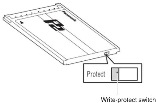
To prevent the content of a P2 card being accidentally erased, position the write-protect switch on the P2 card at [Protect].
Write-protect switchover can be performed while the card is being accessed (during recording or playback), but does not take effect until access to the card ceases.
P2 CARD ACCESS LED and status of P2 cards
| P2 CARD ACCESS LED | Status of P2 Card | |
| Stays on in green | Recording enabled | Writing and reading enabled. |
| Stays on in orange | Selected for recording | Writing and reading enabled for current recording mode (loop, interval or one-shot recording). |
| Blinks in orange | Being accessed | Writing or reading being performed. |
| Quickly blinks in orange | Being recognized | The P2 card is being recognised. |
| Blinks in green | Card full | The P2 card has no free space. Only reading is enabled. |
| Write-protected | The write-protect switch on the P2 card is positioned at [PROTECT]. Only reading is enabled. | |
| Stays off | Card not supported | The card is not supported by your AG-HPX500P/E. Replace the card. |
| Incorrect format | The P2 card is not properly formatted. Reformat the card. | |
| Card not inserted | No P2 card is inserted. Card recognition standby. | |
The ACCESS LED in the LCD monitor blinks when any of the cards in slots 1 to 4 is being recorded or read, and lights to indicate that the camera is ready to record. The ACCESS LED is off when none of the inserted P2 cards is available for recording.
P2 card recording times
| Model number | AJ-P2 C004HG | AJ-P2 C008HG | AJ-P2 C016RG |
| Capacity 4GB | 8GB 16GB | ||
| DVCPRO HD* | Approx. 4 min. | Approx. 8 min. | Approx. 16 min |
| DVCPRO HD 720P/24PN | Approx. 10 min. | Approx. 20 min. | Approx. 40 min. |
| DVCPRO HD 720P/30PN 720P/25PN | Approx. 8 min. | Approx. 16 min | Approx. 32 min. |
| DVCPRO50 Audio 4CH | Approx. 8 min. | Approx. 16 min | Approx. 32 min. |
| DVCPRO/DV Audio 2CH | Approx. 16 min | Approx. 32 min. | Approx. 64 min. |
* DVCPRO HD excludes 720P/30PN, 720P/24PN and 720P/25PN.
- This camera cannot use AJ-P2C002SG (2 GB) cards.
- The indicated capacities include a management area so the total area available for recording is somewhat smaller.
Splitting clips recorded on P2 cards
This camera will automatically generate additional clips for a continuous recording on an 8 GB or higher capacity P2 card when the recording exceeds the durations given below. Even so, a P2 device will handle such clips as a single clip in thumbnail operations (display, delete, recover, copy, etc.). Such recordings may be handled as separate clips by nonlinear editing software or a PC.
| Recording format Recording time |
| DVCPRO HD* Approx. 5 min. |
| DVCPRO50 Approx. 10 min. |
| DVCPRO/DV Approx. 20 min. |
* DVCPRO HD excludes 720P/30PN, 720P/24PN and 720P/25PN.
- Use of cards other than the above may require updating the camera driver. For details, see [Updating Camera Drivers] (page 144).
- For the latest information not available in the Operating Instructions, visit the P2 Support Desk at the following Web site.
https://eww.pavc.panasonic.co.jp/pro-av/
Handling P2 Card Recording
The P2 card is a semiconductor memory card designed for the DVCPRO P2 series, Panasonic's line of professional video and broadcast equipment.
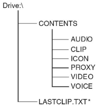
- The DVCPRO P2 format records data as files, making it ideal for computer processing and compatibility. A proprietary format is used for the structure of these files, where in addition to video and audio data recorded in MXF format, various relevant metadata is recorded in the folder structure shown below.
flowchart
graph TD
    A["Drive:\"] --> B["CONTENTS"]
    B --> C["AUDIO"]
    B --> D["CLIP"]
    B --> E["ICON"]
    B --> F["PROXY"]
    B --> G["VIDEO"]
    B --> H["VOICE"]
    A --> I["LASTCLIP.TXT*"]
All these folders are required.
* This file contains the last clip data recorded on a P2 device.
If any of this data is changed or lost, it will not be recognized as P2 data or the P2 card may no longer be possible to use in a P2 device.
- To prevent data loss in transferring P2 card data to a PC or write back PC data on a P2 card, use P2 Viewer, which can be downloaded from the Web site listed below. (Supported operating systems: Windows 2000, Windows XP, Windows Vista) https://eww.pavc.panasonic.co.jp/pro-av/
-
Follow the steps below to use general software such as Microsoft Windows Explorer or Apple Finder to transfer the data to a PC. Be sure to use P2 Viewer to write data back to a P2 card.
-
Treat the CONTENTS folder and the LASTCLIP. TXT file as a unit.
- Do not modify the data below the CONTENTS folder.
- In copying, be sure to copy both the CONTENTS folder and the LASTCLIP.TXT file together.
- When transferring data from multiple P2 cards, create separate folders for each P2 card to prevent overwriting clips with identical names.
- Do not delete data on a P2 card.
- Format P2 cards only on a P2 card device.
Basic Procedures
This section describes the basic procedure for shooting and recording. Before you embark on a shoot, pre-inspect your system to ensure that it works properly. For directions on inspecting your memory card camera-recorder, see [Inspections Before Shooting] (page 137).
Battery Set-up to P2 card Insertion
1 Insert a charged battery pack.
2 Turn the POWER switch to ON to check the battery remaining level in the viewfinder.
- When battery capacity is low, replace it with a fully charged battery. (Note) When low battery capacity is indicated after replacing a battery with a fully charged battery, check battery installation.
3 Insert a P2 card and ensure that the P2 CARD ACCESS LED stays on in orange or green. Then, close the slide-out door.
- When more than one P2 card slot contains a P2 card, the card in the slot with the lowest number is used first. However, regardless of slot number, a P2 card inserted later will not be accessed until the other cards have been used.
Example: If all four slots contain P2 cards, the cards are used in order of slot numbers 1→2→3→4. However, if the P2 card in Slot 1 is removed and then re-inserted, the cards will be used in the following order: 2→3→4→1.

Note that the recording order is retained even if the power is turned off. When the power is next turned on, the last card written before powering-down will be the target card.
Setting the switches before shooting and recording
When a battery and P2 cards are installed, set the switches as detailed below, before starting to use your AG-HPX500P/E.
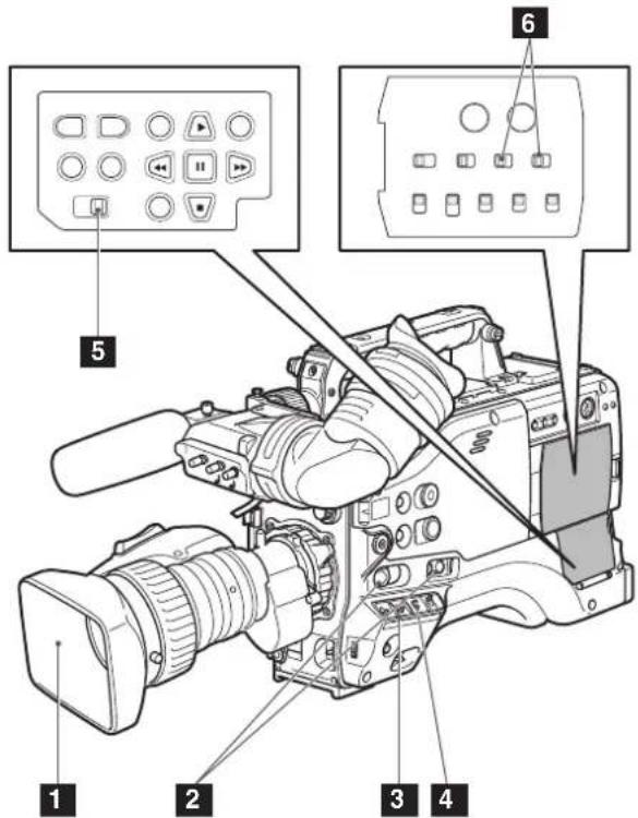
1 Iris
The iris is automatically adjusted when the lens is set to the auto iris mode.
2 USER MAIN/USER1/USER2
Assigning the SLOT SEL function to a USER button allows you to select a P2 card among multiple P2 cards for recording.
The P2 card selected for recording switches with each press of the USER button, and the P2 CARD ACCESS LED of the selected P2 card lights orange. The slot number of the card to be recorded appears in green in the LCD monitor and the viewfinder.
For more information on viewfinder displays, see [Viewfinder Status Indication Layout] (page 67).
3 GAIN switch
Normally, this should be set to L (0 dB). If conditions are too dark, an appropriate gain level should be set.
4 AUTO KNEE selector switch
Set to ON or OFF. Turning OFF the AUTO KNEE selector switch allows you to select one of three settings in the setting menu SCENE FILE.
5 TCG
Set to F-RUN or R-RUN.
6 AUDIO SELECT CH 1/CH 2
Set to AUTO.
- The slot selected for recording cannot be changed when recording has started.
- Use the USER MAIN/USER1/USER2 item in setting menu SW MODE screen to assign functions to the USER MAIN/USER1/USER2 button.
Shooting
White/Black Balance Adjustment to Recording Completion
For shooting, follow the steps below.

1 Use the ND FILTER control to select a filter according to light conditions.
2 ■ When the white balance is saved:
- Position the WHITE BAL switch to [A] or [B].
■ When the white or black balance is not saved and you have no time to adjust the white balance:
- Position the WHITE BAL switch to [PRST].
- The color temperature can be set to 3200K or 5600K.
■ If the white balance is adjusted on the spot:
- Select a filter according to light conditions. Then, position the WHITE BAL switch to [A] or [B] and shoot a white test subject so that it appears at the center of the screen. Then, follow the steps below to adjust the white balance.
-
Turn the AUTO W/B BAL switch toward [AWB] to adjust the white balance.
-
Turn the AUTO W/B BAL switch toward [ABB] to adjust the black balance.
-
Turn the AUTO W/B BAL switch toward [AWB] to adjust the white balance again. For directions on making adjustments, see [Adjusting the White Balance] (page 50) and [Adjusting the Black Balance] (page 51).
3 Point the camera at your subject to adjust the focus, and zoom.
4 To use the electronic shutter, set the shutter speed and shutter mode. For more information, see [Setting the Electronic Shutter] (page 53).
5 Press the REC START/STOP button to start recording.
- During recording, the REC lamp in the viewfinder stays illuminated.
6 To stop recording, press the REC START/STOP button.
• The REC lamp in the viewfinder goes out.
Operation Buttons
In CAMERA mode, all operation buttons (REW, FF, PLAY, STILL, STOP) are disabled.
Normal Recording
- Pressing the REC START/STOP button starts recording of video and sound on the P2 card.
- The video and audio (including additional information) recorded in one session is referred to as a clip.
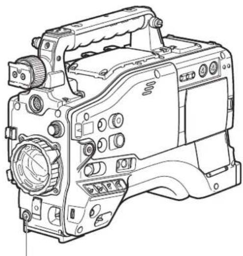
natural_image
Line drawing of a digital camera with no visible text or symbolsREC START/STOP button
Pressing the REC START/STOP button will not immediately stop data write operations to a P2 card in the following situations. And the REC START/STOP button operation is not recognized.
- When terminating a short recording
- When terminating a recording that has just continued onto a second P2 card
Variable Frame Rate (VFR) Recording
This camera takes full advantage of P2 card characteristics by providing frame skipping (undercranking) recording and high-speed (overcranking) recording without the use of a frame rate converter. (The camera must be set to 30PN, 25PN or 24PN to use these functions.) Since the camera records only the effective frames (native recording), recording time is 2 to 2.5 times longer than in the 24P, 30P and 60P modes (25P or 50P at 50 Hz) (standard recording). Like VARICAM (the AJ-HDC27 series), it also provides a recording format that can accommodate the frame rate conversion required for nonlinear editing. (The camera must be set to 30P, 25P or 24P).
Variable frame rate (VFR) recording is available only in the 720P mode.
24PN mode:
The camera recorder shoots in the 24 fps native mode. The video signals delivering images at a rate of 24 fps are recorded in 24 frames. The signals are recorded only in the effective frames so recording is possible for 2.5 times as long.
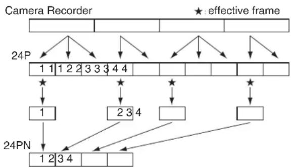
flowchart
graph TD
    A["Camera Recorder"] --> B["24P"]
    B --> C["1 1 1 2 2 3 3 3 4 4"]
    C --> D["★"]
    D --> E["1"]
    D --> F["★"]
    F --> G["2 3 4"]
    G --> H["□"]
    G --> I["□"]
    J["24PN"] --> K["1 2 3 4"]
    K --> L["□"]
    K --> M["★"]
    M --> N["□"]
    style A fill:#f9f,stroke:#333
    style J fill:#ccf,stroke:#333
    style K fill:#cfc,stroke:#333
    style L fill:#fcc,stroke:#333
    style M fill:#ffc,stroke:#333
- Before Variable Frame Rate (VFR) shooting, you must set the recording frame rate and the recording format.
-
You cannot change the frame rates while recording.
-
You can select any of 11 recording frame rates ranging from 12 frames per second (fps) to 60 fps. See [Video and Recording Formats] (page 45).
- There may be slight discrepancies between the recording frame rate displayed and the frame rate at which the images are actually recorded. Refer to the table below.
| 59.94 Hz 50 Hz | |||
| Recording frame rate displayed | Frame rate at which images are actually recorded | Recording frame rate displayed | Frame rate at which images are actually recorded |
| 60 59.94 | 50 50.00 | ||
| 48 48.17 | 48 48.08 | ||
| 36 35.68 | 37 36.75 | ||
| 32 32.11 | 32 32.14 | ||
| 30 29.97 | 30 29.76 | ||
| 26 26.44 | 27 27.17 | ||
| 24 23.98 | 25 25.00 | ||
| 22 22.48 | 23 23.15 | ||
| 20 19.55 | 20 19.74 | ||
| 18 17.98 | 18 17.86 | ||
| 12 12.26 | 12 12.50 | ||
Native recording
1 Select the 720P/30PN or 720P/24PN (720P/25PN at 50 Hz) recording format in the REC FORMAT item in the RECORDING SETUP screen.
For details on menu operation, refer to [Using the menus] (page 116).
2 Select the appropriate scene file using the SCENE FILE dial.
- If necessary, before doing this, perform the camera settings from the setting menu, and register the scene file. See [Saving scene files and other settings on SD memory cards] (page 82).
3 Using the OPERATION TYPE function on the SCENE FILE screen, select FILM CAM, and set the desired recording frame rate using the FRAME RATE function.
For details on menu operation, refer to [Using the menus] (page 116).
4 Press the REC START/STOP button.
- Pressing the REC START/STOP button starts native recording in the VFR mode.
- No signals are output from the 1394 terminal during recording or recording standby in the native mode.
- Sound is not recorded. However, sound will be recorded when the same frame rate is used for both recording and playback.
- When a recorded clip lasting a long time is to be played back and imported using a nonlinear editing system that supports Varicams, the UB MODE option on the RECORDING SETUP screen must be set to FRM.RATE.
Standard recording
1 Select the 720P/60P, 720P/30P, or 720P/24P (720P/50P, or 720P/25P at 50 Hz) recording format in the REC FORMAT item in the RECORDING SETUP screen.
For details on menu operation, refer to [Using the menus] (page 116).
2 Select the appropriate scene file using the SCENE FILE dial.
- If necessary, before doing this, perform the camera settings from the setting menu, and register the scene file.
3 Using the OPERATION TYPE function on the SCENE FILE screen, select FILM CAM, and set the desired recording frame rate using the FRAME RATE function.
For details on menu operation, refer to [Using the menus] (page 116).
- When the 720P/30P, 720P/24P, or 720P/25P recording is selected, the following indications appear depending on the settings made in the FRAME RATE item in the SCENE FILE screen.
① PULL DOWN information displayed in PROPERTY-CLIP PROPERTY-VIDEO With the default setting: 2:2 or 2:3 With any other settings: other
② Format information in the bottom left of the screen when thumbnails are displayed With the default setting: 720P/30P,
720P/24P, 720P/25P
With any other settings: 720P/60P or 720P/50P
(The default setting is 30FRAME at a recording frame rate of 30P and 24FRAME (25FRAME at 25P) at a recording frame rate of 24P.)
4 Press the REC START/STOP button.
- Pressing the REC START/STOP button starts standard recording in the VFR mode, the sound is also recorded.
- In the case of a nonlinear editing system that supports Varicams equipped with an effective frame extraction function, you can upload even undercrank or overcrank shooting materials as is. (The UB MODE option on the RECORDING SETUP screen must be set to FRM.RATE.)
- The 24P format is used for 2:3 pull-down recording and the 30P (25P at 50 Hz) is used for 2:2 pull-down recording.
Using variable frame rates (VFR)
Standard speed shooting for making commercials and dramas
When producing commercials and dramas to be shown on a TV screen, as in the case of HDTV/ SDTV and other broadcasts, a frame rate of 24 fps (frames per second) is the norm (1× speed).
If you use the settings below, the same kind of playback as when the programs are broadcast can be obtained. 720P progressive mode and cine-like gamma produce video that looks like it was shot on a film camera.
| Recording format (REC FORMAT) | Recording frame rate (FRAME RATE) |
| 720P/24P (2:3 pull-down) | 24 fps |
| 720P/24PN (native recording) |
Shooting at standard speed for producing commercials and TV programs
Production aimed at HDTV and SDTV broadcasts for TV audiences must use the full frame rate ( × 1) of 30 fps (30 frames/sec.) (25 fps at 50 Hz). Use the following settings to obtain the playback speed used for broadcasts. This permits film-like video recording of commercials and music clips that also provide a frame rate suitable for broadcasting.
| Recording format (REC FORMAT) | Recording frame rate (FRAME RATE) | |
| 59.94 Hz | 720P/30P(2:2 pull-down) | 30 fps |
| 720P/30PN(native recording) | ||
| 50 Hz | 720P/25P(2:2 pull-down) | 25 fps |
| 720P/25PN(native recording) | ||
Undercrank shooting
This way of shooting provides quick motion effects used to present such scenes as the movement of clouds, someone standing among crowd of people, and moves made by martial artists. If, for instance, you have shot scenes using the 24P recording format for specifying the playback frames, you can double the speed of the quick motion effects by setting the VFR recording frame rate to 12 fps.
| Recording format (REC FORMAT) | Recording frame rate (FRAME RATE) |
| 720P/24P, 720P/24PN Set to 22 fps or lower. | |
| 720P/30P, 720P/30PN Set to 26 fps or lower. | |
| 720P/25P, 720P/25PN Set to 23 fps or lower. | |
- The 720P/24P, 720P/30P and 720P/25P formats provide a quick motion effect when processed using a nonlinear editing system.
Overcrank shooting
This way of shooting provides slow motion effects used to show car chases as well as action scenes, climax scenes and other dramatic presentations. If, for instance, you have shot scenes using the 30P recording format for specifying the playback frames, you can obtain slow motion effects with the speed halved by setting the recording frame rate to 60 fps. Images in the 720P progressive format will create smoothly flowing slow motion sequences with a high picture quality.
| Recording format (REC FORMAT) | Recording frame rate (FRAME RATE) |
| 720P/24P, 720P/24PN Set to 26 fps or higher. | |
| 720P/30P, 720P/30PN Set to 32 fps or higher. | |
| 720P/25P, 720P/25PN Set to 27 fps or higher. | |
- The 720P/24P, 720P/30P and 720P/25P formats provide a slow motion effect when processed using a nonlinear editing system.
Shooting in the 1080i/480i Progressive Mode
Selecting 30P, 24P or 24PA (1080i or 480i mode) in the REC FORMAT in the setting menu RECORDING SETUP screen enables shooting in the progressive mode.
■30P mode
This mode enables shooting 30 fps video in the progressive mode. The 30 fps video signal is converted to a 60-field interlaced signal for output and recording.
- This guarantees high-quality video output.
30P

60i
| A | B | C | D | E | F | G | H | J | ||||
| Ao | Ae | Bo | Be | Co | Ce | Do | De | Eo | Fe | Go | Ge | Ho |
■24P mode
This mode enables shooting 24 fps video in the progressive mode. A 2:3 conversion format is used to convert the 24 fps video signal to a 60-field interlaced signal for output and recording.
- This guarantees a cine-like video output.
This mode enables shooting 24 fps video in the progressive mode.
- The advance mode converts a 24 fps video signal to a 60-field interlaced signal for output and recording.
| A | B | C | D | E | F | G | H | |
| 60i | Ao | Ae | Ba | Be | Bo | Ce | Co | De |
- As shown in the illustration, the conventional 24P (2:3) conversion system for editing extends the BoCe, CoDe, FoGe and GoHe fields into adjacent frames, which causes a drop in picture quality.
- By contrast, the 24P advance conversion system drops the BoCe and FoGe fields to produce video of higher quality. Using an editing system that is compatible with advanced conversion will help to produce better video quality than the normal 24P mode.
- Use the normal 24P mode when working with other editing systems.
The following applies to shooting in the progressive mode. - A gain of 18 dB cannot be used.
- Set the shutter speed to 1/50 (OFF) or to 1/60.
- There may be a slight delay at the start of recording when shooting in the 24P or 24P advance mode because 5 frames are recorded at a time.
Special Recording Modes
During P2 card recording, setting items in the menu option RECORDING SETUP screen provides the following special recording modes: pre-recording, interval recording, one-shot recording, and loop recording.
These recording modes are available only with the following settings.
•OPERATION TYPE item: VIDEO CAM
- Recording format:
They are available at 1080i/60i (50i), 1080i/30P (25P), 720P/60P (50P), 720P/30P (25P), or in SD at 60i (50i), 30P (25P).
Pre-recording (PRE REC)
This function is used to start recording a certain number of seconds (approx. 3 seconds for HD recordings or approx. 7 seconds for SD recordings) before actual recording starts.

flowchart
graph LR
    A["Starting recording"] --> B["Stopping recording"]
    B --> C["Actual recording time"]
    C --> D["PRE REC time"]
    style A fill:#fff,stroke:#000
    style B fill:#000,stroke:#000
    style C fill:#fff,stroke:#000
    style D fill:#fff,stroke:#000
1 Check that the OPERATION TYPE item in the menu option SCENE FILE screen and REC FORMAT item in the menu option RECORDING SETUP screen are set as described below.
For details on menu operation, refer to [Using the menus] (page 116).
• OPERATION TYPE item: VIDEO CAM
- Recording format:
They are available at 1080i/60i (50i), 1080i/30P (25P), 720P/60P (50P), 720P/30P (25P), or in SD at 60i (50i), 30P (25P).
2 Select ON in the PREREC MODE item in the menu option RECORDING SETUP screen.
3 Press the REC START/STOP button.
This setting will record audio and video a time period prior to start of recording.
- The following recording modes will disable the pre-recording function and start respective recording function when selected.
- Recording of video input via the IEEE1394 connector
- When changing recording formats
• After a change from playback to recording
• During interval recording
• During one-shot recording
• During loop recording
- Audio and video recording for the pre-recording time interval stated above may not be possible when recording is started immediately after the following changes in operating mode: after a changeover from MCR mode to CAMERA mode, after power-on, and after a change in the PREREC MODE item.
Interval recording (INTERVAL REC)
This function is used to record 1 frame (1/30 s) at the time interval set in the INTERVAL TIME item.
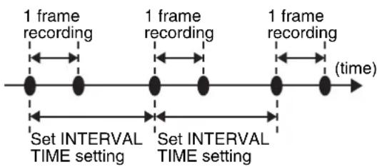
flowchart
graph LR
    A["1 frame recording"] --> B["Set INTERVAL TIME setting"]
    B --> C["1 frame recording"]
    C --> D["Set INTERVAL TIME setting"]
    D --> E["1 frame recording"]
    E --> F["(time)"]
1 Check that the OPERATION TYPE item in the menu option SCENE FILE screen and REC FORMAT item in the menu option RECORDING SETUP screen are set as described below.
For details on menu operation, refer to [Using the menus] (page 116).
• OPERATION TYPE item: VIDEO CAM
- Recording format:
They are available at 1080i/60i (50i), 1080i/30P (25P), 720P/60P (50P), 720P/30P (25P), or in SD at 60i (50i), 30P (25P).
2 Select INTERVAL in the REC FUNCTION item in the menu option RECORDING SETUP screen.
3 Set the time in the INTERVAL TIME item in the menu option RECORDING SETUP screen.
4 Press the REC START/STOP button.
- The camera will repeat 1-frame recording for the time interval set in the INTERVAL TIME item.
- Press the STOP button to stop recording.
- To cancel this function, turn the camera off or select NORMAL in the REC FUNCTION item.
- The following indications appear to the left of the operation status display.
- During recording: "I-REC" stays lit.
- During a pause: “I-PAUSE” stays lit. When a setting of less than 2 seconds is made in step 3, “I-REC” blinks according to time setting during recording.
- When stopped:"I-" in "I-PAUSE" blinks.
- The pre-recording function is not available.
• Sound is not recorded. - Data recorded (until the STOP button is pressed) in this mode is recorded as a single file.
- The 1394 connector does not output any signals.
- This function is not available if a DIR ENTRY NG CARD is inserted.
- A card inserted during recording is recognized after recording stops. Insert a card after the recording ends.
One-shot recording (ONE-SHOT REC)
This function records a single shot at each unit of time which has been set.
1 Check that the OPERATION TYPE item in the menu option SCENE FILE screen and REC FORMAT item in the menu option RECORDING SETUP screen are set as described below.
For details on menu operation, refer to [Using the menus] (page 116).
- Recording format: They are available at 1080i/60i (50i), 1080i/30P (25P), 720P/60P (50P), 720P/30P (25P), or in SD at 60i (50i), 30P (25P).
2 Select ONE SHOT in the REC FUNCTION item in the menu option RECORDING SETUP screen.
3 Set the time in the ONE SHOT TIME item in the menu option RECORDING SETUP screen.
4 Press the REC START/STOP button.
- The camera will pause recording after making a recording that lasts the duration set in step 3.
- Press the STOP button to stop recording.
- To cancel this function, turn the camera off or select NORMAL in the REC FUNCTION item.
- The following indications appear to the left of the operation status display.
- During recording: "I-REC" stays lit.
- During a pause: "I-PAUSE" stays lit.
- When stopped:"I-" in "I-PAUSE" blinks.
- No other functions are available during operation.
- The pre-recording function is not available.
• Sound is not recorded.
- Data recorded (until the STOP button is pressed) in this mode is recorded as a single file.
- The 1394 connector does not output any signals.
- This function is not available if a DIR ENTRY NG CARD is inserted.
- During continuous one-shot recording, recording operation speed may be decr
- A card inserted during recording is recognized after recording stops. Insert a card after the recording ends.
Loop recording (LOOP REC)
- When two or more P2 cards are inserted in the P2 card slots, each card is recorded in succession.
- When there is no longer any space left on the cards, recording starts over from the first card by recording new clips over saved old clips.
For the clip recording time, see [Splitting clips recorded on P2 cards] (page 32).

flowchart
graph TD
    A["Before starting loop recording"] --> B["1st card: No recording"]
    B --> C["2nd card: Recorded"]
    C --> D["3rd card: [ "]]
    E["First loop recording"] --> F["Recording start: A"]
    F --> G["Second loop recording: D"]
    G --> H["Second loop recording: B"]
    H --> I["Second loop recording: C"]
    style A fill:#f9f,stroke:#333
    style E fill:#f9f,stroke:#333
    style G fill:#f9f,stroke:#333
Recording will be made on the areas with no recording consecutively (A, B, then C). When all areas on all cards are recorded, new recording (D) will be made by overwriting the area A.
1 Check that the OPERATION TYPE item in the menu option SCENE FILE screen and REC FORMAT item in the menu option RECORDING SETUP screen are set as described below.
For details on menu operation, refer to [Using the menus] (page 116).
• OPERATION TYPE item: VIDEO CAM
- Recording format:
They are available at 1080i/60i (50i), 1080i/30P (25P), 720P/60P (50P), 720P/30P (25P), or in SD at 60i (50i), 30P (25P).
2 Select LOOP in the REC FUNCTION item in the menu option RECORDING SETUP screen.
3 Press the REC START/STOP button.
- Recording starts.
- Press the REC START/STOP button to stop recording.
- To cancel this function, turn the camera off or select NORMAL in the REC FUNCTION item.
- The following indications appear to the left of the operation status display.
- During recording: "L-REC" stays lit.
- During a pause: "L-PAUSE" stays lit.
- When remaining memory is low: "P2 LACK L-" blinks.
- Use a P2 card with at least one minute of remaining recording time.
- Switching to the mode check screen displays the minimum guaranteed recording time.
- This function is not available during IEEE1394 input.
- The pre-recording function is not available.
- This function is not available if a DIR ENTRY NG CARD is inserted.
- Canceling this function may take some time. The succeeding operations are not available until the P2 CARD ACCESS LED goes from blinking to steady lighting.
- A card inserted during recording is not used for recording.
Hot Swap Recording
With a P2 card in each card slot it is possible to make one continuous recording that spans all four cards.
And by removing any card other than that being recorded, you can make continuous recording on 5 or more cards (hot swap recording).
Note that recognition of a P2 card may be delayed depending on when it is inserted in an empty card slot (for example, immediately after pre-recording or when a recording continues from one card to the next). P2 cards should be inserted when there is still 1 minute or more time left on the card that is being recorded.
- USER MAIN/USER1/USER2 in the setting menu SW MODE screen allows you to assign the SLOT SEL function to a USER button to enable selection of a recording slot with pushbutton ease.
- Select the recording slot during standby as selecting is not available during recording.
- This function is not compatible with hot-swap playback.
Recording Check Function
- Pressing the RET button on the lens in the CAMERA mode will automatically play back the last two seconds or so of latest clip.
- Use this function to check that recording is performed normally. The camera returns to recording standby mode after playback. Playback may start from the beginning of a short clip.
- You can use the USER MAIN, USER1 and USER2 items to assign the RET button function to a USER button. Select these items from the setting menu SW MODE screen.
Note that the playback during recording check will be recorded on a backup device connected to the IEEE1394 or SDI OUT connector.
Shot Marker (SHOT MARK) Recording Function
This function can be used to distinguish a clip from other clips by adding a thumbnail to each clip.
This also makes possible to display or play back the marked clips only.
To add shot marks
1 In the setting menu SW MODE screen, assign SHOT MARK to a USER button (USER MAIN, USER1 or USER2).
For details on menu operation, refer to [Using the menus] (page 116).
2 During recording, press the USER button to which the SHOT MARK function has been assigned.
- “MARK ON” is displayed as a shot mark is inserted in the currently recorded clip.
- Pressing this key a second time displays "MARK OFF" and the shot mark is deleted.
- Shot marks can be added also in the thumbnail display.
- The shot marker function is not available during loop recording. When this function is not available, pressing this button displays "INVALID".
- Shot marks cannot be set or deleted during playback.
- Shot marks for video data created in a single hot-swap recording session consisting of multiple clips cannot be set or deleted unless all the P2 cards that contain the video data for the entire session are inserted.
Text Memo Recording Function
Text memo allows the user to insert a text memo with time code at any point during clip recording and playback.
This makes it possible to display only the thumbnails of the clips with text memos, or to display thumbnails and time codes of the text memo positions in order.
To add text memos
1 Use the setting menu SW MODE screen to assign the TEXT MEMO function to a USER button.
For details on menu operation, refer to [Using the menus] (page 116).
2 During recording or playback, press the USER button to which the TEXT MEMO has been assigned.
- "TEXT MEMO" is displayed and a text memo is inserted at the point the button is pressed.
- You can insert up to 100 text memos per clip.
- The text memo function is not available during loop recording, interval recording and one-shot recording. When this function is not available, pressing this button displays "INVALID".
Normal and Variable Speed Playback
■Normal speed playback
Clips can be played back in the MCR mode. The PLAY button provides monochrome playback through the viewfinder and color playback on the LCD monitor. Connecting a color video monitor to the VIDEO OUT connector, SDI OUT connector and COMPONENT OUT connector at the same time will enable viewing of the playback video in color.
■Fast-forward/fast-reverse playback
The FF and REW buttons provide 32× and 4× fast playbacks and fast reverse playbacks. In stop mode, this function will play back video at 32× speed and in playback mode, it will play back video at 4× speed.
Clip cue up
When playback is paused, the FF button locates the beginning of the next clip while maintaining the pause mode.
When playback is paused, the REW button locates the beginning of the current clip while maintaining the pause mode.
- When a P2 card has just been removed or inserted or the MCR mode has just been engaged after turning on the power, it may take some time for the camera to read clip information. If this is the case, the thumbnail screen displays "UPDATING".
- If a P2 card is inserted while another P2 card is being played back, the clips on the inserted P2 card will not be played back. A P2 card inserted during playback will be recognised after playback ends.
- If you perform variable speed playback on a clip split across more than one P2 card, sound may disappear for a moment. This is not a fault.
- To play back a clip in a format that differs from REC FORMAT, set MCR FORMAT on the setting menu RECORDING SETUP screen to the format of the clip to be played back.
- Playback of the audio channels CH5 to CH8 recorded on another device is not possible.
■Variable speed search
Pressing the PLAY button during playback starts variable playback search at 1× speed.
In this mode, the PAGE/VAR button provides the following playback speeds:
- -24x, -12x, -4x, -2x, -1x, -1/5x, 1/5x, 1x, 2x, 4x, 12x, 24x
Pressing the PLAY button returns the camera to normal playback.
■Frame-by-frame playback
In playback pause mode, the PAGE/VAR button provides frame-by-frame playback.
Frame-by-frame playback is performed at the following increments:
• 720P: 1/60 or 1/50 increments
- 720P/24PN, 30PN, 25PN: 1/24, 1/30, 1/25 increments
• 1080i, 480i, 576i: 1/30 or 1/25 increments
Video and recording formats
Multiple HD/SD formats
This unit supports recordings in 20 HD and SD video formats. 1080i/720p HD recording uses the DVCPRO HD codec, while SD recording is performed in DVCPRO50 / DVCPRO/DV multi-codec.
■ Video formats and codecs supported by this camera
| Video format *1 | Recording time *3 | Recording codec | |
| HD59.94 Hz | 1080/60i | 64 minutes | DVCPRO HD |
| 1080/30P (over 60i) | |||
| 1080/24P (over 60i) | |||
| 1080/24PA (over 60i) | |||
| 720/60P | |||
| 720/30P (over 60P) | |||
| 720/24P (over 60P) | |||
| 720/30PN (Native)*2 | 128 minutes | ||
| 720/24PN (Native)*2 | 160 minutes | ||
| HD50 Hz | 1080/50i | 64 minutes | |
| 1080/25P (over 50i) | |||
| 720/50P | |||
| 720/25P (over 50P) | |||
| 720/25PN (Native)*2 | 128 minutes | ||
| SD59.94 Hz | 480/60i | 128 minutes (DVCPRO 50)256 minutes (DVCPRO/DV) | |
| 480/30P (over 60i) | |||
| 480/24P (over 60i) | |||
| 480/24PA (over 60i) | |||
| SD50 Hz | 576/50i | ||
| 576/25P (over50i) | |||
*1 24P and 30P indicate recording at 23.98P and 29.97P, respectively, while 60P and 60i indicate recording at 59.94P and 59.94i, respectively.
*2 Native mode is a mode that records only effective frames.
*3 The listed recording times are for four 16 GB P2 cards. Using only one 16 GB card will reduce the recording time to 1/4. In addition to the video format and codec, function setup and the number of cuts will affect the recording time.
Selecting recording signals in CAMERA MODE
CAMERA MODE allows you to record video shot with the camera.
Use the setting menus listed below to select recording signals.
| Setting menu Setting | |
| SYSTEM FREQ (OTHER FUNCTIONS screen) | Set system frequency (59.94 Hz, 50 Hz). When this setting is changed, wait for the “TURN POWER OFF” message to appear to turn the power off and then turn it back on again. |
| REC FORMAT (RECORDING SETUP screen) | ● Select formats and frame rates for recording and capture. ● Select combinations of recording formats (1080i, 720P, 480i/576i) and frame rates (60P/50P, 60i/50i, 30P/25P, 24P, 24PA). ● 720P/30PN, 24PN and 25PN are native recording formats. |
| FRAME RATE (SCENE FILE screen) | Setting FILM CAM in the setting menu OPERATION TYPE (SCENE FILE screen) makes it possible to select the 720P mode capture frame rate. For details, see [Variable Frame Rate (VFR) Recording] (page 37). |
| 480i (576i) REC MODE (RECORDING SETUP screen) | In SD mode (480i, 576i) you can select DVCPRO50 or DVCPRO/DV recording mode. |
| ASPECT CONV (CAMERA SETUP screen) | In SD mode (480i, 576i), select the aspect ratio for video. |
Selecting MCR mode recording and playback signals
MCR mode allows you to record signals from the 1394 connector and play back P2 card clips. Use the setting menus listed below to select recording or playback signals.
| Setting menu Setting | |
| SYSTEM FREQ (OTHER FUNCTIONS screen) | Set system frequency. (59.94 Hz, 50 Hz) When this setting is changed, wait for the “TURN POWER OFF” message to appear to turn the power off and then turn it back on again. |
| MCR FORMAT (RECORDING SETUP screen) | ● Select the format for recording signals input to the 1394 connector or format for playing back P2 card clips. ● Recording and playback of 1080i, 720P and 480i/576i are possible. ● 720P/30PN, 720P/24PN and 720P/25PN enable playback of clips recorded at respective native frame rate. ● In a change from CAMERA MODE to MCR mode, the REC FORMAT recording format is retained. |
| 480i (576i) MCR MODE (RECORDING SETUP screen) | ● In SD mode (480i, 576i), you can select DVCPRO50 or DVCPRO/DV for recording 1394 connector signals or as playback mode to play back P2 card clips. ● In a change from CAMERA mode to MCR mode, the 480i (576i) REC MODE is retained. |
Selecting video output
CAMERA MODE and MCR mode allow you to select video output format.
Use the setting menus listed below to select video output.
| Setting menu Setting | |
| CMPNT/SDI SEL(OUTPUT SEL screen) | Select the signal format(AUTO, 1080i, 480i/576i)to be output from theCOMPONENT OUTconnector and SDI OUTconnector. |
| SETUP(CAMERA SETUP screen)• 59.94 Hz system | Select the setup level for the480i video signal.● 0%: Setup 0% also foroutput and recording● 7.5%A: 7.5% setup levelfor output only (0% forrecording)The SETUP menu settingis enabled also during playback. |
| DOWNCON MODE(DISPLAY SETUP screen) | Select the screen type tobe output (COMPONENTOUT, SDI OUT when VIDEOOUT and CMPNT/SDI SELis down converted to 480i or576i) and down-converted inHD mode (1080i, 720P). |
The audio and video may be disturbed when the REC FORMAT and MCR FORMAT is changed in the setting menu SYSTEM FREQ, but this is not a camera malfunction.
List of recording, playback and output formats
CAMERA mode (recording)
■SYSTEM FREQ (setting menu): 59.94 Hz
| Format setting | Recording status | Output setting | Output status | ||||||
| REC FORMAT | Capture and recording frame rate | Recording format | Audio recording channels | CMPNT/ SDI SEL | SDI OUT | SDI OUT AUDIO | COMPONENT OUT | VIDEO OUT | 1394 output |
| 1080i/ 60i | 60i | DVCPRO HD 1080i/59.94i | 4ch | AUTO | 1080i/ 59.94i | 4ch | 1080i/59.94i | 525i/ 59.94i | DVCPRO HD 1080i/59.94i |
| 1080i/ 30P | 30P over 60i | 1080i | 1080i/ 59.94i | 1080i/59.94i | |||||
| 1080i/ 24P | 24P over 60i | 480i | 525i/ 59.94i | 525i/59.94i | |||||
| 1080i/ 24PA | 24PA over 60i | ||||||||
| 720P/ 60P | 60P*1 | DVCPRO HD 720P/59.94P | 4ch | AUTO | 720P/ 59.94P*1 | 4ch | 720P/59.94P*1 | 525i/ 59.94i | DVCPRO HD 720P/59.94P*1 |
| 720P/ 30P | 30P over 60i*1 | 1080i | 1080i/ 59.94i | 1080i/59.94i | |||||
| 720P/ 24P | 24P over 60i*1 | 480i | 525i/ 59.94i | 525i/59.94i | |||||
| 720P/ 30PN | 30P native recording at 30P capture*2 | DVCPRO HD 720P/29.97P | 4ch*5 | AUTO | 720P/ 59.94P*1 | 4ch*5 | 720P/59.94P*1 | 525i/ 59.94i | No output |
| 720P/ 24PN | 24P native recording at 24P capture*3 | DVCPRO HD 720P/23.98P | 1080i | 1080i/ 59.94i | 1080i/59.94i | ||||
| 480i | 525i/ 59.94i | 525i/59.94i | |||||||
| 480i/ 60i | 60i | DVCPRO50, DVCPRO/DV*4 480i/59.94i | 4CH or 2CH*6 | Disabled | 525i/ 59.94i | 4CH or 2CH*6 | 525i/59.94i | 525i/ 59.94i | DVCPRO50, DVCPRO/DV*4 525i/59.94i |
| 480i/ 30P | 30P over 60i | ||||||||
| 480i/ 24P | 24P over 60i | ||||||||
| 480i/ 24PA | 24PA over 60i | ||||||||
* In FILM CAM mode, this means 12P to 60P capture over 60P depending on FRAME RATE menu setting.
^*2 In FILM CAM mode, this means VFR recording at 12P to 60P capture depending on FRAME RATE menu setting. ( playback at 30P over 60P)
*3 In FILM CAM mode, this means VFR recording at 12P to 60P capture depending on FRAME RATE menu setting. (Playback at 24P over 60P)
*4 Select DVCPRO50 or DVCPRO/DV according to 480i (576i) REC MODE.
*5 Audio is not recorded or output unless the FRAME RATE is set to DEFAULT or 30FRAME in 720P/30P. Audio is not recorded or output unless the FRAME RATE is set to DEFAULT or 24FRAME in 720P/24P.
*6 In the 25M REC CH SEL menu, select 4CH for DVCPRO50 mode and 2H/4CH in DVCPRO/DV mode.
■SYSTEM FREQ (setting menu): 50 Hz
| Format setting | Recording status | Output setting | Output status | ||||||
| REC FORMAT | Capture and recording frame rate | Recording format | Audio recording channels | CMPNT/ SDI SEL | SDI OUT | SDI OUT AUDIO | COMPONENT OUT | VIDEO OUT | 1394 output |
| 1080i/ 50i | 50i | DVCPRO HD 1080i/50i | 4ch | AUTO | 1080i/ 50i | 4ch | 1080i/50i | 625i/ 50i | DVCPRO HD 1080i/50i |
| 1080i/ 25P | 25P over 50i | 1080i | 1080i/ 50i | 1080i/50i | |||||
| 576i | 625i/ 50i | 625i/50i | |||||||
| 720P/ 50P | 50P^*7 | DVCPRO HD 720P/50P | 4ch | AUTO | 720P/ 50P^*7 | 4ch | 720P/50P^*7 | 625i/ 50i | DVCPRO HD 720P/50P^*7 |
| 720P/ 25P | 25P over 50P^*7 | 1080i | 1080i/ 50i | 1080i/50i | |||||
| 576i | 625i/ 50i | 625i/50i | |||||||
| 720P/ 25PN | 25P native recording at 25P capture^*8 | DVCPRO HD 720P/25P | 4ch^*3 | AUTO | 720P/ 50P^*7 | 4ch^*3 | 720P/50P^*7 | 625i/ 50i | No output1080 |
| 1080i/ 50i | 1080i/50i | ||||||||
| 576i | 625i/ 50i | 625i/50i | |||||||
| 576i/ 50i | 60i | DVCPRO50, DVCPRO/DV ^*4 625i/50i | 4CH or 2CH^*6 | Disabled | 625i/ 50i | 4CH or 2CH^*6 | 625i/50i | 625i/ 50i | DVCPRO50, DVCPRO/DV ^*4 625i/50i |
| 576i/ 25P | 25P over 50i | ||||||||
*4 Select DVCPRO50 or DVCPRO/DV according to 480i (576i) REC MODE.
*5 In the 25M REC CH SEL menu, select 4CH for DVCPRO50 mode and 2H/4CH in DVCPRO/DV mode.
*7 In FILM CAM mode, this means 12P to 50P capture depending on FRAME RATE menu setting.
*8 In FILM CAM mode, this means VFR recording at 12P to 50P capture depending on FRAME RATE menu setting. (Playback at 25P over 50P)
*9 Audio is not recorded or output unless the FRAME RATE is set to DEFAULT or 25FRAME in 720P/25PN.
MCR mode (playback and recording of 1394 input)
■SYSTEM FREQ (setting menu): 59.94 Hz
| Format setting | Recording status | Output setting | Output status | |||||
| MCR FORMAT | 1394 recording and playback format | Recording and playback audio channel | CMPNT/SDI SEL | SDI OUT | SDI OUT AUDIO | COMPONENT OUT | VIDEO OUT | Playback of 1394 output |
| 1080i/60i | DVCPRO HD 1080i/59.94i | 4ch | AUTO | 1080i/59.94i | 4ch | 1080i/59.94i | 525i/59.94i | DVCPRO HD 1080i/59.94i |
| 1080i | 1080i/59.94i | 1080i/59.94i | ||||||
| 480i | 525i/59.94i | 525i/59.94i | ||||||
| 720P/60P | DVCPRO HD 720P/59.94P | 4ch | AUTO | 720P/59.94P | 4ch | 720P/59.94P | 525i/59.94i | DVCPRO HD 720P/59.94P |
| 1080i | 1080i/59.94i | 1080i/59.94i | ||||||
| 480i | 525i/59.94i | 525i/59.94i | ||||||
| 720P/30PN | DVCPRO HD 720P/59.94P*1*2 | 4ch^*5 | AUTO | 720P/59.94P*1*2 | 4ch^*5 | 720P/59.94P*1*2 | 525i/59.94i*1 | DVCPRO HD 720P/59.94P*2 |
| 1080i | 1080i/59.94i* | 1080i/59.94i*1 | ||||||
| 480i | 525i/59.94i* | 525i/59.94i*1 | ||||||
| 720P/24PN | DVCPRO HD 720P/59.94P*1*3 | 4ch^*5 | AUTO | 720P/59.94P*1*3 | 4ch^*5 | 720P/59.94P*1*3 | 525i/59.94i*1 | DVCPRO HD 720P/59.94P*2 |
| 1080i | 1080i/59.94i* | 1080i/59.94i*1 | ||||||
| 480i | 525i/59.94i* | 525i/59.94i*1 | ||||||
| 480i/60i | DVCPRO50, DVCPRO/DV*525i/59.94i | 4CH, or 2CH *? | Disabled | 525i/59.94i | 4CH, or 2CH *? | 525i/59.94i | 525i/59.94i | DVCPRO50, DVCPRO/DV*525i/59.94i |
■SYSTEM FREQ (setting menu): 50 Hz
| Format setting | Recording status | Output setting | Output status | |||||
| MCR FORMAT | 1394 recording and playback format | Recording and playback audio channel | CMPNT/SDI SEL | SDI OUT | SDI OUT AUDIO | COMPONENT OUT | VIDEO OUT | Playback of 1394 output |
| 1080i/50i | DVCPRO HD 1080i/50i | 4ch | AUTO 1080i/50i | 4ch | 1080i/50i | 625i/50i | DVCPRO HD 1080i/50i | |
| 1080i 1080i/50i 1080i/50i | ||||||||
| 576i 625i/50i 625i/50i | ||||||||
| 720P/50P | DVCPRO HD 720P/50P | 4ch | AUTO 720P/50P | 4ch | 720P/50P | 625i/50i | DVCPRO HD 720P/50P | |
| 1080i 1080i/50i 1080i/50i | ||||||||
| 576i 625i/50i 625i/50i | ||||||||
| 720P/25PN | DVCPRO HD 720P/25P*1*4 | 4ch*5 | AUTO 720P/50P*1*4 | 4ch*5 | 720P/50P*1*4 | 625i/50i*1 | DVCPRO HD 720P/50P*4 | |
| 1080i 1080i/50i*1 | 1080i/50i*1 | |||||||
| 576i 625i/50i*1 | 625i/50i*1 | |||||||
| 576i/50i | DVCPRO50, DVCPRO/DV*625i/50i | 4CH, or 2CH*7 | Disabled 625i/50i | 4CH, or 2CH*7 | 625i/50i | 625i/50i | DVCPRO50, DVCPRO/DV*625i/50i | |
^*1 1394 input cannot be recorded and the output produces a black screen.
^*2 Playback is converted to over 60P using a 2:2 pulldown.
*3 Playback is converted to over 60P using a 2:3 pulldown.
*4 Playback is converted to over 50P using a 2:2 pulldown.
*5 Clips recorded without sound are played back without sound.
*6 Format will be any of DVCPRO50 or DVCPRO/DV, depending on 480i (576i) MCR mode.
*7 4CH for DVCPRO50, and 2CH or 4CH for DVCPRO/DV.
Adjusting the White balance and Black Balance
To record high-quality video with the AG-HPX500P/E, the black and white balances must be adjusted according to conditions.
For higher quality, it is recommended that the adjustments should be made in this order AWB (white balance adjustment) → ABB (black balance adjustment) → AWB (white balance adjustment).
Adjusting the White Balance
Whenever light conditions change, the white balance must be readjusted.
To adjust the white balance, follow the steps below.

1 ND FILTER control
This control adjusts the amount of light entering the CCD.
2 AUTO W/B BAL switch
Use for automatic control of white balance.
3 GAIN selector switch
Normally set to 0 dB. If this is too dark, adjust gain as necessary.
4 OUTPUT selector switch
Set to CAM.
5 WHITE BAL switch
Set to A or B.
1 Set the GAIN, OUTPUT and WHITE BAL switches.
2 Adjust the ND FILTER control according to the light conditions.
For examples of ND FILTER adjustments, see [Shooting and Recording/Playback Functions Section] (page 19).
3 Place a white pattern at a point where the light conditions match those for the light source of the subject. Then zoom-in on the white pattern so that white colour appears in the screen.
- A white object (cloth or wall) may be used instead of a white pattern. The illustration below shows the required size for the white space.
- Do not include a high-intensity spot in the screen.
- The white object must appear at the center of the screen.
1/4 or more of the screen in width

4 Adjust the lens iris.
- Display the center marker and adjust the iris to obtain a 70% indication.
5 Turn the AUTO W/B BAL switch toward [AWB] and release it.
- The switch returns to the central position with the white balance automatically adjusted.
6 During an adjustment, the viewfinder displays the following message:
AWB Ach ACTIVE
7 The adjustment will take effect in a few seconds, and the following message will appear:
- The adjusted value is automatically stored in the selected memory (A or B).
AWB Ach OK 3.2K
- "C TEMP+7" to "C TEMP-7" will appear when COLOR TEMP of the scene file is set to the value other than 0.
8 If the subject's colour temperature is lower than 2300K or higher than 9900K the following message appears:
- If the arrow points down (↓) the actual colour temperature is lower than the temperature indicated. If the arrow points up (↑) the actual temperature is higher than the temperature indicated.
AWB Ach OK 2.3K ↓
When you have no time to adjust the white balance
Position the WHITE BAL switch at [PRST].
- Turning the AUTO W/B BAL switch to AWB toggles the color temperature between 3200K and 5600K.
When the white balance has not been automatically adjusted
When the white balance has not been successfully adjusted, the viewfinder displays an error message.
| Error message Description | |
| AWB NG | The color temperature is too high or too low. |
| LOW LIGHT There is insufficient light. | |
| LEVEL OVER There is too much light. | |
Viewfinder displays related to white balance
See [Viewfinder Screen Status Displays] (page 67).
Adjusting the Black Balance
The black balance must be adjusted when:
- You use your AG-HPX500P/E the first time.
- Your AG-HPX500P/E has not been used for some time.
- The ambient temperature has changed substantially.
• The gain switchover value has been changed.

1 AUTO W/B BAL switch
Use for automatic control of white balance.
2 OUTPUT selector switch
Set to CAM.
1 Tilt the AUTO W/B BAL switch so that it is positioned at [ABB], then release it.
- The switch returns to the central position with the black balance automatically adjusted.
2 During adjustment, the viewfinder displays the following message:
3 The adjustment will take effect in a few seconds and the following message will appear:
ABB END
- The adjusted value is automatically stored in the memory.
- Ensure that the lens connector is connected and the lens iris is CLOSE.
- During a black balance adjustment, light is automatically cut off.
Retaining black balances
Each value in memory is retained even if the video camera-recorder is turned off.
Setting the Electronic Shutter
Setting the Shutter Mode and Speed
1 Press the SHUTTER switch positioned at OFF towards ON.

natural_image
Line drawing of a digital camera with no visible text or symbolsSHUTTER switch
2 Press the SHUTTER switch towards [SEL]. Repeat this switchover until the desired mode or speed appears in the viewfinder screen.
- If all modes and speeds are available, the display changes in the following order:
60 Hz mode
For 60i and 60P recording

For 30P recording

For 24P recording (excluding 720P/24P and 720P/24PN)

For 24P recording (at 720P/24P or 720P/24PN)

50 Hz mode
For 50i and 50P recording

For 25P recording

- In any electronic shutter mode, a slower shutter speed will reduce camera sensitivity.
- In auto iris mode, a faster shutter speed will increase the aperture and lower the depth of field.
- When OPERATION TYPE on the setting menu SCENE FILE screen is set to FILM CAM, the shutter speed indication in ( ) does not change.
Viewfinder displays relating to the shutter
See [Viewfinder Screen Status Displays] (page 67).
Placing the Camera-recorder in SYNCHRO SCAN Mode
To place the camera-recorder in SYNCHRO SCAN mode, follow the steps below.
1 Press the SHUTTER switch positioned at [ON] towards [SEL], to place the camera-recorder in SYNCHRO SCAN (S/S) mode.
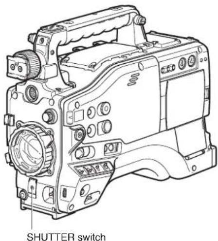
2 In SYNCHRO SCAN mode, the speed can be switched seamlessly between 1/60.0 and 1/249.8 seconds, using the JOG dial button. (Speed switchover is enabled in 60i mode.)
Range of variation in each mode
■59.94 Hz mode
• 60P/60i mode: 1/60.0 to 1/249.8
• 30P/30PN mode: 1/30.0 to 1/249.8
• 24P/24PA/24PN mode: 1/24.0 to 1/249.8
• FILM CAM mode*: 10.0d to 360.0d
■50 Hz mode
- 50P/50i mode: 1/50.0 to 1/248.9
• 25P/25PN mode: 1/25.0 to 1/248.9
• FILM CAM mode*: 10.0d to 360.0d
* Setting FILM CAM in the OPERATION TYPE item in the setting menu SCENE FILE screen enables setting and display in opening.
Assigning functions to USER buttons
The USER MAIN, USER1, and USER2 buttons can be assigned user-selected functions.
Use the menu options USER MAIN, USER1, and USER2 to assign functions to respective button. Select these items from the setting menu SW MODE screen.

Selectable Functions
• REC CHECK: Assigns recording check.
- SPOTLIGHT: Assigns auto iris control on/off for spotlight.
- BACKLIGHT: Assigns auto iris control for backlight compensation.
- BLACKFADE: Assigns blackfade.
- WHITEFADE: Assigns whitefade.
• GAIN 18dB: Assigns a gain increase of 18 dB.
- TEXT MEMO: Assigns text memo recording.
- SLOT SEL: Assigns P2 card slot selection.
- SHOT MARK: Assigns shot marker function.
- LVL METER: Assigns channel level indicator function.
- MARKER: Assigns the center marker indicator function.
- LCD REV: Assigns the function that flips the LCD image vertically and horizontally.
The default settings are listed below.
USER MAIN: SHOT MARK
USER1: BACK LIGHT
USER2: LVL METER
Selecting Audio Input Signals and Adjusting Recording Levels
This AG-HPX500P/E supports independent four-channel audio recording in any format (HD or SD). When the AUDIO SELECT CH1/CH2 switch is positioned at [AUTO], the recording levels for Audio Channels 1 and 2 are automatically adjusted. To manually adjust the recording levels, position the switch at [MAN].
Note that the recording levels for Audio Channels 3 and 4 are selected through a menu option.
Selecting Audio Input Signals
The input signals to be recorded on Audio Channels 1, 2, 3, and 4 are selected with the AUDIO IN switch. For more information, see [Audio (input) Function Section] (page 16).
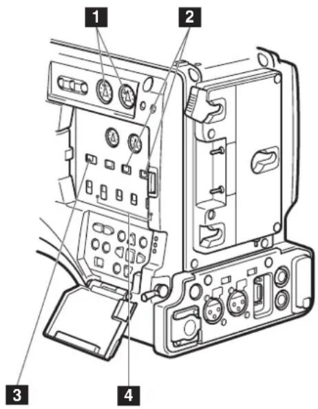
1 AUDIO LEVEL CH1/CH2 controls
2 AUDIO SELECT CH1/CH2 switch
3 MONITOR SELECT CH1/3 / ST / CH2/4 selector switch
4 AUDIO IN switch
Your AG-HPX500P/E is factory-set to perform no recording on Audio Channels 3 and 4 in the DVCPRO and DV formats. To enable four-channel recording, the menu option 25M REC CH SEL on the AUDIO SETUP screen must be set to 4CH.
For details on switch settings and the input system, see [AUDIO IN switch] (page 16).
- The audio signals recorded on the four channels are output as is (SDI).
- With a front microphone (such as AG-MC200G) connected, setting CH1 of the AUDIO IN switch to FRONT2, setting CH2-CH4 to FRONT and setting the MONITOR SELECT CH1/2 / CH3/4 selector switch to CH3 or CH4 will result in no sound output to CH3.
Use the AUDIO SETUP screen in the setting menu to make detailed audio settings.
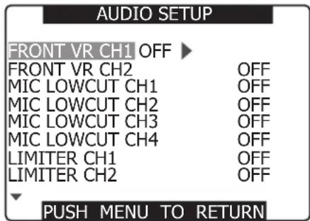
Adjusting Recording Levels
To adjust the recording levels for Audio Channels 1 and 2, follow the steps below.
1 Position the MONITOR SELECT CH1/2 / CH3/4-selector switch at CH1/2 so that the audio level meter on the display window will provide CH1 and CH2 indications. Ensure that the channel indications displayed in the window are 1 and 2.
2 Position the AUDIO SELECT CH1/CH2 switch at [MAN].
3
While checking the audio channel level meter in the display window or the audio level meter in the viewfinder, adjust the AUDIO LEVEL CH1/CH2 control.
- Note that if the level exceeds the top bar (0 dB), the word OVER illuminates to show that the input level is excessive. The adjustment made in such a way that the maximum level will not reach the 0 dB bar.

When operating the AG-HPX500P/E without a sound recordist, it is recommended that the FRONT AUDIO LEVEL control should be used to adjust the audio level.
In advance, check the level meter in the viewfinder screen and use the FRONT AUDIO LEVEL control to adjust the appropriate audio channel so that no excessive audio signals will be admitted.
Selecting Function for the FRONT AUDIO LEVEL Control
Use the menu options FRONT VR CH1 and FRONT VR CH2 to determine whether or not to enable control of selected input signals using the FRONT AUDIO LEVEL control. Selecting the ON setting enables FRONT AUDIO LEVEL control operation. Select these items from the setting menu AUDIO SETUP screen.
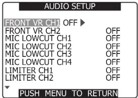
CH3 and CH4 Recording Levels
Set the menu options AUTO LEVEL CH3 and AUTO LEVEL CH4 in the AUDIO SETUP screen of the setting menu to OFF to adjust the recording level with the AUDIO LEVEL CH3 and CH4 controls.
Setting Time Data
This camera records time data such as the time code, user bits, date and time (real time) data in the subcode area, VIDEO AUX area and in clip meta data files.
Time data overview
Time code
Use the TCG switch to select Rec Run or Free Run mode.
- Free Run: The time code advances constantly whether the camera is on or not just like time itself. Recording using a slave-locked time code input to the TC IN or 1394 connectors is also possible.
- Rec Run: The time code advances only during recording. This will enable continuation of time codes in previously recorded clips and when the power is turned off or new P2 cards are inserted to continue recording.
The following events will disrupt time code continuity. - When clips are deleted
- When a 24P or 24PA frame rate is selected
- When 24PN, 30PN or 25PN is selected
- When a recording is interrupted by a REC WARNING or other abnormality
User bits
- There are two types of user bits. The user bits (UB) that are recorded in the subcode area and the user bits (VITC UB) that are recorded in the VIDEO AUX area.
- The subcode user bits enable the recording of user settings, time, date, time code and similar values, the frame rate data for camera capture, external input values (via TC IN or 1394 connector input).
- VITC user bits record the frame rate data of camera capture.
- The clip meta data user bit records the user bit values in the subcode area at start of recording.
■Date (real time)
- The built-in clock calculates the year, month, day and time from the internal clock to display on video in the LCD, viewfinder and VIDEO OUT and other video output.
- The internal clock is not only used to calculate the free run time code when the power is off and to set the user bit year, date and time, but also to set file creation dates when clips are recorded that determine the order of thumbnails and playback order.
- It is also used to generate clip meta data and UMID in the VIDEO AUX area. For details, see [Setting Date and Time of Internal Clock] (page 28).
Recording time codes and user bits
These values are recorded as listed below depending on system frequency and recording format.
| MODE. SYSTEM FREQ | REC MODE/ MCR MODE | FRAME RATE (FILM CAM) | Subcode area time code | VIDEO AUX area time code (VITC) | Recorded time code frames | Output time code frames | Displayed time code frames | Subcode area user bits | VIDEO AUX area user bits (VITC UB) |
| 59.94 Hz CAMERA mode | 1080i/60i 1080i/30P | Not related | Depends on time code mode*1 | Depends on time code mode*1 | 30 30 | 30/24 switchable *7 | Depends on user bits mode*4 | Locked to frame rate data | |
| 1080i/24P 1080i24PA | Not related | Locked to non-drop frame rate*2 | Locked to non-drop frame rate*2 | 30 30 | 30/24 switchable *7 | ||||
| 720P/60P 720P/30P 720P/24P | 12P to 60P (except at 24P) | Depends on time code mode*1 | Depends on time code mode*1 | 30 30 | 30/24 switchable *7 | Depends on user bits mode*4 | Locked to frame rate data | ||
| 24P | Locked to non-drop frame rate*2 | Locked to non-drop frame rate*2 | 30 30 | 30/24 switchable *7 | |||||
| 720P/30PN | 12P to 60P | Depends on time code mode*1*6 | Depends on time code mode*1*6 | 30 30 | Locked at 30 | Depends on user bits mode*4 | Locked to frame rate data | ||
| 720P/24PN | 12P to 60P | Locked to non-drop frame rate*2*6 | Locked to non-drop frame rate*2*6 | 24 30 | Locked at 24 | ||||
| 480i/60i 480i/30P | Not related | Depends on time code mode*1 | Depends on time code mode*1 | 30 30 | 30/24 switchable *7 | Depends on user bits mode*4 | Locked to frame rate data | ||
| 480i/24P 480i/24PA | Not related | Locked to non-drop frame rate*2 | Locked to non-drop frame rate*2 | 30 30 | 30/24 switchable *7 | ||||
| 59.94 Hz MCR mode (recording of 1394 input) | 1080i/60i 720P/60P 480i/60i | Not related | Depends on time code mode*3 | Records VIDEO AUX area time code input via 1394 regardless of setting | 30 30 | 30/24 switchable *7 | Depends on user bits mode*5 | Records VIDEO AUX area user bits input via 1394 regardless of setting | |
| 720P/30PN | Not related | Not recorded (Playback 30: frame) | Not recorded (Playback 30: frame) | — | —(Playback: 30) | —(Playback: locked at 30) | Not recorded | Not recorded ( playback: frame rate data is converted and generated in synch with video pull-down) | |
| 720P/24PN | Not related | Not recorded ( playback 30: frame) | Not recorded ( playback 30: frame) | — | —(Playback: 30) | —(Playback*8: 30/24 switchable) | |||
| 50 Hz CAMERA mode | 1080i/50i 1080i/25P | Not related | *1 *1 | 25 25 | Locked at 25 | Depends on user bits mode*4 | Locked to frame rate data | ||
| 720P/50P 720P/25P | 12P to 50P | ||||||||
| 720P/25PN | 12P to 50P | *1*6 *1*6 | |||||||
| 576i/50i 576i/25P | Not related | *1 *1 | |||||||
| 50 Hz MCR mode (recording of 1394 input) | 1080i/50i 720P/50P 576i/50i | Not related | *3 | Records VIDEO AUX area time code input via 1394 regardless of setting | 25 25 | Locked at 25 | Depends on user bits mode*5 | Records VIDEO AUX area user bits input via 1394 regardless of setting | |
| 720P25PN | Not related | Not recorded N | Not recorded | — | —(Playback: 25) | —(Playback: 25) | Not recorded | Not recorded ( playback: frame rate data is converted and generated in synch with video pull-down) |
*1 In Free Run mode, slaved to time code input to the TC IN connector.
*2 In Free Run mode, slaved to non-drop frame time code input to the TC IN connector.
*3 Setting F-RUN TC SAVE to 1394 in Free Run mode slaves it to the input from the 1394 connector, not to the TC IN connector input.
* Setting TC IN UB REGEN to ON in the setting menu slaves it to user bits input to the TC IN connector.
*5 Setting 1394 UB REGEN to ON in the setting menu slaves it to user bits input to the 1394 connector.
*6 Should the set capture frame rate differ from the recording frame rate, it is locked to Rec Run (not slaved)
*7 Only in FILM CAM mode. In VIDEO CAM mode, it is locked at 30 frames.
*8 Only in FILM CAM mode. In VIDEO CAM mode, it is locked at 24 frames.
Setting user bits
Use the setting menu UB MODE on the RECORDING SETUP screen to select the user bits to record in the subcode area.
- USER
Records internal user values.
To set user values, set the TCG switch to SET to open the setting menu TC PRESET screen.
Set values are retained after the power is turned off. See also [Entering the User Bits] (page 60).
• TIME
Records the time calculated by the internal clock.
• DATE
Records the year, month and day time digits from the internal clock.
• TCG
Records the time code value.
• FRM. RATE
Records the frame rate information of camera capture.
A natively recorded clip is output at the same frame rate as the user bit in the VIDEO AUX area regardless of recorded values. Use this setting when a PC or other editing device is to use the user bit frame rate.
For details, see [Frame Rate Information Recorded in User Bits] (page 61).
- To slave lock to user bit input to the TC IN connector, set the setting menu TC IN UB REGEN on the RECORDING SETUP screen to ON.
- To slave lock to user bit input to the 1394 connector during recording of input from the 1394 connector in MCR MODE, set the setting menu 1394 UB REGEN to ON.
- In slave mode, the UB indicator is highlighted. In this status, the UB MODE setting is disabled.
-
A slave relationship, once started, continues even after input from the TC IN or 1394 connector ends. However, the following events release a user bit slave status.
-
When the setting menu TC IN UB REGEN or 1394 UB REGEN is set to OFF.
• UB PRESET is performed
• CAMERA/MCR mode switching
• The power is turned off
The internal user value retains the slave values even after slave release.
Entering the User Bits
The user bits allow information, including memos that use up to eight-digit hexadecimal numbers (date and time), to be recorded in the Subcode area.
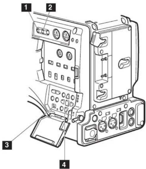
1 HOLD button
2 COUNTER button
3 TCG switch
4 CURSOR and SET buttons
1 Set the COUNTER button to UB.
2 Position the TCG switch at [SET].
- When the left digit starts blinking you can change the value.
3
Use CURSOR buttons to set the user bits.
UB PRESET
▶ button: Shifts the target (highlighted) digit to the right.
◀ button: Shifts the target (highlighted) digit to the left.
▲button: Increases the highlighted number by one.
▼button: Decreases the highlighted number by one.
(SET) button: Confirms the set user bits.
- Pressing the RESET button while setting the user bits will reset any user bit setting to 0.
4
Press the SET button to confirm the user bit value, and position the TCG switch at F-RUN or R-RUN.
Changing the TCG switch setting without pressing the SET button disables the set value.
5
Open the setting menu RECORDING SETUP screen and set the menu option UB MODE to USER.
Retaining the user bits
The data set for the user bits are automatically saved and retained even if the video camera-recorder is turned off.
Frame rate information recorded in user bits
Video is captured at the frame rate set in the setting menu REC FORMAT (setting menu FRAME RATE in FILM CAM 720P) and the recorded video information is recorded in the user bits to allow use in an editing device (PC editing software). In CAMERA mode recording, this information is always recorded in the VIDEO AUX area user bits. Setting the setting menu UB MODE to FRM. RATE, records the information also to the user bits in the subcode area. In playback of clips recorded at 720P native, the same frame rate information as that obtained in playing back the user bits in the VIDEO AUX area is also output to the user bits in the subcode area.
■Frame rate information
Frame rate, video pull-down and time code user bits are related as described below.

When 1080i, 480i or 576i
Frame rate: 24P over 60i (2:3)
☐First field of updated frame rate
Time code digit

Video

Sequence No.

Updated frame information

Frame rate: 24PA over 60i (2:3:3:2)
Time code digit

Video

Sequence No.

Updated frame information

Frame rate: 30P over 60i (2:2)
25P over 50i (2:2)
Time code digit

Video

Updated frame information

720P mode
Frame rate: 24P over 60P (2:3)
□Updated frame
Time code digit
| 02 | 2500 | 01 | 03 | 04 | 05 | 083 | 24 | 26 | 27 | 28 | 29 |
Video
Updated frame information
| 01 | 1010 | 10 | 01 | 00 | 10 | 1001 | 00 | 10 | 1 | 01 | 0 |
Frame rate: 30PA over 60P (2:2)
25PA over 50P (2:2)
Time code digit
| 0200...01 |
Video
| A | A | B | B | C...C |
Updated frame information
| 1010...10 |
Setting the Time Code
1 Switch the menu option TC MODE on the RECORDING SETUP screen to DF or NDF using the menus. (In 59.94 Hz mode)
For details on menu operation, refer to [Using the menus] (page 116).
- Select DF to advance time code in drop frame mode and NDF in non-drop frame mode. Note that 24P, 24PA and 24PN are always recorded in NDF mode.
2 Use the COUNTER button to switch to time code display
3 Position the TCG switch at [SET].
4 Use the CURSOR buttons to set the time code.
- The time code setting range extends from 00:00:00:00 to 23:59:59:29.
TC PRESET
REC RUN
00 h 00 m 00 s 00
+/- : PUSH ▶/ ■
SEL : PUSH ◀◀ /▶▶
PRESET : PUSH II
▶ button: Shifts the target (highlighted) digit to the right.
◀ button: Shifts the target (highlighted) digit to the left.
▲ button: Increases the highlighted number by one.
▼ button: Decreases the highlighted number by one.
■(SET) button: Use to confirm set time code value.
- Pressing the RESET button will reset any time code setting to 0.
5 Press the SET button to confirm the time code setting, and use the TCG switch to select a time code.
- [F-RUN] steps the time code in free run mode, and [R-RUN] set it in recording run mode.
- When 24P or 24PA is used, the time code is adjusted every 5 frames. Adjust a multiple of four for 24PN, an even number for 30PN and make sure that the seconds plus the frame value makes an even number. The time code cannot be set during recording.
- The set value is not valid if you change the TCG switch position without pressing the SET button.
Time code function during battery replacement
Even during battery replacement the backup mechanism keeps the time code generator functioning.
When the POWER switch has been switched ON OFF ON, the backup accuracy of the time code in free run mode is about ±2 frames.
Time code in 720P native mode
- At 24PN, recording is performed at 24 frames and output uses a 2:3 pull-down scheme to produce 30 frames.
- At a frame rate (capture frame rate) of 24P the speed of recording and the output time code matches actual time, but not at any speed other than 24P. (Example: at 60P recording progresses at 60/24 speed)
- Then the camera operates in Rec Run mode and the time code output at start of recording matches the recording time code.
- This is also the case for other than 30P capture at 30PN and other than 25P capture at 25PN.
24PN recording at 60P capture
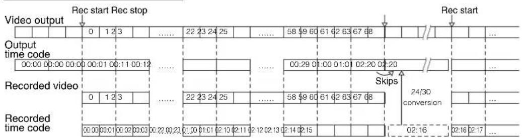
30PN recording at 15P capture

Externally Locking the Time Code
The time code generator built into your AG-HPX500P/E may be locked with an external generator. It is also possible to lock an external time code generator with the internal generator.
Connections for externally locking the time code (examples)
As illustrated, both the reference video signals and the time code must be input.
■Example 1: Locking the time code with external signals

- In addition to an HD Y reference signal, a composite video signal can also be input as reference signal.
■Example 2: Connecting two or more AG-HPX500P/Es with one another, with one being used as the reference device.
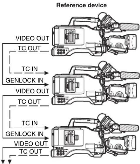
flowchart
graph TD
    A["Reference device"] --> B["VIDEO OUT"]
    A --> C["TC OUT"]
    A --> D["TC IN"]
    A --> E["GENLOCK IN"]
    A --> F["VIDEO OUT"]
    A --> G["TC OUT"]
    A --> H["TC IN"]
    A --> I["GENLOCK IN"]
    A --> J["VIDEO OUT"]
    A --> K["TC OUT"]
Different camera
- On all connected devices, set the setting menu TC VIDEO SYNCRO (OUTPUT SEL screen) to TC IN, GL SELECT (OTHER FUNCTIONS screen) to COMPOSITE and CMPNT/SDI SEL (OUTPUT SEL screen) to AUTO.
- Setting the setting menu TC VIDEO SYNCRO to TC IN will supply the time code via TC IN to the next slave device without delay.
To externally lock the time code
Follow the steps below.
1 Turn on the POWER switch.
2 Position the TCG switch at [F-RUN].
3 Set the COUNTER button to TC.
4 Supply a phase-relationship reference time code (that conforms to the time code requirements) and reference video signals to the TC IN and GENLOCK IN connectors, respectively.
- Now the built-in time code generator is locked with the reference time code.
- When locked to an external time code generator, the time code is at all times locked to the external time code, which is displayed as a highlighted value on the counter indicator. Do not engage the recording mode during the few seconds it takes for the sync generator to stabilize.
-
Once a slave relationship is established, the TC IN and GENLOCK IN connectors stay in slave status. Note that the following events release slave status.
-
When TC PRESET is performed
- When CAMERA mode and MCR mode are switched
• The power is turned off
• The time code mode is switched
• The TCG switch is set to R-RUN
* The slave function locks the time code to the TC IN input and the device will use this time code even if time code input should subsequently cease.
Setting the user bits when the time code is externally locked
To externally lock user bits, set the setting menu TC IN UB REGEN (RECORDING SETUP screen) to ON. Regardless of an F-RUN or R-RUN setting of the TCG switch, the time code is slaved to user bit values input to the TC IN connector.
For details, refer to [Setting Time Data] (page 58) and [Setting user bits] (page 60).
To unlock the externally locked time code
Discontinue external time code supply, then position the TCG switch at [R-RUN].
Cautions in switching the power source from battery to external power supply
Connect the DC IN socket with the external power supply before removing the battery pack, in order to keep the time code generator energized. If the battery pack is removed first, there is no guarantee that the time code will stay externally locked.
External synchronisation of the camera when the time code is externally locked
When the time code is externally locked, the reference video signals input through the GENLOCK IN connector gen-lock the camera.
- To externally lock the AG-HPX500P/E, as the master device, with more than one unit, the mode must be the same as that of the camera. Note that in a system using both interlaced and progressive scanning, there may be breaks in the video and time code.
- Note that switching to MCR mode will disrupt GENLOCK synchronization resulting in loss of image stability.
- When the 24P or 24PA is selected and the time code is externally locked, be sure to input a non-drop frame time code. The time code cannot be externally locked when drop frame mode is selected. When the time code is externally locked, the video may be distorted, but this is because of the 5-frame adjustment and not a malfunction.
Outputting the time code externally
To output time code from the camera's TC OUT connector to a VTR or other recording device in sync with camera picture or playback picture, set the setting menu TC VIDEO SYNCRO (OUTPUT SEL) to VIDEO OUT.
Set also the setting menu GL SELECT (OTHER FUNCTIONS) to SDI or COMPOSITE to suit video output.
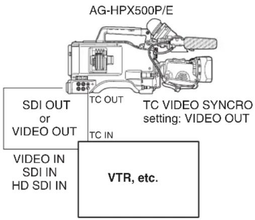
When the setting menu TC VIDEO SYNCRO is set to VIDEO OUT, the time code is output via TC OUT in tune with VIDEO OUT delay.
GENLOCK and time code input/output connection and setup
| Camera operating conditions Camera setup | GENLOCK input and camera output phase (In phase: Out of phase: × ) | |||||||
| Recording format | Video and reference signal to be output externally | GENLOCK input | GL SELECT GL PHASE SDI OUT | VIDEO OUT | TC OUT | Connection diagram | ||
| 1080i | SDI OUT (1080i) | ^1080i POSITE | SDI Disabled | × | (1) | |||
| VIDEO OUT COM | OFF | × | ||||||
| ON | × | ▲90H delay | ▲90H delay | — | ||||
| SDI OUT (1080i) | SD (480i, 576i) | SDI | OFF | × | (1) | |||
| ON | ▲90H advance | × | ▲90H advance | (2) | ||||
| VIDEO OUT COMPOSITE Disabled | × | (1) | ||||||
| 720P | SDI OUT (720P) | SD (480i, 576i) | SDI | OFF | × | (1) | ||
| ON | ▲120H advance | × | ▲120H advance | (2) | ||||
| VIDEO OUT COMPOSITE Disabled | × | (1) | ||||||
| 480i, 576i | SDI OUT (480i, 576i) | SD (480i, 576i) | SDI Disabled | × | (1) | |||
| VIDEO OUT COMPOSITE Disabled | × | |||||||
■Connection diagram (1)

flowchart
graph TD
    A["AG-HPX500P/E"] -->|TC IN| B["GENLOCK"]
    B -->|TDI or VIDEO OUT| C["VTR, etc."]
    C -->|REF| D["HD signal or SD signal"]
    D --> A
Counter Setting and Display
Pressing the COUNTER button to view the counter displays the counter value on the time code indicator in the LCD and in the viewfinder. The counter value is indicated in "Hour : Minute : Second" format.
The counter can display the total recording time but is not displayed during playback.
The recording CTL counter value is retained also when P2 cards are replaced and after a power down. At next power up, the counter starts from the value reached at the previous power down.
- Pressing the RESET button when the counter value is displayed resets the counter to 0.
- The counter value indicates values in the range between 0:00:00 and 9:59:59 at 1-second step.
■Connection diagram (2)

flowchart
graph TD
    A["TC"] --> B["SD signal"]
    B --> C["GENLOCK"]
    C --> D["SDI"]
    D --> E["Down-conversion (Delay)"]
    E --> F["COMPOSITE"]
    F --> G["SD device"]
    G --> H["REF"]
    H --> I["TC"]
    I --> J["SD signal"]
    style A fill:#f9f,stroke:#333
    style J fill:#f9f,stroke:#333
Viewfinder Screen Status Displays
In addition to video images, the viewfinder displays lamps and text that indicate the settings and operating status of the AG-HPX500P/E, together with messages, a center marker, a safety zone marker and the camera ID.
Lamps in the Viewfinder Screen

flowchart
graph TD
    A["1"] --> B["TALLY / REC"]
    C["5"] --> D["50"]
    E["2"] --> F["BATT"]
    G["○"] --> H["SAVE"]
The illustration above shows the supplied viewfinder and the optional AG-VF11G viewfinder, which is equivalent to the supplied one.
When using a viewfinder other than these two viewfinders, see the Operating Instructions provided with that viewfinder.
1 TALLY/REC (recording) Lamp
This lamp stays illuminated during recording, and starts blinking if any abnormal action occurs. For more information, see [Warning System] (page 142).
2 Abnormal Operating Status Warning Lamp
This lamp comes on when this unit is in any of the abnormal operating statuses specified through the menu options in the VF ! LED screen.
For statuses that activate the lamp, see the option in the section [VF! LED screen] (page 126).
3 BATT (battery) Lamp
This lamp starts blinking a few minutes before the battery charge starts to run out, and stays illuminated after the battery is completely flat. The battery should be replaced before it is nearly flat, so that operation will not be interrupted. For more information, see [Warning System] (page 142).
4 SAVE Lamp
This lamp lights when the SAVE switch is set to ON and the LCD is off.
5 50M indication lamp
Not used on this camera.
Viewfinder Status Indication Layout
The indications are arranged as illustrated below.

For more information, see the following pages:
Selecting Viewfinder Display Information
To select items in the viewfinder screen, open the DISPLAY SETUP screen and turn on or off each item or type.
Refer to the section [Using the menus] (page 116).
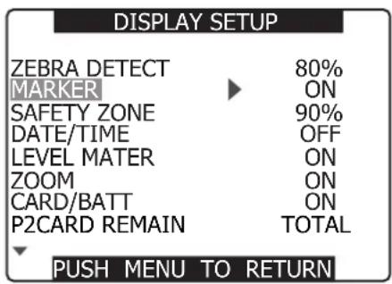
Screen displays

1 Time code displays
Each time you press the COUNTER button, the display switches over to the following data (or no indication).
- No indication
- Counter: Counter value (only in recording mode)
• TC: Time code value
"TC*" is displayed when the time code value cannot be correctly read from 1394 connector input.
The colon ( : ) between the seconds and the frames changes to a period ( . ) in drop frame mode.
• tc: Time code value (frame digits are indicated in 24/30 frame conversion: 59.94 Hz FILM CAM only)
"tc*" is indicated when the time code value cannot be correctly read from 1394 connector input.
The colon ( : ) between the seconds and the frames changes to a period ( . ) in drop frame mode.
- UB: User bit value
"UB*" is indicated when the user bit value cannot be correctly read from 1394 connector input.
• FR: Frame rate information for recording
• FR 60I: 60i interlace mode (60 fields/sec.)
- FR 60P: 60P progressive mode (60 frames/sec.)
- FR 30P: 30P progressive mode (30 frames/sec.)
• FR 24P: 24P progressive mode (24 frames/sec.)
- FR24PA: 24P advanced mode (24 frames/sec.)
• FR50I: 50i interlace mode (50 fields/sec.)
- FR50P: 50P progressive mode (50 frames/sec.)
- FR25P: 25P progressive mode (25 frames/sec.)
In FR24P and FR24PA modes, the last digit indicates the frame conversion sequence information.
When TC, tc and UB are locked to the TC IN input, white characters over a background (TC → TC) appear.
When the HOLD button is used to temporarily stop the indication, the HOLD indication blinks.
2 Warnings
- P2: Flashes when no P2 card is inserted or the card is write protected.
• P2 FULL: Blinks when there is no remaining capacity in the P2 card. - P2 LACK: Blinks in the loop rec mode when the remaining capacity of the P2 card is insufficient.
- Lights when the battery for the internal clock is depleted.
3 Backup unit displays
- The status of the backup unit connected to the 1394 connector is displayed here.
- Nothing is displayed if in the setup menus, OTHER FUNCTIONS screen, 1394 CONTROL, you have selected "OFF".
●1394 ● Recording
●1394 ■Recording standby
● 1394 The backup unit cannot be controlled.
●1394: The backup unit is not connected.
●1394— —: The backup unit is connected but is in a mode other than recording or recording standby.
4 Recording format and system frequency indication
- Recording format
- HD1080i: Records in the 1080i DVCPRO HD format
- HD720P: Records in the 720P DVCPRO HD format
- 50M: Records in the 480i and 576i DVCPRO 50 format
• 25M: Records in the 480i and 576i DVCPRO format
• DV: Records in the 480i and 576i DV format
- System frequency
- 60: 59.94 Hz
- 50: 50 Hz
5 Information display
Following information is displayed depending on the situation.
• Performance of the auto white balance or the auto black balance
- Warning and error indication
- When the DISP/MODE CHK button is depressed, the functions assigned to the USER buttons and !LED settings appear.
6 Squeeze information
Appears when in the setup menus, CAMERA SETUP screen, ASPECT CONV, you have selected "SQUEEZE" or when playing back images recorded in the squeeze mode.
7 AWB display
- LOWLIGHT: Appears when the brightness level adjusted by the auto white balance is too low.
- C TEMP **: Adjusting the auto white balance, turning the WHITE BAL switch or turning on the power displays the color temperature when COLOR TEMP in the setting menu SCENE FILE screen is set to something other than 0.
8 Marker luminance display
When markers are displayed, the brightness level around the center of the screen is indicated as 0% to 99%. “99% ↑” appears if the percentage is over 99.
9 Calendar
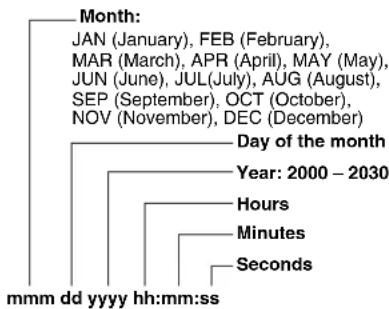
10 Recording/playback frame rate display
Apart from 720/30PN, 720/24PN, and 720/25PN, only the recording frame rate is displayed.
Example: 60:24P (VFR recording and playback at 24P to 60P capture)
Playback applies a 2:3 pull-down to perform 24P over 60, indicating that a 24/60 speed slow playback is performed.
11 Shutter speed
The shutter speed is displayed here.
The synchro scan function sets time (minutes) display in VIDEO CAM mode and shutter opening angle (degrees) in FILM CAM mode.
12 Audio level meter display
At a HEAD ROOM of -20 dB

At a HEAD ROOM of -18 dB

13 IRIS display
Displays F value.
- "NC" appears when the lens connector is not connected.
14 Zoom position display
The zoom poison is displayed with Z00 (maximum wide-angle) - Z99 (maximum zoom).
15 Auto iris control displays
- SPOT: Auto iris control for spotlight
- BACK: Auto iris control for backlight compensation
Also appears when the lens is set to manual iris, but does not function.
16 Remaining battery charge
As the remaining battery charge drops, the display changes as follows: 🐎 → 🐎 → 🐎 → 🐎 When the battery has completely discharged, 🐎 (○) blinks.
(When the AC adapter is being used, a display other than 📄 may appear: this is not a sign of malfunctioning.)
- 13.5V: Battery voltage indication Indicates the current voltage for analog batteries.
- XX%: 10% to 99% Indicates the remaining battery level in % for digital batteries. This value is not indicated on the meter.
- MAX: Indicates that a digital battery is fully charged.
- EMP: Indicates that a digital battery has a remaining charge of less than 10%.
- Battery type indication Holding down the DISP/MODE CHK button will show the value currently set for battery remaining level indication.
“AC ADPT” is shown when the AC adapter is used.
17 Text memo and shot mark indicator
- This indicator lights when text memos are inserted during recording or playback by pressing the USER button to which the TEXT MEMO function has been assigned.
- “MARK ON” appears when shot marks are inserted during recording by pressing the USER button to which the SHOT MARK function has been assigned.
A second press will delete the shot mark and MARK OFF appears.
- "INVALID" appears when a text memo could not be entered or a shot mark could not be recorded or deleted.
18 Recommended ND filter
The recommended ND filter under the current shooting conditions is displayed here.
19 ND filter display
- ND filter selected is displayed.
- An "ND –" indication means that the ND FILTER switch is incorrectly set (a position other than ND1 to ND4). Check ND FILTER switch position.
20 Gain display
Displays the gain value of the image amplifier configured.
21 WHITE BAL switch position indication
Indicates the switch position currently selected. Also indicates white balance operation when AWB is set to "preset".
22 Center marker display
Markers are displayed when the MARKER item in the setting menu DISPLAY SETUP screen is set to ON.
23 Scene file name display
Indicates name of SCENE FILE (F1 to F6).
24 Media remaining memory display
- Setting the setting menu P2 CARD REMAIN (DISPLAY SETUP) to ONE-CARD displays the remaining time on the P2 card that is currently being recorded and the number of the slot it resides in. Setting P2 CARD REMAIN to TOTAL displays the remaining time on all four cards.
- In a mode check, "ONE-CARD" and "TOTAL" are alternately displayed.
- There is no display while the remaining memory is being calculated. "LOOP" is displayed during Loop recording (LOOP REC).
- In a mode check during loop recording, the minimum guaranteed available recording time is displayed.
- Indicates remaining time in 1-minute increments from 0 to 999 minutes.
- The display blinks when 2 minutes or less time is left.
25 Operational state display
- REC: Recording
• PAUSE: Recording pause - Play pause
•▶(✗ Play (reverse play) - ▶(): Fast-forward/Fast-forward play (Rewind/Fast-backward play)
• Slow play (Reverse slow play) - CHK: Rec check
- I): I frame-by-frame (Reverse Frame-by-frame)
• × ▶/ × ▶(× / ◀ ):◀Variable-speed search (Reverse variable-speed search) - CLIP ▪CLIP ▪Clip forward (Clip reverse) Cue up of single clips
Not displayed when the LCD is off in CAMERA mode. (But displayed when pre-recording, interval recording or one-shot recording is set.)
26 Media information display
The card slot where the P2 card was inserted and the basic information of the media are displayed here.
• 1 lights: P2 card on which data can be recorded.
• 1 lights green: P2 card on which data is to be recorded.
- 1 Flashes: Card recognition underway, or a card other than that on which data is to be recorded in special recording mode
- —: No card inserted.
• P : Write-protected
• F : Full memory
• X : Cannot recognize
- E: a P2 card in an invalid format (Returns to normal if formatted.)
27 Special recording display
This display appears when the REC FUNCTION option of the setting menu RECORDING SETUP screen is set to INTERVAL, ONE SHOT or LOOP, and when PRE REC is set to ON. A P2 card inserted in a free slot after start of a special recording mode is not used for recording. Insert P2 cards before start of recording. Stop special recording and insert the P2 card again.
28 Lens chromatic aberration compensation (CAC) indicator
During a mode check, it indicates that lens chromatic aberration compensation (CAC) operates normally.
29 AWB, ABB error indication
In a mode check, the status of AWB and ABB that do not operate normally is shown.
■Safety zone
The range of the zone is indicated by the SAFETY ZONE item on the DISPLAY SETUP screen.
• 4:3:
This indicates the position which is cropped to 4:3.
• 90%:

This indicates the range (90%) in which signals can be displayed by an ordinary home-use TV set.
Warnings
• COPY INHIBITED
Input of DV formats via the 1394 connector in MCR mode cannot be recorded normally since the contents are copyright protected.
• EXTERNAL 1394 DISCONNECT
When the 1394 CONTROL item of the OTHER FUNCTIONS screen of the setup menu is set to EXT and recording without connecting external units with 1394 terminal, this display appears.
• INCOMPATIBLE CARD
The card cannot be used since it does not comply with the specified standard.
• DIR ENTRY NG CARD
Indicates a card where folder location has become corrupted. This type of card cannot be used for special recording modes (interval, ONE SHOT and loop recording).
A warning appears when such a P2 card is inserted in a P2 device or when recording is completed.
• RUN DOWN CARD
Indicates that a P2 card has nearly reached the end of its life. This warning message appears each time the card is inserted or recording is stopped, and it will continue to appear until the card is replaced with a P2 card with sufficient life remaining. Proper recording and playback may not be possible with a P2 card that is near the end of its life, so we recommend replacing it with another one as soon as possible.
- FORMAT ERR!
Indicates a P2 card that does not meet the P2 card standard.
• CANNOT ACCESS
Cannot access clips.
• CANNOT DELETE
Cannot delete clips.
• CANNOT FORMAT
Cannot format P2 cards or SD memory cards.
• CANNOT REPAIR
Cannot repair clips.
- CARD FULL
The P2 card does not have enough free space for recording.
• WRITE PROTECTED
The P2 card or SD memory card is writeprotected.
- NO CARD
A P2 card or SD memory card has not been inserted.
• NO FILE
There are no files (version upgrade files, etc.).
P2 card playback data indication
- EOS: End of stream. No more data is available in the forward playback direction.
- BOS: Beginning of stream. No more data is available in the rearward playback direction.
- P2 SLOT: Appears when pressing the USER button to which SLOT SEL is assigned.
Errors
These are displayed when an error occurs in the unit, P2 card, tape, or other component. If the problem is not fixed by turning the power off and then on again, either replace the card or tape based on the error information, or consult with your dealer as to which one is to be purchased.
• CANNOT REC
This is displayed during a recording error.
• CANNOT PLAY
This is displayed when trouble has occurred during playback.
• CARD ERR (1) (2) (3) (4) (1/2/3/4):
Trouble has occurred in the P2 card found in the slot indicated by the number.
- CLIP ERROR: clip trouble
• UPDATING: Reading card data
• ERROR: other type of trouble
- SYSTEM ERROR
This is displayed when trouble has occurred in the system. Switch ON the power again.
- P2 MICON ERROR: No P2 microcomputer response
- P2 CONTROL ERROR: Trouble in P2 control
• REC RAM OVERFLOW: Recording RAM overflow
• TURN POWER OFF
This message indicates that an abnormal event has occurred, for example, that a card has been removed during access or that a change in system frequency has been made. Turn the power off and then turn it back on again.
- REC WARNING
This is displayed when trouble has occurred during recording. Carry out recording once again. If the warning persists, consult your dealer.
• CARD ERR (1) (2) (3) (4) (1/2/3/4):
Trouble has occurred in the P2 card found in the slot indicated by the number.
- If the warning continues, turn off the power.
- If the warning appears even when recording is carried out again, replace the card with another one.
• ERROR: Other type of trouble
• 1394
This is displayed when trouble has occurred in the 1394 connections or signals.
• 1394 INITIAL ERROR: Connection error
• 1394 INPUT ERROR: Input error
- 1394 INPUT ERROR (OTHER FORMAT): (Wrong input format)
- LOW BATTERY:
Indicates that the battery is exhausted.
Camera status display
- AWB: AWB indicator
• ABB: ABB indicator - AWB P3.2 K/AWB P5.6K: Displays the color temperature assigned to PRST when the WHITE BAL switch is set to PRST. Also displayed when AWB is performed in the PRST position.
- GAIN **dB: Displayed when GAIN is switched.
- BACK LIGHT (OFF): Displayed during iris control when back light status is changed by pressing the user button to which BACK LIGHT is assigned.
- SPOT LIGHT (OFF): Displayed during iris control when back light status is changed by pressing the user button to which SPOT LIGHT is assigned.
- SHUTTER 1/**** (OFF): Displayed when the shutter speed is changed.
- SCENE *****: Displays the name of a scene file selected by turning the SCENE FILE dial.
- ND NG: Displayed when the ND filter is not working normally.
- AUTO KNEE (ON/OFF): Displayed when changing the AUTO KNEE switch position.
USER buttons assignment information (at mode check)
Displays the function assigned to each USER button. For details, see [Assigning Functions to USER buttons] (page 55).
! LED light indication (at mode check)
Indicates why an ! LED is lit according to setting menu VF! LED screen settings.
- GAIN: Indicates the camera is using a gain value other than 0 dB.
- AWB: Indicates that the WHITE BAL switch is set to PRST.
- SHUT: Indicates the electronic shutter is operating.
- FILT: Appears when the filter set by menu is met.
- EXT: Indicates when the lens extender is inserted.
Checking and displaying shooting status
- Hold down the DISP/MODE CHK button in recording standby or during recording to display the settings of each shooting function, the list of functions assigned to USER buttons and all other information. Press again to return to the regular screen.
- Press the DISP/MODE CHK button during recording standby or recording clears all displays. Press again to return to the regular display.
• These settings are maintained when the unit is turned off and also when switching media and operating mode. - Display the following items on the viewfinder and LCD monitor screen by pressing the DISP/MODE CHK button or by configuring OTHER DISPLAY of the DISPLAY SETUP screen of the setup menus.
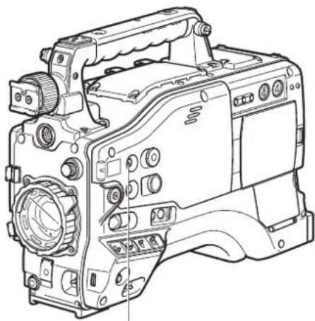
natural_image
Line drawing of a digital camera with no visible text or symbolsDISP/MODE CHK button
| Displays | MODE CHECK | DISPLAY | Audio dubbing mode | |||
| ALL | PARTIAL | OFF | ||||
| 1 | Time code display | ○ | — — | — — | ||
| 3 | Backup unit display — × | ○ | ○ ○ | |||
| 4 | Recording format and system frequency indication | ○ | ○ ○ | × | × | |
| 5 | Information display | ○ | — — | — — | ||
| 6 | Squeeze information | ○ | ○ ○ | ○ | × | |
| 8 | Marker luminance display | ○ | ○ | — — | — | |
| 9 | Calendar | ○ | ○ | — — | — | |
| 10 | Recording/playback frame rate display | ○ | ○ ○* | 1 | × | × |
| 11 | Shutter speed | ○ | ○ ○ | ○ | × | |
| 12 | Audio level meter display | ○ | ○ | — — | — | |
| 13 | RIS display | ○ | ○ ○ | ○ | × | |
| 14 | Zoom position display | ○ | ○ | — — | — | |
| 15 | Auto-iris control display | ○ | ○ ○ | ○ | × | |
| 16 | Remaining battery charge | ○ | ○* 4 | — — | — | |
| 18 | Recommended ND filter | ○ | ○ ○ | ○ | × | |
| 19 | ND filter display | ○ | ○ ○ | × | × | |
| 20 | Gain display | ○ | ○ ○ | ○* | 2 | × |
| 21 | WHITE BAL switch position indication | ○ | ○ ○ | ○* | 3 | × |
| 22 | Center marker display | ○ | × — | — — | ||
| 23 | Scene file name display | ○ | ○ ○ | × | × | |
| 24 | Media remaining memory display | ○ | ○* 4 | — — | — | |
| 25 | Operating status display | ○ | ○ | — — | — | |
| 26 | Media information display | ○ | ○ | — — | — | |
| 27 | Special recording display | ○ | ○ | — — | — | |
| 28 | Lens chromatic aberration compensation (CAC) indicator | ○ | — × × × | |||
| 29 | AWB, ABB error indication | ○ | × × × × | |||
| Safety zone display | — × | — — | — | |||
O: Displayed
x: Not displayed
—: Displayed depending on other settings
The item in ○ in the MODE CHECK space appears when you press and hold the DISP/MODE CHK button.
The item in O in the DISPLAY space disappears when you press the DISP/MODE CHK button.
*1 Not displayed when FRAME RATE is set to 60i or 50i.
^*2 0 dB is not displayed.
*5 Only preset 3.2K and 5.6K are displayed.
*4 Blinks when there is little remaining time left.
Setting the Marker Displays
Turn marker display on or off.
Select the display mode from the setting menu DISPLAY SETUP screen.
For directions on navigating the menu, see [Using the menus] (page 116).
DISPLAY SETUP
| ZEBRA DETECT | 80% |
| MARKER | ON |
| SAFETY ZONE | 90% |
| DATE/TIME | OFF |
| LEVEL MATER | ON |
| ZOOM | ON |
| CARD/BATT | ON |
| P2CARD REMAIN | TOTAL |
| PUSH MENU TO RETURN | |
You can also press the USER button to which the MARKER function has been assigned to turn the marker on and off.
Adjusting and setting the LCD monitor
Using the LCD Monitor
1 Turn on the POWER switch of the AG-HPX500P/E.
2 Slide the OPEN button in the arrow ① direction to open the LCD monitor.

natural_image
Line drawing of a video camera with labeled parts (no text or symbols present)
The LCD monitor opens to an angle of 120 degrees. Attempts to open it further will damage the monitor.
3 Adjust the angle of the LCD monitor for most convenient viewing.
- The monitor can turn up to 180 degrees towards the lens and up to 90 degrees towards you.
To prevent camera-recorder failure, do not allow undue force to be applied to the monitor (when it is open).
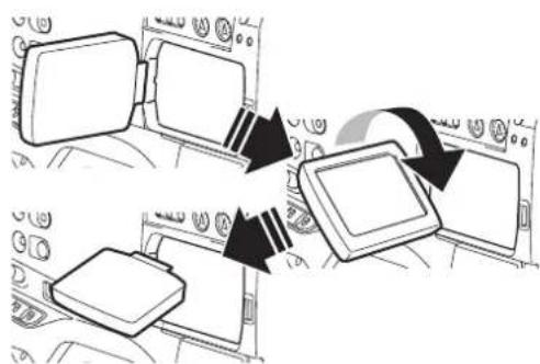
flowchart
graph TD
    A["Start"] --> B["Add"]
    B --> C["Add"]
    C --> D["Add"]
4 Use the menu option LCD SET (DISPLAY SETUP) to adjust the brightness, color level and contrast of the screen.
For details on menu operation, refer to [Using the menus] (page 116).
- At LCD SET of the DISPLAY SETUP screen, select YES.

5 Use the JOG dial button to select an item.
![LCD SET LCD COLOR LEVEL [−] [+] LCD BRIGHTNESS [−] [+] LCD CONTRAST [−] [+] PUSH MENU TO RETURN](/content/2026/06/1254106/images/316666f9f2662eacf8919febd0d11f1d5230693682bc5f43f6de68f21b5ccb07.jpg)
6 Press the JOG dial button, and turn the JOG dial button to adjust the selected item.
![LCD SET LCD COLOR LEVEL [-] [+] LCD BRIGHTNESS [−] [+] LCD CONTRAST [−] [+] PUSH MENU TO RETURN](/content/2026/06/1254106/images/5cbce55e4c178c42bbd1ffc4eba82f3b6b720089940e0c69daa54194c07bf7f9.jpg)
- Pressing the RESET button when a value that can be adjusted is selected in the setting menu LCD SET will return the setting to its factory default.
- When closing the LCD monitor make sure that it is shut tight.
- In an environment with sudden temperature changes, condensation may form on the liquid crystal surface of the monitor. If this happens, wipe off the moisture with a soft, dry cloth.
- When the camera-recorder is very cold, the video image in the LCD monitor will appear slightly darker immediately after the power is turned on. Once the interior of the camera-recorder warms up, the LCD monitor delivers normal brightness.
- When the SAVE switch is set to ON, the LCD monitor is forcibly disabled.
Self-portrait Shooting
When shooting with the LCD display angled 180 degrees towards the lens, you can set the menu option SELF SHOOT to MIRROR, to horizontally flip the video image on the LCD display, and allow you to view a mirror image while shooting.
Note that only the video image on the LCD monitor is horizontally flipped, not the actual video being recorded.
The menu option SELF SHOOT can be found in the DISPLAY SETUP screen.
Handling setup data
Configuration of setup data files
This camera makes it possible to save a scene file to each of the F1 to F6 positions on the SCENE FILE dial. Use of an SD memory card makes it possible to save up to four of the F1 to F6 files on an SD card for later retrieval.
The setting menu values can be stored as a user file in the camera and up to four files can be stored on the SD memory card.
The setting data files are configured as shown below.
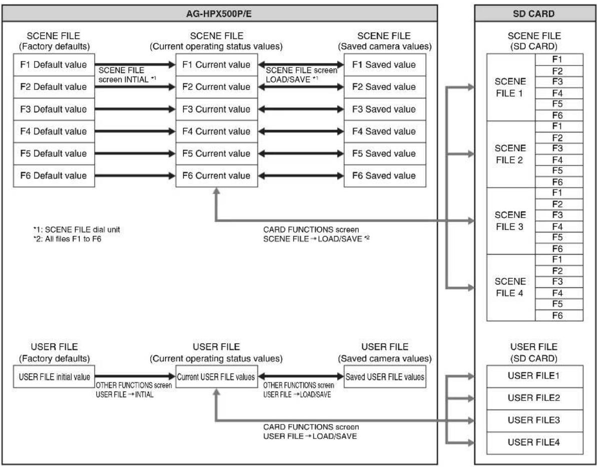
flowchart
graph TD
    subgraph AG-HPX500P/E
        A1["SCENE FILE (Factory defaults)"]
        A2["F1 Default value"] -->|SCENE FILE screen INITIAL *1| B1["F1 Current value"]
        A3["F2 Default value"] --> B2["F2 Current value"]
        A4["F3 Default value"] --> B3["F3 Current value"]
        A5["F4 Default value"] --> B4["F4 Current value"]
        A6["F5 Default value"] --> B5["F5 Current value"]
        A7["F6 Default value"] --> B6["F6 Current value"]
    end

    subgraph SD_CARD
        C1["SCENE FILE (SD CARD)"]
        C2["SCENE FILE 1"] --> D1["F1"]
        C2 --> D2["F2"]
        C2 --> D3["F3"]
        C2 --> D4["F4"]
        C2 --> D5["F5"]
        C2 --> D6["F6"]
        C3["SCENE FILE 2"] --> E1["F1"]
        C3 --> E2["F2"]
        C3 --> E3["F3"]
        C3 --> E4["F4"]
        C3 --> E5["F5"]
        C3 --> E6["F6"]
        C4["SCENE FILE 3"] --> F1["F1"]
        C4 --> F2["F2"]
        C4 --> F3["F3"]
        C4 --> F4["F4"]
        C4 --> F5["F5"]
        C4 --> F6["F6"]
        C5["SCENE FILE 4"] --> G1["F1"]
        C5 --> G2["F2"]
        C5 --> G3["F3"]
        C5 --> G4["F4"]
        C5 --> G5["F5"]
        C5 --> G6["F6"]
        C6["USER FILE (SD CARD)"]
        C7["USER FILE 1"] --> U1["USER FILE (SD CARD)"]
        C8["USER FILE 2"] --> U2["USER FILE (SD CARD)"]
        C9["USER FILE 3"] --> U3["USER FILE (SD CARD)"]
        C10["USER FILE 4"] --> U4["User FILE (SD CARD)"]

    B1 <--> B2 <--> B3 <--> B4 <--> B5 <--> B6

    B1 <--> B2 <--> B3 <--> B4 <--> B5 <--> B6

    B1 <--> B3 <--> B4 <--> B5 <--> B6

    B1 <--> B4 <--> B5 <--> B6

    B1 <--> B6

    style AG-HPX500P/E fill:#f9f,stroke:#333
    style SD_CARD fill:#ccf,stroke:#333
Setting Data Using an SD memory card
An SD or SDHC memory card (optional accessory) can be used as a setup card that stores up to four files of settings menu specifications. This data allows you to quickly reproduce an optimum state. See [Memory Card Usage] (page 83).
Handling SD memory cards
An SD memory card may be inserted or removed, either before or after the power is turned on.
To insert an SD memory card
Open the lid of the switch cover, and insert an SD memory card (optional accessory) into the SD memory card slot with the notch upward. Close the lid.

natural_image
Technical line drawing of a mechanical device with internal components and an inset showing a close-up of its internal structure (no text or symbols present)An SD memory card must be inserted with the right side facing the slot. If the card is hard to insert, it may be reversed or upside down. Do not force it into the slot. Check the card before reinserting it.
To remove the SD memory card
Open the lid of the switch cover, and ensure that the BUSY lamp is not illuminated. Then, further depress the SD memory card towards the main unit. This releases the SD memory card from the insertion slot. Take hold of the SD memory card and remove it. Close the lid.
SD memory cards must not be used or stored in an environment where they may be
- Exposed to high temperatures/humidities;
- Exposed to water droplets; or
• Electrically charged.
For storage, the SD memory card must be kept inserted into the AG-HPX500P/E with the lid closed.
Formatting, Writing and Reading an SD memory card
Open the CARD FUNCTIONS screen from the setting menu to format SD memory cards, write setting data to SD memory cards and to read data stored on an SD memory card.
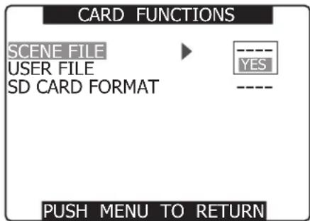
For an SD memory card formatted with a device that does not support SD/SDHC standards, the message "FORMAT ERROR" appears at the upper right of the screen. In this case, reformat the card as follows. See [To format an SD memory card] (page 78).
To format an SD memory card
SD memory cards may be formatted via the thumbnail screen. For more information, see [Formatting SD memory cards] (page 112).
1 Navigate the menu to the
For details on menu operation, refer to [Using the menus] (page 116).
2 Turn the JOG dial button to move the cursor to the menu option SD CARD FORMAT.
3 Press the JOG dial button.
4 To format the SD memory card, turn the JOG dial button to move the cursor to YES. Then, press the dial button.
- "SD CARD FORMAT OK" appears and the SD memory card is formatted.

The card will not be formatted if the following message appears when the JOG dial button is pressed:
| Error message Remedy | |
| SD CARD FORMAT NG NO CARD(No SD memory card inserted.) | Insert an SD memory card. |
| SD CARD FORMAT NG ERROR(SD memory card cannot be formatted.) | The card may be defective.Replace the card. |
| SD CARD FORMAT NG WRITE PROTECT(SD memory card is write-protected.) | Remove the card and cancel the protect. |
| SD CARD FORMAT NG CANNOT ACCESS(SD memory card not accessible). | The SD memory card is not accessible. When the current access operation ends, reformat the card. |
How to Use Scene File Data
- The settings according to the variety of shooting circumstances are stored in each position of scene file dial.
- When shooting, you can retrieve the necessary file instantly using scene file dial.
- You can also use menu options to change set scene file values. A modified scene file can be saved to each scene file dial position.

- During recording, the OPERATION TYPE and FRAME RATE settings remain unchanged even when the scene file is changed. To change these settings, set the camera-recorder to recording standby state.
■Factory setting
• F1: SCENE
File suitable for normal shooting.
• F2: SCENE FLUO.
File suitable for shooting under fluorescent lights, ie. indoors.
• F3: SCENE SPARK
File suitable for SD shooting with fuller variations of resolution, coloring and contrast.
• F4: SCENE B-STR
File for broadening the contrast of dark parts, such as when shooting sunsets.
• F5: SCENE CINE V
File suitable for shooting movie-like scenes where the contrast is to be emphasized. (The recording format remains unchanged even when the scene file is changed. It must be set using the REC FORMAT option on the RECORDING SETUP screen.)
• F6: SCENE CINE D
File suitable for shooting movie-like scenes where the dynamic range is to be emphasized.
(The recording format remains unchanged even when the scene file is changed. It must be set using the REC FORMAT option on the RECORDING SETUP screen.)
Changing scene file settings
■Example1: Change the name of the scene file.
1 Turn the scene file dial, then select the scene file to be changed.
2 In the setup menus, open the SCENE FILE screen.
3 Turn the JOG dial button to move the cursor to the option NAME EDIT. Then, press the JOG dial button.
For details on menu operation, refer to [Using the menus] (page 116).

4 Turn the JOG dial button to move the cursor to YES. Then, press the JOG dial button.
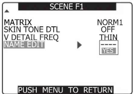
5 When the screen shown below appears, use the JOG dial button to enter a 6-character file name.
- Turning the JOG dial button changes the character display in the following order: space (☐) → alphabet (A to Z) → numerics (0 to 9) → symbols (; : <= > ? @ [ \ ] ^_-./).
- If the RESET button is pressed when the filename has been set, the characters are cleared.

6 After you finish setting the filename, press the MENU button.
- This completes the NAME EDIT change. A change that has been confirmed is retained after a power down and is not affected by dial position. Items set for the scene file are also retained.
■Example2: Save the F1 scene file to the camera.
1 Turn the JOG dial button to move the cursor to the option LOAD/SAVE/INT. Then, press the JOG dial button.
For details on menu operation, refer to [Using the menus] (page 116).

2 Turn the JOG dial button to move the cursor to the option SAVE. Then, press the JOG dial button.

3 Turn the JOG dial button to move the cursor to YES. Then, press the dial button.
- To return to the menu level above, press the MENU button.

- "PROCESSING" appears and the following message is shown when all settings have been completed.
- After changing the scene file settings, to return to the settings to the previously saved values, select LOAD in step 2 and perform the operation described in step 3.
- To return the scene file settings to their factory defaults, select INITIAL in step 2 and perform the operation described in step 3.
- To save and read user file settings or return them to their factory defaults, open the setting menu OTHER FUNCTIONS screen and run USER FILE in the same way as when handling scene files.
Saving scene files and other settings on SD memory cards
You can save up to four scene file settings or other settings as files on an SD memory card, and you can also load them from the card.
- In the case of the scene files, the current settings are automatically saved in the unit, and the saved data is written on an SD memory card. When data has been read from an SD memory card, the current settings are rewritten at the same time as the data saved inside the unit.
- The data in all the scene files, F1 to F6, is rewritten.
The following procedure shows how to save scene files.
1 Set the unit's POWER switch to ON.
2 Select SCENE FILE on the setting menu CARD FUNCTIONS screen, select YES, and press the JOG dial button.
For details on menu operation, refer to [Using the menus] (page 116).

3 Select the file number (1 to 4) using the JOG dial button.
- Press the JOG dial button again to confirm the setting.

4 Select WRITE using the JOG dial button, and press the JOG dial button.

5 Press the ←cursor button, turn the JOG dial button to move to YES and again press the JOG dial button.
- In the following example, TITLE 1 is the filename.
- When writing is completed, WRITE OK appears.

To load a file
Perform steps 1 to 3, select READ in step 4, and press the JOG dial button.
When reading is completed, READ OK appears.
Select USER FILE in the CARD FUNCTION screen and process it in the same way as scene files.
Reloading Files From an SD Memory Card
Perform steps 1 and 2, move to TITLE RELOAD so that YES is displayed in step 4, and press the JOG dial button.
The file is reloaded.
To title a file
1 Perform steps 1 to 4.
2 Use the JOG dial button to select characters, then press the JOG dial button to move to the next character.
- You can input any of the following characters: Space, A to Z, 0 to 9, : ; <= > ? @ [ \ ] ^_-./
- You can erase all characters using the RESET button.
3 When all inputs are completed, press the ◀cursor button at the left edge of the characters (or press the ▶cursor button at the right edge or use the JOG dial button).
4 Turn the JOG dial button to select YES and press the JOG dial button.

- "WRITE OK" appears when the title is written.
- If WRITE NG FORMAT ERROR appears, format the SD memory card.
- If WRITE NG WRITE PROTECT appears, release the protected status of the SD memory card.
- If WRITE NG CANNOT ACCESS appears, quit all other operations (such as playback) before proceeding.
- If WRITE NG ERROR appears, the SD memory card may be defective. Replace it.
Memory Card Usage
Use only cards that conform to the SD card standard or the SDHC standard in this camera.
Be sure to use a mini SD card adapter when using mini SD cards. (The camera will not operate normally when only the adapter is inserted, but be sure to insert a memory card in the adapter.)
■Memory cards that can be used
• SD memory cards (including mini SD cards)
- SDHC memory cards
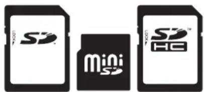
Use of Panasonic SD/SDHC memory cards and mini SD cards is recommended.
The latest information on memory cards that can be used in the camera is provided at our P2 Support Web site. See below.
- The SDHC (SD High Capacity) card is a new standard, established by the SD Card Association in 2006, for large-scale memory cards with capacities above 2 GB.
■Cards that cannot be used
Memory cards other than those mentioned above.
- Multimedia cards

Chapter5 Preparation
Power Supply
A battery pack or an external DC power supply can be used as the power supply for the camera-recorder.
Using a Battery Pack
Battery packs from the following manufacturers can be used:
- Anton/Bauer
• IDX
• PACO - Sony
- Other batteries may be used by changing the menu setting, but system compatibility is not guaranteed.
- Charge the battery pack with the battery charger before using it. (Please refer to the battery charger's instruction manual for information about charging.)
Mounting the Battery and Setting the Battery Type
Using an Anton/Bauer Battery Pack
1 Mount an Anton/Bauer battery pack.
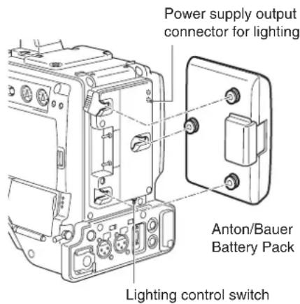
The Anton/Bauer battery holder includes both a power supply output connector for lighting and a lighting control switch, which are convenient when attaching a light. Please contact Anton/Bauer for information about the lighting system.
2 Insert the battery and slide it in the direction of the arrow.

- Removing the battery pack Completely push down and hold the release lever on the battery holder. Then, slide the battery pack in the opposite direction to the arrow while holding the lever down.
3 Set the battery type.
- Select the battery type listed under BATTERY SELECT. Select the menu option BATTERY SELECT from the setting menu BATTERY SETUP screen.
■ The following Anton/Bauer batteries can be used:
- PROPAC14
• TRIMPAC14 - HYTRON50
• HYTRON140
• DIONIC90
• DIONIC160
Using an NP-1 type battery pack
When replacing the battery holder, consult your distributor.
1 Remove the battery holder.

2 Mount the NP-1 type battery case on the camera-recorder.
①Tighten the mounting screws.
②Tighten the power contact screws.
③ Insert the upper part of the removed cover in the direction of the arrow.
④ Align the holes in the bottom part (metal part) of the cover with the holes in the case, and secure the cover with the screw.
When mounting the battery holder, take care not to pinch the connection cord.

When using a V-mount type battery pack
Mount the V-mount adapter plate. Insert the plate and slide it as shown below.

natural_image
Technical line drawing of an electrical switchgear assembly (no text or symbols)Setting the battery type
- Select the battery type listed under BATTERY SELECT. Select the menu option BATTERY SELECT from the setting menu BATTERY SETUP screen.
- When using a battery not listed under BATTERY SELECT:
If it is a NiCD battery, select "NiCd14(14V)" and set each item according to the battery characteristics. If it is not a NiCd battery, select TYPE A or TYPE B and set each item according to the battery characteristics. Please refer to [BATTERY SETUP screen] (page 127) for more information.
For information about the V-mount adapter plate, please contact the store where you purchased the camera-recorder.
Use of the external DC power supply
1 Connect the external DC power supply to the DC IN socket on the unit.
Attach the two ferrite cores (provided) to both ends of the DC cable in such a way that the ferrite cores fit within about 5 cm (2 inches) from the connectors, as shown below. Close each ferrite core until it clicks into place and locks.
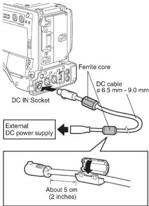
Handle the ferrite cores with care as they are prone to shatter when subjected to an impact force, such as when dropped.
2 Turn "ON" the power switch of the external DC power supply. (If the power switch is available on the external DC power supply)
3 Turn the camera-recorder power switch ON.
- When the power is turned on, a rush current occurs. If the power supply is insufficient during this time, the camera may be damaged. Therefore, we recommend using an external DC power supply that provides at least twice the total power consumed by the camera and all the devices connected to the unit that power on when the camera powers on (example: viewfinder). We also recommend using the proper DC cable recommended for your external DC power supply.
- When using an external power supply other than the AC adapter, check the DC IN socket pin information to ensure correct polarity. If a +12 V power supply is accidentally connected to the GND terminal, this could cause a fire or personal injury.
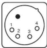
DC IN Socket
| Pin No. Signal | |
| 1 | GND |
| 2, 3 | - |
| 4 | +12V |
- When both the battery pack and the external DC power supply are connected, power is supplied from the external DC power supply. The battery can be removed or mounted while using an external DC power supply.
- When using an external DC power supply, make sure you turn on the external DC power supply before turning on the camera-recorder's power switch. If this sequence is reversed, the camera-recorder may malfunction due to slow rising of the external DC power supply voltage.
- To connect a battery to the DC IN connector, select BATTERY in the EXT DC IN SEL item, and select the battery type in the BATTERY SELECT item in the BATTERY SETUP screen. Note that with these settings, the “%” indication cannot be displayed, even for batteries capable of indicating remaining power.
- Before connecting an external DC power supply, make sure its output voltage is compatible with the rated voltage of the camera.
Mounting the Viewfinder and Adjusting its Position
This section shows how to mount and adjust the supplied viewfinder and the optional AG-VF11G viewfinder, which is equivalent to the supplied one. When using a viewfinder other than these two viewfinders, see the Operating Instructions provided with that viewfinder.
- Note that old attachment models are not supported.
Mounting the Viewfinder
1 Confirm that the POWER switch is turned off.
2 Connect the plug to the viewfinder connector.

3 Loosen the viewfinder right-left positioning ring.
4 Turn the viewfinder securing screw counterclockwise (to cancel the safety mechanism) and slide the viewfinder in the direction of the arrow.

5 Turn the viewfinder securing screw clockwise (to prevent it from falling off).
6 Tighten the viewfinder right-left positioning rings.
Adjusting Viewfinder Right- Left Position
1 Loosen the viewfinder right-left positioning ring.
2 Slide the viewfinder right and left to find a position that facilitates viewing.

3 Tighten the right and left viewfinder positioning ring.
Diopter Adjustments
1 Turn on the POWER switch on the camera.
- Look at the image in the viewfinder.
2 Turn the diopter adjusting ring until you get the sharpest possible image in the viewfinder.
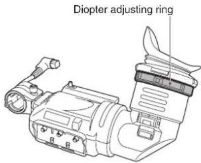
Screen Adjustments
Use the following controls to adjust viewfinder screen.
- Brightness: Turn the BRIGHT control.
- Contrast: Turn the CONTRAST control.
- Peaking: Turn the PEAKING control.
1 Turn on the POWER switch on the camera.
2 Set the OUTPUT switch of the camera to BARS.
3 Turn the viewfinder BRIGHT and CONTRAST controls to adjust viewfinder brightness and contrast.
- Turn the PEAKING control to obtain a sharp image.
- A sharper viewfinder image will facilitate focusing.

Removing the Viewfinder
1 Confirm that the POWER switch is turned off.
2 Loosen the viewfinder right-left positioning rings.
3 Turn the viewfinder securing screw counterclockwise, slide the viewfinder in the direction of the arrow and remove it.

Viewfinder securing screw
4 Disconnect the viewfinder cable and microphone cable from the clamp and remove them.
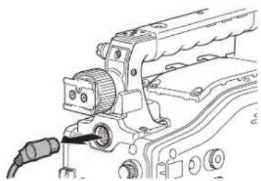
natural_image
Mechanical assembly diagram showing a gear and connector with a cable (no text or symbols)Mounting and Adjusting the Lens
Mounting the Lens
1 Raise the lens clamping lever and remove the mount cap.

2 To mount the lens, align the indentation at the top center of the lens mount with the center mark of the lens.

3 Lower the lens clamping lever to clamp the lens.
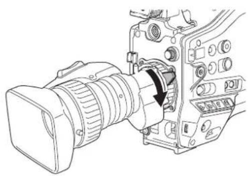
natural_image
Line drawing of a professional video camera with an attached device showing internal components (no text or symbols)4 Secure the cable through the cable clamp, and plug it into the LENS connector.

5 Adjust the lens flange back.
- Please refer to the lens instruction manual for guidance on lens handling.
- When the lens is removed, install the mount cap to protect the device.
Adjusting the Lens Flange Back
If images are not clearly focused at both telephoto and wide-angle positions during zoom operations, adjust the flange back (distance from the lens mounting surface to the image formation surface).
Once adjusted, the flange back does not need to be re-adjusted as long as the same lens is mounted on the camera.
Please also refer to the lens instruction manual for directions on adjustment and locations of individual lens parts.
1 Mount the lens on the camera.
- Make sure you connect the lens cable.
2 Set the lens iris to manual, and fully open the iris.

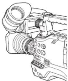
natural_image
Line drawing of a DSLR camera with lens and external frame (no text or symbols)3 Place the flange back adjustment chart about 3 m from the lens and adjust the lighting on the chart to obtain an appropriate video output level.
- If the video level is too high, use the filters or the shutter.
4 Loosen the F.f (Flange focus) ring clamping screw.
F.b (Flange back) may be indicated on some lenses.
5 Set the zoom ring to the telephoto position, either manually or by electric drive.
6 Aim the lens at the flange back adjustment chart and turn the distance ring to bring the chart into focus.
7 Set the zoom ring to the wide-angle position and turn the F.f ring to bring the chart into focus.
- While focusing, take care not to move the distance ring.
8 Repeat Steps 5 to 7 until the lens is in focus at both the telephoto and wide-angle positions.
9 Firmly tighten the F.f ring clamping screw.
White Shading Compensation
The camera can use DEFAULT (fixed value) and three user adjustable functions (USER1, USER2, USER3) to store white shading compensation data.
Select SHADING SELECT in the setting menu LENS SETUP screen to set compensation data. Selecting OFF turns off shading compensation.
Selecting White Shading Compensation Data
1 Open the setting menu LENS SETUP screen.
For details on menu operation, refer to [Using the menus] (page 116).
2 Use the JOG dial button to select SHADING SELECT, then press the JOG dial button.

3
Use the JOG dial button to select DEFAULT, USER1, USER2, USER3 or OFF and press the JOG dial button.
- To adjust the white shading, select USER1, USER2 or USER3.
- The USER1, USER2 or USER3 settings do not contain any compensation data by default.
- Store compensation data that suits KJ16ex7.7B IRSD PS12 and KJ16ex7.7B KRSD PS12 in DEFAULT. For lenses other than those above, perform the "White Shading Adjustment" described below.

White Shading Adjustment
Coloring may occur in the vertical direction near the open setting of the lens iris even when the white shading has been adjusted. This is an optical characteristic and not indicative of a failure.
1
Place the camera in the adjustment mode.
(1) Mount a lens on the camera.
- Do not forget to connect the lens cable.
(2) Turn off the electronic shutter and set the gain to L (0 dB).
(3) If the lens comes with an extender, disengage it.
(4) Open the setting menu LENS SETUP screen and select USER1, USER2 or USER3 under SHADING SELECT.
(5) Use the JOG dial button to select SHADING (USER), select YES and press the JOG dial button.
- The message "CHECK LUMINANCE LEVEL ZEBRA ON VF" appears.
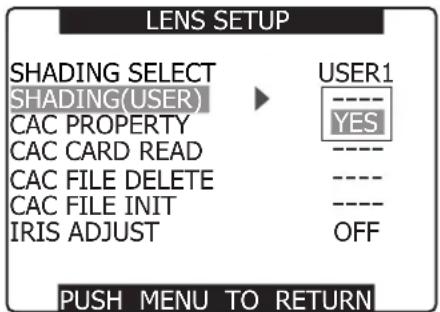
SHADING: USER1 SET OK? YES

2 Set the image.
(1) Shoot a solid white sheet of paper.
(2) Set the lens iris to manual and adjust the iris so that a zebra pattern fills the entire viewfinder screen.
- When the piece of paper is unevenly lit, the zebra pattern will not cover the entire screen. Adjust as required.
- Make sure that the white paper is not exposed to multiple light sources (example, fluorescent lighting or halogen lamps) of different color temperatures.
SHADING: USER1 SET OK?

- Adjust the white shading in sunlight, under halogen lamp light or other light source that does not flicker. Fluorescent light and mercury lamps tend to flicker and should not be used for this adjustment.
- Adjust the light source if the lens iris is out of the range between F4 and F11.
• Make sure the electronic shutter is set to off.
3 Adjust white and black balance.
(1) Set the WHITE BAL switch to A or B and use the AUTO W/B BAL switch to make an automatic white balance adjustment.
(2) Use the AUTO W/B BAL switch to make an automatic black balance adjustment.
(3) Again, use the AUTO W/B BAL switch to make an automatic white balance adjustment.
4 Repeat the operation in step 2-(2).
5 Adjust white shading.
(1) Use the JOG dial button to select YES and press the JOG dial button.
(2) The message "SHADING ACTIVE" appears on the screen during adjustment.
(3) When the adjustment ends after a few seconds, the message "SHADING OK" appears.
- When an error message such as "SHADING NG LEVEL OVER" or "SHADING NG LOW LIGHT" appears, adjust the iris.
- The adjusted value is automatically stored in memory (USER1, USER2, USER3).
6 If the lens is provided with an extender, turn on the extender function and perform steps 2 to 5 again.
- The white shading adjustment need not be readjusted when the extender is later turned off.
Setting Chromatic Aberration Compensation (CAC)
The CAC function of the camera corrects the registration error caused by the slight chromatic aberration that the lens cannot compensate for. This minimizes color bleeding into the surrounding image areas.
Lenses compatible with the CAC function whose CAC data is registered in the camera will automatically start CAC operation.
CAC data for the following four lenses have been registered in the camera as default values.
| Camera indication | Model numbers of compatible lenses |
| KJ16EX7.7B IRSD PS12 | KJ16ex7.7B IRSD PS12 |
| KJ16ex7.7B KRSD PS12 | |
| KJ21EX7.6B IRSD PS12 KJ21ex7.6B IRSD PS12 | |
| KJ10EX4.5B IRSD PS12 KJ10ex4.5B IRSD PS12 | |
| XA17X7.6BERM-M58B | XA17x7.6BERM-M58B |
| XA17x7.6BRM-M58B | |
- One of the lens model number appearing in the menu represents the lens group.
- The CAC function in this camera operates in horizontal direction only.
• The CAC function does not operate at +18 dB. - The CAC function may not operate normally in macro shooting.
- After the release of this camera, visit our Web site at the address given below for details on new lenses compatible with this function and any changes in this function.
Checking CAC Operating Status
Press the DISP/MODE CHK button when no menu is open.
- CAC is running if "CAC" appears in the upper right corner of the screen.

Checking CAC data number and CAC data during operation
1 Open the setting menu LENS SETUP screen.
For details on menu operation, refer to [Using the menus] (page 116).
2 Turn the JOG dial button to select CAC PROPERTY and select YES to open the CAC PROPERTY screen.
• The CAC property list appears.

■CAC Property
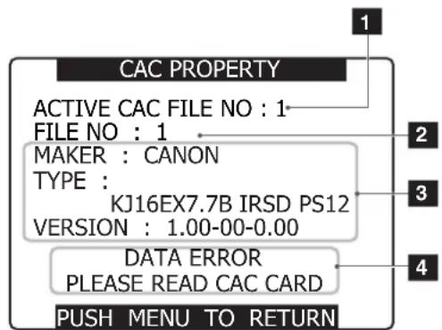
Current CAC data number
2 Data number of CAC you wish to check Turn the JOG dial to select.
3 CAC data specified by 2
4 Error messages
The file cannot be used if an error message appears. Initialize the CAC data or reload the CAC file from an SD card.
For details, see [Initializing CAC File] (page 97) or [Loading CAC File from an SD Card] (page 96).
Loading CAC File From an SD Card
1 Open the setting menu LENS SETUP screen.
For details on menu operation, refer to [Using the menus] (page 116).
2 Use the JOG dial button to select CAC CARD READ. Then select YES to open the CAC CARD READ screen.
LENS SETUP

PUSH MENU TO RETURN
3 Use the JOG dial button to select the CAC file to load. Then select YES and press the JOG dial button.
CAC CARD READ


PUSH MENU TO RETURN
CAC FILE NO:1 READ?
YES → PUSH DIAL
NO
CAC FILE READ
Deleting CAC File
1 Open the setting menu LENS SETUP screen.
For details on menu operation, refer to [Using the menus] (page 116).
2 Use the JOG dial button to select CAC FILE DELETE, select YES and press the JOG dial.
LENS SETUP

PUSH MENU TO RETURN
3 Use the JOG dial to select the CAC file to be deleted. Then select YES and press the JOG dial button.
“----” is indicated when deletion ends.
CAC FILE DELETE
1:KJ16EX7.7B IRSD PS12
2:KJ21EX7.6B IRSD PS12
3:KJ10EX4.5B IRSD PS12
4:XA17X7.6BERM-M58B

PUSH MENU TO RETURN
CAC FILE NO:1 DELETE?
YES → PUSH DIAL
NO
CAC FILE DELETE
• The camera can load up to 8 files.
When an attempt is made to load a new file while 8 files have already been loaded, "READ NG CAC FILE FULL" appears. To load new file, delete an existing file before loading the new file. For details, see [Deleting CAC File] (page 96).
- "READ NG FORMAT ERROR" indicates the file cannot be used and will not be loaded. Make sure the file is in a format the camera supports and that the file on the SD card is not corrupted.
Initializing CAC File (Returning Data to Their Factory Defaults)
1 Open the setting menu LENS SETUP screen.
For details on menu operation, refer to [Using the menus] (page 116).
2 Use the JOG dial button to select CAC FILE INIT. Then select YES to display the confirmation screen.
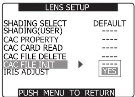
3 Select YES in the confirmation screen and press the JOG dial button.
- "CAC FILE INIT PROCESSING COMPLETED" is displayed to indicate that initialization is completed.
- The LENS SET UP screen appears after completion.
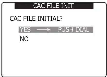
This operation deletes all files and returns the four CAC files to their factory defaults.
Preparing for Audio Input
Take the following steps to prepare the camera for connecting audio input devices.
When Using the Front Microphone
The AJ-MC200G microphone kit (optional) includes a microphone that can be mounted on the camera.
1 Open the microphone holder.

2 Mount the microphone and tighten the clamping screw.

3 Connect the microphone cable to the MIC IN jack on the camera.

4 Set the AUDIO IN switch to [FRONT] depending on the audio channel to be recorded.

When Using Audio Devices
1 Connect the audio device to the AUDIO IN jack with the XLR cable.
2 Set the AUDIO IN switch to [REAR] for the channel to which the XLR cable is connected.
3 Set the LINE/MIC/+48V selector switch on the rear panel to [LINE].

Attaching Accessories
Mounting the Camera on a Tripod
When mounting the camera on a tripod, use the tripod adapter supplied with the camera.
1 Mount the tripod adapter on the tripod.

Select an appropriate hole in the adapter, taking into account the center of gravity of the camera and tripod adapter combined.
Also, make sure that the diameter of the selected hole matches the diameter of the pan head screw.
2 Mount the camera on the tripod adapter.
- Slide the camera forward along the grooves until you hear a "click".

natural_image
Line drawing of a video camera and a tripod-mounted device (no text or symbols)Removing the Camera from the Tripod Adapter
While holding the red lever down, move the black lever in the direction of the arrow, and slide the camera backward to remove it.

natural_image
Pure mechanical component diagram without any text, numbers, or symbolsRed Lever
Black Lever
If the tripod adapter pin does not return to its original position after the camera has been removed, hold the red lever down and move the black lever in the direction of the arrow again, in order to return the pin to its original position.
Please note that the camera cannot be mounted if the pin remains in the center.
Attaching the Shoulder Strap
To detach the shoulder strap, first open the hooks, then detach the strap.

Make sure that the shoulder strap is securely attached.
Attaching the Rain Cover
When using the SHAN-RC700 Rain Cover

Attaching the FRONT AUDIO LEVEL Control Knob
If you use the FRONT AUDIO LEVEL control frequently, attach the accessory knob so that it can be easily operated.

Remove the screw in the center of the FRONT AUDIO LEVEL control, and attach the accessory knob using the screw (included). When attaching the knob, be sure to align the marks on the control with the marks on the knob.
Connecting the AJ-RC10G Extension Controller
- Some functions can be remote-controlled when the AJ-RC10G extension control unit (optional) is connected to the camera.
- When the AJ-RC10G is connected, the camera automatically enters remote control mode after the power switches of both the camera and the AJ-RC10G are turned ON.
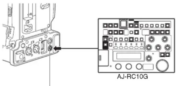
REMOTE connector
- Be sure to turn OFF both the camera and the AJ-RC10G power switches before connecting or disconnecting the controller cable.
- If RC DATA SAVE (AJ-RC10G) is set to OFF, the camera-related setting values, which have been adjusted or set using the AJ-RC10G, will be cancelled when the camera power switch is turned OFF. Also, the setting values cannot be written to an SD memory card. However, the menu settings performed using the AJ-RC10G can be written to an SD memory card. Next time the AJ-RC10G is connected, the setting values will return to the AJ-RC10G settings.
- If RC DATA SAVE (AJ-RC10G) is set to ON, the values adjusted or set using the AJ-RC10G are retained, even after the camera power switch is turned OFF.
- The USER switch on the camera does not function when the AJ-RC10G is connected.
- Refer to the Operating Instructions of the AJ-RC10G incurred in the supplied CD-ROM.
Chapter6
Manipulating Clips with Thumbnails
A clip is a data group that includes the images and voices created from one shooting session, together with additional information such as text memos and meta data.
The following manipulations can be performed using the cursor and SET buttons, while checking the images displayed on the LCD monitor:
● Play back, delete and repair clips
- Add or delete a shot mark and text memo on the clip thumbnail.
● Format P2 cards and SD memory cards.
●Upload the clip meta data from an SD memory card.
Thumbnail Operations
Thumbnail Overview
Thumbnail screens are configured as follows:

THUMBNAIL

OPERATION

PROPERTY
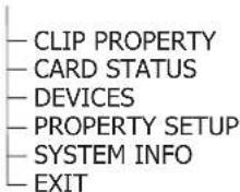
META DATA

- Thumbnail screens are not output from the SDI OUT/COMPONENT OUT connectors.
Thumbnail Screen
Press the MODE button to engage the MCR mode and open the thumbnail screen on the LCD monitor. When switching is done from the regular screen display to the thumbnail screen display, all the clips will be displayed on the thumbnail screen.
Pressing the thumbnail menu button in the thumbnail screen moves the pointer to the setting menu providing access to allow thumbnail menu functions.

1 Slot number
- The number of the slot with the P2 card containing the selected clip is indicated here. (The number appears in yellow.)
- If a clip extends over the P2 cards in two or more slots, numbers will appear in yellow.
- The slot number is surrounded by a pink border when a DIR location error or life end-up occurs.
2 Thumbnails
This is where the initial images of the clips are displayed.
3 Thumbnail display status
The types of clips displayed as thumbnails appear in this area.
4 Clip numbers
- The clips are displayed in the order in which they were shot.
- Clips in the wrong recording format or clips which cannot be played back for other reasons are shown in red.
- To play clips indicated by the red numbers, set the format for the REC FORMAT/MCR FORMAT option on the RECORDING SETUP setting menu to the format 6 below.
- Clips on the playlist which have been edited and copied using the AJ-SPD850 memory card recorder or other such unit and which have more than one format (DVCPRO/DV or DVCPRO50) are shown in red, and these clips cannot be played back even when the REC FORMAT item has been set.
5 Menu display
- This is where the menu items are displayed.
- When EXIT is selected and the SET button is pressed, the menu display is cleared, and the original screen is restored.
6 Recording mode/format display
This is where the recording mode and format of the recorded images are displayed.
7 Indicators
M (Shot mark):
This indicates that a clip has a shot mark.
W (Wide):
This indicates that a clip has been recorded in the 16:9 aspect ratio (wide screen). (480i/576i recording)
! (Incomplete clip):
This indicator appears when the recording of a clip extends over two P2 cards and one of the cards is not found in the slot.
X (Defective clip):
- This indicator appears for a clip whose recording was defective because the power was cut off during the recording process, for instance.
- Clips indicated by the yellow defective clip indicator can be repaired.
- Clips indicated by the red defective clip indicator cannot be repaired so delete them. If a clip cannot be deleted, first back up its data, and then format the P2 card. Clips in the wrong format are indicated by ( ? ) instead.
V (Voice memo):
This indicates that a clip has a voice memo. (You cannot perform recording/playback with this camera.)
T (Text memo):
This indicates that a clip has a text memo.
E (Edit copy):
This indicates that this is an edit copy clip. (You cannot perform editing with this camera.)
P (Proxy):
This indicates that a proxy has been added and recorded. (You cannot perform recording with this camera.)
For detailed explanations on V, T, E, and P, refer to the Operating Instructions supplied with the devices used to record or edit the voice memo, text memo, edit copy clip, and proxy respectively.
8 Duration display
This displays the duration of the selected clip.
Selecting Thumbnails
Multiple thumbnails can be randomly selected in the thumbnail screen.
1 Use the cursor buttons to move the pointer (yellow frame) to the desired clip and press the SET button.
- The frame around the selected thumbnail changes to a blueframe. Press the SET button again to deselect the clip.
2 Additional clips can be selected by repeating Step 1.
It is possible to display only the selected thumbnails in the thumbnail screen for playback. Please refer to [Switching the Thumbnail Display] (page 105) for more information.

Switching the Thumbnail Display
The display can be switched so that only those clips matching the specified conditions are displayed in the thumbnail screen.
1 Press the MODE button to enter the MCR mode.
- The thumbnail screen appears on the LCD monitor.
2 Press the thumbnail menu button to open the menu.

3 Move the pointer to THUMBNAIL and select with the SET button.
• The setting sub-menu appears.
- Select the desired item to specify the type of thumbnail display.
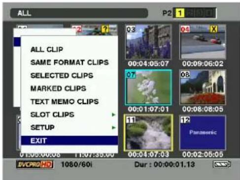
- ALL CLIP:
Display all clips.
• SAME FORMAT CLIPS:
The clips in the same recording (or MCR) format are displayed.
- SELECTED CLIPS:
Display randomly selected clips.
- MARKED CLIPS:
Display clips with shot marks attached.
• TEXT MEMO CLIPS:
Clips with text memos are displayed. Thumbnails at text memo positions, time codes (TC), total number of memos and the current order of the clips are displayed.
- SLOT CLIPS:
Display clips recorded in the P2 card inserted in the specified slot.
- SETUP:
Various setup operations are performed.
- EXIT:
The previous screen reappears.
■To delete a text memo
1 Select THUMBNAIL → TEXT MEMO CLIPS, move the cursor to the text memo to be deleted and press the SET button.
2 Move the cursor to the text memo thumbnail to be deleted.
3 Press the MENU button to open the setting menu and choose OPERATION → DELETE.
• The text memo is deleted.
- Pressing the thumbnail button and selecting EXIT returns the pointer to the top of the thumbnail display.
Setting the Thumbnail Display Mode
The thumbnail display mode can be customized to suit your preferences.
1 Press the MODE button to enter the MCR mode.
- The thumbnail screen appears on the LCD monitor.
2 Press the thumbnail menu button to open the menu.
3 Select THUMBNAIL → SETUP.

- MARKER IND.:
Shows or hides (ON/OFF) the shot mark indicator. The factory setting is ON (indication).
• TEXT MEMO IND.:
Shows or hides (ON/OFF) the text memo indicator. The factory setting is ON (indication).
• VOICE MEMO IND.:
Shows or hides (ON/OFF) the voice memo indicator. The factory setting is ON (indication).
• WIDE IND.:
Shows or hides (ON/OFF) the wide indicator. The factory setting is ON (indication).
- PROXY IND.:
Shows or hides (ON/OFF) the proxy indicator. The factory setting is ON (indication).
• DATA DISPLAY:
The time display field of the clip offers a choice of Time Code (TC), User Bits (UB), Shooting Time (TIME) or Shooting Date (DATE)/Shooting Time and Date (DATE TIME). The factory setting is Time Code.
- DATE FORMAT:
You can specify the display order for the shooting date as either Year/Month/Day (YMD), Month/Day/Year (MDY) or Day/Month/Year (DMY). The factory setting is Year/Month/Day.
This setting is reflected in the recording date shown in the clip property and the shooting date shown when DATE is selected under the item DATA DISPLAY.
- THUMBNAIL SIZE:
For the size of thumbnails displayed on one screen, either LARGE (3 × 2 thumbnails displayed) or NORMAL (4 × 3 thumbnails displayed) can be selected. The factory default value is NORMAL.
• THUMBNAIL INIT:
Return the above thumbnail display settings to default.
Move the cursor to this option, and press the SET button. Select "YES" when the confirmation screen is displayed.
- EXIT:
Returns to the previous menu.
Clip Operations
Playing Back Clips
1 Press the MODE button to enter the MCR mode.
- The thumbnail screen appears on the LCD monitor.
2 Use the cursor buttons to move the pointer over the desired clip.
3 Press the PLAY button, and the clip under the pointer will be played back on the LCD monitor.
- After playback of the clip under the pointer, subsequent clips are played back in order, according to when they were shot. The thumbnail screen returns after the last clip has been played back.
- When playing back clips, it is not necessary to "select" the clips (blue frames around the thumbnails).
- Clips with clip numbers displayed in red cannot be played.
4 During playback, pressing the REW button starts 4× speed reverse playback, and the FF button starts 4× speed fast playback.
- Press the PLAY button to return to normal playback.
5 During clip playback, pressing the STILL button will temporarily stop (pause) the process.
- During a pause, pressing the REW button moves the pause position to the beginning of the clip.
- Pressing the REW button again moves the pause position to the beginning of the previous clip.
- During a pause, pressing the FF button moves the pause position to the beginning of the next clip. (Holding down the FF button displays the last image in the last clip. "EOS" appears at this time.)
6 Pressing the STOP button during clip playback stops the playback and returns the display to the thumbnail screen.
When playback is stopped, the position of the pointer remains on the clip that was being played back, regardless of where the playback started.
Shot Mark
A shot mark can be added to a clip thumbnail to distinguish this clip from the others.
1 Press the MODE button to enter the MCR mode.
- The thumbnail screen appears on the LCD monitor.
2 Use the cursor buttons to move the pointer over the clip to which you want to attach a shot mark.
3 Press the USER button to which the shot mark function has been assigned.
- Use the setting menu SW MODE screen to assign the SHOT MARK function to a USER button.

natural_image
Technical line drawing of a car dashboard and steering wheel (no text or symbols)USER MAIN, USER1 and USER2 buttons
4 A shot mark will be attached to the clip thumbnail under the pointer.
- To delete a shot mark, reposition the pointer over the clip and press the Shot Mark button.
When adding a shot mark to (or deleting the shot mark from) a clip recorded across multiple P2 cards, do this with all these P2 cards inserted into P2 card slots.
Deleting Clips
1 Press the MODE button to enter the MCR mode.
- The thumbnail screen appears on the LCD monitor.
2 Use the cursor buttons to move the pointer over the clip you want to delete, and press the SET button.
- Press the SET button to select the clip.
3 Press the thumbnail menu button to select OPERATION → DELETE from the menu bar.
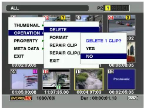
4 A screen to confirm the delete operation appears. Use the cursor buttons and the SET button to select YES.
- The clip is deleted.
- All selected clips (in blue-green frames) are deleted by this operation.
After selecting multiple clips and during deletion with "CANCEL" indication displayed, pressing the SET button stops the deletion operation in the middle.
Restoring Clips
Restores clips that are defective as a result of sudden poweringdown during recording, or removal of the P2 card being accessed.
- Only those clips with yellow corrupt clip markers can be restored. Delete the clips with red corrupt clip markers. If the clip cannot be deleted, format the P2 card.
- During restoration of the clips, however, the defective-clip indicator may change from yellow to red, resulting in inability to restore the clips.
1 Press the MODE button to enter the MCR mode.
- The thumbnail screen appears on the LCD monitor.
2 Use the cursor buttons to move the pointer over the clip you want to restore (defective clips are indicated by corrupt clip marks), and press the SET button.
- Press the SET button to select the clip.
3 Press the thumbnail menu button to select OPERATION → REPAIR CLIP from the menu bar.
To restore a bad clip generated during loop recording, select REPAIR CLIP (LOOP). Clip repair may take some time.
4 The confirmation window appears. Use the cursor buttons and the SET button to select YES.
Setting of Clip Meta Data
Information such as the name of person who shot the video, the name of the reporter, the shooting location, or a text memo can be read from the SD memory card, and can be recorded as Clip Meta Data.
Reading Clip Meta Data (metadata upload)
1 Insert the SD memory card that contains the Clip Meta Data (metadata upload file).
2 Press the MODE button to enter the MCR mode.
- The thumbnail screen appears on the LCD monitor.
3 Press the thumbnail menu button to open the menu.
4 Select META DATA → LOAD from the menu bar.

5 Names of metadata upload files stored on the SD memory card are displayed.
- Select the desired files using the cursor buttons, and choose YES. Upload starts.
- Uploaded metadata is retained even if the power is turned off.
For confirmation of uploaded data, see [Confirmation of Metadata Upload] (page 115).
Clip metadata content
- Clip Meta Data includes the following items: Underlined items can be set by reading the metadata upload file on the SD memory card.
- Other items are set automatically during shooting. Using the latest update version of P2 viewer, metadata upload files can be written to SD memory cards using a PC.
- Download the latest update version of P2 viewer from the following URL and install it to your PC: https://eww.pavc.panasonic.co.jp/pro-av/ See [Memory Card Usage] (page 83).
The file which was edited by except P2 viewer is displayed as "UNKNOWN DATA", and may not be read.
• GLOBAL CLIP ID:
Displays the global clip ID, which indicates the shooting status of the clip.
- USER CLIP NAME:
Displays the clip name specified by the user.*
* If the metadata upload file does not contain any data, the global clip ID serves as the USER CLIP NAME. The USER CLIP NAME recording method is selectable. For more information, see [Selecting the USER CLIP NAME recording method] (page 110).
• VIDEO:
Displays [FRAME RATE] (frame rate of the clip), [PULL DOWN], and [ASPECT RATIO].
• AUDIO:
[SAMPLING RATE] (sampling frequency of recorded sound) and [BITS PER SAMPLE] (digitized bit[s] of recorded sound). Corresponds to CH1-CH4.
- ACCESS:
Displays [CREATOR] (person who recorded the clip), [CREATION DATE] (date when the clip was recorded), [LAST UPDATE DATE] (date of the latest update of the clip), and [LAST UPDATE PERSON] (person who made the latest update of the clip).
• DEVICE:
Displays [MANUFACTURER] (name of the device manufacturer), [SERIAL NO.] (serial number of the device) and [MODEL NAME] (model name of the device).
- SHOOT:
Displays [SHOOTER] (name of the person who shot the video), [START DATE] (start date of shooting), [END DATE] (end date of shooting), and [LOCATION/ALTITUDE/LONGITUDE/LATITUDE/SOURCE/PLACE_NAME] (altitude, longitude, latitude, and source of the information and name of the location).
- SCENARIO*:
Displays [PROGRAM NAME], [SCENE NO.], and [TAKE NO.].
* Be sure to enter PROGRAM NAME when entering SCENARIO. It is not possible to record only the SCENE NO or TAKE NO.
- NEWS:
Displays [REPORTER] (name of the reporter), [PURPOSE] (purpose of shooting), and [OBJECT] (object of shooting).
- MEMO\*:
Displays the NO. (memo number), OFFSET (frame position from the beginning of the clip), PERSON (name of the person who recorded the text memo), and TEXT (memo content).
* Be sure to enter TEXT when entering MEMO. It is not possible to record only PERSON.
“*” appears when text cannot be correctly displayed, for example, when Japanese or Chinese metadata is displayed in English or when the metadata contains characters that cannot be rendered in English.
To set whether or not the uploaded metadata is recorded
Set ON/OFF by selecting META DATA → RECORD.
Selecting the USER CLIP NAME recording method
Select META DATA → USER CLIP NAME from the menu bar to select the recording method. Two options are available: TYPE1 and TYPE2.
●TYPE1 (factory setting)
| USER CLIP NAME to be recorded | |
| If clip metadata has been read in Up | loaded data |
| If no clip metadata has been read in or if the setting for recording clip metadata has been turned off | Same as GLOBAL CLIP ID (UMID data) |
●TYPE2
| USER CLIP NAME to be recorded | |
| If clip metadata has been read in | Uploaded data + COUNT value* |
| If no clip metadata has been read in or if the setting for recording clip metadata has been turned off | Same as CLIP NAME |
* The COUNT value is indicated as a four-digit number. The COUNT value is incremented each time a new clip is captured if clip metadata has been read in and TYPE2 has been selected as the recording method.
The COUNT value can be reset using the following procedure.
Select METADATA > PROPERTY > USER CLIP NAME. Select "COUNT RESET" with the cursor and press the SET button to reset the COUNT value to 1.

When a P2 card with a memory capacity of 8 GB or more is used in this unit and a one-time continuous recording exceeds the prescribed duration (approx. 5 minutes for DVCPRO HD, approx. 10 minutes for DVCPRO50, or approx. 20 minutes for DVCPRO/DV) or when a one-time recording extends over more than one P2 card, the recording concerned will automatically be undertaken as a separate clip. At this time, each clip will be provided with its own COUNT value.
■ Example of recording (DVCPRO50) a clip on one P2 card:

■ Example of recording a clip on two P2 cards:
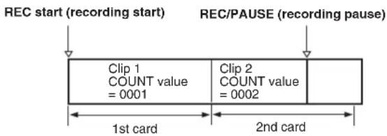
If the clip thumbnails are displayed as shown in the example above or their properties are indicated using a P2 device, the thumbnail and COUNT value of clip 1 will be displayed.
Clear the uploaded metadata
Select META DATA → INITIALIZE, and press the SET button. Select "YES" when the confirmation screen is displayed.
Displaying loaded metadata
Select METADATA → PROPERTY and press the SET button to display the metadata recorded in this unit.
Formatting P2 and SD Memory Cards
Formatting a P2 Card
1 Press the MODE button to enter the MCR mode.
- The thumbnail screen appears on the LCD monitor.
2 Press the thumbnail menu button to open the menu.
3 From the menu bar, select OPERATION → FORMAT.
- The following screen appears. Select the slot number for the P2 card you want to format.
- Select EXIT if formatting is not required.

4 Use the CURSOR and SET buttons to select YES in the screen that confirms whether you want to format the card.
• The selected P2 card is formatted.
Formatting SD memory cards
SD memory cards can also be formatted from the thumbnail screen. With an SD memory card inserted into the camera-recorder, perform the following operation:
1 Press the MODE button to enter the MCR mode.
- The thumbnail screen appears on the LCD monitor.
2 Press the thumbnail menu button to open the menu.
3 Select OPERATION → FORMAT.
- The following screen appears. Select "SD-CARD".
- Select "EXIT" if formatting is not required.
![ALL P2 1 5[0]1 THUMBNAIL OPERATION DELETE FORMAT REPAIR CLIP REPAIR CLIP(U) EXIT SLOT1 SLOT2 SLOT3 SLOT4 0:09:06:02 0:08:08:05 SD CARD EXIT DVCPRO 1080/60i Dur : 00:00:00:10](/content/2026/06/1254106/images/3dcc0b01d51c0da6b8d19e66ade6634378a54872e63df9a21a54c925f2344ec2.jpg)
4 Use the CURSOR and SET buttons to select YES in the screen that confirms whether you want to format the card.
• The SD memory card is formatted.
- SD memory cards can also be formatted from the menu screen.
For more information, see [Formatting, Writing and Reading an SD memory card] (page 78). - For an SDHC card, the space of 32 KB is already used.
Properties
The clip's properties and the P2 card's status are displayed.
Clip Property
Select PROPERTY → CLIP PROPERTY. The following screen appears.

1 Clip number
2 Thumbnail
3 Slot number
4 Clip information
Various indicators that have been added to the clip and also various kinds of data are displayed. (Appears if the P2 card is writeprotected)
- CLIP NAME: Clip name
- START TC: Time code value when recording started
- START UB: User's bit value when recording started
• DATE: Date when the recording was made
• TIME: Time when recording started
• DURATION: Clip length
• V_FORMAT: Video signal format
• FRAME RATE: Playback frame rate
• REC RATE: Recording frame rate
This display appears when recording using a setting for the FRAME RATE item on the SCENE FILE screen other than the default during 720P/24PN or 720P/30PN recording operation.
5 Clip metadata
The video and audio formats, videographer information and other detailed data are displayed here. The audio format is only indicated for 1 to 4CH. Use the CURSOR button to select the item and press the SET button. (For details on the clip metadata, see [Setting of Clip Meta Data] (page 109).)
P2 Card Status Display
P2 Card Status Display Settings
Select PROPERTY → CARD STATUS to set the desired indication mode (remaining free space or used memory capacity) for the P2 card status display.
1 Press the MODE button to enter the MCR mode.
- The thumbnail screen appears on the LCD monitor.
2 Press the thumbnail menu button to open the menu.
3 Select PROPERTY → PROPERTY SETUP → P2CARD CAP.
- The following screen appears. Select the P2 card status display settings from the P2 CARD CAP menu option.

- REMAIN:
Show remaining free space on the P2 card as the P2 card status display.
• USED:
Show used memory capacity on the P2 card as the P2 card status display.
The factory setting for this function is REMAIN.
Contents of P2 Card Status Display Settings
Select PROPERTY → CARD STATUS. The following screen appears.
■When "REMAIN" is selected:

1 Write-protect Mark
The mark 🔍 appears if the P2 card is write-protected.
2 P2 Card Status (remaining free space)
The remaining memory capacity of the P2 card is indicated by a bar graph and percentage. The bar graph indicator moves to the left as the remaining free space decreases.
The following indications may appear, depending on the card status:
- FORMAT ERROR:
An unformatted P2 card is inserted.
• NOT SUPPORTED:
An unsupported card is inserted in the camera.
- NO CARD:
P2 cards are not inserted.
Press the SET button to view the following data for the card in the selected slot (indicated in yellow numbers).
• BRAND: maker name
• MODEL NO.: model number
• SERIAL NO.: serial number
- USER ID: user ID
- WARNING: DIR ENTRY NG (DIR location error) RUN DOWN CARD (life)
3 P2 Card Remaining Capacity/Total Capacity
Displays the P2 card remaining capacity and total capacity in minutes.
The total of the remaining memory capacity for each P2 card that is displayed may not match the actual total remaining memory capacity for the P2 cards because only the figure in minute is displayed.
4 Total remaining memory capacity for all cards
- Displays the total remaining free space for all 4 slots.
Please note that the remaining capacity of a write-protected P2 card is not included in the total remaining capacity.
- When REC FUNCTION (RECORDING SETUP) is set to LOOP, the total remaining memory capacity for all cards indicates the minimum guaranteed recording time for the loop recording. When “REMAIN” is selected, the value of this indication is smaller than the actual possible recording time.
5 Warning card mark
The mark 📁 appears when the following P2 cards are inserted.
- DIR ENTRY NG
- RUN DOWN CARD
Use the 2 P2 card status to check the nature of the warning.
■When "USED" is selected:
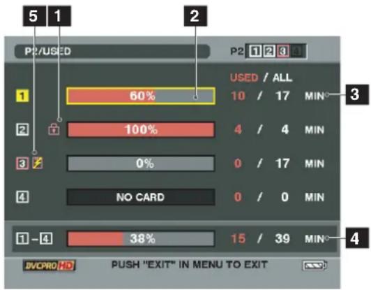
1 Write-protect Mark
The mark 📋 appears if the P2 card is write-protected.
2 P2 Card Status (used memory capacity)
The used memory capacity of the P2 card is indicated by a bar graph and a percentage figure. The bar graph indicator moves to the right as the used memory capacity increases.
The following indications may appear, depending on the card status:
- FORMAT ERROR:
An unformatted P2 card is inserted.
• NOT SUPPORTED:
An unsupported card is inserted in the camera.
- NO CARD:
P2 cards are not inserted.
Press the SET button to view the following data for the card in the selected slot (indicated in yellow numbers).
• BRAND: maker name
• MODEL NO.: model number
• SERIAL NO.: serial number
- USER ID: user ID
- WARNING: DIR ENTRY NG (DIR location error) RUN DOWN CARD (life)
3 P2 Card memory capacity/Total Capacity
Displays the used memory capacity on a P2 card and the total capacity, in minutes.
Because fractions are truncated, the figure shown for used memory capacity on a P2 card may differ from the figure for total capacity.
The used memory capacity of a write-protected P2 card is displayed as 100%.
4 Total used memory capacity for all slots
- Displays the total used memory capacity for all 4 slots.
- When REC FUNCTION (RECORDING SETUP) is set to LOOP, this indication shows the minimum guaranteed recording time for the loop recording. When "USE" is selected, the value of this indication is greater than the actual used memory capacity.
5 Warning card mark
The mark 📁 appears when the following P2 cards are inserted.
- DIR ENTRY NG
• RUN DOWN CARD
Use the 2 P2 card status to check the nature of the warning.
SD memory card Status Display
The status display enables a confirmation of the SD memory card formatted condition, available memory capacity etc.
Select PROPERTY → DEVICES → SD CARD.
■Screen showing SD memory card data

- SD STANDARD: This indicates whether the SD memory card was formatted in compliance with the SD standard (SUPPORTED/NOT SUPPORTED).
For an SDHC card, the space of 32 KB remains used even after being formatted.
• USED: Space used
- BLANK: Space available
• TOTAL: Total space
• NUMBER OF CLIPS: Number of clips
- PROTECT: This indicates that the SD memory card is write protected.
Confirmation of Metadata Upload
- The contents of the metadata upload file that is read from the SD memory card can be checked.
- Select META DATA → PROPERTY. The following screen appears:
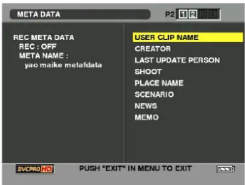
For more information on each item, see [Setting of Clip Meta Data] (page 109).
- The META NAME is the meta data name written in the meta data upload file, and is not recorded in the clip.
Chapter7 Menu Operations
Viewfinder and LCD Menus
Using the menus
Use the setup menus to change the settings to suit the scenes you are shooting or what you are recording.
- If the thumbnail menu is displayed, press the THUMBNAIL button to release the display.
- The menu items indicated in the blue characters cannot be used.
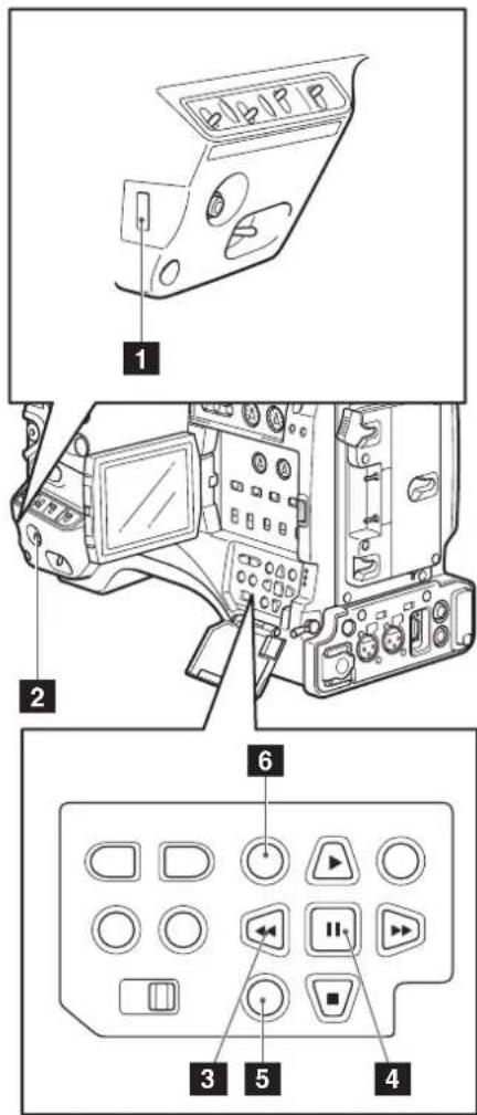
1 JOG dial button
2 MENU button
3 CURSOR buttons
4 SET button
5 Thumbnail menu button
6 Thumbnail button
1 When the unit is in other than playback or recording mode, press the MENU button.
- Hold down the front menu button for 1 second or longer.
- The function screen appears in the viewfinder and on the LCD screen.
CAMERA MENU
1.SCENE FILE
2.CAMERA SETUP
3.SW MODE
4.RECORDING SETUP
5. AUDIO SETUP
6. OUTPUT SEL
7.DISPLAY SETUP
8.VF!LED
PUSH MENU TO EXIT
2 Use the JOG dial button (or the Up and Down cursor buttons) to highlight the function you want to change.
CAMERA MENU
1.SCENE FILE
2.CAMERA SETUP
3.SW MODE
4.RECORDING SETUP
5. AUDIO SETUP
6. OUTPUT SEL
7.DISPLAY SETUP
8.VF!LED
PUSH MENU TO EXIT
3 Press the JOG dial button (or the SET button) to display the items.
SW MODE
MID GAIN
HIGH GAIN
W.BAL.PRESET
USER MAIN SPOTLIGHT
USER1
USER2

6dB
12dB
3.2K
GAIN:18dB
SLOTSEL
PUSH MENU TO RETURN
4 Use the JOG dial button (or the Up and Down cursor buttons) to highlight the item you want to change.
SW MODE

PUSH MENU TO RETURN
5 Use the JOG dial button (or the SET button) to change the setting value.
SW MODE
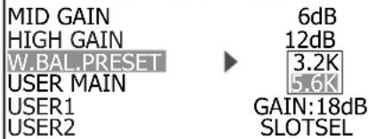
PUSH MENU TO RETURN
6 To change other settings, repeat steps 4 and 5.
- When you finish, press the MENU button to return to the function screen.
7 To change other functions, repeat steps 2 to 5.
- To exit the function screen and return to the normal screen, press the MENU button again.
Direct close function
When the MENU button is pressed and held down after making a menu setting closes the setting menu screen without first returning to the previous setting menu.
Initializing the menu settings
The menu settings contain both the user file settings and the scene file settings. You can initialize them separately.
To initialize the user file (i.e. all the settings other than the scene file settings)
Select INITIAL in USER FILE of the OTHER FUNCTIONS screen. The current menu settings of user file will return to the factory settings.
To initialize the scene file
From the 6 scene files, select the one you want to initialize with the SCENE FILE dial. Then in the SCENE FILE screen, LOAD/SAVE/INIT, select INITIAL.
The settings for only the selected scene file are returned to the factory settings.
• This does not effect the other scene files.
Setup menu structure
Camera (CAM) mode menu

flowchart
graph TD
    A["CAMERA MENU"] --> B["SCENE FILE"]
    A --> C["CAMERA SETUP"]
    A --> D["SW MODE"]
    A --> E["RECORDING SETUP"]
    A --> F["AUDIO SETUP"]
    A --> G["OUTPUT SEL"]
    A --> H["DISPLAY SETUP"]
    A --> I["VF ! LED"]

    B --> J["LOAD/SAVE/INIT"]
    B --> K["OPERATION TYPE"]
    B --> L["FRAME RATE"]
    B --> M["SYNCRO SCAN"]
    B --> N["DETAIL LEVEL"]
    B --> O["V DETAIL LEVEL"]
    B --> P["DETAIL CORING"]
    B --> Q["CHROMA LEVEL"]
    B --> R["CHROMA PHASE"]
    B --> S["COLOR TEMP Ach"]
    B --> T["COLOR TEMP Bch"]
    B --> U["MASTER PED"]
    B --> V["A.IRIS LEVEL"]
    B --> W["NEWS GAMMA"]
    B --> X["GAMMA"]
    B --> Y["KNEE"]
    B --> Z["MATRIX"]
    B --> AA["SKIN TONE DTL"]
    B --> AB["V DETAIL FREQ"]
    B --> AC["NAME EDIT"]

    C --> AD["ASPECT CONV"]
    C --> AE["SETUP*"]

    D --> AF["MID GAIN"]
    D --> AG["HIGH GAIN"]
    D --> AH["W.BAL.PRESET"]
    D --> AI["USER MAIN"]
    D --> AJ["USER1"]
    D --> AK["USER2"]

    E --> AL["REC FORMAT"]
    E --> AM["480I (576I) REC MODE"]
    E --> AN["REC FUNCTION"]
    E --> AO["ONE SHOT TIME"]
    E --> AP["INTERVAL TIME"]
    E --> AQ["START DELAY"]
    E --> AR["PREREC MODE"]
    E --> AS["TC MODE*"]
    E --> AT["TC IN UB REGEN"]
    E --> AU["UB MODE"]

    F --> AV["FRONT VR CH1"]
    F --> AW["FRONT VR CH2"]
    F --> AX["MIC LOWCUT CH1"]
    F --> AY["MIC LOWCUT CH2"]
    F --> AZ["MIC LOWCUT CH3"]
    F --> BA["MIC LOWCUT CH4"]
    F --> BB["LIMITER CH1"]
    F --> BC["LIMITER CH2"]
    F --> BD["LIMITER CH3"]
    F --> BE["LIMITER CH4"]
    F --> BF["AUTO LEVEL CH3"]
    F --> BG["AUTO LEVEL CH4"]
    F --> BH["25M REC CH SEL"]
    F --> BI["TEST TONE"]
    F --> BJ["F.MIC POWER1"]
    F --> BK["F.MIC POWER2"]
    F --> BL["R.MIC POWER"]
    F --> BM["F.MIC CH1 LEVEL"]
    F --> BN["F.MIC CH2 LEVEL"]
    F --> BO["R.MIC CH1 LEVEL"]
    F --> BP["R.MIC CH2 LEVEL"]
    F --> BQ["HEADROOM"]
    F --> BR["MONITOR MODE"]

    G --> BS["ZEBRA DETECT"]
    G --> BT["MARKER"]
    G --> BU["SAFETY ZONE"]
    G --> BV["DATE/TIME"]
    G --> BW["LEVEL METER"]
    G --> BX["ZOOM"]
    G --> BY["CARD/BATT"]
    G --> BZ["P2CARD REMAIN"]
    G --> CA["OTHER DISPLAY"]
    G --> CB["LCD BACKLIGHT"]
    G --> CC["LCD SET"]
    G --> CD["SELF SHOOT"]
    G --> CE["DOWNCON MODE"]
    G --> CF["DISPLAY ASPECT"]
    G --> CG["MENU BACK"]

    H --> DH["GAIN"]
    H --> DI["WHITE"]
    H --> DJ["SHUTTER"]
    H --> DK["FILTER"]
    H --> DL["EXTENDER"]

    I --> DM["* 59.94 Hz only"]
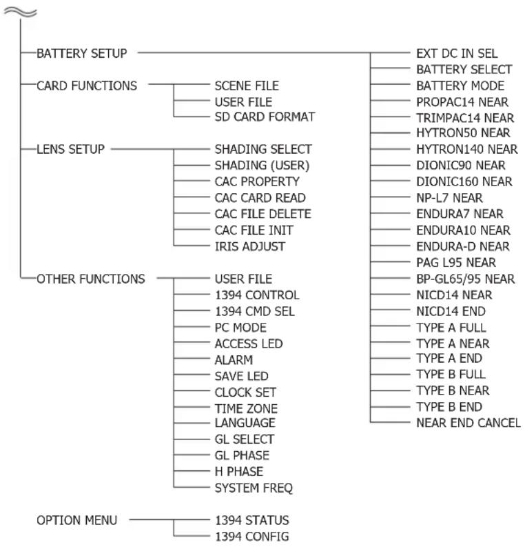
flowchart
graph TD
    A["~"] --> B["BATTERY SETUP"]
    A --> C["CARD FUNCTIONS"]
    A --> D["LENS SETUP"]
    A --> E["OTHER FUNCTIONS"]
    A --> F["OPTION MENU"]

    B --> G["SCENE FILE"]
    B --> H["USER FILE"]
    B --> I["SD CARD FORMAT"]

    C --> J["SHADING SELECT"]
    C --> K["SHADING (USER)"]
    C --> L["CAC PROPERTY"]
    C --> M["CAC CARD READ"]
    C --> N["CAC FILE DELETE"]
    C --> O["CAC FILE INIT"]
    C --> P["IRIS ADJUST"]

    D --> Q["USER FILE"]
    D --> R["1394 CONTROL"]
    D --> S["1394 CMD SEL"]
    D --> T["PC MODE"]
    D --> U["ACCESS LED"]
    D --> V["ALARM"]
    D --> W["SAVE LED"]
    D --> X["CLOCK SET"]
    D --> Y["TIME ZONE"]
    D --> Z["LANGUAGE"]
    D --> AA["GL SELECT"]
    D --> AB["GL PHASE"]
    D --> AC["H PHASE"]
    D --> AD["SYSTEM FREQ"]

    E --> AE["EXT DC IN SEL"]
    E --> AF["BATTERY SELECT"]
    E --> AG["BATTERY MODE"]
    E --> AH["PROPAC14 NEAR"]
    E --> AI["TRIMPAC14 NEAR"]
    E --> AJ["HYTRON50 NEAR"]
    E --> AK["HYTRON140 NEAR"]
    E --> AL["DIONIC90 NEAR"]
    E --> AM["DIONIC160 NEAR"]
    E --> AN["NP-L7 NEAR"]
    E --> AO["ENDURA7 NEAR"]
    E --> AP["ENDURA10 NEAR"]
    E --> AQ["ENDURA-D NEAR"]
    E --> AR["PAG L95 NEAR"]
    E --> AS["BP-GL65/95 NEAR"]
    E --> AT["NICD14 NEAR"]
    E --> AU["NICD14 END"]
    E --> AV["TYPE A FULL"]
    E --> AW["TYPE A NEAR"]
    E --> AX["TYPE A END"]
    E --> AY["TYPE B FULL"]
    E --> AZ["TYPE B NEAR"]
    E --> BA["TYPE B END"]
    E --> BB["NEAR END CANCEL"]
MCR mode menu

flowchart
graph TD
    A["MCR MENU"] --> B["RECORDING SETUP MCR FORMAT"]
    A --> C["OUTPUT SEL CMPNT/SDI SEL"]
    C --> D["SDI METADATA"]
    C --> E["SDI EDH"]
    A --> F["DISPLAY SETUP"]
    F --> G["DATE/TIME"]
    F --> H["LEVEL METER"]
    F --> I["CARD/BATT"]
    F --> J["P2CARD REMAIN"]
    F --> K["OTHER DISPLAY"]
    F --> L["LCD BACKLIGHT"]
    F --> M["LCD SET"]
    F --> N["DOWNCON MODE"]
    F --> O["LCD ASPECT"]
    F --> P["MENU BACK"]
    A --> Q["BATTERY SETUP"]
    Q --> R["EXIT DC IN SEL"]
    Q --> S["BATTERY SELECT"]
    Q --> T["BATTERY MODE"]
    Q --> U["PROPAC14 NEAR"]
    Q --> V["TRIMPAC14 NEAR"]
    Q --> W["HYTRON50 NEAR"]
    Q --> X["HYTRON140 NEAR"]
    Q --> Y["DIONIC90 NEAR"]
    Q --> Z["DIONIC160 NEAR"]
    Q --> AA["NP-L7 NEAR"]
    Q --> AB["ENDURA7 NEAR"]
    Q --> AC["ENDURA10 NEAR"]
    Q --> AD["ENDURA-D NEAR"]
    Q --> AE["PAG L95 NEAR"]
    Q --> AF["BP-GL65/95 NEAR"]
    Q --> AG["NICD14 NEAR"]
    Q --> AH["NICD14 END"]
    Q --> AI["TYPE A FULL"]
    Q --> AJ["TYPE A NEAR"]
    Q --> AK["TYPE A END"]
    Q --> AL["TYPE B FULL"]
    Q --> AM["TYPE B NEAR"]
    Q --> AN["TYPE B END"]
    Q --> AO["NEAR END CANCEL"]
    A --> P
    P --> Q
    Q --> R
    R --> S
    R --> T
    R --> U
    R --> V
    R --> W
    R --> X
    R --> Y
    R --> Z
    R --> AA
    R --> AB
    R --> AC
    R --> AD
    R --> AE
    R --> AF
    R --> AG
    R --> AH
* 59.94 Hz only
■ Marks used in the list
: Indicates that the item can be set in the CAMERA mode.
: Indicates that the item can be set in the MCR mode.
/ : Indicates that the item can be set in both CAMERA and MCR modes.
SCENE FILE screen
| LOAD/SAVE/INIT | Saves, loads and initializes scene files.●----(No operation), LOAD (Load), SAVE (Save), INITIAL (Initialize)Switches the shutter and frame rate operation to the video type or film type.●VIDEO CAM:SYNCRO SCAN is set in 1/n increments. The frame rate is dependent on the RECFORMAT. Slow shutter speeds are enabled. Time code is displayed at 30 frames except at 24PN. (25 frames at 50 Hz) |
| OPERATION TYPE | ●FILM CAM:SYNCRO SCAN is displayed as an angle. FRAME RATE can be used to vary the frame rate. Slow shutter speeds are disabled. The time code indication is fixed at 24 hour display. (25 frames at 50 Hz)Selects the shooting interval and exposure time when 720P and FILM CAM TYPE is selected. The default values for the REC FORMAT 720/60, 720/30 and 720/24 are fixed at 60P, 30P and 24P, respectively. |
| FRAME RATE | ●59.94Hz SYSTEMDEFAULT, 12, 18, 20, 22, 24, 26, 30, 32, 36, 48, 60●50Hz SYSTEMDEFAULT, 12, 18, 20, 23, 25, 27, 30, 32, 37, 48, 50Adjusts the synchro scan shutter speed used for shooting images on a TV screen, etc. Turn and hold the JOG dial button (operation button) upwards or downwards to increase the speed at which the set values change.●When VIDEO CAM is selected as the OPERATION TYPE option setting:●60P/60i: 1/60.0 ... 1/249.8 |
| SYNCRO SCAN | ●50P/50i: 1/50.0 ... 1/248.9●30P/30PN: 1/30.1 ... 1/48.0 ... 1/249.8●25P/25PN: 1/25.0 ... 1/48.0 ... 1/248.9●24P/24PA/24PN: 1/24.0 ... 1/48.0 ... 1/249.8●When FILM CAM is selected as the OPERATION TYPE option setting:●The shutter speed is displayed as an angle such as “180.0d.”●10.0 deg ... 180.0 deg ... 360.0 deg (the angle can be changed in increments of 0.5 degrees) |
| DETAIL LEVEL | Adjusts the level of the image outline correction (in the horizontal and vertical directions).●Adjustable range: -7 ... 0 ... + 7 |
| V DETAIL LEVEL | Adjusts the level of outline correction in the vertical direction.●Adjustable range: -7 ... 0 ... + 7 |
| DETAIL CORING | Adjusts the level of noise reduction of the detail signal.●Adjustable range: -7 ... 0 ... + 7Set to – for a clearer image. Noise increases slightly. Set to + to reduce noise. |
| CHROMA LEVEL | Adjusts the chroma level.●Adjustable range: -7 ... 0 ... + 7 |
| CHROMA PHASE | Makes fine adjustments to the chroma phase.●Adjustable range: -7 ... 0 ... + 7 |
| COLOR TEMP Ach | Makes fine adjustments to the color temperature (after white balance adjustment of Ach).●Adjustable range: -7 ... 0 ... + 7 |
| COLOR TEMP Bch | Makes fine adjustments to the color temperature (after white balance adjustment of Bch).●Adjustable range: -7 ... 0 ... + 7 |
| MASTER PED | Adjusts the black master pedestal that serves as the video reference.●Adjustable range: -100 ... 0 ... + 100 |
| A. IRIS LEVEL | Sets the desired AUTO IRIS level.●Adjustable range: -10 ... 0 ... + 10 |
| Item Description of settings (Items in bold are factory settings.) | |
| NEWS GAMMA* CAM | Selects the news gamma curve. (Only valid for 1080i/60i, 50i, 720/50P, 50P, 480/60i and 576/50i)●ON, OFF |
| GAMMA* CAM | Selects the gamma curves other than the news gamma curve.●HD NORM: This gamma setting is suitable for HD shooting.●LOW: Makes a mellow image using the gamma curve which has a gentle incline in lowbrightness curve. The contrast sharpens.●SD NORM: This is the standard gamma curve for SD shooting.●HIGH: Expands the tone of dark parts and makes a brighter image using the gamma curve which has a sharp incline in lowbrightness curve. The contrast softens.●B.PRESS: Makes the contrast sharper than LOW.●CINELIKE D: Makes a cinema-like image.●CINELIKE V: Makes a cinema-like image with emphasized contrast.When you select CINELIKE gamma, we recommend to set the lens aperture lower than normal image level (approximately 1/2) to enjoy the full benefit of the function. |
| KNEE CAM | To avoid overexposure, select the compression level (knee point) of the high intensity video signals received through CCD.●LOW: Low setting (Compression starts at approx. 80 %.)●MID: Medium setting (Compression starts at approx. 90 %.)●HIGH: High Setting (Compression starts at approx. 100 %.)This setting cannot be changed when GAMMA is enabled and CINELIKE gamma is selected. |
| MATRIX CAM | Selects the MATRIX table suitable for the desired color expression during shooting.●NORM1: Suitable for shooting in the open air or under a halogen lamp.●NORM2: Suitable for brighter colors than the NORM1 mode.●FLUO: Suitable for shooting under fluorescent light indoors.●CINELIKE: Suitable for cinema-like image. |
| SKIN TONE DTL CAM | Sets the skin tone details. Select ON to reduce the skin tone details and soften the skin tone.●ON, OFF |
| V DETAIL FREQ CAM | Sets the vertical detail for shooting in the progressive mode at 480/24P, 24PA 30P 576/25P.●THIN: Makes the detail thin.●MID: Makes the detail slightly thicker.●THICK: Makes the detail thicker.When images were shot in the progressive mode in which the vertical detail is set as “THIN” or “MID” and are played on a monitoring television (60i interlace), you will see flickers caused on horizontal lines and almost horizontal oblique lines. When playing back images in the progressive mode or when editing images or performing other postprocessing, images with a higher resolution will be obtained with the THIN or MID setting than with the THICK setting. |
| NAME EDIT CAM | Edits the name of the selected scene file you have selected with the scene file dial. |
* The gamma curve is fixed to CINELIKE V at a gain setting of 18 dB.
CAMERA SETUP screen
| Item Description of settings (Items in bold are factory settings.) | |
| ASPECT CONVCAM | Selects the aspect ratio of the image you record in 480i/576i (SD mode) format. This item cannot be selected when the 1080i or 720P recording format is used.SIDE CROP (Side crop), LETTER BOX, SQUEEZE |
| SETUP(only when set to 59.94 Hz)CAM | Selects the setup level for the 480i video signal. The SETUP menu setting for playback is enabled:%: Setup is switched to 0 % for both camera output and recording.%7.5%A: Video output is set to 7.5% while D terminal output, SDI output and recording are set to 0%. |
SW MODE screen
| Item Description of settings (Items in bold are factory settings.) | |
| MID GAINCAM | Sets the gain value assigned to the M position of the GAIN switch.●0 dB, 3 dB, 6 dB, 9 dB, 12 dB |
| HIGH GAINCAM | Sets the gain value assigned to the H position of the GAIN switch.●0 dB, 3 dB, 6 dB, 9 dB, 12 dB |
| W.BAL.PRESETCAM | Sets the color temperature assigned to the PRST position of the WHITE BAL switch.●3.2 K / 5.6 K |
| USER MAINCAM | Selects the function assigned to the USER MAIN button.●REC CHECK: Performs Rec Check.●SPOTLIGHT: Auto iris control for the spotlight ON/OFF●BACKLIGHT: Auto iris control for the backlight compensation●BLACKFADE: Blackfade●WHITEFADE: Whitefade●GAIN: 18 dB:Press the button to set the gain value to 18 dB. This setting takes effect with the 60i and 60P recording formats only. It is not valid when the recording frame rate is less than 22 fps or when the slow shutter mode (1/15) is established.When the gain value is set to 18 dB or set from 18 dB to another value, the image can be disordered for a moment.TEXT MEMO: Text memo recordingSLOT SEL: Selects one of the P2 card slots.SHOT MARK: Shot mark recordingLVL METER: Displays the level for channels other than those set in the menu.MARKER: Displays markers.LCD REV: Displays an upside down and reversed image on the LCD. |
| USER1CAM | Selects the function assigned to the USER1 button. The settings are the same as USER MAIN above.Factory setting: BACKLIGHT |
| USER2CAM | Selects the function assigned to the USER2 button. The settings are the same as USER MAIN above.Factory default: LVL METER |
RECORDING SETUP screen
| Item Description of settings (Items in bold are factory settings.) | |
| REC FORMATCAM | Selects the recording format for P2 card.●59.94Hz System: 1080i/60i, 1080i/30P, 1080i/24P, 1080i/24PA, 720P/60P, 720P/30P, 720P/24P, 720P/30PN, 720P/24PN, 480i/60i, 480i/30P, 480i/24P, 480i/24PA●50 Hz System: 1080i/50i, 1080i/25P, 720P/50P, 720P/25P, 720P/25PN, 576i/50i, 576i/25P |
| 480i (576i)REC MODECAM | Selects the 480i (576i) recording mode.Enabled during SD mode recording.●DVCPRO50 / DVCPRO/DV |
| REC FUNCTIONCAM | Selects the special recording mode.●NORMAL, INTERVAL, ONE SHOT, LOOP |
| ONE SHOT TIMECAM | Selects the one-shot recording time.●1F, 2F, 4F, 8F, 16F, 1s |
| INTERVAL TIMECAM | Sets the interval time (INT) for interval recording (INTERVAL REC).●2F, 4F, 8F, 16F, 1s, 2s, 5s, 10s, 30s, 1m, 5m, 10m |
| START DELAYCAM | Sets the START delay time for INTERVAL REC and ONE SHOT REC.●ON, OFF |
| PREREC MODECAM | Sets PRE RECORDING to ON or OFF. (Fixed to 3 seconds for HD and 7 seconds for SD)●ON, OFF |
| TC MODE(only when set to 59.94 Hz)CAM/MCR | Selects the time code correction mode when recording the time code output by the internal time code generator.●DF: Uses the drop frame mode.●NDF: Uses the non-drop frame mode.The non-drop frame mode is used when a frame rate of 24P, 24PA, or 24PN is selected in a recording format regardless of TC MODE setting. |
| TC IN UB REGENCAM | Selects the user bits to be recorded when recording signals from a device connected to the TC IN connector.●ON: Records the user bits of the signal input to the TC IN connector.●OFF: Records the user bits selected in the menu option UB MODE.●Setting this option to ON prioritizes the input signal over the settings made in the menu option UB MODE.●No user bits are recorded when the input signal does not contain any user bits.●Settings of the menu option UB MODE are used when no signal is input to the TC IN connector. |
| UB MODECAM/MCR | Set the content for user information.●USER: Records the information of user.●TIME: Records the time at recording.●DATE: Records the date at recording.●TCG: Records the values of the time code generator.●FRM. RATE: Records the frame rate information for frame conversion.** 0 *****a cb da: Checking information for user informationb: Frame sequence No.●0 to 4 are displayed in 24P/24P (ADV) mode.●F is displayed in the modes other than above.c: Frame rates●Frame rate (60/30/24)●I/P ID●Conversion data●Frame rate coefficientd: Recording management data●Frame update information●REC START/STOP informationWhen connecting the HD SDI output to an external device (with HD SDI input) for backing up data, set UB MODE to FRM.RATE to enable control of recording start/stop from the camera.The external device has to be set up when automatic recording is desired. For details, refer to the Operating Instructions supplied with the device. |
| MCR FORMATMCR | Selects playback or 1394 input format.●When operating at 59.94 Hz: 1080i/60i, 720P/60P, 720P/30PN, 720P/24PN, 480i/60i●When operating at 50 Hz: 1080i/50i, 720P/50P, 720P/25PN, 576i/50i720P/30PN, 24PN and 25PN are available only for playback. |
| 480i (576i)MCR MODEMCR | Selects the 480i (576i) playback mode, or 1394 input format.●DVCPRO50 / DVCPRO/DV |
| F-RUN TC SLAVEMCR | Selects whether slave-locked time code input via the 1394 connector is used or not when the TCG switch is set to F-RUN.●1394: Records with the slave-locked time code via the 1394 connector.●OFF: Records with the time code selected by the TC MODE item or the TCG switch. |
| 1394 UB REGENMCR | Selects the user bits to be recorded when recording signals from a device connected to the 1394 connector.●ON: Records the user bits of the signal input to the 1394 connector.●OFF: Records the user bits selected in the menu option UB MODE.·Setting this option to ON prioritizes the input signal over the settings made in the menu option UB MODE.·No user bits are recorded when the input signal does not contain any user bits.·The UB MODE settings are used when no signal is input to the TC IN connector. |
AUDIO SETUP screen
| Item Description of settings (Items in bold are factory settings.) | |
| FRONT VR CH1CAM | Selects the function of the FRONT AUDIO LEVEL control of CH1 input.●FRONT: The front control controls FRONT1 and FRONT2 inputs.●REAR: The FRONT AUDIO LEVEL control controls REAR1 input.●ALL: The FRONT AUDIO LEVEL control controls both FRONT1 and REAR1 inputs.●OFF: The FRONT AUDIO LEVEL control does not control the input signal.This control is disabled when the AUDIO SELECT CH1 switch is set to AUTO. |
| FRONT VR CH2CAM | Selects the function of the FRONT AUDIO LEVEL control of CH2 input.●FRONT: The FRONT AUDIO LEVEL control controls FRONT2 input.●REAR: The FRONT AUDIO LEVEL control controls REAR2 input.●ALL: The FRONT AUDIO LEVEL control controls both FRONT2 and REAR2 inputs.●OFF: The FRONT AUDIO LEVEL control does not control the input signal.This control is disabled when the AUDIO SELECT CH2 switch is set to AUTO. |
| MIC LOWCUT CH1CAM | Turns on and off the CH1 microphone lowcut filter.●ON, OFF |
| MIC LOWCUT CH2CAM | Turns on and off the CH2 microphone lowcut filter.●ON, OFF |
| MIC LOWCUT CH3CAM | Turns on and off the CH3 microphone lowcut filter.●ON, OFF |
| MIC LOWCUT CH4CAM | Turns on and off the CH4 microphone lowcut filter.●ON, OFF |
| LIMITER CH1CAM | Turns on and off the CH1 limiter.●ON, OFF |
| LIMITER CH2CAM | Turns on and off the CH2 limiter.●ON, OFF |
| LIMITER CH3CAM | Turns on and off the CH3 limiter.●ON, OFF |
| LIMITER CH4CAM | Turns on and off the CH4 limiter.●ON, OFF |
| AUTO LEVEL CH3CAM | Selects the method for selecting CH3 level.●ON: Automatically controls CH3 level.●OFF: Enables dial control of CH3 level via dial. |
| AUTO LEVEL CH4CAM | Selects the method for selecting CH4 level.●ON: Automatically controls CH4 level.●OFF: Enables dial control of CH4 level via dial. |
| 25M REC CH SELCAM | Selects the audio channels to be recorded in the DVCPRO and DV formats.●2CH: Only recorded on CH1 and CH2.●4CH: Recorded on channels 1 to 4. |
| TEST TONECAM | Selects the test signal.●OFF: Disables test tone output.●NORMAL: Outputs test tones to channels 1, 2, 3 and 4 when the OUTPUT/AUTO KNEE selector switch is set to BARS and the AUDIO IN switch CH1 is set to FRONT1.●ALWAYS: Outputs test tones to channels 1, 2, 3 and 4 when the OUTPUT/AUTO KNEE selector switch is set to BARS.●CH SEL: Outputs test tones to channels selected by setting AUDIO IN switch CH1 to FRONT1 or switch CH2 to FRONT with the OUTPUT/AUTO KNEE selector switch set to BARS.When NORMAL or CH SEL is selected, setting the AUDIO IN switch CH1 to FRONT2 will not output a test tone. |
| F.MIC POWER1CAM | Turns on and off the phantom power supply for the front microphone connected to CH1.●ON, OFF |
| F.MIC POWER2CAM | Turns on and off the phantom power supply for the front microphone connected to CH2.●ON, OFF |
| R.MIC POWERCAM | Turns on and off the phantom power supply for the rear microphone.●ON, OFF |
| F.MIC CH1 LEVELCAM | Selects the input level for the front microphone connected to CH1.●-40 dB, -50 dB, -60 dB |
| F.MIC CH2 LEVELCAM | Selects the input level for the front microphone connected to CH2.●-40 dB, -50 dB, -60 dB |
| R.MIC CH1 LEVELCAM | Selects the input level for the rear microphone connected to CH1.●-50 dB, -60 dB |
| R.MIC CH2 LEVELCAM | Selects the input level for the rear microphone connected to CH2.●-50 dB, -60 dB |
| HEADROOMCAM | Sets the headroom (standard level).●59.94Hz System: 18 dB, 20 dB●50 Hz System: 18 dB, 20 dB |
| MONITOR MODECAM | Switches speaker and earphone audio delay.●LIVE: No audio delay●RECORDING: Recorded (delayed) audio |
OUTPUT SEL screen
| Item Description of settings (Items in bold are factory settings.) | |
| CMPNT/SDI SELCAM/MCR | Selects D or SDI connector.●59.94Hz system: AUTO, 1080i, 480i●50 Hz system: AUTO, 1080i, 576iIf this item is set to AUTO, the REC FORMAT setting will be applied. |
| SDI METADATA CAM/MCR | Turns on and off metadata superimposition onto the SDI signal.●ON, OFF |
| SDI EDH CAM/MCR | Turns on and off EDH superimposition onto the SD-SDI signal.●ON, OFF |
| TC VIDEO SYNCRO CAM | Selects whether to delay time code output.●TC IN: Outputs the input from the TC IN connector without delay.●VIDEO: Outputs the time code with delay according to the output video. |
DISPLAY SETUP screen
| Item Description of settings (Items in bold are factory settings.) | |
| ZEBRA DETECTCAM | Selects the brightness level of the left-leaning zebra patterns on the screen.●50 %, 55 %, 60 %, 65 %, 70 %, 75 %, 80 %, 85 %, 90 %, 95 %, 100 %, 105 % |
| MARKERCAM | Turns on or off the center marker display.●ON, OFFSet this item to ON to display the marker. The brightness status is also displayed. |
| SAFETY ZONECAM | Sets SAFETY ZONE.●OFF, 90 %, 4:3 |
| DATE/TIME CAM/MCR | Sets whether to display the date and time on the screen and whether to output from the VIDEO IN/OUT jack.●OFF: The date and time are not displayed.●TIME: The time is displayed.●DATE: The date is displayed.●TIME&DATE: The time and date are displayed. |
| LEVEL METER CAM/MCR | Select ON to display the audio level meter.●ON, OFF |
| ZOOM CAM | Turns zoom value display on and off.●ON, OFFDisplays zoom values between Z00 to Z99. |
| CARD/BATT CAM/MCR | Turns on and off card and battery remaining level.●ON, OFF |
| P2CARD REMAIN CAM/MCR | Switches the indication of remaining P2 memory card capacity.●TOTAL: Indicates total remaining capacity of all cards.●ONE-CARD: Indicates the remaining capacity of the card that is being recorded. |
| OTHER DISPLAYCAM/MCR | Select how much information to display on the screen.●OFF, PARTIAL, ALL |
| LCD BACKLIGHTCAM/MCR | Adjusts the backlight of the LCD monitor. Select HIGH for brighter backlight.●HIGH, NORMAL |
| LCD SETCAM/MCR | Adjusts the display level of the images on the LCD monitor.●LCD COLOR LEVEL, LCD BRIGHTNESS ,LCD CONTRASTSelect to set respective value using the right and left cursor keys. |
| SELF SHOOTCAM | Selects the LCD mirror mode for self-portrait shooting. Select MIRROR to reverse left and right at self-portrait shooting.●NORMAL, MIRROR |
| DOWNCON MODECAM/MCR | Switches down-conversion output mode.●SIDE CROP: Side-crop mode●LETTER BOX: Letter-box mode●SQUEEZE: Squeeze mode |
| LCD ASPECTCAM/MCR | Selects the aspect ratio of the LCD monitor and the viewfinder. Operates when the recording format is set to the SD format.●AUTO: Changes automatically to the appropriate ratio according to the recording or play mode information.●4:3: Fixed at 4:3.Black bands appear at the top and bottom of the screen when images are displayed at a 16:9 aspect ratio. No parts of the images are missing. |
| MENU BACKCAM/MCR | Selects whether to lower the transparency of the background to make menu text easier to read.●ON: Lowers background transparency. This function is not available for synchro scan and LCD SET pages.●OFF: Sets a background transparency of 100%. |
VF! LED screen
| Item Description of settings (Items in bold are factory settings.) | |
| GAINCAM | Sets the conditions (gain value) for lighting the “!” symbol LED in the viewfinder.●w/o0 dB: other than 0 dB●OFF: Off |
| WHITECAM | Sets the conditions (white balance value) for lighting the “!” symbol LED in the viewfinder.●PRST: Preset●OFF: Off |
| SHUTTERCAM | Sets the conditions (shutter status) for lighting the “!” symbol LED in the viewfinder.●ON, OFF |
| FILTERCAM | Sets the conditions (filter status) for lighting the “!” symbol LED in the viewfinder.●NG: Abnormal●No1: No1●w/o No1: other than No 1●OFF: Off |
| EXTENDERCAM | Sets the conditions (extender status) for lighting the “!” symbol LED in the viewfinder.●ON, OFF |
BATTERY SETUP screen
| Item Description of settings (Items in bold are factory settings.) | |
| EXT DC IN SELCAM/MCR | Selects external DC power supply type.●AC ADPT: AC adapter●BATTERY: battery |
| BATTERY SELECTCAM/MCR | Selects battery type.●PROPAC14, TRIMPAC14, HYTRON50, HYTRON140, DIONIC90, DIONIC160, NP-L7, ENDURA7, ENDURA10, ENDURA-D, PAG L95, BP-GL65/95, NICD14, TYPE A, TYPE B |
| BATTERY MODECAM/MCR | Near end setting●AUTO: Automatically selects one of the following battery types selected in BATTERY SELECT. PROPAC14, TRIMPAC14, HYTRON50, HYTRON140, DIONIC90, DIONIC160, NP-L7, ENDURA7, ENDURA10, ENDURA-D, PAG L95, BP-GL65/95●MANUAL: Manually enter near end voltage. |
| PROPAC14 NEARCAM/MCR | Sets near end voltage for PROPAC14 (Adjustable in 0.1 V units).●Adjustable range: 11.0 ... 13.9 ... 15.0 |
| TRIMPAC14 NEARCAM/MCR | Sets near end voltage for TRIMPAC14 (Adjustable in 0.1 V units).●Adjustable range: 11.0 ... 13.6 ... 15.0 |
| HYTRON50 NEARCAM/MCR | Sets near end voltage for HYTRON50 (Adjustable in 0.1 V units).●Adjustable range: 11.0 ... 13.7 ... 15.0 |
| HYTRON140 NEARCAM/MCR | Sets near end voltage for HYTRON140 (Adjustable in 0.1 V units).●Adjustable range: 11.0 ... 13.1 ... 15.0 |
| DIONIC90 NEARCAM/MCR | Sets near end voltage for DIONIC90 (Adjustable in 0.1 V units).●Adjustable range: 11.0 ... 13.5 ... 15.0 |
| DIONIC160 NEARCAM/MCR | Sets near end voltage for DIONIC160 (Adjustable in 0.1 V units).●Adjustable range: 11.0 ... 13.0 ... 15.0 |
| NP-L7 NEARCAM/MCR | Sets near end voltage for NP-L7 (Adjustable in 0.1 V units).●Adjustable range: 11.0 ... 13.3 ... 15.0 |
| ENDURA7 NEARCAM/MCR | Sets near end voltage for ENDURA7 (Adjustable in 0.1 V units).●Adjustable range: 11.0 ... 13.4 ... 15.0 |
| ENDURA10 NEARCAM/MCR | Sets near end voltage for ENDURA10 (Adjustable in 0.1 V units).●Adjustable range: 11.0 ... 13.3 ... 15.0 |
| ENDURA-D NEARCAM/MCR | Sets near end voltage for ENDURA-D (Adjustable in 0.1 V units).●Adjustable range: 11.0 ... 13.5 ... 15.0 |
| PAG L95 NEARCAM/MCR | Sets near end voltage for PAG L95 (Adjustable in 0.1 V units).●Adjustable range: 11.0 ... 13.5 ... 15.0 |
| BP-GL65/95 NEARCAM/MCR | Sets near end voltage for BP-GL65/95 (Adjustable in 0.1 V units).●Adjustable range: 11.0 ... 13.3 ... 15.0 |
| NICD14 NEARCAM/MCR | Sets near end voltage for NICD14 (Adjustable in 0.1 V units).●Adjustable range: 11.0 ... 13.9 ... 15.0 |
| NICD14 ENDCAM/MCR | Sets end voltage for NICD14 (Adjustable in 0.1 V units).●Adjustable range: 11.0 ... 13.5 ... 15.0 |
| TYPE A FULLCAM/MCR | Sets full voltage for TYPE A (Adjustable in 0.1 V units).●Adjustable range: 12.0 ... 15.7 ... 17.0 |
| TYPE A NEARCAM/MCR | Sets near end voltage for TYPE A (Adjustable in 0.1 V units).●Adjustable range: 11.0 ... 13.5 ... 15.0 |
| TYPE A ENDCAM/MCR | Sets end voltage for TYPE A (Adjustable in 0.1 V units).●Adjustable range: 11.0 ... 12.8 ... 15.0 |
| TYPE B FULLCAM/MCR | Sets full voltage for TYPE B (Adjustable in 0.1 V units).●Adjustable range: 12.0 ... 16.0 ... 17.0 |
| TYPE B NEARCAM/MCR | Sets near end voltage for TYPE B (Adjustable in 0.1 V units).●Adjustable range: 11.0 ... 13.1 ... 15.0 |
| TYPE B ENDCAM/MCR | Sets end voltage for TYPE B (Adjustable in 0.1 V units).●Adjustable range: 11.0 ... 12.5 ... 15.0 |
| NEAR END CANCELCAM/MCR | Selects whether to cancel battery near end warning or not.●ON/OFFWhen set to ON, the the flashing alarm and tally lamps can be stopped by pressing the DISP/MODE CHK button. |
CARD FUNCTION (SD memory card setting) screen
| Item Description of settings (Items in bold are factory settings.) | |
| SCENE FILECAM | Reads/writes a scene file from/onto the SD memory card.●READ: Loads the selected scene file (1 to 4) values from an SD memory card.●WRITE: Saves the current scene file (1 to 4) settings to the SD memory card.●TITLE RELOAD: Reloads title list. |
| USER FILECAM | Reads/writes user files (files other than scene files) from/onto the SD memory card.●READ: Reads the user file settings (1 to 4) stored on the SD memory card.●WRITE: Saves the current user file settings (1 to 4) to the SD memory card.●TITLE RELOAD: Reloads title list. |
| SD CARD FORMATCAM | Formats the SD memory cards or not.●----: Does not format.●YES: Format. |
LENS SETUP screen
| Item Description of settings (Items in bold are factory settings.) | |
| SHADING SELECT CAM | Selects one of the following shading compensation parameters.●DEFAULT: Standard lens setting●USER1: User setting 1●USER2: User setting 2●USER3: User setting 3●OFF: Sets shading compensation to OFF. |
| SHADING (USER) CAM | Selects whether to set shading parameters to SHADING SELECT USER1, 2, and 3 or not.●----: Off●YES: OnThis item is disabled when SHADING SELECT is set to DEFAULT or OFF. |
| CAC PROPERTY CAM | Displays currently used CAC file number and content of CAC file currently loaded in the camera.●----: Off●YES: On |
| CAC CARD READ CAM | Selects whether to load CAC file from the SD memory card or not.●----: Off●YES: On |
| CAC FILE DELETE CAM | Selects whether to display a list of CAC file loaded in the camera and to delete the selected CAC file.●----: Off●YES: On |
| CAC FILE INIT CAM | Returns the CAC file loaded in the camera to its factory default setting.●----: Off●YES: On |
| IRIS ADJUST CAM | Forcibly sets the iris.●OFF/F2.8/F16 |
OTHER FUNCTIONS screen
| Item Description of settings (Items in bold are factory settings.) | |
| USER FILECAM/MCR | Saves users files on, loads users files from the storage area of the camera (EEPROM), and initializes the storage area.●----: Off (no operation)●LOAD: Loads the settings in a user file previously stored on the storage area.●SAVE: Saves the user file updated settings on the storage area.●INITIAL: Returns the user settings in the user file to their factory defaults.· After a LOAD or INITIAL operation, turn the POWER switch off and then back on again to make the new settings available.· An INITIAL operation does not change the setting of the menu option TIME ZONE. |
| 1394CONTROLCAM | Sets the control method for backup recording using a backup unit connected to the 1394 terminal.●OFF: The backup unit is not controlled.●EXT: The backup unit can be controlled by the START/STOP button. The images shot by the camera recorder are recorded by the backup unit. Note that the camera recorder does not record them.●BOTH: The images shot by the camera recorder are recorded by both the camera recorder and backup unit.●CHAIN: When the camera recorder's media approaches its end during shooting, the backup unit in the recording standby mode automatically starts recording images.When set to BOTH, direct shooting (function that automatically engages the CAMERA mode and starts shooting when pressing the START/STOP button in the MCR mode) starts camera recording but does not set a backup device to recording mode. |
| 1394CMD SELCAM | Sets how the REC START/STOP button works for the backup unit.●REC_P: This switches between recording and pause.●STOP: This switches between recording and stop.If the backup unit does not have a rec pause function, select STOP. |
| PC MODECAM/MCR | Selects the terminal for data transfer. (You cannot select USB and 1394 at the same time.)●USB DEVICE: Mode for sending files using the USB connector.●1394 DEVICE: Mode for sending files using the 1394 connector.●1394 HOST: Mode for copying files from the P2 card onto an external hard disk drive using the 1394 connector. |
| ACCESS LEDCAM/MCR | Enables or disables the access LED. The L-SIDE is the P2 card slot side.(ON: LEDs turn on and blink normally. OFF: LEDs always stay off.)●OFF L-SIDE: OFF R-SIDE: OFF●SLOT SIDE L-SIDE: ON R-SIDE: OFF●LCD SIDE L-SIDE: OFF R-SIDE: ON●BOTH L-SIDE: ON R-SIDE: ON |
| ALARMCAM | Turns the alarm function on and off.●ON, OFF |
| SAVE LEDCAM/MCR | Sets the SAVE lamp operation.●SAVE: Lights when the SAVE/STBY switch is set to SAVE.●P2CARD: Blinks when a warning message appears to indicate that there is little space left on a P2 card. |
| CLOCK SETCAM/MCR | Sets the camera-recorder's calendar.●----: Does not set●YES: Sets |
| TIME ZONECAM/MCR | Adds to or deducts from GMT the time value of -12:00 to +13:00 in 30-minute steps. (As an exception, you can set +12:45.)●0:00 |
| LANGUAGECAM/MCR | Sets the Menu language.●ENGLISH●JAPANESE●CHINESE |
| GL SELECTCAM | Determines which signal to lock on to.●SDI, COMPOSITE |
| GL PHASECAM | Determines whether to perform a 90H shift (ON) or not (OFF).●ON, OFF |
| H PHASECAM | Adjusts the phase.●-512 ~ 0 ~ +511 |
| SYSTEM FREQCAM/MCR | Switches the system frequency.●59.94 Hz, 50 Hz (AG-HPX500P)●59.94 Hz, 50 Hz (AG-HPX500E) |
OPTION MENU screen
This screen is displayed when you press the front MENU button after displaying the shooting status by pressing and holding down the DISP/MODE CHK button. Use this screen to confirm the connection status during nonlinear editing.
| Item Description of settings | |
| 1394 STATUSCAM/MCR | The 1394 status sub-screen is displayed.●FORMAT: format of the signal being input or output●RATE: transfer rate of the signal being input or output●60/50: system of the signal being input or output●CH: channel number being input or output●SPEED: transfer speed of the signal being input or output●STATUS: status of the signal being input or output via the IEEE 1394 digital interface●VIDEO: status of the video signal being input or output●AUDIO: status of the audio signal being input or output |
| 1394 CONFIGCAM/MCR | The 1394 expanded menu is displayed.●DFLT: Normally use the menu as displayed.1-255 |
Chapter8
Connecting to External Devices
Connecting to External Devices Using USB2.0 Port (PC mode)
By connecting the AG-HPX500P/E with an external PC using USB 2.0, the P2 card connected to the AG-HPX500P/E can be used as a mass storage device.
Procedures for establishing a connection with a PC
1 Connect the USB cable to the USB 2.0 port.
- The USB 2.0 cable is not included with AG-HPX500P/E. Please use a commercially available USB 2.0 cable (shield with a ferrite core).
- The camera supports USB cable lengths up to 5 meters. However, we recommend using a USB cable shorter than 3 meters.

natural_image
Line drawing of a handheld electronic device with ports and casing (no text or symbols)USB 2.0 port
2 Open the setting menu screen, and set the menu option PC MODE to USB DEVICE.
For details on menu operation, refer to [Using the menus] (page 116).
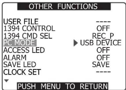
3 Press the MENU button to end menu operations.
4 Press the MODE button to turn on the MCR mode LED and keep the button held down.
- This lights the PC mode LED indicating that the unit is in the PC mode.
5 Edit data on the PC.
- For details, refer to the Operating Instructions supplied with the PC.
When you establish the USB connection for the first time, install the accessory P2 software for AG-HPX500P/E on the PC. Select AG-HPX500 for the USB driver during installation.
Refer to the Installation Manual for the details.
• A USB driver must be installed on the PC.
- The camera is only compatible with USB 2.0. Use a PC that supports USB 2.0.
- Only one AG-HPX500P/E at a time must be connected to the PC via USB.
- The P2 card must not be removed when it is connected via USB.
- While a USB connection is established, the P2 card's access LED should not be lit except when access is being carried out.
- Recording, playback and clip thumbnail operations cannot be performed when the PC MODE is set to USB DEVICE.
- Be sure to follow "Safe hardware removal" procedures on the PC when disconnecting the USB cable.
- "CONNECT" lights during USB connection. "USB DEVICE" appears at the center of the viewfinder.
- “DISCONNECT” appears when the devices are not correctly connected.
6 To exit the PC MODE, turn the POWER switch OFF.
Connecting to External Devices Using the IEEE1394 Connector (PC mode)
Connecting an external PC or hard disk to this unit via IEEE1394 makes it possible to use the P2 cards in this unit as mass storage.
Procedures for establishing a connection with a PC
1 Connect the IEEE1394 cable to the 1394 connector.
- An IEEE1394 cable is not supplied. Purchase a commercially available cable.
- Use a Macintosh computer running Apple® Mac OS® X in version 10.3 or later.
- This operation is not guaranteed under Windows®.
- Pay attention to cable connector orientation during connection.

3 Press the MENU button to end menu operations.
4 Press the MODE button to turn on the MCR mode LED and keep the button held down.
- This lights the PC mode LED indicating that the unit is in the PC mode.
5 Edit data on the PC.
- For details, refer to the Operating Instructions supplied with the PC.
- Do not remove P2 cards when using an IEEE1394 connection.
- Place the driver icon in the trash before replacing a card.
- Place all driver icons in the trash and check that the 1394DEVICE-DISCONNECT message appears before disconnecting the 1394 cable.
- Recording, playback and clip thumbnail operations cannot be performed when the PC MODE is set to 1394DEVICE.
• PC data cannot be saved on a P2 card.
When the unit is connected to an IEEE1394 device, "1394DEVICE CONNECT" is displayed at the center of the viewfinder. "DISCONNECT" appears when the devices are not correctly connected.
6 To exit the PC mode, turn the POWER switch OFF.
2 Open the setting menu screen and set the menu option PC MODE to 1394DEVICE.
For details on menu operation, refer to [Using the menus] (page 116).

Procedures for connecting a hard disk
- Use a hard disk with sufficient space for copying.
- Format the hard disk for this unit. Note that this deletes all existing data on the hard disk.
- Connect this unit to a hard disk with a 1394 cable.
- Even if the hard disk is turned off, be sure to make only one connection. There must be no multiple connections (chaining, hub connections, etc.).
1 Turn on the hard disk (1394.a SBP2 compliant), connect the IEEE1394 cable, and then turn on this unit.
2 Open the setting menu OTHER FUNCTIONS screen and set the menu option PC MODE to 1394HOST.
For details on menu operation, refer to [Using the menus] (page 116).

3 Press the MENU button to end menu operations.
4 Press the MODE button to turn on the MCR mode LED and keep the button held down.
- This lights the PC mode LED indicating that the unit is in the PC mode.
5 If the hard disk has not been formatted, use the cursor buttons to select FORMAT (HDD) and press the SET button.
- Then use the JOG dial button to select YES and press the SET button.
- Formatting starts. (Formatting takes about 2 or 3 seconds.)
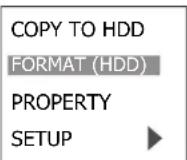
6 When formatting ends, use the cursor buttons to select COPY TO HDD and press the SET button.
- The data is copied to the hard disk in card units.

7 Use the cursor buttons to select a card slot and press the SET button.
- Then use the cursor buttons to select YES and press the SET button to start copying.
- Up to 15 copy operations can be made to one hard disk.

8 Turn the POWER switch off when copying completes.
To check data copied to hard disk
After completing step 4, use the cursor buttons to select PROPERTY and press the SET button to view hard disk data.
- To view details, use the cursor buttons to select an item and press the SET button.
To verify data copied to a hard disk
After completing step 4, use the cursor buttons to select YES for VERIFY in SETUP.
- Data copied from a P2 card will not be affected even if processing should be interrupted during verification.
- Data cannot be copied from the hard disk to a P2 card.
- Use hard disks under the following conditions.
- Use a separate power supply (not the 1394 bus) to power the hard disk since this unit cannot supply power.
- Format the hard disk for this unit.
- Operate hard disks within its operating specifications (temperature, etc.).
- Do not use hard disks in locations that are unstable or exposed to vibration.
- Some hard disks may not operate normally.
- During formatting and copying, do not disconnect cables, do not remove a P2 card that is involved in any of these activities and do not power off this unit and the hard disk. Any of these operations will require turning once off the camera and the hard disk, and then turning them on again.
- If you first set PC MODE to 1394HOST before connecting a hard disk (1394.a SBP2 compliant), normal operation is not guaranteed. Turn the power off and exit the 1394HOST mode.
- A hard disk is a precision instrument whose read and write functions may fail in some operating environments. Please note that Panasonic accepts no liability whatsoever for data loss or other losses either direct or indirect arising from hard disk damage or other defects.
- When the hard disk used to copy data from this unit is replaced with another device (PC, etc.), the data may no longer work in this unit and the hard disk data may have become corrupted.
- It is recommended that you repair bad clips on a P2 card before copying them.
- Use a stable power supply to ensure that copying, formatting and other operations are not interrupted.
Warnings
• HDD CAPACITY FULL!
There is not enough space left on the hard disk.
• TOO MANY PARTITIONS!
There are too many partitions.
• HDD DISCONNECTED!
The hard disk is disconnected.
• CANNOT INITIALIZE!
The hard disk cannot be initialized.
• TOO MANY TARGETS!
There are too may 1394 connections.
• CANNOT ACCESS TARGET!
The connected device cannot be accessed.
• CANNOT ACCESS CARD!
The card cannot be accessed.
• MISMATCH COMPONENT!
There is a mismatch with the connected device.
- UNKNOWN DEVICE CONNECTED!
A device other than a hard disk is connected.
• P2 CARD IS UNFORMATTED!
The P2 card has not been formatted.
• CARD IS EMPTY! CANNOT COPY!
There is no data on the P2 card to copy.
• VERIFICATION FAILED!
Verification turned up a mismatch.
• TURN POWER OFF!
Turn off the power.
• CANNOT RECOGNIZE HDD!
Hard disk recognition failed.
DVCPRO/DV Connection via IEEE1394 Connector
Recording DVCPRO/DV signals input to 1394 connector
1 Connect a 1394 cable.
For details, see [Precautions in 1394 Connections] (page 136).
- Make sure that the signal format of the camera and the connected device is the same.
2 To input via the IEEE1394 interface, enter MCR mode and turn off thumbnails.
- Input signals that have the same format as the setting menu MCR FORMAT and 480i (576i) MCR MODE to the IEEE1394 interface. A signal in a different format will not be correctly recorded on a P2 card. Video and audio recording and EE type video and audio of signal inputs other than 1x speed playback signals may not work.
For details, see [Errors] (page 72).
- Audio signal inputs are input signals from the 1394 connector.
- 32 kHz/4CH (12 bit) audio signals input via the IEEE1394 interface are recorded as 48 kHz/4CH (16 bit) on a P2 card.
- It is not possible to use the GENLOCK IN connector to synchronize to an external reference signal.
- Signals output from the VIDEO OUT or AUDIO OUT connectors differ from actual input signals. Use such signals for monitoring.
• The following functions do not operate.
• Pre-recording function
- Loop recording function
- Interval recording and one shot recording function
- Inputs via the 1394 interface are not available when 720P/24PN, 30PN or 25PN are selected in the setting menu MCR FORMAT.
Time Code and User Bits
- When input from the IEEE1394 interface is selected, the time code or user bits input to the TC IN connector cannot be recorded on a P2 card.
- When input from the IEEE1394 interface is selected, time code output from the TC OUT connector is not synchronized to the video signal output from the VIDEO OUT connector.
Subcode area time codes and user bits
- When input from the IEEE1394 interface is selected, or the TCG switch is set to F-RUN and the menu option F-RUN TC SLAVE in the RECORDING SETUP screen is set to 1394, the time code of the subcode area input from the 1394 connector can be recorded on a P2 card.
- To record user bits input form the 1394 connector on a P2 card, set the setting menu 1394 UB REGEN in the RECORDING SETUP screen to ON.
VAUX area time codes and user bits
When input from the IEEE1394 interface is selected, time code and user bits of the VAUX area input from the 1394 connector is recorded on a P2 card regardless of camera menu settings and switch positions.
Recording UMID (Unique Material Identifier) data
When input from the IEEE1394 interface is selected, UMID data input via the 1394 connector is recorded on a P2 card. When no UMID data is available, the camera generates and records such data. UMID data is not recorded when the camera is operating in the DV mode.
Control of external devices through 1394 connection
Using the 1394 interface to connect an external device for backup recording allows the operator to control start and stop operation of backup recording from the camera.
1 Connect a 1394 cable (DV cable).
For details, see [Precautions in 1394
Connections] (page 136).
- Set 1394 CONTROL in the setting menu OTHER FUNCTIONS screen to BOTH.
2 Use the setting menu 1394 CMD SEL (OTHER FUNCTIONS) to select the command for terminating recording that external devices receive.
For details on menu operation, refer to [Using the menus] (page 116).
- When the camera is set to REC RUN to perform backup recording on a connected external device, the advance of time code from the 1394 connector will stop when all P2 cards have been fully recorded regardless of whether backup recording continues.
- It may not be possible for an external device to back up recording when quick transitions are made between recording and stopping.
Precautions in 1394 Connections
- The camera does not supply power via the cable.
- Observe the following in connections using a 1394 cable.
- Connect this unit to only one other device.
- Do not expose the 1394 connector to excessive force when connecting a 1394 cable to avoid damaging the connector.
- If an error (1394 INITIAL ERROR) should occur when making a connection, reinsert the 1394 cable or turn the camera off and then turn it back on again.
- Make sure that the camera and all connected devices are connected to ground (or connected to a common ground). If the equipment cannot be connected to ground, turn off all connected devices before connecting or disconnecting an IEEE 1394 cable.
- When connecting the unit to a device with a 4-pin connector, connect the cable to the 6-pin connector on the camera first.
- Be sure to properly connect the 1394 cable to a personal computer with a 6-pin connector. Note that inserting the plug the wrong way round may damage the connector.
6-pin type

- AV signals may be disrupted when connected devices are turned on and off or when the interface cable is connected or disconnected.
- It may take the system a few seconds to stabilize after switching input signals or changing modes. Start recording after the system has stabilized.
- The AUDIO LEVEL control does not work in recordings that involve IEEE1394 interface input or output signals.
-
Observe the following precautions when controlling a P2 memory card camera-recorder using PC application software (editing software).
-
Recording cannot be inserted to a portion within a clip. It can only be appended to the end of the newest clip.
-
Do not open the thumbnail screen during application software operation as this may prevent normal software operation.
-
Unprocessed video and audio signals are output via the IEEE 1394 interface during special playback. When monitored on another device, these video and audio signals may sound different than when played back on this unit.
- CH1 and CH2 audio channel signals for the DV or DVCPRO (25M) format are output via the IEEE1394 interface.
Inspections Before Shooting
Make sure you check that the system is operating normally before embarking on a shoot. We recommend using a colour video monitor to check the image.
Preparing for Inspections
1 Mount a charged battery pack.
2 Turn the POWER switch to ON to check the battery remaining level in the viewfinder.
- When battery capacity is low, replace it with a fully charged battery.
| TEXTMEMO | |
| 23:59:59 | |
| T | 13.5V |
| 99 | |
3 Insert a P2 card into the card slot and close the slide cover.
- Confirm that the P2 card access LED for the inserted card slot lights up in orange. If P2 cards are inserted into multiple card slots, only the P2 card access LED for the first-inserted (first-accessed) P2 card lights up in orange. Then, the other P2 card access LEDs light up in green when P2 cards are inserted.
- If the access LED for the P2 card slot in which a P2 card is inserted keeps blinking in green, or if there is no display, recording is not possible on that particular P2 card.

natural_image
Technical line drawing of a device rear panel with a close-up inset showing a numbered control panel (no text or symbols present)Inspecting the Camera Unit
1 Set the zoom to electric zoom mode and check the zoom operation.
- Check that the image changes to telephoto and wide angle.
2 Set the zoom to manual zoom mode and check the zoom operation.
- Turn the manual zoom lever to check that the image changes to telephoto and wide angle.
3 Set the iris to automatic adjustment mode and aim the lens at objects with different degrees of brightness, to check that the automatic iris adjustment operates normally.
4 Set the iris to manual adjustment mode and turn the iris ring, to check the manual iris adjustment.
5 While holding down the instant iris automatic adjustment button, aim the lens at objects with different degrees of brightness, to check that the instant iris automatic adjustment operates properly.
6 Return the iris to automatic adjustment mode and change the GAIN switch setting to L, M, and H, to check the following items:
- The iris is adjusted for objects with the same brightness according to the switch setting.
- The gain value displayed on the viewfinder screen changes according to the switch setting.
7 When a lens with an extender is mounted, set the extender to the operating position to check that the extender operates properly.
Inspecting the Memory Recording Functions
Make sure you successively carry out the inspections from [Inspecting the P2 Card Recording] (page 138) to [Inspecting the Earphone and Speaker] (page 139).
Inspecting the P2 Card Recording
1 Check on the display inside the viewfinder that the remaining P2 card recording capacity is sufficient.
Please refer to [P2 Card Status Display] (page 113) for information about P2 card remaining recording capacity.
2 Set the TCG switch to [R-RUN].
3 Set the COUNTER button to TC.
4 Press the camera's REC START/STOP button to check the following items:
- The P2 access LED blinks in orange.
- The REC lamp inside the viewfinder lights up.
- System warnings do not appear inside the viewfinder.
5 Press the camera's REC START/STOP button again.
- This step confirms that the P2 access LED is on and showing orange, and the REC lamp in the viewfinder is turned off.
6 Using the REC START/STOP button on the handle, repeat Steps 4 to 5 to check the same operation.
- Check the VTR button on the lens in the same way.
7 Engage the MCR mode and select the recorded clip from the thumbnail to play it back.
- Check that recording and playback operate properly.
8 Use the USER button to which the SLOT SEL function has been assigned to select P2 cards for recording when more than one P2 card is inserted in the card slots.
- Repeat the operations in Steps 4 to 5 and 7 to check that recording and playback operate properly.
Inspecting the Audio Level Automatic Adjustment
1 Set the AUDIO SELECT CH1 and CH2 switches to [AUTO].
2 Set the AUDIO IN switch to [FRONT].
3 Aim the microphone connected to the MIC IN jack at an appropriate sound source. Then, check that the level displays for both CH1 and CH2 change according to the sound level.
Inspecting the Audio Level Manual Adjustment
1 Set the AUDIO IN switch to [FRONT].
2 Set the AUDIO SELECT CH1 and CH2 switches to [MAN].
3 Turn the AUDIO LEVEL CH1 and CH2 controls.
- Check that the level display increases when the controls are turned to the right.
4 Set the AUTO LEVEL CH3 and AUTO LEVEL CH4 in the setting menu AUDIO SETUP screen to OFF.
For details on menu operation, refer to [Using the menus] (page 116).
5 Set the MONITOR SELECT switch to CH3/CH4 and turn the AUDIO LEVEL CH3/CH4 controls clockwise to check that the level indication increases.
Inspecting the Earphone and Speaker
1 Turn the MONITOR control to check that the speaker volume changes.
2 Connect an earphone to the PHONES jack.
- Check that the speaker is turned off and the microphone sound can be heard from the earphone.
3 Turn the MONITOR control to check that the earphone volume changes.
Inspection for Using an External Microphone
1 Connect an external microphone to the REAR 1 and REAR 2 connectors.
2 Set the AUDIO IN switch to [REAR].
3 Set the LINE/MIC/+48V selector switches on the rear panel to [MIC] or [+48V], depending on the power supply type of the external microphone.
- MIC: For a microphone with internal power supply.
- +48V: For a microphone with external power supply.
4 Aim the microphone at the sound source and check that the sound level indication in the LCD or viewfinder varies with changes in sound intensity.
- The channels can also be checked separately by connecting a single microphone to each channel.
Inspection of the clock, time code, and user bits
1 Set the user bits as required.
Please refer to [Setting the User Bits] (page 60) for the setting procedures.
2 Set the time code.
Please refer to [Setting the Time Code] (page 62) for the setting procedures.
3 Set the TCG switch to [R-RUN].
- Press the COUNTER button to display the time code on the LCD monitor or in the viewfinder.
4 Press the REC START/STOP button.
- Check that the counter display number changes as recording progresses.
5 Press the REC START/STOP button again.
- Check that recording stops and the counter display number stops changing.
6 Set the TCG switch to [F-RUN].
- Check that the counter display number changes regardless of recording status.
7 Hold down the DISP/MODE CHK button to check the date and time on the LCD monitor or in the viewfinder.
- Adjust the date and time setting if the DATE, TIME and time zone is not correctly displayed. For details, see [Setting Date and Time of Internal Clock] (page 28).
Maintenance
Cleaning Inside the Viewfinder
- Do not use thinner or other solvents to remove dirt from the viewfinder.
- Wipe the lens with a commercially available lens cleaner.
- DO NOT wipe the mirror. If dirt or rubbish is sticking on the mirror, remove it with a commercially available air blower.
Eyepiece Care
When the CRT screen and the mirror become dusty, open the eyepiece to clean it.
The mirror is provided with a special coating. Use a blower or similar tool to remove dust from the mirror. Using tissue paper will cause dust particles to scrape against and damage the mirror surface. Use a commercially available hair-planted cloth (such as a lens cleaner) to remove more stubborn dirt.

Lock button
Opening the eyepiece
Press the lock button.
Closing the eyepiece
Press the eyepiece until the lock button clicks into place to close the eyepiece.
When outdoors, never carry or set up the camera with the eyepiece facing up to prevent sunlight, which could damage the internal parts of the eyepiece.
Phenomenon Inherent to CCD Cameras
Smears
- Smears may appear when shooting an object with very high brightness.
- This phenomenon may appear more frequently as the electronic shutter speed increases.
Charging the internal battery
The internal battery preserves the date and time settings. The appearance of ☑ in the viewfinder or LCD monitor indicates that the internal battery is exhausted.
Follow the steps below to recharge the battery. Set the date and time when the battery has been fully charged.
1 Connect the camera to an external power source.
- Leave the POWER switch on the camera off.
2 Leave the camera for about 4 hours.
- This is the time it takes to fully charge the internal battery.
- Check the time code and setting menus after completing battery charging.
Replace the internal battery if 📄 appears after charging. Consult your distributor.
Warning System
Warning Description Tables
If a problem is detected immediately after the power is turned on, or during operation, this will be indicated by the WARNING lamp, lamps inside the viewfinder and a warning tone.
| Priority | Warning type | LCD or viewfinder indication | Viewfinder LED (except tally) | Tally lamp | Warning lamp | Alarm tone *6 | Warning description and recording/ playback operation | Countermeasures |
| 1 | System error | SYSTEM ERROR Cause indication *1 Red blinking | No | Blinks 4 times per second | Blinks 4 times per second | Continuous tone | P2 microprocessor or control failure. Operation stops. | Check the cause indication *1 and consult your distributor. |
| 2 | Incorrect P2 card removal | TURN POWER OFF Blinks red | No | Blinks 4 times per second | Blinks 4 times per second | Continuous tone | A P2 card was removed during access and card data was corrupted. All four access LEDs blink orange (4 Hz) | Turn off the power. Repair the P2 card if the clips on the card are corrupted. |
| 3 | The battery is exhausted | LOW BATTERY Red blinking, and the battery level bar blinks with the empty status. (This indication appears also when MENU indications have been turned OFF.) | No | Blinks 1 time per second | Lights | Continuous tone | The battery is exhausted. Recording and playback stop. The camera stops automatically when the voltage drops. | Replace the battery. |
| 4 | P2 card fully recorded | P2 FULL Blinks red (appears only for 3 seconds in MCR mode.) | When SAVE LED is set to P2CARD, the SAVE LED blinks 4 times per second. | Blinks 4 times per second after completion of recording. | Lights after completing recording | Continuous tone after completing recording | No more space on P2 cards left for recording. Stop recording. *3 | Delete clips that are no longer needed or insert a new card. |
| 5 | Recording error | REC WARNING Cause indication *2 Blinks red | No | Blinks 4 times per second | Blinks 4 times per second | Intermittent tone 4 times per second | A recording error has occurred. Stop recording. *4 | Turn the power off and then back on again and check recording and playback. Replace any P2 card that does not enable normal recording. |
| 6 | 1394 connection errors | 1394INTIAL ERROR Blinks red | No | Blinks 4 times per second during recording. | Blinks 4 times per second during recording. | No | Incorrect 1394 connection or signal input/output error. | Check camera and external device connections and reconnect as necessary. Then turn the power off and back on again. |
| 7 | PC mode 1394 HOST connection error | No No | Blinks 4 times per second | Blinks 4 times per second | No | The 1394 cable has become disconnected or multiple devices are connected. (Normal PC mode operation is possible.) | Connect a hard disk drive according to supplied operating instructions. | |
| Priority | Warning type | LCD or viewfinder indication | Viewfinder LED (except tally) | Tally lamp | Warning lamp | Alarm tone *5 | Warning description and recording/ playback operation | Countermeasures |
| 8 | Battery nearly empty | The last bar in the battery level indication blinks (This indication appears also when MENU indications have been turned OFF.) | The BATT LED blinks (during recording, the BATT LED and the tally LED blink alternately; during pause, both LEDs blink.) | Blinks 1 time per second | Blinks 1 time per second | No | The battery is near depletion. Operation continues. *5 | Replace the battery as necessary. |
| 9 | P2 card nearly fully recorded | The P2CARD level indicator blinks. | When SAVE LED is set to P2CARD, the SAVE LED blinks 1 time per second. | Blinks 1 time per second during recording. | Blinks 1 time per second during recording. | No | Less than 2 minutes is left on the P2 cards (level indicator shows 1 minute or less). This warning appears only during recording. | Replace or insert additional P2 cards. |
*1 P2 SYSTEM ERROR cause indication
- P2 MICON ERROR: The P2 microprocessor does not respond
- P2 CONTROL ERROR: A P2 recording error has occurred
• REC RAM OVERFLOW: Overflow of recording RAM
*2 REC WARNING causes
- CARD ERROR*: P2CARD error (* indicates the number of the slot of the card with the error)
• ERROR: Other recording errors
*3 In a transition from thumbnail display to recording, a further transition is made to CAMERA mode where a warning is output.
Perform either of the following procedures to cancel this warning.
- Press a playback control button.
- Press the MODE (CAMERA/MCR/PC) button.
- Remove the P2 card and insert another card.
* Perform either of the following procedures to cancel this warning.
- Press the REC START/STOP button.
- Press a playback control button.
- Press the MODE (CAMERA/MCR/PC) button.
- Remove all cards.
*5 When NEAR END CANCEL is set to ON, you can press the DISP/MODE CHK button to cancel the alarm.
*6 When the alarm sounds, audio is not output to the camera speakers or headphones. The DISP/MODE CHK button cancels only the alarm tone when pressed during an alarm.
Updating Camera Drivers
- For the latest information on software drivers, visit the P2 Support Desk at the following Web sites. https://eww.pavc.panasonic.co.jp/pro-av/
- Before updating the camera driver, check camera driver version in the PROPERTY → SYSTEM INFO in the thumbnail menu. Then access the site listed above to download a driver if necessary.
- Place the downloaded file on an SD memory card and load the driver into the camera. For detailed information on the update procedure, visit the above site.
- The camera driver may not install properly if the power supply is not constant during installation. Be sure to provide a steady power supply throughout installation by using an external DC power supply, for example.
- The camera uses only SD memory cards that comply with the SD specifications.
- Be sure to format SD memory cards in this camera. To format an SD card on a PC, use the following software that can be downloaded from the site listed above.
Chapter10 Specifications
Dimensions and specifications
Dimensions

Specifications
General
| Power supply: DC12 V (11 V to 17 V) | |
| Power consumption: | 23 W (When 1.5 inch CRT of viewfinder and 3.5 inch LCD monitor of main unit are ON)19 W (without viewfinder, and when LCD monitor is OFF) |

indicates safety information.
| Ambient operating temperature/ humidity: | 0 °C to 40 °C (32 °F to 104 °F)/10% to 85% (no condensation) |
| Storage temperature: -20 | °C to +60 °C (-4 °F to 140 °F) |
| Weight: Approximately 3.8 kg (8.38 lb) (main unit only, excluding the viewfinder mount) | |
| Approximately 4.5 kg (9.92 lb) (including 1.5 inch CRT of viewfinder) | |
| Dimensions (W × H × D): 140 mm × 261 mm × 318 mm (5-5/8 inches × 10-3/8 inches × 12-5/8 inches)(camera excluding prominent parts) | |
Camera Unit
| Pickup devices: CCD image sensor × 3 (2/3-inch, interline transfer, progressive-capable) | |
| Lens mount: 2/3-inch bayonet type | |
| Color separation optical system: Prism system | |
| ND filter: 4 positions (CLEAR, 1/4, 1/16, 1/64) | |
| Gain settings: • 60i/60P/50i/50P mode: 0/+3/+6/+9/+12/+18 dB• In slow shutter mode: gain fixed at 0 dB• 30P/24P/25P mode: 0/+3/+6/+9/+12 dB• In slow shutter mode: gain fixed at 0 dB | |
| Shutter speed (preset): • 60i/60P mode: 1/60 (OFF), 1/100, 1/120, 1/250, 1/500, 1/1000, 1/2000 sec.• 30P mode: 1/30 (OFF), 1/50, 1/60, 1/120, 1/250, 1/500, 1/1000 sec.• 24P mode: 1/24 (OFF), 1/50, 1/60, 1/120, 1/250, 1/500, 1/1000 sec.• 50i/50P mode: 1/50 (OFF), 1/60, 1/120, 1/250, 1/500, 1/1000, 1/2000 sec.• 25P mode: 1/25 (OFF), 1/50, 1/60, 1/120, 1/250, 1/500, 1/1000 sec. | |
| Shutter speed (Synchro scan): | • 60i/60P mode: 1/60.0 to 1/249.8• 30P mode: 1/30.0 to 1/249.8• 24P mode: 1/24.0 to 1/249.8• 50i/50P mode: 1/50.0 to 1/248.9• 25P mode: 1/25.0 to 1/248.9 |
| Shutter speed (slow): | • 60i/60P mode: 1/15, 1/30• 30P mode: 1/15• 24P mode: 1/12 (720P only)• 50i/50P mode: 1/12, 1/25• 25P mode: 1/12 |
| Shutter opening angle: | • 10 degrees to 360 degrees in 0.5-degree increments (when OPERATION TYPE in the SCENE FILE screen is set to FILM CAM). |
| Frame rates: | • 59.94Hz mode: variable 12/18/20/22/24/26/30/32/36/48/60 fps (frames per second)• 50 Hz mode: variable 12/18/20/23/25/27/30/32/37/48/50 fps (frames per second) |
| Sensitivity: | F10 (Typ, 2000 lx) |
Memory Card Recorder Unit
| Recording format: DVCPRO HD / DVCPRO50 / DVCPRO/DV selectable |
| Recording audio signal: • PCM digital recording, 48 kHz/16-bits• 4 CH (DVCPRO HD/DVCPRO50), 2 CH/4 CH selectable (DVCPRO/DV) |
| Recording/playback time*: • Approx. 8 minutes (When recorded in DVCPRO HD format using one AJ-P2C008HG card with audio signals recorded on 4 channels)• Approx. 16 minutes (When recorded in DVCPRO HD format using one AJ-P2C016RG card with audio signals recorded on 4 channels) |
| Recording media: P2 Card (4GB, 8GB, 16GB are available) × 4 slots |
| Recording file: MXF file (FAT32 file system) |
| SD memory card slot: • Complies with SD format (MMC cannot be used)• 1 slot (for reading and writing camera setup data) |
* The recording time represents one shot continuously recorded on a P2 card. The recording time may be shorter depending on the number of shots recorded.
■HD video system
| Sampling frequency: Y: 74.25 MHz, PB/PR: 37.125 MHz |
| Quantizing: 8 bits |
| Video compression system: DCT + variable-length code |
| Video compression rate: 1/6.7 |
| Video recording bit rate: 100 Mbps |
■Audio system
| Sampling frequency: 48 kHz | |
| Quantizing: 16 bits/4 CH | |
| Head room: | 20 dB/18 dB (selectable) |
Video Input/Output
| GEN LOCK IN: | BNC × 1, 1.0 V p-p, 75 |
| COMPONENT OUT: | D4 terminal (component), Y: 1.0 V p-p, 75 , PB/PR: 0.7 V p-p, 75 |
| VIDEO OUT: | BNC × 1, 1.0 V p-p, 75 |
| SDI OUT: | • BNC × 1, 0.8 V p-p, 75 • HD: compliant with SMPTE 292M/296M/299M• SD: compliant with SMPTE 259M-C/272M-A/ITU-R.BT656-4 |
Audio Input/Output
| MIC IN: | • XLR × 2 (FRONT 1, FRONT 2)• high impedance• + 48 V (available)• MIC: -40 dBu/-50 dBu/-60 dBu (selectable on menu) |
| AUDIO IN: | • XLR × 2 (REAR 1, REAR 2)• high impedance• LINE/MIC / + 48 V (selectable)• LINE: 0 dB• MIC: -50 dBu/-60 dBu (selectable on menu) |
| AUDIO OUT: | Pin jack × 2 (CH 1, CH 2), Output: 316 mV, 600 Ω |
| Headphone: | ø3.5 mm stereo mini jack × 1 |
| Internal speaker: | 28 mm diameter × 1 |
Other Input/Output
| TC IN: | BNC × 1, 0.5 V p-p to 8 V p-p, 10 kΩ |
| TC OUT: BNC × 1, low impedance, 2.0 V p-p ± 0.5 V p-p | |
| IEEE1394: 6 pins, digital input/output (compliant with IEEE 1394) | |
| DC IN: XLR × 1, 4 pins, DC 12 V (11.0 V to 17.0 V) | |
| DC OUT: 4 pins, DC 12 V (11.0 V to 17.0 V), max. 1.5 A | |
| REMOTE: 10 pins | |
| LENS: 12 pins | |
| EVF: 20 pins | |
| USB2.0 (DEVICE): Type-B, 4 pins (compliant with USB ver. 2.0) | |
LCD Monitor
| LCD monitor: 3.5-inch LCD color monitor, 210,000 pixels (4:3) |
Accessories
| Accessories: • 1.5-inch viewfinder (4:3 CRT, NTSC/PAL switchable) |
| • Shoulder strap |
| • Ferrite core (2) |
| • Front Audio Level control knob (page 101) |
| • Control knob mounting screw |
| • Component video cable |
| • PIN-BNC conversion plugs (3) |
| • CD-ROM |
| • Operating Instructions |
Connector signal description
| DC IN | |
| 1 GND | |
| 2 | NC |
| 3 | NC |
| 4 +12V | |
Panasonic Part No. K1AA104H0038
Manufacturer Part No. HA16RX-4P (SW1)
(Hirose Electric Co.)

Be sure to use correct polarity when using external power supplies.
| FRONT MIC IN | |
| 1 GND | |
| 2 AUDIO IN (H) | |
| 3 AUDIO IN (C) | |
Panasonic Part No. K1AB103B0013
Manufacturer Part No. NC3FBH2 (NEUTRIK)

| AUDIO IN | |
| 1 GND | |
| 2 AUDIO IN (H) | |
| 3 AUDIO IN (C) | |
Panasonic Part No. K1AB103A0007
Manufacturer Part No. HA16PRM-3SG
(Hirose Electric Co.)

| REMOTE | |
| 1 CAM DATA (H) | |
| 2 CAM DATA (C) | |
| 3 CAM CONT (H) | |
| 4 CAM CONT (C) | |
| 5 R/C ON | |
| 6 R/C VIDEO OUT | |
| 7 R/C VIDEO GND | |
| 8 NC | |
| 9 UNREG 12V (max. 0.6 A) | |
| 10 GND | |
Panasonic Part No. K1AY110JA001
Manufacturer Part No. HR10A-7R-6SC(71)
(Hirose Electric Co.)
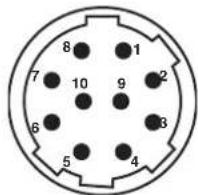
| DC OUT | |
| 1 GND | |
| 2 | NC |
| 3 | NC |
| 4 +12V OUT (max. 1.5 A) | |
Panasonic Part No. K1AY104J0001
Manufacturer Part No. HR10A-7R-4SC(73)
(Hirose Electric Co.)
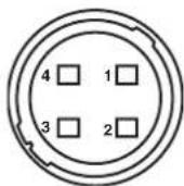
| LENS |
| 1 RET-SW |
| 2 REC-START/STOP |
| 3 GND (ground) |
| 4 IRIS-AUTO |
| 5 IRIS-CONT |
| 6 UNREG +12V (max. 0.4 A) |
| 7 IRIS-POSI |
| 8 IRIS-G-MAX |
| 9 EXT-POSI |
| 10 ZOOM-POSI |
| 11 FOCUS-POSI |
| 12 SPARE |
Manufacturer Part No. HR10A-10R-12SC(71)
(Hirose Electric Co.)
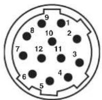
| VF | |
| 1 NOREG +12V | |
| 2 | 11 to 17 V approx. 0.2 A for the supplied viewfinder (max. 0.3 A) |
| 3 | NC |
| 4 B-Y GND | |
| 5 R-Y GND | |
| 6 VF VIDEO | |
| 7 VIDEO GND | |
| 8 VF CLK | |
| 9 VF WR | |
| 10 VF DATA | |
| 11 UNREG GND | |
| 12 ZEBRA SW | |
| 13 NC | |
| 14 NC | |
| 15 NC | |
| 16 NC | |
| 17 NC | |
| 18 NC | |
| 19 NC | |
| 20 Chassis ground | |
Panasonic Part No. K1AB102H0001
Manufacturer Part No. HR12-14RA-20SC
(Hirose Electric Co.)

MEMO
Information on Disposal for Users of Waste Electrical & Electronic Equipment (private households)

This symbol on the products and/or accompanying documents means that used electrical and electronic products should not be mixed with general household waste.
For proper treatment, recovery and recycling, please take these products to designated collection points, where they will be accepted on a free of charge basis. Alternatively, in some countries you may be able to return your products to your local retailer upon the purchase of an equivalent new product.
Disposing of this product correctly will help to save valuable resources and prevent any potential negative effects on human health and the environment which could otherwise arise from inappropriate waste handling. Please contact your local authority for further details of your nearest designated collection point.
Penalties may be applicable for incorrect disposal of this waste, in accordance with national legislation.
For business users in the European Union
If you wish to discard electrical and electronic equipment, please contact your dealer or supplier for further information.
Information on Disposal in other Countries outside the European Union
This symbol is only valid in the European Union.
If you wish to discard this product, please contact your local authorities or dealer and ask for the correct method of disposal.
Panasonic®
Panasonic Broadcast & Television Systems Company
Unit Company of Panasonic Corporation of North America
Executive Office:
One Panasonic Way 4E-7, Secaucus, NJ 07094 (201) 348-7000
EASTERN ZONE:
One Panasonic Way 4E-7, Secaucus, NJ 07094 (201) 348-7196
Southeast Region: (201) 348-7162
WESTERN ZONE:
3330 Cahuenga Blvd W., Los Angeles, CA 90068 (323) 436-3500
Government Marketing Department:
One Panasonic Way 2E-10, Secaucus, NJ 07094 (201) 348-7587
Broadcast PARTS INFORMATION & ORDERING:
9:00 a.m. - 5:00 p.m. (EST) (800) 334-4881/24 Hr. Fax (800) 334-4880
Emergency after hour parts orders (800) 334-4881
TECHNICAL SUPPORT:
Emergency 24 Hour Service (800) 222-0741
Panasonic Canada Inc.
5770 Ambler Drive, Mississauga, Ontario L4W 2T3 (905) 624-5010
Panasonic de Mexico S.A. de C.V.
Av angel Urraza Num. 1209 Col. de Valle 03100 Mexico, D.F. (52) 1 951 2127
Panasonic Puerto Rico Inc.
San Gabriel Industrial Park, 65th Infantry Ave., Km. 9.5, Carolina, Puerto Rico 00630 (787) 750-4300
Professional & Broadcast IT Systems Business Unit Europe
Panasonic AVC Systems Europe a Division of Panasonic Marketing Europe GmbH
Hagenauer Str. 43, 65203 Wiesbaden-Biebrich Deutschland Tel: 49-611-235-481
- Operating Instructions
- Memory Card Camera-Recorder
- Read this first!
- CAUTION
- WARNING:
- CAUTIONS:
- CAUTION:
- FCC Note:
- Attention/Attentie
- ENGLISH
- NETHERLANDS
- TO REMOVE BATTERY
- Precautions for Use
- Caution regarding laser beams
- PLEASE NOTE:
- Disposing and transferring ownership of memory card devices
- Information on software for this product
- Trademarks
- Contents
- Chapter 1 Introduction
- Chapter 2 Parts and their Functions
- Chapter 3 Recording and Playback
- Chapter 4 Adjustments and Settings for Recording
- Chapter 5 Preparation
- Chapter 6 Manipulating Clips with Thumbnails
- Chapter 7 Menu Operations
- Chapter 8 Connecting to External Devices
- Chapter 9 Maintenance and Inspections
- Chapter 10 Specifications
- Camera Unit Features
- ■2/3-inch interchangeable lens system
- ■Progressive 3CCD
- ■14-bit digital circuit
- ■Multiple HD/SD formats
- ■ Variable frame rate makes speed effects possible (when 720P format is selected)
- ■Native mode/Over 60P (50P) mode selectable
- ■1080/480 24P advance mode
- ■Eight gamma curves, including cine-like gamma
- ■Slow, synchro and high speed shutter
- ■Scene file dial
- ■Shooting assist functions
- ■Chromatic aberration compensation (CAC)
- ■Remote control support
- Recording and Playback Features
- ■A variety of interfaces
- ■P2 cards for high capacity, high speed and high reliability
- ■Immediate startup and reliable data protection
- ■Other features
- ■Clip thumbnail preview
- ■Shot marker and text memo
- ■SD memory card slot
- ■HD/SD SDI output and downconverter supported
- ■Fine adjustment of sound recording level
- Outline of operations
- Flow of shooting, playing and saving
- Saving and editing on external devices
- Connecting external devices via the USB connector (Page 131)
- System Configuration
- Power Supply and Accessory Mounting Section
- Audio (input) Function Section
- MIC IN (microphone input) jacks FRONT1/FRONT2 (XLR, 3-pin)
- AUDIO LEVEL CH1/CH2 (audio channel 1 & 2 recording level adjustment) controls
- AUDIO SELECT CH1/CH2 (audio channel 1 & 2 automatic/manual level adjustment selector) switch
- AUDIO LEVEL CH3/CH 4 (audio channel 3 & 4 recording level adjustment) controls
- AUDIO IN (audio input selector) switch
- REAR 1/REAR 2 (audio input channel 1 & 2) connectors (XLR, 3-pin)
- LINE/MIC/+48V (line input/mic input/mic input + 48V) selector switch
- FRONT AUDIO LEVEL (audio recording level adjustment) control
- Viewfinder connector
- Audio (output) Function Section
- MONITOR SELECT (audio channel) CH1/2 / CH3/4 selector switch
- MONITOR SELECT (audio selection) CH1/3 / ST / CH2/4 selector switch
- MONITOR/ALARM (volume) control
- Speakers
- PHONES (earphones) jack (mini jack)
- DC OUT (DC power supply) output socket
- AUDIO OUT connector
- Shooting and Recording/Playback Functions Section
- Shooting and Recording (camera unit)
- ND FILTER (filter switching) control
- USER MAIN, USER 1 and USER 2 buttons
- SHUTTER switch
- AUTO W/B (white/black) BAL switch
- GAIN selector switch
- OUTPUT/AUTO KNEE selector switch
- ■AUTO KNEE function
- WHITE BAL (white balance memory selector) switch
- DISP/MODE CHK button
- MODE button
- Shooting and Recording/Playback Function Section (recording)
- REC START/STOP button
- SAVE switch
- OUTPUT CHARACTER switch
- REW (fast-reverse) button
- F (fast forward) button
- ■ STOP button
- PLAY button
- STILL (pause) button
- REC buttons (red and white)
- P2 CARD ACCESS LED
- Slide lock button
- USB 2.0 connector
- GENLOCK IN connector
- REMOTE (remote control) connector
- VIDEO OUT (video signal output) connector
- SD memory card insertion slot
- BUSY (operation mode display) lamp
- R-SIDE P2 card access LED
- COMPONENT OUT connector (D4 connector)
- 1394 connector
- SDI OUT connector
- SCENE FILE dial
- PAGE/VAR button
- FOCUS ASSIST button
- Recording enable/disable switch
- Menu/Thumbnail Operation Section
- MENU button
- Thumbnail button
- Thumbnail menu button
- MODE button
- CURSOR and SET buttons
- PAGE/VAR button
- JOG dial button
- Time Code Section
- GENLOCK IN connector (BNC)
- TC IN connector (BNC)
- TC OUT connector (BNC)
- HOLD button
- RESET button
- COUNTER (counter display selector) button
- TCG (time code selector) switch
- CURSOR and SET buttons
- Warning and Status Display Functions
- Back tally lamp
- BACK TALLY switch
- WARNING lamp
- Rear tally lamp
- Mode LED
- LCD Monitor
- LCD monitor
- OPEN button
- Viewfinder
- Viewfinder (supplied accessory)
- ZEBRA (zebra pattern) switch
- TALLY switch
- PEAKING control
- CONTRAST control
- BRIGHT control
- Front tally lamp
- Viewfinder securing screw
- Eyepiece
- Diopter adjustment ring
- Connecting plug
- Locking button
- Microphone holder
- Chapter3
- Recording and Playback
- Setting Date and Time of Internal Clock
- OTHER FUNCTIONS
- CLOCK SET
- P2 Cards
- Inserting P2 Cards
- Close the slide-out door.
- Removing P2 Cards
- Then depress the eject button to release the P2 card.
- To Prevent Accidental Erasure of P2 Card Content
- P2 CARD ACCESS LED and status of P2 cards
- Splitting clips recorded on P2 cards
- Handling P2 Card Recording
- Basic Procedures
- Battery Set-up to P2 card Insertion
- Setting the switches before shooting and recording
- Iris
- USER MAIN/USER1/USER2
- GAIN switch
- AUTO KNEE selector switch
- TCG
- AUDIO SELECT CH 1/CH 2
- Shooting
- White/Black Balance Adjustment to Recording Completion
- Use the ND FILTER control to select a filter according to light conditions.
- ■ When the white balance is saved:
- ■ If the white balance is adjusted on the spot:
- Point the camera at your subject to adjust the focus, and zoom.
- Press the REC START/STOP button to start recording.
- To stop recording, press the REC START/STOP button.
- Normal Recording
- Variable Frame Rate (VFR) Recording
- 24PN mode:
- Native recording
- Press the REC START/STOP button.
- Standard recording
- Select the 720P/60P, 720P/30P, or 720P/24P (720P/50P, or 720P/25P at 50 Hz) recording format in the REC FORMAT item in the RECORDING SETUP screen.
- Select the appropriate scene file using the SCENE FILE dial.
- Using the OPERATION TYPE function on the SCENE FILE screen, select FILM CAM, and set the desired recording frame rate using the FRAME RATE function.
- Using variable frame rates (VFR)
- Standard speed shooting for making commercials and dramas
- Shooting at standard speed for producing commercials and TV programs
- Undercrank shooting
- Overcrank shooting
- Shooting in the 1080i/480i Progressive Mode
- ■30P mode
- ■24P mode
- Special Recording Modes
- Pre-recording (PRE REC)
- Press the REC START/STOP button.
- Interval recording (INTERVAL REC)
- One-shot recording (ONE-SHOT REC)
- Loop recording (LOOP REC)
- Check that the OPERATION TYPE item in the menu option SCENE FILE screen and REC FORMAT item in the menu option RECORDING SETUP screen are set as described below.
- Select LOOP in the REC FUNCTION item in the menu option RECORDING SETUP screen.
- Hot Swap Recording
- Recording Check Function
- Shot Marker (SHOT MARK) Recording Function
- To add shot marks
- Text Memo Recording Function
- To add text memos
- Normal and Variable Speed Playback
- ■Normal speed playback
- ■Fast-forward/fast-reverse playback
- Clip cue up
- ■Variable speed search
- ■Frame-by-frame playback
- Video and recording formats
- Multiple HD/SD formats
- Selecting recording signals in CAMERA MODE
- Selecting MCR mode recording and playback signals
- Selecting video output
- List of recording, playback and output formats
- CAMERA mode (recording)
- MCR mode (playback and recording of 1394 input)
- Adjusting the White balance and Black Balance
- Adjusting the White Balance
- The adjustment will take effect in a few seconds, and the following message will appear:
- If the subject's colour temperature is lower than 2300K or higher than 9900K the following message appears:
- When you have no time to adjust the white balance
- When the white balance has not been automatically adjusted
- Viewfinder displays related to white balance
- Adjusting the Black Balance
- The adjustment will take effect in a few seconds and the following message will appear:
- Retaining black balances
- Setting the Electronic Shutter
- Setting the Shutter Mode and Speed
- Viewfinder displays relating to the shutter
- Placing the Camera-recorder in SYNCHRO SCAN Mode
- Range of variation in each mode
- ■59.94 Hz mode
- ■50 Hz mode
- Assigning functions to USER buttons
- Selectable Functions
- Selecting Audio Input Signals and Adjusting Recording Levels
- Selecting Audio Input Signals
- Adjusting Recording Levels
- 3
- Selecting Function for the FRONT AUDIO LEVEL Control
- CH3 and CH4 Recording Levels
- Setting Time Data
- Time data overview
- Time code
- User bits
- ■Date (real time)
- Recording time codes and user bits
- Setting user bits
- - USER
- • TIME
- • DATE
- • TCG
- • FRM. RATE
- Entering the User Bits
- 4
- 5
- Retaining the user bits
- Frame rate information recorded in user bits
- ■Frame rate information
- When 1080i, 480i or 576i
- Frame rate: 24PA over 60i (2:3:3:2)
- 720P mode
- Setting the Time Code
- Use the CURSOR buttons to set the time code.
- TC PRESET
- Press the SET button to confirm the time code setting, and use the TCG switch to select a time code.
- Time code function during battery replacement
- Time code in 720P native mode
- Externally Locking the Time Code
- Connections for externally locking the time code (examples)
- To externally lock the time code
- Setting the user bits when the time code is externally locked
- To unlock the externally locked time code
- Cautions in switching the power source from battery to external power supply
- External synchronisation of the camera when the time code is externally locked
- Outputting the time code externally
- GENLOCK and time code input/output connection and setup
- Counter Setting and Display
- Viewfinder Screen Status Displays
- Lamps in the Viewfinder Screen
- TALLY/REC (recording) Lamp
- Abnormal Operating Status Warning Lamp
- BATT (battery) Lamp
- SAVE Lamp
- 50M indication lamp
- Viewfinder Status Indication Layout
- Selecting Viewfinder Display Information
- Screen displays
- Time code displays
- Warnings
- Backup unit displays
- Recording format and system frequency indication
- - Recording format
- - System frequency
- Information display
- Squeeze information
- AWB display
- Marker luminance display
- Calendar
- Recording/playback frame rate display
- Shutter speed
- Audio level meter display
- IRIS display
- Zoom position display
- Auto iris control displays
- Remaining battery charge
- Text memo and shot mark indicator
- Recommended ND filter
- ND filter display
- Gain display
- WHITE BAL switch position indication
- Center marker display
- Scene file name display
- Media remaining memory display
- Operational state display
- Media information display
- Special recording display
- Lens chromatic aberration compensation (CAC) indicator
- AWB, ABB error indication
- ■Safety zone
- Warnings
- • COPY INHIBITED
- • EXTERNAL 1394 DISCONNECT
- • INCOMPATIBLE CARD
- • DIR ENTRY NG CARD
- • RUN DOWN CARD
- - FORMAT ERR!
- • CANNOT ACCESS
- • CANNOT DELETE
- • CANNOT FORMAT
- • CANNOT REPAIR
- - CARD FULL
- • WRITE PROTECTED
- - NO CARD
- • NO FILE
- P2 card playback data indication
- Errors
- • CANNOT REC
- • CANNOT PLAY
- - SYSTEM ERROR
- • TURN POWER OFF
- - REC WARNING
- • 1394
- - LOW BATTERY:
- Camera status display
- USER buttons assignment information (at mode check)
- ! LED light indication (at mode check)
- Checking and displaying shooting status
- Setting the Marker Displays
- Adjusting and setting the LCD monitor
- Using the LCD Monitor
- Self-portrait Shooting
- Handling setup data
- Configuration of setup data files
- Setting Data Using an SD memory card
- Handling SD memory cards
- To insert an SD memory card
- To remove the SD memory card
- SD memory cards must not be used or stored in an environment where they may be
- Formatting, Writing and Reading an SD memory card
- To format an SD memory card
- To format the SD memory card, turn the JOG dial button to move the cursor to YES. Then, press the dial button.
- How to Use Scene File Data
- ■Factory setting
- Changing scene file settings
- Turn the JOG dial button to move the cursor to the option LOAD/SAVE/INT. Then, press the JOG dial button.
- Turn the JOG dial button to move the cursor to the option SAVE. Then, press the JOG dial button.
- Turn the JOG dial button to move the cursor to YES. Then, press the dial button.
- Saving scene files and other settings on SD memory cards
- To load a file
- Reloading Files From an SD Memory Card
- To title a file
- Perform steps 1 to 4.
- Use the JOG dial button to select characters, then press the JOG dial button to move to the next character.
- When all inputs are completed, press the ◀cursor button at the left edge of the characters (or press the ▶cursor button at the right edge or use the JOG dial button).
- Turn the JOG dial button to select YES and press the JOG dial button.
- Memory Card Usage
- ■Memory cards that can be used
- ■Cards that cannot be used
- Chapter5 Preparation
- Power Supply
- Using a Battery Pack
- Mounting the Battery and Setting the Battery Type
- Using an Anton/Bauer Battery Pack
- Mount an Anton/Bauer battery pack.
- Insert the battery and slide it in the direction of the arrow.
- Set the battery type.
- ■ The following Anton/Bauer batteries can be used:
- Using an NP-1 type battery pack
- Remove the battery holder.
- Mount the NP-1 type battery case on the camera-recorder.
- When using a V-mount type battery pack
- Setting the battery type
- Use of the external DC power supply
- Connect the external DC power supply to the DC IN socket on the unit.
- Mounting the Viewfinder and Adjusting its Position
- Mounting the Viewfinder
- Adjusting Viewfinder Right- Left Position
- Diopter Adjustments
- Screen Adjustments
- Removing the Viewfinder
- Mounting and Adjusting the Lens
- Mounting the Lens
- Raise the lens clamping lever and remove the mount cap.
- To mount the lens, align the indentation at the top center of the lens mount with the center mark of the lens.
- Lower the lens clamping lever to clamp the lens.
- Secure the cable through the cable clamp, and plug it into the LENS connector.
- Adjust the lens flange back.
- Adjusting the Lens Flange Back
- White Shading Compensation
- Selecting White Shading Compensation Data
- Use the JOG dial button to select DEFAULT, USER1, USER2, USER3 or OFF and press the JOG dial button.
- White Shading Adjustment
- 1
- Place the camera in the adjustment mode.
- Set the image.
- Adjust white and black balance.
- Repeat the operation in step 2-(2).
- Adjust white shading.
- If the lens is provided with an extender, turn on the extender function and perform steps 2 to 5 again.
- Setting Chromatic Aberration Compensation (CAC)
- Checking CAC Operating Status
- Checking CAC data number and CAC data during operation
- Open the setting menu LENS SETUP screen.
- Turn the JOG dial button to select CAC PROPERTY and select YES to open the CAC PROPERTY screen.
- Current CAC data number
- Data number of CAC you wish to check Turn the JOG dial to select.
- CAC data specified by 2
- Error messages
- Loading CAC File From an SD Card
- Use the JOG dial button to select CAC CARD READ. Then select YES to open the CAC CARD READ screen.
- Use the JOG dial button to select the CAC file to load. Then select YES and press the JOG dial button.
- Deleting CAC File
- Use the JOG dial button to select CAC FILE DELETE, select YES and press the JOG dial.
- Use the JOG dial to select the CAC file to be deleted. Then select YES and press the JOG dial button.
- Initializing CAC File (Returning Data to Their Factory Defaults)
- Use the JOG dial button to select CAC FILE INIT. Then select YES to display the confirmation screen.
- Select YES in the confirmation screen and press the JOG dial button.
- Preparing for Audio Input
- When Using the Front Microphone
- Open the microphone holder.
- Mount the microphone and tighten the clamping screw.
- Connect the microphone cable to the MIC IN jack on the camera.
- Set the AUDIO IN switch to [FRONT] depending on the audio channel to be recorded.
- When Using Audio Devices
- Attaching Accessories
- Mounting the Camera on a Tripod
- Removing the Camera from the Tripod Adapter
- Attaching the Shoulder Strap
- Attaching the Rain Cover
- Attaching the FRONT AUDIO LEVEL Control Knob
- Connecting the AJ-RC10G Extension Controller
- Chapter6
- Manipulating Clips with Thumbnails
- Thumbnail Operations
- Thumbnail Overview
- THUMBNAIL
- OPERATION
- PROPERTY
- META DATA
- Thumbnail Screen
- Slot number
- Thumbnails
- Thumbnail display status
- Clip numbers
- Menu display
- Recording mode/format display
- Indicators
- X (Defective clip):
- V (Voice memo):
- T (Text memo):
- E (Edit copy):
- P (Proxy):
- Duration display
- Selecting Thumbnails
- Use the cursor buttons to move the pointer (yellow frame) to the desired clip and press the SET button.
- Additional clips can be selected by repeating Step 1.
- Switching the Thumbnail Display
- Press the MODE button to enter the MCR mode.
- Press the thumbnail menu button to open the menu.
- Move the pointer to THUMBNAIL and select with the SET button.
- ■To delete a text memo
- Setting the Thumbnail Display Mode
- Clip Operations
- Playing Back Clips
- Use the cursor buttons to move the pointer over the desired clip.
- Press the PLAY button, and the clip under the pointer will be played back on the LCD monitor.
- During playback, pressing the REW button starts 4× speed reverse playback, and the FF button starts 4× speed fast playback.
- During clip playback, pressing the STILL button will temporarily stop (pause) the process.
- Pressing the STOP button during clip playback stops the playback and returns the display to the thumbnail screen.
- Shot Mark
- Use the cursor buttons to move the pointer over the clip to which you want to attach a shot mark.
- Press the USER button to which the shot mark function has been assigned.
- A shot mark will be attached to the clip thumbnail under the pointer.
- Deleting Clips
- Use the cursor buttons to move the pointer over the clip you want to delete, and press the SET button.
- Press the thumbnail menu button to select OPERATION → DELETE from the menu bar.
- A screen to confirm the delete operation appears. Use the cursor buttons and the SET button to select YES.
- Restoring Clips
- Use the cursor buttons to move the pointer over the clip you want to restore (defective clips are indicated by corrupt clip marks), and press the SET button.
- Press the thumbnail menu button to select OPERATION → REPAIR CLIP from the menu bar.
- The confirmation window appears. Use the cursor buttons and the SET button to select YES.
- Setting of Clip Meta Data
- Reading Clip Meta Data (metadata upload)
- Clip metadata content
- - NEWS:
- - MEMO\*:
- To set whether or not the uploaded metadata is recorded
- Selecting the USER CLIP NAME recording method
- Clear the uploaded metadata
- Displaying loaded metadata
- Formatting P2 and SD Memory Cards
- Formatting a P2 Card
- From the menu bar, select OPERATION → FORMAT.
- Use the CURSOR and SET buttons to select YES in the screen that confirms whether you want to format the card.
- Formatting SD memory cards
- Select OPERATION → FORMAT.
- Properties
- Clip Property
- P2 Card Status Display
- P2 Card Status Display Settings
- Contents of P2 Card Status Display Settings
- Write-protect Mark
- P2 Card Status (remaining free space)
- P2 Card Remaining Capacity/Total Capacity
- Total remaining memory capacity for all cards
- Warning card mark
- P2 Card Status (used memory capacity)
- - FORMAT ERROR:
- • NOT SUPPORTED:
- - NO CARD:
- P2 Card memory capacity/Total Capacity
- Total used memory capacity for all slots
- SD memory card Status Display
- ■Screen showing SD memory card data
- Confirmation of Metadata Upload
- Chapter7 Menu Operations
- Viewfinder and LCD Menus
- Using the menus
- When the unit is in other than playback or recording mode, press the MENU button.
- CAMERA MENU
- 1.SCENE FILE
- Use the JOG dial button (or the Up and Down cursor buttons) to highlight the function you want to change.
- Press the JOG dial button (or the SET button) to display the items.
- SW MODE
- MID GAIN
- Initializing the menu settings
- To initialize the user file (i.e. all the settings other than the scene file settings)
- To initialize the scene file
- Setup menu structure
- Camera (CAM) mode menu
- MCR mode menu
- ■ Marks used in the list
- SCENE FILE screen
- OTHER FUNCTIONS screen
- OPTION MENU screen
- Chapter8
- Connecting to External Devices
- Connecting to External Devices Using USB2.0 Port (PC mode)
- Procedures for establishing a connection with a PC
- Connect the USB cable to the USB 2.0 port.
- Open the setting menu screen, and set the menu option PC MODE to USB DEVICE.
- Press the MENU button to end menu operations.
- Press the MODE button to turn on the MCR mode LED and keep the button held down.
- Edit data on the PC.
- To exit the PC MODE, turn the POWER switch OFF.
- Connecting to External Devices Using the IEEE1394 Connector (PC mode)
- Connect the IEEE1394 cable to the 1394 connector.
- Open the setting menu screen and set the menu option PC MODE to 1394DEVICE.
- Procedures for connecting a hard disk
- To check data copied to hard disk
- To verify data copied to a hard disk
- DVCPRO/DV Connection via IEEE1394 Connector
- Recording DVCPRO/DV signals input to 1394 connector
- Connect a 1394 cable.
- To input via the IEEE1394 interface, enter MCR mode and turn off thumbnails.
- Time Code and User Bits
- Subcode area time codes and user bits
- VAUX area time codes and user bits
- Recording UMID (Unique Material Identifier) data
- Control of external devices through 1394 connection
- Connect a 1394 cable (DV cable).
- Use the setting menu 1394 CMD SEL (OTHER FUNCTIONS) to select the command for terminating recording that external devices receive.
- Precautions in 1394 Connections
- Inspections Before Shooting
- Preparing for Inspections
- Inspecting the Camera Unit
- Set the zoom to electric zoom mode and check the zoom operation.
- Set the zoom to manual zoom mode and check the zoom operation.
- Set the iris to automatic adjustment mode and aim the lens at objects with different degrees of brightness, to check that the automatic iris adjustment operates normally.
- Set the iris to manual adjustment mode and turn the iris ring, to check the manual iris adjustment.
- While holding down the instant iris automatic adjustment button, aim the lens at objects with different degrees of brightness, to check that the instant iris automatic adjustment operates properly.
- Return the iris to automatic adjustment mode and change the GAIN switch setting to L, M, and H, to check the following items:
- When a lens with an extender is mounted, set the extender to the operating position to check that the extender operates properly.
- Inspecting the Memory Recording Functions
- Inspecting the P2 Card Recording
- Check on the display inside the viewfinder that the remaining P2 card recording capacity is sufficient.
- Set the TCG switch to [R-RUN].
- Set the COUNTER button to TC.
- Press the camera's REC START/STOP button to check the following items:
- Press the camera's REC START/STOP button again.
- Using the REC START/STOP button on the handle, repeat Steps 4 to 5 to check the same operation.
- Engage the MCR mode and select the recorded clip from the thumbnail to play it back.
- Inspecting the Audio Level Automatic Adjustment
- Inspecting the Audio Level Manual Adjustment
- Inspecting the Earphone and Speaker
- Inspection for Using an External Microphone
- Inspection of the clock, time code, and user bits
- Set the user bits as required.
- Set the time code.
- Set the TCG switch to [R-RUN].
- Press the REC START/STOP button again.
- Set the TCG switch to [F-RUN].
- Hold down the DISP/MODE CHK button to check the date and time on the LCD monitor or in the viewfinder.
- Maintenance
- Cleaning Inside the Viewfinder
- Eyepiece Care
- Opening the eyepiece
- Closing the eyepiece
- Phenomenon Inherent to CCD Cameras
- Smears
- Charging the internal battery
- Warning System
- Warning Description Tables
- Updating Camera Drivers
- Chapter10 Specifications
- Dimensions and specifications
- Dimensions
- Specifications
- Connector signal description
- MEMO
- Information on Disposal for Users of Waste Electrical & Electronic Equipment (private households)
- For business users in the European Union
- Information on Disposal in other Countries outside the European Union
- Panasonic®
- Panasonic Broadcast & Television Systems Company
- Unit Company of Panasonic Corporation of North America
- Panasonic Canada Inc.
- Panasonic de Mexico S.A. de C.V.
- Panasonic Puerto Rico Inc.
- Professional & Broadcast IT Systems Business Unit Europe
- Panasonic AVC Systems Europe a Division of Panasonic Marketing Europe GmbH
Brand : PANASONIC
Model : AG-HPX500E
Category : Video camera