
XJ6 (1994) - Car JAGUAR - Free user manual and instructions
Find the device manual for free XJ6 (1994) JAGUAR in PDF.


| Product Type | Passenger Car |
| Brand | Jaguar |
| Model | XJ6 (XJ40) |
| Year | 1994 |
| Engine Displacement | 4.0 L (243 cu in) I6 |
| Power Output | 241 hp (180 kW) @ 5100 rpm |
| Transmission | 4-speed automatic (ZF 4HP22) |
| Drivetrain | Rear-wheel drive |
| Length | 4,988 mm (196.4 in) |
| Width | 1,798 mm (70.8 in) |
| Height | 1,308 mm (51.5 in) |
| Wheelbase | 2,870 mm (113.0 in) |
| Curb Weight | 1,700 kg (3,748 lb) |
| Fuel Type | Petrol (unleaded) |
| Fuel Tank Capacity | 81 L (21.4 US gal) |
| Tire Size | 205/70R15 |
| Brakes | Front and rear disc brakes, ABS |
| Safety Features | Driver airbag, ABS, seatbelt pretensioners |
| Maintenance Interval | Every 12,000 km (7,500 mi) or 12 months |
| Recommended Engine Oil | SAE 10W-40 (API SG or higher) |
| Spare Parts Availability | Widely available through specialist dealers |
Frequently Asked Questions - XJ6 (1994) JAGUAR
User questions about XJ6 (1994) JAGUAR
0 question about this device. Answer the ones you know or ask your own.
Ask a new question about this device
Download the instructions for your Car in PDF format for free! Find your manual XJ6 (1994) - JAGUAR and take your electronic device back in hand. On this page are published all the documents necessary for the use of your device. XJ6 (1994) by JAGUAR.
USER MANUAL XJ6 (1994) JAGUAR
Vehicle Service Manual
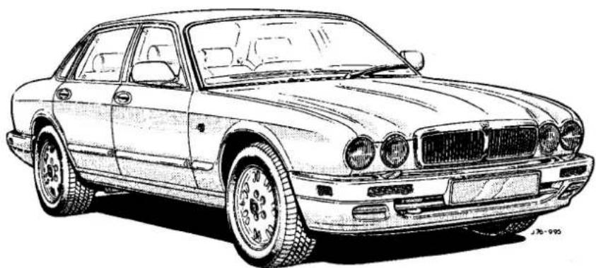
Published by Product Development & Publications
Jaguar Cars Limited
Publication Part Number - JJM 1004 12 / 50

FOREWORD
This Vehicle Service Manual (VSM) is Part of a set of service literature which covers procedures for the efficient diagnosis and rectification of problems associated with all areas of the X300 family of vehicles.
It is designed to be read in conjunction with other manuals, namely the various Unit Service Manuals (USM) (as applicable to the particular vehicle under diagnosis/ repair) and the X300 Electrical Diagnostic Manual (EDM); see list below.
It should be noted that its scope is limited to those areas that are unique to the family, e.g. Remove& Refit procedures for Body Components, Engine, Transmission etcetera, Fuel, Emissions & Engine Management systems, and so on.
Fault Diagnosis and repair procedures (together with Technical Data, Recommended Lubricants, Capacities etcetera) for major assemblies such as engines, automatic and manual transmissions, are covered in the separate Unit Service Manuals.
The UnitService Manuals are not vehicle-specific, but are designed to be read in conjunction with this VSM, and, where so equipped, with other Jaguar Vehicle Service Manuals for new models launched subsequent to the X300 family.
The X300 Electrical Diagnostic Manual is the final part of the 'set' of service documentation. This manual is family-specific, and is designed to aid the Technician to isolate electrical faults and to correct them. It covers all aspects of electrical fault diagnosis, including:
OBD II Codes and emission control system related fault diagnosis/ rectification.
Circuit Diagrams
Component (Relays, fuse boxes, control modules etcetera) Location / Harness Diagrams
Ground Locations
Connector Locations.

Service Manuals Required
The Manuals required to service the X300 family of vehicles are as follows:
X300 Vehicle Service Manual
X300 Electrical Diagnostic Manual
Unit Service Manuals:
AJ16 Engine Service Manual
V12 Engine Service Manual
ZF Automatic Transmissions Service Manual(ZF suppliestransmissions for 3.2 liter and 4.0 liter normally aspirated versions)
Powertrain Automatic Transmissions Service Manual (The Powertrain name succeeds that of Hydra-Matic.
Powertrain are suppliers of the 4L 80 E transmission as fitted to 4.0 litre supercharged and 6.0 litre versions)
Each of the X300-specific manuals is divided into Sections which adopt the same title and number where relevant, i.e. Section 5.1 of both the VSM and the EDM cover Fuel, Emission Control & Engine Management System (AJ16). An over-all contents list showing each section title and number together with its page-edge locator is given in this section and in the introduction to the EDM.
The VSM (not applicable to the EDM) also contains Appendices which cover specialized areas such as the current vehicle specification, routine maintenance schedule etc. These are carried at the rear of this Manual, and have their own contents page within this section.

INDEX
This manual carries a comprehensive index at the rear, which is designed to save the Technician time by permitting rapid location of information. The entries are set out as per the following example:
CLIMATE CONTROL SYSTEMS. Section14.
See also Electrical Diagnostic Manual
Clutch
Description: Sect. 7.7 - 10
Fault diagnosis: Sect 7.1-11
In the example the heading in upper case lettering is to a section title, and it refers to the section number, 14, and also to the EDM as electrical diagnostic information will be found in that manual's section 14.
The entry for clutchtells us that the relevant description will be found on page 10 of Section 7.1 of this manual, and that fault diagnosis procedures start on page 11.
In this case there is no reference to the EDM as electrical diagnosis does not apply to this area.
GLOSSARY OF TERMS
This Section contains a Glossary of general and emissions-related terminology (commencing on page 5).

1
SERVICE REPAIR OPERATION (SRO) NUMBERING
A master index of numbered operations has bee? compiled for universal application to all vehicles manufactured by Jaguar Cars Ltd.
Each operation described in this manual is allocated a number from the master index and crossrefers with an identical number in the Service Repair Operation Times Manual. The number consists of six digits arranged in three pairs. Each operation is described in the sequence necessary to complete the operation in the minimum time, as specified in the Manual of Repair Operation Times.
SERVICE TOOLS
Where non-standard service tools (i.e. tools which are not generally available handtools) are required to complete an operation, the number and an illustration of that tool is given in the preliminary pages of the Section concerned.
TORQUE TIGHTENINGSPECIFICATIONS
Torque tightening specifications are given in tabular form in the preliminary pages of the relevant Section.
REPAIRS AND REPLACEMENTS
When service parts are required, it is essential that only genuine Jaguar / Daimler replacements are used.
Attention is drawn to the following points concerning repairs and the fitting of replacement parts and accessories:
Safety features embodied in the vehicle may be impaired if other than genuine parts are fitted. In certain territories, legislation prohibits the fitting of parts which are not produced to the vehicle manufacturer's specification.
- Torque wrench setting figures given in this Manual must be strictly adhered to.
- Locking devices, where specified, must be fitted. If the efficiency of a locking device is impaired during removal it must be renewed.
Owners purchasing accessories while travelling abroad should ensure that the accessory and its fitted location on the vehicle conforms to mandatory requirements existing in their country of origin.
The vehicle warranty may be invalidated by the fitting of other than genuine Jaguar / Daimler parts. All Jaguar /Daimler replacements have the full backing of the factory warranty.
- Jaguar / Daimler dealers are obliged to supply only genuine service parts.
REFERENCES
References to the left or right-hand side of the vehicle are made as if viewing from the driver's seat.
SPECIFICATION
Purchasers are advised that the specification details set out in this Manual apply to a range of vehicles and not to any specific one. For the specification of a particular vehicle, purchasers should consult their dealer.
The Manufacturers reserve the right to vary their specifications, with or without notice, and at such times and in such manner as they thinkfit. Major as well as minorchanges may be involved in accordance with the Manufacturer's policy of continuous improvement.
Whilst every effort is made to ensure the accuracy of the particulars contained in this Manual, neither the Manufacturer nor the Dealer, by whom this Manual is supplied, shall in any circumstances be held liable for any inaccuracy or the consequences thereof.
COPYRIGHT
Copyright.© Jaguar Cars Ltd. 1994
All rights reserved. No part of this publication may be reproduced, stored in a retrieval system or transmitted in any form, electronic, mechanical, photocopying, recording or other means, without prior written permission of Jaguar Cars Ltd., Service Department, Browns Lane, Coventry, CV59DR, England.
Contents
| Introduction | 1 |
| Jacking, Lifting & Vehicle Recovery | 2 |
| Engine (AJ16) | 3.1 |
| Engine (V12) | 3.2 |
| Cooling System (AJ16) | 4.1 |
| Cooling System (V12) | 4.2 |
| Fuel, Emission Control & Engine Management (AJ16) | 5.1 |
| Fuel, Emission Control & Engine Management (V12) | 5.2 |
| Exhaust System (AJ16) | 6.1 |
| Exhaust System (V12) | 6.2 |
| Manual Transmission & Clutch (AJ16) | 7.1 |
| Automatic Transmission (AJ16) | 8.1 |
| Automatic Transmission (V12 & AJ16 Supercharged) | 8.2 |
| Driveshafts & Final Drive | 9 |
| Steering | 10 |
| Suspension Systems | 11 |
| Brakes | 12 |
| Body Components & Trim | 13 |
| Climate Control Systems | 14 |
| Electrical | 15 |
Contents – Appendices
| Specification | A1 |
| Routine Maintenance | A2 |
| General Fitting Instructions | A3 |
| Body Systems & Body Repair | A4 |
| Security System (Restricted Issue) | A5 |
| Index | I |


GLOSSARY OF TERMS
Introduction
This glossary of terms is intended to cover both general and emissions-related (to SAEJ 1930) terminology. It is intended to enable the user to ascertain the meaning of standardized terms and acronyms used throughout the Manual. The required term may be looked-up in the lefthand column, and subsequent columns give the standard abbreviation or acronym, definitions and previously used terms, as applicable.
As this Manual is a world-wide publication, and must comply with certain Society of Automotive Engineers Standards, it has been necessary to adopt the terminology etc. demanded by that Standard.
| Term(s) | Abbreviation (If applicable) | Definition | Previously used term(s) (or English Equivalent) |
| A | |||
| accelerator pedal | AP | throttle pedal | |
| across flats | AF | measurement across the spanner flats of a nut or bolt head | |
| adapter | adaptor | ||
| after bottom dead center | ABDC | event occurring after BDC | |
| after top dead center | ATDC | event occurring after TDC | |
| Air Cleaner | ACL | ||
| Air Conditioning | A/C | AC. aircon | |
| Air Conditioning Signal | ACS | air conditioning compressor clutch operation is signalled to the PCM which induces idle speed corrections to compensate for engine load changes | |
| Air ning Control Module | A/CCM | module controlling air conditioning, heating and ventilation | |
| airfoil | wing or similar, designed to obtain some effect from the flow of air over it | aerofoil | |
| alternating current | ac | electrical current whose flow alternates in direction, in a sinusoidal wave-form | |
| aluminum | aluminium | ||
| Ambient temperature | Temperature of the air surrounding an object | ||
| Ampere | A | SI unit of current | Amp |
| Ampere hour | Ah | I Aimpele flowing for one hour | Amp. hour |
| Anti-Lock Braking System | ABS | system, usually elec - ii II controlled (but can be mechanically) which prevents wheel lock-up under braking by sensing lack of rotation of a wheel(s) and diverting fluid pressure away from it (them). Originally Anti-Blockier System(Bosch). | |
| ABS control module | ABS CM | ||
| ABS / traction control control module | ABS / TC CM | ||
| antenna (plural, antennae or antennas) | aerial | ||
| analog | analogue | ||
| Analog Volt-Ohm meter | AVOM | ||
| atmosphares | atm | unit of pressure(1.01325 bar) | |
| automatic transmission | auto, auto gearbox | ||
| axle shaft | shaft transmitting power to the rear wheel hubs | drive shaft | |


1
GLOSSARY OF TERMS
| Term(s) | Abbreviation (if applicable) | Definition (or | Previously used term(s) English Equivalent) |
| 5 | |||
| Babbitt metal | white metal | ||
| backlight | backlight, rear screen reversing lamp | ||
| back-up lamp | |||
| balk ring | rotating component of manual transmission which prevents premature engagement of gears | baulk ring | |
| battery positive Voltage | B+ | The positive Voltage from a battery or any circuit connected directly to it. | B+, +ve, VSS |
| Barometric Absolute Pressure Sensor | BARO | sensor measuring the pressure of surrounding air at any given temperature and altitude | BARO, APS |
| base Idle | Idle rpm determined by the throttle lever being hard-set on the throttle body with the IAC solenoid disconnected | ||
| base timing | Spark advance in degrees before top dead center of the base engine without any control from the PCM | ||
| battery | Electrical storage device producing DC Voltage by means of electrochemical reaction | ||
| before bottom dead center BBDC | event occurring before BDC | ||
| before top dead center BTDC | event (usually ignition) occurring before TDC | ||
| blower BLR | Device which supplies a current of air at moderate pressure, e.g. heater or A/C blower | ||
| Body Processor Module | BPM | Control module for body electrical systems, e.g. interior lamps, windshield wash / wipe control etc.. | CCM (Central Control Module). CPU |
| British Standards | BS | standard specification issued by the British Standards Institution | |
| British Standards Automotive | BSAu | ||
| brake horsepower | bhp | effective horsepower developed by an engine or motor, as measured by a brake applied to its output shaft | |
| brake mean effective pressure | BMEP | that part of the effective pressure developed in a cylinder that would result in a cylinder output equal to thebhp of the engine | |
| brake on/off | BOO | indicates the position of the brake pedal | |
| brake rotor | brake disc | ||
| break-in, breaking-in, wearing-in | process of bedding-in the internal working surfaces of e.g. an engine by avoiding excess build-up of heat | running-in | |
| bottom dead center | BDC | lowest point of piston travel in a reciprocating engine | |
| bypass air | BPA | mechanical control of throttle bypass air | |
| bumper guard | overrider | ||
| bushing | cylindrical plain bearing | bush | |
GLOSSARY OF TERMS
| Term(s) Abbreviation | Definition(if applicable) | Previously used term(s) (or English Equivalent) | |
| camshaft | a shaft on which phased cams are mounted.Usually used to regulate opening and closing of engine cylinder head valves | ||
| Camshaft Position | CMP | ||
| Camshaft Position Sensor CMPS | indicates camshaft position | CID sensor,Hall sensor | |
| canister | device designed to hold dry material, e.g.evaporative emission canister | ||
| Canister Purge | CANP | controls purging of the EVAP canister | |
| Carbon Dioxide | CO2 | colorless gas with a density of approximately 1.5 times that of air | |
| Carbon Monoxide | CO | poisonous gas produced as the result of incomplete combustion | |
| Case Ground | CSEGND | Control module casing ground | |
| camber | inclination of the plane of a wheel to the vertical plane of the vehicle. May be negative or positive.Also convex curvature across road surface | ||
| Canadian Motor Vehicle Safety Standard | CMVSS | ||
| caster | trail built in to the geometry of a steered roadwheel to give it a caster-self-steering-effect | caster, castor | |
| Catalytic Converter | in-line exhaust system device usetb reduce the level of engine exhaust emissions | ||
| Celsius | C | Siterm for the Centigradescale, with freezing point at zero and boiling point at 100° | |
| center | centre | ||
| centimeters | cm | centimetres | |
| charge current | current developed by the generator | charging current | |
| Closed Loop | CL | ||
| Closed Loop System | CLS | control system with one or more feedback loops | |
| Clutch | device which uses mechanical, magnetic or friction type connections to facilitate engaging or disengaging two shafts or rotating members | ||
| clutch disc, clutch disk | friction disc of a clutch assembly | clutch plate, centre plate, driven plate | |
| clutch throwout bearing | bearing mounted on clutch throw-out fork, which depresses the pressure plate's diaphragm spring to release the clutch disc | clutch release bearing | |
| color | colour | ||
| column/mirror control module | C/M CM | ||
| connecting rod bearing | bearing (usually split, plain) at the lower end of the connecting rod where it connects with the crankshaft | big end bearing | |


1
GLOSSARY OF TERMS
| Term(s) | Abbreviation (if applicable) | Definition | rev used term(s) (or English Equivalent) |
| Control | a means or device to direct and regulate a process or guide the operation of machine, apparatus or system | ||
| Control Module | CM | a self-contained group electrical/electronic components, designed as a single replaceable unit, and controlling one or more processes as above | |
| convertible top | flexible, usually fabric, roof of an open (convertible) vehicle | hood, convertible hood | |
| countershaft | shaft, carrying pinions, running parallel to the mainshaft in a transmission unit | layshaft | |
| split pin which is used as a locking device for a castellated nut, etc. | split pin, cotter pin | ||
| Crankshaft Position | CKP | ||
| Crankshaft Position Sensor | CKPS | generates crankshaft position information in conjunction with the CKPTR (also generates speed information in certain applications) | |
| Crankshaft Position Timing Ring | CKPTR | toothed ring which triggers the CKPS | |
| Crankcase Ventilation System | CV | system which scavenges camshaft cover and crankcase emissions and feeds them into the inlet manifold. | |
| cubic centimeters | cm3 | cubic centimetres | |
| curb weight | weight of vehicle with fuel, lubricants and coolant, but excluding driver, passengers or payload | kerb weight | |
| cylinder sleeve, sleeve | thin-walled, hard metal cylinder inserted into the cylinder block of an engine, and in which the piston runs | cylinder liner | |
| Term(s) Abbreviation | Definition(if applicable) | Previously used term(s) (or English Equivalent) | |
| downshift | change down | ||
| draft | draught | ||
| drivability | driveability | ||
| driveshaft | longitudinal shaft transmitting power transmission output to rear axle diffi | propeller shaft | |
| driveshaft tunnel | tunnel in floor above the dri t (I shaft) | transmission tunnel | |
| dry sleeve | cylinder sleeve which is not in contact with coolant | dry liner | |
| Dual Overhead Cam | DOHC | engine configuration with two camshafts oned ab the valves | |
| Data | (US) t or group of facts. | (English) Group of facts (i.e. plural of datum) | |
| Data Link Connector | DLC | connector providing accessand/or control of the vehicle information, operating conditions, and diagnostic atic | |
| Data Output Line | DOL | circuit that sen certain atic from the PCM to the instrument cluster | |
| defogger, backlight defogger | HRW, rear screen heater, demister | ||
| degree (angle or temperature) | deg,° | ||
| Department of Transportation (US) | DOT | ||
| Department of Transport(UK) | DTp | ||
| Deutsche Institut fur Normuna | DIN | German Standards regulation body | |
| diameter | dia | ||
| Diagnostic Module | DM | Supplemental Restraint System (non-controlling) module for diagnostics overview | |
| Diagnostic Test Mode | DTM | a level of capability in an OBD system. May include different functional state to observe signals, a base level to readDTCs, a monitor level which includes information on signal levels, bi-directional control with on/off board aids, and the ability to interface with remote diagnosis | Self Test Mode |
| Diagnostic Trouble Code | DTC | an alpha/numeric identifier for a fault condition identified by the On -Board Diagnostic(OBD) system | Self Test Code.Fuel Failcode |
| differential housing | rotating housing (in a bevel differential) attached to the crownwheel, carrying the final drive pinions | differential cage | |
| differential pressure | pressure difference between two regions e.g. between intake manifold and atmospheric pressures | ||
| Differential Pressure Feedback EGR | DPFE | an EGR system that monitors differential EGR pressure across a remote orifice to control EGRflow | |
| dimmer switch | dip switch,dipper switch | ||


1
GLOSSARY OF TERMS
| Term(s) Abbreviation | Definition(if applicable) | Previously usedterm(s) (or English Equivalent) | |
| direct current dc current which flows | in one direction only,though it may have appreciable pulsations in its magnitude | ||
| disk, disc | disc | ||
| Distributor Ignition | DI | distributor | |
| Distributor Ignition Cap DIC | distributor cap | ||
| Distributor Ignition Carbon Brush | DICB | distributor car -bon brush | |
| Distributor Ignition Leads DIL | distributor leads | ||
| Distributor Ignition Rotor Arm | DIRA | distributor rotor-arm | |
GLOSSARY OF TERMS
| Term(s) | Abbreviation(if applicable) | Definition | Previously used term(s) (or English Equivalent) |
| E | |||
| Exhaust Gas Recirculation | EGR | System which reduces NOx emissions by adding exhaust gases to the incoming fuel/air charge | EGR |
| EGR TemperatureEGRT Sensor | EGRT | Sensing EGR function based on temperature change. | |
| EGR Vacuum Regulator | EVR | controls EGR flow by changing vacuum to the EGR valve | |
| EGR Valve Position | EVP | an EGR system that directly monitors EGR valve position to control EGR flow | |
| Electrical Diagnostic Manual | EDM | Manual which deals with the diagnosis of electrical faults (see also Vehicle Service Manual and Unit Service Manual) | |
| Electrically Erasable Programmable Read-Only memory | EEPROM | EEPROM,E2PROM | |
| Electrically Programmable Read-only memoryElectronic Engine Control | EPROM | EPROM | |
| EEC | a system that provides electronic control of engine electronics | ||
| Electronic Secondary Air Injection | EAIR | a pump-driven system for providing secondary air using an electric air pump | |
| Engine Control Module | ECM | ECU | |
| Engine Coolant Level | ECL | engine coolant level indicator | |
| Engine Coolant Temperature | ECT | ||
| ECT Sensor | ECTS | thermistor which provides engine coolant temperature signal to the PCME to trigger enrichment circuits which increase injector 'on' time for cold start and warm-up | Coolant temp. sensor, ECT |
| Engine Speed | RPM | rev/min, RPM | |
| Engine Speed Sensor | sensor fitted on flywheel of V12 engine; provides engine speed information | ||
| Environmental Protection Agency | EPA | ||
| Evaporative Emission | EVAP | system to prevent fuel from escaping the Typ includes a charcoal filled canister to absorb fuel vapor | |
| Evaporative Emission Control I Valve | EVAPP | purge valve | |
| Exhaust Gas Recirculation Solenoid Vacuum Valve | EGRS | EGR solenoid valve | |
| Exhaust Gas Recirculation Temperature Sensor | EGRT Sensor | EGR temperature sensor | |
| Exhaust Gas Recirculation Valve | EGRV | ||
| Extreme Pressure | EP | additives to drive axle lubricants. Designed to protect the spiral bevel gears from wear induced by their sliding/rolling action | |


1
GLOSSARY OF TERMS
| Term(s) | Abbreviation (if applicable) | Definition | Previously used term(s) (or English Equivalent) |
| F | |||
| Fan Control FC | engine cooling fan control | ||
| Fascia | fascia, facia | ||
| farad F | SI unit of electrostatic capacitance; more usually subdivided to microfarad | ||
| Federal Motor Vehicle Safety Standard (US) | FMVSS | ||
| fender | wing,(also tonneau) | ||
| fiber | fibre | ||
| Figure (illustration) Fig. | |||
| firewall | bulkhead,dash panel | ||
| Flash Electrically Erasable Programmable Read-only Memory | FEEPROM | ||
| Flash Erasable Programmable Read-only Memory | FEPROM | ||
| Flywheel Sensor CKFS | sensor mountedso asto betriggered by each flywheel ring gear tooth to give an engine speed signal | flywheel sensor | |
| fueling | fuelling | ||
| Fuel Injectors FI | solenoid operated devices that spray a metered quantity of fuel into the inlet ports | fuel injectors, injectors | |
| Fuel Pressure Regulator Control | FPRC | controls fuel pressure regulator; used primarily to give extra fuel at cold start-up | |
| Fuel Pump FP | |||
| Fuel Pump Monitor FPM | monitors operation of fuel pump | ||
| Fuel Pump Relay FPR | |||
| fuelrich/lean | qualitative evaluation of air/fuel ratio based on a ratio known as stoichiometry, or 14.7:1 (Lambda) | ||
GLOSSARY OF TERMS
| Term(s) Abbreviation | Definition(if applicable) | Previously used term(s) (or English Equivalent) | |
| gauge (gage also used, but not preferred) | gauge | ||
| gasoline | petrol, petroleum spirit | ||
| gas tank | petrol tank, fuel tank | ||
| gear cluster | layshaft | ||
| gearshift (lever), shift lever | gear lever | ||
| generator | GEN | rotating machine which converts mechanical energy into electrical energy | alternator |
| Gramme centimeter | gcm | ||
| Grammes (force) | gf | ||
| Grammes (mass) | g | ||
| ground | GND | electrical conductor used as a common return for an electrical circuit or circuits, and with a relative zero potential | earth |


1
GLOSSARY OF TERMS
| Term(s) | Abbreviation(if applicable) | Definition Previously used | term(s) (or English Equivalent) |
| H | |||
| Hall Effect | process where current is passed through a small slice of semiconductor material at the same time as a magnetic field. Produces a small voltage in the semi-conductor | ||
| a fault currently present in the system hard fault | |||
| headlamp HL | |||
| Heated Oxygen Sensor | HO2S | electrically heated oxygen sensor which induces fueling corrections. | Lambda sensor, HEGO, HOS |
| heavy duty | HD | ||
| Hertz (frequency) | Hz | frequency, one cycle per second | |
| High MountedStoplamp | HMSL | ||
| high tension (electrical) | ht | ||
| hood | bonnet | ||
| hose clamp | hose clip | ||
| hour | hour | h, hr | |
| hydrocarbon | HC | ||
| hydroplaning | aquaplaning | ||
| Term(s) | Abbreviation(if applicable) | Definition | Previously usedterm(s) (or English Equivalent) |
| / | |||
| Idle Air Control | IAC | electrical control of throttle bypass air | |
| Idle Air Control Valve | IACV | stepper motor driven device which varies the volume of air by-passing the throttle to maintain the programmed idle speed | idle speed con.trol actuator, idle air bypass con.trol, idle speec control valve |
| ignition amplifier | IA | device which amplifies the ignition system output | |
| ignition ground | IGN GND | ||
| Inertia Fuel Shut-off | IFS | an inertia system that shuts off the fuel supply when activated by pre-determined force limits brought about by (e.g.) collision | inertia switch |
| Inertia Fuel Shut-off Switch | IFSS | shuts down fuel and ignition systems in the event of a vehicle impact | |
| intake | inlet | ||
| Intake Air | air drawn through a cleaner and distributed to each cylinder for use in combustion | ||
| Intake Air Temperature | IAT | temperature of intake air | |
| Intake Air Temperature Sensor | IATS | device used to measure IAT | ACT, air temperature sensor, MAT: ATSD, VAT, TBT |
| Intake Air Temperature Sensor Ignition | IATSI | thermistor which signals the ECM to retard the ignition timing in response to high inlet air temperatures | |
| Intake Air Temperature Sensor Injection | IATSF | thermistor which inputs air density information to the ECM | |
| internal diameter | i.dia | ||
| International Standards Organization | ISO | ||
| interrupter | interruptor | ||
| J | |||


1
GLOSSARY OF TERMS
| Term(s) | Abbreviation(if applicable) | Definition(or | Previously usedterm(s) English Equivalent |
| K | |||
| kilogrammes (mass) | kg | ||
| kilogrammes (force) | kgf | ||
| kilogrammes force per square centimeter | kgf/cm2 | ||
| kilometers | km kilometres | ||
| kilometers per hour | km/h | kph | km/h, |
| kilopascals | kPa | ||
| kilovolt | kV | ||
| knock | the sharp metallic produced sound when two pressure fronts collide in a combustion chamber (see also ping) | ||
| knock sensor | KS | sensor which detects the onset of detonation and signals the ECM to retard the ignition | |
| L | |||
| lash | free play, end -float | play | |
| left-hand | LH | ||
| left-hand drive vehicle | LHD | ||
| left-hand thread | LHThd | ||
| levelina | levelling | ||
| license | licence | ||
| license plate | registrationplate,number plate | ||
| liquid crystal display | LCD | optical digital display system, applied voltage to which varies the way the crystals reflect light, thereby modifying the display | |
| Liter | L | Litre | |
| louver | louvre | ||
| lowered beam | dipped beam | ||
| low tension | It | primary circuit of the ignition system, linking the battery to the primary winding in the ignition coil | |
| lug nut | wheel nut | ||
GLOSSARY OF TERMS
| Term(s) | Abbreviation (if applicable) | Definition | Previously used term(s) (or English Equivalent) |
| M | |||
| Malfunction Indicator Lamp MIL | a required on-board indicator to alert the driver of an emission related malfunction | fuelling failure | |
| Manifold Absolute Pressure MAP | absolute pressure of the intake manifold air | ||
| Manifold Absolute Pressure Sensor | MAPS | sensor located in the PCM and ported to the intake manifold | |
| Manifold Surface Temperature MST | |||
| manual transmission, transmission | M/T | transmission which is manually, externally controlled | gearbox |
| Mass Air Flow MAF | system which provides information on the mass flow rate of the intake air to the engine | ||
| Mass Air Flow Sensor MAFS | hot-wire sensor which monitors air flow into the intake manifold for fueling and ignition control | air flow meter | |
| maximum max. | |||
| metal inert gas MIG | electric welding system in which a stream of inert gas shields the electrode, preventing oxidation | ||
| meters (measurement) | m | metres | |
| metric (screw thread, e.g. M8) | M | ||
| Microfarad | MFD | unit of electrical capacitance, one millionth of a farad | |
| millimeters | mm | ||
| millimeters of mercury | mmHg | ||
| minimum min. | |||
| minute | minute | min. | |
| Model Year | MY | ||
| Module | M | self contained group of electrical/electronic components which is designed as a single replaceable unit | |
| mold | mould | ||
| Motorized In-Car Aspirator | MIA | device which constantly samples cabin temperature by passing air over a sensor, and communicates with the A/CCM to modify A/C system performance to suit | motorized aspirator |
| muffler | device which causes exhaust gas flow to expand and thereby reduce its pressure and hence its noise | silencer | |
| multiport fuel injection MFI | |||


1
GLOSSARY OF TERMS
| Term(s) | Abbreviation(if applicable) | Definition | Previously used term(s) (or English Equivalent) |
| N | |||
| National Institute of Occupational Safety & Health (US) | NIOSH | ||
| Newton N | SI unit of force. 1 N = 0.2248 pounds force | ||
| Newton meters Nm | SI unit of torque. Must not be confused with nm (nanometer) | ||
| Nitrous Oxides | NOx | compounds of nitrogen and oxygen formed at high temperatures. Major source of exhaust-gas air-pollution | |
| Non-Volatile Random Access Memory supply is interrupted | NVRAM | RAM which retains memory even if power | |
| normally aspirated | fueling system using intake air at atmospheric pressure; not supercharged or turbocharged | ||
| Normally Closed | NC | ||
| Normally Open | NO | ||
| North American Specification | NAS | vehicles for sale in the USA and Canadian markets | |
| number | No. | ||
| O | |||
| octane number | measure of the anti-knock properties of fuel | ||
| Occupational Safety & Health Administration (US) | OSHA | ||
| odometer | instrument which records the total mileage covered by a vehicle | mileometer | |
| oil gauge, oil gage | dipstick | ||
| oil pan | sump, oil sump | ||
| oil passage | oilway | ||
| On-Board Diagnostic | OBD | a system that monitors some or all computer input and output control signals. Signal(s) outside the pre-determined limits imply a fault in the system or a related system | |
| open circuit | a circuit which does not provide a complete path for flow of current | ||
| oriainal equipment manufacturer | OEM | ||
| outside diameter | o. dia | ||
| overhead camshaft | OHC | engine configuration with single camshaft positioned above the valves | |
| Oxidation Catalytic Converter | OC | catalytic converter system that reduces levels of HC and CO | cat, OC |
| oxides of nitrogen | NOx | ||
| Oxygen Sensor | O2s | a sensor which detects oxygen content inthe exhaust gases | EGO, 02 EOS, EGS, OS, EGOS, Lambda Sensor |
GLOSSARY OF TERMS
| Term(s) | Abbreviation (if applicable) | Definition | Previously used term(s) (or English Equivalent) |
| P | |||
| paragraph para | |||
| parking brake | handbrake | ||
| Park Neutral Position PNP | |||
| Park Neutral Position Switch PNPS | indicates the selected non-drive modes of the (automatic) transmission | NDS, NGS, TSN, gearbox sensor | |
| Dart number | part no. | ||
| pin boss | boss in the piston wall (two per piston) which is bored to accept one end of the piston pin | piston pin boss | |
| ping, pinging | metallic pinging sound caused by detonation in the combustion chamber, usually caused by incorrect grade of fuel (too low octane) or over-advanced ignition timing (see also knock) | pinking | |
| piston pin (also wrist pin) power assisted steering | PAS | pin which connects the connecting rod to the piston, and permits articulation between the two. | gudgeon pin |
| power steering pressure | PSP | ||
| power-assisted steering powertrain | hdraulic pump-assisted steerina system | Dower steerina | |
| the elements of a vehicle by which motive power is generated and transmitted to the driven axle | drive line | ||
| program | sequence of events to be performed by a control module/computer | programme, program | |
| programable or Programmable | programmable | ||
| programed or programmed | programmed | ||
| programer or programmer | programmer | ||
| programming or programming | programming | ||
| Programmable Electronic Control Units System | PECUS | process whereby a common ECM is programmed on the production line to suit the market requirements of a particular vehicle | |
| Programmable Read-Only Memory | PROM | ROM with some provision for setting the stored data after manufacture | |
| Prussian blue | engineer's blue | ||
| pump | device used to raise, transfer, or compress fluids by suction, pressure or both | ||
| purge cock | drain plug, drain tap | ||


1
GLOSSARY OF TERMS
| Term(s) | Abbreviation (if applicable) | Definition | Previously used term(s) (or English Equivalent) |
| Q | |||
| R | |||
| Radio Data System | RDS | local traffic information service which automatically breaks in to whichever station is being received. Also programmable to lock onto the strongest available frequency for a given nationally available radio station, regardless of the geographical location of the receiver | |
| Random Access Memory | RAM | fast access memory store which is accessible for entry or extraction of data | |
| Read-Only Memory | ROM | fast access memoryinwhich dataisfixed and may not be entered or extracted | |
| rear wheel drive | RWD | ||
| relay | an (usually) electro-mechanical device in which connectionsin one circuit are opened or closed by changesin another circuit | ||
| relay module | RM | a module containing two or more relays | |
| reservoir | RES | container, usually for oils, coolants or hydraulic fluids | |
| return | RTN | a dedicated sensor ground circuit | |
| revolutions per minute | RPM | shaft-speed of a device, usually an engine or motor | |
| right-hand | RH | ||
| right-hand drive vehicle | RHD | ||
| rocker panel | door sill, sill | ||
| roof lining | head lining | ||
GLOSSARY OF TERMS
| Term(s) Abbreviation Definition(if applicable) | Previously used term(s) (or English Equivalent) | ||
| 3 | |||
| Scan Tool | ST | device that interfaces with and communicates information on a data link | |
| Seat Control Module | SCM | module controlling the seat motor systems (not electric raise/lower-only seats) | |
| Secondary Air | air provided to the exhaust system | ||
| Secondary Air Injection | AIR | system used for a period of time each time the engine is started, unless certain temperature criteria are met. Pumps air directly into the exhaust system which generates extra heat and reduces the time taken for the catalytic converters to reach operating temperature | AIP, AI, Thermac, air injection sys-tem |
| Secondary Air Injection Bypass | AIRB | vents secondary air to atmosphere | |
| Secondary Air Injection Check Valve | AIRC | valve which prevents back-flow of exhaust gas to the AIR system when the system is inoperative | NRV, non-return valve |
| Secondary Air Injection Diverter | AIRD | diverts secondary air to either the catalyst or exhaust manifold | |
| Secondary Air Injection Magnetic Clutch | AIRPC | clutch mounted on the AIRP drive shaft | air pump clutch |
| Secondary Air Injection Pump | AIRP | mechanically driven rotary vane pump, driven through the AIRPC | AIP, air pump |
| Secondary Air Injection Relay | AIRR | controls the injection of air into the exhaust system | air injection relay |
| Secondary Air Injection Switching Valve | AIRS | vacuum operated valve backing-up the AIRC | air switching valve |
| Security & Locking Control Mod-ule | SLCM | module controlling the vehicle's security and closure-locking functions | |
| sedan | passenger car having two or four doors, and front and rear seats for driver and passengers | saloon | |
| Sensor | S | generic name for a device that senses either the absolute value or a change in a physical quantity such as temperature, pressure or flow rate, and converts that change into an electrical auantity sianal | |
| Service Bulletin | SB | ||
| Service Manual | SM | ||
| Service Manual Preliminary In-formation Bulletin | SMPIB | form of Service Bulletin specifically designed to enable the rapid issue of temporary pages for inclusion in the Service Manual | |
| Service Repair Operation (number) | SRO | Number generated by Jaguar Methods & Techniques system which relates to the time allowed to complete a repair operation. Further information on the system can be found in the separate Jaguar Publications (for each model range) entitled 'Repair Operation Times'. | |


1
GLOSSARY OF TERMS
| Term(s) | Abbreviation [if applicable] | Definition | Previously used term(s) (or English Equivalent) |
| shift fork | part of the shift mechanism of a manual transmission, mounted on the shift rail, and relaying movement in the shift lever to the sleeve coupling which moves gears in and out of engagement | selectorfork | |
| shift rail | rail which carries the shift fork | selector rod | |
| shift solenoid | SS | controls shifting in an automatic transmission | |
| short block | part engine, usually the cylinder block, crankshaft / connecting rod / piston assembly.supplied as a reconditioned unit | short engine | |
| short circuit | an undesirable connection between a (usually electrical) circuit and any other point | ||
| slant engine | in-line engine which is mounted in the vehicle at an angle from the perpendicular, as AJ6 | inclined engine | |
| sliding roof | sun roof | ||
| sliding roof control module | SRCM | sun roof control module | |
| signal return | SIG RTN | ||
| snap ring | circlip | ||
| snubber | buffer block, usually of a rubber compound, which fits between the axle and the body unit, and absorbs any excess travel | bump stop | |
| Society of Automotive Engineers | SAE | ||
| solenoid | device consisting of an electrical coil which, when energized, produces a magnetic field in a plunger which is pulled to a central position. A solenoid may be used as an actuator in a valve or switch | ||
| splash guard | mud flap | ||
| speed | the magnitude of velocity (regardless of direction) | ||
| Speed Control Control Module | SCCM | Module controlling Speed Control System | Cruise Control Module (CCM) |
| square centimeters | cm2 | ||
| stabilizer bar | torsion bar across the vehicle, connecting body and suspension | anti-roll bar | |
| standard | std | ||
| station wagon | estate car, shooting brake | ||
| stop lamp | brake lamp | ||
| sulfur, sulfuric | sulphur, -ic | ||
| supercharger | SC | an intake system which utilizes a supercharger (mechanically driven device that pressurizes intake air, thereby increasing density of charge air and the consequent power output from a given displacement) | |
| Supercharger Bypass | SCB | ||
| Silt Rit System | SRS | airbag restraint system for driver and front seat passenger | |
| supply port | SP | supply port of valve | |
| Term(s) | Abbreviation (if applicable) | Definition | Previously used term(s) (or English Equivalent) |
| switch | device for making, breaking or changing the connections in an electrical circuit | ||
| synchromesh | synchro | manual transmission mechanism consisting of a cone shaped clutch inside a coupling sleeve which ensures that the sleeve and the gear are turning at the same speed as they mesh | |
| system | group of interacting mechanical or electrical components serving a common purpose |
1
GLOSSARY OF TERMS
| Term(s) Abbreviation | Definition Previously used(if applicable) | (or | term(s) English Equivalent) | |
| Ttachometer | TACH | a circuit that provides input for an electronic tachometer display | ||
| Thermal Vacuum Valve | TVV | controls vacuum levels or routing based on operatur | ||
| Three-way Catalytic Converter | TWC | catalytic converter that reduces the levels of HC, CO & NOx | cat | |
| Three-way + Oxidation Catalytic Converter test | TWC + OC | catalytic converter systemthat has both TWC and OC. Usually secondary air is introduced between the two catalysts | cat, dual bed | |
| procedure whereby the performance of a product is measured under various conditions | ||||
| Throttle | a valve for regulating the supply of a fluid,or an to an engine | |||
| Throttle Body TB | the throttle | |||
| Throttle Position TP | ||||
| Throttle Position Sensor TPS | interprets throttle position and movement to identify idle, acceleration and full-power demands | Throttle potentiometer, TPS, TP | ||
| throw-out bearing | clutch release bearing | |||
| throw-out fork | clutch release lever | |||
| tie-rod (steering) | track rod | |||
| timing | relationship between spark plug firing and piston position, usually expressed in crankshaft degrees BTDC or ATDC of the compression stroke | |||
| tire | tyre | |||
| top dead center TDC | ||||
| torque converter | device which, by its design, multiplies the torque in a fluid coupling between an engine and transmission | |||
| Torque Converter Clutch | TCC | TCC, CCC, CCO, LUS, MLUS, MCCC | ||
| Transmission | device which selectively increases or decreases the ratio of relative rotation between its input and output shafts | |||
| Transmission Control Module | TCM | controls the shifting pattern of the (automatic) transmission | transmission ECU | |
| Transmission Control Switch | TCS | Modifies the operation of electronically controlled transmissions | ||
| Transmission Oil Temperature TOT | indicates temperature of transmission fluid | |||
| Transmission Range | TR | the range in which the transmission is operating | ||
| Transmission Speed Sensor | TSS | indicates rotational speed of transmission output shaft or turbine shaft | ||
| tread | track between tire contact centers; not to be confused with tire contact tread pattern | track | ||
| trunk | boot, luggage compartment | |||
| turn indicator, turn signal lamp | direction indicator | |||
| two cycle | principle of engine which fires every second stroke of the piston | two stroke | ||


GLOSSARYOf TERMS
| Term(s) | Abbreviation (if applicable) | Definition | Previously used term(s) (or English Equivalent) |
| U | |||
| undercoating | underseal | ||
| unitized construction | unitary construc-tion | ||
| Unit Service Manual | USM | Service Manual which pertains to a major 'unit' (e.g. transmission, engine) fitted to a Jaguar vehicle (see also Vehicle Service Manual and Electrical Diagnostic Manual) | |
| V | |||
| valve | a device by which the flow of liquid, gas, vacuum or loose materials may be started, stopped or regulated by a movable part which opens, shuts or partially obstructs one or more passageways or ports. A 'Valve' is also the movable part of such a device | ||
| valve lifter | in an OHC engine, the plunger fitted between valve stem and cam lobe | tappet, bucket | |
| vapor | vapour | ||
| Vehicle Condition Monitor | VCM | instrument panel display which warns of faults | |
| Vehicle Emission Control Information Label | VECI Label | ||
| Vehicle Service Manual | VSM | Service Manual which pertains to a specific family of Jaguar vehicles (see also Unit Service Manual and Electrical Diagnostic Manual). | |
| Vehicle Speed Sensor | VSS | sensor which provides vehicle speed information | road speed sen-sor |
| Vehicle Identification Number | VI N | number assigned to the vehicle by the manufacturer, primarily for licensing and identification purposes | |
| Viscosity Index | VI | ||
| volatile | (1) vaporizing at room temperature (liquid)(2) not permanent (memory) | ||
| Voltage Regulator | VR | device which regulates the variable output voltage of a generator | |

1
GLOSSARY OF TERMS
| Term(s) Abbreviation | Definition(if applicable) | Previously used term(s) (or English Equivalent) | |
| W | |||
| Warm-up Oxidation Catalytic Converter | WU-OC | catalytic converter system designed to lower HC and CO emissions during the warm-up period. Usually located in or near the exhaust manifold | |
| Warm-up Three-way Catalytic Converter | WU-TWC | catalytic converter system designed to lower HC, CO and NOx emissions during the warm-up period. Usually located in or near the exhaust manifold | |
| watts | W | SI unit of power(1 hp = 745.7 watts) | |
| wet sleeve | thin walled hard metal cylinder supported at cylinder head and crankshaft ends; in contact with coolant | wet liner | |
| wheelslip | wheelspin | ||
| Wide Open Throttle | WOT | full throttle position | |
| windshield | windscreen | ||
| wrist pin (also piston pin) | pin which connects the connecting rod to the piston, and permits articulation between the two. | gudgeon pin | |
| XYZ | |||

SECTION CONTENTS
| Sub-Section | Title | SRO | Page |
| i | Preliminary Page | ...... | i |
| 2.1 | JackingAnd Lifting | ...... | 1 |
| 2.1.1 | Jacking And Lifting. Safety Precautions | ...... | 1 |
| 2.1.2 | JackingAnd Lifting. Jacking Points | ...... | 1 |
| 2.1.3 | Jacking And Lifting. Wheel Free Lift | ...... | 1 |
| 2.1.4 | Jacking And Lifting. Workshop Jacks | ...... | 2 |
| 2.1.4.1 | JackingAnd Lifting. WorkshopJacks. Front - One Wheel | ...... | 2 |
| 2.1.4.2 | JackingAnd Lifting. Workshoplacks. Front - Both Wheels | ...... | 2 |
| 2.1.4.3 | JackingAnd Lifting. WorkshopJacks. Rear - Both Wheels | ...... | 2 |
| 2.2 | Vehicle Recovery | ...... | 3 |
| 2.2.1 | Vehicle Recovery, General | ...... | 3 |
| 2.2.2 | Vehicle Recovery, Gear-shift Interlock | ...... | 3 |
| 2.2.3 | Vehicle Recovery, Gear-shift Interlock - Manual Override | ...... | 3 |
| 2.2.4 | Vehicle Recovery, Transporting | ...... | 4 |
| 2.2.5 | Vehicle Recovery, Towing Recovery | ...... | 4 |
| 2.2.6 | Vehicle Recovery, Vehicles With Defective Automatic Transmission | ...... | 4 |
| 2.2.7 | Vehicle Recovery, Suspended Towing | ...... | 5 |
| 2.2.8 | Vehicle Recovery, Rear Suspended Tow | ...... | 5 |
2


2.1 JACKING AND LIFTING
2.1.1. Safety Precautions
The following safety precautions must be observed when raising the vehicle to perform service operations:
- Whenever possible use a ramp or a pit in preference to a jack, when working beneath a vehicle.
Never rely on a jack to support a vehicle; use axle stands or blocks under the vehicle jacking points to provide rigid support.
When working beneath a vehicle, chock the wheels in addition to applying the handbrake. - Ensure that the vehicle is standing on firm, level ground before using the jack
- Check that any lifting equipment used has adequate capacity for the load being lifted and is in full working order.
2.1.2 Jacking Points
The jack provided in the vehicle toolkit engages with jacking points situated below the body side members, in front of the rear wheels (Fig. 1) and behind the front wheels (Fig.2).


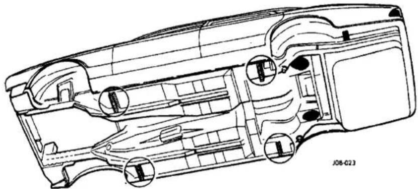
Fig. 3
2.1.3 Wheel-Free Lift
Use of a wheelfree lift is recommended for maintenance operations. Support the vehicle using lifting pads at the four jacking points (Fig. 3).
2
2.1.4 Workshops
2.1.4.1 Front - One Wheel
Position the jack under the lower spring support pan (Fig. 1), using a wooden block placed between the jack head and the spring support pan. Place an axle stand in position at the adjacent jacking point when the wheel has been raised.

2.1.4.2 Front - Both Wheels
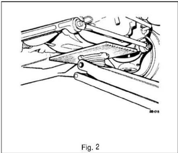
Position the jack centrally under the front crossmember (Fig. 2), using a wooden block placed between the jack head and the crossmember. Place axle stands under both front jacking points when the vehicle has been raised.
2.1.4.3 Rear - Both Wheels
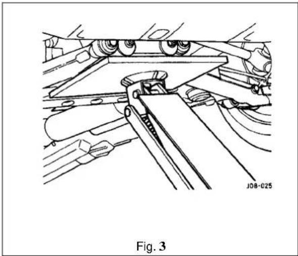
Place the jack centrally under the rear crossmember (Fig. 3), using a wooden block placed between the jack head and the crossmember. Place axle stands under both rear jacking points when the vehicle has been raised.

2.2 VEHICLE RECOVERY
2.2.1 General
Note: Prior to vehicle recovery, always ensure the vehicle keys are available and the vehicle security system is 'OFF'.
The safest and preferred method of vehicle recovery is by flat bed transporter, although a rear suspended tow may also be used.
The front and rear towing eyes are provided for use only in an emergency to move the vehicle if it is causing an obstruction, on police instructions, or, when winching the vehicle onto a recovery transporter.
Note: A towing shackle cannot be fastened to the front towing eye until the grille vane has been removed. To do this, remove the (three)quarter-turn fasteners securing the grille vane (Fig. 1), and place the vane safely to one side. The towing shackle may now be secured to the towing eye.

When the vehicle is being towed (see Towing Recovery), the gear lever must be set to neutral, 'N' (see Gear-shift Interlock) and the ignition key turned to position 'II' to release the steeringlock and render the indicators, horn and brake lights operational.
2.2.2 Gear-shift Interlock
The gear selector lever may only be moved from the park'P' position by turning the ignition key to position 'II' on the key switch and applying pressure to the footbrake pedal.
To remove the ignition key from the key switch, the gear selector lever must be moved to park 'P.
With the key removed, the gear selector lever will be locked in park'P'.
2.2.3 Gear-shift Interlock- Manual Override
In the event of electrical failure or when moving the vehicle without power, the gear selector lever can be manually unlocked from park'P'.
Below the left-hand side of the 'J' gate (Fig. 2), is the gear-shift interlock manual release catch. With a flat bladed screwdriver, remove the plug, arrowed (Fig. 2). Insert ignition key and press down catch whilst simultaneously moving the gear-shift lever from 'P' position.
Note: Gear-shift lever can only be moved approximately 25mm with the key still inserted.
Remove key and replace plug.


2.2.4 Transporting

If the vehicle is being transported on a trailer or flatbed transporter (Fig. 1), the handbrake must be applied, the wheels checked and if fitted with an automatic transmission, the gear selector lever moved to neutral, 'N' (see Gear-shift Interlock).

Fig. 1
CAUTION: Do not select 'P' because the parking lock mechanism may be damaged by the continuous slight forward and backward movement of the vehicle on the transporter.
There are four tie-down brackets on the vehicle underbody. Do not attach the tie down hooks of the transporter to the towing eyes of the vehicle.
2.2.5 Towing Recovery
Adhere to local regulations forthetowing of vehicles. Incertain countries the registration number of the towing vehicle and an 'ON TOW sign or warning triangle must be displayed in a prominent position at the rear of the vehicle which is being towed.
WARNING: WHEN THE ENGINE IS NOT RUNNING, THE STEERING AND BRAKES WILL NO LONGER BE POWER-ASSISTED. APPLICATIONS OF THE BRAKE PEDAL WILL GRADUALLY DEPRESSURIZE THE ACCUMULATOR. THEREFORE, BE PREPARED FOR HEAVY STEERING AND THE NEED FOR GREATLY INCREASED BRAKE PEDAL PRESSURE.
*The vehicle may be towed by another for a SHORT DISTANCE ONLY (maximum 0.8km/0.5mile), with the gear lever in neutral (N) provided that a speed of 48 km/h (30 mile/h) is not exceeded.
2.2.6 Vehicles with Defective Automatic Transmission:
The vehicle must be towed with the rear wheels clear of the ground, see suspended towing.
2.2.7 Suspended Towing
CAUTION: Do not tow with sling-type equipment as damage to the bodywork may result. Do not front suspend tow vehicles with automatic transmission.
2
2.2.8 Rear Suspended Tow
- Remove the ignition key from the ignition/steering lock.
- Raise the vehicle using a lifting device with a cradle. This should be positioned under each rear wheel as indicated in Fig. 1.

Fig. 1


SECTION CONTENTS
Sub-Section Title SRO Page
I to III. ...... Preliminary Pages .... .... .... .... .... .... .... .... .... ....
3.1.1 Engine, General....1
3.1.2. Engine/ Transmission Unit, Renew.... 12.41. 02/20 ... 2
3.1.3 .... OEnBrew 12.60.00 3
3.1.4 . . . . . . . . . . . . . . . . . . . . . . . . . . . . . . . . . . . . . . . . . . . . . . 12.60.04 3
3.1.5 Front Engine Mounting Bracket Assembly, Renew 12.45.01 LH
12.45.03 RH...4
3.1.6 . . ....Rear Engine Mounting Assembly, Renew . . . . . . . . . . . . . . . . . . . . . . . . . . . . . . . . . . . . . . . . . . . . . 12.45.04 ....4


TOOLS & EQUIPMENT
| Illustration | Jaguar Number | Description | Notes | |
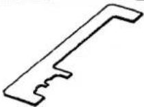 | 18G 1433 | Camshaft timing tool | ||
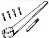 | 18G 1437 | Front pulley lock | ||
 | 18G 1465 | Engine lifting bracket | ||
 | MS 53C | Engine support beam | ||
| not illustrated | YA 992 | 'Snap-On' Oil filter canister removal tool | ||
II. TORQUE TIGHTENING SPECIFICATIONS
| Fixing | lightening Torque (Nm) |
| Air Cleaner | |
| Air box bracket screw | 8,5 - 11,5 |
| Air box to bracket | 9,5 - 12,5 |
| Air box to instrument | 9,5 - 12,5 |
| Air cleaner bracket setscrew | 63 - 87 |
| Air cleaner support bracket(4,0 liter, supercharged) | 8,5 - 11,5 |
| Air meter to intake gaiter (4,0 liter, supercharged) | 12 - 1,6 |
| Air temperature sensor to air box | 7 - 9 |
| Hose clamp, air box to air meter | 12 - 1,6 |
| Hose clamp, air box to body | 12 - 1,6 |
| Instrument bracket Taptite screw | 9,5 - 12,5 |
| Trumpet to body | 9,5 - 12,5 |
| Air Conditioning Compressor Mounting | |
| Belt tensioner assembly to compressor bracket | 22 - 28 |
| Compressor bracket to cylinder block | 22 - 28 |
| Compressor to bracket | 22 - 28 |
| Idler pulley to tensioner assembly | 22 - 28 |
| Cooling System | |
| Bypass elbow to thermostat housing | 95 - 12,5 |
| Fan drive unit setscrew | 12 - 16 |

| Fixing | lighteningTorque (Nm) |
| Cooling System (continued) | |
| Fan drive unit to pulley | 21,5 - 28,5 |
| Hose clamp, breather to thermostat | 1,5 - 25 |
| Hose clamp, breather to throttle body | 1,5 - 25 |
| Hose clamp, bypass hose | 25 - 35 |
| Hose clamp, water pump to pipe | 25 - 35 |
| Thermostat cover to housing | 2 1,5 - 28,5 |
| Thermostat to cylinder head | 21.5 - 28,5 |
| Water pipe bracket to inlet manifold | 21,5 - 28,5 |
| Water pump assembly | 21,5 - 28,5 |
| Water pump to timing cover | 21,5 - 28,5 |
| Water pump to water rail | 25 - 35 |
| Water rail to cylinder block | 21,5 - 28,5 |
| Water temperature sensor to thermostat housing | 14,5 - 19,5 |
| Water temperature transmitter to thermostat housing | 14,5 - 19,5 |
| Engine Mounting | |
| Engine mounting bracket screw | 44,5 - 59,5 |
| Exhaust Manifold | |
| Exhaust manifold to cylinder head | 44,5 - 59,5 |
| Heatshield to exhaust manifold | 21,5 - 28,5 |
| Lifting eye setscrew (slave item only) | 21,5 - 28,5 |
| Miscellaneous Hoses | |
| Hose clamp, heater return hose to throttle body | 1,5 - 25 |
| Hose clamp, hose to cam cover | 25 - 35 |
| Hose clamp, water pump | 25 - 35 |
| Oil Cooler(4,0 liter supercharged) | |
| Hose clamp, oil cooler hose to radiator cradle | 7 - 10 |
| Oil cooler clamp screw | 5 - 7 |
| Oil cooler pipe bracket screw | 1,5 - 25 |
| Oil cooler pipes to engine | 14 - 18 |
| Oil cooler to body | 17 - 23 |
| Tube nut, all except those shown below | 17 - 23 |
| Tube nut, transmission pipesto transmission | 16 - 20 |
| Oil Pump, Filter & Oil Pan | |
| Drain plug | 64,8 - 79,2 |
| Filter head to cylinder block | 21,5 - 28,5 |
| Oil filter cartridge | 12 - 15 |
| Oil pan to cylinder block | 21,5 - 28,5 |
| Oil pan to timing cover | 21,5 - 28,5 |
| Oil pump and oil pump carrier to cylinder block | 21,5 - 28,5 |
| Rear cover to body | 9,5 - 12,5 |
| Relief valve plug | 35,7 - 48,3 |
| Supercharger | |
| Adapter to timing cover | 22 - 28 |
| Air duct clamp to intercooler | 25 - 35 |
| Air duct hoses | 25 - 35 |
| Air duct lower to intercooler | 25 - 35 |
3.1


3.1
| Fixing lightening Torque | (Nm) |
| Supercharger (continued) | |
| Air duct upper casting to lower | 25 -35 |
| Bypass valve disc to spindle | 25 -35 |
| Bypass valve to throttle body | 85 -11,5 |
| Elbow to intercooler | 22 -28 |
| Idler bracket/ timing cover to cylinder black | 22 -28 |
| Idler bracket to water pump | 22 -28 |
| Idler mounting bracket to thermostat housing | 22 -28 |
| Intercooler water pipes | 22 -28 |
| Outlet elbow to supercharger | 22 -28 |
| Pulley to carrier | 22 -28 |
| Supercharger mounting bracket to engine | 43 -57 |
| Supercharger mounting stud | 22 -28 |
| Supercharger to mounting bracket | 43 -57 |
| Tensioner bracket/ timing cover to cylinder block | 22 -28 |
| Tensioner bracket to adapter | 22 -28 |
| Throttle body adapter to bypass actuator | 8,5 -11,5 |
- SERVICE MATERIALS
| Description | Uses | Notes |
| Hylosil 102 sealant | Half moon seals to cylinder head | |
| Oil pick-up strainer to transfer housing | ||
| Oil pump transfer housing to cylinder block | ||
| Rear seal housing to cylinder block | ||
| [Thermostat housing to extension] | ||
| Thermostat outer housing to inner housing | ||
| [Timingcover blanking plate to timing cover] | ||
| Timing cover to cylinder block | ||
| Locktite 501 locking compound | Oil pump drive plate bolt | |
| Oil pump front cover to body | ||
| Oil pump rear cover to body | ||
| Tivoli Kay Adhesives No. 5696 sealant | Exhaust system joints |

3.1.1 ENGINE, GENERAL
The 3.2/4,0 liter normally aspirated and the 4.0 liter supercharged engined vehicles are equipped with the AJ16 family of six cylinder in-line engines. The engines have a fully mapped engine management system with digital ignition and individual on-plug ignition coils.
This section describes the service procedures to be carried out with the engine in situ. It also covers the renewal of the engine/ transmission unit.
For information relating to stripdown, inspection, fault diagnosis, renovation and rebuild work, refer to the AJ16 Engine Service Manual.


3.1.2 ENGINE / TRANSMISSION UNIT, RENEW
SRO 12.41.02 / 20
The engine /transmission unit on the AJ 16 normally aspirated and supercharged engined vehicles are fitted onto three engine mounting/bracket assemblies. The two front engine mountings for the 3.2/4.0 liter normally aspirated and the 4.0 liter supercharged engined vehicles are identical. They are fitted to the front crossmember on either side of the engine bay. Rubber to metal engine/transmission rear mounts used for both engine types, are secured to a support bracket which traverses the two body underframe longitudinal members. For access to remove the engine carry out the following procedures:
WARNING: WHEN WORKING WITHIN THE ENGINE COMPARTMENT, KEEP CLEAR OF THE RADIATOR COOLING FANS AS THEY COULD START WITHOUT WARNING EVEN IF THE ENGINE IS NOT RUNNING.
■ Remove the hood, see SRO 76.16.01, section 13
■ Remove the air cleaner assembly.
■ Depressurize the fuel system, see SRO 19.50.02, section 5.1.
- Disconnect the battery.
- In line with the relevant SRO's and sections, remove all appropriate obstructing parts, including their fixing and mounting arrangements.
■ Disconnect all mechanical and isolate all electrical linkages leading to and from the engine.
■ De-gas the airconditioning system, see section 14, Charge Recovery (System depressurization).
CAUTION: Do not vent refrigerant directly to the atmosphere and always use Jaguar approved recovery/recycle/recharge equipment.
■ Drain the engine oil, see 3.1.3 this section.
■ Drain the coolant, see SRO 26.10.01, section 4.1.
WARNING: DO NOT REMOVE THE HEADER TANK PRESSURE CAP WHILE THE ENGINE IS HOT. IF THE CAP MUST BE REMOVED, PROTECT THE HANDS AGAINST ESCAPINGSTEAM AND SLOWLY TURN THE CAP ANTI-CLOCKWISE UNTIL THE EXCESS PRESSURE CAN ESCAPE. LEAVE THE CAP IN THIS POSITION UNTIL ALL STEAM AND PRESSURE HAS ESCAPED AND THEN REMOVE THE CAP COMPLETELY.
Before lifting the complete engine / transmission unit with an engine hoist from the engine bay, ensure that two engine lifting brackets (tool 18G. 1465) are secured equally spaced to the inlet manifold studs. The engine lifting brackets should be positioned towards the front and the rear of the assembly. Ensure the front of the vehicle is jacked up securely on stands when removing the assembly.

3.1.3 ENGINE OIL, RENEW
SRO 12.60.00
■ Undo and remove the sump plug positioned at the rear of the sump, drain the engine oil into a suitable receptacle and dispose of it in a safe and environmentally friendly manner.
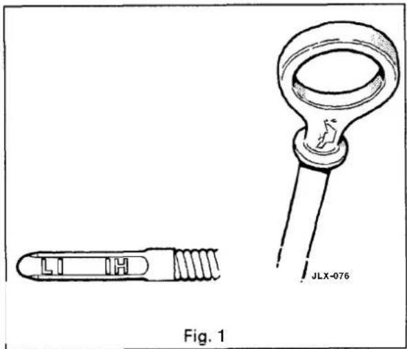
■ Replenish the engine oil, to the correct level on the dipstick (see Fig. 1).
- When the oil is renewed, start the engine, wait for the oil light to extinguish and switch off the engine for 30 seconds.
■ Finally remove and wipe clean the dip stick,
- check the oil level– replenish if necessary.
■ For recommended engine oil refer to Appendix A1.
3.1

3.1.4 OIL FILTER CARTRIDGE, RENEW
SRO 12.60.04
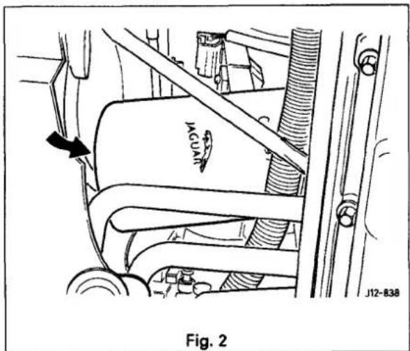
The white oil filter cartridge displaying the Jaguar logo, is located on the left-hand side of the engine below the throttle assembly (Fig. 2).
When refitting, tighten the oil filter cartridge using hand pressure only.
On no account use an oil filter strap designed for the removal of cartridges.
Note: The normal tightening torque of the oil filter is a 3/8 to 1/2 turn after initial contact.

3.1.5 FRONTENGINE MOUNTING BRACKETASSEMBLY, RENEW
SRO 12.45.01 LH
SRO 12.45.03RH
3.1
Each of the two engine mounting bracket assemblies comprises a mounting rubber (1 Fig. 1) with an insulator (2 Fig. 1) clamped between two brackets (3&4 Fig. 1).
The front of the engine complete with attached mounting bracket assemblies is seated on support brackets welded to the front crossmember and is secured to the brackets by a single fixing arrangement comprising nuts, bolts and washers.
■ Jack up the vehicle and secure the engine hoist (Service Tool MS53 C) to lifting eyes of the front engine lifting brackets.
■ Remove the front engine mounting bracket assembly to front crossmember fixing screws. These can be accessed via two round openings positioned underneath the crossmember.
- Remove any obstructing parts preventing the front end of the engine from being lifted from its seating.
- Lift the front end of the engine/transmission unit slightly and detach the front mounting bracket assemblies from the lower engine housing.

3.1.6 REAR ENGINE MOUNTING ASSEMBLY RENEW
SRO 12.45.04
The rear engine mounting assembly comprises a rubber to metal engine/transmission rear mount (1 Fig. 2) secured to a support bracket (2 Fig. 2) by a single fixing arrangement.
■With the aid of the engine hoist (ServiceTool MS53C) secured to the lifting eyes of the rear engine lifting brackets, and a jack positioned under the rear mounting bracket, take the weight of the engine.
■ Undo and remove the fixing arrangement securing the rear engine mounting bracket assembly.
■ Lower the jack and remove assembly.
■ Dismantle the assembly, cleanall components and examine for any signs of wear or damage.
Renew components as necessary.

SECTION CONTENTS
Sub-Section Title SRO Page
I to III ...... Preliminary Pages ...... i
3.2.1 Engine, General 1
3.2.2.... Engine/ Transmission Unit, Renew.... 12.37.01/90....2
3.2.3 Engine Oil, Renew 12.60.00 3
3.2.4 Oil Filter Canister, Renew 12.60.04 3
3.2.5... Oil Cooler 12.60.68 4
3.2.6 ...... Front Engine Mounting Bracket Assembly, Renew ...... 12.45.01 LH
12.45.03RH ..... 4
3.1.7 Rear Engine Mounting Assembly, Renew 12.45.08 5
3.2


I. SERVICE TOOLS & EQUIPMENT
| Illustration | Jaguar Number | Description | Notes | |
 | JD 183 | Quick-fit pipe disconnecting tool | ||
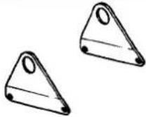 | 18G 1465 | Engine lifting bracket | ||
 | MS 53C | Engine support beam | ||
| not illustrated | YA 992 | 'Snap-On' Oil filter canister removal tool | ||
II. TORQUE TIGHTENING SPECIFICATIONS
| Fixing lightening Torque | (Nm) |
| Oil cooler to body | 17-23 |
| Oil cooler hose clamp to radiator cradle | 7-10 |
| Oil cooler pipes to engine | 17-23 |
| Heat shield to hydraulic mount | 4-5 |
| Hose clamp - hose to air cleaner and induction elbow | 3-4 |
- SERVICE MATERIALS
| Description | Uses | Notes |
| Hylosil 102 sealant | Filler cap 'Oring | |
| Vaseline or Silicon 5000 | Top of oil filler tube | |
| Tivoli Kay Adhesives No. 5696 sealant | Exhaust system joints |

3.2.1 ENGINE, GENERAL
The twelve cylinder, vee formation engine has a capacity of 6.0 liters. Each cylinder bank has a single overhead camshaft and two valves percylinder. The engine has a fully mapped engine management system with digital ignition and two ignition coils.
This section describes the service procedure to be carried out with the engine in situ. It also covers the renewal of the engine/ transmission unit.
For information relating to strip-down, inspection, fault diagnosis, renovation and rebuild work, refer to the V12 Engine Service Manual.
3.2


3.2.2 ENGINE - GEARBOX/TRANSMISSION ASSEMBLY, RENEW
SRO 12.37.01/90
The engine /transmission unit on the V12 6.0 liter model is mounted on three engine mounting/ bracket assemblies fitted to the front crossmember on either side of the engine bay. The engine/transmission rear mount is a mounting bracket and spring assembly fitted and secured to body underframe longitudinal members. For access to remove the engine carry out the following procedures:
3.2
WARNING: WHEN WORKING WITHIN THE ENGINE COMPARTMENT, KEEP CLEAR OF THE RADIATOR COOLING FANS AS THEY COULD START WITHOUT WARNING, EVEN IF THE ENGINE IS NOT RUNNING.
■ Remove the hood, see SRO76.16.01, section 13.
■ Remove the two air cleaner assemblies, see SRO's 19.10.01 & 19.10.02.
■ Remove the engine cover, see SRO 12.29.93 (V12 Engine Service Manual).
■ Depressurizethe fuel system, see SRO 19.50.02, section 5.1.
■ Disconnect the battery.
- In line with the relevant SRO's and sections, remove all appropriate obstructing parts, including their fixing and mounting arrangements.
■ Disconnect all mechanical and isolate all electrical linkages leading to and from the engine.
■ De-gas the air conditioning system, see section14, Charge Recovery (System depressurization).
CAUTION: Do not vent refrigerant directly to the atmosphere and always use Jaguar approved recovery/recycle/recharge equipment.
- Drain the engine oil, see 3.2.3 this section.
- Drain the coolant, see SRO 26.10.01, section 4.1.
WARNING: DO NOT REMOVE THE HEADER TANK PRESSURE CAP WHILE THE ENGINE IS HOT. IF THE CAP MUST BE REMOVED, PROTECTTHE HANDS AGAINST ESCAPINGSTEAM AND SLOWLY TURN THE CAP ANTI-CLOCKWISE UNTIL THE EXCESS PRESSURECAN ESCAPE. LEAVETHE CAPINTHIS POSITION UNTIL ALL STEAM AND PRESSURE HAS ESCAPED AND THEN REMOVE THE CAP COMPLETELY.
Before lifting the complete engine / transmission unit with an engine hoist from the engine bay, ensure that two engine lifting brackets (tooh 8G. 1465) are secured equally spaced to the inlet manifold studs. The four engine lifting brackets should be positioned towards the front and the rear of the assembly. Ensure the front of the vehicle is jacked up securely on stands when removing the assembly.

3.2.3 ENGINE OIL, RENEW
SRO 12.60.00
■ Undo and remove the sump plug positioned at the rear of the sump, drain the engine oil into a suitable receptacle and dispose of it in a safe and environmentally friendly manner.
■ Replenishtheengineoiltothecorrect level(1 Fig. 1) on the dipstick.
Note: If the 'O' ring on the on the filler cap is damaged, remove the 'O' ring and clean the groove. Secure a new 'O' ring in position using silicon sealant. Treat the screw threads with copper grease, and grease the top face of the oil filler with Hylosil lubricant.
- When the oil is renewed, start the engine, wait for the oil light to extinguish and switch off the engine for 30 seconds.
■ Finally remove and wipe clean the dip stick
■ (Fig. 1), check the oil level-replenish as necessary.
For recommended engine oil refer to Appendix AI.


3.2.4 OIL FILTER CARTRIDGE, RENEW
SRO 12.60.04
The white oilfilter cartridge displaying the Jaguar logo, is- cated on the lower lefthand side of the engine, near side of the sump. Access for removing the cartridge is from under- neath the vehicle (Fig. 2).
Removethe catalyst heat shield (where fitted) and use a coil spring type filter wrench to remove the cartridge.
Start and run the engine for a few seconds to charge the filter, then stop the engine and check the oil level. Replenish as necessary.


3.2.5 OIL COOLER, RENEW
SRO 12.60.68
The oil cooler is located below the radiator, behind the front bumper and is fitted to the radiator lower mounting using two securing bolts. The cooler feed pipe comprising several sections and return pipe (Fig. 1) are connected to the oil cooler by means of easily detachable quick-fit connectors.

3.2
3.2.6 FRONT ENGINE MOUNTING BRACKET ASSEMBLY, RENEW
SRO 12.45.01 LH
SRO 12.45.03 RH
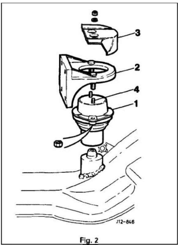
Each of the two engine mounting bracket assemblies comprises a hydraulic mount (1) secured to an engine side mounting bracket (2) which in turn is bolted to the lower engine housing. The engine mounting heat shield (3) is fixed to the hydraulic mount studs (4), protruding through the centre hole of the engine side mounting bracket.
The front of the engine complete with attached mounting bracket assemblies is seated on support brackets welded to the front crossmember and is secured to the brackets by a single fixing arrangement comprising bolts and washers.
■ Jack up the vehicle and secure the engine hoist (Service Tool MS53 C) to lifting eyes of the front engine lifting brackets
- Remove the front engine mounting bracket assembly to front crossmember fixing bolts. These can be accessed via two round openings positioned underneath the cross-member.
- Remove any obstructing parts preventing the front end of engine from being lifted from its seating.
- Lift the front end of the engine/transmission unit slightly and detach the front mounting bracket assemblies from the lower engine housing.

3.2.7 REARENGINE MOUNTING ASSEMBLY, RENEW
SRO 12.45.04
The rear engine mounting assembly (Fig. 1) comprises a mounting bracket and spring assembly, secured to bodyunderframe longitudinal members using nuts and washers.
- With the aid of the engine hoist (ServiceTool MS53 C) secured to the lifting eyes of the rear engine lifting brackets, and a jack positioned under the rear mounting bracket take the weight of the engine.
■ Undo and remove the mounting bracket and spring assembly fixing arrangement.
■ Lower the jack and remove assembly.
■ Dismantle the assembly, clean all components and examine for any signs of wear or damage.
■ Renew components as necessary.



SECTION CON TENTS
Sub-Section Title SRO Page
I to IV ...... Preliminary Pages ...... i
4.7.7 Cooling System Description 7
4.1.7.7 Cooling System Description. Major Components 7
4.7.7.2 Cooling System Description. Components for Climate Control System 7
4.7.1.3 Cooling System Description. Components for Supercharged Engine 7
4.7.7.4 Cooling System Description. Operation 7
4.7.2 Cooling System Configuration 2
4.7.3 Service Procedures 3
4.7.3.7 Service Procedures. Safety Precautions 3
4.7.3.2 Service Procedures. Working Practices 3
4.7.3.3 Service Procedures. Coolant Change 3
4.7.4. Drain and Fill Procedures 4
4.7.4.7 Drain and Fill Procedures. Radiator, Drain 4
4.7.4.2 Drain and Fill Procedures. Engine. Drain 4
4.1.4.3 Drain and Fill Procedures. Radiator, Fill 4
4.7.4.4 Drain and Fill Procedures. Complete System. Fill 5
4.7.5 Fault Diagnosis 6
4.1.5.7 Fault Diagnosis. Introduction 6
4.7.5.2 Fault Diagnosis. Diagnostic Procedures 6


1. SERVICE TOOLS & EQUIPMENT
No Jaguar servicetools are required for working on the cooling system. Some normal workshop items will be required, including a pressure tester, hydrometer and thermometer.
4.1
| Fixing | Tightening Torque (Nm) |
| Fan cowl assembly to radiator | 8-9 |
| Header tank bracket to body | 7-10 |
| Header tank to body | 2,5-3,5 |
| Hose clip, all except those shown below | 2,5-3,5 |
| Hose clip, bleed hose to radiator | 1,5-2,5 |
| Lower radiator cradle to body | 7-10 |
| Radiator drain plug | 1,5-2,5 |
| Radiator temperature switch | 13-17 |
| Supercharger pump mounting | 7-10 |
| Supercharger pump to instrumounts | 5-7 |
| Supercharger radiator to body | 7-10 |
| Top radiator panel to body | 7-10 |
- SERVICE MATERIALS
| Description | Uses | Notes |
| To be issued |
IV. SERVICE DATA
| Application | Specification |
| Engine thermostat temperature rating | 88°C |
| Coolant header cap pressure rating | 12bar |
| Generator / water pump drive belt tension, new belt | Set to: (Burroughs method) 556 to 578 N; (Clavismethod) 174 to 180 Hz. Run for one minute and allow belt to cool. Reset to: (Burroughs method) 511 to 534 N; (Clavismethod) 167 to 173 Hz |
| Generator / water pump drive belt tension, service tension | Burroughs method: 511 to 534 N. Clavis method: 167 to 173 Hz |
| Generator / water pump drive belt tension measuring point | Mid –way between crankshaft and generator pulleys |

4.1.1 COOLING SYSTEM DESCRIPTION
4.1.1.1 Major Components
- Main engine crossflow radiator, incorporating a concentric tube cooler for the power steering fluid mounted in the right-hand radiator side tank. Vehicles with automatic transmission have a transmission fluid cooler mounted in the lefthand radiator side tank; for 4,0 liter supercharged engines six-plate cooler is fitted; other vehicles have a tube-type cooler. Adouble -action temperature switch, for controlling the radiator cooling fans, is mounted in the lefthand radiator side tank.
- Two electrically operated radiator cooling fans, mounted behind the main radiator.
Coolant circulating pump, belt driven from the engine crankshaft.
Coolant header tank with pressure relief cap and coolant level probe. - Engine thermostat.
4.1.12 Components for Climate Control System
- Heater matrix.
- Electrically operated coolant circulating pump, mounted on the left-hand side of the engine bulkhead.
- Solenoid operated valve, located adjacent to the coolant circulating pump.

4.1.1.3 Components for Supercharged Engine
Supercharger crossflow radiator, mounted in front of the main radiator. The supercharger radiator is reverse-circuited, i.e. the coolant inlet is at the bottom of the radiator.
- Electrically operated coolant circulating pump, located at the left-hand side of the main radiator.
4.1.1.4 Operation
The configuration of the cooling system for normally aspirated and supercharged(4,0 liter) engines is shown in Sub-section 4.1.2.
The cooling system is pressurized, which allows the system to operate at a higher temperature without overheating. The header tank is fitted with a pressure relief cap to protect the system against overpressure.
Undercold start conditions, coolant is forced by the engine-driven water pump through the cylinder block and cylinder head to the thermostat housing. The thermostat is closed to give rapid engine warm up, hence the coolant is returned directly to the water pump inlet. When normal engine operating temperature is reached, the thermostat opens and coolant is diverted through the radiator before returning to the water pump inlet. In vehicles fitted with a supercharger, coolant is circulated through the supercharger radiator and intercooler by the supercharger water pump. The supercharger cooling circuit uses the same coolant header tank as the main engine cooling system.
The radiator cooling fans operate in series and parallel under the control of the double-action radiator mounted temperature switch. The fans are also controlled by the climate control system on vehicles fitted with air conditioning. Under hot operating conditions, the fans may continue to operate after the engine has been switched off. The fans stop automatically when the coolant temperature has been reduced sufficiently.

The system also provides the coolant supply for the climate control system, which is described in Section 14.

The configuration of the cooling system for normally aspirated and supercharged engines is shown in Fig. 1 and Fig. 2. The main coolant flows, with the system at normal operating temperature (i.e. with the engine thermostat open), are indicated by arrows.

- Header Tank
- Radiator
-
Water Pump
-
Thermostat
- Throttle Body
-
Engine
-
Heater
- Heater Pump
- Heater Valve
Fig. 1 Cooling System, Normally Aspirated Engine
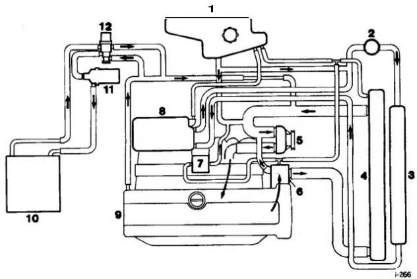
- Header Tank
- Supercharger Pump
- Supercharger Radiator
-
Main Radiator
-
Water Pump
- Thermostat
- Throttle Body
-
Intercooler
-
Engine
- Heater
- Heater Pump
- Heater Valve
Fig. 2 Cooling System, Supercharged Engine
4.1.3 SERVICE PROCEDURES
4.1.3.1 Safety Precautions
The anti-freeze specified in Appendix A I must be used wherever possible. It is designed to afford the maximum corrosion protection to all metals found in the engine cooling system, as well as having the frost protection properties necessary during the winter months.
Should it not be available, then anti-freeze conforming to Ford Motor Company specification ESD-M97B49-A may be used. To provide optimum temperature and corrosion protection, the specified anti-freeze concentration must always be used.
Once coolant has been drained from the system, it must be discarded and not re-used. Anti-freeze is harmful to the environment. Used coolant must be disposed of safely and never poured down a drain connected to the public sewer.
CAUTION: Never fill or top-up the system with water only.
4.1
CAUTION: Anti-freeze is harmful to paintwork. Coolant spillages must be wiped up immediately and the affected area washed to remove all traces of coolant.
CAUTION: To prevent the possibility of damage to the heater circuit pump and supercharger pump (where fitted), the pumps should be electrically isolated if the ignition has to be turned ON while the cooling system is drained.
WARNING: DO NOT REMOVE THE HEADER TANK PRESSURE CAP WHILE THE ENGINE IS HOT. IF THE CAP MUST BE REMOVED, PROTECT THE HANDS AGAINST ESCAPINGSTEAM AND SLOWLY TURN THE CAP ANTI-CLOCKWISE UNTIL THE EXCESS PRESSURE CAN ESCAPE. LEAVE THE CAP IN THIS POSITION UNTIL ALL THE STEAM AND PRESSURE HAS ESCAPED AND THEN REMOVE THE CAP COMPLETELY.
WARNING: WHEN DRAINING THE COOLANT WITH THE ENGINE HOT, PROTECT THE HANDS AGAINST CONTACT WITH HOT COOLANT.
WARNING: WHEN WORKING WITHIN THE ENGINE COMPARTMENT, KEEP CLEAR OF THE RADIATOR COOLING FANS. THE FANS COULD START WITHOUT WARNING EVEN IF THE ENGINE IS NOT RUNNING.
4.1.3.2 Working Practices
Whenfilling thesystem withcoolant, ensure that the vehicleisstanding on a level surfaceandthatthecoolant is poured in slowly so that airlocks are not introduced into the system. Airlockscan seriously affect the operation of the climate control system and can cause damage to the heater circuit pump (and supercharger circuit pump if fitted).
Hose clips should always be positioned so that there is proper access for tightening and that the clip does not foul or interfere with the operation of any components.
Drive belts must always be tensioned to the specified value and the tension checked at the correct point on the belt. This information is given in Subsection IV in the preliminary pages.
When tightening components, the torque figures given in Sub-section II in the preliminary pages should always be used for the fastenings listed.
4.1.3.3 Coolant Change
The coolant must be changed at intervals of four years. The system should be drained from the radiator drain plug, flushed and filled with fresh coolant. Flushing should be carried out thoroughly to remove all the old coolant from the engine and heater matrix. (The heatervalve is open with the ignition OFF). After filling, check the coolant concentration with a hydrometer. For the specified anti-freeze and coolant concentration, see Appendix AI.
4.1.4 DRAIN AND FILL PROCEDURES
4.1.4.1 Radiator, Drain
■ Place a drain tray in position under the radiator drain plug (Fig. 1).
■ Removethe header tank pressurecap. Release the captive radiator drain plug and drain the coolant.
■ Tighten the radiator drain plug.
CAUTION: This procedure does not drain the heater circuit.

4.1
4.1.4.2 Engine, Drain
Note: This procedure should only be necessary when the engine is being dismantled.
■ Drain the radiator. (See the procedure above).
■ Place a drain tray under the cylinder block drain plug (Fig. 2).
■ Remove the block drain plug and drain the coolant.
■ Fit the block drain plug.

WARNING: DO NOT REMOVE THE HEADER TANK PRESSURE CAP WHILE THE ENGINE IS HOT. IF THE CAP MUST BE REMOVED, PROTECT THE HANDS AGAINST ESCAPINGSTEAM AND SLOWLY TURN THE CAP ANTI-CLOCKWISE UNTIL THE EXCESS PRESSURE CAN ESCAPE. LEAVE THE CAP IN THIS POSITION UNTIL ALL THE STEAM AND PRESSURE HAS ESCAPED AND THEN REMOVE THE CAP COMPLETELY.
WARNING: WHEN DRAINING THE COOLANT WITH THE ENGINE HOT, PROTECT THE HANDS AGAINST CONTACT WITH HOT COOLANT.
4.1.4.3 Radiator, Fill
■ Add coolant until the level in the header tank is steady at MAX. (Do not fit the header tank cap).
■ Switch on the ignition. (Theclimate control system must be OFF).
- Start the engine and wait until the cooling fans operate for the second time. (The engine speed may be raised to reduce the warm up time).
■ While the cooling fans are operating, raise the engine speed to 1500 RPM for one minute. Return to idle speed.
■Switch off the ignition and wait for one minute.
- Check that the coolant level in the header tank is between MAX and 10 mm aboveMAX. Add coolant as necessary.
■ Fit the header tank cap.

4.1.4.4 Complete System, Fill
■ Add coolant until the level in the header tank is steady at MAX. (Do not fit the header tank cap).
- Switch on the ignition. (The climate control system must be OFF).
- Start the engine and wait until the cooling fans operate for the second time. (The engine speed may be raised to reduce the warm up time).
■ While the cooling fans are operating, raise the engine speed to 1500 RPM for one minute. Return to idle speed.
■ Turn the climate control system ON. Set the temperature to HI. Manually select a fan speed of approximately 50%.
- Run the engine for four minutes. Ensure that the climate control system outlet air temperature is hot to very hot and that there is no noise from the heater coolant circulating pump. (The engine speed may be raised to assist with heating).
■ Switch off the ignition and wait for one minute.
■ Check that the coolant level in the headertank is between MAX and 10 mm above MAX. Add coolant as necessary.
• Fit the header tank cap.
4.1


4.1.5 FAULT DIAGNOSIS
4.1.5.1 Introduction
The following diagnostic procedures are provided to assist properly qualified persons to identify and rectify the faults in the system which are most likely to be encountered. Reference is made to the Electrical Diagnostic Manual (EDM), which should be consulted for all electrical faults. When investigating faults relating to temperature, the prevailing ambient temperature conditions should be taken into account. The climate control system is dealt with in Section 14.
4.1.5.2 Diagnostic Procedures
| Symptom | Possible Cause | Check | Remedy |
| Overheating | Thermostat stuck closedIncorrect thermostat ratingFaulty temperature gaugeFaulty temperature transmitterRadiator core blockedRadiator grille obstructedConcentration of anti-freeze too highDrive belt slackDrive belt brokenWater pump seizedInsufficient coolantInternally collapsed hosesIncorrect ignition timingFuel/air mixture too weakIncorrect valve timingCylinder head gasket leakingBrakes binding | Test thermostatCheck thermostat operating temperatureRefer to EDMRefer to EDMCheck for hotspots in radiatorCheck grille for obstructionCheck strength of coolantCheck belt tensionVisual checkSlacken drive belt and turn water pump pulley by hand.Check belt for damageCheck coolant levelPressure test system and check for deformation of hosesRefer to EDMRefer to EDMCheck valve timingPressure -test system. (Check for contamination of coolantin header tank)Check brake calipers for sticking pistons and seized brake pad pins | Renew thermostatRenew thermostatRenew gaugeRenew transmitterFlush or renew radiatorRemove obstruction from grilleDrain and fillwith coolant of correct concentrationAdjust belt to correct tension or renew belt if wornRenew beltRenew water pump. Renew drive belt if requiredTop-up coolantRenew hoses as requiredRectify as requiredRectify as requiredCorrect valvetimingRenew head gasketRectify as required |
| Overheating at dle | Cooling fan(s) not operating | Refer to EDM | Rectify as required |
| Too cold | Thermostat stuck openIncorrect thermostat ratingThermostat not fittedCooling fan(s) operating continuouslyFaulty temperature gaugeFaulty temperature transmitter | Test thermostatCheck thermostat operating temperatureRemove thermostat housing and inspectRefer to EDMRefer to EDM | Renew thermostatRenew thermostatFit thermostatRectify as requiredRenew gaugeRenew transmitter |
| Loss of coolant | Loose clips on hosesHoses perished Visual checkRadiator core leaking PressureWater pumpseal leaking PressureThermostat gasket leaking PressureHeader tank cap defectivePorosity in castings PressureCorrosion caused by concentration of anti-freeze being too lowCylinder head gasket leakingCracked or damaged internal engine component | Check clips for correct tightness–test system–test system–test system. (Check for distortion of thermostat housing)Inspect cap or test cap spring pressure–test systemPressure–test system. Check strength of coolantPressure–test system. Check for contamination of coolant and engine lubrication systemIdentify component(s) affected. (Check for contamination of engine lubrication system) | Tighten clips as requiredRenew hoses as requiredRepair or renew radiatorRenew water pumpRenew gasket. Renew housing if requiredRenew capRectify as requiredRectify as required. Drain and fill with coolant of correct concentrationRenew head gasketRectify as required |
4.1

SECTION CON TENTS
Sub-Section Title SRO Page
I to IV ...... Preliminary Pages ...... i
4.2.1 Cooling System Description 1
4.2.1.1 Cooling System Description. Major Components 1
4.2.1.2 Cooling System Description. Components for Climate Control System 1
4.2.1.3 Cooling System Description. Operation 1
4.2.2 Cooling System Configuration 2
4.2.3 Service Procedures 3
4.2.3.1 Service Procedures. Safety Precautions 3
4.2.3.2 Service Procedures. Working Practices 3
4.2.3.3 Service Procedures. Coolant Change 3
4.2.4 Drain and Fill Procedures 4
4.2.4.1 Drain and Fill Procedures. Radiator, Drain 4
4.2.4.2 Drain and Fill Procedures. Radiator, Fill 4
4.2.4.3 Drain and Fill Procedures. Complete System. Fill 4
4.2.4.4 Drain and Fill Procedures. System. Air Bleeding 4
4.2.5 Fault Diagnosis 5
4.2.5.1 Fault Diagnosis. introduction 5
4.2.5.2 Fault Diagnosis. Diagnostic Procedures 5

4.2


1. SERVICE TOOLS & EQUIPMENT
NoJaguar service tools are required for working on the cooling system. Some normal workshop items will be required, including a pressure tester, hydrometer and thermometer.
II. TORQUE TIGHTENING SPECIFICATIONS
| Fixing | Tightening Torque (Nm) |
| Electric fan assembly to body | 7-10 |
| Headertank bracket to body | 7-10 |
| Header tank to body | 2,5-3,5 |
| Hose clip, all main hoses | 2,5-3,5 |
| Hose clip, bleed hoses except those shown below | 1,5-2,5 |
| Hose clip, bleed hoses to header tank | 25-3,5 |
| Locator, fan cowl to radiator top panel | 8,5-11,5 |
| Lower radiator cradle to body | 7-10 |
| Radiator drain plug | 1,5-2,5 |
| Radiator temperature switch 13 | -17 |
| Receiver drier to cooling fan assembly | 2,5-3,5 |
| Top radiator panel to body | 7-10 |
III. SERVICE MATERIALS
| Description | Uses | Notes |
| Ito be issued |
IV. SERVICE DATA
| Application | Specification |
| Engine thermostat temperature rating | 88°C |
| Coolant header cap pressure rating | 12 bar |
| Water pump/ air injection pump drive belt tension | Burroughs method: new belt 650N. In service, if tension falls below 320N reset at 400 NClavis method: new belt 169 to 175 Hz. In service, if tension falls below 127Hz reset at 132 to 138 Hz. |
| Drive belt tension measuring point | Mid-way between crankshaft and air injection pump pulleys |

4.2.1 COOLING SYSTEM DESCRIPTION
4.2.1.1 MajoComponents
- Engine crossflow radiator, incorporating a concentrictube cooler for the power steering fluid mounted in the left-hand radiator side tank. Vehicles with automatic transmission have a six-plate transmission fluid cooler mounted in the right-hand radiator side tank. A double-action temperature switch, for controlling the electric radiator cooling fans, is mounted in the left-hand radiator side tank.
- Engine driven, viscous-coupled, radiator cooling fan
- Two electrically operated radiator cooling fans, mounted in front of the radiator.
Coolant circulating pump, belt driven from the engine crankshaft.
Coolant header tank with pressure relief cap and coolant level probe. - Two engine thermostats, one in each cylinder bank.
4.2.1.2 Components for Climate Control System
- Heater matrix.
- Electrically operated coolant circulating pump, mounted on the left-hand side of the engine bulkhead.
- Solenoid operated valve, located adjacent to the coolant circulating pump.
4.2

4.2.1.3 Operation
The configuration of the cooling system is shown in Sub-section 4.2.2.
The cooling system is pressurized, which allows the system to operate at a higher temperature without overheating. The header tank is fitted with a pressure relief cap to protect the system against overpressure.
Under cold start conditions, coolant is forced by the engine driven water pump through each cylinder block and cylinder head to the thermostat housings. The thermostats are closed to give rapid engine warm up, hence the coolant is returned via the engine cross pipe to the water pump inlet. When normal engine operating temperature is reached, the thermostats open and coolant is diverted through the radiator before returning to the water pump inlet.
If the engine driven fan is unable to provide sufficient cooling, the electrically operated fans operate in series and parallel under the control of the radiator mounted temperature switch. Under hot operating conditions, the electric fans may continue to operate after the engine has been switched off. The fans stop automatically when the coolant temperature has been reduced sufficiently.
The system also provides the coolant supply for the climate control system, which is described in Section 14.


The configuration of the cooling system is shown in Fig. 1. The main coolant flows, with the system at normal operating temperature (i.e. with the engine thermostats open), are indicated by arrows.

-
Header Tank
-
Radiator
-
Water Pump
-
Thermostat
-
Engine
-
Heater
-
Heater Pump
-
Heater Valve
Fig. 1 Cooling System Layout

4.2.3 SERVICE PROCEDURES
4.2.3.1 Safety Precautions
The anti-freezespecified in Appendix A1 must be used wherever possible. It is designed to afford the maximum corrosion protection to all metals found in the engine cooling system, as well as having the frost protection properties necessary during the winter months. Should it not be available, then anti-freeze conforming to Ford Motor Company specification ESD-M97B49-A may be used. To provide optimum temperature and corrosion protection, the specified anti-freezeconcentration must always be used. Once coolant has been drained from the system, it must be discarded and not reused. Anti-freeze is harmful to the environment. Always dispose of used coolant safely and never pour it down a drain connected to the public sewer.
CAUTION: Never fill or top-up the system with water only.
CAUTION: Anti-freeze is harmful to paintwork. Coolant spillages must be wiped up immediately and the affected area washed to remove all traces of coolant.
CAUTION: To prevent the possibility of damage to the heater circuit pump, the pump should be electrically isolated if the ignition has to be turned ON while the cooling system is drained.
4.2

WARNING: DO NOT REMOVE THE HEADER TANK PRESSURE CAP WHILE THE ENGINE IS HOT. IF THE CAP MUST BE REMOVED, PROTECT THE HANDS AGAINST ESCAPINGSTEAM AND SLOWLY TURN THE CAP ANTI-CLOCKWISE UNTIL THE EXCESS PRESSURE CAN ESCAPE. LEAVE THE CAP IN THIS POSITION UNTIL ALL THE STEAM AND PRESSURE HAS ESCAPED AND THEN REMOVE THE CAP COMPLETELY.
WARNING: WHEN DRAINING THE COOLANT WITH THE ENGINE HOT, PROTECT THE HANDS AGAINST CONTACT WITH HOT COOLANT.
WARNING: WHEN WORKING WITHIN THE ENGINE COMPARTMENT, KEEP CLEAR OF THE ENGINE DRIVEN RADIATOR COOLING FAN WHEN THE ENGINE IS RUNNING.
4.2.3.2 Working Practices
When filling the system with coolant, ensure that the vehicle is standing on a level surface and that the coolant is poured in slowly so that airlocks are not introduced into the system. Airlocks can seriously affect the operation of the climate control system and can cause damage to the heater circuit pump.
Hose clips should always be positioned so that there is proper access for tightening and that the clip does not foul or interfere with the operation of any components.
The drive belt must always be tensioned to the specified value and the tension checked at the correct point on the belt. This information is given in Sub-section IV in the preliminary pages.
When tightening components, the torque figures given in Sub-section II in the preliminary pages should always be used for the fastenings listed.
When fitting a replacement thermostat, ensure that the jiggle-pin is to the top of the thermostat housing.
4.2.3.3 Coolant Change
The coolant must be changed at intervals of four years. The system should be drained from the radiator drain plug, flushed and filled with fresh coolant. Flushing should be carried out thoroughly to remove all the old coolant from the engine and heater matrix. (The heatervalves open with the ignition OFF) After filling, check the coolant concentration with a hydrometer. For specified anti-freeze and coolant concentration, see in Appendix AI.

4.2.4 DRAIN AND FILL PROCEDURES
4.2.4.1 Radiator, Drain
■ Place a drain trayinposition under the radiator drainplug (Fig. 1).
■ Removethe headertank pressure cap. Releasethecaptive radiator drain plug and drain the coolant.
- Tighten the radiator drain plug.
CAUTION: This procedure does not drain the heater circuit.
WARNING: DO NOT REMOVE THE HEADER TANK PRESSURE CAP WHILE THE ENGINE IS HOT. IF THE CAP MUST BE REMOVED, PROTECT THE HANDS AGAINST ESCAPING STEAM AND SLOWLY TURN THE CAP ANTI-CLOCKWISE UNTIL THE EXCESS PRESSURE CAN ESCAPE. LEAVE THE CAP IN THIS POSITION UNTIL ALL THE STEAM AND PRESSURE HAS ESCAPED AND THEN REMOVE THE CAP COMPLETELY.
WARNING: WHEN DRAINING THE COOLANT WITH THE ENGINE HOT, PROTECT ME HANDS AGAINST CONTACT WITH HOT COOLANT.

4.2.4.2 Radiator, Fill
- Add coolant until the level in the header tank is steady at MAX. (Do not fit the header tank cap).
■ Switch on the ignition. (The climate control system must be OFF).
■ Start the engine and add coolant to the header tank if required to ensure that it does not empty.
■ Runthe engine until the temperature gauge reads normal. (The enginespeed may be raised to reduce warm uptime).
■ Switch off the ignition and wait for one minute. - Check that the coolant level in the header tank is between MAX and 10 mm above MAX. Add coolant as necessary.
■ Fit the header tank cap.
4.2.4.3 Complete System, Fill
■ Add coolant until the level in the header tank is steady at MAX. (Do not fit the header tank cap).
■ Switch on the ignition. (The climate control system must be OFF).
■ Start the engine and add coolant to the header tank if required to ensure that it does not empty.
- Run the engine until the temperature gauge reads normal, (The engine speed may be raised to reduce the warm up time).
■ Turn the climate control system ON. Set the temperature to HI. Manually select a fan speed of approximately 50%.
- Run the engine for four minutes. Ensure that the climate control system outlet air temperature is hot to very hot and that there is no noise from the heater coolant circulating pump. (The engine speed may be raised to assist with heating).
■ Switch off the ignition and wait for one minute.
- Check that the coolant level in the header tank is between MAX and 10 mm above MAX. Add coolant as necessary.
■ Fit the header tank cap.
4.2.4.4 System, Air Bleeding
After filling the system with coolant, any air present must be purged before effective cooling is possible. Provided the correct fill procedure has been followed, purging of the system takes place automatically as follows:
The air entrained by the coolant, rises to the top of the radiator and to the highest point on each side of the engine (the thermostat housings). While the thermostats are closed, the radiator is under reduced pressure due to the pump suction and air is bled through the jiggle-pins in each thermostat. Purged air is returned via the bleed system to the header tank. When normal operating temperature is reached, the thermostats open and the system operates normally.
4.2.5 FAULT DIAGNOSIS
4.2.5.1 Introduction
The following diagnostic procedures are provided to assist properly qualified personsto identify and rectify the faults in the system which are most likely to be encountered. Reference is made to the Electrical Diagnostic Manual(EDM), which should be consulted for all electrical faults. When investigating faults relating to temperature, the prevailing ambient temperature conditions should be taken into account. The climate control systemis dealt with in Section14.
4.2.5.2 Diagnostic Procedures
| Symptom | Possible Cause | Check | Remedy |
| Overheating | Thermostat(s) stuck closedIncorrect thermostat ratingFaulty temperature gaugeFaulty temperature transmitterRadiator core blockedRadiator grille obstructedConcentration of anti-freeze too highDrive belt slackDrive belt brokenWater pump seizedInsuff icient coolantInternally collapsed hosesIncorrect ignition timingFuel / air mixture too weakIncorrect valve timingCylinder head gasket(s) leakingBrakes binding | Test thermostat(s)Check thermostat operating temperatureRefer to EDMRefer to EDMCheck for hotspots in radiatorCheck grille for obstructionCheck strength of coolantCheck belt tensionVisual checkSlacken drive belt and turn water pump pulley by hand. Check belt for damageCheck coolant levelPressure test system and check for deformation of hosesRefer to EDMRefer to EDMCheck valve timingPressure -test system. (Check for contamination of coolant in header tank)Check brake calipers for sticking pistons and seized brake pad pins | Renew thermostat(s)Renew thermostat(s)Renew gaugeRenew transmitterFlush or renew radiatorRemove obstruction from grilleDrain and fill with coolant of correct concentrationAdjust belt to correct tension or renew belt if wornRenew beltRenew water pump. Renew drive belt if requiredTop-up coolantRenew hoses as requiredRectify as requiredRectify as requiredCorrect valve timingRenew head gasket(s) Rectify as required |
| Overheating at dle | Electric cooling fan(s) not operating | Refer to EDM | Rectify as required |
| Too cold | Thermostat(s) stuck openIncorrect thermostat ratingThermostat(s) not fittedElectric cooling fan(s) operating continuouslyFaulty temperature gaugeFaulty temperature transmitter | Test thermostat(s)Check thermostat operating temperatureRemove thermostat housing and inspectRefer to EDMRefer to EDMRefer to EDM | Renew thermostat(s)Renew thermostat(s)Fit thermostat(s)Rectify as requiredRenew gaugeRenew transmitter |
| .oss of coolant | Loose clips on hoses | Check clips for correct tightness | Tighten clips as required |
| Hoses perished | Visual check | Renew hoses as required | |
| Radiator core leaking | Pressure -test system | Repair or renew radiator | |
| Water pump seal leaking | Pressure -test system | Renew water pump | |
| Thermostat gasket(s) leaking | Pressure -test system. (Check for distortion of thermostat housing(s)) | Renew gasket. Renewhousing(s) if required | |
| Header tank cap defective | Inspect cap or test cap spring pressure | Renew cap | |
| Porosity in castings | Pressure -test system | Rectify as required | |
| Corrosion caused by concentration of anti-freeze being too low | Pressure -test system. Check strength of coolant | Rectify as required. Drain and fill with coolant of correct concentration | |
| Cylinder head gasket(s) leaking | Pressure -test system. Check for contamination of coolant and engine lubrication system | Renew headgasket(s) | |
| Cracked or damaged internal engine component | Identify component(s) affected. (Check for contamination of engine lubrication system) | Rectify as required |
SECTION CONTENTS
| Sub-Section | Title | SRO | Page |
| i | Preliminarypage. | 1 | |
| 5.1.1 | Fuel System layout | 1 | |
| 5.1.2 | General Description | 3 | |
| 5.1.3 | Fuel Rail/ Pressure Regulator Valve/ Injectors (Supercharged), Renew | 18.10.0118.10.0219.45.1119.60.13 | 5 |
| 5.1.4 | Fuel Rail / Pressure Regulator Valve/ Injectors (Normally Aspirated), Renew | 18.10.0118.10.0219.45.1119.60.13 | 7 |
| 5.1.5 | Purge Control Valve (All Models), Renew | 17.15.30 | 9 |
| 5.1.6 | Throttle Assembly (Supercharged), Renew | 18.30.1719.70.0419.70.07 | 10 |
| 5.1.7 | Idle Speed control Valve/ Gaskets (Supercharged), Renew | 18.30.7418.30.77 | 11 |
| 5.1.8 | Idle Speed Control Valve/ Gaskets (Normally Aspirated), Renew | 18.30.7418.30.77 | 12 |
| 5.1.9 | Fuel Cut Off Inertia Switch (All Models), Renew | 18.30.35 | 13 |


5.1.1 FUEL SYSTEM LAYOUT
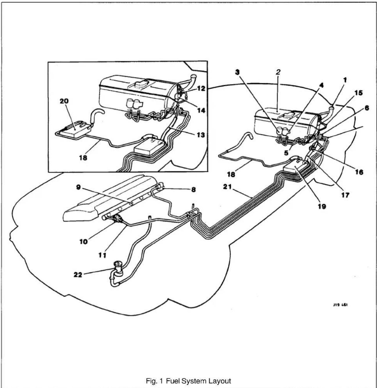
The above schematic illustration(Fig.1), shows the part and component layout of the fuel system of 4.0 liter normally aspirated engined vehicles. The inset view shows the differences in the component layout for NAS market vehicles only. This illustration is to be read with the table on Page 2.
Note: The layout of the supercharged vehicle is as shown in this illustration apart from the routing of the fuel feed line.
Key to Fig.1, Fuel System AJ16, page 1
| SRO | Component/ Parts | Location | Number |
| 19.55.13 | Fuel filler assembly | Rear deck area | 1 |
| 19.55.0 1 | Fuel tank | Behind rear bulkhead | 2 |
| 19.45.08 | Fuel pump(s) | Inside fuel tank | 3 |
| Fuel pump filter | Inside fuel tank | 4 | |
| 19.40.97 | Fuel feed line | Fuel pump to fuel filter | 5 |
| 19.25.02 | Fuel filter | Above rear axle assembly | 6 |
| 19.40.60 | Fuel feed line | Fuel filter to fuel rail | 7 |
| 19.60.13 | Fuel rail | Inlet manifold | 8 |
| 18.10.02 | Fuel injectors | Inlet manifold/ fuel rail | 9 |
| 19.45.11 | Fuel regulator valve | Mounted on the fuel rail | 10 |
| 19.40.85 | Fuel return line | Fuel regulator to fuel tank | 11 |
| Emission vent line | Fuel tank to running loss control valve (NAS 4.0L normally aspirated engine only) | 12 | |
| Emission vent line | Running loss control valve to primary carbon canister (NAS 4.0L normally aspirated engine only) | 13 | |
| Running loss control valve (NAS only) | Left side of the fuel tank | 14 | |
| Emission vent line | Fuel tank to tank pressure control (Rochester) valve | 15 | |
| 17.15.4 1 | Tank pressure control (Rochester) valve | Connected between emission vent lines as shown on schematic | 16 |
| Emission vent line | Rochester valve to primary carbon canister | 17 | |
| Emission vent line | Primary carbon canister to secondary carbon canister (NAS 4.0L normally aspirated engine only) | 18 | |
| Emission vent line | Primary carbon canister to atmosphere | 18 | |
| 17.15.13 | Primary carbon canister | Left side of vehicle, in front of the rear axle | 19 |
| 17.15.13 | Secondary carbon canister | To the right of the primary carbon canister on the other side of the vehicle (NAS 4.0L normally aspirated engine only). | 20 |
| Emission vent line | Primary carbon canister to purge valve | 21 | |
| 17.50.30 | Purge valve | Below the left head lamp module | 22 |
5.1.2 GENERAL DESCRIPTION
WARNING: WORKING ON THE FUEL SYSTEM MAY RESULT IN FUEL AND FUEL VAPOUR BEING PRESENT IN THE ATMOSPHERE. FUEL VAPOUR IS EXTREMELY FLAMMABLE, HENCE GREAT CARE MUST BE TAKEN WHILST WORKING ON THE FUEL SYSTEM. ADHERE STRICTLY TO THE FOLLOWING PRECAUTIONS:
DO NOT SMOKE IN THE WORK AREA.
DISPLAY 'NO SMOKING' SIGNS AROUND THE AREA.
ENSURE THAT A CO2 FIRE EXTINGUISHER IS CLOSE AT HAND.
ENSURE THAT DRY SAND IS AVAILABLE TO SOAK UP ANY FUEL SPILLAGE.
EMPTY FUEL USING SUITABLE FIRE PROOFEQUIPMENT INTO AN AUTHORIZED EXPLOSION-PROOF CONTAINER.
DO NOT EMPTY FUEL INTO A PIT.
ENSURE THAT WORKING AREA IS WELL VENTILATED.
ENSURE THAT ANY WORK ON THE FUEL SYSTEM IS ONLY CARRIED OUT BY EXPERIENCED AND WELL QUALIFIED MAINTENANCE PERSONNEL.
5.1

The fuel filler assembly, supplied complete with serviceable lid, hinge and hinge spring, is fixed to the Body-in-White (BIW) decking panel by two M5 nuts. Additional parts of the assembly comprise a adjustable rubber buffer, a snap-in striker and the fuel cap stowage magnet.
The fuel bowl, retained around the filler neck by a clip, containing a drain tube filter located over the mating drain tube, is rubber moulded onto a steel armature and fitted to the BIW decking panel by five M5 nuts.
The fuel lid latching assembly fitted to the metal armature of the fuel bowl by an M5 nut, includes the locking pin and the operating actuator.
The actuator operates from the central locking system driven by the security and locking control module (SLCM).
The fuel tank, mounted across the vehicle behind the passenger compartment rear bulkhead, is held in position by two retaining straps, tightened by two M5 fixing arrangements.
The fuel tank of AJ16 engined vehicles contains one fuel pump, supplying fuel to the normally aspirated engine and two fuel pumps, supplying fuel to the supercharged engine. They are regenerative turbine pumps supplied by Nippon-Denso. Nominal operating pressure is 3 bar (3.7 bar for supercharged engine) above the manifold depression and pump delivery is 90 litres/hour minimum at 13.2 volts, 3 bar outlet pressure. The pump(s) draw a nominal current of 7 amperes at 13 volts, 3 bar outlet pressure, ambient temperatures. Built into the pump assembly is a over-pressure relief valve which blows at 4.5 - 8.5 bar.
Fuel is drawn by the pumps from the fuel tank and is then supplied to the fuel rail via a 70 micron filter and the fuel feed line connected in series by fuel filter.
The amount of fuel being injected into the engine is controlled by the fuel injectors combined with the engine control module (ECM).
Any excessive fuel flowing through the system, is returned to the fuel tank via the fuel regulator valve mounted on the fuel rail, the fuel return line and the check valve also located inside the tank.
The two filters prevent contaminants from entering the fuel rail and possible damage to the fuel injectors, the engine, the pump and the underfloor filter.
The fuel pumps are switched on and off by relays controlled by the engine control module (ECM).
The second fuel pump for the supercharged engine operates only in the higher speed range, switching on at4000rpm and off at3200rpm.
The fuel lines are made up of an assembly, combining steel underfloor pipes and flexible conductive anti-permeation tubing. In order to perform speedy remove and refit operations, the underfloor steel lines are linked through the engine bay bulkhead to the flexible tubing, leading to the fuel rail and the fuel regulator by using positive sealing, quick-fit type connectors. The same type connectors, are used to connect the fuel feed and return line to the fuel tank.
Connectors used inside the engine bay are of different sizestocorrespond with the difference in pipe diameter, whereas the connectors for the feed and return lines at the fuel tank are the same size.
Except for the return line connector at the fuel tank, two release tools, one for each size of connector are required to release all remaining connectors.


The connectors are released by pushing the tool into the female half of the connector and at the same time disengaging the latches.
Viton hosing surrounds the tubing, thus preventing any potential damage from fire and other matters.
The conductive anti-permeation tubing does not return to its original shape after being deformed. Therefore do not clamp (eg. for sealing purposes prior to disconnection of tubes) as this damages the fuel pipes.
The evaporative loss control system prevents unprocessed vapour emitted from the fuel tank from entering the atmosphere.
A running-loss control valve(4.0 liter NAS markets only) or atank pressure control (Rochester)valve (wherefitted) is installed between the fuel tank and the carbon canister.
Both valves are normally closed, but open during engine operation. They vent vapours from the fuel tank to the carbon canister(s).
On filling up the tank the fuel produces positive pressure inside the tank which causes only the running loss valve to close, blocking off the vent line. The Rochester valve is closed when the engine is off.
The purge valve is controlled by the engine control module (ECM) and is linked to the carbon canister.

Fig. 1 Quick-fit connector and release tool
5.1

5.1.3 FUEL RAIL/PRESSURE REGULATOR VALVE/INJECTORS(SUPERCHARGED), RENEW
SRO 19.60.13 FUEL RAIL
SRO 19.45.11 REGULATOR VALVE
SRO 18.10.01 INJECTORS
SRO 18.10.02 INJECTORS (VEHICLE SET)

Fig. 1
Remove
■Reposition top edge of trunk front liner for access.
■ Disconnect multi-plug from evaporative loss flange inset (Fig. 1).
■ Switch ignition on.
■ Crank engine to depressurize fuel system.
■ Switch ignition off.
■ Disconnect battery,see Section 15.
■ Disconnect earth lead eyelet (1 Fig.1) from inlet manifold stud.
■ Disconnect engine harness to oxygen sensor leads multi-plug.
■ Disconnect engine harness to starter motor solenoid link lead multi-plug.
■ Undo fuel injector multi-plug cover fixings (2 Fig.1).
■ Disconnect cover from injectors (3Fig.1).
- Undo fuel rail to feed pipe union nut(4 Fig.1).


5.1
■ Repositionfuel feed pipe from fuel rail union and fit blanking plugs to rail and pipe.
■ Undo and remove regulator mounting bracketto inlet manifold bracketsecuring bolt (5 Fig.1).
■ Undo fuel rail to regulator union nut.
■ Reposition regulator from fuel rail union and fit blanking plugs.
■ Undo and remove fuel rail securing bolts.
■ Remove fuel rail assembly (1 Fig.1) from manifold.
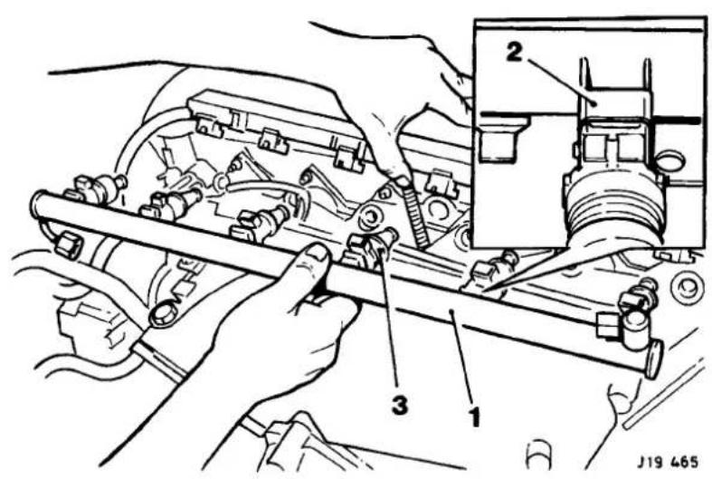
Fig. 1
■ Fit blanking plugs to manifold.
- Drain the residual fuel from the fuel rail into a suitable drain tin.
■Remove the injector retaining clips(2 Fig.1).
■Remove injectors (3Fig. 1).
■ Disconnect vacuum hose from regulator.
■Remove regulator mounting bracket.
■ Undo fuel rail to regulator union nut.
■ Remove regulator assembly.
Refit in the reverse order of the removal procedure.

5.1.4 FUEL RAIL / PRESSURE REGULATOR VALVE/ INJECTORS(NORMALLY ASPIRATED ENGINE), RENEW
SRO 19.60.13
SRO 19.45.11
SRO 18.10.01 INJECTORS
SRO 18.10.02INJECTORS (VEHICLE SET)

Fig. 1
Remove
■ Reposition top edge of trunk front liner for access.
■ Disconnect multi-plug from evaporative loss flange inset (Fig.1).
■ Switch ignition on.
■ Crank engine to depressurize fuel system.
■ Switch ignition off.
■ Disconnect battery, see Section 15.
■ Disconnect earth lead eyelet(1 Fig.1) from inlet manifold stud.
■ Disconnect engine harness to oxygen sensor leads multi-plug.
- Disconnect engine harness to starter motor solenoid link lead multi – plug.
■ Undo fuel injector multi-plug cover fixings (2 Fig.1).
■ Disconnect cover from injectors (3Fig.1).
■ Undo fuel rail to feed pipe union nut (4 Fig.1).


■ Repositionfuel feed pipe from fuel rail union and fit blanking plugs to rail and pipe.
■ Undo and remove regulator mounting bracket to inlet manifold bracket securing bolt (5 Fig.1).
■ Undo fuel rail to regulator union nut.
■ Reposition regulator from fuel rail union and fit blanking plugs.

Fig. 1
■ Undo and remove fuel rail securing bolts.
■ Remove fuel rail assembly(1 Fig.1) from manifold.
■ Fit blanking plugs to manifold.
- Drain the residual fuel from the fuel rail into a suitable drain tin.
- Remove the injector retaining clips(2 Fig.1).
■ Remove injectors (3 Fig.1).
■ Disconnect vacuum hose from regulator.
■ Remove regulator mounting bracket.
■ Undo fuel rail to regulator union nut.
■ Remove regulator assembly.
Refit in the reverse order of the removal procedure.
5.1.5 PURGE CONTROL VALVE (ALL MODELS), RENEW
SRO 17.15.30
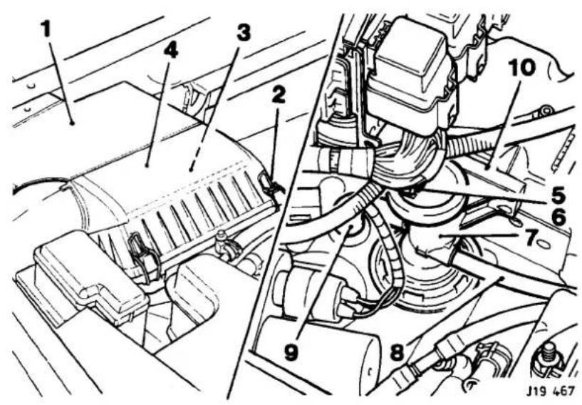
Fig. 1
Remove
■ Remove blanking cover(1 Fig.1).
■ Release air cleaner cover retaining clips (2 Fig.1).
■ Remove filter element (3Fig.1).
■ Remove filter cover(4 Fig.1) from inner wing grommet.
■ Disconnect hose (8Fig.1) from purge valve.
■ Disconnect elbow (9 Fig.1) from front of purge valve.
- Remove purge valve from mounting bracket (10 Fig.1).
■ Depress retaining clip(5 Fig.1) and disconnect connector(6 Fig.1) from purge valve(7 Fig.1).
Refit in the reverse order of the removal procedure.

5.1


5.1.6 THROTTLEASSEMBLY (SUPERCHARGED), RENEW
SRO 18.30.17 THROTTLE POTENTIOMETER
SRO 19.70.07 THROTTLE HOUSING GASKET
SRO 19.70.04 THROTTLE HOUSING
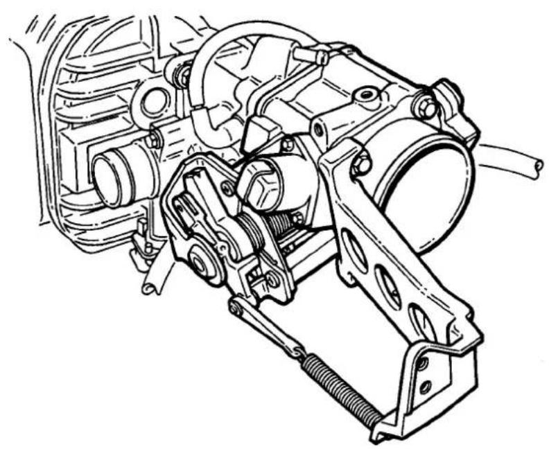
Fig. 1
5.1
Remove
■ Disconnect battery.
■ Remove the intercooler intake elbow.
■ Raise vehicle on a four-post ramp.
■ Remove the rear air duct to throttle body connecting hose.
■ Removethe oil filter cartridge and gasket.
- Undo and remove bolts securingEGR supply pipe to manifold.
- Remove EGR supply pipe gasket.
- Reposition EGR sensor harness multi-plug from mounting bracket.
■ Release throttle outer cable abutment from abutment bracket.
■ Disconnect throttle inner cable from throttle linkage.
■ Remove speed control speed control bracket to throttle lever clevis pin and pin circlip.
■ Disconnect and remove return spring.
■ Disconnect speed control actuator vacuum hose.
■ Release cooling system pressure by slowly undoing the tank cap.
- Tighten cap after pressure release.
■ Remove abutment bracket assembly.
- Disconnect idle speed actuator harness multi-plug.
■ Disconnect throttle potentiometer harness multi -plug.
■ Fit pipe clamps to throttle housing cooling hoses and disconnect hoses from throttle housing.

■ Remove throttle housing.
■ Remove throttle potentiometer.
■ Remove screws securing idle speed actuator to throttle housing.
■ Remove and discard gasket.
■ Remove spacer and undo bolt securing throttle lever assembly to throttle housing.
■ Remove butterfly outer bush, spring and inner bush.
Refit in the reverse order of the removal procedure.
5.1.7 IDLE SPEED CONTROL VALVE / GASKETS (SUPERCHARGED), RENEW
SRO 18.30.74 IDLE SPEED CONTROL VALVE
SRO 18.30.77 IDLE SPEED CONTROL VALVE GASKET
Remove
■ Remove the throttle housing and gasket.
■ Undo and remove bolt securing idle speed control valve.
■ Remove valve.
■ Remove gasket.

Refit in the reverse order of the removal procedure.
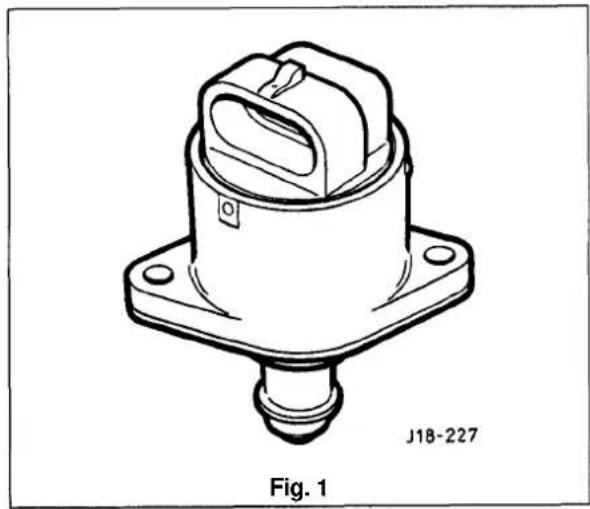
5.1


5.1.8 IDLE SPEED CONTROL VALVE/ GASKETS (NORMALLY ASPIRATED), RENEW
SRO 18.30.74 IDLE SPEED CONTROL VALVE
SRO 18.30.77 IDLE SPEED CONTROL VALVE GASKET
Remove
■ Disconnect battery.
■ Remove the intake elbow to throttle housing hose.
■ Disconnect idle speed control valve multi-plug.
■ Disconnect throttle potentiometer multi-plug.
■ Remove clevis pin circlip.
■ Reposition link arm from quadrant.
■ Disconnect kick down cable (where fitted) from quadrant.
- Open throttle fully and disconnect inner cable from quadrant.
■ Carefully release throttle against stop.
Fit pipe clamps to throttle body heater feed and return hose.
- Disconnect feed hose from throttle body stub pipe.
■ Remove throttle body assembly from inlet manifold.
■ Remove idle speed control valve from throttle body.
■ Remove gasket.
■ Retrieve distance piece from throttle body recess.

Refit in the reverse order of the removal procedure.

5.1.9 FUEL CUT OFF INERTIA SWITCH (ALL MODELS), RENEW
SRO 18.30.35
Remove
- Disconnect battery.
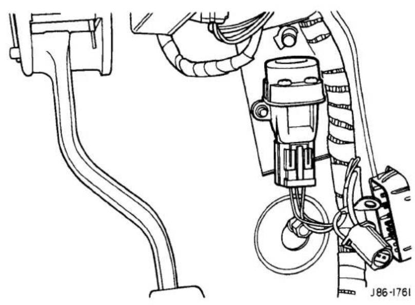
Fin. 1
■ Remove the 'A' post lower trim pad.
- Remove the EMS control module, see Section 15.
- Disconnect vehicle harness through panel connector.
- Disconnect inertia switch multi-plug (Fig. 1).
- Remove switch.


Refit in the reverse order of the removal procedure.

SECTION CONTENTS
| Sub-Section | Title | SRO | Page |
| i | Preliminary Pages | i | |
| 5.2.1 | Fuel System Layout | 1 | |
| 5.2.2 | General Description | 3 | |
| 5.2.3 | Fuel.Rail / Pressure Regulator / Injectors, Renew | 18.10.01 | |
| 18.10.02 | |||
| 18.10.04 | |||
| 18.10.05 | |||
| 19.45.11 | |||
| 19.60.13 | 5 | ||
| 5.2.4 | Purge Control Valve, Renew | 17.15.42 | |
| 17.15.43 | |||
| 17.15.44 | 8 | ||
| 5.2.5 | Idle Speed ControlValve / Gaskets, Renew | 18.30.72 | |
| 18.30.73 | |||
| 18.30.74 | |||
| 18.30.75 | |||
| 18.30.76 | 9 | ||
| 5.2.6 | FuelCut-off Inertia Switch, Renew | 18.30.35 | 9 |


5.2.1 FUEL SYSTEM LAYOUT

The above schematic illustration (Fig1), shows the part and component layout of the fuel system and is to be read with the table on Page 2.
Key to Fig.1, Fuel System V12, page 1
| SRO | Component / parts | Location | Number |
| 19.55.13 | Fuel filler assembly | Rear deck area | 1 |
| 19.55.01 | Fuel tank | Behind rear bulkhead | 2 |
| 19.45.08 | Fuel pumps | Inside fuel tank | 3 |
| Fuel pump filter | Inside fuel tank 4 | ||
| 19.40.97 | Fuel feed line | Fuel pump to fuel filter | 5 |
| 19.25.02 | Fuel filter | Above rear axle assembly 6 | |
| 19.40.60 | Fuel feed line | Fuel filter to fuel rail | 7 |
| 19.60.13 | Fuel rail | Inlet manifold | 8 |
| 18.10.02 | Fuel injectors | Inlet manifold/ fuel rail | 9 |
| 19.45.11 | Fuel regulator valve | Mounted on the fuel rail | 10 |
| 19.40.85 | Fuel return line | Fuel regulator to fuel tank | 11 |
| Emission vent line | Fuel tank to tank pressure control (Rochester) valve | 12 | |
| 17.15.41 | Tank pressure control (Rochester) valve | Connected between emission vent lines as shown on schematic | 13 |
| Emission vent line | Rochester valve to primary carbon canister | 14 | |
| 17.15.13 | |||
| 17.15.13 | Primary carbon canister | Left side of vehicle, in front of the rear axle | 15 |
| Emission vent line | Primary carbon canister to purge valve | 16 | |
| 17.50.30 | Purge valve | Below the left head lamp module | 17 |
| Emission vent line | Primary carbon canister to atmosphere | 18 |
5.2.2 GENERAL DESCRIPTION
WARNING: WORKING ON THE FUELSYSTEM RESULTS IN FUEL AND FUEL VAPOUR BEING PRESENT IN THE ATMOSPHERE.FUEL VAPOUR IS EXTREMELYFLAMMABLE, HENCEGREATCARE MUSTBETAKENWHILST WORKING ON THE FUELSYSTEM. ADHERE STRICTLY TO THE FOLLOWING PRECAUTIONS:
DO NOT SMOKE IN THE WORK AREA.
DISPLAY'NO SMOKING' SIGNS AROUND THE AREA.
ENSURE THAT A CO₂ FIRE EXTINGUISHER IS CLOSE AT HAND.
ENSURE THAT DRY SAND IS AVAILABLE TO SOAK UP ANY FUEL SPILLAGE.
EMPTY FUEL USING SUITABLE FIRE PROOF EQUIPMENT INTO AN AUTHORIZED EXPLOSION PROOF CONTAINER.
DO NOT EMPTY FUEL INTO A PIT.
ENSURE THAT WORKING AREA IS WELL VENTILATED.
ENSURE THAT ANY WORK ON THE FUEL SYSTEM IS ONLY CARRIED OUT BY EXPERIENCED AND WELL QUALIFIED MAINTENANCE PERSONNEL.
5.2
The fuel filler assembly, supplied complete with serviceable lid, hinge and hinge spring, is fixed to the Body-in-White (BIW) decking panel by two M5 nuts. Additional parts of the assembly comprise a adjustable rubber buffer, a snap-in striker and the fuel cap stowage magnet.
The fuel bowl, retained around the filler neck by a clip, containing a drain tube filter located over the mating drain tube, is rubber moulded onto a steel armature and fitted to the BIW decking panel. by five M5 nuts.
The fuel lid latching assembly fitted to the metal armature of the fuel bowl by an M5 nut, includes the locking pin and the operating actuator.
The actuator operates from the central locking system driven by the Security and Locking Control Module (SLCM).
The fuel tank, mounted across the vehicle behind the passenger compartment rear bulkhead, is held in position by two retaining straps, tightened by two M5 fixing arrangements.
V12 engined vehicles are equipped with two fuel pumps located inside the tank. They are regenerative turbine pumps supplied by Nippon Denso. Nominal operating pressure is 3 bar above the manifold depression and pump delivery is 90 litres/hour minimum at 13.2 volts, 3 bar outlet pressure. The pump draws a nominal current of 7 amperes at 13 volts, 3 bar outlet pressure, ambient temperatures. Built into the pump assembly is a over-pressure relief valve which blows at 4.5 - 8.5 bar.
Fuel is drawn by the pumps from the fuel tank and is then supplied to the fuel rail via a 70 micron filter and the fuel feed line connected in series by fuel filter.
The amount of fuel being injected into the engine is controlled by the fuel injectors combined with the engine control module (ECM).
Any excessive fuel flowing through the system, is returned to the fuel tank via the fuel regulator valve mounted on the fuel rail, the fuel return line and the check valve also located inside the tank.
The two filters prevent contaminants from entering the fuel rail and possible damage to the fuel injectors, the engine, the pump and underfloor filter.
The second fuel pump is controlled by the engine control module(ECM) and works of a mapped fuel map. The pumps 'switch on' time depends on the fuel requirement which is depending on the engine load.
The fuel lines are made up of an assembly, combining steel underfloor pipes and flexible conductive anti-permeation tubing. In order to perform speedy remove and refit operations, the underfloor steel lines are linked through the engine bay bulkhead to the flexible tubing, leading to the fuel rail and the fuel regulator by using positive sealing, quick fit type connectors. The same type connectors, are used to connect the fuel feed and return line to the fuel tank.
Connectors used inside the engine bay, are of different sizes to correspond with the difference in pipe diameter, whereas the connectors for the feed and return lines at the fuel tank are the same size.
Except for the return line connector at the fuel tank, two release tools, one for each size of connector, are required to release all remaining connectors.


The connectors are released by pushing the tool into the female half of the connector and at the same time disengaging the latches.
Viton hosing surrounds the tubing, thus preventing any potential damage from fire and other matters.
The conductive anti-permeation tubing does not return to its original shape after being deformed. Therefore do not clamp (eg. for sealing purposes prior to disconnection of tubes) as this damages the fuel pipes.
The evaporative loss control system, prevents unprocessed vapour emitted from the fuel tank from entering the atmosphere.
The tank pressure control (Rochester) valve is installed between the fuel tank and the carbon canister. It is normally closed, but open during engine operation, venting the vapours from the fuel tank to the carbon canister.
The purge valve is controlled by the engine control module (ECM) and is linked to the carbon canister.

Fig. 1 Quick-fit Connector and Release Tool
5.2.3 FUEL RAIL / PRESSURE REGULATOR VALVE / INJECTORS, RENEW
SRO 19.60.13 FUEL RAIL
SRO 19.45.11 REGULATOR VALVE
SRO 18.10.01 INJECTORS
SRO 18.10.02 INJECTORS (VEHICLE SET)
SRO 18.10.04 INJECTOR - LEFT HAND BANK
SRO 18.10.05 INJECTOR - RIGHT HAND BANK

Remove
■ Reposition top edge of trunk front liner.
- Disconnect multi-plug from evaporative loss flange inset (Fig.1).
■ Switch ignition on.
- Crank engine to depressurize fuel system.
■ Switch ignition off.
- Disconnect battery see Section 15.
■ Remove engine cover, See section 3.2.
■ Remove engine cover 1/4 turn fastener receptacles (1 Fig.1) from fuel rail (2 Fig.1).
■ Undo fuel feed hose to fuel rail union nut (3 Fig.1).
■ Reposition fuel feed hose (4 Fig.1) from fuel rail.
- Undo fuel return hose to fuel pressure regulator union nut (5 Fig.1).
- Reposition fuel return hose (6 Fig.1) from fuel pressure regulator (7 Fig.1).


- Disconnect vacuum hose (1 Fig. 1) from cruise control actuator (2 Fig. 1).
■ Disconnect vacuum hose (3Fig.1) from fuel pressure regulator.
■ Disconnect throttle control rods from throttle pulley assembly ball pins (4 Fig.1).
■ Reposition throttle control rods to inner wings.
■ Disconnect cruise control rod from throttle pulley assembly ball pin (5 Fig.1).
■ Undo and remove bolts securing fuel rail.
■ Reposition cruise control rod below throttle pulley assembly.
■ Remove cruise control actuator/ bracket assembly and fixings(6 Fig.1).
■ Disconnect injector harness plugs (7 Fig.1). - Disconnect throttle potentiometer multi-plug (8Fig.1)
■ Remove throttle pulley bracket assembly and fixings (9 Fig.1)
■ Remove injector harness plastic clips (10 Fig.1) from fuel rail.
■ Remove fuel rail/ injector assembly (11 Fig.1).

J19 L76
Fig. 1
■ Remove injector to fuel rail retaining clips (1 Fig.1).
■ Remove injector (2 Fig.1).
■ Remove fuel regulator retaining plate and fixings (3 Fig.1).
■ Remove fuel regulator (4 Fig. 1).
■ Remove and discard 'O' ring seals.
Refit in the reverse order of the removal procedure.
5.2.4 PURGE CONTROL VALVE, RENEW
SRO 17.15.42 'A' BANK
SRO 17.15.43 'B'BANK
SRO 17.15.44 VEHICLE SET

Fig. 1
Remove
■ Remove the left and headlamp relay cover (1 Fig.1), see Section 15.
■ Remove the left and air cleaner element (2Fig.1).
■ Remove the right and air cleaner assembly (3 Fig.1).
■ Remove air box mounting bracket (4Fig.1).
■ Disconnect 'A' bank purge valve multi-plug(5 Fig.1).
■ Release securing clip (Fig.1).
■ Disconnect all hose(7 Fig.1) from valve.
■ Remove valv(8Fig.1).
Refit the purge valve in the reverse order of the removal procedure.

5.2.5 IDLE SPEED CONTROL VALVE/ GASKETS, RENEW
SRO 18.30.74 VEHICLE SET
SRO 18.30.73 VALVE-RIGHT HAND
SRO 18.30.72 VALVE - LEFT HAND
■ Disconnect battery.
- Drain coolant from radiator, see Section 4.2.
■ Disconnect idle speed control valve multi-plug.
- Disconnect all hoses linked to the idle speed control valve.
■ Remove valve.
■ Remove gasket.
Refit in the reverse order of the removal procedure.


5.2.6 FUEL CUT -OFF INERTIA SWITCH, RENEW
SRO 18.30.35
Remove
■ Disconnect battery.
■ Remove the 'A' post lower trim pad.
- Remove the EMS control module, see Section 15.
- Disconnect vehicle harness through-panel connector.
■ Disconnect inertia switch multi-plug (Fig. 2).
- Remove switch.
Refit in the reverse order of the removal procedure.
5.2

Fig. 2


SECTION CON TENTS
| Sub-Section | Title | SRO | Page |
| i | Preliminary Page | i | |
| 6.1.1 | Exhaust System. General Description | 1 | |
| 6.1.2 | Diagnosis & Testing | 5 | |
| 6.1.2.1 | Symptom Chart | 5 | |
| 6.1.2.2 | TestA. Exhaust Leakage or Noise | 5 | |
| 6.1.2.3 | TestB, Restriction in Exhaust System | 6 |

6.1


6.1.1 EXHAUST SYSTEM, GENERAL DESCRIPTION
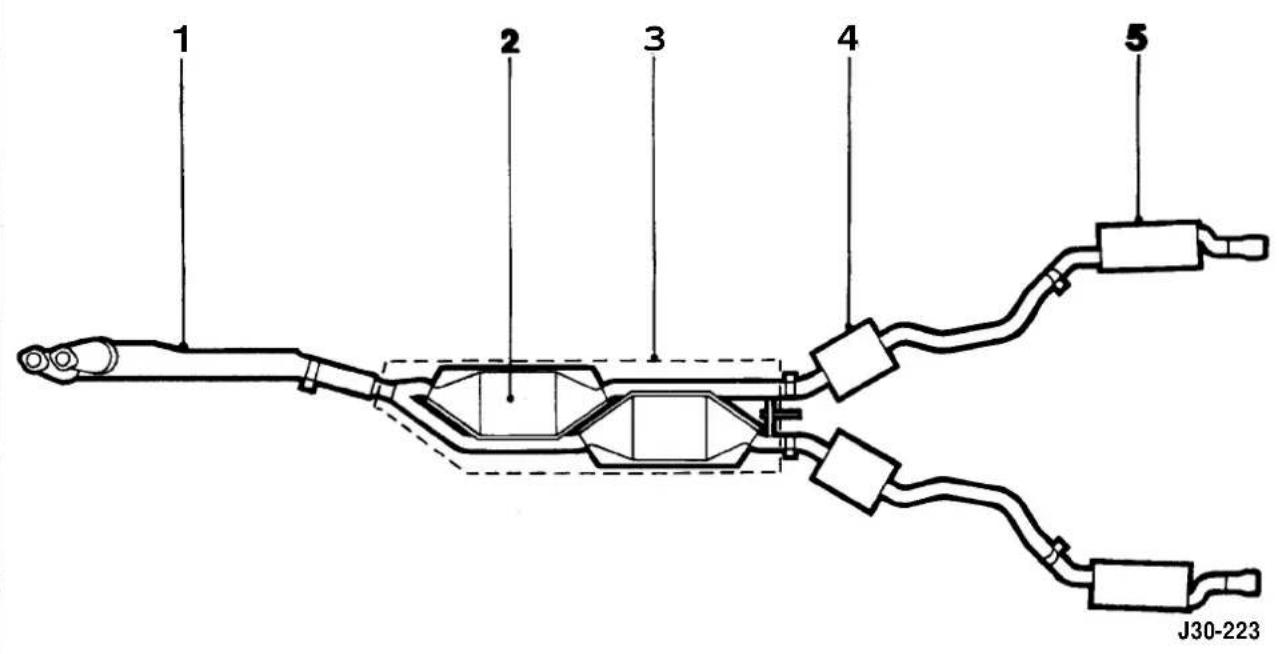
Fig. 1 Plan View, Exhaust System (AJ16 Normally Aspirated)
This section covers the various exhaust systems fitted to AJ16 engined vehicles.
Always refer to the Parts Catalog for parts usage and interchangeability before replacing a component part of the exhaust system.
The low-loss catalytic converter exhaust system for the AJ16 normally aspirated engine comprises of a catalyst/downpipe assembly (1 Fig.1), a underfloor catalytic converter assembly
(2 Fig. 1) complete with heat shield (3 Fig. 1), an intermediate muffler section (4 Fig. 1) and a rear muffler section (5 Fig. 1).
On non-catalytic converter systems the downpipe/catalyst assembly is fitted with conventional twin branch downpipes, hence there are no oxygen sensors or gas temperature sensors.
Conventional mufflers are fitted in place of the underfloor converters.
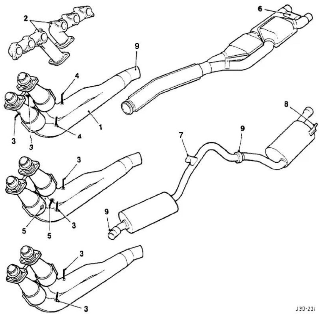
Fig. 1 Components of the Exhaust System (AJ16 Normally aspirated)
Heated oxygensensors are fitted to the downpipe assembly (1 Fig. 1) which is connected to the manifold (2 Fig. 1). There are two sensors for the ROW and Japan (3 Fig. 1) and two additional sensors (4 Fig. 1) for NAS markets.
The sensors are located upstream and downstream of catalytic converters.
Apart from two heated oxygen sensors, the exhaust system for vehicles destined for the Japanese market are also fitted with two exhaust gas temperature sensors (5 Fig.1).
The exhaust system is held in a predetermined position by a fixing arrangement to the manifold by exhaust centre mountings (6Fig.1), by rear axis mountings (7Fig.1), and tail pipe mountings (8Fig.1).
Clamps (9 Fig.1) used on each slip joint are welded to the pipes and tightened to a higher torque setting than non-welded clamps.
The exhaust system must be free of leaks, binding, grounding and excessive vibrations. These conditions are usually caused by loose, broken, or misaligned clamps, shields, brackets, or pipes. Should any of these conditions exist, check the exhaust system components and alignment. Adjust and renew if necessary. Do not attempt to service brackets, clamps and insulators.
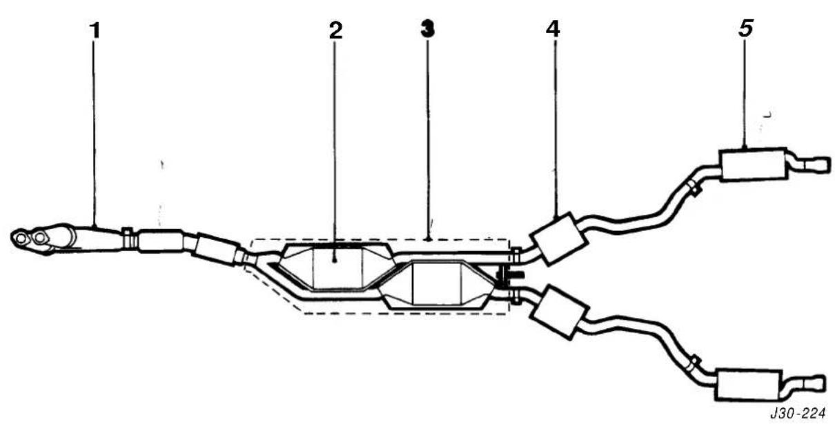
Fig. 1 Plan View (AJ16 Supercharged)
The only visible difference between the normally aspirated engine's exhaust system and the supercharged version (Fig.1) is that the downpipe for the supercharged engine (Fig.1 and next page) is slightly shorter. The remove & refit procedures are the same as for the AJ16 normally aspirated.
6.1
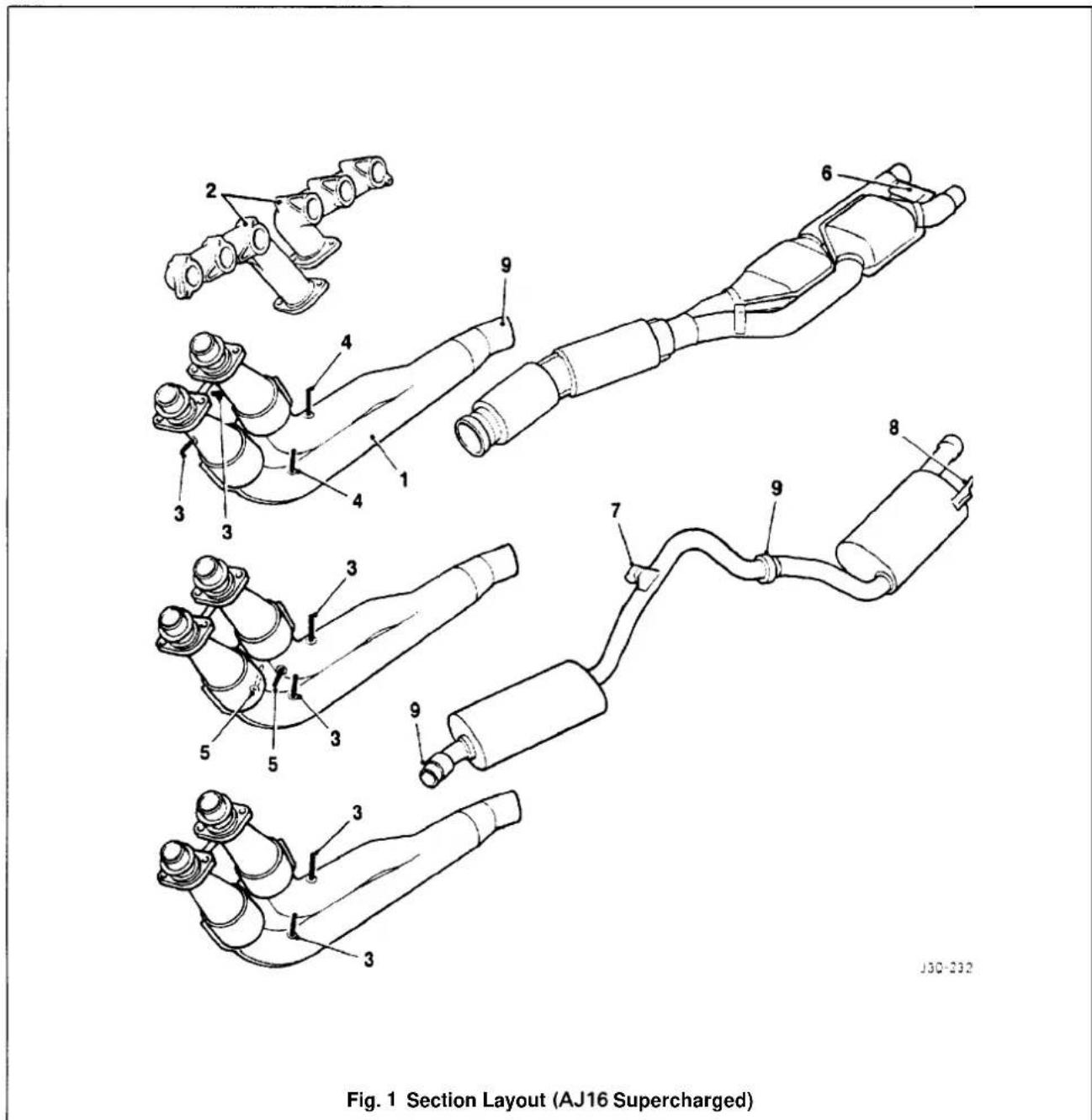
6.1.2 DIAGNOSIS AND TESTING
WARNING: THE NORMAL OPERATING TEMPERATURE OF THE EXHAUST SYSTEM IS VERY HIGH. NEVER ATTEMPT TO SERVICE ANY PART OF THE SYSTEM UNTIL IT HAS COOLED. EXHAUST GASES CONTAIN CARBON MONOXIDE WHICH CAN BE HARMFUL TO HEALTH AND ARE POTENTIALLY LETHAL. LEAKS MUST BE REPAIRED IMMEDIATELY. NEVER OPERATE THE ENGINE IN ENCLOSED AREAS.
External leaks in the exhaust system are often accompanied by noises and exhaust fumes, therefore a visual inspection usually detects the location of the leak. When checking for exhaust leakage or noise, inspect the entire system for burned-out holes, loose or corroded clamps, muffler or exhaust inlet pipe.
Examine the under body for greyish-white or black exhaust soot which indicates the exhaust leakage at that point.
The effect of a small leak can be magnified by holding a rag over the tailpipe outlet while listening to the leak.
If this is carried out, ensure that gases are not inhaled -see WARNING.
When testing for a rattle or vibration condition it is helpful to use a rubber mallet. Tap on the exhaust components to simulate the bouncing action of the exhaust while watching for exhaust-to-body / chassis contact.
Also look for loose and rusted flange connections, loose or damaged exhaust shields or clamp and loose or broken exhaust outlet pipe brackets.
6.1.2.1 Symptom Chart
| Condition | Possible Cause | Action |
| Noises and exhaust fumes Exhaust | Mispalined exhaust. Loose clamps or fasteners. Restricted exhaust system. | Refer to Test Step 1A.Go to Test Step 1B, Restricted exhaust system test. |
| Engine lacking power Ignition | system.Electronic engine controls.Fuel System.Restricted exhaust system. | Go to Test Step 1B |
6.1.2.2 Test A, Exhaust Leakage or Noise
| Test Step | Result | Action |
| Step1A Clamps and Brackets | yes | Go to Step2A |
| Check for broken or loose clamps and/or exhaust outlet pipe frame brackets.Are clamps and exhaust outlet pipe frame brackets OK? | no | Service and renew as necessary.Restart engine.If noise still existsgo to Step2 |
| Step 2A System Components | yes | Go to step3ARenew exhaust outlet pipe frame brackets, exhaust inlet pipe and/ or muffler as necessary.If noise still persists, go to Step3 |
| Check catalytic converters, muffler.Are system components OK? | no | |
| Step 3A Exhaust Manifold | yes | Go to Test Step1B Restricted exhaust system test.Tighten fasteners or renew exhaust manifold. |
| Inspect exhaust manifold for loose fasteners and cracks.Is exhaust manifold OK? |


6.1.2.3 Test B, Restriction in Exhaust Systems
| Test Step | Result | Action |
| Step 1B Visual Inspection | YesNo | Go to Step 2 BRenew any collapsed exhaust components. Go to Step 2 |
| $ the exhaust system visuallyOK? | ||
| Step2B Vacuum Test | YesNo | Refer to EDMGo to Step 3 |
| Attach a Vacuum Gauge or equivalent to the intake manifold vacuum source.Connect a Tachometer or equivalent.Start engine and gradually increase speed to 2000rpm with transmission in neutral.Is neutral vacuum above 53.8kPa (16 in. Hg)? | ||
| Step 3B Vacuum Test Exhaust Disconnected | YesNo | Go to Test Step 4B |
| Turn engine OFF.Disconnect exhaust system at the exhaust mani-fold.Repeat vacuum test.Is the manifold vacuum above 53.8kPa (16 in. Hg)? | ||
| Step4B Vacuum Test Catalytic Converter(s) on, Mufflers off. | YesNo | Renew muffler andre-test.Renew catalytic converter. |
| Turn engine OFF.Reconnect exhaust system at the exhaust manifold.Disconnect mufflerRepeat vacuum test.Is the manifold vacuum above 53.8kPa (16in. Hg)? |
6.1
SECTION CON TENTS
| Sub-Section | Title | SRO | Page |
| i | Preliminary Page | i | |
| 6.2.7 | General Description | 7 | |
| 6.2.2 | Diagnosis& Testing | 3 |

6.2


6.2.1 GENERAL DESCRIPTION

Fig. 1 Plan View of Exhaust system
'he low-loss catalytic converter exhaust system for the V12 engine comprises catalyst/downpipe assembly with additional secondary catalytic converters (1 Fig.1), a underfloor catalytic converter assembly (2 Fig.1) complete with heat shield (3Fig.1), an intermediate muffler section (4 Fig.1) and a rear muffler section (5 Fig.1).
On non-catalytic converter systems, the downpipe/catalyst assembly is fitted with conventional twin branch down-pipes (6Fig.1), hence there are no oxygen sensors or exhaust gas temperature sensors.
Conventional mufflers are fitted in place of the underfloor converters.


Fig. Components of the Exhaust System
Two heated oxygen sensors are fitted to the downpipe assembly (1 Fig.1) which is connected to the manifold and two on the underfloor catalyticconverter assembly in front of the catalysts. There are two sensors for the ROW and Japan markets (2 Fig.1) and two additional sensors (3Fig.1) for the NAS markets.
The sensors are located on A-bank and B-bank, upstream and downstream of catalytic converters.
Apart from two heated oxygen sensors, the exhaust system for vehicles destined for the Japanese market are also fitted with two gas temperature sensors (4 Fig.1).
The exhaust system is held in a predetermined position bya fixing arrangement to the manifold by exhaust centre mountings (5 Fig.1), by rear axis mountings (6 Fig.1), and tail pipe mountings(7 Fig.1).
Clamps (8Fig.1) used on each slip joint are welded to the pipes and tightened to a higher torque setting than non-welded clamps.

The exhaust system must be free of leaks, binding, grounding and excessive vibrations. These conditions are usually caused by loose, broken, or misaligned clamps, shields, brackets, or pipes.
Should any of the above mentioned conditions exist, check the exhaust system components and alignment.
Adjust and renew if necessary. Do not attempt to service brackets clamps and insulators.
6.2.2 DIAGNOSIS AND TESTING
The standard exhaust system Diagnosis and Testing procedures are given in Section 6.1 (Exhaust System (AJ16)).

6.2


SECTION CONTENTS
| Sub-Section Title | SRO | Page |
| i to iv | Preliminary Pages | i to iii |
| 7.1.1 | Manual Transmission. Description | 1 |
| 7.1.2 | Manual Transmission Assembly, Renew | 37.20.0 1 |
| 7.1.3 | Front Oil Seal, Renew | 37.23.06 |
| 7.1.4 | Rear Oil Seal, Renew | 37.23.01 |
| 7.1.5 | Gearshift Lever, Renew | 37.16.04 |
| 7.1.6 | Gearshift Lever Draught Excluder, Renew | 37.16.05 |
| 7.1.7 | Gearshift Lever Knob. Renew | 37.16.11 |
| 7.1.8 | Gearshift Lever/ Remote Control Assembly, Renew | 37.16.20 |
| 7.1.9 | Gear Selector Shaft - Rear, Overhaul | 37.16.4 1 |
| 7.1.10 | Reverse Lamp Switch. Renew | 37.27.01 |
| 7.1.11 | Layshaft Front Seal. Renew | 37.23.07 |
| 7.1.12 | Clutch. Description | 10 |
| 7.1.13 | Clutch. Fault Diagnosis | 11 |
| 7.1.14 | Clutch Assembly, Renew | 33.10.01 |
| 7.1.15 | Clutch Master Cylinder, Renew | 33.20.01 |
| 7.1.16 | Clutch Slave Cylinder, Renew | 33.35.01 |
| 7.1.17 | Clutch Slave Cylinder, Overhaul | 33.35.07 |
| 7.1.18 | Clutch Hydraulic System. Bleed | 33.15.01 |


I. SERVICE TOOLS & EQUIPMENT
| Illustration | Jaguar Number | Description Notes | ||
 | 18G 1465 | Engine lifting brackets | ||
| Engine support beamsupport beam | ||||
| MS 53C | ||||
II. TORQUE TIGHTENING SPECIFICATIONS
| Fixing Tightening Torque | (Nm) |
| Bell housing to adaptor plate | 49 - 54 |
| Bleed nipple to slave cylinder | 8 - 10 |
| Center bearing to body | 22 - 28 |
| Center bearing to mounting plate | 22 - 24 |
| Clutch cover to flywheel | 23 - 27 |
| Clutch damper to mounting bracket | 7 - 10 |
| Flywheel to crankshaft | 95 - 105 |
| Front cover to transmission | 23 - 27 |
| Front pipe to intermediate pipe | 15 - 18 |
| Gearshift leverhousing to transmission | 23 - 27 |
| Hydraulic pipes to clutch damper | 16 - 22 |
| Hydraulic pipe to master cylinder | 16 - 22 |
| Hydraulic pipe to slave cylinder | 16 - 22 |
| Master cylinder to housing | 15 - 21 |
| Pedal housing to body | 24 - 30 |
| Pedal steady bracket to housing | 18 - 20 |
| Drive (propeller) shaft center mounting to body | 22 - 28 |
| Drive (propeller) shaft to transmission | 95 - 105 |
| Slave cylinder to bell housing | 15 - 21 |
III.
| Molykote FB 180 grease | Withdrawal arm pivots/ Gearshift lever ball | |
| Brake (clutch) fluid – minimum DOT 4 | Clutch hydraulic system | |
| Dexron IID | Transmission oil | also used in ZF automatic transmissions |
| Loctite 573 | Front cover securing bolts | |
| Tivoli Kay Adhesives No. 5696 | Exhaust sealer |
IV. SERVICE DATA
| Application | Specification |
| Material removal to clean up clutch face | Up to 1mm maximum |
7.1.1 MANUAL TRANSMISSION, DESCRIPTION
The Getrag 290 5-speed manual transmission (Fig.1), fitted to this vehicle incorporates synchromesh on all forward gears.
Gear selection is by a centrally mounted lever, connected to the transmission selector shaft via a pivoting joint.
All gears are engaged by a single selector shaft operating three rods which move the selector forks.
The drive pinion is supported at the rear by a duplex ball bearing situated in the front casing and at the front, a spigot engages in a needle roller bearing in the flywheel.
The mainshaft is supported at the front by a caged roller bearing situated in the drive pinion counterbore;inthe centre by a roller bearing supported by the intermediate casing and at the rear by a duplex bearing in the transmission rear casing.
Each of the forward speed mainshaft gears incorporates an integral synchromesh mechanism, with the clutch hubs splined to the mainshaft and situated between each pair of gears.
The countershaft is supported at the front by a roller bearing situated in the front casing; in the centre by a roller bearing in the intermediate casing and at the rear by a roller bearing situated in the tail housing.
The reverse idler gear is supported by two caged roller bearings, is in constant mesh and is situated on a stationary shaft.
Longitudinal location of the idler gear is controlled by a spacer abutting the shaft.

J37-099
Fig. 1 The Getrag 290 Transmission


7.1.2 MANUAL TRANSMISSIONASSEMBLY, RENEW
SRO 37.20.01
■ Disconnect the battery.
■ Remove inlet manifold rear securing nuts.
■ Remove injector harness mounting bracket.
■ Fit lifting bracket 18G 1465 and secure with the nuts.
■Fit Service ToolMS 53B (Fig. 1) across the wing channels and align to rear lifting bracket.
• Fit and engage retaining hook.
■ Tighten hook nut to take weight of engine.
■ Disconnect lambda sensor block connectors.
■ Remove the exhaust front pipe to the intermediate pipe securing nut/ bolt.
■ Remove the front pipe to manifold securing nuts and remove the front pipe assembly.
■ Carefully ease exhaust system down for access.
■ Remove the drive (propeller) shaft assembly, see Section 9, SRO 47.15.01.
■ Fit blanking plug to rear of transmission.
■ Remove clutch slave cylinder complete with push rod from bell housing and secure clear.
- Disconnect transmission switch multi-way connector and secure clear.
■ Place jack in position beneath the transmission.
■ Take weight on the jack, and remove rear mounting to body securing bolts.
■ Lower jack and remove rear mounting assembly.
- Remove jack and jacking channel.
■ Remove mounting spring and spring mounting rubber.
■ From above: undo retaining hook nut to lower rear of transmission (do not allow engine to foul steering rack).
■ From below: removes selector shaft yoke securing nut/bolt (3 Fig. 2).
■ Disconnect selector shaft yoke from lower gearshift lever and remove wavy washer.
■ Remove gear selector remote control securing bolts (1 Fig. 2).
■ Remove mounting rubbers and washers(2 Fig. 2).
■ Reposition remote control assembly for access.
■ Remove transmission – to-engine adaptor plate securing bolts (1 Fig. 3).
Note: Leave two opposing bolts in for safety.
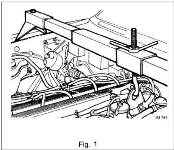

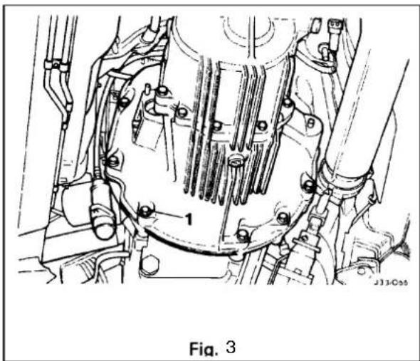
7.1

■ Remove front clamp from unit lift.
■ Raise / lower unit with jack, no stands.
■ Traverse lift under ramp and take weight of transmission.
■Adjust jacking platform angles to suit transmission.
■ Adjust side and rear clamps to suit transmission and tighten clamp wing nuts.
■ Fit the safety chain assembly to left hand arm of lift, and secure with peg.
• Pass safety chain over transmission and engage in front arm of lift. Tighten the safety chain adjuster.
■ Remove remaining transmission to adaptor plate securing bolts and carefully lower transmission from engine.
■ Removetransmission from ramp area.
■ Remove clutch release bearing assembly from release lever.
■ Remove clutch release lever retaining clip and remove lever.
■ Remove release lever pivot pin.
- Remove transmission switch.
■ Remove rear mounting spring retainer securing nut.
- Remove rear mounting spring retainer and remove rear mounting assembly.
■ Reposition selector shaft pin cover.
■ Remove selector shaft yoke to selector shaft retaining pin and remove the yoke.
■ Remove slave cylinder securing studs.
■ Remove the transmission from the unit lift.
■ Removetransmission drain plug and allow to drain, refit the drain plug.
• Fit new transmission to unitlift.
- Fill transmission with oil and refit the level plug.
■ Clean components and mating faces.
■ Fit the slave cylinder mounting studs.
■ Lubricate the selector output shaft.
■ Fit selector shaft yoke(3 Fig. 1) to selector shaft and secure with retaining pin (2 Fig. 1).
- Reposition the retaining cover (1 Fig. 1) over the selector shaft yoke retaining pin.
■ Fit the transmission rear mounting assembly and secure with bolt.
■ Fit reverse lamp switch.
■ Lubricate the clutch release lever.
■ Fit and align lever to transmission and engage onto pivot pin.
- Fit and fully seat lever to pivot retaining clip.
■ Lubricate release bearing housing.
■ Fit and fully seat bearing assembly to lever.
■Select third gear.
■ Move transmission to vehicle and raise into position.
- Insert transmission input shaft into clutch and fully seat transmission against adaptor plate, ensuring that transmission is in line as it is fitted and seated to the plate.


- Fit and tighten transmission to adaptor plate securing bolts (1 Fig. 1).
■ Slacken chain adjuster.
■ Release securing peg from adjuster.
■ Displace securing chain from the unit lift.
■ Slacken clamp from wing nuts.
■ Release clamps from transmission.
■ Lower lift and traverse aside.
■ Refit front clamp to unitlift.
■ Connect transmission switch and fit multi-way connector into securing clip.
■ Clean and lubricate clutch slave cylinder push rod and fit to slave cylinder.
■ Fit slave cylinder to mounting studs and secure with nuts. - Fit and seat remote control mounting rubbers and spacers.
■ Align remote control assembly to transmission.
■ Fit mounting rubber backing washers.
■ Refit remote control mounting and secure with bolts (1 Fig. 2).
■ Fit wavy washer to gearshift lever.
■ Position selector shaft yoke to gearshift lever.
■ Apply lubricant to selector shaft yoke / gearshift lever assembly.
■ Fit and tighten selector shaft yoke to gearshift lever securing nut/ bolt (3 Fig. 2).
■ From above: Tighten MS 53B hook nut to raise trans - mission into position (Fig.3).
■ Position the jack beneath the transmission.
■ Fit spring to rear mounting assembly.
■ Fit upper rubberto mounting spring. - Using a jack, fit and seat the mounting assembly to the body/ transmission.
■ Fit but do not fully tighten mounting securing bolts.
■ Lower and remove jack.
■ Remove jack channel.
■ From above: Fully undo MS 53B hook nut.
■ From below: Final align mounting to transmission/ body.
■ Finaltighten the mounting assembly securing bolts.
■ Clamp the front exhaust pipe in a vice.
■ Remove and discard the front pipe to manifold sealing rings. - Clean the faces.
■ Fit and fully seat new rings to pipe.
■ Remove the front pipe from the vice and align to the manifold.
■ Align retaining rings to the studs and secure with the nuts.

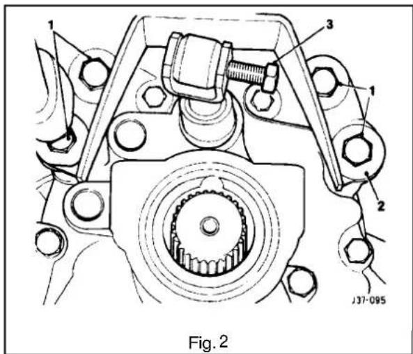


- Fit drive (propeller) shaft to transmission, see Section 9, SRO 47.15.01.
- Clean exhaust joint area, smear with sealant and fit to intermediate pipe.
■ Connect exhaust system to front pipe.
■ Fit and tighten clamp securing nut / bolt. - Reposition lambda sensor harness to allow connection from above.
■ Reconnect lambda sensor block connectors.
■ Remove MS 53B hook and retaining tool.
■ Undo and remove lifting bracket securing nuts.
■ Remove lifting bracket. - Fit injector harness mounting bracket.
- Fit and tighten manifold securing nuts.
- Secure injector harness to mounting bracket.
7.1.3 FRONT OIL SEAL, RENEW
SRO 37.23.06

- Remove the transmission assembly (see Sub-Section 7.1.2), and place it on a bench.
- Place drain tray beneath the transmission assembly.
■ Remove the front securing bolts (1 Fig. 1) and remove the front cover. - Note and remove the shims.
- Remove the oil seal from the assembly.
- Clean the front cover and gasket faces.
- Clean the shims.
■ Lubricate the face of the new seal. - Fit and seat the seal to the assembly.
- Fit the shims to the cover.
■ Apply sealant to the front cover. - Lubricate the seal lip.
- Fit and seat the front cover to the transmission and secure with the bolts.
■ Remove the transmission filler plug. - Fill the transmission to the correct level and refit the filler plug.
- Remove the drain tray.
- Refit the transmission assembly (see Sub-Section 7.1.2).


7.1.4 REAR OIL SEAL, RENEW
SRO 37.23.01
- Remove the drive (propeller) shaft, see Section 9, SRO 47.15.01.
■ Using a suitable oil seal remover, displace and removethe rear oil seal(1 Fig.1).
■ Clean the seal mounting face.
■ Lubricate the seal lip.
■ Fit and seat the seal to the transmission.
■ Refit the drive shaft, see 47.15.01.
7.1.5 GEARSHIFT LEVER, RENEW
SRO 37.16.04
■ Remove and strip down the gear selector remote control assembly as detailed in Sub-section 7.1.8.
■ Rebuild and refit the gear selector remote control assembly (Sub-Section 7.1.8), but fit a new replacement gear-shift lever and discard the original lever.
■ Remove the gearshift lever knob (1 Fig. 2), see Sub-Section 7.1.7.
■ Open the centre console storage compartment.
■ Remove the centre console securing screws, disconnect the block connectors and remove the console.
■ Remove the foam sealing ring.
■ Remove the draught excluder securing screws (2 Fig. 2) and ring(3 Fig. 2) and remove the draught excluder (4 Fig. 2).
■ Fit the new draught excluder over the gearshift lever and secure with the ring(3 Fig. 2) and screws (2-Fig. 2).
■ Refit the foam sealing ring.
- Refit the centre console and reconnect the block connectors and secure with the screws.
- Close the centre console storage compartment.
■ Fit the gearshift lever knob/lock nut and align the knob to its final position.
■ Tighten the lock nut and reposition the gearshift lever gaiter.


7.1
7.1.7 GEARSHIFT LEVER KNOB, RENEW
SRO 37.16.11
- Displace the gearshift lever gaiter for access and slacken the gearshift lever knob lock nut(1 Fig. 1) and remove the gearshift lever knob (2 Fig. 1).
- Fit the new gearshift lever knob and align to its final position.
■ Tighten the lock nut and reposition the gearshift lever gaiter.

7.1.8 GEARSHIFT LEVER/ REMOTECONTROL ASSEMBLY, RENEW
SRO 37.16.20
■ Disconnect the battery.
■ Remove inlet manifold rear securing nuts.
■ Fit lifting bracket 18G 1465 and secure with the nuts.
■ Fit Service Tool MS 538 (Fig. 2) across the wing channels and align to rear lifting bracket.
■ Fit and engage retaining hook.
■ Tighten hook nut to take weight of engine.
■ Select third gear and remove the gearshift lever knob.
■ Disconnect lambda sensor block connectors.
- Remove the exhaust front pipe to the intermediate pipe securing nut/ bolt.
■ Remove the sealing olive.
■ Take the weight of the rear engine mounting using a jack, jack channel and a suitable block.
■ Remove the rear mounting securing bolts.
■ Lower and remove the rear mounting assembly.
■ Carefully ease exhaust system down for access.
■ Remove the drive (propeller) shaft assembly, see Section 9, SRO 47.15.01.
■ From above: undo retaining hook nut to lower rear of transmission (do not allow engine to foul steering rack).
■ From below: slacken but do not remove the selector shaft bolt (3 Fig. 3).
■ Remove the gear selector remote control securing bolts (1 Fig. 1) and reposition for access.
• Finally remove the selector shaft bolt (3 Fig. 3).
■ Remove the gear selector remote control assembly from the selector shaft.
Note: To aid removal, invert the gear selector remote control assembly, i.e. gearshift lever pointing downwards.


■ Ensure that the draught excluder is not displaced from its position.
■ Remove the mounting rubbers and washers (2 Fig. 1).
■ Mount the gear selector remote control assembly (1 Fig. 2) in a vice.
■ Remove the spring ring(2 Fig. 2).
■ Remove the gearshift lever(5 Fig. 2).
■ Remove the spring retainer (3 Fig. 2) and spring (4 Fig. 2) from the gearshift lever.
■ Remove the gearshift lever lower nylon cup (6Fig.2) and upper nylon cup (7Fig.2).
■ Remove the lever housing assembly from the vice.
■ Clean all components thoroughly and examine for wear and damage.
■ Replace worn or damaged components as necessary.
■ Ensure mating faces are clean and grease-free.
■ Mount the gear selector remote control assembly (1 Fig. 2) in a vice.
■ Fit and seat the lower nylon cup (6 Fig. 2).
■ Grease the gearshift lever ball.
■ Fit and seat the upper nylon cup (7 Fig. 2).
■ Fit the spring (4 Fig.2) and spring retainer (3 Fig. 2) to the lever.
■ Fit and seat the gearshift lever
■ Compress the spring(4 Fig. 2).
• Fit and seat the spring ring (2 Fig. 2).
■ Remove the gear selector remote control assembly (1 Fig. 2) from the vice.
- Lubricate the gearshift lever to ease fitment through the draught excluder.
■ Lubricate the lower spacer.
- Position the assembly in its mounting location; enter the gearshift lever into the gaiter.
■ Position the gearshift lever into the selector shaft yoke.
■ Fit but do not tighten the selector shaft bolt (3 Fig. 1).
• Fit the lower LH mounting rubber and washer.
■ Fit the remaining mounting rubbers / washers (2 Fig. 1) and secure with the bolts (1 Fig. 1).
■ Secure the selector shaft bolt (3 Fig. 1).
■ Tighten MS 538 hook nut to raise the transmission into position.
- Using a jack, fit and seat the rear mounting to the transmission/body, ensuring that the spring is seated correctly in the spring pan.
■ Fit but do not fully tighten the mounting securing bolts.
■ Remove the jack and jack channel.
■ Secure the rear mounting bolts.
■ Slacken off MS 538 hook nut.
■ Refit the drive (propeller) shaft assembly, see Section 9, SRO 47.15.01.
■ Remove ServiceTool MS538.
■ Refit the gearshift lever knob.
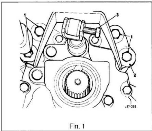
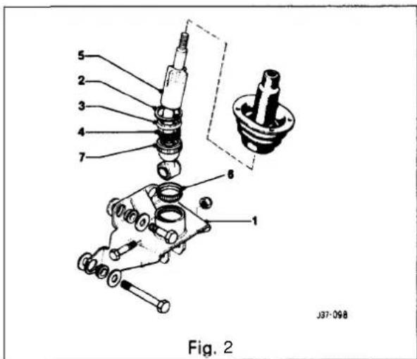
7.1

7.1.9 GEAR SELECTOR SHAFT - REAR, OVERHAUL
SRO 37.16.41
■ Remove the gear selector remote control assembly, see 37.16.20.
- Displace the selector shaft cover(1 Fig. 1).
■ Removethe selector shaft to selector shaft yoke retaining pin (2 Fig. 1), and remove the yoke (3 Fig. 1).
■ Clean all components thoroughly and check for wear and damage.
■ Replace worn or damaged components as necessary.
■ Lubricate and fit the selector shaft yoke to the selector shaft and secure with the retaining pin.
■ Reposition the selector shaft cover.
■ Refit the gear selector remote control assembly, see 37.16.20.

Fig. 1

7.1.10 REVERSE LAMP SWITCH, RENEW
SRO 37.27.01
■ Raise the vehicle on a ramp.
- Note and disconnect reverse lamp switch multi-way connector.
■ Slacken off and remove the switch.
- Clean the mating face.
- Fit a new switch.
■ Connect the multi-way connector.
■ Lower the ramp.
7.1.11 LAYSHAFTFRONT SEAL, RENEW
SRO 37.23.07
- Remove the transmission assembly, see Sub-Section 7.1.2
■ Removethefront oil seal assembly, see Sub-Section 7.1.3.
■ Using suitable oil seal remover tool, remove and discard layshaft plug seal.
■ Clean the transmission face and the front oil seal assembly.
■ Fit and fully seat the new seal to the casing. - Refit the transmission front seal assembly.
■ Refit the transmission.

7.1

7.1.12 CLUTCH, DESCRIPTION
The single-plate, diaphragm -type clutch, is operated by the pushrod of the slave cylinder acting on the clutch lever. The slave cylinder, mounted on the transmission bell housing, is operated hydraulically from the clutch master cylinder through a series of hydraulic pipes.
The piston in the master cylinder is operated by a push rod from the clutch pedal, which is fitted to the bulkhead mounted pedalbox.
The clutch pedal is positioned to the left of the brake pedal.
The engines use a twin-mass flywheel configuration with built-in springs to provide a smooth take-up of drive.
The flywheel is extremely heavy and great care must be taken when lifting it from the vehicle.

Fig. 1 The Clutch Assembly
CAUTION: The hydraulic fluid used in the clutch hydraulicsystem is injurious to car paintwork. Utmost precautions MUST at all times be taken to prevent spillage of fluid. Should fluid be accidentally spilled onto the paintwork, wipe fluid off immediately with a cloth moistened with denatured alcohol (methylated spirits).
7.1.13 CLUTCH FAULT DIAGNOSIS
| Symptom | Possible Cause | Check | Remedy |
| Difficult gear engagement | Hydraulic system defects | Check fluid level in reservoir | Replenish as necessary and bleed system if necessary |
| Check for air in the system | Bleed the system | ||
| Rattling clutch | Operating mechanism faults | Check for defective pedal | Renew return spring if necessary |
| Clutch unit faults | Check for damaged pressure plate | Renew pressure plate | |
| Check splines on clutch driven plate and primary pinion shaft for wear | Renew as necessary clutch plate or primary pinion | ||
| Check clutch driven plate for loose or brokersprings and for warping | Renew driven plate | ||
| Check for wear in the clutch withdrawal mechanism | Renew as necessary | ||
| Check for worn primary pinion bearing | Renew as necessary | ||
| squeaking clutch | Primary pinion bearing fault | Check for seizing on primary shaft or in flywheel | Lubricate or renew as necessary |
| dibrating clutch or clutch judder (often preceded by clutch grab) | Clutch unit faults | Check the clutch driven plate for distortion and damage and for loose or broken torque damper springs | Renew driven plate |
| Check for oil and other foreign matter on the clutch friction linings | Renew driven plate and clear related parts | ||
| Check for incorrectly fitted clutch pressure plate | Dismantle from clutch and refit where applicable | ||
| Check that contact witness on friction linings is evenly distributed | Renew driven plate as necessary | ||
| Defects other than in clutch unit | Check for loose flywheel fixings and flywheel run-out | Tighten to correct torque loading | |
| Check for loose engine mountings | Tighten mounting nuts and bolts | ||
| Check for worn drive (propeller) shaft universaljoints | Renew if necessary | ||
| Check for bent primary pinion shaft | Renew as necessary | ||
| stiff clutch operation | Operating linkage fault | Check for damaged moving parts in operating linkage | Renew as necessary |
| Check for seized linkage, recheck operation after remedv | Lubricate linkage as necessary |


Clutch Fault Diagnosis
| Symptom | 'possible Cause | Check | Remedy |
| Clutch knocks | Clutch Fault | Check for worn clutch driven plate hub splines | Renew driven plate |
| 'primary pinion bear-ng | Check for wear in bearing | Renew as necessary | |
| 'fractured clutch plate | ncorrect fitting method | Damage may be caused by accidental loading during fitting | Always support trans-mission weight during fitting |
| Check mating components for damage | Renew driven plate | ||
| Excessive lining wear | Overloading vehicle | Refer to owners handbook for permissible load details | Fit replacement clutch as-sembly |
| hiving with left foot 'esting on clutch pedal | Check as described under 'slipping clutch' | Fit replacement clutch as-sembly | |
| 'Grabbing clutch harsh engagement from standing start, often followed by clutch udder) | Operating mechanism faulty | Check operating mechanism for wear and binding which usually indicates a binding withdrawal race thrust bearing | Free off bearing. Renew as necessary |
| Check pedal for sticking parts in-cluding return spring | Free off pedal and check for damaged and distorted parts. Renew if necessary | ||
| Clutch unit faults | Check for oil on friction driven plate | Clean off cover. Renew faces. Rectify oil leak | |
| Checkclutchplate and flywheel for wear. Check flywheel runout. Check also for glazing on driven plate linings | Reclaim or renew as appli-cable | ||
| Check for driven plate hub splines sticking on pinion shaft. Check pinion shaft for wear. | Free driven plate, and check for wear and distortion | ||
| Check for broken or weak pressure springs. Check torque damper springs in clutch driven plate | Renew if necessary | ||
| Engine mounting | Check for damaged or deteriorated engine mountings. Check fixings for tightness | Renew if necessary |
Clutch Fault Diagnosis
| Symptom | Possible Cause | Check | Remedy |
| Slipping clutch(indicated by vehicle speed not responding to engine speed increase) | Poor driving tech - nique | Ensure that none of the remedy conditions prevail | Do not increaseengine speed with clutch partially engaged.Do not drive with left foot resting on clutch pedal. |
| Operating mechanism faulty | Check for binding withdrawal lever | Free lever and check for wear and distortion | |
| Check for binding of clutch pedal movement components | Free off seized or binding components | ||
| Clutch unit faults | Check for oil on friction faces | Clean off metal faces.Renew driven plate.Rectify oil leak. | |
| Operating mechanism faulty | Check for binding withdrawal lever | Free lever and check for wear and distortion | |
| Check for binding of clutch pedal movement components | Free off seized or binding components | ||
| Clutch unit faults | Check for oil on friction faces | Clean off metal faces.Renew driven plate.Rectify oil leaks. | |
| Check for broken v essure springs | Renew ove as necessary | ||
| Check clutch plates and for wear and distortion | Reclaim or renewclutchplate as applicable | ||
| Check clutch driven plate for fractures and distortion.Damage may be caused by accidental loading during assembly of transmission to engine.Always support transmission weight during refitting | Renew driven plate and check mating components for damage | ||
| Dragging or spinning clutch | Clutch unit faults | Check for primary pinion bearing seized | Rectify or renew as necessary |
| Check clutch driven hub for binding on primary pinion splines.Check for too thick friction linings.Ensure linings are good | Renew as necessary | ||
| Check for foreign matter in clutch unit | Clean and renew components as necessary |


7.1.14 CLUTCH ASSEMBLY, RENEW
SRO 33.10.01
■ Remove the rear inlet manifold securing nuts and the injector harness mounting bracket.
■ Fit lifting eye 18G 1465 to rear inlet manifold studs and tighten securing nuts.
- Fit Service Tool MS53B (Fig. 1) and take the weight of the engine with the hook.
■ Disconnect the exhaust system from the front pipe.
■ Ease the exhaust system down for access and remove heatshield.
■ Remove the drive (propeller) shaft assembly and fit a blanking plug to the rear of the transmission.
■ Remove the exhaust front pipe assembly.
■ Remove the clutch slave cylinder, see Sub-Section 7.1.16, and secure the slave cylinder to one side.
■ Disconnect the transmission switch connectors.
■ Removethe rear mounting assembly, see Section3.1, SRO 12.45.04.
■ Undo the hook nut of Service Tool MS 53B to lower the rear of the transmission/ engine assembly.
- Disconnect the gearshift / selector shaft universal joint securing nut/ bolt, remove the wavy washer from the selector and remove the bolts securing the remote control.
■ Remove the mounting rubbers and washers.
- Remove the transmission switch for access to the upper right hand transmission/ bell housing securing bolt.
■ Remove the transmission to engine adaptor plate securing bolts (1 Fig. 2).
7.1
Note: Leave two opposing bolts in place for safety.
■ Fit a suitable hoist, securely to the transmission.
Take the weight of the transmission and remove the remaining two securing bolts.
■ Remove the transmission from the rear of the engine.
■ Lower the transmission and remove from the rear of the engine.
■ Hold the flywheel in one position and remove the bolts securing the clutch cover to the flywheel.
CAUTION: Make a note of the position of any balance weights relative to the clutch cover.
■ Remove the balance weights.
- Remove the clutch cover/ drive plate assembly.
■ Remove the eight securing bolts (1 Fig. 3) and remove the flywheel (2 Fig. 3).
WARNING: THE TWIN-MASS FLYWHEEL IS EXTREMELY HEAVY. ASSISTANCE MAY BE REQUIRED DURING REMOVAL.
■ Clean the face of the flywheel and dowels.


- Check the flywheel face for scoring; should this be excessive, skim within tolerance.
• Fit a new spigot bearing to the flywheel (2 Fig. 1).
■ Refit the flywheel to the crankshaft and tighten the securing bolts (1Fig. 1).
■ Fit the clutch assembly to the flywheel ensuring that the larger, rounded boss faces the flywheel.
■ Align the clutch with an input shaft.
■ Fit the balance weightsto the clutch cover and tighten the securing bolts.
■ Remove the input shaft.
Remove the circlip (1 Fig. 2) securing the clutch release arm to the pivot and remove the assembly (2 Fig. 2).
■ Slacken and remove the release arm pivot pin.
■ Remove the bearing (3 Fig. 2) from the release arm assembly (2 Fig. 2), grease the bearing seat, fit the new bearing to the release arm assembly.
- Re-assemble the release arm ensuring that the pivots are greased.
■ Select third forward gear.
■ Move the transmission under the ramp and raise it into position against the adaptor plate and secure with the bolts.
■ Remove the securing chain from the unitlift and fit front clamp.
■ Refit the transmission switch and fit the multi -plug into the securing clip.
■ Refit the clutch slave cylinder, see 33.35 01.
■ Fit the mounting rubbers and spacers, reconnect the remote control.
■ Refit the selector to the gearshift lever.
■Refit the exhaust front pipes to the manifold.
■Remove the blanking plug from the rear of the transmission.
■ Refit the drive (propeller) shaft.
■ Refit the heat shield and reconnect the exhaust system.
■ Lower the ramp.
■ Remove the ServiceTool MS 53B.
■ Remove the engine lifting eye 18G 1465.
■ Refit the injector harness mounting bracket and tighten the rear inlet manifold securing nuts.
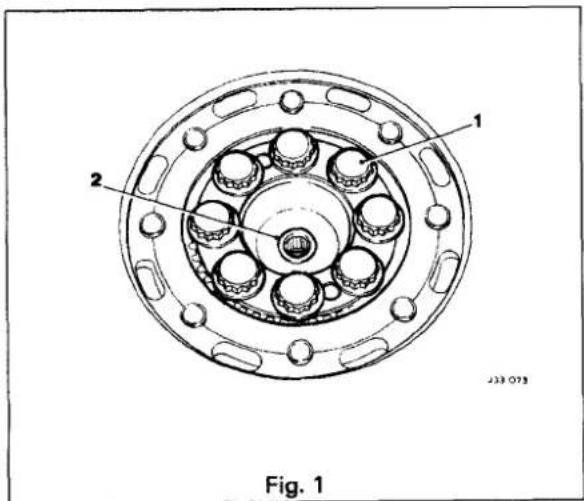


7.1.15 CLUTCH MASTER CYLINDER, RENEW
SRO 33.20.01
■ Remove the clutch master cylinder to clutch pedal clevis pin securing clip (1 Fig. 1), and remove the clevis pin (2 Fig. 1).
■ Removethe master cylinder securing nuts (3Fig. 1).
■ Disconnect the hydraulic pipe(4 Fig. 1) from the master cylinder, and fit blanking plugs to the pipe and master cylinder.
■ Remove the master cylinder assembly (5 Fig. 1) and the gasket (6 Fig. 1).
■ Fit the new master cylinder to the bench vice and fill the reservoir.
■ Refit the reservoir cap.
■ Remove the blanking plug from the master cylinder.
- Prime the master cylinder by 'working' the push rod until fluid appears at the hydraulic pipe outlet.
■ Remove the master cylinder from the vice.
■ Place a new gasket (6 Fig. 1) over the mounting studs.
■ Fit and align the master cylinder assembly to the studs, and secure with the nuts(3 Fig. 1).
■ Remove the blanking plug from the hydraulic pipe (4 Fig. 1).
■ Ensure that the union is clean and no foreign matter enters the system.

WARNING: USE ONLY CLEAN BRAKE FLUID OR DENA- TURED ALCOHOL (METHYLATEDSPIRITS)FOR CLEANING. ALL TRACES OF CLEANING FLUID MUST BE REMOVED BEFORE RE-ASSEMBLY. ALL COMPONENTS MUST BE LUBRICATED WITH CLEAN BRAKE FLUID AND ASSEMBLED USING THE FINGERS ONLY.
■ Reconnect the pipe(4 Fig. 1) to the master cylinder(5 Fig. 1), and tighten the union nut.
■ Align the push rod to the pedal.
■ Clean and grease the clevis pin (2 Fig. 1).
■ Align and fit the clevis pin to the pedal and push rod.
■ Fitthe securing clip (1 Fig. 1).
■ Bleed the clutch hydraulic system, see Sub-Section 7.1.18.

7.1.16 CLUTCH SLAVE CYLINDER, RENEW
SRO 33.35.01
■ Disconnect the pipe from the clutch slave cylinder, plug or tape the pipe to prevent the ingress of any dirt.
■ Remove the nuts (1 Fig. 1) and spring washers securing the slave cylinder to the transmission.
■ Remove the hose clip bracket (4 Fig. 1) complete with the hydraulic hose/ pipe(5 Fig. 1), and slide the slave cylinder (2 Fig. 1) off the mounting studs.
■ Slide the rubber boot along the push rod (3 Fig. 1) and withdraw the push rod from the cylinder.
■ To refit the new clutch slave cylinder, reverse the removal operations.
■ Bleed the clutch hydraulic system, see Sub-Section 7.1.18.
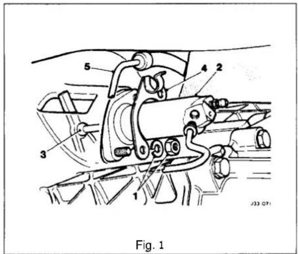

7.1.17 CLUTCH SLAVECYLINDER, OVERHAUL
SRO 33.35.07
■ Remove the clutch slave cylinder, see Sub-Section 7.1.16.
■ Dismantle the cylinder. The new parts in the kit will indicate which used parts should be discarded.
■ Clean the remaining parts and the cylinder thoroughly with unused brake fluid of the recommended type and place the cleaned parts on to a clean sheet of paper.
WARNING: USE ONLY CLEAN BRAKE FLUID OR DENATURED ALCOHOL (METHYLATED SPIRITS) FOR CLEANING. ALL TRACES OF CLEANING FLUID MUST BE REMOVED BEFORE RE-ASSEMBLY. ALL COMPONENTS MUST BE LUBRICATED WITH CLEAN BRAKE FLUID AND ASSEMBLED USING THE FINGERS ONLY.

- Examine the cylinder bore and the pistons for signs of corrosion, ridges or score marks. Provided the working surfaces are in perfect condition, new seals from the kit can be fitted, but if there is any doubt as to the condition of the parts then a new cylinder must be fitted.
■ Fitthe new seal(1 Fig. 2) to the piston(2 Fig. 2) with the flat back of the seal against the shoulder. - Lubricatethe seal and thecylinder bore with unused brake fluid of the recommended type and assemble thecylinder.
■ Before fitting the dust cover (3Fig.2), smear the sealing areas with rubber grease. - Squeeze the remainder of the grease from the sachet into the cover to help protect the internal parts.
■ Refit the clutch slave cylinder, see Sub-Section 33.15.01. - Bleed the clutch hydraulic system, see Sub-Section 7.1.18.

7.1


7.1.18 CLUTCHHYDRAULIC SYSTEM, BLEED
SRO 33.15.01
CAUTION: Only use minimumDOT 4 brake fluid in the hydraulic system.
■ Remove the reservoir filler cap, and top up to the correct level with hydraulic fluid.
■ Attach one end of a bleed tube (1 Fig. 1) to the slave cylinder bleed nipple (2 Fig. 1).
■ Partiallyfill a clean container (3 Fig. 1) with hydraulic fluid.
■ Immerse the other end of the bleed tube in the fluid.
■ Slacken the slave cylinder bleed nipple.
■ Pump the clutch pedal slowly up and down, pausing between each stroke.
■ Top up the reservoir with fresh hydraulic fluid after every three pedal strokes.
CAUTION: Do not use fluid bled from the system for top ping up purposes as this will contain air. If the fluid has been in use for some time it should be discarded. Fresh fluid bled from the system may be used after it has stood for a few hours allowing all the air bubbles to disperse.

- Pump the clutch pedal until the pedal becomes firm, tighten the bleed nipple.
■ Top up the reservoir, refit the filler cap.
■ Apply working pressure to the clutch pedalfor two to three minutes and examine the system for leaks.

SECTION CONTENTS
| Sub-Section Title | SRO | Page | |
| I to IV | Preliminary Pages | i | |
| 8.1.1 | General Description | 1 | |
| 8.1.2 | Transmission Fluid. Renew (3.2L and 4.0L) | 44.24.02 | 6 |
| 8.1.3 | Transmission Control Module. Renew (4.0L) | 44.15.32 | 7 |
| 8.1.4 | Transmission Rotary Switch. Adjust (4.0L) | 44.15.37 | 8 |
| 8.1.5 | Transmission Rotary Switch. Renew (4,0L) | 44.15.36 | 9 |
| 8.1.6 | Transmission Fluid Filter, Renew (3.2Land 4.0L) | 44.24.07 | 11 |
| 8.1.7 | Fluid Pan. Renew (4.0L) | 44.24.04 | 11 |
| 8.1.8 | Fluid Pan. Renew (3.2L) | 44.24.04 | 12 |
| 8.1.9 | Fluid Pan Gasket. Renew (3.2L) | 44.24.05 | 12 |
| 8.1.10 | Transmission Speed Sensor, Renew (4.0L) | 44.15.34 | 13 |
| 8.1.11 | Transmission Internal Harness Multi -pin Socket 'O' ring. Renew (4.0L) | 44.24.20 | 14 |
| 8.1.12 | Valve Body Assembly, Renew (4.0L) | 44.40.01 | 15 |
| 8.1.13 | Valve Body Assembly, Renew (3,2L) | 44.40.01 | 16 |
- SERVICE TOOLS & EQUIPMENT
| Illustration | Jaguar Number | Description Notes | ; | |
 | JD 103 | Throttle valve alignment tool | ||
| JD 161 | Rotary switch setting tool | |||
II. TORQUE TIGHTENING SPECIFICATIONS
| Fixing Tightening Torque | (Nm) |
| Dipstick tube union nut | 90 |
| Drain plug | 15 |
| Fluid filter screws | 8 |
| Fluid pan securing bolts | 8 |
| Rotary switch to mounting bracket nuts | 10- 12 |
| Switch guard to sump pan bolts | 15- 18 |
| Transmission oil cooler pipes | 20 |
- SERVICE MATERIALS
| Description | Uses | Notes |
| To be issued |
8.1
IV. SERVICE DATA
| Description | Data |
| To be issued |
8.1.1 GENERAL DESCRIPTION
This section provides information relating to the automatic transmissions fitted to the 32 liter engine (ZF 4 HP 22 transmission) and the 4,0 liter normally aspirated engine (ZF4 HP 24 E transmission). The general arrangement of the two units is shown in Fig. 1 and Fig. 2. The two automatic transmission units differ in the type of control unit employed: the purely hydraulic control used in the ZF 4 HP 22 unit shifts gears automatically at predetermined points, while the electronic-hydraulic control of the ZF 4 HP 24 E unit provides for optimized shift points and shift quality based on engine and transmission data received by the Transmission Control Module (TCM).

- Torque converter
2 Throttle cable - 4 -speed gear train
- Output flange
- Transmission control unit
- Oil outlet (drain plug)
-
Shift cable attachment
-
Shift lever positions:
'P' - Park
'R' - Reverse
'N' - Neutral
'D' -Drive - Fully automatic control
-
Dipstick/ oil filler tube
-
Oil cooler connection
Fig. 1 ZF 4 HP 22 Transmission

- Torque converter
- 4-speed gear train
- Output flange
- Transmission control unit
-
Oil outlet (drain plug)
-
Rotary switch positions:
'P' - Park
'R' - Reverse
'N' - Neutral
'D' -Drive (Fully automatic control) - Dipstick/ oil filler tube
- Oil cooler connection
Fig. 2 ZF 4 HP 24 E Transmission

Both types of automatic transmission comprise a hydrodynamic torque converter driving an epicyclic gear train which provides four forward ratios and reverse. Gearshift selection is made by a hydraulic (or electronic-hydraulic) transmission control unit. Six gearshift positions are provided:
Position 'P' (Park) – the driven wheels are mechanically locked at the transmission.
Position 'R' (Reverse)- reverse gear selected.
Position 'N' (Neutral) - engine disconnected from drive line and wheels.
Position 'D' (Drive) - all four speed ranges are selected automatically with lock-up available in top gear only.
Position '3' - automatic selection of the lowest three speed ranges only.
Position '2' automatic selection of the lowest two speed ranges only; the transmission is prevented from shifting up to the third and top speed ranges.
Immediate selection of a lower ratio is also available, within mapped limits, by 'kick-down' (pressing the accelerator pedal down beyond the normal full throttle position) for example when overtaking.
A brake pedal / gearshift interlock is incorporated in the shift lever mechanism. The shift lever may only be moved from the 'P' (Park) position if the ignition key switch is in position 'll', and the foot brake is applied. The ignition key cannot be removed from the ignition switch unless the shift lever is in the 'P' (Park) position. Once the ignition key has been removed, the shift lever is locked in the Park position. The gearshift interlock may be over-ridden manually in the event of an electrical failure or when it is required to move the vehicle manually for access, ie for removal of the propeller shaft.

8.1.1.1 Gear Selection (ZF4HP 22)
Gearshift selection causes the appropriate gear to be selected through a cable operated shift lever on the side of the transmission unit. When a gear is selected, the shift points are determined by accelerator pedal position through a throttle cable connection and by pressures equivalent to road speed derived from a centrifugal governor on the output shaft.
Gearshift speed and quality are controlled by the hydraulic control unit located in the lower part of the transmission housing. The control unit contains selector valve, control pistons and pressure valves.
The hydraulic control unit can be overridden by 'kickdown'. This is actuated by the final travel of the accelerator pedal and causes the next lower gear to be selected.
8.1.1.2 Gear Selection (ZF4HP 24E)
Gearshift selection causes the appropriate gear to be selected through a cable operated shift lever on the side of the transmission unit; the shift lever also operates a rotary switch attached to the side of the transmission unit. When a gear is selected, the rotary switch provides an output or combination of outputs to the TCM, which continuously monitors the gear selected in addition to output shaft speed and transmission oil temperature. Information from the Engine Control Module (ECM) representing engine speed, load and throttle position is also fed to the TCM to enable the most suitable gear to be selected.
Gear selection and gearshift speeds are controlled by the manually operated selector valve, a solenoid operated pressure regulator and three solenoid valves. On receipt of signals from the TCM, the three solenoid valves MV1, MV2 and MV3, in various combinations with the safety valve, determine the appropriate gear range. The TCM, on receipt of information of engine state and road speed, determines the shift speed.
The Performance Mode switch, located on the shift lever surround, provides two alternative shift speed patterns:
-
'Normal (Economy) Mode' - designed for everyday use.
-
'Sport Mode' - gear shift takes place at higher road speeds to enhance performance.
The 'kick-down' switch, located beneath the accelerator pedal, is actuated by the final travel of the pedal and signals to the TCM that the next lower gear is to be selected.

8.1.1.3 Shift Speeds
| 3,2 Liter | ||||
| Upshifts | ||||
| Light throttle | D1 - D2 | D2 - D3 | D3 - D4 | D4 - TCC on |
| mile / hkm / h | 10 - 1116 - 18 | 16 - 2326 - 37 | 24 - 2938 - 47 | 49 - 5379 - 85 |
| Up to 'kick-down point' | D1 - D2 | D2 - D3 | D3 - D4 | - |
| mile / hkm / h | 32 - 3851 - 61 | 58 - 6494 - 104 | 79 - 91127 - 147 | -- |
| Through 'kick-down point' | D1 - D2 | D2 - D3 | D3 - D4 | - |
| mile / hkm / h | 37 - 4360 - 69 | 65 - 71104 - 114 | 90 - 103145 - 166 | -- |
| Downshifts | ||||
| Zero throttle | TCC off in D4 | D4 - D3 | D3 - D2 | D2 - D1 |
| mile / hkm / h | 47 - 5176 - 82 | 16 - 2224 - 35 | 13 - 1422 - 23 | -- |
| Up to 'kick-down point' | D4 - D3 | D3 - D2 D2 | -D1 | - |
| mile / hkm / h | 64 - 71102 - 114 | 42 - 4867 - 78 36 | 22 - 31- 50 | -- |
| 'Kick-down' available | D4 - D3 D3 | -D2 D2 | -D1 | |
| mile / hkm / h | 86 - 99 61139 - 160 | -67 3098 - 108 48 | -37- 60 | -- |
| Manual inhibit (maximumavailable speed) | D4 - D3 D3 | -D2 | - | -- |
| mile / hkm / h | NOT INHIBITED 67 | -76108 - 123 | -- | -- |
TCC - Torque converter clutch
8.1


| 4,0 Liter | |||||
| Light throttle | D1 - D2 D2 | -D3 | D3 - D4 | D4 - TCC on | |
| Economy mile | /hkm/h | 10- 12 1416- 20 23 | - 21- 34 32 | 20 - 29- 47 | 45 - 5572 - 88 |
| sport mile | /hkm/h | 10 - 16 1616- 26 26 | - 24 25- 38 40 | - 33- 53 | 49 - 5979 - 95 |
| Economy mile | /hkm/h | 34- 38 5755- 61 | - 64 8891 - 103 | - 98141 - 157 | 88- 98141 - 157 |
| Sport | mile / hkm/h | 43 - 48 7369 - 77 | - 81117 - 130 | 110 - 119176 - 191 | 110 - 119176 - 191 |
| Through 'kick-down' point | |||||
| Economy / sport | mile / hkm/h | 43 - 4869 - 77 | 73 - 81117 - 130 | 110 - 119176 - 191 | 110 - 119176 - 191 |
| Zero throttle | D2 - D1 | D3 - D2 | D4 - D3 | D4 - TCC on | |
| Economy mile | /hkm/h | NOT AVAILABLE | 12 - 10 1520 - 16 | - 1324 - 21 | 49 - 3979 - 63 |
| sport mile | /hkm/h | 10 - 8 1216 - 13 20 | - 10 15- 16 | - 1324 - 21 | 52 - 3983 - 63 |
| Up to 'kick-down' point | |||||
| Economy mile | /hkm/h | 21 - 19 5234 - 31 | - 4783 - 75 | 86 - 77138 - 123 | 86 - 77138 - 123 |
| sport | mile / hkm/h | 30 - 2748 - 43 | 72 - 65115 - 104 | 109 - 99175 - 159 | 109 - 99176 - 159 |
| 'Kick-down' available | |||||
| Economy / sport | mile / hkm/h | 41 - 3566 - 56 | 73 - 64117 - 103 | 107 - 95171 - 152 | 107 - 95171 - 152 |
| Zero throttle | D2 - '1' | D3 - '2' | D4 - '3' | ||
| Economy mile | /hkm/h | 41 - 3566 - 56 | 73 - 64117 - 103 | 107 - 94171 - 152 | |
| sport mile | /hkm/h | 50 - 4480 - 71 | 85 - 75136 - 120 | 130 - 114208 - 182 | |
8.1


8.1.2 TRANSMISSION FLUID, RENEW
(3,2L AND 4,0L)
SRO 44.24.02
■ Raise the hood and fit a fender cover.
■ Raise the vehicle on a ramp.
■ Place a drain tin in position beneath the transmission drain plug.
- Release and remove the transmission drain plug; allow the fluid to drain.
■ Fit the drain plug with a new washer and torque tighten.
■ Reposition the drain tin beneath the dipstick tube union.
- Remove the screw securing the dipstick tube bracket.
■ Release the dipstick tube union nut and disconnect the tube from the fluid pan.
■ Drain the transmission fluid.
- Clean the tube unions, reconnect the dipstick tube to the fluid pan and torque tighten the union nut.
■ Lower the vehicle on the ramp.
■ Remove the transmission dipstick.
■ Renew the transmission fluid filter, see Sub-section 8.1.6.
- Fill the transmission with the correct fluid, see the ZF Automatic Transmissions Service Manual, General Data.
Note: It will not be possible to get all the initialfill quantity of fluid into the transmission.
■ Refit the dipstick.
■ Start the engine, apply all brakes and run the transmission through all gear positions and select 'Park'.
■ With the engine still running, remove the dipstick.
■ Clean the dipstick and refit.
■ Remove the dipstick and check the transmission fluid level.
■ Add fluid until the correct level is achieved.
■ Stop the engine and refit the dipstick.
■ Remove the fender cover and lower the hood.
- Check fluid level to the 'HOT' marks after a 20 mile road run to ensure accurate results.

8.1.3 TRANSMISSION CONTROL MODULE, RENEW (4,0L)
SRO 44.15.32
■ Raise the trunk lid and disconnect the battery.
■ Remove the passenger side dash liner for access.
- Displace and remove the air conditioning footwell outlet duct.
■ Release and remove the footwell carpet securing fastener: displace and reposition the carpet for access.
■ Release the Transmission Control Module (TCM) bracket to body bracket securing nut(1 Fig.1).
■ Displace the TCM mounting brackettang(2Fig. 1) from the body bracket and mounting stud.
- Reposition the TCM, release the TCM multi-pin plug lever lock and disconnect the multi-pin plug (3Fig. 1).
■ Release and remove the TCM mounting bracket securing bolts and remove the TCM.
- Fit and align the new TCM to the mounting bracket.
■ Fit and tighten the TCM securing bolts.
- Connect the TCM harness multi-pin plug and secure the multi-pin plug lever lock.
- Position the TCM to body mounting bracket, ensuring that the tang locates in the bracket slot and stud.
■ Fit and tighten the TCM securingnut.
■ Position the footwell carpet and fit the carpet fastener.
■ Fit and align the footwell outlet duct to air conditioning unit.
■ Position and fit the duct fastener to the blower motor slot.
■ Refit the dash liner.
■ Reconnect the battery.
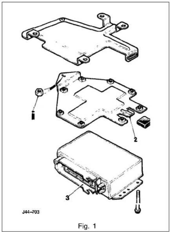
8.1.4 TRANSMISSIONROTARY SWITCH, ADJUST (4,0L)
SRO 44.15.37
■ Raise the vehicle on a ramp.
- Position the shift lever to 'N' ensuring that the stalk enters the gate 'N' notch centrally.
■ Release and remove the transmission unit rotary switch protection cover(1 Fig.1) to fluid pan bolts.
■ Remove the rotary switch protection cover from the fluid pan bosses.
■ Slacken the rotary switch to mounting bracket securing nuts.
- Displace the rubber blanking plug from the rotary switch center boss (2 Fig.1).
■ Fit Service Tool JD161 (Fig.2) to the rotary switch to align the switch rotor with the switch body.
CAUTION: Service Tool JD161 is a precision tool and should be treated as such.
■ Evenly torque tighten the rotary switch to mounting bracket securing nuts.
■ Disengage and remove Service Tool JD161 from the rotary switch.
■ Fully seat the rubber blanking plug into the rotary switch center boss.
■ Fit the rotary switch protection cover and align with the fluid pan bosses.
■ Fit and torque tighten the rotary switch protection cover to fluid pan securing bolts.
- Lower the vehicle on the ramp.
- Check for correct operation of start inhibit and gear selection.


8.1

8.1.5 TRANSMISSION ROTARY SWITCH, RENEW (4,0L)
SRO 44.15.36
■ Check the shift cable adjustment.
■ Switch the ignitionON, apply the footbrake and move the shift lever to 'N'.
- Switch the ignition OFF and disconnect the battery.
■ Open the armrest lid.
■ Release and remove the ashtray securing screws.
■ Displace the ashtray assembly for access.
■ Disconnect the cigar lighter / illumination harness conn ecbrs.
■ Place the ashtray assembly aside.
■ Displace and remove the console veneer panel rear finisher.
- Carefully displace the Performance Mode switch from the gear surround finisher.
- Disconnect the Performance Mode switch from the harness multi -pin plug.
- Displace and remove the Performance Mode switch surround finisher.
■ Displace and remove the shift lever surround finisher.
■ Release and remove the veneer panel wing nuts.
■ Displace and remove the console finisher veneer panel.
- Cut and remove the rotary switch harness securing straps.
- Disconnect the rotary switch harness multi-pin plugs.
■Reposition the tunnel carpet for access to the harness grommet.
- Displace and reposition the grommet down through the tunnel.
■ Feed the harness through the tunnel to the underside of the vehicle.
■ Raise the vehicle on a ramp.
■From beneath the vehicle, release and remove the rotary switch harness to transmission'P' clip securing nut; displace and reposition the 'P' clip from the stud.
■ Release and remove the rotary switch harness to transmission 'P' clip securing screw.
- Release and remove the rotary switch protection cover (1 Fig.1) securing bolts; displace and remove the switch cover.
- Disconnect the transmission multi-pin socket(2 Fig.1).
■ Reposition the harness clear of the transmission unit.
■ Release and remove the rotary switch securing nuts.
■ Displace and remove the switch assembly.
■ Displace and remove the 'P' clips from the harness.
■ Fit and align the 'P' clips to the new harness / switch assembly.
■ Displace the rubber sealing plug (3Fig.1) from the rotary switch.


■ Ensure the shift lever isin 'N'.
■ Fit and fully seat a new rotary switch to the transmission unit.
■ Fit but do not fully tighten the rotary switch securing nuts.
■ Fit and alignService Tool JD161 (Fig. 1) to the rotary switch to align the switch rotor to the switch body.
■ Finally torque tighten the rotary switch securing nuts.
- Displace and remove Service TooJD161.
■ Reposition and fit the rubber sealing plug to the switch.
■ Reconnect the transmission unit multi-pin plug.
- Reposition the harness and feed the multi-pin plugs and grommet through the tunnel aperture.
■ From below the vehicle, reposition the harness 'P' clip to its mounting stud.
■ Fit and tighten the 'P' clip securing nut.
- Align the harness'P' clip to transmission shift abutment bracket.
- Fit and tighten the 'P' clip securing screw.
■ Fit and align the rotary switch protection cover; fit and torque tighten the securing bolts.
■ From inside the vehicle, fit the grommet in the correct orientation and reposition the harness in the correct position.
■ Reconnect the rotary switch harness multi-pin plugs.
■ From below the vehicle, ensure that there is no excess slack in the switch harness that could foul the propshaft.
■ Lower the vehicle on the ramp.
■ Reposition and fit the tunnel carpet.
■ Usingsuitable tie straps, secure the harnessstothecomsole harness.
- Fit and fully seat the veneer panel to the console; fit and tighten the wing nuts.
Fit and fully seat the shift lever surround.
■ Connect the Performance Mode switch to the harness multi-pin plug and fully seat the switch.
■ Fit and align the console veneer panel rear finisher.
■ Placethe ashtray assembly in position.
■ Reconnect the cigar lighter / illumination harness connectors.
Reposition and fit the ashtray assembly; fit and tighten the securing screws.
■ Close the armrestlid.
■ Reconnect the battery.


8.1.6 TRANSMISSION FLUID FILTER, RENEW (3,2LAND 4,0L)
SRO 44.24.07
- Raise the hood and fit a fender cover.
■ Raise the vehicle on a ramp. - Drain the transmission lubrication system, see Sub-section 8.1.2.
■ Removethefluidpan, see Sub-section 8.1.7 (4,0L) or Sub-section 8.1.8 (3,2L).
■ Release and remove the fluid filter securing screws; displace and remove the fluid filter.
■ Remove and discard the filter 'O' ring.
■ Clean the new filter and mating faces.
■ Fit the 'O' ring to the new filtefit and seat the filter assembly to the valve body.
■ Fit and torque tighten the filter securing screws.
■ Refit the fluid pan, see Sub-section 8.1.7 (4,0L) or Sub-section 8.1.8 (3,2L).
■ Lower the vehicle on the ramp.
■ Refill the transmission unit with fluid, see Subsection 8.1.2.
■ Remove the fender cover and lower the hood.

8.1.7 FLUID PAN, RENEW (4,0L)
SRO 44.24.04
■ Raise the hood and fit a fender cover.
■ Raise the vehicle on a ramp.
- Drain the transmission lubrication system, see Sub–sec-tion 8.1.2.
■ Release and remove the rotary switch protection cover to fluid pan securing screws; remove the rotary switch protection cover.
- Release and remove the fluid pan securing bolts and clamps (1 Fig. 1). Displace and remove the fluid pan (2 Fig. 1).
- Drain the fluid pan. Remove and discard the fluid pan gasket if the gasket is damaged.
■ Removethe magnets from the fluid pan and place the fluid pan aside.
■ Clean the gasket faces and magnets.
■ Fit a serviceable gasket to the new fluid pan.
■ Fit the magnets in position in the fluid pan.
- Fit and align the fluid pan to the transmission unit; fit and torque tighten the fluid pan clamps and securing bolts.
■ Fit the rotary switch protection cover to the fluid pan bosses and fit and torque tighten the rotary switch protection cover securing bolts.
■ Lower the vehicle on the ramp.
■ Refill the transmission unit with fluid, see Subsection 8.1.2.
- Remove the fender cover and lower the hood.

8.1

8.1.8 FLUID PAN, RENEW (3,2L)
SRO 44.24.04
■ Raise the vehicle on a ramp.
- Drain the transmission lubrication system, see Sub–section 8.1.2.
■ Release and remove the fluid pan securing bolts and clamps (1 Fig. 1).
■ Displace and remove the fluid pan (2 Fig. 1).
- Drain the fluid pan. Remove and discard the fluid pan gasket if the gasket is damaged.
■ Remove the magnets from fluid pan and place the fluid pan aside.
■ Clean the gasket faces and magnets.
■ Fit a serviceable gasket to the new fluid pan.
■ Fit the magnets in position in the fluid pan.
- Fit and align thefluid pan to the transmission unit.
- Fit thefluid pan clamps; fit and torque tighten thefluid pan securing bolts.
■ Lower the vehicle on the ramp,
■ Raise the hood and fit a fender cover.
■ Refill the transmission unit with fluid, see Sub-section 8.1.2.
■ Remove the fender cover and lower the hood.

Fig. 1
■ Raise the hood and fit a fender cover.
■ Raise the vehicle on a ramp.
- Drain the transmission lubrication system, see Sub–section 8.1.2.
■ Release and remove the fluid pan securing bolts clamps (1 Fig. 1).
■ Displace and remove the fluid pan (2 Fig. 1).
■ Remove and discard the fluid pan gasket.
■ Removethe magnetsfrom the fluid pan and place the fluid pan aside.
■ Clean thfluid pan, gasket faces and the magnets.
■ Fit a ne fluid pan gasket.
■ Fit the magnets position in the fluid pan.
- Fit and align the fluid pan to the transmission unit, fit the fluid pan clamps, fit and torquetighten the fluid pan securing bolts.
■ Lower the vehicle on the ramp.
■ Refill the transmission unit with fluid, see Sub-section 8.1.2.
■ Remove the fender cover and lower the hood.

Fig. 1

8.1.10 TRANSMISSIONSPEED SENSOR, RENEW(4,0L)
SRO 44.15.34
- Raise the hood and fit a fender cover.
■ Raise the vehicle on a ramp. - Drain the transmission lubrication system, see Sub-section 8.1.2.
- Remove the fluid pan, see Sub-section 8.1.7.
■ Displace the transmission speed sensor harness from the valve body rear securing clip.
■ Release and remove the speed sensor and connector retaining clip from the valve body.
■ Displace the speed sensor and connector from the transmission main casing. - Disconnect and remove the speed sensor from the harness connector.
■ Clean the speed sensor, retaining clip and mating surface.
■ Connect the new speed sensor to the harness connector. - Fully seat the speed sensor into the transmission unit main casing.
■ Fit the speed sensor and connector retaining clip to the valve body, engaging the tangs onto the connector.
■ Fit and tighten the speed sensor and connector retaining clip securing screws.
■ Reposition and fully seat the speed sensor harness into the valve body rear; secure the clip.
■ Refit the fluid pan, see Sub-section 8.1.7.
■ Lower the vehicle on the ramp.
■ Refill the transmission unit with fluid, see Sub-section 8.1.2.
■ Remove the fender cover and lower the hood.

8.1


8.1.11 TRANSMISSION INTERNAL HARNESS MULTI-PIN SOCKET 'O'RING, RENEW (4,0L)
SRO 44.24.20
Raise the hood and it a fender cover.
■ Disconnect the battery.
■ Raise the vehicle on a ramp.
- Drain the transmission lubrication system, see Sub-section8.1.2.
■ Remove thefluid pan, see Sub-section 8.1.7.
■ Remove thefluid filter, see Sub-section 8.1.6.
■ Remove the transmission speed sensor, see Sub-section 8.1.10.
■ Disconnect the rotary switch harness multi-pin plug (1 Fig. 1) from the transmissionmulti-pin socket.
■ Release and remove the multi-pin socket to main transmission casing securingnut.
■ Release and remove the valve body assembly, ensuring that themulti-pinsocket is freed from the main case aperture.
- Remove the valve body harness multi-pin socket 'O' ring and discard.
■ Clean the valve body and mating faces.
■ Fit a new 'O' ring to themulti-pin socket
- Fit the valve body assembly to the transmission unit. During valve body fitment, engage the shift lever quadrant peg into the manual valve and seat the multi-pin socket through the main case orifice.
Note: The flat on the side of the multi-pin socket should be located on the vertical (left-hand) side of the case.
■ Fit but do not tighten the valve body assembly securing screws.
■ Gently push the valve body assembly forward to assume this position during the final tightening operation.
- Carry out final tightening of the valve body assembly to main casing securing screws.
Fit and tighten the harness multi-pinsocket to main casing securing nut.
- Connect the rotary switch harness multi-pin plug to the transmission multi-pin socket.
■ Refit the speed sensor, see Sub-section 8.1.10.
■ Renew the fluid filter, see Sub-section 8.1.6.
■ Refit thleuid pan, see Sub-section 8.1.7.
■ Lower the vehicle on the ramp.
■ Reconnect the battery.
■ Refill the transmission unit with fluid, see Sub-section 8.1.2.
■ Remove the fender cover and lower the hood.
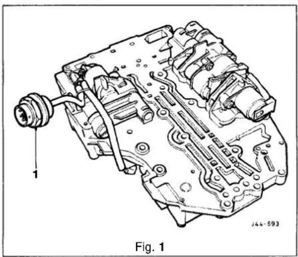

8.1.12 VALVE BODY ASSEMBLY, RENEW(4,0L)
SRO 44.40.01
■ Raise the hood and fit a fender cover.
■ Disconnect the battery.
■ Raise the vehicle on a ramp.
- Drain the transmission lubrication system, see Sub-section 8.1.2.
■ Remove the fluid pan, see Subsection 8.1.7.
■ Remove the fluid filter, see Sub-section 8.1.6.
■ Remove the transmission speed sensor, see Subsection 8.1.10.
■ Disconnect the rotary switch harness multi-pin plug from the transmission multi-pin socket.
■ Release and remove the multi-pin socket to main transmission casing securing nut.
- Release and remove the valve body assembly to main casing securing screws.
- Displace and remove the valve body assembly, ensuring that the multi-pin socket is freed from the main case aperture.
- Remove the valve body harness multi-pin socket 'O' ring and discard.
■ Clean the valve body and main case mating faces. Check for any signs of damage.
■ Fit a new 'O' ring to the multi-pin socket.
■Fit the valve body assembly to the transmission unit. During valve body fitment, engage the shift lever quadrant peg into the manual valve and seat the multi-pin socket through the main case orifice.
Note: The flat on the side of the multi-pin socket should be located on the vertical (left-hand) side of the case.
■Fit but do not tighten the valve body assembly securing screws.
- Gently push the valve body assembly forward to assume this position during the final tightening operation.
- Carry out final tightening of the valve body assembly to main casing securing screws.
- Fit and tighten the harness multi – pin socket to main casing securing nut.
■ Connect the rotary switch harness multi -pin plug to the transmission multi -pin socket.
■ Refit the speed sensor, see Subsection 8.1.10.
■ Renew the fluid filter, see Subsection 8.1.6.
■ Refit the fluid pan, see Sub-section 8.1.7.
■ Lower the vehicle on the ramp.
■ Reconnect the battery.
■Refill the transmission unit with fluid, see Sub-section 8.1.2.
■ Remove the fender cover and lower the hood.


8.1
8.1.13 VALVE BODY ASSEMBLY, RENEW (3,2L)
SRO 44.40.01
■ Raise the hood and it a fender cover.
- Disconnect the battery.
■ Raise the vehicle on a ramp.
- Drain the transmission lubrication system, see Su -section 8.1.2.
■ Remove the fluid pan, see Sub-section 8.1.8.
■ Remove the fluid filter, see Subsection 8.1.6.
■ Release and remove the valve body securing screws (1 Fig. 1).
- Displace and remove the valve body assembly.
■ Clean the valve body and mating faces.
- Fit the new valve body to the transmission unit, locating the throttle valve behind the throttle valve cam and engage the selector.
■ Fit but do not tighten the valve body securing screws.
■ Fit and engage Service Tool JD 103 between the valve body and the throttle valve pin.
- Align the valve body assembly.
■ Fully tighten the valve body securing screws.
■ Remove Service Tool JD 103.
- Fit a new fluid filter, see Sub-section 8.1.6.
■ Refit the fluid pan, see Subsection 8.1.8.
■ Lower the vehicle on the ramp.
■ Refill the transmission unit with fluid, see Subsection 8.1.2.
■ Remove the fender cover and lower the hood.

SECTION CONTENTS
| Sub-Section Title | SRO | Page | |
| I to IV | Preliminary Pages | i | |
| 8.2.1 | General Description | 1 | |
| 8.2.2 | Transmission internal Harness. Renew (4. OL SC and 6. OL) | 44.15.35 | 5 |
| 8.2.3 | Pressure Switch Manifold. Renew (4. OL SC and 6. OL) | 44.15.39 | 6 |
| 8.2.4 | Input Speed Sensor, Renew (4. OL SC) | 44.15.40 | 7 |
| 8.2.5 | Output Speed Sensor, Renew (4. OL SC) | 44.15.41 | 7 |
| 8.2.6 | input Speed Sensor, Renew (6. OL) | 44.15.40 | 8 |
| 8.2.7 | Output Speed Sensor, Renew (6. OL) | 44.15.41 | 9 |
| 8.2.8 | Temperature Sensor, Renew (4. OL SC and 6. OL) | 10 | |
| 8.2.9 | Variable Force Motor, Renew (4. OL SC and 6. OL) | 44.15.43 | 70 |
| 8.2.10 | Pulse Width Modulator (TCC Solenoid). Renew (4. OL SC and 6. OL) | 44.15.44 | 11 |
| 8.2.11 | 'A' Shift Solenoid. Renew (4. OL SC and 6. OL) | 44.15.45 | 12 |
| 8.2.12 | 'B' Shift Solenoid. Renew (4. OL SC and 6. OL) | 44.15.46 | 13 |
| 8.2.13 | Lubrication System. Drain and Refill (4. OL SC and 6. OL) | 44.24.02 | 14 |
| 8.2.14 | Fluid Pan. Renew (4. OL SC) | 44.24.04 | 15 |
| 8.2.15 | Fluid Pan. Renew (6. OL) | 44.24.04 | 16 |
| 8.2.16 | Fluid Pan Gasket. Renew (4. OL SC) | 44.24.05 | 17 |
| 8.2.17 | Fluid Pan Gasket. Renew (6. OL) | 44.24.05 | 18 |
| 8.2.18 | Fluid Filter, Renew (4. OL SC and 6. OL) | 44.24.07 | 19 |
| 8.2.19 | Transmission Internal Harness Multi -pin Socket 'O' Ring. Renew (4. OL SC and 6. OL) | 44.24.20 | 20 |
| 8.2.20 | Internal Lubrication Pipe. Renew (4. OL SC and 6. OL) | 44.24.21 | 21 |
| 8.2.21 | internal Dipstick Stop. Renew (4. OL SC and 6. OL) | 44.24.22 | 22 |
| 8.2.22 | Manual Detent Spring. Renew (4. OL SC and 6. OL) | 44.26.10 | 23 |
8.2
1. SERVICE TOOLS & EQUIPMENT
No Jaguar service tools are required for the operations covered by this Sub-section.
| Fixing | lightening Torque (Nm) |
| Drain plugto fluid pan | 34 |
| Fluid panto case | 24 |
| Pressure control solenoid bracketto valve body | 8 |
| Solenoid to valve body | 8 |
| Speed sensor and bracket assembly to case | 11 |
| Valve body to case / lubrication pipe | 11 |
| Valve body to case/ PSM | 11 |
| Description | Uses | Notes |
| Tivoli Kay Adhesives No. 5696 sealant | Exhaust system joints |
| Description | Data |
| To be issued |
8.2
8.2.1 GENERAL DESCRIPTION
This section provides information relating to the Powertrain4L80-E transmissions fitted to the 4,0 liter supercharged engine (4,0L SC) and to the 6,0 liter engine (6,0L).
The Powertrain4L80-E is a four-speed, high torque capacity, electronically controlled automatic transmission, which comprises a torque converter with lock-up direct drive clutch and three planetary gear sets. Five multiple diskclutches, one intermediate sprag clutch assembly, two roller clutch assemblies and two band assemblies provide the drive elements necessary for correct sequential gear engagement and operation.
The torque converter containing a pump, a turbine (rotor), a stator assembly, and a clutch pressured disksplined to the turbine, acts as a fluid coupling for smooth torque transmission from the engine. The converter also supplies additional torque multiplication when necessary, and the torque converter clutch (TCC) pressuredisk provides a mechanical direct drive or 'lock-up' above a certain speed in top gear for greater fuel economy.
Gearshift operations are controlled from the Transmission Control Module (TCM), which governs the electronically controlled valve body situated within the transmission.
Three planetary gear sets provide reverse and the four forward ratios, the changing of which is fully automatic in relation to load, vehicle speed and throttle opening. The Transmission Control Module receives and integrates various vehicle sensor input signals, and transmits operating signals to the solenoids located in the control valve assembly. These solenoids govern the transmission operating pressures, up-shift and down-shift gear selection patterns and also the torque converter clutch operation by pulse width modulated control.
8.2.1.1 Gear Ranges
Selectable gear positions are: P - Park, R - Reverse, N - Neutral, D - Drive, 3, 2.
P - Park position of the shift lever provides mechanical locking of the output shaft of the transmission, and as such, must only be engaged when the vehicle is stationary. In addition, and for extra safety, the handbrake should also be applied. It is necessary to have the ignition ON and the footbrake applied to move the shift lever from the Park position. For ignition key removal the shift lever must be in the Park position. The engine can be started in the Park position.
R - Reverse enables the vehicle to be operated in a rearwards direction. The engine cannot be started in the Reverse position.
N- Neutral position enables the engine to be started and operated without driving the vehicle. It also allows the vehicle to be moved manually for access, ie for removal of the propeller shaft.
D - Drive position allows the automatic selection of all four forward gear ratios during normal driving conditions for maximum efficiency and fuel economy. On acceleration, down-shifts are obtained by depressing the accelerator pedal or by manual selection. The engine cannot be started in this position.
3 - Manual third position allows automatic operation of the three lower gear ratios but inhibits selection of the fourth ratio. This position is used for towing a trailer or negotiating hilly terrain when greater engine braking control is required. The engine cannot be started in this position.
2 - Manual second position allows automatic operation of the two lower gear ratios but inhibits selection of the third and fourth ratios. This position is used for heavy traffic congestion or negotiating hilly terrain when even greater engine braking control is required than is provided by manual third. This ratio may be selected at any vehicle speed - even if the transmission is in third or fourth ratio, the transmission will immediately down - shift to second gear provided the vehicle speed is below 137km / h (85 mile/ h). The engine cannot be started in this position.

8.2


- Torque converter
- Turbine shaft
- Pressure disk
- Converter turbine
- Converter stator
- Variable force motor solenoid
- Fluid pan
- Filter
- Interior detent lever
- Manual shaft
- Control valve
- Front band
-
Parking lock actuator
-
Rear band
- Sun gear shaft
- Sun gear
- Parking lock pawl
- Transmission case
- Output shaft
- Rear extension housing
- Rear internal gear
- Output planetary carrier assembly
- Reaction planetary carrier assembly
- 'LO' roller clutch
-
Main shaft
-
Intermediate clutch
- Intermediate sprag clutch
- Direct clutch
- Forward clutch
- Overdrive planetary carrier assembly
- Overdrive roller clutch
- Overrun clutch
- Fourth clutch
- Pump assembly
- Converter pump
- Stator roller clutch
- Output speed sensor
Fig.1 Powertrain 4L80–E automatic transmission
8.2.1.2 Shift Speeds
| 4,0 Liter Supercharged | |||||
| Light throttle | D1 - D2 D2 | - D3 D3 | - D4 | D4 - TCC on | |
| Normal mile | /hkm/h | 8 - 10 1813 - 15 28 | - 20 25- 33 40 | - 39- 46 | 45 - 5172 - 83 |
| sport mile | /hkm/h | 10 - 12 2016 - 19 32 | - 23 30- 37 48 | - 34- 55 | 47 - 5576 - 88 |
| Up to Detent | D1 - D2 D2 | - D3 | D3 - D4 | ||
| Normal mile | /mile/hkm/h | 34 - 37 6054 - 59 97 | - 66- 107 | 86 - 94138 - 151 | |
| sport | 43 - 4769 - 76 | 74 - 81118 - 130 166 | 103 - 113- 182 | ||
| Maximum shift speeds (through detent) | D1 - D2 | D2 - D3 | D3 - TCC on | ||
| Normal / Sport | mile/hkm/h | 47 - 5075 - 80 | 81 - 84130 - 134 187 | 116 - 128- 205 | |
| Zero throttle | TCC off in D4 | D4 - D3 D3 | - D2 | D2 - D1 | |
| Normal mile | /hkm/h | 36 - 4058 - 64 | 15 - 1724 - 27 | 10 - 1216 - 19 | -- |
| sport | mile/hkm/h | 36 - 4058 - 64 | 18 - 2029 - 32 | 12 - 1420 - 22 | 9 - 914 - 15 |
| Up to detent | D4 - D3 | D3 - D2 | D2 - D1 | ||
| Normal mile | /mile/hkm/h | 67 - 74107 - 118 | 39 - 4463 - 70 | 9 - 914 - 15 | |
| sport | 81 - 89130 - 144 92 | 57 - 63- 101 | 27 - 2943 - 47 | ||
| Kick-down available (throughdetent) | TCC4 - D3 | D3 - D2 | D2 - D1 | ||
| Normal / Sport | mile/hkm/h | 103 - 113165 - 183 | 67 - 74107 - 118 | 36 - 4058 - 64 | |
TCC - Torque converter clutch
Note: Road speeds shown above are for a vehicle with an axle ratio of 3,58:1, and standard tyres (225/65ZR15). For a vehicle with optional sports tyres (225/55ZR16) (lattice wheels), these speeds must be reduced by 2,4%.
8.2
| 6,0 Liier | |||||
| Light throttle | D1 - D2 | D2 - D3 | D3 - D4 D4 | - TCC on | |
| Normal mile | /hkm / h | -- | 20 - 2332 - 37 | 29 - 33 4846 - 52 77 | - 55- 88 |
| sport mile | /hkm l h | 10- 1216- 18 | 23 - 26 3236 - 41 | - 3751 - 59 | 51 - 5982 - 94 |
| Up to detent | D1 - D2 D2 | - D3 | D3 - D4 | ||
| Normal mile | /hkm l h | 35 - 40 6156 - 64 98 | - 70- 112 133 | 83 - 91- 164 | |
| sport mile | /hkm / h | 43 - 49 7368 - 78 | - 79117- 127 | 99 -107158 - 172 | |
| Maximum shift speeds (through detent) | D1 - D2 | D2 - D3 | D3 - TCC on | ||
| Normal / Sport | mile / hk ml h | 48 - 5377 - 85 | 81 - 89130- 149 | 116- 124186 - 198 | |
| Zero throttle | TCC off in D4 | D4 - D3 | D3 - D2 | D2 - D1 | |
| Normal mile | /hkm l h | 36- 4058 - 64 | 15 - 1724 - 27 | 10 - 1216 - 19 | -- |
| sport | mile / hkm / h | 36- 4058 - 64 29 | 18 - 20 12- 32 19 | - 14- 22 | 6 - 710 - 12 |
| Up to detent | D4 - D3 | D3 - D2 | D2 - D1 | ||
| Normal mile | /hkm l h | 67 - 75108 - 119 | 37 - 4159 - 66 | 7 - 911 - 14 | |
| sport mile | /hkm / h | 84 - 92134 - 148 | 60 - 66 2796 - 106 | - 2943 - 47 | |
| 'Kick-down' available (through detent) | TCC4 - D3 | D3 - D2 | D2 - D1 | ||
| Normal / Sport | mile / hkm / h | 103 - 113164 - 181 | 67 - 75108 - 119 | 36 - 4058 - 64 | |
TCC - Torque converter clutch
Note: Roadspeeds shown above are for a vehicle with an axle ratio of 3,58:1, and standard tyres(225/65ZR15). For a vehicle with optional sports tyres (225/55ZR16) (lattice wheels), these speeds must be reduced by 2,4%.
8.2

8.2.2 TRANSMISSION INTERNAL HARNESS, RENEW (4,0L SC AND 6,0L)
SRO 44.15.35
■Open the hood and fit a suitable fender cover.
■ Raise the vehicle on a ramp,
- Drain the transmission lubrication system, see Sub–sec-tion 8.2.13.
■ Remove the fluid pan, see Sub-section 8.2.14 (4,0L SC) or Sub-section 8.2.15 (6,0L).
Note: Note the internal harness cable runs for assembly purposes and remove the transmission internal harness multi-pin socket (1 Fig. 1), discarding the 'O' ring seal (2 Fig. 1); see Sub-section 8.2.19.
■ Disconnect the internal harness plug from the 'A' Shift solenoid.
■ Disconnect the internal harness plug from the 'B' Shift solenoid.
■ Disconnect the internal harness plug from the pressure switch manifold.
■ Disconnect the internal harness plug from the pulse width modulator (TCC solenoid).
■ Disconnect the internal harness plug from the variable force motor.
■ Displace the internal harness from the retaining clips.
■ Remove the internal harness from the transmission unit.
■ Place the harness aside.
■ Clean all relevant parts.
■ Fit the new internal harness to the transmission unit.
■ Secure the internal harness to its retaining clips.
■ Connect the internal harness plug to the variable force motor.
■ Connect the internal harness plug to the pulse width modulator.
■ Connect the internal harness plug to the pressure switch manifold.
■Connectthe internal harness plugto the 'B' Shift solenoid.
■Connect the internal harness plug to the 'A' Shift solenoid.
- Fit a new internal harness multi-pin socket 'O ring, refit the multi-pin socket to the main case and connect the external harness, see Subsection 8.2.19.
■ Refit the fluid pan, see Subsection 8.2.14 (4,0L SC) or Sub-section 8.2.15 (6,0L).
■ Lower the vehicle on the ramp.
■ Refill the transmission unit with fluid, see Subsection 8.2.13.
■ Remove the fender cover and close the hood.
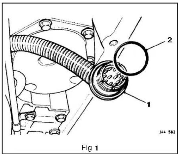


8.2
8.2.3 PRESSURE SWITCH MANIFOLD, RENEW (4,0L SC AND 6,0L)
SRO 44.15.39
■ Open the hood and fit suitable fender cover.
■ Raise the vehicle ona ramp.
■ Drainthe transmission lubrication system, see Subsection 8.2.13.
■ Remove the fluid pan, see Sub-section 8.2.14 (4,0L SC) or Sub-section 8.2.15 (6,0L).
■ Remove the fluid filter, see Sub-section 8.2.18.
- Disconnect the internal harness plug from the pressure switch manifold.
■ Release and remove the pressureswitch manifold to valve body securing bolts.
■ Remove the manifold from the valve body.
■ Retrieve the manifold to valve body 'O' ring seals (Fig.1) and discard.
- Clean the valve body manifold seating area.
■ Fit new 'O' ring seal to the grooves in a new pressure switch manifold.
• Fit the manifold to the valve body.
■ Fit and tighten the manifold to valve body securing bolts.
- Connect the internal harness plug to the pressure switch manifold.
■ Refit the fluid filter, see Sub-section 8.2.18.
- Refit the fluid pan, see Sub-section 8.2.14 (4,0L SC) or Sub-section 8.2.15 (6,0L).
■ Lower the vehicle on the ramp.
■ Refill the transmission unit with fluid, see Sub-section 8.2.13.
■ Remove the fender cover and close the hood.


8.2.4 INPUT SPEED SENSOR, RENEW (4,0L SC)
SRO 44.15.40
■ Raise the vehicle on a ramp.
■ Reposition the edge of the transmission tunnel sound insulation foam for access.
■ Disconnect the harnessplug from the input speed sensor.
■ Release and remove the speed sensor securing bolt.
■ Reposition the speed sensor protection cover for access; the cover remains captive on the harness.
■ Remove the speed sensor from the transmission unit and place aside.
■ Clean the main case speed sensor area.
■ Fit a new 'O' ring seal to a new input speed sensor.
■ Lubricate the 'O' ring seal.
■ Fit and seat the speed sensor to the main case.
■ Reposition and align the speed sensor protection cover.
■ Fit and tighten the speed sensor securing bolt.
■ Connect the harness plug to the speed sensor.
- Reposition the edge of the transmission tunnel sound insulation foam to the original position.
■ Lower the vehicle on the ramp.

8.2.5 OUTPUT SPEED SENSOR, RENEW (4,0L SC)
SRO 44.15.41
■ Raise the vehicle on a ramp.
■ Reposition the edge of the transmission tunnel sound insulation foam for access.
■ Disconnect the harness plug from the output speed sensor.
■ Release and remove the speed sensor securing bolt.
■ Reposition the speed sensor protection cover for access, noting that the cover remains captive on the harness.
■ Remove the speed sensor from the transmission unit and place aside.
■ Clean the main case speed sensor area.
■ Fit a new 'O ring seal toa new output speed sensor.
■ Lubricate the 'O ring seal.
■ Fit and seat the speed sensor to the main case.
■ Reposition and align the speed sensor protection cover.
■ Fit and tighten the speed sensor securing bolt.
■ Connect the harness plug to the speed sensor.
- Reposition the edge of the transmission tunnel sound insulation foam to the original position.
■ Lower the vehicle on the ramp.

8.2

8.2.6 INPUT SPEED SENSOR, RENEW(6,0L)
SRO 44.15.40
■ Open the hood and fit a suitable fender cover.
■ Raise the vehicle on a ramp.
■ Slacken the underfloor catalyst to downpipe clamps securing bolts.
■ Displace and reposition the olive clamps on the pipes.
Slacken the underfloor catalyst to intermediate silencer clamps securing bolts.
- Displace the underfloor catalyst assembly rearwards to disconnect from the downpipes.
- Displace and remove the olives from the downpipes.
■ Using a wire brush, clean the olives and downpipe joints.
■ Place a suitable piece of wood between the underfloor catalyst and the body for access.
■ Reposition the edge of the transmission tunnel insulation foam for access.
■ Release and remove the input speed sensor securing bolt.
■ Reposition the speed sensor protection cover for access, noting that the cover remains captive on the harness. Disconnect the speed sensor harness multi-pin plug.
- Displace and remove the speed sensor from the transmission case.
- Clean the transmission case area.
■ Fit a new 'O' ring seal to a new input speed sensor.
■ Lubricate the 'O ring seal.
■ Fit and fully seat the speed sensor to the transmission case.
■ Reconnect the harness multi-pin plug.
■ Reposition and align the protection cover.
■ Fit and tighten the speed sensor securing bolt.
- Reposition the insulation foam to its original position.
- Remove the block of wood from between the underfloor catalyst and the floor.
■ Apply sealant to the downpipe joints and olives. See Service Materials in the preliminary pages, this Section.
- Fit and seat the olives to the downpipes.
Reconnect the underfloor catalyst to the downpipes.
- Reposition the olive clamps.
- Tighten the underfloor catalyst to downpipe clamps securing bolts.
- Align the intermediate silencers to the underfloor catalyst assembly.
■ Tighten the clamp securing bolts.
■ Lower the vehicle on the ramp.
■ Remove the fender cover and close the hood.

8.2.7 OUTPUT SPEEDSENSOR, RENEW (6,0L)
SRO 44.15.41
■ Open the hood and fit a suitable fender cover.
■ Raise the vehicle on a ramp.
■ Slacken the underfloor catalyst to downpipe clamps securing bolts.
- Displace and reposition the olive clamps on the pipes. - Slacken the underfloor catalyst to intermediate silencer cl amps securing bolts.
■ Displace the underfloor catalyst assembly rearwards to disconnect from the downpipes.
■ Displace and remove the olives from the downpipes.
■ Using a wire brush, clean the olives and downpipe joints.
- Place a suitable piece of wood between the underfloor catalyst and the body for access.
■ Reposition the edge of the transmission tunnel insulation foam for access.
■ Release and remove the output speed sensor securing bolt.
■ Reposition the speed sensor protection cover for access, noting that the cover remains captive on the harness.
■ Disconnect the speed sensor harness multi-pin plug.
■ Displace and remove the speed sensor from the transmission case.
■ Clean the transmission case sensor area.
■ Fit a new 'O' ring seal to a new output speed sensor.
■ Lubricate the 'O' ring seal.
- Fit and fully seat the speed sensor to the transmission case.
■Reconnect the harnessmulti-pin plug.
- Reposition and align the protection cover.
■ Fit and tighten the speed sensor securing bolt.
■ Reposition the insulation foam to its original position.
■ Remove the block of wood from between the underfloor catalyst and the floor.
■ Apply sealant to the downpipe joints and olives. See Service Materials in the preliminary pages, this Section.
■ Fit and seat the olives to the downpipes.
■ Reconnect the underfloor catalyst to the downpipes.
■ Reposition the olive clamps.
■ Tighten the underfloor catalyst to downpipe clamps securing bolts.
- Align the intermediate silencers to the underfloor catalyst assembly.
■Tighten the clamp securing bolts.
■ Lower the vehicle on the ramp.
■ Remove the fender cover and close the hood.


8.2
8.2.8 TEMPERATURE SENSOR, RENEW (4,0L SC AND 6,0L)
The temperature sensor forms part of the internal wiring harness. Should the sensor require replacement, a new wiring harness must be fitted. See Subsection 8.2.2.
8.2.9 VARIABLE FORCE MOTOR, RENEW (4,0L SC AND 6,0L)
SRO 44.15.43
■ Open the hood and fit a suitable fender cover.
■ Raise the vehicle on a ramp.
- Drain the transmission lubrication system, see Sub–sec-tion 8.2.13.
- Remove the fluid pan, see Subsection 8.2.14(4,0L SC) or Sub-section 8.2.15(6,0L).
- Remove the fluid filter, see Subsection 8.2.18.
- Disconnect the internal harness plug from the variable force motor.
- Release and remove the motor retaining clamp to valve body securing screw (1Fig.1).
■ Remove the retaining clamp (2 Fig.1) and remove the motor (3Fig.1) from the valve body and place aside.
• Fit a new variable force motor to the valve body.
CAUTION: Do not adjust the motor screw and ensure that the motor filter is not damaged.
■ Align the motor.
■ Fit the motor to the valve body retaining clamp.
■ Fit and tighten the motor retaining clamp securing screw.
■ Connect the internal harnessplugto the motor.
■ Refit the fluid filter, see Sub-section 8.2.18.
■ Refit the fluid pan, see Subsection 8.2.14 (4,0L SC) or Sub-section 8.2.15 (6,0L).
■ Lower the vehicle on the ramp.
■ Refill the transmission unit with fluid, see Subsection 8.2.13.
- Remove the fender cover and close the hood.


8.2.10 PULSE WIDTH MODULATOR (TCC SOLENOID), RENEW (4,0L SC AND 6,0L)
SRO 44.15.44
■ Open the hood and fit a suitable fender cover.
■ Raise the vehicle on a ramp.
- Drain the transmission lubrication system, see Sub-section 8.2.13.
■ Remove thefluid pan, see Subsection 8.2.14 (4,0L SC) or Subsection 8.2.15 (6,0L).
■ Remove the fluid filter, see Subsection 8.2.18.
- Disconnect the internal harness plug from the pulse width modulator.
■ Remove the modulator to valve body retaining clip.
- Displace and remove the modulator from the valve body, noting the orientation.
■ Remove and discard theO' ring seals from the modulator.
- Place the modulator aside.
- Fit new 'O' ring seals to a new pulse width modulator.
■ Lubricate the 'O' ring seals.
■ Fit and seat the modulator, in the correct orientation, to the valve body using a twisting motion.
■ Fit the pulse width modulator to valve body retaining clip.
■ Connect the internal harness plug to the modulator.
■ Refit the fluid filter, see Subsection 8.2.18.
■ Refit the fluid pan, see Subsection 8.2.14 (4,0L SC) or Sub-section 8.2.15 (6,0L).
■ Lower the vehicle on the ramp.
■ Refill the transmission unit with fluid, see Subsection 8.2.13.
■ Remove the fender cover and close the hood.

8.2


8.2.11 'A' SHIFT SOLENOID, RENEW
(4,0L SC AND 6,0L)
SRO 44.15.45
- Open the hood and fit suitable fender cover.
■ Raise the vehicle on a ramp. - Drain the transmission lubrication system, see Sub–sec-tion 8.2.13.
■ Remove thefluid pan, see Sub-section 8.2.14(4,0L SC) or Sub-section 8.2.15(6,0L). - Disconnect the internal harness plug from the 'A' Shift solenoid.
■ Release and remove the 'A' Shift solenoid to valve body securing screw.
■ Remove the solenoid from the valve body (Fig. 1). - Remove and discard the 'O' ring sealfrom the valve body.
■ Place the solenoid aside.
■ Fit a new 'O ring seal to a newA' Shift solenoid.
■ Lubricate the 'O' ring seal.
• Fit the solenoid to the valve body using a twisting motion.
■ Fit and tighten the solenoid to the valve body using a new securing screw.
■ Connect the internal harness plug to the solenoid.
■ Refit the fluid pan, see Sub-section 8.2.14 (4,0L SC) or Sub-section 8.2.15 (6,0L).
■ Lower the vehicle on the ramp.
■ Refill the transmission unit with fluid, see Sub-section 8.2.13. - Remove the fender cover and close the hood.
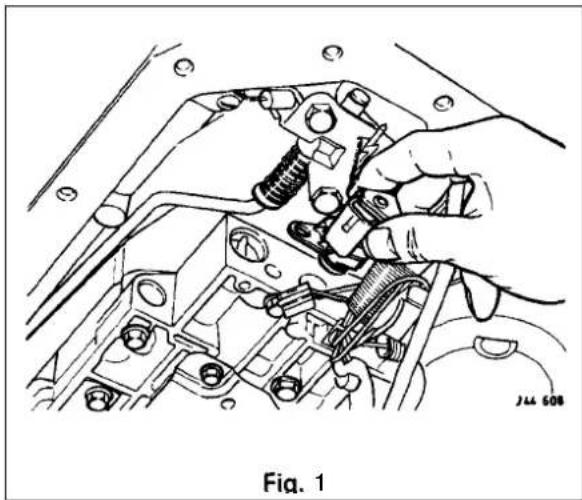
8.2

8.2.12 'B' SHIFT SOLENOID, RENEW (4,0L SCAND 6,0L)
SRO 44.15.46
- Open the hood and fit a suitable fender cover.
■ Raise the vehicle on a ramp.
- Drain the transmission lubrication system, see Sub–sec-tion 8.2.13.
■ Removethe fluid pan, see Subsection 8.2.14 (4,0L SC) or Subsection 8.2.15 (6,0L).
■ Disconnect the internal harness plug from the 'B' Shift solenoid.
■ Release and remove the 'B' Shift solenoid to valve body securing screw.
- Remove the solenoid from the valve body (Fig. 1). - Remove and discard the 'O' ring seal from the solenoid.
■ Place the solenoid aside.
■ Fit a new 'O' ring seal to a new 'B' Shift solenoid.
■ Lubricate the 'O' ring seal.
■ Fit the solenoid to the valve body using atwisting motion.
■ Fit and tighten the solenoid to the valve body using a new securing screw.
■ Connect the internal harness plug to the solenoid.
■ Refit the fluid pan, see Subsection 8.2.14 (4,0L SC) or Sub-section 8.2.15(6,0L).
- Lower the vehicle on the ramp.
- Refill the transmission unit with fluid, see Subsection 8.2.13.
■ Remove the fender cover and close the hood.


8.2


8.2.13 LUBRICATION SYSTEM, DRAIN AND REFILL (4,0L SC AND 6,0L)
SRO 44.24.02
■ Raise the vehicle on a ramp.
■ Position a drain tin below the transmission unit.
■ Release and remove the fluid pan drain plug.
■ Allow the fluid to drain.
- Clean the drain plug, including the magnet and the fluid pan drain plug face.
■ Fit and tighten the fluid pan drain plug.
■ Remove the drain tin from below the transmission unit.
■ Lower the vehicle on the ramp.
Open the hood and fit a suitable fender cover.
Remove and wipe the dipstick.
■ Fit a funnel to the dipstick tube.
■ Initially fill the transmission with 4,5 liters of fluid.
■ Remove the funnel.
■ Open the front door.
■ Check that the parking brake is applied.
■ Start the engine.
- Apply the footbrake.
Run the shift lever through all positions, finally returning to the Park position.
■ Release the footbrake.
- Insert the dipstick, then remove and inspect the level.
■ Fit the funnel to the dipstick tube.
- Fill the transmission to the 'COLD' level mark on the dipstick with the correct fluid, see the Powertrain Automatic Transmissions Service Manual, General Data.
CAUTION: On no account should the vehicle be driven unless the fluid level is at the 'COLD' level and the system primed.
- Remove the funnel.
■ Replace the dipstick.
■ Switch the ignition OFF.
■ Remove the fender cover and close the hood.
■ Close the door.
Note: After road testing the vehicle, the fluid level on the dipstick should be between the 'HOT' Min / Max marks. Check the level with the transmission at normal operating temperature (90 to 100°C), with the engine left running and the transmission in the Park position.

8.2.14 FLUID PAN, RENEW (4,0L SC)
SRO 44.24.04
■ Open the hood and fit a suitable fender cover.
■ Raise the vehicle on a ramp.
- Drain the transmission lubrication system, see Sub–sec-tion8.2.13.
■ Slacken the downpipe catalyst to intermediate catalyst clamp securing bolts.
- Slacken the intermediate catalyst to intermediate silencers clamp securing bolts.
■ Disconnect the intermediate catalyst pipe from the down-pipe.
■ Clean the downpipe and intermediate pipe joint.
■ Release and remove thefluid pan securing bolts.
■ Remove thefluid pan (1 Fig. 1)) and gasket (2 Fig. 1).
■ Drain the residual fluid from the fluid pan.
- Remove thefluid pan gasket.
■ Cleanthe fluid pangasket, which can be re-used if in good condition.
■ Place the fluid pan gasket aside.
■ Remove the magnet(3 Fig. 1) from the fluid pan.
■ Clean the magnet and place on a clean surface.
■ Clean the transmission fluid pan joint face.
■ Clean the fluid pan.
■ Place the fluid pan aside.
■ Attach the magnet to the recess in a new fluid pan.
■ Fit and align a serviceable gasket to the fluid pan.
■ Fit the fluid pan and gasket to the transmission unit.
■ Fit and tighten tfleid pan securing bolts.
■ Apply sealant the intermediate pipejoint. See Service Materials in the preliminary pages, this Section.
- Reconnect the intermediate pipe to the downpipe.
- Align the intermediate catalyst assembly.
■ Tighten the intermediate pipe to the downpipe securing clamp.
■ Align the intermediate silencers to the intermediate catalyst assembly.
■ Tighten the intermediate silencer securing clamps.
■ Lower the vehicle on the ramp.
■ Refill the transmission unit with fluid, see Subsection 8.2.13.
■ Remove the fender cover and close the hood.
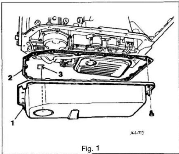


8.2
8.2.15 FLUID PAN, RENEW (6,0L)
SRO 44.24.04
- Open the hood and it a suitable fender cover.
■ Raise the vehicle on a ramp.
■ Slacken the underfloor catalyst to downpipe clamps securing bolts.
■Displace and reposition the olive clamps on the pipes.
■ Slacken the underfloor catalyst to intermediate silencer clamps securing bolts. - Displace the underfloor catalyst assembly rearwards to disconnect from the downpipes.
■ Displace and remove the olives from the downpipes.
■ Using a wire brush, clean the olives and downpipe joints. - Place a suitable piece of wood between the underfloor catalyst and the body for access.
- Drain the transmission lubrication system, see Sub–sec-tion 8.2.13.
- Release and remove thefluid pan securing bolts.
- Drain the residual fluid from the fluid pan.
■Remove the fluid pan (1 Fig. 1) and gasket (2 Fig. 1). - Clean the fluid pan gasket, which can be re-used if ingood condition.
■ Place the fluid pan gasket aside.
■ Remove the magnet (3Fig. 1) from the fluid pan.
■ Clean the magnet and place on a clean surface.
■ Clean the transmissionfluid pan joint face.
■ Clean the fluid pan.
■ Place the fluid pan aside.
■ Attach the magnet to the recess in a newfluid pan.
■ Fit and align a serviceable gasket to the fluid pan.
■ Fit the fluid pan and gasket to the transmission unit.
■ Fit and tighten thefluid pan securing bolts.
■ Remove the block of wood from between the underfloor catalyst and the floor.
■ Apply sealant to the downpipe joints and olives. See Service Materials in the preliminary pages, this Section.
■ Fit and seat the olives to the downpipes.
■ Reconnect the underfloor catalyst to the downpipes.
■ Reposition the olive clamps.
■ Tighten the underfloor catalyst to downpipe clamps securing bolts. - Align the intermediate silencer to the underfloor catalyst assembly.
■Tighten the clamp securing bolts.
■ Lower the vehicle on the ramp.
■ Refill the transmission unit with fluid, see Sub-section 8.2.13.
Remove the fender cover and close the hood.
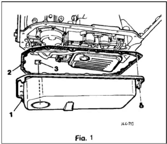

- Open the hood and fit a suitable fender cover.
■ Raise the vehicle on a ramp. - Drain the transmission lubrication system, see Sub–section 8.2.13.
■ Slacken the downpipe catalyst to intermediate catalyst clamp securing bolts.
■Slacken the intermediate catalyst to intermediate silencers clamp securing bolts.
■ Disconnect the intermediate catalyst pipe from the downpipe.
■ Clean the downpipe and intermediate pipe joint.
■ Release and remove the fluid pan securing bolts.
■ Remove fluid pan (1 Fig. 1) and gasket (2 Fig. 1).
■ Drain the residu fluid from the fluid pan.
■ Remove and discard the fluid pan gasket.
- Remove the magnet(3 Fig. 1) from the fluid pan; clean the magnet.
■ Place the magnet on a clean surface.
■ Clean the transmissidoid pan joint face.
■ Clean thfluid pan.
■ Place the fluid pan aside.
■ Attach the magnet to the recess in a new fluid pan.
■ Fit and align a new gasket to the fluid pan.
■ Fit the fluid pan and gasket to the transmission unit.
■ Fit and tighten theid pan securing bolts.
■ Apply sealato the intermediate pipe joint. See Service Materials inthe preliminary pages, this Section.
■ Reconnect the intermediate pipe to the downpipe.
■ Align the intermediate catalyst assembly.
■ Tighten the intermediate pipe to downpipe securing clamp.
■ Align the intermediate silencers to the intermediate catalyst assembly.
■lighten the intermediate silencer securing clamps.
■ Lower the vehicle on the ramp.
■ Refill the transmission unit with fluid, see Sub-section 8.2.13.
■ Remove the fender cover and close the hood.
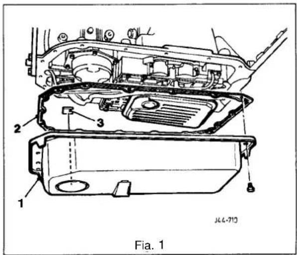


8.2
- Open the hood and fit a suitable fender cover.
■ Raise the vehicle on a ramp.
■ Slackenthe underfloor catalyst to downpipe clamp securing bolts.
■ Displace and reposition the olive clamps on the pipes.
■ Slacken the underfloor catalyst to intermediate silencer clamps securing bolts.
■ Displace the underfloor catalyst assembly rearwards to disconnect from the downpipes.
Displace and remove the olives from the downpipes.
■ Using a wire brush, clean the olives and downpipe joints.
■ Place a suitable piece of wood between the underfloor catalyst and the body for access. - Drain the transmission lubrication system, see Sub–sec-tion 8.2.13.
■ Release and remove the fluid pan securing bolts.
■ Remove the fluid pan(1 Fig. 1) and gasket (2 Fig. 1). - Drain the residual fluid from the fluid pan. Remove and discard the fluid pan gasket.
■ Remove the magnet(3 Fig. 1) from the fluid pan; clean the magnet.
■ Place the magnet on a clean surface.
■ Clean the fluid pan joint face.
■ Clean thefluid pan.
■ Place the fluid pan aside.
■ Attach the magnet to the recess in the fluid pan.
■ Fit and align a new gasket to the fluid pan.
■ Fit the fluid pan and gasket to the transmission unit.
■ Fit and tighten the fluid pan securing bolts.
■ Remove the block of wood from between the under floor catalyst and the floor.
■ Apply sealant to the downpipe joints and olives. See Service Materials in the preliminary pages, this Section. - Fit and seat the olives to the downpipes.
■ Reconnectthe underfloor catalyst to the downpipes.
■ Reposition the olive clamps.
■ Tighten the underfloor catalyst to downpipe clamps securing bolts. - Align the intermediate silencers to the underfloor catalyst assembly.
■ Tighten the clamp securing bolts.
■ Lower the vehicle on the ramp.
■ Refill the transmission unit with fluid, see Sub-section 8.2.13.
■ Remove the fender cover and close the hood.
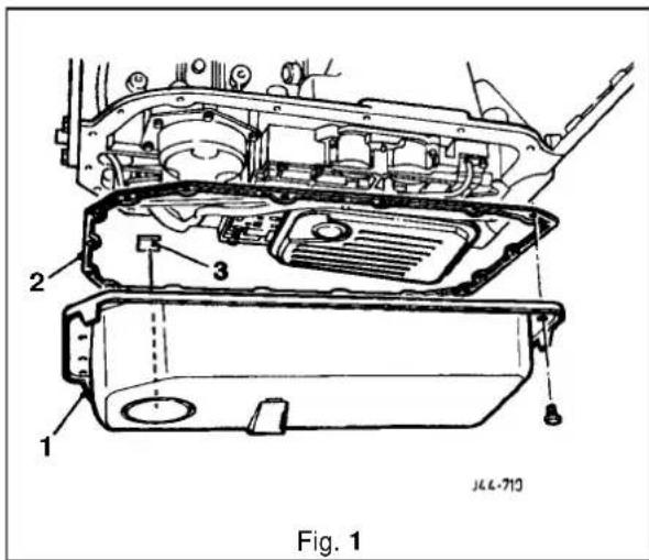
8.2.18 FLUID FILTER, RENEW(4,0L SCAND6,0L)
SRO 44.24.07
- Open the hood and fit a suitable fender cover.
■ Raise the vehicle on a ramp. - Drain the transmission lubrication system, see Sub-section 8.2.13.
■ Remove the fluid pan, see Sub-section 8.2.14 (4,0LSC) or Sub-section 8.2.15 (6,0L).
■ Displace and remove the filter (1 Fig. 1) from the transmission unit and place aside.
■ Fit and align a new filter to the transmission unit.
■ Refit the fluid pan, see Sub-section 8.2.14 (4,0L SC) or Sub-section 8.2.15 (6,0L).
■ Lower the vehicle on the ramp.
■ Refill the transmission unit with fluid, see Subsection 8.2.13. - Remove the fender cover and close the hood.
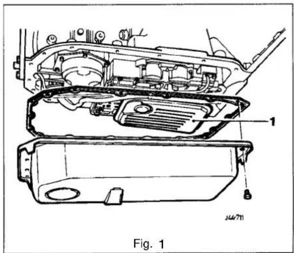
8.2
8.2.19 TRANSMISSION INTERNAL HARNESS MULTI-PIN SOCKET 'O' RING, RENEW (4,0L SC AND 6,0L)
SRO 44.24.20
- Open the hood and fit a suitable fender cover.
■ Raise the vehicle on a ramp. - Drain the transmission lubrication system, see Sub–sec-tion 8.2.13.
■ Remove the fluid pan, see Sub-section 8.2.14(4,0L SC) or Sub-section 8.2.15(6,0L). - Disconnect the external harness multi-pin plug from the internal harness multi-pin socket.
Note: The plug is secured to the socket by its captive locking ring.
- Release and removethe internal harness multi-pin socket to transmission casing securing nut.
- Displace the internal harness multi -pin socket from the transmission casing.
- Remove and discard the 'O ring seal (Fig.1) from the multi-pin socket.
■ Fit and seat a new'O' ring seal to the multi-pin socket.
■ Reposition and seat the internal harness multi-pin socket to the transmission casing.
- Fit and tighten the internal harness multi-pin socket to the transmission casing securing nut.
- Connect the external harness multi-pin plug to the internal harness multi-pin socket; the plug is secured by its captive locking ring.
■ Refit the fluid pan, see Sub-section 8.2.14 (4,0L SC) or Sub-section 8.2.15 (6,0L).
■ Lower the vehicle on the ramp.
■ Refill the transmission unit with fluid, see Sub-section 8.2.13.
■ Remove the fender cover and close the hood.


8.2.20 INTERNAL LUBRICATION PIPE, RENEW (4,0L SC AND 6,0L)
SRO 44.24.21
■ Open the hood and fit a suitable fender cover.
■ Raise the vehicle on a ramp.
- Drain the transmission lubrication system, see Sub–sec-tion 8.2.13.
■ Remove fluid pan, see Subsection 8.2.14(4,0L SC) or Sub-section 8.2.15 (6,0L).
■ Release and remove the internal lubrication pipe retainer to valve body securing bolt.
■ Remove the lubrication pipe retainer.
■ Release and remove the lubrication pipe clamp to valve body securing nut.
■ Remove the lubrication pipe clamp.
■ Displace and remove the lubrication pipe from the transmission unit.
- Drain any residual fluid from the lubrication pipe and place the pipe aside.
■ Clean the relevant parts.
- Fitandfullyseata newlubricationpipetothetransmission unit.
■ Fit the lubrication pipe clamp.
■ Fit and tighten the lubrication pipeclamptovalve body securing bolt.
■ Fit the lubrication pipe retainer.
■ Refit theluid pan, see Sub-section 8.2.14 (4,0L SC) or Subsection 8.2.15 (6,0L).
■ Lower the vehicle on the ramp.
- Refill the transmission unit with fluid, see Sub-section 8.2.13.
■ Remove the fender cover and close the hood.

8.2


8.2.21 INTERNAL DIPSTICK STOP, RENEW (4,0L SC AND 6,0L)
SRO 44.24.22
- Open the hood and fit a suitable fender cover.
- Raise the vehicle on a ramp.
- Drain the transmission lubrication system, see Sub–section 8.2.13.
- Remove the fluid pan, see Sub-section 8.2.14 (4,0L SC) or Sub-section 8.2.15 (6,0L).
- Release and remove the dipstick stop to valve body securing bolts.
■ Reposition the internal harness securing clip.
■ Remove the dipstick stop.
■ Clean all relevant parts. - Place the dipstick stop aside.
- Fit a new dipstick stop to the valve body.
■ Reposition and align the internal harness securing clip. - Fit and tighten the dipstick stop to valve body securing bolts.
- Refit the fluid pan, see Sub-section 8.2.14 (4,0L SC) or Sub-section 8.2.15 (6,0L).
- Refit the downpipe to underfloor catalyst olives.
■ Lower the vehicle on the ramp. - Refill the transmission unit with fluid, see Sub-section 8.2.13.
■ Remove the fender cover and close the hood.

8.2.22 MANUAL DETENT SPRING, RENEW (4,0L SC AND 6,0L)
SRO 44.26.10
- Open the hood and fit a suitable fender cover.
■ Raise the vehicle on a ramp. - Drain the transmission lubrication system, see Sub–sec-tion 8.2.13.
■ Remove the fluid pan, see Subsection 8.2.14 (4,0L SC) or Sub-section 8.2.15 (6,0L).
■ Remove the fluid filter, see Subsection 8.2.18.
■ Select 'P' (Park) and ensure that the pawl is engaged. - Release and remove the manual valve detent spring and roller assembly to valve body securing bolts.
■ Remove the detent spring assembly and place aside.
■ Clean the relevant parts. - Fit a new detent spring assembly to the valve body.
- Fit but do not fully tighten the detent spring assembly to the valve body securing bolts.
- Align the detent spring to centralize the roller with the detent lever in the 'P' (Park) position.
- Check that in 'N' (Neutral), the shift lever is properly in position. It is essential that the detent spring within the transmission unit dictates to the shift lever and not the other way around.
Finally tighten the detent spring assembly to valve body securing bolts.
■ Refit the fluid filter, see Subsection 8.2.18. - Refit the fluid pan, see Subsection 8.2.14 (4,0L SC) or Sub-section 8.2.15 (6,0L).
■ Lower the vehicle on the ramp.
■ Refill the transmission unit with fluid, see Subsection 8.2.13.
■ Remove the fender cover and close the hood.

8.2


SECTION CONTENTS
Sub-Section Title
SRO
Page
i to iv ...... Preliminary Pages .... itov
9.1 Major Component Description 1
9.2 Drive Shaft. Align 47.15.51 2
9.3 ...... Final Drive Unit Output Shaft End Float. Check .... 51.10.24 .... 4
9.4 ...... Final Drive Unit Output Shaft Housing 'O' Ring. Renew ....51.20.19 ....4
9.5 ...... Final Drive Unit Oil Seal Pinion Flange. Renew .... 51.20.01 .... 4
9.6 ...... Final Drive Unit Output Shaft Bearing. Renew ...... 51.10.22 ...... 5
9.7 ...... Final Drive Unit Output Shaft Oil Seal, Renew .... 51.20.04 .... 5
9.8 ...... Final Drive Unit. Renew ...... 51.25.13 ...... 6
9.9. ...... Axle Shaft Assembly, Renew ...... 47.10.01 ...... 7
9.10 Rear Hub Bearing. Renew 64.15.14 8
9.11 ....Rear Hub Oil Seal Renew .... 64.15.15 ....8


- SERVICE TOOLS & EQUIPMENT
| Illustration | Jaguar Number | Description | Notes | |
 | JD 1D | Hub remover | ||
 | JD 1D / 7 | Thread protector | ||
 | JD 13B | Dial test indicator (DTI) and locator | ||
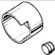 | JD 132 - 1 | Hub press tool and button | ||
 | JD 156 | Pinion puller | ||
| not illustrated | JD 198 | Pinion Oil seal installer | ||
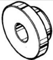 | JD 550 - 1 | Output shaft oilseal remove/ replace | ||
 | JD 550 - 4 / 1 & 4 / 2 | Adaptor / replacer bearing and E | ||
 | SL 7 | Bearing replacer | ||
| illustration | Jaguar Number | Description | Notes | |
 | 18G 134 | Driver Handle | ||
| Pinion flange wrench | ||||
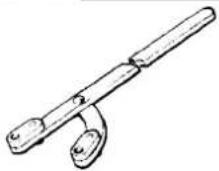 | 18G 1205 | Pinion flange wrench | ||
II. TORQUE TIGHTENING SPECIFICATIONS
| Fixing | Tightening Torque (Nm) |
| 'A' frame to differential | 85 - 115 |
| 'A' frame to wide mountina bracket | 72 - 98 |
| ABS sensor to hub carrier | 8 - 10 |
| Axle shaft hub nut * See repair operations 47.10.01 and64.15.14 & 15 this section | 304 - 336 * |
| Axle shaft to output flange | 81 - 99 |
| Bush, 'A' frame lower mounting to body | 80 - 100 |
| Centre drive shaft bearing to crossmember | 19 - 27 |
| Crossmember to bodv | 19 - 27 |
| Differential nose to wide mounting bracket | 34 - 46 |
| Differential strut to bodv | 85 - 95 |
| Drive shaft to auto-gearbox flange | 33 - 45 |
| Drive shaft flexible coupling to pinion flange | 71 - 83 |
| Exhaust joint 'Olive' | 14 - 18 |
| Exhaust joint 'Torca clamp' | 60 - 80 |
| Exhaust mounting to wide mounting bracket | 22 - 88 |
| Final drive unit to wide mounting bracket at differential 'nose' | 34 - 46 |
| Hub carrier fulcrum | 80 - 100 |
| Lower shock absorber bolt | 80 - 100 |
| Mounting bracket ('A' frame) to body (inner) | 40 - 50 |
| Mountina bracket ('A' frame) to bodv (outer) | 80 - 100 |
| Oil drain plug | 26 - 34 |
| Oil filler plua | 20 - 26 |
| Output shaft housing to differential case | 52 - 58 |
| Pendulum assembly to differential | 160 - 200 |
| Pinion drive flange nut * See repair operation 5120.01 this section | Minimum 135 * |
| Rear mounting bracket to differential | 85 - 105 |
| Road wheel-Alloy | 88 - 102 |
| Road wheel - Steel | 68 - 82 |
| Upper link to differential | 72 - 98 |
| Upper link to wide mounting bracket & 'A' frame | 85 - 115 |
| Wide mounting bracket to 'A' frame | 85 - 115 |
| Wishbone pivot nut | 80 - 100 |
| Wishbone tie to differential stud | 85 - 105 |
| Description | Uses | Notes |
| Loctite 270 Adhesive | Axle shaft spline | 30 / 50% radial coverage |
| Hylosil 102- Sealant | Output shaft bearing housing to differential case | |
| Retinax A grease | Rear hub bearings and seal pre-lubrication | See Sub SectionIV Service Data |
IV. SERVICE DATA
| Specification | |
| = 0.32minus 0.08 = 3.07 mm (required adjustable spacer)Minimum specified pre-load □ 0.025, therefore 3.15 minus 0.025 = 3.125 mm (required adjustable spacer).Adjustable spacers are available in 0,05 mm increments from 2,22 to 3,47 mm. | 0,025 to 0,08 mm |
| Rear hub bearing grease- Quantity | Inner bearing race1 1,5ml. Outer bearing race9,0 ml |
| Final drive unit pinion spigot radial run-out | Must not exceed 0,08 mm TIR (total indicator reading).Should therun-out exceed the stated limit, renew the final drive unit. |


9.1 MAJOR COMPONENT DESCRIPTION
Power is transmitted from the gearbox to the final drive unit via a two piece drive shaft (formerly known as 'propeller shaft') which is supported by a center bearing. Isolation from vibration and transmitted harshness is suppressed by rubber mounting of both the center bearing and the connection of the drive shaft to differential drive flange.
The hypoid final drive assembly is available with either a conventional, or a limited slip differential.
The limited slip, 'Powr-LoK unit may be identified by either a tag carrying the legend'PL' or a label with an 'X', both to be found on the rear cover.
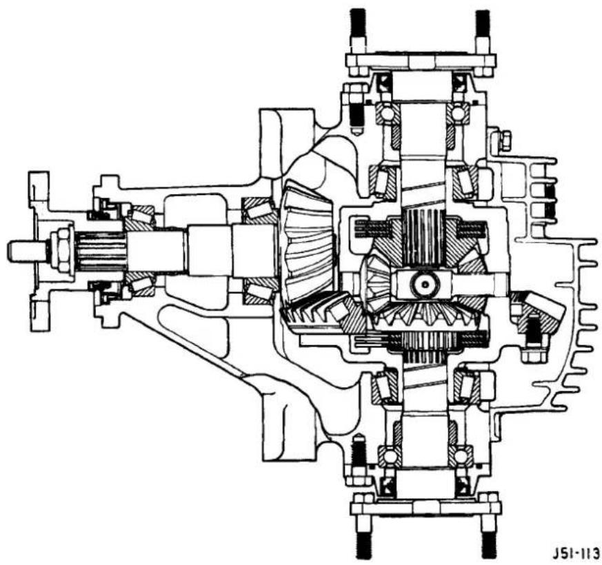
Fig. 1 sectional view of 'Powr-Lok' unit.
Forged axle shafts (formerly known as 'drive shaft') transmit drive from the differential to the rear wheels, each shaft having two universal joints. The axle shaft acts as an upper suspension link and controls static wheel camber by insertion of appropriate shims between the final drive unit and axle shaft inner flanges. Each axle shaft is supported at the outer end by preloaded taper roller bearings housed in a cast aluminium hub carrier.
9.2 DRIVE SHAFT, ALIGN
SRO 47.15.51
CAUTION: To preserve 'drive line' refinement, individual parts, other than fixings, MUST NOT be renewed. In the event of any balance or drive shaft component related problem, the complete assembly must be renewed. Under no circumstances must the flexible coupling (or its fixings) be loosened or removed from the drive shaft flange.
Preliminary Checks
Before this procedure is actioned it is advisable to ensure that:
The gearbox mounting center stud is positioned centrally in relation to the crossmember inspection hole.
The crossmember is central on the body fixings and not 'hard over' to one side.
The differential spigot radialrun-out is within specification, see preliminary pages.
If the vehicle has been standing for a period the tires may be 'flatspotted'. If so, this will clear in approximate.; 400 km (250 miles). After this distance the source of vibration should be reassessed.
12 Cylinder
■ Remove exhaust center section.
All
- Locate suitable 'plumb lines' over drive shaft outside diameter, but NOT over any balance weight or weld:
- Front section - behind gearbox output coupling, 12,7 mm (0.5 in) diameter weight (1 Fig. 1).
- Rear section - immediately behind center bearing(2 Fig. 1).
- Rear section - in front of differential flange (3Fig. 1)
Note: It is essential that the front weight should be as specified so that the different diameters of the two shafts may be taken into account.
Method 1
- Viewed from the rear with the rear 'plumb line' coincidental with the outside diameter of the front weight, the center 'plumb line' should align with the rear 'plumb line' (4 Fig. 1).
- To re-align the center bearing, slacken bearing fixings and position to suit.
- Tighten all fixings to specification ensuring that the 'anti-twist' plate is allowed to freely align before the center bearing fixings are secured.

Method 2
A refinement to Method1 may be made by stretching a line horizontally along the center line of the vehicle to touch the outside diameter of the front weight and the rear 'plumb line'. Take care not to bias the vertical lines with the horizontal line.
■ Set the center 'plumb line' to touch the horizontal line by movement of the center bearing (Fig. 1).
- To realign the center bearing, slacken bearing fixings and position to suit.
- Tighten all fixings to specification ensuring that the 'anti-twist' plate is allowed to freely align before the center bearing fixings are secured.

Recommended locally made tools
Plumb line Locally made
Weight Locally made 127 mm (0,5 in) diameter mild steel


9

9.3 OUTPUT SHAFT END FLOAT, CHECK
SRO 51.10.24
- Disconnect vehicle battery ground lead.
■ Support the vehicle at the rear.
Mount a dial test indicator (DTI) to the differential housing with the probe resting on the output shaft flange (DTI probe must be parallel to the output shaft center line and NOT at an angle).
■ Push the wheel/ shaft assembly inwards and zero the DTI; pull outwards and note the reading.
- If the end float exceeds 0.15 mm; firstly verify the shim preload and if this is found to be correct, renew the output shaft bearing. See 51.10.22. this section, for shim check and renew operations.
9.4 OUTPUT SHAFT HOUSING 'O' RING, RENEW
SRO 51.20.19
■ Disconnect vehicle battery ground lead.
- Prior to removal of shaft assembly check output shaft end float in accordance with operation 51.10.24.
• See operation 51.10.22. this section, for process detail, less bearing / oil seal renew.
9.5 OIL SEAL - PINION FLANGE, RENEW
SRO 51.20.01
■ Disconnect vehicle battery ground lead.
■ Support the vehicle at the rear.
■ Disconnect main handbrake cable at compensator.
- 'Match mark' the FLEXIBLE COUPLING to the differential DRIVE FLANGE and remove fixings.
Remove fixings center bearing to crossmember and push drive shaft rear section forward to disengage from pinion spigot.
CAUTION: Under no circumstances must the flexible coupling (or its fixings) be loosened or removed from the drive shaft flange.
Support the drive shaft, do not allow it to hang.
- 'Match mark' the drive flange retaining nut to both the pinion and the drive flange (Fig. 1).
- Slacken the flange retainingnut approximately half aturn and retighten to the 'match mark' noting the required force. If the force does NOT exceed 135 Nm, the final drive unit MUST be replaced.
■ Remove the retaining nut, washer and drive flange.
CAUTION: Use only special tools; 18G 1205 to restrict rotation and JD 156 to remove drive flange.
- Inspect the drive flange oil seal surface for damage corrosion or grooving and replace as necessary.
Do not use abrasive cloth, or paper, to remove imperfections from the seal surface.
■ Remove oil seal from differential case taking care not to damage the machined counterbore.
■ Clean seal counterbore.
■ Using special tool JD 198 fit replacement oil seal to differential case ensuring that, seal is square, fully seated and the lip spring is not dislodged.
Apply grease to drive flange seal diameter and refit the flange to the pinion in the original position.
Note: Do not hammer the drive flange onto the pinion; pull down with the drive flange nut.
Tighten the drive flange nut to the original noted torque PLUS 10%.
- Check that the pinion spigot radial run-out is to specification.
Fitting and reassembly is the reversal of this procedure ensuring that drive shaft fixings are renewed and that the shaft is aligned in accordance with Sub-Section 9.2.
Correct the final drive oil level if required.
■ Tighten all fixings to specification.
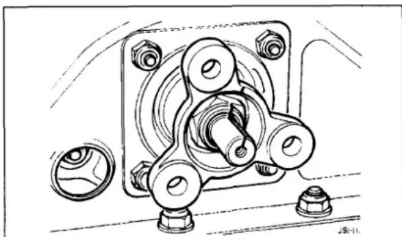
Fig. 1
9.6 OUTPUT SHAFT BEARING, RENEW
SRO 51.10.22
9.7 OUTPUT SHAFT OIL SEAL, RENEW
SRO 51.20.04
■ Disconnect vehicle battery ground lead.
■ Support the vehicle at the rear and remove the rear road wheel (or wheels).
- 'Match mark' the axle shaft flange to the output shaft flange and remove fixings, note camber shim.
■ Thoroughly clean the area around the output shaft housing and differential case.
■ Release fixings and remove output shaft assembly, discard 'O' ring.
■ Mark bearing retaining collar axially and drill 3 off holes 4,0 mm diameter equally spaced, to a MAXIMUM depth of 5,0 mm (1 Fig. 1).
■With a suitable chisel(2 Fig. 1) strike the collar across the three drilled holes to relieve tension within the steel.
CAUTION: Do not drill into the output shaft, it is not necessary to break the inside diameter of the collar. There is no need to split the collar when chiselling.
- Using a suitable press, remove bearing and collar, remove the oil seal and discard it along with bearing.
CAUTION: The original bearing must NOT be cleaned and reused; always renew it.
Inspect the output shaft oil seal surface for damage corrosion or grooving and replace as necessary.
Note: Do not use abrasive cloth or paper to remove imperfections from the seal surface
■ Using special tools JD 550-1 and 18G 134, assemble new oil seal to housing, ensuring that the seal top face is 1.8 mm below the housing top face and NOT down on the counterbore face.
- Lubricate the output shaft seal diameter and oil seal lip and position the housing assembly to the shaft.
- Using special tool SL7 and a suitable press, assemble bearing to output shaft.
■ Using special tool SL7 and a suitable press, assemble retaining collar to output shaft.
- Fitthe original shims and using hand pressure only to seat the assembly, check that the clearance between the output shaft housing and differential case is in the range 0,05 to 0,13 mm. Shim to suit if not in this range.
■ Using a new 'O' ring and sealant on the mating faces, assemble the output shaft assembly to the differential case. See Sub-Section 9.3 Output Shaft End Float Check.
■ Fitting and reassembly is the reversal of this procedure ensuring that all fixings are tightened to specification and new locking nuts are used.
Correct the final drive oil level if required.

Fig. 1


9
9.8 FINAL DRIVE UNIT, RENEW
SRO 51.25.13
■ Disconnect vehicle battery ground lead.
■ Support the vehicle at the rear and remove the rear road wheels.
- Disconnect brake pad wear sensor multi –plug at RH hub carrier and remove tie straps from wishbone. Release ABS speed sensors at RH and LH hub carriers and remove tie straps from wishbones.
■ Remove rear brake calipers, see Section 12, and support at bump stop. Disconnect main handbrake cable at compensator, short cables at joining piece and remove compensator.
■ Remove fixings, FLEXIBLE coupling to differential DRIVE FLANGE.
CAUTION: Under no circumstances must the flexible coupling (or its fixings) be loosened or removed from the driveshaft flange.
■ Remove fixings center bearing to crossmember (1Fig. 1) and push drive shaft rear section forward to disengage from pinion spigot.

Note: Take account of any shims located between the center bearing and the crossmember.
■ Release fixings and remove, over axle exhaust pipe mounting from wide mounting bracket.
■ Support the rear suspension assembly from below and remove fixings from RHand LHsides inthe following order:
-
Shock absorber to body upper fixings.
-
Differential strut to body(1 Fig. 2).
-
'A' frame bush (2 Fig. 2).
-
Lower mounting bracket assembly to body (3Fig. 2).
■ Carefully lower the unit clear of the vehicle and place in a safe working location.
■ Release handbrake cable to wide mounting bracket clips.
■ Disconnect RH and LH axle shafts from differential couplings, note camber shim and discard fixings.
■ Remove wishbone pivot bolt, washers and remove wisbone / hub / axle shaft assembly RH and LH.
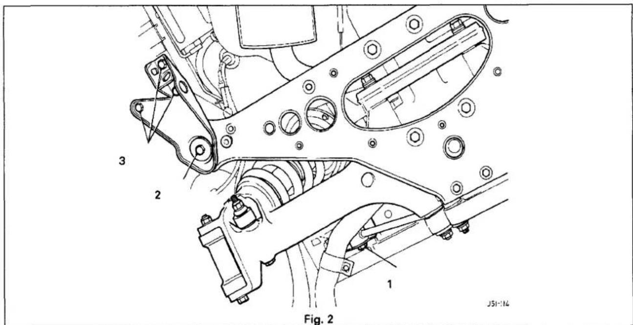

■ Remove upper link assembly from differential and wide mounting bracket/'A' frame.
■ Release fixings, 'A' frame to differential, 'A' frame to wishbone tie and wide mounting bracket to 'A' frame.
■ Remove wishbone tie assembly, rear mounting bracket and pendulum assembly.
■ Release fixings differential nose to wide mounting bracket.
■ Assembly and fitting is the reversal of this procedure, taking note of the following:
Drive shaft must be aligned in accordance with Sub-Section 9.2.
Renew all self locking nuts.
Renew all bolts that were originally fitted with thread locking adhesive.
Replace all locking wire and split pins (cotter pins).
Tighten all fixings to the specified torque.
Correct the final drive oil level if required.
Check and adjust rear wheel camber setting as required.
9.9 AXLE SHAFT ASSEMBLY, RENEW
SRO 47.10.01
■ Disconnect vehicle battery ground lead.
■ Slacken appropriate axle shaft hub nut.
■ Support the vehicle at the rear and remove rear road wheel.
■ Remove brake caliper in accordance with 70.55.03. Section 12, but do not disconnect hydraulics.
■ Slacken hub carrier fulcrum and remove ABS sensor from hub carrier.
■ Remove axle shaft hub nut and collar.
■ Remove fixings axle shaft to differential output shaft flange, note camber shim.
■ With service tools JD1D/7 (Fig. 1) and JD1D (Fig. 2), push shaft through hub.
■ Remove axle shaft assembly.
CAUTION: Take care not to introduce debris into the hub bearings, or damage seal.
- Prior to assembly, remove all traces of adhesive from hub splines.
■ Assembly and fitting is the reversal of this procedure taking note of the following:
Adhesive should be applied to axle shaft splines over a radial area of 30 to 50%.
Renew all bolts that were originally fitted with thread locking adhesive.
Replace all locking wire and split pins (cotter pins).
Tighten all fixings to the specified torque.
Check and adjust rear wheel camber setting.
Verify operation of brakes.
Renew all self locking nuts.
Note: The axle shaft nut is a self-bcking item with a thread insert and must NOT be re-used.


9.10 REAR HUB BEARING, RENEW
SRO 64.15.14
9.11 REAR HUB OIL SEAL, RENEW
SRO 64.15.15
Removal
■ Disconnect vehicle battery ground lead.
■ Slacken appropriate axle shaft hub nut.
■ Support the vehicle at the rear and remove rear road wheel.
Note: To aid assembly, mark the position of the head of the hub carrier fulcrum, relative to the wishbone slot.
■ Disconnect handbrake cable inner and outer.
■ Remove brake caliper in accordance with Section 12, but do not disconnect hydraulics.
■ Slacken hub carrier fulcrum and remove ABS sensor from hub carrier.
■ Remove axle shaft hub nut (and discard), collar and hub carrier fulcrum.
■ Using service tools JD 1D / 7 and JD I D (Fig. 1), push shaft through hub and pull the hub carrier assembly clear.
■ Using Hub tool JD 132-1 (1 Fig. 2) and a suitable press, align the hub assembly to the tool ensuring the hand brake expander locates into the tool cut out.
- Locate button JD 132 - 2 and press the hub from the carrier.
■ Remove the outer bearing race and seal from either the hub or the carrier and place the ABS rotor to one side.
■ Remove from the carrier; bearing spacer, adjustable spacer, inner race and seal.
Renew Bearings/ Seal(s)
■ Using a suitable drift remove the inner and outer bearing cups.
■ Clean all components paying particular attention to the removal of all traces of locking compound from the hub AND axle shaft splines.
■ Using service tools J\$50 - 4/2, 4/1 and 18G 134fit new cups to the hub carrier ensuring that they are 'square'and fully seated.
■ Fit the new outer bearing raceto the hub.
Note: Do notfit seals or 'pack' bearing at this point.
■ Assemble the hub and race to the carrier along with bearing spacer (noting orientation) and the largest available adjustable spacer, i.e. 3.47 mm.
■ Fit the new inner bearing and ABS rotor to the hub.
■ Apply a compressive load to the hub/bearing assembly, using a press, vice or long bolt. Ensure that the force that the axle shaft fixing would normally provide is not exceeded.
■ Measure the hub end-float, using service tool JD 13B dial test indicator (DTI).
■ Using the indicated endfloat dimension, select a suitable adjustable spacer to give the specified pre-load.
Note: See Service Data, (preliminary pages) for pre-load specification and typical example.
■ Remove the outer bearing from the hub.
■ Lubricate the bearings as specified.
- Locate the outer bearing to the hub carrier assembly.

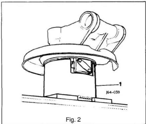


- Using service tools JD 550 – 4 / 2, 4 / 1 and 18G 134, fit new seal to the hub carrier ensuring that it is 'square' and fully seated.
- Invert the assembly and locate the bearing spacer (noting orientation) and selected adjustable spacer over the hub.
- Assemble the inner bearing race and locate the inner seal using service tools JD 550 - 4/2, 4/1 and 18G 134, ensuring that the seal is 'square' and fully seated.
- Press the ABS rotor into position.
- Assembly and fitting is the reversal of this procedure taking note of the following:
Adhesive should be applied to axle shaft splines over a radial area of 30 to 50%.
For the initial setting, position the head of the hub carrier fulcrum to the mark previously made on the wishbone prior to checking and adjusting (if required) rear wheel toe-in.
Renew all bolts that were originally fitted with thread locking adhesive.
Replace all locking wire and split pins (cotter pins).
Tighten all fixings to the specified torque.
Verify operation of brakes.
Renew all self locking nuts.
Note: The axle shaft nut is a self-locking item with a thread insert and must NOT be re-used.

- Axle shaft
- Bearing spacer
- Adjustable spacer
- Inner bearing
5 Inner seal
6 Outer bearing
7 Outer seal
8 ABS rotor
9. Hub
10. Axle shaft nut
11. Hub carrier
Fig. 1 Sectional view Hub assembly

SECTION CONTENTS
| Sub-Section | Title | SRO | Page |
| i to iii | Preliminary Pages | i Toiv | |
| 10.1 | Steering System Description | 1 | |
| 10.1.1 | Steering System Description. Steering Column Major Components | 1 | |
| 10.1.2 | Steering System Description. Steering Column Operating Principle | 1 | |
| 10.1.3 | Steering System Description. Hydraulic System Major Components | 2 | |
| 10.1.4 | Steering System Description. Hydraulic System Features | 2 | |
| 10.1.5 | Steering System Description. Hydraulic System Operating Principle | 2 | |
| 10.2 | Service ProceduresSafety Related | 5 | |
| 10.2.1 | ServiceProcedures-Safety Related.Airbag | 5 | |
| 10.3 | Service Procedures | 5 | |
| 10.3.1 | Service Procedures Working Practices | 5 | |
| 10.3.2 | Service Procedures Working Practices. Fluid Level Check & Top-up | 5 | |
| 10.3.3 | Service Procedures Working Practices. System Bleed | 5 | |
| 10.3.4 | Service Procedures Working Practices. Fluid Reservoir | 5 | |
| 10.3.5 | Service Procedures Working Practices. Hydraulic Connections | 5 | |
| 10.4 | Diagnostic Procedure | 6 | |
| 10.4.1 | Diagnostic Procedure. introduction | 6 | |
| 10.4.2 | Diagnostic Procedure. Preliminary Action | 6 | |
| 10.4.3 | Diagnostic Chart 1 | 6 | |
| 10.4.4 | Diagnostic Chart 2 | 7 | |
| 10.4.5 | Diagnostic Chart3 | 8 | |
| 10.5 | Outer Track Rod Ball Joint. Renew | 57.55.02 | 9 |
| 10.6 | Front Hub Assembly, Renew | 60.25.01 | 9 |
| 10.7 | Front Hub Bearing End Float. Check & Adjust | 60.25.12 | 9 |
| 10.8 | Front Hub Bearing. Renew | 60.25.16 | 9 |
| 10.9 | Front Hub Oil Seal. Renew | 60.25.17 | 9 |


I. SERVICE TOOLS & EQUIPMENT
| Illustration Jaguar | Number | Description | Notes |
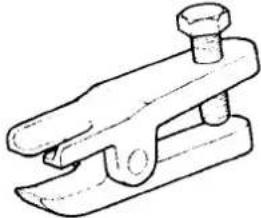 | JD 100 | Ball joint separator | |
 | 18G-134 | Handle | |
 | JD550-5 / 1& 2 | Adaptor | |
 | JD-179 | Seal replacer |
II. TORQUE TIGHTENING SPECIFICATIONS
| Fixing Tightening | Torque (Nm) |
| Air bag to steering wheel | 4 - 5 |
| Blanking plug for rack centralizing pin | 7 - 10 |
| Fluid pipe to pump banjo bolt | 34 - 46 |
| Fluid pipe to cooler sleeve nut X 2 | 17 - 23 |
| Fluid pressure pipe pump to rack mid connector | 17 - 23 |
| Heatshield to rack(12 cylinder) | 22 - 28 |
| Horn bar (at steering wheel) | 5 - 7 |
| Hose fromfluid reservoir (worm drive) | 25 - 3,5Retighten to nominal after30 minutes |
| Hoseto pump (worm drive) | 25 - 3,5Retighten to nominal after30 minutes |
| Hoseto fluid reservoir from cooler (worm drive) | 25 - 3,5Retighten to nominal after30 minutes |
| Lower column to steerina rack pinion | 22 - 28 |
| Pressure switch to feed pipe 12 cylinder only | 85 - 11,5 |
| Road wheel- Alloy | 88 - 102 |
| Road wheel- Steel | 68 - 82 |
| Steering column outer tube to body | 17 - 23 |
| Steering column universal joint to lower column | 17 - 23 |
| Steering column upper bracket to column outer tube | 16 - 20 |
| Steering column upper bracket to plenum stiffener | 17 - 23 |
| Steering column uppercowls | 2.5 - 3.5 |
| Steering rack to crossmember12 cylinder | 39 - 51 |
| Steering rack to crossmember6 cylinder | 43 - 57 |
| Steering wheel to column | 34 - 46 |
| Tie strap plenum | 16 - 20 |
| Track rod end taper balpinto steering arm | 59 - 71 |
| Track rod end lock nut | 51 - 69 |
| Tube nut- fluidpipe at steering rack2 off | 17 - 23 |
II. SERVICE MATERIALS
| Description | Uses | Notes |
| Retinax A grease | Front hub bearings and seals | See Sub Section IV Service Data |
| Power steering hydraulic fluid | Dexron 2E ATF minimum (or equivalent) | See Sub Section IV Service Data |
| Application | Specification |
| Front hub end-float | 0,025 to 0,08 mm |
| Front hub bearing grease- Quantity | 4 ml in each race |
| Toe-in 12 cylinder | 0° 5' + or - 10' underside of front crossbeam 143mm from ground level |
| Toe-in 6 cylinder | 0° 5' + or - 10' underside of front crossbeam 153mm from ground level |
| Steering system capacity | Approx 1liter from dry |
| Steering system operating pressure | 100> 110 bar |
| Steering system level checking frequency | 16,000 km |
| Steering rack turns lock to lock | 2,83 |
| Drive belt tension (12 cylinder only) | Burroughs method - New belt 790 N; If tension falls below 270 N reset at 630 NClavis method - New belt 114 to 120Hz; Iftension falls below 70 Hz reset at 87 to 93HzFor new belt, rotate engine 3 revolutions minimum and retention |
| Drive belt tension measuring point | Mid-way between crankshaft and compressor pulley |
10.1 STEERING SYSTEM DESCRIPTION
10.1.1 Steering Column Major Components
Integratedcolumn assembly incorporating power, or manual, reach/tilt mechanism and lock.
Ignition switch.
Ignition interlock solenoid.
Key transponder coil.
Body attachment points.
Depending upon model, the steering column may be adjusted for tilt and reach, either by electrical or manual means. Power variants may be either automatically or manually adjusted and all types have the entry/ exit feature.
10.1.2 Steering Column Operating Principle
Power Adjust: Two independent motor/ gearbox assemblies provide infinite adjustment for reach and height within approximate ranges of 35mm and 13° respectively. Adjustments may be automatically made in conjunction with the seat memory facility or manually when the adjustment switch is used. It should be noted that selection of 'Off will disable the automatic entry/ exit mode.
Manual Adjust: The cable operated reach adjustment is infinite within a range of 35mm, with the desired position being fixed by a rack and wedge. Tilt variations are stepped at approximately 3 G intervals with 6 positions being available, the uppermost being unlatched.
From the uppermost position the column may be pulled down to engage the first detent without using the tilt lever.
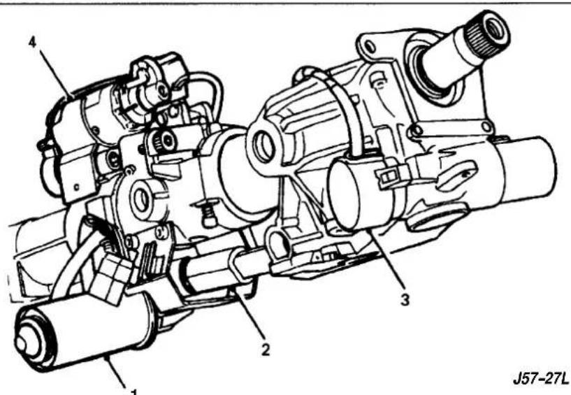
1 Tilt motor
3 Ignition switch
2 Tilt motor flexible coupling
4 Reach motor
Fig. 1 Major components Power operated steering column
WARNING: MANUAL ADJUST ONLY: TO AVOID PERSONAL INJURY, COLUMN UPWARD TRAVEL SHOULD BE MANUALLY RESTRAINED TO CHECK UPWARD SPRING ASSISTANCE. THIS IS ESPECIALLY IMPORTANT IF THE STEERING WHEEL HAS BEEN REMOVED FOR MAINTENANCE REASONS.
WARNING: ALL TYPES; DO NOT REMOVE THE STEERING COLUMN FROM THE VEHICLE WITH THE STEERING WHEEL ATTACHED UNLESS THE STEERING CENTERED AND THE COLUMN LOCK ISENGAGED. IF THE LOCK IS TO BE RENEWED, 'LOCK -WIRE THE ASSEMBLY TO PREVENT ROTATION. FAILURE TO OBSERVE THIS MAY RESULT IN AN INOPERATIVE AIRBAG SYSTEM. SEE LABEL ON STEERING WHEEL HUB.
10.1.3 Steering Hydraulic System Major Components
Engine driven rotary vane pump (belt driven 12 cylinder; direct drive from timing gear 6 cylinder) with falling flow characteristic (aspump speed increases fluid flow decreases) and integral pressure relief valve.
Remote fluid reservoir with integral 'return' side filter.
Steering rack (incorporating speed sensitive transducer).
Steering control module(SCM).
Fluidcooler integral with engine coolant radiator and associated pipe-work.
10.1.4 Hydraulic System Features
The 'Servotronic' system reduces steering input loads during parking and low speed manoeuvres and progressively increases input loads as vehicle speed rises. This feature enhances steering feel.
10.1.5 Hydraulic System Operating Principle (see illustrations on next three pages)
Rotary motion of the steering wheel is converted, via the steering gear pinion to lateral motion of the rack. Hydraulic assistance is provided by pressurized fluid being directed against the rack bar piston in the rack cylinder. The pressure applied to each side of the rack piston is controlled by the pinion valve which varies the restriction through which the flow for each side of the rack piston must pass.
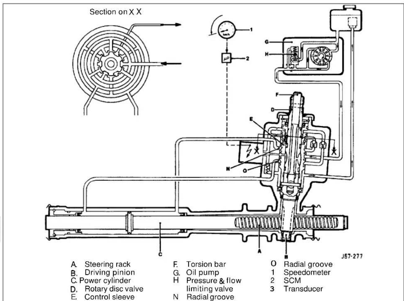
Fig. 1 Major components & hydraulic flow - Neutral position

With the vehicle travelling straight ahead, the valve restrictions are balanced, thus providing equal pressure on each side of the piston. When load is applied at the steering wheel the two halves of the pinion valve are displaced making the restrictions unequal. The differential pressure then directs the rack piston in favour of the higher pressure. As the turning load is removed the pressures equalize and the steering returns to the straight ahead position, aided by suspension geometry.
The displacement of the halves of the pinion valve (rotor and sleeve) is controlled by the elastic deformation of the torsion bar which is concentric with the pinion and valve.

J Outlet
K Outlet
L Inlet
M Inlet
N Radial groove (return)
0 Radial groove (feed)
P Feedgroove
Q Axial groove
R Axial groove
S Return groove
Fig.1 Porting & hydraulic flow - LOW speed clockwise rotation
The rotary valve within the pinion housing on the 'Servotronic'system is fitted with a 'Hydraulic Reaction Piston' (HRP). The HRP moves axially, relative to the rotor, on ball bearing travellers (acting as a face cam) and is connected to the sleeve by a four bearing helical screw. Pressure applied either side of the HRP is translated into a rotational force which resists torsion bar/valve displacement thus increasing steering effort. The amount of pressure applied to the HRP is controlled by: a) the differential pressure on the rack piston, proportional to vehicle cornering force and b) the position of the transducer valve controlled by the SCM from information gathered on road speed. Roadspeed data is processed from the left hand rear wheel speed sensor.

10.2 SERVICE PROCEDURES - SAFETY RELATED
10.2.1 Airbag
The electrically activated driver's side airbag is attached to the steering wheel hub and is fed by two wires from the column stalk assembly. Electrical input to the column stalk assembly for the airbag is provided by a dedicated harness which is encased in a yellow sleeve. A mechanism in the stalk assembly called the 'cable reel cassette' provides continuity from the static column to the steering wheel. The 'cable reel cassette' is driven by a tang which locates in the steering wheel. Because the connection is by wires, and the cassette assembly is only capable of approximately five (5) full turns, it is critically important that initial positioning is correct, see Section 15.
It is equally important that fitting of the steering wheel, connection of the column, lower shaft and steering rack should ONLY be made with the steering rack in the center of its travel.
WARNING: DO NOT REMOVE THE STEERING COLUMN FROM THE VEHICLE WITH THE STEERING WHEEL ATTACHED UNLESS THE STEERING IS CENTERED AND THE COLUMN LOCK IS ENGAGED. IF THE LOCK BARREL IS TO BE RENEWED, 'LOCK-WIRE THE ASSEMBLY TO PREVENT ROTATION. FAILURE TO OBSERVE THIS AND CONSEQUENT DAMAGE TO THE CABLE REEL CASSETTE MAY RESULT IN AN INOPERATIVE AIRBAG SYSTEM. SEE LABEL ON STEERING WHEEL HUB.
10.3 SERVICE PROCEDURES
10.3.1 Working Practices
It is not recommended that either the steering rack or engine driven pump assemblies are repaired in any way other than in accordance with the repair procedures described in this manual. The fluid reservoir and filter is a disposable assembly and no attempt should be made to clean it internally. Genuine replacement units must be fitted following routine service or diagnostic confirmation of the failure of any component.
The importance of cleanliness cannot be over-stressed, not only with new parts but also those which may have failed. In-service contamination of the hydraulic system is a major cause of failures and may be avoided with good working practices and care. All new units and pipes must be supplied with suitable blanks in every orifice. Should a unit not have blanks fitted, do not use it - return it to the supplier with an appropriate reason for your action.
To help the manufacturer diagnose problems and avoid post-removal contamination; provide full details of the fault and plug all connections as soon as they are released. All suspect units must be returned to Jaguar Cars complete with relevant documentation.
CAUTION: It is imperative that the power steering system does not become contaminated in any way. Always decant fluid from afresh sealed container and clean the area around the reservoir neck both before and after topping-up. Never return drained fluid to the system.
10.3.2 Fluid Level Check and Top-up
Position the vehicle on a level surface with the engine stationary and fluid cold. Add fluid, if required, so that the level falls BETWEEN the marks Fig.1.
10.3.3 System Bleed (following maintenance)
To avoid fluid aeration and possible pump damage, the initial fill process must be carried out with the ignition OFF. Set the fluid level approximately 20 mm above the upper dipstick level, and cycle the steering no less than three (3) times from lock to lock (this may be best achieved with the front wheels off the ground). As air is expelled the fluid level will fall, the level should be corrected. Start the engine and further cycle thesteering until the fluid level becomes stable. Stop the engine and finally set the level in accordance with the fluid level check procedure.
10.3.4 Fluid Reservoir
The reservoir has an integral, non-serviceable, return-side filter. Should any component be renewed or the system 'broken into' for any reason, it is essential that the reservoir and the fluid are changed. Under normal operating conditions it is not necessary to change the fluid.

10.3.5 Hydraulic Connections
All hydraulic connections and surrounding areas should be scrupulously cleaned before and after work. Please note that the steering rack valve block connections for FEED and RETURN are common in size. Ensure that the pipes are correctly fitted, the uppermost one being the highpressure FEED from the steering pump and the lower (RETURN) having a double depth hexagon tubenut.
10.4 DIAGNOSTIC PROCEDURE
10.4.1 Introduction
The following diagnostic procedures are provided to rapidly pin-point mechanical faults which are not interrogated by electrical means. Diagnostic procedures which require dedicated electrically operated equipment are dealt with in the 'Electrical Diagnostic Manual' (EDM) but may be mentioned here for reference.
10.4.2 Preliminary Action
Before any problem solving is undertaken it is essential that the fluid level and where applicable, belt tension, is checked and if required corrected.
CAUTION: It is imperative that the power steering system does not become contaminated in any way. Always de cant fluid from a fresh sealed container and clean the area around the reservoir neck both before and after topping-up. Never return drained fluid tdhe system.
10.4.2 Diagnostic Chart 1
| Trouble | Cause | Remedy |
| Heavy on both sides | Fluid level low?Drive belt slack(V12)Pump drive loose (6cyl)center pressures lowAir in system due to loose connectionPump shaft seal faulty (fluid loss)Delivery pressure or flow too lowReturn flow restricted by blocked reservoir filterBoth check valves blockedRack damper too tightLower column incorrectly setExcessive upper column friction | Rectify fluid loss and or top upRe-tension beltRenew pumpSet to specificationSecure connection and bleed air outRenew pumpRenew pumpRenew reservoirRenew rackRenew rackSet to specificationRenew upper column |
| Heavy on one side | Faulty rotary valve or seal | Renew rack |
| Heavy when steering rapidly | Drive belt slack (V12)?Engine idle speed too lowPump drive loose (6cyl)Air in system due to loose connectionPump shaft seal faulty (fluid loss)Delivery pressure or flow too low | Retension beltReset idle speedRenew pumpSecure connection and bleed air outRenew pumpRenew pump |
| Vague feel about center | Fluid level low?tire pressures highAir in system due to loose connectionStiff or seized steering jointRack damper too tightCastor or tracking errorLower column over extended | Rectify fluid loss and or top upSet to specificationSecure connection and bleed air outTest and renew faulty jointRenew rackCheck geometry and rectify if requiredSet to specification |
| Knocking /vibration felt at steering wheel | Fluid level low?Air in system due to loose connectionPump shaft seal faulty (fluidloss)Rack damper loosePinion bearing faultyRack or column fixings looseRack mounting bracket looseRack mounting bush looseFree play in column assembly | Rectify fluid loss and or top upSecure connection and bleed air outRenew pumpRenew rackRenew rackTighten to specificationRenew rackRenew rackCheck and rectify as required |
10.4.3 Diagnostic chart2
| Trouble | Cause | Remedy |
| 'lay at steering wheel | Rack damper loosePinion bearing looseWorn intermediate shaft jointWorn suspension jointLoose lower column 'pinch' bolt | Renew rackRenew rackRenew jointRenew jointTighten to specification |
| 'heavy when stationary | Transducer not closedTransducer not closed- ground shortTransducer not closed- no feed voltageTransducer not closed- defective cableSCM defectiveDelivery pressure or flow too lowInternal rack leakagetire pressures low | Inspect and check for debrisRenew transducer*Investigate and repairRenew cableRenew module*Renew pumpRenew rackSet to specification |
| 'excessively heavy when driving, stationary effort OK | Transducer open too earlyTransducer open too early, incorrect SCM typeTransducer open too early, incorrect speedometer signalRack 'reaction limitation valve' CLOSED or setting incorrect | Renew transducer*Renew SCM*Renew speedometer transmitter*Renew rack |
| 'oo easy when driving, itationary effort OK | Transducer not open (no oil flow)Transducer not open, SCM faultyTransducer not open, incorrect speedometer signalRack 'reaction limiting valve' OPEN or setting incorrectLow pressure pipe 'flattened' or restrictedBlocked reservoir filtertire pressure high | Inspect and check for debrisRenew SCM*Renew speedometer transmitter*Renew rackRenew pipeRenew filterSet to specification |
| ffort not equal side to side from center | Rack check valve leakRotary valve blockageIncorrect lower column assembly, see 'Cyclic load variations' | Renew rackRenew rackRectify as required |
| Variation from heavy to easy when driving | Incorrect speedometer signalTransducer cable/ connection faulty or grounded | Renew speedometer transmitter*Investigate and repair |
| 'Cyclicload variation at steering wheel - 2 per .evolution | Lower column universaljoint fitting error | Verify that the lower column assembly is correct for that drive. RH and LHassem - blies MUST NOT be interchanged due to joint phase differences |
| 'closelyspaced cyclicoad variation at steering wheel | Rack damper too tight | Renew rack |
Note: Items marked* should be validated using EDM test procedures.


10.4.4 Diagnostic chart 3
| Trouble | Cause | Remedy |
| Hydraulic noise when turning lock to lock | Fluid level low?Air ingress at connectionsAir ingress through feed hose lining or skinAir ingress at pump front sealWater contamination caused by fractured cooler pipe within engine coolant radiatorPump starvation or cavitation caused by twisted or trapped feed hose | Rectify fluid loss and or top upCheck and tighten all connections to specificationRenew faulty 'O' rings or Dowty washersRenew porous/ damaged hosesRenew pumpRenew radiator. Flush and drain steering system twice minimum, check for noise and system performance (Pump is most susceptible to damage due to loss of lubrication and may have to be renewed)Re-route or relieve pressure |
| Continuous pressure relief valve operation | Pump starvation caused by blocked filterWorn pumpHigh pressure hose (pump to rack) damaged or restricted | Renew reservoirRenew pumpRenew hose |
| Continuous noise | Fluid level low?Drive belt loose (12 cyl only)Drive pulley looseSteering pump mounting (s) looseDrive 'dog' loose, slipping or incorrectly fitted (@yl only)_Hose or pipe fretting on body or chassis structureHose twisted or restricted | Rectify fluid loss and or top upInspect for damage and renew as requiredTighten pulley to specificationTighten to specificationInvestigate & rectify as requiredRectify routingRectify routing |
10.5 OUTER TRACK ROD BALL JOINT, RENEW
SRO 57.55.02
■Disconnect vehicle battery ground lead.
■ Raise the front of the vehicle and remove the appropriate road wheel
- Slacken the track rodlocknut but do not wind away from the ball joint(1 Fig. 1).
Note: Leave the lock nut in its original position to initially locate the new ball joint.
■ Remove the track rod ball joint nut (and discard) (2 Fig. 1) at the steering arm (3 Fig. 1).
■ Using service tool JD 100 (1 Fig.2), release the taper and remove the ball joint(2 Fig.2).
- Fit the new track rod ball joint up to the lock-nut and secure at the steering arm with a new nut; tighten to specification.
■ Fitting is the reversal of this procedure noting that the sus pension should be fully settled prior to tracking adjustment.

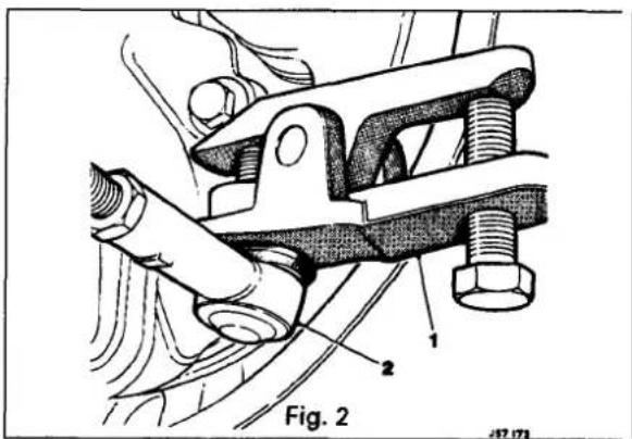
10.6 FRONT HUB ASSEMBLY, RENEW
SRO 60.25.01
10.7 FRONT HUB BEARING END FLOAT, CHECK AND ADJUST
SRO 60.25.12
10.8 FRONT HUB BEARING, RENEW
SRO 60.25.16
10.9 FRONT HUB OIL SEAL, RENEW
SRO 60.25.17
Disassemble
■ Disconnect vehicle battery ground lead.
■ Support the vehicle at the front and remove the appropriate road wheel(s)
■ Remove brake caliper and disc assemblies see SRO 70 10 10, section 12 for removal method only.
Note: Donot allow thecaliperto hang by either harness or flexible hose.
WARNING: DO NOT INHALEBRAKE PADDUST, IT MAY DAMAGE YOUR HEALTH
- Prise of thehub grease cap (1 Fig. 3). Remove and discard cotter pin (2 Fig. 3), pull off castellated nut retainer (3 Fig. 3). Remove the hub nut and bearing washer. Carefully remove the hub assembly (4 Fig. 3) from the stub axle.
- Huboil seal. Prisethe original seal from the spigot and discard.
■ Remove all traces of grease and dirt from the stub axle and back plate.
■ Lightly lubricate the stub spigot (to ease assembly of the seal) and assemble the seal to the spigot using special tool JD 179 (Fig. 4).
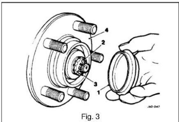
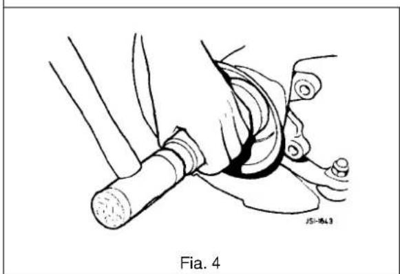


■ Pack the annular gaps of the oil seal lips with grease.
Ensure that the hub inner seal diameter is free of debris or damage and is lightly lubricated prior to assembly.
■ Bearing. Wash the hub assembly thoroughly and 'drift' the affected bearingcup(s) from the hub.
Note: Only replace complete bearings, never cup or race in isolation.
- Hub. At this point the hub may be renewed if required.
Assembly
■ Bearing. Assemble the inner bearing track to the hub using service tool 18G 134 and adaptor JD 550 - 5/1. Assemble the outer bearing cup to the hub using service tool 18G 134 and adaptor JD 550 - 5/2. Pack each race with approximately 4 ml of grease and position the inner race onto the stub axle. Apply a smear of grease to hub inner surfaces and bearing cups. Assemble the hub to the stub axle followed by outer race, bearing washer and hub nut.
Note: It is not necessary to fill the hub cavity with grease, merely protect from corrosion with a coat of lubricant. 'Seat' the bearings by slightly tightening the hub nut whilst rotating the hub. Do not apply load without rotation.
■ End float. Set a Dial Test Indicator(DTI) as shown in Fig. 1 and adjust the hub nut to achieve the correct end float. As the adjustment is made, continually load the hub axially in both directions.
■ Without disturbing the end float setting fit the castellated nut retainer so that it aligns with both hub nut and stub axle drilling.
- Secure nut retainer using a new cotter pin.
■ Assembly and fitting is the reversal of this procedure noting that; all fixings MUST be tightened to specification and operation of the braking system verified.

SECTION CON TENTS
Sub-Section Title SRO Page
I to IV ...... Preliminary Pages ...... i
11.1 Introduction 1
11.2 ...... Front Suspension. Description ...... 1
11.3 Rear Suspension, Description 2
11.4 Diagnosis & Testing 3
11.4.1 Diagnosis& Testing. Tire Wear 3
11.4.2 Diagnosis & Testing. Vibration & Roughness 3
11.4.3 Diagnosis & Testing. Front End Inspection 4
11.4.4 Diagnosis & Testing. Upper / Lower Ball Joint Inspection 4
11.4.5 Diagnosis & Testing. Damper Inspection 4
11.4.6 Diagnosis & Testing. Rear Suspension Inspection 5
11.4.7. Diagnosis & Testing. Vehicle Inspection 5
11.4.8 Diagnosis& Testing. Diagnostic Procedure Chart 6
- SERVICE TOOLS & EQUIPMENT
| Illustration | Jaguar Number | Description | Notes | |
 | JD1D | IHub Remover Rear Suspension | ||
| Not illustrated | JD 60 | ‘Nishbone Upper Bush Remover/Replacer | ||
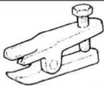 | JD100 | IRemover Steering Arm and SwivelIHub Ball Pins | ||
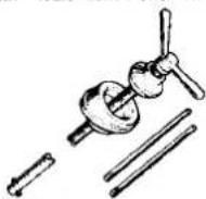 | JD115 | Spring Compressor Front Suspension | ||
 | JD133 | ‘Camber Tie Down Link (Front) | ||
 | JD135 | Remover/Renewer Front DamperLower Bush | ||
 | JD143 | IRemover/ Renewer SuspensionBushes (Main Tool) | ||
 | JD143-1 | Adaptor Ring Front Sub Frame RearBushes | ||
 | JD143-2 | Anvil adapter | ||
 | JD143-3 | Adaptor Remover / RenewerSuspension Bushes | ||
 | JD143-4 | Adaptor Remover / Renewer Suspension Bushes (Bottom Front Wishbone Inner) | ||
| Not illustrated | JD199 | Spring Compressor Rear Suspension | ||
| Not illustrated | JD199-1 | Damper Retaining Tie Rear Suspension | ||
 | JD 550-6 | Adaptor Replacer Rear Hub Pivot Bearing Cup | ||
 | 18G 134 | Driver Handle | ||
 | 18G 284 AAH | Adaptor Remover Main Shaft Pilot Bearing Outer Track | ||
 | 18G 284 | Impulse Extractor (slide Hammer) UNF. Basic Tool | ||
| Fixing | Tightening Torque (Nm) |
| To be issued |
| Description | Uses | Notes |
| LM Multi-purpose grease | Lower damper boltWishbone to crossmember fulcrum shaft | |
| Molib Alloy P1907 No1 | Stabilizer mounting bushes& rear damper top guide bush | |
| Molykote 11 1 | Caliper to carrier bolts/guide pins |
| Application | Specification |
| Camber angle front suspension | +0.3° to - 0.8' |
| Caster angle (Same setting each side of vehicle) | 3.09° 6.0° |
| Wheel alignment | 5' Toe-in ± 10' |
Note: Geometry isto bechecked/set using the mid-laden setting-links. Setting height should correspond to the following dimensions:
Front 153 ± 5mm under front crossbeam (AJ16)
Front 143 ± 5mm under front crossbeam (V12)
Rear 160 ± 5mm under rear edge of'A' frame
11.1 INTRODUCTION
This section describes the front and rear suspension systems, and also covers diagnostic procedures.

11.2 FRONT SUSPENSION, DESCRIPTION
The upper rear wishbone (1 Fig. 1) and the upper front wishbone (2 Fig. 1) are pivoted on the upperfulcrum bolt (3 Fig. 1), passing through the front cross beam assembly. They are also fitted via an upper ball joint assembly (4 Fig. 1) to a vertical link accommodating the stub axle (5 Fig. 1), whereas the vertical link is fitted via a lower ball joint assembly (6 Fig. 1) to the lower wishbone assembly.
The lower wishbone assembly comprises a lower rear wishbone(7 Fig.1), lower front wishbone (8 Fig.1), damper (9 Fig.1) (incorporating damper bush 10 Fig.1) and spring pan (1 1Fig.1) supporting the roadspring (12 Fig.1). The lower wishbone assembly is pivoted on the bushed lower fulcrum shaft (13 Fig.1) which also passe through the cross beam assembly.
Both independent front suspension assemblies are linked by a stabilizer bar (14 Fig.1) which is secured to the cross member using a fixing arrangement of mounting rubbers (15 Fig.1, clamps (16 Fig.1), nuts bolts, washers (17 Fig.1) and two link arm assemblies (18Fig.1). Each link arm assembly is fitted to one end of the stabilizer bar and to one end of the lower front wishbone using a fixing arrangement of bolts washers and self locking nuts.
All suspension loads, except the damper, are fed into a pressed steel crossbeam which is isolated from the body by rubber bushes. This mounting method allows the necessary amount of compliance.
The degree of caster is adjustable via shims positioned on either side of the upper ball joint assembly but camber is factory set and is not adjustable. The vertical link and the steering arm form a single forging. Cast iron hubs rotate on twin tapered roller bearings.


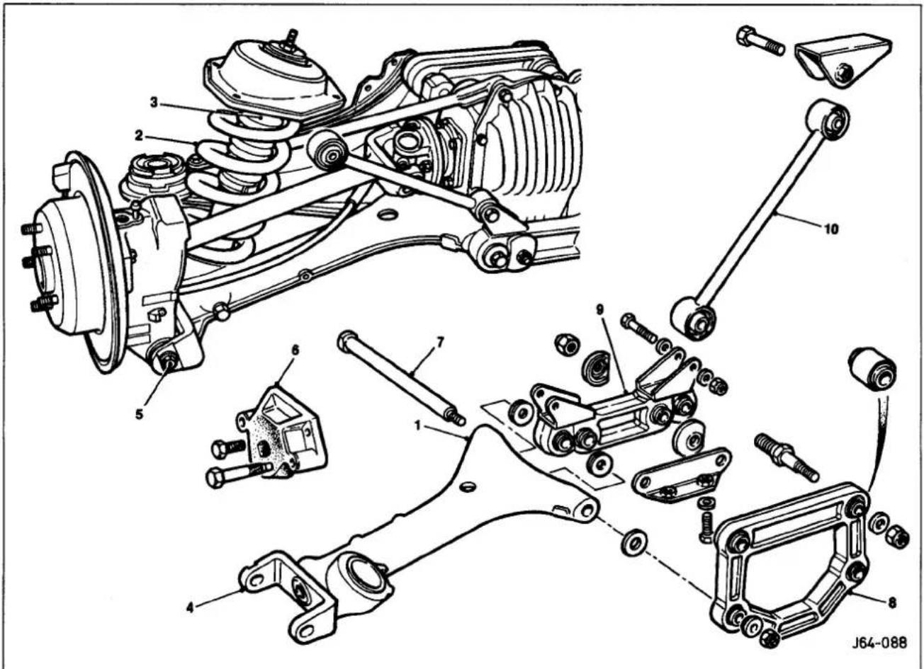
Fig. 1 Rear Suspension layout
11.3 REAR SUSPENSION, DESCRIPTION
The vehicle's rear suspension layout features a cast wishbone complete with integral lower spring pan (1 Fig.1) supporting the independently mounted damper(2 Fig.1) and road spring (3Fig.1).
The lower wish bone arm is bolted to the hub carrier (4 Fig. 1) by means of a pivot bolt (5 Fig. 1), allowing for toe-in adjustment. When the pivot bolt is seated correctly in the plate located on the wishbone arm, it has a small clearance at the sides but full clearance at the top and bottom.
Rotation of the bolt head, with eccentric constrained between the vertical faces, causes the bolt shank to be moved in the horizontal plane, thus displacing the hub carrier and effecting wheel alignment adjustment.
The snubber (6Fig.1) positioned above the hub carrier, prevents this from touching the vehicle body.
The hubcarrier/wishbone assembly, is pivoted on the wishbone fulcrum bolt (7 Fig.1) and is then secured by a nut and washerfixing arrangement to the pendulum assembly (Fig.1) and the wishbonetie assembly (Fig.1). The differential strut (10 Fig.1) is fastened to the wishbone tie assembly and to a bracket, welded to the vehicle body. Both, the pendulum and the wishbonetie assembly are fitted to the differential unit which is mounted on to a mounting frame and a rear frame carrier.
The supercharged vehicle (manualonly), the XJ12 and the sport versions are equipped with a rear stabilizer bar, a differential monostrut instead of two single struts, a modified wishbone tie and two stabilizer bar drop links which are seated on the lower wishbone cast bosses.

11.4 DIAGNOSIS AND TESTING
11.4.1 Tire Wear
Tires should be inspected as abnormal or excessive wear may be caused by incorrect wheel alignment, wheel/tire imbalance, or incorrect tire pressure.
11.42 vibration and Roughness
Vibration, roughness, and shimmy conditions may be caused by excessive tire or wheel runout, worn or cupped tires, or wheel and tire unbalance.
Most of these conditions are due to irregularities in the road surface, hence driving the vehicle on different types of road surface will often indicate the cause of the condition.
Do not automatically suspect the tires when attempting to diagnose a vibration concern as other sources of vibration may include:
- Loose or worn wheel bearings.
- Loose or worn suspensions or steering components.
- Worn or damaged drive shaft slip yoke joint.
- Front disc rotor runout.
○ Loose engine or transmission supports. - Engine driven accessories.
- Driveline alignment.

Before investigating any other vibration concerns, a road &est and customer interview (if possible) should be carried out. This can provide much of the information needed to find the source of vibration.
Drivethe vehicle on a road that is preferably smooth and free of undulation and if vibration is apparent note, the speed at which the vibration occurs, what type of vibration occurs in each speed range (mechanical or audible), how the vibration is affected by changes in vehicle speed, engine speed and engine torque, and the type of vibration sensitivity (torque sensitive, vehicle speed sensitive, or speed sensitive).
Some of the condition terms used when describing sources of vibration are explained as follows:
- Torque Sensitive
This condition can be improved or worsened by accelerating, decelerating, coasting, maintaining a steady vehicle speed and application of engine torque. - Vehicle Speed Sensitive
This means that the vibration always occurs at the same vehicle speed and is not affected by engine torque, engine rpm, or transmission gear selection.
- Engine Speed Sensitive
This means that the vibration occurs at varying vehicle speeds when a different transmission gear is selected. It can sometimes be isolated by increasing or decreasing engine speed with the transmission in 'NEUTRAL', or by stall testing with the engine in gear. If the condition is engine-sensitive, the condition is not related to tires.
If the road tests indicates that the vibration is related to the tires or wheels, use a 'Tire Wear Diagnosis Chart' to investigate the cause of concern. Should the road test indicate that there is tire whine, but no shake or vibration, the noise originates from the contact between the tire and the road surface.

11.4.3 Front End Inspection
Donot check and adjust front wheel alignment without carrying out the following inspection for front end damage and wear:
■ Check for specified air pressure in all four tires.
- Raise front of vehicle off the floor; grasping upper and lower surface of the tire, shake each front wheel to check for worn bearings.
- Check front suspension lower arm ball joint and mounts for looseness, wear and damage.
- Check brake caliper mountings.
- Check steering gear mountings and all steering linkages for looseness.
■ Renew parts if necessary.
- Grasp upper and lower surface of tire and shake each wheel to check wheel bearing end play.
- Check the action of the front dampers and the condition of their attachments, as sticking or binding front dampers may not allow the vehicle to settle into a normal level position, possibly affecting the frontwheel alignment.
Note: Front wheel bearings are adjustable(0.001 to 0.003 in. endfloat).
11.4.4 Upper / Lower Ball Joint Inspection
■ Check the wheel bearings.
- Inspect the front suspension upper joint and renew front suspension lower wishbone if needed.
- Raise vehicle and position floor jacks beneath the front suspension lower wishbone.
- Grasp the lower edge of the tire and move the wheel in and out.
■ While moving the wheel, observethe upper and lower wishbone.
■ Movement between the vertical links and the wishbones indicates abnormal ball joint wear.
■ Renew ball joints.
■ Check the front wheel bearings.
■ Check for excessive play and wear.
11.4.5 Damper Inspection
Note: The gas-pressurized hydraulic front dampers are not serviceable, adjustable or refillable.
- Verify that all attachments of the suspension components and the front dampers are tight. Renew any front damper that has a damaged integral lower mounting bushing.
■Check front dampers for external damage.
■Check for oil leakage and vehicle sag.
Oil Leak
Leakage is the condition in which the entire damper body is covered with oil and from where it will drip on to the pavement. Due to correct damper lubrication a light film of oil (weepage) can usually be seen on the upper portion of the damper.
Should there be any leakage, ensure that the fluid does not originate from sources other than the front damper. Renew worn or damaged dampers.
Vehicle Sag
Renewingfront dampers will not correct the problem of vehicle sag, as basically this is controlled by the spring units.
11.4.6 Rear Suspension Inspection
- Check for evidence of fluid leaks on rear dampers.
■ Check damper operation. - Check condition of rear wishbone bushings and rear suspension strut bushings.
■ Renew damaged or worn components.
11.4.7 Vehicle Inspection
- Check all tires for correct inflation pressure.
- Checktirecondition to confirm correct front end alignment, tire balance and overall tire conditions such as separation or bulges.
- Check the vehicle attitude for evidence of possible overload or sagging.
- Check luggage compartment area.
■Road test vehicle to confirm customer's concern.
11.4.8 Diagnostic Procedure
| Condition | Possible Cause | Action |
| Wander/Pull/Drift | Side-to-side difference in caster.Tire pressureSteering gear or linkage worn or defective.Tire conicity | Check the alignment and if incorrect, adjust the caster if needed. Inspect components for wear or damage.Check for abnormal loading.Check steering systemInspect tire for excessive wear.Check and adjust the tire air pressure.Note: Excessively worn or uneven tires can cause pull/drift. |
| Hard steering | Power steering gear or linkage worn, damaged, or incorrect adjusted.Wear of front suspension lower/upper wishbone ball joints. | Check steering system.Renew ball joints. |
| Brake pull | Unequal tire pressure.Brake system fault(s) | Inflate the tires to correct and uniform pressure.Check the brakes. |
| Shimmy | Wheel/tire imbalance or runout.Damaged tires, unbalanced or damaged wheels.Incorrect wheel alignment.Steering system malfunctionFront damper malfunction.Loose front damper mounting.Damaged front suspension upper or lower ball joints.Damaged or worn sub-frame to body mounting.Damaged or worn stabilizer bar insulators.Damaged or worn stabilizer bar link.Damaed or worn wheel bearina. | Check wheels and tires.Check the tires and renew if necessary.Balance the wheels if necessary.Adjust wheel alignment.Check steering system.Renew front damper if necessary.Tighten front damper mounting.Renew upper and lower ball joint.Renew rear suspension bushing.Renew insulators.Renew link.Renew/adjust wheel bearing. |
| Dog-Tracking | Rear suspension damage. | If the caster is uniform, check and compare the wheelbase at the right and left sides. If different, inspect the suspension components for wear and damage. |
| Bump steer (unequal side-to-side) | Worn steering gear mounting bracket housing insulators. | Renew bracket housing insulators. |
| Sawteeth pattern or excessive tire wear | Excessive toe-in (high edges inboard) or toe-out (high edges outboard). | Check and adjust toe-in. |
| Uneven tire wear (outer or inner shoulder) | Incorrect tire pressure.Excessive toe.Excessive positive or negative camber. | Correct tire pressure.Check toe and adjust if needed.Check the camber and if incorrect inspect the related components for wear or damage. |
| Front/rear suspension noises | Loose/missing front dampers and front damper bolt to front suspension lower wish bone. | Tighten/renew damper bolts.Inspect wheel hubs. |
| 3ody 'rolls' | Weak front stabilizer bar.Damaged or worn lower wishbone stabilizer bar insulator.Damaged or worn stabilizer bar linkDamaged or worn rear suspension wishbone bushing.Damper malfunction.Worn or deteriorated rear stabilizer bar bushing(s). (supercharged, sports andXJ12 only) | Renew front stabilizer bar.Renew insulators.Renew link.Renew bushing.Renew damper if necessary.Renew Bushina |
| 3ody leans | Damaged or worn rear wishbone bushing and weak springs.Worn or deteriorated rear stabilizer bar bushing(s). (supercharged, sports andXJ12 only) | Renew bushings and springs.Renew Bushings. |
| Poor ride comfort | Front or rear damper malfunction.Weak spring(s) | Renew dampers.Renew springs. |
| General driving nstability | Damaged tires or unbalanced wheels.Incorrect wheel alignment.Steering system malfunction.Damagedfront suspension lower and upper ball joints.Damaged or worn sub-frame to body mounting.Damaged or worn stabilizer bar linkDamaged or worn lower wishbone stabilizer bar insulator.Weak spring(s)Worn or deteriorated rear stabilizer bushing (s).(supercharged, sports andXJ12 only) | Check the tires.Adjust the wheel alignment.Check steering system.Renew ball joints.Renew bushing.Renew link.Renew insulator.Renew springs.Renew bushing |
| Steering wheel does not return properly | Damaged tires or unbalanced wheels and incorrect tire pressure.Incorrect wheel alignment.Steering system malfunction.Damagedfront suspension lower and upper ball joints. | Check tires.Adjust the wheel alignment.Check steering system.Renew ball joints. |
| Steering wheel pulls:one side | Incorrect tire pressure.Damagedfront suspension lower and upper ball joints.Braking system malfunction.Steering system malfunction.Damaged or worn sub-frame to body mounting.Damaged tires, unbalanced wheels and incorrect tire pressure. | Check and correct tire pressure.Renew ball joints.Check brakes.Check steering system.Renew bushing.Check tires. |
| Abnormal noise from suspension system | Poor lubrication/wear of wheel bearing.Wear of front suspension lower and upper ball joints.Damaged or worn front stabilizer barDamaged or worn stabilizer bar link.Damaged or worn stabilizer bar bracket.Looseness of suspension connections.Damaged or worn rear wishbone bushing.Front and rear damper malfunction.Weak spring.Worn or deteriorated rear stabilizer bushing (s).(supercharged, sports and XJ12 only) | Renew wheel bearing.Renew ball joints.Renew stabilizer bar.Renew link.Renew bracket.Tighten connections.Renew bushing.Renew dampers.Renew bushing |


SECTION CONTENTS
Sub-Section Title SRO Page
i to iv ...... Preliminary Pages ...... i
12.1 Anti-Lock Braking System (ABS) General Description 12.1
12.1.2. Anti-lock Braking/ TractionControl Operation 12.3
12.1.3 Anti-lock Braking Operation 12.4
12.1.4 Actuation Components 12.5
12.1.5 ABS Components 12.6
12.1.6 Calipers 12.7
12.1.7 Parking Brake 12.9
12.1.8 Wheel Speed Sensors 12.11
12.1.9 Hydraulic Operation - ABSCM 12.12
12.1.10 Hydraulic Operation - ABS/TC CM 12.14
12.2 Fault Diagnosis and Testing 12.16
12.3 Brake Fluid Level Check 12.18
12.4 Brake System Bleeding 12.19
12.4.1 System Bleeding - General Instructions 12.19
12.4.2. System Bleeding After Brake Fluid Renewal 12.19
12.4.3 System Bleeding After Tandem Master Cylinder Renewal 12.19
12.4.4. System Bleeding After Hydraulic Control Module Renewal 12.20
12.4.5. Bleeding After Renewal of Caliper 12.20
12.5 ...... General Fitting Instructions ...... 12.2
12.5.1 General Fitting Instructions, Brake Fluid 12.2.1
12.5.2. ...... General Fitting Instructions, Hoses ...... 12.2.1
12.5.3 General Fitting Instructions, Pipes 12.2
12.6 Rear Wheel Speed Sensor - Renew 70.60.04 12.22
12.7 Hydraulic Control Module - Renew 70.60.18/19 12.23
12.8 Pressure Conscious Reducing Valves 70.60.21 12.25
12.9 ABS/TC CM-Renew 70.60.02/20 12.26


- SERVICE TOOLS & EQUIPMENT
| Illustration | Jaguar Number | Description | Notes | |
 | JD.142 | Parking brake cable remover | ||
 | 186.672 | Replacer disc brake piston seal | ||
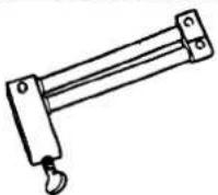 | 6947017 | Brake hose clamp, Girling | ||
| not illustrated | JDS.9013 | Brake pedal hold down tool | ||
II. TORQUE TIGHTENING SPECIFICATIONS
| Fixing | Tightening Torque (Nm) |
| Vacuum booster to pedal box | 21-29 |
| Tandem master cylinderto booster | 21-29 |
| Hydraulic module to module bracket | 18-26 |
| Caliper guide pins | 25-35 |
| Caliper to vertical link | 120-160 |
| Caliper to hub carrier | 54-66 |
| Pipe connectors to hydraulic module: M12 | 15-19 |
| M10 | 12-16 |
- SERVICE MATERIALS
| Description | Uses | Notes |
| Molykote 111 | Caliper to carrier securing bolts |
IV. SERVICE DATA
| Front brakedisc run out | 0.101 mm (0.004 in) max. |
| Front brakedisc parallelism | 0.0127mm (0.0005in)max. |
| Rear brake disc run out | 0.101 mm (0.004 in) max. |
| Rear brake disc parallelism | 0.0127mm (0.0005in)max. |
12.1 ANTI-LOCK BRAKING SYSTEM (ABS), GENERAL DESCRIPTION
The anti-lock braking system (ABS) components are combined with a hydraulic booster and tandem master cylinder (TMC) to provide a two-circuit braking system. The anti-lock braking system comprises the following components:
- Four inductive wheel speed sensors, hub end mounted
- ABS warning light
Hydraulic module.
The hydraulic module consists of an electric motor driven pump, two low pressure accumulators, valve block and an ABS electronic control module.
Note: Electronic control modules for vehicles without traction control are designated ABS CM. Control modules for vehicles with traction control are designated ABS /TC CM.
The valve block houses solenoid operated valves which are activated by voltage signals from the control module. The signals are generated using wheel speed information received from the wheel speed sensors.
For vehicles without traction control the valves operate on three circuits, two front and one rear, as necessary to prevent wheel locking during braking. Brake pressure is modulated individually at the front wheels and collectively at the rear. Rear wheel control operates on a 'select low' principle i.e. locking in either wheel is sensed, and controlled brake pressure is applied to both wheels.
For vehicles with traction control the valves operate on four circuits. During ABS control the rear wheel are controlled on a 'select low' principle (as above), but during traction control operation the rear wheels are controlled individually.
Note: Functional and diagnostic information for the ABS CM and the ABS / TCCM is contained in the Electrical Diagnostic Manual(EDM), Section 12.
ABS Warning lamp / Traction Control Warning lamp/Fluid level Indicator
The ABS and traction control warning lamps, mounted in the instrument panel, indicate a fault in the ABS or traction control. These systems are inhibited or disabled when the lamps are lit, although conventional braking is unaffected.
When the ignition is switched on, an ABS self test is initiated. During this test, the ABS and traction control warning lamps are lit for approximately 1.7 seconds and then extinguish. A fault is indicated if the warning lamps remain lit or come on whilst the vehicle is being driven.
Note: The ABS self test is masked by the 5 second lamp test initiated when the ignition is switched on.
The fluid level indicator lamp, mounted in the instrument panel, is lit when the brake fluid falls below the minimum mark on the brake fluid reservoir.
ABS / Traction Control- Inhibit / Disable
Faults conditions are detected by the ABS/TCCM which disable the ABS and traction control until the fault is rectified. The ABS and traction control warning lights on the instrument pack remains lit whilst a fault exists. The system will be disabled when the following conditions occur:
Valve failure
- Sensor failure
o Main driver failure (internal ABS/TC CM fault)
o Redundancy error (internal ABS / TC CM fault)
- Overvoltage/ undervoltage
o Pump motor failure.
○ Throttle valve actuator motor failure (traction control vehicles only).
○ Throttle valve actuator potentiometer failure (traction control warning light only).
The input frequency from each wheel speed sensor signal is translated by the ABS/TC CM, into a comparable wheel speed. The ABS/TC CM continually monitors the system. False wheel speed information, such as sudden speed changes in excess of 20 km/h or excessive speeds, are detected as a 'sensor malfunction'. The ABS/TC CM reacts to fault conditions in the following ways:
Inhibit - ABS / traction control is inhibited until the sensed speed return to within an acceptable limit, whereupon ABS / traction control is restored. Conventional braking is unaffected. Depending on vehicle speed the ABS / traction control warning lights may come on.
Disable - ABS /traction control is Disabled (switchedoff) and the ABS /traction control warning lights come on. The system will not be restored until the engine is switched off and restarted or the fault has been rectified. After the system has been disabled, the warning lamps remain on until the vehicle has reached a speed of 20 km/h during the first ignition cycle after fault rectification.
Full diagnostic information for the ABS/TC CM is given in the Electrical Diagnostic Manual(EDM), Section 12.
12.1.2. Anti-lock Braking / Traction Control Operation

The vacuum booster (see Fig. 1) is mounted on the brake pedal box and secured by three bolts. Brake pedal force is increased by the vacuum booster which activates the Tandem Master Cylinder(TMC) intermediate piston. Brake fluid is supplied to the pump inlet ports on two separate circuits. The primary circuit supplies the front brakes whilst the secondary circuit supplies the rear brakes.
The rear wheels are controlled collectively on a 'select-low' principle during ABS operation. During traction control, separate circuits allow individual control of the rear wheels. To facilitate this the valve block has four outlet ports.
The ABS / TCCM is integrated with the valve block. The pump, motor, valve block and control module are supplied as a unit and are non-sewiceable. Faulty units must be renewed as a whole.
Both front and rear brakes on all vehicles are fitted with single piston caliper assemblies. Ventilated brake rotors, with provision for parking brake shoes at the rear, are fitted all round.
Pressure conscious reduction valves (PCRVs) are fitted between the outlet of the valve block and the rear brake circuit to optimize. The valves are fitted to prevent over braking due to the increased size of the rear brake calipers which are required for traction control. Upto a threshold of 15 bar, brake pressure to the front and rear brakes is equal. Above 15 bar the PCRVs reduce pressure to the rear brakes to provide a closer balance between front and rear brakes and optimize road adhesion.
Wheel speed sensors are fitted to all wheels to transmit wheel speed information to the control module. The module uses this information to modulate brake pressure during anti-lock braking or traction control.
- Anti-lock Braking Operation

The rear brakes (see Fig. 1) are controlled collectively on a 'select-low' principle. Under ABS braking conditions, equal brake pressure is applied to both rear calipers, although only one wheel may have a tendency to lock.
The valve block has three outlet ports, Brake fluid volume is supplied equally to the rear brakes via the 3-way brake pipe connector.

12.1.4. Actuation Components
The vacuum booster (1 Fig.1) is mounted on the brake pedal box and secured by three bolts. The TMC locates on two studs on the vacuum booster. Two lugs locate the fluid reservoir on the TMC and is secured by a split pin.
The vacuum is drawn from the inlet manifold. At the vacuum booster, the vacuum hose is connected to the vacuum chamber via an elbow connector. At the inlet manifold the vacuum hose connector is of the push-on quick-release type.
Applied pedal force is increased by the vacuum booster which actuates the intermediate piston of the TMC (2 Fig. 1). The boost ratio supplied by the vacuum booster is 6.5 : 1.
Note: The vacuum booster and the TMC are supplied as a unit but are individually serviceable.
The brake fluid reservoir (3 Fig. 1) is fitted with a fluid level indicator switch which opens when fluid level is low and lights the fluid level indicator Light.


12.1.5. ABS Components
Hydraulic Module
The hydraulic module is located under the bonnet adjacent to the engine compartment firewall. It is secured within a steel mounting bracket at three securing points. All electronic and power connections are made through one cable loom connection.
The hydraulic pump(1 Fig. 1) is a reciprocatingtwo-circuit pump in which one brake circuit is assigned to each pump circuit. The pump supplies adequate pressure and volume supply to the brake circuits under anti-lock braking conditions. The pump is driven by and electric motor (2 Fig. 1). The pump housing incorporates two low pressure accumulators and damping chambers for each brake circuit.
A modulator valve block (3Fig. 1) incorporates the ABS CM or ABS/TC CM (4 Fig. 1). Vehicles with traction control are fitted with a throttle position actuator (5 Fig. 1), which is an electrical device controlled by the ABS/TC CM.
Valve blocks on vehicles without traction control comprise six solenoid valves, three normally open (NO) inlet valves and three normally closed (NC) outlet valves. These valve blocks have three outlet ports. Valve blocks on vehicles with traction control comprise nine solenoid valves, four NO inlet valves, four NC outlet valves and one special isolating valve. Fig. 2 shows a hydraulic module for vehicles with traction control. The valve block(2 Fig. 2) has four outlet ports (Individual control of the driven wheels).
ABS CM, ABS/TC CM
The ABS CM or ABSTC / CM locates beneath the modulator valve block and is secured by two screws. The CM houses the solenoids which operate the inlet and outlet valves of the modulator valve block. When fitted, the valve stems locate in the CM mounted solenoids. There is no electrical connection between the CM and the modulator valve block. Fig. 3 shows an ABS TC / CM having nine solenoids.
The CM functions include the following:
- Providing control signals for the operation of ABS and traction control solenoid valves
○ Calculating wheel speed from voltage signals transmitted by the wheel speed sensors
○ Monitoring of all electrical components - On Board Diagnostics(OBD): storage of possible failures in a non-volatile memory.
The signals from the four wheel speed sensors are independently processed by the ABS CM or ABS/TC CM, calculating numerical values which correspond directly to the wheel speed. These values are converted into control signals for pressure modulation during ABS control.
The ABS and traction control are continuously monitored, whilst the ignition is on, for possible faults and interruptions. If a fault is detected, the module deactivates the ABS and indicates this by lighting the ABS warning lamp. In a fault condition, conventional braking is unaffected. The module stores fault codes in a non-volatile memory which can be read via the OBD link.
Note: For electrical diagnostic information on the ABS / traction control systems, refer to EDM, Section 12.

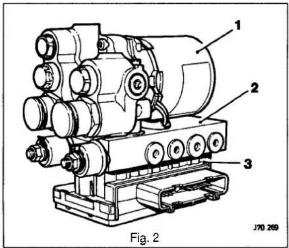
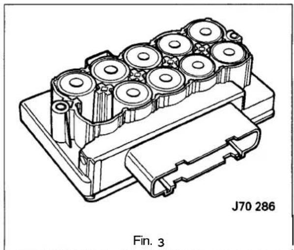
12

12.1.6 Calipers
Both front and rear brakes on all vehicles are fitted with single piston caliper assemblies that act upon 28mm thick ventilated brake rotors (front brakes) and 20mm thick ventilated brake rotors/hubs (rear brakes). Rear ventilated brake rotors/hubs are fitted to cope with the increased demands brought about by traction control.
The brake rotors must be renewed when the minimum thickness specified below is reached:
- Front brake rotor- 27mm
- Rear brake rotor- 18.5mm.
On the front brakes (Fig. 1) two bolts secure the caliper carrier to the suspension vertical link.

On the rear brakes (Fig. 2) two bolts (wire locked) secure the caliper carrier to the hub carrier.
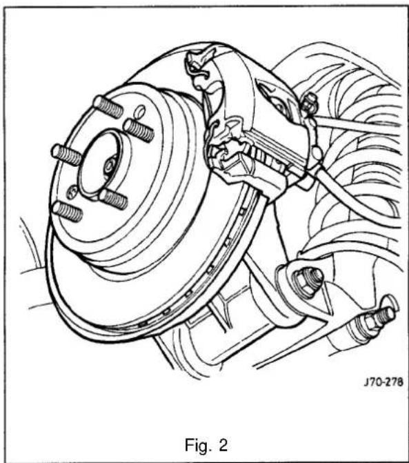
The caliper (1 Fig. 1) is mounted on the carrier (2 Fig. 1) by means of two guiding pins (3 Fig. 1) and a caliper retaining clip (5 Fig. 1). The guiding pins (3 Fig. 1) slide in bushes (4 Fig. 1) fitted to the caliper.
The guiding pins are fitted with dust caps which must be fitted when reassembling the caliper.
Inspection and Cleaning
WARNING: BRAKE LINING DUST CAN, IF INHALED, DAMAGE YOUR HEALTH. ALWAYS USE A VACUUM BRUSHTO REMOVE DRY BRAKELINING DUST. NEVER USE AN AIR LINE.
When fitting new brake pads always take necessary precautions and remove the brake dust from around the caliper area. After renewal, pump the brake pedal several times to centralize the new brake pads.
Note: If both front and rear calipers have been removed from the vehicle, take care not to mix up left and right hand caliper bodies.

Remove all brake dust from the caliper, carrier and brake rotor. Thoroughly clean the pad abutment areas, avoid damaging the piston and dust cover.
CAUTION: When cleaning brake components only use a proprietary fluid. Never use petrol. Use of petrol, paraffin or other mineral based fluids can prove dangerous.
Examine all the components for signs of wear, damage and corrosion. Pay particular attention to the piston and piston bore.
Remove caliper body corrosion with a wire brush or wire wool. No attempt should be made to clean a badly corroded or scored piston bore. The caliper must be renewed
CAUTION: No attempt should be made to clean corroded bolts.
Inspect the caliper guide pins, ensure that they are not corroded or seized and that the caliper moves freely. If they are difficult to remove or corroded in any way, they must be replaced together with new dust covers.
CAUTION: Ensure that working surfaces and hands are clean. Use only brake fluid of the correct specification to lubricate the new seals when fitting.
When reassembling always renew piston seals. Lubricate the new piston seal and fit carefully to the inner groove of the piston bore.
12.1.7. Parking Brake
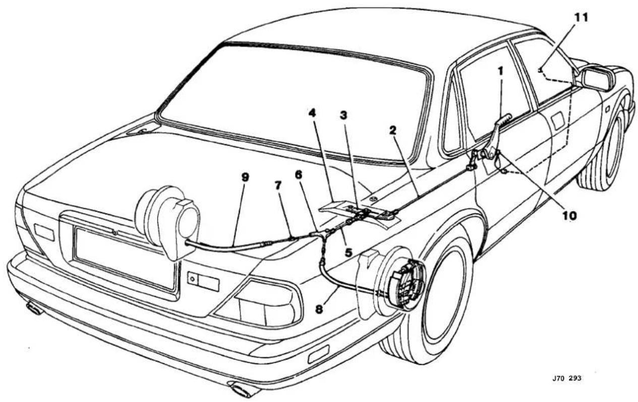
- Parking brake lever
- Front cable
- Relay lever
- Driveshaft securing bracket
- Intermediate cable
-
Cable equalizer
-
In-line cable connector
- Rear cable RH
- Rear cable LH
- Parking brake switch and harness
- Parking brake warning lamp
Fig. 1 Parking Brake Layout
All vehicles are fitted with identical parking brake systems.
When the parking brake levels operated, the cable system applies equal force to both RH and LH brakeshoe expander assemblies. The brake shoes expand and press against the hub assembly, locking the rear wheels.
The handbrake lever, ratchet assembly and warning light switch (item1) are mounted on the transmission tunnel by means of threeflanged screws a blanking plate and gasket. The front cable (item 2) is connected to the relay lever (item 3) which is mounted on the driveshaft securing bracket (item 4). The relay lever operates the intermediate cable (item 5) which incorporates an adjusting screw to allow cable tension to be adjusted. The intermediate cable operates the equalizer which ensures that equal force is applied to RH and LH parking brakes via rear cable RH (item8) and rear cable LH (item9). The rear cables are adjustable to allow cable tension to be adjusted.
The park brake switch (item 10) latches when the lever is operated and lights the parking brake warning light (item 11 mounted in the instrument panel.
Parking Brake Adjustment
Cable slack must be removed by adjustment of the intermediate cable length. The handbrakeshould be fully on between three and five clicks.
Parking Brake Shoe Assembly
The parking brakes are of the duœsewo type. The expander assembly (6 Fig. 1) is mounted on the backplate mounting lug. The brake shoes locate on the expander assembly and the adjuster(1 Fig. 1). These are held in position by the upper and lower return springs(4 and 5 Fig. 1) and the hold down springs(2 Fig. 1). The adjuster allows manual adjustment of the brake shoes.
To remove the brake shoe assemblies the handbrake must be released and the adjuster slackened.
The use of a spring removal tool is recommended when removing the brake shoes. Strong pliers may be used, but there is a risk of both personal injury and loss of components, should the pliers slip.

Inspection and Cleaning
Clean and examine all components for wear or damage, renewing parts as necessary.
When reassembling the expander assembly, liberally grease the components using a proprietary mechanical brake grease. Lightly grease the threads of the adjuster.
CAUTION: Donot get grease onto the lining material. Light surface contamination cable removed with emery cloth, but heavy penetration of grease or fluid will render the material unsuitable for further use and the linings must be renewed.
Re-assembly
When reassembling the brake shoes, lightly grease the shoe tips and back plate contact area. The brake shoes and the expander assembly should be fitted to the backplate with the lower return spring in position. When the brake shoes are located, the adjuster, upper return spring and hold down springs should then be fitted. The brake shoes should be adjusted so that the brakerotor/hub can just be fitted. Final adjustment should allow the brakerotor/hub to rotate without excessive drag. Light running contact is permissible.
12.1.8. Wheel Speed Sensors
A toothed wheel, which turns with the road wheel, induces an ac voltage signal in the wheel speed sensor. The frequency and amplitude of the ac voltage varies directly in relation to wheel speed, providing the control module with wheel speed information. Wheel speed sensors are fitted to each road wheel.
Front
The front sensors are mounted on the vertical link (1 Fig. 1).
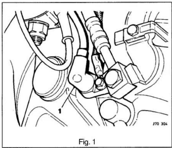
Rear
The rear wheel sensors are mounted on the hub carrier (Fig. 2).

12.1.9 Hydraulic Operation-ABS CM
The TMC primary circuit (item 1) applies brake pressure to the front brakes. Individual control of the front wheels is provided by solenoid valves, Valves (items15 and 18) control the front left brake circuit (item21). Valves (items16 and 19) control the front right brake circuit (item22). The TMC secondary circuit (item 2) applies brake pressure to the rear brake circuit (item 20) via valves (items 14 and 17), on a 'select low' principle.
![graph TD A["10 M"] --> B["11"] B --> C["12"] C --> D["14"] D --> E["15"] E --> F["16"] F --> G["17"] G --> H["20"] H --> I["21"] I --> J["22"] K["7"] --> L["6"] L --> M["3"] M --> N["4"] N --> O["1"] O --> P["2"] P --> Q["5"] Q --> R["8"] S["19"] --> T["16"] T --> U["15"] U --> V["14"] V --> W["12"]…](/content/2026/06/1254020/images/ba3d9a0bb86cb20956d61064711abe4d64a5762aaf06f49a1aee6b3853b988bb.jpg)
-
TMC 1 (primary circuit)
-
TMC 2 (secondary circuit
-
Tandem master cylinder
-
Vacuum booster
-
Central valve
-
Fluid reservoir
-
Fluid level indicator
-
Pump motor unit
-
Low pressure accumulator
-
Electric pump motor
-
Two circuit hydraulic pump
-
Damping chamber
-
Valve block
-
Inlet valve NO
-
Inlet valve NO
-
Inlet valve NO
-
Outlet valve NC
-
Outlet valve NC
-
Outlet valve NC
-
Rear brake circuit
-
Front brake circuit (left)
-
Front brake circuit (right)
Fig. 1

Should the ABS be initiated by a locking tendency of any wheel during braking, the pump unit (item8) is started and the appropriate NO inlet valve (item 14, 15 or 16) closes in response to signals from the control module. This action prevents further increase of brake pressure by blocking the supply of brake fluid from the TMC (item3). If excessive deceleration continues, the appropriate NC outlet valves (item 17, 18 or 19) opens, releasing brake pressure to the low pressure accumulators (item9) until the wheel accelerates again.

From the low pressure accumulators, volume is pumped back into the TMC, forcing the brake pedal back. To optimize the friction coefficient between tire and road, brake pressure is increased in small steps by closing the outlet valve and opening the inlet valve and recharging brake pressure.
During the pressure buildup phase, the volume required for replenishment is supplied by the TMC and additionally by the pump from the low pressure accumulators. Since the delivered flow is generally greater than volume flow drained from the brake circuits, the low pressure accumulators serve as intermediate accumulators to compensate for temporary volume flow peaks.
The TMC piston positions, and therefore the brake pedal, vary with the fluid displacement in the brake caliper. As controlled pressure in the brake caliper decreases and increases during ABS, the brake pedal 'cycles', informing the driver that controlled braking is in progress.
Actuation of the brake pedal, causes the central valve (item 5) in the TMC to close. This action prevents damage to the TMC piston seals.
At the end of a brake application, volume is restored to the TMC, at low pressure from the fluid reservoir (item 6).


12.1.10 Hydraulic Operation-ABS/TCCM
ABS / TCCM hydraulic modules incorporate inlet valves (items 16 and 17) and outlet valves (items 20 and 21) for each driven wheel. This enables individual pressure modulation to the rear brakes under wheel spin conditions, i.e. traction control.
Increased wheel spin of a driven wheel under acceleration causes the NO isolation valve (item 14) to be closed and the pump (item 10) to be switched on. This in response to signals from the control module.
Closing of the isolation valve blocks delivery of the pump to the secondary circuit (item2) of the TMC. The pump now draws fluid from the reservoir via the open hydraulically operated inlet valve (item13). Increased pressures now available at the inlet valves (items16 and 17) for actuating the rear brakes, thus decreasing the tendency of wheel spin.
Note: The hydraulic inlet valve (item13) switches when traction control is initiated to change the suction connection of the pump from the accumulators (item 9) to the fluid reservoir (item6) via the TMC.
![graph TD A["1. TMC 1 (primary circuit)"] --> B["2. TMC 2 (secondary circuit)"] B --> C["3. Tandem master cylinder"] C --> D["4. Vacuum booster"] D --> E["5. Central valve"] E --> F["6. Fluid reservoir"] F --> G["7. Fluid level indicator"] G --> H["8. Motor pump unit"] H --> I["9. Low pressure accumu…](/content/2026/06/1254020/images/552dd52b502447d753d0379ec11a14145ef520a552e55cbbe50a68051510c9df.jpg)

The pressure at the inlet valves corresponds to the opening pressure of the relief valve (item 15) incorporated in the isolation valve. Excess brake fluid is drained to the suction side of the pump via the relief valve and returns either to the TMC secondary circuit and on to the fluid reservoir, or is directly drawn on by the pump.
As soon as the spinning wheel has been braked down into the normal range of wheel spin, the NO valves (items 16 or 17) close to prevent any further increase in brake pressure. Depending upon the acceleration of the wheel, the NC valve (item 20 or 21) may open to decrease these secondary circuit brake pressure. NC valves (item 17 or 18) may remain closed in order to achieve a brake pressure holding phase. If the pressure in the secondary circuit needs to be increased again, the NC valve closes again (if open) and the NO valve opens, diverting the necessary volume flow. This control action, keeps the wheel in the range of optimum slip until the spinning tendency ceases.
The NO isolation valve(14) remains closed throughout the traction control cycle.
An actuation of the brake, sensed by the control module, causes the traction control mode to be terminated and the isolation valve (item 14) to be opened. The TMC pressure simultaneously closes the hydraulic inlet valve (item 13) so that the pump can no longer draw fluid from it. The ABS/TC CM now operates in normal ABS mode.
Note: When traction control is initiated, speed control is deactivated (if in operation) and requires re-setting after the traction control mode hasterminated. Gear shift is inhibited on automatic transmission vehicles; no down-shifts are allowed and upshifts occur at 4800 RPM.


12.2 FAULT DIAGNOSIS AND TESTING
| Trouble | Cause | Remedy |
| Long brake pedal | Brake caliper piston or caliper guide pins stickingWorn / damaged brake pads | Service or renew caliper or caliper guide pinsRenew brake pads |
| Vibration during braking | Worn / damaged brake padsLoose caliper mounting boltsInsufficient grease on sliding partsForeign material or scratches on brake rotor contact surfaceDamaged brake rotor contact surface | Renew brake padsTighten caliper mounting boltsApply grease where necessaryClean brake rotor contact surfaceRenew brake rotor |
| Poorbraking performance | Leak in hydraulic systemAir in systemWorn / damaged brake padsForeign material on brake padsBrake caliper piston malfunctionTandem master cylinder malfunctionVacuum booster faultDisconnected or damaged vacuum hoseLow brakefluid level | Repair leak. Check all pipework connections. Refill and bleed the systemCheck the systemfor leaks and bleed brakesRenew brake padsExamine brake pads and clean or renew as necessaryRenew faulty brake caliper pistonService or renew tandem master cylinderRenew vacuum boosterRenew vacuum hoseCheck for leaks, refill and bleed the system |
| Brakes pull to one side | Worn / damaged brake padsForeign material on brake padFailing valves in ABS valve blockAbnormal wear or distortion on front brake rotorIncorrect wheel alignmentIncorrect tire pressure | Renew brake padsExamine brake pads and clean or renew as necessaryRenew valve blockExamine front brakerotor and service or renew as necessaryCarry out wheel alignment. Refer to Section 11, iv Service DataInflate tireto correct pressure |
| Brakes do not release | No brake pedal free playVacuum booster bindingTandem master cylinder return port faultyFaulty valve inABS valve block | Adjust brake pedal free playRenew vacuum boosterClean return port on tandem master cylinderRenew valve block |
| Excessive pedal travel | Leak in hydraulic systemAir in system | Repair leak. Check all pipework connections. Refill and bleed the systemCheck the systemfor leaks and bleed brakes |
| IExcessive pedal travel (Cont'd) | Worn tandem master cylinder piston seals or scored cylinder bore'knock back'. Excessive brake rotor run-out or loose wheel bearings | Renew tandem master cylinderCheck brake rotor run-out and renew as necessary. Adjust wheel bearing |
| IBrakes grab | Brake pads contaminated by grease or brake fluidBrake pads distorted, cracked or looseLoose caliper mounting bolts or guide pins | Renew brake pads. Check pipework for leaksRenew brake padsCheck caliper and repair / renew as necessary |
| IBrakes drag | Seizedor incorrectly adjusted parking brake or cableBroken or weak parking brake return springsCaliper pistons seizedBrake pedal binding at pivot pointsVacuum booster bindingTandem master cylinder faulty | Examine parking brake and repair / renew as necessaryRenew parking brake return springsExamine calipers and repair / renew as necessaryExamine brake pedal bushings and repair/ renew as necessaryRenew vacuum boosterExaminetandem master cylinder and repair/ renew as necessary |
| IHard brake pedal when pressed | Lack of vacuum at the vacuum boosterTandem master cylinder pushrod bindingFrozen tandem master cylinder pis - tonBrake caliper piston or caliper guide pins seized | Check vacuum hose. Repair or renew as necessaryRenew tandem master cylinderRenew tandem master cylinderExaminecaliper and renew/ repair as necessary |
| IExcessive brake noise | Worn brake padsBent or cracked parking brake shoesForeign objects in brake pads park-ing brake shoesBroken / loose parking brake hold down springs or return springsLoose caliper mounting bolts | Renew brake padsRenew parking brake shoesExaminebrake pads and and parking brake shoes. Clean or renew as necessaryExamineparking brake assembly. Repair or renew as necessaryRe-torque caliper mounting bolts |
Checking the fluid level
CAUTION: Fluid must not be allowed to contact the vehicle paintwork. Remove any spilt fluid from the paintwork by rinsing away with runningwater. Methylated spirit (denatured alcohol) must not be used to clear the contaminated area.
Correct brake fluid level is essential for the efficient operation of the brake system. Check that the fluid level is between the MAX and MIN marks on the fluid reservoir (Fig. 1). Top up if necessary with recommended brake fluid.
Note: The efficiency of the brakes may be impaired if fluid is used which does not meet specifications. Use ONLY brake and clutchfluid that conforms to a minimum DOT 4 specification. Also do not use brake fluid that has been exposed to atmosphere for any length of time. Moisture absorbed from the atmosphere impairs the efficiency of the brake fluid.
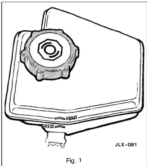
12.4 BRAKE SYSTEM BLEEDING
WARNING: GREAT CARE MUST BE EXERCISED WHEN SERVICING OR REPAIRING THE SYSTEM. AVOID SKIN/ EYE CONTACT OR INGESTION OF BRAKE FLUID. IF SKIN OR EYES ARE ACCIDENTALLY SPLASHED WITH BRAKE FLUID, RINSE THE AFFECTED AREA IMMEDIATELY WITH PLENTY OF WATER AND SEEK MEDICAL ATTENTION. IF BRAKE FLUID IS INGESTED, SEEK MEDICAL ATTENTION IMMEDIATELY.
CAUTION: Fluid must not be allowed to contact the vehicle paintwork. Remove any spilt fluid from the paintwork by rinsing away with running water. Methylated spirit (denatured alcohol) must not be used to clean the contaminated area.
CAUTION: Never use methylated spirit (denatured alcohol) for component cleaning purposes. Use only a proprietary brake cleaning fluid.
WARNING: THROUGHOUT THE FOLLOWING MAINTENANCE / SERVICE OPERATIONS, ABSOLUTE CLEANLINESS MUST BE OBSERVED TO PREVENT FOREIGN MATTER CONTAMINATING THE BRAKE SYSTEM.
12.4.1 System Bleeding - General Instructions
Use a brake bleeder bottle with a clear bleeder tube. Also recommended is a filler unit with a fill pressure of 1.0 bar. If a filler unit is not used, ensure that their is sufficient brake fluid in the reservoir throughout the bleeding procedure.
Note: Always bleed the caliper furthest away from the actuation unit first. On right hand drive vehicles, bleed in the following order: front left (FL), front right (FR), rear left (RL) and rear right (RR). On left hand drive vehicles bleed in the following order: FR, FL, RR and RL
12.4.2 System Bleeding After Brake Fluid Renewal
■ Ensure that the vehicle is standing level. Switch the ignition off.
- Check that the fluid level in the reservoir is between the min and max marks.
■ Connect the bleeder bottle tube to the relevant front caliper (see'note' above) bleeder screw(1 Fig. 1) and open the screw.
■ Bleed until new, clear, bubble free fluid is observed in the tube and then close the bleeder screw.
■ Repeat this procedure at each remaining caliper.
- With the motorrunning check brake pedal travdexcessive, check for leaks and repeat the bleed procedure.
- Fill the reservoir to the max level.
12.4.3 System Bleeding After Tandem Master Cylinder Renewal
- Ensure that the vehicle is standing level. Switch the ignition off.
- Check that the fluid level in the reservoir is between the minand max marks.
- Connect the bleeder bottle tube to the relevant front caliper (see 'note' above) bleeder screw (1 Fig. 1) and open the screw.
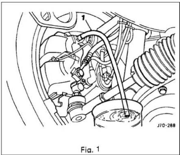
■ Actuate the brake pedal to the floor, hold for approximately two seconds and then release the pedal. Wait another two seconds and actuate the brake pedal again for further two seconds. Repeat this action 20 to 30 times until clear, bubble free brake fluid streams out.
■ With the brake pedal actuated, close the bleeder screw. Buildup fluid pressure by pumping the pedal and then open the bleeder screw. Repeat this action three to five times.
Note: If a filler unit is not used, observe the fluid level in the reservoir and top upif necessary.
■ Repeat this procedure for the remaining three calipers. (1 Fig. 1) shows the bleeder screw of the rear left caliper.
■ With the motor running check brake pedal travellf excessive, check for leaks and repeat the bleed procedure.
■ Fill the reservoir to the max level.
12.4.4 System Bleeding After Hydraulic Control Module Renewal
Hydraulic control modules are supplied pre-filled to enable the brake system to be bled in the conventional way.
■ Ensure that the vehicle is standing level. Switch the ignition off.
- Check that the fluid level in the reservoir is between the min and max marks.
- Connect the bleeder bottle tube to the relevant front caliper (see 'note' on previous page) bleeder screw (1 Fig. 1) and open the screw.
- Actuate the brake pedal full stroke, wait a moment and then release. Waittwo to three seconds and then actuate the brake pedal full stroke again. This allows the TMC to be completely re-filled with fluid.
■ Repeat 20 to 30 times until the fluid in the bleeder tube is clear and bubble free.
- With the brake pedal actuated, close the bleeder screw. Build up fluid pressure by pumping the pedal and then open the bleeder screw. Repeat this action three times.

Note: If a filler unit is not used, observe the fluid level in the reservoir and top up if necessary.
■ Repeat this procedure for the remaining three calipers.
■With the motor running check brake pedal travel. If pedal travel is excessive, check the system for leaks and repeat the bleed procedure.
■ Fill the reservoir to the max level.
12.4.5 Bleeding After Renewal of Caliper
Follow the procedure abovebut only at the affected caliper.

12.5 GENERAL FITTING INSTRUCTIONS
12.5.1 BrakFluid
WARNING: BRAKE FLUID IS CORROSIVE. EXTREME CARE MUST BETAKEN WHEN HANDLING. AVOID SKIN OR EYE CONTACT. AVOID INGESTION. IF SKIN OR EYES ARE ACCIDENTALLY SPLASHED WITH BRAKE FLUID, RINSE THE AFFECTED AREA IMMEDIATELY WITH PLENTY OF WATER AND SEEK MEDICAL ATTENTION. IF BRAKE FLUID IS INGESTED, SEEK MEDICAL ATTENTION IMMEDIATELY.
CAUTION: Fluid must not be allowed to contact the vehicle paintwork. Remove any spilt fluid from the paintwork by rinsing away with running water. Methylated spirit (denatured alcohol) must not be used to clean the contaminated area.
Cleaning Solvents
CAUTION: Never use methylated spirit (denatured alcohol) for cleaning purposes. Use only a proprietary brake cleaning fluid.

WARNING: THROUGHOUT THE FOLLOWING MAINTENANCE/ SERVICE OPERATIONS, ABSOLUTE CLEANLINESS MUST BE OBSERVED TO PREVENT GRIT OR OTHER FOREIGN MATTER CONTAMINATING THE BRAKE SYSTEM. IF THE SYSTEMS TO BE FLUSHED, USECLEAN BRAKE FLUID TO MINIMUM DOT4 SPECIFICATION. TO CLEAN BRAKE SYSTEM COMPONENTS, WASH IN A PROPRIETARY BRAKE CLEANING FLUID. REMOVE ALL TRACES OF CLEANING FLUID BEFORE REASSEMBLY. ALL BRAKESYSTEM RUBBERCON PONENTS MUST BE DIPPED IN CLEAN BRAKE FLUID AND ASSEMBLED USING THE FINGERS ONLY.
12.5.2 Hoses
- Fully release the unions (1 Fig. 1) securing each end of the hoseto the fluid pipes. Withdraw the pipe unions (1 Fig.1) from the hose ends.
- Plug the ends of the pipes (2 Fig. 1) to prevent the loss of fluid and the ingress of dirt.
■ Remove the mounting bracket locknut (3 Fig. 1) and remove the hose(4 Fig. 1). - Thoroughly clean the hose and examine for any signs of wear or damage. Renew the hose if there is any doubt about its condition. Thoroughly clean the bore of the hose using compressed air.
■ Remove all blanking plugs and fit the new hoseto the caliper / connector. Secure the hoseto the mounting bracket.
■ Beforefully tightening the locknut, ensure that the hose is neither kinked nor twisted.
■ Bleed the brakes.
12.5.3 Pipes
■ Fully release the pipe unions (1 Fig. 1).
■ Withdraw the pipe (5 Fig. 1) from the vehicle. Plug the pipes (2 Fig. 1) to prevent the loss of fluid or the ingress of dirt. Thoroughly clean and examine the pipe for signs of damage or deterioration. Renew the pipe if there is any doubt about its condition.
- Thoroughly clean the bore of the pipe using compressed air.
■ Remove all blanking plugs and fit the new pipe to the vehicle. Secure the pipe to the body.
■ Bleed the brakes.

12.6 REAR WHEEL SPEED SENSOR-RENEW
SRO 70.60.04
- Drivethe vehicle onto a ramp or raise the back and support on two stands.
- Cut and remove the ratchet strap securing the speed sensor harness to the brake hose.
■ Undo and remove the speed sensor to hub carrier securing bolt (Fig. 1).
■ Remove the speed sensor from the hub carrier and allow it to hang free, forward of the 'A' frame.
- Open both rear doors and displace the rear seat cushion from the seat pan brackets. Reposition the rear seat cushion forwards.
- Push the seat belts/buckle through the seat cushion slots and remove the rear seat cushion from the vehicle.
■ Displacethe RH side of the seat pan sound proofing (1 Fig. 2) to gain access to the speed sensor harness (2 Fig. 2).
■ Displace the speed sensor harness grommet (3 Fig. 2) from the seat pan aperture.
- Feed the speed sensor harness through the seat pan aperture and disconnect the multi-plug (4 Fig. 2).
- Position the new speed sensor harness and connect the multi-plug.
■ Feed the speed sensor harness through the seat pan aperture to hang free below the vehicle.
■ Refit and fully seat the speed sensor harness grommet to the seat pan aperture.
■ Reposition the seat pan sound proofing to its original position.
- Position the rear seat cushion and feed the seat belt / buckles through the slots.
- Locate the rear seat cushion into the seat pan brackets (5 Fig. 2).
■ Stow the seat belts/buckles.
■ Position the speed sensor harness rearwards over the 'A' frame and locate into the hub carrier.
- Fit and tighten the speed sensor to hub carrier securing bolt.
- Secure the speed sensor harness to the brake hose using a ratchet strap. Trim the ratchet strap.

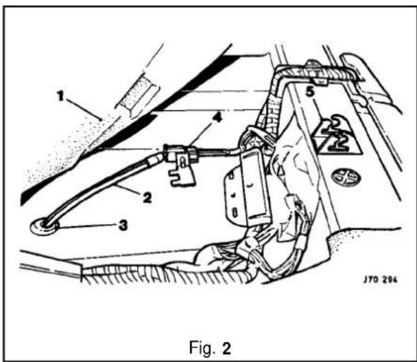

12.7 HYDRAULICCONTROL MODULE- RENEW
SRO 70.60.18
70.60.19
Refer to Section 12.4, Brake System Bleeding before carrying out this procedure. Pay particular attention to the warnings and cautions relating to brake fluid, cleanliness and cleaning materials.
Note: The illustration shows the hydraulic control module of a 6cyl, vehicle with traction control. Hydraulic control modules on non-traction control vehicles have only three outlet ports. Apart from this, the removal procedure is the same for all vehicles.
■ Raise the vehicle.
- Displace the bleederscrew dust cap of the front LH caliper. The dust cap will remain captive on the bleed screw.
■ Connect a bleeder tube and bottle to the bleeder screw (1 Fig. 1) and open the bleeder screw.
- Fit a brake pedal hold-down tool (JDS-9013) between the brake pedal and the steering wheel. Adjust the tool to operate the brake pedal 60mm down. This operation is necessary to prevent fluidoss from the reservoir through disconnected brake pipes.
■ Re-tighten the front LH caliper bleeder screw. Disconnect the bleeder tube from the bleeder screw and remove the tube and bottle. Refit the bleeder screw dust cap.
- Undo the securing bolt of the multi -plug connector(1 Fig. 2). The bolt will remain captive. Disconnect the multi -plug connector and reposition safely.
■ Place absorbent material underneath the hydraulic control module to absorb any spillages.
■ Undo the tandem master cylinder (TMC) brake pipe gland nuts (2 Fig.2) and disconnect the brake pipes.
■ Fit plugs immediately to the brake pipes and the hydraulic control module to prevent fluidoss.
■ Undo the rear brake pipe gland nuts (3 Fig. 2) at the pressure conscious reducing valves (PCRV4 Fig.2). Remove the rear brake pipes.
Note: Take necessary steps to prevent rotation of the PCRVswhen removing the rear brake pipes.
- Fit plugs immediately to the brake pipes and the PCRVsto prevent fluid loss.
■ Undo and remove the PCRVsFit plugs immediately to the PCRVsand the hydraulic control module. - Place PCRVs aside to be fitted later to the new hydraulic control module.
■ Undothe front brake pipe gland nuts (5 Fig.2) and remove the front brake pipes.
■ Fit plugs immediately to the brake pipes and the hydraulic control module to prevent fluidloss.
■ Undo and removethe three securing nuts (6 Fig. 2) and remove the hydraulic control module.


■ Remove the absorbent material and clean the mounting bracket and surrounding area.
- Fit and align a new hydraulic control module to the mounting bracket. Ensure that the mounting cup tangs fully engage the bracket slots.
- Fit and tighten the securing nuts(6 Fig. 1).
■ Place absorbent material underneath the hydraulic control module to absorb any spillages.
■ Connect the front hydraulic brake pipes (5 Fig. 1) to the hydraulic control module, removing plugs immediately prior to connection. Tighten the gland nuts.
- Fit the PCRVs(4 Fig. 1) to the hydrauliccontrol module, removing plugs immediately prior to connection. Tighten the PCRVs.
■ Connect the rear hydraulic brake pipes (3 Fig. 1) to the PCRVs, removing the plugs immediately prior to connection. Tighten the gland nuts.
Note: Take necessary steps to prevent rotation of the PCRVs when fitting the rear brake pipes.
- Connect the TMC hydraulic brake pipes (2 Fig. 1) to the hydraulic control module, removing the plugs immediately prior to connection. Tighten the gland nuts.
■ Removethe absorbent material and cleanthesurrounding area.
■ Reposition and connect the multi-plug connector. Tighten the securing bolt(1 Fig. 1).
■ Ensure that all fixings are torque tightened to specified tolerances.
■ Release the brake pedal hold-down tool and remove.
■ Bleed the brake system (referto sub-section 12.4.4).
■ Examine the hydraulic control module for leaks.


12.8 PRESSURE CONSCIOUS REDUCING VALVES- RENEW
SRO 70.60.21
Refer to Section 12.4, Brake System Bleeding before carrying out this procedure. Pay particular attention to the warnings and cautions relating to brake fluid, cleanliness and cleaning materials.
Note: The illustration shows the hydraulic control module of a 6cyl. vehicle with traction control. Hydraulic control modules on nontraction control vehicles have only three outlet ports. Apart from this, the removal procedure is the same for all vehicles.
■ Raise the vehicle.
- Displacethe bleeder screw dust cap of the front LHcaliper. The dust cap will remain captive on the bleed screw.
- Connect a bleeder tube and bottle to the bleeder screw (1 Fig. 1) and open the bleeder screw.
- Fit a brake pedal hold-down tool (JDS-9013) between the brake pedal and the steering wheel. Adjust the tool to operate the brake pedal 60mm down. This operation is necessary to prevent fluidloss from the reservoir through disconnected brake pipes.
■ Re-tighten the front LHcaliper bleeder screw. Disconnect the bleeder tube from the bleeder screw and remove the tube and bottle. Refit the bleeder screw dust cap.
- Place absorbent material underneath the hydraulic control module to absorb any spillages.
■ Undo the rear brake pipe gland nuts (1 Fig. 2) at the pressure conscious reducing valves (PCRVs|2 Fig. 2). Remove the rear brake pipes.

Note: Take necessary steps to prevent rotation of the PCRVs when removing the rear brake pipes.
- Fit plugs immediately to the brake pipes and the PCRVsto prevent fluid loss.
■ Undo and removethe PCRVs. Fit plugs immediately to the PCRVs and the hydraulic control module.
■ Clean the surrounding area.
■ Fit new PCRVs to the hydraulic control module, removing plugs immediately prior to connection. Tighten the PCRVs.
■ Connect the rear hydraulic brake pipes to the PCRVs, removing the plugs immediately prior to connection. Tighten the gland nuts.
Note: Take necessary steps to prevent rotation of the PCRVs when fitting the rear brake pipes.
■ Removethe absorbent material and clean the surrounding area.
■ Ensure that all fixings are torque tightened to specified tolerances.
- Release the brake pedal hold-down tool and remove.
■ Bleed the brake system (refer to sub-section 12.4.4).
■ Examine the hydraulic control module for leaks.
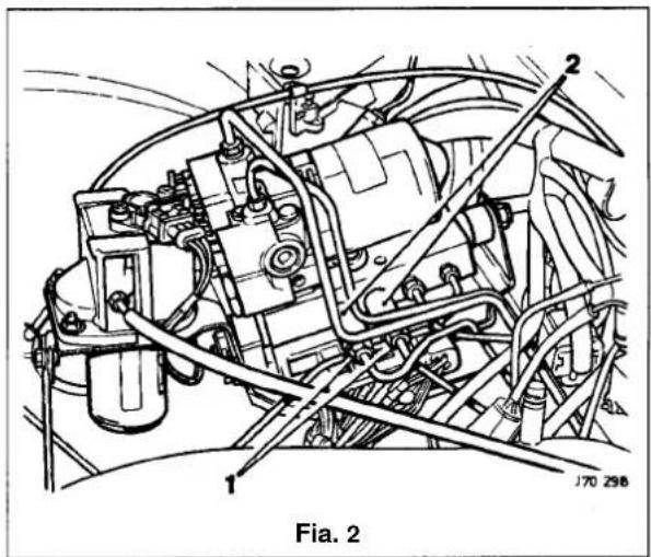


12.9 ABS / TCCM - RENEW
SRO 70.60.02
70.60.20
Refer to Section12.4, Brake System Bleeding before carrying out this procedure. Pay particular attention to the warnings and cautions relating to brake fluid, cleanliness and cleaning materials.
- Remove the hydraulic control module. Refer to sub-section 12.7, SROs 70.60.18 & 19.
- Disconnect the pump electric motor to ABS / TCCM multi-plug (1 Fig 1).
■ Undo and remove two securing screws and remove the ABS/TC CM. - Clean the mating faces of the hydraulic control module and the new ABS /TC CM. Fit and tighten two securing screws.
- Re-connect the pump electric motor to ABS/TCCM multi-plug.
■ Refit the hydraulic control module. Refer to sub-section 12.7, SROs 70.60.18 & 19.


SECTION CON TENTS
| Sub-Section | Title | SRO | Page |
| I to V | Preliminary Pages | i to v | |
| 13.1 | General Description | 1 | |
| 13.2 | Door and Fuel Filler Flap | 2 | |
| 13.2.1 | Doors. Description | 2 | |
| 13.2.2 | Front Door Trim Pad Veneer Panel. Renew | 76.47.11 | 2 |
| 13.2.2 | Rear Door Trim Pad Veneer Panel. Renew | 76.47.12 | 2 |
| 13.2.3 | Rear Door Upper Trim Pad. Remove For Access and Refit | 76.34.05/90 | 3 |
| 13.2.4 | Rear Door Upper Trim Pad, Renew | 76.34.05 | 3 |
| 13.2.5 | Rear Door Window Lift Switch Veneer Panel. Renew | 76.47.34 | 3 |
| 13.2.6 | Rear Door Lower Trim Pad, Remove for Access and Refit | 76.34.06/90 | 4 |
| 13.2.7 | Rear Door Lower Trim Pad, Renew | 76.34.06 | 4 |
| 13.2.8 | Rear Door Armrest. Renew | 76.34.23 | 5 |
| 13.2.9 | Rear Door Pocket, Renew | 76.34.28 | 5 |
| 13.2.10 | Front Door Upper Trim Pad, Renew | 6 | |
| 13.2.11 | Front Door Lower Trim Pad, Renew | 6 | |
| 13.2.12 | Door Lock Barrel, Renew | 6 | |
| 13.2.13 | Front or Rear Door Lock Striker, Renew | 6 | |
| 13.2.14 | Front or Rear Door Outer Handle Operating Rod, Renew | 6 | |
| 13.2.15 | Front Armrest, Renew | 7 | |
| 13.2.16 | Front or Rear Armrest Support. Renew | 7 | |
| 13.2.17 | Front Door Pocket. Renew | 7 | |
| 13.2.18 | Fuel Filler Flap, Description | 8 | |
| 13.2.19 | Filler Flap and Hinge, Renew | 8 | |
| 13.2.20 | Filler Cap Retention Magnet. Renew | 8 | |
| 13.2.21 | Filler Flap Latching Assembly, Renew | 8 | |
| 13.3 | Passenger Compartment | 9 | |
| 13.3.1 | Console Assembly, Remove for Access and Refit | 76.25.01/90 | 9 |
| 13.3.2 | Console Assembly, Renew (Daimler/ VDP) | 76.25.01/50 | 10 |
| 13.3.3 | Console Assembly, Remove for Access and Refit (Daimler/ VDP) | 76.25.01/91 | 12 |
| 13.3.4 | Console Assembly, Renew | 76.25.01 | 13 |
| 13.3.5 | Console Rear Extension Finisher, Renew | 76.25.04 | 14 |
| 13.3.6 | Console Rear Extension. Renew | 76.25.05 | 14 |
| 13.3.7 | Selector Trim Finisher, Renew (3.2 Liter) | 76.25.07 | 14 |
| 13.3.8 | Selector Trim Finisher, Renew (4.0 Liter, 4.0 Liter SC and 6.0 Liter) | 76.25.07 | 15 |
| 13.3.9 | Mode Switch Finisher, Renew | 76.25.09 | 15 |
| 13.3.10 | Radio Console, Renew | 76.25.15 | 16 |
| 13.3.11 | Console Glove Box, Renew | 76.25.16 | 17 |
| 13.3.12 | Console Glove Box Lid, Renew | 76.25.18 | 18 |
| 13.3.13 | Console Glove Box Lid Hinge, Renew | 76.25.20 | 19 |
| 13.3.14 | Cupholder Trim Panel, Renew | 76.25.21 | 19 |
| 13.3.15 | Cupholder, Renew | 76.25.22 | 20 |
| 13.3.16 | Cupholder Latch, Renew | 76.25.23 | 20 |
| 13.3.17 | Fascia Board, Renew | 76.46.01 | 21 |
| 13.3.18 | Fascia Board. Remove for Access and Refit | 76.46.01/90 | 24 |


SECTION CONTENTS
| Sub-Section | Title | SRO | Page |
| 13.3.19 | Underscuttle Pad. Drivers Side. Remove for Access and Refit | 76.46.1 1/90 | 26 |
| 13.3.20 | Underscuttle Pad. Passenger Side. Remove for Access and Refit | 76.46.15/90 | 26 |
| 13.3.21 | Fascia Closing Panel - Passenger Side. Renew | 76.46.27 | 27 |
| 13.3.22 | Fascia Closing Panel - Drivers Side. Renew | 76.46.28 | 27 |
| 13.3.23 | Fascia Center Veneer Panel. Renew | 76.47.06 | 28 |
| 13.3.24 | Console Finisher Veneer Panel. Renew | 76.47.26 | 29 |
| 13.3.25 | Console Ashtray Lid Veneer Panel. Renew | 76.47.27 | 30 |
| 13.3.26 | Console Ashtray Surround Veneer Panel. Renew | 76.47.28 | 30 |
| 13.3.27 | Console Rear Extension Veneer Panel. Renew | 76.47.30 | 30 |
| 13.3.28 | Console Ashtray, Renew | 76.67.18 | 31 |
| 13.3.29 | Steering Column Upper cowl. Renew | 76.46.02 | 32 |
| 13.3.30 | Steering Column Lower cowl. Renew | 76.46.03 | 32 |
| 13.3.31 | Steering Column Switchgear Mounting Bracket. Renew | 76.46.33 | 33 |
| 13.3.32 | 'A' Post Lower Trim Pad. Renew | 76.13.30 | 35 |
| 13.3.33 | Rear Quarter Upper Trim Pad. Renew | 35 | |
| 13.3.34 | 'B' Post Upper Trim Pad. Renew | 35 | |
| 13.3.35 | 'B' Post Lower Trim Pad. Renew | 35 | |
| 13.3.36 | Handbrake Lever Trim. Renew | 35 | |
| 13.3.37 | Combined Grab Handle and Coat Hanger Hook. Renew | 35 | |
| 13.3.38 | Sun Visor Assembly RH or LH. Renew | 36 | |
| 13.3.39 | Roof Lining (Headlining). Description | 37 | |
| 13.3.40 | Roof Lining. Renew | 37 | |
| 13.4 | Trunk | 38 | |
| 13.4.1 | Trunk. Description | 38 | |
| 13.4.2 | Trunk Side Liner - Left Hand. Renew | 76.19.22 | 39 |
| 13.4.3 | Trunk Side Liner - Right Hand. Renew | 76.19.23 | 39 |
| 13.4.4 | Trunk Floor Carpet. Renew | 76.19.30 | 39 |
| 13.4.5 | Trunk Front Liner, Renew | 76.19.31 | 39 |
| 13.4.6 | Trunk Seal Retainer, Renew | 76.19.44 | 40 |
| 13.4.7 | Trunk Lid Striker, Adjust | 40 | |
| 13.4.8 | Trunk Lid Liner, Renew | 40 | |
| 13.4.9 | Trunk Seal Retainer, Renew | 40 | |
| 13.4.10 | Trunk Lid Lock Striker, Renew | 40 | |
| 13.4.11 | Trunk Lid Lock Barrel. Renew | 40 | |
| 13.4.12 | Trunk Lid Lock Mechanism, Renew | 41 | |
| 13.3.13 | Trunk Lid Gas Strut. Adjust. Renew | 41 | |
| 13.4.14 | Trunk Lid Hinge, Renew | 41 | |
| 13.4.15 | Trunk Rear Liner, Renew | 41 | |
| 13.5 | Hood | 42 | |
| 13.5.1 | Hood Description | 42 | |
| 13.5.2 | Plenum Chamber Finisher, Renew | 76.10.01 | 42 |
| 13.5.3 | Hinge. Renew | 42 | |
| 13.5.4 | Gas Strut, Renew | 43 | |
| 13.5.5 | Hood Lock RH or LH, Renew | 43 |

SECTION CONTENTS
| Sub-Section | Title | SRO | Page |
| 13.5.6 | Hood lock Control Cable RH or LH, Renew | 43 | |
| 13.5.7 | Hood Striker Assembly, Renew | 43 | |
| Hood lock Release Handle. Renew | 43 13.5.8 | ||
| 13.6 | Glazing (Fixed) | 44 | |
| 13.6.1 | Glazing (Fixed). Description | 44 | |
| 13.6.2 | Interior Mirror, Renew | 44 | |
| 13.6.3 | Sun Visor Mirror Assembly, Renew | 44 | |
| 13.6.4 | Exterior Mirror, Renew | 44 | |
| 13.6.5 | Exterior Mirror Glass, Renew | 44 | |
| 13.7 | Carpets | 45 | |
| 13.7.1 | Carpets, Description | 45 | |
| 13.7.2 | Removal of Stains – General Information | 45 | |
| 13.7.3 | Powder Cleaning – Removal of Small Spillage Stains | 45 | |
| 13.7.4 | Spot Cleaning – Localized Stains | 46 | |
| 13.7.5 | Carpet Cleaning and Stain Removal Materials | 47 | |
| 13.7.6 | Repair of Damaged Carpet | 47 | |
| 13.8 | Seating and Seat Belts | 48 | |
| 13.8.1 | Seating, Description | 48 | |
| 13.8.2 | Front Manual Seat, Renew | 48 | |
| 13.8.3 | Front Seat (Power Operated), Renew | 48 | |
| 13.8.4 | Front Seat Head Restraint (Power Operated), Renew | 49 | |
| 13.8.5 | Front Seat Head Restraint (Power Operated), Renew | 49 | |
| 13.8.6 | Rear Seat Cushion. Renew | 49 | |
| 13.8.7 | Rear Seat Squab, Renew | 49 | |
| 13.8.8 | Seat Belts, Description | 50 | |
| 13.8.9 | Emergency Locking Retractor/ Automatic Locking Retractor Seat Belts | 50 | |
| 13.8.10 | Tear loop Seat Belts, Description | 51 | |
| 13.8.11 | Front Seat Belt Buckle Unit, Renew | 52 | |
| 13.8.12 | Front Seat Belt, Renew | 52 | |
| 13.8.13 | Rear Inertia Seat Belt, Renew | 52 | |
| 13.8.14 | Rear, Center, Static Seat Belt, Renew | 53 |
I. SERVICE TOOLS & EQUIPMENT
| Illustration Jaguar | Number Description Notes | ||
| not illustrated JD | 188 | Underscuttle pad securing clip removal tool | SRO 76.46.1 1/90 and SRO 76.46.15/90 |
| not illustrated JD | 202 | Fasciacenter vent removal tool | SRO 76.46.06 |
II. TORQUE TIGHTENING SPECIFICATIONS
| Fixing Tightening Torque | (Nm) |
| Fascia | |
| Instrument pack to support panel | 1.8 |
| Fascia to support bracket | 22 – 28 |
| Fascia to console | 3 |
| Tunnel bracket to body | 22 – 28 |
| Bolster to tunnel bracket | 1.5 |
| Instrument pack to fascia | 3.0 |
| Strut to fascia | 2.0 |
| Fascia support strut to body | 7 – 10 |
| CPU bracket to fascia | 5 – 7 |
| Fascia demister bracket to fascia | 1.5 |
| Fascia and air con. location to body | 1.0 |
| Air dist. box duct to air dist. box | 1.0 |
| Airbag carrier mounting bracket to fascia | 5 – 7 |
| Instrument pack support bracket to fascia | 5 – 7 |
| Airbag bracket to fascia | 2.0 |
| Air dist. box to fascia | 2.0 |
| Inst. pack support bracket to fascia | 5 – 7 |
| Fascia assembly to body | 22 – 28 |
| Airbag door brackets to fascia | 5 – 7 |
| Airbag door bracket to fascia and strut | 4.0 |
| Airbag door bracket to door frame assembly | 4.0 |
| Hood | |
| Hood lock to body | 7 – 10 |
| Hood buffer assembly | 7 – 10 |
| Gas strut - ball pinto weld nut | 7 – 10 |
| Hood lever | 5 – 7 |
| Clamp - hood adjust cable | 6 – 8 |
| Interior | |
| Sun Visor fixings | 1.8 |
| Sunblind to parcel shelf | Tighten to prevailing torque |
| Sunblind bezel assembly | 1.0 |
| Coat hook | 3.0 |
| Fixing | Tightening Torque(Nm) |
| Seat belts | |
| Front tear loop belt buckle to bracket fixing | 30 - 40 |
| Front belt buckle to bracket fixing | 30 - 40 |
| Front belt reel bracket to body fixing | 30 - 40 |
| Front belt anchor fixing | 30 - 40 |
| Front belt upper guide fixing | 7 - 10 |
| [Height adjuster to 'B' post screws | 23 - 27 |
| Height adjuster to seat belt anchor retaining nut | 30 - 40 |
| Rear inertia belt anchor fixing | 30 - 40 |
| Rear inertia belt bracket to body fixing | 30 - 40 |
| Rear inertia belt reel securing bracket to body fixing | 30 - 40 |
| Rear inertia / static belt buckle bracket to body fixing | 30 - 40 |
| Rear static belt/ inertia buckle bracket to body fixing | 30 - 40 |
| Sunroof | |
| Sunroof frame to roof | 4 - 5 |
| Sunroof to frame | 4 - 5 |
| Trunk | |
| Compact disc autochanger bracket to body | 9 - 11 |
| Battery clampto tray | 7 - 10 |
| Warning triangle lower bracket to trunk lid inner panel | 1.5 |
| Trunk lock barrel to lid | 4 - 5 |
| Trunk latch to lid and striker to body | 7 - 10 |
| Trunk latch actuator to bracket | 7 - 10 |
| Trunk latch actuator mounting to lid | 7 - 10 |
| Electrical carrier box to body | 5 - 7 |
| Loadfloor support block to body | 9 - 11 |
| Trunk seal retainer to body | 9 - 11 |
- SERVICE MATERIALS
| Description | Uses | Notes |
| 'Fibrefresh' Carpet Shampoo | Cleaning of water-based stains from carpets | |
| '1001' Foam Shampoo | Cleaning of water-based stains from carpets | |
| 'Novatreat' | Cleaning of water-based stains from carpets | |
| 'Genklene' (Trichloroethane) | Cleaning of grease or oil based stains from carpets | |
| 'Spot Remover' | Cleaning of grease or oil based stains from carpets |
13.1 GENERAL DESCRIPTION
This section covers the following areas of the vehicle body:
Battery cover
- Carpets - passenger compartment, trunk
- Console – including radio, glovebox
- Doors – frames, sealing, locks, trim, glazing
Fascia
- Fuel filler flap assembly
Footrest
- Hood - liners, gas strut, locking,
- Illuminated sunvisor - inc mirror
- Interior trim-trim pads, finishers, veneers
○ Mirrors - internal, external
- Rear parcel tray
- Roof console
- Roof lining (headlining)
- Seats - front, rear
- Seat belts - front, rear
○ Sliding roof
- Steering column cowl
- Underscuttle pad
Refer to AppendixA4 - Body Systems& Body Repair for information relating to crash-damage repairs and to the following external components: exterior trim, bumpers, windscreen and rear screen, closures and sealing.
Refer to Section 15, Electrical for details of the following motors and solenoids: driver's and interior mirrors, window lift, sunroof, seat / headrest and locking mechanisms (doors, trunk and filler cap).
Refer to Section 15, Electrical and Electrical Diagnostic Manual (EDM) for details of the passenger and driver airbags.


13.2 DOORS AND FUEL FILLER FLAP
13.2.1 Doors, Description
Doors are of welded, mild steel frames welded to the door panels; sponge rubber primary and secondary seals are mounted on the doors. Internal insulation is provided by a foam water shedder attached to the door by press fitting and double-sided adhesive tape.
Front and rear door armrests are attached to supports riveted to each door frame; the attaching screws are fitted with access covers. Upper and lower trim pads and a door pocket are attached to each of the doors by clips and screws. multi-plug connectors are used to provide a means of connecting the guard lamps, window lift switches and loudspeakers, external mirror and regulator (front doors only), which are housed within the doors.
Central locking is provided subject to market variations: Dead Locking for UK/Europe and Driver only unlock for N America. Door locks are eight disc, bayonet fixing, barrels with integral lock/unlockswitches. Keys include 'in-key' transponders which are programmed to the vehicle via the Jaguar Diagnostic System also operate the engine immobilisation system.
CAUTION: When removing the door panel water shedder, a foam membrane attached to each door panel by a combination of pressfitting (upper area) and by double-sided tape (bottom area) is important that the shedder is refitted correctly to maintain the water seal.
It is advisable not to disturb the bottom (taped) portion of the water shedder unless absolutely necessary – it is possible to unclip the top of the shedder and bend it over to gain access to the inner panel.
If it is necessary to disturb the bottom attachment, eg to remove the water shedder from the door panel, the existing water shedder must be discarded and a new one fitted to ensure that the seal is maintained. On refitting, the new water shedder should be pressed onto the door panel at the top and then the adhesive tape backing strip peeled off to enable the shedder to be pressed home at the bottom.
13.2.2 front and Rear Door Trim Pad Veneer Panel, Renew
SRO 76.47.11
76.47.12
■ Reposition the inner door handle. See Fig. 1.
- Remove the inner handle escutcheon plate blanking plate.
■ Undo and remove the inner handle escutcheon plate securing screw.
■ Remove the plate and gasket.
■ Carefully Undo and remove the veneer panel.
■ Undo and remove the retaining clip securing screws.
■ Remove the retaining clip assemblies.
■ Place the veneer panel aside.
■ Place the new veneer panel to the front.
• Fit the retaining clip assemblies.
■ Fit and tighten the retaining clip securing screws.
■ Fit and fully seat the veneer panel to the door.
■ Reposition the inner door handle.
■ Fit the gasket and plate over the inner door handle.
■ Fit and tighten the escutcheon plate securing screw.
■ Refit the blanking plate.

Fig. 1

13.2.3 Rear Door Upper Trim Pad - Remove For Access And Refit
SRO 76.34.05/90
■ Remove the reardoor trim pad veneer panel, see sub-section 13.2.2.
- Undo and remove the uppetrim panel securing screws.
■ Lift to release the panel from the door mounting and remove the panel.
■ Fit the trim pad and fully seat on the door mounting position.
■ Fit and tighten the trim pad securing screws.
■ Refit the veneer panel.
13.2.4 Rear Door Upper Trim Pad, Renew
SRO 76.34.05
■ Removethe rear door trim pad veneer panel, see sub-section 13.2.2.
■ Undo and remove the upper-trim panel securing screws.
■ Lift the panel to release from the door mounting and remove the panel.
■ Undo and remove the chrome strip securing screws.
■ Remove the chrome strip.
■ Undo and remove the top channel securing nuts.
■ Displace and remove the top channel assembly.
■ Placethe trim pad aside.
■ Place netwim pad to the front.
■ Fit the upper channel to the trim pad.
■Fit and tighten the channel securing nuts.
■ Fit the chrome strip.
■ Fit and tighten the chrome strip securing screws.
■ Fit the trim pad and fully seat on the door mounting position.
■ Fit and tighten the trim pad securing screws.
■ Refit the veneer panel.


13.2.5 Rear Door Window Lift Switch Veneer Panel, Renew
SRO 76.47.34
■ Displace and remove the window lift assembly end cover trim pad, Fig. 2.
- Undo and removetheveneer panel to switch assembly securing screw.
■ Displace and remove the veneer panel from the forward securing clip.
- Place panel aside.
■ Fit and fully seat new veneer panel to the forward securing clip.
■ Fit andfully tighten the panel securing screw.
■ Fit and fully seat the switch assembly end trim pad.
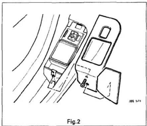

13.2.6 Rear Door lower Trim Pad - Remove For Access And Refit
SRO 76.34.06/90
- Remove the rear door armrest, see sub-section 13.2.8.
- From inside the door pocket, release the puddle lamp (1 Fig. 1) securing quarter turn fastener.
- Disconnect the muplugs(1Fig.2) and removethe lamp.
- Carefully displace the trim pad (2 Fig. 1) from the door retaining clips.
■ Displacement pad from the upper retaining tang (3 Fig. 1). - Disconnect the door speakermulti-plug(2 Fig. 2) and the window lift switch multi-plug (3 Fig. 2).
- Feed the lamp harness through the trim pad and lower the trim pad assembly.
■ Position theim pad to the vehicle.
■ Feed the puddle lamp harness through the trim pad.
- Connect the window lift switch and speaker multi-plugs.
- Locate theim pad upper retaining tang.
■ Fit and fully seat the trim pad retaining clips.
- Place the puddle lamp to position.
■ Connect the lamp multiugs.
■ Fit and align the puddle lamp to the door pocket and secure with the lamp securing quarter turn fastener.
- Refit the armrest.

13.2.7 Rear Door Lower Trim Pad, Renew
SRO 76.34.06
■ Remove the rear door armrest, see sub-section 13.2.8.
■ From inside the door pocket, release the puddle lamp (1 Fig. 1) securing quarter turn fastener.
- Disconnect lamp multi-plugs (1 Fig. 2) and remove lamp.
- Displace thetrim panel (2 Fig. 1) from door retaining clips.
■ Displace trim pad from the upper retaining tang (3 Fig. 1).
■ Disconnect the door speaker multi-plug(2 Fig. 2) and the window lift switch multi-plug (3 Fig. 2).
■ Feed the lamp harness through the trim pad and lower the trim pad assembly.
■ Remove the rear door pocket, see sub-section 13.2.9.
■ Displace and remove the retaining clips and remove the trim..
- Place the new dotrim pad to the front.
■ Fit and fully seat the trim pad retaining clips.
■ Refit the rear door pocket.
■ Position them pad to the vehicle.
■ Feed the puddle lamp harness through the trim panel.
- Connect the window lift switch and speaker multi-plugs.
■ Locate thetrim pad upper retaining tang.
■ Fit and fully seat the trim pad retaining clips.
■ Place the puddle lamp to position.
- Connect the lamp multi-plugs.
■ Fit and align the puddle lamp to the door pocket and secure with the lamp securing quarter turn fastener.
■ Refit the armrest.

13.2.8 Rear Door Armrest, Renew
SRO 76.34.23
- Displace and remove the armrest securing screw hole plastic finisher covers(1 Fig. 1).
■ Undo and remove the armrest securing screws (2 Fig. 1) and remove the armrest assembly.
■ Remove the armrest screw hole plastic finishers (3 Fig. 1).
■ Undo and remove the chrome finisher securing screws.
■ Undo and remove the armrest inner black finisher securing screws.
■ Displace and remove the finisher.
■ Place the armrest aside.
■ Place the new armrest to the front.
■ Fit and align the inner trim finisher.
- Fit and tighten the finisher securing screws.
■ Fit and align the armrest chrome finisher.
■ Fit and tighten the finisher securing screws.
■ Fit and seat armrest securing screw hole plastic finishers.
■ Position the armrest assembly. Fit and tighten the armrest securing screws.
■ Fit and seat the armrest screw hole plastic finisher covers.

13.2.9 Rear Door Pocket, Renew
SRO 76.34.28
■ Remove the rear door armrest, see sub-section 13.2.8.
■ Remove the lowerim pad, see sub-section 13.2.6.
■ Undo and remove the rear door pocket to trim pad securing screws (Fig. 2). Remove the door pocket.
■ Displace and removethe rear window lift switch assembly end cover trim pad (Fig. 3).
■ Undo and remove the veneer panel to switch assembly securing screw (Fig. 3).
■ Displace and remove the veneer panel from the forward securing clip (Fig. 3).
■ Undo and remove the switch assembly securing screws / nuts (Fig. 3).
■ Displace and remove the switch assembly.
■ Undo and remove the speaker securing screws and remove the speaker.
■ Displace and remove the speaker grille.
■ Place the door pocket aside.
■ Place new rear door pocket to the front.
■ Fit and fully seat the speaker grille.
■ Position the speaker and fit the speaker securing screws.
■ Fit and align the window lift switch assembly.
■ Fit and tighten the switch assembly securing screws / nuts.
■ Fit arfolly seat the veneer panel to the front securing clip.
■ Fit and tighten the veneer panel securing screw.
■ Fit anfully seat the switch end covertrim pad.
- Position the door pocket to lower trim pad and fit and tighten the door pocket securing screws.
■ Refit the door lower trim pad.
■ Refit the rear door armrest.


13.2.10 Front Door Upper Trim Pad, Renew
■ Disconnect vehicle battery ground lead.
■ Remove the front door veneer panel.
■ Remove the upper trim pad securing clip and screws.
■ Lift the trim pad to release it from the door and remove the inner waist rail seal.
■ To refit, carry out reversal of the above procedure.
13.2.11 Front Door lower Trim Pad, Renew
■ Disconnect vehicle battery ground lead.
- Remove armrest.
■ From inside door pocket, release guard retainer, disconnect multi -plug and remove lamp.
- Carefully prise the trim pad away from the door and release from the upper retainer.
- With the trim pad moved for access, disconnect loudspeaker and window lift switch multi-plugs.
■ Feed guard lamp harness through aperture and place trim pad on a clean workbench.
■ Remove front door pocket and trim pad retainers.
■ To refit, carry out reversal of the above procedure. Check the trim pad retainers for damage before refitting.

13.2.12 Door lock Barrel, Renew
■ Disconnect vehicle battery ground lead.
■ Remove the door trim veneer, door upper trim pad, door lower trim pad and door handle.
■ Remove the handle assembly to a clean workbench.
■ Remove the lock barrel from its bayonet type mounting.
- Carefully remove the barrel components noting the order and position if reassembly is required.
■ To refit, carry out reversal of the above procedure, ensuring that the components are lightly greased.
13.2.13 Front or Rear Door Lock Striker, Renew
■ Note position of striker before removal.
■ Remove two screws attaching striker to pillar.
■ Remove striker from pillar.
■ To refit, carry out reversal of the above procedure, ensuring that the striker is correctly aligned with the door lock before final torque tightening.
13.2.14 Front or Rear Door Outer Handle Operating Rod, Renew
■ Disconnect vehicle battery ground lead.
■ Remove the door trim veneer, door upper trim pad, door lower trim pad.
■ Disengage the handle operating rod retaining clip and free the rod from the operating pivot.
- Allow the latch levertocontact the release mechanism, reposition the operating rod and replace the retaining clip.
- Check that the setting is correct by operating the door mechanism.
• To refit, carry out reversal of the above procedure.


13.2.15 Front Armrest, Renew
■ Disconnect vehicle battery ground lead.
- Remove access covers to armrest fixings.
- Remove screws securing armrest to support bracket.
■ Remove armrest and remove fixing screw inserts from armrest.
■ To refit, carry out reversal of the above procedure.
13.2.16 Front or Rear Armrest Support, Renew
■ Disconnect vehicle battery ground lead.
■ Remove door armrest.
■ Remove lower trim pad from door.
- Drill outrivets and remove retainingscrewsfromfront and rear armrest support brackets.
■ Remove drilling debris and swarf.
■ Make good any damage to body finish caused by drilling; use zinc primer and body colour.
■ To refit, carry out reversal of the above procedure.

13.2.17 Front Door Pocket, Renew
■ Disconnect vehicle battery ground lead.
■ Remove armrest.
■ Remove lower trim pad and place on a clean workbench.
■ Remove fixings and remodeor pocket.
■ Remove veneer panel, switch assembly, loudspeaker and loudspeaker grille.
■ To refit, carry out reversal of the above procedure.
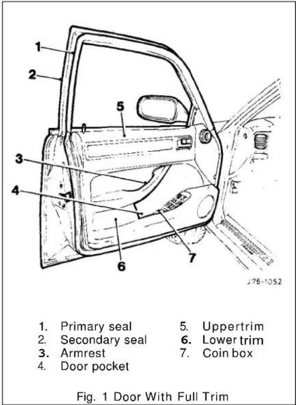


13.2.18 Fuel Filler Flap, Description
The fuel filler flap comprises a hinged flap attached to the body decking panel by two M5 nuts; the flap incorporates a rubber buffer, snap -in striker, hinge spring and the fuel cap stowage magnet. The rubber fuel bowl moulding is attached via a steel armature to the body reinforcement panel by five M5 nuts and is retained at the filler neck by a clip. The mating drain tube is fitted with an internal filter.
The fuel filler flap latch mechanism attached to the fuel bowl armature by two M5 nuts, includes a lockingpin and actuator which are both serviceable items. The latch actuator operates independently from the central locking system; it is driven directly by the security and locking control module. Locking of the fuel filler flap is achieved only by operation of the key or by the remote rf transmitter.
13.2.19 Filler Flap and Hinge, Renew
■ Disconnect vehicle battery ground lead.
- With filler cap open, remove hinge securing screws, fuel filler cap and remove flap and hinge assembly.
■ To refit, carry out reversal of the above procedure.
13.2.20 Filler Cap Retention Magnet, Renew
- Disconnect vehicle battery ground lead.
■ With filler flap open, use a blunt flat bladed implement and remove the magnet assembly.
CAUTION: Take care not to damage paintwork.
■ To refit, carry out reversal of the above procedure.
13.2.21 Filler Flap latching Assembly, Renew
■ Disconnect vehicle battery ground lead.
■ Depress the latching assembly retaining nut and remove the assembly.
CAUTION: Take care not to damage paintwork.
■To refit, carry out reversal of the above procedure.


13.3 PASSENGERCOMPARTMENT
13.3.1 Console Assembly – Remove For Access And Refit
SRO 76.25.01/90
- Remove the battery cover. Disconnect the battery.
- Remove the drivers side underscuttle pad, see sub-section 13.3.19.
■ Remove the passenger side underscuttle pad, see subsection 13.3.20. - Remove the console ashtray, see sub-section 13.3.28.
■ Remove the console finisher veneer panel, see sub-section 13.3.24.
■ Remove the radio console, see sub-section 13.3.10.
■ Remove the fascia center veneer panel, see sub-section 13.3.23. - Undo and remove the console upper securing screws.
■ Displace and reposition the rear air distribution outlet box.
■ Disconnect the cigar lighter multi-plug (where fitted). - Disconnect the security system valet switch harness mult i-plug.
- Remove the rear air distribution outlet box.
■ Undo and removethecenter console rear mounting securing screw. - Displace and remove the console assembly and place on the bench.
■ Place the console in position in the vehicle.
■ Fit and tighten the console front securing screws.
■ Fit and tighten the console rear securing screw.
■ Reconnectthe security system valet switch multi-plug.
■ Place the air distribution outlet in position. - Connect the rear cigar lighter harness multi-plug (where fitted).
■ Fit and fully seat the air distribution outlet.
■ Refit the fascia center veneer panel.
■ Refit the radio console.
■ Refit the console finisher veneer panel.
■ Refit the console ashtray.
■ Refit the underscuttle pads.
■ Reconnect the battery. Refit the battery cover.


13.3.2 Console Assembly– Renew (Daimler / VDP)
SRO 76.25.01/50
■ Remove the battery cover. Disconnect the battery.
■ Remove the console rear extension finisher, see sub-section 13.3.5.
■ Removethe console rear extension veneer panel, see sub-section 13.3.27.
■ Remove the console rear extension, see sub -section 13.3.6.
■ Remove the drivers side underscuttle pad, see sub-section 13.3.19.
■ Remove the passenger side underscuttle pad, see sub-section 13.3.20.
■ Remove the console ashtray, see sub-section 13.3.28.
■ Remove the console finisher veneer panel, see sub-section 13.3.24.
■ Remove the radio console, see sub-section 13.3.10.
■ Remove the fascia center veneer panel, see sub-section 13.3.23.
■ Undo and remove the console upper securing screws.
■ Displace and reposition the rear air distribution outlet box.
■ Disconnect the cigar lighter multi-plug (where fitted).
- Disconnect the security system valet switch harness multi-plug.
■ Remove the air distribution outlet box.
■ Undo and remove the center console rear mounting securing screw.
■ Displace and remove the console assembly and place on the bench.
- Displace and remove the spire clips from the console assembly.
■ Open the glove box lid.
■ Remove the glove box lid latch.
■ Undo and remove the glove box lid rear securing screws.
- Displace and remove the glove box lid/glove box assembly.
■ Place the console aside.
■ Place the new console to the front.
■ Fit and align the glove box lid/glove box assembly.
■ Fit but do not fully tighten the glove box lid securing screw.
■ Close the glove box lid and check the adjustment.
■ Open and adjust the lid.
■ Finally tighten the securing screws.
■ Fit and align the glove box lid latch.
■ Close the glove box lid.
■ Fit and align the spire clips to the console.

■ Place the console in position in the vehicle.
■ Fit and tighten the front securing screws.
■ Fit and tighten the rear securing screw.
■ Reconnect the security system valet switch multi-plug.
- Place the air distribution outlet in position.
- Connect the rear cigar lighter harness multi-plug (where fitted).
■ Fit and fully seat the air distribution outlet.
- Refit the fascia center veneer panel.
■ Refit the radio console.
■ Refit the console veneer panel.
■ Refit the console ashtray.
■ Refit the console finisher.
- Refit the underscuttle pads.
■ Refit the console extension.
■ Refit the console extension veneer panel.
■ Refit the console rear extension finishe.
■ Reconnect the battery. Refit the battery cover.


13.3.3 Console Assembly - Remove For Access And Refit (Daimler / VDP)
SRO 76.25.01/91
■ Remove the battery cover. Disconnect the battery.
■ Remove the console rear extension finisher, see sub -section 13.3.5.
- Removethe console rear extension veneer panel, see sub-section 13.3.27.
■ Remove the console rear extension, see sub-section 13.3.6.
■ Remove the drivers side underscuttle pad, see sub-section 13.3.19.
■ Remove the passenger side underscuttle pad, see subsection 13.3.20.
■ Remove the console ashtray, see sub-section 13.3.28.
■ Remove the console finisher veneer panel, see sub-section 13.3.24.
■ Remove the radio console, see sub-section 13.3.10.
■ Remove the fascia center veneer panel, see sub-section 13.2.23.
Undo and remove the console upper securing screws.
■ Displace and reposition the rear air distribution outlet box.
■ Disconnect the cigar lighter multi-plug (where fitted).
- Disconnect the security system valet switch harness multi-plug.
■ Remove the air distribution outlet box.
■ Undo and remove the center console rear mounting securing screw.
- Displace and remove the console assembly and place on the bench.
■ Place the console in position in the vehicle.
■ Fit and tighten the front securing screws.
■ Fit and tighten the rear securing screw.
■ Reconnectthe security system valet switch multi- plug.
- Place the air distribution outlet in position.
- Connect the rear cigar lighter harness multi-plug (where fitted).
■ Fit and fully seat the air distribution outlet.
■ Refit the center vent veneer panel assembly.
■ Refit the radio console.
■ Refit the console veneer panel.
■ Refit the console ashtray.
■ Refit the console finisher.
■ Refit the underscuttle pads.
■ Refit the console extension.
■ Refit the console extension veneer panel.
■ Refit the console rearfinishe.
■ Reconnect the battery. Refit the battery cover.

13.3.4 Console Assembly, Renew
SRO 76.25.01
■ Remove the battery cover. Disconnect the battery.
■ Remove the drivers side and passenger side underscuttle pads, see subsections 13.3.19 and 13.3.20.
- Remove the console ashtray, see sub-section 13.3.28.
■ Remove the console finisher veneer panel, see sub-section 13.3.24.
■ Remove the radio console, see sub-section 13.3.10.
■ Remove the fascia center veneer panel, see sub-section 13.3.23.
■ Undo and remove the console upper securing screws.
■ Displace and reposition the rear air distribution outlet box.
■ Disconnect the cigar lighter multi–plug (where fitted).
■ Disconnect the security system valet switch multi -plug.
■ Remove the rear air distribution outlet box.
■ Disconnect the security system valet switch multi -plug.
■ Remove the rear air distribution outlet box.
■ Undo and remove the center console rear mounting securing screw.
■ Remove the console assembly and place on the bench.
■ Displace and remove spire clips from console assembly.
■ Open the glove box lid.
■ Remove the glove box lid latch.
■ Undo and remove glove box lid rear securing screws.
- Displace and remove glove box lid/glove box assembly.
■ Place the console aside.
■ Place the new console to the front.
■ Fit and align the glove box lid / glove box assembly.
■ Fit but do notfully tighten the glove box lid securing screw.
■ Close the glove box lid and check the adjustment.
■ Open and adjust the glove box lid.
■ Finally tighten the lid securing screws.
■ Fit and align the glove box lid latch.
■ Close the glove box lid.
■ Fit and align the spire clips to the console.
■ Place the console in position in the vehicle.
■ Fit and tighten the console front securing screws.
■ Fit and tighten the console rear securing screw.
■ Reconnect the security system valet switch multi-plug.
■ Place the air distribution outlet in position.
- Connect rear cigar lighter harness multi -plug (iffitted).
■ Fit and fully seat the air distribution outlet.
■ Refit fascia center veneer panel.
■ Refit the radio console.
■ Refit the console finisher veneer panel.
■ Refit the console ashtray.
■ Refit underscuttles.
■ Reconnect the battery.
■ Refit the battery cover.


13.3.5 Console Rear Extension Finisher, Renew
SRO 76.25.04
■ Carefully displace and remove the motif from the extension finisher (Fig.1).
■ Undo and remove the finisher securing screw.
■ Displace and remove the finisher.
■ Fit and seat the new finisher to the extension.
■ Fit and tighten the finisher securing screw.
■ Apply suitable adhesive to the back of the motif.
■ Fit and seat the motif to the finisher.
13.3.6 Console Rear Extension, Renew
SRO 76.25.05
■ Removethe console rear extension finisher, see sub-section 13.3.5 above and Fig. 1.
■ Remove the console rear extension veneer panel, see subsection 13.3.27.
■ Undo and remove the extension securing screws.
■ Displace and remove the extension assembly.
■ Remove the screw and peg inserts.
■ Place the extension aside.
■ Place the new extension to the front.
■ Fit the screw and peg inserts.
■ Fit and align the extension assembly to the floor.
■ Fit and tighten the extension securing screws.
■ Refit the rear extension veneer panel.
■ Refit the rear extension finisher.
13.3.7 Selector Trim Finisher, Renew (3.2 Liter)
SRO 76.25.07
■Carefully displace and remove the gearshift aperture plastic finisher, Fig. 2.
■ Displace and remove the selector trim finisher.
■ Fit and fully seat the new selectortrim finisher.
■ Fit anfully seat the gearshift aperture plastic finisher.


13.3.8 Selector Trim Finisher, Renew(4.0 Liter, 4.0 Liter SC And 6.0 Liter)
SRO 76.25.07
■ Remove the mode switch(Fig. 1).
■ Remove the mode switch finisher (Fig. 2).
■ Displace and remove the selector trim finisher.
■ Refit the mode switch finisher.
■ Refit the mode switch.
13.3.9 Mode Switch Finisher, Renew
SRO 76.25.09
■ Remove the mode switch (Fig. 1).
■ Carefully displace and remove the finisher (Fig. 2)..
■ Fit and fully seat the new finisher.
■ Refit the mode switch.
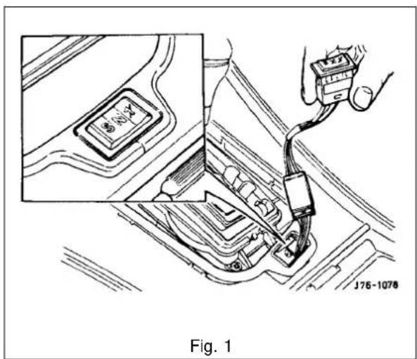


13.3.10 Radio Console, Renew
SRO 76.25.15
■ Remove the battery cover. Disconnect the battery.
■ Remove the console ashtray, see subsection 13.3.28.
■ Remove console veneer panel, see subsection 13.3.24.
■ Remove the gear selector ident plate securing screws.
- Carefully reposition the radio console assembly from the mounted position.
■ Disconnect the assembly harness multi-plugs.
■ Disconnect the antenna co-axial connector.
- Undo and remove the ground lead to radio securing nut.
■ Reposition the ground lead from radio stud.
■ Disconnect the radio harness multi-plugs.
■ Reposition the radio harness from the center console.
■ Displace the radio console assembly.
■ Remove the radio assembly from the console.
■ Remove the radio retaining plate.
- Undo and remove the air conditioning control module securing screws.
■ Displace and remove the module.
■ Undo and remove switch/clock module securing screws.
■ Displace and remove the module assembly.
■ Place the radio console aside.
■ Place the new radio console to the front.
■ Fit and fully seat the switch/clock module to the console.
■ Fit and tighten the module securing screws.
■ Fit and fully seat air conditioning module to the console.
■ Fit and tighten the securing screws.
■ Fit and fully seat the radio mounting plate to the console.
■ Place the radio console to the center console position.
■ Place the radio to the center console position.
- Route the radio harness / multi -plugs through the radio console into the center console position.
■ Connect the radio harness multi-plugs.
- Connect the radio console harness multi-plugs.
■ Route the radio ground and antenna leads through the radio console.
■ Fully seat the radio console inthe mounted position.
■ Fit and tighten the securing screws.
- Reposition the ground lead to radio securing stud.
■ Fitand tighten the securing nut.
■ Connect the antenna co-axial to the radio.
■ Reposition the excess harness / leads into the radio mounting hole, ensuring that the harnesses are positioned to allow the radio to be pushed fully home.
■ Fully seat the radio into the console.
■ Reposition and fit the selector ident plate.
■ Fit and tighten the ident plate securing screws.
■ Refit the console veneer panel.
■ Refit the console ashtray.
■ Reconnect the battery. Refit the battery cover.

13.3.11 Console Glove Box, Renew
SRO 76.25.16
■ Remove the console glove box lid, see subsection 13.3.12.
■ Undo and remove the glovebox/ ashtray securing screws.
■ Carefully displace the ashtray upwards for access.
■ Displace and remove the ashtraylid catch.
■ Displace and reposition the glove box assembly.
- Disconnect the security valet switch harness multi – plug.
■ Remove the glove box.
- Place the glove box to the front.
■ Displace and remove the valet switch.
■ Displace and remove the glove box lid checkarm.
- Displace and remove the glove box lid checkarm guide.
■ Place the glove box aside.
■ Place the new glove box to the front.
■ Fit and fully seat the checkarm guide to the glove box.
■ Fit and align the checkarm to the glove box.
■ Fit and fully seat the valet switch to the glove box.
■ Align and affix a security sticker to the glove box.
- Align and affix a cassette storage foam pad.
- Place the glove box assembly into position.
■ Reconnect the valet switch harness multi-plug.
■ Fit anfully seat the glove box assembly.
■ Fit and align the lid latch.
■ Reposition and fit the ashtray.
■ Fit and tighten the ashtray securing screws.
■ Refit the glove boxlid.


13.3.12 Console Glove Box Lid, Renew
SRO 76.25.18
- Open the console glove box lid.
■ Undo and remove the glove box lid checkarm to lid securing screw.
■ Reposition the checkarm. - Undo and remove the glove box lid to console securing screws.
- Displace and remove the glove box lid assembly.
- Place the lid assembly to the front.
- Undo and remove the lid inner securing screws.
- Displace and remove the lid inner.
- Displace and remove the lid latch release lever.
■ Undo and remove the lid hinge securing screw. - Displace and remove the hinge.
- Undo and remove the lid latch securing screw.
- Displace and remove the lid latch.
- Displace and remove the lid latch return spring.
- Place the lid aside.
- Place the new lid to the front.
- Fit and align the latch return spring to the lid.
- Fit and align the lid latch, ensuring that the latch leg locates behind the spring.
- Fit and tighten the latch securing screw.
- Fit and align the lid hinge.
- Fit and tighten the lid hinge securing screw.
- Fit and align the lid latch release lever.
- Fit and fully seat the lid inner to the lid.
- Fit and tighten the inner lid securing screws.
- Fit and align the lid assembly to the console.
- Fit and tighten the lid to console securing screws.
- Align the lid checkarm to the lid.
■ Fit and tighten the checkarm securing screw. - Close the glove box lid.
13.3.13 Console Glove Box Lid Hinge, Renew
SRO 76.25.20
■ Open the console glove box lid.
■ Undo and remove the glove box lid checkarm to lid securing screw.
■ Reposition the checkarm.
■ Undo and remove the glove box lid to console securing screws.
■ Displace and remove the glove boxlid assembly.
■ Place the lid assembly to the front.
■ Undo and remove the lid inner securing screws.
■ Displace and remove the lid inner.
■ Displace and remove the lid latch release lever.
■ Undo and remove the lid hinge securing screw.
■ Displace and remove the hinge.
■ Fit and align the new lid hinge.
■ Fit and tighten the lid hinge securing screw.
■ Fit and align the lid latch release lever.
■ Fit and fully seat the lid inner to the lid.
■ Fit and tighten the inner lid securing screws.
■ Fit and align the lid assembly to the console.
■ Fit and tighten the lid to console securing screws.
■ Align the lid checkarm to the lid.
■ Fit and tighten the checkarm securing screw.
■ Close the glove box lid.
13.3.14 Cupholder Trim Panel, Renew
SRO 76.25.21
■ Open the cupholder.
■ Undo and remove the cupholder trim panel securing screws.
- Displace and remove the trim panel assembly by releasing the lower edge and then displacing upwards.
- Carefully fit and fully seat the new trim panel.
■ Ensure the panel is correctly seated to the base.
■ Fit and tighten the trim panel securing screws.
■ Close the cupholder.


13.3.15 Cupholder, Renew
SRO 76.25.22
■ Remove the cupholder trim panel, see sub-section 13.3.14.
■ Displace and reposition the cupholder assembly from base (cupholder remains captive by spring).
■ Usinga suitable hook, disconnectthespringfromthe base and remove the cupholder.
■ Disconnect the return spring from the cupholder.
■ Place the cupholder aside.
■ Placethe new cupholder to the front.
■ Connect the return spring to the cupholder.
■ Place the cupholder into position.
■ Using a suitable hooktool, connect the return spring to the base.
■ Reposition and fit the cupholder assembly to the base.
■ Refit the cupholder trim panel.
13.3.16 Cupholder Latch, Renew
SRO 76.25.23
■ Remove the console glove box lid, see sub-section 13.3.12.
- Undo and remove the inner lid securing screws.
- Displace and remove the inner lid.
■ Open the cupholder.
■ Undo and remove the cupholder latch securing screw.
■ Displace and remove the latch assembly.
■ Fit and align the new latch assembly to the lid.
■ Fit and tighten the latch securing screw.
■ Fit and align the lid inner to the lid.
■ Fit and tighten the inner lid securing screws.
■ Close the cupholder.
■ Refit the the console glove box lid.

13.3.17 Fascia Board, Renew
SRO 76.46.01
■ Remove the battery cover and disconnect the battery.
- Removethe drivers side and passenger side underscuttle pads, see sub-sections 13.3.19 and 13.3.20.
■ Remove the drivers airbag module, see section 15.5.
■ Remove the steering wheel, section 10.
- Removethe drivers side and passenger side fascia closing panels, see sub-sections 13.3.22 and 13.3.21.
■ Remove the fascia center veneer panel, see subsection 13.3.23.
■ Remove the fascia board for access, see subsection 13.3.17.
- Disconnect the air conditioning differential potentiometer harness multi–plug.
■ Remove the differential potentiometer assembly.
- Displace and reposition the through panel connectors from the fascia assembly.
- Displace the fascia vent motor/ gearbox assemblies harness multi-plug from the mounting bracket.
- Disconnect and reposition the fascia harness to console harness multi–plug from the mounting bracket.
- Disconnect the BPU harness multi-plugs.
■ Removethe tiestraps securing the harness to the fascia.
■ Reposition the fascia on a bench.
- Displace and reposition the solar sensor assembly from the fascia.
- Disconnect the solar sensor harness multi-plug.
■ Remove the solar sensor assembly.
■ Undo and remove the defrost vents securing screws.
- Displace and reposition the defrost vent assemblies.
- Disconnect the tweeter speaker harness multi-plugs.
■ Remove the defrost vent assemblies.
■ Displace the fascia harness grommet from the fascia.
■ Route the harness through the aperture.
■ Remove the fascia harness assembly.
■ Undo and remove passenger airbag deployment door to fascia securing bolts (one bolt is removed with the fascia).
■ Displace and remove the deployment door assembly.
■ Undo and remove the passenger airbag module to fascia securing bolts.
■ Displace and remove the airbag module assembly.
■ Undo and remove the airbag module / BPU mounting bracket assembly to fascia securing nuts / bolts.
■ Displace and remove the mounting bracket assembly.
■ Retrieve the spacing washers.
■ Displace and remove the side vent outlets from the fascia.
■ Displace and remove the side vent ducts securing clips.
■ Displace and remove the side vent ducts.
■ Undo and remove the center vent flap assembly to fascia securing nuts.
■ Displace and remove the center vent flap assembly.
- Undo and remove fascia location bracket securing nuts.
- Displace and remove the location bracket.


■ Undo and remove the defrost vents clip location bracket securing screws.
- Displace and remove the clip location brackets.
- Remove the defrost vent spire clips from the fascia.
■ Place the fascia aside.
■ Place a new fascia on the bench.
■ Fit and fully seat the defrost vent spire clips.
■ Fit and align the defrost vent clip location brackets.
■ Fit and tighten the location brackets securing screws.
■ Fit and align the fascia location brackets to the fascia.
■ Fit and align the location bracket securing nuts.
■ Fit and align the center vent flap assembly.
■ Fit and tighten the flap assembly securing nuts.
■ Fit and align the side vent ducts to the fascia assembly.
■ Fit anfully seat the side vent ducts securing clips.
■ Fit and fully seat the side vent outlets to the fascia.
- Fit and align the airbag module / BPU mounting bracket assembly and align the spacers.
■ Fit and tighten the airbag module/ BPU mounting bracket securing nuts/ bolts.
■ Fit and align the airbag module to the fascia.
■ Fit and tighten the airbag module securing bolts.
■ Fit and align the airbag deployment door assembly to the fascia.
- Put do notfully tighten the door securing bolts.
■ Align the door assembly to the fascia.
■ Finally tighten the door securing bolts.
- Position the harness. Route the harness speaker / solar sensor multi-plugs through the aperture in the fascia.
■ Fully seat the harness grommet to the fascia aperture.
- Route the tweeter speaker harnesses along the defrost vent aperture.
- Place the defrost vent assemblies to the fascia.
- Connect the speaker harness multi-plugs to the speakers.
■ Reposition and fit the vent assemblies to the fascia.
■ Fit and tighten the vent securing screws.
- Place the solar sensor assembly to the fascia.
■ Reconnect the solar sensor harness multi-plug.
■ Fully seat the solar sensor assembly to the fascia.
■ Reposition the fascia assembly on the bench.
- Secure the harness to the fascia assembly using tiestraps.
■ Reconnect the BPU harness multi-plugs.
■ Reposition and the fascia harness to console harness multi-plug to the mounting bracket.
■ Reconnect the fascia vent motor/gearbox assemblies harness multi-plug.

- Reposition and the motor/gearbox assemblies harness multi-plug to the mounting bracket.
■ Fully seat the through panel connectors to the fascia. - Place the air conditioning differential potentiometer to the fascia and route the differential potentiometer harness through the vent aperture.
■ Reconnect the differential potentiometer harness multi- plug. - Refit the fascia board.
■ Refit the center veneer panel.
■ Refit the fascia closing panels.
■ Refit the steering wheel.
■ Refit the drivers airbag module.
■ Refit the underscuttle pads.
■ Reconnect the battery and refit the battery cover.


13.3.18 Fascia Board - Remove For Access And Refit
SRO 76.46.01/90
■ Remove the battery cover. Disconnect the battery.
- Remove the drivers side and passenger side underscuttle pads, see sub-sections 13.3.19 and 13.3.20.
■ Remove the drivers airbag module, see section 15.5.
■ Remove the steering wheel, section 10.
- Removethe drivers side fascia closing panel, see sub-section 13.3.22.
■ Remove the passenger side fascia closing panel, see sub-section 13.3.21.
■ Remove the fascia center veneer panel, see subsection 13.2.23.
■ Undo and remove the fascia tie bar securing nuts.
■ Displace the tie bars.
■ Undo and remove the instrument housing/fascia switch-pack securing screws.
■ Reposition the multi–plug mounting bracket.
- Disconnect the steering column control module multi-plugs.
- Disconnect the fascia switchpack harness multi-plugs.
■ Displace and reposition the instrument pack for access.
■ Disconnect the instrument pack harness multi-plugs.
■ Remove the instrument pack / fascia switchpack assembly.
- Disconnect the right hand fascia harness to cabin harness multi -plug.
- Disconnect the column switchgear and column motors harness multi-plug.
- Disconnect the ignition switch harness multi-plug.
■ Disconnect the exciter coil harness multi-plug.
- Disconnect the speaker tweeter harness multi -plug.
- Disconnect the speed control control module harness multi-plug.
■ Undo and remove the fascia to center console securing screws.
■ Displace and remove the passenger side outlet duct.
- Disconnect the fascia harness to console harness multi-plugs.
- Disconnect the let3 hand fascia harness to cabin harness multi-plug.
■ Undo and remove the fascia ground eyelets to body securing nut.
■ Displace and reposition the ground eyelets from the stud.
■ Displace and reposition the airbag control module from the mounting bracket.
■ Undo and remove the fascia assembly lower securing nut.
■ Undo and remove the fascia outer body bracket to fascia securing bolts.
- Carefully displace the fascia rearwards.

- From behind the fascia passenger side, disconnect the passenger airbag harness multi-plug.
■ With assistance, remove the fascia from the vehicle and place on a suitably protected bench.
- Place the fascia in position in the vehicle with the center location peg correctly engaged.
- Reconnect the passenger airbag module harness multi-plug.
■ Carefully fit and align the fascia to the mounting position.
■ Fit and tighten the fascia to outer body brackets securing bolts.
■ Fit and tighten the fascia assembly lower securing nut.
- Reposition and fit the airbag control module to the mounting bracket.
■ Reposition and fit the fascia harness ground eyelets to the ground stud.
■ Fit and tighten the ground eyelet securing nut.
■ Reconnect the left hand fascia harness to cabin housing harness multi-plug.
■ Reconnect the fascia harness to console harness multi-plugs.
■ Fit and align the passenger side outlet duct.
■ Fit and tighten the fascia to console securing screws.
■ Reconnect the speed control harness multi-plug.
■ Reconnect the speaker tweeter harness multi- plug.
■ Reconnect the exciter coil harness multi-plug.
- Reconnect the column switchgear and column motor harness multi-plugs.
■ Reconnect the right hand fascia harness to cabin harness multi -plug.
■ Place the instrument pack /fascia switchpack in position.
■ Reconnect the instrument pack harness multi- plugs.
■ Reposition and fit the instrumentpack assembly to the fascia.
- Reconnect the fascia switchpack harness multi-plugs.
- Reconnect the steering column harness multi –plugs.
■ Reposition and the switchpack harness multi-plug mounting bracket.
■ Fit and tighten the instrument pack/ switchpack securing bolts.
■ Fit and align the fascia tie bars.
■ Fit and tighten the tie bar securing nuts.
■ Refit the center veneer panel.
- Refit the fascia closing panels.
■ Refit the steering wheel.
■ Refit the drivers airbag module.
■ Refit the underscuttle pads.
■ Reconnect the battery and refit the battery covers.


13.3.19 Underscuttle Pad - Drivers Side, Remove For Access And Refit
SRO 76.46.11/90
■ Motor the drivers seat fully rearwards.
■ Undo and remove the underscuttle pad securing screws (1 Fig. 1).
■ Using special tool JD188(2 Fig. 1), displace securing clip.
- Displace and reposition the underscuttle pad assembly (3 Fig 1).
■ Disconnect the air conditioning aspirator multi-plug.
■ Remove the underscuttle pad.
■ Place the underscuttle pad assembly in position.
■ Connect the air conditioning aspirator multi-plug.
■ Reposition the underscuttle pad.
- Secure the underscuttle pad with clip and align the securing screw holes.
■ Fit and tighten the underscuttle pad securing screws.
■ Motor the seat to the original position.
13.3.20 Underscuttle Pad - Passenger Side, Remove For Access And Refit
SRO 76.46.15/90
■ Motor the passenger seatfully rearwards.
■ Undo and remove the underscuttle pad securing screws.
■ Using special tool JD 188, displace the securing clip.
- Displace and remove the underscuttle pad.
- Place the underscuttle pad assembly in position.
- Secure the underscuttle pad with clip and align the securing screw holes.
- Fit and tighten the underscuttle pad securing screws.
■ Motor the seat to the original position.

13.3.21 Fascia Closing Panel - Passenger Side, Renew
SRO 76.46.27
- Remove for access the passenger side underscuttle pad, see sub-section 13.3.20.
■ Undo and remove the closing panel to fascia support bracket fir-tree fixing (Fig.1).
■ Displace and remove the closing panel.
■ Remove the draught welt.
■ Place the panel to the front.
■ Displace and remove the end panel securing clip.
■ Place new closing panel to the front.
■ Fit anfully seat the end panel securing clip.
■ Fit and fully seat the end panel to the vehicle.
■ Fit and tighten the end panel to fascia support bracket clip.
■ Refit the underscuttle pad.
13.3.22 Fascia Closing Panel - Drivers Side, Renew
SRO 76.46.28
- Remove for access the drivers side underscuttle pad, see sub-section 13.2.19.
■ Undo and remove the closing panel to fascia support bracket securing nut (Fig.1).
■ Displace and remove the closing panel. - Place the panel to the front.
■ Displace and remove the end panel securing clip. - Place new closing panel to the front.
- Fit and fully seat the end panel securing clip.
• Fit and fully seat the end panel to the vehicle. - Fit and tighten the end panel to fascia support bracket securing nut.
■ Refit the underscuttle pad.

13.3.23 fasciaCenter Veneer Panel, Renew
SRO 76.47.06
■ Fit and align the special tool JD 202 to the center vent assembly. See Fig. 1.
■ Displace and reposition the center vent assembly.
■ Remove the special tool from the vent.
■ Displace and remove the center vent assembly from the variable differential control potentiometer.
■ Place the center vent assembly on a bench covered with a suitable cloth.
■ Remove and discard the veneer panel to center vent assembly securing clips.
■ Displace and remove the veneer panel from the center vent.
- Fit and align the new veneer panel to the center vent.
■ Fit and fully seat the veneer panel securing clips.
■ Place the center vent assembly to the vehicle.
- Fit and fully seat the vent assembly to differential control potentiometer.
■ Fit and fully seat the center vent assembly to the fascia.

13.3.24 Console Finisher Veneer Panel, Renew
SRO 76.47.26
■ Apply the handbrake.
■ Turn the ignition.
■ Press the brake pedal and position the gear selector in 'N'.
■ Turn the ignition OFF.
■ Remove the console ashtray, see sub-section 13.3.28.
- Carefully displace the mode switch from the gear surround finisher. See Fig. 1.
■ Disconnect the mode switch from the harness multi-plug. See Fig. 1.
■ Displace and remove the switch surround finisher.
■ Displace and remove the gear lever surround finisher.
■ Displace and remove the veneer panel rear finisher.
■ Undo and remove the veneer panel wing nuts. See Fig. 2.
■ Displace and remove the console finisher veneer panel. See Fig. 3.
■ Remove the stud plates.
■ Place the veneer panel aside.
■ Place the new panel to the front.
■ Fit and align the stud plates.
■ Fit and fully seat the veneer panel to the console.
■ Fully seat the rear of the veneer panel.
■ Fit and tighten thewing nuts.
■ Fit and align the veneer panel rear finisher.
■ Fit and fully seat the gear lever surround.
■ Fit and fully seat the mode switch surround.
■ Connect the mode switch to harness multi-plug.
■ Fully seat the mode switch.
■ Refit the ashtray.
■ Place the gear selector in 'P'.

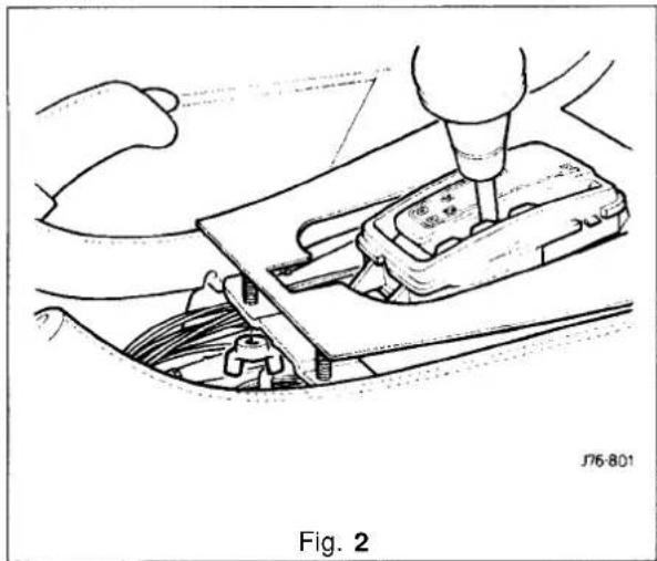


13.3.25 Console Ashtray Lid Veneer Panel, Renew
SRO 76.47.27
■ Remove the console ashtray, see subsection 13.3.28 and Fig 1.
■ Open the ashtraid.
- Displace and remove the veneer panel securing spire clips.
■ Displace and remove the veneer panel.
■ Fit and seat the new veneer panel to ashtray lid,
■ Fit the veneer panel securing spire clips.
- Close the ashtray.
■ Refit the ashtray.
13.3.26 Console Ashtray Surround Veneer Panel, Renew
SRO 76.47.28
■ Remove the console ashtray, see sub-section 13.3.28 and Fig. 1.
■ Displace and remove the surround veneer panel securing spire clips.
■ Open the ashtray.
- Displace and remove the veneer panel from the ashtray.
■ Fit and seat the new veneer panel to the ashtray
■ Secure the veneer panel with spire clips.
■ Close the ashtray.
13.3.27 Console Rear Extension Veneer Panel, Renew
SRO 76.47.30
■ Remove the console rear extension finisher, see sub-section 13.3.5 and Fig. 2.
■ Reposition the front of the veneer panel upwards for access and displace the rear of the panel upwards to release.
■ Fit and seat the new veneer panel to the extension and ensure that the rear pegs are fully seated.
■Refit the trim finisher.
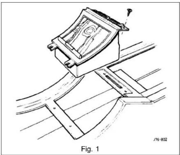


13.3.28 Console Ashtray, Renew
SRO 76.67.18
■ Raise the trunk.
■ Remove the battery cover and disconnect the battery.
■ Open the glove bid.
■ Undo and remove the ashtray assembly securing screws.
■ Displace the ashtray for access.
■ Disconnect cigar lighter/illumination Lucar connectors.
■ Displace and remove the ashtray assembly.
■ Place the ashtray assembly to the front.
■ Open the ashtraiyol.
- Displace and remove the inner ashtray.
■ Displace and remove the cigar lighter element assembly. - Carefully displace and remove the cigar lighter illumination bulb holder assembly.
- Carefully displace and remove the cigar lighter assembly from the ashtray.
■ Carefully remove and discard the ashtray surround veneer panel securing clips.
- Displace and remove the ashtray surround veneer panel. - Carefully remove and discard the ashtray lid veneer panel securing clips.
■ Close the ashtray.
■Displace and remove the ashtraylid veneer panel.
- Displace and remove the inner ashtray retaining clips.
■ Place the ashtray aside.
■ Place the new ashtray to the front.
■ Fit anfully seat the inner ashtray retaining clips.
■ Fit and align the lid veneer panel.
■ Fit anfully seat the veneer panel securing clips.
■ Open the ashtray lid.
■ Fit and align the ashtray surround veneer panel.
■ Fit and fully seat the veneer panel securing clips.
■ Fit anfully seat the cigar lighter assembly.
- Fit andfully seat the illumination bulb assembly, ensuring that the ground tag contacts the cigar lighter body.
■ Fit the cigar lighter element assembly.
■ Fit the inner ashtray and close the ashtray lid.
■ Place the ashtrain position.
■ Reconnect the Lucar connectors.
■ Reposition and the ashtray assembly.
■ Fit and tighten the ashtray securing screws.
■ Close the glovebox lid.
■ Reconnect the battery and refit the battery cover.


13.3.29 Steering Column Upper Cowl, Renew
SRO 76.46.02
■ Motor the drivers seat fully rearward.
- Undo and remove the lower cowl fixing screws (1 Fig. 1).
■ Displace and reposition the lower cowl (2 Fig. 1); discard the ignition lock rubber gaiter (3 Fig. 1).
■ Motor the steering column fully upwards.
■ Undo and remove the upper column securing screws.
■ Motor the column fully downwards.
- Displace and remove the upper cowl (4 Fig. 1).
• Fit and align the new cowl into position.
■ Motor the column fully upwards.
■ Fit and tighten the cowl securing screws.
- Fit a new ignition lock rubber gaiter and position the lower cowl to the steering column.
■ Fit and tighten the cowl securing screws.
■ Motor the column to the original position.
13.3.30 Steering Column Lower Cowl, Renew
SRO 76.46.03
■ Motor the drivers seat fully rearwards.
■ Undo and remove the lower column cowl securing screws (1 Fig. 1).
■ Displace and reposition the lower cowl(2 Fig. 1).
■ Disconnect the rheostat multi-plug (5 Fig. 1).
- Disconnect the tilt column harness multi - plug from the tilt column switch (6Fig. 1).
■ Remove the cowl and placeto the front; remove the ignition lock rubber gaiter and discard (3 Fig. 1).
■ Displace and remove the rheostat adjusting knob (7 Fig. 1).
■ Undo and remove the rheostat securing screws(8 Fig.1).
- Displace the tilt column switch retaining tangs and remove the switch.
■ Place the cowl aside.
■ Place the new lower cowl to the front.
■ Fit and fully seat the column switch.
■ Fit and align the rheostat. Fit and tighten the rheostat securing screws.
■ Fit and fully seat the rheostat knob.
- Fit new ignition switch rubber gaiter and reposition the lower cowl.
■ Connect the rheostat harness multi -plug.
■ Connect the column switch harness multi-plug.
■ Position the cowl to the steering column.
■ Fit and tighten the cowl securing screws.
■ Motor the seat to the original position.
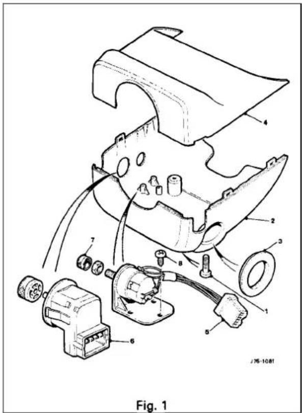
13.3.31 Steering Column Switchgear Mounting Bracket, Renew
SRO 76.46.33
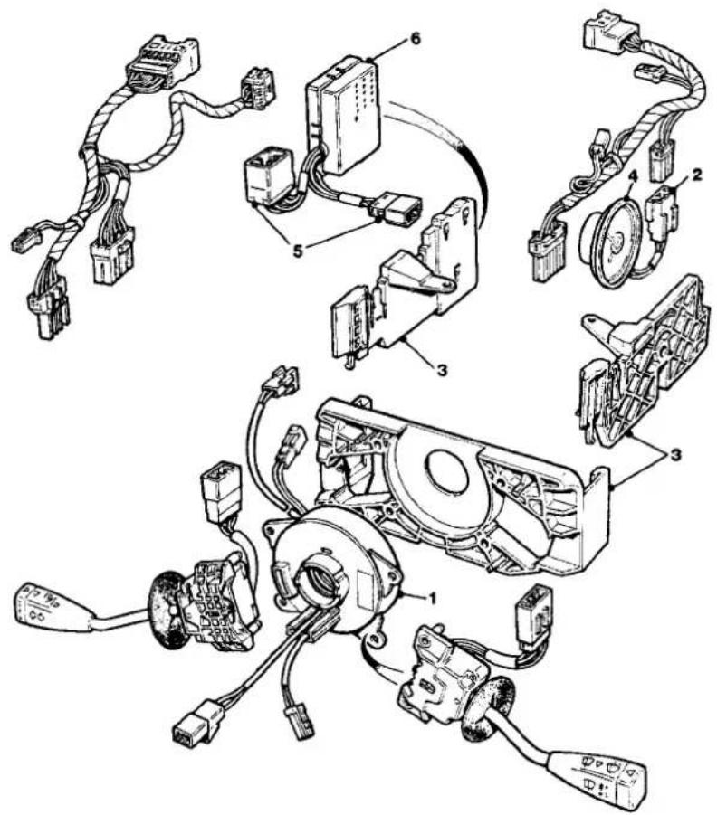
J76-1082
Fig. 1
- Remove the steering column lower and upper cowls, see subsections 13.3.30 and 13.3.29.
■ Remove the battery cover and disconnect the battery.
■ Remove the driver airbag module, see section 15.1.
■ Remove the steering wheel, see section 10.
■ Remove the cassette and cancellation module (1 Fig. 1), see section 10. - Displace the audible warning speaker multi–plug (2 Fig. 1) from the mounting bracket(3Fig. 1).
■ Disconnect the speaker multi-plug. - Displace and remove the switch gear mounting bracket(3 Fig. 1).
■ Undo and remove the audible warning speaker securing screws.
■ Undo and remove speaker/ harness securing'P' clip nut.
■ Displace the 'P' clip nut.
■ Remove the audible warning speaker (4 Fig. 1). - Displacethedimmer modulemulti-plug (5 Fig. 1) from the mounting bracket.


Fig. 1
■ Displace and remove the dimmer module (6 Fig. 1).
■ Discard the foam pads from the mounting bracket.
■ Place the mounting bracket aside.
- Place new mounting bracket to the front.
■ Place new foam pads to the front.
■ Remove the foam backing paper.
■ Fit and fully seat the pads to the mounting bracket.
■ Fit and align the audible warning speakertothe mounting bracket.
■ Fit and tighten the speaker securing screws.
- Fit and align the speaker harness 'P' clip.
■ Fit and tighten the clip securingnut.
■ Fit and align the switchgear mounting bracket.
■ Connect the speaker harness multi-plug.
■ Position the harness to the mounting bracket.
■ Refit the cassette and cancellation module.
■ Refit the steering wheel.
■ Refit the driver airbag.
■ Reconnect the battery and refit the battery cover.
■ Close the trunk.
■ Refit the steering column upper and lower cowls.
13.3.32 'A' Post lower Trim Pad, Renew
SRO 76.13.30
■ Locally displace the draught welting from the front door aperture flange.
■ Undo and remove the'A' post lower trim pad quarter turn fastener.
- Displace and remove theA' post lower trim pad by pulling rearwards to disengage clips and place aside.
■ Fit and seat the new'A' post lower trim pad, engaging the clips on the front door flange.
- Fit and secure the 'A' post lower trim pad quarter turn fastener.
- Reposition and fully seat the draught welting to the front door aperture flange.
13.3.33 Rear Quarter Upper Trim Pad, Renew
■ Remove the rear seat belt upper anchorage RH or LH.
■ Remove the trim pad securing screw.
■ Slacken but do not remove the combined grab handle and coat hook securing screws.
■ Unclip the rear quarter trim pad and remove.
■ To refit, carry out reversal of the above procedure, noting that seat belt fixings must be tightened to the specified torque.
13.3.34 'B' Post Upper Trim Pad, Renew
■ Position front seat and squab fully forward.
■ Remove seat belt lower anchorage and feed the belt through the lower trim aperture.
■ Remove seat belt upper anchorage.
■ Remove trim finisher upper seat belt aperture and door aperture edge trim.
■ Release upper trim pad from its fixings by exerting downward pressure.
■ To refit, carry out reversal of the above procedure.
WARNING: ENSURE THAT THE SEAT BELT IS CORRECTLY ASSEMBLED AND FIXINGS TORQUE TIGH-TENED.
13.3.35 'B' Post lower Trim Pad, Renew
■ Position front seat and squab fully forward.
- Remove seat belt lower anchorage and feed the belt through the lower trim aperture.
■ Release trim pad quarter turn fasteners and remove trim pad.
- Remove fasteners from trim pad as required.
■ To refit, carry out reversal of the above procedure.
WARNING: ENSURE THAT THE SEAT BELT IS CORRECTLY ASSEMBLED AND FIXINGS TORQUE TIGH-TENED.


13.3.36 Handbrake Lever Trim, Renew
- Release the trim assembly upper clip and remove trim from handbrake lever.
- To refit, carry out reversal of the above procedure.
13.3.37 Combined Grab Handle and Coat Hanger Hook, Renew
- Carefully prise out and remove screw cover.
■ Remove screws and handle / coat hook.
■ To refit, carry out reversal of the above procedure.
13.3.38 Sun Visor Assembly RH or LH, Renew
- Disconnect vehicle battery ground lead.
■ Lower the sunvisor. - Remove the screws securing the sunvisor retaining block and support the sunvisor.
- Disconnect the multi-plug situated behind the headlining and remove the sunvisor assembly.
- To refit, carry out reversal of the above procedure.
13.3.39 Roof lining (Headlining), Description
The roof lining is a one piece construction of 6mm thick polyurethane foam, covered with brush finish, suede effect, knitted polyester.
13.3.40 Roof Lining, Renew
■ Positionfront seats fully rearwards and recline the passenger seat squab.
■ Disconnect vehicle battery ground lead.
■ Remove:
- Sliding roof flange (where fitted).
- Front passenger door.
- Rear console (where fitted).
- Center console.
Sunblind and bezel.
○ Combined grab handle and coat hook. - Rear quarter upper trim pad LH& RH.
- Cantrail crash roll.
- Illuminated sun visor.
-
Roof console.
-
Release multi -plug connectors from clips at roof console aperture.
■ Remove roof console retaining clip from headlining. - Remove security sensors (where fitted) and disconnect multi-plugs.
■ Release roof lining to body tags and lower roof lining.
■ Remove the roof lining:
■ Position the roof lining with the rear corner through the passenger side rear door and the opposite corner through the driver side rear door.
■ Position the roof lining across the car with the roof console cut-out straddling 'B'–'C' post. - Tip the roof lining forward against bottom of fascia with rear edge of roof lining diagonally across door aperture.
- Carefully feed the roof lining out of the passenger side front door, easing the edge cut-outs over the door aperture and any other obstruction.
■ To refit, carry out reversal of the above procedure.


13.4 TRUNK
13.4.1 Trunk, Description
The trunk houses the spare wheel, the battery, an electrical carrier containing electrical fuses, relays and modules and a compact disc auto-changer attached to body bracketry. The trunk is fitted with push-fit, velour finish, liners (1 Fig. 1) to the sides and front inner panel; the trunk floor is covered with carpet attached to a removable floor board (2 Fig. 1) and a battery cover (3 Fig. 1), one covering the spare wheel and wheel changing equipment, the other covering the battery and electrical carrier.
The floor board rests on the spare wheel, the front and rear edges of the floor board locating blocks on the fuel tank backboard and on the rear of the body. The blocks accommodate the two possible height settings caused by the difference in thickness between the space saver and full sized spare wheels.
A tread plate (4 Fig. 1) is attached to the trunk sill and a liner is fitted to the rear of the trunk below the sill. Interior trim finisher panels are fitted to the rear lamp units accessed from the trunk opening.
The trunk lid(5 Fig. 1) is fitted with a removable moulded liner and two trunk illumination lights; the lid is supported by two gas struts, attached through pressn fittings between the inner wheel arch and trunk hinge (6Fig. 1). A warning triangle is attached by a bracket to the trunk lid and retained inthe open position by a rubber block (Europe inc UK only).
Trunk locking is based on a central latch and striker, operated electrically through the central locking system by an adjacent actuator or by key in a barrel lock located behind the trunk lid badge.
For details on renewal of trunk front and side liners, trunk carpet, trunk seal retainer and battery cover, see relevant Service Repair Operations.
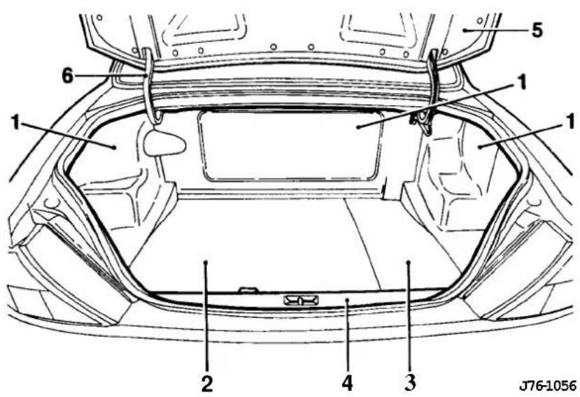
- Trunk Liners
- Removable floor board
-
Battery cover
-
Treadplate
- Trunk lid
- Hinge
Fig. 1 Trunk Components and Trim

13.4.2 Trunk Side Liner - Left Hand, Renew
SRO 76.19.22
- Raise trunk lid.
■ Remove the trunk floor carpet (1 Fig. 1), see subsection 13.4.4.
■ Remove the trunk front liner (2 Fig. 1), see subsection 13.4.5.
■ Remove the trunk seal retainer(5Fig. 1), see subsection 13.4.6.
■ Displace and remove the trunkside liner (3Fig. 1), passing the fuel filler manual release cable through the liner. - Fit and align the new trunk side liner, passing the fuel filler manual release cable through the liner.
■ Refit the trunk seal retainer.
■ Refit theunk front liner.
■ Refit the trunk floor carpet.

13.4.3 Trunk Side liner - Right Hand, Renew
SRO 76.19.23
- Raise the trunk lid.
■ Remove the trunk floor carpet Fig. 1), see subsection 13.4.4.
■ Remove the trunk front liner (2 Fig. 1), see subsection 13.4.5.
■ Remove the trunk seal retainer (5 Fig. 1), see subsection 13.4.6.
■Displace and remove the literature pack from the trunk side liner.
■ Displace and remove the trunk side line(4Fig. 1).
■ Fit and align new side liner.
■ Fit and align the literature pack to the trunk side liner.
■ Refit the trunk seal retainer.
■ Refit the trunk front liner.
■ Refit the trunk floor carpet.
13.4.4 Trunk Floor Carpet, Renew
SRO 76.19.30
- Displace and remove the trunk floor carpet assembly.
■ Fit, align and seat new trunk floor carpet assembly.
13.4.5 Trunk Front Liner, Renew
SRO 76.19.31
■ Remove the battery cover.
■ Remove the trunk floor carpet, see subsection 13.4.4.
■ Displace and remove the trunk floor liner.
■ Fit, align and seat new trunk front liner.
■ Refit the trunk floor carpet.
■ Refit the battery cover.


■ Remove the trunk floor carpet, see sub-section 13.4.4.
■ Displace and remove the left and right hand tail light covers.
■ Undo and remove the trunk seal retainer securing bolts (arrowed on Fig. 1).
■ Displace and remove the trunk seal retainer.
■ Fit and fully seat the new trunk seal retainer.
■ Fit and fully tighten the trunkseal retainer securing bolts.
■ Fit and fully seat the tail light covers.
■ Refit the trunk floor carpet.
13.4.7 Trunk Lid Striker, Adjust
■ Disconnect vehicle battery ground lead.
■ Remove the rear finisher.
■ Slacken the striker plate securing bolts and adjust the striker to ensure that the luggage compartment lid aligns


13.4.12 Trunk Lid Lock Mechanism, Renew
■ Open the trunk and remove the mechanism cover.
■ Disconnect the operating rod from the remote linkage.
- Removethetwo lock assembly securing bolts, remove the lock from the trunk. lid and remove the assembly from the vehicle.
■ To refit, carry out reversal of the above procedure.
13.4.13 Trunk Lid Gas Strut, Adjust, Renew
- Open the trunk.
- Insert a screwdriver and remove the strut from the top pivot and repeat the operation for the lower pivot.
- Fit the strut to the lower pivot first to aid re-assembly.
■ To refit, carry out reversal of the above procedure, changing one strut at a time.
13.4.14 Trunk Lid Hinge, Renew
■ Open the trunk.
■ Remove the hinge cover.
- Cut and remove the harness straps from the RH hinge and move the harness away.
Note: Ensure that the lid is adequately supported and that paint damage cannot occur.
■ Remove the upper hinge securing bolts.
■ Remove the lower hinge fixings.
■ To refit, carry out reversal of the above procedure, ensuring that the alignment of the trunk buffers is set relative to the fenders.
13.4.15 Trunk Rear Liner, Renew
■ Disconnect vehicle battery ground lead.
- Peel back the floor carpet and sound insulation for access.
■ Remove the tread plate.
■ Remove the trunk rear liner.
■ To refit, carry out reversal of the above procedure.


13.5 HOOD
13.5.1 Hood, Description
The hood is fitted with black moulded covers over the inner fenders and behind the headlamp units; the right hand fender cover incorporates compartments for spare fuses and tool kit (where fitted). Two gas struts attached by press-on fittings on the body and hood support the hood cover.
13.5.2 Plenum Chamber Finisher, Renew
SRO 76.10.01
- Open the hood and fit suitable fender cover.
■ Remove the wiper arm, see section 15.6.
■ Undo and remove the plenum chamber finisher securing screws (1 Fig. 1).
■ Displace and reposition the plenum chamber.
■ Disconnect the washer jet tubes.
■ Disconnect the washer jet multi-plugs.
■ Displace the washer jet securing tangs.
■ Displace and remove the washer jets(2 Fig. 1).
■ Place the finisher aside.
■Fit and fully seat the washer jets to the new plenum chamber finisher.
■Connect the washer jet multi-plugs.
■ Reconnect the washer jet tubes.
■ Position the plenum chamber finisher.
■Fit and tighten the finisher securing screws.
■Refit the wiper arm.
■ Remove the fender cover and close the hood.

13.5.3 Hinge, Renew
■ Disconnect vehicle battery ground lead.
■ Open hood and fit fender protectors.
■ Remove radiator grille.
■ 12 cylinder only:
■ Remove fan cowl to top panel clips and move the cowl assembly clear.
■ Move water bleed pipe from top panel clips.
■ Release fixings and remove radiator top mounting panel.
■ Remove hinge securing nutsRH or LH (ground lead on the left hand side).
CAUTION: Ensure that the hood cover is adequately supported and that paint damage cannot occur.
■ Remove hinge bolts RH or LH, noting the position of the ground lead on the left hand side.
■ To refit, carry out reversal of the above procedure, ensuring that the hood should be fully aligned before finally torque tightening the fixings.

13.5.4 Gas StruRenew
■ Disconnect vehicle battery ground lead.
■ Open the hood and fit fender protectors.
CAUTION: Ensure that the hood cover is adequately supported and that paint damage cannot occur.
■ Release upper strut pivot retaining clip and detach the strut from the pivot.
■ Repeat for the lower pivot and remove the gas strut.
• To refit, carry out reversal of the above procedure.
13.5.5 Hood Lock RH or LH, Renew
- Open the hood and disconnect the lock operating cable from the lock.
■ Remove the bolts securing the lock to the body and remove the lock.
■ To refit, carry out reversal of the above procedure. Align the lockwith the striker prior to tightening.

13.5.6 Hood Lock Control Cable RH or LH, Renew
■ Slackenthe clamp bolt securing thecabletothe lock actuator.
- Disconnect the cable from the lock and from the mounting clip.
- Release the cable from the bulkhead mounting clips and remove the tie wraps securing the cable to the pipes and harnesses.
■ Remove the cable from the remaining large tie wraps.
■ Open the front door.
■ Remove the underscuttle pad.
■ Pull the release handle and disconnect the cable from the release handle and bracket.
- Pull the cable through the bulkhead grommet and discard.
- To refit, carry out reversal of the above procedure.
13.5.7 Hood Striker Assembly, Renew
■ Open the hood, slacken the locknut and unscrew the striker.
■ Renew any damaged components and reassemble.
- A distance of 62mm from the end of the striker to the locknut may be used as an initial setting.
- Adjust the striker until the hood is flush with the fender.
13.5.8 Hood Lock Release Handle, Renew
■With the hood raised: slacken the clamp bolt which secures the cable to the lock actuator. Repeat the procedure for the other side.
- Open the driver side door.
■ Remove the underscuttle pad.
■ Disconnect the inner cables from the hood release handle.
■ Remove the bolts securing the hood release handle to the body, remove the cables from the handle and remove from the vehicle.
- To refit, carry out reversal of the above procedure.

13.6 GLAZING (FIXED)
13.6.1 Glazing (Fixed), Description
The fixed glazing comprises internal and external driving mirrors, sunvisor mirror and rear quarter light glass; see Appendix A4, Body Components and Trim for details of the windscreen and rear screen glazing.
13.6.2 Interior Mirror, Renew
■ Disconnect vehicle battery ground lead.
- Rotate mirror stem approximately one quarter turn clockwise to release stem from spring contact on windscreen boss.
■ Disconnect mirror harness.
- To refit, locate mirror stem base on windscreen boss with stem parallel to top of windscreen, ie one quarter turn displaced from normal position; apply firmly over boss and turn anticlockwise to lock stem on windscreen boss.
■ Reconnect mirror harness.
13.6.3 Sun Visor Mirror Assembly, Renew
■ Disconnect vehicle battery ground lead.
■ Lower the sunvisor.
■ Raise the sunvisor cover and remove the lenses.
- Remove the screws securing the mirror to the sunvisor and remove the mirror.
- To refit, carry out reversal of the above procedure, taking care to correctly locate switch and bulb holders prior to securing the mirror.
13.6.4 Exterior Mirror, Renew
■ Disconnect vehicle battery ground lead.
- Remove door trim pad veneer panel and upper trim pad.
■ Remove the cheater by slidingoff.
■ Remove mirror fixings.
■ Disconnect the mirror harness block connectors.
■ Remove the mirror securing screws and remove the mirror assembly.
■ To refit, carry out reversal of the above procedure.
13.6.5 Exterior Mirror Glass, Renew
■ Switch ignition on and position the mirror to inboard position.
■ Disconnect vehicle battery ground lead.
■ Slide assembly outboard and pull outwards.
■ To refit, carry out reversal of the above procedure.
13.7 CARPETS
13.7.1 Carpets, Description
The passenger compartment carpet is a one piece moulded construction with integrated sound deadening, heel mats and driver's footrest. The carpet is attached to the vehicle floor by plastic clips fitted below the door treadplates. Removal of the carpet requires removal of front seats and the lifting the rear console and removal of the heelboard carpet.
13.7.2 Removal of Stains - General Information
When carrying out any stain removal procedures, observe the following points:
- Immediate action is essential if permanent staining is to be avoided.
- Endeavour to clarify stain, ie water, oil, or combinations and treat accordingly.
○ Always work from the edge to the centre of the stain to prevent spreading.
Do not rub or agitate too vigorously as this action could distort or damage the pile.
Do not over-wet the carpet.
Do not over-apply cleaning solvent to foam-backed carpets as this could cause damage to the latex backing compounds.
When using more than one treatment on the same stain, allow adequate drying time between applications.
To remove excess moisture, cover the affected area with dry, undyed cloths, white paper towels, etc and weight down; moisture removal is then effected by capillary action.
13.7.3 Powder Cleaning – Removal of Small Spillage Stains
Note: Powder cleaners are absorbent particles carrying a solvent / detergent liquor; this type of cleaner is suitable for quick, effective cleaning of all the carpet or of small areas without using chemicals. As the carpet is never more than damp, no drying time is necessary on completion of the cleaning cycle.
To clean carpets using powder cleaners:
○ Brush powder onto carpet, allow to dry for 30 minutes and follow the cleaner manufacturers instructions.
- Remove powder and stain by normal vacuum cleaner action.


13.7.4 Spot Cleaning-Localized Stains
Localized stains caused by accidental spillage may be one of three types:
Water based stains caused by foodstuffs, starches, sugars, soft drinks, fruit stains, washable ink etc. These stains adhere readily to the pile and do not respond to vacuum cleaning. They are best removed immediately using the procedure detailed below.
Oil/grease based stains caused by spillage or other contamination by butter, grease, hand cream, ball point pen ink, crayon, lipstick etc.
○ A combination of both these types.
To remove water based stains:
■ Blot up liquids and/or scrape off semi-solids using a spatula.
- Sponge the affected area with clean luke-warm water. Use a clean, damp, undyed, cotton cloth to absorb as much of the moisture as possible, working from the edge to the centre of the stain.
- If the stain persists, apply a suitable carpet shampoo solution made up to the manufacturers instructions, again working from the edge to the centre of the stain.
- Rinse with clean, warm water, taking care not to over-wet the carpet.
- Absorb excess moisture by laying dry, undyed cloths or white paper towels over the moist carpet under light pressure; replace when necessary.
- When the carpet is thoroughly dry, vacuum clean the area to lift the carpet pile.
CAUTION: When liquids are applied to the pile, use only a clean cloth or sponge. Do not apply liquids directly to the carpet- when attempting to removestains, blot the pile as heavy rubbing can destroy the yarn structure of the carpet.
To remove oil /grease based stains:
■ Using a suitable aerosol containing solvent loaded with absorbent powder, spray the affected areas of the carpet. The solvent loosens the grease from the fibre and the powder then absorbs the grease-carrying solvent.
- Allow the solvent to evaporate and remove the powder containing the grease by using a vacuum cleaner or brush.
Note: Neat solvent, eg dry cleaningfluid, may be used, but should be used sparingly from a clean white cloth.
CAUTION: Solvents must only be used in well-ventilated areas where naked lights and smoking are prohibited.
To remove stains which are a combination of oil and water based contamination (usually resulting from food or drink):
■ Treat combination stains as for water based stains.
- Allow to dry out.
■ Treat as for grease based stains.
13.7.5 Carpet Cleaning and Stain Removal Materials
The carpet cleaning and stain removal materials listed in the table below must be used according to manufacturer's instructions.
| I a 'Fi bre'resh' | Servicemaster308 Melton Road, Leicester LE4 7SL(Tel. 0533 6107610) | |
| I b | '1001 Foam Shampoo' | P C ProductsSwinton, Manchester(Tel. 061 792 6111) |
| I c 'Novatreat' | British Nova Works57/61 Lea Road, Southall, Middx(Tel. 081 574 6531) | |
| 2a | Trichloroethane - 'Genklene' | ICI |
| 2b | 'Spot Remover' | RPM Marketing (Sussex)11 Chaucer Industrial EstateDittons Road, Polegate, East Sussex BN26 6JF(Tel. 0424 21 1427) |
| 3a UK | SEBO (UK) Ltd.Baker Street, High Wycombe,HP11 2RX(Tel. 0494 534801) | |
| 3b Continental Europe | Stain & Co. GmbHWulfrather Strasse 49-49,D-5620 VelbertGermany | |
| 3c | UK | HOST (UK)Unit 1, Ranch House,Normanton Lane, Bottesford, Nottingham NG13OEL(Tel. 0949 43372) |
| 3d Continental Europe | Mr Alex de RoeperSanfresh BVDotterbloemstraat 1,3053 JV Rotterdam, Holland(Tel. 31 10 422 5455) | |
13.7.6 Repair of Damaged Carpet
The most common cause of accidental damage to carpets is cigarette burns (especially to polypropylene carpet). These can be repaired easily on new carpets by cutting out the face material in the affected area and replacing with new face material with a latex locking coat of approximately 100g/m2 dry then incorporating a P.S.A.B. (pressure sensitive adhesive backing) which would be applied to roll carpet in the form of a laminate film at Firth Furnishings subsidiary Textile Bonding, Higham Ferrers, Northampton, UK.
The film has a peelable release paper, which means that the new material would simply be cut to size, the release paper removed and then the new carpet pressed into position.
The probleminreplacing areasinold or soiled carpets is that the replacement of damaged areas with new carpet would create a visual difference, ie un-worn pile, clean appearance, which would then cause the repaired area to stand out from the rest of the carpet. The only answer would be to abrade the rest of the new carpet to the same degree as the old carpet.
13.8 SEATING AND SEAT BELTS
13.8.1 Seating, Description
The front seats are available in a range of materials consisting of sculptured fabric / leather, leather, sports cloth / leather, embossed leather / leather and autolux. Both seats are available as 'manual', ie manually adjustable with electric rise and fall, manual height adjustment headrests, 'power', ie 12-way electric adjustment, 'power with memory', ie memory controlled, 12-way electric adjustment of seat, steering column and exterior rear view mirrors and 'heated', ie with integral heating.
Front seats are based on a non-handed, one-piece frame which includes cushion and squab frames and seat adjuster mechanisms. The seat switchpacks (powerseats) are fitted to the outboard side of driver and passenger seats; on 'manual' seats, the seat height adjustment switch is similarly located. Seat control modules SCMs are contained within the seat assemblies. The seats are secured through four mounting points to the vehicle floor.
Rear seats are of the bench type with full width removable cushion and individual seat squabs.
Electrical components installed on the heel board below the rear passenger seat are protected by two covers secured by two locating brackets on the floor and by two latches on the cover. The latches are released by pushing down on the two recesses in the top edge of the cover.
13.8.2 Front Manual Seat, Renew
■ Disconnect vehicle battery ground lead.
■ Disconnect electrical connections as required.
■ Remove the seat forward fixings.
■ Move the seatfully forward.
■ Remove the rear fixing / slide covers.
■ Remove the seat rear fixings.
■ Reposition seat for access and remove seat from vehicle.
■ To refit seat, carry out reversal of above procedure.
13.8.3 Front Seat (Power Operated) Squab Back Cover, Renew
■ Disconnect vehicle battery ground lead.
■ Move the seat fully forward to gain access to squab back cover outer fixings.
- Remove squab side fixings, disconnect lamp harness and remove squab back cover.
■ To refit, carry out reversal of the above procedure.
13.8.4 Front Seat (Power Operated), Renew
■ Position seat as required for access.
■ Disconnect vehicle battery ground lead.
■ Release sound insulation retainers and displace insulation.
■Remove SCM cover, move SCM aside and remove seat switch multi-plug from its mounting bracket.
■ Remove the seat forward fixings and move the seat fully forward.
■ Remove the seat rearward fixing covers and remove the seat rearward fixings.
■ Disconnect multi-plugs, seat switch and motor harness to SCM.
■ Release harness tie strap and remove seat assembly from vehicle.
■To refit, carry out reversal of the above procedure, ensuring that fixings are tightened to the correct torque.

13.8.5 Front Seaf Head Restraint (Power Operated), Renew
■ Recline the seat to give access to the head restraint from the rear.
■ Disengage the head restraint from its retainers with a sharp upward pull.
- To refit, carry out reversal of the above procedure, ensuring that the restraint is fully locked in position.
13.8.6 Rear Seaf Cushion, Renew
■ Release the seat cushion quick release fittings.
■ Remove the seat cushion from the vehicle.
- To refit, carry out reversal of the above procedure.
13.8.7 Rear Seat Squab, Renew
■ Release the rear seat cushion quick release fittings and remove the cushion.
■ Release the rear squab fixings and remove the squab.
■ Move the rear seat belts aside and remove the squab assembly from the vehicle.
■ Remove the armrest from the squab assembly.
■ Remove the seat belt stowage pocket.
■ To refit, carry out reversal of the above procedure.


13.8.8 Seat Belts, Description
Three types of seat belt are used: tear loop inertia seat belts used on front seats in association with driver and passenger airbags, standard inertia types fitted to the outer, rear seats and static belts fitted to the center, rear seat.
Front passenger seat belts are fitted with tear loop buckles while drivers seat belts have the tear loop fitted to the outboard anchorage. The front seat belts are provided with height adjuster units which are attached one to each of the 'B' posts.
13.8.9 Emergency Locking Retractor / Automatic locking Retractor Seat Belts
Where emergency locking retractor/automatic locking retractor seat belts are provided, the belts have two operating modes:
- Inertia reel mode, emergency locking retractor, for adult passengers
- Static reel mode, automatic locking retractor, for children (in child seats).
The inertia reel mode operates to allow the occupant some freedom of torso movement. The static reel mode prevents belt payout and thereby does not allow the occupant freedom of torso movement. When the seat belt is attached to a child seat which has its own independent harness, the static mode must be used.
The seat belt defaults to the inertia reel (adult passenger) mode when in the stowed (fully retracted) position.
To activate the static reel (child seat) mode, pay out the belt to its full extension. The ratchet mechanism is now engaged. When retracting the belt back into the reel, the ratchet operation may be felt. It can be noticed that the belt is unable to reverse direction.
To revert to the inertia reel mode, pay the belt back into the reel to the stowed position.

- Height adj. to post
- Height adj. to belt anchor
- Inertia belt anchor
- Inertia bracket/body
- Inertia reel bracket/ body
-
Inertia/ static buckle bracket/ body
-
Static / inertia buckle bracket / body
-
Tear loop buckle bracket
-
Belt buckle bracket
-
Reel bracket / body
-
Belt anchor / body
-
Upper guide/body
Fig. 1 Seat Belt Location and Anchorages
13.8.10 Tear loop Seat Belts, Description
The tear loop seat belt (Fig. 1) is used to control the rate of forward travel of the occupant towards the deployed airbag (the airbag is covered in Section 15, Electrical). The tear loop assembly is designed to release additional webbing when the stitching, which retains the webbing loops, breaks under a predetermined load. The wires (1 Fig. 1) within the assembly have the following functions:
To protect the stitching from 'normal' loads such as heavy braking or cornering.
To control the rate of deployment.
To support the extended head following deployment.
When the passenger unit has been activated, the buckle will extend from the shroud and reveal a warning label (2 Fig. 1); the extent of deployment will depend upon the severity of the load.
WARNING: IF THE LABEL IS VISIBLE AT ALL (3 FIG. 3), THE COMPLETE ASSEMBLY MUST BE RENEWED, AS MUST ANY SEAT BELT WHICH HAS BEEN WORN IN AN ACCIDENT.
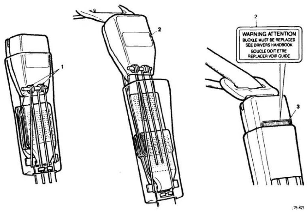
Fig. 1 Tear Loop Seat Belt
13.8.11 Front Seat Belt Buckle Unit, Renew
■ Disconnect vehicle battery ground lead.
■ Remove the front seat cushion.
- Disconnect cable connector and remove cable into seat frame.
■ Remove securing bolt, buckle unit and wavy washer.
■ To refit, carry out reversal of the above procedure.
13.8.12 Front Seat Belt, Renew
■ Position the front seat for access.
■ Disconnect vehicle battery ground lead.
■ Release 'B' post upper trim and belt aperture cover.
■ Remove cover from seat belt upper fixing.
■ Removeseat belt upper fixing and releaseseat belt anchor from height adjuster; remove wavy washer.
■ Lower the upper trim pad with seat belt onto the seat.
■ Remove 'B' post lowertrim.
■ Remove seat belt lower fixing, disconnect anchor plate and remove wavy washer.
- Release upper trim pad from seat belt. Remove upper guide fixings at 'B' post.
■ Remove seat belt reel fixings and remove reel and belt assembly.
■ Refit seat cushion.
- Secure seat belt reel to the specified torque.
■ Fit and secure upper guide plate to 'B' post.
■ Pass the seat belt through the upper trim pad.
■ Fit wavy washer to lower anchor, fit lower anchor plate and nut; tighten to specified torque.
■ Refit lower 'B' post trim panel.
■ Refit upper 'B' post trim panel.
Place wavy washer on height adjuster stud, fit belt upper anchor and nut; tighten to specified torque.
■ Fit plastic cover and split finisher.
13.8.13 Rear Inertia Seat Belt, Renew
- Remove seat cushion, rear seat squab and rear parcel tray.
■ Remove foam pad from rear shelf and remove seat belt buckle bolt.
■ Remove buckle assembly, washers and spacers.
■ Remove side seat belt buckle and the lower anchorage belt.
■ Move the belt aside and remove the upper spacer. - Remove the seat belt bracket/ body fixing and remove reel / bracket assembly.
■ Remove seat belt reel/securing bracket fixings.
■ Remove the reel and belt assembly.
■ To refit, carry out reversal of the above procedure.
13.8.14 Rear, Center, Static Seat Belt, Renew
■ Remove rear seat cushion.
■ Remove seat belt buckle bolt and remove buckle.
■ Remove washers, spacers and side seat belt buckle.
■ Remove center lap strap buckle and seat belt strap securing bolt.
■ Remove the strap and buckle assembly.
■ Remove washers, spacers and side seat belt buckle.
■ To refit, carry out reversal of the above procedure.


SECTION CONTENTS
Sub-Section Title SRO Page
i to iii ...... Preliminary Pages ...... i to iii
14.1 Working Practices 1
14.1.1 Working Practices. General 1
14.1.2. Working Practices. Handling Refrigerant 1
14.1.3 Working Practices. Handling Lubricating Oil 2
14.1.4 ...... Working Practices. System Maintenance ...... 2
14.2 ClimateControl System 3
14.2.1 Climate Control System. Description 3
14.2.2. Climate Control System. Features 3
14.3 Climate Control Panel 4
14.4 Temperature Control 6
14.4.1 Temperature Control. Coolant Circuit.... 6
14.5 Air Conditioning Control Module 7
14.5.1 Air Conditioning Control Module. Description 7
14.5.2. Air Conditioning Control Module. Interfaces 8
14.6 Control Module Fault& Condition Self-Analysis 9
14.6.1 Control Module Fault& Condition Self-Analysis. System Health 9
14.6.2. Control Module Fault& Condition Self-Analysis. System Protection 9
14.7 Air Distribution 10
14.8 ...... Refrigeration Cycle ...... 12
14.9 ...... General System Procedures ...... 13
14.9.1 General System Procedures. Leak Test 13
14.9.2 ...... General System Procedures. Charge Recovery (System Depressurization) ...... 13
14.9.3. ...... General System Procedures. Evacuating the System ...... 13
14.9.4. ...... General System Procedures. Adding Lubricating Oil (Compressor Related) ...... 13
14.9.5. ...... General System Procedures. Adding Lubricating Oil (Component Related) ...... 14
14.9.6. ...... General System Procedures. Adding Refrigerant ...... 14
14.10 Fault Diagnosis 15
14.10.1 Fault Diagnosis. Introduction 15
14.10.2 Fault Diagnosis, Functional Check 15
14.10.3 Fault Diagnosis. System Symptoms 15
14.11 System Self-Test 17
14.11.1 System Self - Test Interrogation Procedure via the Control Panel 17
14.1 1.2.... System Self - Test. Control Panel Fault Code Key .... 17
14.1 1.3.... System Self- Test Associated Faults .... 18
14.1 1.4.... System Self- Test Panel Communication Check .... 18
14.12 Manifold Gauge Set 19
14.13 System Checking With Manifold Gauge Set 20
14.1 3.1 ...... System Checking With Manifold Gauge Set. Evacuating the Gauge Set ....20
14.13.2 ...... System Checking With Manifold Gauge Set. Connecting the Manifold Gauge Set ....20
14.13.3 System Checking With Manifold Gauge Set Stabilizing the System 20
14.14 Pressure / Temperature Graph (High Side/ Ambient Temperature) 21
14.15 Pressure / Temperature Graph (Low Side/ Evaporator Temperature) 22
14.16 System Pressure Fault Classification 23


| Illustration | Jaguar Number | Description | Notes |
| not illustrated | Recovery/ Recycling/ Recharging station | See standards |
II. TORQUE TIGHTEN1 NGSPECIFICATIONS
| Fixing | lightening Torque (Nm) |
| Blower assembly to body | 4 - 7 |
| Condenser to receiver/ drier (tube nut) | 14 - 18 |
| Discharge hose to condenser (tube nut) | 22 - 28 |
| Heater/ cooler case to body | 5 - 7 |
| Hoses to compressor | 7 - 10 |
| Hoses to evaporator plate | 7 - 10 |
| Liquid line to receiver/ drier (tube nut) | 14 - 18 |
| Mountina strut to heater/ cooler case | 5 - 7 |
- SERVICE MATERIALS
| Description | Uses | Notes |
| HFC 134A - ICI Klea or equivalent | Refrigerant | Recyclable. NOT compatible with CFC 12 |
| Polyalkyleneglycol (PAG) | Compressor lubricant | Absorbs water readily. NOT compatible with mineral based oils |
IV. SERVICE DATA
| Application | Specification |
| Charae weight | 1100 g +/- 50 g |
| Lubricant capacity | 160 - 200 ml |
| Compressor pressure relief valve | Opening point 34 Bar. Closing point 27,6 Bar.Maximum leakage rate of 113 liters/minute @ 41 Bar |
| Drive belt 12 cylinder | 7 rib Polyvee; 1450 mm long |
| Drive belt tension | Burroughs method- New belt 790N; If tension falls below 270 N reset at 630 N |
| All figures apply to a cold belt | Clavis method- New belt 114 to 120 Hz; If tension falls below 70 Hz reset at 87 to 93 Hz |
| Special note | For new belt; rotate engine3 revolutions minimum and retention |
| Drive belt tension measuring point | Mid-way between crankshaft and compressor pulley |
| Drive belt 6 cyclinder | 4 rib PolyveeX 1010 mm long |
| Drive belt tension | Burroughs method- New belt 556 to 578 N; If tension falls below 245 N reset at 378 to 400 N |
| All figures apply to a cold belt | Clavis method- New belt 167 to 173 Hz; If tension falls below 85 Hz reset at 127 to 133 Hz |
| Drive belt tension measuring point | Mid-way between crankshaft and compressor pulley on the upper run |
| Standard for Recovery / Recycle / Recharge Equipment. | |
| Feature Requirement | |
| Recovery rate | 0,014 - 0,062 m3 / min. (1,36 kg in20 minutes) |
| Cleaning capability | 15 parts per million (ppm) moisture; 4000 ppm oil; 330 ppm non condensable gases in air |
| Oil separator | With hermetic compressor and automatic oil return |
| .Moisture indicator | Sight glass type, sensitive to 15 ppm minimum |
| Vacuum pump | 2 stage 0,07 - 0,127 m3 / min. |
| Filter Replaceable with moisture indicator | |
| Charge | Selectable charge weight and automatic delivery |
| Hoses | Dedicated HFC 134A port connections. |
| Charge pressure | Heating element to increase pressure |
Climate Control Systems
14.1 WORKING PRACTICES
14.1.1 General
Be aware of, and comply with all health and safety requirements, whether they be legislative or common sense. This applies to conditions set both for the operator and workshop.
Before commencing any repair or service procedure, disconnect the vehicle battery ground connection and protect the vehicle where appropriate, from dirt or damage.
Work in a well ventilated, clean and tidy area (Fig.
Keep all components and tools clean.
Recovery Recycle and Recharge equipment must comply with, or exceed the standard detailed in the preliminary pages.
Fig. 1
14.1.2 Handling Refrigerant
Wear eye protection at all times. Use gloves, keep skin that may come into contact with HFC 134A covered. Should refrigerant come into contact with your eyes or skin; wash the affected area with cool water and seek medical advice, do not attempt to treat yourself.
Avoid breathing refrigerant vapour, it may cause irritation to your respiratory system.
Never use high pressure compressed air to flush out a system. Under certain circumstances HFC 134A + compressed air + a source of combustion (welding and brazing operations in the vicinity), may result in an explosion and the release of pounds.
HFC 134A and CFC 12 must never come into contact with each other (Fig. they will form an inseparable mixture which can only be disposed of by incineration.
Do not vent refrigerant directly to atmosphere, always use Jaguar approved recovery equipment. Remember, HFC 134A is costly but recyclable.
continued
Because HFC 134A is fully recyclable it may be 'cleaned' by the recovery equipment and re-used following removal from a system.
Leak tests should only be carried out with an electronic analyzer which is dedicated to HFC 134A. Never use a CFC 12 analyzer or naked flame type.
Do not attempt to 'guess' the amount of refrigerant in a system, always recover and recharge with the correct charge weight. In this context do not depress the charge or discharge port valves to check for the presence of refrigerant.
14.1.3 Handling Lubricating Oil
- Avoid breathing lubricant mist, it may cause irritation to your respiratory system.
- Always decant fresh oil from a sealed container and do not leave oil exposed to the atmosphere for any reason other than to fill or empty a system. PAG oil is very hygroscopic (absorbswater) and will rapidly become contaminated by atmospheric moisture.
PAGoil is NOT compatible with previously used mineral based oils and must NEVER be mixed (Fig. 1). Do not re-use oil when it has been separated from refrigerant, following a recovery cycle. Dispose of used oil safely.
14.1.4 System Maintenance
When depressurizing a system do not vent refrigerant directly to atmosphere, always use Jaguar approved recovery equipment.
- Always decant compressor oil from a sealed container and do not leave oil exposed to the atmosphere for any reason other than to fill or empty a system. PAG oil is very hygroscopic and will rapidly become contaminated by atmospheric moisture.
- Plug pipes and units immediately after disconnection and only unplug immediately prior to connection. Do not leave the system open to atmosphere.
It is not necessary to renew the receiver drier whenever the system has been 'opened' as previously advised - see note this page. However, if a unit or part of the system is left open for more than five minutes, it may be advisable to renew the receiver drier. This guidance is based on U.K average humidity levels; therefore, locations with lower humidity will be less critical to moisturecontamination of the unit. It must be stressed that there is not a safe' period for work to be carried out in: ALWAYS plug pipes and units immediately after disconnection and only remove plugs immediately prior to connection.

Note: The receiver / drier MUST be renewed if the compressor has failed or if it is suspected that debris may be in the system.
- If replacement parts are supplied without transit plugs and seals DO NOT use the parts. Return them to your supplier.
Diagnostic equipment for pressure, mass and volume should be calibrated regularly and certified by a third party organization.
Use extreme care when handling and securing aluminium fittings, always use a backing spanner and take special care when handling the evaporator.
- Use only the correct or recommended tools for the job and apply the manufacturer's torque specifications.
14.2 CLIMATE CONTROL SYSTEM
14.2.1 Description
The climate control system in the 1995 model year saloon has a centre mounted heater / cooler unit with separate blower assemblies, one LH and one RH. Heating temperature control is effected by means of a coolant flow valve and circulation pump.
For models fitted with air conditioning, cooling is provide by passing air through the evaporator, which is situated immediately behind the heater/ cooler case inlet ducts.
Electric motors with integral potentiometers are used to position all flaps.
Note: There are no vacuum operated components in the system.
14.2.2 Features
- Self diagnostic control system with error codes.
○ Actuator 'self check'. - Display element check.
Note: These features will be helpful for initial trouble shooting and where Jaguar Diagnostic Equipment (JDE) is not available.
- 'Soft touch' logic controls.
Serial link from panel to control module (A/CCM).
○ LCD display for temperature, status and fan speed.
○ Variable fan speed, whether in automatic or manual mode. - Manual air flow distribution over-rides.
○ Compensated air flow with regard to vehicle speed. - Rear footwell outlets.
- Rear face outlets.
- Scavenge system closed circuit temperature control.
- Heated front screen (where fitted).


14.3 CLIMATE CONTROL PANEL
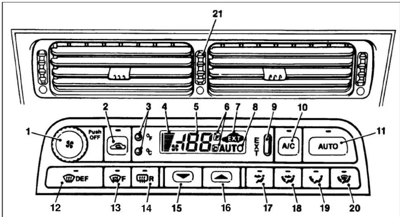
Fig. 1 Control layout (see key listing below)
The following description of the various control panel functions is provided as a brief over-view to assist in function checking. Further information concerning the control panel to component interface may be found in the fault finding procedures (this section) or the Electronic Diagnostic Manual (EDM).
Note: The system may be activated by any one of four commands. a) AUTO button item1; b) DEFROST button item 12; c) A/C button item10; d) OFF switch item 1.
- Combined push for OFF and rotary FAN SPEED control. The speed of the two fans is changed by clockwise (to increase) or anti-clockwise rotation of the knob. Operation of the control, (push) OFF or (rotate) FAN over-rides the AUTO selection and cancels the 'AUTO' display.
- RECIRCULATE AIR push-on / push-off button and state lamp, used to prevent outside air being drawn into the cabin. There are two modes: a) Press and immediate release; provides timed recirculation of five (5) minutes. b) Press and hold for two (2) seconds; 'latches' the mode until operator override.
- Temperature scale SELECTOR for Celsius or Fahrenheit.
- FANS SPEED display bar graph.
- TEMPERATURE numeric display for demand and exterior.
- Selected temperature SCALE temperature numeric display.
- EXTERIOR temperature option display.

- AUTO selection display.
- EXTERIOR temperature selection button. There are two modes: a) Press and immediate release; provides timed display of four (4) seconds. b) Press and hold for two (2) seconds; 'latches' the mode until operator over-ride.
- A/C push-on/ push-off button will either engage or disengage (as indicated by the state lamp) the refrigeration system compressor. The state lamp is also used as a compressor speed fault indicator, see System protection, this section.
- AUTO push-on button and state lamp. When selected and the state lamplit, the A/C mode is selected and control of demand temperature, fans speed, and air distribution is automatic. AUTO is cancelled by selection of any 'distribution' button, A/C off, or manual FANS SPEED.
- DEFROST push -on/ push-off button and state lamp. When engaged, air is distributed to the screen at maximum fans speed and the heated front screen elements (where fitted) are energized. The heated front screen is automatically timed for a six (6) minute cycle but may be cancelled by pressing the HEATED FRONT SCREEN button. Automatic temperature control is retained and the fans speed may be manually reduced. Deselection will return the system to the previous state and selection of AUTO will resume automatic system control.
- The push-on/push-off (F) button with state lamp manually controls the HEATED FRONT SCREEN (where fitted). This facility allows rapid screen de-icing using laminated electrical heating elements to supplement the hot air defrost.
- The push-on/push-off (R) button with state lamp manually controls the HEATED REAR SCREEN and door mirror glass heating elements for a timed cycle of; screen twenty (20) minutes and mirrors eleven (11) minutes.
Note: The state lamp will remain lit after the mirror timer has gone through its 11 minute cycle and will not go out until either completion of the 20 minute screen cycle or manual override.
- TEMPERATURE decrease buttonin 1° C or 1° F steps.
- TEMPERATURE increase button in 1° C or 1° F steps.
Note: Automatic temperature control operates over the range 17°C to 31°C (61°F to 90°F). Extreme limits selected by items 15 and 16 ('Lo' and 'Hi') provide maximum cooling or heating at maximum fans speed.
- FACE level manual distribution over-ride push-on / push-off button and state lamp.
- Bi LEVEL (foot and face) manual distribution over-ride push-on / push-off button and state lamp.
- FOOT level manual distribution over -ride push-on / push-off button and state lamp.
- DEMIST (screen and foot) level manual distribution over-ride push-on / push-off button and state lamp.
Note: Selection of AUTOwill over-ride any manual setting and deselection of any manual distribution will revert the system to AUTO distribution.
- FACE VENT TEMPERATURE CONTROL thumb-wheel. Situated between dash centre face level vents to reduce face air outlet temperature relative to that of the foot-well.


14.4 TEMPERATURE CONTROL
14.4.1 Coolant Circuit
The main coolant system supplies liquid at engine temperature to the heater matrix to provide heat to the vehicle interior. Unlike previous air blend/ constant matrix temperature systems, in-car temperature is now controlled by mixing recirculatedcoolant in the heater circuit with engine-temperaturecoolant. Matrix temperature is controlled by a valve which opens to raise temperature (admit engine coolant) and closes to reduce it (recirculates coolant within the circuit). The coolantflow valve operates on a six (6)second 'duty cycle', during which it may be open for whatever period thecontrol system dictates.FACE vent airtemperature of howeveriscontrolledbythe'cool air by-passdamper' which allows incoming air to flow around the topof the the heater matrix and thus remain unheated.
Because the engine coolant pump is driven proportionally to engine speed, the coolant delivery rate changes with engine revolutions thus causing temperature variations. To stabilize the flow through the matrix, and thus the temperature, an electrically driven circulation pump has been introduced into the system.
![graph LR A["1"] --> B["2"] B --> C["3"] C --> D["4"] E["5"] --> F["6"] style A fill:#f9f,stroke:#333 style B fill:#ccf,stroke:#333 style C fill:#cfc,stroke:#333 style D fill:#fcc,stroke:#333 note right of A: 1. Engine note right of B: 2. Coolant flow valve note right of C: Circulation pump note righ…](/content/2026/06/1254020/images/e2eb9aa82d72edede839ea1ce6656fe958312195f2ed56f034540d405d678d50.jpg)
Fig. 1 Coolant circuit, schematic view
14.5 AIR CONDITIONING CONTROL MODULE(A/CCM)
14.5.1 Description
The climate control system peripherals communicate with the A/CCM via three main device categories, plus the vehicle power supply and ground connections.
| Manual Inputs | Control panelFace Vent Temperature Control |
| Automatic inputs | Temperature and solar sensorsFlapservo motor potentiometersCirculation pump& coolant flow valvePower transistor(fan speed control)Compressor lock sensor (12 cylinder only)Instrument pack (coolant temp& road speed) (engine revolutions via engine control module) |
| outputs | Blower motors (Left& Right)& associated relaysFlapservo motorsHeated front/ rear screens & exterior mirror relaysMotorized in-car aspiratorCompressor clutch request to engine control module (not heater-only cars)Circulation pump relayCoolant flow valve |


14.5.2 ControlModule Interfaces
![graph TD A["CONTROL PANEL"] --> B["A / CCM"] B --> C["A Temperature Control"] C --> D["Air Flow Speed Control"] D --> E["Air Inlet Control"] E --> F["External temp. display"] B --> G["A / CCM"] G --> H["Solar sensor"] G --> I["Motorized in-car aspirator"] G --> J["Ambient temp. sensor"] G --> K["Eva…](/content/2026/06/1254020/images/1bf785d25c549867163e3a93c43d35358d794e7d77211dbab08730aa7ac01402.jpg)
Fig. 1 Schematic view A I CCM Inputs & Outputs

14.6 CONTROL MODULE FAULT & CONDITION SELFANALYSIS
14.6.1 System Health
The climate control system has a 'self-test' facility, accessible from the control panel. The self test sequence has two basic modes:
System error information is stored in the A/CCM up to a maximum of five faults. Should a fault occur there will be an audible 'beep' and the message 'Er' will be displayed on the control panel LCD for approximately five (5) seconds after ignition on. Please note that this will happen only once in any ignition switch cycle. The error source may be accessed by the procedure described in 'Self Test System Diagnosis', this section.
Panel communication check may be initiated by following the instruction in 'Self Test System Diagnosis', this section.
Note: Displayed error codes are NOT directly related to Jaguar Diagnostic Equipment (JDE) but more detailed fault related information may be accessed using Portable Diagnostic Unit (PDU).
14.6.2 System Protection
Power to the compressor clutch may be cut should either the engine management or air conditioning control systems detect certain conditions; these conditions may be caused by Faultor Demand and can be classified thus:

Fault
- Engine coolant overheat,
- Refrigerant excessive pressure.
- Refrigerant, insufficient pressure or low charge weight.
- Speed differential between compressor and crankshaft caused by belt slippage or compressor seizure (indicated by A/C state lamp flashing once per second) – 12 cylinder engine only. This feature, 'lock sensing' is fully explained in the EDM.
Demand
- Engine maximum power requirement
Electrical system drain at engine idle.


14.7 AIR DISTRIBUTION
(Refer to illustrations on this and next page)
Air is drawn from the plenum chamber into the heater / cooler case at the lower front right and left hands sides. All air must first pass through the evaporator (not fitted to heater only cars) and then through the heater matrix for in-car distribution.
When cooler air than that available from the other outlets is desired at the FACE vents, air by-passes the matrix via the 'cool air by-pass damper' within the range cold to hot.
The flaps for FOOT, COOL AIR, CENTRE VENT, RH & LH RECIRCULATION and DEFROST are electrically driven by individual motor / potentiometer units.

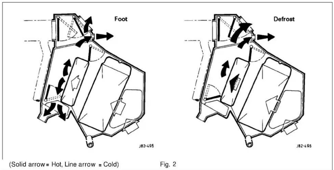
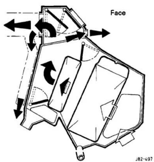


Fig. 1
The Compressor draws low pressure, low temperature refrigerant from the evaporator and by compression, raises refrigerant temperature and pressure. High pressure, hot vaporized refrigerant enters the Condenser where it is cooled by the flow of ambient air. A change of state occurs as the refrigerant cools in the condenser and it becomes a reduced temperature high pressure liquid.
From the condenser the liquid passes into the Receiver / Drier which has three functions,
a) Storage vessel for varying system refrigerant demand.
b) Filter to remove system contaminants.
c) Moisture removal via the dessicant.
With the passage through the receiver/drier completed the, still high pressure liquid refrigerant enters the Expansion Valve where it is metered through a controlled orifice which has the effect of reducing the pressure and temperature.
The refrigerant, now in a cold atomized state, flows into the evaporator and cools the air which is passing through the matrix.
As heat is absorbed by the refrigerant it once again changes state, into a vapour, and returns to the compressor for the cycle to be repeated (Fig.1).
There is an automatic safety valve incorporated in the compressor which will operate should the system pressure be in excess of 41 bar. The valve will reseat when the pressure drops below 27,6 bar.
Note: Thedivision of HIGH and LOW side is simply the system pressure differential created by the compressor discharge (pressure), suction (inlet) ports and the relative inlet and outlet ports of the expansion valve. This differential is critical to system fault diagnosis and efficiency checks.
Twelve Cylinder Vehicles only:
Dual pressure switch: This two-function pressure switch cuts electrical power to the compressor clutch if the system pressure is outside of the range of 2 Bar (1st Function) to 30 Bar (2nd Function).
Six Cylinder Vehicles only:
There are two switches incorporated into the high side of the system which have the following functions:
a) Trinary; This three function pressure switch, cuts electrical power to the compressor clutch should the system pressure not be in a range of 2 bar (1st function) to 30 bar (2nd function). The switch also provides a ground signal to operate the appropriate relay (within the 'Stribel,' unit) to energize both engine cooling fans when maximum A/C cooling is required. Operation pressure, 20 bar input (3rd function). b) Pressure Switch Slow Cooling Fans; When the system pressure is 12 bar, medium A/C demand, the operation of this switch connects both engine cooling fans in series to operate at half battery voltage and so, half fan speed.
![graph TD A["1"] --> B["2"] B --> C["3"] C --> D["4"] D --> E["5"] E --> F["6"] F --> G["7"] G --> H["8"] H --> I["9"] I --> J["10"] J --> K["11"] K --> L["12"] L --> M["13"] M --> N["14"] N --> O["15"] O --> P["16"] P --> Q["17"] Q --> R["18"] R --> S["19"] S --> T["20"] T --> U["21"] U --> V["22"]…](/content/2026/06/1254020/images/843ed61dbd8b78bb418eb7cc22f2f282aff0227aa69455f9ae4303fdf8436fa9.jpg)
- Compressor
- Condenser
- Receiver/ Drier
- Expansion Valve
- Evaporator
- Pressure switch- Dual type on 12cyl & Trinary on 6cyl
Fig. 1
14.9 GENERAL SYSTEM PROCEDURES
14.9.1 Leak Test
Faults associated with low refrigerant charge weight and low pressure may be caused by leakage. Leaks traced to mechanical connections may be caused by torque relaxation or joint face contamination. Evidence of oil around such areas is an indicator of leakage. When checking for nonvisible leaks use only a dedicated HFC 134A electronic analyzer and apply the probe all round the joint/connection.
Should a leak be traced to a joint, check that the fixing is secured to the correct tightening torque before any other action is taken.
Do not forget to check the compressor shaft seal and evaporator.
CAUTION: Never use a dedicated CFC 12 or naked flame type analyzer.
14.9.2 Charge Recovery (System depressurization)
The process of HFC 134A recovery will depend on the basic characteristics of your chosen recovery/ recycle/recharge equipment, therefore, follow the manufacturer's instructions carefully.
Remember that compressor oil may be drawn out of the system by this process, take note of the quantity recovered so that it may be replaced.
CAUTION: Observe all relevant safety requirements.
Wear suitable eye and skin protection
Do not mix HFC 134A with CFC 12.
Do not vent refrigerant directly to atmosphere and always use Jaguar approved recovery / recycle / recharge equipment.
Take note of the amount of recovered refrigerant, it will indicate the state of the system.
14.9.3 Evacuating the System
This process, the removal of unwanted air and moisture, is critical to the correct operation of the air conditioning system. The specific procedures will vary depending on the individual characteristics of your chosen recovery/ recycle / recharge equipment and must be carried out exactly in accordance with the manufacturers instructions. However, it is recommended that the initially only the HIGH side valve be opened at the start of the procedure. After a short time a small depression should be seen on the LOW side, at which point the LOW side valve may be opened and the evacuation process completed. If a vacuum is not registered on the LOW side it may indicate that the expansion valve is jammed closed or that the system is blocked. This simple check may save time and effort when the system is re-charged.
Moisture can be highly destructive and may cause internal blockages due to freezing, but more importantly, water suspended in the PAG oil will damage the compressor. Once the system has been opened for repairs, or the refrigerant charge recovered, all traces of moisture MUST be removed before recharging.
14.9.4 Adding Lubricating Oil - Compressor Related
The amount of oil drawn out during a recovery procedure will be dependent on the state of the system and the rate of recovery. The quantity will be approximately 30 to 40 ml; this may vary, and the figure is given only for guidance.
The oil separator vessel in the recovery equipment must be clean and empty at the start of the process so that the quantity of oil which is drawn out may be accurately measured.
Oil may be added by three methods, 1 and 2 being direct into the system and 3 with the compressor off the vehicle;
-
Via the recovery/ recycle/ recharge station.
-
Proprietary oil injector.
Note: Equipment manufacturer's instructions must be adhered to when using direct oil introduction.
- Directly into the original, or new unit, because of rectification work to the existing compressor, or the need to fit a new compressor.
Original
From an existing compressor, drain the oil into a measuring cylinder and record the amount. Flush the unit out with fresh PAG oil and drain thoroughly, Replenish the compressor with the same amount of PAG oil that was originally drained out and immediately plug all orifices ready for refitting to the vehicle.
New
Drain and discard the transit lubricating oil from a new compressor before it is be fitted. An adjustment must then be made to avoid over-filling the system, by taking into account;
a) the quantity found in the original compressor.
b) the quantity deposited in the recovery equipment oil separator from the charge recovery operation.
Typical example:
Drained from original compressor 50 ml
Recovered from oil separator 40 ml
Quantity to be put in new compressor 50 + 40 = 90 ml
Please note that the discrepancy between the cumulative figure of recovered and drained oil and the nominal capacity of 180 ml is caused by normally unrecoverable oil being trapped in components such as the condenser, receiver/drier or evaporator.
The previous statements apply even if a problem has occurred due to oil leakage. The amount of oil lost due to leakage is generally small, so to avoid over-filling please follow the example.
If however the recovery process has not been necessary because refrigerant has also been lost, then ONLY replace the quantity drained from the original compressor.
14.9.5 Adding Lubricating Oil- Component Related
Should a major component such as condenser, receiver/ drier or evaporator be renewed then an adjustment to the system oil level must be made. This may be carried out in the same way as the examples for the compressor except for the fact that trapped oil within any one of these components cannot normally be drained. Therefore, a nominal amount of oil should be substituted in addition to that recovered from the recovery station separator.
Condenser Add 40ml
Evaporator Add 40ml
Receiver/drier NO adjustment
CAUTION: Always decant fresh oil from a sealed container and do not leave oil exposed to the atmosphere. PAG oil is very hygroscopic(absorbs water) and will rapidly attract atmospheric moisture.
PAGoil must NEVER be mixed with mineralbased oils.
Do not re-use oil following a recovery cycle, dispose of it safely.
14.9.6 Adding Refrigerant
In order that the air conditioning system may operate efficiently it must contain a full refrigerant charge. The indications of some system defects, and the results of certain tests, will show that a low charge is the most probable cause of the fault. In such cases the charge should be recovered from the system, the weight noted, and the correct amount installed.
Should refrigerant be added in liquid form, initial engine start-up revolutions must NOT exceed 2000 RPM for a period of (2) two minutes. If the engine speed is excessive, compressor damage may occur due to the lubricating oil and the liquid refrigerant being initially forced around the system as a 'slug', thus taking oil away from the compressor. These marginal lubrication conditions in the compressor will cease as the refrigerant becomes gaseous.
Never attempt to 'guess' the amount of refrigerant in a system, always recover and recharge with the correct charge weight; this is the only accurate method.
CAUTION: If oil was drawn out during the recovery process, the correct amount may be added directly from your recovery / recycle /recharge station (ifso equipped) prior to the 'charging process'.
It must be stressed that the need to protect compressor oil from moisture is vital, observethe procedures in HANDLING LUBRICATING OIL and those concerning excessive engine revolutions.
14.10 FAULT DIAGNOSIS
14.10.1 Introduction
It is very important to positively identify the area of concern before starting a rectification procedure. A little time spent with your customer to identify the conditions under which a problem occurs will be beneficial. Relevant criteria are: Weather conditions, ambient temperature, intermittent or continuous fault, airflow fault, temperature control fault, distribution fault and air inlet problem.
14.10.2 Functional Check
This simple 'first line check' will allow you to ascertain whether the system is operating within its design parameters, without recourse to (JDE). Please carry out the following, in order.
- Start engine and attain normal running temperature.
Presss AUTO to display selected temperature and illuminate AUTO & AJC state lamps.
Rotate FAN to increase or decrease lower speed, verify bar graph representation.
Operate A/C to toggle on or off. Because the compressor can be inhibited by the engine management system, ensure that the engine temperature is normal and that the ambient is above 5°C.
Operate RECIRC, state lamp should be lit and the flap behind the blower grille open.
Operate distribution buttons in turn, verify correct air distribution and relevant state lamp.
Operate DEFROST, check max fans and air to front screen.
Cycle TEMPERATURE to 'Hi' and 'Lo' to verify demanded variations and display operation. Note that extremes will provide max heat or cold independent of in-car temperature. - Operate EXT to toggle between ambient and control temperatures.
Operate HFS and HRW to note timer and mirror operation.
○ Initiate System Self Test to check for, and extract, stored faults should any of the above not perform as stated.
14.10.3 System symptoms
There are five basic symptoms associated with air conditioning fault diagnosis. The following conditions are not in order of priority.
No Cooling
- Is the electrical circuit to the compressor clutch functional?
- Is the electrical circuit to the blower motor(s) functional?
- Slack or broken compressor drive belt.
- Compressor partially or completely seized.
- Compressor shaft seal leak.
- Compressor valve or piston damage (may be indicated by small variation between HIGH & LOW side pressures relative to engine speed).
○ Broken refrigerant pipe (causing total loss of refrigerant). - Leak in system (causing total loss of refrigerant) – possible code 23.
- Blocked filter in the receiver drier.
- Evaporator sensor disconnected - possible code 13.
Pressure switch faulty- possible code23.


Insufficient Cooling
- Sluggish blower motor(s).
- Restricted blower inlet or outlet passage
- Blocked or partially restricted condenser matrix or fins.
- Blocked or partially restricted evaporator matrix.
- Blocked or partially restricted filter in the receiver drier.
- Blocked or partially restricted expansion valve.
- Partially collapsed flexible pipe.
- Expansion valve temperature sensor faulty (this sensor is integral with valve and is not serviceable).
Excessive moisture in the system.
Air in the system. - Low refrigerant charge - possible code 23.
- Compressor clutch slipping.
- Blower flaps or distribution vents closed or partially seized – possible codes 41 or 46.
Coolant flow valve not closed. - Evaporator sensor incorrectly positioned
Note: Should a leak or low refrigerant be established as the cause of INSUFFICIENT COOLING, follow the procedures Recovery/Recycle/Recharge, this section, and observe all refrigerant and oil handling instructions.
Intermittent Cooling
- Is the electrical circuit to the compressor clutch consistent?
Is the electrical circuit to the blower motor(s) consistent? - Compressor clutch slipping?
- Motorized in-car aspirator or evaporator temperature sensor faulty, causing temperature variations – possible codes 11 or 13.
- Blocked or partially restricted evaporator or condenser.
Noisy System
- Loose or damaged compressor drive belt.
- Loose or damaged compressor mountings.
- Compressor oil level low, look for evidence of leakage.
- Compressor damage caused by low oil level or internal debris.
Blower motor(s) noisy.
Excessiverefrigerant charge, witnessed by vibration and 'thumping' in the high pressure line (may be indicated by high HIGH& high LOW side pressures). - Low refrigerant charge causing 'hissing' at the expansion valve (may be indicated by low HIGHside pressure).
Excessive moisture in the system causing expansion valve noise. - Air-lock in water pump*.
Insufficient Heating
- Coolant flow valve stuck in the closed position.
- Motorized in-car aspirator seized.
Cool air by-pass damper stuck or seized - possible code 43. - Blocked or restricted blower inlet or outlet.
- Low coolant level.
- Blower fan speed low.
Coolant thermostat faulty or seized open. - Water pump inoperative or blocked
- Air-lock in matrix*.
Note: * Please see Sections 4.1 and 4.2 for specific coolant fill / bleed procedures. Electrical faults may be more rapidly traced using (JDE), please refer to the (EDM).
14.11 SYSTEM SELF-TEST
14.11.1 Interrogation Procedure via the Control Panel
| Action | Result |
| Simultaneously hold AUTO and RECIRC - Switch ignition to ON | Display element check |
| Press AUTO | Any stored fault NUMERIC code (IfZERO appears there are no stored codes) |
| Press FACE | Scroll through stored faults (maximum of 5) |
| Simultaneously press FACE and HRW | Clear stored fault codes (may need to be repeated for each fault) |
| Press RECIRC (Press FAN to skip actuator check) | Initiate actuator check (Actuator codes20 through 27*) |
| Press FAN | Exit error check mode |
14.1 1.2 Control Panel Fault Code Key
| Fault Code | Item | Description |
| 0 | Normal Operation | No fault codes present, wait 30 seconds for system self-check. |
| 11 | Motorized In-car Aspirator | Open /short in sensor circuit. Panel fault codes are not stored for motorized in-car aspirator motor failure. |
| 12 | Ambient Temperature Sensor Open | / short circuits. |
| 13 | Evaporator Temperature Sensor Open | / short circuits. |
| 14 | Water Temperature Input | Instrument pack output. |
| 15 | Heater Matrix Temperature Sensor | Open / short circuits. |
| 21 | Solar Sensor Open | / short circuits. |
| 22 | Compressor Lock Signal - 12 cylinder and supercharged 6 cylinder engines only. | Open /shortcircuits. Low gas charge, low compressor oil, loose belt. |
| 23 | Refrigerant Pressure Switch | Open /short circuits. Low gas charge* |
| 24 | Face Vent Demand Potentiometer. | Open / short circuits |
| 31 | LH Fresh/ Recirc. Potentiometer | Open /short circuitin potentiometer. feed.Note: In certain circumstances, the motor can over-travel and log further faults. Cycling the ignition two or three times after rectification of the fault will cure this. |
| 32 | RH Fresh/ Recirc. Potentiometer | |
| 33 | Cool Air by-pass Potentiometer | |
| 34 | Defrost Vent Potentiometer | |
| 35 | Centre Vent Potentiometer | |
| 36 | Foot Vent Potentiometer | |
| 41 | LH Fresh/ Recirc. Motor | Checkfor short/ open circuits in motor drive lines. Motor flap sticking/jammed. |
| 42 | RH Fresh/ Recirc. Motor | |
| 43 | Cool Air by-pass Motor | |
| 44 | Defrost Vent Motor | |
| 45 | Centre Vent Motor | |
| 46 | Foot Vent Motor |
Note: In ambient temperatures below 0° C, the system may logfault code 23 because the low ambient causes a temporary low gas pressure. Where the ambient temperature rise above 40° C, and if the engine is close to overheating, feed to the compressor clutch may be cut and code 23 registered.*
14.11.3 Associated Faults
Other symptoms that may exist without storing fault codes:
| No heat | Airlock in system.Electric water pump inoperativeCoolant flow valve stuck closedFaulty engine coolant thermostat |
| One vent failing to open close | Broken linkage. |
| Poor airflow | Blower motors - incorrect operation |
14.11.4 Panel Communication Check
| Action | Result |
| Simultaneously hold FACE and FAN – Switch ignition to ON | Panel communication with FACE, FOOT & FACE, FOOT, SCREEN & FOOT, DEFROST, RECIRC lines checked - State lamps will illuminate if all is OK. Unlit state lamp means continuity faultfor that specific link. See EDM for full check. |
14.12 MANIFOLDGAUGE SET
The manifold gauge set is a most important tool for tracing faults and system efficiency assessment. The relationship to each other of HIGH and LOW pressures and their correlation to AMBIENT and EVAPORATOR temperatures must be compared to determine system status (see Pressure/Temperature graphs in Sub-Sections 14.14 & 14.15). Because of the heavy reliance upon this piece of equipment for service diagnosis, ensure that the gauges are calibrated regularly and the equipment is treated with care.
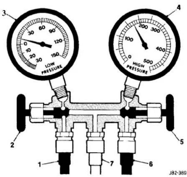
1 Low side service hose-BLUE
2 Low side hand valve- BLUE
3 Low pressure compound gauge - BLUE
4 High pressure gauge -RED
5 High side hand valve - RED
6 High side service hose-RED
7 System service hose- NEUTRAL
COLOUR (commonly yellow)
Fig. 1 Manifold gauge set
Manifold.
The manifold is designed to control refrigerant flow. When connected into the system, pressure is registered on both gauges at all times. During system tests both the high and low side hand valves should be closed (rotate clockwise to seat the valves). The hand valves isolate the low and the high sides from the centre (service) hose.
Low Side pressure Gauge.
This compound gauge, is designed to register positive and negative pressure and may be typically calibrated - Full Scale Deflection, 0 to 10 bar (0 to 150lbf / in2 ) pressure in a clockwise direction; 0 to 1000 mbar (0 to 30 in Hg) FSD negative pressure in a counter clockwise direction.
High Side Pressure Gauge.
This pressure gauge may be typically calibrated from 0 to 30 bar(0 to 500 lbf/in 2 ) FSD in a clockwise direction. Depending on the manufacturer, this gauge may also be of the compound type.
14.13 SYSTEM CHECKING WITH MANIFOLD GAUGESET
14.13.1 Evacuating the Manifold Gauge Set
Attach the centre (service) hoseto a vacuum pump and start the pump. Openfully both high and low valves and allow the vacuum to remove air and moisture from the manifold set for at least five minutes.
Turn the vacuum pump off and isolate it from the centre service hose but do not open the hose to atmosphere.
CAUTION: It is imperative that the vacuum pump is not subjected to a positive pressure of any degree. Therefore the pump must be fitted with an isolation valve at the centre (service hose) connection and this valve must be closed before the pump's switched off. This operation replaces the 'purge' procedure used on previous systems. Observe the manufacturer's recommendation with regard to vacuum pump oil changes.
14.13.2 Connecting the Manifold Gauge Set
CAUTION: Only use hoses with connectors which are dedicated to HFC 134A charge ports.
Attachment of the hose quick release connectors to the high and low side system ports is straightforward, provided that the high and low valves are closed and the system is NOT operational.
Assessment of system operating efficiency and fault classification may be achieved by using the facilities on your Recovery / Recharging / Recyclingstation, follow the manufacturers instructions implicitly and observe all safety considerations.
WARNING: UNDER NO CIRCUMSTANCES SHOULD THE CONNECTIONS BE MADE WITH THE SYSTEM IN OPERATION OR THE VALVES OPEN. SHOULD THE VALVES BE OPEN AND A VACUUM PUMP OR REFRIGERANT CONTAINER ATTACHED, AN EXPLOSION COULD OCCUR AS A RESULT OF HIGH PRESSURE REFRIGERANT BEING FORCED BACK INTO THE VACUUM PUMPOR CONTAINER.
14.13.3 Stabilizing the System
Accurate test gauge data will only be attained if the system temperatures and pressures are stabilized.
Ensure that equipment and hoses cannot come into contact with engine moving parts or sources of heat.
It is recommended that a free standing air mover is placed in front of the vehicle to provide air flow through the condenser / cooling system, see illustration below.
Start the engine, allow it to attain normal working temperature and set at fast idle (typically 1200 to 1500 rpm).
Select full air conditioning performance.
With all temperatures and pressures stable, or displaying symptoms of faults; begin relevant test procedures.

Fig. 1
14.14 PRESSURE/ TEMPERATURE GRAPH, HIGH SIDE/AMBIENT TEMPERATURE
(To obtain lbf/in 2 from bar, multiply the figure by 14.5)

Fig.1 High side pressure plotted against Ambient temperature
Probablecauses of faults may be found by comparing actual system pressures, registered on your manifold gauge set or recovery / recharge/ recycle station, and the pressure to temperature relationship graph for 'high side' pressures plotted in Fig. 1. The chart in Sub-Section14.16 shows the interpretation that may be made by this difference. The 'Normal' condition is that which is relevant to the prevailing ambient temperature.
14.15 PRESSURE/ TEMPERATURE GRAPH, LOW SIDE/EVAPORATOR TEMPERATURE (To obtain lbf/in 2 from bar, multiply the figure by 14.5)

Fig. 1 Low side pressure plotted against Evaporator temperature
Probable causes of faults may be found by comparing actual system pressures, registered on your manifold gauge set or recovery / recharge / recycle station, and the pressure to temperature relationship graph for 'low side' pressures plotted in Fig. 1. The chart in Sub-Section14.16 shows the interpretation that may be made by this difference. The 'Normal' condition is that which is relevant to the prevailing evaporator temperature.
Note: The system controls will prevent the evaporatortemperature from falling below 0°C. The graph is typical of HFC 134A
14.16 SYSTEM PRESSURE FAULT CLASSIFICATION
This table should be used in conjunction with the graphical representations of 'High side' pressure/ ambient temperature and 'Low side' pressure / evaporator temperature, this section.
| Low Side Gauge | High Side Gauge | Fault | Cause |
| Normal | Normal | Discharge air initially cool then warms up | Moisture in system |
| Normal to low | Normal | As above | As above |
| Low | Low | Discharge air slightly cool | HFC 134A charge low |
| Low | Low | Discharge air warm HFC | 134A charge very low |
| Low | Low | Discharge air slightly cool or frost build up at expansion valve | Expansion valve stuck closed |
| Low | Low | Discharge air slightly cool, sweating or frostafter point of restriction | Restriction in High side of system |
| High | Low | Compressor noisy | Defective compressor reed valve |
| High | High | Discharge air warm and high side pipes hot | HFC 134A charge high or inefficient condenser cooling due to air flow blockage or engine cooling fans not working |
| High | High | Discharge air warm Sweating or frost at evaporator | Expansion valve stuck open |
Note: If erratic or unusual gauge movements occur, check the equipment against a known (calibrated) manifold gauge set.


SECTION CONTENTS
| Sub-Section | Title | SRO | Page |
| i | Preliminary Pages | i | |
| 15.1 | Supplemental Restraint System(SRS) | 1 | |
| 15.1.1 | SRS. General Description | 1 | |
| 15.1.2 | SRS. Handling Undeployed Modules | 2 | |
| 15.1.3 | SRS. Emergency First Aid Procedures | 3 | |
| 15.1.4 | SRS. Safety Procedures. Handling Deployed Modules | 3 | |
| 15.1.5 | SRS. Safety Procedures. Handling Undeployed Damaged Modules | 3 | |
| 15.1.6 | SRS. Fire Hazard Information | 4 | |
| 15.1.7 | SRS. Ventilation | 4 | |
| 15.1.8 | SRS. Respiratory Precautions | 4 | |
| 15.1.9 | SRS. Eye Protection | 4 | |
| 15.1.10 | SRS. Protective Clothing | 4 | |
| 15.1.11 | SRS. Handling & Storage Precautions | 4 | |
| 15.1.12 | SRS. Modules. Assembly/Removal / Service Instructions | 4 | |
| 15.1.13 | SRS. Spillage & Leakage | 5 | |
| 15.1.14 | SRS. Scrapping Vehicles With Live Airbags | 5 | |
| 15.1.15 | SRS. Scrapping Vehicles With Deployed Airbags | 6 | |
| 15.1.16 | SRS. Disposal of Live Airbag Modules | 6 | |
| 15.1.17 | SRS. Disposal of Deployed Airbag Modules | 7 | |
| 15.2 | Instruments | 8 | |
| 15.2.1 | Instruments. General Description | 8 | |
| 15.2.2 | Instruments. Analog Display | 8 | |
| 15.2.3 | Instruments. Indicator Lamps | 8 | |
| 15.2.4 | Instruments. Liquid Crystal Display | 8 | |
| 15.2.5 | Instruments. Transducers | 8 | |
| 15.2.6 | Instruments. Panel. General | 8 | |
| 15.2.7 | Instruments. Gauges | 9 | |
| 15.2.8 | Instruments, Odometer | 10 | |
| 15.2.9 | Instruments. Trip Computer | 10 | |
| 15.2.10 | Instruments. Driver Information Messages | 10 | |
| 15.2.11 | Instruments. Illumination | 10 | |
| 15.2.12 | Instruments. General Repair Notes | 10 | |
| 15.3 | Speed Control | 11 | |
| 15.4 | Driver Ergonomics | 12 | |
| 15.5 | Battery& Charging System | 13 | |
| 15.5.1 | Battery, General | 13 | |
| 15.5.2 | Battery, Reserve Capacity | 13 | |
| 15.5.3 | Battery. Cranking Performance | 13 | |
| 15.5.4 | Battery. Electrical Data | 13 | |
| 15.5.5 | Battery. State of Charge | 13 | |
| 15.5.6 | Battery, Rate of Charge | 13 | |
| 15.5.7 | Battery. Load Test | 13 | |
| 15.5.8 | Battery, Specific Gravity Test | 14 | |
| 15.5.9 | Battery. Electrolyte Temperature Correction | 14 | |
| 15.5.10 | Battery. Health & Safety Precautions | 14 | |
| 15.5.11 | Battery. Remove & Refit | 86.15.01 | 15 |


SECTION CONTENTS
Sub-Section Title SRO Page
15.6 Power Wash & Screen Wash/ Wipe 16
15.6.1 Windscreen Wipers and Washers. General Description 16
15.6.2 Windscreen Wipers and Washers. Switch 16
15.6.2.1 Windscreen Wipers and Washers. Single Wipe Operation 16
15.6.2.2 Windscreen Wipers and Washers. Programmed Wash/ Wipe Operation 77
15.6.2.3 Windscreen Wipers and Washers. Headlamp Power Wash Operation 17
15.7 Closures Switching 18
15.8 In-Car Entertainment 19
15.9 Lamps & Lighting Logic 20
15.9.1 Lamps & Lighting Logic. Exterior Lighting. General Description 20
15.9.2 Lamps & Lighting Logic. Interior Lighting. General Description 21
15.10 Hamesses & Cables 22
15.10.1 Hamesses & Cables. Battery Power Distribution Cables. General 22
15.10.2 ...... Hamesses & Cables. Main Hamesses. General Description ...... 24
15.10.3 Hamesses & Cables. Link Hamesses. General Description 26
15.10.4 Hamesses & Cables. Harness Connectors. General Description 28
15.11 Motors and Solenoids 30
15.11.1 Motors and Solenoids. General Description 30
15.12 Relays 32
15.12.1 Relays. Engine Compartment. General Description 32
15.12.2 .... Relays. Passenger Compartment, General Description .... 34
15.12.3 Relays. Trunk. General Description 36
15.13 Control Modules 38
15.13.1 Control Modules. General Description 38
I. SERVICE TOOLS & EQUIPMENT
| Illustration | Jaguar Number | Description | Notes |
| to be issued |
II. TORQUE TIGHTENING SPECIFICATIONS
| Fixing | Tightening Torque(Nm) |
| Instrument pack to support panel | 1.8 |
| Fascia to console | 2.5-3.5 |
| Fascia to support bracket | 22-28 |
| Tunnel bracket tobody | 22-28 |
| Bolster to tunnel bracket | 1.5 |
| Instrument pack to fascia | 2.5-3.5 |
| Strut to fascia | 1.5-2.5 |
| Fascia support strut to BIW | 7-10 |
| CPU brackets to fascia | 5-7 |
| Fascia demister bracket to fascia | 1.5 |
| Fascia and air conditioning location to body | 1 |
| Air distribution box duct to air distribution box | 1 |
| Airbag carrier mounting bracket to fascia | 5-7 |
| instrument pack support bracket to fascia | 5-7 |
| Airbag bracket to fascia | 1.5-2.5 |
| Air distribution box to fascia | 1.5-2.5 |
| Airbag upper bracket to carrier | 1.5-2.5 |
| Instrument pack support bracket and strut | 5-7 |
| Fascia assembly to BIW | 22-28 |
| Airbag door brackets to fascia | 5-7 |
| Airbag door bracket to door frame assembly | 5-7 |
- SERVICE MATERIALS
| Description | Uses | Notes |
| to be issued |


15.1 SUPPLEMENTAL RESTRAINT SYSTEMS (SRS)
15.1.1 SRS Airbags, General Description
One airbag assembly is fitted on the passenger side into an aperture of the fascia (see Fig. 1) and the second assembly is fitted to the steering wheel (see Fig. 1, next page).

Fig. 1 The Passenger-side Airbag

The following procedures and precautions must be adhered to while handling, installing and testing airbag modules. Failure to adhere to these procedures could cause the airbag to inadvertently deploy, with the potential of personal injury.
The procedures and precautionary guidelines conform to the 'Handling & Storage – The Explosives Act of 1875 & 1923' and to the 'Health & Safety at work Act' of 1974, or local guidelines as appropriate.

15.1.2 HandlingUndeployed Modules
The electrically -activated airbag module contains sodium azide and sodium nitrate which are poisonous and extremely flammable substances.
Their contact with acid, water or heavy metals may produce harmful and irritating gases or combustible compounds. The airbag module is non-serviceable and must not be dismantled, punctured, incinerated or welded.
WARNING: DO NOT ATTEMPT ANY REPAIRS TO THE AIRBAG MODULE.
Never measure the resistance of the airbag module, as this may cause the airbag to deploy. Suspect modules must be returned to Jaguar Cars Ltd. or their importer for replacement.
Tampering or mishandling can result in personal injury.
Keep away from heat, sparks and open flames. Do not store at temperatures exceeding 93° Celsius (200°F).
Keep away from electrical equipment as electrical contact may cause ignition.
Do not drop or impact airbag module.
Always position module 'cover-up'.
Ensure that the connector is protected to prevent damage.

Store modules in a secure lockable cabinet.
Never position projectile material over the undeployed airbag as this can cause injury in the event of inadvertent deployment.

Do not wrap arms around module when carrying and always carry module with cover and ventsfacing away from body to avoid personal injury in the event of inadvertent deployment.
Never carry airbag module by wires or the connector.
The chemical propellant mixture deploying the airbag is a solid and therefore inhalation exposure is unlikely even if module is ruptured without deployment.
As far as practicable, avoid skin contact with, or ingestion of, the materials present after combustion. Exposure to high concentrations of propellant mixture may cause headache, nausea, blurred vision, faintness, cyanosis, lowering of blood pressure, tachycardia and shortness of breath.
WARNING: SODIUM AZIDE HAS BEEN LISTED AS AN 'EXTRAORDINARY HAZARDOUS SUBSTANCE OR CARCINOGEN BY THE STATE OF MASSACHUSETTS, USA. SODIUM AZIDE HAS BEEN LISTED ON THE 'RIGHT TO KNOW HAZARDOUS SUBSTANCE LIST' BY THE STATE OF NEW JERSEY AND IS ALSO REGARDED AS A 'SPECIAL HEALTH HAZARD SUBSTANCE BY THE STATE. THE PROPELLANT MIXTURE IS SENSITIVE TO PREMATUREIGNITION BY ELECTRICAL SOURCESIF NOT PROPERLY PROTECTED AND ISOLATED.
15.1.3 Emergency First Aid Procedures
If the airbag is ruptured without deployment and exposure to the propellant mixture occurs, observe the following first-aid treatments:
- Ingestion- Do not induce vomiting and seek prompt medical attention.
- Skin contact – Immediately wash skin with soap and water and seek medical attention.
- Eyes - Immediately flush eyes with water for at least 20 minutes and seek prompt medical attention.
○ Inhalation - Immediately move victim to fresh air and seek medical attention. - Physical trauma, eg bums, abrasions, or impact due to premature ignition or deployment of the inflator assembly -Treat symptomatically and seek prompt medical attention.
15.1.4 Safety Procedures For Handling Deployed (Fired) Modules
See 'Emergency First Aid Procedures' above.
Prevent contact of the inflator with liquids, combustibles and flammable materials. Failure to follow these instructions could result in chemical burns and personal injury.
Ensure modules are cool before handling.
After deployment the airbag surface contains small deposits of sodium hydroxide which can cause irritation to the skin and eyes.
When handling deployed airbags, always wear rubber gloves to BS 1651 grade 2 or equivalent, and chemical resistant goggles to BS 2092 grade 2 or equivalent.
After handling deployed airbags, immediately wash hands and exposed skin surface areas with mild soap and water.

15.1.5 Safety Procedures For Handling Undeployed Damaged Modules
The material inside the module is hermetically sealed and is completely consumed during deployment.
No attempt should be made to open the module as this leads to a risk of exposure to sodium azide.
In the unlikely event of gas generator being damaged, it must be examined by trained personnel before any attempt is made to remove and/or deploy.
Full protective clothing must be worn when dealing with any spillage.
Ruptured units must be stored away from acids, halogens, heavy metals and metal salts. Damaged units may produce hydrazoic acid if exposed to liquids.
Failure to comply with these instructions may result in fire, noxious fumes and severe personal injury or death.

15.1.6 Fire Hazard Information
Thermal decomposition or combustion may produce dense smoke and other dangerous fumes which in fire situations form a highly toxic explosive.
In the event of fire the surrounding area must be evacuated and all personnel kept well upwind of the area.
Fullfire fighting protective gear and a self contained breathing apparatus operating in the positive pressure mode must be worn for combating fire. Material near fires must be cooled with water spray to prevent ignition.
Fires should be allowed to burnthemselves out if not threatening to life or property. If fire is threatening to life or property use copious quantities of water to extinguish.
15.1.7 Ventilation
Locale exhaust ventilation designed by a professional engineer should be provided if vapours, fumes, or dusts are generated whilst working with airbag module.
The latest issue of the manual for recommended practices on 'Industrial Ventilation' is available from the ACGIH Committee on Industrial Ventilation, PO Box 16153, Lansing, MI 48910, USA.
The need for local exhaust ventilation should be evaluated by a professional industrial hygienist.
15.1.8 Respiratory Precautions
To prevent the inhalation of dangerous fumes and dusts, an approved mask should be worn.
15.1.9 Eye Protection
Chemical protective goggles are recommended where there is a possibility of eye contact with the propellant.
Safety glasses with side shields are recommended for all other operations.
15.1.10 Protective Clothing
Approved protective gloves, overalls and shoes / boots should beworn.
15.1.1 Handling and Storage Precautions
Do not store airbag module near live electrical equipment or circuitry. Store in a dry environment at ambient temperatures.
Good housekeeping and engineering practices should be employed to prevent the generation and accumulation of dusts. Store in compliance with all local state and federal regulations.
15.1.12 Driver And Passenger Airbag Modules Assembly / Removal / Service Instructions
Note: Before starting work, ensure ignition switch is in 'lock' position, key is removed and negativeterminal cable is disconnected from the battery. As the airbag is equipped with a back up power source and due to the risk of airbag being inadvertently deployed, wait one minute or longer before starting work.
- Disconnecting the battery cancels the memory for clock, radio, seats, mirrors, steering column and any other components using battery power. Reset memory after work is completed.
- Never use airbags from other vehicles, always use new parts.
- After work is completed, reconnect battery and perform warning light check see diagnostic manual.
- Never use electrical probes to check voltage or electrical resistance.
- Disconnect the airbag before carrying out any work on, or in the vicinity of module, or when using electric welding equipment.
- Always ensure that battery negative has been disconnected for one minute or longer before commencing any removal procedure.
15.1.13 Spillage and Leakage
If material is spilled or released, contact Jaguar Service for clean up procedures. All other personnel must be kept away from contaminated area.
Do not dispose contaminated propellant or water into storm or sanitary sewers, ground water or soil.
Spills may be reportable to local state, and/or federal authorities.
Material should be disposed of by incineration or chemical oxidation under carefully controlled conditions by specially trained individuals in accordance with local State and Federal regulations.
15.1.14 Scrapping Vehicles With Live Airbag(s)
When scrapping a vehicle with a live airbag, first deploy the airbag in accordance with following procedures. This procedure assumes airbag wiring is undamaged.
See Handling / Safety information.
If the airbag is o be removed see Airbag ModulesAssembly/Removal/Service Instructions.
Equipment required: Insulation Displacement Connectors (IDC) (Scotchloks) (two-off), battery, two-off ten meter lengths of 1mm2 wire fitted with crocodile clips at one end. (See Fig. 1).
WARNING: THE DEPLOYMENT PROCEDURE SHOULD BE PERFORMED OUTDOORS AWAY FROM OTHER PERSONNEL.
Remove any loose debris from around airbag and ensure no flammable liquids are present.
Disconnect the vehicle battery.
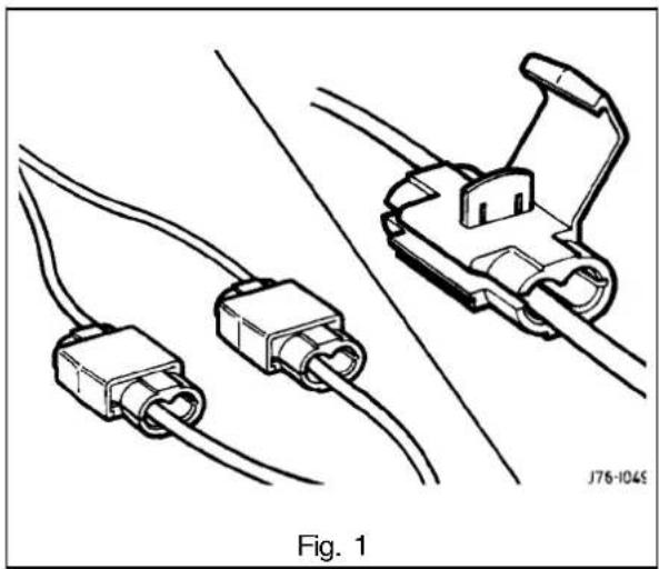
Link harness connection & deployment method
WARNING: ALWAYS CONNECT TO AIRBAG FIRST, AS THE BAG WILL DEPLOY IMMEDIATELY ON CONNECTION TO THE BATTERY.
- Remove passenger side and driver side under-scuttles / knee bolster.
■ Disconnect the airbag connector under the facia. - Look for the yellow harness connectors and cut the wires originating from the airbag just above the mating plug.
Note: The harness connected between the driver's airbag and the yellow connector has one red/purple feed wire and one pink/brown return wire. The harness connected between the passenger's airbag and the yellow connector has two red/purple feed wires and one pink/purple return wire.
- Pass a 10 meter (33ft) link harness containing two 1mm2 wires through the window aperture, and connect using an Insulation Displacement Connector (IDC) and two crocodile clips, to the airbag wires.
■ Closeall doors, leave window with lead open.
■ Ensure no personnel are in the car or in the area around the car.
■ Move back 10 meters (33ft) and connect harness crocodile clips to battery: the airbag will immediately deploy. - Allow the unit to cool for at least 20 minutes. Cooling modules should be continuously monitored to ensure heat generated does not create a fire with spilled liquids or other debris.
(continued next page)
(continued from previous page)
■ The vehicle is now to be scrapped in normal manner with module installed.

■ In the event of any problems or queries, contact Jaguar Cars Ltd. or the importer.
15.1.15 Scrapping Vehicles With Deployed Airbag(s)
- Verify that all installed airbags have been deployed or removed.
- In the event of one airbag being deployed and one not deployed, it must be assumed that the undeployed airbag is still live, therefore it must first be deployed.
The vehicle is now to be scrapped in a normal manner.
15.1.16 Disposal Of Live Airbag Modules
Note: Modulesremoved/renewed by Jaguar Service are to be returned to the importer for deployment and disposal.
CAUTION: Never use a customer's vehicle to deploy airbags.
Equipment required: Deployment Cage, IDC link harness (see 15.1.14 for details of components required), Battery, Safety Goggles to BS 2092 grade2 or equivalent, Rubber Gloves to PREN 374 class2 or equivalent, Ear Protectorsto BS EN 24869 or equivalent, Particulate Respiratorio to EN 149 grade FFP 25 or equivalent.
The deployment procedure should be performed outdoors away from other personnel.
Remove any loose debris from around airbag and ensure no flammable liquids are present.
Assemble the disposal cabinet as shown in Fig.1 in line with the following procedures:
■ Remove mesh guard from rig frame.
■ Attach guard to frame by bolting hinges to the frame.
(continued next page)
(continued from previouspage)
■ Ensure relevant plate is fitted and rotate into position.

■ Fit and secure airbag module on to plate.
■ Clamp plate down using the two toggle clamps.
WARNING: ALWAYS CONNECT TO AIRBAG FIRST, AS THE BAG WILL DEPLOY IMMEDIATELY ON CONNECTION TO THE BATTERY.
Note: The harnessconnected between the driver's airbag and the yellow connector has one red/purple feed wire and one pink/brown return wire.
The harness connected between the passenger's airbag and the yellow connector has two red/purple feed wires and one pink/purple return wire.
■ Connect the 10 meter (33ft) link harness to the airbag wires.
■ Ensure that no personnel are in the vicinity of the cabinet.
- Move back 10 meters (33ft) and connect the link harness crocodile clips to the battery; the airbag will immediately deploy.
- Allow the unit to cool for at least 20 minutes.
■ Open guard and remove deployed module.
- Seal deployed module in plastic bag ready for disposal.
■ In the event of any problems or queries, contact Jaguar Cars Ltd. or the importer.
15.1.17 Disposal Of Deployed Airbag Modules
Deployed airbag modules are to be disposed of as special waste and must comply with local environmental requirements. If in any doubt contact local authority for disposal instructions.
Note: The storage, transportation, disposal and/or recycling of airbag module components must be preformed in accordance with all applicable federal, state and local regulations including, but not limited to, those governing building and fire codes, environmental protection, occupational health and safety and transportation. Modules removed and deployed by Jaguar Service are to be returned to the importer for disposal.
15.2 INSTRUMENTS
15.2.1 General Description
The instruments measure, monitor and display data relevant to the vehicle's performance. Data is received from sensors positioned at various locations around the vehicle via two multi-pin sockets located at the rear of the instrument panel and is than presented using three different visual display methods described as follows:
15.2.2 Analog Display
This is used to display road speed, engine speed, oil pressure, battery condition, fuel level and coolant temperature.
15.2.3 Indicator Lamps
These indicate the presence of any hazard / fault conditions or operational actions.
15.2.4 LCD (Liquid Crystal Display)
This single line, six digit seven segment display is normally used to display the odometer reading out can also be used to display vehicle condition messages associated with particular warning lamps and trip computer information.
15.2.5 Transducers
These devices listed as follows transmit vehicle condition to the instruments:
○ Engine Coolant Temperature Transmitter
Low Coolant Level Probe
Oil Pressure Transmitter - AJ16/V12
Fuel Gauge Tank Unit - AJ16/V12
Note: Fault conditions and their causes displayed by the instruments and warning lamps are covered in more detail by further information contained within the Electrical Diagnostic Manual.
15.2.6 Instrument Panel, General

- 24 Way Connector
-
4% Way Connector
-
Identification Label
- Bulb Holder
Fig. 1 Instrument Panel, Rear View

- Tachometer
- Speedometer
- Battery Condition
- Fuel Gauge
- Oil Pressure
- Coolant Temperature
- Odometer /Trip Computer Display
- Primary Warning Indicators (RED)
- Exhaust Temperature
- Low Oil Pressure
- Seat Belt Not Fastened
- Boot Open
- Door Open
- Coolant Level
- Air Bag Fault
-
Status / Warning Lamps
-
Hand Brake On (RED)
- Brake System Fault (RED)
- Main Beam On (BLUE)
- Direction Indicator Right (GREEN)
- Status / Warning Lamps
- Direction Indicator Left (GREEN)
- Traction Control Off (GREEN)
- Transmission Sport Mode (GREEN)
- Charging Fault (RED)
- Check Engine (AMBER)
- Low Fuel Level (AMBER)
- Anti-Lock Fault (AMBER)
- Traction Control Fail (AMBER)
- Bulb Fail (AMBER)
- Washer Fluid Level (AMBER)
- Transmission Fault (AMBER)
Fig. 1 Instrument Panel, Front Mew
Note: The 'Premium Unleaded Fuel Only' caution is added to the Federal Market vehicles, also 'PARK BRAKE and 'BRAKE' replace international symbols used in all other markets.
Note: Six cylinder vehicle version shown; the tachometer red-line on 12cylinder vehicles starts at 6000 RPM.
The front of the PECUS-programmable instrument panel features 6 analog gauges, 22 warning lamps/ tell tales and a Liquid Crystal Display (LCD), the rear of the panel accommodates two PCB mounted connectors, one 24-way connector, one 48-way connector, one instrument panel identification label and 14 light bulbs arranged groups of seven on either side. Three power inputs and two ground inputs are provided for 'POWER UP' and 'POWER DOWN' sequence, the three power inputs comprising battery, ignition and auxiliary. The instruments are protected by a housing / lens assembly.
1527 Gauges
The two major gauges are tachometer and speedometer, and the four minor gauges indicate battery condition, fuel level, oil pressure and coolant temperature.
Each gauge is contained in a sealed non-serviceable can and must be renewed as a complete unit in case of any damage.
CAUTION: Extremecare should be exercised when renewing instrument panel components to avoid damage to the delicate indicator needles.
15.2.8 Odometer
With the ignition 'OFF' the odometer is permanently displayed but not illuminated. With the ignition 'ON' the odometer is displayed and also illuminated.
Trip information or driver information messages may be displayed instead of the 'ODO'. By pressing the 'ODO' button once or twice the trip and driver information messages can be deleted and the 'ODO re-displayed.
Note: The odometer value is not stored within the LCD module.
15.2.9 Trip Computer
This provides information on the vehicle's speed, fuel usage and distance traveled all of which are calculated by a micro processor.
The controls, part of the fascia switch assembly, are located on the right-hand side pod positioned to the right-hand side of the steering column.

15.2.10 Driver Information Messages
Two fault messages, FLUID-AIRBAG are displayed via the LCD in conjunction with relevant warning lamps.
If an airbag fault exists or the brake fluid is low, a message will automatically be displayed on the LCD and the relevant warning lights illuminated. Should both faults exist at the same time, each message is displayed alternatively for approximately 2 seconds.
Messages may be cancelled by pressing the ODO button which allows the LCD to return to its last displayed message. The warning lamps will not be extinguished. If the fault is not repaired the message(s) and the warning lamp(s) will be re-displayed when the ignition is switched on.
15.2.11 Illumination
Warning indicator lamp illumination is controlled by a microprocessor located inside the instrument panel.
The seven right-hand warning indicators are primary warning lamps illuminating 'RED and the seven left-hand warning indicators are secondary warning lamps illuminating 'AMBER'
The eight lower lamps area mixture of status and warning lamps.
With the ignitionOFF the LCD is not illuminated.
With ignition'ON' and side lights 'OFF' the LCD is illuminated at maximum brightness.
With the ignition on and side lights 'OFF' the LCD is dimmed as are the gauges.
The long life type bulbs are enclosed by orange and brown coloured bulb holders which must never be interchanged. Replacement bulbs must always be of the same colour.
CAUTION: Always disconnect the battery ground lead before commencing with any instrument renewal procedure.
15.2.12 General Repair Notes
After lens removal do not rest instrument panelface down as this causes damage to the delicate gauge needles. Avoid scratching the gauge faces and ensure cleanliness when handling the panel.
To minimize the risk of damage and contamination to the instrument panel, all repairs must be carried out in a non- static and dust - free environment. Avoid touching connector pins and pcb components to minimize risk of static damage.
The instrument panel has two different types of bulb holders each of which must be located correctly when changing the bulbs.
15.3 SPEED CONTROL
Information to be issued with Amendment 1


15.4 DRIVER ERGONOMICS
Information to be issued with Amendment 1
| UK Market | Rest of World | |
| Battery Capacity | 72A / 20hr | 92A / 20hr |
| Rapid discharge current | 590A at -18°C | 700A at -18°C |
| Rapid discharge voltage | 7.5V at -18°C | 7.5V at -18°C |
| Reserve capacity duration | 25A at 135 minutes | 25A at 170minutes |
| Open circuit voltage | 12.70V | 12.37V | 12.11V | 11.74V | 11.30V |
| Specific gravity voltage (temperature compensated hydrometer) | 1.280 1.225 | 1.180 1.120 | 1.050 | ||
| % Charged | 100 75 | 50 | 25 | 0 |
| Battery Condition | Charge Rates | ||
| Specific gravity (temp. compensated hydrometer) | State of charge | Maximum Slow charge rate/times | charge rate/times |
| 1.180 to 1.225 | 50% to 75% | 20A/120 min. | 5A/240 min. |
| 1.120 to 1.180 | 25% to 50% | 30A/120 min. | 10A/240 min. |
| 1.050 to 1.120 | 0 to 20% | 40A/120 min. | 15A/240 min. |
| Test Load | Electrolyte Temperature (°C) | Min. Voltage Under 15sec. Load |
| Load to half battery cold cranking amps (UK): 295A 15.55Load to half battery cold cranking amps (ROW): 295A | 21.11 | 9.6V |
| 9.5V | ||
| 10.00 | 9.4V | |
| 4.44 | 9.3V | |
| -1.11 | 9.1V | |
| -6.66 | 8.9V | |
| -12.22 | 8.7V | |
| -17.77 | 8.5V |
15.5.8 Specific Gravity Test
The specific gravity of the electrolyte determines the level of the float in the liquid. With the float in a high position, the specific gravity is high and when the specific gravity is low the float sinks to the lower position.
Using a hydrometer the specific gravity readings are taken when the liquid level crosses the scale on float. This should give a accurate indication of the state charge of the battery.
The volume and the specific gravity of the electrolyte varies with the change in temperature.
15.5.9 Electrolyte TemperatureCorrection
For every 10° C below 15° C subtract 0.007 from the hydrometer reading, and for every 10° C above 15° C add 0.007 to the hydrometer reading.
Note: Use only distilled water for topping up electrolyte. The electrolyte must not exceed 51.66°C during charging. If after 30 minutes charging the battery current is not equal or greater than 3A, dispose of the battery.
15.5.10 Health and Safety Precautions
As batteries contain sulphuric acid and explosive mixtures of hydrogen and oxygengases, it is strongly recommended that protective clothing is worn.
Avoid spilling acid to prevent damage to clothing and skin bums.
If accidentally spilled or splashed on clothing or skin, rinse with cold water. As a neutralizer, a solution of baking soda or ammonia and water may be used.
In the event of skin or eye contact rinse the affected areas with water and should this not be sufficient seek medical attention.
Any trace of acid spilled or splashed on the vehicle should be rinsed with clean water.
BEFORE AND WHilst Working with the battery be aware of the following safety precautions
- particularly during charging, highly explosive hydrogen is emitted.
- do not smoke when working near the battery.
- avoid sparks, short circuits or other sources of ignition.
- switch off current before connecting or disconnecting any electrical terminals.
- always disconnect battery ground lead first and reconnect last.
- ensure battery is charged in a well ventilated area.
- switch off the charger before disconnecting.
WARNING: WHEN PREPARING ELECTROLYTE OF A DESIRED SPECIFIC GRAVITY, ALWAYS POUR THE CONCENTRATED ACID SLOWLY INTO THE WATER AND NOT WATER INTO THE ACID. HEAT IS GENERATED WHEN MIXING ACID WITH WATER, HENCE ADD SMALL AMOUNTS OF ACID AND STIR SLOWLY INTO THE WATER. ALLOW TO COOL IF NOTICEABLE HEAT DEVELOPS. EXCEPT FOR LEAD LINED CONTAINERS, ALWAYS USE NON - METALLIC CONTAINERS AND/ OR FUNNELS. DO NOT STORE ACID INEXCESSIVELY WARM LOCATIONS OR DIRECT SUNLIGHT.FUEL VAPOUR IS EXTREMELY FLAMMABLE, HENCE GREAT CARE MUST BE TAKEN WHilst WORKING ON THE FUEL SYSTEM.
15.5.11 Battery, Remove & Refit
SRO 86.15.01

Fig. 1
Remove
- Open the trunk lid.
■ Remove the battery cover. - Disconnect and insulate the battery negative lead (1 Fig. 1).
■ Disconnect and insulate the positive lead(2 Fig. 1). - Remove the battery (3 Fig. 1).


Refit
Refitting is a reversal of the removal procedure.

15.6 POWER WASH & SCREEN WASH/ WIPE
15.6.1 Windscreen Washers & Wipers, General Description
The single windscreen wiper blade is controlled by a windscreen wiper/washer switch located on the right-hand side of the steering column switchgear (see Fig. 1).
The windscreen wiper motor, part of the wiper motor assembly operates at slow or fast speeds and drives the lever assembly, a single arm and blade via a crank.
On V12 engined vehicles the wiper motor assembly is mounted to the front of the bulkhead with the motor protruding into the plenum chamber, whilst on AJ16 engined vehicles the wiper motor assembly is mounted into the same position, but with the motor protruding into the engine compartment.
For wipe and wash operation a mixture of water and special 'Jaguar Windscreen Fluid' is drawn from the PVC reservoir assembly by two electrically controlled pumps and is then distributed via flexible feeder hoses interconnected using 'TEE' pieces to the screen wash jets and to heated power wash jets (wherefitted). The ends of power wash hoses are fitted with 'quick fit' fluid connectors.
The two pumps, one for screen wash and one for headlamp power wash are externally fitted to the reservoir located at the front right-hand side of the engine compartment. Contained within the reservoirs pullupneck is a serviceable filter.
The screen wash jets with independently adjustable eyeballs are mounted on the plenum chamber finisher and the temperature of the fluid passing through the jets is controlled from an ambient temperature sensor fitted near the inlet of the right-hand side air duct.
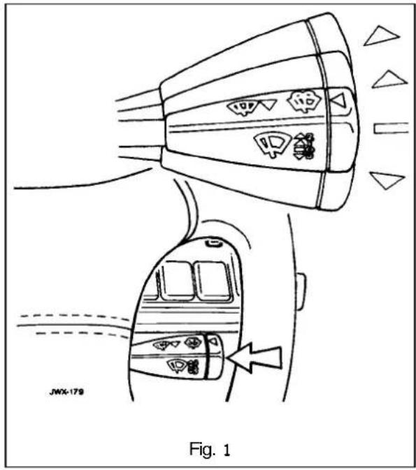
The fluid temperature for each of the headlamp wipe wash operation is controlled by self regulating, heated power wash jets mounted on to either side of the bumper.
Each powerwashjet is protected by a cover supplied with an integral cover-to-bumperseal. The cover snap fixes into the bumper.
15.6.2 windscreen Wiper and Washer Switch
This switch only operates with the ignition switch in position '11' and has the following functions:
Position 0 The wind screen wiper is switched 'OFF' and parked.
Position 1: Normal speed wiper operation is obtained by pushing the switch lever up one position.
Position2: High speed wiper operation is obtained by pushing the switch lever fully up.
PositionD: To obtain intermittent wiper operation the switch lever is pushed down and released.
The delay period will vary with vehicle speed. To cancel the function repeat the procedure.
15.6.2.1 Single Wipe Operation
To obtain a single sweep of the wiper blade, the lever is pulled towards the steering wheel and released.
Note: The intermittent/flick wipe operations are both at slow speed and they are controlled by a Central Control Module (CCM), which also controls the headlamp power wash operation.
15.6.2.2 Programmed Wash / Wipe Operation
The end of the switch lever must be pressed inwards for the windscreen wash and wipe operation. Wash / wipe continues for as long as the lever is pressed.
When released, the windscreen wiper stops immediately and the wiper blades sweep for a further three wipes.
On pressing the end of the switch lever inward and then releasing it, the windscreen washers operate for approximately two seconds before stopping, whilst the wiper blade continues for a further three wipes.
Note: If the end of the switch lever is pressed while the washer fluid warning light is illuminated, the windscreen washers, but not the wiper blade continues to operate.
15.6.2.3 Headlamp Power Wash Operation (where fitted)
The headlamp power wash operates only when the programmedwasher/ wipe function is selected and the side lights are 'ON'
The headlamp power wash does not operate if the windscreen washer reservoir fluid lever is low. This is indicated by the washer fluid level warning light illuminating.
Note: The headlamp power wash only operates on the 1st and every 6th succeeding cycle of the programme wash / wipe switch, after the ignition switch has been turned to position'll'.


15.7 CLOSURESSWITCHING
Information to be issued with Amendment 1
15.8 IN - CAR ENTERTAINMENT (ICE)
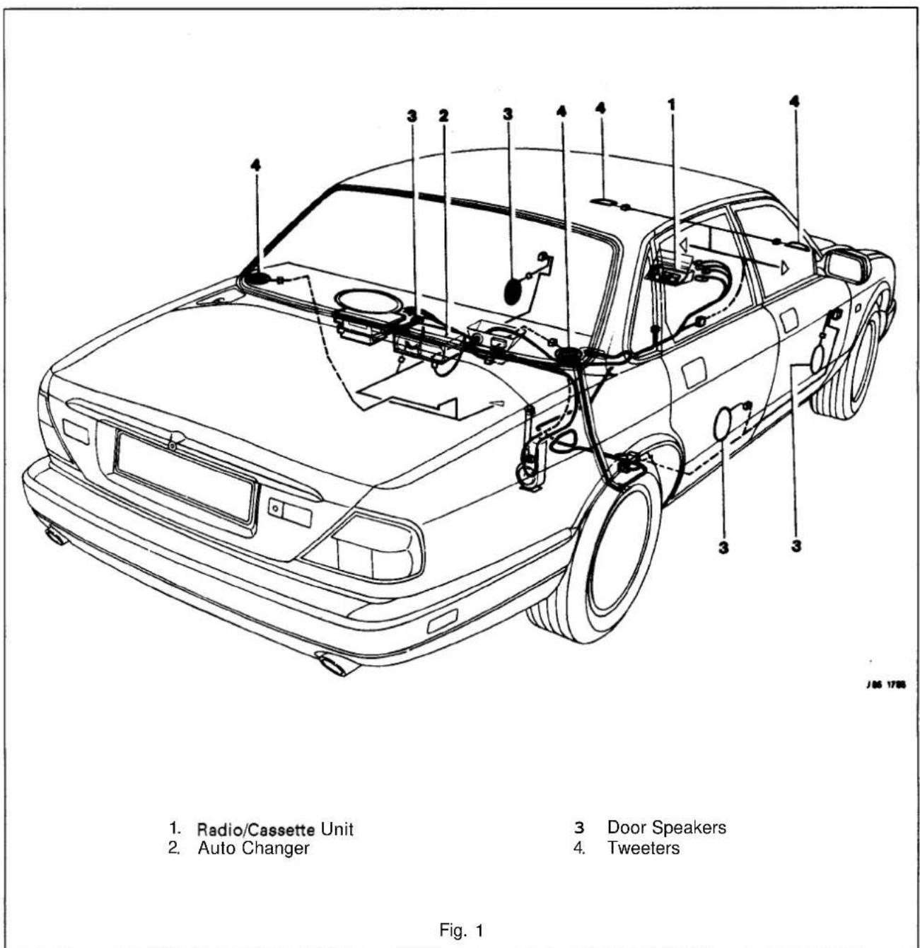
5.8.1 General Description
The plan viewin Fig.1 shows the locations of the In-Car Entertainment (ICE) equipment. This consists of a radio cassette playerfitted inside an aperture of the centreconsole switch assembly, a compact disc auto-changer located inside the trunk, four speakers fitted to the front and rear doors and four tweeters of which two are located on either side of the crash-roll dash below the windscreen and two on either side of the rear shelf.
The vehicle has an electrically operated, retractable aerial fitted on the offside rear fender.
15.9 LAMPS & LIGHTINGLOGIC
15.9.1 Exterior Lighting, General Description

Fig. 1 Exterior Lighting
Figure 1 indicates all exterior lamps located at the front, the sides and the rear of the vehicle.
The exterior lamps consisting of two headlamp assemblies containing the inboard and outboard headlamp units incorporating the pilot bulbs, the fog lamps, the front direction indicator lamps and side marker lamps fitted through the front bumper, the repeater lamps positioned on the fenders, the number plate lamps and the rear lights incorporating tail, stop, flasher and fog lamps.
15.9.2 Interior Lighting, General Description

The interior lamps consist of E-Post lamps with or without map lights, a map light combined with switch fitted to the roof console, sun visor lamps, door courtesy / hazard lamps and a trunk lamp.
Other interior illumination bulbs are fitted within the various switch assemblies.


15.10 HARNESSES & CABLES
15.10.1 Battery Power Distribution Cables, General Description

Figure 1 shows a plan view of the battery power distribution cables and their distribution points. This illustration is to be read in conjunction with the following table. To avoid any accidents such as electric shocks, always disconnect the battery negative lead from the battery negative terminal before disconnecting any of the listed cables.
Key to Fig. 1, Battery Power Distribution Cables, page 22.
| Battery Power Distribution Cable | Number |
| Rear heel board/ Fuse box power lead | 1 |
| Terminal to terminalpost link lead | 2 |
| Engine bay / fuse box power cable LH | 3 |
| Starter to alternator cable | 4 |
| Engine bay / fuse box power cable RH | 5 |
| Starter cable | 6 |
| Battery positive extension cable | 7 |
| Battery positive cable | 8 |
| Battery negative cable | 9 |
| Trunk fuse box power cable | 10 |


15.10.2 Main Harnesses, General Description

Fig. 1 shows a plan view of the main harness runs inside the trunk, the passenger compartment and the engine bay. The illustration is to be read in conjunction with the following table. To avoid any accidents such as electric shocks, always disconnect the battery negative lead from the battery negative terminal before disconnecting any of the listed cables.

| Main Harness | Number |
| Rear Lamp | 1 |
| LH Rear Door | 2 |
| LH Rear Door (Passenger) | 3 |
| Fascia | 4 |
| Enaine / PI | 5 |
| Left Forward | 6 |
| RH Front Bumper | a |
| Right Forward | 9 |
| RH Front Door | 10 |
| Console | 11 |
| Cabin | 12 |
| RH Rear Door | 13 |
| In-Car Entertainment | 14 |
| Trunk | 15 |


15.10.3 Link Harnesses, General Description

Fig. 1 shows a plan view of the link harness runs inside the trunk, the passenger compartment and the engine bay. The illustration is to be read in conjunction with the following table. To avoid any accidents such as electric shocks, always disconnect the battery negative lead from the battery negative terminal before disconnecting any of the listed cables.
Key to Fig. 1, Link Harnesses, page 32.
| Link Harness | Number |
| Side Marker Link Harness (LH) | 1 |
| Roof Harness | 2 |
| Passenger Memory / Seat Harness Link | 3 |
| Electronic Gearbox | 4 |
| Air Condition Harness | 5 |
| Front Screen Heaters | 6 |
| Airbag | 7 |
| Cooling Fans | 8 |
| Alternator Suppression | 9 |
| Power steering Speed Sensor | 10 |
| Steering Column | 11 |
| Memory / Seat (Driver's) | 12 |
| Side Marker (RH) | 13 |


15.10.4 Harness Connectors, GeneralDescription

Fig. 1 shows a plan view of the harness connectors physically linking all the harnesses located in the trunk, the passenger compartment and the engine bay.
The illustration is to be read in conjunction with the following table. To avoid any accidents such as electric shocks, always disconnect the battery negative lead from the battery negative terminal before disconnecting any of the listed cables.
Key to Fig. 1, Harness Connectors, page 34.
| From Location | To Location | Connector No. | Number |
| In-Car Entertainment | Trunk | IC 002 | 1 |
| LH Rear Door | Cabin | CA 013 | 2 |
| Console | Cabin | CC 018 / 004 | 3 |
| Fascia | Console | FC 007 | 4 |
| Cabin | LH Forward | LS 003 | 5 |
| Cabin | LH Front Door (Passenger) | CA 001 | 6 |
| Fascia | Cabin | FC 005 | 7 |
| LH Forward | Engine | PI 059 /066 | 8 |
| LH Forward | LH Front Bumper | BL 001 | 9 |
| RH Forward | Engine | PI 001 / 061 | 10 |
| RH Forward | RH Front Bumper | BR 001 | 11 |
| Console | Engine | PI 063 | 12 |
| Fascia | Cabin | FC 006 | 13 |
| Cabin | Door | CA 009 | 14 |
| Cabin | RH Forwards | RS 003 | 15 |
| ICE | Fascia | IC 007 | 16 |
| Console | Cabin | CC 003 / 005 | 17 |
| RH Rear Door | Cabin | CA 013 | 18 |
| ICE | Cabin | IC 022 | 19 |
| Cabin | Boot | BT 004 | 20 |
| Rear Lamp | Boot | BT 005 | 21 |


15.11 MOTORS & SOLENOIDS
5.1 1.1 General Description
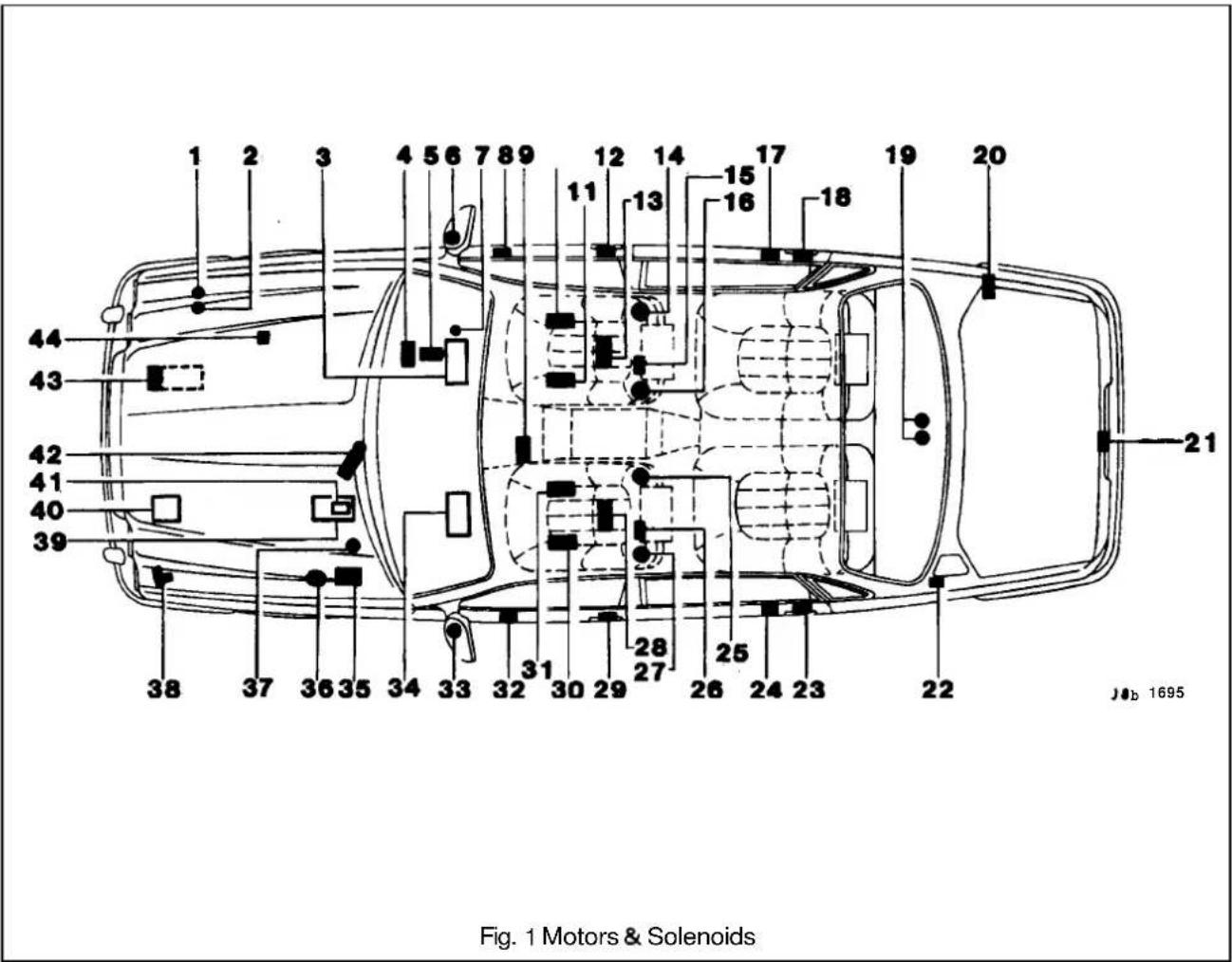
Fig. 1 shows a plan view of all motors located inside the trunk, the passenger compartment and the engine bay. The motors drive various devices to perform certain functions such wipe/ wash operations, window lift operations, seat operations etc.
In order to carry out remove and refit operations, the annotated illustration is to be read in conjunction with the table shown on the following page. This lists all the motors and solenoids.
Some motors can be accessed by removing the various trims, the carpet, or carpet sections, other can be located through carrying outa visual inspection around the engine bay, the cab and the trunk.
To avoid any accidents such as electric shocks, always disconnect the battery negative lead from the battery negative terminal before disconnecting any of the listed cables.
Key to Fig 1, Motors & Solenoids, page 36.
| Motors & Solenoids | Number |
| Power Wash | 1 |
| Power Wash | 2 |
| RH Blower (AC) | 3 |
| Steering - Tilt | 4 |
| Steering - Reach | 5 |
| Driver's Mirror | 6 |
| Ignition Key Solenoid | 7 |
| Window Lift | 8 |
| Sunshine Roof | 9 |
| Memory / Seat - Rise / Fall (Rear) | 10 |
| Memory / Seat - Rise / Fall (Front) | 11 |
| Key Lock (Door) | 12 |
| Memory / Seat - Fore / Aft | 13 |
| Memory / Seat - Recline | 14 |
| Lumbar Pump Motor | 15 |
| Memory / Seat - Head Rest | 16 |
| Rear Window Lift | 17 |
| Rear Door Lock | 18 |
| Fuel Pump (Double) | 19 |
| Electrical Aerial | 20 |
| Trunk Lock | 21 |
| Filler Cap (Solenoid) | 22 |
| Rear Door Lock | 23 |
| Window Lift | 24 |
| Passenger Seat - Recline | 25 |
| Passenger Seat - Head Rest | 26 |
| Lumbar Pump Motor | 27 |
| Passenger Memory / Seat - Fore / Aft | 28 |
| Passenger - Door Lock | 29 |
| Passenger Memory / Seat - Rise / Fall (Front) | 30 |
| Passenger Memory / Seat - Rise / Fall (Rear) | 31 |
| Passenger Window Lift | 32 |
| Mirror | 33 |
| LH Blower (AC) | 34 |
| ABS Pump / Motor Unit | 35 |
| Traction Control / Actuator | 36 |
| A / C Water Pump & Water Valve Solenoid | 37 |
| Cruise Control Pump | 38 |
| Starter Solenoid | 39 |
| Starter | 40 |
| Wiper | 41 |
| Alternator | 42 |
| A/ C Compressor Clutch | 43 |
| (SCM) Steering Control Module Transducer | 44 |


15.12 RELAYS
15.12.1 Engine Compartment Relays, General Description
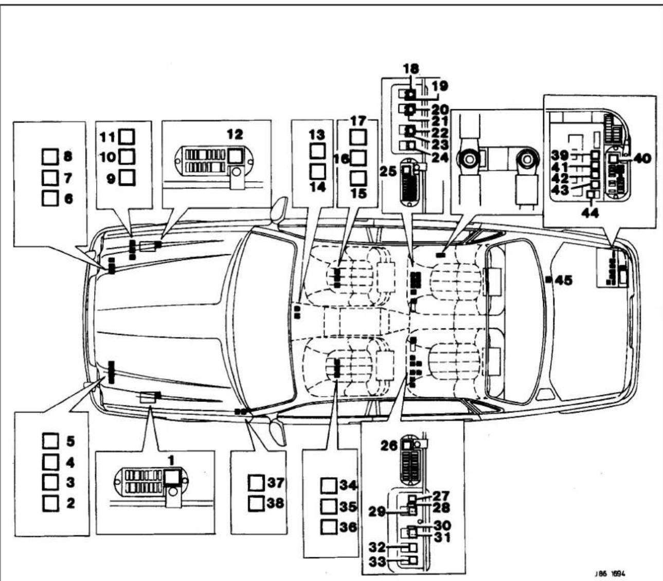
Fig. 1 Engine Compartment Relays
In order to locate individual relays, Fig.1, showing all relay locations within the engine compartment, is to be read in conjunction with the following table. The numbers indicating the relays on the illustration correspond to the numbers in the right-hand column. To remove and refit individual relays, open the bonnet, locate the faulty relay, unplug and renew.
Key to Fig. 1, Engine CompartmentRelays, page 14.
| SRO | Relays | Location | Color | AJ16 | V12 | Number |
| B6.55.04 | Horn | Engine compartment, inside the left hand side fuse box. | Blue | All Models | All Models | 1 |
| Starter Motor Solenoid | Engine compartment, behind left hand head lamp assembly. | Black | All models | All Models | 5 | |
| 18.30.34 | Air-Conditioning Water Pump | see starter motor solenoid. | Black | All Models | All Models | 4 |
| Wiper Motor On/Off | see starter motor solenoid. | Black | All Models | All Models | 2 | |
| Wiper Fast/ Slow | see starter motor solenoid. | Black | All Models | All Models | 3 | |
| 18.30.71 | EMS Engine Management System Control | Engine compartment, behind right hand head lamp assembly. | Black | All Models | - | 8 |
| Ignition Coil | see EMS control. | Black | - | All Models | 9 | |
| PIMain Relay | see EMS control. | Black | - | All Models | 8 | |
| 18.30.34 | Air Pump | see EMS control. | Black Air Injection only | Air Injection only | 7 | |
| 86.55.08 | Air Conditioning Compressor Clutch | see EMS control. | Black Air Con only - Model only | All Models | 6 | |
| Relay Case | Black/ White Stripe | Non Aircon. Models only | - | 6 | ||
| Relay Case | Engine compartment, on the right hand side inner wing valance. | Black/ White Stripe | Non Power Wash Models only | Non Power Wash Models only | 11 | |
| Power Wash | Black | Optional | Optional | |||
| Screen Wash | Black All Models | All Models | 10 | |||
| Ignition Relay | Engine compartment, inside right hand fuse box. | Blue | All Models | All Models | 12 | |


'5.12.2 Passenger Compartment Interior Relays, General Description

Fig.1 shows the relays inside the passenger compartment located under the rear seats behind the heel boards, under the centre console wood veneer, on the A-Post near the Servotronic Steering Module and under the driver's and the passenger's seats. To gain access to relevant relays, remove the heel boards, or the centre console wood veneer, or the seats, or the A-Post lower trim pad.
| SRO | Relays | Location | Color | AJ16 | V12 | Number |
| 86.55.89 | Gear Shift Interlock | Below gear selector 'J' gate. | Blue | Automatic Models only | Automatic Models only | 13 |
| Keylock | Below gear selector 'J' gate. | Blue | Automatic Models only | Automatic Models only | 14 | |
| Driver's Seat Height Control (Upward) | On seat panel below driver's seat. | Violet | UK& ROW Manual Seat only | - | 15 | |
| Driver's Seat Height Control (Downward) | On seat panel below driver's seat. | Violet | UK& ROW Manual Seat only | - | 16 | |
| Passenger Seat Height Control (Upward) | On seat panel below passenger's seat. | Violet | UK& ROW Manual Seat only | - | 34 | |
| Passenger Seat Height Control (Downward) | On seat panel below passenger's seat. | Violet | UK& ROW Manual Seat only | - | 35 | |
| Driver's Seat Heater | On seat panel below driver's seat. | Blue | UK& Manual Seat only | - | 17 | |
| Passenger Seat Heater | On seat panel below passenger's seat. | Blue | UK& Manual Seat only | - | 36 | |
| RH Front Screen Heater | Left hand side footwell on front 'A' post, behind cover. | Blue | Optional Optional | 37 | ||
| LH Front Screen Heater | Left hand side footwell on front 'A' post, behind cover. | Blue | Optional Optional | 38 | ||
| Ignition All Models | Fuse box assembly RH side heelboard. | Blue | All Models | 25 | ||
| Ignition | Fuse box assembly LH side heelboard. | Blue | All Models | All Models | 26 | |
| Air-conditioning Isolate | Behind RH side heelboard. | Blue | All Models | All Models | 23 | |
| LH Blower | Behind RH side heelboard. | Blue | All Models All Models | |||
| RH Blower | Behind RH : heelboard. | Blue | All Models All Models | |||
| LH Blower high speed | Behind RH side heelboard. | Blue | All Models All Models | 18 | ||
| RH Blower high speed | Behind RH side heelboard. | Blue | All Models All Models | 20 | ||
| Deadlock front left/rear right | Behind LH side ard | Violet | Not NAS or Japan | Not NAS or Japan | 30 | |
| Deadlock front right/rear left | Behind LH side heelboard. | Violet | UK & Europe only | UK & Europe only | 31 | |
| Door Lock | Behind LH side heelboard. | Violet | All Models | All Models | 28 | |
| Door Unlock | Behind LH side heelboard. | Violet | All Models | All Models | 29 | |
| Driver's Door Unlock | Behind LH side heelboard. | Violet | USA & Canada only | USA & Canada only | 27 | |
| Mirror Heater | Behind RH side heelboard. | Violet | All Models | All Models | 24 | |
| Puddle Lamps | Behind LH side heelboard. | Blue | All Models | All Models | 33 | |
| 86.55.78 | Cigar Lighter | Behind RH side heelboard. | Blue | All Models | All Models | 22 |
| 86.55.74 | Fuel Flap Lock | Behind LH side heelboard. | Violet | All Models | All Models | 32 |
15.12.3 TrunkRelays, General Description

Fig.1 shows all relays located inside the trunk. To locate and renew relays, open the trunk lid, remove the wheel floor carpet board, followed by the carpeted battery/fuse cover and the back panel carpet board.
Key to Fig. 1, Trunk Relays, page 18.
| SRO | Relays | Location | Color | AJ16 | V12 | Number |
| 18.30.70 | Fuel Pump Single | Trunk, inside electrical carrier. | Blue | All Models | All Models | 41 |
| Fuel Pump | Trunk, inside electrical carrier. | Blue | Supercharged only | Secondary Fuel Pump | 45 | |
| 86.55.19 | Rear Screen Heater | Trunk, inside electrical carrier. | Blue | All Models | All Models | 43 |
| 86.55.73 | Trunk Lid Release | Trunk, inside electrical carrier. | Violet | All Models | All Models | 44 |
| Accessory Socket | Trunk, inside electrical carrier. | Blue | All Models | All Models | 42 | |
| 86.56.10 | High Mount Stop Lamp | Trunk, inside electrical carrier. | Blue | Where fitted | Where fitted | 39 |
| 86.56.11 | Fuse box Assembly/Aux. Positive | Trunk, inside electrical carrier. | Blue | All Models | All Models | 40 |
15.13 CONTROL MODULES(CM)

15.13.1 General Description
Fig. 1 shows a plan view of the control module locations for the vehicle.
In order to locate and renew modules, the illustrations should be read in conjunction with the following table indicating each module's location.

| Location | Number | ||
| Universal garage door opener | Roof console panel | 11 | |
| 86.52.01 | Security & Locking Control Module (SLCM) | LH side upper wheel arch, inside the trunk below fuel filler pipe | 13 |
| Sunroof | Roof console panel. | 10 | |
| 86.91.83 | Mirror memory controlSeat/ Mirror Memory (Passenger.) | Mounted inside driver's& passenger's seat. | 914 |
| 19.75.21 | Speed control | Behind passenger knee bolster. | 2 RHD20 LHD |
| 86.80.24 | Air conditioning (A/CCM) | RH side of air conditioning unit. | 1 |
| Transmission control | Behind passenger knee bolster. | 16 RHD(12&6)7 LHD(12&16) | |
| Engine Management | RH side footwell in front of 'A' post behind cover. | 6 (12&16) | |
| BPU (Body Processor Unit) | Behind passenger knee bolster. | 19 RHD3 LHD | |
| ABS (Anti-lock Braking System& Traction Control (where fitted). (ABS/TC CM) | Engine compartment belowanti-lock braking system modulator. | 18 RHD4 RHD | |
| Bulb failureRearFront | Trunk inside electrical carrier box,Engine compartment behind each headlamp assembly. | 1222 & 24 | |
| Power steering | LH side footwell on'A' post, behind cover. | 17 | |
| Column/ mirror ECM | On the side of steering column. | 5 | |
| Reader exciter | Around the lock barrel of steering column. | 8 | |
| Airbag (SRS diagnostic) | Behind passenger knee bolster below the airbag module. | 15 RHD23 LHD | |
| Cooling fan (Striebel) unit | Behind bumper, LHS of vehicle | 21 |


CONTENTS
Title Page
Specification. 1995 Model Year Vehicles .... 1
Engine Management System 1
Cooling System 7
Fuel System Pump 7
Clutch 7
Manual Transmission Ratios 1
Automatic Transmission Ratios 2
Final Drive Unit Ratios 2
Climate Control System 2
Braking System 3
Steering & Suspension 4
Electrical Equipment 5
Lubricants & Fluids 7
Vehicle Weights 9
Tires 10
Snow Chains 11
Bulbs 12
Fuses 14
SPECIFICATION- 1995 MODEL YEAR VEHICLES
Engine See relevant engine service manual
Engine Management System
V12 Nippondenso
6 cyl. Lucas GEMS
Cooling System
Water pump
type Centrifugal
drive Belt
Cooling fans - 6 cyl. Two electric fans controlled by temperature sensor in radiator
Cooling fans - V12 One engine driven fan and two electric fans controlled by temperature sensor in radiator
Cooling system control .... Thermostat (two onV12)
Thermostat opening temperature 88°C
Fully open at 93,5 to 96°C
Filler cap pressure rating 1,2 bar
Fuel System Pump
one fitted on 6cyl. (3.2 Liter and 4.0 Liter normally aspirated)
two fitted on 6cyl. (4.0 Liter supercharged) and V12
Electrical, module type, fitted in the tank. Integral 70 micron filter.
Make Nippondenso
Pump type ...... Regenerative turbine
Fuel pressure (nominal) 3,0bar
Fuel pressure (supercharged) 3,7 bar max.
Second pump switches at:
4.0 Liter supercharged in at 4000 RPM
V12 load sensitiveswitching
Clutch
Plate diameter 280mm single plate, LUK
Clutch hydraulic fluid DOT4
Manual Transmission Ratios (Getrag)
First gear 3,553:1
Second gear 2,041:1
Third gear 1,400:1
Fourth gear 1,000 : 1
Fifth gear 0,755:1
Reverse 3,553:1
A1
Automatic Transmission Ratios(ZF)
First 2.48.1
Second 1.48.1
Third 1.00.1
Fourth 0.73.1
Reverse 2,09:1
Automatic Transmission Ratios (Powertrain)
First 2482.1
Second 1.482.1
Third 1.000.1
Fourth 0.750.1
Reverse 2077:1
Final Drive Unit Ratios
3.2 liter Manual 3.77:1
3.2 liter Automatic.... 4.08:1
4.0 liter Automatic 3.54:1
4.0 liter Manual 3.54:1
4.0 liter Supercharged 3.27:1
6.0 liter 3.54:1
Climate Control (air conditioning) System
Compressor Nippondenso 10PA17C
Compressor lubricant ND Oil8
Refrigerant R134A
Refrigerant Charge Weight 1100g
Braking System
Front brakes: all vehicles....Power assisted, ventilated discs,
sliding calipers: FN60 single piston
Caliper piston diameter: 60mm
Rear brakes: all vehicles ....Power assisted, ventilated discs, FN48 single piston sliding calipers
Caliper piston diameter 48mm
Disc thickness: Front .... 28mm, wear limit 27mm Rear .... 20mm, wear limit 18.5mm
Brake operation .... Vacuum power, hydraulic operation
Master cylinder ...... Bore diameter: 25,4mm
Main brake friction pad material: Front .... Jurid 518 Rear .... Jurid 101
Parking brake friction shoe material ...... Ferodo 3612
Brake servo booster assembly Boost ratio .... 6,5:1 vacuum
Anti-lock braking system (ABS)
Wheel sensors .... Electrical inductive sensors at the wheels which detect rotational speed.
ABS modulator …… Hydraulic: vehicles with traction control – contains four solenoid valves, one for each wheel; vehicles without traction control – contains three solenoid valves, one for each front wheel and one for both rear wheels.
Steering and Suspension
Note: When checking the steering geometry, use the pull-downtools front and rear to set the ride height front and rear to the following dimensions:
6 cyl.
| Front ride height | 153 ± 5mm to underside of front crossbeam |
| Rear ride height | 160 ± 5mm to underside of rear edge of A frame |
V12
| Front ride height | 143 ± 5mm to underside of front crossbeam |
| Rear ride height | 160 ± 5mm to underside of rear edge of A frame |
Note: Sportspack derivatives whose kerb height is below the above figures can have their geometry checked at that height.
Front Suspension
| Type Independent front suspension. | consisting of double wishbones with coil springs and separate dampers and anti-roll bar. |
| Dampers | Telescopic, gas pressurised |
| Caster angle | 3,0° to 6,0° and with opposing wheels within 1° of each other |
| Camberangle | 0,3° to -0,8° |
| Front wheel alignment | Totaltoe: 5 minutes in ± 10 minutes |
Rear Suspension
| Type | Fully independent rear suspension of double wishbone principle with axle shaft operating as upper wishbone incorporating coaxial springs and dampers with optional rear anti-roll bar. |
| Camber angle (at design ride height): | |
| all vehicles except supercharged | -0,75° ± 0,4° |
| supercharged only | -1,6° ± 0,4° |
| Rear wheel alignment | Total toe: 15 minutes in ± 20 minutes |
| Dampers | Telescopic, gas pressurised |
Power Assisted Steering
| Type | ZF Servotronic speed-sensitive rack and pinion |
| Number of turns lock to lock | 2,768 |
| Turning circle: | |
| (wall to wall) | 12,9m (42ft 4in) |
| (curb to curb) | 12,4m (40ft 8in) |
Electrical Equipment
Battery
UK and Europe:
Make Varta
Nominal capacity 72Ah
Earth polarity ...... Negative
All Other Markets:
Make Varta
Nominal capacity 92Ah
Earth polarity .... Negative
Generator
6cyl. (3.2 Liter and 4.0 Liter normally aspirated):
Make Nippondenso
Type L3A/H
Part No. DBC 6819
Earth polarity ...... Negative
Maximum output 120 Amps
Nominal regulated voltage 14.4V at 25°C
6cyl. (4.0 Liter supercharged):
Make Nippondenso
Type L3A/H
Part No. LNA 1800BA
Earth polarity ...... Negative
Maximum output 120 Amps
Nomina I regulated voltage 14,4V at 25°C
V12
Make Nippondenso
Type L3B/H(E)
Part No. LNA 1800AA
Earth polarity ...... Negative
Maximum output 120 Amps
Nominal regulated voltage.... 14,4V at 25°C


A1
Electrical Equipment (continued)
Starter
6 cyl.
Make and type.... Bosch DW 1,7K
Free spin speed 3000 RPM
Free spin current 90A maximum
Load running current 420A maximum
Stall 1050A
V12
Make and type.... Magneti MarelliM80R
Free spin speed 2650 RPM
Free spin current 75A maximum
Load running current 375A maximum
Stall 1000A
Windshield Wiper Motor
Make Trico
Light running speed: (after 60 seconds from cold)
Slowspeed 40 - 48 cycles
Fast speed 57-67 cycles
Light running current:
Slow speed 2.5A max.
Fastspeed 5A max.
LUBRICANTSAND FLUIDS
Engine Oil
Specification ....
A.P.I. SG / CD or
A.P.I. SH (when available)
SAE Viscosity Range ....
5w/20-20w/50
dependent on ambient temperature
Capacities
6 cyl. (3.2L and 4.0L) ....
8 liters
V12
10 liters
Manual Transmission (3.21 & 4.01)
Fluid Specification ....
Dexron IID, Dexron IIE
Capacity...
1,4 liters
Rear Axle Fluid
Specification ....
A.P.I. GL5
SAE Viscosity Rating ....
EP 90
Fluid Make &Type ....
Shell Spirax Super 90 oil
(alternative brands may be used for top-up only when Shell Spirax is not available)
Capacity (all vehicles) ....
2,1 liters
Power Assisted Steering
Preferred fluid
Dexron IIE
Alternative fluid ....
Dexron IID (use only when Dexron IIE is not available)
Capacity ....
1,0 literapproximately
Cooling System
Coolant Mixture Specification ....
50% plain water, 50% Jaguar Anti-freeze, Coolant and Corrosion Inhibitor conforming to specification ESD-M97B49A (for frost protection down to -36°C (-33°F))
Capacities:
6 cyl. (3.2L and 4.0L normally aspirated)
initial fill ....
12 liters
drain and refill ....
7.7 liters
6cyl. (4.0L SC)
initial fill ....
13,5 liters
drain and refill ....
9,25 liters
V12
initial fill...
19,2 liters
drain and refill ....
14,5 liters


A1
Braking System and Clutch System
Fluid Specification Dot 4
Make & Type. ....Jaguar Brake Fluid
Grease Points
Grease Specification N.L.G.I. Consistency No.2
Grease Type .... Multipurpose Lithium Grease
Fuel Tank
Capacity:
total refill 81 liters
indicated refill capacity 75 liters ('E' to 'F' on fuel gauge)
VEHICLE WEIGHTS
Note: Gross combination weight is the gross vehicle weight plus recommended trailer weight. All weights approximate.
| 3.2L | 4.0L (normally aspirated) | Daimler 4.0L | 4.0L SC | V12 | |
| kg | kg | kg | kg | kg | |
| Kerb weight | 1800 | 1800 | 1825 | 1875 | 1975 |
| Front axle kerb weight | 912 | 912 | 925 | 970 | 1070 |
| Rear axle kerb weight | 888 | 888 | 900 | 905 | 905 |
| Gross vehicle weight (GVW) | 2220 | 2220 | 2245 | 2295 | 2395 |
| Gross front axle weight | 1019 | 1019 | 1032 | 1077 | 1177 |
| Gross rear axle weight | 1201 | 1201 | 1213 | 1218 | 1218 |
| Gross combination weight | 3720 | 3720 | 3745 | 3795 | 3895 |
A1
TIRES
Tire Replacement And Wheel Interchanging
WARNING: UNDER NO CIRCUMSTANCES SHOULD CROSS-PLY TIRES BE FITTED.
When renewal of tires is necessary, it is preferable to fit a complete set.
Should either front or reartires only (i. not the full set) show a necessity for renewal, new tires must be fitted to replace the worn ones.
No attempt must be made to interchange tires from the front to the rear or vice-versa, as wear produces a characteristic pattern on each tire depending upon its position on the vehicle. If this position is changed after wear has occurred, the performance of the tire will be adversely affected.
It should be remembered that new tires must be balanced.
The radial ply tires specified here are designed to meet the high speed performance of this vehicle. Only tires of identical specification as shown in this section must be fitted as replacements. If two replacement tires are fitted to one axle, they must be of the same type and pattern as those on the other axle, i.e. tires must be used in sets of four of the same manufacturer and tread pattern, not intermixed.
Tire Fitments
| Tire Type | 3 2 Liter | 4.0 Liter(Normally (Daimler Aspirated) Federal | 4.0 Liter SC | 6.0 Liter&XJ12) | 6.0 Liter(UK, Euro, ROW XJ12) |
| Standard | 225 / 60 ZR16 | 225/ 60 ZR16 | - | 225 / 60 ZR16 | |
| Sports | 225 / 55 ZR16 | 225/ 55 ZR16 | - | - | 225/ 55 ZR16 |
| Supercharged | - | - | 255/ 45 ZR17 | - | - |
| Space saver(where fitted) | 115 / 85 R18 | 115 / 85 R18 | 115 / 85 R18 | 115185 R18 | 115 / 85 R18 |
Recommended tires
The following tires are recommended:
| 225/60 ZR 16 | Pirelli P4000 E |
| 225/55 ZR 16 | Pirelli P6000 |
| 225/55 ZR 16 | Dunlop SP Sport 2000 |
| 255/45 ZR 17 | Pirelli P Zero |
| 115185 R 18 | Pirelli |
Recommended Winter (Snow) Tires
Tire designation:
| 225/60 R 16 | Goodyear Eagle GW M+S |
| 225/55 R 16 | Pirelli Winter210 M+S |
| 225/55 R 16 | Michelin 330 M+S |
Only use winter tires in complete sets of the same type / size.
CAUTION: Tire directional indicators must rotate in a clockwise direction when viewed from the right-hand side of the vehicle, and in an anti-clockwise direction when viewed from the left-hand side.
The recommended pressures for winter tires are shown in the table of inflation pressures on the following page.
Table of inflation pressures (cold)
Recommended tires must be inflated to the following pressures:
| Comfort SettingSpeeds up to 160 km / h (100 mph) | Normal Setting | |||
| Bar | lbf / in2 | Bar | lbf / in2 | |
| 225 / 60 ZR16 (plus winter tires) 3.2 Liter and 4.0 Liter Normally Aspirated | ||||
| Front | 1,7 | 26 | 2,21 | 32 |
| Rear | 1,9 | 28 | 2,3 | 34 |
| 225 / 55 ZR16 (plus winter tires) 3.2 Liter and 4.0 Liter Normally Aspirated | ||||
| Front | 1,7 | 26 | 2,21 | 32 |
| Rear | 1,9 | 28 | 2,3 | 34 |
| 225 / 60 ZR16 (plus winter tires) 6.0 Liter | ||||
| Front | 1,9 | 28 | 2,3 | 34 |
| Rear | 1,9 | 28 | 2,3 | 34 |
| 225 / 55 ZR16 (plus winter tires) 6.0 Liter | ||||
| Front | 1,9 | 28 | 2,3 | 34 |
| Rear | 1,9 | 28 | 2,3 | 34 |
| 255 / 45 ZR17 4.0 Liter SC | ||||
| Front | 1,9 28 | 34 | 2,3 | |
| Rear | 1,9 28 | 34 | 2,3 | |
| 115 / 85 R18 (space saver wheel) - all vehicles (where fitted) | ||||
| Front not applicable | not applicable | 4,1 | 60 | |
| Rear not applicable | not applicable | 4,1 | 60 | |
Note: Tires other than those recommended by Jaguar must be inflated to the following cold inflation pressure: 2,9 bar (44 lbf/in 2 ) (both front and rear).
Snow Chains
- Snow chains may be fitted to rear wheels only.
- Use Jaguar snow chains.
The chains must not be used on roads which are clear of snow.
Maximum speed without snow chains fitted is 210 km/h. (131 mile/h).
Maximum speed with snow chains fitted is 48 km/h. (30 mile/h).


BULBS
| Description Capacity | Type | |
| Door guard lamp. | 12V 5W | Capless long life |
| Flasher side repeater | 12V 5W | Capless long life |
| Fog lamp - Front. | 12v 55w | Halogen H3 |
| Fog lamp - Rearguard | 12v 21w | Bayonet long life |
| Front turn indicator | 12V 21W | Bayonet long life |
| Pilot lamp | 12V 5W | Capless long life |
| Headlamp | 12V 55W | Halogen H1 |
| High mounted stop lamp (where fitted). | 12v 5 x 5W | Capless long life |
| Roof console central courtesy lamp | 12V 5W | Capless long life. |
| Roof console reading lamp | 12V 6W | Capless |
| Luggage compartment lamp | 12V 5W | Capless long life |
| License plate lamp | 12V 5W | Festoon |
| Rearturn indicator | 12v 21w | Bayonet yellow long |
| Rear quarter courtesy lamp (lower section) | 12V 5W | Capless long life |
| Rear quarter reading lamp (upper section) | 12V 6W | Capless |
| Back-up lamp | 12v 21w | Bayonet long life |
| Stop/ Tail lamp | 12V 21V 5W | Twin filament bayonet long life |
| Sun visor vanity mirror lamp | 12v1,2W | Capless 286 |
| Tail lamp | 12V 5W | Bayonet long life |
Indicator bulbs
| Bulb Designation | Holder Colour Rating | |
| Exhaust temperature warning indicator bulb Orange | 12,5V 1,2W | |
| Low oil pressure indicator bulb | Orange | 12,5V 1,2W |
| Seat belt warning indicator bulb | Orange | 12,5V 1,2W |
| Boot open warning indicator bulb | Orange | 12,5V 1,2W |
| Door open warning indicator bulb | Orange | 12,5V 1,2W |
| Coolant level warning indicator bulb | Orange | 12,5V 1,2W |
| Air bag fault indicator bulb Orange | 12,5V 1,2W | |
| Parking brake 'on' indicator bulb | Orange | 12,5V 1,2W |
| Brake system warning indicator bulb | Orange | 12,5V 1,2W |
| Main beam 'on' indicator bulb | Orange | 12,5V 1,2W |
| Right turn indicator bulb | Orange | 12,5V 1,2W |
| LCD illumination bulb (right) | Orange | 12,5V 1,2W |
| LCD illumination bulb (left) | Orange | 12,5V 1,2W |
| Left turn indicator bulb | Orange | 12,5V 1,2W |
| Traction control 'off indicator bulb | Orange | 12,5V 1,2W |
| Transmission sport mode indicator bulb | Orange | 12,5V 1,2W |
| Charging fault warning bulb | Orange | 12,5V 1,2W |
| Check engine warning indicator bulb | Orange | 12,5V 1,2W |
| Bulb Designation | Holder Colour | Rating |
| Low fuel level warning indicator bulb | Orange | 12,5V 1,2W |
| Anti-lock fault indicator bulb Orange | 12,5V 1,2W | |
| Traction control fail indicator bulb | Orange | 12,5V 1,2W |
| Bulb failure warning indicator bulb | Oranae | 12,5V 1,2W |
| Washer fluid level warning indicator bulb | Orange | 12,5V 1,2W |
| Transmission fault indicator bulb Oranae | 12,5V 1,2W | |
| Coolant temperature gauge illumination bulb | White | 13,5V 1,2W |
| Speedometer illumination bulbs (upper and lower) | White | 13,5V 1,2W |
| Tachometer illumination bulbs (upper and lower) | White | 13,5V 1,2W |
| Fuel gauge illumination bulb White | 13,5V 1,2W | |
| Battery condition indicator illumination bulb | White | 13,5V 1,2W |
| Oil pressure gauge illumination bulb | White | 13,5V 1,2W |


A1
FUSES
The following tables list all fuses (in their locations) used in the vehicle.
Engine Bay Fuse Box - left-hand side
| Fuse No. | Fuse ColourCode | Value Circuit (amps) | |
| F1 | Clear | 25 | Heated front screen- right-hand side (where fitted) |
| F2 | Red | 10 | Main beam headlamp- left-hand side |
| F3 | Clear | 25 | Starter solenoid |
| F4 | Red | 10 | Lowered beam headlamp - left-hand side |
| F5 | Red | 10 | Side light - front left-hand sideTurn indicator - front left-hand sideSide repeater flasher - left-hand side |
| F6 | Yellow | 20 | Windshield wiper system |
| F7 | - | - | Not used |
| F8 | Light Blue | 15 | Water pump (air conditioning) |
| F9 | - | - | Not used |
| F10 | Red | 10 | Horn 1. |
| F11 | Light Green | 30 | Cooling fans (Series / Parallel) |
| F12 | - | - | Not used |
| F13 | - | - | Not used |
| F14 | Red | 10 | Horn 2. |
| F15 | Clear | 25 | Heated front screen - left-hand side (where fitted) |
| F16 | - | - | Not used |
| F17 | Light Green | 30 | Cooling fans (Series) |
| F18 | Red | 10 | Front fog lamp - left-hand side (where fitted) |
Engine Bay Fuse Box - right-hand side
| Fuse No. | Fuse Colour Code | Value (amps) | Circuit |
| F1 | - | - | Not used |
| F2 | Red | 10 | Main beam headlamp - right-hand side |
| F3 | - | - | Not used |
| F4 | Red | 10 | Lowered beamheadlamp - right-hand side |
| F5 Red | 10 | Side light - front right-hand sideTurn indicator - front right-hand sideSide repeater flasher - right-hand side | |
| F6 Tan | 5 | Engine control module(ECM) | |
| F7 | Clear | 25 | Air pump (6 cyl.- where fitted)Ignition coils (V12) |
| F8 Red | 10 | Air conditioning clutch | |
| F9 | - | - | Not used |
| F10 | Tan | 5 | GeneratorFront lighting control module - right-handAir conditioning clutchWindshield wash / headlamp power wash heaters and relays |
| F11 | Yellow | 20 | Engine management system relay supplyInjectors |
| F12 Red | 10 | Engine management systemStarter relayIgnition coil sensing and air pump relay (6 cyl.)Fuel injection relayEngine management sensing(V12) | |
| F13 Red | 10 | Windshield washer pump | |
| F14 Red | 10 | Lambda heatersIdle speed control valve | |
| F15 | - | - | Not used |
| F16 Red | 10 | Air pump controlSolenoid vacuum valve (V12)Water pump (supercharged) | |
| F17 Light Green | 30 | Headlamp power wash pump | |
| F18 Red | 10 | Front fog lamp - right-hand side (where fitted) | |


A1
Rear Compartment FuseBox - left-hand side heelboard
| Fuse No. | Fuse Colour Code | Value Circuit (amps) | |
| F1 | - | - | Not used |
| F2 | Red | 10 | Heated door mirrorsInstrument illumination dimmer |
| F3 | Light Blue | 15 | Seat motors - right-hand side |
| F4 | Light Blue | 15 | Seat motors - right-hand side |
| F5 | Red | 10 | Instrument pack |
| F6 | Tan | 5 | Seat control modules (SCMs)Low power door switch packMirror motors |
| F7 | Light Green | 30 | Anti-lock braking system pump (via ABS / TC Control Module) |
| F8 | - | - | Not used |
| F9 Yellow | 20 | Cigar lighters | |
| F10 | Tan | 5 | Speed (cruise) control (where fitted) |
| F11 | Yellow | 20 | Air conditioning blower motor - left-hand |
| F12 | Tan | 5 | Instrument pack |
| F13 | Light Blue | 15 | Steering column -electric power tilt/ axial operation (where fitted) |
| F14 | Red | 10 | Automatic transmission ignition supply |
| F15 | Light Green | 30 | Window lift (front and rear)- left-hand side |
| F16 | Tan | 5 | Anti-lock braking system (ABS) ignition supply |
| F17 | - | - | Not used |
| F18 | Red | 10 | Air conditioning supply |
Rear Compartment Fuse Box - right-hand side heelboard
| Fuse No. | Fuse Colour Code | Value (amps) | Circuit |
| F1 Light | Blue 15 | Central door lockingDeadlocking (where fitted) | |
| F2 | Tan | 5 | Transmission interlock relayKey-switch solenoid relayCenter console switch packInterior lighting switch |
| F3 Light | Blue 15 | Seat motors - left-hand side | |
| F4 Light | Blue 15 | Seat motors - left-hand side | |
| F5 Tan 5 | Automatic transmission control module (TCM) | ||
| F6 | - | - | Not used |
| F7 Light | Green 30 | Anti-lock braking system/traction control control module (ABS/TC CM) | |
| F8 Red | 10 | Interior lampsLuggage compartment lamps | |
| F9 Clear | 25 | Seat heaters (where fitted) | |
| F10 | Tan 5 | Data link connectorFuel pump relay coil | |
| F11 | Yellow 20 | Air conditioning blower motor - right-hand | |
| F12 | Red | 10 | Air conditioningSeat control modules (SCMs)Mirror heaters relayPower assisted steering |
| F13 | - | - | Not used |
| F14 | Red | 10 | Mirrors, Heated rear window, Cigar lighterRear lighting control moduleHigh mounted stop lamp (where fitted) |
| Light Green | Window lift (front and rear)-left-hand side | ||
| Windshield wiper systemFront screen heatersFront lighting control module - left-handWater pump relayHeadlamp levelling (where fitted)Clock | |||
| Light Blue | Airbag | ||
| F18 Light Blue | 15 | Sunroof (where fitted) | |


A1
Luggage Compartment Fuse Box
| Fuse No. | Fuse Colour Code | Value (amps) | Circuit |
| F1 | Clear | 25 | Power amplifier- radio / cassette and compact disc player (where fitted) |
| F2 | Tan | 5 | Tail lamp - left- hand sideNumber plate lamp - left- hand side |
| F3 | Light Blue | 15 | Back-up lightsStop lamp - left - hand sideTurn indicator - rear left- hand side |
| F4 | Red | 10 | Security system |
| F5 | Red | 10 | Body processor unit (BPU) |
| F6 | Tan | 5 | Data link connectorRadio telephone (where fitted) |
| F7 | Light Green | 30 | Fuel pump |
| F8 | Light Blue | 15 | Luggage compartment remote releaseAerial, Radio/cassette and compact disc player memory feed.. |
| F9 | Light Blue | 15 | Rear fog guard lampsStop lamp - right- hand sideTurn Indicator - rear right- hand side |
| F10 | Tan | 5 | Radio / cassette and compact disc player control relay |
| F11 | Clear | 25 | Caravan / Trailer module |
| F12 | Tan | 5 | Accessories and telephone control relay |
| F13 | Red | 10 | Accessories |
| F14 | - | - | Not used |
| F15 | Clear | 25 | Heated rear window |
| F16 | Tan | 5 | Airbag warning |
| F17 | - | - | Not used |
| F18 | Tan | 5 | Tail lamp - right - hand sideLicense plate lamp - right - hand side |

CONTENTS
Title
A2
Page
Routine Maintenance, 1995 Model Year Vehicles . . . . . . . . . . . . . . . . . . . . . . . . . . . . . . . . . . . . . . . . . . . . . . . . . . . . . . . . . . . . . . . . . . . . . . . 7
Fluids & Lubricants Service Points, 6 Cylinder Vehicles .... 1
Fluids & Lubricants Service Points, 12 Cylinder Vehicles .... 2
Service Schedule, U.K., Europe, R.O.W. 3
Service Schedule, USA/ Canada 5


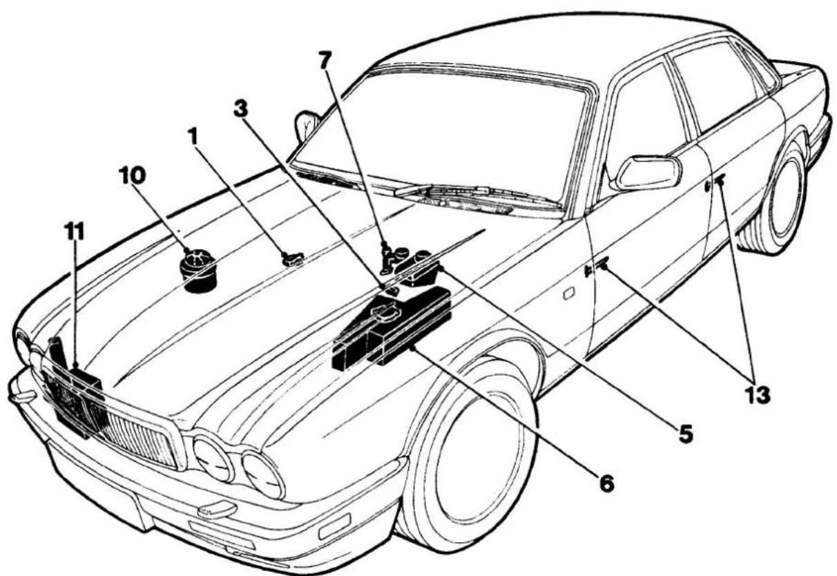

J10-054
- Engine oil - refill
- Engine oil-drain
- Transmission fluid - refill
- Transmission fluid-drain
- Brake fluid - refill
- Engine coolant - refill
-
Clutch fluid-refill
-
Final drive oil-refill
- Final drive oil-drain
- PAS fluid - refill
- Windshield wash reservoir - refill
- Axle shaft UJs - grease
- Door check-arm - grease
Fig. 1 Fluids and Lubricants Service Points- 6 Cylinder Vehicles
A2


J10-055
- Engine oil - refill
- Engine oil - drain
- Transmission fluid - refill
- Transmission fluid - drain
- Brake fluid - refill
-
Engine coolant - refill
-
Final drive oil - refill
- Final drive oil - drain
9.. PAS fluid - refill
10.. Windshield wash reservoir - refill - Axle shaft UJs - grease
- Door check-arm - grease
Fig. 1 Fluids and Lubricants Service Points - 12 Cylinder Vehicles
SERVICE SCHEDULE - UK, EUROPE, ROW
3.2 Liter, 4.0 Liter, 4.0 Liter SC and 6.0 Liter
A2
| Item | Service intervals | Miles (X1000) | |||||
| 10 | 20 | 30 | 40 | 50 | 60 | ||
| 1 | Renew engine oil and filter | X | X | X | X | X | X |
| 2 | Renew transmission fluid and filter | X | X | ||||
| 3 | Renew manual transmission oil | X | X | ||||
| 4 | Renew brake fluid (two years) | X | X | ||||
| 5 | Renew coolant and check specific gravity | X | |||||
| 6 | Renew air cleaner element / s | X | X | X | |||
| 7 | Renew air cleaner element (supercharged) | X | X | X | X | X | X |
| 8 | Renew fuel filter | X | |||||
| 9 | Renew spark plugs (see note) | X | X | X | |||
| 10 | Renew spark plugs (Sweden only) (see note) | X | X | ||||
| 11 | Renew drive belts | X | |||||
| 12 | Check / adjust drive belt tensions | X | |||||
| 13 | Renew wiper blade and clean windshield with Jaguar Screen Clean Paste | X | X | X | X | X | X |
| 14 | Check / adjust parking brake shoes | X | |||||
| 15 | Inspect brake pads for wear (rotor condition on pad change) | X | X | X | X | X | X |
| 16 | Grease axle shaft universal joints | X | X | X | X | X | X |
| 17 | Check front hub end–float | X | X | ||||
| 18 | Clean and adjust front hub bearings | X | |||||
| 19 | Check tire pressures, tread depth, general condition, signs of uneven wear and suitability (including spare) | X | X | X | X | X | X |
| 20 | Check / top up automatic transmission fluid | X | X | X | X | ||
| 21 | Check / top up brake fluid reservoir | X | X | X | X | X | X |
| 22 | Check / top up clutch fluid reservoir | X | X | X | X | X | X |
| 23 | Check / top up cooling system and check specific gravity | X | X | X | X | X | X |
| 24 | Check / top up windshield / power wash reservoir | X | X | X | X | X | X |
| 25 | Check / top up manual transmission oil | X | X | X | X | ||
| 26 | Check / top up final drive oil | X | X | X | X | X | X |
| 27 | Check / top up PAS fluid | X | X | X | X | X | X |
| 28 | Check exhaust system for leakage and security | X | X | X | X | X | X |
| 29 | Check for oil leaks – engine | X | X | X | X | X | X |
| 30 | Check for oil leaks – automatic transmission | X | X | X | X | X | X |
| 31 | Check for oil leaks – manual transmission | X | X | X | X | X | X |
| 32 | Check for oil leaks – final drive | X | X | X | X | X | X |
| 33 | Check for fuel leaks | X | X | X | X | X | X |
| 34 | Check all suspension dampers for fluid leaks | X | X | X | X | X | X |
Note: This note only applies to V12 engines.
When renewing spark plugs, apply silicon grease (TBA) to the spark plug and coil terminals of the ignition cable. This will ensure that the terminal covers remain supple throughout their service life, thus maintaining a good contact and preventing HT leakage.
A2
| Item | Service intervals Miles | (X1000) | |||||
| 10 | 20 | 30 | 40 | 50 | 60 | ||
| 35 | Check power steering system for leaks and hydraulic pipes/ unions for chafing/ corrosion | X | X | X | X | X | X |
| 36 | Check Cooling / heating system for leaks / security | X | X | X | X X | X | |
| 37 | Check visually hydraulic hoses / pipes / unions for leaks / chafing / cracks / corrosion | X | X | X | X | X | X |
| 38 | Check condition of steering rack joint covers | X | X | X | X | X | X |
| 39 | Check speed control vacuum hoses for security and general condition | X | X | X | X | X | X |
| 40 | Grease door check-arm side edges | X | X X | ||||
| 41 | Check parking brake cable adjustment | X | X | X X | X | X | |
| 42 | Clean out radiator matrix and condenser (where fitted) to remove dirt accumulation | X | X | X | |||
| 43 | Clean antenna mast | X | X | X X | X | X | |
| 44 | Carry out road / roller test | X | X | X | X | X | X |

SERVICE SCHEDULE, USA / CANADA
4.0 Liter, 4.0 Liter SC and 6.0 Liter
A2
| Item | Service intervals | Miles (X 1000) | |||||||
| 7.5 | 15 | 22.5 | 30 | 37.5 | 45 | 52.5 | 60 | ||
| 1 | Renew engine oil and filter | X | X | X | X | X | X | X | X |
| 2 | Renew transmission fluid and filter | X | X | ||||||
| 3 | Renew brake fluid (two years) | X | X | ||||||
| 4 | Renew coolant (four years) and check specific gravity | X | |||||||
| 5 | Renew air cleaner element / s | X | X | ||||||
| 6 | Renew air cleaner element / s (SC only) | X | X | X | X | ||||
| 7 | Renew SC unit drive belt (SC only) | X | X | ||||||
| 8 | Check Adjust SC unit drive belt tension (SC only) | X | X | X | X | X | X | ||
| 9 | Renew drive belts (not SC) | X | |||||||
| 10 | Check/ adjust drive belt tensions (not SC) | X | |||||||
| 11 | Renew fuel filter | X | |||||||
| 12 | Renew spark plugs (see note) | X | X | ||||||
| 13 | Renew wiper blade and clean windshield with Jaguar Screen Clean Paste | X | X | X | X | X | X | X | X |
| 14 | Check/ adjust parking brake shoes | X | |||||||
| 15 | Inspect brake pads for wear (rotor condition on pad change) | X | X | X | X | X | X | X | X |
| 16 | Grease axle shaft universal joints | X | X | X | X | X | X | X | X |
| 17 | Check front hub end float | X | |||||||
| 18 | Clean and adjust front hub bearings | X | |||||||
| 19 | Check tire pressures, tread depth, general condition, signs of uneven wear and suitability (including spare) | X | X | X | X | X | X | X | X |
| 20 | Check/ top up automatic transmission fluid | X | X | X | X | X | X | ||
| 21 | Check/ top up brake fluid reservoir | X | X | X | X | X | X | X | X |
| 22 | Check/ top up cooling system and check specific gravity | X | X | X | X | X | X | X | |
| 23 | Check/ top up windshield / power wash reservoir | X | X | X | X | X | X | X | X |
| 24 | Check/ top up final drive oil | X | X | X | X | X | X | X | X |
| 25 | Check/ top up PAS fluid | X | X | X | X | X | X | X | X |
| 26 | Check exhaust system for leakage and security | X | X | X | X | X | X | X | X |
| 27 | Check for oil leaks- engine | X | X | X | X | X | X | X | X |
| 28 | Check for oil leaks- automatic transmission | X | X | X | X | X | X | X | X |
| 29 | Check for oil leaks- final drive | X | X | X | X | X | X | X | X |
| 30 | Check for fuel leaks | X | X | X | X | X | X | X | X |
| 31 | Check all suspension dampers for fluid leaks | X | X | X | X | X | X | X | X |
Note: This note only applies to V12 engines.
When renewing spark plugs, apply silicon grease (TBA) to the spark plug and coil terminals of the ignition cable. This will ensure that the terminal covers remain supple throughout their service life, thus maintaining a good contact and preventing HT leakage.


| Item | Service intervals | Miles (X 1000) | |||||||
| 7.5 | 15 | 22.5 | 30 | 37.5 | 45 | 52.5 | 60 | ||
| 32 | Check power steering system for leaks and hydraulic pipes/ unions for chafing/corrosion | X | X | X | X | X | X | X | X |
| 33 | Check Cooling/ heating system for leaks/ security | X | X | X | X | X | X | X | X |
| 34 | Check visually hydraulic hoses/ pipes/ unions for leaks/ chafing/ cracks/ corrosion | X | X | X | X | X | X | X | X |
| 35 | Check condition of steering rack joint covers | X | X | X | X | X | X | X | X |
| 36 | Check speed control vacuum hoses for security and general condition | X | X | X | X | X | X | X | X |
| 37 | Grease door check-arm side edges | X | X | X | X | ||||
| 38 | Check parking brake cable adjustment | X | X | X | X | X | X | X | X |
| 39 | Clean out radiator t i j l ( I fitt j ) to remove dirt accumulation | X | X X | X | |||||
| 40 | Clean t t | X | X | X | X | X | X | X | X |
| 41 | , out road' ll t t | X | X | X | X | X | X X | X | |


SECTION CONTENTS
Subsection Title
SRO
Page
i ...... Preliminary Page ...... i
A3.1 Safety Precautions 1
A3.1.1 Safety Precautions. Used Engine Oils 1
A3.1.2 Safety Precautions. Health Protection Precautions 1
A3.1.3 Safety Precautions. Environmental Protection Precautions 1
A3.2 ...... General Fitting Instructions ...... 2
A3.2.1 General Fitting Instructions. Precautions Against Damage To The Vehicle 2
A3.2.2 ...... General Fitting Instructions. Preparation ...... 2
A3.2.3 General Fitting Instructions. Dismantling 2
A3.2.4 General Fitting Instructions. Inspection 2
A3.2.5 General Fitting Instructions. Ball And Roller Bearings 3
A3.2.6 General Fitting Instructions. Oil Seals 3
A3.2.7 ...... General Fitting Instructions. Joints And Joint Faces ...... 4
A3.2.8 General Fitting instructions. Hydraulic Flexible Pipes And Hoses 4
A3.2.9 General Fitting Instructions. Metric Bolt identification 4
A3.2.10 ...... General Fitting instructions. Metric Nut Identification ...... 4
A3.2.11 ...... General Fitting Instructions. Hydraulic Fittings—Metrification ...... 5
A3.2.12 ...... General Fitting Instructions. Keys And Keyways ...... 6
A3.2.13 ...... General Fitting Instructions. Split Pins ...... 6
A3.2.14 General Fitting instructions. Tab Washers 6
A3.2.15 ...... General Fitting instructions. Special Fixings ...... 6
A3.2.16 ...... General Fitting Instructions. Nuts ...... 7
A3.2.17 ...... General Fitting Instructions. Locking Wire ...... 7
A3.2.18 ...... General Fitting Instructions. Screw Threads ...... 7
A3.2.19 ...... General Fitting Instructions. Unified Thread Identification - Bolts ...... 7
A3.2.20 ...... General Fitting Instructions. Unified Thread Identification - Nuts ...... 7
A3.2.21 ...... General Fitting Instructions. Unified Thread Identification - Studs. Brake Rods. etc.... 7
A3.3 Taper Roller Bearings - Fault Diagnosis 8


A3.1 SAFETY PRECAUTIONS
Whenever possible, use a ramp or pit whilst working beneath a car, in preference to jacking. Position chocks at the wheels as well as applying the handbrake. Never rely on a jack alone to support a car. Use axle stands, or blocks carefully placed at the jacking points, to provide rigid location. Check that any lifting equipment used has adequate capacity and is fully serviceable. Ensure that a suitable form of fire extinguisher is conveniently located. When using electrical tools and equipment, inspect the power lead for damage and check that it is properly earthed. Disconnect the earth (grounded) terminal of the car battery. Do not disconnect any pipes of the air conditioning refrigerationsystem unless you are trained and instructed to do so. A refrigerant is used which can cause blindness if allowed to come into contact with the eyes. Ensure that adequate ventilation is provided when volatile degreasing agents are being used.

WARNING: FUME EXTRACTION EQUIPMENT MUST BE IN OPERATION WHEN SOLVENTS ARE USED E.G. TRICHLOROETHANE, WHITE SPIRIT, SBP3, METHYLENE CHLORIDE, PERCHLORETHYLENE. DO NOT SMOKE IN THE VICINITY OF VOLATILE DEGREASING AGENTS.
Adhere strictly to handling and safety instructions given on containers and labels. Keep oils and solvents away from naked flames and other sources of ignition. Do not apply heat in an attempt to free seized nuts or fittings; as well as causing damage to protective coatings, there is a risk of damage from stray heat to electronic equipment and brake lines. Do not leave tools, equipment, spilt oil etc. around or on work area. Wear protective overalls and use barrier cream when necessary.

A3.1.1 Used Engine Oils
Prolonged and repeated contact with mineral oil will result in the removal of natural oils from the skin, leading to dryness, irritation and dermatitis. In addition, used engine oil contains potentially harmful contaminants which may cause skin cancer. Washing facilities and adequate means of skin protection should be provided.
A3.1.2 Health Protection Precautions
- Avoid prolonged and repeated contact with oil; particularly used engine oils.
- Wear protective clothing, including impervious gloves where practicable
- Do not put oily rags in pockets.
- Avoid contaminating clothes, particularly underwear, with oil.
- Overalls must be cleaned regularly. Discard unwashable clothing and footwear which is oil impregnated.
- First Aid treatment should be obtained immediately for open cuts or wounds.
Use barrier creams, applying before each work period, to enable easier removal of dirty oil / grease from the skin. - Wash with soap and water to ensure that all oil is removed (skin cleaner and a nail brush will help). The use of preparations containing lanolin will help to replace the natural skin oils which have been removed.
Do not use petrol, kerosene, gas oil, thinners or solvents for washing skin. - If skin disorders develop, obtain medical advice immediately.
Where practicable, degrease components prior to handling.
Where there is a risk of fluids coming into contact with the eyes, eye protection should be worn, for example, goggles or a face shield. An eye wash facility should be provided.
A3.1.3 Environmental Protection Precautions
It is illegal to pour used oil on to the ground, down sewers or drains, or into water courses. The burning of used engine oil in small space heaters or boilers is not recommended unless emission control equipment is fitted. Dispose of used oil through authorized waste disposal contractors, to licensed waste disposalsites or to the waste oil reclamationtrade. Ifin doubt, contact the Local Authority for advice on disposal facilities.

A3.2 GENERAL FITTING INSTRUCTIONS
A3.2.1 Precautions Against Damage To The Vehicle

Always fit covers to protect the wings before commencing work in the engine compartment. Cover the seats and carpets, wear clean overalls and wash hands or wear gloves before working inside the car. Avoid spilling hydraulic fluid, anti-freeze or battery acid on the paintwork. In the event of spillage, wash off with water immediately. Use polythene sheets in the boot to protect carpets. Always use the recommended service tool, or a satisfactory equivalent, where specified. Protect temporarily exposed screw threads by replacing nuts or fitting caps.
A3.2.2 Preparation
Before disassembly, clean the surrounding area as thoroughly as possible. When components have been removed, blank off any exposed openings using greaseproof paper and masking tape. Immediately seal fuel, oil and hydraulic lines when separated, using plastic caps or plugs, to prevent loss of fluid and the entry of dirt. Close the open ends of oilways, exposed by component removal, with tapered hardwood plugs or readily visible plastic plugs. Immediately a component is removed, place it in a suitable container; use a separate container for each component and its associated parts. Before dismantling a component, clean it thoroughly with a recommended cleaning agent: check that the agent will not damage any of the materials within the component. Clean the bench and obtain marking materials, labels, containers and locking wire before dismantling a component.
A3.2.3 Dismantling
Observe scrupulous cleanliness when dismantling components, particularly when parts of the brake, fuel or hydraulic system are being worked on. A particle of dirt or a fragment of cloth could cause a dangerous malfunction if trapped in these systems. Clean all tapped holes, crevices, oilways and fluid passages with compressed air.
WARNING: DO NOT PERMIT COMPRESSED AIR TO ENTER AN OPEN WOUND. ALWAYS USE EVE PROTECTION WHEN USING COMPRESSED AIR.
Ensure that any 'O'-rings used for sealing are correctly refitted or renewed if disturbed. Mark mating parts to ensure that they are replaced as dismantled. Whenever possible use marking materials which avoid the possibilities of causing distortion or the initiation of cracks, which could occur if acenter punch or scriber were used. Wire together mating parts where necessary to prevent accidental interchange (e.g roller bearing components). Tie labels onto all parts to be renewed and to parts requiring further inspection before being passed for reassembly.
Place labelled parts and other parts for rebuild in separate containers.
Do not discard a part which is due for renewal until it has been compared with the new part, to ensure that the correct part has been obtained.
A3.2.4 Inspection
Before inspecting a component for wear or performing a dimensional check, ensure that it is absolutely clean; a slight smear of grease can conceal an incipient failure. When a component is to be checked dimensionally against figures quoted for it, use the correct equipment (surface plates, micrometers, dial gauges etc.) in serviceable condition. The use of makeshift equipment can be dangerous. Reject a component if its dimensions are outside the limits quoted, or if damage is apparent. A part may be refitted if its critical dimension is exactly to the limit size and it is otherwise satisfactory. Use Plastigauge 12 Type PG-1 for checking bearing surface clearance e.g. big end bearing shell to crank journal. Instructions for the use of Plastigauge and a scale giving bearing clearances in steps of 0,0025 mm (0.0001 in) are supplied with the package.
A3.2.5 Ball And Roller Bearings
CAUTION: Never replace a ball or roller bearing without first ensuring that it is in as-new condition.
Remove all traces of lubricant from the bearing by washing it in petrol or a suitable degreaser. Maintain absolute cleanliness throughout the operations. Inspectvisually for markings of any form on rolling elements, bearing tracks, outer surface of outer rings or inner surface of inner rings. Reject any bearings found to be marked, since any markings in these areas indicates the onset of wear.
Hold the inner race between the fingers and thumb of one hand, spin the outer race and check that it revolves absolutely smoothly. Rotate the outer ring with a reciprocating motion, while holding the inner ring; feel for any obstruction to rotation and reject the bearing if the action is not perfectly smooth. Lubricate the bearing generously with lubricant appropriate to the installation. Inspect the shaft and bearing housing for discolouration or other marking which may suggest that movement hastaken place between the bearing and bearing seat. If markings are found, use Loctitewhen installing the replacement bearing.

Ensure that the shaft and housing are clean and free from burrs before fitting the bearing. If one bearing of a pair shows an imperfection, it is generally advisable to renew both bearings: an exception could be made only if the bearings had covered a low mileage and it could be established that damage was confined to the one bearing.
In the case of bearings which are lubricated with grease (e.g. hub bearings) the space between the bearings should be smeared with a recommended grade of grease, and the bearings and seal should be re-packed. When fitting the bearing to the shaft, apply force only to the inner ring of bearing (Fig. 1A). When fitting the bearing to the housing, apply force only to outer ring (Fig. 1B).
Always mark components of separable bearings (e.g taper roller bearings) when dismantling, to ensure correct reassembly. Neverfit a new inner roller assembly toa used outer track.
A3.2.6 Oil Seals
Always fit new oil seals when rebuilding an assembly. Examinethe seal before fitting to ensure that it is clean and undamaged. Smear sealing lips with clean grease, pack dust excluder seals with grease and pack grease into the cavity between the sealing lips of duplex seals. Ensure that the seal spring, if provided, is correctly fitted.

Place the lip of the seal towards the fluid to be sealed and slide it into position on the shaft, using a fitting sleeve (Fig. 2) when possible to protect the sealing lip from damage by threads, splines or sharp edges on the end of the shaft. If a fitting sleeve is not available, use plastictube or adhesive tape to prevent damage to the sealing lip.
Grease the outsidediameter of the seal, place it square to the housing recess and press it into position, using great care and, where available, a seal installer (Fig. 3) to ensure that the seal does not tilt. In some cases it may be preferable to fit the seal to the housing before fitting it to the shaft. Never let the weight of an unsupported shaft rest in a seal. If the correct servicetool is not available, use a piece of tube which is approximately 0.4 mm (0.015 in) smaller than the outside diameter of the seal. Usea press to install the seal or use a hammer VERY GENTLY on the tubular drift if a press is unsuitable or not available.
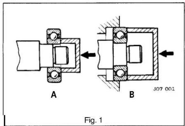
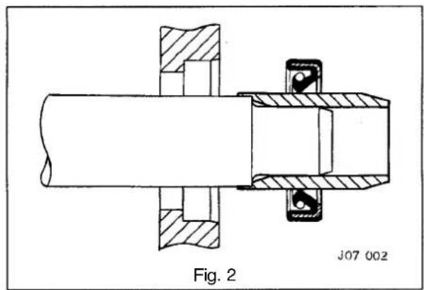


Pressordriftheseal into the full depth of the housing if the housing is shouldered, or flush with the face of the housing where no shoulder is provided.
Note: Careless fitting of oil seals, which can result in damage to the seal and sealing surfaces, accounts for most cases of failure of seals. Care in fitting is essential if good results are to be obtained.
A3.2.7 joints And joint Faces
Remove all traces of old jointing materials prior to reassembly. Inspect joint faces for scratches or burrs and remove with a fine file or oilstone; do not allow swarf or dirt to entertapped holes or enclosed parts. Blow out any pipes, channels or crevices with compressed air, refitting or renewing any 0-rings or seals which have been displaced by the compressed air.
Always use the specified gaskets. Use jointing compound only when recommended, otherwise fit joints dry. When jointing compound is used, apply in a thin film to metal surfaces; take great care to prevent it from entering oilways, pipes or blind tapped holes.
A3.2.8 Hydraulic Flexible Pipes And Hoses
Before removing a hose from the brake or power steering systems, thoroughly clean the end fittings and the area surrounding them. Obtain blanking caps before detaching hose fittings, so that ports can be covered to excluded dirt. Clean the hose externally and blow through with compressed air. Examine the hose carefully for cracks, separation of plies, security of end fittings and external damage. Reject any hose found to be faulty. When refitting the hose, ensure that no unnecessary bends are introduced and that the hose is not twisted before or during tightening of union nuts.
Do not store hydraulic fluid in an unsealed container because it will absorb water. Fluid in this condition would be dangerous to use due to a lowering of its boiling point. Do not allow hydraulic fluid to be contaminated with mineral oil, or use a container which has previously contained mineral oil.
Do not re-use fluid bled from the system. Always use clean brake fluid, or a recommended alternative, to clean the hydraulic components. Fit a blanking cap to the hydraulic union and a plug to its mating socket, after removal from the vehicle, to prevent ingress of dirt. Absolute cleanliness must be observed with hydraulic components at all times. After any work has been performed on hydraulicsystems, inspect carefully for leaks underneath the car while a second operator applies maximum pressure to the brakes (with the engine running) and operates the steering.
A3.2.9 MetricBolt Identification
An ISO metric bolt or screw, made of steel and larger than 6mm in diameter can be identified by the symbols ISOM or M embossed on top of the head (Fig. 1). In addition to marks to identify the manufacturer, the head is also marked with symbols to indicate the strength grade eg 8.8, 10.9, 12.9 or 14.9. The first figure gives the minimum strength of the bolt material in tens of kgf / mm 2 . Zinc plated ISO metric bolts and nuts are chromate passivated and coloured greenish-khaki to gold-bronze.
A3.2.10 Metric Nut Identification
A nut with anISO metricthread is marked on one face1 Fig. 2) or on one of the flats (2 Fig. 2) of the hexagon with the strength grade symbol 8, 12 or 14. Some nuts with a strength4,5 or 6 are also marked and some have the metric symbol M on theflat which is oppositeto the strength grade marking.
Aclockfacesystem is used as an alternative method of indicating the strength grade(3 Fig. 2). The external chamfers or a face of the nut is marked in a position relative to the appropriate hour mark on a clock face to indicate the strength grade. A dot is used to locate the 12 o'clock position and a dash to indicate the strength grade. If the grade is above 12, two dots identify the 12 o'clock position.


A3.2.11 Hydraulic Fittings - Metrification
Metric fastenings are being used increasingly in motor vehicle manufacture, but the use of some UNF threaded parts must be expected. Technicians must take note of warnings that dangers exist while UNF and metricthreaded hydraulic parts continue to be used together.
UNF pipe nuts should not be fitted into metric parts, nor vice-versa. Experience indicates that it is not safe to rely upon the difference in thread size. Providing permanent identification of metric parts is not easy, but recognition has been assisted by the following means:
All metric pipe nuts, hose ends, unions and bleedscrews are coloured black. The hexagon area of pipe nuts is indented with the letter 'M'. Metric and UNF pipe nuts are slightly different in shape.
Note: In the illustrations on this page, 'A' indicates the metrictype and 'B'the UNF type. The metricfemale nut is always used with a trumpet flared pipe and the metric male nut is always used with a convex flared pipe (Fig. 1).


Metric ports in brake cylinders and calipers have no counterbores; however, a few cylinders with UNF threads also have no counterbore. Therefore, all ports with counterbores are UNF, but ports not counterbored are most likely to be metric (Fig. 2).
The colour of the protective plugs fitted to cylinder ports indicate the size and the type of the threads, but the primary function of the plugs is to protect the cylinder from contamination and is not intended as a positive means of identification. As an indication, the plug colours and thread sizes are:
| Colour | Size | Colour | Size |
| Red | 3/8 in. x 24 UNF | Black | 10 x 1,0 mm |
| Green | 7/16 in. x 20 UNF | Grey | 12 x 1,0 mm |
| Yellow | 1/2 in. x 20 UNF | Brown | 14 x 1,5 mm |
| Pink | 5/8 in. x 18 UNF |


Note: InFig. 1 and Fig. 2, this page, 'A' indicates the metric type and 'B' the UNF type.
Hose ends differ slightly between metric and UNF (Fig. 1). Gaskets are not used with metric hoses; the metric hose fitting seals against the bottom of the port and consequently there is a gap between the hexagonalface of the hosefitting and the cylinder (Fig.2A). The UNF hosefitting is sealed on the brakecylinder or caliperface by a copper gasket (Fig.2B).
Pipe sizes (outside diameter) for UNF are 3/16 in., 1/4 in. and 5/16 in. Metric pipe sizes are 4,75 mm, 6mm and 8 mm. The 4,75 mm pipe is exactly the same diameter as 3/16 in. pipe. The 6 mm pipe is 0.014 in. smaller than 1/4 in. pipe. The 8 mm pipe is 0.002 in. larger than 5/16 in. pipe.
Convex flares for metric brake pipes have a different form thanthoseon UNFbrake pipes. When making pipesfor metric equipment, metric pipe flaring tools must be used.
The greatest danger lies with the confusion of 10 mm and 3/8 in. UNF pipe nuts used for 3/16 in. (or 4,75 mm) pipe. The 3/8 in. UNF pipe nut or hose can be screwed into a 10 mm port, but is very slack and easily stripped. The thread engagement is very weak and cannot provide an adequate seal. The opposite condition, a 10 mm nut in a 3/8 in. port, will cause difficulty during fitting. The 10 mm nut will screw infor one or two turns and then seize. It has a crossed thread 'feel' and it is impossible to force the nut far enough to seal the pipe. With female pipenuts the position is reversed. The other combinations are so different that there is no danger of confusion.
A3.2.12 Keys And Keyways
Remove burrs from the edges of keyways with a finefile and clean thoroughly before attempting to refit the key. Clean and inspect the key closely. Keys are suitable for refitting only if no indentations exist (which would indicate the onset of wear).
A3.2.13 Split Pins
Fit new split pins throughout when replacing any unit. Always fit split pins where split pins were originally used. Do not substitute spring washers for split pins. All split pins should be fitted as shown (Fig. 3) unless otherwise stated.
A3.2.14 Tab Washers
Fit new tab washers in all places where they were used originally. Never refit a used tab washer. Ensure that the new tab washer is of the same design as that which was removed.
A3.2.15 Special Fixings
Bolts with a blue coating applied to the thread are used in various areas of the vehicle. Should any of these bolts be removed, they MUST be replaced with NEW bolts of the same type. Nyloc nuts are used in various areas of the vehicle. If removed these MUST be replaced with NEW nuts of the same type.
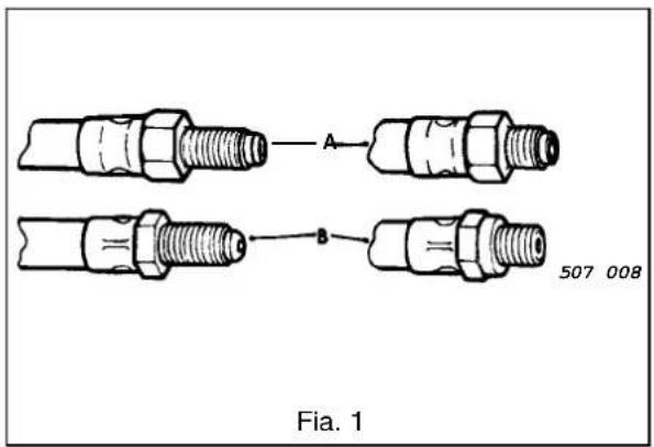

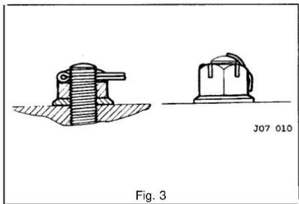

A3.2.16 Nuts
When tightening a slotted or castellated nut, never slacken it in order to insert the split pin or locking wire, but tighten it to align the next slot. The exception is in those recommended cases where slackening the nut forms part of an adjustment e.g. bearing endfloat or preload adjustment. If difficulty is experienced, alternative washers or nuts should be selected, or a washer of a different thickness used. Where self-locking nuts have been removed, replace them with new ones.
A3
A3.2.17 Locking Wire
Fit new locking wire of the correct type to the assemblies incorporating it. Arrange the wire so that its tension tends to tighten the bolt heads, or nuts, to which it is fitted.
A3.2.18 Screw Threads
Metricthreads toISO standards and UNF threads are used. See belowforthread identification. Fixingswith damaged threads must always be discarded. Cleaning the threads with a die or tap impairs the strength and closeness of fit and is not recommended. Always ensure that replacementbolts are of equal strength to those removed. Do not allow oil, grease or jointing compound to enter blind threaded holes because the hydraulic action which would be generated when screwing in the bolt or stud could split the housing. Oil the thread lightly before tightening to ensure a free running thread, except in the case of self locking nuts. Always tighten a nut or bolt to the recommended torque figure. Damagedor corrodedthreads will affect the torque reading. To check or retighten a bolt or screw to a specified torque figure, first slacken by a quarter of a turn, then retighten to the correct figure.

A3.2.19 Unified Thread Identification- Bolts
A circular recess is stamped in the upper surface of the bolt head (1 Fig. 1).
A3.2.20 Unified Thread Identification- Nuts
A continuous line of circles is stamped on one of the flats of the hexagon, parallel to the axis of the nut (2 Fig. 1).
A3.2.21 Unified Thread Identification - Studs, Brake Rods, etc.
The component is reduced to the core diameter for a short length at its extremity (3 Fig. 1).
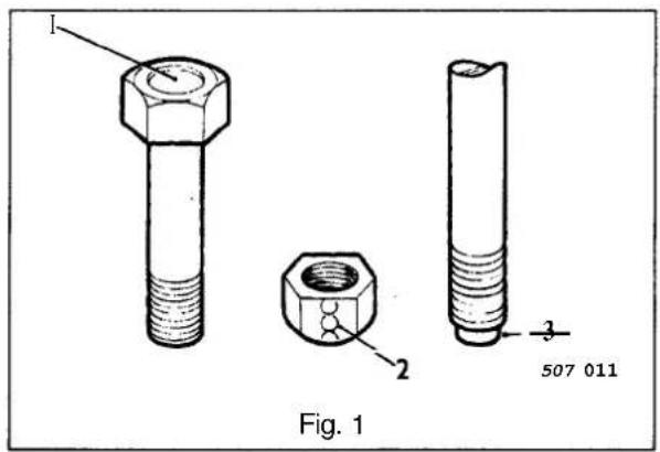


A3.3 TAPERROLLER BEARINGS, FAULT DIAGNOSIS
Fault
Bent cage.
Cause
Improper handling or use of tool.
Remedy
Renew the bearing.
Fault
Bent cage.
Cause
Improper handling or use of tool.
Remedy
Renew the bearing.
Fault
Galling.
Cause
Marks on roller ends due to overheating, lubricant failure or overloading.
Remedy
Renew the bearing. Check the seals and ensure that the bearing is properly lubricated.
Fault
Step wear.
Cause
Wear on the roller ends caused by fine abrasives.
Remedy
Clean all components and housings. Check the seals and bearings, and renew if leaking, rough or noisy.
Fault
Fretting.
Cause
Corrosion caused by small movement of components with no lubrication.
Remedy
Renew the bearing. Check the seals for leakage and ensure that there is adequate lubrication.

J51 050


J51 051


J51 052


J51 053

J51 063

Fault
Misalignment.
Cause
Outer track misalignment usually due to a foreign body under the track.
Remedy
Clean all components and replace or renew the bearing and ensure that the new track is correctly seated.

A3
Fault
Indentations.
Cause
Surfaces are depressed on the race and the track caused by hard particles of foreign material.
Remedy
Clean all components and housings. Check the seals and bearings, and renew if leaking, rough or noisy.

Fault
Flaking.
Cause
Flaking of the surface material due to fatigue.
Remedy
Renew the bearing and clean all related components.


Fault
Indentations.
Cause
Surface indentations in the track caused by rollers either vibrating or impact loading while the bearing is not rotating.
Remedy
Renew the bearingifrough or noisy.

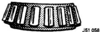
Fault
Cage wear.
Cause
Wear around the outside diameter of the cage and roller pockets caused by poor lubrication and abrasive material.
Remedy
Renew the bearings and check the condition of the seals.


Fault
Roller wear.
Cause
Marks on track and rollers caused by fine abrasives.
Remedy
Clean all components and housings. Check the seals and bearings, and renew if leaking, rough or noisy.
Fault
Cracked race.
Cause
Race cracked due to incorrect fitting to shaft, tipping or poor seating.
Remedy
Renew the bearing and check the condition of the seals.
Fault
Discolouration.
Cause
Discolouration ranging from black to light brown caused by moisture or incorrect use of lubricants.
Remedy
Re-use bearingsif stains can be removed by light polishing or if no evidence of overheating is apparent. Check the seals and other component part condition. Renew as necessary.
Fault
Discolouration.
Cause
Heat discolouration ranging from blue to faint yellow, resulting from overload or incorrect lubricant. As excessive heat can cause softening of tracks and rollers, check by drawing a finefile over a softened area. If faulty, the file will grab and cut metal. If still hard, the file will skid over the surface without removing any material.
Remedy
Renew the bearings and seals if any heat damage is evident.


Fault
Seizure.
Cause
Seizure caused by lack of lubrication, excessive loads or the ingress of foreign matter.
Remedy
Renew the bearings. Check the seals for wear and ensure that there is adequate lubrication.

J51 066
A3
Fault
Etching.
Cause
The bearing surfaces are grey or greyish black, with the rollers and track material being etched away. This is usually related to uneven spacing of the rollers.
Remedy
Renew the bearings. Check the seals for wear and ensure that there is adequate lubrication.

Fault
Rotating track and inner race material removal.
Cause
Removal of material due to slippage. This can be caused by poor fit, incorrect lubrication, overheating, overloading and poor assembly.
Remedy
Renewthe bearings and clean all related parts. Check the fit and ensure the replacement bearings are the correct type. Renew the shaft or housing if damaged.


SECTION CONTENTS
Sub-Section Title SRO Page
| i Toiii | Preliminary Pages | i Toiii |
| A4.1 | Body Repair, Introduction | 1 |
| A4.1.1 | Health And Safety | 1 |
| A4.1.2 | Notification Of Hazards | 2 |
| A4.1.3 | Potential Risks | 3 |
| A4.1.3.1 | Potential Risks. Paint | 3 |
| A4.1.3.2 | Potential Risks. Applied Heat (Welding) | 3 |
| A4.1.3.3 | Potential Risks. Metal Repair | 3 |
| A4.1.4 | Precautions | 3 |
| A4.1.4.1 | Precautions. Paint | 3 |
| A4.1.4.2 | Precautions. Applied Heat | 3 |
| A4.1.4.3 | Precautions. Metal Repair | 3 |
| A4.1.5 | General Repair Notes | 4 |
| A4.1.5.1 | Welding & Gas Processes. Special Notes | 4 |
| A4.1.6 | Plastics. Explanatory Notes | 5 |
| A4.1.6.1 | Plastic Component & Trim Materials.- Table | 5 |
| A4.1.6.2 | Plastics. Handling Notes | 5 |
| A4.1.6.3 | Recycled Materials | 5 |
| A4.1.6.4 | Plastics. Component Location& Type- External Illustration | 6 |
| A4.1.6.5 | Plastics. Component Location& Type- Internal Illustration | 7 |
| A4.1.6.6 | Plastics. Component Location& Type- Underhood, Illustration | 8 |
| A4.2 | Body Structure | 9 |
| A4.2.1 | Body Structure. Introduction | 9 |
| A4.2.1.1 | Body Structure. Constructional Steel Classification - Table | 9 |
| A4.2.2 | Body Alignment | 9 |
| A4.2.2.1 | Body Alignment. Datum Location | 10 |
| A4.2.2.2 | Body Alignment. Plan View - Key to Illustration | 10 |
| A4.2.2.3 | Body Alignment. Side View - Key to Illustration | 12 |
| A4.2.3 | Zinc Coated Panels | 14 |
| A4.2.3.1 | Zinc Coated Panels. Description | 14 |
| A4.2.3.2 | Zinc Coated Panels. Welding Preparation | 14 |
| A4.2.3.3 | Zinc Coated Panels. Body Fillers | 14 |
| A4.2.3.4 | Zinc Coated Panels. Refinishing | 14 |
| A4.2.4 | Panels -Associated. Renew | 77.10.02 15 |
| A4.2.5 | Surfaces (Old). Prepare | 77.10.03 16 |
| A4.2.5.1 | Surfaces (New). Prepare | 77.10.04 16 |
| A4.2.5.2 | Panels -Align And Weld | 77.10.05 & 06 17 |
| A4.2.6 | Cutting And Welding Symbols | 18 |
| A4.3.1 | Adhesive. Sealers and Body Protection - Approved Systems | 19 |
| A4.3.1.1 | Body Sealing & Preservation Manual - Section Relevance | 19 |
| A4.3.2 | Cavity Wax Injection | 19 |
| A4.3.2.1 | Cavity Wax Injection Points - Front. Illustration | 20 |
| A4.3.2.2 | Cavity Wax Injection Points - Rear, Illustration | 21 |
| A4.3.3 | Underseal. Application Area | 22 |
| A4.3.4 | Insulation Pads. Location | 23 |
| A4.3.5 | Foam Injection | 24 |
| A4.4.1 | Paint Systems - Approved. Table | 25 |
| A4.4.1.1 | General Recommendations (Paint Refinishing Manual) | 25 |
| A4.4.1.2 | Paint Refinishing Manual. Section Relevance | 25 |
| A4.4.2 | 'Black-Out' Areas. Illustration | 26 |
| A4.4.3 | Anti-theft labels | 27 |
| A4.4.3.1 | Anti-theft labels. Original Components | 27 |
| A4.4.3.2 | Anti-theft Labels. Replacement Components | 27 |
| A4.4.3.3 | Anti-theft Labels. Procurement | 27 |
| A4.4.3.4 | Anti-theft Labels. Location - Front | 28 |
| A4.4.3.5 | Anti-theft Labels. Location - Rear | 29 |
| A4.4.3.6 | Anti-theft Labels. Location - Power unit & Transmission | 30 |
| A4.4.3.7 | Anti-theft Labels. Fitting Process | 31 |


Sub-Section Title
SRO
Page
A4.4.4 Underhood Labels. Location& Type 32
A4.4.5 Stonechip Protection Area 33
A4.5 Glazing 34
A4.5.1 Glazing. Special Notes 34
A4.5.1.1 Glass And Body Preparation 34
A4.5.1.2 Glazing Adhesive Application Temperature 34
A4.5.1.3 Glazing Adhesive Application 34
A4.5.1.4 Glazing Adhesive Curing 34
A4.6.1 Bumpers 35
A4.6.1.1 ...... Bumpers. Major Components ...... 35
A4.6.1.2 ...... Bumpers. Features.... 35
A4.6.1.3 Bumpers, Service Procedures 37
A4.6.1.4 Bumpers. Fitted Condition - Front 37
A4.6.1.5 ...... Bumpers. Fitted Condition -Rear ...... 38
A4.6.2 Bumpers, Cover Damage 39
A4.6.2.1 ...... Bumpers. Damage Assessment ...... 39
A4.6.2.2 Bumpers. Repair Materials 39
A4.6.3 Bumpers. Refinishing 40
A4.6.3.1 Bumpers. Refinishing-Original 40
A4.6.3.2 ...... Bumpers. Refinishing- New ...... 40
A4.6.3.3 Bumpers. Refinishing - All 40
A4.6.4 Bumpers. Replacement Covers 40
A4.6.5 .... Recycled Materials. General Note .... 40
A4.6.6 Body-side Moulding 41
A4.6.6.1 Body-side Moulding, Introduction 41
A4.6.6.2 Body-side Moulding. Fitted Condition- Illustration 41
A4.6.6.3 Body-side Moulding. Fitting Process 41
A4.6.7 Finisher, Door Frame – Fitted Condition 42
A4.6.8 Finisher, Roof Drip Rail- Fitted Condition 42
A4.7.1 Body Exterior Clearances & Alignments 43
A4.7.1.1 Body Exterior Clearances & Alignments. Introduction 43
A4.7.1.2 Body Exterior Clearances & Alignments. Criteria – Clearances 43
A4.7.1.3 Body Exterior Clearances & Alignments. Criteria - Alignment 43
A4.7.1.4 Body Exterior Clearances & Alignments. Criteria - Exterior Fitments 43
A4.7.1.5 Body Exterior Clearances & Alignments. Illustrations (Specifications) 43
A4.7.2 Doors 47
A4.7.2.1 Doors, Features 47
A4.7.2.2 .... Doors, Removal .... 47
A4.7.2.3 Doors, Fitting 47
A4.7.2.4 Doors, Alignment 47
A4.7.2.5 .... Door Seals. Table .... 48
A4.7.2.6 Door Seals - Typical Sections. Illustration 48


I. SERVICE TOOLS & EQUIPMENT
| Illustration | Jaguar Number | Description | Notes |
| see text | N/A | Support jig, bumper cover | Locally made |
| not illustrated | N/A | Rear strut height setting tool | Locally made |
| not illustrated | N/A | Guide block to fender setting tool | Locally made |
| not illustrated | N/A | Heated extrusion gun for glazing adhesive | Manufactured by Gurit Essex |
| not illustrated | N/A | Heated cabinet for glazing adhesive | Manufactured by Gurit Essex |
II. TORQUE TIGHTENING SPECIFICATIONS
| Fixing | Tightening Torque (Nm) |
| Bumper – Beam to mounting strut height adjuster | 39 – 50 |
| Bumper – Guide block to fender | 16 – 20 |
| Bumper – Mounting brkt or strut to body | 22 – 28 |
| Door check arm to ‘A’ / ‘C’ pillar | 8.5 |
| Door hinge locking screw | 15 |
| Sliding roof frame to body | 3.5 – 5 |
| Sliding roof outer panel to frame | 3.5 – 5 |
III. SERVICE MATERIALS
| Description | Uses | Notes |
| 3M 5900 FPRM | Bumper substrate repair | See section A4.6 |
| Kent Industries Urepatch | Bumper substrate repair | See section A4.6 |
| Gurit Essex Betaseal 1855 | Glazing adhesive | See section A4.5 |
| Grease | Door check arm | See section A4.7 |
IV. SERVICE DATA
| Application | Specification |
| Wheelbase | 2870 mm |
| Front track (centre of tread to centre of tread) | 1500 mm |
| Rear track (centre of tread to centre of tread) | 1498 mm |

A4


A4.1 BODY REPAIR
Introduction
This section contains information, specifications and procedures for body repair and rectification of the Jaguar sedan range (with standard wheelbase).
All repairs, whether structural or cosmetic, must ensure the continuance of the Paint Surface and Corrosion warranty, where applicable.
Following repair or rectification, the vehicle must be returned to the original manufactured condition with regard to occupant safety, dimensional accuracy, finish and corrosion protection.
Similarly, repaired vehicles must be fully checked, and where appropriate reset, with regard to steering, suspension, restraint and braking systems.
A4
A4.1.1 Health and Safety
(Please Read The Following Notes Carefully)
Where legislation governing working conditions and practises is applicable, you should observe it. Do not forget that you have a duty, to yourself and those around you, to act in a responsible manner in the workplace.
In the United Kingdom the Health and Safety at Work Act (1974) places a duty on employers and employees to ensure, whenever possible, safe working conditions and practices. Wherever a potential hazard is notified to, or identified by the operator, he must employ the correct safety procedures and equipment.
Should a personal injury occur as a result of any workshop activity, seek medical help as soon as possible and do not attempt self-treatment other than by the application of first aid.
With the constant introduction of new materials in the manufacture of vehicles, it is important that potential risks are identified and precautions made known.
WARNING: READ AND UNDERSTAND WORKING PRACTICES CLIMATE CONTROL SYSTEMS, SECTION 14, WITH SPECIAL REFERENCE TO
DO NOT VENT REFRIGERANT DIRECTLY TO ATMOSPHERE, ALWAYS USE JAGUAR APPROVED RECOVERY / RECYCLE / RECHARGE EQUIPMENT.
WEAR SUITABLE EYE AND SKIN PROTECTION.
OBSERVE ALL APPLICABLE SAFETY REQUIREMENTS.


A4.1.2 Notification Of Hazards
Symbols, which convey important information, will be positioned at the beginning of any specific operation or text.
Standard symbols will be used where repairs or service procedures are detailed.
All symbols will conform to standard ANSI 2535.3 (American National Standards Institute).
A4
The surround shape of the symbol will indicate the basis of the message to be conveyed (seetop three elements of Fig. 1)
- The icon depicting the message wibb e within the sur rounding shape.
Once nominated the icon will retain its meaning.
Hazard
Mandatory Action
Information



J77-136
Flammable
Explosion
Poison
Eye protection
Ear protection
Respiratory protection (air-fed)
Respiratory protection (self contained)
Hand protection
Extinguisher







Fig. 1 Symbols
A4.1.3. POTENTIAL RISKS
A4.1.3.1 Paint
Organic solvents, found in paints, may cause damage or severe irritation to liver, kidneys, digestive tracts and respiratory system if inhaled over long periods of time.
Prolonged exposure to isocyanates may cause lung sensitization. Asthma-like symptoms may develop with subsequent exposure to very low concentrations of isocyanates.
Solvent inhalation can cause dizziness or loss of consciousness.
Inhalation of spray dust and sanding debris may cause lung damage.
Splashes of solvents, paint activators and additives can cause damage to the eyes and may cause dermatitis. Peroxide and acid catalysts may cause burns.
A4
A4.1.3.2 Applied Heat (Welding)
There is considerable risk of damage to eyes and skin when welding or flame cutting.
Fire is a serious danger and many materials or fluids within the vehicle are highly flammable.
Toxic and dangerous fumes may be liberated when any of the following are subjected to heat:
- Expanded foam
Corrosion protection
○ Trim and seat materials
○ Paints which contain isocyanates
○ Adhesive and sealing compounds
When heated to a temperature of 300° C, polyurethane-based compounds may liberate small quantities of isocyanate. Many types of nitrogen containing chemicals may be liberated as breakdown products; these chemicals can contain isocyanates, oxides of nitrogen and hydrogen cyanide.
Potentially toxic or asphyxiant fumes and gases are produced by welding, for example; zinc oxide with zinc coated panels, and ozone gas from the MIG process.
A4.1.3.3 Metal Repair
There is considerable risk of damage to eyes, ears and skin when metal cutting, forming, or dressing is being carried out.
Soldering may be hazardous because of heat generated fumes and skin contact with the materials.
A4.1.4. PRECAUTIONS
A4.1.4.1 Paint
The inhalation of sprays, fumes, or dust during paint application or sanding processes should always be avoided. Ensure that there is efficient ventilation extraction at all times. Paint spraying should be confined as far as possible to spray booths. Personnel with a history of asthma should not be engaged in any process which involves the use of isocyanates. Any operator working inside a spray booth where isocyanatematerial is present must use air-fed breathing equipment. Suppliedair to the visor should be fed at the recommended pressure and filtered to remove oil, water, and fumes. Operators involved in handling mixing or spraying should wear protective clothing - gloves and goggles, to avoid skin and eye contact.
A particle mask or canister type respirator should be worn when sanding.
A4.1.4.2 Applied Heat
When welding, flame cutting, brazing etc, the operator should use as appropriate, goggles, mask / fume extractor and flameproof protective clothing. It is especially important when working with polyurethane compoundsto use air-fed breathing equipment.
Ensure that at all times the appropriate fire fighting equipment is available and that personnel are trained in its use.
A4.1.4.3 Metal Repair
Appropriate eye and hand protection should be worn when sanding, drilling, cutting, chiselling, flattening or welding.
Operators should wear face mask or air-fed visor when sanding or flattening either body solder or fillers.
When a soldering operation has been completed, swarf must be removed from the work area and the operator must wash his hands thoroughly.


A4.1.5 GENERAL REPAIR NOTES
The following advice should be noted before ANY repair work is carried out.
- Disconnect the vehicle battery ground lead (disconnect the alternator where electric welding is used) and take note of the reconnection procedures as detailed in Section 15.
Where structural parts are straightened or renewed, a body alignment/ straightening jig must be used. - Where appropriate, structural sections should be straightened by cold processes. Heat, especially excessive heat, will reduce the strength of steels.
- Repairsmay only be carried out successfully, and any warranties protected, if genuine Jaguar replacement parts and Jaguar approved materials are used.
- Tools, procedures and facilities must be right for the job. Do not compromise the quality of the work by using inappropriate methods.
- All trim and electrical components in the locality of the repair must be removed or disconnected prior to panel removal/ replacement; this is especially important where hollow sections may contain harnesses, tubes or foam, see section A4.3.5.
The welding and gas processes detailed in the following sections are the only ones recommended by Jaguar Cars Ltd. - Ensure that you have read and understood the safety related procedures in this and other relevant sections.
WARNING: DO NOT WORK IN THE VICINITY OF A LIVE AIR BAG, REMOVE IT COMPLETELY. READ WORKING PRACTICES AIR BAG, SECTION 15. ANY SEAT BELT WHICH HAS BEEN WORN IN AN ACCIDENT MUST BE RENEWED. PLEASE SEE SECTION 13 FOR IMPORTANT INFORMATION REGARDING 'TEAR LOOP' SEAT BELTS / BUCKLES AND ANCHORAGE LOCATIONS.
CAUTION: Electric arc welding should not be used on Jaguar vehicles. The high voltages produced by this process will cause irreparable damage to the electrical control and microprocessor systems.
A4.1.5.1 Welding and Gas Processes Special Notes
Resistance spot welding, MIG welding and all gas processes may only be carried out on bare, unpainted or unplated, metal.
The flanges of panels which are to be welded together must be clean, corrosion free and treated as appropriate, with either weld-through primer or interweldsealer; use only materials and processes in accordance with the 'Body Seal ing and Preservation Manual' and relevant application areas in section A4.3.1.1.
Note: See 'Zinc Coated Panels' section A4.2.
Generally, the resistance spot welding equipment used in the motor vehicle repair industry does not produce a weld of equivalent strength to that of the manufacturer. Therefore, the expression 'single row of resistance spot welds' means that the spots should be spaced on a pitch of 19mm to25mm. This will usually result in more spot welds than found in the original factory joint.
To remove resistance spot welds, a resistance spot weld cutter should be used.
If the new joint is to be MIG plug welded, the old resistance spot welds should be cut from the panel which is to be retained and those holes used for plug welding.
Suitable holes may also be drilled or punched; 8,0 mm dia for sections up to 1,6 mm, and 10,0 mm dia for thicker sections.


A4. 1.6 PLASTICS - EXPLANATORY NOTES
A#. 1.6.1 Plastic component and trim materials.
This table, inconjunction with the illustrations on the following pages will enable rapid identification of the particular material of any major plastic part.
| Term | Material Name |
| ABS | Acrylonitrile Butadiene Styrene |
| ABS/ PA | Acrylonitrile Butadiene Styrene & Polyamide (nylon) blend |
| ABS/ PC | Acrylonitrile Butadiene Styrene & Polycarbonate blend |
| ABS/ PBT | Acrylonitrile Styrene Acrylate & Polybutylene Terephthalate |
| PA | Polyamide (nylon) |
| PC | Polycarbonate |
| PE | Polyethylene |
| PMMA | Polymethyl Methacrylate |
| POM | Polyoxymethylene (acetal) |
| PP | Polypropylene |
| PPO | Modified Polyphenylene Oxide |
| PUR | Polyurethane |
| PVC | Polyvinylchloride |
| SMA | Styrene Maleic Anhydride |
A4
Note: Not all plastic components are nominated, only those suitable for economic reclamation.
A#. 1.6.2 Plastics- Handling Notes
Note: With reference to the following conditions, consider the properties of those plastic components which may be affected by a repair or rectification procedure.
As mentioned elsewhere, the exterior panel temperature of the vehicle must not exceed 95° C at any time and may only be held at this upper limit for a maximum of 2 (two) hours.
- Interior vehicle temperature must not exceed 86°C, the time limit being 2 (two) hours.
- Temperatures above those specified in 1 and 2, may result in distorted or permanently damaged components. If there is any doubt whatsoever, remove those components which may be affected by the application of heat.
Certain items may be manufactured from 'blended' materials; these must NOT be recycled with pure materials. For example do not mix PC/ABS (wheeltrim) with ABS ('B' pillar upper trim).
- Should plastic components become greasy, they may be cleaned with an 'SBP 3' spirit wipe, or equivalent.
A4.1.6.3 Recycled Materials
Any of the materials listed in A4.1.6.1 may be recycled provided that they are not contaminated by other incompatible plastics or metals. For instance, the air conditioning unit case, manufactured from PP(polypropylene), must be separated from the heater matrix, evaporator, control devices (electronic and mechanical) and all fixings before it can be considered for recycling.
After disassembly, the case must be placed for disposal only with materials of the same generic type.
Note: The bumper cover assemblies have side armatures (non-serviceable items) rivetted to them; because they are dissimilar materials the armatures and fixings must be removed prior to recycling. In the bumper cover intake aperture there is a cosmetic 'black-out' piece; a similar component may be found on the fog lamp blanks (where fitted). These items should be separated from the major component for recycling.
A4.1.6.4 Plastics, Component Location & Type - External
A4

A4.1.6.5 Plastics, Component location & Type - Internal
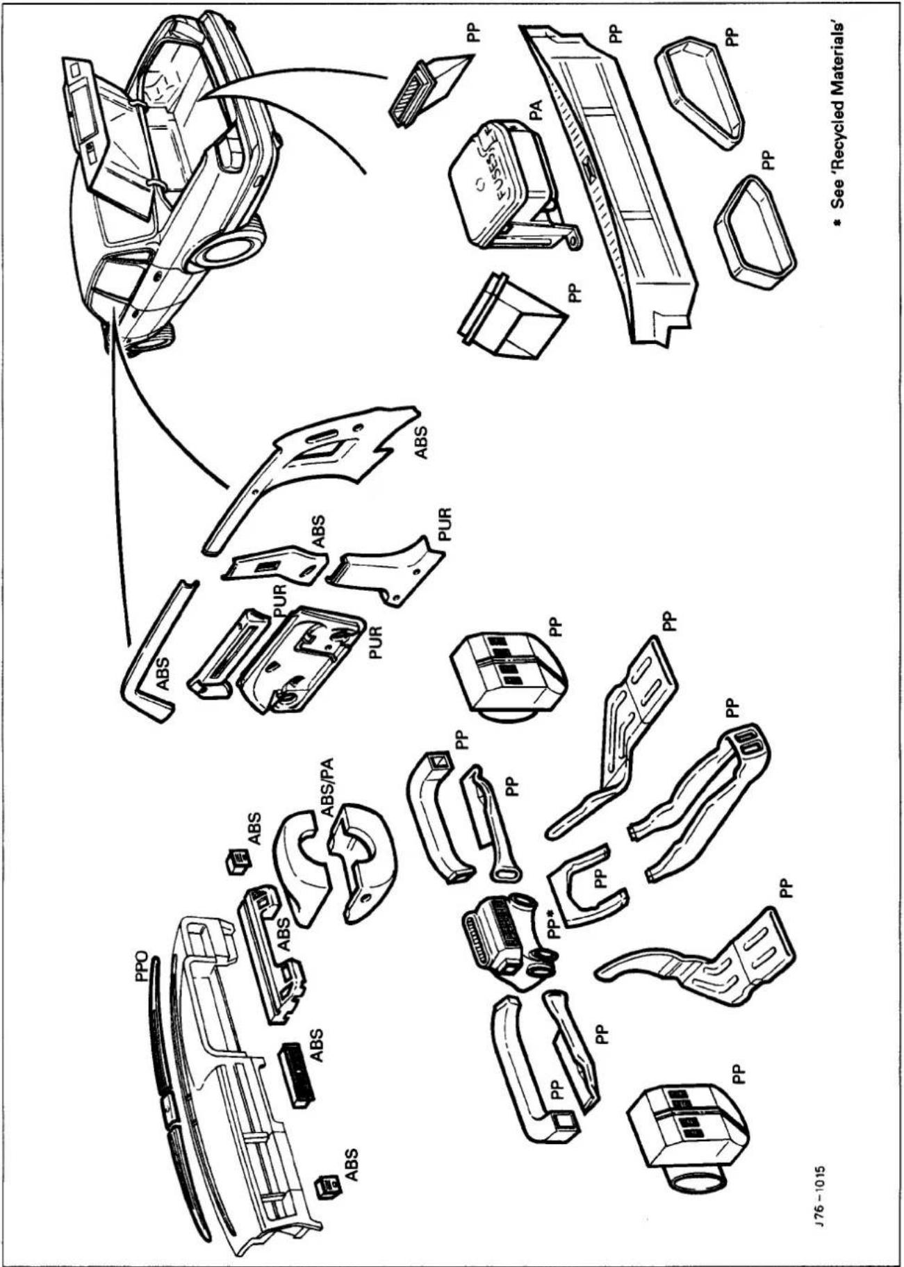
A4.1.6.6 Plastics, Component Location & Type - Under-hood

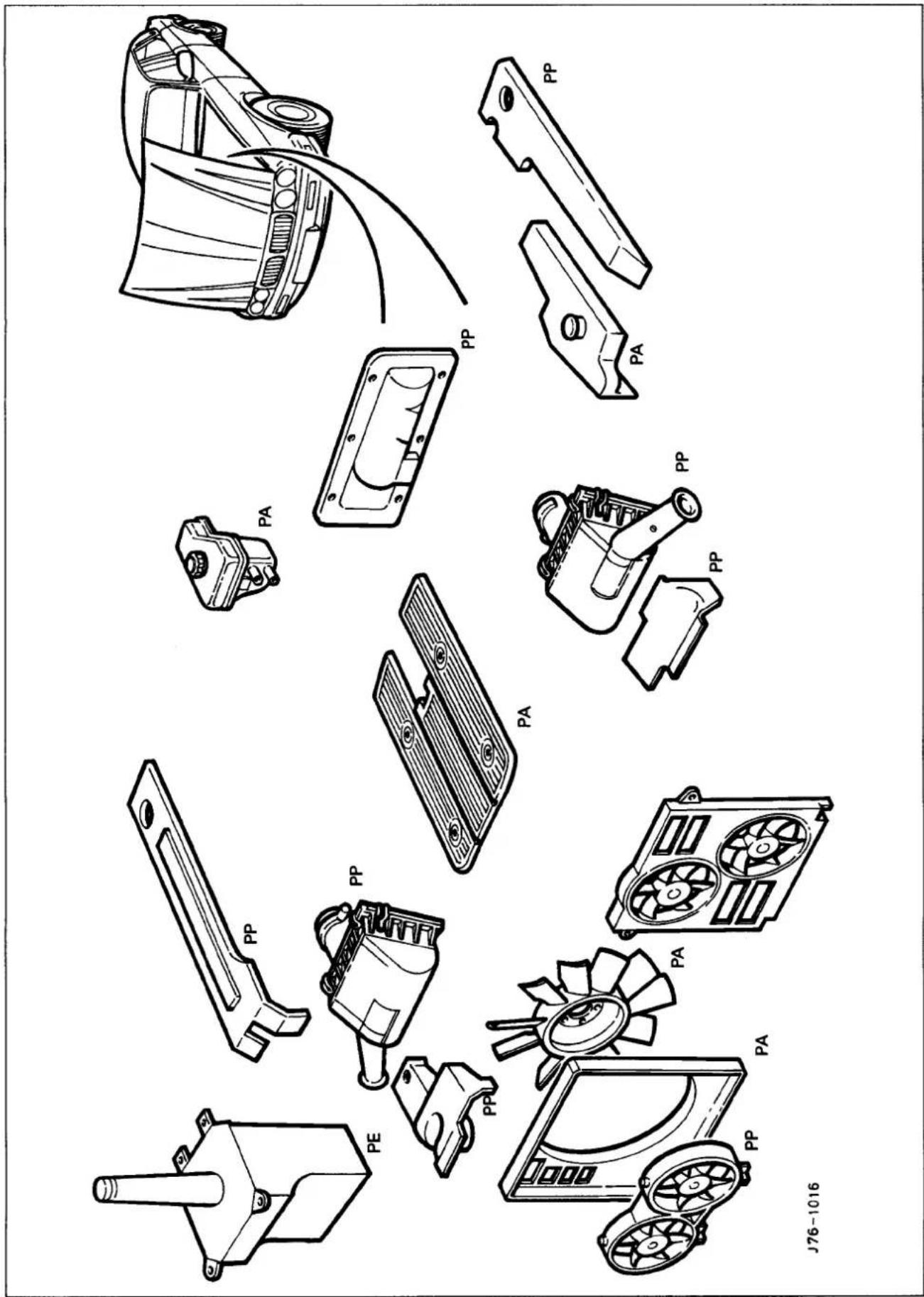

A4.2 BODY STRUCTURE
A4.2.1 Introduction
The Jaguar sedan range (with standard wheelbase) has a unit construction monocoque body structure with bolt-on front fenders and welded rear fenders. The doors feature 'lift-off' hinges and welded drop-glass frames.
A4.2.1.1 Constructional Steel Classification
| Material | Application |
| High strength low alloy(HLSA). | Impact prone areas, ie. seat frame and bumper mountings. |
| Double sided zinc plated mild steel. | Exterior body panels subject to severe conditions such as stone chipping and weather exposure (excluding roof panel). |
| Boron steel | Door intrusion beams |
| Mild steel. | Internal brackets, fillets and strengtheners. |
A4

A4.2.2 BODY ALIGNMENT
The illustrations on pages11- Body DimensionsPLAN, and 13-Body Dimensions SIDEVIEW, provide specifications for damage assessment and location of replacement parts.
These dimensions must be strictly applied whether they are used for damage assessment, component location or post repair verification.
The plan view MASTER datums are nominated on the right-hand side of the body with the left-hand datums dimensioned from them. Therefore, the right-hand datums must be known to be correct before any other cross—ar dimensions are checked.
Note: The right-handside is always looking towards the front, from the rear of the vehicle.
All dimensions are derived from a single (ZERO) datum point for all three axes; X for length, Z for height and V cross-car.


A4.2.2.1 Datum location, Example
The FRONT MASTER DATUM (frontcrossmember rear mounting at the inner face of the mainfloor RH longitudinal) is nominally 359.5mm to the right-hand side of the body center line. The LH side front datum is measured 717.0/721.0mm from the RH. Please refer to the illustration on the following page.
Expressed as a true position in three planes, the front master datum is:
| Datum | Location | Position |
| Front Master Datum Plan | Centre line of the front crossmember rear mounting, at the main floorRH longitudinal | X 300,0Y 359.5Z -50.0 |
A4
A4.2.2.2 Key, Plan View
Please refer to the illustration on the opposite page.
| Key | Location |
| 1 | Front face body - bumper strut/ mounting point |
| 2 | Rearmost hole, Vee-mount to crush tube |
| 3 | Front Master Datum Plan, centre line of the front crossmember rear mounting at the main floor RH longitudinal |
| 4 | Rearmost hole, transmission mountingat the main floor RH longitudinal |
| 5 | Driveshaft centre bearing fixings |
| 6 | Rear Master Datum Plan, rear longitudinal |
| 7 | Tapped boss, rear suspension 'A' frame mounting bush |
| 8 | Rearsuspension spring -pan damper mounting |
| 9 | Rearsuspension differential strut mounting |
| 10 | Rearface body - bumper strut/ mounting point |
0

0

J76-1038

Fig.1 Body Dimensions - Plan View
A4
A4.2.2.3 Key, Side View
Please refer to the illustration on the opposite page.
| Key | Location |
| 1 | Front face body - bumper strut / mounting point |
| 2 | Front Master Datum Vertical, centre line of the front crossmember rear mounting |
| 3 | Transmission mountingsat the main floor longitudinal |
| 4 | Driveshaft centre bearing fixings |
| 5 | Rear Master Datum Vertical, rear longitudinal |
| 6 | Tapped boss, rear suspension 'A' frame mounting bush |
| 7 | Rearsuspension spring-pan damper mounting |
| 8 | Rearsuspension differential strut mounting |
| 9 | Rearface body - bumper strut / mounting Point |
| 10 | Wheel centre to bumper cover face |
| 11 | Wheel base |
| 12 | Wheel centre to bumper cover face |
A4

A4
A4.2.3 ZINCOATED PANELS
A4.2.3.1 Description
Approximately 65% of the 'body in white' (BIW) mass is made up of zinc coated panels.
All exterior skin panels, with the exception of the roof, are double side zinc plated and this coating (nominally 75 microns) provides corrosion protection in two ways.
- Should the outer layer of paint become chipped but the zinc coating remain intact, the zinc will oxidize on contact with air. This coat of oxidation is impermeable and will prevent corrosion damage to the base metal.
- If both the outer layer of paint and the zinc coating become damaged, the zinc will react with the air and 'sacrifice' itself to corrosion, rather than the base metal. In this process the zinc is known as a 'sacrificial anode'.

Note: Tomaintain the protective qualities of the zinc treatment, repairs to any damaged coated area MUST be made as soon as possible after the damage has occurred.
A4.2.3.2 Welding Preparation
Where 'resistance spot welding' is employed, the zinc coating should be lightly abraded away on the mating surfaces and those in contact with the electrode tips. Do not remove more of the zinc coating than is absolutely necessary. Before welding, a weld-through primer or inter-weld sealer should be applied, as detailed in the Body Sealing and Preservation manual.
Contamination of the weld will occur if the plating is not removed, thus making the joint less strong; another side effect of this will be a greater need for electrode tip dressing and increased tool down time.
In exceptional cases where the plating must remain intact, increasethe tip pressure and welding current by 10to 20%.
Where MIG welding is used as an alternative to resistance spot welding for plug, butt welds, or limited access, the problems caused by the presence of zinc coating are much the same as those previously mentioned. There may also be the added problems of increased weld spatter and nozzle contamination.
A4.2.3.3 Body Fillers
Conventional polyester fillers do not adhere satisfactorily to zinc plated panels. Therefore, it is important to use only those products specifically designed for this application and follow the manufacturers recommendations.
A4.2.3.4 Refinishing
Use only those products approved by Jaguar Cars Ltd and take special care with zinc coated panels.
Replacement panels are supplied ready primedso there should be no need for bare metalto be exposed, other than those areas prepared for welding etc (see 'Welding Preparation' sub section 4.2.3.2).
Where any part of a panel is dressed back to a bare surface, it should be treated with a zinc rich primer compatible with the chosen paint application system, please refer to section A4.4.1.1.
A4.2.4 PANELS — ASSOCIATED, RENEW
SRO 77.10.02
Note: Where other components must be removed to gain access, pleaserefer to the relevant manual section for guidance. This is critically important with regard to steering, braking, suspension, electrical and safety systems.
■ Exposethe resistancespot welds, for those spot welds which are not obviously visible, use a rotary wire brush fitted to an air drill or a hand held wire brush (A Fig. 1).
WARNING: DO NOT BURN UNDERSEALOFF. USE A 'HOT KNIFE' OR SUITABLESOLVENT.
- Cut out the spot welds using a Zipcutter or Roto-Bor (B Fig. 1).
At this point it may be necessary to cut out the bulk of the panel using a pneumatic saw (C Fig. 1).
Note: On some panels, before removing the bulk of panel with the pneumatic saw, brazed areas and MIG welded seams should be removed. - Separate the spot welded joints and remove the panel remnants.

Fia. 1

A4


A4.2.5 SURFACES (OLD), PREPARE
SRO 77.10.03
- Observe all appropriate safety procedures.
WARNING: DO NOT BURN UNDERSEAL OFF. USE A 'HOT KNIFE' OR SUITABLE SOLVENT
■ Remove the weld nuggetswith a sander and 36 grit disc.
- Clean all flangesto a bright smoothfinish. (A Fig. 1).
- Straighten existing panel joint edges as required.
A4.2.5.1 SURFACES (NEW), PREPARE
SRO 77.10.04
- Observe all appropriate safety procedures.
■ Mark off the area of new panel and cut to size leaving approximately two inches overlap on the existing panel. Offer upnew panel or section, and align with associated parts, i.e. new rearfender aligned with door / luggage compartment lid/ backlight aperture.
■ Clamp the panel into position. - Where necessary, cut the new and original panels to form a butt joint.
■ Remove all clamps and the new panel.
■ If required, apply inner panel protection and or sound insulation. - Prepare the new panel joint edges for welding by cleaning to bright metal (A Fig. 1); this includes all interior and exterior edges.
- Apply weld-through primer or interweld sealer (B Fig. 1) to all surfaces tube resistance spot welded.
- Where appropriate, apply metal-to-metal adhesive or sealer (C Fig 1) in accordance with the manufacturer's instructions.

A4.2.5.2 PANELS, ALIGN AND WELD
■ Observe all appropriate safety procedures.
■ Apply appropriate sealer or joint preparation.
- Align the replacement panel with associated panels and clamp in position; with certain panels it may be necessary to MIG tack weld (A Fig.1) or use 'PK screws.
■ Recheck alignment and panel contours and re-adjust as necessary.
- Select the correct 'arms' for resistance spot welding and ensure that tips are correctly trimmed.
Note: It is recommended that 'arms' of not more than 300 mm (12 in.) long are used and test the equipment for satisfactory operation by producing test coupons (B Fig. 1). In the absence of test equipment, a satisfactory weld can be verified by pulling the test coupons apart and viewing the welded condition.
■ Resistance spot weld where required (C Fig. 1).
■ Note the presence of zinc coated panels and treat as detailed in the previous sections.
■ Dress back all MIG tack welds.
■MIG seam weld the butt joints(D Fig. 1).
■ As required, dress all welds.
■ Final braze and fill as necessary prior to paint preparation.
A
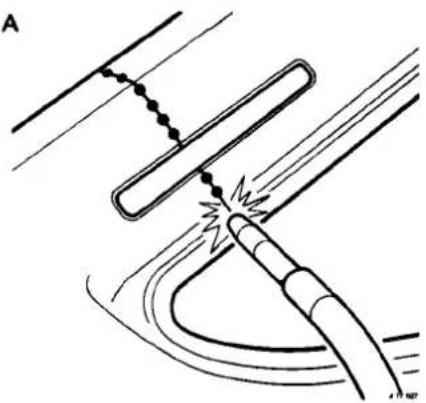
B

47908
C

D

Fig. 1

A4


A4.2.6 CUTTING AND WELDING SYMBOLS
A4
- Saw Cut
- Chisel Cut
- Cut Out Spot Weld
- Resistance Spot Weld
- MIG Tack Weld
- MIG Seam / Butt Weld
- 23
- Gas Weld
- MIG Plug Weld


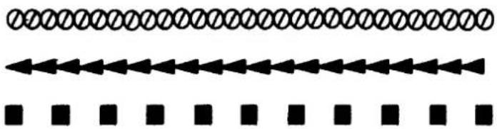
Fig. 1 Key to symbols
CAUTION: Reference should always be made to the welding tables and illustrations in the relevant procedures. Observe all safety precautions with respect to yourself, other people, your equipment and the workplace.
A4.3.1 ADHESIVES, SEALERS AND BODY PROTECTION - APPROVED SYSTEMS
Specifications and recommendations may be found in the 'Body Sealing and Preservation Manual' which is available in the following languages:
| Language | Reference |
| Dutch | AKM 9165 |
| English | AKM 9137 |
| Italian | AKM 9164 |
| French | AKM 9162 |
| German | AKM 9163 |
| Japanese | AKM 9178 |
| Spanish | AKM 9166 |
A4
| Section | Relevance |
| Cavity wax injection points | Not applicable, see A4.3.2 for specific injection points |
| Underbody & underhood wax | Not applicable |
| Approved paint refinish processes | Not applicable, see section A4.4.1.1 |
| Health and Safety | Legislation applicable U.K. only; general precautions and advice applicable to all |
A4.3.2 CAVITY WAX INJECTION
Protective wax should be applied in the locations as specified in the following illustrations. Please refer to the 'Body Sealing and Preservation Manual' for processes, materials and equipment.
Note: Cavity wax processes should only be applied after ALL other refinishing and protection procedures are complete.
A4.3.2.1 Cavity wax injection points - Front
A4

A4.3.2.2 Cavity wax injection points–Rear
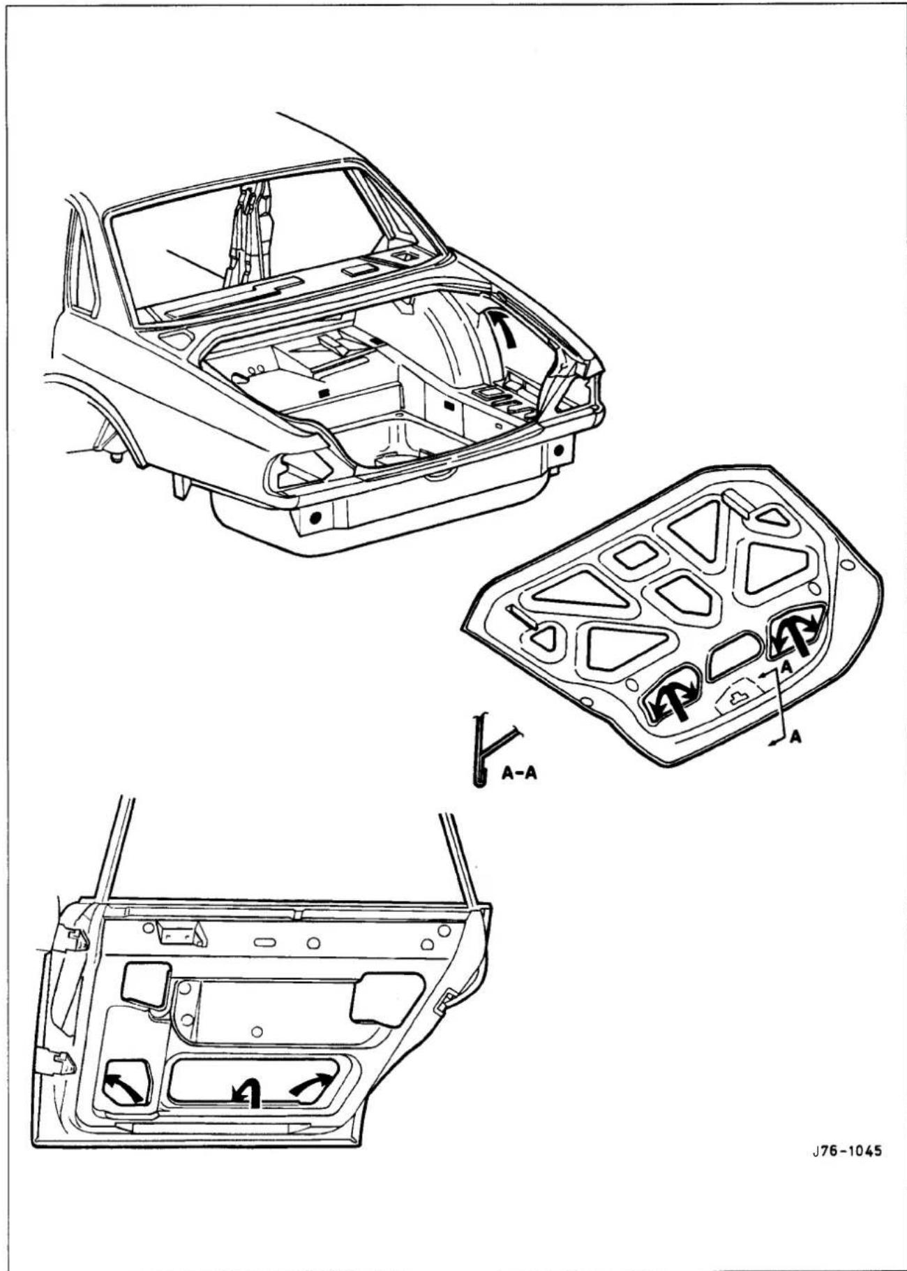
A4.3.3 UNDERSEAL, APPLICATION
Inderseal should be applied as indicated by the 'hatching' and omitted from areas indicated in solid black.
A4


= Areas to be left clear
Fig. 1
CAUTION: Do not apply underseal to rotating or hot components.
A4.3.4 INSULATION PADS
Insulation pads should be located in accordance with the illustration below.

A4.3.5 FOAM INJECTION
Where any of the sections shown in the following illustration are renewed, then expanded foam must be introduced into the area after all other repair / refinishing / protective processes.
- Tape should be applied to the areas defined by arrows to ensure the travel of the foam along the hollow section.
- Expanded foam should be introduced into points circled in Fig. 1.
- Items such as sliding roof drain tubes and the harness from the rear left-hand bulkhead through to the luggage compartment, must be in position BEFORE the introduction of the foam.
A4

A4.4.1 PAINT SYSTEMS - APPROVED
The manufacturer's paint systems listed below are currently approved for refinishing Jaguar vehicles.
| Manufacturer | Bare metal etch primer | Primer surfacer | Base color coat | Clear lacquer |
| Akzo Sikkens | Washprimer | Autocryl / Autonova | Autobase | Autoclear 1000 - 3000 Automat |
| Dupont | Centari 600* | Centari600* | ||
| Glasurit | Wash Etch+ System 54 | (solid/metallic)System 56 (micatallic)System 59 & 69 (pearl) | Clear lacquer 923-85 | |
| Herberts | Metal pre-treatment & rust remover 301.2595 | Standox Basislak | Standox Clearlak | |
| ICI | Autocolor | |||
| PPG | Galvaprep D840 | Wash primer D831Hi-build primer D855Epoxy surfacer DP40Deltron/ non Iso-cyanate Primer D828 | Deltron HS 2 | Deltron Concept 2001 HSclear D880 |
| R-M | Eurofill | R-M Prof/Maxfill | Diamont Basecoat | Diamont Clearcoat |
Note: * Not available North America
In markets which do not support any of the nominated systems, alternatives may be used, provided that they comply with the following company standards.
| Product type | Applicable standard |
| Bare metal etch primer | JMS 20.29.06 |
| Primer surfacer | JMS 20.29.11 |
| Base color and clear lacquer | JMS 20.29.09 |
CAUTION: To avoid damage to the vehicle interior, trim and plastic items, effective panel temperature must not exceed 95°C during paint cure process.
A4.4.1.1 General Recommendations
Recommendations and advice covering all aspects of refinishing may be found in the 'Paint Refinishing Manual' which is available in the following languages:
| Language | Reference |
| Dutch | AKM 9187 |
| English | AKM 9182 |
| Italian | AKM 9185 |
| French | AKM 9183 |
| German | AKM 9184 |
| Spanish | AKM 9186 |
A4.4.1.2 Manual Section Relevance
| Section | Relevance |
| Defect diagnosis | Applicable |
| Refinish processes | Applicable less 'De-waxing' process |
| Refinishing system | Applicable less model references (see table above) |
| Color technique | Applicable |
| Facilities and equipment | Applicable |
| Safety | Legislation applicable U.K. only; general precautions and advice applicable to all |
A4.4.2 'BLACK-OUT' AREAS
To avoid visibly unsightly areas between panels and through gaps, the application of matt black paint is required in certain areas. It should be noted that this process is NOT required on dark colored vehicles. The paint, which should have a heat resistance of 40° to 120° C should be applied in accordance with Fig. 1 to the areas marked with an asterisk (*).
A4
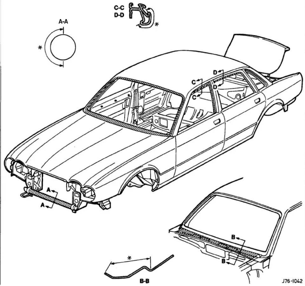
Fig. 1

A4.4.3 ANTI -THEFT LABELS, (NORTH AMERICAN MARKET ONLY)
A4.4.3.1 Original Components
North American specification vehicles have the VIN marked on all major external panels, certain structural members and power/transmission units. The labels which carry this information are known as 'Label - anti-theft VIN (USA body panel only)' or 'Label - anti-theft - engine and gearbox (U.S.A. only)' (A Fig. 1), see location illustrations.
A4.4.3.2 Replacement Components
When a vehicle suffers damage, only genuine Jaguar replacement panels/units should be used in the repair; further, if any parts originally carried a VIN label then a different type of label MUST be affixed 'Label - anti-theft replacement part (USA body panel only)' or 'Label - anti-theft replacement part - engine and gearbox (U.S.A. only)' (B Fig. 1), NOT in the same location as the previous label, see location illustrations.
A protective mask is used to prevent the replacement part label from being damaged or obscured during the refinishing / protection processes. This protective mask MUST be removed prior to customer hand-over.
Note: All service panels are supplied in electrocoat primer and where appropriate MUST have an anti-theft label in the correct location.
A4.4.3.3 Procurement
Anti-theft labels may only be ordered from Jaguar Cars through:
Product Compliance Dept.,
Jaguar Inc.,
555 MacArthur Blvd..
Mahwah
NJ 07430


J76-1041
Fig. 1


A4.4.3.4 Location Of Anti-theft Labels - Front
A4
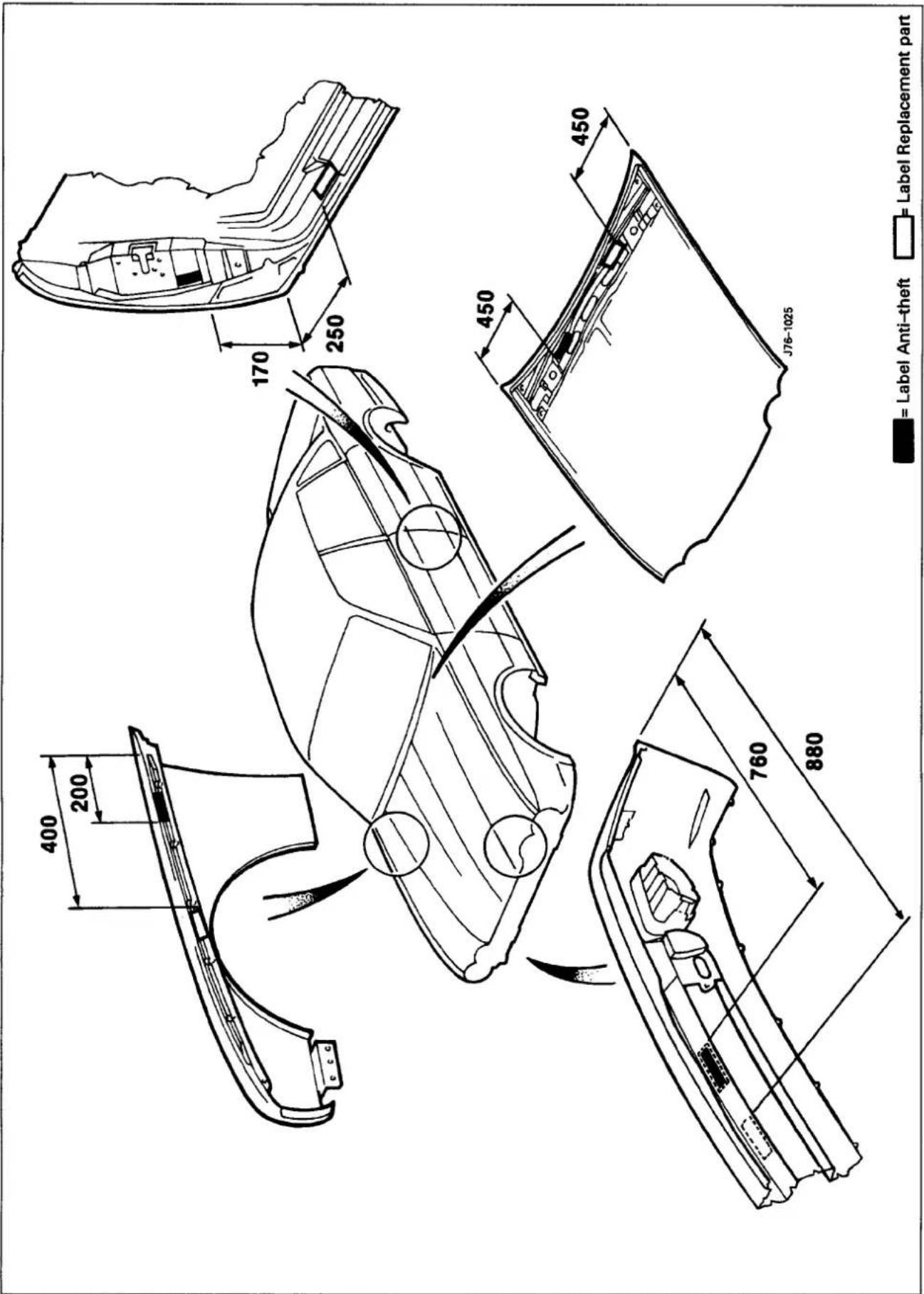
A4.4.3.5 location of Anti-theft labels - Rear

A4.4.3.6 Location of Anti-theft Labels - Power unit and Transmission


A4.4.3.7 Fitting Process
- Fit and fully secure the replacement panel(s), if appropriate.
- Using a suitable solvent clean the area where the anti-theft label should be affixed.
- Peel the backing from the label and position on the panel.
- Carry out ALL refinishing / protection processes.
- Remove the anti-theft label protective mask prior to vehicle handover to the customer.
Note: Any attempt to remove an anti-theft label will destroy that label. Please ensure correct location before affixing.

CAUTION: It is a requirement of the United States of America federal law that the protective mask is removed from the anti-theft label after performing painting and rustproofing operations. FAILURE TO COMPLY MAY RENDER BOTH THE MANUFACTURE AND THE DEALER IN VIOLATION OF THE FOLLOWING LAWS.
| Statute | |
| Federal Motor Vehicle Theft: | 51 FR 8831, at 8835, March 14 1986 Prevention Standard |
| Motor Vehicle Information: | 15 U.S.C. 2027(a) (4) (B) and Cost Savings Act 2027(b), sections 607(a) (4) (B) and 607(b). |


A4.4.4 UNDER-HOOD LABELS
A4

A. Power steering-Warning
B. Shock absorber fixings -Warning
C. Brake fluid type -Warning
D. Clutch fluid type -Warning
E. Coolant pressure/temperature - Warning
F. Headlamp beam setting adjustment
G. Emission control data
H. E11 legislation label (not all markets)
J. Rotating components- Warning
K. Vacuum pipe routing
A4.4.5 STONE-CHIPROTECTION, APPLICATION
The approved material should be applied to the areas indicated.
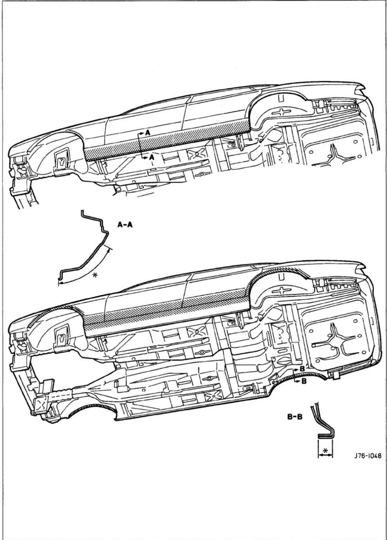
A4
A4.5 GLAZING
A4.5.1 Special notes
In order that the design condition of the vehicle is preserved when direct glazing repairs are carried out, it is essential that both the applied materials and processes are as stipulated.
A4.5.1.1 Glass and Body Preparation
A4
The preparation methods and materials, as used with the Betaseal HV3 system on previous Jaguar vehicles, are fully compatible with the current sedan range.
Ease of working and extended process time may be gained by ensuring that the vehicle body and replacement glass are 'soaked at room temperature, a minimum of 20°C, prior to adhesive application and fitting.
Should damage occur to the body flange finish, rectify as appropriate with the full paint refinishing process as described in the 'Paint RefinishingManual' see section 4.4.1.1.
A4.5.1.2 Adhesive Application Temperature
The specified adhesive has a high viscosity and is not easily applied at 'room temperature' using conventional methods. When the adhesive is applied it chills rapidly on contact with the body and revert to the hard condition, thus providing full retention (not full strength) within minutes.
Raising the temperature of the adhesive lowers the viscosity and speeds up the flow. It is recommended therefore that the adhesive is pre-warmed in a heated cabinet fora minimum of 20 (twenty) minutes and the extrusion gun has integral heating elements, see Preliminary pages for details.
| Application time - including positioning | ||
| Optimum temperature | 60°C -70°C | 4 minutes |
| Maximum Temperature | 75oc | |
| Minimum temperature | 35°C | Will not bond |
A4.5.1.3 Adhesive Application
CAUTION: The glass will not bond to the body if the time taken to apply the adhesive AND position the glass. exceeds the stated limit.
It is recommended that the bead of adhesive conform to the shape and dimensions as shown in Fig. 1 and is positioned along the edge of the rubber.
Note: The depth of the glass and thus the thickness of the adhesive, is controlled by the screen rubber 'bottoming' on the body flange.
A4.5.1.4 Adhesive Curing
The specified polyurethane adhesive cures by exposure to moisture and NOT by heat. Cure times may vary considerably and are dependant upon ambient humidity levels, however the initial 'chilloff will occur within Ito4 minutes, after which the screen may not be moved (this is entirely dependant upon the application temperature and rate of cooling).


A4.6.1 BUMPERS
A4.6.1.1 Major Components
The sedan range bumper system comprises of:
○ Bumper cover.
Mounting struts.
Beam.
- Guide blocks.
- Integrated lamps.
○ Chromium plated stainless steel upper trim blades.
Brake ducts.
Under tray.
Grille vane
Note: See illustration, following page.
A4

A4.6.1.2 Features
One-piece moulded bumper / spoiler, finished in body colour (see note, sub section A4.1.6).
- All components and harnesses may be sub-assembled on the bench and the complete assembly then fitted to the vehicle.
- Fully height adjustable front and rear (strut or mounting) and side (guide block).
Energy absorbing struts on North American market vehicles, which comply with US and Canadian legislation (FMVSS 007 and CMVSS 215).
- Fixed struts on 'rest of world' vehicles.
- Aluminium beam on North American market vehicles.
- Plastic beam on 'rest of world' vehicles.
○ Indicator, fog and reflective (or illuminated) side marker lamps are removable from front and the fog lamps are adjustable from beneath.
○ Blanking grilles fitted where fog lamps are not specified.
Note: The grille vane MUST be removed before the front towing eye may be used. Quick release fasteners fix the vane to the cover and are accessed from the front.

A4
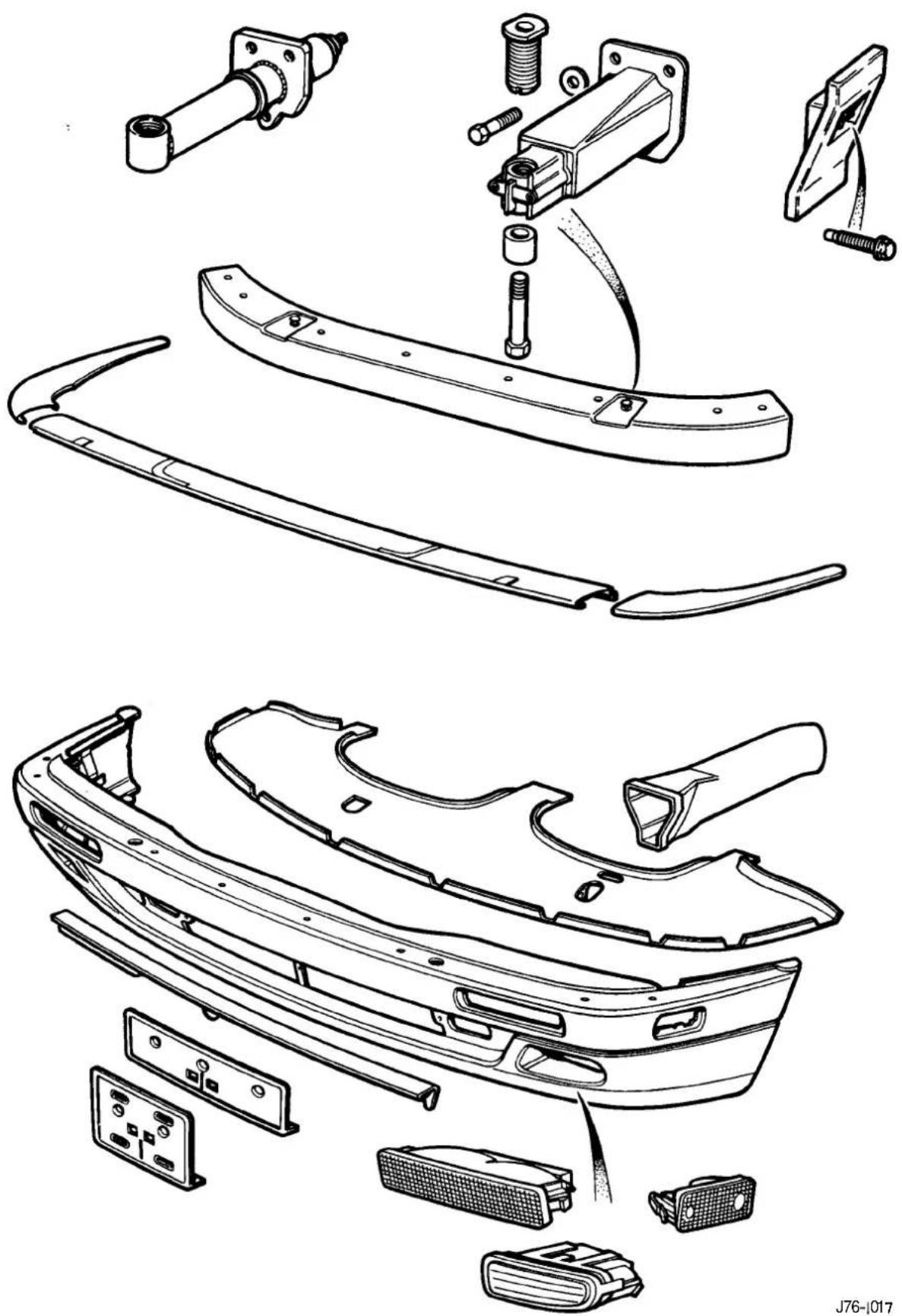
Fig. 1 Front bumper - Typical components
A4.6.1.3 SERVICE PROCEDURES
A4.6.1.4 Fitted Condition (Front)
The following procedures may apply should any part of the bumper mounting system, or cover, be renewed but should not be necessary if the cover is removed for service reasons.
- The front mountings must initially be set for 'cross car' pitch and center within the clearances around the strut to body fixings.
- In order that the bumpertopface, headlampsurrounds and grille lower have the correct relationship the strut height adjusters must be finally set AFTER the cover is fitted.
- Set the guide blocksto thespecified dimension to achieve the correct bumpertofender gap, BEFORE fitting the cover because adjustments can only be made with the cover off.
■ With all fixing points set, the bumper cover may be fitted and adjusted as necessary to achieve the specified gap conditions.
■ Tighten all fixings to specification.
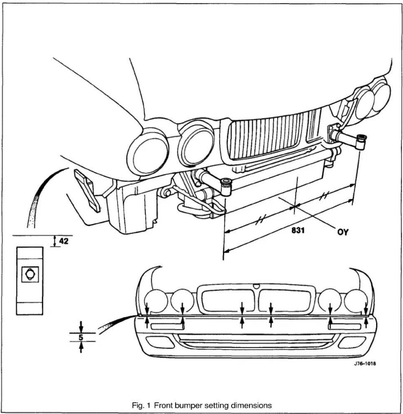


A4.6.1.5 Fitted Condition (Rear)
The following procedures may apply should any part of the bumper mounting system, or cover, be renewed but should not be necessary if the cover is removed for service reasons.
■ The rear mountings must initially be set for 'cross car' pitch and center within the clearances around the strut to body fixings.
■ To initially achieve the relationship between the bumpertop face and the rear panel, the strut height adjusters should be set to the dimension shown (Fig. 1) BEFORE the cover is fitted.
- Settheguide blockstothespecifieddimensiontoachievethecorrect bumpertofender gap, BEFORE fitting the cover, because adjustments can only be made with the cover off.
■ With all fixing points set, the bumper cover may be fitted and adjusted as necessary to achieve the specified gap conditions.
Note: Access to the beam height adjusters may be made with the cover fitted by removing the tailpipe trims.
■ With the bumper correctly adjusted to the body and all fixings tightened to specification, it is important that the exhaust tailpipes are then centered within the bumper cover cut-outs. This may be achieved by slackening the rear section clamp and rotating the rear exhaust assembly. Please note that this may only be achieved before the tailpipe trims are fitted; these must also be correctly aligned for good appearance.

A4.6.2 COVER DAMAGE
A4.6.2.1 Damage Assessment
Prior to any action, damage should be assessed and categorized in accordance with the following, noting that if the cover has been 'holed' or torn, it should be discarded. The following categories are the only conditions which may be repaired.
| Category | Damage |
| Cosmetic | Abrasion to surface paint finish only |
| Substrate surface | Deep scratches, gouges or localized radial stress cracks. |
| Substrate penetration | Splits not exceeding 100mm. Splits radiating from a gouge and accompanied by localized stress cracks. |
A4
CAUTION: Cosmetic appearance must not override safety.
Damage beyond category three will compromise the protective performance of the unit should repairs be effected, the cover MUST be renewed.
Due to the therm-setting nature of the cover material, it is NOT possible to repairs splits by heater welding.
A4.6.2.2 Repair Materials
Repair of accepted damage for categories 2 and 3 may be carried out using products from;
3M '5900 FPRM' (Flexible part repair material)
Kent Industries 'Urepatch'
It is essential that the repair product manufacturer's recommendations and procedures are followed carefully.
A4.6.3 REFINISHING
The paint refinishing system must be approved by Jaguar Cars Ltd., and be appropriate for polyurethane substrate application. It is important that the finishing clear lacquer includes a plasticising ingredient (mixed to the manufacturer's recommendation) to reflect the 'semi-flex' condition of the factory finished item.
The effect of heat decreases the cover rigidity to the point that paint-cure temperatures require that the cover must be supported to prevent distortion and sagging; these comments apply to 'off-car' repairs.
A4.6.3.1 Original
On an original unit where damage has been repaired, the beam will provide sufficient support for the forward part of the unit. It is recommended that the side armatures are supported as they would be on the vehicle.
A4.6.3.2 New
Where a new cover is required, the beam may be temporarily fitted prior to painting to provide the necessary support.
A4.6.3.3 All
Asimple jig (Fig.1) should be made to hold the unit in the correct working attitude for both damage repair and finishing.
CAUTION: During heat cure, the effective panel temperature must not exceed 95°C.

A4.6.4 REPLACEMENT COVERS
Replacement covers will be supplied in a primed condition and therefore must be finished in accordance with A4.6.3, this page.
Bumper covers and replacement fixings such as bumper beam adjusters and guide blocks must be fitted and adjusted as detailed in A4.6.1.4 and A4.6.1.5, this section.
A4.6.5 RECYCLED MATERIALS - GENERAL NOTE
The aluminium bumperbeam, as fitted to North American specification vehicles, should not be over-looked as a component for recycling.
Side armatures will be fully assembled in replacement bumper covers, please see 'note' Recycled materials, this section, for important information.
A4.6.6 BODY-SIDE MOULDINGS
A4.6.6.1 Introduction
There are two types of moulding fitted to the standard wheelbase sedan.
The lower moulding is 'self-locating' on the body / door lower feature line and therefore provides a fixed datum for the location of the upper moulding (wherefitted). Replacementlower mouldings will be supplied in a primed condition and therefore must be finished in accordance with A4.6.3, this section.
| Location Finish Application Fixing | method | ||
| Upper | Polished stainless steel Daimler / VDP | / VDP | Adhesive tape |
| Lower Bodv | color | All models | Adhesive tape |
A4.6.6.2 Body-side Moulding - Fitted Condition

- Adhesive tape
- Moulding, Daimler/VDP.
- Moulding, All models
Fig. 1
A4.6.6.3 Fitting process
■ 'Spirit wipe' appropriate body panel and where appropriate protect against damage.
■ Gently warm body panel and moulding using infa-red lamp or similar.
■ Lower moulding- align to body feature and other mouldings if appropriate, and secure into position.
■ Upper moulding - align to lower moulding for distance (Fig. 1) and parallelism and other mouldings if appropriate, and secure into position.
■ Apply an even pressure along the moulding to fully secure to the panel.
A4.6.7 FINISHER - DOOR FRAME
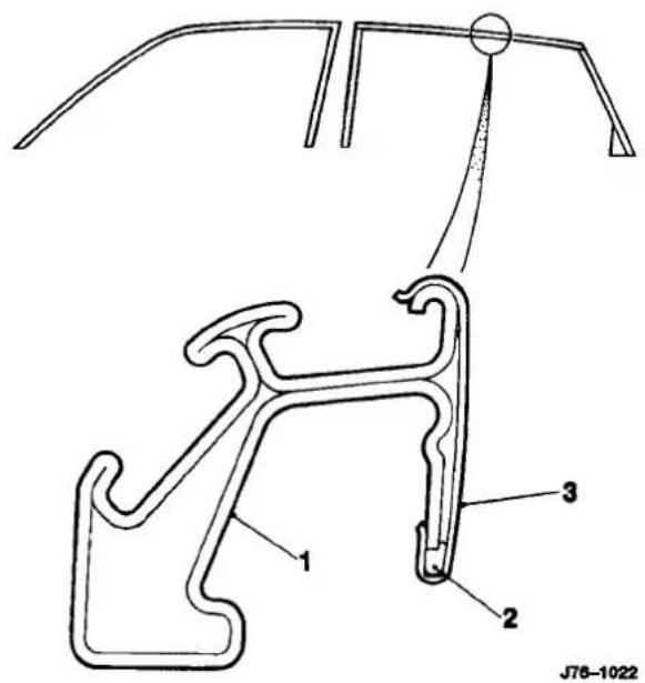
- Section, door frame
- Compression cord
- Frame finisher
Fig. 1
+
A4.6.8 FINISHER - ROOF DRIP RAIL


J76-1037
- Section, roof
- Drip rail finisher assembly
- Assembled condition
Fig. 2

A4.7.1 BODY EXTERIOR CLEARANCES AND ALIGNMENTS
A4.7.1.1 Introduction
Wherever a panel, closure or component is renewed, refitted or reset, the factory specifications for clearance (gap) and alignment (profile) MUST be attained.
There is no distinction between the importance of visual and operational characteristics; all conditions must be satisfied so that the vehicle looks and operates to the satisfaction of both design intent and the customer.
A4.7.1.2 Criteria - Clearances
- Gaps should be uniform around body panel contours.
- Gaps must be parallel to within 1mm in a 400mm linear measurement.
Panels which are centered between 2 (two) adjacent panels must have equal gaps either side; there are exceptions to this, please refer to the appropriate specification. - Gaps between adjacent panels or components must not expose harnesses, labels, brackets or visually poor joint or assembly conditions.
Particular areas of concern:
Fuel filler flap.
Trunk lid to fenders and saddle.
Hood to fenders, grille and headlamps.
Sliding roof panel to the main roof panel.
Door gaps at fender, B/C' pillar, roof drip rail and rocker panel.
Bumper cover to fender and cross car assemblies (see section A4.6.1.4 & A4.6.1.5).
Note: Please note that the sliding roof panel clearances are specified WITHOUT the edge seal, refer to the illustration on the following page.
A4.7.1.3 Criteria - Alignment
Panels must be correctly 'profiled' to maintain cosmetic appearance, pressure on seals and control wind noise.
Particular areas of concern:
Hood to fender.
Trunk lid to fender and saddle.
Door to aperture.
Door to fender and adjacent door.
The relationship of the sliding roof panel leading and trailing edges to the main roof panel.
A4.7.1.4 Criteria - Exterior Fitments
- Bezels, trims and lamps must be centered within apertures and have equal clearances with adjacent panels.
Particular areas of concern:
Headlampto hood, fender and trim panel.
Exhausttailpipe trim to bumper cover cut-out.
Rear lamp assembly to trunk lid, fender and bumper cover trim.
Feature lines fender to door and door to door (this includes body side mouldings).
A4.7.1.5 Exterior clearances and alignments, Illustrations
Specifications for gaps and profile may be found on the illustrations on the following three pages.


A4
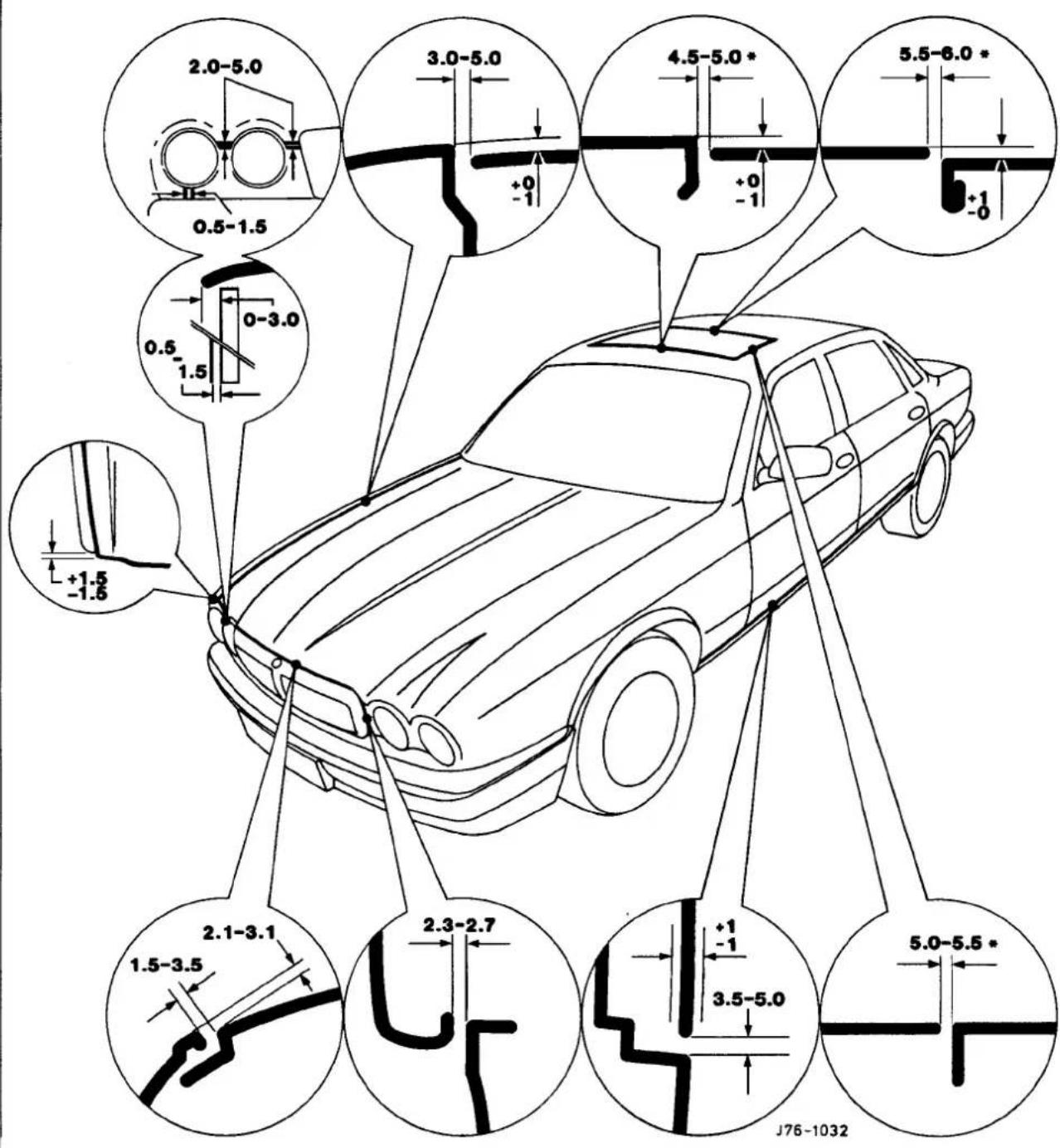
• Refer to A4.7.1.2, this section
Fig. 1

Fig. 1
A4
A4
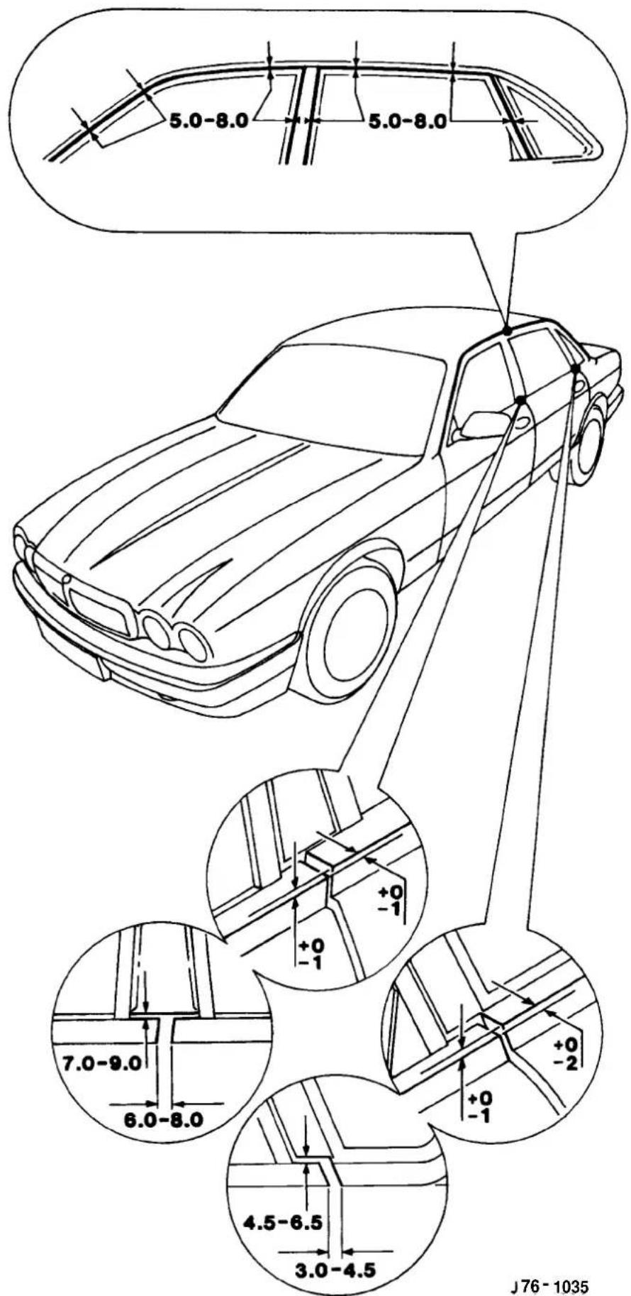
Fig.1

A4.7.2 DOORS
A4.7.2.1 Features
The doors feature:
Lubricated for life 'lift-off' hinges.
Welded drop glass frames.
Integral primary and secondary seal channels.
A4.7.2.2 Removal
■ Apply tape as Fig. 1 to avoid paint damage during the removal process.
- Disconnect door harness at connector.
■ Remove locking screws Fig.2.
- Disconnect check-arm fixings at the body Fig. 2.
- Open the door fully, carefully lift and disengage from the hinge pins,

A4.7.2.3 Fitting
■ Before re-fitting the door assembly, all traces of thread locking compound must be removed from the hinge pins; careful use of a suitable thread tapis recommended.
■ Refit the door assembly and secure to specification using new locking screws.
Note: There is no need to lubricate the hinge when refitting the door.
■ Apply grease to the check-arm 3 Fig. 2
■ Ensurecorrect alignment and remove the protectivetape.
A4.7.2.4 Alignment
Hinges are set during the body manufacturing process and should not require adjustment during the life of the vehicle. However, where damage has been sustained at the body or door hinge location points, please refer to 'Body fits and clearances' section A4.7.1.5 for setting criteria.

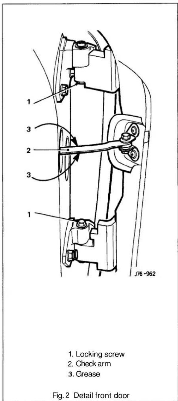


A4.7.2.5 Seals
| Title Material | Location | Fixing method Note | ||
| Primary | Sponge rubber, hollow section frame and 'pegged' to | Door periphery | 'C' channel in upper door inner panel | |
| Secondary Sponge rubber, solid section | Door upper frame | 'C' channel in frame Outboard of primary | ||
| Draught welt | Metal reinforced rubber extrusion, cloth covered | Door aperture periphery | Flange edge straddle | |
A4
A4.7.2.6 Typical Door Seal Sections
The relationship of the seals to the door and body aperture can be seen in Fig.1. Please note that the seals are shown in the natural state, ie not deformed by the door being in the fully closed position.

- Section, roof/door aperture
2 Primary seal - Draught welt
- Section, door frame upper
- Secondary seal

A. Section, door lower at waist
B. Draught welt
C. Section, body aperture at waist
D. Primary seal
E. Peg, primary seal to door
Fig. 1

SECTION CONTENTS
Sub-Section Title SRO Page
A5.1 System Description 1
A5.2 ...... Component Descriptions ...... 3
A5.2.1 Central locking switch 3
A5.2.2 Door ajar switches 3
A5.2.3 Door lock actuator and switch 3
A5.2.4 Door lock switch 3
A5.2.5 Hood switch 3
A5.2.6 ...... Horns ...... 3
A5.2.7 Inclination sensor 4
A5.2.8 Intrusion sensor 4
A5.2.9 ...... Reader exciter coil ...... 4
A5.2.10 ...... Reader exciter module ...... 4
A5.2.11 Security active indicator 4
A5.2.12 Security and locking control module 4
A5.2.13 Siren 7
A5.2.14 Trunk lid release (external) 7
A5.2.15 Trunk lid release (internal) 7
A5.2.16 Valet switch 7
A5.3 ...... General Information ...... 7
A5.3.1 Locking 7
A5.3.2 Security system 8
A5.3.3 Convenience 8
A5.3.4 Alarms 8
A5.4 Key Fob Variations 9
A5.4.1 ...... European and UK markets ...... 9
A5.4.2 North American markets 10
A5.4.3 Rest of the world markets 11
A5.5 ...... How to operate the system ...... 12
A5.5.1 Locking (key) 12
A5.5.2 Unlocking (key) 12
A5.5.3 Locking/unlocking(key-ring transmitter) 13
A5.5.4 Locking (key-ring transmitter) 13
A5.5.5 Unlocking (key-ring transmitter) 14
A5.5.6 ...... Panic feature (key-ring transmitter only) ...... 14
A5.5.7 Central locking 15
A5.5.8 Passive arming 15
A5.5.9 Trunk release 15
A5.5.10 Trunk valet isolate 15
A5.5.11 Flush sill buttons 15
A5.15.6 System Diagnostic Methods 16


Sub-Section Title SRO Page
A5.7 System Testing 77
A5.7.1 Locking (key) 17
A5.7.2 Unlocking (key) 17
A5.7.3 Locking/ unlocking (key-ring transmitter).... 18
A5.7.4 Locking (key-ring transmitter) 18
A5.7.5 Unlocking (key ring transmitter) 19
A5.7.6 Panic feature (key-ring transmitter only) 19
A5.7.8 ...... Passivearming.... 20
A5.7.9 Trunk release 20
A5.7.7 0 Trunk valet isolate 20
A5.7.11 ...... Flushstillbuttons ...... 20
A5.8 Diagnostic Sub-Routines 21
A5.9 Pin-point Tests 24
A5.9.1 .... Central locking switch .... 25
A5.9.2 .... Door ajar switches .... 26
A5.11 Security and Locking Control Module (SLCM)- Renew 86.52.01 40
A5.12 Intrusion Sensor–Renew 86.52.20 41
AS.73 Hand Transmitter Battery - Renew 86.52.28 41
A5.14 Valet Switch - Renew 86.52.08 41
A5.15...... Security Siren(12Cyl) - Renew 86.52.03 ......42
A5.16 Security Siren (6 Cyl) - Renew 86.52.03 42
A5.17.... Front Door Lock Assembly - Renew.... 86.25.45....43
A5.18 ....Rear Door Lock Assembly - Renew .... 86.25.47 ....44
A5.19 Trunk Lid Lock Actuator – Renew 86.25.49 44
A5.20 .... Clock Module - Renew .... 86.80.73 .... 44
A5.21 ...... Reader Exciter Coil and Module—Renew ...... 44
A5.1 SYSTEM DESCRIPTION

The vehicle closures switching system comprises the security and central locking features applicable to that vehicle variant, as detailed in the table below. Central locking and security systems are controlled by a common electronic module designated as the Security and Locking Control Module (SLCM). The term closures refersto items which allow access to the vehicle interior and therefore must be closed when the vehicle is fully alarmed. these components are doors, windows, trunk, hood and sliding roof.
| Method of Operation | UK/EUROPE | ROW | NORTH AMERICA | |||||||
| XJ16/Sport | SOV/XJ212 | DAIM/DD6 | XJ16/Sport | SOV/XJ12 | DAIM/DD6 | XJ16/XJR | VDP | XJ12 | ||
| Locking | ||||||||||
| Central locking X X X Key | X | X | X | X | X | X | ||||
| Remote central locking Remote X X | X | X | X | X | X | X | X | |||
| Deadlocking Remote/ X X X Key | X# | X# | X# | - | - | - | ||||
| Two stage unlock Remote/ Key | - | - | - | - | - | - | X | X | X | |
| Drive away locks | Auto | X/DD | X/DD | X/DD | X/DD | X/DD | X/DD | X/DD | DD/DD | X/DD |
| close | Switch | X | X | X | X | X | X | X | X | X |
| Interior trunk lid release | Switch | X | X | X | X | X | X | X | X | X |
| Flush sill buttons/ intrusion override | X | X | X | X# | X# | X# | - | - | - | |
| security | ||||||||||
| Security system (base) | Remote / Key | X | X | X | O | O | O | XX | X | |
| Intrusion sensing (full) | Auto | X | X | X | (X) 1/ | (X) 1/ | (X) 1/ | - | - | - |
| Inclination sensing | Auto | D | D | D | D 2/ | D 2/ | D 2/ | - | - | - |
| Passive arming | Remote | D | D | D | D 2/ | D 2/ | D 2/ | - | - | - |
| Panic alarm | Remote | D | D | D | D 2/ | D 2/ | D 2/ | - | - | - |
| Audible tones (error/ deadlock) | Auto | X/DD | X/DD | X/DD | X/DD | X/DD | X/DD | X/DD | XX/DD | XX/DD |
| Engine immobilization | Auto | X | X | X | (X) 1/ | (X) 1/ | (X) 1/ | - | - | - |
| Convenience | ||||||||||
| All close | Key | X | X | X | X | X | X | X | X | X |
| Headlampconvenience | Remote | X | X | X | X | X | X | X | X | X |
| Trunk lid release | Remote | X | X | X | X | X | X | X | X | X |
| Trunk valet isolate | Switch | XX | X | X | X | X | X | X | X | |
| Driver seat memory select | Remote | (X) 3/ | X | X | (X) 3/ | X | X | (X) 3/ | X | X |
| Intrusion sensing override | Switch | X | X | X | (X) 1/ | (X) 1/ | (X) 1/ | - | - | - |
| Key | Notes |
| X = Standard | 1/ Standard with security system |
| O = Factory option | 2/ Only available with security option |
| D = Dealer option | 3/ Standard only with power memory seats |
| DD = Dealer deletable | |
| - = Not available | |
| # = Except Japan (asNAS) |


Component Location Diagram
A5

Fig. 1 Component Location Diagram
Key to Component Locations

| Item No. | Description | Access details |
| 01 | Central locking switch part of clock module | |
| 02 | Door ajar switches (4 off) | part of door latch assembly |
| 03 | Door lock actuators (4 off) | part of door assembly |
| 04 | Door lock switches (2 off) | part of door latch assembly |
| 05 | Hood switch | located above siren |
| 06 | Horn | located on front RH side of engine bay |
| 07 | Inclination sensor | behind luggage compartment LH liner |
| 08 | Intrusion sensor (LH) | located above LH door behind roof lining |
| 09 | intrusion sensor (RH) | located above LH door behind roof lining |
| 10 | Key barrel switches (2 off) | part of door latch assembly |
| 11 | Key fob transmitter | part of key fob |
| 12 | Key transponder | part of key |
| 13 | Reader exciter coil | part of ignition switch |
| 14 | Reader exciter module | part of steering column assembly |
| 15 | Relays (deadlock) | |
| 16 | Relays (door lock / unlock) | |
| 17 | Rear screen aerial | part of rear screen |
| 18 | Security active indicator part of central locking switch | |
| 19 | Security and locking control module (SLCM) | located in luggage compartment behind LH liner |
| 20 | Sounder | located on front RH side of engine bay |
| 21 | Trunk release actuator | located in trunk latch mechanism |
| 22 | Trunk release relay | |
| 23 | Trunk lid release switch (external) | part of trunk lid |
| 24 | Trunk lid release switch (internal) | part of fascia switchpack |
| 25 | Valet switch | in centre console compartment |
A5
A5.2 COMPONENT DESCRIPTIONS
A5.2.1 Central locking switch
The central locking switch is located on the driver's fascia switchpack and allows locking/unlocking and all close from inside the vehicle when all doors are closed.

A5.2.2 Door ajar switches
Located in each front door lock mechanism to indicate door not closed correctly.
A5.2.3 Door lock actuator and switch
Located within each front door panel assembly to provide automatic lock/ unlock operation.
A5.2.4 Door lock switch
Located in each front door lock mechanism to indicate door lock/ unlock state.
A5.2.5 Hood switch
Located underhood adjacent to the horn to give indication of hood not closed correctly.
A5.2.6 Horns
Located adjacent to each headlight unit and utilized as part of the full alarm application.

A5.2.7 Inclination sensor
Located adjacent to the SLCM under the luggage compartment LHside liner to give indication of unauthorized jacking / lifting of the vehicle.
A5.2.8 Intrusion sensors
Located above each front door to give indication of unauthorized entry into the vehicle passenger compartment.
A5.2.9 Reader exciter coil
Forms an integral part of the ignition switch to prove correct key insertion by communicating key transpondersignal to control module.
A5.2.10 Reader exciter module
Located on the steering column to receive signals from the reader / exciter coil and disarm the engine immobilization system on correct demand.
A5.2.11 Security active indicator
An LED built into the central locking switch to indicate when security system is armed.
A5.2.12 Security and locking control module
Located in the luggage compartment below the LH side liner. Controlssystem operation and interface with associated modules to achieve correct responseto input signals.
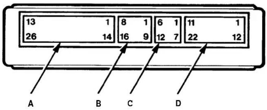
Fig.1 Control Module Connector Pins


Connections to the SLCM are detailed in the following table:
Connector A (26-way)
| Pin No. | Signal | Description | Comment |
| 01 | O/P | Deadlock (front right / rear left) | switch to ground200mA |
| 02 | O/P | Unlock driver's door | switch to ground200mA |
| 03 | |||
| 04 | |||
| 05 I/P | Vehiclespeed 7600 pulses | /mile | |
| 06 | O/P | Inclination alarm | |
| 07 | Intelligent sounder serial communications | ||
| 08 O/P | Memory seat 2 | switch to +12V for 500ms | |
| 09 | O/P | Visual warning switch to ground | |
| 10 | O/P | Secure mode status arm: | 200Hz square wave ± 5%disarm: 400Hz square wave ± 5%duration: 64ms |
| 11 | O/P | Trunk lid release relay | switch to ground |
| 12 | I/P | Power +12V battery | +12V power supply |
| 13 O/P | Sounder +ve | half of push pull network | |
| 14 | O/P | Deadlock (front left / rear right) | switch to ground (200mA) |
| 15 | O/P | Lock relay | switch to ground(200mA) |
| 16 | |||
| 17 | |||
| 18 | |||
| 19 | O/P | Alarm LED | switch to +12V (20mA) |
| 20 | O/P | Start inhibited | coded communication |
| 21 | O/P | Memory seat 1 | switch to +12V for 500ms |
| 22 | O/P | All close | switch to ground |
| 23 | O/P | Interior lights on | switch to ground for 80ms ± 5% |
| 24 | O/P | Horn relay | switch to ground (200ms) |
| 25 | I/P | Powerground | OV (nominal) |
| 26 | O/P | Sounder -ve | |
Connector B (16-way)
| 01 | |||
| 02 | Intrusion sensor (RH) | ground screen | |
| 03 | O /P | Intrusion sensor (RH) | 40kHz |
| 04 | I /P | Intrusion sensor (RH) | signal |
| 05 | O /P | Intrusion sensor (RH) | +8V |
| 06 | Ground | ||
| 07 | RF. ground | ||
| 08 | Diagnostic ISO K line | ||
| 09 | |||
| 10 | Intrusion sensor (LH) | ground | |
| 11 | O /P | Intrusion sensor (LH) | 40kHz |
| 12 | I /P | Intrusion sensor (LH) | signal |
| 13 | O /P | Intrusion sensor (LH) | +8V |
| 14 | Ground | ||
| 15 | I /P | RF. signal | |
| 16 | Diagnostic ISO L line | diagnostic link input |


Connector C (12-way)
| Pin No. | Signal | Description | Comment |
| 01 | I/P | Passenger door ajar | switch to ground |
| 02 | I/P | Trunk lid release external | switch to ground |
| 03 | I/P | Gearshift 'in-park' signal | not in-park = ground |
| 04 | I/P | Lock actuator status (RH) | switch to ground |
| 05 | I/P | Passenger door key unlock | switch to ground |
| 06 | I/P | Driver door key unlock | switch to ground |
| 07 | I/P | Driver door ajar | switch to ground |
| 08 | I/P | Ignition coil on (aux) | switch to ground |
| 09 | I/P | Transponder immobilization | data communications |
| 10 | I/P | Lock actuator status (LH) | switch to ground |
| 11 | I/P | Passenger door key lock | switch to ground |
| 12 | I/P | Driver door key lock | switch to ground |
Connector D (22-way)
| Pin No. | Signal | Description | Comment |
| 01 | O / P | Fuel filler flap lock | switch to ground 200mA |
| 02 | |||
| 03 | |||
| 04 | |||
| 05 | |||
| 06 | I / P | Trunk valet isolate switch | momentary switch to ground |
| 07 | I / P | Inclination alarm | |
| 08 | I / P | Trunk lid release (internal) | switch to ground |
| 09 | I / P | Hood open / ajar | switch to ground |
| 10 | I / P | Inertia switch | switch to ground |
| 11 | O / P | Transponder immobilization on | data communications |
| 12 | O / P | Memory seat remote indicator | switch to ground for 500ms |
| 13 | O / P | Headlight convenience | switch to ground for 25 seconds |
| 14 | |||
| 15 | |||
| 16 | |||
| 17 | I / P | Ignition on | switch to ground |
| 18 | I / P | Ignition key in | switch to ground |
| 19 | I / P | Central locking switch | switch to ground |
| 20 | I / P | Trunk lid ajar | switch to ground |
| 21 | I / P | Rear doors ajar | switch to ground |
| 22 | O / P | Unlock relay | switch to ground (200mA) |

A5.2.13 Siren
Located on theRH side at the front of the engine bay to provide audible alarm signals.
A5.2.14 Trunk lid release (external)
Located in trunk lid for conventional key access to luggage compartment.
A5.2.15 Trunk lid release (internal)
Located on fascia switchpack to allow lid release from driving position.
A5.2.16 Valet switch
Located in the central column compartment to allow securing of luggage compartment independently of other facilities.
A5
A5.3 GENERAL INFORMATION
The following information details the purpose and function of the system componentsirrespective of individual variant features.

A5.3.1 Locking:
Central locking
A traditional central locking application, such that when the driver's / passenger's door is locked/ unlocked using the door key all four doors lock/ unlock simultaneously.
Note: Locking operations will only take place when all doors are completely closed.
Remote central locking
Automatic locking/ unlocking, activated by the larger of the two key fob buttons.
Note: Locking operations will only take place when all doors are completely closed.
Deadlocking
A means of securing door lock so that they cannot be opened using the interior release mechanism, and arming the security sensing system, using the door key or remote transmitter
Two-stage unlocking
A key/ remote operated unlocking procedure which releases driver's door and fuel filler cap locks only, initially, and then releases all other doors and the luggage compartment locks.
Drive-away locks
Automatic locking of all doors, and luggage compartment (but not fuel filler cap), when gear selector is moved away from 'Park' and the ignition switch is in position II, providing all doors are closed.
Central lock/ unlock, all close
Automatic locking of all doors and luggage compartment by operation of the fascia mounted central locking switch. Continued switch operation causes closure of sliding roof and open windows.
Interior trunk lidrelease
Trunk lid unlocking from fascia mounted switch.
Flush sill buttons / intrusion override
Sill buttons fitted flush to door trim panel to prevent unauthorized override operation, buttons are latched in position when deadlock is applied.

A5.3.2 Security system
Base system
Provides standard vehicle arming, ie door ajar, actuator lockstatus, trunk lid or hood ajar and passenger door unlocking, does not include inclination or
Intrusion sensing
Detection of intrusion into the passenger compartment by removal or breakage of any glazed area, entry via any protected enclosure and unauthorized door opening detection.
Inclination (tilt)sensing
Detection of unauthorized jacking /towing.
Passive arming
Arming of the security system, excluding intrusion sensors, without audible confirmation.
Audible tones
Audible indication of driver error when attempting to arm the system, or on initiation of deadlocking.
Engine immobilization
Automatic immobilization of the engine crank facility whenever the ignition key is turned to position 0.
A5.3.3 Convenience
All close
Automatic closure of open windows and sliding roof by prolonged action of key, or remote fob transmitter after door locking.
Headlamp convenience
Automatic illumination of headlamps for driver convenience on operation of key fob button after locking sequence completed.
Remote trunk lid release
Automatic release of the trunk lid lock on operation of the smaller key fob button after door unlocking.
Trunk valet isolate
Independent locking of the trunk lid to eliminate unauthorized entry to the luggage compartment.
Driver seat memory select
Automatic recall of a memorized driving position on operation of the smaller key fob button.
Intrusion sensing override
Allows intrusion sensing to be disabled until the next disarm action.
A5.3.4 Alarms
There are eight possible alarm activation modes; driver's door, hood, ignition key in (ignition auxiliary position, ignition ON), inclination, inner door handle action (causing actuator status switches to operate), intrusion, passenger door and trunk.
Any of the above conditions occurring after the vehicle is fully armed will cause full alarm state.
Any of the above conditions, except door opening, occurring after the vehicle is fully armed and active disarming is selected will cause full alarm state. Door opening after active disarming selection will give a 30 second audible tick period before full alarm is entered.
Any of the above conditions occurring after the vehicle has been passively armed will give a 30 second audible tick period before full alarm is entered.
Activation of full alarm state causes sidelights, direction indicators, interior lights or headlamps to flash (dependant upon market variations), the security sounder to operate and the vehicle horns to operate (if programmed to doso).
An error tone is generated if active arming is selected with either hood or trunk open, or the transmitter is pressed with ignition key in auxiliary position.


A5.4 KEY FOB VARIATIONS
Due to the varying applications for different world markets, three types of key locking (local and remote) have been developed. The following tables detail these variations:
A5.4.1 European & UK markets (variant 1)
| DOOR LOCKING | ||||
| Action | Device operation | Function | ||
| Kev | R ote signal transmitter | |||
| Large button | Small button | |||
| Lock and arm (perimeter only) | Turn to lock position and release | 1st press | N / A | Locks all doors, trunk and fuel filler cap. Arms alarm system. |
| Lock, arm (perimeter only) and all-close | Turn to lock position and hold for 2 seconds | Continued holdof 1st press for 2 seconds | N / A | Locks all doors, trunk lid and fuel filler cap. Arms alarm system. Key only; closes open windows and sliding roof in 1.5 seconds. |
| Deadlock (perimeter, inclination, intrusion) and all-close | Turn to unlock, then lock within three seconds; hold in lock for all close | 2nd press and hold for 2 seconds | N / A | Deadlocks all doors, locks trunk lid and fuel filler cap and arms alarm system immediately. Closes windows and sliding roof after 1.5 seconds. |
| Headlamps ON for 25 seconds | N / A | 3rd press(1st press if button not operated within the last4 seconds) | N / A | Switches headlights on for driver convenience. |
Note: If key is turned to lock position with vehicle already locked / deadlocked, all - close will be activated.
| DOOR UNLOCKING | ||||
| Action | Device operation | Function | ||
| Jnlock | Turn to unlock position and release | N/A | 1st press | Unlocks doors, trunk lid (key only) and fuel filler cap. Disarms alarm system, except for 30 second audible tick, Turns on interior lights for 15 seconds. Remote button only; cancels trunk valet lock-out and recalls memorised driving position. |
| Trunk lid release | N/A | N/A | 2nd press (within 10 seconds of previous action) | Trunk lid release |
| Remote panic | N/A | N/A | 3 second press | Unlocks, disarms and enters full alarm state ie audible alarm (both sounder and horn) and visual alarm (flashing lights). |


A5.4.2 North American markets (variant 2)
| DOOR LOCKING | ||||
| Action | Device operation | Function | ||
| Key | Remote signal transmitter | |||
| Large button | Small button | |||
| Lock and arm (perimeter only) | Turn to lock position and release | 1st press | N/A | Locks all doors, trunk and fuel filler cap. Arms alarm system. |
| Lock, arm (perimeter only) and all-close | Turn to lock position and hold for 2 seconds | Continued hold of 1st press for 2 seconds | N/A | Locks all doors, trunk lid and fuel filler cap. Arms alarm system. Key only; closes open windows and sliding roof in 1.5 seconds. |
| Headlamps ON for 25 seconds press | N/A 2nd press | (1st if vehicle is locked and armed | N/A Switches | headlights on for driver convenience. |
| DOOR UNLOCKING | ||||
| Action | Device operation | Function | ||
| Unlock (driver's door only) | Turn to unlock position and release | N/A | 1st press | Unlocks driver's door, and fuel filler cap. Disarms alarm system. Turns on interior lights for 15 seconds. Remote button only; cancels trunk valet lock-out and recalls memorised driving position. |
| Unlock (all doors) | Either turn to unlock and hold for 2 seconds or perform a second unlock action | N/A | 2nd press | Unlocks all other doors, key only; unlocks trunk lid. |
| Trunk lid release | N/A | N/A | 3rd press (press to be within 10 seconds of previous action) | Trunk lid lock release |
| Remote panic | N/A | N/A | 3 second press | Unlocks, disarms and enters full alarm state ie audible alarm (both sounder and horn) and visual alarm (flashing lights). |

A5.4.3 Rest of the World (variant 3)
| DOOR LOCKING | ||||
| Action | Deviceoperation | Function | ||
| Key | Remote signal transmitter | |||
| Large button | Small button | |||
| Lock and arm (perimeter, inclination, intrusion) | Turn to lock position and release | 1st press | N / A | Locks all doors, trunk and fuel filler cap. Arms alarm system. |
| Lock, arm (perimeter, inclination, intrusion) and all-close | Turn to lock position and hold for2 seconds seconds | Continued hold of 1st press for 2 | N / A | Locks all doors, trunk lid and fuel filler cap. Arms alarm system. Key only; closes open windows and sliding roof in 1.5 seconds. |
| Headlamps ON for 25 seconds | N / A | 2nd press; within 10 seconds of first with vehicle unlocked, disarmed(1st press if vehicle is locked and armed) | N / A | Switches headlights on for driver convenience. |

| DOOR UNLOCKING | ||||
| Action | Device operation | Function | ||
| Unlock | Turn to unlock position and release | N/A | 1 st press | Unlocks all doors, trunk lid (key only) and fuel filler cap. Disarms alarm system.Turns on interior lights for 15 seconds. Remote button only; cancels trunk valet lock-out and recalls memorised driving position. |
| Trunk lid release | N/A | N/A | 2nd press (press to be within 10 seconds of previous action) | Trunk lid lock release. |
| Remote panic | N/A | N/A | 3 second press | Unlocks, disarms and enters full alarm state ie audible alarm (both sounder and horn) and visual alarm (flashing lights). |


Locking, unlocking and setting the vehicle alarm system is carried out by key or by radio frequency key-ring transmitter.
Operation of the system by key or key-ring transmitter will be described separately in this sub-section.
Key-ringtransmitter functions vary slightly between market variants. The action for each variant is described separately where appropriate
Note: Certain functions differ due to market variations. Differences will be detailed in the following instruction tables. The variants are defined as follows:
- Variant 1 - European and UK markets
- Variant 2 - North American markets
- Variant 3 - Rest of the World.
A5
A .5.1 Locking (key)
| Instruction | Variant 1 | Variant2 | Variant3 |
| rurn key to lock position and release. | Lock all doors, trunk lid, fuel filler cap and arm the alarm system (perimeter only). | .ock all doors, trunk lid, 'fuel filler cap and arm the alarm system. | Lock all doors, trunk lid, fuel filler cap and arm the alarm system (perimeter only) alarms. |
| rurn key to lock position, hold for2 seconds and re-ease. | Lock all doors, trunk lid, fuel filler cap. Arm the alarm system (perimeter only). Close open windows and sliding roof. | .ock all doors, trunk lid, 'uel filler cap. Arm the alarm system. Close open windows and sliding roof. | Lock all doors, trunk lid, fuel filler cap. Arm the alarm system (perimeter only). Close open windows and sliding roof. |
| rurn key to unlock position and then to lock position within 3 seconds. Hold in ock position for 2 seconds:o close windows and sliding roof. | Deadlock all doors, lock trunk lid and fuel filler cap. Arm the alarm system (perimeter, inclination and intrusion). Close open windows and sliding roof.Once deadlock is completed, the sounder gives one audible tone. | No feature | Deadlock all doors, lock trunk lid and fuel filler cap. Arm the alarm system (perimeter, inclination and intrusion). Close open windows and sliding roof.Once deadlock is completed, the sounder gives one audible tone.Note:No deadlock feature in Japanese market. |
A5.5.2 Unlocking (key)
| Instruction | Variant 1 | Variant2 | Variant3 |
| Turn key to unlock position and release. | Unlock all doors, trunk lid, fuel filler cap.On variant 1 unlocking with the key does not disarm the alarm system. An audible ticking indicates that the alarm will activate after 30 seconds unless the key is turned to position II in the ignition or the key-ring transmitter button (small) is pressed. | Unlock drivers door only, trunk lid, fuel filler cap.Disarm the alarm system.Switch on the interior light for 15 seconds. | Unlock all doors, trunk lid, fuel filler cap. Disarmthe alarm system. Switch on the interior light for 15 seconds. |
| turn key to unlock position and hold for 2 seconds. | No feature | Unlock all other doors and trunk lid. | No feature |


A5.5.3 Locking/ Unlocking(Key-ring Transmitter)
Each vehicle is supplied with two radio frequency transmitters, designed to be attached to the drivers key-ring. Key-ring transmitter1 is dedicated to driving position memory 1 and key-ring transmitter2 is dedicated to driving position memory 2.
The key-ring transmitter is activated by pointing towards the vehicle and pressing one of the two operating buttons; the large button locks the vehicle and arms the alarm system, whilst the small button unlocks the vehicle and disarms the alarm system. When either one of the buttons are pressed, an indicator light on the key-ring transmitter flashes; red for the large button, green for the small button.
If the ignition key is left in the ignition switch the following features will be inhibited:
- Alarm system
- Remote luggage compartment release.
If the ignition key is left in the ignition switch in position 1 the remote headlamp convenience feature will be inhibited.
Note: Locking is inhibited if any door is open or ajar.
A5
A5.5.4 Locking (Key-ring Transmitter)
| Instruction | Variant 1 | Variant 2 | Variant 3 |
| Press large button once. | Lock all doors, trunk lid,fuel filler cap and arm the alarm system (perimeter only).Direction indicators flash once. Warning light(central locking switches)flashes when vehicle secured. | Lock all doors, trunk lid,Fuel filler cap and arm the alarm system (perimeter,inclination and intrusion alarms).An audible signal will be heard and side lights willFlash once. Warning light(central locking switches)flashes when vehicle secured.Headlamps on for25 seconds if vehicle previously locked and armed. | Lock all doors, trunk lid,fuel filler cap and arm the alarm system (perimeter only).Direction indicators flash once. Warning light (central locking switches)flashes when vehicle secured.Headlamps on for25 seconds if vehicle previously locked and armed.Japanese Market Only:Lock all doors, trunk lid,fuel filler cap and arm the alarm system.Headlamps on for25 seconds if vehicle previously locked and armed. |
| Press large button again within 3 seconds of first press. | Deadlock all doors, Arm the alarm system (perimeter, inclination and intrusion). | Headlamps on for25 seconds. | Deadlock all doors, Arm the alarm system (perimeter, inclination and intrusion).Japanese Market Only:Headlamps on for25 seconds. |
| Press large button for third time within ten seconds of previous action. | Headlamps on for25 seconds.Note:The headlamps will also comeon if the large button is pressed whenever the vehicle is locked or deadlocked. | No Feature. | Headlamps on for25 seconds.Japanese Market Only;No Feature. |


A5.5.5 Unlocking (Key-ring Transmitter)

| Instruction | Variant 1 | Variant 2 | Variant 3 |
| Presssmall button once (vehicle locked and armed). | Unlocks all doors, trunk lid, fuel filler cap. Disarms the alarm system and switch on interior light for 15 seconds.Cancels luggage compartment valet lock-out, if set.Recalls the memory position of the driver's seat, steering column and door rear view mirrors.Two audible signals will be heard and the direction indicator will flash twice during the unlocking/ dis-arming process. | Unlocks drivers door only, trunk lid, fuel filler cap.Disarms the alarm system and switch on interior light for 15 seconds.Cancels luggage compartment valet lock-out, if set.Recalls the memory position of the driver's seat, steering column and door rear view mirrors.Two audible signals will be heard and the direction indicator will flash twice during the unlocking/ dis-arming process. | Unlocks all doors, trunk lid, fuel filler cap. Disarms the alarm system and switch on interior light for 15 seconds.Cancels luggage compartment valet lock-out, if set.Recalls the memory position of the driver's seat, steering column and door rear view mirrors.Two audible signals will be heard and the direction indicator will flash twice during the unlocking/ dis-arming process.Japanese Market Only:No audible or visual indication of unlocking/ dis-arming. |
| Presssmall button again. | Releases luggage compartment. Button must be pressed within ten seconds of first press. | Unlocks all passenger doors. | Releases luggage compartment. Button must be pressed within ten seconds offirst press. |
| Press small button again. | No feature | Releases luggage compartment. Button must be pressed within ten seconds of first Dress. | No feature |
Note: The sounder gives a short, high -pitched warble every time a button on the key-ring transmitter is pressed, whenever on of the following conditions is present:
The trunk lid or hood is not properly closed when an attempt to arm the security system is made.
- The ignition key is in the ignition switch
- If there is a failure within the security system.
A5.5.6 Panic Feature (Key -ring Transmitter Only)
When in or near the vehicle, the alarm can be set off to deter a would-be offender. This feature will also unlock the doors and fuelfiller flap. For this feature to operate, the ignition key must not be in position "I" or "II".
The panic alarm will sound for five times the normal full alarm period. The alarm can only be stopped by turning the ignition key to position'l' or 'll'. The key-ring transmitter can not be used to cancel the panic alarm.
To operate the panic alarm:
- Variants 1 and 3, press and hold the small button for 3 seconds.
- Variant 2, press and hold either the small or large buttons for 3 seconds.
Note: The panic alarm can be operated at any time during the locking or unlocking procedure, regardless of the state of the locking/ security system.

A5.5.7 Central Locking
Note: The following lock conditions are inhibited when any door is open or ajar.
The central locking switch is mounted on the facia. With the ignition switch in either position 'I' or 'II', press the central locking switch to lock all the doors and the luggage compartment, if they are unlocked.
Hold down the switch for 3 seconds to close any open windows or the sliding roof.
A further press on the central locking switch after 3 seconds will unlock the doors and the luggage compartment.
If the switch is pressed when ignition switch is not in position I or II, tilt and intrusion sensing will be disabled until the next arming action. The active indicator, mounted in the switch housing, will flash to confirm this action.
A5.5.8 Passive Arming
Passive arming is a dealer option on variants 1 and 3.
Passive arming of the vehicle, If the feature has been activated, takes place 30 seconds after the last closure of the doors, trunk lid, hood or sliding roof. For passive arming to take place the ignition switch must be in the 'OFF' position.
When passive arming occurs, the direction indicators flash once, the red warning light in the central locking switch lights for 2 seconds the flashes once the vehicle is armed.
Note: There is no audible indication when passive arming occurs.
To disarm a passively armed vehicle the ignition key or key-ring transmitter can be used as follows:
- Ignition key – Switch to position 'II'.
Key-ring transmitter - Refer to A5.3.5 Unlocking.

A5.5.9 Trunk Release
The trunk lid can be released in the following ways:
From the vehicle interior by pressing the trunk release switch mounted on the facia.
By using the ignition key in the trunk lid if the vehicle is disarmed. If not disarmed the alarm system will be activated and can be switched off by ignition key or key-ring transmitter.
○ Remotely (as part of the unlocking procedure) by the key-ring transmitter.
A5.5.10 Trunk Valet Isolate
A valet switch is located in the centre console compartment and is fitted on all variants.
The switch is provided to prevent unauthorized entry into the luggage compartment by a parking attendant by inhibiting the luggage compartment remote release switch.
The green headed valet key can be used to park and lock the vehicle but does not unlock the luggage compartment.

A5.5.11 Flush Sill Buttons
Variants 1 and 3 (except Japanese market) are fitted with flush sill buttons mounted in the door trim panel.
To lock the door from the interior press the sill button down, flush with the door trim panel. To unlock the door pull the door lever out.

A5.6 SYSTEM DIAGNOSTIC METHODS
The following information details diagnostic procedures for system fault identification using a Portable Diagnostic Unit (PDU).
PDU is designed and supplied by Jaguar Cars Ltd. to interrogate the electronic control circuitry of the various vehicle systems, diagnose fault conditions and indicate to the operator recorded faults and possible remedies. On initiation of diagnostic procedures PDU will display the model variant and control module type, a list of enabled functions can also be accessed. Ensure that this information is correct for the vehicle under test, ie that the correct module is fitted and all appropriate options are enabled.
Detailed information on testing using PDU is detailed in the support documentation supplied with the unit.
A5
A5.7 SYSTEM TESTING
The following information details: the procedures for a completesystem test to identify and locatepossiblefault conditions. Where faulty operation is identified refer to Diagnostic Sub-Routines for possible causes and remedies.
Locking, unlocking and setting the vehicle alarm system is carried out by key or by radio frequency key-ring transmitter.
Note: Ensure all doors are fully closed before initiating lock procedures.
Key-ringtransmitter functions vary slightly between marketvariants. The action for each variant is described separately where appropriate
Note: Certain functions differ due to market variations. Differences will be detailed in the following instruction tables. The variants are defined as follows:
- Variant 1 - European and UK markets.
- Variant 2 - North American markets.
- Variant 3 – Rest of the World.
A5.7.1 Locking (key)
| *instruction | Variant 1 | Variant 2 | Variant3 |
| Turn key to lock position and release. imeter | Check that all doors, trunk lid and fuelfiller cap lock and that the alarm system (per-only).arms. | ||
| Turn key to lock position, hold for 2 seconds and re-ease. | Check that all doors, trunk lid and fuel filler cap lock,.the alarm system (perimeter only) arms and all open windows and sliding roof close within 1.5 seconds. | ||
| Turn key to unlock position and then to lock position within 3 seconds. Hold in ock position for 2 seconds to close windows and sliding roof. | Check all doors are dead-locked and trunk lid and fuel filler cap are locked. Check alarm system (perimeter, inclination and intrusion) arms and all open windows and sliding roof close within 1.5 seconds.Ensure that once deadlock ing is completed, the sounder gives one audible tone. | No feature | Check all doors are dead-locked and trunk lid and fuel filler cap are locked. Check alarm system (perimeter, inclination and intrusion) arms and all open windows and sliding roof close within 1.5 seconds.Ensure that once deadlock ing is completed, the sounder gives one audible tone.Note:No deadlock feature in Japanese market. |
A5.7.2 Unlocking (key)
| Instruction Variant | 1 | Variant 2 | variant 3 |
| Turn key to unlock position and release. | Check all doors, trunk lid and fuel filler cap unlock. | Check drivers door and fuel filler cap unlock.Check that the alarm system disarms and the interior light illuminates for 15 seconds. | Check all doors, trunk lid and fuel filler cap. Check that the alarm system disarms and the interior light illuminates for 15 seconds. |
| with the key does not disarm the alarm system. An audible ticking indicates that the alarm will activate after 30 seconds unless the key is turned to positionII in the ignition or the key-ring transmitter button (small) is pressed. | |||
| Turn key to unlock position and hold for 2 seconds. | No feature | Check all passenger doors and trunk lid lock. | No feature |

A5


A5.7.3 Locking/ Unlocking(Key-ring Transmitter)
Each vehicle is supplied with two radio frequency transmitters, designed to be attached to the drivers key-ring. Key-ring transmitter 1 is dedicated to driving position memory 1 and key-ring transmitter 2 is dedicated to driving position memory 2.
The key-ring transmitter is activated by pointing ittowards the vehicle and pressing one of the two operating buttons; the large button locks the vehicle and arms the alarm system, whilst the small button unlocks the vehicle and disarms the alarm system. When either one of the buttons are pressed, an indicator light on the key-ring transmitter flashes; red for the large button, green for the small button.
If the ignition key is left in the ignition switch the following features will be inhibited:
Alarm system
- Remote luggage compartment release.
If the ignition key is left in the ignition switch in position 1 the remote headlamp convenience feature will be inhibited.
A5.7.4 locking (Key-ring Transmitter)
| nstruction | Variant 1 | Variant 2 | Variant 3 |
| Press large button once. | Check all doors, trunk lid and fuel filler cap lock and the alarm system (perimeter only) arms.Ensure direction indicators flash once and the security active indicator flashes when vehicle secured.Check that headlamps are illuminated for 25 seconds if vehicle was previously locked and armed and but ton has not been pressed within 4 seconds. | Check all doors, trunk lid and fuel filler cap lock and the alarm system arms.Ensure that an audible signal is heard, side lights flash once. and security active indicator flashes when vehicle secured.Check that headlamps are illuminated for 25 seconds if vehicle was previously locked and armed. | Check all doors, trunk lid and fuel filler cap lock and the alarm system (perimeter only) arms.Ensure direction indicators flash once. and security active indicator flashes when vehicle secured.Check that headlamps are illuminated for 25 seconds if vehicle was previously locked and armed.Japanese Market Only:Check all doors, trunk lid and fuel filler cap lock and the alarm system arms.Check that headlamps illuminate for 25 seconds if vehicle was previously locked and armed. |
| Presslarge button again within 3 seconds of first press. | Check all doors are dead- locked and the alarm sys- tem (perimeter, inclination and intrusion) is armed. | Check headlamps illumi - nate for 25 seconds. | Check all doors are dead locked and the alarmsys- tem (perimeter, inclination and intrusion) is armed.Japanese Marked Only:Check headlamps illumi - nate for 25 seconds. |
| Presslarge button for third time within ten seconds of previous action. | Check headlamps illumi - nate for 25 seconds.Note:The headlamps will also illuminate if the large but ton is pressed whenever the vehicle is lockedor deadlocked. | No Feature. | Check headlamps illumi - nate for 25 seconds.Japanese Marked Only:No Feature. |


A5.7.5 Unlocking (Key-ring Transmitter)
| Instruction | Variant 1 | Variant2 | Variant3 |
| Press small button once (vehicle locked andarmed). | Check all doors, trunk lid and fuel filler cap unlock Check that the alarm system dis-arms and the interior light illuminates for 15 seconds.Check luggage compartment valetlock-out is cancelled, if set.Ensure the memory position of the driver's seat, steering column and door rear view mirrors is restored.Check that two audible signals are heard and the direction indicator flashes twice during the unlocking/ disarming process. | ||
| IPress small button again | Check luggage compaport-ment released when but-ton pressed within ten sec onds of first press. | Check all passenger doors unlocked. | Japanese Market Only:No audible or visual in-dication of unlocking/dis-arming. |
| Press small button again | No feature | Check luggage compaport-ment released when but-ton pressed within 10 sec-onds of second press. | No feature. |
Check that the sounder gives a short, high-pitched warble every time a button on the key-ring transmitter is pressed, whenever one of the following conditions is present:
The trunk lid or hood is not properly closed when an attempt to arm the security system is made.
- The ignition key is in the ignition switch
○ If there is a failure within the security system.
A5.7.6 Panic Feature (Key-ring Transmitter Only)
Ensure the ignition key is not in position 'I' or 'II' and check panic alarm as follows.
To operate the panic alarm:
○ Variants 1 and 3, press and hold the small button for 3 seconds.
○ Variant 2, press and hold either the small or large buttons for 3 seconds.
Ensure that the panic alarm sounds for five times the normal full alarm period and the alarm can only be stopped by turning the ignition key to position 'I' or 'II' ie the key-ring transmitter can not be used to cancel the panic alarm. Check that the alarm unlocks the doors and fuel filler flap.
Note: The panic alarm can be operated at any time during the locking or unlocking procedure, regardless of the state of the locking / security system.

A5.7.7 Central Locking
Note: Ensure all doors are fully closed before commencing lock operations.
With the ignition switch in either position "I" or "II", press the central locking switch and check that all the doors and the luggage compartment lock, if they are unlocked.
Hold down the switch for 3 seconds and check any open windows or the sliding roof close, if open.
Check that a further press on the central locking switch after 3 seconds will unlock the doors and the luggage compartment.
If the switch is pressed when ignition switch is not in position I or II, tilt and intrusion sensing will be disabled until the next arming action. The active indicator, mounted in the switch housing, will flash to confirm this action.
To disarm a passively armed vehicle the ignition key or key-ring transmitter can be used as follows:
- Ignition key- Switch to position'll'.
Key-ring transmitter- Refer to A5.3.5 Unlocking.
A5.7.8 Passive Arming
Passive arming is a dealer option on variants 1 and 3 only.
With the ignition switch in the OFF position, check that passive arming of the vehicle takes place30 seconds after the last closure of the doors, trunk lid, hood or sliding roof.
Ensure that when passive arming occurs, the direction indicators flash once and the security active indicator in the central locking switch lights for 2 seconds then flashes once when vehicle arming is complete.
Note: There is no audible indication when passive arming occurs.
A5.7.9 Trunk Release
Check that the the trunk lid can be released in the following ways:
- From the vehicle interior by pressing the trunk release switch mounted on the facia.
By using the ignition key in the trunk lid if the vehicle is disarmed. If not disarmed the alarm system will be activated and can be switched off by ignition key or key-ring transmitter. - Remotely (as part of the unlocking procedure) by the key-ring transmitter.
A5.7.10 Trunk Valet Isolate
Check that valet switch operation prevents unauthorized entry into the luggage compartment by inhibiting the luggage compartment remote releaseswitch and the green headed valet key can be used to park and lock the vehicle but does not unlock the luggage compartment.
A5.7.11 Flush Sill Buttons
Variants 1 and 3 (except Japanese market) are fitted with flush sill buttons mounted in the door trim panel. Check button operation as follows:
To lock the door from the interior press the sill button down, flush with the door trim panel. To unlock the door pull the door lever out.
A5.8 DIAGNOSTIC SUB-ROUTINES
The following information details possible remedies to faults identified in the system during the system test. For detailed testing of individual components refer to section A5.9, Pin Point Tests.
Fault: System will not lock / and arm
| Possible causes: | 1. | Transmitter battery faulty (remote operation only) |
| 2. | Rear screen aerial cable damaged / disconnected (remote operation only). | |
| 3. | No power supply to SLCM. | |
| 4. | Wiring harness or connectors faulty. |
| Remedy: | 1. | Renew battery, refer to section A58. |
| 2. | Identify and repair aerial cable fault. | |
| 3. | Check fuse F4 in trunk fuse box. | |
| 4. | Check harness and connectors from SLCM. Repair or renew as necessary. |
A5
Fault: All Close facility only inoperative or faulty
| Possible causes: | 1. | Faulty components in sliding roof or window systems. |
| 2. | Damaged harness wiring between SLCM and Sliding Roof Control Module (SRCM) and Body Processor Unit (BPU). |
| Remedy: | 1. | Refer to Section 15.7 Closures. |
| 2. | Examine and repair or renew faulty harness. |
Fault: Door locking/ unlocking facility inoperative or faulty
| Possible causes: | 1. | No power supply to lock relays. |
| 2. | Door lock/ unlock relays faulty. | |
| 3. | Door actuators faulty. | |
| 4. | Keylock switches faulty. | |
| 5. | Deadlock circuitry faulty. | |
| 6. | Wiring harness or connectors faulty. |
| Remedy: | 1. | Check fuse F1 in RH 'A' post base fusebox. |
| 2. | Renew faulty relay. | |
| 3. | Renew door lock assembly complete. | |
| 4. | Renew door lock assembly complete. | |
| 5. | See Deadlock fault Sub-Routine. | |
| 6. | Examine and repair or renew faulty harness |
Fault: Deadlocking facility inoperative or faulty (not NAS)
| Possible causes: | 1. | No power supply to deadlock relays. |
| 2. | Deadlock relays faulty. | |
| 3. | Deadlock status micro-switch faulty. |
| Remedy: | 1. | Check fuse F1 in RH'A' post base fusebox. |
| 2. | Renew faulty relay. | |
| 3. | Renew doorlock assembly complete. |

Fault: Intrusion sensing inoperative
Possible causes: 1. Faulty sensor. 2. Harness wiring or connectors faulty.
Remedy: 1. Renew sensor. 2. Examine and repair or renew faulty harness.
Fault: Inclination sensing inoperative
Possible causes: 1. Faulty sensor. 2. Harness wiring or connectors faulty.
Remedy: 1. Renew sensor. 2. Examine and repair or renew faulty harness.
Fault: Fuel filler cap locking/ unlocking faulty
Possible causes: 1. No power to actuator relay. 2. Wiring harness or connectors faulty 3. Relay faulty 4. Actuator faulty.
Remedy: 1. Check fuse F1 in RH 'A' post fuse box. 2. Examine and repair or renew faulty harness. 3. Renew relay. 4. Renew actuator.
Fault: Panicfeature inoperative
Possible causes: 1. Transmitter battery inoperative. 2. Rear screen aerial cable damaged/ disconnected.
Remedy: 1. Renew battery. 2. Identify and repair aerial fault.
Fault: Central locking switch inoperative
Possible causes: 1. Harness wiring or connectors faulty. 2. Switch faulty.
Remedy: 1. Examine and repair or renew damaged harness. 2. Renew switch.

Fault Trunk lid locking / unlocking faulty
Possible causes: 1. No power to actuator relay.
2. Wiring harness or connectors faulty
3. Relay faulty
4. Actuator faulty.
5. Switch faulty.
Remedy: 1. Check fuse F8 in trunk fuse box.
-
Examine and repair or renew faulty harness.
-
Renew relay.
-
Renew actuator.
-
Renew switch.
-
Examine and repair or renew faulty harness.
- Renew relay.
- Renew actuator.
- Renew switch.
A5
Fault Valet isolate facility inoperative
Possible causes: 1. Faulty switch
2. Harness wiring or connectors faulty.
Remedy: 1. Renew switch.
- Examine and repair or renew faulty harness.
Fault Sill buttons inoperative
Possible causes: 1. Mechanical failure
2. Door microswitch faulty.
Remedy: 1. Refer to VSM.
- Renew door lock assembly complete.
Fault Memory position selection inoperative
Possible causes: 1. Transmitter battery inoperative.
2. Rear screen aerial cable damaged / disconnected.
3. Memory switch pack faulty
2. Rear screen aerial cable damaged / disconnected.
3. Memory switch pack faulty
Remedy: 1. Renew battery.
-
Identify and repair aerial cable fault.
-
Refer to Section 15.4.
Note: For door, hood and trunk ajar fault diagnosis refer to Section 15.2


A5.9 PIN-POINT TESTS
The following information details test procedures to identify specific component faults.
The table below provides a key to items identified on the following schematic diagrams.

| Item No. | Description | Item No. | Description |
| 1 | Security / Locking Control Module | 21 | Hood switch |
| 2 | Central locking switch | 22 | LH Engine bay fuse-box |
| 3 | Front passenger door ajar switch | 23 | Horn relay |
| 4 | RH rear passengerdoor ajar switch | 24 | Horn unit LH |
| 5 | LH rear passengerdoor ajar switch | 25 | Horn unit RH |
| 6 | Driver's door ajar switch | 26 | Horn switches |
| 7 | Driver's door lock switch | 27 | Inclination sensor |
| 8 | Passenger's door lock switch | 28 | Intrusion sensor LH |
| 9 | Driver's door unlock relay (NAS only) | 29 | Intrusion sensor RH |
| 10 | Non -deadlock shorting links (NAS only) | 30 | Passengerdoor key barrel switch |
| 11 | Front left / rear right deadlock relay | 31 | Driver's door key barrel switch |
| 12 | Front right / rear left deadlock relay | 32 | Reader exciter module |
| 13 | Door lock relay | 33 | Reader exciter coil |
| 14 | Door unlock relay | 34 | Trunk fuse -box |
| 15 | LH Rear door actuator and switch | 35 | Security active indicator |
| 16 | RH Rear door actuator and switch | 36 | Security sounder |
| 17 | Front door actuator lock / deadlock status switches | 37 | Trunk release relay |
| 18 | Driver's door actuator lock / deadlock status switches | 38 | Trunk release actuator |
| 19 | Driver's door unlock shorting link | 39 | Trunk release switch (fascia) |
| 20 | RH 'A' post base fuse -box | 40 | Trunk release switch |
| 41 | Val et switch |


A5.9.1 Central locking switch
- Check continuity from 22-way multi -plug pin 19 to ground, open circuit should be recorded.
- Operate switch and check that short circuit to ground is now present.
- Check wiring continuity from 22-way multi-plug pin 19 to switch connector pin3.
- Check wiring continuity from switch connector pin 1 to ground.
Note: If switch is faulty the whole clock module must be renewed; refer to sub-section 15.9.10.
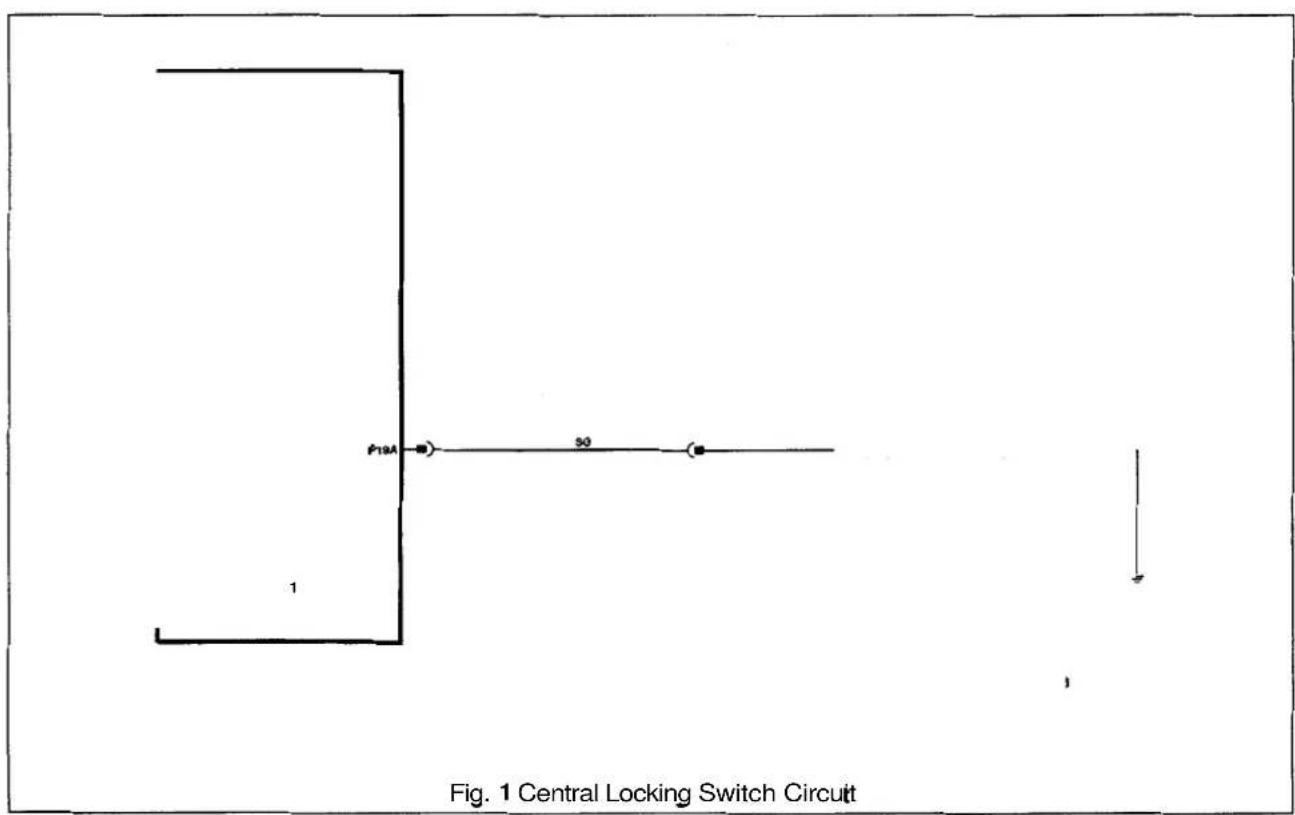
A5
A5.9.2 Door ajar switches
- Close all four doors and turn ignition to ON.
- Open each door in turn, checking that instrument pack indicator lamp illuminates at every opening action.
- On identification of non-illumination check continuity across suspect door switch, door closed - switch open circuit, door open switch short circuit.
- If switches test correctly check wiring continuity between SLCM connector and switches, then to ground as detailed below

| Door | SLCM | Switch | Ground |
| Driver's Pin | 07, 12-way | Pin 06 | Pin 07 |
| Passenger's Pin 01, 16 (front) | -way | Pin 06 Pin 06 | |
| Passenger's (rear) Pin | 21, 22-way Pin | 05 | Pin 06 |
![graph TD A["1"] --> B["P01C"] B --> C["UO"] B --> D["P18"] D --> E["P16 GW P06"] E --> F["P07 B"] A --> G["P21D"] G --> H["P"] G --> I["P18"] I --> J["P16 G P05"] J --> K["P06 B"] A --> L["P07C"] L --> M["P06"] L --> N["P09 G P08"] N --> O["P07 B"] style A fill:#f9f,stroke:#333 style B fill:#ccf,str…](/content/2026/06/1254020/images/b1fe9cf10fcd98dfe2a70b0a101fdb6b430d3206035787c5492ae6c95b24a7d3.jpg)
Fig. 1 Door Ajar Switches Circuit

A5.9.3 Door locks
- Check harness wiring continuity between multi-plug 12-way connector pins 10 (driver's side) and 4 (passenger's side) to respective door lock connector pin 8. Ensure secure ground connection from each lock connector pin 9.
- Test continuity across switch pins, reading should be open circuit with door unlocked, short circuit with door locked.


Fig. 1 Door Locks Circuit

3
A5.9.4 Door lock actuators and switch
- Examine fuse F1 in right hand 'A' post base fusebox, if blown determine reason for rupture and renew.
- Check continuity of harness wiring as shown on Fig. 1 below. Ensure secure ground connection from lock/ unlock and deadlock (not N.A.S.) relay pins4 and 9.
- Remove the left hand rear seat hell board, gaining access to lock/ unlock and deadlock (not N.A.S.) relays. Operate lock/ unlock and deadlock checking for audible relay operation. renew suspect relays.
- Release door lock and measure resistance between actuator unit pins 2 and 3, a value of approximately 8Ω should be recorded. Operate door lock and check that circuit between pins 2 and 3 is opened. Resistance across pins 1 and 3 should now be approximately 88.


*1 N.A.S. only
*2 Not N.A.S.
A5.9.5 Hood Switch
- Check continuity between SLCM 22-way connector pin 9 and ground. With hood closed open circuit should be recorded, with hood open short circuit to ground should be recorded.
- Check wiring continuity from pin 9 to switch connector pin 1, and from switch connector pin 2 to ground.
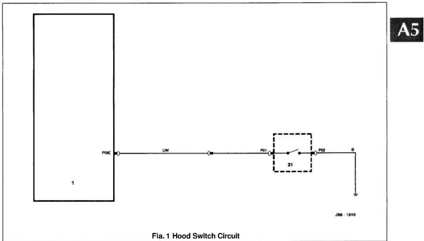
A5.9.6 Horns
- Check fuses F10 and F14 in LH engine bay fuse box; if blown determine reason for rupture and renew.
- Check wiring harness continuity from multi-plug 26-way connector pin 24 to relay unit connector pin 6 and column switchgear connector pin16. Ensure secure ground connection from column switchgear connector pin7.
Check wiring harness continuity from fuse connector pins 7 and 8 to LH and RH horn respectively. Ensure secure ground connection from both horn units.
Ensure that +12V (nominal) is present at the relay connector pin.
Operate horn switches and check that +12V (nominal) is present at the two fuse connector pins and at speaker connector pin 44 (both units).
Check resistance across speaker unit pins; a value of approximately 2Ω should be recorded.

Fig. 1 Horn Unit and Relay Circuit

A5.9.7 Inclination sensor
- Check harness wiring from multi-plug 26-way connector pin 6 to sensor connector pin 2.
- Check harness wiring from multi-plug 22-way connector pin 7 to sensor connector pin 1.
- Check harness wiring continuity from sensor connector pin 5 to ground.
- Removetrim to gain access to sensor and loosen fixings. Lock and arm the vehicle (an error beep will sound indicating boot open but alarm will still set), then tilt the sensor a minimum of 15° away from horizontal checking that the alarm is activated.
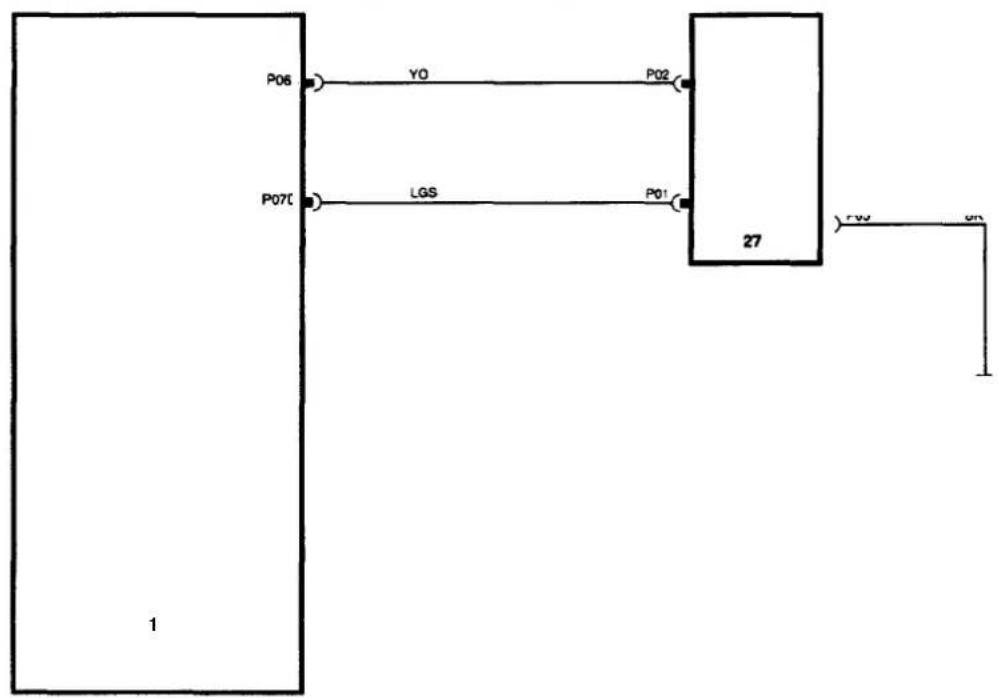
- Check harness wiring continuity as shown below:
| SLCM connector | Sensor connector | Function |
| Left-hand side sensor | ||
| pin 10 | pin 2 | ground |
| pin 11 | pin 4 | 40kHz |
| pin 12 | pin 5 | I/P |
| pin 13 | pin 3 | +av |
| Right-hand side sensor | ||
| pin 2 | pin 2 | ground |
| pin 3 | pin 4 | 40kHz |
| pin 4 | pin 1 | I/P |
| pin 5 | pin 3 | +av |
- Lock and arm the vehicle while sat inside; wait 15 seconds, then attempt to cover either sensor area with the palm of the hand. Check that sensor detects movement and activates alarm. Repeattest for second sensor.

Fig. 1 Intrusion Sensor Circuit
J86·1013
A5.9.9 Key barrel switches
- Check harness wiring continuity as follows:
SLCM 16-way connector Switch Function
Driver's side
pin 6
pin 11 unlock signal
pin 12 pin
10 lock signal
pin 12 ground
Passenger's side
pin 5
pin 11 unlock signal
pin 10
pin 10
lock signal
pin 12 ground
- Check continuity from switch pin 10 to ground with door locked, and from switch pin 11 to ground with door unlocked.

Fig. 1 Key Barrel Switches
A5.9.10 Reader exciter coil and module
- Check fuse F4 in trunk fuse box, if blown determine reason for rupture and renew.
- Check harness wiring continuity as follows:
| SLCM connector | Module connector | Coil connector | Function |
| pin 6 (16-way) pin 19 | - | ground | |
| pin 9 (12-way) pin | 06 | - | data code |
| pin 11(22-way) | pin 08 | - | immobilization on |
| - | pin 1 pin | 10 | coil terminal2 |
| - | pin 9 pin 11 | coil terminal 1 | |
| - | pin 10 | - | +12V |
| - | pin 20 | - | ground |
- Measure continuity between coil pins.
![graph TD A["1"] --> B["P06B"] A --> C["P09C"] A --> D["P11D"] A --> E["P04A"] B --> F["SY"] B --> G["SW"] C --> H["SR"] C --> I["P08"] D --> J["P08"] D --> K["P09"] E --> L["5U"] F --> M["32"] G --> M H --> M I --> M J --> M K --> M L --> M M --> N["NU"] M --> O["RG"] M --> P["RU"] M --> Q["B"] N --…](/content/2026/06/1254020/images/ce5deb9d400c3559b573ea5ffc12f87e9cb55e7f0c40d368d49db967a4c40d3c.jpg)
Fig. 1 Reader Exciter Coil and Module Circuit
A5.9.11 Security active indicator
- Check wiring continuity from multi-plug 26-way connector pin 19 to central locking switch connector pin 13. Ensure secure ground at switch connector pin 16.
Note: If indicator is faulty the whole clock module must be renewed, refer to sub-section 15.9.10.

Fig. 1 Security Active Indicator Circuit
A5
A5.9.12 Sounder
- Check harness wiring continuity from multi-plug 26-way connector pins 13 and 26 to sounder connector pins 2 and 1 respectively.
- Measure resistance across sounder pins; a value of 8Ω should be recorded.
A5

J86 - 1917
Fig. 1 Security Sounder Circuit
A5.9.13 Trunk lid release actuator and relay
- Check fuse F8 in trunkfusebox; if blown determine reason for rupture and renew.
- Check harness wiring continuity between trunk fuse box connector pin 7 and relay pins 1 and 5.
- Check harness wiring continuity to ground from relay connector pin 4 and actuator connector pin 1.
- Check harness wiring from multi-plug 26-way connector pin 11 to relay connector pin2.
- Check harness wiring continuity from relay connector pin 3 to actuator connector pin 2.
- Measure resistance across relay connections 1 and 2; a value of 85Q should be recorded.
- Measure resistance across actuator pins; a value in the region of 20–30Q should be recorded.
A5
![graph TD A["Power Supply"] --> B["P01"] A --> C["P02"] A --> D["P03"] A --> E["P04"] A --> F["P05"] A --> G["P06"] A --> H["P07"] A --> I["P08"] A --> J["P09"] A --> K["P10"] A --> L["P11A"] M["+12V"] --> N["F8"] N --> O["34 Pin"] O --> P["B"] Q["YS"] --> R["37 Pin"] S["NS"] --> T["37 Pin"] U["Groun…](/content/2026/06/1254020/images/cb02df6ffd2d4d7f2a18de28848e19b787ba7efa90e49007bf8dc7dd2c6b8bff.jpg)
J86-1918
Fig. 1 Trunk Lid Actuator and Relay Circuit
A5.9.14 Trunk lid release switches
- Check harness wiring continuity from multi-plug 12-way connector pin 2 to external trunk release switch connector pin 10. Ensure secure ground connection from switch pin 5.
- Check harness wiring continuity from multi-plug 22-way connector pin 8 to internal trunk release switch connector pin 1. Ensure secure ground connection from switch pin 2.
- Test continuity across switch pins, operate switch and ensure short circuit occurs.
A5

J86·1919
Fig. 1 Trunk Lid Release Switches

A5.9.15 Valetswitch
- Check harness wiring continuity from multi-plug 22-way connector pin 6 to valet switch connector pin 1.
- Test continuity across switch connections, operate switch and ensure short circuit occurs.

A5


A5.10 INCLINATION SENSOR - RENEW
SRO 86.52.21
■ Remove the trunk floor carpet.
■ Remove the trunk front liner.
■ Removethe trunk seal retainer. See SRO76.19.44, Section 13.
■ Removethe trunk side liner.
■ Disconnect the inclination sensor multiplug. (1 Fig. 1).
■ Undo and remove the sensor mounting bracket securing nuts (2 Fig. 1). Remove the sensor (3 Fig. 1) complete with mounting bracket (4 Fig. 1).
■ Displace the mounting bracket retaining tang and remove the sensor.
■ Fitting a new inclination sensor is the reverse of the removal procedure.

Fig. 1
A5.11 SECURITY & LOCKING CONTROL MODULE (SLCM)- RENEW
SRO 86.52.01
■ Open the trunk and remove the battery cover.
■ Disconnect the battery ground lead.
■ Remove the trunk floor carpet.
■ Remove the trunk front liner.
- Removethe trunk seal retainer. See SRO76.19.44, Section 13.
■ Remove the trunk side liner.
■ Undo and remove the inclination sensor securing nuts (2 Fig. 1) and displace the sensor (3 Fig. 1) to gain access to the SLCM (1 Fig. 2).
■ Undo and removethe SLCM securing nuts (5 Fig. 1).
- Displace the SLCM. Identify the SLCM multi-plugs (2 Fig. 2) for subsequent reconnection. Disconnect the mult-plugs and remove the SLCM.
- Fitting a new SLCM is the reverse of the removal procedure. Make sure that the multi-plugs are reconnected as removed from the old SLCM.
Note: The arrows on Fig. 2 show the position of the mounting bolts and mounting holes.


A5.12 INTRUSION SENSOR - RENEW
SRO 86.52.20
■ Carefully displace the intrusion sensor from the headlining.
Note: View 1 (Fig. 1) shows a vehicle fitted with a sliding roof. View2 (Fig. 1) shows a vehicle without a sliding roof.
■ Disconnect the multi-plug and remove the intrusion sensor.
■ Reconnect multi -plug to a new intrusion sensor.
- Locate the intrusion sensor securing studs and carefully push into the headlining. Make sure the intrusion sensor is fully seated.

A5
A5.13 HAND TRANSMITTER BATTERY - RENEW
SRO 86.52.28
■ Remove the hand transmitter rear cover(1 Fig. 2).
- Remove batteries (2 Fig. 2) and discard.
- Fit two new batteries making sure the polarity is as shown in Fig2.
■ Fit and fully seat the transmitter rear cover.

A5.14 VALET SWITCH - RENM
SRO 86.52.08
- Open the centre console compartment and carefully displace the valet switch.
■ Disconnect the harness connector and remove the valet switch.
■ Fitting a new valet switch is the reverse of the removal procedure. Make sure the switch is fully seated.


A5.15 SECURITY SIREN (12 CYL)- RENEW
SRO 86.52.03
- Open the trunk and remove the battery cover.
■ Disconnect the battery ground lead. - Open the hood and remove the headlamp / relay cover. See SRO 76.11.22, Section 13.
■ Remove the RH air cleaner element. See SRO 19.10.11, Section 5.2.
■ Remove the RH air cleaner assembly. See SRO 19.10.02, Section 5.2. - Identify the RH forward harness relays (1 Fig. 1) for subsequent refitting. Remove the relays and relay bases from the mounting bracket.
■ Disconnect the siren harness multi - plug(2 Fig. 1). - Reposition the side harness (3 Fig. 1) to gain access to the siren securing bolts.
■ Undo the siren securing bolts (1 Fig. 2) and remove the siren (2 Fig. 2).
Note: The siren securing bolts remain captive.
■ Remove the captive washers and the siren securing bolts.
■ Fit the siren securing bolts to a new siren.
■ Fit and fully seat the captive washers.
■ Align the siren securing bolts to the vehicle chassis. Tighten the siren securing bolts.
Refitting the remaining components is the reverse of the removal procedure.
A5.16 SECURITY SIREN (6 CYL) - RENEW
SRO 8652.03
■ Open the trunk and remove the battery cover.
■ Disconnect the battery ground lead.
■ Open the hood and remove the headlamp / relay cover. See SRO 76.11.22, Section 13.
- Identify the RH forward harness relays for subsequent refitting. Removethe relays and relay bases from the mounting bracket.
■ Disconnect the siren harness multi-plug.
■ Reposition the side harness to gain access to the siren securing bolts.
■ Undo the siren securing bolts and remove the siren.
Note: The siren securing bolts remain captive.
- Remove the captive washers and the siren securing bolts.
■ Fit the siren securing bolts to a new siren.
■ Fit and fully seat the captive washers. - Align the siren securing bolts to the vehicle chassis. Tighten the siren securing bolts.
Refitting the remaining components is the reverse of the removal procedure.


A5.17 FRONT DOORLOCK ASSEMBLY - RENEW
SRO 86.25.45
- Remove the veneer trim pad. See Section 13 of the VSM.
■ Remove the upper trim pad. See Section 13 of the VSM. - Remove the lower trim pad. See Section 13 of the VSM.
- Using a suitable plastic knife, cut through the weather-shield to door sealant and pull back the weathershield (1 Fig. 1) for access to the door lock assembly.
■ Disconnect the door handle link rod(2 Fig. 1).
■ Disconnect the door sill button link rod (3 Fig. 1).
■ Disconnect the key barrel link rod (4 Fig. 1). - Displace and reposition the door lock assembly multi-plug from the mounting bracket and disconnect.
- Undo and remove the lower securing bolt(5 Fig. 1) from the glass frame.
■ Undo and remove the door lock assembly securing bolts (6Fig. 1).
■ Displace and reposition the glass frame.
■ Displace and reposition the door lock assembly (7 Fig. 1). - Displace and remove the edge clip from the door handle release cable (8 Fig. 1).
■ Displace and reposition the door handle release cable from the abutments.
■ Displace and remove the door lock assembly.
■ Position the new door lock assembly to the door.
■ Position and fit door handle release cable to abutments.
■ Fit and fully seat the cable retaining edge clip.
■ Fit and tighten the door lock assembly securing bolts.
■ Reposition glass frame. Fit and tighten frame securing bolt.
■ Connect the multi-plug and fit to the mounting bracket.
■ Connect the key barrel link rod.
■ Connect the door sill button link rod.
■ Connect the door handle link rod.
■ Reposition the weathershield to the door. Using a suitable tool, apply pressure to the weathershield edge to ensure adhesion to the door.
■ Refit the lower trim pad, upper trim pad and the veneer trim pad.

A5


A5.18 REAR DOOR LOCK ASSEMBLY - RENEW
SRO 86.25.47
■ Remove the veneer trim pad. See Section 13 of the VSM.
■ Remove the upper trim pad. See Section 13 of the VSM.
■ Remove the lower trim pad. See Section 13 of the VSM.
- Using a suitable plastic knife, cut through the weathershield to door sealant and pull back the weathershield for access to the door lock assembly.
- Cut and remove the securing tie-wrap from the door lock assembly harness multi-plug.
- Displace and reposition the door lock assembly multiplug from the mounting bracket and disconnect.
- Disconnect the door handle link rod.
■ Disconnect and remove the door sill button link rod.
■ Undo and remove the door lock assembly securing bolts.
■ Undo and remove the lower securing bolt from the glass frame.
- Displace and reposition the door lock assembly into the bottom of the door.
- Displace and remove the edge clip from the door handle release cable.
■ Displace and reposition the door handle release cable.
- Displace and remove the door lock assembly.
A5.19 TRUNKLIDLOCKACTUATOR -RENEW
SRO 86.25.49
■ Open the trunk lid.
■ Remove the luggage compartment lamp assembly. See Section 15 of the VSM.
- Displace and remove the trunk lid liner fasteners and reposition for access.
■ Undo and remove actuator mounting bracket securing bolts.
- Disconnect the actuator harnessmulti-plug.
- Disconnect the actuator to lock mechanism link rod.
■ Remove the actuator and motor.
■ Undo and remove the actuator to mounting bracket securing screws.
Fitting a new actuator is the reverse of the removal procedure.
15.20 CLOCKMODULE -RENEW
SRO 86.80.13
■ Remove centre console ashtray and veneer panel., refer to VSM, section 13.
■ Release and remove gear selector illumination module securing screws.
■ Re-position illumination module as necessary for removal of radio console.
- Release radio console securing screws, partially withdraw radio console from center console so that console harness and radio aerial connectors can be removed.
■ Release radio ground lead from securing nut.
■ Remove dedicated radio harness connector from multi- plug.
■ Fully withdraw radio console and remove radio unit.
■ Release securing screws and remove clock module.
15.21 READER EXCITER COIL AND MODULE - RENEW
■ Access to the reader exciter coil is gained by removing top and bottom ignition cowls, refer to VSM, Section 13 for remove/refit instructions.
- The exciter coil is mounted around the ignition switch and can be removed by releasing spring tension coil clips.
■ The module is mounted on the steering column assembly, secured by two bolts.
- To remove the module disconnect the harness multi-plug and remove the securing bolts.




- VEHICLE SERVICE MANUAL
- FOREWORD
- SERVICE MANUALS REQUIRED
- INDEX
- CLIMATE CONTROL SYSTEMS. SECTION14
- SEE ALSO ELECTRICAL DIAGNOSTIC MANUAL
- CLUTCH
- GLOSSARY OF TERMS
- SERVICE REPAIR OPERATION (SRO) NUMBERING
- SERVICE TOOLS
- TORQUE TIGHTENINGSPECIFICATIONS
- REPAIRS AND REPLACEMENTS
- REFERENCES
- SPECIFICATION
- COPYRIGHT
- INTRODUCTION
- SECTION CONTENTS
- 2.1 JACKING AND LIFTING
- SAFETY PRECAUTIONS
- 2.1.2 JACKING POINTS
- 2.1.3 WHEEL-FREE LIFT
- 2
- 2.1.4 WORKSHOPS
- 2.1.4.1 FRONT - ONE WHEEL
- 2.1.4.2 FRONT - BOTH WHEELS
- 2.1.4.3 REAR - BOTH WHEELS
- 2.2 VEHICLE RECOVERY
- 2.2.1 GENERAL
- 2.2.2 GEAR-SHIFT INTERLOCK
- 2.2.3 GEAR-SHIFT INTERLOCK- MANUAL OVERRIDE
- 2.2.4 TRANSPORTING
- 2.2.5 TOWING RECOVERY
- 2.2.6 VEHICLES WITH DEFECTIVE AUTOMATIC TRANSMISSION
- 2.2.7 SUSPENDED TOWING
- 2.2.8 REAR SUSPENDED TOW
- SUB-SECTION TITLE SRO PAGE
- 3.1.1 ENGINE, GENERAL
- 3.1.2 ENGINE / TRANSMISSION UNIT, RENEW
- SRO 12.41.02 / 20
- WARNING: WHEN WORKING WITHIN THE ENGINE COMPARTMENT, KEEP CLEAR OF THE RADIATOR COOLING FANS AS THEY COULD START WITHOUT WARNING EVEN IF THE ENGINE IS NOT RUNNING
- WARNING: DO NOT REMOVE THE HEADER TANK PRESSURE CAP WHILE THE ENGINE IS HOT. IF THE CAP MUST BE REMOVED, PROTECT THE HANDS AGAINST ESCAPINGSTEAM AND SLOWLY TURN THE CAP ANTI-CLOCKWISE UNTIL THE EXCESS PRESSURE CAN ESCAPE. LEAVE THE CAP IN THIS POSITION UNTIL ALL STEAM AND PRESSURE HAS ESCAPED AND THEN REMOVE THE CAP COMPLETELY
- 3.1.3 ENGINE OIL, RENEW
- SRO 12.60.00
- 3.1.4 OIL FILTER CARTRIDGE, RENEW
- SRO 12.60.04
- 3.1.5 FRONTENGINE MOUNTING BRACKETASSEMBLY, RENEW
- 3.1
- 3.1.6 REAR ENGINE MOUNTING ASSEMBLY RENEW
- SRO 12.45.04
- 3.2.1 ENGINE, GENERAL
- 3.2.2 ENGINE - GEARBOX/TRANSMISSION ASSEMBLY, RENEW
- 3.2
- WARNING: WHEN WORKING WITHIN THE ENGINE COMPARTMENT, KEEP CLEAR OF THE RADIATOR COOLING FANS AS THEY COULD START WITHOUT WARNING, EVEN IF THE ENGINE IS NOT RUNNING
- WARNING: DO NOT REMOVE THE HEADER TANK PRESSURE CAP WHILE THE ENGINE IS HOT. IF THE CAP MUST BE REMOVED, PROTECTTHE HANDS AGAINST ESCAPINGSTEAM AND SLOWLY TURN THE CAP ANTI-CLOCKWISE UNTIL THE EXCESS PRESSURECAN ESCAPE. LEAVETHE CAPINTHIS POSITION UNTIL ALL STEAM AND PRESSURE HAS ESCAPED AND THEN REMOVE THE CAP COMPLETELY
- 3.2.3 ENGINE OIL, RENEW
- 3.2.4 OIL FILTER CARTRIDGE, RENEW
- 3.2.5 OIL COOLER, RENEW
- SRO 12.60.68
- 3.2.6 FRONT ENGINE MOUNTING BRACKET ASSEMBLY, RENEW
- 3.2.7 REARENGINE MOUNTING ASSEMBLY, RENEW
- SECTION CON TENTS
- SERVICE TOOLS & EQUIPMENT
- 4.1
- 4.1.1 COOLING SYSTEM DESCRIPTION
- 4.1.1.1 MAJOR COMPONENTS
- 4.1.12 COMPONENTS FOR CLIMATE CONTROL SYSTEM
- 4.1.1.3 COMPONENTS FOR SUPERCHARGED ENGINE
- 4.1.1.4 OPERATION
- 4.1.3 SERVICE PROCEDURES
- 4.1.3.1 SAFETY PRECAUTIONS
- 4.1.3.2 WORKING PRACTICES
- 4.1.3.3 COOLANT CHANGE
- 4.1.4 DRAIN AND FILL PROCEDURES
- 4.1.4.1 RADIATOR, DRAIN
- 4.1.4.2 ENGINE, DRAIN
- 4.1.4.3 RADIATOR, FILL
- 4.1.4.4 COMPLETE SYSTEM, FILL
- 4.1.5 FAULT DIAGNOSIS
- 4.1.5.1 INTRODUCTION
- TORQUE TIGHTENING SPECIFICATIONS
- SERVICE MATERIALS
- SERVICE DATA
- 4.2.1 COOLING SYSTEM DESCRIPTION
- 4.2.1.1 MAJOCOMPONENTS
- 4.2.1.2 COMPONENTS FOR CLIMATE CONTROL SYSTEM
- 4.2.1.3 OPERATION
- 4.2.3 SERVICE PROCEDURES
- 4.2.3.1 SAFETY PRECAUTIONS
- 4.2.3.2 WORKING PRACTICES
- 4.2.3.3 COOLANT CHANGE
- 4.2.4 DRAIN AND FILL PROCEDURES
- 4.2.4.1 RADIATOR, DRAIN
- 4.2.4.2 RADIATOR, FILL
- 4.2.4.3 COMPLETE SYSTEM, FILL
- 4.2.4.4 SYSTEM, AIR BLEEDING
- 4.2.5 FAULT DIAGNOSIS
- 4.2.5.1 INTRODUCTION
- 5.1.1 FUEL SYSTEM LAYOUT
- 5.1.2 GENERAL DESCRIPTION
- 5.1
- REMOVE
- 5.1.5 PURGE CONTROL VALVE (ALL MODELS), RENEW
- 5.1.7 IDLE SPEED CONTROL VALVE / GASKETS (SUPERCHARGED), RENEW
- 5.1.8 IDLE SPEED CONTROL VALVE/ GASKETS (NORMALLY ASPIRATED), RENEW
- 5.1.9 FUEL CUT OFF INERTIA SWITCH (ALL MODELS), RENEW
- 5.2.1 FUEL SYSTEM LAYOUT
- 5.2.2 GENERAL DESCRIPTION
- 5.2.5 IDLE SPEED CONTROL VALVE/ GASKETS, RENEW
- 5.2.6 FUEL CUT -OFF INERTIA SWITCH, RENEW
- 6.1.1 EXHAUST SYSTEM, GENERAL DESCRIPTION
- 6.1
- 6.1.2 DIAGNOSIS AND TESTING
- 6.1.2.1 SYMPTOM CHART
- 6.1.2.2 TEST A, EXHAUST LEAKAGE OR NOISE
- 6.2.1 GENERAL DESCRIPTION
- 6.2.2 DIAGNOSIS AND TESTING
- 7.1.1 MANUAL TRANSMISSION, DESCRIPTION
- 7.1.2 MANUAL TRANSMISSIONASSEMBLY, RENEW
- SRO 37.20.01
- 7.1
- 7.1.3 FRONT OIL SEAL, RENEW
- SRO 37.23.06
- 7.1.4 REAR OIL SEAL, RENEW
- SRO 37.23.01
- 7.1.5 GEARSHIFT LEVER, RENEW
- SRO 37.16.04
- 7.1.7 GEARSHIFT LEVER KNOB, RENEW
- SRO 37.16.11
- 7.1.8 GEARSHIFT LEVER/ REMOTECONTROL ASSEMBLY, RENEW
- SRO 37.16.20
- 7.1.9 GEAR SELECTOR SHAFT - REAR, OVERHAUL
- SRO 37.16.41
- 7.1.10 REVERSE LAMP SWITCH, RENEW
- SRO 37.27.01
- 7.1.11 LAYSHAFTFRONT SEAL, RENEW
- SRO 37.23.07
- 7.1.12 CLUTCH, DESCRIPTION
- 7.1.14 CLUTCH ASSEMBLY, RENEW
- SRO 33.10.01
- 7.1.15 CLUTCH MASTER CYLINDER, RENEW
- SRO 33.20.01
- 7.1.16 CLUTCH SLAVE CYLINDER, RENEW
- SRO 33.35.01
- 7.1.17 CLUTCH SLAVECYLINDER, OVERHAUL
- SRO 33.35.07
- 7.1.18 CLUTCHHYDRAULIC SYSTEM, BLEED
- 8.1
- 8.1.1 GENERAL DESCRIPTION
- 8.1.1.1 GEAR SELECTION (ZF4HP 22)
- 8.1.1.2 GEAR SELECTION (ZF4HP 24E)
- 8.1.2 TRANSMISSION FLUID, RENEW
- (3,2L AND 4,0L)
- SRO 44.24.02
- 8.1.3 TRANSMISSION CONTROL MODULE, RENEW (4,0L)
- SRO 44.15.32
- 8.1.4 TRANSMISSIONROTARY SWITCH, ADJUST (4,0L)
- SRO 44.15.37
- 8.1.5 TRANSMISSION ROTARY SWITCH, RENEW (4,0L)
- SRO 44.15.36
- 8.1.6 TRANSMISSION FLUID FILTER, RENEW (3,2LAND 4,0L)
- SRO 44.24.07
- 8.1.7 FLUID PAN, RENEW (4,0L)
- SRO 44.24.04
- 8.1.8 FLUID PAN, RENEW (3,2L)
- 8.1.10 TRANSMISSIONSPEED SENSOR, RENEW(4,0L)
- SRO 44.15.34
- 8.1.11 TRANSMISSION INTERNAL HARNESS MULTI-PIN SOCKET 'O'RING, RENEW (4,0L)
- SRO 44.24.20
- 8.1.12 VALVE BODY ASSEMBLY, RENEW(4,0L)
- SRO 44.40.01
- 8.1.13 VALVE BODY ASSEMBLY, RENEW (3,2L)
- 8.2.1 GENERAL DESCRIPTION
- 8.2.1.1 GEAR RANGES
- 8.2.1.2 SHIFT SPEEDS
- 8.2.2 TRANSMISSION INTERNAL HARNESS, RENEW (4,0L SC AND 6,0L)
- SRO 44.15.35
- 8.2.3 PRESSURE SWITCH MANIFOLD, RENEW (4,0L SC AND 6,0L)
- SRO 44.15.39
- 8.2.4 INPUT SPEED SENSOR, RENEW (4,0L SC)
- SRO 44.15.40
- 8.2.5 OUTPUT SPEED SENSOR, RENEW (4,0L SC)
- SRO 44.15.41
- 8.2.6 INPUT SPEED SENSOR, RENEW(6,0L)
- 8.2.7 OUTPUT SPEEDSENSOR, RENEW (6,0L)
- 8.2.8 TEMPERATURE SENSOR, RENEW (4,0L SC AND 6,0L)
- 8.2.9 VARIABLE FORCE MOTOR, RENEW (4,0L SC AND 6,0L)
- SRO 44.15.43
- 8.2.10 PULSE WIDTH MODULATOR (TCC SOLENOID), RENEW (4,0L SC AND 6,0L)
- SRO 44.15.44
- 8.2.11 'A' SHIFT SOLENOID, RENEW
- (4,0L SC AND 6,0L)
- SRO 44.15.45
- 8.2.12 'B' SHIFT SOLENOID, RENEW (4,0L SCAND 6,0L)
- SRO 44.15.46
- 8.2.13 LUBRICATION SYSTEM, DRAIN AND REFILL (4,0L SC AND 6,0L)
- 8.2.14 FLUID PAN, RENEW (4,0L SC)
- 8.2.15 FLUID PAN, RENEW (6,0L)
- 8.2.18 FLUID FILTER, RENEW(4,0L SCAND6,0L)
- 8.2.19 TRANSMISSION INTERNAL HARNESS MULTI-PIN SOCKET 'O' RING, RENEW (4,0L SC AND 6,0L)
- NOTE: THE PLUG IS SECURED TO THE SOCKET BY ITS CAPTIVE LOCKING RING
- 8.2.20 INTERNAL LUBRICATION PIPE, RENEW (4,0L SC AND 6,0L)
- SRO 44.24.21
- 8.2.21 INTERNAL DIPSTICK STOP, RENEW (4,0L SC AND 6,0L)
- SRO 44.24.22
- 8.2.22 MANUAL DETENT SPRING, RENEW (4,0L SC AND 6,0L)
- SRO 44.26.10
- SUB-SECTION TITLE
- SRO
- PAGE
- 9.1 MAJOR COMPONENT DESCRIPTION
- 9.2 DRIVE SHAFT, ALIGN
- PRELIMINARY CHECKS
- 12 CYLINDER
- ALL
- METHOD 1
- METHOD 2
- 9.3 OUTPUT SHAFT END FLOAT, CHECK
- SRO 51.10.24
- 9.4 OUTPUT SHAFT HOUSING 'O' RING, RENEW
- SRO 51.20.19
- 9.5 OIL SEAL - PINION FLANGE, RENEW
- SRO 51.20.01
- CAUTION: UNDER NO CIRCUMSTANCES MUST THE FLEXIBLE COUPLING (OR ITS FIXINGS) BE LOOSENED OR REMOVED FROM THE DRIVE SHAFT FLANGE
- CAUTION: USE ONLY SPECIAL TOOLS; 18G 1205 TO RESTRICT ROTATION AND JD 156 TO REMOVE DRIVE FLANGE
- 9.8 FINAL DRIVE UNIT, RENEW
- SRO 51.25.13
- CAUTION: UNDER NO CIRCUMSTANCES MUST THE FLEXIBLE COUPLING (OR ITS FIXINGS) BE LOOSENED OR REMOVED FROM THE DRIVESHAFT FLANGE
- 9.9 AXLE SHAFT ASSEMBLY, RENEW
- SRO 47.10.01
- CAUTION: TAKE CARE NOT TO INTRODUCE DEBRIS INTO THE HUB BEARINGS, OR DAMAGE SEAL
- REMOVAL
- RENEW BEARINGS/ SEAL(S)
- 10.1 STEERING SYSTEM DESCRIPTION
- 10.1.1 STEERING COLUMN MAJOR COMPONENTS
- 10.1.2 STEERING COLUMN OPERATING PRINCIPLE
- 10.1.3 STEERING HYDRAULIC SYSTEM MAJOR COMPONENTS
- 10.1.4 HYDRAULIC SYSTEM FEATURES
- 10.1.5 HYDRAULIC SYSTEM OPERATING PRINCIPLE (SEE ILLUSTRATIONS ON NEXT THREE PAGES)
- 10.2 SERVICE PROCEDURES - SAFETY RELATED
- 10.2.1 AIRBAG
- 10.3 SERVICE PROCEDURES
- 10.3.1 WORKING PRACTICES
- 10.3.2 FLUID LEVEL CHECK AND TOP-UP
- 10.3.3 SYSTEM BLEED (FOLLOWING MAINTENANCE)
- 10.3.4 FLUID RESERVOIR
- 10.3.5 HYDRAULIC CONNECTIONS
- 10.4 DIAGNOSTIC PROCEDURE
- 10.4.1 INTRODUCTION
- 10.4.2 PRELIMINARY ACTION
- 10.5 OUTER TRACK ROD BALL JOINT, RENEW
- SRO 57.55.02
- DISASSEMBLE
- WARNING: DO NOT INHALEBRAKE PADDUST, IT MAY DAMAGE YOUR HEALTH
- 11.1 INTRODUCTION
- 11.2 FRONT SUSPENSION, DESCRIPTION
- 11.3 REAR SUSPENSION, DESCRIPTION
- 11.4 DIAGNOSIS AND TESTING
- 11.4.1 TIRE WEAR
- 11.42 VIBRATION AND ROUGHNESS
- 11.4.3 FRONT END INSPECTION
- 11.4.4 UPPER / LOWER BALL JOINT INSPECTION
- 11.4.5 DAMPER INSPECTION
- 11.4.6 REAR SUSPENSION INSPECTION
- 11.4.7 VEHICLE INSPECTION
- 12.1 ANTI-LOCK BRAKING SYSTEM (ABS), GENERAL DESCRIPTION
- ABS WARNING LAMP / TRACTION CONTROL WARNING LAMP/FLUID LEVEL INDICATOR
- ABS / TRACTION CONTROL- INHIBIT / DISABLE
- ANTI-LOCK BRAKING / TRACTION CONTROL OPERATION
- ACTUATION COMPONENTS
- ABS COMPONENTS
- HYDRAULIC MODULE
- ABS CM, ABS/TC CM
- 12.1.6 CALIPERS
- INSPECTION AND CLEANING
- PARKING BRAKE
- PARKING BRAKE ADJUSTMENT
- PARKING BRAKE SHOE ASSEMBLY
- RE-ASSEMBLY
- WHEEL SPEED SENSORS
- FRONT
- REAR
- 12.1.9 HYDRAULIC OPERATION-ABS CM
- 12.1.10 HYDRAULIC OPERATION-ABS/TCCM
- CHECKING THE FLUID LEVEL
- 12.4 BRAKE SYSTEM BLEEDING
- 12.4.1 SYSTEM BLEEDING - GENERAL INSTRUCTIONS
- 12.4.2 SYSTEM BLEEDING AFTER BRAKE FLUID RENEWAL
- 12.4.3 SYSTEM BLEEDING AFTER TANDEM MASTER CYLINDER RENEWAL
- 12.4.4 SYSTEM BLEEDING AFTER HYDRAULIC CONTROL MODULE RENEWAL
- 12.4.5 BLEEDING AFTER RENEWAL OF CALIPER
- 12.5 GENERAL FITTING INSTRUCTIONS
- 12.5.1 BRAKFLUID
- CLEANING SOLVENTS
- 12.5.2 HOSES
- 12.5.3 PIPES
- 12.6 REAR WHEEL SPEED SENSOR-RENEW
- SRO 70.60.04
- 12.7 HYDRAULICCONTROL MODULE- RENEW
- 12.8 PRESSURE CONSCIOUS REDUCING VALVES- RENEW
- SRO 70.60.21
- 13.1 GENERAL DESCRIPTION
- 13.2 DOORS AND FUEL FILLER FLAP
- 13.2.1 DOORS, DESCRIPTION
- 13.2.2 FRONT AND REAR DOOR TRIM PAD VENEER PANEL, RENEW
- 13.2.3 REAR DOOR UPPER TRIM PAD - REMOVE FOR ACCESS AND REFIT
- SRO 76.34.05/90
- 13.2.4 REAR DOOR UPPER TRIM PAD, RENEW
- SRO 76.34.05
- 13.2.5 REAR DOOR WINDOW LIFT SWITCH VENEER PANEL, RENEW
- SRO 76.47.34
- 13.2.6 REAR DOOR LOWER TRIM PAD - REMOVE FOR ACCESS AND REFIT
- SRO 76.34.06/90
- 13.2.7 REAR DOOR LOWER TRIM PAD, RENEW
- SRO 76.34.06
- 13.2.8 REAR DOOR ARMREST, RENEW
- SRO 76.34.23
- 13.2.9 REAR DOOR POCKET, RENEW
- SRO 76.34.28
- 13.2.10 FRONT DOOR UPPER TRIM PAD, RENEW
- 13.2.11 FRONT DOOR LOWER TRIM PAD, RENEW
- 13.2.12 DOOR LOCK BARREL, RENEW
- 13.2.13 FRONT OR REAR DOOR LOCK STRIKER, RENEW
- 13.2.14 FRONT OR REAR DOOR OUTER HANDLE OPERATING ROD, RENEW
- 13.2.15 FRONT ARMREST, RENEW
- 13.2.16 FRONT OR REAR ARMREST SUPPORT, RENEW
- 13.2.17 FRONT DOOR POCKET, RENEW
- 13.2.18 FUEL FILLER FLAP, DESCRIPTION
- 13.2.19 FILLER FLAP AND HINGE, RENEW
- 13.2.20 FILLER CAP RETENTION MAGNET, RENEW
- CAUTION: TAKE CARE NOT TO DAMAGE PAINTWORK
- 13.2.21 FILLER FLAP LATCHING ASSEMBLY, RENEW
- 13.3 PASSENGERCOMPARTMENT
- 13.3.1 CONSOLE ASSEMBLY – REMOVE FOR ACCESS AND REFIT
- SRO 76.25.01/90
- 13.3.2 CONSOLE ASSEMBLY– RENEW (DAIMLER / VDP)
- SRO 76.25.01/50
- 13.3.3 CONSOLE ASSEMBLY - REMOVE FOR ACCESS AND REFIT (DAIMLER / VDP)
- SRO 76.25.01/91
- 13.3.4 CONSOLE ASSEMBLY, RENEW
- SRO 76.25.01
- 13.3.5 CONSOLE REAR EXTENSION FINISHER, RENEW
- SRO 76.25.04
- 13.3.6 CONSOLE REAR EXTENSION, RENEW
- SRO 76.25.05
- 13.3.7 SELECTOR TRIM FINISHER, RENEW (3.2 LITER)
- SRO 76.25.07
- 13.3.8 SELECTOR TRIM FINISHER, RENEW(4.0 LITER, 4.0 LITER SC AND 6.0 LITER)
- 13.3.9 MODE SWITCH FINISHER, RENEW
- SRO 76.25.09
- 13.3.10 RADIO CONSOLE, RENEW
- SRO 76.25.15
- 13.3.11 CONSOLE GLOVE BOX, RENEW
- SRO 76.25.16
- 13.3.12 CONSOLE GLOVE BOX LID, RENEW
- SRO 76.25.18
- 13.3.13 CONSOLE GLOVE BOX LID HINGE, RENEW
- SRO 76.25.20
- 13.3.14 CUPHOLDER TRIM PANEL, RENEW
- SRO 76.25.21
- 13.3.15 CUPHOLDER, RENEW
- SRO 76.25.22
- 13.3.16 CUPHOLDER LATCH, RENEW
- SRO 76.25.23
- 13.3.17 FASCIA BOARD, RENEW
- SRO 76.46.01
- 13.3.18 FASCIA BOARD - REMOVE FOR ACCESS AND REFIT
- SRO 76.46.01/90
- 13.3.19 UNDERSCUTTLE PAD - DRIVERS SIDE, REMOVE FOR ACCESS AND REFIT
- SRO 76.46.11/90
- 13.3.20 UNDERSCUTTLE PAD - PASSENGER SIDE, REMOVE FOR ACCESS AND REFIT
- SRO 76.46.15/90
- 13.3.21 FASCIA CLOSING PANEL - PASSENGER SIDE, RENEW
- SRO 76.46.27
- 13.3.22 FASCIA CLOSING PANEL - DRIVERS SIDE, RENEW
- SRO 76.46.28
- 13.3.23 FASCIACENTER VENEER PANEL, RENEW
- SRO 76.47.06
- 13.3.24 CONSOLE FINISHER VENEER PANEL, RENEW
- SRO 76.47.26
- 13.3.25 CONSOLE ASHTRAY LID VENEER PANEL, RENEW
- SRO 76.47.27
- 13.3.26 CONSOLE ASHTRAY SURROUND VENEER PANEL, RENEW
- SRO 76.47.28
- 13.3.27 CONSOLE REAR EXTENSION VENEER PANEL, RENEW
- SRO 76.47.30
- 13.3.28 CONSOLE ASHTRAY, RENEW
- SRO 76.67.18
- 13.3.29 STEERING COLUMN UPPER COWL, RENEW
- SRO 76.46.02
- 13.3.30 STEERING COLUMN LOWER COWL, RENEW
- SRO 76.46.03
- 13.3.31 STEERING COLUMN SWITCHGEAR MOUNTING BRACKET, RENEW
- 13.3.32 'A' POST LOWER TRIM PAD, RENEW
- SRO 76.13.30
- 13.3.33 REAR QUARTER UPPER TRIM PAD, RENEW
- 13.3.34 'B' POST UPPER TRIM PAD, RENEW
- WARNING: ENSURE THAT THE SEAT BELT IS CORRECTLY ASSEMBLED AND FIXINGS TORQUE TIGH-TENED
- 13.3.35 'B' POST LOWER TRIM PAD, RENEW
- 13.3.36 HANDBRAKE LEVER TRIM, RENEW
- 13.3.37 COMBINED GRAB HANDLE AND COAT HANGER HOOK, RENEW
- 13.3.38 SUN VISOR ASSEMBLY RH OR LH, RENEW
- 13.3.39 ROOF LINING (HEADLINING), DESCRIPTION
- 13.3.40 ROOF LINING, RENEW
- 13.4 TRUNK
- 13.4.1 TRUNK, DESCRIPTION
- 13.4.2 TRUNK SIDE LINER - LEFT HAND, RENEW
- SRO 76.19.22
- 13.4.3 TRUNK SIDE LINER - RIGHT HAND, RENEW
- SRO 76.19.23
- 13.4.4 TRUNK FLOOR CARPET, RENEW
- SRO 76.19.30
- 13.4.5 TRUNK FRONT LINER, RENEW
- SRO 76.19.31
- 13.4.7 TRUNK LID STRIKER, ADJUST
- 13.4.12 TRUNK LID LOCK MECHANISM, RENEW
- 13.4.13 TRUNK LID GAS STRUT, ADJUST, RENEW
- 13.4.14 TRUNK LID HINGE, RENEW
- 13.4.15 TRUNK REAR LINER, RENEW
- 13.5 HOOD
- 13.5.1 HOOD, DESCRIPTION
- 13.5.2 PLENUM CHAMBER FINISHER, RENEW
- SRO 76.10.01
- 13.5.3 HINGE, RENEW
- CAUTION: ENSURE THAT THE HOOD COVER IS ADEQUATELY SUPPORTED AND THAT PAINT DAMAGE CANNOT OCCUR
- 13.5.4 GAS STRURENEW
- 13.5.5 HOOD LOCK RH OR LH, RENEW
- 13.5.6 HOOD LOCK CONTROL CABLE RH OR LH, RENEW
- 13.5.7 HOOD STRIKER ASSEMBLY, RENEW
- 13.5.8 HOOD LOCK RELEASE HANDLE, RENEW
- 13.6 GLAZING (FIXED)
- 13.6.1 GLAZING (FIXED), DESCRIPTION
- 13.6.2 INTERIOR MIRROR, RENEW
- 13.6.3 SUN VISOR MIRROR ASSEMBLY, RENEW
- 13.6.4 EXTERIOR MIRROR, RENEW
- 13.6.5 EXTERIOR MIRROR GLASS, RENEW
- 13.7 CARPETS
- 13.7.1 CARPETS, DESCRIPTION
- 13.7.2 REMOVAL OF STAINS - GENERAL INFORMATION
- 13.7.3 POWDER CLEANING – REMOVAL OF SMALL SPILLAGE STAINS
- 13.7.4 SPOT CLEANING-LOCALIZED STAINS
- 13.7.5 CARPET CLEANING AND STAIN REMOVAL MATERIALS
- 13.7.6 REPAIR OF DAMAGED CARPET
- 13.8 SEATING AND SEAT BELTS
- 13.8.1 SEATING, DESCRIPTION
- 13.8.2 FRONT MANUAL SEAT, RENEW
- 13.8.3 FRONT SEAT (POWER OPERATED) SQUAB BACK COVER, RENEW
- 13.8.4 FRONT SEAT (POWER OPERATED), RENEW
- 13.8.5 FRONT SEAF HEAD RESTRAINT (POWER OPERATED), RENEW
- 13.8.6 REAR SEAF CUSHION, RENEW
- 13.8.7 REAR SEAT SQUAB, RENEW
- 13.8.8 SEAT BELTS, DESCRIPTION
- 13.8.9 EMERGENCY LOCKING RETRACTOR / AUTOMATIC LOCKING RETRACTOR SEAT BELTS
- 13.8.10 TEAR LOOP SEAT BELTS, DESCRIPTION
- 13.8.11 FRONT SEAT BELT BUCKLE UNIT, RENEW
- 13.8.12 FRONT SEAT BELT, RENEW
- 13.8.13 REAR INERTIA SEAT BELT, RENEW
- 13.8.14 REAR, CENTER, STATIC SEAT BELT, RENEW
- CLIMATE CONTROL SYSTEMS
- 14.1 WORKING PRACTICES
- 14.1.1 GENERAL
- 14.1.2 HANDLING REFRIGERANT
- 14.1.3 HANDLING LUBRICATING OIL
- 14.1.4 SYSTEM MAINTENANCE
- 14.2 CLIMATE CONTROL SYSTEM
- 14.2.1 DESCRIPTION
- 14.2.2 FEATURES
- 14.3 CLIMATE CONTROL PANEL
- 14.4 TEMPERATURE CONTROL
- 14.4.1 COOLANT CIRCUIT
- 14.5 AIR CONDITIONING CONTROL MODULE(A/CCM)
- 14.5.1 DESCRIPTION
- 14.5.2 CONTROLMODULE INTERFACES
- 14.6 CONTROL MODULE FAULT & CONDITION SELFANALYSIS
- 14.6.1 SYSTEM HEALTH
- 14.6.2 SYSTEM PROTECTION
- FAULT
- DEMAND
- 14.7 AIR DISTRIBUTION
- (REFER TO ILLUSTRATIONS ON THIS AND NEXT PAGE)
- TWELVE CYLINDER VEHICLES ONLY
- SIX CYLINDER VEHICLES ONLY
- 14.9 GENERAL SYSTEM PROCEDURES
- 14.9.1 LEAK TEST
- 14.9.2 CHARGE RECOVERY (SYSTEM DEPRESSURIZATION)
- 14.9.3 EVACUATING THE SYSTEM
- 14.9.4 ADDING LUBRICATING OIL - COMPRESSOR RELATED
- ORIGINAL
- NEW
- 14.9.5 ADDING LUBRICATING OIL- COMPONENT RELATED
- 14.9.6 ADDING REFRIGERANT
- 14.10 FAULT DIAGNOSIS
- 14.10.1 INTRODUCTION
- 14.10.2 FUNCTIONAL CHECK
- 14.10.3 SYSTEM SYMPTOMS
- NO COOLING
- INSUFFICIENT COOLING
- INTERMITTENT COOLING
- NOISY SYSTEM
- INSUFFICIENT HEATING
- 14.11 SYSTEM SELF-TEST
- 14.11.1 INTERROGATION PROCEDURE VIA THE CONTROL PANEL
- 14.1 1.2 CONTROL PANEL FAULT CODE KEY
- 14.11.3 ASSOCIATED FAULTS
- 14.11.4 PANEL COMMUNICATION CHECK
- 14.12 MANIFOLDGAUGE SET
- MANIFOLD
- LOW SIDE PRESSURE GAUGE
- HIGH SIDE PRESSURE GAUGE
- 14.13 SYSTEM CHECKING WITH MANIFOLD GAUGESET
- 14.13.1 EVACUATING THE MANIFOLD GAUGE SET
- 14.13.2 CONNECTING THE MANIFOLD GAUGE SET
- 14.13.3 STABILIZING THE SYSTEM
- 14.14 PRESSURE/ TEMPERATURE GRAPH, HIGH SIDE/AMBIENT TEMPERATURE
- 14.16 SYSTEM PRESSURE FAULT CLASSIFICATION
- 15.1 SUPPLEMENTAL RESTRAINT SYSTEMS (SRS)
- 15.1.1 SRS AIRBAGS, GENERAL DESCRIPTION
- 15.1.2 HANDLINGUNDEPLOYED MODULES
- WARNING: DO NOT ATTEMPT ANY REPAIRS TO THE AIRBAG MODULE
- 15.1.3 EMERGENCY FIRST AID PROCEDURES
- 15.1.4 SAFETY PROCEDURES FOR HANDLING DEPLOYED (FIRED) MODULES
- 15.1.5 SAFETY PROCEDURES FOR HANDLING UNDEPLOYED DAMAGED MODULES
- 15.1.6 FIRE HAZARD INFORMATION
- 15.1.7 VENTILATION
- 15.1.8 RESPIRATORY PRECAUTIONS
- 15.1.9 EYE PROTECTION
- 15.1.10 PROTECTIVE CLOTHING
- 15.1.1 HANDLING AND STORAGE PRECAUTIONS
- 15.1.12 DRIVER AND PASSENGER AIRBAG MODULES ASSEMBLY / REMOVAL / SERVICE INSTRUCTIONS
- 15.1.13 SPILLAGE AND LEAKAGE
- 15.1.14 SCRAPPING VEHICLES WITH LIVE AIRBAG(S)
- WARNING: THE DEPLOYMENT PROCEDURE SHOULD BE PERFORMED OUTDOORS AWAY FROM OTHER PERSONNEL
- WARNING: ALWAYS CONNECT TO AIRBAG FIRST, AS THE BAG WILL DEPLOY IMMEDIATELY ON CONNECTION TO THE BATTERY
- 15.1.15 SCRAPPING VEHICLES WITH DEPLOYED AIRBAG(S)
- 15.1.16 DISPOSAL OF LIVE AIRBAG MODULES
- CAUTION: NEVER USE A CUSTOMER'S VEHICLE TO DEPLOY AIRBAGS
- (CONTINUED FROM PREVIOUSPAGE)
- 15.1.17 DISPOSAL OF DEPLOYED AIRBAG MODULES
- 15.2 INSTRUMENTS
- 15.2.1 GENERAL DESCRIPTION
- 15.2.2 ANALOG DISPLAY
- 15.2.3 INDICATOR LAMPS
- 15.2.4 LCD (LIQUID CRYSTAL DISPLAY)
- 15.2.5 TRANSDUCERS
- 15.2.6 INSTRUMENT PANEL, GENERAL
- 1527 GAUGES
- 15.2.8 ODOMETER
- 15.2.9 TRIP COMPUTER
- 15.2.10 DRIVER INFORMATION MESSAGES
- 15.2.11 ILLUMINATION
- 15.2.12 GENERAL REPAIR NOTES
- 15.4 DRIVER ERGONOMICS
- 15.5.8 SPECIFIC GRAVITY TEST
- 15.5.9 ELECTROLYTE TEMPERATURECORRECTION
- 15.5.10 HEALTH AND SAFETY PRECAUTIONS
- BEFORE AND WHILST WORKING WITH THE BATTERY BE AWARE OF THE FOLLOWING SAFETY PRECAUTIONS
- REFIT
- 15.6 POWER WASH & SCREEN WASH/ WIPE
- 15.6.1 WINDSCREEN WASHERS & WIPERS, GENERAL DESCRIPTION
- 15.6.2 WINDSCREEN WIPER AND WASHER SWITCH
- 15.6.2.1 SINGLE WIPE OPERATION
- 15.6.2.2 PROGRAMMED WASH / WIPE OPERATION
- 15.6.2.3 HEADLAMP POWER WASH OPERATION (WHERE FITTED)
- 15.7 CLOSURESSWITCHING
- 15.8 IN - CAR ENTERTAINMENT (ICE)
- 5.8.1 GENERAL DESCRIPTION
- 15.9.2 INTERIOR LIGHTING, GENERAL DESCRIPTION
- 15.10.2 MAIN HARNESSES, GENERAL DESCRIPTION
- 15.10.3 LINK HARNESSES, GENERAL DESCRIPTION
- 15.10.4 HARNESS CONNECTORS, GENERALDESCRIPTION
- 15.12 RELAYS
- 15.12.1 ENGINE COMPARTMENT RELAYS, GENERAL DESCRIPTION
- 5.12.2 PASSENGER COMPARTMENT INTERIOR RELAYS, GENERAL DESCRIPTION
- 15.13 CONTROL MODULES(CM)
- 15.13.1 GENERAL DESCRIPTION
- CONTENTS
- TITLE PAGE
- SPECIFICATION- 1995 MODEL YEAR VEHICLES
- ENGINE SEE RELEVANT ENGINE SERVICE MANUAL
- ENGINE MANAGEMENT SYSTEM
- COOLING SYSTEM
- FUEL SYSTEM PUMP
- MANUAL TRANSMISSION RATIOS (GETRAG)
- A1
- AUTOMATIC TRANSMISSION RATIOS(ZF)
- AUTOMATIC TRANSMISSION RATIOS (POWERTRAIN)
- FINAL DRIVE UNIT RATIOS
- CLIMATE CONTROL (AIR CONDITIONING) SYSTEM
- BRAKING SYSTEM
- ANTI-LOCK BRAKING SYSTEM (ABS)
- STEERING AND SUSPENSION
- FRONT SUSPENSION
- REAR SUSPENSION
- POWER ASSISTED STEERING
- ELECTRICAL EQUIPMENT
- BATTERY
- GENERATOR
- ELECTRICAL EQUIPMENT (CONTINUED)
- STARTER
- V12
- WINDSHIELD WIPER MOTOR
- LUBRICANTSAND FLUIDS
- ENGINE OIL
- MANUAL TRANSMISSION (3.21 & 4.01)
- REAR AXLE FLUID
- BRAKING SYSTEM AND CLUTCH SYSTEM
- GREASE POINTS
- FUEL TANK
- VEHICLE WEIGHTS
- TIRES
- RECOMMENDED TIRES
- RECOMMENDED WINTER (SNOW) TIRES
- TABLE OF INFLATION PRESSURES (COLD)
- SNOW CHAINS
- FUSES
- TITLE
- A2
- SUBSECTION TITLE
- A3.1 SAFETY PRECAUTIONS
- WARNING: FUME EXTRACTION EQUIPMENT MUST BE IN OPERATION WHEN SOLVENTS ARE USED E.G. TRICHLOROETHANE, WHITE SPIRIT, SBP3, METHYLENE CHLORIDE, PERCHLORETHYLENE. DO NOT SMOKE IN THE VICINITY OF VOLATILE DEGREASING AGENTS
- A3.1.1 USED ENGINE OILS
- A3.1.2 HEALTH PROTECTION PRECAUTIONS
- A3.1.3 ENVIRONMENTAL PROTECTION PRECAUTIONS
- A3.2 GENERAL FITTING INSTRUCTIONS
- A3.2.1 PRECAUTIONS AGAINST DAMAGE TO THE VEHICLE
- A3.2.2 PREPARATION
- A3.2.3 DISMANTLING
- WARNING: DO NOT PERMIT COMPRESSED AIR TO ENTER AN OPEN WOUND. ALWAYS USE EVE PROTECTION WHEN USING COMPRESSED AIR
- A3.2.4 INSPECTION
- A3.2.5 BALL AND ROLLER BEARINGS
- A3.2.6 OIL SEALS
- A3.2.7 JOINTS AND JOINT FACES
- A3.2.8 HYDRAULIC FLEXIBLE PIPES AND HOSES
- A3.2.9 METRICBOLT IDENTIFICATION
- A3.2.10 METRIC NUT IDENTIFICATION
- A3.2.11 HYDRAULIC FITTINGS - METRIFICATION
- A3.2.12 KEYS AND KEYWAYS
- A3.2.13 SPLIT PINS
- A3.2.14 TAB WASHERS
- A3.2.15 SPECIAL FIXINGS
- A3.2.16 NUTS
- A3.2.17 LOCKING WIRE
- A3.2.18 SCREW THREADS
- A3.2.19 UNIFIED THREAD IDENTIFICATION- BOLTS
- A3.2.20 UNIFIED THREAD IDENTIFICATION- NUTS
- A3.2.21 UNIFIED THREAD IDENTIFICATION - STUDS, BRAKE RODS, ETC
- A3.3 TAPERROLLER BEARINGS, FAULT DIAGNOSIS
- REMEDY
- CAUSE
- A4.1 BODY REPAIR
- A4.1.1 HEALTH AND SAFETY
- (PLEASE READ THE FOLLOWING NOTES CAREFULLY)
- A4.1.2 NOTIFICATION OF HAZARDS
- A4
- MANDATORY ACTION
- A4.1.3. POTENTIAL RISKS
- A4.1.3.1 PAINT
- A4.1.3.2 APPLIED HEAT (WELDING)
- A4.1.3.3 METAL REPAIR
- A4.1.4. PRECAUTIONS
- A4.1.4.1 PAINT
- A4.1.4.2 APPLIED HEAT
- A4.1.4.3 METAL REPAIR
- A4.1.5 GENERAL REPAIR NOTES
- A4.1.5.1 WELDING AND GAS PROCESSES SPECIAL NOTES
- A4. 1.6 PLASTICS - EXPLANATORY NOTES
- A#. 1.6.1 PLASTIC COMPONENT AND TRIM MATERIALS
- A#. 1.6.2 PLASTICS- HANDLING NOTES
- A4.1.6.3 RECYCLED MATERIALS
- A4.2 BODY STRUCTURE
- A4.2.1 INTRODUCTION
- A4.2.2 BODY ALIGNMENT
- A4.2.2.1 DATUM LOCATION, EXAMPLE
- A4.2.2.2 KEY, PLAN VIEW
- A4.2.2.3 KEY, SIDE VIEW
- A4.2.3 ZINCOATED PANELS
- A4.2.3.1 DESCRIPTION
- A4.2.3.2 WELDING PREPARATION
- A4.2.3.3 BODY FILLERS
- A4.2.3.4 REFINISHING
- A4.2.4 PANELS — ASSOCIATED, RENEW
- WARNING: DO NOT BURN UNDERSEALOFF. USE A 'HOT KNIFE' OR SUITABLESOLVENT
- A4.2.5 SURFACES (OLD), PREPARE
- WARNING: DO NOT BURN UNDERSEAL OFF. USE A 'HOT KNIFE' OR SUITABLE SOLVENT
- A4.2.5.1 SURFACES (NEW), PREPARE
- SRO 77.10.04
- A4.2.5.2 PANELS, ALIGN AND WELD
- A4.2.6 CUTTING AND WELDING SYMBOLS
- A4.3.1 ADHESIVES, SEALERS AND BODY PROTECTION - APPROVED SYSTEMS
- A4.3.2 CAVITY WAX INJECTION
- A4.3.3 UNDERSEAL, APPLICATION
- A4.3.4 INSULATION PADS
- A4.3.5 FOAM INJECTION
- A4.4.1 PAINT SYSTEMS - APPROVED
- A4.4.1.1 GENERAL RECOMMENDATIONS
- A4.4.1.2 MANUAL SECTION RELEVANCE
- A4.4.2 'BLACK-OUT' AREAS
- A4.4.3 ANTI -THEFT LABELS, (NORTH AMERICAN MARKET ONLY)
- A4.4.3.1 ORIGINAL COMPONENTS
- A4.4.3.2 REPLACEMENT COMPONENTS
- A4.4.3.3 PROCUREMENT
- A4.4.3.7 FITTING PROCESS
- A4.4.4 UNDER-HOOD LABELS
- A4.4.5 STONE-CHIPROTECTION, APPLICATION
- A4.5 GLAZING
- A4.5.1 SPECIAL NOTES
- A4.5.1.1 GLASS AND BODY PREPARATION
- A4.5.1.2 ADHESIVE APPLICATION TEMPERATURE
- A4.5.1.3 ADHESIVE APPLICATION
- A4.5.1.4 ADHESIVE CURING
- A4.6.1 BUMPERS
- A4.6.1.1 MAJOR COMPONENTS
- A4.6.1.2 FEATURES
- A4.6.1.3 SERVICE PROCEDURES
- A4.6.1.4 FITTED CONDITION (FRONT)
- A4.6.1.5 FITTED CONDITION (REAR)
- A4.6.2 COVER DAMAGE
- A4.6.2.1 DAMAGE ASSESSMENT
- A4.6.2.2 REPAIR MATERIALS
- A4.6.3 REFINISHING
- A4.6.3.1 ORIGINAL
- A4.6.3.2 NEW
- A4.6.3.3 ALL
- A4.6.4 REPLACEMENT COVERS
- A4.6.5 RECYCLED MATERIALS - GENERAL NOTE
- A4.6.6 BODY-SIDE MOULDINGS
- A4.6.6.1 INTRODUCTION
- A4.6.6.2 BODY-SIDE MOULDING - FITTED CONDITION
- A4.6.6.3 FITTING PROCESS
- A4.6.7 FINISHER - DOOR FRAME
- A4.6.8 FINISHER - ROOF DRIP RAIL
- A4.7.1 BODY EXTERIOR CLEARANCES AND ALIGNMENTS
- A4.7.1.1 INTRODUCTION
- A4.7.1.2 CRITERIA - CLEARANCES
- PARTICULAR AREAS OF CONCERN
- A4.7.1.3 CRITERIA - ALIGNMENT
- A4.7.1.4 CRITERIA - EXTERIOR FITMENTS
- A4.7.1.5 EXTERIOR CLEARANCES AND ALIGNMENTS, ILLUSTRATIONS
- A4.7.2 DOORS
- A4.7.2.1 FEATURES
- A4.7.2.2 REMOVAL
- A4.7.2.3 FITTING
- A4.7.2.4 ALIGNMENT
- A4.7.2.6 TYPICAL DOOR SEAL SECTIONS
- A5.1 SYSTEM DESCRIPTION
- A5.2 COMPONENT DESCRIPTIONS
- A5.2.1 CENTRAL LOCKING SWITCH
- A5.2.2 DOOR AJAR SWITCHES
- A5.2.3 DOOR LOCK ACTUATOR AND SWITCH
- A5.2.4 DOOR LOCK SWITCH
- A5.2.5 HOOD SWITCH
- A5.2.6 HORNS
- A5.2.7 INCLINATION SENSOR
- A5.2.8 INTRUSION SENSORS
- A5.2.9 READER EXCITER COIL
- A5.2.10 READER EXCITER MODULE
- A5.2.11 SECURITY ACTIVE INDICATOR
- A5.2.12 SECURITY AND LOCKING CONTROL MODULE
- A5.2.13 SIREN
- A5.2.14 TRUNK LID RELEASE (EXTERNAL)
- A5.2.15 TRUNK LID RELEASE (INTERNAL)
- A5.2.16 VALET SWITCH
- A5.3 GENERAL INFORMATION
- A5.3.1 LOCKING
- CENTRAL LOCKING
- REMOTE CENTRAL LOCKING
- DEADLOCKING
- TWO-STAGE UNLOCKING
- DRIVE-AWAY LOCKS
- CENTRAL LOCK/ UNLOCK, ALL CLOSE
- INTERIOR TRUNK LIDRELEASE
- FLUSH SILL BUTTONS / INTRUSION OVERRIDE
- A5.3.2 SECURITY SYSTEM
- BASE SYSTEM
- INTRUSION SENSING
- INCLINATION (TILT)SENSING
- PASSIVE ARMING
- AUDIBLE TONES
- ENGINE IMMOBILIZATION
- A5.3.3 CONVENIENCE
- HEADLAMP CONVENIENCE
- REMOTE TRUNK LID RELEASE
- TRUNK VALET ISOLATE
- DRIVER SEAT MEMORY SELECT
- INTRUSION SENSING OVERRIDE
- A5.3.4 ALARMS
- A5.4 KEY FOB VARIATIONS
- A5.4.2 NORTH AMERICAN MARKETS (VARIANT 2)
- A5.4.3 REST OF THE WORLD (VARIANT 3)
- A5
- A5.5.3 LOCKING/ UNLOCKING(KEY-RING TRANSMITTER)
- A5.5.4 LOCKING (KEY-RING TRANSMITTER)
- A5.5.5 UNLOCKING (KEY-RING TRANSMITTER)
- A5.5.6 PANIC FEATURE (KEY -RING TRANSMITTER ONLY)
- A5.5.7 CENTRAL LOCKING
- A5.5.8 PASSIVE ARMING
- A5.5.9 TRUNK RELEASE
- A5.5.10 TRUNK VALET ISOLATE
- A5.5.11 FLUSH SILL BUTTONS
- A5.6 SYSTEM DIAGNOSTIC METHODS
- A5.7 SYSTEM TESTING
- A5.7.1 LOCKING (KEY)
- A5.7.2 UNLOCKING (KEY)
- A5.7.3 LOCKING/ UNLOCKING(KEY-RING TRANSMITTER)
- A5.7.4 LOCKING (KEY-RING TRANSMITTER)
- A5.7.5 UNLOCKING (KEY-RING TRANSMITTER)
- A5.7.6 PANIC FEATURE (KEY-RING TRANSMITTER ONLY)
- A5.7.7 CENTRAL LOCKING
- A5.7.8 PASSIVE ARMING
- A5.7.9 TRUNK RELEASE
- A5.7.10 TRUNK VALET ISOLATE
- A5.7.11 FLUSH SILL BUTTONS
- A5.8 DIAGNOSTIC SUB-ROUTINES
- FAULT: INTRUSION SENSING INOPERATIVE
- FAULT: INCLINATION SENSING INOPERATIVE
- FAULT: FUEL FILLER CAP LOCKING/ UNLOCKING FAULTY
- FAULT: PANICFEATURE INOPERATIVE
- FAULT: CENTRAL LOCKING SWITCH INOPERATIVE
- FAULT TRUNK LID LOCKING / UNLOCKING FAULTY
- FAULT VALET ISOLATE FACILITY INOPERATIVE
- FAULT SILL BUTTONS INOPERATIVE
- FAULT MEMORY POSITION SELECTION INOPERATIVE
- A5.9 PIN-POINT TESTS
- A5.9.1 CENTRAL LOCKING SWITCH
- A5.9.2 DOOR AJAR SWITCHES
- A5.9.3 DOOR LOCKS
- 3
- A5.9.4 DOOR LOCK ACTUATORS AND SWITCH
- A5.9.5 HOOD SWITCH
- A5.9.6 HORNS
- A5.9.7 INCLINATION SENSOR
- A5.9.9 KEY BARREL SWITCHES
- A5.9.10 READER EXCITER COIL AND MODULE
- A5.9.11 SECURITY ACTIVE INDICATOR
- A5.9.12 SOUNDER
- A5.9.13 TRUNK LID RELEASE ACTUATOR AND RELAY
- A5.9.14 TRUNK LID RELEASE SWITCHES
- A5.9.15 VALETSWITCH
- A5.10 INCLINATION SENSOR - RENEW
- SRO 86.52.21
- A5.11 SECURITY & LOCKING CONTROL MODULE (SLCM)- RENEW
- SRO 86.52.01
- A5.12 INTRUSION SENSOR - RENEW
- SRO 86.52.20
- A5.13 HAND TRANSMITTER BATTERY - RENEW
- SRO 86.52.28
- A5.14 VALET SWITCH - RENM
- SRO 86.52.08
- A5.15 SECURITY SIREN (12 CYL)- RENEW
- SRO 86.52.03
- A5.16 SECURITY SIREN (6 CYL) - RENEW
- SRO 8652.03
- A5.17 FRONT DOORLOCK ASSEMBLY - RENEW
- SRO 86.25.45
- A5.18 REAR DOOR LOCK ASSEMBLY - RENEW
- SRO 86.25.47
- A5.19 TRUNKLIDLOCKACTUATOR -RENEW
- SRO 86.25.49
- 15.20 CLOCKMODULE -RENEW
- SRO 86.80.13
- 15.21 READER EXCITER COIL AND MODULE - RENEW
Brand : JAGUAR
Model : XJ6 (1994)
Category : Car