
Premium 51MSS8 - Loudspeaker KICKER - Free user manual and instructions
Find the device manual for free Premium 51MSS8 KICKER in PDF.


| Product Type | Component Marine Speaker |
| Brand | KICKER |
| Model | Premium 51MSS8 |
| Woofer Size | 8 in (200 mm) |
| Peak Power Handling | 400 Watts |
| Recommended Amplifier Power (RMS) | 15-200 Watts |
| Sensitivity (1W, 1m) | 90.5 dB |
| Frequency Response | 45-25k Hz |
| Impedance | 4 Ohms |
| Tweeter Size | 1-1/8 in (28 mm) |
| Tweeter Design | Textile Dome |
| Tweeter Magnet Material | Neodymium |
| Woofer Cone Material | Polypropylene & Carbon Fiber |
| Woofer Surround Material | Santoprene |
| Mounting Hole Diameter | 6-9/16 in (167 mm) |
| Mounting Depth | 3-1/2 in (89 mm) |
| LED Lighting | Yes, RGB+White (multi-color) |
| Marine Grade | Fully sealed, weather-resistant |
| Grille Included | Yes, snap-lock with KICKER logo |
| Tweeter Mounting Options | Flush or Surface mount |
| Warranty | 2 years (with original receipt) |
Frequently Asked Questions - Premium 51MSS8 KICKER
User questions about Premium 51MSS8 KICKER
0 question about this device. Answer the ones you know or ask your own.
Ask a new question about this device
Download the instructions for your Loudspeaker in PDF format for free! Find your manual Premium 51MSS8 - KICKER and take your electronic device back in hand. On this page are published all the documents necessary for the use of your device. Premium 51MSS8 by KICKER.
USER MANUAL Premium 51MSS8 KICKER
natural_image
Product advertisement featuring a black and white KICKEN car wheel with blue LED lighting, surrounded by dynamic splash and water effects (no text or symbols)select language

MSS Components

LED Wiring Configuration .....7
Speaker Mounting 8
Grille Installation....11
Tweeter Mounting 12
Warranty 20
IMPORTANT SAFETY WARNING
PROLONGED CONTINUOUS OPERATION OF AN AMPLIFIER, SPEAKER, OR SUBWOOFER IN A DISTORTED, CLIPPED OR OVER-POWERED MANNER CAN CAUSE YOUR AUDIO SYSTEM TO OVERHEAT, POSSIBLY CATCHING FIRE AND RESULTING IN SERIOUS DAMAGE TO YOUR COMPONENTS AND/OR VEHICLE. AMPLIFIERS REQUIRE UP TO 4 INCHES (10CM) OPEN VENTILATION. SUBWOOFERS SHOULD BE MOUNTED WITH AT LEAST 1 INCH (2.5CM) CLEARANCE BETWEEN THE FRONT OF THE SPEAKER AND ANY SURFACE. KICKER PRODUCTS ARE CAPABLE OF PRODUCING SOUND LEVELS THAT CAN PERMANENTLY DAMAGE YOUR HEARING! TURNING UP A SYSTEM TO A LEVEL THAT HAS AUDIBLE DISTORTION IS MORE DAMAGING TO YOUR EARS THAN LISTENING TO AN UNDISTORTED SYSTEM AT THE SAME VOLUME LEVEL. THE THRESHOLD OF PAIN IS ALWAYS AN INDICATOR THAT THE SOUND LEVEL IS TOO LOUD AND MAY PERMANENTLY DAMAGE YOUR HEARING. PLEASE USE COMMON SENSE WHEN CONTROLLING VOLUME.
The KICKER Premium Marine MSS speakers are the best premium full-range speakers for marine and outdoor environments ever engineered. The speaker assembly is fully sealed, including around the speaker and LED connections to ensure the easiest installation possible while maintaining mechanical and electrical integrity. Whether upgrading an existing audio system or decking out a new one, these component speakers can be mounted anywhere you need top-quality audio that can take the punishment of being out on the open water or exposed to the elements. As always, KICKER uses advanced materials and construction techniques to ensure optimal performance for years to come. We hope you have the chance to combine these new component speakers with our whole line of premium marine products, including subwoofers and amplifiers, for the best audio experience money can buy!
Specifications
MSS Component Speakers MSS65 MSS8
| Woofer [in, mm] 6-1/2, 165 8, 200 | ||
| Peak Power Handling [Watts] 200 400 | ||
| Recommended Amplifier Power [Watts RMS] 15-100 15-200 | ||
| Sensitively [1W, 1m] 89 90.5 | ||
| Frequency Response [Hz] 55-25k 45-25k | ||
| Mounting Hole Diameter [in, mm] | 5-7/16,139 | 6-9/16, 167 |
| Mounting Depth [in, mm] | 3-1/4, 83 | 3-1/2, 89 |
| Specifications Common to All Models | ||
| Tweeter [in, mm] | 1-1/8, 28 | |
| Tweeter Depth w Surface Cup [in, mm] | 1-1/1, 33 | |
| Tweeter Diameter w Surface Cup [in, mm] | 2-1/2, 65 | |
| Twocler Flush Mounting Hole Diameter [in, mm] | 2, 51 | |
| Twocler Flush Mounting Hole Depth (Min.) [in, mm] | 1-3/4, 45 | |
| Rated Impedance [Ω] | 4 | |
| Twocler Magnet Material | Necodymium | |
| Tweeter Dome Material | Teteron | |
| Tweeter Design | Textle Dome | |
| Woofer Cone Material | Polypropylene & Carbon Fiber | |
| Woofer Surround Material | Santoprene | |
| Grillos | Yos | |
Note: All specifications and performance figures are subject to change. Please visit
www.kicker.com for the most current information. To get the best performance from your new KICKER speakers, we recommend using genuine KICKER accessories and wiring. Please allow two weeks of break-in time for the speakers to reach optimum performance.
Wiring Configuration
We recommend using 16 gauge (or larger) wire. The MSS Speakers are rated at 4 ohms and work with any source unit or amplifier designed to operate at a 4 ohm load. Make sure your source unit or amplifier is rated for 4 ohm operation. Carefully run the speaker wire in a location that is clear of standing water and moving components of the boat.
At least two amplifier channels are needed for stereo operation
- Connect the MSS speaker leads to the speaker output terminals of your amplifier.
a. CLEAR BLUE WIRE - POSITIVE (+)
b. CLEAR BLACK WIRE - NEGATIVE (-) - Connect the MSS Tweeter leads to the MSS Tweeter
a. CLEAR COPPER WIRE - POSITIVE (+)
b. CLEAR SILVER WIRE - NEGATIVE (-)

- Connect the MSS audio & LED plugs to the MSS.

natural_image
Technical illustration of a mechanical component with internal parts and wiring, showing no text or symbolsPro Tip: You're a KICKER KXM amplifier and a few cables away from a full system upgrade that will dominate out on the water! Also, ask your KICKER Dealer about KICKER Premium Marine subwoofer upgrades.
LED Wiring Configuration
When wiring the LED lighting, the black lead is +12V and the blue, red, green and white leads are ground.
- Connect the black LED wire to the positive terminal of the battery.
a. Place a 2-amp fuse (not included) no further than 7" away from the battery terminal.
b. Install a switch (not included) on the black LED wire between the fuse and the speaker, so the LED's can be turned off. Without a switch to turn them off, they will always be on.
- Connect the red, blue, green, and/or white LED wires to the negative terminal of the battery. See the chart below for available combinations.
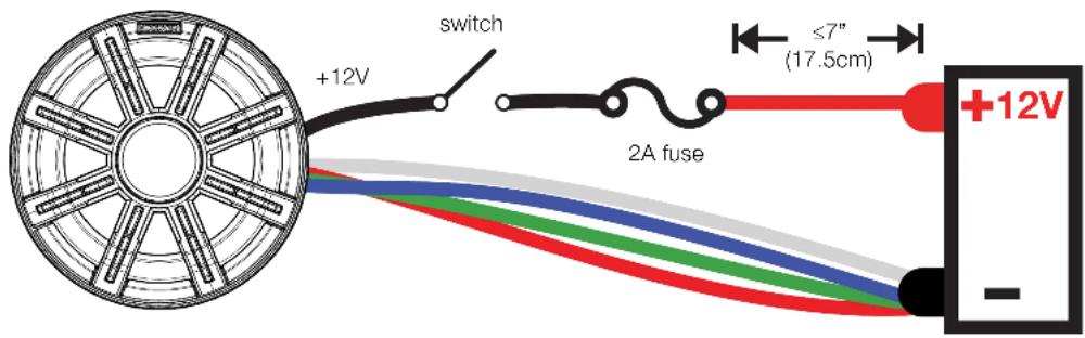
Color Combinations: Splice and combine the ground wires to yield a different color.
Wires Connected to Negative Terminal LED Color
| Red Red | |
| Green Green | |
| Blue Blue | |
| White White | |
| Red/Green Lime Green | |
| Red/Blue Magenta | |
| Blue/Green Aquamarine | |
| Red/Green/Blue | Blue-White |
Speaker Mounting
The sound produced by the MSS speakers is directional. Find the best location for stereophonic sound. If necessary, add more MSS speakers to the system to help distribute and balance the sound-stage.
After determining the best mounting locations, carefully check the areas where the mounting hardware will be placed. If a mounting location does not already exist, cut a hole in the desired location using the templates from the MSS product page at KICKER.com. If necessary, pre-drill the mounting screw holes using a 7/64" (2.5mm) bit following the template.
Use masking tape to help prevent damage to the paint in the locations to be cut or drilled. If you are mounting the speaker to a surface made from thin, soft material such as aluminum, use the provided stainless steel speed nuts to provide threads for the stainless steel mounting screws. If the speaker cut-out locations require you to cut metal, avoid structural metal and braces. If the panel cannot support the weight of the speaker, an optional reinforcing ring may be fastened or adhered to it.
Make sure the mounting screws and speed nuts will not puncture the fuel cell, wiring, or interfere with any mechanical parts on the underside of the mounting surface. If the supplied hardware is not applicable to your installation, some other means of securely attaching the speakers to the boat must be used.

natural_image
Technical line drawing of a mechanical component with multiple screw holes and internal gear-like structure (no text or symbols)Secure speaker to desired location. Possible locations for MSS Speaker Mounting
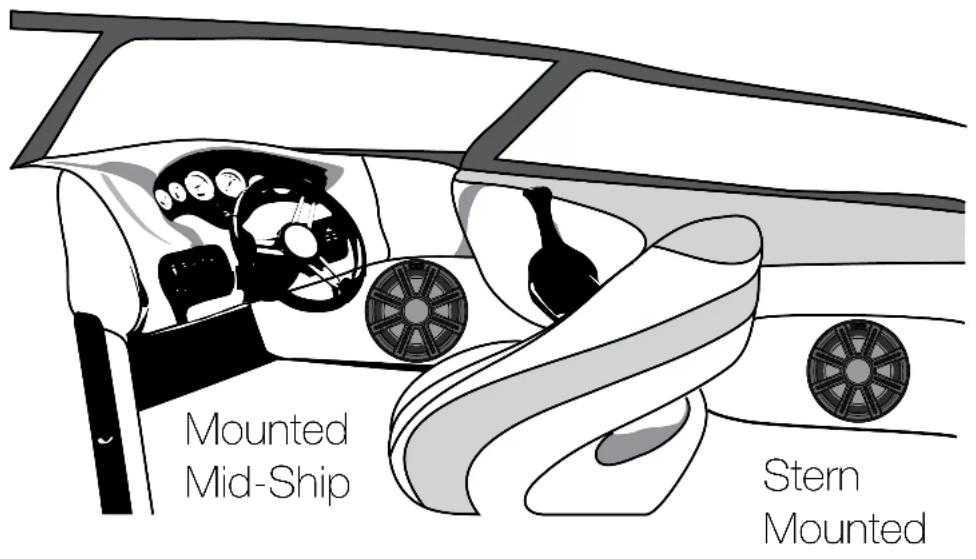
Mounted in the Bow

natural_image
Technical line drawing of a car's front and side views showing steering wheel assembly (no text or symbols)Grille Installation
The MSS Speaker Grille is a snap-lock configuration that must be correctly oriented to be installed properly. To do this, make sure the KICKER badge logo at the top of the grille is in the same orientation as the KICKER "K" logo located on the tweeter bridge, directly above the tweeter.

natural_image
Technical illustration of a mechanical component with two views, one showing internal gear structure and the other showing external gear assembly (no text or symbols)Apply pressure to the inner ring at the 3-o'clock & 9-o'clock positions, indicated by the red arrows. This will engage the snap-lock locations indicated by the red circles.

natural_image
Technical line drawing of a car wheel with radial spokes and central hub, no text or symbols presentTweeter Mounting
The tweeter may be surface-mounted using the Surface Mounting Cup or flush-mounted using the Flush Mounting Cup.
Flush Mounting:
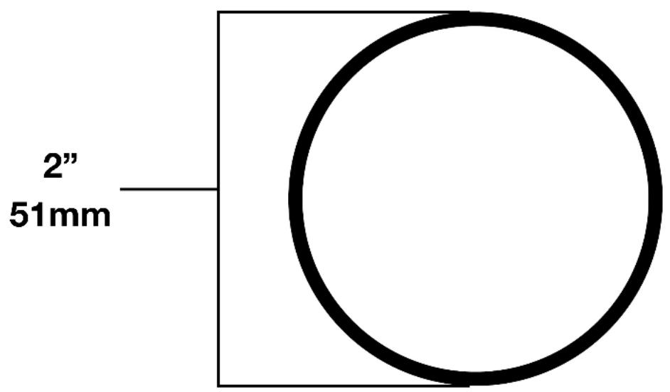
Choose a flat location with space behind the panel to allow room for the motor structure and tweeter. After checking the clearances, cut a 2" (51mm) diameter mounting hole in the panel.
Attach the Retaining Strap to the back of the Flush Mounting Cup - about 5 or 6 complete turns.

natural_image
Technical diagram of a mechanical assembly with a pulley and spring, showing directional arrows indicating motion (no text or symbols)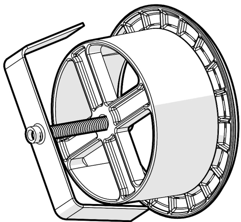
natural_image
Technical line drawing of a mechanical component with internal gears and housing (no text or symbols)Push the Flush Mounting Cup into the mounting hole until the Retaining Strap is through and “catches” the inside of the mounting surface.

natural_image
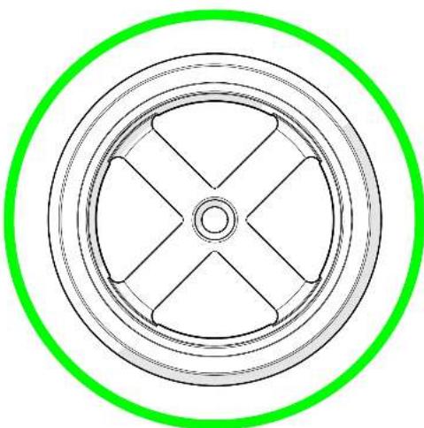
Technical line drawing of a mechanical component with a circular inset showing an arrow pointing to a component (no text or symbols present)Position the Flush Mounting Cup so the rear crossing is oriented as an "x" not a "+". This will prevent the wires from becoming pinched.
natural_image
Circular diagram with concentric rings and radial segments, no text or symbols present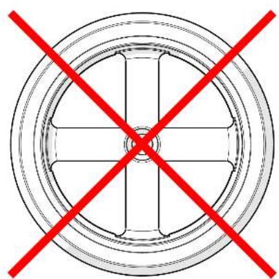
natural_image
Circular diagram with a central crosshair and red X-shaped prohibition symbol (no text or labels)Hold the Retaining Strap and Flush Mounting Cup in place while using a screwdriver to finish securing the cup to the mounting location.

natural_image
Technical line drawing of a mechanical component with no visible text or symbolsRoute the wires through the Flush Mounting Cup.
natural_image
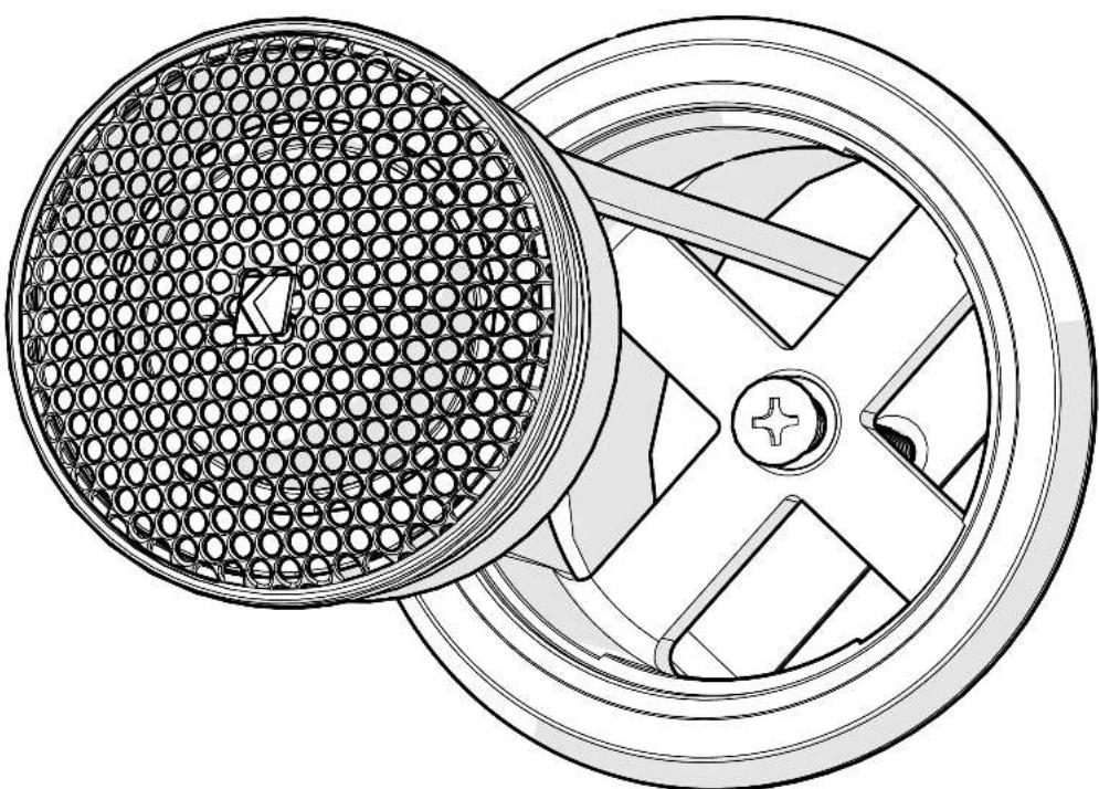
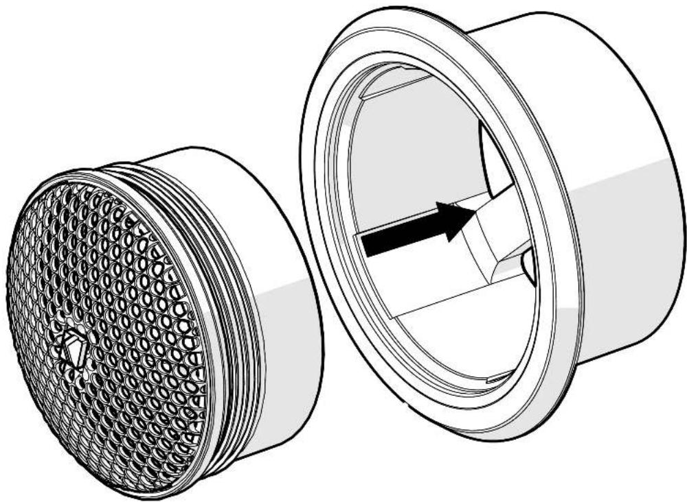
Technical line drawing of a wheel and disc assembly (no text or symbols)With the tweeter positioned so the "K" badge is orientated up, gently push the tweeter into the Flush Mounting Cup until it fully seats.
natural_image
Technical line drawing of two mechanical components with a meshed inner shell and a circular housing, showing internal structure (no text or symbols)To remove the tweeter, push on the back of the tweeter until it pops out.

natural_image
Technical line drawing of a mechanical component with a central shaft and internal structure (no text or symbols)Surface Mounting:
Position the Surface Mounting Cup on the desired surface and mark the mounting holes.
Drill two 7/64" holes for the mounting screws and one 1/4" hole through which to route the tweeter wire.
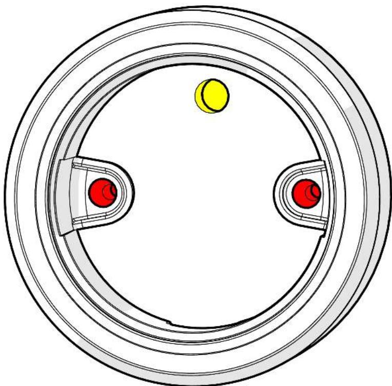
natural_image
Circular diagram with concentric rings and three red and yellow circular elements, no text or symbols present.Position the Surface Mounting Cup so that the weep hole is oriented down.
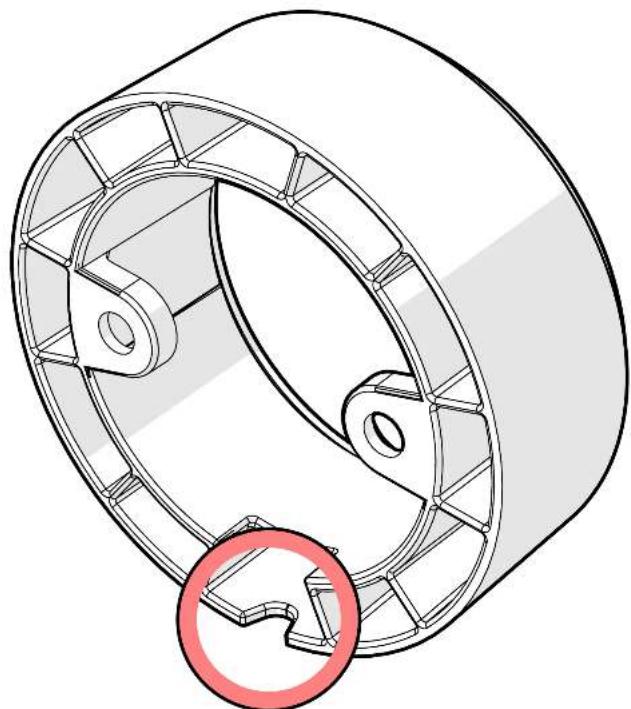
natural_image
Technical line drawing of a mechanical component with internal gear-like structure and a red circular annotation (no text or symbols)Secure the Surface Mounting Cup to the surface using the provided screws.

natural_image
Technical line drawing of a circular mechanical component with two rotating arms and a central hub (no text or symbols)Route the tweeter wire through the hole in the mounting surface.

natural_image
Technical line drawing of a mechanical component with a meshed circular base and coiled pulley (no text or symbols)With the tweeter positioned so the "K" badge is orientated up, gently push the tweeter into the Surface Mounting Cup until it fully seats.
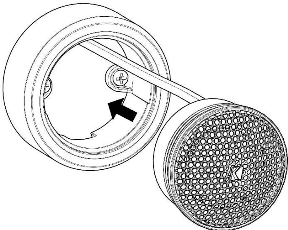
natural_image
Technical line drawing of a mechanical pulley system with a meshed outer ring and a central shaft (no text or symbols)To remove the tweeter, insert a 90-degree pick into the weep hole to work the tweeter out of the Surface Mounting Cup.
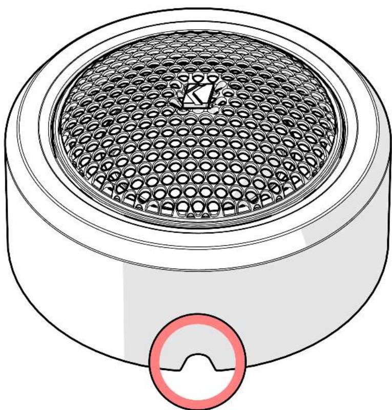
natural_image
Technical line drawing of a cylindrical mechanical component with a meshed inner structure and a red circular symbol below (no text or labels)When purchased from an Authorized KICKER Dealer, KICKER warrants this product to be free from defects in material and workmanship under normal use for a period of TWO (2) YEARS from date of original purchase with receipt. If this product is identified as "Refurbished" or "B Goods", the warranty is limited to a period of THREE (3) MONTHS from the date of original purchase. In all cases you must have the original receipt. Should service be necessary under this warranty for any reason due to manufacturing defect or malfunction during the warranty period, KICKER will repair or replace (at its discretion) the defective merchandise with equivalent merchandise. Warranty replacements may have cosmetic scratches and blemishes. Discontinued products may be replaced with more current equivalent products. This warranty is valid only for the original purchaser and is not extended to owners of the product subsequent to the original purchaser. Any applicable implied warranties are limited in duration to a period of the express warranty as provided herein beginning with the date of the original purchase at retail, and no warranties, whether express or implied, shall apply to this product thereafter. Some states do not allow limitations on implied warranties; therefore, these exclusions may not apply to you. This warranty gives you specific legal rights; however you may have other rights that vary from state to state.
WHAT TO DO IF YOU NEED WARRANTY OR SERVICE:
Defective merchandise should be returned to your local Authorized Stillwater Designs (KICKER) Dealer for warranty service. Assistance in locating an Authorized Dealer can be found at www.KICKER.com or by contacting Stillwater Designs directly. You can confirm that a dealer is authorized by asking to see a current authorized dealer window decal.
If it becomes necessary for you to return defective merchandise directly to Stillwater Designs (KICKER), call the KICKER Customer Service Department at (405) 624-8510 for a Return Merchandise Authorization (RMA) number. Package only the defective items in a package that will prevent shipping damage, and return to:
Stillwater Designs
3100 North Husband St
Stillwater, OK 74075
The RMA number must be clearly marked on the outside of the package. Please return only defective components. The return of functioning items increases your return freight charges. Non-defective items will be returned freight collect to you. For example, if a subwoofer is defective, only return the defective subwoofer, not the entire enclosure. Include a copy of the original receipt with the purchase date clearly visible, and a “proof-of-purchase” statement listing the Customer’s name, Dealer’s name and invoice number, and product purchased. Warranty expiration on items without proof-of-purchase will be determined from the type of sale and manufacturing date code. Freight must be prepaid; items sent freight-collect, or COD, will be refused.
WHAT IS NOT COVERED?
This warranty is valid only if the product is used for the purpose for which it was designed. It does not cover:
o Damage due to improper installation
o Subsequent damage to other components
o Damage caused by exposure to moisture, excessive heat, chemical cleaners, and/or UV radiation
o Damage through negligence, misuse, accident or abuse. Repeated returns for the same damage may be considered abuse
o Any cost or expense related to the removal or reinstallation of product
o Speakers damaged due to amplifier clipping or distortion
o Items previously repaired or modified by any unauthorized repair facility
o Return shipping on non-defective items
o Products with tampered or missing barcode labels
o Products with tampered or missing serial numbers
o Products returned without a Return Merchandise Authorization (RMA) number
o Products purchased from an UNAUTHORIZED dealer
o Freight Damage
o The cost of shipping product to KICKER
o Service performed by anyone other than KICKER
HOW LONG WILL IT TAKE?
KICKER strives to maintain a goal of one-week service for all acoustics (subwoofers, midrange drivers, tweeters, crossovers, etc) returns. Delays may be incurred if lack of replacement inventory or parts is encountered. Failure to follow these steps may void your warranty. Any questions can be directed to the KICKER Customer Service Department at (405) 624-8510. Contact your International KICKER dealer or distributor concerning specific procedures for your country's warranty policies.
Contact your International KICKER dealer or distributor concerning specific procedures for your country's warranty policies.
Our goods come with guarantees that cannot be excluded under the Australian Consumer Law. You are entitled to a replacement or refund for a major failure and for compensation for any other reasonably foreseeable loss or damage. You are also entitled to have the goods repaired or replaced if the goods fail to be of acceptable quality and the failure does not amount to a major failure.


- IMPORTANT SAFETY WARNING
- Specifications
- Wiring Configuration
- LED Wiring Configuration
- Speaker Mounting
- Secure speaker to desired location. Possible locations for MSS Speaker Mounting
- Grille Installation
- Tweeter Mounting
- Flush Mounting:
- Surface Mounting:
- WHAT TO DO IF YOU NEED WARRANTY OR SERVICE:
- WHAT IS NOT COVERED?
- HOW LONG WILL IT TAKE?
Brand : KICKER
Model : Premium 51MSS8
Category : Loudspeaker