
DS-LEDUNV1200 - Wall mount Peerless-AV - Free user manual and instructions
Find the device manual for free DS-LEDUNV1200 Peerless-AV in PDF.


| Product Type | Wall Mount for LED/LCD displays |
| Compatible Screen Size | Up to 1200mm (approximately 47 inches) |
| VESA Compatibility | Standard VESA patterns up to 600x400mm |
| Maximum Load Capacity | 120 kg (265 lbs) |
| Tilt Range | -5° to +15° |
| Swivel Range | ±30° |
| Profile Depth | Adjustable from 50mm to 500mm |
| Material | Steel with powder coating |
| Mounting Type | Single stud or concrete wall |
| Color | Black |
| Dimensions (W x H x D) | 650 x 400 x 50 mm (closed) |
| Net Weight | 5.5 kg (12 lbs) |
| Power Source | None (passive mount) |
| Key Features | Universal design, tilt, swivel, extension, cable management |
| Maintenance | Periodic check of bolts and screws; clean with dry cloth |
| Safety | Use with rated weight; attach to solid wall; avoid over-torquing |
| Spare Parts & Repairability | Replacement hardware available; repair via authorized centers |
| General Information | Professional-grade mount for commercial and residential use |
Frequently Asked Questions - DS-LEDUNV1200 Peerless-AV
User questions about DS-LEDUNV1200 Peerless-AV
0 question about this device. Answer the ones you know or ask your own.
Ask a new question about this device
Download the instructions for your Wall mount in PDF format for free! Find your manual DS-LEDUNV1200 - Peerless-AV and take your electronic device back in hand. On this page are published all the documents necessary for the use of your device. DS-LEDUNV1200 by Peerless-AV.
USER MANUAL DS-LEDUNV1200 Peerless-AV
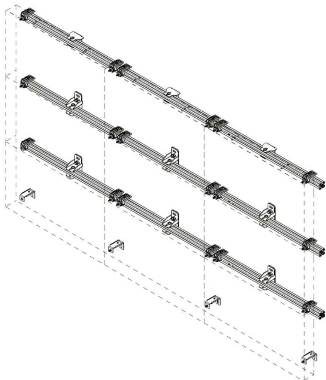
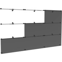
SEAMLESS Kitted Universal Series
*Actual configuration may vary
natural_image
Isometric technical diagram of parallel metal railings with mounting brackets, shown in 3D perspective (no text or symbols)WARNING
This product is designed to be installed on plywood walls. Hardware is included for plywood installation. This product is designed to be installed on flat, unobstructed, vertical walls. Do not install on curved or angled walls. Before installing make sure the supporting surface will support the combined load of the equipment and hardware. Screws must be tightly secured. Do not overtighten screws or damage can occur and product may fail. Never exceed the Maximum Load Capacity. Always use an assistant or mechanical lifting equipment to safely lift and position equipment. This product is intended for indoor use only. Use of this product outdoors could lead to product failure or personal injury. Be careful not to pinch fingers when operating the mount. For support please call customer care at 1-800-865-2112.
Symbols

Do not overtighten screws.

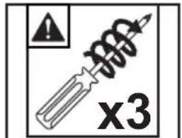
Screws must get at least three full turns and fit snug.


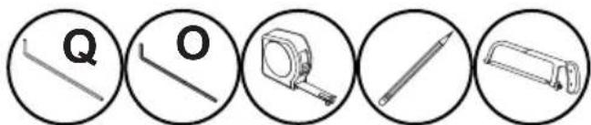
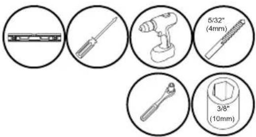
Tools Needed for Assembly.


Parts (Before beginning, make sure you have all parts shown below). *Refer to parts list included with your model.
Parts List
Description
Qty.*
A latch assembly
B 4' horizontal extrusion
C wall plate
D depth adjustment bracket
E connector plate
F 1/4" SAE washer
G #14 x 1.75" wood screw
H M5 cup washer
I M5 flat head screw
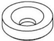
J M6/M8 cup washer
K M6 flat head screw
L M8 flat head screw
M M10 socket cap screw
A
latch assembly

natural_image
Technical line drawing of a mechanical assembly with no visible text or symbolsB
4' horizontal extrusion
A

natural_image
Technical line drawing of a mechanical assembly with no visible text or symbolsD
depth adjustment bracket

C
wall plate

F
1/4" SAE washer

G
14 x 1.75" wood screw

H
M5 cup washer
J
M6/M8 cup washer

|
M5 flat
head screw

K
M6 flat
head screw

L
M8 flat
head screw

natural_image
Simple line drawing of a screw with no text or symbolsM
M10 socket
cap screw

natural_image
Technical line drawing of a threaded screw or bolt (no text or symbols)Parts List
Description Qty.
N spacer 2
O 3mm allen wrench 1
P wall plate shim 10
Q 4mm allen wrench 1
R spacer extension 2
S M5 flat head screw 8
T 1/4" flat washer 8
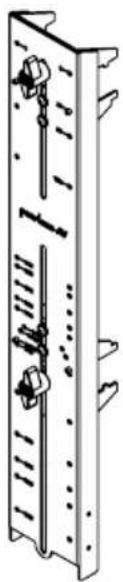
N
spacer
natural_image
Technical line drawing of a mechanical assembly with mounting holes and internal components (no text or symbols)R
spacer extension

0
3mm allen wrench

Q
4mm allen wrench
P
wall plate
shim

S
M5 flat head screw

T
1/4" flat washer

natural_image
Simple line drawing of a circular washer or washer (no text or symbols)DS-LEDUNVSPACER Kit:
Included with preconfigured models and also sold separately.
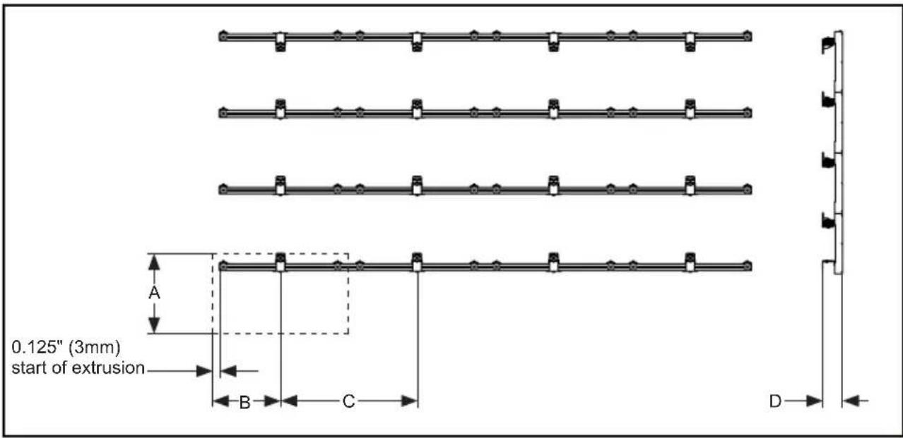
| Compatible Display | Bottom of the video wall to the top of the first wall plate. Dimension A | Side of video wall to center of first wall plate Dimension B | Center to center wall plates. Dimension C | System Depth Range. Dimension D |
| Absen Acclaim Plus/Pro/V3 | 345.24 | 305 | 610 | 120.65-137.67 |
| Absen KL II | 395.74 | 320 | 640 | 136.40-153.67 |
| Absen NX | 582.74 | 240 | 480 | 115.06-132.08 |
| AOTO CVE | 360.25 | 300 | 600 | 108.71-125.98 |
| Barco XT | 382.17 | 305 | 610 | 142.75-159.76 |
| Christie CSII | 368.24 | 300 | 600 | 108.71-125.98 |
| Christie CSIII | 368.24 | 300 | 600 | 100.58-117.86 |
| Fabulux T Series | 515.24 | 250 | 500 | 103.88-121.16 |
| INFiLED WP | 365.49 | 300 | 600 | 101.34-118.36 |
| INFiLED WT | 365.49 | 300 | 600 | 101.34-118.36 |
| Jupiter ZavusXP0.7 | 290.73 | 240 | 480 | 99.57-116.58 |
| Jupiter ZavusXP0.9-1.2 | 348.23 | 300 | 600 | 99.57-116.58 |
| Just Video Walls | 361.9 | 300 | 600 | 110.74-127.76 |
| Leyard GF | 504.74 | 320 | 640 | 145.54-162.56 |
| LG LSAC | 700.68 | 300 | 600 | 122.68-139.70 |
| LG LSBB | 384.45 | 300 | 600 | 127.25-144.27 |
| LG LSBE | 380.37 | 300 | 600 | 143.51-160.53 |
| LG LSBF | 715.72 | 300 | 600 | 143.51-160.53 |
| LG LSCA-GK2 (500x500) | 532.79 | 250 | 500 | 136.65-153.67 |
| LG LSCA-GK (500x1000) | 1032.79 | 250 | 500 | 136.65-153.67 |
| LG LSCB | 365.49 | 300 | 600 | 101.09-118.11 |
| Linsn MA640 | 505.74 | 320 | 640 | 128.52-145.79 |
| Linsn N169S | 382.74 | 300 | 600 | 117.60-134.87 |
| MAXHUB M27 | 378.87 | 320 | 640 | 102.61-119.63 |
| Philips 27BDL6000 | 382.74 | 304 | 608 | 130.55-147.57 |
| Philips 28HDL5000 | 538.69 | 250 | 500 | 113.54-130.81 |
| Philips 44HDL5000 | 1038.69 | 250 | 500 | 113.54-130.81 |
| Planar 27" DLP | 380.94 | 302.4 | 604.8 | 116.58-133.86 |
| Planar 36" DLP | 721.14 | 302.4 | 604.8 | 116.58-133.86 |
| QST PH | 365.49 | 300 | 600 | 108.20-125.47 |
| Samsung IEC | 373.24 | 300 | 600 | 109.73-127 |
| Sharp NEC E Series | 379.49 | 300 | 600 | 100.58-117.60 |
| Sharp NEC FA, FC, FE | 378.74 | 304 | 608 | 120.65-137.67 |
| SNA VST | 480.74 | 200 | 400 | 117.60-134.62 |
| SNA VTII | 475.74 | 200 | 400 | 144.78-162.05 |
| Sony BC | 377.74 | 304 | 608 | 120.14-137.16 |
| Sony BHCH | 345.24 | 305 | 610 | 140.21-157.22 |
| Unilumin ULWIII | 378.24 | 300 | 600 | 116.33-133.35 |
| Unilumin Umini III | 378.24 | 300 | 600 | 112.01-129.28 |
| Unilumin Upanel II | 383.82 | 305 | 610 | 139.70-156.72 |
| Unilumin UPanelS | 381.53 | 305 | 610 | 142.75-159.77 |
| Unilumin UPanelSII | 383.82 | 305 | 610 | 136.65-153.92 |
| Unilumin Uslim II (500x250) | 290.69 | 250 | 500 | 110.23-127.51 |
| Unilumin Uslim II (500x500) | 499.9 | 250 | 500 | 110.23-127.51 |
| Unilumin Uslim II (500x1000) | 1040.74 | 250 | 500 | 110.23-127.51 |
| Unilumin UTWIII | 580.79 | 240 | 480 | 99.82-116.84 |
2
Optional: connecting two horizontal extrusions.

2-1
Determine the required extrusion length with the following extrusion cut to length formula:
Video Wall Width - 0.25" (6mm) = Extrusion Length

2-2
Now that the extrusions are cut to length, separate the extrusions and slide wall plates onto horizontal extrusions and tighten with the wall plate fully extended (one wall plate per display unless the display is >960mm wide, in which case there will be two wall plates per display).

WARNING
When installing Peerless wall mounts on a wood stud wall covered with plywood, verify that the wood studs are a minimum of 2" x 4" nominal size and plywood is a minimum Grade BC, 1/2" (13mm) thick. Plywood may be covered by gypsum board (drywall) up to 5/8" thick.
2-3
Install the bottom row, first extrusion assembly, on the laser line per table (step 1), dimension "A". Install additional bottom row extrusions one at a time using connector plates to join extrusions. Drill mounting holes and install screws and washers with top edge of the wall plates on the laser line.


3
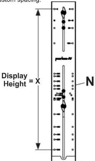
Determine the height of the display being mounted and locate the same dimension on the front of the spacer. If the display height is above 540mm, add the spacer extension. If display height is not listed on the spacer, measure the display to set custom spacing.
X ≤ 540mmX >


X = Not listed

3-1
Add the extension for displays taller than 540mm. Move the spacer bracket and clamp to the lower extension.

4a
Move spacer bracket and clamp to the desired display height. This may require adjusting the pins of spacer bracket.


4a-1
Optional: Remove and replace pins to align with correct display height.

4b
If the display height is not listed on the spacer, measure the display to set the spacing.

natural_image
Three circular icons showing different mechanical or electrical components: a wrench, a screwdriver, and a measuring tool (no text or symbols)
flowchart
graph TD
    A["Remove"] --> B["Adjust to 0mm"]
    B --> C["Return to 30mm and reattach the clamp that was removed."]
    C --> D["Adjust and secure"]
    D --> E["Add to 10mm"]
    E --> F["Remove pins"]
    F --> G["Display Height"]
    G --> H["Avoid damage to module(s). Remove if possible."]
5
Install remaining extrusions using the spacers. Clamp the upper spacer jaw assembly to an uninstalled extrusion assembly. Clamp the bottom spacer jaw assembly to the installed extrusion. Vertically align extrusions with a laser. Drill mounting holes into supporting surface and install wall plates to the wall.

natural_image
Four circular icons with abstract line and symbol patterns: a printer, a ruler, and a diagonal line (no text or labels)


6
Loosen clamps and remove spacers. Repeat steps above to install the next extrusion.
Engage and secure connector plate to mounted extrusions. Secure wall plates to wall. Remove spacer when extrusions are fully secured.

7
Set a laser level so that it is parallel to the mounting surface (wall). Measure to the face of the extrusion so that all points of the extrusion are the same distance from the laser line, creating one flat plane across the face of the mount. Tighten screws.

Double check using a straight edge to span three extrusions. Adjust low and high spots as needed.


9
Hook display cabinets onto horizontal extrusion, adjust height to level and join cabinets together using connecting system. Adjust plumb, close latch, then run cables one at a time starting from left to right.
HEIGHT ADJUSTMENT

9-1
Hook display cabinets onto horizontal extrusion, adjust height to level and join cabinets together using connecting system. Close latch, then run cables one at a time starting from left to right.
9-2
To remove, start from the top right. Open latch assemblies, disconnect cables, separate cabinets and remove displays one at a time.


Optional: Height adjustment screw can be removed from top row displays.
www.peerless-av.com/warranty • www.peerless-av.com • www.peerless-av.com/patents
peerless-AV®
Peerless-AV
2300 White Oak Circle
Aurora, IL 60502, USA
info@peerless-av.com
(800) 865-2112
(630) 375-5100
Peerless-AV EMEA
Unit 2. Curo Park
Frogmore, St. Albans,
Hertfordshire, AL2 2DD
United Kingdom
+44 (0) 1923 200 100
Peerless-AV B.V.
Papendorpseweg 75
3528 BJ Ütrecht
The Netherlands
+31 (0) 70 770 8037
Peerless-AV Latin America
Brand : Peerless-AV
Model : DS-LEDUNV1200
Category : Wall mount