
RVCFD-79F - Vacuum Cleaner CRUX - Free user manual and instructions
Find the device manual for free RVCFD-79F CRUX in PDF.


| Product Type | Vacuum Cleaner |
| Brand | CRUX |
| Model | RVCFD-79F |
| Dimensions (L x W x H) | 12.5 x 9.8 x 14.2 inches |
| Weight | 8.5 lbs |
| Power Source | 120V AC, 60Hz |
| Power Consumption | 1200W |
| Suction Power | 300 Air Watts |
| Dust Capacity | 2.5 liters |
| Cord Length | 20 feet |
| Noise Level | 75 dB |
| Filtration System | HEPA washable filter |
| Attachments Included | Crevice tool, dusting brush, floor nozzle |
| Bagless | Yes |
| Body Material | ABS plastic |
| Color | Black / Red |
| Warranty | 1 year limited |
| Safety Features | Overheating protection, indicator light |
| Maintenance Required | Empty and wash filter monthly |
| Spare Parts Availability | Filters, belts, hoses available online |
| Certifications | ETL, RoHS |
Frequently Asked Questions - RVCFD-79F CRUX
User questions about RVCFD-79F CRUX
0 question about this device. Answer the ones you know or ask your own.
Ask a new question about this device
Download the instructions for your Vacuum Cleaner in PDF format for free! Find your manual RVCFD-79F - CRUX and take your electronic device back in hand. On this page are published all the documents necessary for the use of your device. RVCFD-79F by CRUX.
USER MANUAL RVCFD-79F CRUX
- Activates Rear-view camera function via OBD II port.
- Forced rear view camera option.
- Retains functionality of Factory-installed Navigation System for passenger access at anytime.
- Plug and Play Installation.
RADIO COMPATIBILITY:
- MyFord Touch 8" MS-Sync Gen 3
IMPORTANT INSTALLATION NOTES:
- OBD2 dongle can be used for one vehicle.
- During programming process, maintain battery voltage above 12V.
- Do not interrupt while programming radio by disconnecting OBD2-Dongle or Turn key OFF.
- Programming process takes less than 15 seconds.
- Vehicles with Manual Transmission are not compatible.
PARTS INCLUDED:
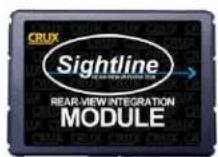
RVCFD-79F
VIM MODULE

RVCFD-79F VIDEO INTERFACE MODULE
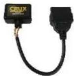
RVCFD-79F
OBD2 CODER
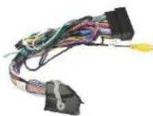
RVCFD-79F
T-HARNESS
LED INDICATOR STATUS:
OBD2 CODER:
The LEDs are located inside the right side of the 8-Pin connector of the OBD2 Coder.
LED
BLUE
Solid
RED
Solid
Blinking with blue LED OFF
GREEN
Solid
Blinking with blue LED OFF
RED & GREEN
Solid
Description
Normal Operation
Invalid Operation
License Expired (OBD2 Coder has been used)
RVC Coding successful
License Invalid / Blue LED ON = Diagnostic coding in progress
Can Communication Error or Diagnostic session terminated with error

natural_image
Close-up of a black electrical connector with a coiled cable and labeled LED (no text or symbols beyond label)rev.082117
RVCFD-79F Video Interface Module:
The LEDs are located inside the left side of the 14-Pin connector of the Video Interface Module.
BLUE ON Valid CAN / Normal operation mode
BLUE OFF Sleep Mode
RED ON RVC Programmed Successfully
RED OFF RVC Coding has been completely removed

LEDs
OBD2 CODER LICENSE NOTE:
The OBD2 Coder can only be licensed to one vehicle. To verify if the OBD2 Coder has been used or not, connect power to the OBD2 connector as follows: Pin 4 or 5 to Ground and Pin 16 to +12V and observe the LED condition:
RED flashing = License has been used
GREEN flashing= Valid License (not yet used)

OBD2 CODING PROCESS:
- Locate the OBD2 port, typically under the steering wheel column.
- Turn the key to the ON position (do not start the engine). Turn off head lights.
- Turn on radio and wait until it is in its normal operation.
- Plug the OBD2 Coder into the OBD2 port.
- Wait until you see a solid GREEN LED then remove the OBD2 coder from the OBD2 port.
- Turn the key to the OFF position, remove key, open driver door then close it.
- Open the driver door, start engine and put the gear in REVERSE. If a camera is connected, you will see the camera image on the radio screen. If no camera is connected, within 20 seconds of putting the gear in reverse, the radio screen will switch to a blue screen with the message "Service Rear Vision System. This means that the RVC was coded successfully.
- There is an option to the remove the RVC coding. To do this, repeat steps 2 to 5 and put the gear in reverse to verify that the coding has been removed.
INSTALLATION INSTRUCTIONS:
- Remove the display monitor and connect the RVCFD-79F 54-Pin T-harness between the factory display and harness.
- Connect the WHITE wire on the RVCFD-79F harness labeled "Reverse Output 12V 500mA" to the camera +12V power (RED wire) and the BLACK wire labeled "Camera Ground" to the camera ground wire.
- Connect the YELLOW female RCA labeled "VDO Signal Output" to the camera cable RCA.
-
Apply the e-brake and put the vehicle in reverse gear. Verify the camera image on the display.
-
To enable the Forced RVC feature, set DIP#4 to ON and apply +12V to the GREEN wire of the RVCFD-79F T-harness. We recommend adding a toggle switch (not included).
-
To enable the Video in Motion function, set DIP#1 to ON. Set to OFF to disable this function.
NOTES:
- After disconnecting the factory 54-pin radio harness, it may take up to 2 minutes for the radio to perform self diagnostic and reboot.
- After the reverse gear is disengaged, the WHITE wire will be energized for 11 seconds meaning the reverse camera will stay on for 11 seconds.
- The WHITE wire will generate +12V while in Forced RVC feature.
DIP SWITCH SETTINGS:
The DIP switches are on the RVCFD-79F VIM Module.
| DIP 1 | OFF = VIM Disabled / ON = VIM Enabled | |
| DIP 2 | ON | Rear-View Camera Enable |
| DIP 3 | OFF | N/A |
| DIP 4 | ON = Forced RVC Option (connect GREEN wire to +12V) | |
| DIP 5 | OFF | CAN Termination Radio Side |
| DIP 6 | ON | CAN Termination Car Side |
VEHICLE APPLICATIONS:
FORD
2015-2017 C-MAX
COMPATIBLE RADIO:
- MyFord Touch 8" MS-Sync Gen 3

natural_image
Interior view of a car dashboard with digital display and SONY branding (no readable text or symbols)Brand : CRUX
Model : RVCFD-79F
Category : Vacuum Cleaner