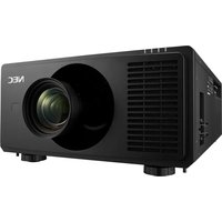
PX2201UL - Video projector SHARP - Free user manual and instructions
Find the device manual for free PX2201UL SHARP in PDF.


| Product Type | Video Projector |
| Brand | Sharp |
| Model | PX2201UL |
| Display Technology | DLP |
| Native Resolution | WXGA (1280 x 800) |
| Brightness (Lumens) | 3200 ANSI Lumens |
| Contrast Ratio | 20000:1 |
| Lamp Type | Ultra High Efficiency Lamp |
| Lamp Life (Normal/Eco) | 5000 / 10000 hours |
| Projection Lens | 1.2x Manual Zoom / Focus |
| Keystone Correction | Vertical ±40° |
| Input Ports | HDMI, VGA, Composite, Audio |
| Output Ports | Audio Out, RS-232C |
| Weight | 2.6 kg (5.7 lbs) |
| Dimensions (W x D x H) | 315 x 230 x 100 mm |
| Power Consumption | 260W (Normal) / 0.5W (Standby) |
| Noise Level | 35 dB (Normal) / 28 dB (Eco) |
| Speaker | Built-in 10W Mono |
| Air Filter Type | Replaceable dust filter |
| Cleaning | Clean filter every 500 hours with vacuum cleaner |
| Safety Features | Kensington lock slot, auto power off |
| Spare Parts | Replacement lamp (Sharp OEM), air filter |
| Repairability | Modular design; lamp and filter user-replaceable |
Frequently Asked Questions - PX2201UL SHARP
User questions about PX2201UL SHARP
0 question about this device. Answer the ones you know or ask your own.
Ask a new question about this device
Download the instructions for your Video projector in PDF format for free! Find your manual PX2201UL - SHARP and take your electronic device back in hand. On this page are published all the documents necessary for the use of your device. PX2201UL by SHARP.
USER MANUAL PX2201UL SHARP
Please visit our web site for User's Manual in the latest version.
https://www.sharp-nec-displays.com/dl/en/pj_manual/lineup.html
Model No.
NP-PX2201UL
Important Information......v
1. Introduction......1
1-1. Introduction to the Projector....1
1-2. What's in the Box? 4
1-3. Part Names of the Projector....5
1-4. Part Names of the Remote Control....9
Battery Installation 10
Remote Control Precautions....10
2. Projecting an Image (Basic Operation)....12
2-1. Flow of Projecting an Image 12
2-2. Connecting Your Computer/Connecting the Power Cord 13
2-3. Turning on the Projector 15
2-4. Selecting a Source....18
Using the Direct button on the remote control 18
Using the INPUT button on the projector cabinet 19
Select by displaying the On-Screen Menu....19
2-5. Adjusting the Picture Size and Position 20
Adjusting the vertical position of a projected image (Lens shift)....21
Adjusting the focus and zoom of the projected image 23
Adjusting the Tilt Foot 28
2-6. Turning off the Projector 29
3. Convenient Features....30
3-1. Turn off the light of the projector (LENS SHUTTER) 30
3-2. Turning Off the On-Screen Menu (On-Screen Mute)....30
3-3. Shift the On-Screen Menu displaying position....31
3-4. Magnifying a Picture .... 32
3-5. Adjustment of luminance (brightness) and energy-saving effect [LIGHT MODE].....33
3-6. Correcting Horizontal and Vertical Keystone Distortion [KEYSTONE] 34
3-7. Controlling the Projector by Using an HTTP Browser 35
3-8. Storing Changes for Lens Shift [LENS MEMORY] 37
3-9. Adjust boundaries of a projected image [EDGE BLENDING]....38
4. Using On-Screen Menu....44
4-1. Basic operations of the on-screen menu 44
4-1-1. Configuration of the on-screen menu screen ....44
4-1-2. Adjustment bar 45
4-1-3. Confirmation message....45
4-1-4. Changing the number....45
4-2. List of Menu Items....46
4-3. INPUT 49
4-3-1. INPUT SELECTION 49
4-3-2. AUTO SOURCE 49
4-3-3. COLOR SPACE....49
4-3-4. ASPECT RATIO 50
4-3-5. OVERSCAN ....51
4-3-6. IMAGE OPTIONS....51
4-3-7. TEST PATTERN....51
4-3-8. 3D....52
4-3-9. AUTO ADJUST....53
4-4. PICTURE 54
4-4-1. PRESET 54
4-4-2. CONTRAST/BRIGHTNESS/SHARPNESS/COLOR/HUE....54
4-4-3. COLOR TEMPERATURE....54
4-4-4. COLOR GAMUT 54
4-4-5. GAMMA CORRECTION....54
4-4-6. WHITE BALANCE 55
4-4-7. COLOR CORRECTION....55
4-4-8. NOISE REDUCTION....56
4-4-9. DYNAMIC CONTRAST 56
4-4-10. LIGHT OFF TIMER....56
4-5. DISPLAY....57
4-5-1. LENS LOCK 57
4-5-2. LENS CONTROL....57
4-5-3. LENS MEMORY 57
4-5-4. CENTER LENS ....57
4-5-5. DIGITAL ZOOM....58
4-5-6. GEOMETRIC CORRECTION....58
4-5-7. BLANKING 62
4-5-8. EDGE BLENDING....62
4-5-9. SCREEN TYPE 62
4-6. SETUP 63
4-6-1. LANGUAGE....63
4-6-2. ORIENTATION....63
4-6-3. FAN MODE....64
4-6-4. AUTO POWER OFF....64
4-6-5. DIRECT POWER ON 64
4-6-6. NETWORK SETTINGS 65
4-6-7. LIGHT MODE 66
4-6-8. LIGHT ADJUST (LIGHT MODE) 66
4-6-9. CONSTANT BRIGHTNESS (LIGHT MODE)....66
4-6-10. BACKGROUND....66
4-6-11. STARTUP LOGO 67
4-6-12. REMOTE CONTROL....67
4-6-13. TRIGGER-1/2....69
4-6-14. MENU 69
4-7. INFO. And RESET ALL....70
4-7-1. INFO....70
4-7-2. RESET ALL 70
5. Installation and Connections....71
5-1. Connecting to Other Equipment....71
6. Maintenance ....73
6-1. Cleaning the Lens....73
6-2. Cleaning the Cabinet ....73
7. Appendix....74
7-1. Throw distance and screen size ....74
7-2. Compatible Input Signal List....78
7-3. Specifications....80
7-4. Cabinet Dimensions....83
7-5. Pin assignments and signal names of main terminals....84
7-6. Troubleshooting 87
7-7. Feature of each indicator 89
7-8. PC Control Codes and Cable Connection 91
7-9. Troubleshooting Check List 92
Registration Information and Software License
• Apple, Mac, and MacBook are trademarks of Apple Inc. registered in the U.S. and other countries.
- Microsoft and PowerPoint are either a registered trademark or trademark of Microsoft Corporation in the United States and/or other countries.
- NaViSet and ProAssist are trademarks or registered trademarks of Sharp NEC Display Solutions, Ltd. in Japan, in the United States and other countries.
- The terms HDMI and HDMI High-Definition Multimedia Interface, and the HDMI Logo are trademarks or registered trademarks of HDMI Licensing Administrator, Inc. in the United States and other countries.

HIGH-DEFINITION MULTIMEDIA INTERFACE
- DisplayPort™ and the DisplayPort™ logo are trademarks owned by the Video Electronics Standards Association (VESA®) in the United States and other countries.

- HDBaseT™ and the HDBaseT Alliance logo are trademarks of the HDBaseT Alliance.

- DLP® and the DLP logo are trademarks or registered trademarks of Texas Instruments in the United States and other countries.
- PJLink trademark and logo are trademarks applied for registration or are already registered in Japan, the United States of America and other countries and areas.
- Blu-ray is a trademark of Blu-ray Disc Association
- CRESTRON and CRESTRON ROOMVIEW are trademarks or registered trademarks of Crestron Electronics, Inc. in the United States and other countries.
- Ethernet is either a registered trademark or trademark of FUJIFILM Business Innovation Corp.
- Other product and company names mentioned in this user's manual may be the trademarks or registered trademarks of their respective holders.
NOTES
(1) The contents of this user's manual may not be reprinted in part or whole without permission.
(2) The contents of this user's manual are subject to change without notice.
(3) Great care has been taken in the preparation of this user's manual; however, should you notice any questionable points, errors or omissions, please contact us.
(4) Notwithstanding article (3), we will not be responsible for any claims on loss of profit or other matters deemed to result from using the Projector.
(5) This manual is commonly provided to all regions so they may contain descriptions that are pertinent for other countries.
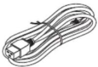
Please use the power cord supplied with this projector. If the supplied power cord does not satisfy requirements of your country's safety standard, and voltage and current for your region, make sure to use the power cord that conforms to and satisfies them.
- The power cord you use must be approved by and comply with the safety standards of your country. Please refer to the page 80 about the power cord specification.
Rated voltage by country is listed below for your reference. For selecting an appropriate power cord, please check rated voltage for your region by yourself.
AC 200-240 V
Safety Cautions
Precautions
Please read this manual carefully before using your NEC projector and keep the manual handy for future reference.
CAUTION

To turn off main power, be sure to remove the plug from power outlet.
The power outlet socket should be installed as near to the equipment as possible, and should be easily accessible.
CAUTION

TO PREVENT SHOCK, DO NOT OPEN THE CABINET.
THERE ARE HIGH-VOLTAGE COMPONENTS INSIDE.
REFER SERVICING TO QUALIFIED SERVICE PERSONNEL.

This symbol warns the user that uninsulated voltage within the unit may be sufficient to cause electrical shock. Therefore, it is dangerous to make any kind of contact with any part inside of the unit.

This symbol alerts the user that important information concerning the operation and maintenance of this unit has been provided.
The information should be read carefully to avoid problems.
WARNING: TO PREVENT FIRE OR SHOCK, DO NOT EXPOSE THIS UNIT TO RAIN OR MOISTURE. DO NOT USE THIS UNIT'S PLUG WITH AN EXTENSION CORD OR IN AN OUTLET UNLESS ALL THE PRONGS CAN BE FULLY INSERTED.
Machine Noise Information Regulation - 3. GPSGV,
The highest sound pressure level is less than 70 dB (A) in accordance with EN ISO 7779.

WARNING
Installing the projector
This projector is an RG3 product. The projector is for professional use and must be installed in location where safety is assured. For this reason, be sure to consult your dealer as installation and attachment/detachment of the lens unit must be performed by a professional service personnel. Never try to install the projector by yourself. This may result in visual impairment etc.
Laser Safety Caution
For USA
This product is classified as Class 3R of IEC 60825-1 Second edition 2007-03.
Complies with FDA performance standards for laser products except for deviations pursuant to Laser Notice No. 50, dated June 24, 2007.

CAUTION – CLASS 3R OF IEC 60825-1 SECOND EDITION LASER PRODUCT
LASER RADIATION – AVOID DIRECT EYE EXPOSURE
For other regions
This product is classified as Class 1 of IEC 60825-1 Third edition 2014-05 and RG3 of IEC/EN 62471-5 First edition 2015-06.
CLASS 1 LASER PRODUCT – IEC 60825-1 THIRD EDITION

CAUTION – RG3 PRODUCT OF IEC/EN 62471-5 FIRST EDITION
No direct exposure to the beam shall be permitted, RG3 IEC/EN 62471-5:2015.
Operators shall control access to the beam within the hazard distance and install the product at the height that will prevent exposures of spectators' eyes within the hazard distance.
Disposing of your used product

In the European Union
EU-wide legislation as implemented in each Member State requires that used electrical and electronic products carrying the mark (left) must be disposed of separately from normal household waste. This includes projectors and their electrical accessories. When you dispose of such products, please follow the guidance of your local authority and/or ask the shop where you purchased the product.
After collecting the used products, they are reused and recycled in a proper way. This effort will help us reduce the wastes as well as the negative impact to the human health and the environment at the minimum level.
The mark on the electrical and electronic products only applies to the current European Union Member States.
Outside the European Union
If you wish to dispose of used electrical and electronic products outside the European union, please contact your local authority and ask for the correct method of disposal.

For EU: The crossed-out wheeled bin implies that used batteries should not be put to the general household waste! There is a separate collection system for used batteries, to allow proper treatment and recycling in accordance with legislation.
According the EU directive 2006/66/EC, the battery can't be disposed improperly. The battery shall be separated to collect by local service.
Important Safeguards
These safety instructions are to ensure the long life of your projector and to prevent fire and shock. Please read them carefully and heed all warnings.
WARNING

- When the projector is damaged, cooling fluids may come out of internal part.
Should this happen, immediately turn off the AC supply to the projector and contact your dealer.
DO NOT touch and drink the cooling fluid. When the cooling fluids are swallowed or contacted with your eyes, please consult medical attention immediately. If you touch the cooling fluid with your hand, rinse your hands well under running water.

Installation
- Please contact your dealer to install the projector.
-
Do not place the projector in the following conditions:
-
on an unstable cart, stand, or table.
- near water, baths, or damp rooms.
- in direct sunlight, near heaters, or heat radiating appliances.
- in a dusty, smoky or steamy environment.
- on a sheet of paper or cloth, rugs or carpets.
- Do not install and store the projector in the below circumstances. Failure to do so may cause of malfunction.
- In powerful magnetic fields
- In corrosive gas environment
- Outdoors
- If you wish to have the projector installed on the ceiling:
- Do not attempt to install the projector yourself.
- The projector must be installed by qualified technicians in order to ensure proper operation and reduce the risk of bodily injury.
- In addition, the ceiling must be strong enough to support the projector and the installation must be in accordance with any local building codes.
WARNING
- Do not cover the lens with the lens cap or equivalent while the projector is on. Doing so can lead to melting of the cap due to the heat emitted from the light output.
- Do not place any objects, which are easily affected by heat, in front of the projector lens. Doing so could lead to the object melting from the heat that is emitted from the light output.
The below pictogram indicated on the cabinet means the precaution for avoiding to place objects in front of the projector lens.

This projector can be installed any angle within vertical and horizontal 360^ range, however, life of optical parts will be shorten in the following installation state:
- When the projector is installed on which lens faces downward.
- When the intake vent on the projector side faces downward in the portrait installation.
For portrait installation, install the projector with the intake vent at the bottom. Observe precautions for portrait installation.
* Consult your dealer regarding the installation.

natural_image
Line drawing of a digital camera mounted on a stand (no text or symbols)
Fire and Shock Precautions

- Ensure that there is sufficient ventilation and that vents are unobstructed to prevent the build-up of heat inside your projector. Allow enough space between your projector and a wall. (→ page xviii)
- Do not try to touch the exhaust vent on the rear side (when seen from the front) as it can become heated while the projector is turned on and immediately after the projector is turned off. Parts of the projector may become temporarily heated if the projector is turned off with the POWER button or if the AC power supply is disconnected during normal projector operation.
Use caution when picking up the projector.
- Prevent foreign objects such as paper clips and bits of paper from falling into your projector. Do not attempt to retrieve any objects that might fall into your projector. Do not insert any metal objects such as a wire or screwdriver into your projector. If something should fall into your projector, disconnect it immediately and have the object removed by a qualified service personnel.
- Do not place any objects on top of the projector.
- Do not touch the power plug during a thunderstorm. Doing so can cause electrical shock or fire.
- The projector is designed to operate on a power supply of 200-240V AC 50/60 Hz. Ensure that your power supply fits this requirement before attempting to use your projector.
- Make sure to mount the power cord stopper before attempting to use your projector. Please refer to page 14 about the power cord stopper.
- Do not look into the light source using optical instruments (such as magnifying glasses and mirrors). Visual impairment could result.
- When turning on the projector, ensure that nobody is facing towards the lens in the path of the light emitted from the laser. Do not look into the lens while the projector is on. Serious damage to your eyes could result. The following graphic symbol indicating that looking into the projector is prohibited is displayed on top of the projector above the lens mounting unit.

- Perform the adjustment from behind or from the side of the projector. Adjusting from the front could expose your eyes to strong light which could injure them.
- Keep any items (magnifying glass etc.) out of the light path of the projector. The light path being projected from the lens is extensive, therefore any kind of abnormal objects that can redirect light coming out of the lens, can cause an unpredictable outcome such as a fire or injury to the eyes.
- Do not place any objects, which are easily affected by heat, in front of a projector exhaust vent.
Doing so could lead to the object melting or getting your hands burned from the heat that is emitted from the exhaust vent. - Handle the power cord carefully. A damaged or frayed power cord can cause electric shock or fire.
- Do not use any power cord other than the one supplied with the projector.
- Do not bend or tug the power cord excessively.
- Do not place the power cord under the projector, or any heavy object.
- Do not cover the power cord with other soft materials such as rugs.
- Do not heat the power cord.
- Do not handle the power plug with wet hands.
- Turn off the projector, unplug the power cord and have the projector serviced by a qualified service personnel under the following conditions:
- When the power cord or plug is damaged or frayed.
- If liquid has been spilled into the projector, or if it has been exposed to rain or water.
- If the projector does not operate normally when you follow the instructions described in this user's manual.
- If the projector has been dropped or the cabinet has been damaged.
- If the projector exhibits a distinct change in performance, indicating a need for service.
- Disconnect the power cord and any other cables before carrying the projector.
- Turn off the projector and unplug the power cord before cleaning the cabinet.
- Turn off the projector and unplug the power cord if the projector is not to be used for an extended period of time.
- When using a LAN cable:
For safety, do not connect to the terminal for peripheral device wiring that might have excessive voltage.
- Do not use the malfunctioned projector. It may cause of not only electric shock or fire but also serious damage to your eye sight or burn injuries.
- Do not let children to operate the projector by themselves. If the projector is operated by children, adults need to attend and keep their eyes on children.
- If damage or malfunction of the projector is found, immediately stop to use it and consult your dealer for repair.
- Never disassemble, repair, and remodel by end users. If these are performed by end users, it may cause of serious problem on users' safety such as visual impairment and burn injuries.
- Consult your dealer for disposing the projector. Never disassemble the projector before disposing it.

CAUTION
- Keep hands away from the lens mounting portion while performing a lens shift. Failure to do so could result in fingers being pinched by the moving lens.
- Do not use the tilt-foot for purposes other than originally intended. Misuses such as gripping the tilt-foot or hanging on the wall can cause damage to the projector.
- Select [HIGH] in Fan mode if you continue to use the projector for consecutive days. (From the menu, select [SETUP] → [FAN MODE] → [HIGH ALTITUDE].)
- Do not unplug the power cord from the wall outlet or projector when the projector is powered on. Doing so can cause damage to the AC IN terminal of the projector and (or) the prong plug of the power cord.
To turn off the AC power supply when the projector is powered on, use the projector's main power switch, a power strip equipped with a switch, or a breaker. - When moving the projector, make sure you have at least four people. Attempting to move the projector alone could result in back pain or other injuries.
- If intense light like laser beams enters from the lens, it could lead to malfunction.
Caution on Handling the Optional Lens
- Contact your dealer to install and replace the lens unit.
- When shipping the projector with the lens, remove the lens before shipping the projector. Always attach the dust cap to the lens whenever it is not mounted on the projector. The lens and the lens shift mechanism may encounter damage caused by improper handling during transportation.
- Do not hold the lens part when carrying the projector. Doing so could cause the focus ring to rotate, resulting in accidental dropping of the projector.
- In the condition the projector is no lens mounted, do not put your hands in the lens mount opening for carrying the projector.
- For mounting, replacing, please contact your dealer. And for cleaning the lens, make sure to power off the projector and disconnect the power cord. Failure to do so can result in eye injury, electric shock, or burn injuries.
- Keep hands away from the lens mounting portion while performing a lens shift. Failure to do so could result in fingers being pinched by the moving lens.
Cable information

CAUTION
Use shielded cables or cables attached ferrite cores so as not to interfere with radio and television reception.
For details, please refer to "5. Installation and Connections" in this user's manual.
Avoid locations with extreme temperatures and humidity
Failure to do so could lead to fire or electric shock or damage to the projector.
The usage environment for this projector is as follows:
- The operating temperature: 0^ to 40^ / 32^ to 104^ / humidity : 20 to 80% (without condensation)
- The storage temperature: -10^ to 60^ / 14^ to 140^ / humidity: 20 to 80% (without condensation)
Precautions when installing or replacing the lens unit sold separately (CENTER LENS)
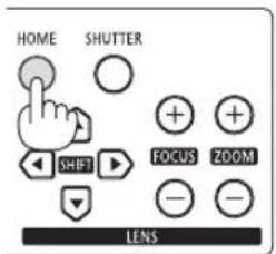
After installation or replacement of the lens, be sure to perform [CENTER LENS] by pressing and holding the HOME button on the projector cabinet for at least two seconds. ( page 16, 57)
By carrying out [CENTER LENS], the adjustment range of the lens shift is calibrated.
Contact your dealer to install and replace the lens unit.
Remote Control Precautions
- Handle the remote control carefully.
- If the remote control gets wet, wipe it dry immediately.
- Avoid excessive heat and humidity.
- Do not short, heat, or take apart batteries.
- Do not throw batteries into fire.
- If you will not be using the remote control for a long time, remove the batteries.
- Ensure that you have the batteries' polarity (+/−) aligned correctly.
- Do not use new and old batteries together, or use different types of batteries together.
- Dispose of used batteries according to your local regulations.
Light Module
- A light module containing multiple laser diodes is equipped in the product as the light source.
- These laser diodes are sealed in the light module. No maintenance or service is required for the performance of the light module.
- End user is not allowed to replace the light module.
-
Contact qualified distributor for light module replacement and further information.
-
Outline of laser emitted from the built-in light module:
- Wave length: 450–460 nm (blue), 635–647 nm (red)
• Maximum power: 680 W
- Radiation pattern from the protective housing:
- Wave length (blue): 450–460 nm
• Maximum laser radiation output: 0.45 mJ - Pulse duration: 0.87 ms
• Repetition frequency: 180 Hz
• Wave length (red): 635–647 nm
• Maximum laser radiation output: 0.77 mJ
- Pulse duration: 1.77 ms
• Repetition frequency: 180 Hz
- The laser module is equipped in this product. Use of controls or adjustments of procedures other than those specified herein may result in hazardous radiation exposure.

CAUTION
- Use of controls or adjustments or performance of procedures other than those specified herein may result in hazardous radiation exposure.
Label Information
These labels are stuck on the below indicated positions.
For USA
The LASER PRODUCT in CLASS 3R conforming to IEC 60825-1 Second edition.
For other regions
The LASER PRODUCT in CLASS 1 conforming to IEC 60825-1 Third edition, and RG3 of IEC/EN 62471-5 First edition 2015.
Label A Label B

natural_image
Pure technical diagram of a mechanical or electrical component with no visible text, numbers, or symbols.Label A: Laser Explanatory Label (Includes LASER APERTURE label)

Label B: Risk Group /Lamp Safety Label


Label C: Manufacturer's ID Label
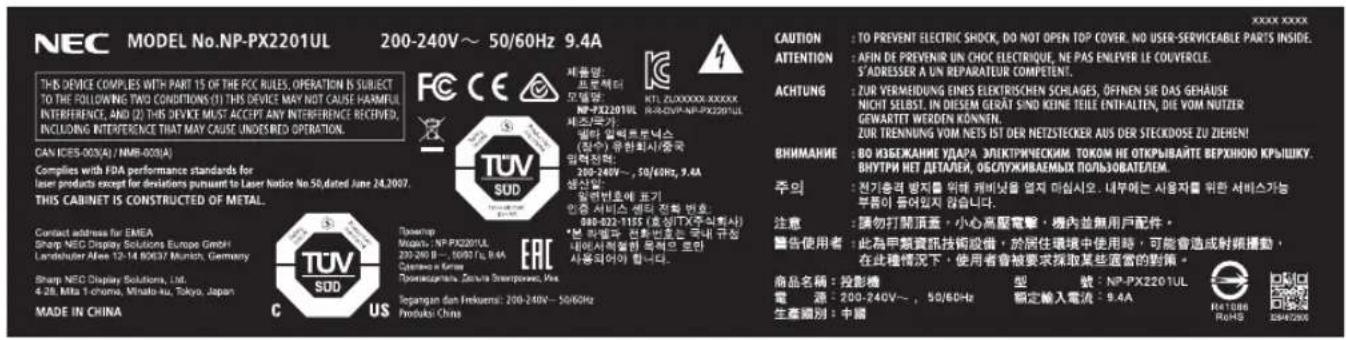
Label D: Barcode label P/N

Laser light radiation range
The figure below shows the maximum radiation range of the laser light. (unit: degree)
Horizontal angle H
| Lens Zoom | ||
| Tele Wide | ||
| NP45ZL 22.0 28.3 | ||
| NP46ZL 17.4 22.1 | ||
| NP47ZL 13.9 18.2 | ||
| NP48ZL 7.0 13.8 | ||
| NP49ZL 4.0 7.0 | ||
Vertical angle V
| Lens Zoom | |
| Tele Wide | |
| NP45ZL 14.1 18.5 | |
| NP46ZL 11.1 14.2 | |
| NP47ZL 8.8 11.6 | |
| NP48ZL 4.4 8.7 | |
| NP49ZL 2.5 4.4 | |

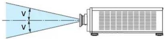
Radiation Zone (HD: Hazard Distance)
- The below table describes the radiation range of emitted light by the projector that is classified as Risk Group 3 (RG3) of IEC/EN 62471-5 First edition 2015.
- Please keep within bounds for installing the projector.
Install a barrier for preventing human eyes from entering the RG3 zone. For the barrier installation position, keep horizontal safety zone over 1 m (2.5 m for USA) from the RG3 zone. In case to install the projector over head, keep over 3 m distance at least between the floor surface and the RG3 zone.
This projector must be installed at a height that will prevent your eyes from being exposed within the RG3 zone.
The equipment administrator (operator) must control the entry of viewers into the RG3 zone.
| Lens | RG3 HD (m) | Screen size (m) | ||
| H | V | |||
| NP45ZL | Wide 1.0 | 1.11 0.69 | ||
| Tele 1.0 0 | 83 0.52 | |||
| NP46ZL | Wide 1.5 | 1.25 0.78 | ||
| Tele 1.8 1 | 15 0.72 | |||
| NP47ZL | Wide 1.8 | 1.20 0.75 | ||
| Tele 2.4 1 | 20 0.75 | |||
| NP48ZL | Wide 2.4 | 1.20 0.75 | ||
| Tele 3.0 0 | 75 0.47 | |||
| NP49ZL | Wide 4.2 | 1.05 0.66 | ||
| Tele 4.8 0 | 69 0.43 | |||
The drawings below are example of typical installation methods. Besides these, when installing the projector at an angle, a security zone is required in the same way.
When installed on a floor or a desktop
![When installed on a floor of a desktop Horizontal security zone: over 1 m (2.5 m for USA) H [Plan view] RG3 zone Horizontal security zone: over 1 m (2.5 m for USA) When installed on a ceiling HD V [Side view] RG3 zone Vertical security zone: over 3 m floor](/content/2026/06/1249348/images/8dc7926c2af45b92846535b7154c10c4b294710a1300b9949ef5ff1bb614a18e.jpg)
* If lens shift is utilized, please consider the shift of projected image according to the volume of lens shift.
When projecting from above to a floor.

Horizontal security zone: over 1 m (2.5 m for USA)

CAUTION
Please heed all precaution for safety.
To install the projector
- This projector is an RG3 product. The projector is for professional use and must be installed in location where safety is assured. For this reason, be sure to consult your dealer as installation and attachment/detachment of the lens unit must be performed by a professional service personnel. Never try to install the projector by yourself. This may result in visual impairment etc.
- The law requires that the lens hood be mounted when using the NP49ZL lens unit in the USA or China. Be sure to ask your dealer to mount the lens hood (model NP01LH).
- For planning the layout of the projector, make sure to take safety measures instructed on the installation manual.
- In order to refuse danger, install either a wall outlet within easy reach for pulling out the power plug in emergency or a device as a breaker to shut down the power supply to the projector.
• Take safety measures preventing human eyes from entering the RG3 zone. - Considering the installation place, select an appropriate lens and secure safety zone that is determined for each lens. For operation on the powered projector as light adjustment, make sure appropriate safety measures have been taken.
- Check the validity of taken security measures if appropriate safety zone based on the installed lens is secured. Periodically check the validity and keep these results.
- Educate the administrator of the projector (operators) about safety before starting to operate the projector.
To use the projector
- Instruct the administrator of the projector (operators) to perform inspections before powering on the projector. (Including the safety check against emitted light by the projector)
- Instruct the administrator of the projector (operators) to be in circumstances able to control the projector whenever the projector is powered on for an emergency.
- Instruct the administrator of the projector (operators) to keep the installation manual, user's manual and inspection records to a place where they can take these documents out easily.
- Instruct them to clarify if the projector is conformed to standards of each country and region.
About Copyright of original projected pictures:
Please note that using this projector for the purpose of commercial gain or the attraction of public attention in a venue such as a coffee shop or hotel and employing compression or expansion of the screen image with the following functions may raise concern about the infringement of copyrights which are protected by copyright law:
[ASPECT RATIO], [KEYSTONE], Magnifying feature and other similar features.

Health precautions to users viewing 3D images
Before viewing, be sure to read health care precautions that may be found in the user's manual included with your 3D eyeglasses or your 3D compatible content such as Blu-ray Discs, video games, computer's video files and the like.
To avoid any adverse symptoms, heed the following:
- Do not use 3D eyeglasses for viewing any material other than 3D images.
- Allow a distance of 2 m/7 feet or greater between the screen and a user. Viewing 3D images from too close a distance can strain your eyes.
- Avoid viewing 3D images for a prolonged period of time. Take a break of 15 minutes or longer after every hour of viewing.
- If you or any member of your family has a history of light-sensitive seizures, consult a doctor before viewing 3D images.
- While viewing 3D images, if you get sick such as nausea, dizziness, queasiness, headache, eyestrain, blurry vision, convulsions, and numbness, stop viewing them. If symptoms still persist, consult a doctor.
• View 3D images from the front of the screen. Viewing from an angle may cause fatigue or eyestrain.
FCC Information (for USA only)
WARNING
- The Federal Communications Commission does not allow any modifications or changes to the unit EXCEPT those specified by Sharp NEC Display Solutions of America, Inc. in this manual. Failure to comply with this government regulation could void your right to operate this equipment.
- This equipment has been tested and found to comply with the limits for a class A digital device, pursuant to Part 15 of the FCC Rules. These limits are designed to provide reasonable protection against harmful interference when the equipment is operated in a commercial environment. This equipment generates, uses, and can radiate radio frequency energy and, if not installed and used in accordance with the instruction manual, may cause harmful interference to radio communications. Operation of this equipment in a residential area is likely to cause harmful interference in which case the user will be required to correct the interference at his own expense.
Supplier's declaration of conformity
This device complies with Part 15 of the FCC Rules. Operation is subject to the following two conditions.
(1) This device may not cause harmful interference, and (2) this device must accept any interference received, including interference that may cause undesired operation.
U.S.Responsible Party: Sharp NEC Display Solutions of America, Inc.
Address: 3250 Lacey Rd, Ste 500
Downers Grove, IL 60515
Telephone Number: 630-467-3000
Type of Product: Projector
Equipment Classification: Class A Peripheral
Model Number: NP-PX2201UL

Other region
WARNING
Operation of this equipment in a residential environment could cause radio interference.

(For Customers in U.K.)
IMPORTANT
- The wires in this mains lead are coloured in accordance with the following code:
GREEN-AND-YELLOW: "Earth"
BLUE: "Neutral"
BROWN: "Live"
- As the colours of the wires in the mains lead of this apparatus may not correspond with the coloured markings identifying the terminals in your plug proceed as follows:
- The wire which is coloured GREEN-AND-YELLOW must be connected to the terminal in the plug which is marked by the letter E or by the safety earth symbol 12 or coloured green or green-and-yellow.
- The wire which is coloured BLUE must be connected to the terminal which is marked with the letter N or coloured black.
- The wire which is coloured BROWN must be connected to the terminal which is marked with the letter L or coloured red.
- Ensure that your equipment is connected correctly. If you are in any doubt consult a qualified electrician.
"WARNING: THIS APPARATUS MUST BE EARTHED."
Clearance for Installing the Projector
Allow ample clearance between the projector and its surroundings as shown below.
The high temperature exhaust coming out of the device may be sucked into the device again.
Avoid installing the projector in a place where air movement from the HVAC is directed at the projector.
Heated air from the HVAC can be taken in by the projector's intake vent. If this happens, the temperature inside the projector will rise too high causing the over-temperature protector to automatically turn off the projectors power.
Example 1 – If there are walls on both sides of the projector.
50 cm/19.7" or greater 50 cm/19.7" or greater

NOTE:
- The drawing shows the proper clearance required for the left and right of the projector assuming sufficient clearance has been kept for the front, back, and top of the projector.
Example 2 – If there is a wall behind the projector.
50 cm/19.7" or greater 50 cm/19.7" or greater

NOTE:
- The drawing shows the proper clearance required for the back of the projector assuming sufficient clearance has been kept for the right, left, and top of the projector.
Example 3 – If there is not much clearance above the projector.
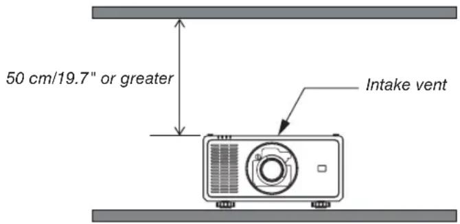
NOTE:
- The drawing shows the proper clearance required for the top of the projector assuming sufficient clearance has been kept for the right, left, front, and back of the projector.
Precautions for Ceiling Installation
Do not install the projector in the following places. Attached substances such as oil, chemicals and moisture may cause deformation or cracks of the cabinet, corrosion of the metal parts, or malfunction.
- Outdoors and places with humid or dust
- Places exposed to oil smoke or steam
- Places where corrosive gases are generated
1. Introduction
1-1. Introduction to the Projector
This section introduces you to your new projector and describes the features and controls.
General
- Single-chip DLP projector with high resolution and high brightness
Realized to project the image in the resolution 1920 × 1200 pixels (WUXGA), the aspect ratio in 16:10, and the brightness in 21,500 lumens. ^*1
*1 Brightness:
| LIGHT MODE Brightness | |
| NORMAL 20,500 lm / 21,500 lm (Center) |
• Superior dust-proof structure
Adapted the cycle cooling system for cooling down the optical parts. By this system, air in the light source is cooled down and circulated. As the result, the optical parts are not exposed to the open air and enable to keep brightness without contamination by dust. ^*2
*2 Can not prevent contamination by dust completely.
Light source · Brightness
- A long-life laser diode is equipped in the light module
The product can be operated at low cost because the laser light source can be used for a long time without requiring replacement or maintenance. The maintenance time may be shortened depending on the operating environment.
- Brightness can be adjusted within a wide range
Unlike with ordinary light sources, the brightness can be adjusted from 30 to 100% in 1% increments.
• [CONSTANT BRIGHTNESS] mode
Brightness normally decreases with use, but by selecting [CONSTANT BRIGHTNESS] mode, sensors inside the projector detect and automatically adjust the output, thereby maintaining constant brightness throughout the life of the light module.
However, if brightness output is set at the maximum, brightness will decrease with use.
Installation
- Wide range of optional lenses selectable according to the place of installation
This projector supports 5 types of optional lenses, providing a selection of lenses adapted to a variety of places of installation and projection methods.
Note that no lens is mounted upon shipment from the factory. Please purchase optional lenses separately and contact your dealer to install and replace the lens unit.
- This projector can be installed any angle within vertical and horizontal 360^ range, however, life of optical parts will be shorten in the following installation state:
- When the projector is installed on which lens faces downward.
- When the intake vent on the projector side faces downward in the portrait installation.
- Power lens control for quick and easy adjustment
By using buttons on the projector or the remote control, zoom, focus, and position (lens shift) can be adjusted.
Videos
- A variety of input terminals such as HDMI, DisplayPort, HDBaseT, SDI, etc.
The projector is equipped with HDMI (1/2), DisplayPort, HDBaseT, SDI, Computer, DVI-D, BNC input terminals.
The projector's HDMI input terminals and DisplayPort input terminals support HDCP.
HDBaseT, promoted and advanced by the HDBaseT Alliance, is a consumer electronic (CE) and commercial connectivity technology.
- Multi-screen projection using multiple projectors
You can line up multiple projectors to display a high resolution image in a larger screen.
Furthermore, the boundaries of the screens are smoothed using an edge blending function.
• Supports HDMI 3D format
This projector can be used to watch videos in 3D using commercially-available 3D emitters that support XPAND 3D and active shutter-type 3D eyewear. The projector is also compatible with 3D images in the DLP® Link format.
Network
• Supports wired LAN
Equips the HDBaseT/LAN (RJ-45) port. Utilizing a wired LAN connected with this port, it enables to control the projector by a computer.
- Convenient utility software (User Supportware)
This projector supports our utility software (NaViSet Administrator 2, ProAssist, etc.).
NaViSet Administrator 2 helps you control the projector by a computer via wired LAN connection.
ProAssist is software for controlling the projector from a computer via a network. Some of the functions in ProAssist may not be compatible with the projector.
Please visit our web site for downloading each software.
URL: https://www.sharp-nec-displays.com/dl/en/index.html
- CRESTRON ROOMVIEW compatibility
The projector supports CRESTRON ROOMVIEW, allowing multiple devices connected in the network to be managed and controlled from a computer.
About this user's manual
The fastest way to get started is to take your time and do everything right the first time. Take a few minutes now to review the user's manual. This may save you time later on. At the beginning of each section of the manual you'll find an overview. If the section doesn't apply, you can skip it.
1-2. What's in the Box?
Make sure your box contains everything listed. If any pieces are missing, contact your dealer. Please save the original box and packing materials if you ever need to ship your projector.
Projector

natural_image
Isometric line drawing of a rectangular electronic device with ventilation grilles and a central lens (no text or symbols)Dust cap for lens (79THE051)
* The projector is shipped without a lens. For the types of lens and throw distances, see page 74.

natural_image
Line drawing of a remote control with keypad and buttons (no text or symbols)Remote control (7N901322)

AAA alkaline batteries (x2)
Power cord × 2

(79TM1021) (79TQ1011)
For Europe/Asia/South America For North America

natural_image
Two overlapping gray rectangular sheets with no text or symbols- Important Infomation (7N8R1201)
- Quick Setup Guide (7N8R1211)

NEC Projector CD-ROM
User's manual (PDF)
(7N953071)
For North America only
Limited warranty
For customers in Europe:
You will find our current valid Guarantee Policy on our Web Site:
https://www.sharpnecdisplays.eu/
1-3. Part Names of the Projector
Front/Top
The lens is sold separately. The description below is for when the NP47ZL lens is mounted.

Rear

Handle (located on 4 positions) For transportation
NOTE:
- For moving the projector, make sure you have at least four people. At the same time, do not grip and hold the projector other than by these handles. Attempting to move the projector with less than four people could result in back pain or other injuries.
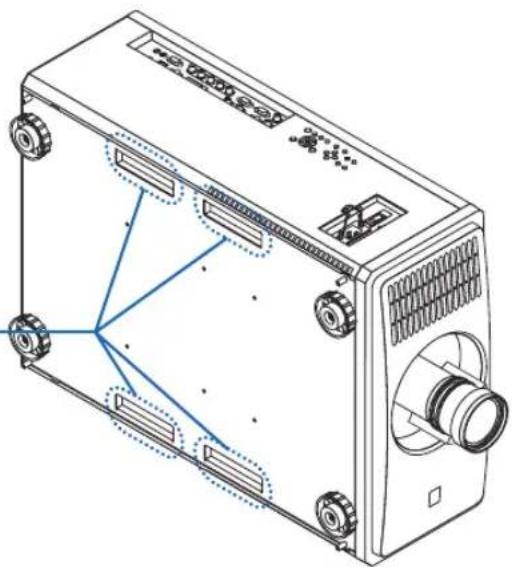
natural_image
Technical line drawing of a mechanical device with mounting holes and internal components (no text or symbols)Controls/Indicator Panel

- (POWER) Button
(→ page 16, 29)
- POWER Indicator
(→ page 16, 29, 89)
- STATUS Indicator
(→ page 89)
- LIGHT Indicator
(→ page 89)
- TEMP. Indicator
(→ page 89)
- INPUT Button
(→ page 19)
- AUTO ADJUST Button
(→ page 53)
- ASPECT Button
(→ page 50)
- HOME Button
(→ page 16, 22)
- SHUTTER Button
(→ page 33)
- MENU Button
(→ page 44)
- ▲▼◀▶ Buttons
(→ page 44)
- ENTER Button
(→ page 44)
- EXIT Button
(→ page 44)
- SHIFT ▲▼◀▶ Button
(→ page 21)
- FOCUS +/- Button
(→ page 24, 25)
- ZOOM +/- Button
(→ page 24, 26)
Terminals Features
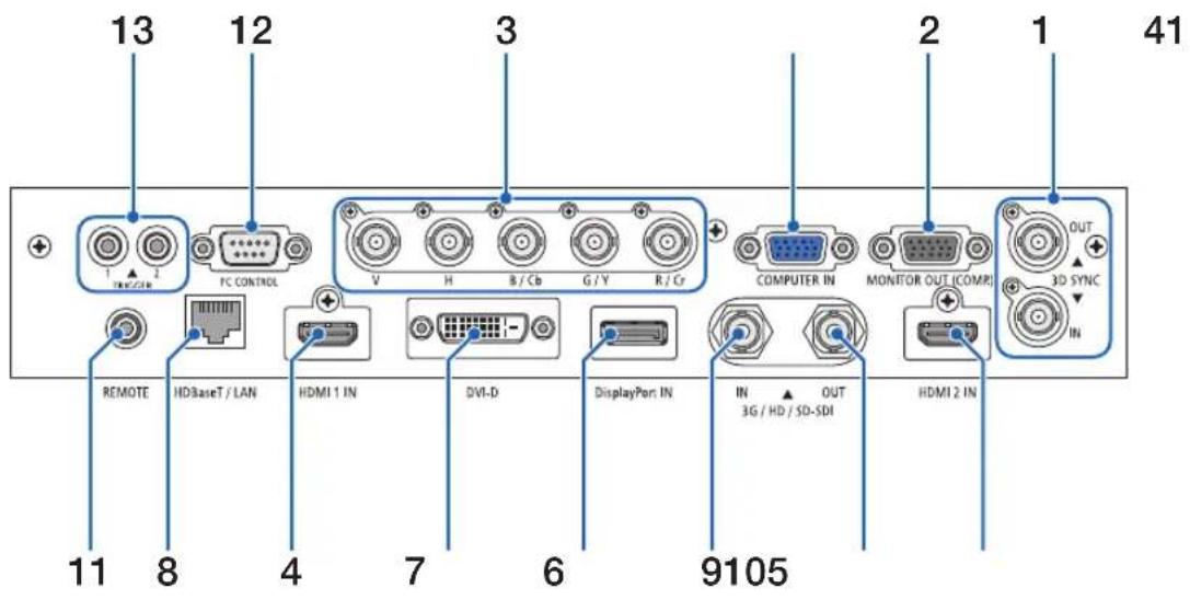
- COMPUTER IN Terminal (Mini D-Sub 15 Pin)
$$ (\rightarrow \text { page 71 }) $$
-
MONITOR OUT Terminal (Mini D-Sub 15 Pin)
-
BNC IN [R/Cr/CV, G/Y/Y, B/Cb/C, H, V] Terminals (BNC × 5)
$$ (\rightarrow \text { page } 7 1) $$
- HDMI 1 IN Terminal (Type A)
$$ (\rightarrow \text { page } 1 3, 7 1) $$
- HDMI 2 IN Terminal (Type A)
$$ (\rightarrow \text { page } 1 3, 7 1) $$
- 3G/HD/SD-SDI OUT Terminal (BNC)
$$ (\rightarrow \text { page } 7 1) $$
- REMOTE Terminal (Stereo Mini)
Use this jack for wired remote control of the projector using a commercially available remote cable with ∅3.5 stereo mini-plug (without resistance).
Connect the projector and the supplied remote control using a commercially available wired remote control cable.
$$ (\rightarrow \text { page } 1 1) $$
NOTE:
- When a remote control cable is connected to the REMOTE terminal, infrared remote control operations cannot be performed.
- Power cannot be supplied from the REMOTE terminal to the remote control.
- When [HDBaseT] is selected in the [REMOTE SENSOR] and the projector is connected to a commercially-available transmission device that supports HDBaseT, remote control operations in infra-red cannot be carried out if transmission of remote control signals has been set up in the transmission device. However, remote control using infrared rays can be carried out when the power supply of the transmission device is switched off.
12. PC CONTROL Port (D-Sub 9 Pin)
Use this port to connect a PC or control system. This enables you to control the projector using serial communication protocol. Use a shielded RS232C cable (sold commercially).
$$ (\rightarrow \text { page 85 }) $$
13. TRIGGER 1/2 Terminal (Stereo Mini)
$$ (\rightarrow \text { page 86 }) $$
NOTE:
- Do not use the TRIGGER 1/2 terminal for anything other than intended use. Connecting the wired remote control to the TRIGGER 1/2 terminal causes damage to the remote control.
14. 3D SYNC Terminal (Mini DIN 3 Pin)
$$ (\rightarrow \text { page } 5 2) $$
1-4. Part Names of the Remote Control
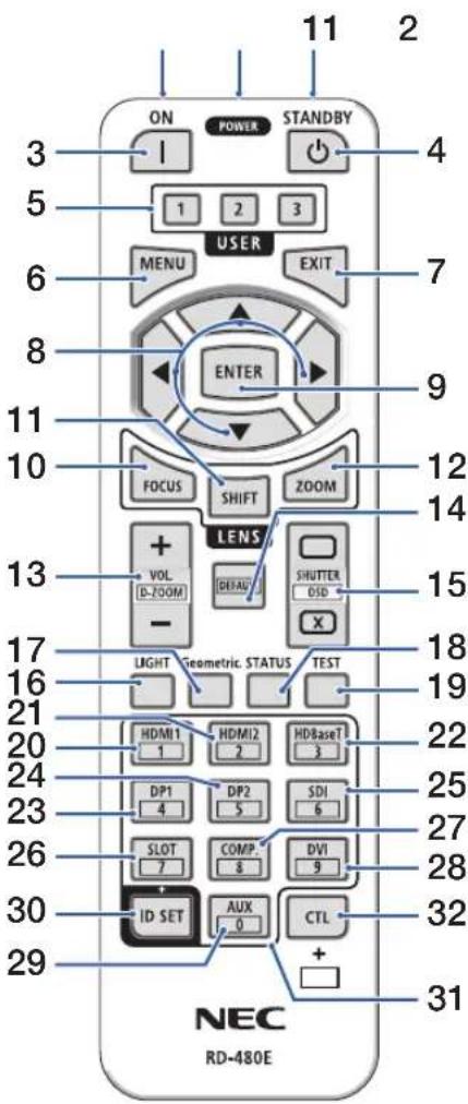
1. Infrared Transmitter
(→ page 11)
2. Remote Jack
Connect a commercially available remote cable here for wired operation. (→ page 11)
3. POWER ON Button ( )
(→ page 16)
4. POWER STANDBY Button ( )
(→ page 29)
5. USER 1/2/3 Button
(Not available on this series of projectors. For future expansion)
6. MENU Button
(→ page 44)
7. EXIT Button
(→ page 44)
8. ▲▼◀▶ Button
(→ page 44)
9. ENTER Button
(→ page 44)
10. FOCUS Button
(→ page 24, 25)
11. SHIFT Button
(→ page 21)
12. ZOOM Button
(→ page 24, 25)
13. VOL./D-ZOOM (+)(−) Button
(The VOL. button function cannot be used with this series of projectors.)
(→ page 32)
14. DEFAULT Button
(Not available on this series of projectors. For future expansion)
15. SHUTTER/OSD OPEN (C)
CLOSE (Button
(→ page 30)
16. LIGHT Button
(→ page 33)
17. Geometric. Button
(→ page 34)
18. STATUS Button
(→ page 70)
19. TEST Button
(→ page 23, 51)
20. HDMI1 Button
(→ page 18)
21. HDMI2 Button
(→ page 18)
22. HDBaseT Button
(→ page 18)
23. DP1 Button
(→ page 18)
24. DP2 Button
(Not available on this series of projectors.)
25. SDI Button
(→ page 18)
26. SLOT Button
(Not available on this series of projectors.)
27. COMP. Button
(→ page 18)
28. DVI Button
(→ page 18)
29. AUX Button
(→ page 18)
30. ID SET Button
(→ page 68)
31. Numeric Keypad Button
(→ page 68)
32. CTL Button
(→ page 30, 32)
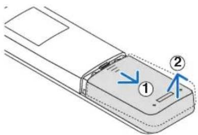
Battery Installation
-
Press the catch and remove the battery cover.
-
Install new ones (AAA). Ensure that you have the batteries' polarity (+/-) aligned correctly.
-
Slip the cover back over the batteries until it snaps into place.
NOTE:
- Do not mix different types of batteries or new and old batteries.

natural_image
Technical line drawing of a remote control panel with two batteries and a switch (no text or symbols)
Remote Control Precautions
- Handle the remote control carefully.
- If the remote control gets wet, wipe it dry immediately.
- Avoid excessive heat and humidity.
- Do not short, heat, or take apart batteries.
- Do not throw batteries into fire.
- If you will not be using the remote control for a long time, remove the batteries.
- Ensure that you have the batteries' polarity (+/-) aligned correctly.
- Do not use new and old batteries together, or use different types of batteries together.
- Dispose of used batteries according to your local regulations.
- Please note that if multiple projectors are installed nearby, other projectors may unintentionally light up when you turn on the power using the remote control.
Operating Range for Wireless Remote Control
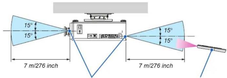
Remote control Remote sensor on proj

- The infrared signal operates by line-of-sight up to a distance of above meters and within a 60-degree angle of the remote sensor on the projector cabinet.
- The projector will not respond if there are objects between the remote control and the sensor, or if strong light falls on the sensor. Weak batteries will also prevent the remote control from properly operating the projector.
Using the Remote Control in Wired Operation
Connect one end of the remote cable to the REMOTE terminal and the other end to the remote jack on the remote control.

NOTE:
- When a remote cable is inserted into the REMOTE terminal, the remote control does not work for infrared wireless communication.
- Power will not be supplied to the remote control by the projector via the REMOTE jack. Battery is needed when the remote control is used in wired operation.
- Connecting the wired remote control to the TRIGGER 1/2 terminal causes damage to the remote control.
2. Projecting an Image (Basic Operation)
This section describes how to turn on the projector and to project a picture onto the screen.
2-1. Flow of Projecting an Image
Step 1
- Connecting your computer / Connecting the power cord (→ page 13)

Step 2
- Turning on the projector (→ page 15)

Step 3
- Selecting a source ( page 18)

Step 4
- Adjusting the picture size and position (→ page 20)
- Correcting keystone distortion [KEYSTONE] (→ page 34, 58)

Step 5
- Adjusting a picture

Step 6
- Making a presentation

Step 7
- Turning off the projector (→ page 29)
2-2. Connecting Your Computer/Connecting the Power Cord
1. Connect your computer to the projector.
This section will show you a basic connection to a computer. For information about other connections, see “5-1. Connecting to Other Equipment” on page 71.
Connect the HDMI output terminal of the computer to the HDMI 1 IN or HDMI 2 IN input terminal of the unit.
2. Connect the supplied power cord to the projector.

WARNING
MAKE SURE TO TAKE THE GROUND CONNECTION FOR THE DEVICE. TO PREVENT FIRE OR SHOCK, DO NOT EXPOSE THIS UNIT TO RAIN OR MOISTURE. DO NOT USE THIS UNIT'S PLUG WITH AN EXTENSION CORD OR IN AN OUTLET UNLESS ALL THE PRONGS CAN BE FULLY INSERTED.

CAUTION
This equipment is designed to be used in the condition of the power cord connected to earth. If the power cord is not connected to the earth, it may cause electric shock. Please make sure the power cord is earthed properly. Do not use a 2-core plug converter adapter.
Important Information:
- When plugging in or unplugging the supplied power cord, make sure that the main power switch is pushed to the off [O] position. Failure to do so may cause damage to the projector.
- Do not use a three-phase power supply. Doing so may cause of malfunction.
First connect the supplied power cord's three-pin plug to the AC IN terminal of the projector, and then connect the other plug of the supplied power cord in the wall outlet. Do not use any plug converter.


CAUTION
Parts of the projector may become temporarily heated if the projector is turned off with the POWER button or if the AC power supply is disconnected during normal projector operation.
Use caution when picking up the projector.
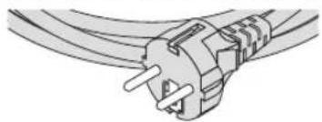
Using the Supplied Power Cords
Select the power cord suitable for your country or region.
For Europe/Asia/South America For North America
natural_image
Pure electrical circuit lines without any symbols
natural_image
Illustration of a power cord with two terminal leads (no text or symbols)Using the Power Cord Stopper
To prevent the power cord from accidentally removing from the AC IN of the projector, attach the power cord stopper to clamp the power cord.

CAUTION
- To prevent the power cord from coming loose, make sure that all the prongs of the power cord are fully inserted into the AC IN terminal of the projector before using the power cord stopper to fix the power cord. A loose contact of the power cord may cause a fire or electric shock.
Attaching the power cord stopper
- Raise up the power cord stopper and lay it over the power cord.
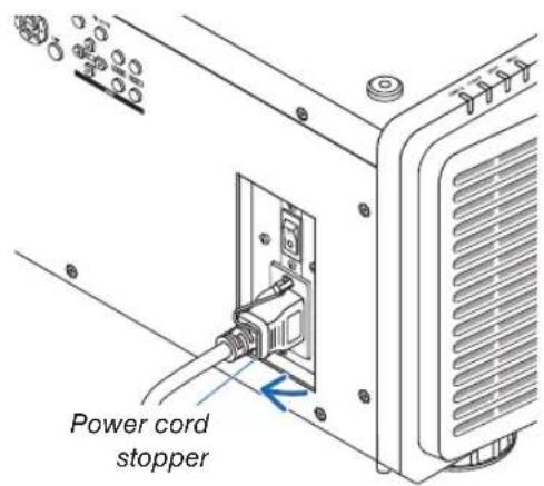
- For releasing the stopper, raise up the stopper and lay it down to the opposite side.

natural_image
Line drawing of an electronic device showing a cable inserted into a socket (no text or symbols)2-3. Turning on the Projector
NOTE:
- The projector has two power switches: A main power switch and a POWER button (POWER ON and POWER ON on the remote control)
-
Turning on the projector:
-
Press the main power switch to the ON position (I).
The projector will go into standby mode.
- Press the POWER button.
The projector will become ready to use.
- Turning off the projector:
- Press the POWER button.
The confirmation message will be displayed.
- Press the POWER button again.
The projector will go into standby mode.
- Press the main power switch to the OFF position (O).
The projector will be turned off.
- Remove the lens cap from the lens unit.
NOTE:
- Do not leave the lens cap on the lens while the projector is operating. The lens cap could get hot and become warped.
- Press the main power switch to the ON position (I).
POWER indicator lights up in green. (When the [STANDBY POWER] is set to [ON] in the on-screen menu)
(→ page 65)

natural_image
Technical line drawing of a projector unit with a close-up view showing the internal components and a hand interacting with the screen (no text or symbols present)- Press the ⓊPOWER) button on the projector cabinet or the POWER ON button on the remote control.

WARNING
The projector produces a strong light. When turning on the power, operate from the side or rear of the projector (outside the Restriction Zone (HD)). Also, when turning on the power, make sure no one within the projection range is looking at the lens.
The POWER indicator goes from a steady green light to a flashing blue light, and the picture is projected on the screen.
After you turn on your projector, ensure that the computer or video source is turned on.
NOTE:
- The blue screen ([BLUE] background) is displayed when no signal is being input (by factory default menu settings).
Performing Lens Calibration
After installation or replacement of the lens, be sure to perform [CENTER LENS] by pressing and holding the HOME button on the projector cabinet for at least two seconds. Perform [CENTER LENS] also when trouble is found on the lens shift motion. Calibration corrects the adjustable lens shift range. Also, perform [CENTER LENS] when an error occurs in the lens shift operation. ( page 22)

Standby Blinking Power On

About the language of the on-screen menu
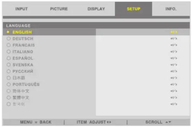
When you turn on the power for the first time after purchase, the on-screen menu is displayed in English. The display language of the on-screen menu can be changed by selecting [SETUP] → [LANGUAGE] on the on-screen menu.
- If one of the following things happens, the projector will not turn on.
- If the internal temperature of the projector is too high, the projector detects abnormal high temperature. In this condition the projector will not turn on to protect the internal system. If this happens, wait for the projector's internal components to cool down.
- If the STATUS indicator lights orange with the POWER button pressed, it means that the [CONTROL PANEL LOCK] is turned on. Cancel the lock by turning it off. (→ page 69)
- While the POWER indicator is blinking blue in short cycles, the power cannot be turned off by using the POWER button.
2-4. Selecting a Source
Selecting the computer or video source
NOTE:
- Turn on the computer or video source equipment connected to the projector.
Using the Direct button on the remote control
Press the Direct button on the remote control.
Select the input according to the connection terminal.

| Input connector Button on the remote control | |
| HDMI 1 IN HDMI1 | |
| HDMI 2 IN HDMI2 | |
| DisplayPort IN DP1 | |
| DVI-D DVI | |
| 3G/HD/SD-SDI IN SDI, AUX | |
| HDBaseT/LAN HDBaseT | |
| COMPUTER IN COMP. | |
| BNC IN CTL + DP1 | |
Using the INPUT button on the projector cabinet
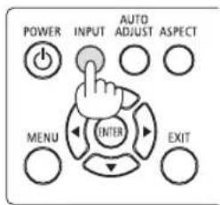
Pressing the INPUT button will switch to the next input source.
HDMI 1 → HDMI 2 → COMPUTER → BNC → DVI-D → DisplayPort → SDI → HDBaseT.....
Select by displaying the On-Screen Menu
- Press the MENU button.
The On-Screen Menu will be displayed on. - Move the cursor by the ◀ or ▶ button to the [INPUT].
- Move the cursor by the ▼ or ▲ button to the [INPUT SELECTION] and then press the ENTER or ▶ button.
| INPUT | PICTURE | DISPLAY | SETUP | INFO. |
| INPUT SELECTION | HDMI 1 | ### | ||
| AUTO SOURCE | OFF | <> | ||
| COLOR SPACE | AUTO | <> | ||
| ASPECT RATIO | AUTO | <> | ||
| OVERSCAN | OFF | <> | ||
| IMAGE OPTIONS | ### | |||
| TEST PATTERN | ### | |||
| 3D | ### | |||
| AUTO ADJUST | ### | |||
| MENU = BACK | ITEM ADJUST <> | SCROLL >> | ||||

- Press the ▼ or ▲ button, select the input source, and press the ENTER or ▶ button.

2-5. Adjusting the Picture Size and Position
In this chapter drawings and cables are omitted for clarity.
Adjusting the projected image's vertical and horizontal position[Lens shift](→ page 21) | Adjusting the focus[Focus](→ page 24, 25)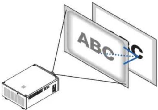 |
Finely adjusting the size of an image[Zoom](→ page 24, 26) | Adjusting the projected image's height and horizontal tilt [Tilt foot]*1(→ page 28) |
NOTE\*1:
- Adjust the projected image's height using the tilt foot when you want to project the image at a position higher than the lens shift adjustment range.
TIP:
- Built-in test patterns can be conveniently used for adjusting the picture size and position. (→ page 51) A press of the TEST button will display the test pattern. The ◀ or ▶ button can select one test pattern. To close the test pattern, change the source to another.
Adjusting the vertical position of a projected image (Lens shift)

CAUTION
- Perform the adjustment from behind or from the side of the projector. If adjustments are performed from the front, your eyes could be exposed to strong light and get injured.
- Keep hands away from the lens mounting portion while performing a lens shift. Failure to do so could result in fingers being pinched by the moving lens.
NOTE:
- Shifting the lens to the maximum in oblique angle will cause the edges of the image to become dark or will cause dark shadows.
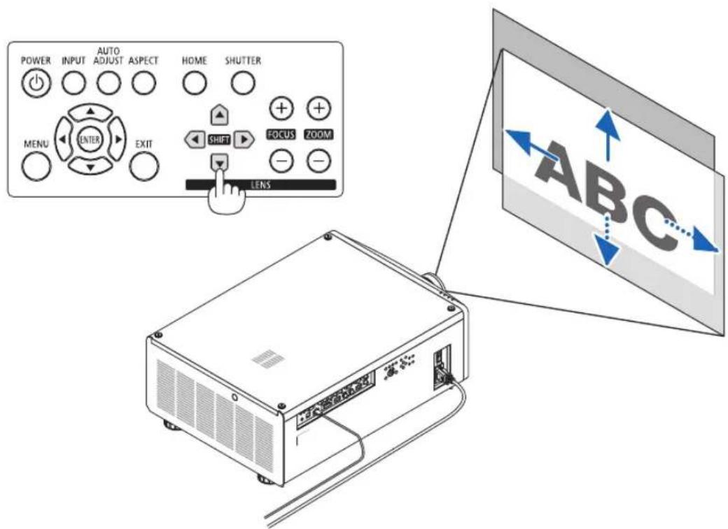
Adjusting with buttons on the cabinet
1. Press the SHIFT ▼▲◀ or ▶ button.
Use the SHIFT ▼▲◀▶ buttons to move the projected image.
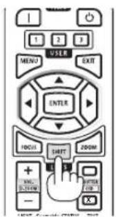
Adjusting with the remote control
1. Press the SHIFT button.
The [LENS CONTROL] screen will be displayed.
![LENS CONTROL SHIFT [ENTER] CHANGE ADJUSTMENT](/content/2026/06/1249348/images/70341a312ac2813bb39e9f5522b8ad97d0349a8d90d34b4fae5b2fcd87c85741.jpg)
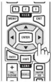
2. Press the ▼▲◀ or ▶ button.
Use the ▼▲◀▶ buttons to move the projected image.
NOTE:
About [CENTER LENS]
If the power of the projector is wrongly shut down during the motion of lens shift, it may shift the home position of the lens and may cause of malfunction. The STATUS indicator flashed in Orange to inform this kind of trouble occurrence. In this case, perform [CENTER LENS].
Operating procedure
- Power on the projector.
- Press the HOME button.
[CENTER LENS] is executed.
TIP:
- The diagram below shows the lens shift adjustment range (projection mode: [DESKTOP FRONT]). To raise the projection position higher than this, adjust by the tilt foot. ( page 28) * NP45ZL only ± 45% V
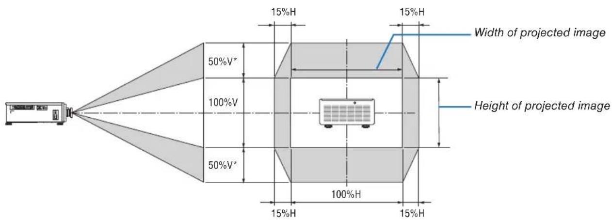
Description of symbols: V indicates vertical (height of the projected image), H indicates horizontal (width of the projected image).
Adjusting the focus and zoom of the projected image
Adjust the focus and size of the projected image.
The adjustment procedure differs depending on the lens unit that you are using.
Recommend to perform the focus adjustment after leaving the projector under the state the TEST PATTERN has been projected for over 30 minutes.
TIP:
- To obtain the best focus, perform the following (for permanent installation)
Preparation: Warm up the projector for one hour.
-
Use the FOCUS (+) or (−) buttons to make sure you obtain the best focus. If you do not, move the projector back and forth.
-
Select the [TEST PATTERN] from the menu and display the test pattern. (→ page 51)
- You can also use the TEST button on the remote control to display the test pattern.
-
Press the FOCUS (−) button until the pixel lattice of the test pattern cannot be seen any more.
-
Keep pressing the FOCUS (+) button until you obtain the best focus.
If you adjust beyond the best focal point, go back to step 3 and repeat the procedures.
Applicable lens: NP48ZL/NP49ZL
1. Adjust the focus until the image is clear.
Adjusting with buttons on the cabinet
Use the FOCUS (+) or (−) button on the projector cabinet.

Adjusting with the remote control
① Press the FOCUS button or the ZOOM button.
The test pattern and the [LENS CONTROL] screen will be displayed on.
![LENS CONTROL ZOOM FOCUS [ENTER] CHANGE ADJUSTMENT](/content/2026/06/1249348/images/cf4ded28211204d7b323752581cab17b1ed8188d0cdfed7152df9d7233ac9f69.jpg)
② Press the ◀/▶ buttons.
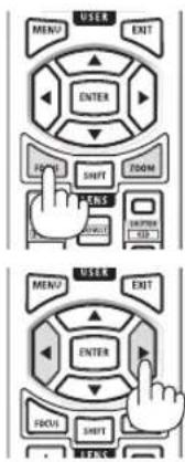
2. Adjust the zoom until the projected image fits the screen.
Adjusting with buttons on the cabinet
Use the ZOOM (+) or (−) button on the projector cabinet.
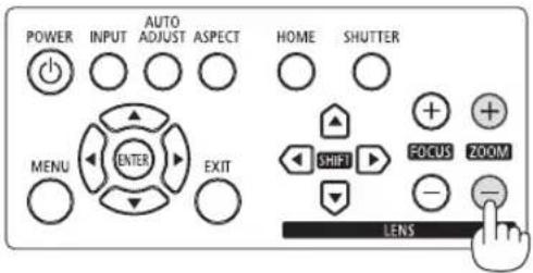
Adjusting with the remote control
Press the ▲/▼ buttons.
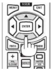
- Adjust the focus again with the same procedure as Step 1 to make fine adjustments to the focus.
Applicable lens: NP45ZL/NP46ZL/NP47ZL
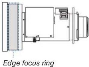
The lens unit NP45ZL, NP46ZL, or NP47ZL allows you to manually adjust the edge focus in addition to the electric focus.
Edge focus position for each lens unit
| NP45ZL NP46ZL NP47ZL | ||
 |  |  |
1. Focus on the projected image around the optical axis. (Powered focus)
Adjusting with buttons on the cabinet
Use the FOCUS (+) or (−) button on the projector cabinet.

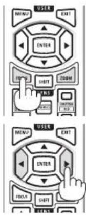
Adjusting with the remote control
① Press the FOCUS button or the ZOOM button.
The test pattern and the [LENS CONTROL] screen will be displayed on.
![LENS CONTROL ZOOM FOCUS [ENTER] CHANGE ADJUSTMENT](/content/2026/06/1249348/images/4878ed32b0e6167b90b2abf24d87ab5a79ba79f88aaa8a771631c5f61e8b054f.jpg)
② Press the ◀/▶ buttons.
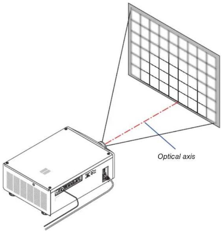
* With the lens shift in the center position the optical axis is at the center of the image. In this case, adjust the focus at the center of the projected image.

natural_image
Grid pattern with uniform squares (no text or symbols)- Adjust the zoom until the projected image fits the screen.
Adjusting with buttons on the cabinet
Use the ZOOM (+) or (−) button on the projector cabinet.

Adjusting with the remote control Press the ▲/▼ buttons.

- Follow the same procedure as in Step 1 to make fine adjustments to the focus near the optical axis. (Powered focus)
Continue to next page
4. Adjust the focus at the edges of the projected image. (Manual focus)
Turn the edge focus ring clockwise or counterclockwise.
In this case the focus near the optical axis adjusted in the step 1 and step 3 will not be changed.

Adjusting the Tilt Foot
- The position to project image may be adjusted by the tilt foot positioned at four corners of the cabinet bottom.
The tilt foot height can be adjusted by its turn.
"To adjust the height of the projected image"
The height of the projected image is adjusted by turning either front or rear tilt foot.
"If the projected image is tilted"
If the projected image is tilted, turn either left or right tilt foot to adjust the image so that it is level.
- If the projected image is distorted, see "3-8. Correcting Horizontal and Vertical Keystone Distortion [KEYSTONE]" (→ page 34) and "[GEOMETRIC CORRECTION]" (→ page 58).
- The tilt foot can be lengthened by a maximum of 10 mm/0.4".
- The tilt foot can be used to tilt the projector by a maximum of 1^ .
NOTE:
- Do not lengthen the tilt foot any more than 10 mm/0.4". Doing so will make the tilt feet's mount section unstable and could cause the tilt feet to come off the projector.
- Pay attention to lengthen or shorten two tilt foot at front at the same time. Same for the rear foot, otherwise, the weight of the projector is loaded on one side and it may cause of damage to it.
- Do not use the tilt foot for any purpose other than adjusting the projector's projection angle.
Handling the tilt foot improperly, such as carrying the projector by grasping the tilt foot or hooking it onto a wall using the tilt foot, could damage the projector.

Tilt foot
(there is one more in the rear)
2-6. Turning off the Projector
1. Press the ⓊPOWER) button on the projector cabinet or the POWER STANDBY button on the remote control.
The [POWER OFF] message will appear.
POWER OFF ARE YOU SURE ?
2. Press the ⏻POWER) button again.
The light source will be turned off and the power supply will be cut. The projector will go to standby mode and the POWER indicator will light in green.
- If using the remote control, press the POWER STANDBY button again.
- If you do not want to turn the power off, press the EXIT button.
3. Make sure the projector is in STANDBY MODE, then turn off the main power switch "○ (OFF)"
The POWER indicator will go off and the main power will turn off.
- While the POWER indicator is blinking blue in short cycles, the power cannot be turned off.


natural_image
Line drawing of a device with a hand pressing a button, showing internal components and wiring (no text or symbols)
CAUTION:
Parts of the projector may temporarily overheat if the projector is turned off with the main power switch or the AC power supply is disconnected while the projector is in operation or the cooling fan is running. Handle with care.
NOTE:
- Do not unplug the power cord from the projector or from the power outlet while an image is being projected. Doing so could deteriorate the projector's AC IN terminal or the power plug's contact. To turn off the AC power supply when the projector is powered on, use the projector's main power switch, a power strip equipped with a switch, or a breaker.
- Do not turn off the main power switch or disconnect the AC power supply within 10 seconds of making adjustments or setting changes and closing the menu. Doing so can cause loss of adjustments and settings.
3. Convenient Features
3-1. Turn off the light of the projector (LENS SHUTTER)
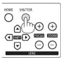
Press the SHUTTER button.
The light source will turn off temporarily.
Press again to allow the screen to become illuminated again.
- Press the SHUTTER CLOSE ( ) button on the remote control. Press the SHUTTER OPEN ( ) button to allow the screen to become illuminated again.

TIP:
- The video will disappear but not the menu display.
3-2. Turning Off the On-Screen Menu (On-Screen Mute)
Hold down the CTL button on the remote control and press the OSD CLOSE (O) button.
The on-screen menu, input terminal, etc. will disappear.
- To display the on-screen display, press the OSD OPEN (☐) button while holding down the CTL button on the remote control.

TIP:
- To confirm that the on-screen mute is turned on, press the MENU button. If the on-screen menu is not displayed even though you press the MENU button, it means the on-screen mute is turned on.
- The on-screen mute is maintained even when the projector is turned off,
- Holding down the MENU button on the projector cabinet for at least 10 seconds will turn off the on-screen mute.
3-3. Shift the On-Screen Menu displaying position
- Press the MENU button.
The On-Screen Menu will be displayed on.
- Move the cursor by the ▶ button to the [SETUP].
- Move the cursor by the ▼ or ▲ button to the [MENU] and then press the ENTER or ▶ button.
| INPUT | PICTURE | DISPLAY | SETUP | INFO. |
| LANGUAGE | ENGLISH | +/-> | ||
| ORIENTATION | DESKTOP FRONT | +/-> | ||
| FAN MODE | AUTO | +/-> | ||
| AUTO POWER OFF | OFF | <-> | ||
| DIRECT POWER ON | OFF | <-> | ||
| NETWORK SETTINGS | +/-> | |||
| LIGHT MODE | +/-> | |||
| BACKGROUND | BLUE | +/-> | ||
| STARTUP LOGO | ON | <-> | ||
| REMOTE CONTROL | +/-> | |||
| TRIGGER-1 | OFF | <-> | ||
| TRIGGER-2 | OFF | <-> | ||
| MENU | +/-> | |||
| MENU = BACK | ITEM ADJUST <> | SCROLL ▲▼ | ||||
- Move the cursor to [MENU POSITION] and press the ENTER or ▶ button.
| INPUT | PICTURE | DISPLAY | SETUP | INFO. |
| MENU | ||||
| MENU POSITION | CENTER | ### | ||
| MENU TRANSLUCENT | 0 | ### | ||
| DISPLAY TIME | AUTO 45 SEC | ### | ||
| MESSAGE DISPLAY | ON | ### | ||
| CONTROL PANEL LOCK | OFF | ### | ||
| MENU = BACK | ITEM ADJUST ↔ | SCROLL ▲▼ | ||||
- Press the ▼▲ button, select the menu position, and press the ENTER or ▶ button.
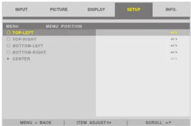
For finishing the setting on the On-Screen Menu, press the MENU button on the remote control.
TIP:
- The display position of the menu is saved even when the power supply of the projector is turned off.
- This function does not influence to the display position of input terminal information and message.
3-4. Magnifying a Picture
You can magnify the picture up to two times.
NOTE:
- Depending on an input signal, the maximum magnification may be less than two times, or the function may be restricted.
To do so:
- Press and hold the CTL button and then press VOL./D-ZOOM (+) button on the remote control to magnify the picture.

natural_image
Isometric illustration of a two-story house with a gabled roof and window (no text or symbols)


natural_image
Architectural line drawing of a two-story building with balconies and a chimney (no text or symbols)- Press and hold the CTL button and then press VOL./D-ZOOM (−) button on the remote control.
Each time the button is pressed, the image is reduced.
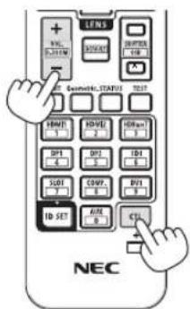
NOTE:
- The image will be magnified or demagnified at the center of the screen.
3-5. Adjustment of luminance (brightness) and energy-saving effect [LIGHT MODE]
The brightness of the projector can be adjusted within a range of 30 to 100% (in 1% increments) and maintained at a constant level after adjusting. In addition, when you set the [LIGHT MODE] to [ECO], the brightness decreases and the operating sound gets quieter. As a result, the power consumption can be reduced.
Use [LIGHT MODE], [LIGHT ADJUST] and [CONSTANT BRIGHTNESS] at [LIGHT MODE] under the [SETUP] menu in the on-screen menu. (→ page 66)
| Function name Description | ||
| LIGHT MODE Adjusts the output of the light source of the projector. | ||
| NORMAL Brightness changes to 100% and the screen becomes bright. | ||
| ECO The brightness becomes about 80% of the brightness in the [NORMAL] mode. The operating noise and power consumption will also decrease due to control of the cooling fan according to the brightness. | ||
| LIGHT ADJUST | When the mode is set to [NORMAL] in [LIGHT MODE], the brightness can be adjusted within a range of 30 to 100% (in 1% increments). | |
| NOTE:When using the NP49ZL lens unit, brightness can be adjusted within a range of 30% to 87%. | ||
| CONSTANT BRIGHTNESS | Controls the brightness to keep it constant based on the brightness at the time of switching to [ON]. The adjustment value will be saved until [CONSTANT BRIGHTNESS] is set to [OFF] even if the power is turned off. | |
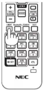
- Press the LIGHT button on the remote control.
The [LIGHT MODE] screen will be displayed.
- Press ▲▼ button to select the [MODE] and press the ENTER or ▶ button.
3-6. Correcting Horizontal and Vertical Keystone Distortion [KEYSTONE]
Use the [KEYSTONE] feature to correct keystone (trapezoidal) distortion to make the top or bottom and the left or right side of the screen longer or shorter so that the projected image is rectangular.
- Press the Geometric. button.
Display the [GEOMETRIC CORRECTION] screen of the on-screen menu.
- Press the ▼/▲ button to select [KEYSTONE] and press the ENTER or ▶ button.
The [KEYSTONE] menu screen will displayed on.
- Move the cursor to [HORIZONTAL] or [VERTICAL], then press the ◀/▶ button to adjust the projection screen.
![SHARP PX2201UL - 3-6. Correcting Horizontal and Vertical Keystone Distortion [KEYSTONE] - 1](/content/2026/06/1249348/images/ce0657fc5166882e9794417c88e63f0086c646d71588e673b21c526c3a7e69aa.jpg)
natural_image
Simple diagram showing a light blue parallelogram transforming into a light blue rectangle with an arrow (no text or symbols)TIP:
- For details on the [GEOMETRIC CORRECTION] menu functions, see (→ page 58).
NOTE:
- Use horizontal keystone correction when the vertical lens shift position is near 0 V. Other than the above cases, use [TOP LEFT CORNER], [TOP RIGHT CORNER], [BOTTOM LEFT CORNER], or [BOTTOM RIGHT CORNER] to correct the keystone distortion.
3-7. Controlling the Projector by Using an HTTP Browser
Overview
Using the web browser on the computer, the HTTP server screen of the projector can be displayed to operate the projector.
Possible operations on the HTTP server screen
- Configure the settings required for connecting the projector to the network (wired LAN).
- Operate the projector.
Operations such power on/off of the projector, input terminal switchover, and lens control etc. can be carried out.
- Configure the HTTP SERVER, PC CONTROL, CRESTRON, and PJLink PASSWORD etc.
To view the HTTP server screen
- Connect the projector to the computer with a LAN cable sold commercially. ( page 71)
- Select [SETUP] → [NETWORK SETTINGS] in the on-screen menu to configure the network settings. (→ page 65)
- Start up the web browser on your computer and enter the address or URL in the input field.
Specify the address or URL as "http://
The HTTP server screen will be displayed.
TIP:
- The factory setting IP address is [DHCP ON].
NOTE:
- To use the projector in a network, consult with your network administrator about network settings.
- The display's or button's response can be slowed down or operation may not be accepted depending the settings of your network. Should this happen, consult your network administrator. The projector may not respond if its buttons are repeatedly pressed in rapid intervals. Should this happen, wait a moment and repeat. If you still can't get any response, turn off and back on the projector.
- If the PROJECTOR NETWORK SETTINGS screen does not appear in the web browser, press the Ctrl+F5 keys to refresh your web browser (or clear the cache).
- This projector uses “JavaScript” and “Cookies” and the browser should be set to accept these functions. The setting method will vary depending on the version of browser. Please refer to the help files and the other information provided in your software.
Preparation before Use
Connect the projector to a commercially available LAN cable before engaging in browser operations. ( page 71) Operation with a browser that uses a proxy server may not be possible depending on the type of proxy server and the setting method. Although the type of proxy server will be a factor, it is possible that items that have actually been set will not be displayed depending on the effectiveness of the cache, and the contents set from the browser may not be reflected in operation. It is recommended that a proxy server not be used unless it is unavoidable.
Handling of the Address for Operation via a Browser
Regarding the actual address that is entered for the address or entered to the URL column when operation of the projector is via a browser, the host name can be used as it is when the host name corresponding to the IP address of the projector has been registered to the domain name server by a network administrator, or the host name corresponding to the IP address of the projector has been set in the "HOSTS" file of the computer being used.
Example 1: When the host name of the projector has been set to “pj.nec.co.jp”, access is gained to the network setting by specifying
http://pj.nec.co.jp/index.html
for the address or the entry column of the URL.
Example 2: When the IP address of the projector is “192.168.73.1”, access is gained to the network setting by specifying
http://192.168.73.1/index.html
for the address or the entry column of the URL.
3-8. Storing Changes for Lens Shift [LENS MEMORY]
Stores the projection position (lens shift) on the screen in the projector's memory. A maximum of 10 values can be stored. When you recall the stored [LENS MEMORY], the lens shift will automatically move at the adjustment value to move the position of the projection screen.
To store your adjusted values in [LENS MEMORY]:
- Adjust the projection position using the lens shift function of the projector.
- Press the MENU button.
The menu will be displayed.
- Press the ◀/▶ button to select [DISPLAY].
- Press the ▼/▲ button to select [LENS MEMORY] and press the ENTER or ▶ button.
The [LENS MEMORY] screen will be displayed.
- Press the ▼/▲ button to move the cursor to any of the items displayed as [STORE] on the right side in [MEMORY 1] to [MEMORY 10], then press the ENTER or ▶ button.
The lens shift adjustment value will be stored in the memory.
To call up your adjusted values from [LENS MEMORY]:
- Press the MENU button.
The menu will be displayed.
- Press the ◀/▶ button to select [DISPLAY].
- Press the ▼/▲ button to select [LENS MEMORY] and press the ENTER or ▶ button.
The [LENS MEMORY] screen will be displayed.
- Press the ▼/▲ button to move the cursor to any of the items displayed as [LOAD] on the right side in [MEMORY 1] to [MEMORY 10], then press the ENTER button.
The lens shift adjustment value will be recalled from [LENS MEMORY] and the lens shift will be automatically activated to move the position of the projection screen.
To delete your adjusted values from [LENS MEMORY]:
- Press the MENU button.
The menu will be displayed.
- Press the ◀/▶ button to select [DISPLAY].
- Press the ▼/▲ button to select [LENS MEMORY] and press the ENTER or ▶ button.
The [LENS MEMORY] screen will be displayed.
- Press the ▼/▲ button to move the cursor to any of the items displayed as [LOAD] on the right side in [MEMORY 1] to [MEMORY 10], then press the ▶ button.
The display changes from [LOAD] to [RESET].
- The setting switches between [RESET] and [LOAD] each time the ▶ button is pressed.
- Press the ENTER button.
The adjustment value in the memory will be deleted.
3-9. Adjust boundaries of a projected image [EDGE BLENDING]
This projector is equipped with an "EDGE BLENDING Function" that makes the edges (boundaries) of the projection screen indistinguishable.
NOTE:
- Before performing the EDGE BLENDING function, place the projector in the correct position so that the image becomes square in the appropriate size, and then make optical adjustments (lens shift, focus, and zoom).
- Adjust the brightness of each projector using [LIGHT ADJUST] under [SETUP]. In addition, adjust the picture quality with the various adjustment functions such as [PICTURE] → [PRESET] or [GAMMA CORRECTION] etc.
The following procedure shows an example of four projectors in a 2 × 2 layout.

Setting the overlap of projection screens
① Enable [EDGE BLENDING].
1. Press the MENU button.
The menu will be displayed.
2. Select [DISPLAY] → [EDGE BLENDING].
The [EDGE BLENDING] screen will be displayed. Align the cursor with [MODE] and then press the ENTER button. The mode screen will be displayed.
| INPUT | PICTURE | DISPLAY | SETUP | INFO. |
| LENS LOCK | OFF | +/-? | ||
| LENS CONTROL | ++/? | |||
| LENS MEMORY | ++/? | |||
| CENTER LENS | +/-? | |||
| DIGITAL ZOOM | ++/? | |||
| GEOMETRIC CORRECTION | +/-? | |||
| BLANKING | ++/? | |||
| EDGE BLENDING | ++? | |||
| SCREEN TYPE | 16:10 | ++/? | ||
| MENU = BACK | ITEM ADJUST ↔ | SCROLL ▲▼ | ||||
3. Select [MODE] → [ON] and press the ENTER button.
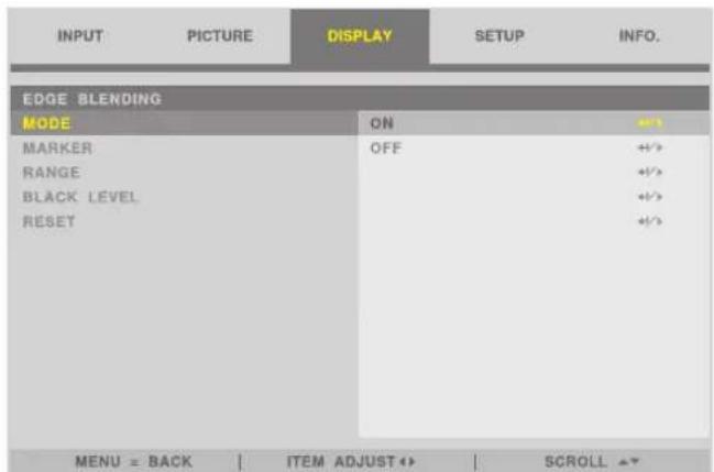
This enables the EDGE BLENDING function. The following menu items are available:
[MARKER], [RANGE], and [BLACK LEVEL]
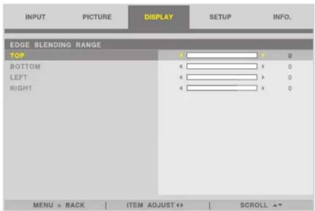

- Select [TOP], [BOTTOM], [LEFT], [RIGHT] after selecting [RANGE] or [BLACK LEVEL].
| TOP: OFFLEFT: OFF RIGHT: ONBOTTOM: ON | TOP: OFFLEFT: ON RIGHT: OFFBOTTOM: ON |
| TOP: ONLEFT: OFF RIGHT: ONBOTTOM: OFF | TOP: ONLEFT: ON RIGHT: OFFBOTTOM: OFF |
② Adjust [RANGE] to determine an area of overlapped edges of images projected from each projector.
When [MARKER] is set to [ON], markers of two colors are displayed on the screen according to the setting of [RANGE]. The red marker represent the edges of the region where images overlap, the green marker represent the range of overlapping (region/width).
![Turn on [RIGHT] Turn on [LEFT]](/content/2026/06/1249348/images/a92d291032406b99ed3d910ba05ee2b1e1bba69728667d99a94d34f6b4dc7a75.jpg)
* The 2 screens are separated in the diagram for explanatory purposes.
Adjust the overlapping area (width) with [RANGE]. In the case of the figure on the previous page, adjust the green marker on the left screen onto the red marker on the right screen, and the green marker on the right screen onto the red marker on the left screen. Adjustment is completed when the markers are stacked. Turn off [MARKER] to turn off the marker.
TIP:
- When displaying a signal with a different resolution, perform the Edge Blending function from the start.
- Setting of [MARKER] will not be saved and return to [OFF] when the projector is turned off.
- To display or hide the marker while the projector is running, turn on or off [MARKER] from the menu.
[BLACK LEVEL]
Adjust the brightness of the overlapped section on the screens. According to the necessity, adjust the brightness of the overlapped section on the screens by the [BLACK LEVEL].
- Set the [MODE] to [ON] for selecting [BLACK LEVEL].
Black Level Adjustment
This adjusts the black level of the overlapping area and the non-overlapping area of the multi-screen (EDGE BLENDING). Adjust the brightness level if you feel the difference is too large.
NOTE:
- Adjustable area varies depending on what combination of [TOP], [BOTTOM], [LEFT] and [RIGHT] in the [RANGE] or [BLACK LEVEL] are turned on.
The black level of the lower left projector is adjusted as shown in the figure.

1. Select [DISPLAY] → [EDGE BLENDING] → [BLACK LEVEL] and press the ENTER button.
The screen will switch to the black level adjustment screen.

2. Use the ◀ or ▶ to adjust the black level.
Do this for the other projector if necessary.

TIP: 9-segmented portions for Black Level adjustment
The black level of the center projector is adjusted as shown in the figure.

TIP:
- The edge blending width is the width set in the range.
• The [BLACK LEVEL] can be adjusted to make it brighter only.
4. Using On-Screen Menu
4-1. Basic operations of the on-screen menu
Display the on-screen menu to adjust the quality of the image projected by the projector and to switch the operation mode of the projector. Hereinafter, "on-screen menu" will be abbreviated to "menu".
NOTE:
- The menu screen in this manual may differ slightly from the actual one.
4-1-1. Configuration of the on-screen menu screen
To display the menu, press the MENU button on the projector or remote control. Press the EXIT button to close the menu.
This section describes how to view and operate the menu.
Preparation: Turn on the projector and project the image on the screen.
1. Press the MENU button.
- Press the EXIT button to cancel the menu.
- The display position of the menu on the screen can be changed. ("MENU POSITION" → page 31)

2. Press the ◀/▶ button.
The cursor will move to the main menu tab (INPUT PICTURE DISPLAY SETUP INFO.). When the main menu tab changes, the sub-menu also changes.
3. With the cursor on the main menu tab, press the ▼/▲ button.
The cursor will move to the sub-menu.
- To return to the main menu tab from the sub-menu, press the MENU button.
- Press the EXIT button to cancel the menu.
4. Press the ▼/▲ button to move the cursor to the sub-menu that you want.
The mark displayed at the right end of the sub-menu indicates a key operation.
| ◀ ▶ | Press the ◀/▶ button to select the setting value. |
| ↓ / ▶ | Press the ENTER button or ▶ button to continue selecting. |
5. Move the cursor to the sub-menu that you want, then press the ◀/▶ button or ENTER button.
- An additional sub-menu that is one layer deep may also be displayed.
In this case, move the cursor to the sub-menu with the ▼/▲ button, then press the ENTER button.
4-1-2. Adjustment bar
To change the value on the adjustment bar, press the ◀/▶ button.
When you press the ◀/▶ button, the menu screen disappears and an adjustment bar is displayed at the bottom of the screen.

Press the ◀/▶ button to adjust and MENU button to confirm.
4-1-3. Confirmation message
A confirmation message is displayed when you reset the adjustment value etc.

Press the ◀/▶ button to move the cursor to [OK] or [CANCEL], then press the ENTER button.
4-1-4. Changing the number
This section explains how to change the factory default IP address and subnet mask etc. in the network settings of the menu.
1. Press the MENU button and select [SETUP] → [NETWORK SETTINGS].
The [NETWORK SETTINGS] screen is displayed.
| INPUT | PICTURE | DISPLAY | SETUP | INFO. |
| NETWORK SETTINGS | ||||
| NETWORK MODE | LAN1 | +/-> | ||
| STANDBY POWER | ON | +/-> | ||
| DHCP | OFF | +/-> | ||
| IP ADDRESS | 192.168, 0, 10 | |||
| SUBNET MASK | 255.255.255, 0 | |||
| GATEWAY | 0, 0, 0, 0 | |||
| DNS | 0, 0, 0, 0 | |||
| AMX BEACON | OFF | +/-> | ||
| MAC ADDRESS | 00:16:23:01:02:0B | |||
| PROJECTOR NAME | PJ-5522AA | |||
| HOST NAME | pj-5522AA | |||
| MENU = BACK | ITEM ADJUST ↔ | SCROLL ▲▼ | ||||
- Press the ▼/▲ button to move the cursor to the [IP ADDRESS], then press the ENTER button.
- Press the ◀/▶ button to move the cursor to the value to change.
- Press the ▼/▲ button to change the value, then press the ENTER button.
- Press the ▲ button to increase the value. Press the ▼ button to decrease the value.
4-2. List of Menu Items
Some menu items are not available depending on the input source.
| TOP MENU SUB MENU FACTORY DEFAULT SELECTIONS | |||||
| INPUT | INPUT SELECTION HDMI 1 | HDMI 1 / HDMI 2 / COMPUTER / BNC / DVI-D / DisplayPort / SDI / HDBaseT | |||
| AUTO SOURCE OFF OFF / ON | |||||
| COLOR SPACE AUTO | AUTO / YPbPr / YCbCr / RGB-PC / RGB-VIDEO | ||||
| ASPECT RATIO AUTO | 5:4 / 4:3 / 16:10 / 16:9 / 1.88 / 2.35 / LETTERBOX / AUTO / NATIVE | ||||
| OVERSCAN OFF OFF / CROP / ZOOM | |||||
| IMAGE OPTIONS | H TOTAL 100 0-200 | ||||
| H START 100 0-200 | |||||
| H PHASE 100 0-200 | |||||
| V START 100 0-200 | |||||
| TEST PATTERN OFF | CROSS HATCH / COLOR BAR / CHECKER BOARD / V BURST / WHITE / RED / GREEN / BLUE / BLACK | ||||
| 3D | FORMAT AUTO | AUTO / OFF(2D) / SIDE BY SIDE(HALF) / TOP AND BOTTOM / FRAME SEQUENTIAL | |||
| EYE SWAP NORMAL NORMAL / REVERSE | |||||
| DLP® Link | OFF OFF / ON | ||||
| DARK TIME 1.95ms | 0.65ms / 1.3ms | / 1.95ms | |||
| SYNC DELAY | 0 | 0-200 | |||
| SYNC REFERENCE | EXTERNAL / INTERNAL (INFORMATION FOR 3D FRAME SEQUENTIAL) | ||||
| AUTO ADJUST | |||||
| PICTURE | PRESET | HIGH-BRIGHT | HIGH-BRIGHT / PRESENTATION / VIDEO | ||
| CONTRAST | 100 0-200 | ||||
| BRIGHTNESS | 100 0-200 | ||||
| SHARPNESS | 0 | 0-15 | |||
| COLOR | 100 0-200 | ||||
| HUE | 100 0-200 | ||||
| COLOR TEMPERATURE | NATIVE | 5400K / 6500K / 7500K / 9300K / NATIVE | |||
| COLOR GAMUT | NATIVE | REC709 / EBU / SMPTE / NATIVE | |||
| GAMMA CORECTION | 2.2 | 1.0 / 1.8 / 2.0 / 2.2 / 2.35 / 2.5 / S-CURVE / DICOM SIM. | |||
| WHITE BALANCE | CONTRAST R 100 0-200 | ||||
| CONTRAST G 100 0-200 | |||||
| CONTRAST B | 100 0-200 | ||||
| BRIGHTNESS R | 100 0-200 | ||||
| BRIGHTNESS G | 100 0-200 | ||||
| BRIGHTNESS B | 100 0-200 | ||||
| COLOR CORRECTION | RED | HUE | 100 0-200 | ||
| SATURATION | 100 0-200 | ||||
| GAIN | 100 0-200 | ||||
| GREEN | HUE | 100 0-200 | |||
| SATURATION | 100 0-200 | ||||
| GAIN | 100 0-200 | ||||
| BLUE | HUE | 100 0-200 | |||
| SATURATION | 100 0-200 | ||||
| GAIN | 100 0-200 | ||||
| CYAN | HUE | 100 0-200 | |||
| SATURATION | 100 0-200 | ||||
| GAIN | 100 0-200 | ||||
| MAGENTA | HUE | 100 0-200 | |||
| SATURATION | 100 0-200 | ||||
| GAIN | 100 0-200 | ||||
| YELLOW | HUE | 100 0-200 | |||
| SATURATION | 100 0-200 | ||||
| GAIN | 100 0-200 | ||||
| WHITE | RED GAIN | 100 0-200 | |||
| GREEN GAIN | 100 0-200 | ||||
| BLUE GAIN | 100 0-200 | ||||
| RESET | |||||
| NOISE REDUCTION | 0 | 0-3 | |||
| DYNAMIC CONTRAST | OFF OFF / ON | ||||
| LIGHT OFF TIMER | OFF OFF / 0.5S | / 1.0S / 1.5S / 2.0S / 3.0S / 4.0S | |||
| DISPLAY | LENS LOCK OFF OFF / ON | ||||
| LENS CONTROL | ZOOM | ||||
| FOCUS | |||||
| SHIFT | |||||
| LENS MEMORY | MEMORY 1 STORE / LOAD / RESET | ||||
| MEMORY 2 STORE / LOAD / RESET | |||||
| MEMORY 3 STORE / LOAD / RESET | |||||
| MEMORY 4 STORE / LOAD / RESET | |||||
| MEMORY 5 STORE / LOAD / RESET | |||||
| MEMORY 6 STORE / LOAD / RESET | |||||
| MEMORY 7 STORE / LOAD / RESET | |||||
| MEMORY 8 STORE / LOAD / RESET | |||||
| MEMORY 9 STORE / LOAD / RESET | |||||
| MEMORY 10 STORE / LOAD / RESET | |||||
| CENTER LENS | |||||
| DIGITAL ZOOM | DIGITAL ZOOM 0 | ||||
| DIGITAL PAN 0 | |||||
| DIGITAL SCAN 0 | |||||
| RESET | |||||
| GEOMETRIC CORRECTION | KEYSTONE | HORIZONTAL 0 -600-600 | |||
| VERTICAL 0 -400-400 | |||||
| ROTATION 0 -10-10 | |||||
| RESET | |||||
| ROTATION | ROTATION 0 -100-100 | ||||
| RESET | |||||
| PINCUSHION / BARREL | H PINCUSHION / BARREL 0 | -150 (PINCUSHION) <= (H,V) <= 300 (BARREL) | |||
| V PINCUSHION / BARREL 0 | -150 (PINCUSHION) <= (H,V) <= 300 (BARREL) | ||||
| H KEYSTONE | 0 | HORIZONTAL -60-60 | |||
| V KEYSTONE | 0 VERTICAL | 40-40 | |||
| ROTATION 0 -10-10 | |||||
| RESET | |||||
| ARC | TOP | 0 -150-150 | |||
| BOTTOM | 0 -150-150 | ||||
| LEFT | 0 -150-150 | ||||
| RIGHT | 0 -150-150 | ||||
| RESET | |||||
| TOP LEFT CORNER | HORIZONTAL 0 -192 < H < 192 | ||||
| VERTICAL 0 -120 < V < 120 | |||||
| RESET | |||||
| TOP RIGHT CORNER | HORIZONTAL 0 -192 < H < 192 | ||||
| VERTICAL 0 -120 < V < 120 | |||||
| RESET | |||||
| BOTTOM LEFT CORNER | HORIZONTAL 0 -192 < H < 192 | ||||
| VERTICAL 0 -120 < V < 120 | |||||
| RESET | |||||
| BOTTOM RIGHT CORNER | HORIZONTAL 0 -192 < H < 192 | ||||
| VERTICAL 0 -120 < V < 120 | |||||
| RESET | |||||
| PC TOOL | OFF OFF, 1, 2, 3 | ||||
| BLANKING | TOP | 0 0-360 | |||
| BOTTOM | 0 0-360 | ||||
| LEFT | 0 0-534 | ||||
| RIGHT | 0 0-534 | ||||
| RESET | |||||
| EDGE BLENDING | MODE | OFF OFF / ON | |||
| MARKER | OFF OFF / ON | ||||
| RANGE | TOP | 0 0 | , 100-500 | ||
| BOTTOM | 0 0, 100-500 | ||||
| LEFT | 0 0, 100-500 | ||||
| RIGHT | 0 0, 100-500 | ||||
| BLACK LEVEL | TOP | 0 0-32 | |||
| BOTTOM | 0 0-32 | ||||
| LEFT | 0 0-32 | ||||
| RIGHT | 0 0-32 | ||||
| ALL | 0 | ||||
| RED | 0 0-32 | ||||
| GREEN | 0 0-32 | ||||
| BLUE | 0 0-32 | ||||
| RESET | |||||
| SCREEN TYPE | 16:10 | 16:10 / 16:9 / 4:3 | |||
| SETUP | LANGUAGE ENGLISH | ENGLISH / DEUTSCH / FRANCAIS / ITALIANO / ESPAÑOL / SVENSKA / РУССКИЙ / 日本語 / PORTUGUÊS / 简体中文 / 繁體中文 / 한국어 | |||
| ORIENTATION DESKTOP FRONT | DESKTOP FRONT / CEILING REAR / DESKTOP REAR / CEILING FRONT | ||||
| FAN MODE AUTO AUTO / HIGH ALTITUDE | |||||
| AUTO POWER OFF OFF OFF / ON | |||||
| DIRECT POWER ON OFF OFF / ON | |||||
| NETWORK SETTINGS | NETWORK MODE LAN1 LAN1 / LAN2 | ||||
| STANDBY POWER ON OFF / ON | |||||
| DHCP ON OFF / ON | |||||
| IP ADDRESS 192.168.0.10 XXX.XXX.XXX.XXX | |||||
| SUBNET MASK | 255.255.255.0 | XXX.XXX.XXX.XXX | |||
| GATEWAY | 192.168.0.1 | XXX.XXX.XXX.XXX | |||
| DNS | 192.168.0.1 | XXX.XXX.XXX.XXX | |||
| AMX BEACON | OFF OFF / ON | ||||
| MAC ADDRESS | XX:XX:XX:XX:XX:XX | ||||
| PROJECTOR NAME | PJ-XXXXXX | ||||
| HOST NAME | pj-xxxxxx | ||||
| LIGHT MODE | LIGHT MODE | NORMAL | NORMAL / ECO | ||
| LIGHT ADJUST | 100% 30%-100% | ||||
| CONSTANT BRIGHTNESS | OFF OFF / ON | ||||
| BACKGROUND | BLUE BLUE / BLACK / LOGO | ||||
| STARTUP LOGO | ON OFF / ON | ||||
| REMOTE CONTROL | REMOTE SENSOR | ALL | ALL / FRONT/BACK / FRONT / BACK / HDBaseT | ||
| CONTROL ID | OFF OFF / ON | ||||
| CONTROL ID NUMBER | 1 | 1-99 | |||
| TRIGGER-1 | OFF | OFF / SCREEN / 5:4 / 4:3 / 16:10 / 16:9 / 1.88 / 2.35 / LETTERBOX / AUTO / NATIVE | |||
| TRIGGER-2 | OFF | OFF / SCREEN / 5:4 / 4:3 / 16:10 / 16:9 / 1.88 / 2.35 / LETTERBOX / AUTO / NATIVE | |||
| MENU | MENU POSITION | CENTER | TOP-LEFT / TOP-RIGHT / BOTTOM-LEFT / BOTTOM-RIGHT / CENTER | ||
| MENU TRANSLUCENT | 0 | 0 / 25 / 50 / 75 | |||
| DISPLAY TIME | AUTO 45 SEC | MANUAL / AUTO 5 SEC / AUTO 15 SEC / AUTO 45 SEC | |||
| MESSAGE DISPLAY | ON OFF / ON | ||||
| CONTROL PANEL LOCK | OFF OFF / ON | ||||
| INFO. | MODEL NO. | ||||
| SERIAL NUMBER | |||||
| FIRMWARE | |||||
| LANCPU | |||||
| SUB-CPU | |||||
| CONTROL ID | |||||
| INPUT TERMINAL | |||||
| SIGNAL FORMAT | |||||
| H/V REFRESH RATE | |||||
| PIXEL CLOCK | |||||
| LIGHT HOURS USED | |||||
| THERMAL STATUS | INTAKE TEMPERATURE | ||||
| DMD TEMPERATURE | |||||
| LD TEMPERATURE | |||||
| FAN 1-4 SPEED | |||||
| FAN 5-8 SPEED | |||||
| FAN 9-12 SPEED | |||||
| FAN13-16 SPEED | |||||
| FAN 17-20 SPEED | |||||
| FAN 21-24 SPEED | |||||
| WATER PUMP RPM | |||||
| RESET ALL | |||||
4-3. INPUT
4-3-1. INPUT SELECTION
Select the input terminal to project.
A “•” (dot) will appear in the selected input terminal.
| HDMI 1 Projects the image of the device connected to the HDMI 1 IN input terminal. |
| HDMI 2 Projects the image of the device connected to the HDMI 2 IN input terminal. |
| COMPUTER Projects the image of the device connected to the COMPUTER input terminal. |
| BNC Projects the image of the device connected to the BNC input terminal. |
| DVI-D Projects the image of the device connected to the DVI-D input terminal. |
| DisplayPort Projects the image of the device connected to the DisplayPort input terminal. |
| SDI Projects the image of the device connected to the SDI input terminal. |
| HDBaseT Projects a HDBaseT signal. |
4-3-2. AUTO SOURCE
Checks the video input signal automatically and projects the image of the first detected signal.
4-3-3. COLOR SPACE
Set the color space according to the video input signal.
| AUTO Switches to the corresponding color space automatically according to the video input signal. | |
| YPbPr Switches the color space to ITU-R BT 601. | |
| YCbCr Switches the color space to ITU-R BT 709. | |
| RGB-PC | Use the RGB color space and set it to black (0, 0, 0) and white (255, 255, 255). (Use 8-bit color) |
| RGB-VIDEO | Set black (16, 16, 16) and white (235, 235, 235) using the RGB color space to be compatible with the luminance values defined in the digital component standard. (Use 8-bit color) |
4-3-4. ASPECT RATIO
Select the aspect ratio of the screen.
| 5:4 Projects the picture in 5:4 aspect ratio | |
| 4:3 Projects the picture in 4:3 aspect ratio. | |
| 16:10 Projects the picture in 16:10 aspect ratio | |
| 16:9 Projects the picture in 16:9 aspect ratio | |
| 1.88 Projects the picture in 1.88:1 (vista) aspect ratio | |
| 2.35 Projects the picture in 2.35:1 (cinemascope) aspect ratio | |
LETTERBOX Projects a 16:9 letterbox signal. | |
| AUTO Automatically | determines the aspect ratio of the input signal for projection. Depending on the input signal, the aspect ratio may be misidentified. If the wrong aspect ratio is identified, select an appropriate aspect ratio from the following items. |
NATIVE Projects directly with the resolution of the computer input signal when the resolution of the computer input signal is smaller than the resolution of the projector ( 1920 × 1200 ). If the resolution is higher than the projector's resolution, the center of the screen is projected at the resolution of the computer input signal.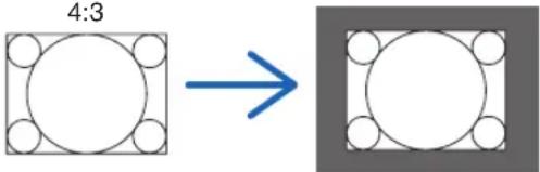 | |
TIP:
- The main resolutions and aspect ratios of the computer are as follows.
| Resolution Aspect Ratio | ||
| VGA 640 × 480 4:3 | ||
| SVGA 800 × 600 4:3 | ||
| XGA 1024 × 768 4:3 | ||
| WXGA 1280 × 768 15:9 | ||
| HD(FWXGA) 1366 × 768 approx. 16:9 | ||
| WXGA 1280 × 800 16:10 | ||
| WXGA+ | 1440 × 900 16:10 | |
| WXGA++ | 1600 × 900 16:9 | |
| SXGA | 1280 × 1024 5:4 | |
| SXGA+ | 1400 × 1050 4:3 | |
| WSXGA+ 1680 × 1050 16:10 | ||
| FHD (1080P) | 1920 × 1080 | 16:9 |
| UXGA | 1600 × 1200 4:3 | |
| WUXGA | 1920 × 1200 | 16:10 |
| WQXGA | 2560 × 1600 | 16:10 |
4-3-5. OVERSCAN
Set overscan (process to cut the frame around the screen).
| OFF Overscan will not be performed. |
| CROP Projects the image with the surroundings hidden. |
| ZOOM Enlarges the image to fit the projection screen. |

4-3-6. IMAGE OPTIONS
When projecting an analog video signal, adjust the screen color shift, flicker and position of the screen.
| H TOTAL Adjust the screen brightness until it is constant (light and dark vertical bands do not appear). (Clock frequency) |
| H START Moves the screen in the horizontal direction. (HORIZONTAL) |
| H PHASE Adjusts the phase so that the screen color shift and flicker are minimized. (Phase) |
| V START Moves the screen in the vertical direction. (VERTICAL) |
NOTE:
- The screen may be distorted while adjusting the clock frequency and phase but this is not a malfunction.
4-3-7. TEST PATTERN
Project a test pattern.
- Press the ◀/▶ button to change the pattern of the test pattern.
- Press the EXIT button to erase the test pattern.
- You can also display the test pattern by pressing the TEST button on the remote control.
The test pattern is displayed when checking the screen distortion during installation or when adjusting the focus. We recommend that you adjust the focus 30 minutes or more after the test pattern is projected.
4-3-8. 3D
Set this to projecting 3Dimages with the projector.
| FORMAT Select the 3D video | format (recording/transmission method).Select the format according to the 3D broadcast and 3D media.Normally select [AUTO]. If the 3D detection signal of the format cannot be determined, select the format of the 3D input signal. | |
| EYE SWAP Reverses the disp | ay order of the left and right images. | |
| DLP® Link Turn this to [ON] to | project 3D images in the DLP® Link format. | |
| DARK TIME Set according to the 3D glasses used. | ||
| SYNC DELAY Adjust this when the 3D synchronization signal cannot be received well by the 3D glasses. | ||
| SYNC REFERENCE EXTERN | AL Displayed when the 3D synchronization signal is superimposed on the video signal. | |
| INTERNAL Displayed when the 3D synchronization signal is being input into the 3D SYNC IN terminal of the projector. | ||

CAUTION
Health warning
Health precautions may be described in the 3D video software (Blu-ray player, game, computer video file, etc.) and instruction manual attached to the 3D glasses, so be sure to check these before watching.
To avoid adverse health effects, please note the following:
- Do not use 3D glasses for any purpose other than viewing 3D images.
- View at a distance of at least 2 m away from the screen. Viewing at a close distance to the screen increases eye fatigue.
- Do not view continuously for a long period of time. After viewing for 1 hour, take a rest for 15 minutes or more.
- Consult your doctor before viewing if you or your family members have had light-sensitive seizures before.
- If you experience any abnormalities in your body (such as nausea, dizziness, irritation, headache, eye pain, blurred vision, cramping of limbs, numbness, etc.) while watching, stop watching immediately and take a rest. If the problem persists after a while, consult your doctor.
• View 3D images from the front of the screen. Viewing 3D images from an angle may cause fatigue or eye strain.
NOTE:
- When using a 3D emitter, connect the BNC terminal of the 3D emitter to the 3D SYNC of the projector.
- The 3D glasses receive the synchronization signal output from the 3D emitter, allowing you to view the image in three dimensions. 3D glasses in the DLP® Link format receive the synchronization signal included in the 3D video signal that is reflected on the screen, allowing you to view the video in three dimensions.
Therefore, depending on the surrounding brightness, screen size, viewing distance, etc., it may be difficult to view the 3D image. - Check the operating conditions described in the instruction manual of the Blu-ray player.
- When playing 3D video software on a computer, it may be difficult to view the 3D video if the computer CPU or graphics chip performance is low. Check the computer operating conditions described in the instruction manual attached to the 3D video software.
- Depending on the 3D input signal, the projector may not automatically switch to 3D video.
4-3-9. AUTO ADJUST
When executed, the projected screen is automatically adjusted.
- Automatic adjustment can also be performed by pressing the AUTO ADJUST button on the projector.
NOTE:
- If the screen is distorted even after performing automatic adjustment, adjust the image with [IMAGE OPTIONS].
4-4. PICTURE
4-4-1. PRESET
Select the optimal settings for the projected picture.
| HIGH-BRIGHT Use this setting | when projecting in a bright room. |
| PRESENTATION Use this setting | when making a presentation with PowerPoint etc. |
| VIDEO Use this setting when | projecting TV programs or general video sources. |
4-4-2. CONTRAST/BRIGHTNESS/SHARPNESS/COLOR/HUE
Adjust the image projected on the screen.
| CONTRAST Makes the difference between the dark and bright areas of the image clearer or lighter. | |
| BRIGHTNESS Makes the image brighter or darker. | |
| SHARPNESS Makes the picture sharp and soft. | |
| COLOR Makes the color darker or lighter. | |
| HUE Makes the image appear reddish or greenish. |
4-4-3. COLOR TEMPERATURE
Adjust the balance of the colors (R, G, B) to optimize the color reproducibility.
A color temperature with a high numerical value becomes bluish white while one with a low numerical value becomes reddish white. The setting can be selected from 5400K, 6500K, 7500K, 9300K and NATIVE.
4-4-4. COLOR GAMUT
You can change the projector's color gamut according to the projected image.
4-4-5. GAMMA CORRECTION
Select the gradation of the picture. With this, even dark areas can be reproduced vividly.
- The [DICOM SIM.] setting on the projector is used to adjust the image to an image that approximates the DICOM standard and thus the image may not be projected correctly. For this reason, use the [DICOM SIM.] setting only for educational purposes and not for actual diagnosis.
- The DICOM in [DICOM SIM.] is the name of the global standard used for storing and communicating medical images. It is used in computer tomography (CT), magnetic resonance imaging (MRI), endoscopes and other medical diagnosis.
4-4-6. WHITE BALANCE
Adjust the white level and black level of the signal to achieve the best color reproduction.
| CONTRAST R Adjusts the white color of the picture. | |
| CONTRAST G | |
| CONTRAST B | |
| BRIGHTNESS R Adjusts the black color of the picture. | |
| BRIGHTNESS G | |
| BRIGHTNESS B | |
NOTE:
- When the white balance is adjusted, the color temperature value differs from the actual color tone.
4-4-7. COLOR CORRECTION
Adjust the tone of the red, green, blue, yellow, magenta (purple) and cyan (bright bluish green) colors.
| RED HUE Adjusts the color near the area centered around red. | |
| SATURATION Adjusts | the intensity of the red color.Move in the “+” direction to make the color more vivid and move in the “-” direction to make the color appear more magenta. |
| GAIN Adjusts the brightness of the red color.Move in the “+” direction to make the color look brighter and move in the “-” direction to make it look darker (black). | |
| GREEN HUE Adjusts the color near the area centered around green.Move in the “+” direction to make the color appear more cyan and move in the “-” direction to make the color appear more yellow. | |
| SATURATION Adjusts | the intensity of the green color.Move in the “+” direction to make the color more vivid and move in the “-” direction to make the color less vivid (white). |
| GAIN Adjusts the brightness of the green color.Move in the “+” direction to make the color look brighter and move in the “-” direction to make it look darker (black). | |
| BLUE HUE Adjusts the color near the area centered around blue.Move in the “+” direction to make the color appear more magenta and move in the “-” direction to make the color appear more cyan. | |
| SATURATION Adjusts | the intensity of the blue color.Move in the “+” direction to make the color more vivid and move in the “-” direction to make the color less vivid (white). |
| GAIN Adjusts the brightness of the blue color.Move in the “+” direction to make the color look brighter and move in the “-” direction to make it look darker (black). | |
| CYAN HUE Adjusts the color near the area centered around cyan.Move in the “+” direction to make the color appear more blue and move in the “-” direction to make the color more green. | |
| SATURATION Adjusts | the intensity of the cyan color.Move in the “+” direction to make the color more vivid and move in the “-” direction to make the color less vivid (white). |
| GAIN Adjusts the brightness of cyan.Move in the “+” direction to make the color look brighter and move in the “-” direction to make it look darker (black). | |
| MAGENTA HUE Adjusts | the color near the area | centered around magenta.Move in the “+” direction to make the color appear more red and move in the “-” direction to make the color more blue. |
| SATURATION Adjusts | the intensity of the magenta color.Move in the “+” direction to make the color more vivid and move in the “-” direction to make the color less vivid (white). | |
| GAIN Adjusts the brightness of magenta.Move in the “+” direction to make the color look brighter and move in the “-” direction to make it look darker (black). | ||
| YELLOW HUE Adjusts | the color near the area | centered around yellow.Move in the “+” direction to shift the color closer to green and move in the “-” direction to shift the color closer to red. |
| SATURATION Adjusts | the intensity of the yellow color.Move in the “+” direction to make the color more vivid and move in the “-” direction to make the color less vivid (white). | |
| GAIN Adjusts the brightness of yellow.Move in the “+” direction to make the color look brighter and move in the “-” direction to make it look darker (black). | ||
| WHITE RED GAIN Adjusts | the white color. | Move in the “+” direction to shift the color closer to red and move in the “-” direction to shift the color closer to cyan. |
| GREEN GAIN Adjusts | the white color.Move in the “+” direction to shift the color closer to green and move in the “-” direction to shift the color closer to magenta. | |
| BLUE GAIN Adjusts the white color.Move in the “+” direction to shift the color closer to blue and move in the “-” direction to shift the color closer to yellow. | ||
| RESET Returns all adjustment values for color correction to the factory settings. | ||
4-4-8. NOISE REDUCTION
When projecting a video image, the noise reduction function can be used to reduce screen noise (roughness and disturbance). You can choose the noise reduction effect from 4 levels [0] [1] [2] [3] according to the noise level.
4-4-9. DYNAMIC CONTRAST
If [ON] is selected, the most optimal contrast ratio is used according to the picture.
When [DYNAMIC CONTRAST] is set to [ON], the laser emission stops when the time set in [LIGHT OFF TIMER] elapses upon the entire projected screen turning black.
If [LIGHT OFF TIMER] is set to [OFF], laser emission will not stop even when the screen turns black.
4-5. DISPLAY
4-5-1. LENS LOCK
Disables the use of the ZOOM/FOCUS adjustment, lens shift and [CENTER LENS] functions.
By performing [LENS LOCK], it is possible to prevent other people from adjusting the lens without permission after the lens has been adjusted.
4-5-2. LENS CONTROL
Adjusts the ZOOM/FOCUS and shifts the lens.
- [LENS CONTROL] can also be performed by pressing the button on the projector or remote control.
Follow the procedure below to operate.
- Move the cursor to [LENS CONTROL] in the menu, then press the ENTER or ▶ button.
The test pattern and ZOOM/FOCUS adjustment screen will be displayed.
-
To adjust the focus, press the ◀/▶ button.
-
To adjust the zoom, press the ▼/▲ button.
-
When you have finished adjusting the focus and zoom, press the ENTER button.
The lens shift adjustment screen will be displayed.
- Press the ▼▲◀▶ button.
The lens shifts in the direction of the pressed button.
- When the lens shift is complete, press the ENTER button.
The selected image will be projected and the ZOOM/FOCUS adjustment screen will be displayed.
Repeat Step 2 to 6 above.
- To exit [LENS CONTROL], press the MENU button.
4-5-3. LENS MEMORY
Stores the projection position (lens shift) on the screen in the projector's memory. A maximum of 10 values can be stored. When the stored adjustment value is recalled, the lens shift is automatically adjusted.
4-5-4. CENTER LENS
Returns the lens to its home position.
This function is used to calibrate the lens shift adjustment range.
After replacing the lens unit, be sure to execute [CENTER LENS]. (→ page 16)
4-5-5. DIGITAL ZOOM
Enlarge the screen up to a maximum of 2 times.
- Digital zoom can also be performed by holding the CTL button and pressing the VOL/D-ZOOM + button on the remote control.
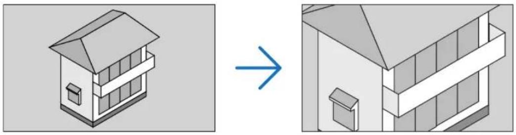
natural_image
Isometric view of a two-story building with a chimney, shown before and after transformation (no text or symbols)| DIGITAL ZOOM Enlarges the screen by up to 2 times. | |
| DIGITAL PAN | When the screen is enlarged with digital zoom, press the ◀/► button to move the screen in the horizontal direction. |
| DIGITAL SCAN | When the screen is enlarged with digital zoom, press the ◀/► button to move the screen in the vertical direction. |
| RESET Returns the screen to its original state. | |
4-5-6. GEOMETRIC CORRECTION
Corrects the distortion of the projection screen when projecting from an oblique direction to the screen to fit the image to the screen frame.
KEYSTONE
Adjusts the keystone distortion by combining the horizontal adjustment and vertical adjustment of the projection screen.
| HORIZONTAL | -600 (-60°) 0 600 (60°) | ||
 |  | 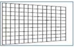 | |
| VERTICAL | -400 (-40°) 0 400 (40°) | ||
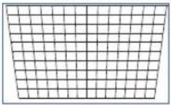 |  |  | |
| ROTATION Allows the image to be rotated after adjusting the horizontal and vertical keystone distortion. | |||
| RESET Returns the keystone adjustment value to the factory setting. | |||
ROTATION
Rotates the screen within the display area.
As the angle of rotation increases, the screen becomes smaller.
| ROTATION | -100 (-25°) 0 100 (25°) | ||
 |  |  | |
| RESET Returns the rotation adjustment value to the factory setting. | |||
PINCUSHION / BARREL
Adjust this when projecting onto a cylindrical screen or spherical surface.
| H PINCUSHION / BARREL | -150 (-30%) 0 300 (60%) | ||
 |  |  | |
| V PINCUSHION / BARREL | -150 (-30%) 0 300 (60%) | ||
 |  |  | |
| H KEYSTONE Example of keystone adjustment in the horizontal direction: | |||
| V KEYSTONE Example keystone adjustment in the vertical direction: | |||
| ROTATION Rotation example: |  | ||
| RESET Returns the adjustment value of [PINCUSHION / BARREL] to the factory setting. | |||
NOTE:
- [H KEYSTONE] or [V KEYSTONE] can be used when adjusting [H PINCUSHION / BARREL] or [V PINCUSHION / BARREL].
- [ROTATION] can be used when adjusting [H KEYSTONE] or [V KEYSTONE].
- Since the screen rotates within the display area, the screen becomes smaller as the rotation angle increases.
ARC
Adjusts the barrel-shaped distortion for each of the 4 sides.
| TOP | -150 (-30%) 0 150 (30%) | ||
 |  | 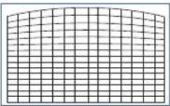 | |
| BOTTOM | -150 (-30%) 0 150 (30%) | ||
 |  |  | |
| LEFT | -150 (-30%) 0 150 (30%) | ||
 |  |  | |
| RIGHT | -150 (-30%) 0 150 (30%) | ||
 |  |  | |
| RESET Resets the [ARC] adjustment value to the factory setting. | |||
TOP LEFT CORNER
Adjusts the top left corner distortion.
| HORIZONTAL | -192 (Pixels) 0 192 (Pixels) | ||
 |  |  | |
| VERTICAL | -120 (Pixels) 0 120 (Pixels) | ||
 |  |  | |
| RESET Returns the adjustment value to the factory setting. | |||
TOP RIGHT CORNER
Adjusts the top right corner distortion.
| HORIZONTAL | -192 (Pixels) 0 192 (Pixels) | ||
 |  |  | |
| VERTICAL | -120 (Pixels) 0 120 (Pixels) | ||
 |  |  | |
| RESET Returns the adjustment value to the factory setting. | |||
BOTTOM LEFT CORNER
Adjusts the bottom left corner distortion.
| HORIZONTAL | -192 (Pixels) 0 192 (Pixels) | ||
 |  |  | |
| VERTICAL | -120 (Pixels) 0 120 (Pixels) | ||
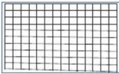 | 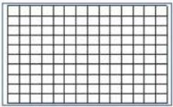 | 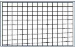 | |
| RESET Returns the adjustment value to the factory setting. | |||
BOTTOM RIGHT CORNER
Adjusts the bottom right corner distortion.
| HORIZONTAL | -192 (Pixels) 0 192 (Pixels) | ||
 |  |  | |
| VERTICAL | -120 (Pixels) 0 120 (Pixels) | ||
 |  |  | |
| RESET Returns the adjustment value to the factory setting. | |||
PC TOOL
Recall the geometric correction data that is registered in the projector beforehand.
Three types of correction data can be registered.
4-5-7. BLANKING
Adjusts the display range (BLANKING) of the top, bottom, left, and right edges of the video signal.
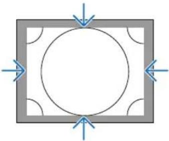
natural_image
Pure geometric diagram with a circle inside a square frame and directional arrows, no text or symbols present.4-5-8. EDGE BLENDING
Adjust the edges (boundaries) of the projection screen when projecting high-resolution images by combining multiple projectors on the left, right, top and bottom.
| MODE Enables/disables the edge blending function. | |
| MARKER Set whether to display the markers when adjusting the range and display position.When this is turned on, when the white level is increased from [0], a green marker is displayed for range adjustment and a red marker is displayed for display position adjustment. | |
| RANGE Adjusts the edge blending range (width). | |
| BLACK LEVEL Adjusts the black level of non-overlapping images on the multiple screens. | |
| RESET Returns the edge blending adjustment value to the factory setting. |
Example of a screen that is projected by arranging the images of 4 projectors with 2 units each vertically and horizontally.

4-5-9. SCREEN TYPE
Set the ratio of the screen to project.
Select from 16:10, 16:9 or 4:3.
4-6. SETUP
4-6-1. LANGUAGE
Select the language to be displayed in the menu.
NOTE:
- [LANGUAGE] will not be changed even if [RESET ALL] is performed.
4-6-2. ORIENTATION
Select the orientation according to the installation status of the projector and screen.

WARNING
- Consult your dealer regarding the installation. Never install the projector on your own. The projector may drop and cause injury.
• Install in such a way that viewers do not enter the Restriction Zone (HD).
| DESKTOP FRONT Install on a table and project from the front of the screen | |
 | |
| CEILING REAR Install on the ceiling and project from the back of the screen | |
 | |
| DESKTOP REAR Install on a table and project from the back of the screen | |
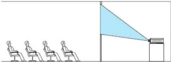 | |
| CEILING FRONT Install on the ceiling and project from the front of the screen | |
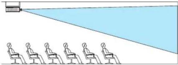 | |
NOTE:
- [ORIENTATION] will not be changed even if [RESET ALL] is performed.
4-6-3. FAN MODE
Set the cooling fan operation to lower the temperature inside the projector.
| AUTO Turns the fan at an appropriate speed using the temperature sensor and pressure sensor inside the projector. The fan rotation is quiet. |
| HIGH ALTITUDE Select this option when using the projector in a low pressure area e.g. at a high altitude of about 1600 m or more above sea level. The fan will constantly rotate at a high speed. |
NOTE:
- Be sure to set it to [HIGH ALTITUDE] when using the projector for several consecutive days.
• [FAN MODE] will not be changed even if [RESET ALL] is performed. - If you are using the projector at an altitude of about 1600 m or more above sea level, be sure to set the [FAN MODE] to [HIGH ALTITUDE]. If you do not set it to [HIGH ALTITUDE], the interior of the projector will get hot, resulting in a malfunction.
- If the projector is used at an altitude of about 1600 m or more above sea level without setting [FAN MODE] to [HIGH ALTITUDE], the temperature protector may be activated and the power may be turned off automatically.
Furthermore, since the internal temperature rises after the light source turns off, the temperature protector may be activated and the power may not turn on. In this case, wait for a while before turning on the power.
- When used at a high altitude, replacement of optical components (such as the light source etc.) may be accelerated.
4-6-4. AUTO POWER OFF
If there is no signal input or no operation has been carried out for a certain period of time, the power of the projector will automatically turn off.
4-6-5. DIRECT POWER ON
Set the projector to turn on automatically when AC power is supplied to it.
Use this when you want to control the projector with a control console etc.
| OFF When AC power is supplied, the projector goes into the standby mode. | |
| ON Projects the signal | from the input terminal that was projected when the power was last turned off.TIP:When [AUTO SOURCE] is turned to [ON] and [DIRECT POWER ON] turns [ON], [AUTO SOURCE] is activated. |

WARNING
- The projector produces intense light. When turning on the power, make sure no one within the projection range is looking at the lens.
4-6-6. NETWORK SETTINGS
Configure the network settings of the projector.
NOTE:
• [NETWORK SETTINGS] will not be changed even if [RESET ALL] is performed.
| NETWORK MODE Always select [LAN1]. [LAN2] is used for servicing. | ||
| STANDBY POWER When [ON] is selected, you can exercise control via a wired LAN even when the projector is in standby mode.However, the power consumption in the standby mode is higher compared to the [OFF] mode. | ||
| DHCP | ON The DHCP server | automatically assigns an IP address, subnet mask and gateway. |
| OFF Manually set an arbitrary IP address or subnet mask assigned by the network administrator. | ||
| IP ADDRESS When [DHCP] is set to [OFF], this sets the IP address of the projector in the network which it is connected to.Use the following procedure to change the IP address.Move the cursor to the IP address and press the button. Mode changes to the edit mode.Press the ▶/▲ button to select a number.Press the ▼/▲ button to increase or decrease the number.Press the ENTER button to confirm. | ||
| SUBNET MASK When [DHCP] is set to [OFF], this sets the subnet mask of the projector in the network which it is connected to. | ||
| GATEWAY When [DHCP] is set to [OFF], this sets the default gateway of the network the projector is connected to.Refer to the [IP ADDRESS] item for details on how to change the gateway. | ||
| DNS Set the IP address of the DNS server of the network the projector is connected to.Refer to the [IP ADDRESS] item for details on how to change the DNS. | ||
| AMX BEACON If you connect the projector to a network compatible with the NetLinx control system of AMX Corporation, you can enable/disable the detection setting from AMX Device Discovery.ON Enables the detection of the projector from AMX Device Discovery.OFF Disables the detection of the projector from AMX Device Discovery.TIP:• AMX Device Discovery is a function to automatically detect a compatible device when it is connected and download the Device Discovery Module required for control from the AMX server. | ||
| MAC ADDRESS Displays the MAC address of the projector. | ||
| PROJECTOR NAME Displays the name of the projector. Use the HTTP server function to change the name of the projector. (→ page 35) | ||
| HOST NAME Displays the host name of the projector.Use the HTTP server function to change the host name of the projector. (→ page 35) | ||
NOTE:
- When setting the geometric correction by ProAssist, be sure to set [NETWORK MODE] to [LAN2].
- Be sure to set [IP ADDRESS] not to conflict to other products on the same network.
• After set the geometric correction by ProAssist, be sure to set [NETWORK MODE] to [LAN1].
4-6-7. LIGHT MODE
Adjust the light source output of the projector.
| NORMAL Brightness changes to 100% and the screen becomes bright. | |
| ECO The brightness becomes about 80% of the brightness in the [NORMAL] mode.The operating noise and power consumption will also decrease due to control of the cooling fan according to the brightness. |
TIP:
- You can check the light hours used from [INFO.] [LIGHT HOURS USED] in the on-screen menu. ( page 70)
- If there is no input signal (blue, black or logo display) for about 30 seconds, the mode automatically switches to [ECO]. After this, when the projector detects an input signal, the [ECO] mode returns to the previously set mode.
- The projector is equipped with a function to detect the pressure and temperature and control the output.
When used in a location where the altitude or temperature is high, the brightness decreases regardless of the [LIGHT MODE] setting. This mode is called the “Forced ECO MODE”.
When “Forced ECO MODE” is selected, the screen becomes slightly darker, and the LIGHT indicator and TEMP. indicator lights up in orange.
| Altitude \ Temperature 5°C – 25°C 26°C – 30°C 31°C – 35°C 36°C – 40°C | ||
| 2,438 m – 4,200 m 100% 90% 80% 70% | ||
| 1,219 m – 2,438 m 100% 100% 90% 80% | ||
| 0 m – 1,219 m 100% 100% 100% 80% |
4-6-8. LIGHT ADJUST (LIGHT MODE)
When the mode is set to [NORMAL] in [LIGHT MODE], the brightness can be adjusted within a range of 30% to 100% (in 1% increments).
NOTE:
- When using the NP49ZL lens unit, brightness can be adjusted within a range of 30% to 87%.
4-6-9. CONSTANT BRIGHTNESS (LIGHT MODE)
Controls the brightness so that it is kept constant based on the brightness in effect at the time [ON] is selected. The adjustment value will be saved until [CONSTANT BRIGHTNESS] is set to [OFF] even if the power is turned off.
- To re-adjust the brightness, turn this setting [OFF] once before making further adjustments.
NOTE:
- [CONSTANT BRIGHTNESS] is a function to keep the brightness constant. The color will not be fixed.
TIP:
- When projecting multiple projectors in combination, we recommend that you adjust the brightness setting so that the brightness is reduced slightly and then set [CONSTANT BRIGHTNESS] to [ON].
4-6-10. BACKGROUND
Select the background color when there is no input signal.
You can select either blue, black, or the NEC logo.
NOTE:
- [BACKGROUND] will not be changed even if [RESET ALL] is performed.
4-6-11. STARTUP LOGO
Select whether or not to display the NEC logo on the screen during startup.
NOTE:
- [STARTUP LOGO] will not be changed even if [RESET ALL] is performed.
4-6-12. REMOTE CONTROL
Configure the remote sensor setting and control ID.
- [REMOTE SENSOR] is used to set the remote control sensor at the front and rear of the main projector.
- When [CONTROL ID] is used, IDs can be assigned to multiple projectors, and each projector can be operated individually by switching the ID using a single remote control. It is also used when setting the same ID to multiple projectors and performing batch operations with a single remote control.
| REMOTE SENSOR | |
| ALL Enables the front and rear remote control sensors and the remote control signal of the HDBaseT/LAN port. | |
| FRONT/BACK Enables the front and rear remote control sensors. | |
| FRONT Enables only the front remote control sensor. | |
| BACK Enables only the rear remote control sensor. | |
| HDBaseT Select this to set the transmission of the remote control signal on the transmission device side to operate the remote control when connected to a commercially available HDBaseT compatible transmitter. | |
| CONTROL ID Select whether to enable or disable the [CONTROL ID] function. | |
| CONTROL ID NUMBER Select a number from 1 to 99 to assign to the projector. | |
NOTE:
- When [REMOTE SENSOR] is set to [HDBaseT], the remote control sensor on the rear side of the projector is enabled.
- When [CONTROL ID] is set to [ON], the projector cannot be operated from a remote control that does not support the [CONTROL ID] function (except for the projector operation buttons).
- [CONTROL ID] will not be changed even if reset is performed.
TIP:
- The remote control may not work well due to the influence of fluorescent lights, for example when the projector is suspended from the ceiling. In this case, try changing the remote control sensor setting.
How to set/change the ID in the remote control
- Turn on the power of the projector.
- Press the ISD SET button on the remote control.
The [CONTROL ID] screen will be displayed.
CONTROL ID (ACTIVE)
At this point, [ACTIVE] is displayed if the projector can be operated with the current remote control ID, and a [INACTIVE] screen is displayed if it cannot be operated.
If you want to operate a projector that is [INACTIVE], set the same number in the remote control as the control ID of the projector in Step 3.
- Press the numeric buttons while holding down the ID SET button on the remote control to set the remote control ID.
For example, to change the number to [3], press the number 3.
Enter 000 or press the CLEAR button if no ID is going to be set (operate all projectors at once).
TIP:
- Remote control IDs can be registered from 1 to 99.
- Release the ID SET button.
The [CONTROL ID] screen will be displayed.
At this point, the [ACTIVE]/[INACTIVE] screen will be updated with the changed remote control ID.
NOTE:
- If the battery of the remote control is exhausted or removed, the ID may be cleared after a while.
- If any button is pressed with the remote control battery removed, the set ID will be cleared.


4-6-13. TRIGGER-1/2
Set whether to output the control voltage for screen control from the screen trigger terminal according to the input video signal.
4-6-14. MENU
| MENU POSITION Changes the position to display the menu. You can choose from 5 locations. | |
| MENU TRANSLUCENT Select the menu transparency. | |
| DISPLAY TIME Select the time until the menu is automatically closed when the menu is displayed and no button is pressed next. | |
| MESSAGE DISPLAY Select whether or not to display the projector's message at the bottom of the projection screen. | |
| CONTROL PANEL LOCK Disables the operation buttons on the projector. | |
| OFF The buttons on the projector are enabled. | |
| ON The buttons on the projector are disabled (locked). | |
| TIP:The projector can still be operated using the remote control even when the buttons on the projector are locked. | |
4-7. INFO. And RESET ALL
4-7-1. INFO.
| MODEL NO. Displays the model name. |
| SERIAL NUMBER Displays the serial number. |
| FIRMWARE Displays the firmware version number of the main CPU. |
| LANCPU Displays the firmware version number of the network CPU. |
| SUB-CPU Displays the firmware version number of the sub CPU. |
| CONTROL ID Displays the control ID set in the projector. |
| INPUT TERMINAL Displays the name of the input terminal being projected. |
| SIGNAL FORMAT Displays the signal format of the signal being projected. |
| H/V REFRESH RATE Displays the horizontal and vertical frequency of the signal being projected. |
| PIXEL CLOCK Displays the pixel clock of the signal being projected. |
| LIGHT HOURS USED Displays the light hours used. |
| THERMAL STATUS Displays the temperature of the air inlet, the temperature inside the projector, the rpm of the cooling fan, and the rpm of the water cooling pump. |
4-7-2. RESET ALL
All adjustment values and setting values stored in the projector will be reset to the factory settings.
The reset process takes some time to run.
Data that cannot be reset
| DISPLAY LENS CONT | ROL |
| CENTER LENS | |
| SETUP LANGUAGE | |
| ORIENTATION | |
| FAN MODE | |
| NETWORK SETTINGS | |
| BACKGROUND | |
| STARTUP LOGO |
5. Installation and Connections
5-1. Connecting to Other Equipment
Below is an example of connections to external equipment.
No connection cables are included with this projector. Use the appropriate cables for the connections.

CAUTION
- Be sure to turn off the projector before connecting the projector to an external device. In doing so, do not enter the radiation zone (HD). If projected light enters your eyes, it may cause visual impairment.
NOTE:
- For HDMI, DisplayPort, BNC, and RS232C, please use a shielded cable.
For 15-pin mini D-Sub and DVI-D, please use a shielded signal cable with ferrite core.
Use of other cables may cause interference with radio and television reception.

flowchart
graph TD
    A["Computer, etc. Blu-ray player, etc."] --> B["Blu-ray player"]
    B --> C["Professional video equipment, etc."]
    C --> D["Laptop"]
    D --> E["Professional video equipment, etc."]
    E --> F["Computer, etc."]
    G["HDBaseT transmission device, etc."] --> H["Blu-ray player"]
    H --> I["Professional video equipment, etc."]
    I --> J["Laptop"]
    K["4"] --> L["Switch"]
    L --> M["Switch"]
    M --> N["Switch"]
    N --> O["Switch"]
    O --> P["Switch"]
    P --> Q["Switch"]
    Q --> R["Switch"]
    R --> S["Switch"]
    S --> T["Switch"]
    T --> U["Switch"]
    U --> V["Switch"]
    V --> W["Switch"]
    W --> X["Switch"]
    X --> Y["Switch"]
    Y --> Z["Switch"]
    Z --> AA["Switch"]
    AA --> AB["Switch"]
    AB --> AC["Switch"]
    AC --> AD["Switch"]
    AD --> AE["Switch"]
    AE --> AF["Switch"]
    AF --> AG["Switch"]
    AG --> AH["Switch"]
    AH --> AI["Switch"]
    AI --> AJ["Switch"]
    AJ --> AK["Switch"]
    AK --> AL["Switch"]
    AL --> AM["Switch"]
    AM --> AN["Switch"]
    AN --> AO["Switch"]
    AO --> AP["Switch"]
    AP --> AQ["Switch"]
    AQ --> AR["Switch"]
    AR --> AS["Switch"]
    AS --> AT["Switch"]
    AT --> AU["Switch"]
    AU --> AV["Switch"]
    AV --> AW["Switch"]
    AW --> AX["Switch"]
    AX --> AY["Switch"]
① HDMI cable (not supplied)
- Use a certified High Speed HDMI ^ Cable or High Speed HDMI ^ Cable with Ethernet.
- When connecting the HDMI 1 IN or HDMI 2 IN connector of the projector to the Blu-ray player, the projector's video level can be made settings in accordance with the Blu-ray player's video level. In the menu select [ADJUST] → [VIDEO] → [VIDEO LEVEL] and make necessary settings.
② DisplayPort cable (not supplied)
- Use a certified DisplayPort cable.

③ BNC cable (not supplied)
- Use cables that are 5C-FB or higher (5C-FB, 7C-FB, etc.) or Belden 1694A or higher. In addition, use cables with a cable length 100m or less.
- The length of cables that can be used may differ, depending on the signal.
④ LAN cable (not supplied)
- Please use a shielded twisted pair (STP) cable of Category 5e or higher for the LAN cable (sold commercially).
- The HDBaseT/LAN port of the projector supports HDMI signals (HDCP) from transmission devices, control signals from external devices (serial, LAN) and remote control signals (IR commands).
- The maximum transmission distance over the LAN cable is 100 m.
- Please do not use other transmission equipment between the projector and transmission equipment. The picture quality may be degraded as a result.
- This projector is not guaranteed to work with all HDBaseT transmission devices sold commercially.
⑤ Computer cable (mini D-sub 15 pin) (not supplied)
- Use a signal cable with ferrite core.
- Use a signal cable with ferrite core.
⑥ DVI-D cable (not supplied)
6. Maintenance

WARNING
- Turn off the projector, and unplug the projector before cleaning.
- Please do not use a spray containing flammable gas to remove dust attached to the lens or the cabinet, etc. Doing so may result in fires.
6-1. Cleaning the Lens
- Use a blower or lens paper to clean the lens, and be careful not to scratch or mar the lens.

natural_image
Illustration of a hand inserting a component into a device panel (no text or symbols visible)6-2. Cleaning the Cabinet
- Use a dry soft cloth to wipe dust off the cabinet.
If heavily soiled, use a mild detergent.
- Never use strong detergents or solvents such as alcohol or thinner.
- When cleaning the ventilation slits using a vacuum cleaner, do not force the brush of the vacuum cleaner into the slits of the cabinet.

natural_image
Technical line drawing of a rectangular electronic device with ventilation grilles and coiled tubing (no text or symbols)Vacuum the dust off the ventilation slits.
- Poor ventilation caused by dust accumulation in ventilation openings can result in overheating and malfunction. These areas should be cleaned regularly.
- Do not scratch or hit the cabinet with your fingers or any hard objects.
- Contact your dealer for cleaning the inside of the projector.
NOTE:
- Do not apply volatile agent such as insecticide on the cabinet, the lens, or the screen. Do not leave a rubber or vinyl product in prolonged contact with it. Otherwise the surface finish will be deteriorated or the coating may be stripped off.
7. Appendix
7-1. Throw distance and screen size
This projector can be used with 5 kinds of optional lenses (sold separately). Refer to the information on this page and use a lens suited for the installation environment (screen size and throw distance). Request the dealer to attach or detach the lens unit.
Lens types and throw distance
(Unit: inch)
| Screen size Lens | unit model name | ||||
| NP45ZL NP46 | ZL NP47ZL NP48ZL | NP49ZL | |||
| 50 40 – 51 52 | -66 63 – 86 87 – 16 | 9 170 – 295 | |||
| 70 56 – 70 71 | -94 91 – 118 119 – | 236 237 – 417 | |||
| 100 75 – 102 1 | 03 – 133 126 – 169 | 170 – 338 339 – 594 | |||
| 120 91 – 122 1 | 23 – 157 154 – 204 | 205 – 405 406 – 712 | |||
| 150 115 – 153 | 154 – 196 189 – 255 | 256 – 507 508 – 889 | |||
| 180 138 – 185 | 186 – 236 229 – 307 | 308 – 610 611 – 1066 | |||
| 200 154 – 204 | 205 – 263 256 – 338 | 339 – 677 678 – 1188 | |||
| 250 189 – 255 | 256 – 330 319 – 425 | 426 – 846 847 – | 1484 | ||
| 300 229 – 307 | 308 – 397 382 – 507 | 508 – 1015 1016 – 1779 | |||
(Unit: m)
| Screen size Lens unit model name | ||||||
| (inch) (m) | NP45ZL NP | 46ZL NP47ZL NP48 | ZL NP49ZL | |||
| 50 1.27 | 1.0 - 1.3 1 | 3 - 1.7 1.6 - 2.2 2 | 2 - 4.3 4.3 - 7.5 | |||
| 70 1.78 | 1.4 - 1.8 1 | 8 - 2.4 2.3 - 3.0 3 | 0 - 6.0 6.0 - 10.6 | |||
| 100 | 2.54 1.9 | -2.6 2.6 - 3.4 3.2 | -4.3 4.3 - 8.6 8.6 - 15.1 | |||
| 120 | 3.05 | 2.3 - 3.1 | 3.1 - 4.0 | 3.9 - 5.2 | 5.2 - 10.3 | 10.3 - 18.1 |
| 150 | 3.81 | 2.9 - 3.9 | 3.9 - 5.0 | 4.8 - 6.5 | 6.5 - 12.9 | 12.9 - 22.6 |
| 180 | 4.57 | 3.5 - 4.7 | 4.7 - 6.0 | 5.8 - 7.8 | 7.8 - 15.5 | 15.5 - 27.1 |
| 200 | 5.08 | 3.9 - 5.2 | 5.2 - 6.7 | 6.5 - 8.6 | 8.6 - 17.2 | 17.2 - 30.2 |
| 250 | 6.35 4.8 | -6.5 6.5 | -8.4 8.1 | -10.8 10.8 | -21.5 21.5 | -37.7 |
| 300 | 7.62 | 5.8 - 7.8 | 7.8 - 10.1 | 9.7 - 12.9 | 12.9 - 25.8 | 25.8 - 45.2 |

CAUTION
- The law requires that the lens hood be mounted when using the NP49ZL lens unit in the USA or China. Be sure to ask your dealer to mount the lens hood (model NP01LH).
TIP:
• Calculation of the throw distance from the screen size
NP45ZL lens throw distance (m) = H × 0.9 to H × 1.2 : 40"/1.0 m (min.) to 307"/7.8 m (max.)
NP46ZL lens throw distance (m) = H × 1.2 to H × 1.6 : 52"/1.3 m (min.) to 397"/10.1 m (max.)
NP47ZL lens throw distance (m) = H × 1.5 to H × 2.0 : 63"/1.6 m (min.) to 507"/12.9 m (max.)
NP48ZL lens throw distance (m) = H × 2.0 to H × 4.0 : 87"/2.2 m (min.) to 1015"/25.8 m (max.)
NP49ZL lens throw distance (m) = H × 4.0 to H × 7.0 : 170"/4.3 m (min.) to 1779"/45.2 m (max.)
"H" (Horizontal) refers to the screen width.
* Figures differ by several % with the table above because the calculation is approximate.
Ex.: Throw distance when projecting on a 100" screen using the NP47ZL lens:
According to the "Screen Size (for reference)" table ( page 76), H (screen width) = 84.8'' / 215.4 cm (approx. 2.15m ).
The throw distance is 84.8"/2.15 m × 1.5 to 84.8"/2.15 m × 2.0 = 127"/3.2 m to 170"/4.3 m (because of the zoom lens).
Projection range for the different lenses

Tables of screen sizes and dimensions

| Size Screen width Screen height | ||||||
| (inches) (cm) (inches) (cm) (inches) (cm) | ||||||
| 50 127.0 | 42.4 | 107.7 | 26.5 | 67.3 | ||
| 70 177.8 | 59.4 | 150.8 | 37.1 | 94.2 | ||
| 100 254.0 | 84.8 | 215.4 | 53.0 | 134.6 | ||
| 120 304.8 | 101.8 | 258.5 | 63.6 | 161.5 | ||
| 150 381.0 | 127.2 | 323.1 | 79.5 | 201.9 | ||
| 180 457.2 | 152.6 | 387.7 | 95.4 | 242.3 | ||
| 200 508.0 | 169.6 | 430.8 | 106.0 | 269.2 | ||
| 220 558.8 | 186.6 | 473.9 | 116.6 | 296.2 | ||
| 250 635.0 | 212.0 | 538.5 | 132.5 | 336.5 | ||
| 280 711.2 | 237.4 | 603.1 | 148.4 | 376.9 | ||
| 300 762.0 | 254.4 | 646.2 | 159.0 | 403.9 | ||
| 350 889.0 | 296.8 | 753.9 | 185.5 | 471.2 | ||
| 400 1016.0 | 339.2 | 861.6 | 212.0 | 538.5 | ||
| 450 1143.0 | 381.6 | 969.3 | 238.5 | 605.8 | ||
| 500 1270.0 | 424.0 | 1077.0 | 265.0 | 673.1 | ||
Lens shifting range
This projector is equipped with a lens shift function for adjusting the position of the projected image by using the LENS SHIFT buttons ( page 21). The lens can be shifted within the range shown below.
NOTE:
- Please do not use the lens shift function when projecting portrait images.
Legend: V "Vertical" refers to the screen height and H "Horizontal" refers to the screen width. The lens shift range is expressed as a ratio of height and width, respectively.

*1 NP45ZL only ±45%V
*2 The lens shift range is the same for ceiling installation.
(Example) When using to project on a 150" screen
According to the "Table of screen sizes and dimensions" (→ page 76), H = 130.7"/331.9 cm, V = 73.6"/187.0 cm.
Adjustment range in the vertical direction: the projected image can be moved upwards 0.5 × 73.6"/187.0 cm ≈ 36.8"/93.5 cm*³, downwards approximately 0.5 × 73.6"/187.0 cm ≈ 36.8"/93.5 cm*³ (when the lens is at the center position).
Adjustment range in the horizontal direction: the projected image can be moved to the left 0.15 × 130.7''/331.9 cm ≈ 19.6"/49.8 cm, to the right approximately 0.15 × 130.7''/331.9 cm ≈ 19.6"/49.8 cm.
*3 NP45ZL only 33.1"/84.2 cm.
*4 Figures differ by several % because the calculation is approximate.
7-2. Compatible Input Signal List
Analog RGB
| Signal Resolution ( dots ) Aspect Ratio Refresh Rate ( Hz ) | |||
| VGA 640 × 480 4 : 3 60/75/85/iMac | |||
| SVGA 800 × 600 4 : 3 60/75/85 | |||
| XGA 1024 × 768 4 : 3 60/70/75/85/iMac | |||
| XGA+ 1152 × 864 4 : 3 75 | |||
| WXGA | 1280 × 768 15 : 9 60 | ||
| 1280 × 800 16 : 10 60 | |||
| 1366 × 768 16 : 9 60 | |||
| Quad-VGA 1280 × 960 4 : 3 60/85 | |||
| SXGA 1280 × 1024 5 : 4 60/75/85 | |||
| SXGA+ 1400 × 1050 4 : 3 60/75 | |||
| WXGA+ 1440 × 900 16 : 10 60 | |||
| WXGA++ | 1600 × 900 16 : 9 60 | ||
| UXGA | 1600 × 1200 4 : 3 60 | ||
| WSXGA+ | 1680 × 1050 | 16 : 10 60 | |
| WUXGA | 1920 × 1200 * 1 | 16 : 10 60 (Reduced Blanking) | |
| Full HD 1920 × 1080 | 16 : 9 60 | ||
| MAC 13" | 640 × 480 4 : 3 67 | ||
| MAC 16" | 832 × 624 4 : 3 75 | ||
| MAC 19" | 1024 × 768 4 : 3 75 | ||
| MAC 21" | 1152 × 870 4 : 3 75 | ||
HDMI/HDBaseT
| Signal Resolution ( dots ) Aspect Ratio Refresh Rate ( Hz ) | |||
| VGA 640 × 480 4 : 3 60 | |||
| SVGA 800 × 600 4 : 3 60 | |||
| XGA 1024 × 768 4 : 3 60 | |||
| HD | 1280 × 720 16 : 9 60 | ||
| WXGA | 1280 × 768 15 : 9 60 | ||
| 1280 × 800 16 : 10 60 | |||
| 1366 × 768 16 : 9 60 | |||
| Quad-VGA 1280 × 960 4 : 3 60 | |||
| SXGA 1280 × 1024 5 : 4 60 | |||
| SXGA+ 1400 × 1050 4 : 3 60 | |||
| WXGA+ 1440 × 900 16 : 10 60 | |||
| WXGA++ | 1600 × 900 16 : 9 60 | ||
| WSXGA+ | 1680 × 1050 | 16 : 10 60 | |
| UXGA | 1600 × 1200 4 : 3 60 | ||
| Full HD 1920 × 1080 | 16 : 9 60 | ||
| WUXGA | 1920 × 1200 * 1 | 16 : 10 60 (Reduced Blanking) | |
| HDTV(1080p) | 1920 × 1080 | 16 : 9 24/25/30/50/60 | |
| HDTV(1080i) | 1920 × 1080 | 16 : 9 50/60 | |
| HDTV (720p) | 1280 × 720 16 : 9 50/60 | ||
| SDTV (480i/p) | 720/1440 × 480 | 4:3 / 16:9 | 60 |
| SDTV (576i/p) | 720/1440 × 576 | 4:3 / 16:9 | 50 |
DisplayPort
| Signal Resolution ( dots ) Aspect Ratio Refresh Rate ( Hz ) | |||
| VGA 640 × 480 4 : 3 60 | |||
| SVGA 800 × 600 4 : 3 60 | |||
| XGA 1024 × 768 4 : 3 60 | |||
| HD | 1280 × 720 16 : 9 60 | ||
| WXGA | 1280 × 768 15 : 9 60 | ||
| 1280 × 800 16 : 10 60 | |||
| 1366 × 768 16 : 9 60 | |||
| Quad-VGA 1280 × 960 4 : 3 60 | |||
| SXGA 1280 × 1024 5 : 4 60 | |||
| SXGA+ 1400 × 1050 4 : 3 60 | |||
| WXGA+ 1440 × 900 16 : 10 60 | |||
| WXGA++ | 1600 × 900 16 : 9 60 | ||
| WSXGA+ | 1680 × 1050 | 16 : 10 60 | |
| UXGA | 1600 × 1200 4 : 3 60 | ||
| Full HD 1920 × 1080 | 16 : 9 60 | ||
| WUXGA | 1920 × 1200 * 1 | 16 : 10 60 (Reduced Blanking) | |
| WQXGA | 2560 × 1600 | 16 : 10 60 (Reduced Blanking) | |
| HDTV(1080p) | 1920 × 1080 | 16 : 9 50/60 | |
| HDTV (720p) | 1280 × 720 16 : 9 50/60 | ||
| SDTV (480i/p) | 720/1440 × 480 | 4:3 / 16:9 | 60 |
| SDTV (576i/p) | 720/1440 × 576 | 4:3 / 16:9 | 50 |
BNC
| Signal Resolution ( dots ) Aspect Ratio Refresh Rate ( Hz ) | ||
| HDTV (1080p) 1920 × 1080 16 : 9 50/60 | ||
| HDTV (1080i) 1920 × 1080 16 : 9 50/60 | ||
| HDTV (720p) 1280 × 720 16 : 9 50/60 | ||
| SDTV (480i/p) 720 × 480 4:3 / 16:9 60 | ||
| SDTV (576i/p) 720 × 576 4:3 / 16:9 50 | ||
SDI
| Signal Resolution ( dots ) Aspect Ratio Refresh Rate ( Hz ) | ||
| SD-SDI (480i) 720 × 480 4:3 / 16:9 60 | ||
| SD-SDI (576i) 720 × 576 4:3 / 16:9 50 | ||
| HD-SDI (1035i) 1920 × 1035 16 : 9 60 | ||
| HD-SDI (1080i) 1920 × 1080 16 : 9 50/60 | ||
| HD-SDI (1080p) | 1920 × 1080 16 : 9 24pSF | |
| HD-SDI (1080p) | 1920 × 1080 16 : 9 24/25/30 | |
| HD-SDI (720p) | 1280 × 720 16 : 9 50/60 | |
| 3G-SDI (1080p) | 1920 × 1080 16 : 9 50/60 | |
DVI-D
| Signal Resolution ( dots ) Aspect Ratio Refresh Rate ( Hz ) | |||
| VGA | 640 × 480 | 4 : 3 60 | |
| SVGA | 800 × 600 | 4 : 3 60 | |
| XGA | 1024 × 768 | 4 : 3 60 | |
| HD | 1280 × 720 16 : 9 60 | ||
| WXGA | 1280 × 768 15 : 9 60 | ||
| 1280 × 800 16 : 10 | 60 | ||
| 1366 × 768 16 : 9 60 | |||
| Quad-VGA | 1280 × 960 | 4 : 3 60 | |
| SXGA | 1280 × 1024 5 : 4 60 | ||
| SXGA+ | 1400 × 1050 4 : 3 60 | ||
| WXGA+ | 1440 × 900 16 : 10 | 60 | |
| WXGA++ | 1600 × 900 16 : 9 60 | ||
| WSXGA+ | 1680 × 1050 16 : 10 | 60 | |
| UXGA | 1600 × 1200 4 : 3 60 | ||
| Full HD | 1920 × 1080 16 : 9 60 | ||
| WUXGA | 1920 × 1200 * 1 | 16 : 10 | 60 (Reduced Blanking) |
HDMI 3D
| Signal Resolution ( dots ) | Aspect Ratio | Refresh Rate ( Hz ) | 3D Format |
| 1920 × 1080p | 16 : 9 | 23.98/24 | Frame Packing |
| 50 | Side by Side (Half) | ||
| Top and Bottom | |||
| Frame Sequencial | |||
| 59.94/60 | Side by Side (Half) | ||
| Top and Bottom | |||
| Frame Sequencial | |||
| 1920 × 1080i | 16 : 9 | 50 | Side by Side (Half) |
| 59.94/60 | Side by Side (Half) | ||
| 1280 × 720p 16 : 9 | 50 | Frame Packing | |
| Top and Bottom | |||
| 59.94/60 | Frame Packing | ||
| Top and Bottom |
DisplayPort 3D
| Signal Resolution ( dots ) | Aspect Ratio | Refresh Rate ( Hz ) | 3D Format |
| 1920 × 1080p | 16 : 9 | 50 | Top and Bottom |
| Side by Side (Half) | |||
| Frame Sequencial | |||
| 59.94/60 | Top and Bottom | ||
| Side by Side (Half) | |||
| Frame Sequencial | |||
| 1280 × 720p 16 : 9 | 50 | Top and Bottom | |
| 59.94/60 | Top and Bottom |
*1 Native resolution
- Signals exceeding the projector's resolution are handled with scaling technology.
- With scaling technology, the size of characters and ruled lines may be uneven and colors may be blurred.
- Upon shipment, the projector is set for signals with standard display resolutions and frequencies, but adjustments may be required depending on the type of computer.
7-3. Specifications
| Model name NP-PX2201UL | |||
| Method Single DLP | ^ chip | ||
| Specifications of main parts | |||
| DMD panel Size 0.96" (24.4 mm) (aspect ratio: 16:10) | |||
| Pixels ^ (*)1 | 2,304,000 (1920 dots × 1200 lines) | ||
| Projection lenses | Please refer to the specifications of option lens (→ page 82) | ||
| Light source Laser Diode | |||
| Optical device Optical isolation by dichroic mirror, combining by dichroic prism | |||
| Light output ^ (*)2 | 20,500 lm ^ (*)3 / 21,500 lm (Center) | ||
| Screen size (throw distance) | Please refer to the “Throw distance and screen size” (→ page 74) | ||
| Color reproducibility 10-bit color processing (approx. 1.07 billion colors) | |||
| Scanning frequency Horizontal Digital: 15 kHz, 24 to 153 kHz, conforming to VESA standards | |||
| Main adjustment functions Power zoom, power focus, power lens shift, input signal switching (HDMI 1/HDMI 2/COMPUTER/BNC/DVI-D/DisplayPort/SDI/HDBaseT), auto image adjustment, picture maginification, power on/standby, on-screen display/selection, etc. | |||
| Max. display resolution (horizontal × vertical) | Analog: 1920 × 1200 (WUXGA)Digital: 2560 × 1600 (WQXGA) (by scaling technology) | ||
| Input signal R, G, B, H, V RGB: 0.7 Vp-p/75 ΩH/V Sync: 4.0 Vp-p/TTLSync on G: 1.0 Vp-p/75 Ω (With Sync) | |||
| Input/output terminals | |||
| HDMI Video input HDMI | ^ Connector type A × 2 Deep Color (color depth): 8-/10-/12-bit compatibleColorimetry: RGB, YCbCr444, YCbCr422, YCbCr420, REC2020, REC709, REC601Supports HDCP ^ (*)4 | ||
| DisplayPort Video input DisplayPort × 1Data rate: 5.4 Gbps/2.7 Gbps/1.62 GbpsNo. lanes: 1 lane/2 lanes/4 lanesDeep Color (color depth): 8-/10-/12-bit compatibleColorimetry: RGB, YCbCr444, YCbCr422, REC709, REC601Supports HDCP ^ (*)4 | |||
| HDBaseT/LAN port | Video input RJ-45 × 1, 10BASE-T/100BASE-TXDeep Color (color depth): 8-/10-/12-bit compatibleColorimetry: RGB, YCbCr444, YCbCr422, YCbCr420, REC709, REC601Supports HDCP ^ (*)4 | ||
| SDI (3D/HD/SD) | Video input | BNC × 1Input signals: SMPTE259M, SMPTE292M, SMPTE424MColorimetry: RGB, YCbCr444, YCbCr422, REC709, REC601 | |
| Video output | BNC × 1 | ||
| COMPUTER | Video input Mini | D-Sub 15 Pin × 1, BNC × 5 | |
| Video output | Mini D-Sub 15 Pin × 1 | ||
| DVI-D | Video input DVI-D × 1 | ||
| 3D SYNC IN | Video input BNC × 1, synchronized signal input for 3D use1920 × 1200 RB 120 Hz, Frame Sequential | ||
| 3D SYNC OUT | Video output | BNC × 1, synchronized signal output for 3D use | |
| TRIGGER 1/2 | Video output | Stereo mini jack × 2 | |
| PC CONTROL terminal D-Sub 9-pin × 1, 9600 bps | |||
| REMOTE terminal | Stereo mini jack × 1 | ||
| Usage environment ^ (*)5 | Operating temperature: 32 to 104°F (0 to 40°C)Operating humidity: 20 to 80% (with no condensation) | ||
| Storage temperature: 14 to 140°F (-10 to 60°C)Storage humidity: 20 to 80% (with no condensation) | |||
| Operating altitude: 0 to 4200 m/13779 feet | |||
| Power supply | 200-240 V AC, 50/60Hz | ||
| Power consumption | LIGHT MODE | NORMAL | 1775 W |
| ECO | 1343 W | ||
| STAND-BY POWER | ON | 4.5 W | |
| OFF | 0.4 W | ||
| Rated input current | 9.4 A, 50/60 Hz | ||
| Power cord specification | 15 A or higher | ||
| External dimensions | 20.9" (width) × 9.8" (height) × 29.3" (depth)/530 (width) × 248 (height) × 745 (depth) mm (not including protruding parts)20.9" (width) × 10.8" (height) × 29.4" (depth)/530 (width) × 274.5 (height) × 748 (depth) mm (including protruding parts) | ||
| Weight 112 lbs/51 kg (not including lens) | |||
*1 Effective pixels are more than 99.99%.
*2 This is the light output value that results from setting the [LIGHT MODE] to [NORMAL] and setting the [PRESET] to [HIGH-BRIGHT] while using the NP47ZL lens (sold separately). The light output value is lower when setting the [LIGHT MODE] to [ECO]. ([ECO]: about 80%). If any other mode is selected as the [PRESET] mode, the light output value may drop slightly.
*3 Compliance with ISO21118-2020
*4 If you are unable to view material via the HDMI input, DisplayPort input and HDBaseT input, this does not necessarily mean the projector is not functioning properly. With the implementation of HDCP technology, there may be cases in which certain content is protected with HDCP and might not be displayed due to the decision/intention of the HDCP community (Digital Content Protection, LLC).
Video: Deep Color, 8/10/12-bit
HDMI: Supports HDCP 1.4
DisplayPort: Supports HDCP 1.4
HDBaseT: Supports HDCP 1.4
*5 Depending on the altitude and temperature, the projector goes into "Forced ECO MODE".
- These specifications and the product's design are subject to change without notice.
For additional information visit:
US: https://www.sharpnecdisplays.us
Europe: https://www.sharpnecdisplays.eu
Global: https://www.sharp-nec-displays.com/global/
For information on our optional accessories, visit our website or see our brochure.
Option lens (sold separately)
| NP45ZL Power zoom and focus | |
| throw ratio 0.9–1.2:1, F2.2–2.53, f = 19.34–25.76 mm | |
| NP46ZL Power zoom and focus | |
| throw ratio 1.2–1.56:1, F2.18–2.66, f = 25.69–33.22 mm | |
| NP47ZL Power zoom and focus | |
| throw ratio 1.5–2.0:1, F2.17–2.65, f = 31.90–42.20 mm | |
| NP48ZL Power zoom and focus | |
| throw ratio 2.0–4.0:1, F2.17–2.64, f = 42.60–84.80 mm | |
| NP49ZL Power zoom and focus | |
| throw ratio 4.0–7.0:1, F2.2–2.57, f = 83.93–146.85 mm |

CAUTION
- The law requires that the lens hood be mounted when using the NP49ZL lens unit in the USA or China. Be sure to ask your dealer to mount the lens hood (model NP01LH).
7-4. Cabinet Dimensions
Unit: mm (inch)

The screws specifications for Ceiling Mount:
Screw type: M6
Screw hole dimension on the projector: M6 with the maximum depth 16 mm (0.63")

CAUTION
Do not attempt to mount the projector on a ceiling yourself.
The projector must be installed by qualified technicians in order to ensure proper operation and reduce the risk of bodily injury.
In addition, the ceiling must be strong enough to support the projector and the installation must be in accordance with any local building codes. Please consult your dealer for more information.
7-5. Pin assignments and signal names of main terminals HDMI 1 IN/HDMI 2 IN Terminal (Type A)
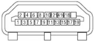
| Pin No. | Signal Pin No. | Signal | ||
| 1 TMDS | Data 2+ 11 TMDS Clock | Shield | ||
| 2 TMDS | Data 2 Shield 12 TMDS Clock- | |||
| 3 TMDS | Data 2- 13 CEC | |||
| 4 TMDS | Data 1+ 14 Disconnection | |||
| 5 TMDS | Data 1 Shield 15 SCL | |||
| 6 TMDS | Data 1- 16 SDA | |||
| 7 TMDS | Data 0+ 17 DDC/CEC grounding | |||
| 8 TMDS | Data 0 Shield 18 +5 V power supply | |||
| 9 TMDS | Data 0- 19 Hot plug detection | |||
| 10 TMDS | Clock + |
DisplayPort IN Terminal

| Pin No. | Signal Pin No. | Signal | ||
| 1 | Main | link lane 3– 11 | Grounding 0 | |
| 2 | Grounding 3 | 12 Main link lane 0+ | ||
| 3 | Main | link lane 3+ | 13 Configuration 1 | |
| 4 | Main | link lane 2– | 14 Configuration 2 | |
| 5 | Grounding 2 | 15 Supplementary channel + | ||
| 6 | Main | link lane 2+ | 16 Grounding 4 | |
| 7 | Main | link lane 1– | 17 Supplementary channel – | |
| 8 | Grounding 1 | 18 Hot plug detection | ||
| 9 | Main | link lane 1+ | 19 Return | |
| 10 | Main | link lane 0– | 20 +3.3 V power supply |
HDBaseT/LAN Port (RJ-45)

| Pin No. Signal |
| 1 TxD+/HDBT0+ |
| 2 TxD-/HDBT0- |
| 3 RxD+/HDBT1+ |
| 4 Disconnection/HDBT2+ |
| 5 Disconnection/HDBT2- |
| 6 RxD-/HDBT1- |
| 7 Disconnection/HDBT3+ |
| 8 Disconnection/HDBT3- |
PC CONTROL Port (D-Sub 9 Pin)
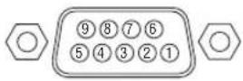
| Pin No. Signal | |
| 1 Unused | |
| 2 | TxD transmission data |
| 3 RxD | reception data |
| 4 Unused | |
| 5 Grounding | |
| 6 Unused | |
| 7 | RTS transmission request |
| 8 CTS | transmission allowed |
| 9 Unused | |
Screen Trigger (Stereo mini)
When the projector is powered ON the screen trigger output sends a low voltage trigger to the screen controller and the screen will go down. When the projector is powered OFF the screen trigger stops sending a low voltage trigger to the screen controller and the screen will go up.
NOTE:
- To use this feature, you must turn on the [TRIGGER-1/2] function. See “TRIGGER-1/2” on page 69 for more information.
Stereo mini cable (not supplied)

NOTE:
- Screen controllers are supplied and supported by screen manufacturers.
NOTE:
- Do not use these terminals for anything other than intended use. Connecting the wired remote control to the TRIGGER 1/2 terminals causes damage to the remote control.
7-6. Troubleshooting
This section helps you resolve problems you may encounter while setting up or using the projector.
| Problem Check These Items | |
| Does not turn on or shut down | Check that the power cord is plugged in and that the power button on the projector cabinet or the remote control is on. (→ pages 13, 15)Check to see if the projector has overheated. If there is insufficient ventilation around the projector or if the room where you are presenting is particularly warm, move the projector to a cooler location.The light module may fail to light. Wait a full minute and then turn on the power again.In case it's hard to think the trouble is not caused on the above mentioned conditions, unplug the power cord from the outlet. Then wait 5 minutes before plugging it in again. |
| Will turn off | Ensure that the [AUTO POWER OFF] is off. (→ page 64) |
| No picture | Check if the appropriate input is selected. (→ page 18) If there is still no picture, press the INPUT button on the projector cabinet or one of the source buttons on the remote control again.Ensure your cables are connected properly.Use menus to adjust the brightness and contrast. (→ page 54)Check that the SHUTTER (lens shutter) button is not pressed.Reset the settings or adjustments to factory preset levels using the [RESET ALL] in the Menu. (→ page 70)If the HDMI 1 IN/HDMI 2 IN or the DisplayPort IN signal cannot be displayed, try the following.- Reinstall your driver for the video card built in your computer, or use the updated driver.For reinstalling or updating your driver, refer to the user guide accompanied with your computer or video card, or contact the support center for your computer manufacturer.Install the updated driver or OS on your own responsibility.We are not liable for any trouble and failure caused by this installation.Signals may not be supported depending on the HDBaseT transmission device. IR and RS232C cannot be used in certain cases as well.Be sure to connect the projector and notebook PC while the projector is in standby mode and before turning on the power to the notebook PC.In most cases the output signal from the notebook PC is not turned on unless connected to the projector before being powered up.* If the screen goes blank while using your remote control, it may be the result of the computer's screen-saver or power management software.See also the page 88. |
| Picture suddenly becomes dark | Check if the projector is in the “Forced ECO MODE” because of too high ambient temperature. |
| Color tone or hue is unusual | Adjust [HUE] in [PICTURE]. (→ page 54) |
| Image isn't square to the screen | Reposition the projector to improve its angle to the screen. (→ page 20)Use the Keystone correction function to correct the trapezoid distortion. (→ page 34) |
| Picture is blurred | Adjust the focus. (→ page 24, 25)Reposition the projector to improve its angle to the screen. (→ page 20)Ensure that the distance between the projector and screen is within the adjustment range of the lens. (→ page 74)Has the lens been shifted by an amount exceeding the guaranteed range? (→ page 77)Condensation may form on the lens if the projector is cold, brought into a warm place and is then turned on. Should this happen, let the projector stand until there is no condensation on the lens. |
| Remote control does not work | Install new batteries. (→ page 10)Make sure there are no obstacles between you and the projector.Stand within 22 feet (7 m) of the projector. (→ page 11) |
| Indicator is lit or blinking | See the POWER/STATUS/LIGHT/TEMP. Indicator. (→ page 89) |
For more information contact your dealer.
If there is no picture, or the picture is not displayed correctly.
- Power on process for the projector and the PC.
Be sure to connect the projector and notebook PC while the projector is in standby mode and before turning on the power to the notebook PC.
In most cases the output signal from the notebook PC is not turned on unless connected to the projector before being powered up.
NOTE:
- You can check the horizontal frequency of the current signal in the projector's menu under Information. If it reads "0kHz", this means there is no signal being output from the computer. (→ page 70 or go to next step)
- Enabling the computer's external display.
Displaying an image on the notebook PC's screen does not necessarily mean it outputs a signal to the projector. When using a PC compatible laptop, a combination of function keys will enable/disable the external display. Usually, the combination of the "Fn" key along with one of the 12 function keys gets the external display to come on or off. For example, NEC laptops use Fn + F3, while Dell laptops use Fn + F8 key combinations to toggle through external display selections.
• Non-standard signal output from the computer
If the output signal from a notebook PC is not an industry standard, the projected image may not be displayed correctly. Should this happen, deactivate the notebook PC's LCD screen when the projector display is in use. Each notebook PC has a different way of deactivate/reactivate the local LCD screens as described in the previous step. Refer to your computer's documentation for detailed information.
• Image displayed is incorrect when using a Mac
When using a Mac with the projector, set the DIPswitch of the Mac adapter (not supplied with the projector) according to your resolution. After setting, restart your Mac for the changes to take affect.
For setting display modes other than those supported by your Mac and the projector, changing the DIP switch on a Mac adapter may bounce an image slightly or may display nothing. Should this happen, set the DIP switch to the 13" fixed mode and then restart your Mac. After that, restore the DIP switches to a displayable mode and then restart the Mac again.
NOTE:
- A Video Adapter cable manufactured by Apple Computer is needed for a MacBook which does not have a mini D-Sub 15-pin terminal.
- Mirroring on a MacBook
* When using the projector with a MacBook, output may not be set to the display resolution of the unit unless "mirroring" is off on your MacBook. Refer to owner's manual supplied with your Mac computer for mirroring.
- Folders or icons are hidden on the Mac screen
Folders or icons may not be seen on the screen. Should this happen, select [View] → [Arrange] from the Apple menu and arrange icons.
7-7. Feature of each indicator

① POWER indicator
This indicator informs the power status of the projector.
② STATUS indicator
This indicator lights/blinks when a button is pressed while the [CONTROL PANEL LOCK] function is utilized, or while performing the [CENTER LENS] and specific operations.
③ LIGHT indicator
This indicator informs the state of light source, used time of the light source, and the status of [LIGHT MODE].
④ TEMP. indicator
This is the temperature indicator informing temperature trouble when the ambient temperature is too high/low.
Indicator Message (Status message)
| POWER STATUS LIGHT TEMP. Projector status | ||||
| Off Off Off | Off | Power is off | ||
 Orange(Blink*1) Orange(Blink*1) | Off Off Off | In the state of Standby ([STANDBY POWER] is [OFF] and the network is not available.) | ||
 Green(Light) Green(Light) | Off Off Off | In the state of Sleep | ||
 Blue(Light) Blue(Light) | Off Green | (Light) | Off | Powered state ([LIGHT MODE] is [NORMAL]) |
 Blue(Light) Blue(Light) | Off Green | (Blink*3) | Off | Powered state ([LIGHT MODE] is [ECO]) |
| Status varies Orange | (Blink*3) | Status varies Off | [CENTER LENS] implement request.(The [CENTER LENS] execution request message is displayed on the screen.) | |
 Blue(Light) Blue(Light) | Green(Blink*3) | Status varies Off | Performing the [CENTER LENS] | |
 Blue(Light) Blue(Light) | Status varies Off | Off | Shutter function is activating | |
 Blue(Blink*4) Blue(Blink*4) | Off Off Off | Preparing for powering ON | ||
| POWER STATUS LIGHT TEMP. Projector status Procedure | ||||
 |  | Status varies Off | A button has been pressed while the [CONTROL PANEL LOCK] is activated. | The [CONTROL PANEL LOCK] is activated. The setting must be canceled to operate the projector. (→ page 69) |
| Blue (Light) | Orange (Light) | |||
| ID numbers for the projector and the remote control do not match. | Check the control IDs (→ page 67) | |||
| Blue (Light) | Off Orange | (Light) | Temperature problem (In the “Forced ECO MODE”) | Ambient temteprature is high. Lower the room temperature. |
*1 Repetition to light on for 1.5 seconds / off for 7.5 seconds
*2 Repetition to light on for 2.5 seconds / off for 0.5 seconds
*3 Repetition to light on for 0.5 seconds / off for 0.5 seconds / on for 0.5 seconds / off for 2.5 seconds
*4 Repetition to light on for 0.5 seconds / off for 0.5 seconds
Indicator Message (Error message)
| POWER STATUS LIGHT TEMP. Projector status Procedure | ||||
 Red(Blink * ^4 ) Red(Blink * ^4 ) | [7KAA]Off Off Off |  | Temperature problem Ambient temperature is out of the operation temperature. Check if any obstruction stays near the exhaust vent. | |
 Red(Blink * ^4 ) Red(Blink * ^4 ) |  Red(Light) Red(Light) | [CHWS]Red(Light) | [47CZ]Off | Lens mounting error/Lens problem Lens is not mounted properly. Mout it.If the indicator message is remain unchanged even if the lens is mounted properly, contact your dealer. |
| [6SHX]Red(Light) |  Status varies Status varies | [4YYG]Status varies |  Off Off | Error requiring service support Contact your dealer or service personnel. Make sure to check and inform indicator status for asking to repair. |
*4 Repetition to light on for 0.5 seconds / off for 0.5 seconds
- When the thermal protector is activated:
When inside temperature of the projector becomes too high or low, the POWER indicator start to red blink in a short cycle. After this happened, the thermal protector will activate and the projector may be turned off.
In this case, please take the below measures:
- Pull out the power plug from the wall inlet.
- Place the projector in cool place if it has been placed in high ambient temperature.
- Clean the exhaust vent if dust has accumulated on.
- Leave the projector for about one hour until inside temperature gets lower.
7-8. PC Control Codes and Cable Connection
PC Control Codes
Function Code Data
| POWER | ON | 02H | 00H | 00H | 00H | 00H | 02H | |||||
| POWER | OFF | 02H | 01H | 00H | 00H | 00H | 03H | |||||
| INPUT | SELECT | HDMI | 1 | 02H | 03H | 00H | 00H | 02H | 01H | A1H | A9H | |
| INPUT | SELECT | HDMI | 2 | 02H | 03H | 00H | 00H | 02H | 01H | A2H | AAH | |
| INPUT | SELECT | COMPUTER | 02H | 03H | 00H | 00H | 02H | 01H | 01H | 09H | ||
| INPUT | SELECT | BNC | 02H | 03H | 00H | 00H | 02H | 01H | 02H | 10H | ||
| INPUT | SELECT | DVI-D | 02H | 03H | 00H | 00H | 02H | 01H | 9CH | A4H | ||
| INPUT | SELECT | DisplayPort | 02H | 03H | 00H | 00H | 02H | 01H | A6H | AEH | ||
| INPUT | SELECT | SDI | 02H | 03H | 00H | 00H | 02H | 01H | C4H | CCH | ||
| INPUT | SELECT | HDBaseT | 02H | 03H | 00H | 00H | 02H | 01H | BFH | C7H |
NOTE:
- Contact your local dealer for a full list of the PC Control Codes if needed.
Cable Connection
Communication Protocol
| Baud rate 9600 bps | |
| Data length 8 bits | |
| Parity No parity | |
| Stop bit | One bit |
| X on/off | None |
| Communications procedure | Full duplex |
NOTE:
- Depending on the equipment, a lower baud rate may be recommended for long cable runs.
PC Control Terminal (D-SUB 9P)

NOTE:
- Pins 1, 4, 6 and 9 are no used.
- Jumper "Request to Send" and "Clear to Send" together on both ends of the cable to simplify cable connection.
7-9. Troubleshooting Check List
Before contacting your dealer or service personnel, check the following list to be sure repairs are needed also by referring to the “Troubleshooting” section in your user’s manual. This checklist below will help us solve your problem more efficiently.
* Print this page and the next page for your check.
Frequency of occurrence □ always □ sometimes (How often?____) □ other (____)
Power
☐ No power (POWER indicator does not light blue). See also “Status Indicator (STATUS)”.
Power cord's plug is fully inserted into the wall outlet. No power even though you press and hold the POWER button. The main power switch is in the "ON (I)" position.
□ Shut down during operation. □ Power cord's plug is fully inserted into the wall outlet. □ [AUTO POWER OFF] is turned off (only models with the [AUTO POWER OFF] function).
Video and Audio
☐ No image is displayed from your PC or video equipment to the projector.
Still no image even though you connect the projector to the PC first, then start the PC.
Enabling your notebook PC's signal output to the projector.
- A combination of function keys will enable/disable the external display. Usually, the combination of the "Fn" key along with one of the 12 function keys turns the external display on or off.
No image (blue or black background, no display).
Still no image even though you press the AUTO ADJUST button.
Still no image even though you carry out [RESET ALL] in the projector's menu.
Signal cable's plug is fully inserted into the input terminal
A message appears on the screen.
( )
The source connected to the projector is active and available.
Still no image even though you adjust the brightness and/or the contrast.
Input source's resolution and frequency are supported by the projector.
☐ Image is too dark.
Remains unchanged even though you adjust the brightness and/or the contrast.
☐ Image is distorted.
Image appears to be trapezoidal (unchanged even though you carry out the [KEYSTONE] adjustment).
Parts of the image are lost.
Still unchanged even though you press the AUTO ADJUST button. Still unchanged even though you carry out [RESET ALL] in the projector's menu.
☐ Image is shifted in the vertical or horizontal direction.
Horizontal and vertical positions are correctly adjusted on a computer signal.
Input source's resolution and frequency are supported by the projector.
Some pixels are lost.
☐ Image is flickering.
Still unchanged even though you press the AUTO ADJUST button. Still unchanged even though you carry out [RESET ALL] in the projector's menu. Image shows flickering or color drift on a computer signal. Still unchanged even though you change [FAN MODE] from [HIGH ALTITUDE] to [AUTO].
☐ Image appears blurry or out of focus.
Still unchanged even though you checked the signal's resolution on PC and changed it to projector's native resolution. Still unchanged even though you adjusted the focus.
Other
□ Remote control does not work.
☐ No obstacles between the sensor of the projector and the remote control.
Projector is placed near a fluorescent light that can disturb the infrared remote controls.
☐ Batteries are new and are not reversed in installation.
Buttons on the projector cabinet do not work (only models with the [CONTROL PANEL LOCK] function) [CONTROL PANEL LOCK] is not turned on or is disabled in the menu.
In the space below please describe your problem in detail.
Information on application and environment where your projector is used
Projector
Model number:
Serial No.:
Date of purchase:
Light module operating time (hours):
Eco Mode: □ OFF □ ON
Information on input signal:
Horizontal synch frequency [ ] kHz
Vertical synch frequency [ ] Hz
Synch polarity H □ (+) □ (−)
V
Synch type □ Separate □ Composite
□ Sync on Green

flowchart
graph LR
    A["Projector"] -->|Cable| B["PC"]
    A --> C["Blu-ray player"]
Signal cable
NEC standard or other manufacturer's cable?
Model number: Length: inch/m
Distribution amplifier
Model number:
Switcher
Model number:
Adapter
Model number:
Installation environment
Screen size: inch
Screen type: □ White matte □ Beads □ Polarization
□ Wide angle □ High contrast
Throw distance: feet/inch/m
Orientation: □ Ceiling mount □ Desktop
Power outlet connection:
□ Connected directly to wall outlet
☐ Connected to power cord extender or other (the number of connected equipment ____ )
☐ Connected to a power cord reel or other (the number of connected equipment ____ )
Computer
Manufacturer:
Model number:
Notebook PC □ / Desktop □
Native resolution:
Refresh rate:
Video adapter:
Other:
Video equipment
VCR, Blu-ray player, Video camera, Video game or other
Manufacturer:
Model number:
NEC



- Important Information......v
- Introduction......1
- Projecting an Image (Basic Operation)....12
- Convenient Features....30
- Using On-Screen Menu....44
- 4-3. INPUT 49
- 4-4. PICTURE 54
- 4-5. DISPLAY....57
- 4-6. SETUP 63
- 4-7. INFO. And RESET ALL....70
- Installation and Connections....71
- Maintenance ....73
- Appendix....74
- Registration Information and Software License
- NOTES
- Safety Cautions
- Precautions
- CAUTION
- Machine Noise Information Regulation - 3. GPSGV,
- WARNING
- Installing the projector
- Laser Safety Caution
- For USA
- For other regions
- Disposing of your used product
- In the European Union
- Outside the European Union
- Important Safeguards
- Installation
- Fire and Shock Precautions
- Caution on Handling the Optional Lens
- Cable information
- Avoid locations with extreme temperatures and humidity
- Precautions when installing or replacing the lens unit sold separately (CENTER LENS)
- Remote Control Precautions
- Light Module
- Label Information
- Laser light radiation range
- Radiation Zone (HD: Hazard Distance)
- Please heed all precaution for safety.
- To install the projector
- To use the projector
- About Copyright of original projected pictures:
- Health precautions to users viewing 3D images
- FCC Information (for USA only)
- Supplier's declaration of conformity
- Other region
- (For Customers in U.K.)
- IMPORTANT
- Clearance for Installing the Projector
- Example 1 – If there are walls on both sides of the projector.
- NOTE:
- Example 2 – If there is a wall behind the projector.
- Example 3 – If there is not much clearance above the projector.
- Precautions for Ceiling Installation
- Introduction
- 1-1. Introduction to the Projector
- General
- - Single-chip DLP projector with high resolution and high brightness
- • Superior dust-proof structure
- Light source · Brightness
- - A long-life laser diode is equipped in the light module
- - Brightness can be adjusted within a wide range
- • [CONSTANT BRIGHTNESS] mode
- - Wide range of optional lenses selectable according to the place of installation
- - This projector can be installed any angle within vertical and horizontal 360° range, however, life of optical parts will be shorten in the following installation state:
- - Power lens control for quick and easy adjustment
- Videos
- Network
- About this user's manual
- 1-2. What's in the Box?
- 1-3. Part Names of the Projector
- Front/Top
- Controls/Indicator Panel
- Terminals Features
- PC CONTROL Port (D-Sub 9 Pin)
- TRIGGER 1/2 Terminal (Stereo Mini)
- 3D SYNC Terminal (Mini DIN 3 Pin)
- 1-4. Part Names of the Remote Control
- Infrared Transmitter
- Remote Jack
- POWER ON Button ( )
- POWER STANDBY Button ( )
- USER 1/2/3 Button
- MENU Button
- EXIT Button
- ▲▼◀▶ Button
- ENTER Button
- FOCUS Button
- SHIFT Button
- ZOOM Button
- VOL./D-ZOOM (+)(−) Button
- DEFAULT Button
- SHUTTER/OSD OPEN (C)
- LIGHT Button
- Geometric. Button
- STATUS Button
- TEST Button
- HDMI1 Button
- HDMI2 Button
- HDBaseT Button
- DP1 Button
- DP2 Button
- SDI Button
- SLOT Button
- COMP. Button
- DVI Button
- AUX Button
- ID SET Button
- Numeric Keypad Button
- CTL Button
- Battery Installation
- Operating Range for Wireless Remote Control
- Using the Remote Control in Wired Operation
- Projecting an Image (Basic Operation)
- 2-1. Flow of Projecting an Image
- Step 1
- Step 2
- Step 3
- Step 4
- Step 5
- Step 6
- Step 7
- 2-2. Connecting Your Computer/Connecting the Power Cord
- Connect your computer to the projector.
- Connect the supplied power cord to the projector.
- Important Information:
- Using the Supplied Power Cords
- Using the Power Cord Stopper
- Attaching the power cord stopper
- 2-3. Turning on the Projector
- Performing Lens Calibration
- About the language of the on-screen menu
- 2-4. Selecting a Source
- Selecting the computer or video source
- Using the Direct button on the remote control
- Using the INPUT button on the projector cabinet
- Select by displaying the On-Screen Menu
- 2-5. Adjusting the Picture Size and Position
- NOTE\*1:
- TIP:
- Adjusting the vertical position of a projected image (Lens shift)
- Adjusting with buttons on the cabinet
- Press the SHIFT ▼▲◀ or ▶ button.
- Adjusting with the remote control
- Press the SHIFT button.
- Press the ▼▲◀ or ▶ button.
- About [CENTER LENS]
- Adjusting the focus and zoom of the projected image
- Applicable lens: NP48ZL/NP49ZL
- Adjust the focus until the image is clear.
- Adjust the zoom until the projected image fits the screen.
- Applicable lens: NP45ZL/NP46ZL/NP47ZL
- Edge focus position for each lens unit
- Focus on the projected image around the optical axis. (Powered focus)
- Adjust the focus at the edges of the projected image. (Manual focus)
- Adjusting the Tilt Foot
- 2-6. Turning off the Projector
- Press the ⓊPOWER) button on the projector cabinet or the POWER STANDBY button on the remote control.
- Press the ⏻POWER) button again.
- Make sure the projector is in STANDBY MODE, then turn off the main power switch "○ (OFF)"
- CAUTION:
- Convenient Features
- 3-1. Turn off the light of the projector (LENS SHUTTER)
- 3-2. Turning Off the On-Screen Menu (On-Screen Mute)
- 3-3. Shift the On-Screen Menu displaying position
- 3-4. Magnifying a Picture
- 3-5. Adjustment of luminance (brightness) and energy-saving effect [LIGHT MODE]
- 3-6. Correcting Horizontal and Vertical Keystone Distortion [KEYSTONE]
- 3-7. Controlling the Projector by Using an HTTP Browser
- Overview
- Possible operations on the HTTP server screen
- To view the HTTP server screen
- Preparation before Use
- Handling of the Address for Operation via a Browser
- 3-8. Storing Changes for Lens Shift [LENS MEMORY]
- To store your adjusted values in [LENS MEMORY]:
- To call up your adjusted values from [LENS MEMORY]:
- To delete your adjusted values from [LENS MEMORY]:
- 3-9. Adjust boundaries of a projected image [EDGE BLENDING]
- Setting the overlap of projection screens
- ① Enable [EDGE BLENDING].
- Press the MENU button.
- Select [DISPLAY] → [EDGE BLENDING].
- Select [MODE] → [ON] and press the ENTER button.
- [BLACK LEVEL]
- Black Level Adjustment
- Select [DISPLAY] → [EDGE BLENDING] → [BLACK LEVEL] and press the ENTER button.
- Use the ◀ or ▶ to adjust the black level.
- TIP: 9-segmented portions for Black Level adjustment
- Using On-Screen Menu
- 4-1. Basic operations of the on-screen menu
- 4-1-1. Configuration of the on-screen menu screen
- Press the ◀/▶ button.
- With the cursor on the main menu tab, press the ▼/▲ button.
- Press the ▼/▲ button to move the cursor to the sub-menu that you want.
- Move the cursor to the sub-menu that you want, then press the ◀/▶ button or ENTER button.
- 4-1-2. Adjustment bar
- 4-1-3. Confirmation message
- 4-1-4. Changing the number
- Press the MENU button and select [SETUP] → [NETWORK SETTINGS].
- 4-2. List of Menu Items
- 4-3. INPUT
- 4-3-1. INPUT SELECTION
- 4-3-2. AUTO SOURCE
- 4-3-3. COLOR SPACE
- 4-3-4. ASPECT RATIO
- 4-3-5. OVERSCAN
- 4-3-6. IMAGE OPTIONS
- 4-3-7. TEST PATTERN
- 4-3-8. 3D
- Health warning
- To avoid adverse health effects, please note the following:
- 4-3-9. AUTO ADJUST
- 4-4. PICTURE
- 4-4-1. PRESET
- 4-4-2. CONTRAST/BRIGHTNESS/SHARPNESS/COLOR/HUE
- 4-4-3. COLOR TEMPERATURE
- 4-4-4. COLOR GAMUT
- 4-4-5. GAMMA CORRECTION
- 4-4-6. WHITE BALANCE
- 4-4-7. COLOR CORRECTION
- 4-4-8. NOISE REDUCTION
- 4-4-9. DYNAMIC CONTRAST
- 4-5. DISPLAY
- 4-5-1. LENS LOCK
- 4-5-2. LENS CONTROL
- 4-5-3. LENS MEMORY
- 4-5-4. CENTER LENS
- 4-5-5. DIGITAL ZOOM
- 4-5-6. GEOMETRIC CORRECTION
- KEYSTONE
- ROTATION
- PINCUSHION / BARREL
- ARC
- TOP LEFT CORNER
- TOP RIGHT CORNER
- BOTTOM LEFT CORNER
- BOTTOM RIGHT CORNER
- PC TOOL
- 4-5-7. BLANKING
- 4-5-8. EDGE BLENDING
- 4-5-9. SCREEN TYPE
- 4-6. SETUP
- 4-6-1. LANGUAGE
- 4-6-2. ORIENTATION
- 4-6-3. FAN MODE
- 4-6-4. AUTO POWER OFF
- 4-6-5. DIRECT POWER ON
- 4-6-6. NETWORK SETTINGS
- 4-6-7. LIGHT MODE
- 4-6-8. LIGHT ADJUST (LIGHT MODE)
- 4-6-9. CONSTANT BRIGHTNESS (LIGHT MODE)
- 4-6-10. BACKGROUND
- 4-6-11. STARTUP LOGO
- 4-6-12. REMOTE CONTROL
- How to set/change the ID in the remote control
- 4-6-13. TRIGGER-1/2
- 4-7. INFO. And RESET ALL
- 4-7-1. INFO.
- 4-7-2. RESET ALL
- Installation and Connections
- 5-1. Connecting to Other Equipment
- ① HDMI cable (not supplied)
- ② DisplayPort cable (not supplied)
- ③ BNC cable (not supplied)
- ④ LAN cable (not supplied)
- ⑤ Computer cable (mini D-sub 15 pin) (not supplied)
- ⑥ DVI-D cable (not supplied)
- Maintenance
- 6-1. Cleaning the Lens
- 6-2. Cleaning the Cabinet
- Appendix
- 7-1. Throw distance and screen size
- Lens types and throw distance
- Lens shifting range
- 7-2. Compatible Input Signal List
- 7-4. Cabinet Dimensions
- 7-5. Pin assignments and signal names of main terminals HDMI 1 IN/HDMI 2 IN Terminal (Type A)
- HDBaseT/LAN Port (RJ-45)
- PC CONTROL Port (D-Sub 9 Pin)
- Screen Trigger (Stereo mini)
- 7-6. Troubleshooting
- If there is no picture, or the picture is not displayed correctly.
- 7-7. Feature of each indicator
- 7-8. PC Control Codes and Cable Connection
- PC Control Codes
- Cable Connection
- Communication Protocol
- PC Control Terminal (D-SUB 9P)
- 7-9. Troubleshooting Check List
- Power
- Video and Audio
- Other
- Information on application and environment where your projector is used
- Projector
- Signal cable
- Installation environment
- Computer
- Video equipment
Brand : SHARP
Model : PX2201UL
Category : Video projector