
2140R - Measurement Daytronic - Free user manual and instructions
Find the device manual for free 2140R Daytronic in PDF.


| Product Type | Signal Conditioning and Data Acquisition System |
| Model | 2140R |
| Brand | Daytronic |
| Dimensions | 19-inch rack mount, 3U height (approx. 132.5 mm x 482.6 mm x 250 mm) |
| Weight | Approximately 5.5 kg (12.1 lbs) |
| Power Supply | 100-240 VAC, 50/60 Hz, 100W max |
| Main Functions | Analog input channels (up to 16), signal conditioning (amplification, filtering, isolation), A/D conversion, data logging, real-time monitoring, and support for various transducers (strain gauges, thermocouples, LVDTs) |
| Input Channels | 16 differential analog inputs with software-selectable gain and filtering |
| Communication Interface | Ethernet, RS-232, USB (optional) |
| Display | Front panel LCD (2-line, 16-character) with keypad for local operation |
| Sampling Rate | Up to 1000 samples per second per channel (aggregate) |
| Accuracy | 0.1% of full scale typical |
| Operating Environment | 0°C to 50°C, 10-90% RH non-condensing |
| Maintenance and Cleaning | Periodic calibration recommended every 12 months; clean exterior with dry cloth; keep vents free of dust |
| Safety | Overvoltage protection on inputs; CE compliant; designed for indoor use only |
| Spare Parts and Repairability | Contact Daytronic for spare parts (e.g., power supply, input modules); repair service available from factory-authorized centers |
| General Information | User manual included; software provided for PC configuration and data logging; supports multiple sensor types |
Frequently Asked Questions - 2140R Daytronic
User questions about 2140R Daytronic
0 question about this device. Answer the ones you know or ask your own.
Ask a new question about this device
Download the instructions for your Measurement in PDF format for free! Find your manual 2140R - Daytronic and take your electronic device back in hand. On this page are published all the documents necessary for the use of your device. 2140R by Daytronic.
USER MANUAL 2140R Daytronic
Daytronic Corporation
2. TABLE OF CONTENTS
- ORDERING GUIDE ...... 2
- TABLE OF CONTENTS.... 3
- PRODUCT INTRODUCTION.... 4
- RECEIVING & UNPACKING 5
- SAFETY CONSIDERATIONS.... 5
- CONNECTOR AIRING INFORMATION 6
- MECHANICAL ASSEMBLY 8
- FRONT PANEL SETUP KEYS 10
- ENABLING & LOCKING OUT MENU ITEMS 12
- DUAL CHANNEL PULSE OR AC INPUT SIGNAL CONDITIONER (FR) 13
- PROCESS RECEIVER & TOTALIZER SIGNAL CONDITIONER (VF).... 30
- QUADRATURE SIGNAL CONDITIONER (QD) 37
- SERIAL INPUT METER / REMOTE DISPLAY (NO SIGNAL CONDITIONER)....53
- DUAL & QUAD RELAY OUTPUT OPTIONS 55
- SINGLE & DUAL ANALOG OUTPUT OPTIONS 58
- SERIAL COMMUNICATION OPTIONS 60
- EXCITATION OUTPUT & POÄER SUPPLY 65
- INSTRUMENT SETUP VIA PC....66
- CUSTOM CURVE LINEARIZATION....69
- METER CALIBRATION 71
- SPECIFICATIONS....72
- GLOSSARY OF TERMS....75
- ĀARRANTY 80
3. PRODUCT INTRODUCTION
Our counters are a versatile, cost effective solution to a wide range of monitoring and control applications including frequency, rate, total, period, time, phase, position, and flow. Setup can be via front panel pushbuttons or a PC. Selective lockout of front panel keys protects against accidental or unauthorized setup changes and simplifies meter use.
A dual-channel pulse or AC input signal conditioner board accommodates a wide range of applications including rate/frequency, totalizing, timing, phase angle, power factor, and duty cycle. Frequency and rate are determined by taking the inverse of period. Fast read rate is ideal for peak or valley capture and allows quick response for control applications. Adaptive digital filtering provides stable readings and control outputs while responding rapidly to actual changes of the signal. A high stability quartz crystal and digital calibration assure accurate rate and analog measurements.
A process receiver & totalizer signal conditioner board accepts 4-20 mA, 0-1 mA or 0-10V analog signals for display of rate or position. Square root extraction is selectable for use with differential pressure flow transducers.
A quadrature signal conditioner board provides accurate display of position, angle, or rate.
USB, RS232, or RS485 (2-wire half-duplex or 4-wire full-duplex) serial communications options are available with the Modbus protocol or a simpler custom ASCII protocol. Modbus operation includes RTU or ASCII modes, up to 247 digital addresses, and up to 32 devices per RS485 line without a repeater. USB-to-RS485 converter boards allow a meter to be interfaced to a PC and to multiple meters on an RS485 network
Meter programming can be via the meter's front panel or a PC running Windows based Instrument Setup Software. A serial interface option is required.
A standard switching power supply allows the meters to be powered worldwide from 85 to 264 Vac. An optional power supply operates from batteries or low voltage sources, such as 12-32 Vac.
A built-in isolated excitation supply with jumper-selectable 5, 10 or 24 Vdc output levels is standard and can eliminate the need for an external sensor power supply.
A dual or quad relay board is optional for alarm or control. The relays can be Form C 8A mechanical relays or 2 or 4 Form A 130 mA solid state relays. The setpoints can be latching or non-latching, be energized above or below the setpoint, or operate in a fail-safe mode.
A single or dual isolated analog output board is optional. Āith dual outputs, one of the outputs can be assigned to the reading (such a rate), while other reading is assigned a non-displayed item (such as total). The outputs can be 0-20 mA, 4-20 mA, 0-10V, or -10V to +10V.
Operation as a 6-digit serial input meter is achieved with a serial interface and no signal conditioner board, allowing the unit to serve as the remote display of a computer, PLC or other meter. Āith an optional dual or quad relay board, the unit can provide local alarm or On/Off control. Āith an optional analog output board, it can also serve as a local isolated transmitter.
The meter case meets the 1/8 DIN size standard and is sealed to NEMA-4X (IP65) when panel mounted. Mounting is from the front of the panel and requires less than 110 mm behind the panel. All wiring is via removable plugs conforming to IEC950 safety standards. All output options are isolated from meter and power grounds to 250 Vac.
4. RECEIVING & UPACKING
Your meter was carefully tested and inspected prior to shipment. Should the meter be damaged in shipment, notify the freight carrier immediately. In the event the meter is not configured as ordered or the unit is inoperable, return it to the place of purchase for repair or replacement. Please include a detailed description of the problem.
5. SAFETY CONSIDERATIONS

Warning: Use of this equipment in a manner other than specified may impair the pro-on of the device and subject the user to a hazard. Visually inspect the unit for signs of age. If the unit is damaged, do not attempt to operate.
Caution:
- The unit must be connected to a Disconnect switch or a branch-circuit breaker, which must be in a suitable location
- This unit must be powered with AC (mains) from 85-264 Vac with the high voltage power supply option, or 10-48 Vdc (12-32 Vac) with the low voltage power supply option. Verify that the proper power option is installed for the power to be used. This meter has no AC (mains) switch. It will be in operation as soon as power is connected.
- The 85-264 Vac mains connector (P1 Pins 1-3) is colored Green to differentiate it from other input and output connectors. The 12-32 Vac (10-48 Vdc) mains connector is colored Black.
- Do not make signal wiring changes or connections when power is applied to the instrument. Make signal connections before power is applied. If reconnection is required, disconnect the AC (mains) power before such wiring is attempted.
- To prevent electrical or fire hazard, do not expose the instrument to excessive moisture.
- Do not operate the instrument in the presence of flammable gases or fumes; such an environment constitutes a definite safety hazard. This meter is designed to be mounted in a metal panel or a bench or wall mount style case. The spacing around the meter and the ventilation must be sufficient to maintain the ambient temperature at less than 55° C.
- Verify the panel cutout dimensions, and mount according to instructions.
Symbols used

Caution (refer to accompanying documents)
Caution, risk of electric shock.
Equipment protected throughout by double insulation or reinforced insulation.

Earth (ground) terminal.
Both direct and alternating current.
Operating environment:
The meter is Class II (double insulated) equipment designed for use in Pollution degree 2.
6. CONNECTOR WIRING INFORMATION
CONNECTORS
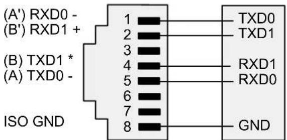
Connectors for signal and power are U/L rated screw-clamp terminal blocks that plug into mating jacks on the printed circuit board. Communication connectors are a single RJ11 plug for RS232, dual RJ11 plugs for RS485, and dual RJ45 plugs for RS485-Modbus.

P1 - POWER AND DIGITAL CONTROLS

CONTROL INPUT 2 (+5V)* CONTROL INPUT 1* DIGITALGROUND

* Note: external control inputs 1 and 2 are menu selectable.
Caution: P1, pins 4, 5, and 6 may have hazardous voltages present.
P5 - SIGNAL INPUT
VOLTAGE-TO-FREQUENCYCONVERTER

QUADRATURE INPUT (DIFFERENTIAL)

Note: Z input or excitation is jumper selectable
DUAL CHANNEL PULSE INPUT

Ground pins 4 & 6 are internally connected.
QUADRATURE INPUT (SINGLE-ENDED)
Select 5V or 10V excitation to match encoder.

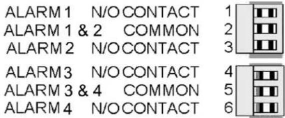
P2 - SETPOINT CONTROLLER
DUAL MECHANICAL RELAY OUTPUTS
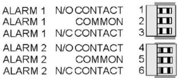
QUAD MECHANICAL RELAY OUTPUTS

DUAL SOLID STATE RELAY OUTPUTS

QUAD SOLID STATE RELAY OUTPUTS
P3 - SERIAL COMMUNICATIONS
RS232 INTERFACE

RS485 INTERFACE - FULL DUPLEX

P4 - ANALOG OUTPUT
UNIPOLAR (SINGLE OR DUAL)

RS485 INTERFACE - HALF DUPLEX

RS485-MODBUS - FULL DUPLEX RS485-MODBUS - HALF DUPLEX

7. MECHANICAL ASSEMBLY
REMOVING THE REAR PANEL
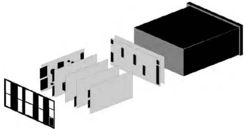
First remove any connectors. Use one hand to press in the two sides of the rear of the case, and the other hand to press down the two protruding tab releases at the top of the rear panel (see figure below). This will unhook the rear panel from the case.

REMOVING THE ELECTRONICS
Aith the rear panel removed, grasp the power supply board to the left and signal conditioner board to the right, then carefully slide the electronic assembly out through the rear of the case.
natural_image
Exploded view diagram of a modular device with black and white panels, no text or symbols presentINSTALLING NEW OPTION BOARDS
Options boards plug into the main board at the front of the meter. These are plug-and-play and may be installed in the field. They will be recognized by the software, which will provide access to the menu items associated with that board. If necessary, remove rear panel knockouts for new boards. Boards plug into connectors as follows:
| Option Board Main Board | Plug Rear Panel Jack | |
| Power supply | P11 | J1 |
| Relay board | P12 | J2 |
| Serial interface board | P13 | J3 |
| Analog output board | P14 | J4 |
| Signal conditioner board | P15 | J4 |
Note: Corresponding main board and option board connectors have the same number of electrical lines. Âhen an option board is correctly installed, the top and bottom edges of the main board and option board are aligned.
REASSEMBLING YOUR METER
Slide the electronics assembly into the case until the display board is seated flush against the front overlay. Insert the bottom tabs of the rear panel into the case, then carefully align the board connectors with the openings in the rear panel. If necessary, remove any rear panel knockouts for new option boards that may have been installed. Ensure that all option boards are properly aligned with the molded board retaining pins on the inside of the rear panel. Once the rear panel is in place, reinstall the input/output screw clamp terminal plugs.
PANEL MOUNTING
Ensure that the panel mounted gasket is in place against the back of the bezel. Turn the two mounting screws counterclockwise until the space between the mounting pawl and the rear of the gasket is greater than the panel thickness. Insert the meter in the panel cutout. Turn the mounting screws clockwise until the meter is securely mounted in the panel. Do not overtighten.
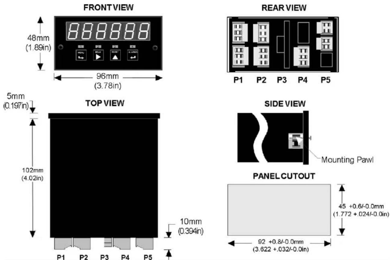
Dimensioned case drawings
8. FRONT PANEL SETUP KEYS

There are four front panel keys, which change function for the Run Mode and Menu Mode, effectively becoming eight keys. The keys are labeled with alphanumeric captions (MENU, PEAK, RESET, ALARMS) for the Run Mode and with symbols (→ right arrow, ▶ right triangle, ▲up triangle, ← left arrow) for the Menu Mode.
FRONT PANEL LOCKOUT
The Menu Mode will not work with most meters shipped from the factory, since all menu items have been disabled in software and a lockout jumper is in place. This jumper needs to be removed for the Menu Mode to work, and values under Loc 1 through Loc 4 need to be set to "0" via the front panel for these menu items to be available. See Section 9. The paragraphs below assume that all lockout features have been removed.
MENU MODE KEY ACTION
In the Menu Mode, pressing a key momentarily advances to the next item. Holding down the key advances through multiple menu items for fast menu navigation.
KEYS IN RUN MODE

MENU Key. Pressing MENU from the Run Mode enters the Menu Mode. Pressing MENU repeatedly will step the meter through the various menu items (if these have not been locked out) and then back to the Run Mode.

PEAK Key. Pressing PEAK causes the peak value of the input signal to be displayed. The peak display blinks to differentiate it from the normal present value display. Pressing PEAK again will return the display to the present value.

RESET Key. Pressing RESET with PEAK resets peak and valley values. Pressing RESET with ALARMS resets latched alarms. Pressing RESET with MENU performs a meter reset (same as power on). Pressing and releasing RESET without pressing another key changes the displayed item if the mode has multiple items. For Item 1, the V LED is out. For Item 2, the V LED is on. For Item 3, the V LED is flashing.

ALARMS Key. Pressing ALARMS once displays the setpoint for Alarm 1. Pressing it again displays the setpoint for Alarm 2. Pressing it again returns to the present value. After 30 seconds, the meter automatically returns to the present value. Timing is automatically reset whenever the ALARMS key is pressed.
KEYS IN MENU MODE

Right Arrow Key (MENU). Pressing → steps the meter through all menu items that have been enabled and then back to the Run Mode. Aith the dual-channel pulse input signal conditioner board and no option boards, available menu items will be InPut, SEtuP, ConFiG, dSPYno, etc. Actual menu items will vary depending on the Input selection and boards detected in the meter. If a change has been made to a menu item, that change is saved to non-volatile memory when the key is pressed next, and StoreE is displayed briefly.

Right Triangle Key (Digit Select).
- Pressing ▶ from the InPut menu brings up all meter functions available with the meter's signal conditioner. For the dual-channel pulse input signal conditioner, these are rAtE, PEriod, totAL, i Int, Stop t, PHASE, duty C.
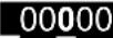
- Pressing from most menus selections sequentially selects digit positions 1 - 6, as indicated by a flashing digit: 000000, 000000, 000000, 000000, 000000, 000000.
- Pressing ▶ from dEC.Pt1 brings up a decimal point display of type 11.1111. Pressing ▶ from dEC.Pt2 brings up a decimal point display of type 22.2222.

Up Triangle Key (Value Select).
- Pressing ▲ from a selected meter function, such as rAtE, will select the a specific operating mode within that function, such as _OnLy Always press the MENU key to save your selection. Do not press the ▲key to the right, or your selection will be lost.
- Pressing for a flashing digit position or decimal point position will increment that item. Pressing the MENU key will save any changes.

Left Arrow Key (Reverse Menu). Pressing ← has the same effect as the MENU key, except that menu items are brought up in reverse order.
9. ENABLING & LOCKING OUT MENU ITEMS
For security reasons and ease of operation, any and all menu items may be disabled or "locked out" so that they are no longer directly accessible from the front panel. Each function to be enabled is set to "0" and each function to be disabled is set to "1" in menu items Loc 1-4. These menu items can in turn be locked out by installing an internal hardware jumper. Āith the jumper installed, the operator only has access to enabled menu items. Āith the jumper removed, the operator also has access to the Loc 1-4 menu items.
SETTING HARDWARE LOCKOUT JUMPER
To access the lockout jumper, remove the rear panel per Section 9 and locate jumper "a" in the lower portion of the power supply board next to the input connectors (see figure at right).
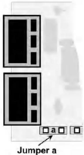
SETTING SOFTWARE LOCKOUTS
Ahen setting up the meter, it may be necessary to enable specific menu items by setting the corresponding lockout digit to 0. Be sure to reset the lockout digit to "1" if you do not want the menu item to be changed by an operator.
Loc 1 Loc 2 Loc 3 Loc 4
Press the MENU key until Loc 1, Loc 2, Loc 3 or Loc 4 is displayed, as desired. Note: the lockout jumper must be removed (see above).
111111
Press ▶ to display the lockout status, consisting of 0's and 1's. The left digit will flash. Press ▶ again to step to the next digit, which will flash.
000000 123456
Press ▲ to set the flashing digit to "0" to enable the menu item or to "1" to disable. Press MENU to enter. See the table to the right for list of menu items that can be enabled or disabled.
Enabled / Disabled Menu Items
Loc 1
3 - Input type selection
4 - Setup, Config, Dspyno
5 - Gate time, timeout, batch setup
6 - Filter setup
Loc 2
3 - Slope, decimal points
4 - Scale, offset, resolution, 2-coord.
5 - Alarm config, DevHy
6 - Alarm setpoint programming
Loc 3
3 - Analog output setup & scaling
4 - Serial communications configuration
5 - Calibration
6 - Change displayed Item #
Loc 4
3 - View peak value
4 - View alarm setpoints
5 - Front panel resets (peak & latched alarms)
6 - Front panel reset (cold reset only)
10. DUAL CHANNEL PULSE OR AC INPUT SIGNAL CONDITIONER
The dual channel signal conditioner board is used for the frequency, rate, period, timing, batch control, phase and duty cycle meter functions. The board needs to be configured via jumpers for the input signal type and level. It is recognized by the meter software, which will bring up the applicable menu items. The dual channel pulse input signal conditioner does not require calibration, since the quartz crystal oscillator used for frequency and timing applications is located on the counter main board.

flowchart
graph TD
    subgraph Channel A
        A1["a"] --> B0["b"]
        A2["a"] --> B3["b"]
        A3["a"] --> B4["b"]
        A4["a"] --> B0["b"]
    end
    subgraph Channel B
        B0["a"] --> B1["b"]
        B1["a"] --> B3["b"]
        B2["a"] --> B4["b"]
    end
    subgraph Channel B_A4
        A4["a"] --> B0["b"]
        A5["a"] --> B1["b"]
        A6["a"] --> B2["b"]
        A7["a"] --> B3["b"]
        A8["a"] --> B4["b"]
    end
    B0 --> A1
    B1 --> A1
    B2 --> A2
    B3 --> A2
    B4 --> A3
    B0 --> A0["a"]
    A1 --> A0
    A2 --> A0
    A3 --> A0
    A4 --> A0
Note: Letters indicate jumper position. Jumpers are installed on pins adjacent to letters.
Jumper Settings for Expected Signal Levels
The jumper settings for Channel A (A2 & A3) and Channel B (B2 & B3) need to be set for the expected signal voltage. This voltage must be outside of the high and low thresholds per the following table, or the meter will not operate properly. The larger the difference between the high and low thresholds, the more immune the meter is to input signal noise.
| A3B3 | A2B2 | Input must be Input must be | A3B3 | A2B2 | be Input must be | A3B3 | A2B2 | ||||
| below | above | below | above | below | above | ||||||
| - | a | -12 mV | +12 mV | a | a | +30 mV | +60 mV | b | a | -60 mV | -30 mV |
| - | b | -150 mV | +150 mV | a | b | +350 mV | +600 mV | b | b | -600 mV | -350 mV |
| - | - | -1.15V | +1.15V | a | - | +1.25V | +2.1V | b | - | -2.1V | -1.25V |
Jumper Settings for Frequency Response, Bias Resistor, Debounce Time
Pull-up or pull-down resistors are used with open collector devices and dry contact closures to provide input signal bias. They should not be connected for other inputs. Debounce circuitry keeps the meter from counting extra pulses due to contact bounce.
| Function Block Jumper | Setting | ||
| Frequency Response | A0 & B0 | -ba | 1 MHz max30 kHz max250 Hz max |
| Bias Resistor A1 & B1 | ab | 10 kOhm pull-up to 5V10 kOhm pull-down to -5V | |
| Contact Debounce | A4 & B4 | ba, cc | None3 msec50 msec |
Common Jumper Settings
| Input Type Vmax | A0 & B0 | A1 & B1 | A2 & B2 | A3 & B3 | A4 & B4 | |
| Logic levels 250V - - - | a b | |||||
| NPN open collector NA | b a - a b | |||||
| PNP open collector NA | b b - b b | |||||
| Contact closures NA a | or b a - a | a, c | ||||
| Line frequency 250V b | - - - a, c | |||||
| Turbine flow meter | 250V b | - a - b |
Frequency in Hz is determined by timing an integral number of pulses over a user-specified gate time from 0 to 199.99 sec and taking the inverse of average period. The typical display update rate of the meter is gate time + 1 period + 30 ms Selecting a longer gate time produces a more stable reading as more cycles are averaged, but slows down the update rate. At very low frequencies, the update rate is controlled by the period. A time-out from 0 to 199.99 sec is also selectable. This is the time the meter waits for a signal to start or end a conversion. If the signal is not received before the time-out ends, the meter reads zero. The longer the time-out, the lower the minimum frequency the meter can display.
Aith a scale factor of 1 and multiplier of 1, frequency is displayed in Hz with no decimal point. Applying a multiplier from 1 to 100000 (in decade steps) and setting the decimal point increases resolution (0.1 to 0.00001 Hz). Decreasing the multiplier from 1 to 0.00001 (in decade steps) and setting the decimal point allows display in kHz or MHz. Note that the same 100 kHz frequency can be displayed as 100000 Hz or 100.000 kHz simply by moving the decimal point.
DISPLAY FREQUENCY IN Hz WITH 1 Hz RESOLUTION
| Dig. No. | S | 1 | 2 | 3 | 4 | 5 | 6 | ||||||
| InPut | r | A | t | E | A | O | n | L | y | ||||
| SEtuP | 0 | 0 | 0 | 0 | 0 | ||||||||
| ConFiG | 1 | 0 | 0 | 0 | |||||||||
| dSPyno | 0 | 1 | |||||||||||
| GAtE t | 0 | 0 | 0. | 2 | 2 | ||||||||
| ti Out | 0 | 0 | 1. | 0 | 0 | ||||||||
| FiLtEr | 0 | 0 | 1 | 0 | 5 | ||||||||
| SLOPE | 0 | 1 | |||||||||||
| DecPt1 | 1 | 1 | 1 | 1 | 1 | 1. | |||||||
| SCALE1 | 1. | 0 | 0 | 0 | 0 | 0 | 1 | ||||||
| OFFSt1 | 0 | 0 | 0 | 0 | 0 | 0 | Do Not Change Calib | ||||||
| CALib | - | 0 | 0 | 0 | 0 | 0 | |||||||
Application: Display frequency from 1 Hz to 999999 Hz with no decimal, display update rate of 4/sec, and adaptive moving average filter for 6 readings.
Solution: Set Input to "Rate A Only." Set Config to display to 999999 counts. Set Gate Time to .22 sec so that the display update rate becomes .22 sec +30 ms +1 period. Set Time-out to 1 sec, so that frequencies under 1 Hz are displayed as 0. Set filter for adaptive moving average with a 1.6 sec time constant. Apply a scale value of 1.00000 and multiplier of 1 for direct readout in Hz.
DISPLAY 0-50.00 RATE FROM 1-10 kHz INPUT, COORDINATES OF 2 POINTS METHOD
| Dig. No. | S | 1 | 2 | 3 | 4 | 5 | 6 | ||||||
| InPut | r | A | t | E | A | O | n | L | y | ||||
| SEtuP | 0 | 0 | 1 | 0 | 0 | ||||||||
| ConFiG | 1 | 0 | 0 | 0 | |||||||||
| dSPyno | 0 | 1 | |||||||||||
| GAtE t | 0 | 0 | 0. | 2 | 2 | ||||||||
| ti Out | 0 | 0 | 1. | 0 | 0 | ||||||||
| FiLtEr | 0 | 0 | 1 | 0 | 5 | ||||||||
| SLOPE | 0 | 1 | |||||||||||
| DecPt1 | 1 | 1 | 1 | 1. | 1 | 1 | |||||||
| Lo In1 | 0 | 0 | 1 | 0 | 0 | 0 | |||||||
| Lo rd1 | 0 | 0 | 0 | 0. | 0 | 0 | |||||||
| Hi In1 | 0 | 1 | 0 | 0 | 0 | 0 | |||||||
| Hi rd1 | 0 | 0 | 5 | 0. | 0 | 0 | |||||||
| CALib | - | 0 | 0 | 0 | 0 | 0 | Do Not Change Calib | ||||||
Application: Display 0-50.00 (with two decimal places) for 1-10 kHz input. Use coordinates of 2 points scaling method.
Solution: Set Input to "Rate A Only." Select "coordinates of 2 points" scaling method under Setup. This is easier than scale and offset. Set DecPt1 to two places. Then enter the low input and desired low reading, and high input and desired high reading, as shown.
DISPLAY RATE IN GPM FROM 36.67 PULSE/GALLON TURBINE FLOW METER
| Dig. No. | S | 1 | 2 | 3 | 4 | 5 | 6 | ||||||
| InPut | r | A | t | E | A | O | n | L | y | ||||
| SEtuP | 0 | 0 | 1 | 0 | 0 | ||||||||
| ConFiG | 1 | 0 | 0 | 0 | |||||||||
| dSPyno | 0 | 1 | |||||||||||
| GAtE t | 0 | 0 | 0. | 2 | 2 | ||||||||
| ti Out | 0 | 0 | 0. | 1 | 0 | ||||||||
| FiLtEr | 0 | 0 | 1 | 0 | 5 | ||||||||
| SLOPE | 0 | 1 | |||||||||||
| DecPt1 | 1 | 1 | 1 | 1. | 1 | 1 | |||||||
| Lo In1 | 0 | 0 | 0 | 0 | 0 | 0 | |||||||
| Lo rd1 | 0 | 0 | 0 | 0. | 0 | 0 | |||||||
| Hi In1 | 0 | 0 | 3 | 6. | 6 | 7 | |||||||
| Hi rd1 | 0 | 0 | 6 | 0. | 0 | 0 | |||||||
| CALib | - | 0 | 0 | 1 | 0 | 0 | Do Not Change Calib | ||||||
Application: Display rate in GPM to two decimal places from flow meter calibrated to 36.67 pulses/gallon.
Solution: Set Input to "Rate A Only. Under Setup, select "coordinates of 2 p oints" scaling method. Set DecPt1 to two places. Then enter the low input and desired lo reading, and high input and desired high reading, as shown. In this example, we want to display 60.00 (GPM) from an input of 36.67 Hz. Note that the meter's nativ rate measurements are in Hz. There will be 60 times more gallons per minute than per second.
Rate in engineering units is displayed from measured frequency by applying an appropriate scale factor and setting the decimal point. The scale factor consists of a scale value from 0.00000 to 9.99999 (fixed decimal point and settable digits) and a scale multiplier from 0.00001 to 100000 (in decade steps). Åhen using the coordinates of 2 points method to scale the meter, the low input and high input frequencies are entered in Hz.
- RATE A ONLY (A_OnLy) displays rate or frequency for Channel A. The latter utilizes SCALE1, OFFSt1 and dECPt1. Channel B is not used.
- RATE A B (A_b_) displays rate or frequency for Channel A as Item #1 or for Channel B as Item #2. The latter utilizes SCALE2, OFFSt2 and dECPt2.
-
RATE A, TOTAL A (A_Atot) (Extended counter) displays Rate for Channel A as Item #1 and Total for Channel A as Item #2 since last reset. Total may count down from an offset by entering a negative scale factor. Only used for non-linear inputs.
-
RATE A, TOTAL B (A_btot) (Extended counter) displays Rate for Channel A as Item #1 and Total for Channel B as Item #2.
- RATES A+B, A-B, AxB, A/B, A/B-1 (Extended counter) display arithmetic combinations of Rates A and B as Item #1, Rate A as Item #2, and Rate B as Item #3. Āith rates A and B scaled to produce a ratio close to 1 and an offset of -1, the special combination A/B-1, called “Draw,” can display percentage changes, such as elongation of material as it passes between rollers.
TOTAL MODES
DISPLAY TOTAL IN GALLONS FROM 36.67 PULSE/GALLON TURBINE FLOW METER
| Dig. No. | S | 1 | 2 | 3 | 4 | 5 | 6 | ||||||
| InPut | t | o | t | A | L | A | O | n | L | y | |||
| SEtuP | 1 | 0 | 1 | 0 | 0 | ||||||||
| ConFiG | 1 | 0 | 0 | 0 | |||||||||
| dSPyno | 0 | 1 | |||||||||||
| GAtE t | 0 | 0 | 0. | 0 | 1 | ||||||||
| SLOPE | 0 | 1 | |||||||||||
| DecPt1 | 1 | 1 | 1 | 1. | 1 | 1 | |||||||
| Lo In1 | 0 | 0 | 0 | 0 | 0 | 0 | |||||||
| Lo rd1 | 0 | 0 | 0 | 0. | 0 | 0 | |||||||
| Hi In1 | 0 | 0 | 3 | 6. | 6 | 7 | |||||||
| Hi rd1 | 0 | 0 | 0 | 1. | 0 | 0 | |||||||
| CALib | - | 0 | 0 | 0 | 0 | 0 | Do Not Change Calib | ||||||
Application: Display total in gallons with two decimal places for flow meter calibrated to 36.67 pulses/gallon.
Solution: Set Input to "Total A Only." Under Setup, select "Restore totals at power-on" and coordinates of 2 points method. This is the preferred scaling method. Se gate time to its minimum of 0.01 sec fo smooth display updates. Set DecPt1 to two places. Then enter low input and desired low reading, and high input and desired high reading for display of 1.00 for 36.6 pulses, as shown.
DISPLAY SIMULTANEOUS RATE & TOTAL FROM 36.67 PULSE/GALLON FLOW METER
| Dig. No. | S | 1 | 2 | 3 | 4 | 5 | 6 | ||||||
| InPut | r | A | t | E | A | A | t | o | t | ||||
| SEtuP | 1 | 0 | 1 | 1 | 0 | ||||||||
| ConFiG | 1 | 1 | 0 | 0 | |||||||||
| dSPyno | 0 | 1 | |||||||||||
| GAtE t | 0 | 0 | 0. | 1 | 0 | ||||||||
| ti Out | 0 | 0 | 1. | 0 | 0 | ||||||||
| FiLtEr | 0 | 0 | 1 | 0 | 5 | ||||||||
| SLOPE | 0 | 1 | |||||||||||
| DecPt1 | 1 | 1 | 1 | 1. | 1 | 1 | |||||||
| DecPt2 | 2 | 2 | 2 | 2 | 2 | 2. | |||||||
| Lo In1 | 0 | 0 | 0 | 0 | 0 | 0 | |||||||
| Lo rd1 | 0 | 0 | 0 | 0. | 0 | 0 | |||||||
| Hi In1 | 0 | 0 | 3 | 6. | 6 | 7 | |||||||
| Hi rd1 | 0 | 0 | 6 | 0. | 0 | 0 | |||||||
| Lo In2 | 0 | 0 | 0 | 0 | 0 | 0 | |||||||
| Lo rd2 | 0 | 0 | 0 | 0 | 0 | 0 | |||||||
| Hi In2 | 0 | 0 | 3 | 6. | 6 | 7 | |||||||
| Hi rd2 | 0 | 0 | 0 | 0 | 0 | 1 | |||||||
| CALib | - | 0 | 0 | 0 | 0 | 0 | Do Not Change Calib | ||||||
Application: Display flow rate in GPM with two decimal places and total gallons with no decimal places from the same flow meter signal calibrated to 36.36 pulses/gallon, applied to Channel A
Solution: Use an Extended counter, as required for simultaneous rate and total. Set Input to "Rate A A Total." For flow rate in GPM (Item #1), set DecPt1 to two decimals, and scale the display by entering Lo In1, Lo rd1, Hi In1, Hi rd1 as shown. F total in Gallons (Item #2), set DecPt2 to no decimals, and scale the display by entering Lo In2, Lo rd2, Hi In2, Hi rd2 as showr Enter a Gate Time, such as 0.1 sec, which is long enough to produce stable rate readings, but is short enough to produce rapid updates of total.
DISPLAY TOTAL VOLUME BY ADDING TWO TURBINE FLOW METER CHANNELS
| Dig. No. | S | 1 | 2 | 3 | 4 | 5 | 6 | |||||
| InPut | t | o | t | A | L | A | + | b | ||||
| SEtuP | 1 | 0 | 1 | 1 | 0 | |||||||
| ConFiG | 1 | 1 | 0 | 0 | ||||||||
| dSPyno | 0 | 1 | ||||||||||
| GAtE t | 0 | 0 | 0. | 0 | 1 | |||||||
| SLOPE | 0 | 0 | ||||||||||
| DecPt1 | 1 | 1 | 1 | 1. | 1 | 1 | ||||||
| DecPt2 | 2 | 2 | 2 | 2. | 2 | 2 | ||||||
| Lo In1 | 0 | 0 | 0 | 0 | 0 | 0 | ||||||
| Lo rd1 | 0 | 0 | 0 | 0. | 0 | 0 | ||||||
| Hi In1 | 0 | 0 | 3 | 6. | 6 | 7 | ||||||
| Hi rd1 | 0 | 0 | 0 | 1. | 0 | 0 | ||||||
| Lo In2 | 0 | 0 | 0 | 0 | 0 | 0 | ||||||
| Lo rd2 | 0 | 0 | 0 | 0. | 0 | 0 | ||||||
| Hi In2 | 0 | 0 | 5 | 8. | 1 | 2 | ||||||
| Hi rd2 | 0 | 0 | 0 | 1. | 0 | 0 | ||||||
| rESoLn | 1 | |||||||||||
| CALib | - | 0 | 0 | 0 | 0 | 0 | Do Not Change Calib | |||||
Do Not Change Calib
Application: Display total liquid volume in gallons to two decimal places from 2 pipes dispensing liquids into the same tank. Flow meter A is calibrated to 36.67 pulses/gallon, flow meter B to 58.12 pulses/gallon.
Solution: Arithmetic operations require the Extended counter. Apply flow meter output A output to Channel A, flow meter output B to Channel B. Set Input to "Total A+B." Set Gate Time to 0.01 sec for fast display updates. Select a positive trigger slope for A and B. Set DecPt2, which applies to Grand Total, and DecPt1, which applies to Totals A and B, both to two decimal places. Under Setup, select the coordinates of 2 points scaling method for A and B. To scale A enter 36.67 (pulses) for Hi In1 and 1.00 (gallons) for Hi Rd1. To scale B, enter 58.12 (pulses) for Hi In2 and 1.00 (gallons) for Hi Rd2. The normal display will be Item #1 (Grand Total). Press the key to view Item #2 (Total A) and Item #3 (Total B).
TOTAL A ONLY (A_OnLy) displays the number of pulses applied to Channel A as Item #1. If scientific notation is not selected, overflows beyond 999,999 are recorded in units of 1,000,000 as Item #2. For example, a total of 17,345,676 would be displayed as 345,675 in Item #1 and 17 in Item #2. This capability gives the counter 12-digit capability. Items #1-2 can also be retrieved via serial communications.
- TOTAL A B (A__b__) displays Total A as Item #1 or Total B as Item #2.
- TOTALS A+B, A-B, AxB, A-B, A/B (Extended counter) display arithmetic combinations of Totals A and B as Item #1, Total A as Item #2, and Total B as Item #3.
- TOTAL A-B UD (A-b_Ud) is the same as TOTAL A-B, except that counts are subtracted on an ongoing basis, instead of subtracting totals. This avoids round-off errors with large totals. Overflows are displayed as #2. (See Total A only)
- BURST (_burST) (Extended counter) displays the total number of signal bursts applied to Channel A as Item #1 and signal frequency within a burst as Item #2. Gate time must be greater than the period of the lowest signal frequency and less than the minimum time between bursts. Time-out must be greater than the maximum time between bursts.
- TOTAL A B U/D (A_bU/d) (Extended counter) displays Total A as Item #1, where the up or down count direction is determined by an input on Channel B. If the menu item SLOPE is set to 0 for Channel B, (digit 6), an input level on B below the jumper set Low Threshold B causes the count to go up, and an input level above the jumper set High Threshold causes the count to go down. If SLOPE for Channel B is set to 1, the opposite occurs. The maximum frequency on A that can be counted is 250 kHz, or a minimum of 4 μs between pulses.
- TOTAL A B INHIBIT (A_bInH) (Extended counter) displays Total A as Item #1, where counting may be inhibited by a control input on Channel B. If the menu item SLOPE is set to 0 for Channel B (digit 6), a low input level on B allows counting, and a high input level inhibits counting. If the SLOPE for Channel B is set to 1, the opposite occurs. The maximum frequency on A that can be counted is 1 MHz. Overflows are displayed as #2. (See Total A only)
BATCH CONTROL MODE (\_bAtCH)
BATCH CONTROL WITH A 36.67 PULSE/GALLON TURBINE FLOW METER
| Dig. No. | S | 1 | 2 | 3 | 4 | 5 | 6 | ||||||
| InPut | r | A | t | E | b | A | t | C | H | ||||
| SEtuP | 1 | 0 | 0 | 1 | 0 | ||||||||
| ConFiG | 1 | 1 | 0 | 0 | |||||||||
| dSPyno | 0 | 1 | |||||||||||
| GAtE t | 0 | 2 | 0. | 0 | 0 | ||||||||
| bAtCH | 1 | 0 | 0 | 1 | 0 | ||||||||
| FiLtEr | 0 | 0 | 1 | 0 | 5 | ||||||||
| SLOPE | 0 | 0 | |||||||||||
| DecPt1 | 1 | 1 | 1 | 1. | 1 | 1 | |||||||
| DecPt2 | 2 | 2 | 2 | 2. | 2 | 2 | |||||||
| SCALE1 | 2. | 7 | 2 | 7 | 0 | 2 | 1 | ||||||
| OFFSt1 | 0 | 0 | 0 | 0 | 0 | 0 | |||||||
| Lo In2 | 0 | 0 | 0 | 0 | 0 | 0 | |||||||
| Lo rd2 | 0 | 0 | 0 | 0. | 0 | 0 | |||||||
| Hi In2 | 0 | 0 | 3 | 6. | 6 | 7 | |||||||
| Hi rd2 | 0 | 0 | 6 | 0. | 0 | 0 | |||||||
| rESoLn | 1 | ||||||||||||
| SourcE | 1 | 1 | |||||||||||
| AL SEt | 0 | 0 | 2 | 4 | 0 | ||||||||
| dEUn1b | 0 | 0 | 0 | 0. | 0 | 0 | |||||||
| dEUn2b | 0 | 0 | 0 | 0. | 0 | 0 | |||||||
| CALib | 0 | 0 | 0 | 0 | 0 | ||||||||
| ALARM KEY | S | 1 | 2 | 3 | 4 | 5 | 6 |
| SETPT1 | 0 | 0 | 5 | 4. | 0 | 0 | |
| SETPT2 | 0 | 0 | 5 | 5. | 0 | 0 |
Application: Fill 55 gallon tanks, measuring flow with a 36.67 pulses/gallon flow meter. Slow down filling at 54 gallons. Cycle batches automatically with 20 sec between cycles. Display batch total & fill rate to 2 places. Track number of batches.
Solution: Use an Extended counter with a dual relay output board. Apply the flow meter signal to Chan nels A & B. Set Input to "Rate Batch." Set Batch to count up Setpoint1. Use Gate Time as delay between batches. Make Item #2 the number of batches. Set Gate Time to 20 sec. S an adaptive moving average filter, which will apply to rate only, not totals. Set DecPt1 and DecPt2 to two decimal places for Items #1 and #3 (Batch Total and Rate). Scale Item #1 (Batch Total) by entering Scale1 of 2.72702 (counts per pulse) and a Setpoint1 of 55.00, which will serve as the batch setpoint in gallons. Scale Item #3 (Rate) using the coordinates of 2 points method so that 36.67 pulses/sec will be displayed as 60.00 GPM. Set Setpoint2 to 54.00 to activate Relay 2 to slow the fil rate at 54.00 gallons.
Batch control (Extended counter) uses the meter with a dual relay controller board to control repetitive fill operations. Relay #1 is used as the batch relay. Relay #2 (or Setpoint #2) can be assigned to another limit, such as pre-warn to slow filling near the setpoint, end-of-process, or rate alarm. The same signal is applied to Channels A and B. Åhen digit 6 of bAtCH (Action after Meter Reset) is set to zero, the following applies:
- In batch control mode without external resets, the meter waits until the RESET key is pushed. It then energizes Relay #1 and displays the changing Batch Total. Āhen the preset value is reached, Relay #1 de-energizes for the duration of the gate time setting. Relay #1 then re-energizes, the Batch Total resets, and the fill cycle repeats.
- In batch control mode with external resets, pushing the RESET key initiates cycling. Grounding an external Gate input for a minimum of 3.33 ms then starts each new fill cycle by energizing Relay #1 and resetting the Batch Total. Gate time is not used.
Three values are tracked and can be separately displayed by pressing the RESET key: Item #1, the Batch Total; Item #2, the Grand Total of all batches or Number of Batches (selectable during setup); and Item #3, the Fill Rate.
- Item #1, Batch Total, is the total for that batch. It may be configured to count up from 0 to a preset, or to count down from a preset to 0. The preset value is placed in SETPT1. SCALE1 is positive whether counting up or down.
- Item #2, Grand Total, is the sum of previous Batch Totals and the current Batch Total. It can overflow to exponential format.
- Item #2 (alternate), Number of Batches, is the current count of batches. SCALE1 does not apply. dECPt1 is set to 1.
- Item #3, Fill Rate, is calculated with a fixed 20 ms (or 1 cycle min) gate time. It may be displayed as Item #3.
PERIOD MODES
• PERIOD A ONLY (A_OnLy) displays period of Channel A as Item #1.
• PERIOD A B (A__b__) displays period of Ch A as Item #1 and of Ch B as Item #2.
- PERIODS A+B, A-B, AxB, A-B, A/B (Extended counter) display arithmetic combinations of Periods A and B as Item #1, Period A as Item #2, and Period B as Item #3.
TIMING MODES
STOPWATCH TIMING, "ON" TIME OF A MACHINE WITH 0.00 HOUR RESOLUTION
| Dig. No. | S | 1 | 2 | 3 | 4 | 5 | 6 | ||||||
| InPut | S | t | o | P | t | A | t | o | b | ||||
| SEtuP | 1 | 0 | 1 | 1 | 0 | ||||||||
| ConFiG | 4 | 0 | 0 | 0 | |||||||||
| dSPyno | 0 | 1 | |||||||||||
| GAtE t | 0 | 0 | 0. | 0 | 1 | ||||||||
| SLOPE | 1 | 0 | |||||||||||
| DecPt1 | 1 | 1 | 1 | 1. | 1 | 1 | |||||||
| DecPt2 | 2 | 2 | 2 | 2 | 2 | 2. | |||||||
| Lo In1 | 0 | 0 | 0 | 0 | 0 | 0 | |||||||
| Lo rd1 | 0 | 0 | 0 | 0. | 0 | 0 | |||||||
| Hi In1 | 0 | 0 | 3 | 6 | 0 | 0 | |||||||
| Hi rd1 | 0 | 0 | 0 | 1. | 0 | 0 | |||||||
| Lo In2 | 0 | 0 | 0 | 0 | 0 | 0 | |||||||
| Lo rd2 | 0 | 0 | 0 | 0 | 0 | 0 | |||||||
| Hi In2 | 0 | 0 | 3 | 6 | 0 | 0 | |||||||
| Hi rd2 | 0 | 0 | 0 | 0 | 0 | 1 | |||||||
| CALib | - | 0 | 0 | 0 | 0 | 0 | Do Not Change Calib | ||||||
Application: Display daily "on" time of a machine in hours with 2 decimals. Fo machine maintenance, also track accumulated hours since last reset.
Solution: Tie a relay across the AC input to the machine so that the relay closes ground when power is applied. Apply the relay output across both the A & B input so that the voltage is 5V when the contacts are open and 0V when they are closed. Set Input to "Stopwatch A to B." Select negative trigger slope for A and positive for Under Config, set Display Mode to sec. Set Gate Time to 0.01 sec. Select the coordinates of 2 points scaling method for Iter #1 (daily time) and Item #1 (accumulated time). For Item #1, set DecPt1 to 2 places, set Hi In1 to 3600 (sec) and Hi Rd1 to 1.00 (hrs). For Item #2, set DecPt2 to 0 places, set Hi In2 to 3600 and Hi Rd2 to 1 (hr).
STOPWATCH TIMING, CLOSING TIME OF A RELAY TO 0.001 MSEC RESOLUTION
| Dig. No. | S | 1 | 2 | 3 | 4 | 5 | 6 | ||||||
| InPut | S | t | o | P | t | A | t | o | b | ||||
| SEtuP | 1 | 0 | 1 | 1 | 0 | ||||||||
| ConFiG | 4 | 0 | 0 | 0 | |||||||||
| dSPyno | 0 | 1 | |||||||||||
| GAtE t | 0 | 0 | 0. | 0 | 1 | ||||||||
| SLOPE | 0 | 0 | |||||||||||
| DecPt1 | 1 | 1 | 1. | 1 | 1 | 1 | |||||||
| DecPt2 | 2 | 2 | 2 | 2 | 2 | 2. | |||||||
| Lo In1 | 0 | 0 | 0 | 0 | 0 | 0 | |||||||
| Lo rd1 | 0 | 0 | 0. | 0 | 0 | 0 | |||||||
| Hi In1 | 1. | 0 | 0 | 0 | 0 | 0 | |||||||
| Hi rd1 | 9 | 9 | 9. | 9 | 9 | 9 | |||||||
| Lo In2 | 0 | 0 | 0 | 0 | 0 | 0 | |||||||
| Lo rd2 | 0 | 0 | 0 | 0 | 0 | 0 | |||||||
| Hi In2 | 0 | 0 | 0 | 0 | 0 | 0 | |||||||
| Hi rd2 | 0 | 0 | 0 | 0 | 0 | 0 | |||||||
| CALib | - | 0 | 0 | 1 | 0 | 0 | Do Not Change Calib | ||||||
Application: Measure the closing time of a relay in msec to 0.001 msec resolution.
Solution: To close the relay, apply the same positive voltage to the relay coil and to meter Channel A. ire the relay so that 0V is applied across Channel B when th contacts are closed. Set Input to "Stopwatch A to B." Select a positive trigger slope for A and a negative trigger slope for B. Under Config, set Dis play Mode to sec. Set Gate Time to 0.01 sec. Select the coordinates of 2 points scaling method for Item #1. Set DecPt1 to 3 places. Set Hi In1 to 1.00000 (sec) and Hi Rd1 to 999.999 (msec). Ignore Item #2, which is not used.
- TIME INTERVAL A TO B (A_to_b) measures time between periodic inputs on Channels A and B. Timing starts when a pulse is applied to Channel A (positive edge if slope A is 0, negative edge if slope A is 1), and ends when a pulse is applied to Channel B (positive edge if slope B is 0, negative edge if slope B is 1). Pulse width may be measured by tying inputs A and B together and selecting a positive or negative edge to start (Slope A) and the opposite polarity edge to stop (Slope B). If multiple start and stop pulses occur during the gate time, the displayed value is the average of pulse widths. The value is updated at the end of each gate time. Āith a scale factor of 1, one count is one microsecond.
• INVERSE TIME INTERVAL (_1/Ab) (Extended counter)
Takes the inverse of time interval for a reading in /second. For example, if the average time interval for object to travel from point A to point B is 5 seconds, the inverse time interval would be 0.2/sec. For the average speed of the objects, simply apply a scale factor equal to the distance separating the two points, such as 7 (inches). Speed would then be displayed as 7 × 0.2 = 1.4 (inches/sec). For a 6-digit reading, apply a scale multiplier of 10,000 and move the decimal point.
- STOPWATCH A TO A (A_to_A) measures time between the same positive (or negative) edge of start and stop pulses applied to Channel A. Single event times may be displayed as Item #1 in decimal seconds, minutes or hours, or in HH:MM:SS clock format. Time is reset to 0 when a new start pulse occurs. Accumulated total time may be displayed as Item #2. Āith a scale factor of 1, one count is one microsecond.
- STOPWATCH A TO B (A_to_B) measures time between a start pulse on Channel A and a stop pulse on Channel B. Timing is the same as for A to A, except that positive or negative edges may be selected separately for Channels A and B. This allows the pulse width measurement of single pulses by tying Channels A and B together. One slope is selected to start timing, and the opposite slope to stop timing.
- INVERSE STOPWATCH TIME A TO A & A TO B (_1/AA & 1/AB) (Extended counter) Takes the inverse of stopwatch time for a reading in /second. For example, if the travel time for an object to travel from point A to point B is 5 seconds, the inverse stopwatch time interval would be 0.2/sec. For the speed of that object, simply multiply by a scale factor equal to the distance separating the two points, such as 7 (inches). Speed would then be displayed as 7 × 0.2 = 1.4 (inches/sec). For a 6-digit reading, apply a scale multiplier of 10,000 and move the decimal point.
DUTY CYCLE MODE (duty\_C) (Extended counter)
Measures ON or OFF period of periodic square waves as a percentage of total period over a gate time which is selectable from 10 ms to 199.99 s. The same signal is applied to Channels A and B. ON or OFF time is measured between positive and negative edges of the signal, with averaging over multiple integral periods over the selected gate time. Apply a scale factor of 1 for readings in percent. Apply a 10 or 100 multiplier and move the decimal point by 1 or 2 positions for 0.1% or 0.01% resolution.
PHASE ANGLE MODE (PHASE) (Extended counter)
Measures the phase relationship in degrees between two signals with the same period over a gate time which is selectable from 10 ms to 199.99 s, with averaging over multiple integral periods over the selected gate time. The two signals are applied to Channels A and B. For best accuracy, both signals should have the same amplitude. The amplitude of sinusoidal signals should be larger than 1V, and the trigger level should be set at 12 mV (no jumper at A3 or B3, jumper a at A2 and B2).
PHASE ANGLE MEASUREMENT TO 0.01° RESOLUTION
| Dig. No. | S | 1 | 2 | 3 | 4 | 5 | 6 |
| InPut | P | H | A | S | E | ||
| SEtuP | 0 | 0 | 1 | 0 | 0 | ||
| ConFiG | 1 | 1 | 0 | 0 | |||
| dSPyno | 0 | 1 | |||||
| GAtE t | 0 | 0 | 0. | 2 | 2 | ||
| ti Out | 0 | 0 | 1. | 0 | 0 | ||
| bAtCH | 0 | 0 | 0 | 0 | 0 | ||
| FiLtEr | 0 | 0 | 1 | 0 | 5 | ||
| SLOPE | 0 | 0 | |||||
| DecPt1 | 1 | 1 | 1 | 1. | 1 | 1 | |
| Lo In1 | 0 | 0 | 0 | 0 | 0 | 0 | |
| Lo rd1 | 0 | 0 | 0 | 0. | 0 | 0 | |
| Hi In1 | 1. | 0 | 0 | 0 | 0 | 0 | |
| Hi rd1 | 0 | 0 | 0 | 1. | 0 | 0 | |
| rESoLn | 1 | ||||||
| CALib | - | 0 | 0 | 0 | 0 | 0 |
Application: Measure phase angle difference to 0.01° resolution between two AC signals centered around 0°.
Solution: Use an Extended counter, as required for phase angle measurement. Jumper the signal conditioner for maximum sensitivity to catch zero voltage crossings and minimize the effects of amplitude jitter. Apply one AC signal to Channel A and one to Channel B. Set Input to "PHASE +/- 180°." The display will be in degrees. Set a gate time of 0.22 sec for 4 display upda tes per sec. Set both trigger slopes to positive. Set two decimal places. Select the coordinates of 2 points scaling method. Set H In1 to 1.00000 (degrees) and Hi Rd1 to 1.00 (degrees). As an alternative, select the scale and offset scaling method. Then simply select a scale value of 1.00000 and a multiplier of 100.
DUTY CYCLE MEASUREMENT TO 0.01% RESOLUTION
| Dig. No. | S | 1 | 2 | 3 | 4 | 5 | 6 |
| InPut | d | u | t | y | C | ||
| SEtuP | 0 | 0 | 1 | 0 | 0 | ||
| ConFiG | 1 | 1 | 0 | 0 | |||
| dSPyno | 0 | 1 | |||||
| GAtE t | 1 | 0 | 0. | 0 | 0 | ||
| ti Out | 1 | 9 | 9. | 9 | 9 | ||
| FiLtEr | 0 | 0 | 1 | 0 | 5 | ||
| SLOPE | 0 | 1 | |||||
| DecPt1 | 1 | 1 | 1 | 1. | 1 | 1 | |
| Lo In1 | 0 | 0 | 0 | 0 | 0 | 0 | |
| Lo rd1 | 0 | 0 | 0 | 0. | 0 | 0 | |
| Hi In1 | 1. | 0 | 0 | 0 | 0 | 0 | |
| Hi rd1 | 0 | 0 | 0 | 1. | 0 | 0 | |
| CALib | - | 0 | 0 | 0 | 0 | 0 |
Application: Measure "on" period of periodic pulses as a % of total period with .01% resolution over a time interval of 100 sec.
Solution: Duty cycle measurement requires the Extended counter. Apply the same signal to Channels A & B. Set Input to "Duty Cycle (A to B) / A." The native counts will be in percent. For a positive "on" pulse, set trigger slope to positive for A and negative for B. Select the coordinates of 2 points scaling method. Set Hi In to 1.00000 (percent) and Hi Rd1 to 1.00 (percent). As an alternative, select the scale and offset scaling method. Then simply select a scale value of 1.00000 and a multiplier of 100.
1/RATE MODE FOR TIMING (Extended Counter)
An example of 1/Rate is the time it takes an item takes to travel through an oven at a measured rate. Like Rate, 1/Rate can be scaled using Scale1 and Offset1. With no offset and Scale1 set to 1, Rate A for the full analog input range will be displayed as 0-100000, and 1/A will be displayed as 1000000/A. Both the A and 1/A readings are multiplied by Scale1 and offset by Offset1. With Scale1 set to 1, A is displayed as 10000, and 1/A is displayed as 100. With Scale1 set to 2, A is displayed as 20000, and 1/A is displayed as 200. If square root extraction is applied to rate, the rate display A is replaced by , and 1/A is replaced by 1/ . 1/A does not apply to custom curves.
Scaling may also be done by using the coordinates of 2 points method, which automatically calculates scale and offset for the displayed value when the low and high input signals and the corresponding desired low and high displayed values are entered.
SETUP OF COUNTERS WITH DUAL CHANNEL PULSE OR AC SIGNAL CONDITIONER
If the MENU key does not work, see Section 9 "Enabling & Locking Out Menu Items." Menus are dynamic. Menu items will only appear if appropriate for previously made menu selections. For example, Batch menu items will only appear if "Batch" was selected under "Rate." Extended counter items will only appear if "Extended" was selected under "Config."
| MENU→Press Menu | PEAK▶Press Digit Select Key | RESET ▲Press Value Select Key | |
| Input | rAtE Rate modes | Basic | A_b Rate for Channel A (Item #1). Rate for Channel B (Item #2). |
| A_OnLy Rate for Channel A only (Item #1). | |||
| Extended meter only | bAtCH Batch control mode. Batch total (Item #1). Grand total or number of batches (Item #2). Fill rate (Item #3). | ||
| A_Atot Rate for Channel A (Item #1). Total for Channel A (Item #2). | |||
| A_btot Rate for Channel A (Item #1). Total for Channel B (Item #2). | |||
| A + b Sum of rates A & B (Item #1). Rate A (Item #2). Rate B (Item #3). | |||
| A - b Difference of rates A and B (Item #1). Rate A (Item #2). Rate B (Item #3). | |||
| A_b Product of rates A and B (Item #1). Rate A (Item #2). Rate B (Item #3). | |||
| A / b Rate A divided by rate B (Item #1). Rate A (Item #2). Rate B (Item #3). | |||
| A/b-1 Draw, rate A / rate B -1 (Item #1). Rate A (Item #2). Rate B (Item #3). | |||
| Period Period modes | Basic | A_b Period Channel A (Item #1). Period for Channel B (Item #2). | |
| A_OnLy Period for Channel A only (Item #1). | |||
| Extended meter only | A + b Sum of periods A and B (Item #1). Period A (Item #2). Period B (Item #3). | ||
| A - b Difference of periods A and B (Item #1). Period A (Item #2). Period B (Item #3). | |||
| A_b Product of periods A and B (Item #1). Period A (Item #2). Period B (Item #3). | |||
| A / b Ratio, period A divided by period B (Item #1). Period A (Item #2). Period B (Item #3). | |||
 Press Menu Press Menu |  Press Digit Select Key Press Digit Select Key |  Press Value Select Key Press Value Select Key | |
 (continued) (continued) |  Total modes Total modes | Basic |  |
 | |||
| . Running total (Item #1) of Total for Channel A (Item #1) | Total for Channel A (Item #1) | Extended meter only |  Channel A minus counts on Channel B. Channel A minus counts on Channel B. |
| burSt Count of bursts (Item #1). Burst frequency (Item #2). | |||
 Total for Channel B (Item #1). Rate for Channel A (Item #2) Total for Channel B (Item #1). Rate for Channel A (Item #2) | |||
| down control via Channel B. | |||
| b InH Total for Channel A (Item #1) with count inhibit control via Channel B. | |||
 Sum of totals A and B (Item #1). Total A (item #2). Total B (Item #3). Sum of totals A and B (Item #1). Total A (item #2). Total B (Item #3). | |||
| A - b Difference of totals A and B (Item #1). Total A (item #2). Total B (Item #3). | |||
 Product of totals A and B (Item #1). Total A (item #2). Total B (Item #3). Product of totals A and B (Item #1). Total A (item #2). Total B (Item #3). | |||
| A / b Ratio of totals A and B (Item #1). Total A (item #2). Total B (Item #3). | |||
| ti IntTime interval mode | Basic | A to b Time interval (Item #1) for periodic events with pulse signals applied to Channels A & B. | |
| Ext. |  Inverse of time interval (/sec) (Item #1) for periodic events with pulse signals applied to A & B. Inverse of time interval (/sec) (Item #1) for periodic events with pulse signals applied to A & B. | ||
| StoP_tStopwatch modes | Basic | A to A Single event time (Item #1) between pulses on Channel A, or accumulated total time (Item #2). | |
 Single event time (Item #1) with pulses on Channels A &B, or accumulated total time (Item #2). Single event time (Item #1) with pulses on Channels A &B, or accumulated total time (Item #2). | |||
| Extended | 1/AA Inverse of stopwatch time (/sec) (Item #1) for single events with pulse signals applied to A & A. | ||
| 1/Ab Inverse of stopwatch time (/sec) (Item #1) for single events with pulse signals applied to A & B. | |||
 | Press Menu |  | Press Digit Select Key |  | Press Value Select Key | |
| [2TBH] | it (continued) |  | SE Phase angle modes | Extended |  | 30 Span from 0° to 360°. Select for phase centers around 180° (Item #1). |
 | ||||||
 | + Span from -180° to +180°. Select for phase angles centered around 0° (Item #1). | |||||
| Duty cycle mode | Ext. | A to b On or Off period of square waves as a percentage of total period (Item #1). | ||||
 | P Setup |  | 00 Stored totals |  | ero totals at power-on. | |
| 1 Restore totals at power-on. | ||||||
| 00000 Leading zeros | 0 Blank leading zeros. | |||||
| 1 Display leading zeros. | ||||||
 | Sca |  | hod 1 |  | put scale factor 1 and offset 1. | |
| 1 Use coordinates of 2 points method. | ||||||
| Sca |  | hod 2 |  | put scale factor 2 and offset 2. | |
| 1 Use coordinates of 2 points method. | ||||||
 | Operation of rear connector control inputs 1 & 2. True = 0V or tied to digital ground).  e = 5V or open). e = 5V or open). | 0 1 = Meter Reset*, 2 = Function Reset* | ||||
| 1 1 = Meter Reset*, 2 = Meter Hold* | ||||||
| 2 1 = Meter Reset*, 2 = Peak or Valley Display* | ||||||
| 3 1 = Meter Reset*, 2 = External Gate* | ||||||
| 4 1 = Function Reset*, 2 = Meter Hold* | ||||||
| 1 = Valley Only Display**, 2=Peak Only Display** | ||||||
| 6 1 = Function Reset*, 2 = External Gate* | ||||||
| 7 1 = Meter Hold**, Peak or Valley Display** | ||||||
| 8 1 = Reset Total A**, 2 = Reset Total B** | ||||||
| 9 1 = Force Alarm1, 2 = Force Alarm2 | ||||||
| A 1 = Meter Reset*, 2 = Display Blank* | ||||||
|  | [23TA] = Function Reset*, 2 = Display Blank* | ||||
| C 1 = Meter Hold*, 2 = Display Blank* | ||||||
| D 1 = Peak or Valley Display**, 2 = Display Blank** | ||||||
| E 1 = Display Blank, 2 = External Gate* | ||||||
| F 1 = Display Item #2, 2 = Display Item #3 | ||||||
| Aith 1 and 2 at 5V or open, Display Item #1. | ||||||
| |  & 2 both at 0V = Meter Reset (can restore totals). & 2 both at 0V = Meter Reset (can restore totals). | ||||
| ** 1 & 2 both at 0V for selections 5, 7, 3, D = Function Reset* (erases all totals). | ||||||


| Press Menu |  Press Digit Select Key Press Digit Select Key |  Press Value Select Key Press Value Select Key |
 Configu-ration Configu-ration |   |              |
  |   | |
  |   | |
  |  | |
 Display # Display # | [2106][S775] | [SYBA][18W4] |
[63A4][05C1] | [27CK][4697][8TZA] | |
| [ XW40]Gate time* | [12TC][4AHV][1280][7775][68C2][3AA0] | [16V92][0C24]resolution. |
[249T] | [0787][83C][1KAX2][1CC7][7C8A][4881] | [1720][228H] |
 Batch setup Batch setup | [4881] count at end of batch. count at end of batch. | [H688]  [A/CX] [A/CX]   |
[STWV] | [074W] | |
 [X154] [X154] | [22W3][X8TA] | |
 (continued) (continued) |   | Make Item #2 the Grand Total of all batches.Make Item #2 the Total Number of batches. |
| [1910] |  | |
| Filtering | [5482] | Adaptive moving average filter. Restarts filter for |
| [5071] | ||
| [5074] |  | |
| [5075] |  | |
| [5076] |  | |
| [6201] |  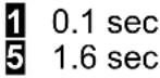 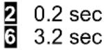 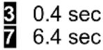 | |
| Triggering | [1840] |  |
| [1842] |  | |
| Trigger slope, Channel B | ||
| Decimal pt1 | [7080]  |  al point. al point. |
| Decimal pt2 | [7048] 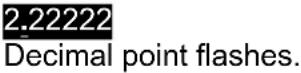 | Press to shift the decimal point. |
| Scale and Offset scaling method if selected under SEtuP | ||
| [R4ZD][R4C] | [1000] [1748] |  r r |
| [1000] [1710] | ||
 | ||
 | Select digit to flash. | r |
| Sc p p | ||
| [1000] | [1000] [1000] | [1000] |
| Scale and Offset scaling method if selected under SEtuP |
 | Press Menu |  | Press Digit Select Key |  | Press Value Select Key |
| Coordinates of 2 points scaling method if selected under SEtup | |||||
| Lo_In1Low signal input 1. | 0000000000000000000000000000000000000000000000000000000000000000000000000000000000000000000000000000 | Select -9 thru 9 for flashing first digit and 0 thru 9 for other flashing digits. Move decimal point location when flashing. | |||
| Lo_rd1Reading at Lo In1. | 00000000000000000000000000000000000000000000000000000000000000000000000000000000000000000000000 | Select -8 thru 9 for flashing first digit and 0 thru 9 for other flashing digits. Decimal point is fixed by dEC.Pt1. | |||
| Hi_In1High signal input 1. | 000000000000000000000000000000000000000000000000000000000000000000000000000000000 | Select -9 thru 9 for flashing first digit and 0 thru 9for other flashing digits. Move decimal point location when flashing. | |||
| Hi_rd1Reading at Hi In1. | 000000000000000000000000000000000000000000000000000000000000000 | Select -9 thru 9 for flashing first digit and 0 thru 9for other flashing digits. Decimal point is fixed by dEC.Pt1. | |||
| Lo_In2Low signal input 2. | 00000000000000000000000000000000000000000000000000000000 | Select -9 thru 9 for flashing first digit and 0 thru 9for other flashing digits. Move decimal point location when flashing. | |||
| Lo_rdReading at Lo In2. | 0000000000000000000000000000000000000000000000000000000000 | Select -9 thru 9 for flashing first digit and 0 thru 9for other flashing digits. Decimal point is fixed by dEC.Pt1. | |||
| Hi_In2High signal input 1. | 0000000000000000000000000000000000000000000000000 | Select -9 thru 9 for flashing first digit and 0 thru 9for other flashing digits. Move decimal point location when flashing. | |||
| Hi_rd2Reading at Hi In1. | 000000000000000000000000000000000000000000000000 | Select -9 thru 9 for flashing first digit and 0 thru 9for other flashing digits. Decimal point is fixed by dEC.Pt1. | |||
| Preset function. Displayed for Total modes A-b Ud or A_bU/d | |||||
| PrESEtPreset* | 000000000000000000000000000000000000000000Select digit to flash. | Select -9 thru 9 for flashing first digit and 0 thru 9for other flashing digits. dEC.Pt1 is used. Åhen the meter counts up and reaches the Preset, it reverts to Offset1. Åhen the meter counts down and reaches Offset1, it reverts to Preset. Set to 0 for no Preset. | |||
| Special curve offset for square root or custom curve linearization if selected under ConFiG | |||||
| rd0_In | 000000000000000000000000000000000Select digit to flash. | Select -9 thru 9 for flashing first digit and 0 thru 9for other flashing digits. Decimal point is fixed by dEC.Pt1. | |||
Coordinates of 2 points scaling method if selected under SEtuP
| Lo_In1Low signal input 1. | 000000 000000 0000000000000000000000000000000000000000000000000000000000000000000000000000000000000000000000000000 | Select -9 thru 9 for flashing first digit and 0 thru 9 for other flashing digits. Move decimal point location when flashing. |
| Lo_rd1Reading at Lo In1. | 000000 000000 0000000000000000000000000000000000000000000000000000000000000000000000000000000000 | Select -9 thru 9 for flashing first digit and 0 thru 9for other flashing digits. Decimal point is fixed by dEC.Pt1. |
| Hi_In1High signal input 1. | 000000 000000 0000000000000000000000000000000000000000000000000000000000000000000000000000000 | Select -9 thru 9 for flashing first digit and 0 thru 9for other flashing bits. Move decimal point location when flashing. |
| Hi_rd1Reading at Hi In1. | 000000 000000 000000000000000000000000000000000000000000000000000000000000000000000000000000000 | Select -9 thru 9 for flashing first digit and 0 thru 9forother flashing digits. Decimal point is fixed by dEC.Pt1. |
| Lo_In2Low signal input 2. | 000000 000000 00000000000000000000000000000000000000000000000000000000000000000000000000000000000 | Select -9 thru 9 for flashing first digit and 0 thru 3for other flashing bits. Move decimal point location when flashing. |
| Lo_rdReading at Lo In2. | 000000 000000 0000000000000000000000000000000000000000000000000000000000000000000000000000000000 | Decal point is fixed by dEC.Pt1. |
| Hi_In2High signal input 1. | 000000 000000 000000000000000000000000000000000000000000000000000000000000000000000000000 | Select -9 thru 9 for flashing first digit and 0 thru 9for other flashing bits. Move decimal points location when flashing. |
| Hi_rd2Reading at Hi In1. | 000000 000000 00000000000000000000000000000000000000000000000000000000000000000 | Select -9 thru 9 for flashing first digit and 0 thru 9for other flashing bits. Decimal point is fixed by dEC.Pt1. |
| Preset function. Displayed for Total modes A-b Ud or A_bU/d | ||
| PrESEtPreset* | 000000 000000 000000000000000000000000000000000Select digit to flash. | Select -9 thru 9 for flashing first digit and 0 thru 9for other flashing digits. dEC.Pt1 is used. Åhen the meter counts up and reaches the Preset, it reverts to Offset1. Åhen the meter counts down and reaches Offset1, it reverts to Preset. Set to 0 for no Preset. |
| Special curve offset for square root or custom curve linearization if selected under ConFiG | ||
| rdO_In | 000000 000000 00000000000000000000000000000Select digit to flash. | Select -9 thru 9 for flashing first digit and 0 thru 9for other flashing digits. Decimal point is fixed by dEC.Pt1. |
| Scale multiplier for combinations of two channels (e.g., AxB, A/B) if selected under InPut | ||
| rESoLnResolution | Flashing 6-digit number in decade steps from0.00001 to 100000 | Press ▲to select. This is a multiplier R to avoid overflow or underflow of arithmetic combinations of Channels A and B. |
| Quartz crystal time base calibration | ||
| CALib | Time base calibration. | Do not change. See Calibration section of manual. |
| Option dependent menu items | ||
| SourcE AL SET AL S34 dEUn1H dEUn2H dEUn1b dEUn2b dEUn3H DEUn4H DEUn3bDEUn4b Menu items related to alarm setup These will only appear if a relay board is detected. If so, please see Section 14. | ||
| An_SEt An_Lo An_Hi or An_SEt An_Lo1 An_Hi1 An_Lo2 An_Hi2 Menu items related to analog output. These will only appear if a single or dual analog output board is detected. If so, please see Section 15. | ||
| SEr_1 SEr_2 SEr_3 SEr_4 Menu items related to serial communications. These will only appear if an RS232 or RS485 I/O board is detected. If so, please see Section 16. | ||
| Menu lockout items | ||
| Loc_1 Loc_2 Loc_3 Loc_4 Menu items used to enable or lock out (hide) other menu items. Loc menu items may be locked out by a hardware jumper. Please see Section 9. | ||
* See Glossary for explanation of item.
11. PROCESS RECEIVER & TOTALIZER SIGNAL CONDITIONER
This signal conditioner board converts 0-1 mA, 4-20 mA or 0-10 V analog process signals to a frequency signal, which is then read by the counter main board and processed mathematically for display of rate, total (time x rate), time based on rate, or batch control.
The board needs to be configured via jumpers for the input signal range. The meter software recognizes the board and brings up the applicable menu items for it.
Please see further manual pages for the following features: relay output, analog output, serial communications, and transducer excitation output.
JUMPER SETTINGS

flowchart
graph TD
    A["Input Range"] --> B["Jumper Position A1"]
    B --> C["0-10V"]
    B --> D["0-1 mA"]
    B --> E["4-20 mA"]
    B --> F["None"]
    B --> G["a"]
    B --> H["b"]
    style A fill:#f9f,stroke:#333
    style B fill:#ccf,stroke:#333
    style C fill:#dfd,stroke:#333
    style D fill:#dfd,stroke:#333
    style E fill:#dfd,stroke:#333
    style F fill:#dfd,stroke:#333
    style G fill:#dfd,stroke:#333
    style H fill:#dfd,stroke:#333
OPERATING MODES
RATE FROM A 4-20 mA OUTPUT FLOW METER
| Dig. No. | S | 1 | 2 | 3 | 4 | 5 | 6 | ||||||
| InPut | U | F | 4 | - | 2 | 0 | A | O | n | L | y | ||
| SEtuP | 0 | 0 | 1 | 0 | |||||||||
| ConFiG | 1 | 0 | 0 | 0 | |||||||||
| dSPyno | 0 | 1 | |||||||||||
| GAtE t | 0 | 0 | 0. | 2 | 2 | ||||||||
| FiLtEr | 0 | 0 | 1 | 0 | 5 | ||||||||
| DecPt1 | 1 | 1 | 1. | 1 | 1 | 1 | |||||||
| Lo In1 | 0 | 4. | 0 | 0 | 0 | 0 | |||||||
| Lo rd1 | 0 | 0 | 0. | 0 | 0 | 0 | |||||||
| Hi In1 | 2 | 0. | 0 | 0 | 0 | 0 | |||||||
| Hi rd1 | 0 | 0 | 5. | 8 | 2 | 0 | |||||||
| CALib | - | 0 | 0 | 0 | 0 | 0 | Do Not Change Calib | ||||||
Application: Display rate in GPM to 3 decimal places from a 4-20 mA flow meter where 4 mA = 0 GPM and 20 mA = 5.820 GPM.
Solution: Set Input to "VF420 A only." Under Setup, select the coordinates of 2 points scaling method. Under Config, select a display of 999999 and filtering. Set the decimal point to 3 places. For scaling, set Hi In1 to 20.0000 and Hi Rd1 to 5.820. Set Gate Time to 0.22 sec, which will provide noise averaging at a display update rate of 4/sec. Also set a 1.6 sec adaptive moving average filter to process the equivalent of 6 readings.
RATE MODE (Basic Counter)
Rate A accepts 0-1 mA, 4-20 mA or 0-10 V analog process signals for a process display scaled to engineering units. Scaling is normally done using the coordinates of 2 points method, where low and high input signals and the corresponding desired low and high displayed values are entered. Scaling can also be done by entering scale and offset directly. Āith Scale1 set to 1 and Offset1 set to 0, the full analog input range is displayed as 0-100000. Measurements are averaged over a gate time, which is programmable from 10 ms to 199.99 sec. Selecting a long gate time provides a slower display update rate but superior
noise filtering. Moving average filtering is also available. Square root extraction is selectable for use with differential pressure flow transducers. Custom curve linearization is available with the Extended counter.
RATE & TOTAL MODE (Basic Counter)
TOTAL FROM A 4-20 mA OUTPUT FLOW METER
Application: Display Total from a 4-20 mA flow meter where 4 mA = 0 and 20 mA = 5.820 GPM.
| Dig. No. | S | 1 | 2 | 3 | 4 | 5 | 6 | ||||||
| InPut | U | F | 4 | - | 2 | 0 | A | A | t | o | t | ||
| SEtuP | 0 | 0 | 1 | 0 | |||||||||
| ConFiG | 1 | 1 | 0 | 0 | |||||||||
| dSPyno | 0 | 1 | |||||||||||
| CutoFF | 0 | 0. | 0 | 1 | 0 | ||||||||
| GAtE t | 0 | 0 | 0. | 1 | 0 | ||||||||
| FiLtEr | 0 | 0 | 1 | 0 | 3 | ||||||||
| DecPt1 | 1 | 1 | 1. | 1 | 1 | 1 | |||||||
| DecPt2 | 2 | 2 | 2 | 2. | 2 | 2 | |||||||
| Lo In1 | 0 | 4. | 0 | 0 | 0 | 0 | |||||||
| Lor d1 | 0 | 0 | 0. | 0 | 0 | 0 | |||||||
| Hi In1 | 2 | 0. | 0 | 0 | 0 | 0 | |||||||
| Hir d1 | 0 | 0 | 5. | 8 | 2 | 0 | |||||||
| SCALE2 | 1. | 6 | 6 | 6 | 6 | 7 | 0. | 0 | 0 | 1 | |||
| OFFSt2 | 0 | 0 | 0 | 0. | 0 | 0 | Do Not Change Calib | ||||||
| CALib | - | 0 | 0 | 0 | 0 | 0 | |||||||
Solution: Set Input to "VF420 A A Total, which displays Rate as Item #1 & Total a Item #2. Under dSPyno, select Item #2 to be displayed after meter reset. Set Gate Time to 0.1 sec to provide fast display updates with noise averaging. Set DecPt1 to 3 places for Rate and DecPt2 to 2 places for Total. Under Setup, select the coordinates of 2 points scaling method for Rate. Set Hi In1 to 20.0000 and Hi Rd1 to 5.820. You will need to use scale & offset to scale Total. Ente 1.66667 for Scale2 and a multiplier of 0.001. That is because totalizing sums rate readings every second. Since our rate is in units per minute, we have to divide by 60, the multiply by 0.1 for two decimal places. You may also enter a Cutoff such as 0.010 GPM, below which zero offset errors and negative values will not be totalized.
Rate A, Total A allows rate to be displayed as Item #1 and total as Item #2. Scale2 and Offset2 apply to total. Total is calculated as the product of displayed rate and time in seconds. Since rate may be displayed in units per second, units per minute, units per hour or other units, the total must be scaled appropriately. If rate is in units per minute, multiply the total by 1/60. This is achieved by setting Scale2 to a scale factor of 1.66666 and a multiplier of 0.01. If rate is in units per hour, multiply the total by 1/3600. This is achieved by setting Scale2 to a scale factor of 2.77778 and a multiplier of 0.0001. If square root extraction or custom curve linearization (available with Extended counter) have been selected, totalizing will be of the linearized rate readings.
BATCH CONTROL MODE (\_bAtCH) (Extended Counter)
Batch control uses the meter with a dual relay controller board to control repetitive fill operations. Relay #1 (or Setpoint #1) is used as the batch relay. Relay #2 (or Setpoint #2) can be assigned to another limit, such as pre-warn to slow filling near the setpoint, end-of-process, or rate alarm.
- In batch control mode the meter displaying “Ready”, the meter waits until the RESET key is pushed, it then energizes Relay #1 and displays the changing Batch Total starting at “Offset2”. Âhen the setpoint 1 value is reached, Relay #1 de-energizes for the duration of the “time out” setting. Relay #1 then re-energizes, the Batch Total resets, and the fill cycle repeats.
- In batch control mode with “external gate”, the meter waits a the end of every cycle until an external gate input is grounded for a minimum of 3.33 ms. This starts a new fill cycle by energizing Relay #1 and resetting the Batch Total. Gate time is not used.
Three values are tracked and can be separately displayed by pressing the RESET key: Item #1, the Batch Total; Item #2, the Grand Total of all batches or Number of Batches (selectable during setup); and Item #3, the Fill Rate.
- Item #1, Batch Total, is the total of input pulses for that batch. It may be configured to count up from 0 to a preset, or to count down from a preset to 0. The preset value is placed in ALARM1. SCALE1 is positive whether counting up or down.
- Item #2, Grand Total, is the sum of previous Batch Totals and the current Batch Total. It can overflow to exponential format.
- Item #2 (alternate), Number of Batches, is the current count of batches. SCALE1 does not apply. dECPt1 is set to 1.
- Item #3, Fill Rate, is calculated with a fixed 20 ms gate time. It may be displayed as Item #3.
BATCH CONTROL WITH A 4-20 mA OUTPUT FLOW METER
| Dig. No. | S | 1 | 2 | 3 | 4 | 5 | 6 | ||||||
| InPut | r | A | t | E | b | A | t | C | H | ||||
| SEtuP | 1 | 0 | 0 | 1 | 0 | ||||||||
| ConFiG | 1 | 1 | 0 | 0 | |||||||||
| dSPyno | 0 | 1 | |||||||||||
| CutoFF | 0 | 0 | 0 | 0 | 0. | ||||||||
| GAtE t | 0 | 2 | 0. | 0 | 0 | ||||||||
| bAtCH | 1 | 0 | 0 | 1 | 0 | ||||||||
| FiLtEr | 0 | 0 | 1 | 0 | 5 | ||||||||
| SLOPE | 0 | 0 | |||||||||||
| DecPt1 | 1 | 1 | 1 | 1. | 1 | 1 | |||||||
| DecPt2 | 2 | 2 | 2 | 2. | 2 | 2 | |||||||
| SCALE1 | 1. | 6 | 6 | 6 | 6 | 7 | 0. | 0 | 1 | ||||
| OFFSt1 | 0 | 0 | 5 | 5. | 0 | 0 | |||||||
| Lo In2 | 0 | 4. | 0 | 0 | 0 | 0 | |||||||
| Lor d2 | 0 | 0 | 0 | 0. | 0 | 0 | |||||||
| Hi In2 | 2 | 0. | 0 | 0 | 0 | 0 | |||||||
| Hir d2 | 0 | 0 | 3 | 9. | 2 | 0 | |||||||
| rESoLn | 1 | ||||||||||||
| Source | 1 | 1 | |||||||||||
| AL SEt | 0 | 0 | 2 | 4 | 0 | ||||||||
| dEUn1b | 0 | 0 | 0 | 0. | 0 | 0 | |||||||
| dEUn2b | 0 | 0 | 0 | 0. | 0 | 0 | |||||||
| CALib | 0 | 0 | 0 | 0 | 0 | ||||||||
Application: Fill 55 gallon tanks. Use a 4-20 mA flow meter where 4 m A = 0 and 20 mA = 39.20 GPM. Slow down filling at 54 gallons. Cycle batches automatically with 20 sec between cycles. Display batch total & fill rate to 2 places. Also track number of batches.
Solution: Use an Extended counter with a dual relay output board. Set Input to "Rate Batch." Set Batch to count up to ALARM1, to use Gate Time as delay between batches and to make Item #2 the number of batches. Set Gate Time to 20 sec. Set DecPt1 and DecPt 2 to two decimal places for Items #1 and #3 (Batch Total and Rate). Scale Item #3 (Rate) using the coordinates of 2 points method so that 20.0000 mA will be displayed as 39.20 GPM. Scale Item #1 (Batch Total) by entering a Scale1 of 1.66667 and a multiplier of 0.01. That is because totalizing sums readings in gallons every second. Since our rate is in GPM, we have to divide by 60. Enter an Offset1 of 55.00to serve as the batch setpoint in gallons. Set Setpoint to 54.00 to activate Relay 2 to slow the rate.
KEYSTROKES FOR SETUP
If the MENU key does not work, see Section 9 "Enabling & Locking Out Menu Items." Menus are dynamic. Menu items will only appear if appropriate for previously made menu selections. For example, Batch menu items will only appear if "Batch" was selected under "Rate." Extended counter items will only appear if "Extended" was selected under "Config."
| MENU→Press Menu | PEAK▶Press Digit Select Key | RESET▲Press Value Select Key | |
| Input | VF0-100-10V full-scale inputVF4-204-20 mA full-scale inputVF_0-10-1 mA full-scale input | Basic | A_OnLy Rate for Channel A (Item #1). |
| A_Atot Rate for Channel A (Item #1). Total for Channel A (Item #2). | |||
| Extended | bAtCH Batch control mode. Batch total (Item #1). Grand total or number of batches (Item #2). Fill rate (Item #3). | ||
| 1/A 1/Rate for Channel A (Item #1). | |||
| SETuP Setup | 000_0Stored totals | 0 Zero totals at power-on.1 Restore totals at power-on. | |
| Leading zeros | 0 Blank leading zeros.1 Display leading zeros. | ||
| Scale factor 1 setup | 0 Input scale factor 1 and offset 1.1 Use coordinates of 2 points method. | ||
| Operation of rear connector inputs 1 & 2.True = logic 1 (0V or tied to digital ground).False = 0 (5V or open). | 0 1 = Meter Reset*, 2 = Function Reset*1 1 = Meter Reset*, 2 = Meter Hold*2 1 = Meter Reset*, 2 = Peak or Valley Display*3 1 = Meter Reset*, 2 = External Gate*4 1 = Function Reset*, 2 = Meter Hold*5 1 = Valley Only Display**, 2=Peak Only Display**6 1 = Function Reset*, 2 = External Gate*7 1 = Meter Hold**, Peak or Valley Display**8 1 = Reset Total A**, 2 = Reset Total B**9 1 = Force Alarm1, 2 = Force Alarm2A 1 = Meter Reset*, 2 = Display Blank*1 = Function Reset*, 2 = Display Blank*2 C 1 = Meter Hold*, 2 = Display Blank*3 D 1 = Peak or Valley Display**, 2 = Display Blank**4 E 1 = Display Blank, 2 = External Gate*5 F 1 = Display Item #2, 2 = Display Item #3Aith 1 and 2 at 5V or open, Display Item #1.----* 1 & 2 both at 0V = Meter Reset (can restore totals).** 1 & 2 both at 0V for selections 5, 7, 3, D = Function Reset* (erases all totals). | ||
| Press Menu |  Press Digit Select Key Press Digit Select Key |  Press Value Select Key Press Value Select Key | |
  | [X   |              | |
  |     | ||
  |   | ||
  |   | ||
 Display # Display # | [2670][TBVX] | [444H][DD4S][CEFS] | |
| [829H][244H]Meter Reset* | [5X3C]  | ||
| [WXA1]Totalizing cutoff* |  00000 00000[22X1][44X1] 00000 00000[22X1][44X1] |  | |
| [1750]Gate time* | [3703] 000.00 000.00[573C][3613] | - - [0220] [8W950] [8W950] | |
| [6108]Timeout* | [15747] 000.00 000.00[9C27][2646] | [220V][AZX1][X86A] | |
 | Press Menu |  | Press Digit Select Key |  | Press Value Select Key |
 Batch setup Batch setup |  & &  | 0.000 | Not used with VF Batch. Set to 0. | ||
| 10000 | 0.000 | Use gate time* as delay between batches.Use External Input B to start each new batch. | |||
| 10000 | 0.000 | Make Item #2 the Grand Total of all batches.Make Item #2 the Total Number of batches. | |||
 | 0.000 | Display "rEAdy." RESET key starts batching.Start batching upon Meter Reset. | |||
| FiLtEr Filtering | 0.0000 | 0.000 | Adaptive moving average filter. Restarts filter for high actual changes in signal.Conventional moving average filter without reset. | ||
| 0.0000 | 0.000 | Peak* or Valley* value from unfiltered signal.Peak* or Valley* value from filtered signal. | |||
| 0.0000 | 0.000 | Display value of unfiltered signal.Display value of filtered signal. | |||
| 0.0000 | 0.000 | Set adaptive filter for normal noise.Set adaptive filter for presence of high transients. | |||
 | 0.000 | No filter 1 0.1 sec 2 0.2 sec 3 0.4 sec0.8 sec 5 1.6 sec 6 3.2 sec 7 6.4 sec | |||
| dEC.Pt1 Decimal pt1 | 10000 | 0.000 | 11111 11.1111 111.111 1111.11 11111.1 111111.press ▲to shift the decimal point. | ||
| dEC.Pt2 Decimal pt2 | 20000 | 0.000 | 22222 22.2222 222.222 2222.22 22222.2 222222.press ▲to shift the decimal point. | ||
| Scale and Offs ing method if select under SEtuP | |||||
| SCALE1 Scale Factor 1 | 0.0000 0.00000 0.000000.000000 0.000000 0.000000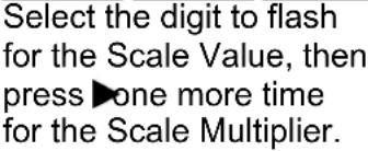 | 0.000 | select -9 thru 9 for flashing first digit and 0 thru 9 for other flashing digits. This will set the Scale Value*from -9.99999 to 9.99999 with a fixed decimal point.Then press ▲to select a value from 00001 to 100000 in decade steps for the Scale Multiplier.Scale Factor = Scale Value x Scale Multiplier. | ||
| OFFSt1 Offset 1 | 0.0000 000000 0000000.000000 0000000HHDY | 0.000 | select -9 thru 9 for flashing first digit and 0 thru 9 for other flashing digits. Use dEC.Pt1 to set the decimal point. | ||
| SCALE2 Scale Factor 2. Make the sa | 0.000 | Scale Factor 1. | |||
| OFFSt2 | 0.000 | 0.000 | make the same as for Offset 1. | ||
 Press Menu Press Menu |  Press Digit Select Key Press Digit Select Key |  Press Value Select Key Press Value Select Key |
 | ||
 Low signal input 1. Low signal input 1. |    | Select9thru9for flashing first digit and0thru9for other flashing digits. Move decimal point location when flashing. |
 Reading at Lo In1. Reading at Lo In1. |    | Select9thru9for flashing first digit and0thru9for other flashing digits. Decimal point is fixed bydEC.Pt1. |
 High signal input 2. High signal input 2. |    | Select9thru9for flashing first digit and0thru9for other flashing digits. Move decimal point location when flashing. |
 Reading at Hi In2. Reading at Hi In2. |    | Select9thru9for flashing first digit and0thru9for other flashing digits. Decimal point is fixed bydEC.Pt1. |
 | ||
 |    | Select9thru9for flashing first digit and0thru9for other flashing digits. Decimal point is fixed bydEC.Pt1. |
 | ||
 Resolution Resolution |    | Press▲to select. This multiplierRappears with the Batch mode and can be applied to Grand Total to set its decimal point. |
 | ||
 |  | Do not change. See Calibration section of manual. |
Option depen  | ||
  | ||
  | ||
  | ||
 | ||
  | ||
12. QUADRATURE SIGNAL CONDITIONER

Our quadrature signal conditioner board can be used for quadrature position (with Basic or Extended main board) or for quadrature rate (with Extended main board). Two quadrature signals, which are 90° out of phase, are applied to the Channel A and B inputs. Their phase relationship determines whether the count is up (+) or down (-). A zero index signal may be applied to Channel Z as a position reference.
Position in engineering units is determined by adding or subtracting transitions, as determined by the signal phase relationship, applying a programmable scale factor to the total, and adding programmable OFFSET1 to the scaled total. The display update rate is set by a gate time, which is programmed to 10 ms. Āhen the scaled total reaches a programmable Preset, it is reset to OFFSET1.
Rate in engineering units is determined by measuring Rate A and Rate B in transitions per second for Channels A and B, subtracting Rate B from Rate A, and applying a scale factor. Rate is measured over a gate time, which is programmable from 10 ms to 199.99 sec. Since one of the two channels may not be measuring any pulses over the gate time, a timeout from 10 ms to 199.99 sec is also programmable. The meter update rate will never be less than every timeout. Quadrature rate provides a high resolution, high accuracy display.
A zero index function is available on a separate zero index channel to reset the count to the expected count when a zero index pulse is detected. For example, if 3000 counts is expected after three 1000-count revolutions but the current count is 2998 when the zero index pulse is detected, the count is reset to 3000. Since a wide zero index pulse could cause a count discrepancy in the region between transitions, the zero index pulse can be shaped by an AND combination with the A or B channels, as set by jumpers. Please see the diagram at the top of this page, which shows an AND combination of the zero index channel, Channel A and Channel B.
To zero the counts at a hard stop, use function reset.
Please see further manual pages for the following features: relay output, analog output, serial communications, and transducer excitation output.
Jumper Settings

flowchart
graph TD
    A["Block E9"] --> B["a"]
    B --> C["b"]
    C --> D["c"]
    D --> E["E8"]
    E --> F["a"]
    F --> G["b"]
    G --> H["e10"]
    H --> I["c"]
    I --> J["b"]
    J --> K["E6"]
    K --> L["a"]
    L --> M["b"]
    M --> N["e5"]
    N --> O["d"]
    O --> P["E4"]
    P --> Q["a"]
    Q --> R["b"]
    R --> S["e3"]
    S --> T["a"]
    T --> U["b"]
    U --> V["E2"]
    V --> W["a"]
    W --> X["b"]
    X --> Y["c"]
    Y --> Z["E1"]
Note: Letters indicate jumper position. Jumpers are installed on pins adjacent to letters.
| Input Type E2 E4 E6 E5 | ||||||
| Single-ended (signal & return)DifferentialDifferential (with excitation and no zero index) | a, cbb | a, cbb | a, cbb- | ccb, d | ||
| Input Termination (for differential inputs only) E1 | E3 E5 | |||||
| For long cable runsFor short cable runs | anone | anone | anone | |||
| Phase for Up Count E7 | ||||||
| A positive, negative B transition (A leads B)A positive, positive B transition (B leads A) | nonea | |||||
| Count-by Options E9 | ||||||
| X1 = positive edge of A inputX2 = positive & negative edges of A inputX4 = positive & negative edges of A & B inputs | noneab | |||||
| Zero Index Polarity E8 | ||||||
| PositiveNegative | cnone | |||||
| Zero Index ANDing E10 E8 | ||||||
| Zero Index (no ANDing)Zero Index AND /AZero Index AND /BZero Index AND AZero Index AND BZero Index AND /A AND /BZero Index AND /A AND BZero Index AND A AND /BZero Index AND A AND B | caaaabb | ---aba,b---aba,b | ||||
The quadrature decoder board generates up (+) and down (-) counts that are arithmetically totalized on the main counter board and are then displayed. The decoder board has input circuitry that may be jumpered for single-ended input signals or balanced line driver signals. It accepts normal A & B quadrature signals and, if present, a zero index signal. The A & B signals are 90° out of phase, and their phase relationship determine whether Up counts are added to the total, or Down counts are subtracted from the total.
Since incremental optical encoders may have a different A & B phase relationship to indicate up and down counting, the board has a jumper E7 (BPOL) on the B signal to allow selection of the desired phase. Āith the jumper not installed, Up output pulses are created when the B signal has a positive transition while the A signal is at a positive level (A leads B). Āith the jumper installed, Up output pulses are created when the B signal has a negative transition while the A signal is at a positive level (B leads A). Āith the opposite phase shown, the effect of E7 reverses.

Āith E7 open, counts up.
Āith E7 jumpered, counts down
The board has jumpers that allow counting by 1, 2 or 4 counts per cycle of the A or B signals. The edges that are counted are:
X1 = positive transitions of the A signal.
X2 = positive and negative transitions of the A signal.
X4 = positive and negative transitions of both the A and the B signals.
Digital filtering is provided for the A & B signals to reduce the probability of noise providing false counts.
Some optical encoders create a zero index signal once per revolution that indicates when the encoding wheel is at its zero position. Each time this signal is created, the total count should be a multiple of the number of counts per revolution of the coding wheel. If this feature is enabled in the counter, the counter checks to see if total counts are an exact multiple of the counts per revolution. If so, it does nothing, and if not, it changes the total to the closest exact multiple. The counts per revolution are entered into the counter via the menu item Pulses. From 0 to 59,999 pulses may be entered. If X2 or X4 counting is enabled on the board, the value entered into Pulses should be the counts (or pulses) per revolution of the encoder multiplied by this factor of X2 or X4. If Scale is a factor other than 1, include it as a multiplying factor when determining the value of Pulses to enter. Do not include the value of OFFSET1.
Example:
If the encoder produces 256 cycles per revolution, X2 counting is selected by a jumper on the board and from the front panel Menu of the counter, SCALE1 is set to 3, and OFFSET1 is set to 100, then set PULSES = 256 x 2 x 3 = 1536 from the front panel menu.
The zero index channel has the same digital filtering as the A & B channels. It contains a Polarity jumper that allows selection of either a positive or negative zero index signal. It also contains two Control inputs, C1 and C2 that control the ANDing of the zero index signal with the Channel A and Channel B signals. See “Zero Index Setup” below.
The Item indicator light (center right) may be used to determine the location of the Zero Index. This indicator is lighted while the zero index signal is being received. The zero index signal must be jumpered for the correct polarity. If, during encoder motion, the indicator is on more than it is off, it is likely that the zero index signal is jumpered for the wrong polarity. If so, add a Polarity jumper to switch E8, position C. If it already has a jumper, remove it.
From the menu, a value may be entered for Offset1. As explained below under "Mechanical Zero", OFFSET1 allows a mechanical zero position different from the zero index position. The displayed value is the sum of the following:
- The total bidirectional counts from the optical encoder since the last counter reset or function reset.
- The correction factor from the last zero index correction calculation.
- OFFSET1
Example:
Suppose that the encoder contains 30 pulses per revolution and that X1 counting is used. Further suppose that when the mechanics are at their 0 position, the zero index is at 10, OFFSET 1 = 10, and the counter is reset when the encoder is at the 5 position.
| Reset | |||||||
| v | |||||||
| Position 0 5 10 20 30 Index | 40 | 50 | |||||
| ^ | ^ | ||||||
| Internal Total → | 0 | 5 | 15 | 25 | 35 | 45 | |
| Correction | 0 | -5 | -5 | -5 | -5 | -5 | |
| OFFSET | 10 | 10 | 10 | 10 | 10 | 10 | |
| ---- | ---- | ---- | ---- | ---- | ---- | ||
| Display | 10 | 10 | 20 | 30 | 40 | 50 | |
| Internal Total ← | -5 | 0 | 5 | 15 | 25 | 35 | 45 |
| Correction | -5 | -5 | -5 | -5 | -5 | -5 | -5 |
| OFFSET | 10 | 10 | 10 | 10 | 10 | 10 | 10 |
| ---- | ---- | ---- | ---- | ---- | ---- | ---- | |
| Display | 0 5 | 10 20 | 30 40 | 50 | |||
Once the index point has been passed, the display matches the position. Prior to that, the display is in error.
Ahen the counter is displaying Quadrature Total and the Total is reset using the Reset & Peak buttons (Function Reset), the internal Total is set to zero, but the zero index correction is not affected. This results in a display of the correction value plus OFFSET1. To zero the internal Total and the correction value, the counter must be reset using the Reset & Menu buttons (Meter Reset). This results in a display of OFFSET1.
ZERO INDEX SETUP
The relationship between the zero index correction signal and the Channel A & B signals varies by encoder model and by manufacturer. To accommodate this variation, the Quadra-ture board has control jumpers and selectable outputs that provide ANDing of the zero index signal with all possible combinations of the Channel A & B signals.
Consider a typical encoder model that produces the waveforms shown below. Assume that X4 counting is selected. The count increases or decreases with each A & B transition and remains steady between transitions. The counts shown below the waveforms represent the effect of the zero index correction ZI if no ANDing is used. Note the difference in count in the regions between transitions when counting up and then counting down. The zero index correction is made on the leading edge transition of the zero index signal. Åhen counting down, the leading edge is the trailing edge of the signal shown below because time is increasing from right to left.
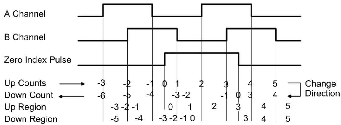
other
| Channel | Up Counts | Down Count | |---------|-----------|------------| | A | -3 | -6 | | B | -2 | -5 | | B | -1 | -4 | | B | 0 | -3 | | B | 1 | -2 | | B | 2 | -1 | | B | 3 | 0 | | B | 4 | 1 | | B | 5 | 2 | | B | 4 | 3 | | B | 3 | 4 | | B | 2 | 5 | | B | 1 | 4 | | B | 0 | 3 | | B | -1 | 2 | | B | -2 | 1 | | B | -3 | 0 | | B | -4 | -1 | | B | -5 | -2 | | B | -6 | -3 | | B | -7 | -4 | | Zero Index Pulse | -3 | -6 | | Zero Index Pulse | -2 | -5 | | Zero Index Pulse | -1 | -4 | | Zero Index Pulse | 0 | -3 | | Zero Index Pulse | 1 | -2 | | Zero Index Pulse | 2 | -1 | | Zero Index Pulse | 3 | 0 | | Zero Index Pulse | 4 | 1 | | Zero Index Pulse | 5 | 2 | | Zero Index Pulse | 4 | 3 | | Zero Index Pulse | 3 | 4 | | Zero Index Pulse | 2 | 5 | | Zero Index Pulse | 1 | 4 | | Zero Index Pulse | 0 | 3 | | Zero Index Pulse | -1 | 2 | | Zero Index Pulse | -2 | 1 | | Zero Index Pulse | -3 | 0 | | Zero Index Pulse | -4 | -1 | | Zero Index Pulse | -5 | -2 | | Zero Index Pulse | -6 | -3 | | Zero Index Pulse | -7 | -4 | | Zero Index Pulse | -8 | -5 | Change Direction: Up Counts; Down Count; Up Region; Down Region; Change Direction: Change DirectionIt follows that a wide zero index signal causes a discrepancy in the count in the regions between transitions when counting up and counting down. To correct this situation, AND the zero index signal with the A & B channel signals. Assume for this example the zero index is ANDed with the inverse of A (/A) and the inverse of B (/B) to produce ZIY as shown below.

other
| Signal | Up Counts | Down Count | |--------|-----------|------------| | A Channel | -3 | -4 | | B Channel | -2 | -3 | | ZIY | -1 | -2 | | Zero Index AND ZIY = ZIR | 0 | -1 | | ZIR | 1 | 0 | | Change Direction | 2 | 1 | | Up Region | -3 | -2 | | Down Region | -2 | -1 | | ZIY | 0 | 0 | | Change Direction | 2 | 3 | | Up Region | 1 | 2 | | Down Region | 2 | 3 | | ZIY | 3 | 4 |By ANDing the zero index signal with the A & B channels, there is no regional discrepancy between counting up and counting down.
There are 2 control signals, C1 and C2, and 3 outputs, ZI, ZIX and ZIY. These may be jumpered to provide 8 selections of ANDed signals or the zero index signal without ANDing.
| Zero Index Polarity | Jumper Position |
| E8 | |
| Positive | None |
| Negative | c |
| Zero Index ANDing | Jumper Position | |
| E10 E8 | ||
| Zero Index (no ANDing) | C | - |
| Zero Index AND /A | a | - |
| Zero Index AND /B | a | a |
| Zero Index AND A | a | b |
| Zero Index AND B | a | a, b |
| Zero Index AND /A AND /B | b | - |
| Zero Index AND /A AND B | b | a |
| Zero Index AND A AND /B | b | b |
| Zero Index AND A AND B | b | a, b |
The manufacture's data sheet for the optical encoder will show the position and width of the zero index signal with respect to the A channel and B channel signals. Selection of one of the above combinations depends on that relationship and the polarity of the channel A & B signals when the mechanical position is zero. Be sure to take into account the selected phase relationship determined by the presence of or absence of jumper E7-a (BPOL). Jumper E7-a is selected to cause the display to count in the proper direction. If jumper E7 is in place, the channel B signal will have the opposite polarity from the channel B output of the encoder.
MECHANICAL ZERO
By using the Counter's OFFSET1 value, it is possible to place the mechanical zero (zero counter reading) at some point other than the location of the zero index. The following technique describes how to accomplish this.
- Set the E8 & E10 jumpers as described above to produce the desired Zero Index signal.
- Set OFFSET1 = 0.
- Reset the counter (counter reset).
- Rotate the optical encoder in the positive direction until the reading jumps to zero at the zero index point (Item indicator lights).
- Reverse the direction of rotation until the desired zero mechanical position is reached.
- Note the reading and enter that reading into OFFSET1 using the opposite polarity of the display.
-
Reset the counter, and it will display the OFFSET1 value because the internal total counter = 0 and the correction = 0. The position of the encoder when the counter is reset is not critical.
-
Rotate the optical encoder past the zero index point to set the internal correction.
- Return to the desired zero mechanical position and verify a zero reading.
This completes the procedure. If the encoder is rotated back to mechanical zero, it should read zero. Note: Any time the counter is powered up or reset, the optical encoder should be rotated past the zero index point one time to set the internal correction
If a zero index signal is not available from the encoder, perform the following procedure:
- Remove any E10 jumpers to eliminate the Zero Index signal.
- Set OFFSET1 = 0.
- Adjust the optical encoder to the mechanical zero position and with it in this position, reset the counter.
SETUP SUMMARY
- Set the input signal jumpers.
A. For single-ended signals such as TTL or CMOS, use jumpers c of E2, E4 and E6 and jumper a of E6. Input signals are applied as follows:
Channel A, P5-1X (AH)
Channel B, P5-3Y (BH)
If an excitation voltage is required, use jumper a of E2 and jumper a of E4.
B. For differential line driver or balanced input signals, use jumper b for E2, E4 and E6. If 120 ohm line termination resistors are desired, place jumpers E1, E3 and E5.
2. Set the correct counting direction by placing or omitting the Channel B polarity jumper E7.
3. Choose X1, X2 or X4 counting and omit a and b of E9 for X1, place a of E9 for X2 or place b of E9 for X4. Determine the scale factor to be used by the counter and set SCALE1 to this value using the counter Menu. Most often it will be set to 1.00000 with a multiplier of 1.
4. If the Zero Index is to be used, do the following:
A. Temporarily place jumper c of E10 and rotate the encoder while watching the Item indicator of the display. If it is OFF most of the time, the Z polarity is correct. If it is ON most of the time, the Z polarity is incorrect, so add jumper c of E8 if it is missing, or remove jumper c of E8 if it is in place.
B. From the manufacturer's specifications for the encoder showing the relationship of the Zero Index signal to the Channel A and Channel B signals, determine from the table above the desired positions of jumpers a and b of E8 and a, b or c of E10. If not used here, remove jumper c of E10 that was placed for the test in A. above.
C. From the manufacture's specifications for the encoder, determine the number of cycles per revolution. Multiply this by 1, 2, or 4 depending on the selection of X1, X2 or X4 counting and multiply that result by the counter scale factor. Put the final result in the counter Menu item, PULSES.
- Follow the procedure outlined above under the heading MECHANICAL ZERO.
WAVESHAPE EXAMPLES BY ENCODER MANUFACTURER
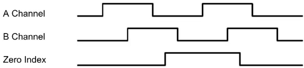
Allen Bradley: current sink, open collector & line driver, CCÃ rotation

Allen Bradley: current source, CCÃ rotation.

BEI: Models H25, L25, E25, MOD5500, MOD5600, CCÃ rotation.
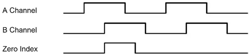
BEI: Models MX-51, MX-21, CCÃ rotation.

BEI: Models E20, E11, E15, CMX216, MOD900, CÃ rotation.

Bourns: EN Series.

Computer Optical Products
Models CP-350, CP-360, CP-370, CP-850, CP870, CC rotation.

Encoder Prod: Models H25, L25, E25, MOD5500, MOD5600, CCÃ rotation

Grayhill & Oak-Grigsby: CÃ rotation. No Zero Index.
QUADRATURE RATE
Rate and direction may also be displayed using an extended version of the counter. Using quadrature to determine rate not only has the advantage of displaying direction but also eliminates errors due to vibration and jitter that cause erroneous readings in standard rate meters. The meter uses A-B to display quadrature rate. Scale 1 is used to set A to the proper value and scale 2 is set to identical values. Rate (I1) is the difference between Channel A and Channel B.
PROGRAMMING EXAMPLE FOR QUADRATURE TOTAL: DISPLAY DISTANCE TO 0.001 FT FROM A 1024 PULSE/REV QUADRATURE ENCODER
| Dig. No. | S | 1 | 2 | 3 | 4 | 5 | 6 | ||||||
| InPut | q | u | A | d | r | t | o | t | A | L | |||
| SEtuP | 0 | 0 | 1 | 0 | 0 | ||||||||
| ConFiG | 1 | 0 | 0 | 0 | |||||||||
| dSPyno | 0 | 1 | |||||||||||
| PULSES | 0 | 1 | 0 | 2 | 4. | ||||||||
| GAtE t | 0 | 0 | 0. | 1 | 0 | ||||||||
| DecPt1 | 1 | 1 | 1. | 1 | 1 | 1 | |||||||
| Lo In1 | 0 | 0 | 0 | 0 | 0 | 0 | |||||||
| Lo rd1 | 0 | 0 | 0. | 0 | 0 | 0 | |||||||
| Hi In1 | 0 | 1 | 0 | 2 | 4. | 0 | |||||||
| Hi rd1 | 0 | 0 | 1. | 7 | 8 | 2 | |||||||
| CALib | - | 0 | 0 | 0 | 0 | 0 | Do Not Change Calib | ||||||
Application: Display distance in feet with 3 decimal points using a 1024 pulse/revolution quadrature encoder tied to a roller with 1.782 ft circumference.
Solution: Set Input to "Quadrature Total." Set Gate Time to 0.01 sec for fast display updates. Set DecPt1 to 3 places. Under Setup, select coordinates of 2 points scaling method. Set Hi In1 to 1024.0 (pulses) and the desired Hi Rd1 to 1.782 (feet).
KEYSTROKES FOR SETUP OF QUADRATURE TOTAL
If the MENU Key does not work, see Section 9 "Enabling & Locking Out Menu Items."
| MENU→Press Menu | PEAK▶Press Digit Select Key | RESET▲Press Value Select Key | |
| InPut Input | quAdrQuadrature | Basic meter | totALQuadrature total (select for position) |
| Extended | rAtE_Quadrature rate. | ||
| SEtUP Setup | 00000Stored totals | 0Zero all totals at power-on1Restore totals at power-on. SetPULSESto 0. | |
| 00000Leading zeros | 0Blank leading zeros.1Display leading zeros. | ||
| 00000Scaling method | 0Input scale factor 1 and offset 11Use coordinates of 2 points method | ||
| 00000Not applicable | 0Set to 0. | ||
| 00000Operation of rear connector inputs 1 & 2.True = logic 1 (0V or tied to digital ground).False = 0 (5V or open). | 01 = Meter Reset*, 2 = Function Reset*1 = Meter Reset*, 2 = Meter Hold*21 = Meter Reset*, 2 = Peak or Valley Display*31 = Meter Reset*, 2 = External Gate*41 = Function Reset*, 2 = Meter Hold*51 = Valley Only Display**, 2=Peak Only Display**61 = Function Reset*, 2 = External Gate*71 = Meter Hold**, Peak or Valley Display**81 = Reset Total A**, 2 = Reset Total B**91 = Force Alarm1, 2 = Force Alarm2A1 = Meter Reset*, 2 = Display Blank*B1 = Function Reset*, 2 = Display Blank*C1 = Meter Hold*, 2 = Display Blank*D1 = Peak or Valley Display**, 2 = Display Blank** | ||
| E 1 = Display Blank, 2 = External Gate*F 1 = Display Item #2, 2 = Display Item #3Aith 1 and 2 at 5V or open, Display Item #1.----* 1 & 2 both at 0V = Meter Reset (can restore totals).** 1 & 2 both at 0V for selections5,7,3,D=Function Reset* (erases all totals). | |||
| ConFiCConfigura-tion | 0000 Display mode | 0 Normal, overload to exponential format1 Normal, overload to 999999Normally select 1, required for Preset function. See dual signal conditioner for other available modes. | |
| 0000 Counter type | 0 Basic counter (use for quadrature total)1 Extended counter | ||
| 0000 Square root | 0 Set to 0. | ||
| 0000 V-to-F batch | 0 Set to 0. | ||
| dSPynoDisplay | 01 Response to PEAK pushbutton | 0 Peak1 Valley2 Peak ( 1st push), Valley ( 2nd push) | |
| 01 Item # | 1 Set to 1 (ignored for Quadrature Total). | ||
| PULSESZero index pulses* | 00000 00000 0000000000 00000 Select digit to flash. | Select 0 thru 9 for flashing digit to set zero index pulses. This should pulses per revolution x edges per pulse (1, 2 or 4) x scale factor. | |
| GATE tGate time* | 000.00 000.00 000.00000.00 000.00 Select digit to flash. | Select 0 thru 9 for flashing digit to set the display update rate from 10 ms to 199.99 s. | |
| dEC.Pt1Decimal pt1 | 1.11111 Decimal point flashes. | 1.11111 11.1111 111.111 1111.11 11111.1 111111. Press ▲to shift decimal point. | |
| Scale and Offset scaling method if selected under SEtuP | |||
| SCALE1Scale Factor 1 | 0.00000 0.00000 0.000000.00000 0.00000 0.00000 Select the digit to flash for the Scale Value, then press ▶one more time for the Scale Multiplier. | Select 9 thru 9 for flashing first digit and 0 thru 9 for other flashing digits. This will set the Scale Value* from -9.99999 to 9.99999 with a fixed decimal point. Then press ▲to select a value from .00001 to 100000 in decade steps for the Scale Multiplier. Scale Factor = Scale Value x Scale Multiplier. | |
| OFFSt1Offset 1 | 000000 000000 000000000000 000000 000000 000000 Select digit to flash. | Select 9 thru 9 for flashing first digit and 0 thru 9 for other flashing digits. dEC.Pt1 is used for decimal point. | |
| MENU→Press Menu | PEAK▶Press Digit Select Key | RESET▲Press Value Select Key | |
| Coordinates of 2 points scaling method if selected underSEtuP | |||
| Lo_In1Low signal input 1. | 000000 000000 000000000000 000000 000000 000000Select digit to flash. | Select -9 thru 9 for flashing first digit and 0 thru 9 for other flashing digits. Move decimal point location when flashing. | |
| Lo_rd1Reading at Lo In1. | 000000 000000 000000000000 000000 000000 000000Select digit to flash. | Select -9 thru 9 for flashing first digit and 0 thru 9 for other flashing digits. dEC.Pt1 is used for decimal point. | |
| Hi_In1High signal input 2. | 000000 000000 000000000000 000000 000000 000000Select digit to flash. | Select -9 thru 9 for flashing first digit and 0 thru 9 for other flashing digits. Move decimal point location when flashing. | |
| Hi_rd1Reading at Hi In2. | 000000 000000 000000000000 000000 000000 000000Select digit to flash. | Select -9 thru 9 for flashing first digit and 0 thru 9 for other flashing digits. Decimal point is fixed by dEC.Pt1 . | |
| PrESEtPreset* | 000000 000000 000000000000 000000 000000 000000Select digit to flash. | Select -9 thru 9 for flashing first digit and 0 thru 9 for other flashing digits. dEC.Pt1 is used. Åhen the meter counts up and reaches the Preset, it reverts to Offset1. Åhen the meter counts down and reaches Offset1, it reverts to Preset. Set to 0 for no Preset. | |
| CALib | Time base calibration | Not applicable to Total. Do not change value! | |
| Option-dependent menu items | |||
| SourcE AL SET AL S34 dEUn1H dEUn2H dEUn1b dEUn2b dEUn3H DEUn4H DEUn3bDEUn4b Menu items related toalarm setupThese will only appear if a relay board is detected. If so, please see Section 14. | |||
| An SET An_Lo An_Hi or An_SET An_Lo1 An_Hi1 An_Lo2 An_Hi2 Menu items related toanalog output. These will only appear if a single or dual analog output board is detected. If so, please see Section 15. | |||
| SEr_1 SEr_2 SEr_3 SEr_4 Menu items related toserial communications. These will only appear if an RS232 or RS485 I/O board is detected. If so, please see Section 16. | |||
| Menu lockout items | |||
| Loc_1 Loc_2 Loc_3 Loc_4 Menu items used to enable or lock out (hide) other menu items.Locmenu items may be locked out by a hardware jumper. Please see Section 9. | |||
* See Glossary for explanation of item.
PROGRAMMING EXAMPLE FOR QUADRATURE RATE:
DISPLAY RATE TO 0.001 FT/SEC FROM A 1024 PULSE/REV QUADRATURE ENCODER
| Dig. No. | S | 1 | 2 | 3 | 4 | 5 | 6 | ||||||
| InPut | q | u | A | d | r | r | A | t | E | ||||
| SEtuP | 0 | 0 | 1 | 1 | 0 | ||||||||
| ConFiG | 1 | 1 | 0 | 0 | |||||||||
| dSPyno | 0 | 1 | |||||||||||
| GAtE t | 0 | 0 | 0. | 2 | 2 | ||||||||
| ti Out | 0 | 0 | 1. | 0 | 0 | ||||||||
| FiLtEr | 0 | 0 | 0 | 1 | 0 | ||||||||
| DecPt1 | 1 | 1 | 1. | 1 | 1 | 1 | |||||||
| DecPt2 | 2 | 2 | 2. | 2 | 2 | 2 | |||||||
| Lo In1 | 0 | 0 | 0 | 0 | 0 | 0 | |||||||
| Lo rd1 | 0 | 0 | 0. | 0 | 0 | 0 | |||||||
| Hi In1 | 0 | 1 | 0 | 2 | 4. | 0 | |||||||
| Hi rd1 | 0 | 0 | 1. | 7 | 8 | 2 | |||||||
| Lo In2 | 0 | 0 | 0 | 0 | 0 | 0 | |||||||
| Lo rd2 | 0 | 0 | 0. | 0 | 0 | 0 | |||||||
| Hi In2 | 0 | 1 | 0 | 2 | 4. | 0 | |||||||
| Hi rd2 | 0 | 0 | 1. | 7 | 8 | 2 | |||||||
| rESoLn | 1 | ||||||||||||
| CALib | - | 0 | 0 | 0 | 0 | 0 | Do Not Change Calib | ||||||
Application: Display rate in feet/sec with decimal points using a 1024 pulse/revolution quadrature encoder tied to a roller with 1.782 ft circumference. Have 4 display updates per second.
Solution: Set Input to "Quadrature Rate." Set Gate Time to .22 sec so that the dis play update rate becomes .22 sec +30 ms +1 period. Set Time-out to 1 sec, so that pulse rates under 1 Hz are displayed as 0. Set both DecPt1 and DecPt2 to 3 places. Under Setup, select coordinates of 2 points scaling method. Set both Hi In1 and Hi In2 to 1024.0 (pulses/sec) and both the desired Hi Rd1 and Hi Rd2 to 1.782 (feet/sec). Note: the duplicate entries are required because the quadrature meter subtracts counterclockwise pulses from clockwise pulses.
KEYSTROKES FOR SETUP OF QUADRATURE RATE
If the MENU ☐ key does not work, see Section 9 "Enabling & Locking Out Menu Items."
| MENUPressMenu | PEAKPress DigitSelect Key | RESETPress Value SelectKey | |
| Input | quAdrQuadrature | Basic meter | totalQuadrature total |
| Extended | rAtEQuadrature rate | ||
| SETuPSetup | 00000Not applicable | 0 Set to zero. | |
| 00000Leading zeros | 0 Blank leading zeros.1 Display leading zeros. | ||
| 00000Scaling Method 1 | 0 Input scale factor 1 and offset 11 Use coordinates of 2 points method | ||
| 00000Scaling Method 2 | Make the same as Scaling Method 1 | ||
| 00000Operation of rear connector inputs 1 & 2.True = logic 1 (0V or tied to digital ground).False = 0 (5V or open). | 0 1 = Meter Reset*, 2 = Function Reset*1 1 = Meter Reset*, 2 = Meter Hold*2 1 = Meter Reset*, 2 = Peak or Valley Display*3 1 = Meter Reset*, 2 = External Gate*4 1 = Function Reset*, 2 = Meter Hold*5 1 = Valley Only Display**, 2=Peak Only Display**6 1 = Function Reset*, 2 = External Gate*7 1 = Meter Hold**, Peak or Valley Display**8 1 = Reset Total A**, 2 = Reset Total B**9 1 = Force Alarm1, 2 = Force Alarm2A 1 = Meter Reset*, 2 = Display Blank*1 = Function Reset*, 2 = Display Blank*1 = Meter Hold*, 2 = Display Blank*1 = Peak or Valley Display**, 2 = Display Blank**1 = Display Blank, 2 = External Gate*1 = Display Item #2, 2 = Display Item #3Aith 1 and 2 at 5V or open, Display Item #1.----* 1 & 2 both at 0V = Meter Reset (can restore totals).** 1 & 2 both at 0V for selections 5, 7, 3, D = Function Reset* (erases all totals). | ||
| ConFiGConfigura-tion | 0000Display mode | 0 Normal, overload to exponential format1 Normal, overload to 999999Normally select 1, required for Preset function. See dual signal conditioner for other available modes. | |
| 0000Counter mode | 0 Basic counter1 Extended counter (required for Quadrature Rate) | ||
| 0000Not applicable | 0 Set to 0. | ||
| 0000Not applicable | 0 Set to 0. | ||
 | Press Menu |  | Press Digit Select Key |  | Press Value Select Key |
 Display # Display # |  | 01 PEAK key action | S### | Display Peak Display ValleyPeak ( 1st push), Valley ( 2nd push) | |
| iter | play after Meter Reset | S### | Item #1* (Quadrature Rate = Rate A - Rate B)Item #2* (Rate A) Item #3* (Rate B) | ||
| GATE t Gate time* | S### | .00 000.00 000.00Select digit to flash. | S### | elect 0 thru 9 for flashing digit to set gate time* in seconds. Decimal point location is fixed for 10 ms resolution. | |
| ti_Out Time-out* | S### | .00 000.00 000.00Select digit to flash. | S### | elect 0 thru 9 for flashing digit to set time-out* in seconds. Decimal point location is fixed for 10 ms resolution. | |
| FiLtEr Filtering | 00000 S### | al filtering | 0 | Adaptive moving average filter. Restarts filter for high actual changes in signal.Conventional moving average filter without reset. | |
| S### | Peak & Valley filtering | S### | Peak* or Valley* value from unfiltered signal.Peak* or Valley* value from filtered signal. | ||
| S### | Display filtering | S### | Display value of unfiltered signal.Display value of filtered signal. | ||
| S### | Adaptive filter setup | S### | Set adaptive filter for normal noise.Set adaptive filter for presence of high transients. | ||
| S### | Filter time constant | S### | No filter 1 0.1 sec 2 0.2 sec 3 0.4 sec4 0.8 sec 5 1.6 sec 6 3.2 sec 7 6.4 sec | ||
| dEC.Pt1 Decimal pt1 | S### | 1111 mmal point flashes. | S### | 11111 11.1111 111.111 1111.11 11111.1 111111. press to shift decimal point of reading. | |
| dEC.Pt2 Decimal pt2 | S### | 222 Decimal point flashes. | S### | Make the same as dEC.Pt1S### | |
| Scale and Offset scaling method if selected under SEtuP | |||||
| SCALE1 Scale Factor 1 | S### | 0.00000 0.00000 0.000000.000000.000000.000000Select the digit to flash. Use Scale Value, then done more time for the Scale Multiplier. | S### | select -9 thru 9 for flashing first digit and 0 thru 9 for other flashing digits. This will set the Scale Value* from -9.99999 to 9.99999 with a fixed decimal point. when press to select a value from .00001 to .000000 in decade steps for the Scale Multiplier. Scale Factor = Scale Value x Scale Multiplier. | |
| OFFSt1 Offset 1 | S### | 00 000000 0000000.000000 000000Select digit to flash. | S### | select -9 thru 9 for flashing first digit and 0 thru 9 for other flashing digits. Use dEC.Pt1 to set the decimal point. | |
| SCALE2 | Scale Factor 2 | Make the same as SCALE1. | |||
| OFFSt2 | S### | et 2 | S### | ake the same as OFFSt1. | |
| Coordinates of 2 points scaling method if selected under SEtup | ||
| Lo_In1Low signal input 1. | 000000 000000 000000000000 000000 000000 000000Select digit to flash. | Select -9 thru 9 for flashing first digit and 0 thru 9 for other flashing digits. Move decimal point location when flashing. |
| Lo_rd1Reading at Lo In1. | 000000 000000 000000000000 000000 000000 000000Select digit to flash. | Select -9 thru 9 for flashing first digit and 0 thru 9 for other flashing digits. Decimal point is fixed by dEC.Pt1. |
| Hi_In1High signal input 1. | 000000 000000 000000000000 000000 000000 000000Select digit to flash. | Select -9 thru 9 for flashing first digit and 0 thru 9 for other flashing digits. Move decimal point location when flashing. |
| Hi_rd1Reading at Hi In1. | 000000 000000 000000000000 000000 000000 000000Select digit to flash. | Select -9 thru 9 for flashing first digit and 0 thru 9 for other flashing digits. Decimal point is fixed by dEC.Pt1. |
| Lo_In2 | Low signal input 2. | Make the same as Lo_In1 |
| Lo_rd2 | Reading at Lo In2 | Make the same as Lo_rd1 |
| Hi_In2 | High signal input 2 | Make the same as Hi_In1 |
| Hi_rd2 | Reading at Hi In2. | Make the same as Hi_rd1 |
| Other setup parameters | ||
| rESoLnReading multiplier | Flashing 6-digit number in decade steps from 0.00001 to 100000 | Press ▲ to select a decade multiplier R for the rate reading. Set to 1. |
| CALib | Time base calibration | Do not change. See Calibration section of manual. |
| Option dependent menu items | ||
| SourcE AL SET AL S34 dEUn1H dEUn2H dEUn1b dEUn2b dEUn3H DEUn4H DEUn3bDEUn4b Menu items related to alarm setup These will only appear if a relay board is detected. If so, please see Section 15. | ||
| An_SEt An_Lo An_Hi or An_SEt An_Lo1 An_Hi1 An_Lo2 An_Hi2 Menu items related to analog output. These will only appear if a single or dual analog output board is detected. If so, please see Section 15. | ||
| SEr_1 SEr_2 SEr_3 SEr_4 Menu items related to serial communications if a serial board is detected. If so, please see Section 16. | ||
| Menu lockout items | ||
| Loc_1 Loc_2 Loc_3 Loc_4 Menu items used to enable or lock out (hide) other menu items. Loc menu items may be locked out by a hardware jumper. Please see Section 9. | ||
13. SERIAL INPUT METER / REMOTE DISPLAY OPERATION
Aith a Basic counter main board and a serial interface board, the counter can operate as a 6-digit serial input meter (or remote display) to display serial data received from a computer or PLC, or act as a slave display to another meter, counter or timer with a serial output. A signal conditioner board is not required, but will not interfere with remote display operation if installed.
The serial I/O interface can be provided by any of the following:
• RS232 board: single RJ11 connector for point-to-point communications.
- USB Board: Single standard USB connector for point-to-point communications.
- USB to RS485 board: Single standard USB connector and 1 RJ11 connector for multipoint communications.
- RS485 board: two RJ11 connectors in parallel for multipoint communications, with digital addressing of up to 31 devices. 2-wire (half duplex) or 4-wire (full duplex) connection.
- Modbus RS485 board: two RJ45 connectors in parallel for multipoint communications, with digital addressing of up to 247 devices. Jumper selectable half duplex (2-wire) or full duplex connection..
Slave display operation to the RS232 output of another meter requires that the jumper h be installed on the RS232 board of the slave meter. Also required is a reversing phone cable, where the wire colors of the two connectors are reversed from left to right. For more information, please see the Serial Communications Options Section 16 of this manual or the Jumper Settings sections of the Custom ASCII Protocol Serial Communications Manual.
With an optional dual or quad relay output board (contact or solid state relays), the serial input meter can provide remote alarm or control capability. The meter can be programmed so that the relays respond to the displayed reading or to received control characters. For setup information, please see the Dual & Quad Relay Output Options Section 14 of this manual.
With an optional single or dual analog output board, the serial input meter can provide isolated, scalable 4-20 mA, 0-20 mA, 0-10V or -10 to +10V analog outputs which track the displayed reading, thereby serving as a serial-to-analog converter. For setup information, please see the Analog Output Option Section 15 of this manual.
Front panel setup required for serial input meter (or remote display) operation is shown on the next page. Two items require special explanation:
- The first digit under ConFig item should be set to a value 6 thru C. If no signal conditioner board is detected, the meter defaults to setting 6, where H, L, K commands are enabled. H means display the remote data only. K means that the received value is stored as Item #3, to become the source for alarm comparisons and analog output. L means both H and K. In slave mode, the remote meter can display any item of up to four data Items (or string values), such as the Sum of Rates A & B (Item #1), Rate A (Item #2), or Rate B (Item #3).
- A timeout ti_Out can be set to a value from 10 ms to 199.99 sec. This is how long a serial reading will be displayed in the absence of a new serial input. If timeout is set to 0, the display will persist indefinitely in the absence of a new input.
Additional programmable features of the serial input meter are detailed in the “Command Mode for Remote Display Operation of Counter / Timer” and “Data Formats” sections of the Custom ASCII Protocol Serial Communications Manual. In particular, Mode 12 (hex C), which is invoked by setting the first digit under ConFIG to C, allows extraction of data from an ASCII string that contains multiple data values or non-numeric characters. This mode can accommodate selected Start and Stop characters. Any number of characters between the Start character and the data can be masked OFF. Up to 8 display characters (including sign and decimal point) can be masked ON. Any number of characters between the last displayed character and the Stop character can be masked OFF.
Instrument Setup software is required to set up parameters for the Remote Display in Mode 12 (hex C). This software is downloadable from our website.
SELECTED FRONT PANEL SETUP ITEMS FOR SERIAL INPUT METER (not consecutive)
If the MENU → key does not work, see Section 9 “Enabling & Locking Out Menu Items.”
 | Press Menu |  | Press Digit Select Key |  | Press Value Select Key |
 |  | 0rol inputs 1 and 2 | 0070 | 1 = Tare, 2 = Tare enableControl input 2 must be at 0V or grounded for Tare to operate. | |
 - - | 00 | Display mode | 00000 | Remote display (H, K, L commands)7 Single-value remote display8 Show 1st string value, slaved to another meter9 Show 2nd string value, slaved to another meterA Show 3rd string value, slaved to another meterB Show 4th string value, slaved to another meterC Custom Start, Stop, Skip, Show characters | |
 | t |  | .00 000.00 000.00.00 000.00Select digit to flash. | 00000 | elect 0 thru 9 for flashing digit to set time-out in seconds. Decimal point location is fixed for 10 ms resolution. |
| 00 | Baud rateFixed parameters:No parity, 8 data bits,1 stop bit | 00000 | 300 baud 1 600 baud2 1200 baud 3 2400 baud4 4800 baud 5 9600 baud6 19200 baud | ||
| 00 | Meter address | 00000 | elect 0 thru F for addresses 1 thru 15. Select 0. thruF. (with decimal point) for addresses 16 thru 31. | ||
| 00 | RS485 | 00000 | Full duplex 1 Half duplex | ||
| 00 | Serial protocol | 00000 | Custom ASCII 1 Modbus RTU2 Modbus ASCII | ||
| 00 | Parity | 00000 | None 1 Odd 2 Even | ||
| 00 | 000 000 Modbus address | 00000 | 158 Select 0 through 9 for flashing digit. Address range is 1 to 247. | ||
14. DUAL & QUAD RELAY OUTPUT OPTIONS
An optional relay board may be installed in the meter main board at plug position P2, adjacent to the power supply board. Four board versions are available: 2 or 4 relays, contact or solid state. Once installed, the relay board is recognized by the meter software or PC-based Instrument Setup software, which will bring up the appropriate menu items for the type of board. These menu items will not be brought up if a relay board is not detected. Menu selections for relays 3 and 4 will
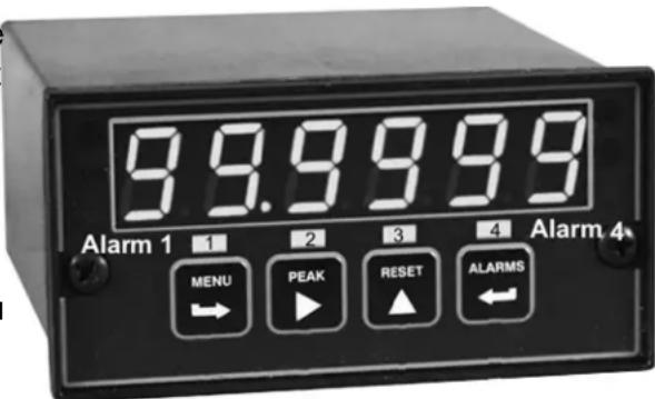
not be brought up if the dual relay board is detected. All relay boards offer a choice of operating modes: normally off or on, latched or non-latched, hysteresis band, deviation band, alarm based on filtered or unfiltered signal, and selectable number of readings in alarm zone for alarm. The source compared to the setpoint may be the displayed item or a non-displayed item. Please see the Glossary at the end of this manual for an explanation of special terms.
VIEWING & CHANGING SETPOINTS
The ← (Alarms) key can be used to step through and view setpoints while the meter continues to make conversions and performs setpoint control. If the ▶ Peak) key is pressed while a setpoint is displayed, conversion stops and the setpoint can be changed. After pressing , ← you have 30 seconds, or the meter reverts to the normal display. To view setpoints, menu item Loc4, digit 4, must have been set to 0. To change setpoints, menu item Loc2, digit 6, must have been set to 0.
| ALARMSPress AlarmsKey | Press Digit Select Key Select Key | Press Value Select Key |
3950.00 → (alarms) to display Alarm 1 setpoint. → (alarms) to display Alarm 1 setpoint. | 3950.00 nt setpoint 1 value blinks, and Alarm 1 LED indicator lights. Press ► to select a digit, which will blink. nt setpoint 1 value blinks, and Alarm 1 LED indicator lights. Press ► to select a digit, which will blink. | 3050.00To change setpoint 1 value, press ▲to change selected blinking digits. |
 .00Press (alarms) to display Alarm 2 setpoint. .00Press (alarms) to display Alarm 2 setpoint. |  .00Current setpoint 2 value blinks, and Alarm 2 LED indicator lights. Press ► to select a digit, which will blink. .00Current setpoint 2 value blinks, and Alarm 2 LED indicator lights. Press ► to select a digit, which will blink. | 3050.00To change setpoint 2 value, press ▲to change selected blinking digits. |
 .00Press (alarms) to display Alarm 3 setpoint. .00Press (alarms) to display Alarm 3 setpoint. |  .00Current setpoint 3 value blinks, and Alarm 3 LED indicator lights. Press ► to select a digit, which will blink. .00Current setpoint 3 value blinks, and Alarm 3 LED indicator lights. Press ► to select a digit, which will blink. | 3050.00To change setpoint 3 value, press ▲to change selected blinking digits. |
 .00Press (alarms) to display Alarm 4 setpoint. .00Press (alarms) to display Alarm 4 setpoint. |  .00Current setpoint 4 value blinks, and Alarm 4 LED indicator lights. Press ► to select a digit, which will blink. .00Current setpoint 4 value blinks, and Alarm 4 LED indicator lights. Press ► to select a digit, which will blink. | 3050.00To change setpoint 4 value, press ▲to change selected blinking digits. |
 .24Press (alarms) again. Meter will reset and display the current reading. .24Press (alarms) again. Meter will reset and display the current reading. | ||
KEYSTROKES FOR SETUP
If the MENU key does not work, see Section 9 "Enabling & Locking Out Menu Items."
| MENU→Press Menu | PEAK▶Press Digit Select Key | RESET▲Press Value Select Key |
| Source ESource to compare to setpoint | 0000Setpoint 1 compared to: | 1. Filtered item 2 Item #21 Item #1 3 Item #3 |
| 0000Setpoint 2 compared to: | 1. Filtered item 2 Item #21 Item #1 3 Item #3 | |
| 0000Setpoint 3 compared to: | 1. Filtered item 2 Item #21 Item #1 3 Item #3 | |
| 0000Setpoint 4 compared to: | 1. Filtered item 2 Item #21 Item #1 3 Item #3 | |
| AL SEtAlarm Setup for relays 1 & 2 if detected.Press → until ALSEt is displayed. | 00000Relay state when alarm is active | 0 Relay 1 on Relay 2 on1 Relay 1 off Relay 2 on2 Relay 1 on Relay 2 off3 Relay 1 off Relay 2 off |
| 00000Alarm latching or non-latching (auto reset) (see Glossary) | 0 AL1 auto reset AL2 auto reset1 AL1 latching AL2 auto reset2 AL1 auto reset AL2 latching3 AL1 latching AL2 latching | |
| 00000Alarm operates at and above setpoint (active high) or at and below setpoint (active low). (see Glossary) | 0 AL1 active high AL2 active high1 AL1 active low AL2 active high2 AL1 disabled AL2 active high3 AL1 active high AL2 active low4 AL1 active low AL2 active low5 AL1 disabled AL2 active low6 AL1 active high AL2 disabled7 AL1 active low AL2 disabled8 AL1 disabled AL2 disabled | |
| 00000Hysteresis mode or band deviation mode (see Glossary) | 0 AL1 band deviation AL2 band deviation1 AL1 hysteresis AL2 band deviation2 AL1 band deviation AL2 hysteresis3 AL1 hysteresis AL2 hysteresis4 No deviation or hysteresis on menu.5 AL1 span hysteresis AL2 band deviation6 AL1 span hysteresis AL2 hysteresis7 AL1 span hysteresis AL2 span hysteresis | |
| 00000Number of consecutive readings in alarm zone to cause an alarm | 0 After 1 reading 4 After 16 readings1 After 2 readings 5 After 32 readings2 After 4 readings 6 After 64 readings3 After 8 readings 7 After 128 readings | |
| ALS 34Alarm Setup for relays 3 & 4 if detected. | 00000Relay state when alarm is active. | 0 Relay 3 on Relay 4 on1 Relay 3 off Relay 4 on2 Relay 3 on Relay 4 off3 Relay 3 off Relay 4 off |
| 00000Alarm latching or non-latching (auto reset).(see Glossary) | 0 Alarm 3 auto reset Alarm 4 auto reset1 Alarm 3 latching Alarm 4 auto reset2 Alarm 3 auto reset Alarm 4 latching3 Alarm 3 latching Alarm 4 latching | |
| 00000Alarm operates at and above setpoint (active high) or at and below setpoint (active low).(see Glossary) | 0 AL3 active high AL4 active high1 AL3 active low AL4 active high2 AL3 disabled AL4 active high3 AL3 active high AL4 active low4 AL3 active low AL4 active low5 AL3 disabled AL4 active low6 AL3 active high AL4 disabled7 AL3 active low AL4 disabled8 AL3 disabled AL4 disabled | |
| 00000Hysteresis mode or band deviation mode(see Glossary) | 0 AL3 band deviation AL4 band deviation1 AL3 hysteresis AL4 band deviation2 AL3 band deviation AL4 hysteresis3 AL3 hysteresis AL4 hysteresis | |
| 00000Number of consecutive readings in alarm zone to cause an alarm. | 0 After 1 reading 4 After 16 readings1 After 2 readings 5 After 32 readings2 After 4 readings 6 After 64 readings3 After 8 readings 7 After 128 reading |
| MENU→PressMenu | PEAK▶Press DigitSelect Key | RESET▲Press Value SelectKey |
| dEUn1HAlarm 1 hysteresis | 0.00000 0.00000 0.000000.000000 0.000000 0.000000 Select digit to flash | Select -9 thru 9 for flashing first digit, 0 thru 9 for other flashing digits. Alarms will activate above the setpoint by the value entered and deactivate below the setpoint by the value entered. For span hysteresis, the alarms will activate (deactivate) at the setpoint and deactivate (activate See Glossary. |
| DEUn2HAlarm 2 hysteresis | ||
| DEUn1bAlarm 1 band deviation | ||
| DEUn2bAlarm 2 band deviation | ||
| dEUn1hAlarm 1 span hysteresis | ||
| DEUn2hAlarm 2 span hysteresis | ||
| dEUn3HAlarm 3 hysteresis | ||
| DEUn4HAlarm 4 hysteresis | ||
| DEUn3bAlarm 3 band deviation | ||
| DEUn4bAlarm 4 band deviation |
15. SINGLE & DUAL ANALOG OUTPUT OPTIONS
Two versions of an analog board may be installed in the meter at rear panel jack position J4, adjacent to the signal conditioner board. Once installed, this board is recognized by the meter, which will bring up the appropriate menu items for it. These will not be brought up if an analog output board is not installed.
A single analog output version can be configured for unipolar 4-20 mA current, 0-20 mA current or 0-10V voltage, or bipolar -10 to +10V voltage (with a 20V voltage swing). Unipolar or bipolar operation is selected by a jumper.
A dual analog output version can be configured for two unipolar outputs, which can each be 4-20 mA, 0-20 mA or 0-10V. Current or voltage output is selected at each connector.
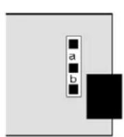
UNIPOLAR CONNECTIONS
4-20 mA or 0-20 mA OUTPUT
0-10V OUTPUT
ISOLATED GROUND

BIPOLAR CONNECTIONS
REFERENCE or RETURN
-10V to +10V OUTPUT
N/C

Unipolar current or voltage: Jumper a Bipolar -10 to +10 voltage: Jumper b

UNIPOLAR CONNECTIONS
4-20 mA or 0-20 mA OUTPUT 2
0-10V OUTPUT 2
ISOLATED GROUND
4-20 mA or 0-20 mA OUTPUT 1
0-10V OUTPUT 1
ISOLATED GROUND


No jumpers, only selections at the connectors.
With either board, current or voltage output is selected at the connector and in the Menu. The low analog output (0 mA, 4 mA, 0V, or -10V) may be set to correspond to any low displayed reading An_Lo. The high analog output (20 mA, 0V or 10V) may be set to correspond to any high displayed reading An_Hi. The meter will then apply a straight line fit between these two end points to provide an analog output scaled to the meter reading. The decimal point location is fixed by the dEC.Pt1 selection.
KEYSTROKES FOR SETUP OF SINGLE ANALOG OUTPUT BOARD
If the MENU - key does not work, see Section 9 "Enabling & Locking Out Menu Items."
  |   |   |
 Analog Output Setup. Press until AnSEt is displayed. Analog Output Setup. Press until AnSEt is displayed. |  Calibration output selection. Calibration output selection. | 0 0-20 mA current output1 0-10V voltage output2 4-20 mA current output3 -10V to+10V voltage output |
 Analog output source. Analog output source. | 0 Filtered item 2 Item 21 Item 1 3 Item 3 | |
 Low displayed value for -10V, 0V, 0 mA, or 4 mA Low displayed value for -10V, 0V, 0 mA, or 4 mA |  0.00000 0.00000 0.00000 0.00000  Select digit to flash Select digit to flash | Select 0 thru 9 for flashing digit. |
 High displayed value for 10V or 20 mA output High displayed value for 10V or 20 mA output |  0.00000 0.00000 0.00000 0.00000  Select digit to flash Select digit to flash | Select 0 thru 9 for flashing digit. |
KEYSTROKES FOR SETUP OF DUAL ANALOG OUTPUT BOARD
If the MENU key does not work, see Section 9 "Enabling & Locking Out Menu Items."
| Press Menu Key | Press Digit Select Key | Press Value Select Key |
| An_SEt Analog Output Setup. Press → until AnSEt is displayed. |   | 0 0-20 mA current output1 0-10V voltage output2 4-20 mA current output |
  | 0 Filtered item 2 Item 21 Item 1 3 Item 3 | |
  | 0 0-20 mA current output1 0-10V voltage output2 4-20 mA current output | |
  | 0 Filtered item 2 Item 21 Item 1 3 Item 3 | |
| An_Lo1 Low displayed value for 0V, 0 mA, or 4 mA output |  0.00000 0.00000 0.00000 0.00000 0.00000 0.00000 0.00000 0.00000 | Select 0 thru 9 for flashing digit. |
| An_Hi1 High displayed value for 10V or 20 mA output |  0.00000 0.00000 0.00000 0.00000 0.00000 0.00000 0.00000 0.00000 | Select 0 thru 9 for flashing digit.dEC.Pt1 selection. |
| An_Lo2 Low displayed value for 0V, 0 mA, or 4 mA output |  0.00000 0.00000 0.00000 0.00000 0.00000 0.00000 0.00000 0.00000 | Select 0 thru 9 for flashing digit. |
| An_Hi2 High displayed value for 10V or 20 mA output |  0.00000 0.00000 0.00000 0.00000 0.00000 0.00000 0.00000 0.00000 | Select 0 thru 9 for flashing digit. |
16. SERIAL COMMUNICATIONS OPTIONS
A serial communications board may be connected to the meter main board at plug position P13 (middle position). Available boards are RS232, RS485 (with dual RJ11 connectors), RS485 Modbus (with dual RJ45 connectors), USB, USB-to-RS485 converter. The dual connectors of RS485 boards are wired in parallel to allow daisy chaining of addressable meters without use of a hub. Three serial communication protocols are selectable for all serial boards: Custom ASCII, Modbus RTU, and Modbus ASCII.
A USB-to-RS485 converter board allows a meter to be interfaced to a computer and be the device server for a network of up to 31 other meters on an RS485 bus, while itself retaining all capabilities of a meter. The remote meters need to be equipped with our RS485 digital interface board with dual 6-pin RJ11 jacks, not our RS485 digital interface with dual 8-pin RJ45 jacks. The dual 6-pin RJ11 jacks on the RS485 board are wired in parallel to allow multiple meters to be daisy-chained using readily-available 6-wire data cables with no need for hand-wiring or an RS485 hub. The outer two wires are used for ground.
Use 6-wire, straight-through data cables, not 4-wire telephone cables or crossover cables, all the way from the device server to the last device on the RS485 bus. Connect ATX to ATX, BTX to BTX, etc., with no crossover as you go from device to device.
To connect a meter with a USB board to a computer, use a USB cable with Type A and Type B connectors. The computer will display “Found new Hardware” followed by “Welcome to the Found new Hardware Āizard.” Follow the instructions for software installation from a CD. Āhen the installation is complete, use Device Manager to determine the com port. To get to Device Manger, go to the Windows Control Panel, click on System, click on the Hardware tab, then click on Device Manager. Go down the device list and click on Ports (COM & LPT) and USB serial port (com #). Note the com port # for use with communications to your meter, then exit Control Panel. If you later need to change the Com port, right-click on USB serial port (com #), then on Properties, Port settings, and Advanced. Change port to the desired number, click OK, then exit Control Panel.
BOARD SETUP VIA JUMPERS
USB Board
No jumpers required.
USB
USB
| RS232 Boarde - Normal operation.f - Slave display to RS232 from another meter.g - Pull-up resistor on RTS line.Note: Board is shipped with jumpers e and g installed |  |
| RS485 Board, Full Duplex Operationb & d - Installed on last meter in long cable run.RS485 Board, Half Duplexa & c - Installed for half duplex operation.d - Installed on last meter in line with long cable runs.Note: Board is shipped with no jumpers installed. |  |
| RS485-Modbus Board, Full Duplex Operationb & e - Bias jumpers should be installed on 1 board.a & d - Installed on last meter in long cable run.RS485-Modbus Board, Half Duplex Operationb & e - bias jumpers installed on 1 board.c & f - installed for half duplex operation.a - installed on last meter in line with long cable runs.Note: Board is shipped with no jumpers installed. |  |
| USB-to-RS485 Converter BoardFull Duplex OperationNo jumpers for short cable runs.Add b & d for long cable runs.Half Duplex Operationa + c for short cable runs.Add d for long cable runs. |  |
SERIAL CONNECTION EXAMPLES
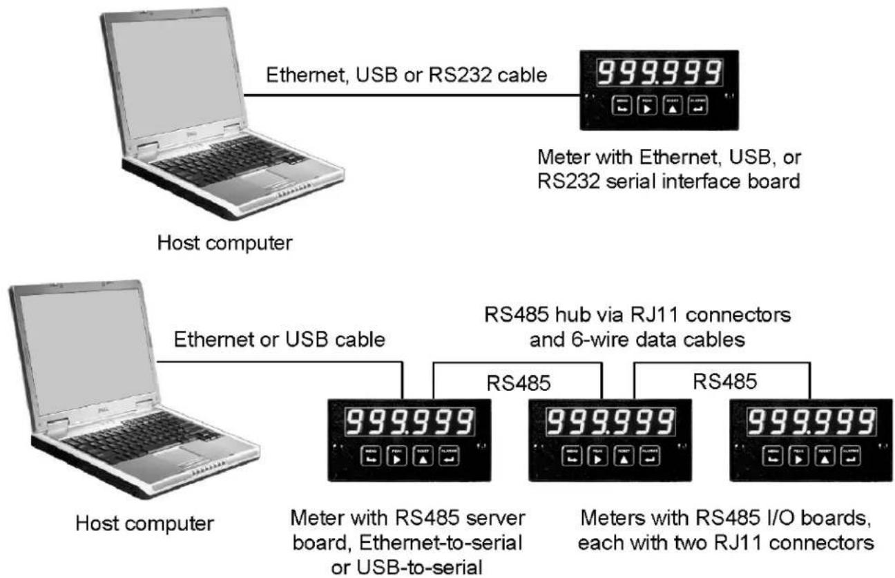
flowchart
graph TD
    A["Host computer"] -->|Ethernet, USB or RS232 cable| B["999.999"]
    B --> C["Meter with Ethernet, USB, or RS232 serial interface board"]
    D["Host computer"] -->|Ethernet or USB cable| E["999.999"]
    E --> F["Meter with RS485 server board, Ethernet-to-serial or USB-to-serial"]
    F --> G["RS485 hub via RJ11 connectors and 6-wire data cables"]
    G --> H["999.999"]
    H --> I["Meters with RS485 I/O boards, each with two RJ11 connectors"]
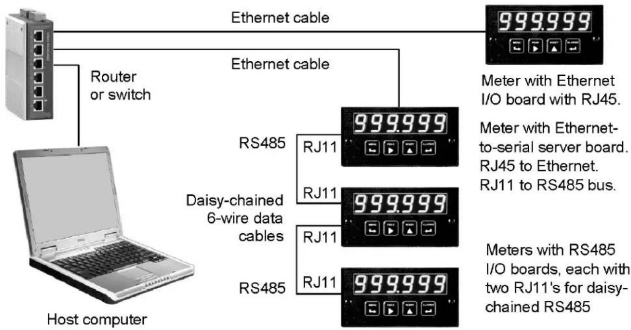
flowchart
graph TD
    A["Host computer"] -->|Router or switch| B["Router"]
    B --> C["Ethernet cable"]
    C --> D["999.999"]
    D --> E["Meter with Ethernet I/O board with RJ45."]
    C --> F["RS485"]
    F --> G["RJ11 999.999"]
    F --> H["RJ11 999.999"]
    F --> I["RJ11 999.999"]
    F --> J["RJ11 999.999"]
    F --> K["RJ11 999.999"]
    L["Host computer"] --> M["Daisy-chained 6-wire data cables"]
    M --> N["RJ11 999.999"]
    M --> O["RJ11 999.999"]
    M --> P["RJ11 999.999"]
    M --> Q["RJ11 999.999"]
    R["Host computer"] --> S["Meters with RS485 I/O boards, each with two RJ11's for daisy-chained RS485"]

flowchart
graph TD
    A["Router"] --> B["Internet & modems"]
    B --> C["Router"]
    C --> D["Ethernet-to-serial server"]
    D --> E["RS485 via 6-wire data cables"]
    D --> F["RS485 via discrete wires"]
    D --> G["Transmitters"]
    H["Host computer"] --> I["Computer"]
    style A fill:#f9f,stroke:#333
    style H fill:#ccf,stroke:#333
    style B fill:#cfc,stroke:#333
    style C fill:#fcc,stroke:#333
    style D fill:#cff,stroke:#333
    style E fill:#ffc,stroke:#333
    style F fill:#ffc,stroke:#333
    style G fill:#ffc,stroke:#333
KEYSTROKES FOR SETUP
If the MENU key does not work, see Section 9 "Enabling & Locking Out Menu Items."
| MENU→Press Menu Key | PEAK▶Press Digit Select Key | RESET▲Press Value Select Key |
| Ser 1Serial Setup 1.Press →tilSer 1 is displayed.Fixed ParametersNo parity8 data bits1 stop bit | 000Output filtering | 0 Send unfiltered signal1 Send filtered signal |
| 000Baud rate | 0 300 baud 4 4800 baud1 600 baud 5 9600 baud2 1200 baud 6 19200 baud3 2400 baud | |
| 000Digital output rate.rr = reading rate.rr depends on gate time and input frequency. | 0 Output at reading rate rr.1 Output at rr/2 5 Output at rr/322 Output at rr/4 6 Output at rr/643 Output at rr/8 7 Output at rr/1284 Output at rr/16 3 Output at rr/256 | |
| Ser 2Serial Setup 2 | 0000Line feed | 0 No LF after carriage return1 LF after carriage return |
| 0000Alarm data with readings | 0 No alarm data1 Alarm data with reading | |
| 0000Output mode control | 0 Continuous data output1 Data output on ASCII command only | |
| 0000Meter address with CustomASCII protocol* | Select 0 thru F for addresses 1 thru 15.Select 0. thru F (with decimal point) for addresses 16 thru 31. | |
 Press Menu Key Press Menu Key |  Press Digit Select Key Press Digit Select Key |  Press Value Select Key Press Value Select Key |
| Ser 3Serial Setup 3 | Half or full duplex | Full duplex Half duplex |
  | *(asterisk) is recognition character.No start & stop characters.Custom recognition character.No start & stop characters.* (asterisk) is recognition character.Special start & stop characters.Custom recognition characters.Special start & stop characters. | |
| RTS mode | Normal RTS Single transmission | |
| termination cha-racters. | Only at end of all itemsAt end of each item | |
 | All Active ItemsItem #1 onlyItem #2 only (if active)Item #3 only (if active)Peak onlyDisplayed ItemValley onlyAll Active Items + Peak + Valley | |
| Ser 4Serial Setup 4 | 000Modbus* ASCII gap timeout | 1 sec3 sec5 sec10 sec |
| 000Serial protocol | Custom ASCII*Modbus* RTUModbus* ASCII | |
| 000Parity | NoneOddEven | |
| AddrModbus Address | 00000000Select digit to flash. | 158elect 0 thru 9 for flashing digit.ddress range is 1 to 247. |


17. EXCITATION OUTPUT & POWER SUPPLY
Three isolated transducer excitation output levels are available from the power supply board. These are selectable via jumpers b, c, d, e, f in the upper right of the board, as illustrated. In addition, the board provides three jumper positions for special features. The same jumper locations apply to the universal power supply (85-264 Vac or 90-300 Vdc) and to the low voltage power supply (12-32 Vac or 10-48 Vdc).
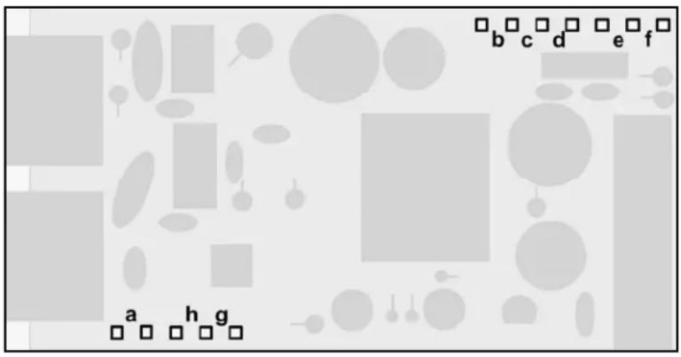
- Letters indicate jumper position. Jumpers are installed on pins adjacent to letters.
| Excitation output Jumper locations | ||
| 5 Vdc ±5%, 100 mA max10 Vdc ±5%, 120 mA max24 Vdc ±5%, 50 mA max | b, d, eb, d, fc |  |
Jumper a - Front panel menu lockout, locked when installed. See Section 9.
Jumper g - Provides +5V power output at P1-4 when installed.
Jumper h - Connects "Digital Input B" to P1-4 when installed.
18. INSTRUMENT SETUP VIA PC
Instrument Setup software is a PC program which is much easier to learn than front panel programming. It is of benefit whether or not the meter is connected to a PC. Āith the meter connected to a PC, it allows uploading, editing and downloading of setup data, execution of commands under computer control, listing, plotting and graphing of data, and computer prompted calibration. Āith the meter unconnected to a PC, it provides quick selection of jumper locations and a printable display of menu selections for front panel setup.
SOFTWARE INSTALLATION
Download /S2*.exe onto your PC from the web or the distribution CD. Double-click on the downloaded file to unzip it into a special directory, such as c:\temp. Aithin that directory, double-click on setup.exe, which will install the software on your PC.
PREREQUISITES FOR CONNECTED USE
1) PC with available RS232 com port.
2) Meter to be set up.
3) RS232 board in meter. This board can be used for setup, then be removed.
4) RJ11-to-DB9 RS232 cable to connect meter and PC (see Section 1, Ordering Guide).
5) Instrument Setup software.

RJ11-to-DB9 RS-232 cable
ESTABLISHING COMMUNICATIONS
Connect the meter and PC. Apply power to the meter. Be sure that the meter is in Run Mode, not Setup Mode. To start the software from Windows, click on Start => Programs => IS2 => IS2. Click on RS232 => Establish. The program will temporarily set the selected Com port to the required baud rate, parity, data bits and stop bit. Once communications have been established, click on Main Menu. The software will sense the type of meter and installed boards, but it cannot sense jumpers positions nor set jumpers for you. If the computer is not connected to a meter, select Counter/Timer and Series 2.


SETUP OF CONNECTED METER
A setup file can be retrieved from the meter (Counter => Get Setup), be edited (View => Setup), be saved to disk (File => Save Setup), be retrieved from disk (File => Open Setup), and be downloaded into one or multiple meters (Counter => Put Setup). Downloading of setup files from a PC can be a major time saving when multiple counters have to be set up in the same way.
You will find that Instrument Setup software is very user friendly, with separate tab-selectable windows for Input+Display, Scaling, Filter, Relay Alarms, Communications, Analog Out, and Lockouts. If the required hardware, such as the analog output board, is not sensed, the corresponding tab will be grayed out.
ADDITIONAL FEATURES WHEN CONNECTED
- The Commands pull-down menu allows you to perform Reset functions, to enter numerical values into the meter, and to retrieve numerical values from the meter (Items 1, 2, 3, Peak, Valley).
line
| Time | Value | |------|-------| | 0 | 2825 | | 1 | 2825 | | 2 | 2815 | | 3 | 2805 | | 4 | 2845 | | 5 | 2860 | | 6 | 2780 | | 7 | 2750 | | 8 | 2830 | | 9 | 2845 | | 10 | 2845 |Plot

bar
| X-Axis | Frequency | |---|---| | 2725.0 | 32 | | 2726.0 | 31 | | 2727.0 | 34 | | 2728.0 | 39 | | 2729.0 | 45 | | 2730.0 | 51 | | 2731.0 | 68 | | 2732.0 | 1034 | | 2733.0 | 316 | | 2734.0 | 331 | | 2735.0 | 400 | | 2736.0 | 560 | | 2737.0 | 940 | | 2738.0 | 360 | | 2739.0 | 115 | | 2740.0 | 68 | | 2741.0 | 108 | | 2742.0 | 115 | | 2743.0 | 88 | | 2744.0 | 68 | | 2745.0 | 48 | | 2746.0 | 38 | | 2747.0 | 38 | | 2748.0 | 38 | | 2749.0 | 38 | | 2750.0 | 38 | | 2751.0 | 38 | | 2752.0 | 38 | | 2753.0 | 38 | | 2754.0 | 38 | | 2755.0 | 38 | | 2756.0 | 38 | | 2757.0 | 38 | | 2758.0 | 38 | | 2759.0 | 38 | | 2760.0 | 38 | | 2761.0 | 38 | | 2762.0 | 38 | | 2763.0 | 38 | | 2764.0 | 38 | | 2765.0 | 38 | | 2766.0 | 38 | | 2767.0 | 38 | | 2768.0 | 38 | | 2769.0 | 38 | | 2770.0 | 38 | | 2771.0 | 38 | | 2772.0 | 38 | | 2773.0 | 38 | | 2774.0 | 38 | | 2775.0 | 38 | | 2776.0 | 38 | | 2777.0 | 38 | | 2778.0 | 38 | | 2779.0 | 38 | | 2780.0 | 38 | | 2781.0 | 38 | | 2782.0 | 38 | | 2783.0 | 38 | | 2784.0 | 38 | | 2785.0 | 38 | | 2786.0 | 38 | | 2787.0 | 38 | | 2788.0 | 38 | | 2789.0 | 38 | | 2790.0 | 38 | | 2791.0 | 38 | | 2792.0 | 38 | | 2793.0 | 38 | | 2794.0 | 38 | | 2795.0 | 38 | | 2796.0 | 38 | | 2797.0 | 38 | | 2798.0 | 38 | | 2799.0 | 38 | | 2800.0 | 512 | | Peak (Continue) | ~115 (approximate peak) | | Peak (New Scale) | ~115 (approximate peak) | | Peak End (End Scale) | ~115 (approximate peak) | | Peak Print (Print) | ~115 (approximate peak) | | Peak Save (Save) | ~115 (approximate peak) | | Peak Pause (Pause) | ~115 (approximate peak) | | Peak Continue (Continue) | ~115 (approximate peak) | | Peak New Scale (New Scale) | ~115 (approximate peak) | | Peak End (End Scale) | ~115 (approximate peak) |Graph
- The Readings pull-down menu provides three formats to display meter data on the PC monitor. Use the Pause and Continue buttons to control the timing of data collection, then press Print for a hardcopy record on your PC printer.
- List presents the latest readings in a 20-row by 10-column table. Press Pause at any time to freeze the display. This is one method to capture peak readings.
- Plot generates a plot of readings vs. time in seconds. It effectively turns the DPM-PC combination into a printing digital oscilloscope.
- Graph generates a histogram, where the horizontal axis is the reading and the vertical axis is the number of occurrences of readings. The display continually resizes itself as the number of readings increases.
- The Jumpers pull-down menu shows board jumper corresponding to specific user selections.
- The Calibration pull-down menu allows easy frequency calibration of the quartz crystal. Simply apply a known calibration frequency up to 1 MHz to Channel A of the dual channel signal conditioner board, type in the frequency value in Hz, and press Enter.
METER SETUP WITH AN UNCONNECTED PC
Instrument Setup software is also of benefit when the PC is not connected to a meter.
Upon launching the software, click on None for Communications, then on Counter/Timer and Series 2. Click on File => Default Setup to retrieve a default setup file from disk, or on File => Open Setup to retrieve a previously saved setup file from disk.
To enter new setup information, click on View => Setup, then make your screen selections as if you were connected to a meter. Tabs will be grayed out if you have not selected the required hardware under the Input+Display tab. Âhen done, press on Main Menu, then on View => Menu. The selections made under Setup will now be shown in the form of the required front panel programming sequence, where each row corresponds to a menu item selected by the → key, and the seven data columns correspond to values entered via the ▶ and ▶ keys.
Click on any step in the sequence to bring up a detailed help window.
Click on Print for a hardcopy, which you can then use as an instruction sheet to program your meter via its front panel.
Click on Main Menu => File => Save Setup As to save your setup to disk and have an electronic record.
| Dig. No. | S | 1 | 2 | 3 | 4 | 5 | 6 |
| InPut | r | A | t | E | |||
| SEtuP | 0 | 0 | 0 | 0 | 0 | ||
| ConFiG | 0 | 1 | 0 | 0 | |||
| dSPyno | 0 | 1 | |||||
| GAtE t | 0 | 0 | 0. | 1 | 0 | ||
| ti Out | 0 | 0 | 3. | 0 | 0 | ||
| FiLtEr | 0 | 0 | 0 | 1 | 1 | ||
| SLOPE | 0 | 1 | |||||
| DecPt1 | 1 | 1 | 1 | 1 | 1 | 1. | |
| DecPt2 | 2 | 2 | 2 | 2 | 2 | 2. | |
| SCALE1 | + | 1. | 0 | 0 | 0 | 0 | 0 |
| OFFSt1 | + | 0 | 0 | 0 | 0 | 0 | 0 |
| SCALE2 | + | 1. | 0 | 0 | 0 | 0 | 0 |
| OFFSt2 | + | 0 | 0 | 0 | 0 | 0 | 0 |
| SourcE | 1 | 1 | |||||
| AL SEt | 0 | 0 | 0 | 0 | 0 | ||
| dEUn1b | + | 0 | 0 | 0 | 0 | 0 | 0 |
| dEUn2b | + | 0 | 0 | 0 | 0 | 0 | 0 |
| SEr 1 | 0 | 5 | 0 | ||||
| SEr 2 | 0 | 0 | 1 | 1 | |||
| SEr 3 | 0 | 0 | 0 | 0 | 1 | ||
| SEr 4 | 0 | 1 | 0 | ||||
| Addr | 0 | 0 | 1 | ||||
| CALib | - | 0 | 0 | 1 | 0 | 0 | |
| Loc 1 | 0 | 0 | 0 | 0 | |||
| Loc 2 | 0 | 0 | 0 | 0 | |||
| Loc 3 | 0 | 0 | 0 | 0 | |||
| Loc 4 | 0 | 0 | 0 | 0 |
19. CUSTOM CURVE LINEARIZATION
Curve.exe is a DOS-based, executable PC program used to set up an Extended meter so that the readings have a user-defined, non-linear relationship with the input signal. For example, it allows a meter to correct for non-linearity of transducers, or to display volume from pressure at the bottom of an irregularly shaped tank. The linearizing parameters are downloaded into non-volatile memory of the meter. The curve fitting algorithm is uses quadratic segments of varying length and curvature, and provides diagnostics to estimate curve fitting errors. The program is self-prompting, avoiding the need for a manual.

PREREQUISITES
1) PC-compatible computer with an available RS232 or USB port.
2) Extended meter*.
3) A serial communication board in the meter. This board can be removed following meter setup.
4) A suitable cable to connect the meter to a PC.
5) Curve.exe software (downloadable at no charge).
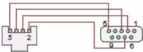
RJ11-to-DB9 RS-232 cable
GETTING STARTED
Download curve.exe into the same directory that will contain your data files, such as c:\curves. Set the meter to custom curve linearization. To do so, press the → key to get to ConFG, then set the fifth digit to 1. This digit will only be displayed with an Extended meter*. Set the meter baud rate to 9600. To do so, press the → key to get to SEr 1, then set the entry to 050. Set the meter address to 1. To do so, press the → key to get to SEr 2, then set the entry to 0011. To execute the program from Aïndows, simply double-click on curve.exe. No software installation is required.
OPERATING MODES
The program will prompt you to enter your data in one of four modes. Pressing R (Enter) at any time returns you to the main menu.
1) Text file entry mode, with an X value in one column and a Y value in another. There can be additional columns, which are ignored. The file must have a DOS name of up to 8 characters and the extension .RAÄ. There can be from 5 to 180 rows. X is the input value and should be in the unit of measure for which the meter was set up, such as mV, V, mA or A. Y is the desired corresponding reading and can range from -99999 to 99999 with any decimal point.
2) 2-coordinate keyboard entry mode, where an actual X input signal is applied, and the desired Y reading is entered from the keyboard.
3) 2-coordinate file entry mode, where an actual X input signal is applied, and the desired Y reading is provided from a file.
4) Equation entry mode, where the coefficients of a polynomial Y = K1XP1 + K2XP2 + K3*XP3 + ... are entered. Up to 20 terms are allowed. And offset can be built into X.
REQUIRED USER INPUTS
- Select CTR
- You will be asked to supply the following:
LOÃ X-COORDINATE VALUE > LOÃ INPUT MEASUREMENT VALUE > HIGH X-COORDINATE VALUE > HIGH INPUT MEASUREMENT VALUE >
This informs the computer of your signal conditioner jumper settings. Enter 0 and 0 for the two LOA values. For HIGH X, enter your signal conditioner jumper range in the same units of measure that you will be using in your *.RAA data input file. Enter 20 for 20 mA or 10 for 10V. For HIGH INPUT MEASUREMENT VALUE, enter 100000,
You will be asked to select the position of the decimal point from 6=X.XXXXX, 5=XX.XXX, 4=XXX.XXX, 3=XXXX.XX, 2=XXXXX.X, 1=XXXXXX (for DPMs, the leading X is a blank). Specify the same position that you specified in the dEc.Pt1 decimal point menu selection.
20. METER CALIBRATION
All ranges of the meter have been digitally calibrated at the factory prior to shipment using computers and calibration equipment certified to NIST standards. If recalibration is required, the meter may be returned to the factory or to any authorized distributor.
For frequency and rate measurements with the dual-channel signal conditioner, a calibration correction to the quartz crystal oscillator is stored in EEPROM on the main board. Calibration constants are also stored in EEPROM in the process receiver & totalizer signal conditioner board and in the analog output board. As a result, these two boards can be mixed and interchanged without requiring recalibration.
For frequency calibration using the dual-channel signal conditioner board, calibration may be performed in the field as follows using the front panel pushbuttons:
- Set InPut to rAtE and A only.
- Enter 0 in CALib to set initial correction to 0 PPM.
- Set SCALE to -9.99999
- Set OFFSt1 to 999999
- Apply a 100 kHz reference signal to channel A.
- Enter the displayed reading in CALib.
For calibration of the process receiver & totalizer signal conditioner board or analog output board, an RS-232 board must be installed in the meter for serial communication with a PC. This board may be removed upon completion of calibration. Calibration software and step-by-step instructions are available from the factory.
21. SPECIFICATIONS
DISPLAY
Type 6 LED digits, 7-segment, 14.2mm, plus 4 LED indicators
Digit Color ....Red or green
Display Range -999999 to +999999
CONVERSION (FREQUENCY INPUT)
Conversion Technique 1/period
Conversion Rate......Gate Time + 30 ms + 2 signal periods (max)
Gate Time 0 to 199.99 sec (selectable)
Time Before Zero Output (Time-Out) 0 to 199.99 sec (selectable)
Output & Display Update Rate Same as conversion rate
Time Base Accuracy Calibrated to ±2 ppm
INPUT ISOLATION
CMV from DC to 60 Hz....Äithstand 250Vac
Dielectric strength.... 3.5 kV ac for 5 sec, 2.3 kV ac for 1 min
DUAL CHANNEL SIGNAL CONDITIONER
Accuracy at 25°C....±2 ppm
Tempco ....±1 ppm/degree C
Long-Term Drift of Crystal ....±5 ppm/year
Signal Types...... AC, NPN, PNP transistor outputs, contact closures, magnetic pickups
Max Pulse Rate ....1 MHz on Channel A, 250 kHz on Channel B
Channel Isolation....Channel A & channel B share common ground
Low Pass Filter....250 Hz or 30kHz (selectable)
Hysteresis 15 mV to 2.2 Vp-p (selectable)
Trigger level....±15 mV to ±1.7 V (selectable)
Debounce Circuitry.... 0, 3, 50 ms (selectable)
PROCESS RECEIVER & TOTALIZER SIGNAL CONDITIONER
Signal Levels....0-1 mA, 4-20 mA, 0-10 V (selectable)
Accuracy at 25°C.... ±0.025%
Span Tempco....±0.003% of reading /°C
Zero Tempco....±0.003% of full scale /°C
QUADRATURE SIGNAL CONDITIONER
Signal Type ....Differential or single-ended quadrature
Transitions Monitored....x1, x2 or x4
Max Pulse Rate 250 kHz at x1, 125 kHz at x2, 62.5 kHz at x4
Differential high threshold voltage ....+200 mV
Differential low threshold voltage....-200 mV
Single-ended high voltage....2.5V to 10V
Single-ended low voltage ....-1V to +1V
Input resistance, typ. 17 kOhm
Conversion Technique for Rate....1/period
Conversion Time for Rate ...... Gate time + 30 ms + 0-2 signal periods
Time Before Zero Output for Rate....0 to 199.99 sec (selectable)
Zero Āait Time for Rate ....0 to 199.99 sec (selectable)
Output & Display Update Rate .... Same as conversion rate
Time Base Accuracy for Rate.... Calibrated to ±2 ppm
POWER REQUIREMENTS
Input Voltage rating (standard)....85-264 Vac or 90-300 Vdc
Input Voltage rating (low voltage option) 12-32 Vac or 10-48 Vdc
Power Line Frequency ...... DC and 47-63 Hz
Power Consumption, Max 5 Åatts
EXCITATION OUTPUTS
Voltage & Current Levels (jumper selectable) 5V dc ±5%, 100 mA max
10V dc ±5%, 120 mA max
24V dc ± 5%, 50 mA max
Excitation Output Ripple....100 mVp max
Isolation from power and outputs 250 Vac
Insulation dielectric strength to power and outputs..... 3.5 kV ac for 5 sec, 2.3 kV ac for 1 min
Isolation to signal common.... 50V dc
DUAL OR QUAD RELAY OPTIONS
Power to Relay Option ......Powered by meter
Setpoint Setup.... Via front panel pushbuttons or RS232/485
Update Rate 56/s at 60 Hz, 47/s at 50 Hz
Response to input signal (min).....Display update rate
Input Signal (selectable)....Filtered or unfiltered input signal
Actuation Modes (selectable) ..... Above or below setpoint, latching or non-latching, disabled
Output Time Delay (selectable)....1 to 128 readings
Front Panel Enable / Lockout Modes (selectable)....1) Display and change setpoints
2) Display but do not change setpoints
3) Neither display nor change setpoints
Alarm Status Indication ....2 or 4 red LED lamps
Status Indication Setup (selectable) ...... Lit when output is ON or OFF
Form C, SPDT Relay Output:
AC Rating 8A @ 240 Vac
DC Rating....8A @ 24 Vdc
Isolation rating between signal common and contacts 250 Vac
Insulation dielectric strength between signal common and contacts ....
3.5 kV ac for 5 sec, 2.3 kV ac for 1 min
Form A, SPST Solid State Relay Output:
AC Rating....130 mA @ 140 Vac
DC Rating....130 mA @ 180 Vdc
Isolation rating between signal common and contacts 250V ac
Insulation dielectric strength between signal common and contacts ....
3.5 kV ac for 5 sec, 2.3 kV ac for 1 min
ANALOG OUTPUT OPTION
Power to Analog Output Option....Powered by meter
Output Levels, Single Analog Output Option.... 0-20 mA, 4-20 mA, 0-10V, -10 to +10V
Output Levels, Dual Analog Output Option 0-20 mA, 4-20 mA, 0-10V
Voltage Compliance, 0-20 mA Output 12V (0-600 Ohm load)
Current Compliance, 0-10V Output ....2 mA (5 kOhm or higher load)
Accuracy ......Meter input accuracy ±0.02% of full scale analog output
Resolution 16 bit (1 part in 65,536)
Response Time .... meter update rate
Scaling of Reading for Zero Output....-999,999 to +999,999
Scaling of Reading for Full Scale Output....-999,999 to +999,999
Isolation rating between signal common and analog output 250V ac
Insulation dielectric strength between signal common and analog output......
3.5 kV ac for 5 sec, 2.3 kV ac for 1 min
SERIAL INTERFACE OPTION (USB, RS232, RS485, RS485-Modbus boards)
Output Types....RS232, RS485, RS485-Modbus, USB
USB-to-RS485 converter
Power to Interface Option....Powered by meter
RS485 Airing....Half or full duplex
Baud Rates 300, 600, 1200, 2400, 4800, 9600, 19200
Serial Protocols ...... Custom ASCII, Modbus RTU, Modbus ASCII (selectable)
Signal Levels.... Meet RS232, RS485, USB standards
Isolation rating between signal common and serial I/O 250V ac
Insulation dielectric strength between signal common and serial I/O ....
3.5 kV ac for 5 sec, 2.3 kV ac for 1 min
Option Board Connectors:
RS232 Single RJ11 jack
RS485 Two RJ11 jacks (for daisy chaining with 6-wire data cables)
RS485 Modbus.....Two RJ45 jacks (for daisy chaining with 8-wire data cables)
USB.... USB type B plug
USB-to-RS485 converter....USB type B plug plus RJ11 jack to RS485 bus
ENVIRONMENTAL
Operating Temperature 0°C to 55°C
Storage Temperature ....-40°C to 85°C
Relative Humidity ....95% from 0°C to 40°C, non-condensing
Case...... NEMA-4X (IP65) from front when panel mounted (not verified for UL)
Shock 10 G at 1 kHz, applied in X, Y, Z axes
Vibration 15 Hz to 150 Hz, 1 mm to 2 mm amplitude, 20 G max.
22. GLOSSARY OF TERMS
Adaptive filter threshold
A threshold which causes an adaptive moving average filter to be reset to the latest reading when the accumulated difference between individual readings and the filtered reading exceeds that threshold. Adaptive moving average filtering allows a meter to respond rapidly to actual changes in signal while filtering out normal noise. The accumulated difference is also reset to zero when the latest reading has a different polarity than the filtered reading. A low____ adaptive filter threshold is normally selected. A high filter threshold should be selected if the signal has large transients.
Alarm, latched
An alarm which stays actuated until reset. Latched alarms can shut down machinery or a process when an operating limit has been exceeded, or maintain an alarm condition until acknowledged by an operator.
Alarm, non-latched
An alarm which changes state automatically when the reading rises above a specified limit and changes back automatically when the reading falls below a limit.
Autofilter A selectable digital filter mode which automatically selects an appropriate moving average filter time constant from 0.08 sec to 9.6 sec for the encountered noise condition.
Batch control An operating mode of the Extended counter with a relay board, where the counter is used to control repetitive fill operations by counting up from zero to a preset, or counting down from a preset to zero.

line
| Time | Meter Reading | |------|---------------| | 0 | 0 | | Peak | ON | | End | ON |
line
| Time | Meter Reading | |------|---------------| | Off | 1000 | | ON | 1000 |Calculated total
While most totals are based on direct pulse counts, certain totals are calculated as running totals based on displayed rate (e.g., Total A, Rate A). The totalizing process assumes that rate is displayed in units per second, such as 300 gallons per second, allowing a scale factor of 1 to be used. If the rate is not in units per second, a different scale factor has to be applied.
Coordinates of 2 points method
A scaling method where the coordinates of 2 points are entered. For a pulse rate input, the first entered point is would be low frequency in Hz and low desired reading. The second entered point would be high frequency in Hz and high desired reading.
Counts The reading displayed on the meter ignoring the decimal point.
Custom ASCII protocol
A simplified, short protocol for use with panel meters, counters and timers. It allows 31 digital addresses. Not an industry-standard protocol, like the more complex Modbus protocol, which is also offered with these instruments.
Custom curve
A user-specified nonlinear relationship between the input signal and displayed reading. Custom curve linearization is available with the Extended counter. One way to supply the data is via a text file with up to 180 data points, which is processed on a PC using furnished software and is then downloaded into EEPROM via serial communications.
Cutoff A programmable threshold in units of flow applicable to Total and Batch Control with the process receiver and totalizer signal conditioner. Flow rates below the cutoff, deemed to be zero offset errors, will not be totalized. Otherwise, small zero offset errors could result in a large error if accumulated over a long time.
Deviation band
A band in counts which controls relay action symmetrically around a setpoint. The relay actuates when the reading falls within the deviation band, and de-actuates when the reading falls outside of this band. A deviation limit (e.g., 50 counts) is set up around both sides of the setpoint to create a deviation band (e.g., 100 counts). Setting up a passband around a setpoint is often used for component testing. Deviation limits are programmed by entering menu item dEUn1b for Al
scatter
| Parts | Reading | |-------|---------| | Fail | 950 | | Fail | 975 | | Fail | 1000 | | Pass | 950 | | Pass | 975 | | Pass | 1000 | | Setpoint | 950 | | Setpoint | 975 | | Setpoint | 1000 |Duty cycle ON or OFF period of square waves as a percentage of total period over a gate time which is selectable from 10 ms to 199.99 sec. Āith the dual input signal conditioner, the same signal is applied to Channels A and B. Duty cycle can then be read out with resolution to 0.01%.
Extended counter
A counter with an enhanced microcomputer main board that provides added capabilities, such as custom curve linearization of nonlinear inputs and display of rate of change from successive readings.
Frequency Rate in cycles per second or Hertz (Hz). In rate meter mode, a scale factor of 1 and offset of 0 cause a display directly in Hertz with resolution of 1 Hz. To increase or decrease resolution, increase or decrease the scale factor.
Function reset
A rear panel input which resets Peak, Valley and any latched alarms. Latching is achieved by tying the input to logic ground or applying 0V (logic level true). Reset is achieved by opening the input or applying +5V (logic level false).
Gate Time A user-specified time interval from 10 ms to 199.99 sec over which the meter measures frequency. The meter times an integral number of signal periods over the gate time, and then taking the inverse of period. The display update rate of the meter is gate time + 1 period + 30 ms. Selecting a longer gate time
produces a more stable reading as more cycles are averaged, but slows down the update rate. At very low frequencies, the update rate of the meter is controlled by the period. In totalizing mode, the gate is always open, but the gate time setting still determines the update rate of the meter. See also Time-out or Time before zero output.
Hysteresis band
A band in counts which controls relay action symmetrically around a setpoint. The relay closes (or opens) when the reading goes above the setpoint plus one hysteresis limit, and opens (or closes) when the reading falls below the setpoint less one hysteresis limit. A narrow hysteresis band is often used to minimize relay chatter around a setpoint due to electrical noise or signal feedback caused by load switching. A wide hysteresis band can be used for control applications.

line
| Time | Reading | |------|---------| | 0 | 950 | | 1 | 1000 | | 2 | 1050 | | 3 | 1000 | | 4 | 950 | | 5 | 1000 | | 6 | 1050 | | 7 | 1000 | | 8 | 950 | | 9 | 1000 | | 10 | 1050 | | 11 | 1000 | | 12 | 950 | | 13 | 1000 | | 14 | 1050 | | 15 | 1000 | | 16 | 950 | | 17 | 1000 | | 18 | 1050 | | 19 | 1000 | | 20 | 950 | | 21 | 1000 | | 22 | 1050 | | 23 | 1000 | | 24 | 950 | | 25 | 1000 | | 26 | 1050 | | 27 | 1000 | | 28 | 950 | | 29 | 1000 | | 30 | 1050 | | 31 | 1000 | | 32 | 950 | | 33 | 1000 | | 34 | 1050 | | 35 | 1000 | | 36 | 950 | | 37 | 1000 | | 38 | 1050 | | 39 | 1000 | | 40 | 950 | | 41 | 1000 | | 42 | 1050 | | 43 | 1000 | | 44 | 950 | | 45 | 1000 | | 46 | 1050 | | 47 | 1000 | | 48 | 950 | | 49 | 1000 | | 50 | 1050 | | 51 | 1000 | | 52 | 950 | | 53 | 1000 | | 54 | 1050 | | 55 | 1000 | | 56 | 950 | | 57 | 1000 | | 58 | 1050 | | 59 | 1000 | | 60 | 950 | | 61 | 1000 | | 62 | 1050 | | 63 | 1000 | | 64 | 950 | | 65 | 1000 | | 66 | 1050 | | 67 | 1000 | | 68 | 950 | | 69 | 1000 | | 70 | 1050 | | 71 | 1000 | | 72 | 950 | | 73 | 1000 | | 74 | 1050 | | 75 | 1000 | | 76 | 950 | | 77 | 1000 | | 78 | 1050 | | 79 | 1000 | | 80 | 950 | | 81 | 1000 | | 82 | 1050 | | 83 | 1000 | | 84 | 950 | | 85 | 1000 | | 86 | 1050 | | 87 | 1000 | | 88 | 950 | | 89 | 1000 | | 90 | 1050 | | 91 | 1000 | | 92 | 950 | | 93 | 1000 | | 94 | 1050 | | 95 | 1000 | | 96 | 950 | | 97 | 1000 | | 98 | 1050 | | 99 | 1000 | | 100+ | - |Item # Also called Display Item. A numerical value in the meter available for display under control of a front panel key or serial communications. For example, in the A+B totalizer mode, the sum of A+B is Item #1, Total A is Item #2, and Total B is Item #3. Âhen the meter is reset, Item #1 is always displayed. To view another Item, press the RESET key. For Item 1, the yellow View "V" LED is unlit. For Item 2, the "V" LED is lit. For Item 3 the "V" LED flashes.
Menu mode Meter programming mode used for input and range selection, setup, and configuration. Entered into from the Run mode by pressing the MENU key. The Menu mode can be locked out completely by a jumper on the power supply board.
Meter Hold A rear panel input which freezes the meter display and all meter outputs while that input is tied to logic ground by a switch or is held at 0V (logic level true). The meter will resume operation when the input is disconnected or is held at +5V (logic level false).
Moving average filter
A digital filter mode which displays a weighting moving average of readings.
Eight moving average modes are selectable with the following equivalent RC time constants: no filter, 0.1 sec, 0.2 sec, 0.4 sec, 0.8 sec, 1.6 sec, 3.2 sec, 6.4 sec.
Multiplier A constant multiplier from 0.00001 to 100000 (in decade steps) that is combined with a scale factor from 0.00000 to 9.99999 (fixed decimal point and settable digits) to go from frequency in Hz to rate in engineering units such as gallons per minute or from pulse counts to total in engineering units, such as gallons. The combination of a 6-digit scale factor with a multiplier provides more dynamic range with no loss of resolution than could be achieved with a 6-digit scale factor only.
Offset A constant adder to the displayed reading. This may be any value from -999,999 to 999,99. The offset may be used as a preset in the totalize mode, where the total can be counted down from the preset to zero.
Peak display The maximum (or most positive) reading since that value was last reset. Reset can be via the meter front panel, an external input, or a software command. The displayed value can reflect the filtered or unfiltered readings.
Period The time of one complete cycle of the input frequency. A scale factor of 1 and multiplier of 1 produce a display in microseconds.
Phase angle The lead or lag in degrees between two AC signals of the same frequency. Aith the signals applied to Channels A and B of the dual input signal conditioner, phase angle can be displayed from -180° to +180° with resolution to 0.01° .
Pulses Voltage waveshapes with leading and trailing edges that are detected for determination of frequency, period or time. Aith the quadrature signal conditioner, the menu item Pulses is used to set the number of pulses generated by a quadrature encoder for each zero index pulse. This setting is equal to the number of pulses per revolution of the encoder (times 2 or 4 if the count by 2 or 4 is selected on the signal conditioner) times the scale factor.
Process signal
An analog signal whose display requires setup of scale and offset for display in engineering units (such as psi). The process receiver & totalizer signal conditioner accepts 0-1 mA, 4-20 mA or 0-10 V process signals.
Quadrature A quadrature encoder generates 2 signals that are 90° out of phase based on the position of a rotor or linear scale. The phase relationship of these signals depends on the direction of rotation of the encoder. The meter counts up or down depending on the phase. Quadrature is used for very accurate determination of length or position.
Rate Same as frequency, except that a scale factor and multiplier have been applied to convert the reading in Hz to a reading in engineering units, such as RPM.
Remote Display
A display mode which allows the meter to serve as a 6-digit remote display when connected to a computer or other meter via a serial communications link.
Reset Two types of Reset are applicable to counter/timer operation:
- Peak and Valley Reset. Achieved by simultaneously pressing the RESET and PEAK keys.
- Latched Alarm Reset. Achieved by simultaneously pressing the RESET and ALARMS keys.
Resolution A menu item which controls the resolution of arithmetic functions (A+B, A-B, AxB, A/B, A/B-1) of Grand Total in batch mode. It multiplies the displayed value by a factor of 0.00001 to 100,000 in decade steps. The decimal point then has to be moved appropriately.
RS485 half duplex
Serial communications implemented with two wires, allowing data transmission in both directions, but not simultaneously.
RS485 full duplex
Serial communications implemented with four wires, allowing data transmission in two directions simultaneously.
Run Mode The normal operating mode of the meter, where readings are taken, as opposed to the menu mode.
Scale factor A constant multiplier used to go from a raw reading in pulses per second or total pulses to a reading in engineering units. The scale factor consists of a scale value from 0.00000 to 9.99999 (fixed decimal point, settable digits) and a scale multiplier from 0.00001 to 100000 (in decade steps).
Scaling The process of setting scale and offset so that the meter reads properly in engineering units (such as gallons/minute).
Scaling, coordinates of 2 points method
A scaling method where four numbers are entered manually: low input, desired reading at low input; high input, and desired reading at high input. The meter then applies a straight line fit.
Scaling, scale and offset method
A scaling method where scale and offset are entered manually.
Setpoint A value compared to the reading to determine the state of a relay. Term often used interchangeably with “alarm setpoint.”
Stopwatch mode
A timing operating mode for single events. Stopwatch A-to-A measures time between the same positive (or negative) edge of start and stop pulses applied to Channel A. Stopwatch A-to-B measures time between a start pulse on Channel A and a stop pulse on Channel B.
Time interval mode
Returns the average duration of repetitive events over a programmed gate time. Time may be measured from the leading or trailing edge of pulses applied to Channel A to the leading or trailing edge of pulses applied to Channel B.
Time-out (or time before zero output)
The time the meter waits for a signal to start or end a conversion. If pulses are not received before the time-out ends, the meter reads zero. The longer the time-out, the lower the minimum frequency the meter can display. This term is also used for the programmable time that the batch relay stays de-energized at the end of a batch cycle.

DAYTRONIC
Daytronic Corporation
- TABLE OF CONTENTS
- PRODUCT INTRODUCTION
- RECEIVING & UPACKING
- SAFETY CONSIDERATIONS
- Caution:
- Symbols used
- Operating environment:
- CONNECTOR WIRING INFORMATION
- CONNECTORS
- P1 - POWER AND DIGITAL CONTROLS
- P5 - SIGNAL INPUT
- VOLTAGE-TO-FREQUENCYCONVERTER
- QUADRATURE INPUT (DIFFERENTIAL)
- DUAL CHANNEL PULSE INPUT
- QUADRATURE INPUT (SINGLE-ENDED)
- P2 - SETPOINT CONTROLLER
- DUAL MECHANICAL RELAY OUTPUTS
- QUAD MECHANICAL RELAY OUTPUTS
- DUAL SOLID STATE RELAY OUTPUTS
- QUAD SOLID STATE RELAY OUTPUTS
- P3 - SERIAL COMMUNICATIONS
- P4 - ANALOG OUTPUT
- MECHANICAL ASSEMBLY
- REMOVING THE REAR PANEL
- REMOVING THE ELECTRONICS
- INSTALLING NEW OPTION BOARDS
- REASSEMBLING YOUR METER
- PANEL MOUNTING
- FRONT PANEL SETUP KEYS
- FRONT PANEL LOCKOUT
- MENU MODE KEY ACTION
- KEYS IN RUN MODE
- KEYS IN MENU MODE
- Right Triangle Key (Digit Select).
- Up Triangle Key (Value Select).
- ENABLING & LOCKING OUT MENU ITEMS
- SETTING HARDWARE LOCKOUT JUMPER
- SETTING SOFTWARE LOCKOUTS
- Loc 1 Loc 2 Loc 3 Loc 4
- 111111
- 123456
- Enabled / Disabled Menu Items
- Loc 1
- Loc 2
- Loc 3
- Loc 4
- DUAL CHANNEL PULSE OR AC INPUT SIGNAL CONDITIONER
- Jumper Settings for Expected Signal Levels
- Jumper Settings for Frequency Response, Bias Resistor, Debounce Time
- DISPLAY FREQUENCY IN Hz WITH 1 Hz RESOLUTION
- DISPLAY 0-50.00 RATE FROM 1-10 kHz INPUT, COORDINATES OF 2 POINTS METHOD
- DISPLAY RATE IN GPM FROM 36.67 PULSE/GALLON TURBINE FLOW METER
- TOTAL MODES
- DISPLAY TOTAL IN GALLONS FROM 36.67 PULSE/GALLON TURBINE FLOW METER
- DISPLAY SIMULTANEOUS RATE & TOTAL FROM 36.67 PULSE/GALLON FLOW METER
- DISPLAY TOTAL VOLUME BY ADDING TWO TURBINE FLOW METER CHANNELS
- BATCH CONTROL MODE (\_bAtCH)
- BATCH CONTROL WITH A 36.67 PULSE/GALLON TURBINE FLOW METER
- PERIOD MODES
- TIMING MODES
- STOPWATCH TIMING, "ON" TIME OF A MACHINE WITH 0.00 HOUR RESOLUTION
- STOPWATCH TIMING, CLOSING TIME OF A RELAY TO 0.001 MSEC RESOLUTION
- DUTY CYCLE MODE (duty\_C) (Extended counter)
- PHASE ANGLE MODE (PHASE) (Extended counter)
- PHASE ANGLE MEASUREMENT TO 0.01° RESOLUTION
- DUTY CYCLE MEASUREMENT TO 0.01% RESOLUTION
- 1/RATE MODE FOR TIMING (Extended Counter)
- SETUP OF COUNTERS WITH DUAL CHANNEL PULSE OR AC SIGNAL CONDITIONER
- PROCESS RECEIVER & TOTALIZER SIGNAL CONDITIONER
- JUMPER SETTINGS
- OPERATING MODES
- RATE FROM A 4-20 mA OUTPUT FLOW METER
- RATE MODE (Basic Counter)
- RATE & TOTAL MODE (Basic Counter)
- TOTAL FROM A 4-20 mA OUTPUT FLOW METER
- BATCH CONTROL MODE (\_bAtCH) (Extended Counter)
- BATCH CONTROL WITH A 4-20 mA OUTPUT FLOW METER
- KEYSTROKES FOR SETUP
- QUADRATURE SIGNAL CONDITIONER
- To zero the counts at a hard stop, use function reset.
- Example:
- ZERO INDEX SETUP
- MECHANICAL ZERO
- SETUP SUMMARY
- WAVESHAPE EXAMPLES BY ENCODER MANUFACTURER
- Computer Optical Products
- QUADRATURE RATE
- PROGRAMMING EXAMPLE FOR QUADRATURE TOTAL: DISPLAY DISTANCE TO 0.001 FT FROM A 1024 PULSE/REV QUADRATURE ENCODER
- KEYSTROKES FOR SETUP OF QUADRATURE TOTAL
- PROGRAMMING EXAMPLE FOR QUADRATURE RATE:
- DISPLAY RATE TO 0.001 FT/SEC FROM A 1024 PULSE/REV QUADRATURE ENCODER
- KEYSTROKES FOR SETUP OF QUADRATURE RATE
- SERIAL INPUT METER / REMOTE DISPLAY OPERATION
- SELECTED FRONT PANEL SETUP ITEMS FOR SERIAL INPUT METER (not consecutive)
- DUAL & QUAD RELAY OUTPUT OPTIONS
- VIEWING & CHANGING SETPOINTS
- SINGLE & DUAL ANALOG OUTPUT OPTIONS
- KEYSTROKES FOR SETUP OF SINGLE ANALOG OUTPUT BOARD
- KEYSTROKES FOR SETUP OF DUAL ANALOG OUTPUT BOARD
- SERIAL COMMUNICATIONS OPTIONS
- BOARD SETUP VIA JUMPERS
- USB Board
- EXCITATION OUTPUT & POWER SUPPLY
- INSTRUMENT SETUP VIA PC
- SOFTWARE INSTALLATION
- PREREQUISITES FOR CONNECTED USE
- ESTABLISHING COMMUNICATIONS
- SETUP OF CONNECTED METER
- ADDITIONAL FEATURES WHEN CONNECTED
- METER SETUP WITH AN UNCONNECTED PC
- CUSTOM CURVE LINEARIZATION
- PREREQUISITES
- GETTING STARTED
- REQUIRED USER INPUTS
- METER CALIBRATION
- SPECIFICATIONS
- DISPLAY
- CONVERSION (FREQUENCY INPUT)
- INPUT ISOLATION
- DUAL CHANNEL SIGNAL CONDITIONER
- PROCESS RECEIVER & TOTALIZER SIGNAL CONDITIONER
- QUADRATURE SIGNAL CONDITIONER
- POWER REQUIREMENTS
- EXCITATION OUTPUTS
- DUAL OR QUAD RELAY OPTIONS
- Form C, SPDT Relay Output:
- Form A, SPST Solid State Relay Output:
- ANALOG OUTPUT OPTION
- SERIAL INTERFACE OPTION (USB, RS232, RS485, RS485-Modbus boards)
- ENVIRONMENTAL
- GLOSSARY OF TERMS
- Adaptive filter threshold
- Alarm, latched
- Alarm, non-latched
- Calculated total
- Coordinates of 2 points method
- Custom ASCII protocol
- Custom curve
- Deviation band
- Extended counter
- Function reset
- Hysteresis band
- Moving average filter
- Process signal
- Remote Display
- RS485 half duplex
- RS485 full duplex
- Scaling, coordinates of 2 points method
- Scaling, scale and offset method
- Stopwatch mode
- Time interval mode
- Time-out (or time before zero output)
- DAYTRONIC
Brand : Daytronic
Model : 2140R
Category : Measurement