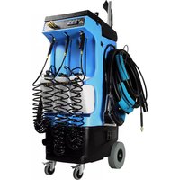
Prep Center 80-240 - Steam cleaner Mytee - Free user manual and instructions
Find the device manual for free Prep Center 80-240 Mytee in PDF.


| Product Type | Steam Cleaner |
| Model | Prep Center 80-240 |
| Brand | Mytee |
| Power Supply | 120V, 60Hz (estimated) |
| Power Consumption | 1500 W (estimated) |
| Water Tank Capacity | 3.5 gallons (13.2 L) (estimated) |
| Heating Element | Stainless steel, 1500 W (estimated) |
| Maximum Steam Temperature | 212°F (100°C) (estimated) |
| Steam Pressure | 60 psi (estimated) |
| Heat-up Time | Approx. 10 minutes (estimated) |
| Hose Length | 15 ft (4.6 m) (estimated) |
| Power Cord Length | 25 ft (7.6 m) (estimated) |
| Weight | 45 lbs (20.4 kg) (estimated) |
| Dimensions (L x W x H) | 24 x 16 x 32 inches (estimated) |
| Frame Material | Aluminum (estimated) |
| Wheels | 4 heavy-duty casters (estimated) |
| Accessories Included | Hand tool, floor tool, upholstery tool, crevice tool, 2 extension wands (estimated) |
| Maintenance | Regular descaling and filter cleaning (estimated) |
| Safety Features | Auto shut-off, pressure relief valve (estimated) |
| Warranty | 1-year limited warranty (estimated) |
Frequently Asked Questions - Prep Center 80-240 Mytee
User questions about Prep Center 80-240 Mytee
0 question about this device. Answer the ones you know or ask your own.
Ask a new question about this device
Download the instructions for your Steam cleaner in PDF format for free! Find your manual Prep Center 80-240 - Mytee and take your electronic device back in hand. On this page are published all the documents necessary for the use of your device. Prep Center 80-240 by Mytee.
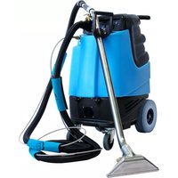
USER MANUAL Prep Center 80-240 Mytee
natural_image
Technical line drawing of a portable industrial machine with springs and wheels (no text or symbols)Dear Customer:
Congratulations on the purchase of your new Prep Center S ^™ . As technology continues to develop you can work confidently knowing that both Mytee Products and its employees are equally dedicated to developing with the industry and its advances.
Like any other piece of machinery or technology, the Prep Center S™ also requires proper maintenance and care to keep the product working over extended use. Neglecting your machine, abusing it or not operating it properly can void its warranty and prevent the machine from performing to the quality and standard you'd expect out of the Mytee Products line.
If you have any warranty concerns or questions, please review this manual thoroughly or do not hesitate to contact your distributor. If there are questions regarding maintenance, replacement, or ordering parts please contact an authorized Mytee Products Service Center. To see an updated list please visit our website at http://www.mytee.com/support/service-centers.
Before using your Mytee product, please read this manual thoroughly.
Sincerely,
Mytee Customer Care Dept.
Important Safety Information ....4
1 At a Glance 6.
1.1 - Technical Specifications 6....
1.2 - Included with the Prep Center S ^TM 6......
1.3 - Prep Center S™ Features 7....
1.4 - Prep Center S™ Switch Plate 8....
2 Machine Operation 9....
2.1 - Powering the Prep Center S™ 9....
2.2 - Connecting Vacuum and Solution Hoses 9....
2.3 - Connecting Shop Air Line 9....
2.4 - Filling the Solution Tank 9....
2.5 - Dry Vacuuming 9.
2.6 - Hot Water Extraction with the Prep Center S ^TM ...... 10
2.7 - Using the Blower Attachment 10....
2.8 - Using Auxiliary Chemical Bottles 10
2.9 - Emptying the Recovery Tank 10
2.10 - Storage 1
3 Troubleshooting....11
3.1 - Vacuum Troubleshooting 1
3.2 - Pump Troubleshooting 11
3.3 - Heater Troubleshooting 13
4 Available Accessories 14
Important Safety Information
Grounding Instructions
This machine must be grounded. If it should malfunction or breakdown, grounding provides a path of least resistance for electrical shock. This machine is equipped with a cord having an equipment-grounding conductor and grounding plug. The plug must be plugged into an appropriate outlet that is properly installed in accordance with all local code and ordinances. Do not remove ground pin; if missing, replace plug before use.

Improper installation of the equipment-grounding conductor can result in a risk of electric shock. Be sure to check with a qualified electrician or service person if you are in doubt as to whether the outlet is properly grounded. If the plug will not fit in the outlet do not modify either the plug nor the machine's cord, instead have a proper outlet installed by a qualified technician.
This machine is for use on a nominal 120-volt circuit and with a grounding plug similar to the one in Figure 1 below. If a proper outlet is not available, follow the illustrations of Figure 2 & 3 to install a temporary-grounding plug. This temporary work-around should be used only until a proper outlet (Figure 1) can be installed by a qualified electrician. When and if this type of adapter is employed, screw the adapter's extended tab into place with a metal screw. However, grounding adapters are not approved for use in Canada.
Again, be sure to check the grounding pin for damages and replace if necessary.
The Green, or Green-Yellow, wire in the cord is the grounding wire. When replacing a plug, this wire must be attached to only the grounding pin.
DO NOT use extension cords.
Please Note for America use only.

Parts and Service
Please contact a Mytee service personnel or Mytee authorized Service Center using Mytee original replacement parts and accessories for repairs are needing to be performed. When and if calling Mytee for support, please have your Model and Serial Number available for faster assistance.
Name Plate
The Model and Serial Number are located on the lower half of the back of the machine near the power plugs and will be required for ordering replacement parts. You can use the space provided on the front of this manual to note down both for future referencing.
Unpacking the Machine
When your new machine is delivered, please carefully inspect both the shipping carton and the machine for damages. If damage is evident, save both the shipping carton and machine so that the delivering carrier can inspect it. Contact the carrier immediately to file a freight claim if there has been any damage.
Caution and Warnings
Symbols
Mytee uses the symbols below to signal potentially dangerous conditions. Always read this information carefully and take the necessary steps to protect personnel and property.

Is used to warn of immediate hazards that will cause severe personal injury or death.

Is used to call attention to a situation that could cause severe personal injury.

Is used to call attention to a situation that could cause minor personal injury or damage to the machine or other property. When using an electrical appliance, basic precautions should always be followed, including the following: Read all instructions before using this machine. This product is intended for commercial use only.
Important Safety Information
To reduce the risk of fire, electrical shock, or injury:
-
Read all instructions before using equipment.
-
Use only as described in this manual. Use only manufacturer's recommended attachments.
-
Always unplug power cord from electrical outlet before attempting any adjustments or repairs.
-
Do not unplug by pulling on cord. To unplug, grasp the plug, not the cord.
-
Do not pull or carry by cord. Do not close a door on cord or pull cord around sharp edges or corners.
-
Do not run appliance over cord. Keep cord away from heated surfaces.
-
Do not use with damaged cord or plug. If cord is damaged, repair immediately.
-
Do not use outdoors or on wet surfaces and or standing water.
-
Always unplug or disconnect the appliance from power supply when not in use.
-
Do not allow to be used as a toy. Close attention is necessary when used by or near children.
-
Do not use in areas where flammable or combustible material may be present.
-
Do not leave the unit exposed to harsh weather elements. Temperatures below freezing may damage components and void warranty.
-
Use only the appropriate handles to move and lift unit. Do not use any other parts of this machine for this purpose.
-
Keep hair, loose clothing, fingers, and all parts of the body away from all openings and moving parts.
-
Use extra care when using on stairs.
-
To reduce the risk of fire or electric shock, do not use this machine with a solid-state speed control device.
-
The voltage and frequency indicated on the name plate must correspond to the wall receptacle supply voltage.
-
When cleaning and servicing the machine, local or national regulations may apply to the safe disposal of liquids which may contain: chemicals, grease, oil, acid, alkalines, or other dangerous liquids.
-
Do not leave operating unattended.
1 - At a Glance
1.1 - Technical Specifications 1.2 - Included with the Prep Center S™
| Body | Roto-molded polyethylene |
| Tanks | 12 gallon (approx.) |
| Vacuum | Single 3-stage low amp, 100 CFM, 130" water lift |
| Pump | Diaphragm pump, 120 PSI, 1.3 GPM |
| Heater | 1200 watt heating system - 210° maximum |
| Rear Wheels | 10" foam-filled |
| Locking Casters | 4" |
| Power Cord | Single 25' 12/3 |
| Amp Draw | 20 amps @ 115V 60Hz |
| Net Weight | |
| Product Dimensions | 31" x 19" x 53.5" |

8100 Vac/Sol Hose Assembly
8400P Air Lite™ Upholstery Tool

natural_image
Coiled black plastic hose or tube, no visible text or symbolsH294 Vacuum Hose

natural_image
Two identical U-shaped metal wire diagrams with no text or symbols2x H375 Hose Hangers w/ Hardware

PC86 Crevice Tool
natural_image
Black rubber brush tool with curved tip (no text or symbols visible)PC87 Claw Tool
A919 Exterior Drying Tool

P590 Cuties™ OD Safety Covers

One Pack
G008 Piglet™ Filters
1.3 - Prep Center S™ Features

- Pegs for tool storage
- Clear recovery tank lid
- Solution tank opening
- Storage tray
- Three spray nozzles with coiled hoses
- Three on-board chemical storage bottles
- Blower port
- 4" locking casters
-
Solution tank
-
10" foam-filled rear wheels
- 25' 12/3 power cord
- Air line input fitting
- Recovery tank drain
- Maintenance access latches
- Recovery tank
- Push handles
- Vacuum hose port
1 - At a Glance
1.4 - Prep Center S™ Switch Plate

- Vacuum switch
- Pump switch
-
Heater switch
-
Solution connection fitting
- Air line output fitting
2.1 - Powering the Prep Center S™

natural_image
Technical line drawing of a wheeled cart with a blue electrical outlet and cable, no text or symbols presentTo power the Prep Center S ^TM , plug the power cord into a grounded 20 amp outlet.
2.2 - Connecting Vacuum and Solution Hoses

natural_image
Technical diagram of a mechanical device with blue hoses and connectors (no text or symbols)Connect the vacuum hose via Cuff-Lynx™ connector to clear elbow on top of the machine. Simply twist the male Cuff-Lynx™ into the elbow. Connect the solution line to female solution quick connect fitting on the switch plate.
2.3 - Connecting Shop Air Line
Shop air input is located in the bottom-right corner of the rear of the machine.
Output is located on the switch plate.
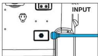

2.4 - Filling the Solution Tank

natural_image
Technical line drawing of a mechanical device with blue tubing and a water tap, no text or symbols presentFaucet Fill
The solution tank can be filled from a standard faucet or hose bib. Simply lift the Faucet Fill hose out of the tank and press it against the faucet. Turn on the faucet to allow water to flow into the tank.

natural_image
Technical line drawing of a mechanical device with a blue component and a blue plastic bag (no text or symbols)Bucket Fill
Fill up a bucket with water and pour into the solution tank through the opening on top of the machine. Add desired chemical according to manufacturer specifications.
2.5 - Dry Vacuuming IMPORTANT: DO NOT dry vacuum without a Piglet™ Filter in place on the strainer basket. This will cause damage to the vacuum motor.
- Attach a vacuum hose to the clear elbow.
- Switch on the vacuum and begin vacuuming.
- Replace the Piglet ^TM filter regularly.

2 - Machine Operation
2.6 - Hot Water Extraction with the Prep Center S™

To avoid a vapor lock, follow this procedure when turning on the machine for hot water extraction.
- Turn PUMP switch on. Pull the lever on the cleaning tool to release air in the line. Hold lever until a steady flow of water comes out of the tool.
- Turn on HEATER switch and wait a few minutes for water to heat up.
- Once water is heated, turn on VACUUM and begin cleaning.
2.7 - Using the Blower Attachment

natural_image
Technical line drawing of a mechanical device with a blue flexible hose attached to the lower arm (no text or symbols present)Attach vacuum hose via Cuff-Lynx™ adapter to the blower port on the front of the machine in the bottom-right corner. Switch on the VACUUM. The blower attachment uses the exhaust from the vacuum for drying.
2.8 - Using Auxiliary Chemical Bottles

natural_image
Technical illustration of a mechanical device with hoses and a spray gun emitting blue dashed lines (no text or symbols)Put desired chemical in the bottle(s) to be used. Connect shop air to the air line input quick connect in the bottom right corner of the rear of the machine. Once the bottle(s) are pressurized, chemical can be sprayed using the attached nozzles.
2.9 - Emptying the Recovery Tank

natural_image
Technical diagram of a mechanical device with internal components and fluid flow indicators (no text or symbols)Pull up on the drain valve handle on the rear of the machine to drain the recovery tank into a bucket or drain.
2.10 - Storage
When storing the Prep Center S ^™ , make sure all liquid is purged from the system and the tanks are drained. This is especially important in cold climates.
3.1 - Vacuum Troubleshooting
| Vacuum is not turning on. | |
| Possible Cause Solution | |
| Vacuum may not be getting power. | Check the electrical connections and the switch.Look for loose or damaged wires.To check the switch:Unbolt the switch plate.Take a picture of the layout of the wires or tagging the wires for future reference.Switch the wires from the vacuum switch with the wires from either the pump or heater switch. Turn on the pump or heater switch (whichever one you exchanged wires with). If the vacuum turns on, then you know the vacuum switch is bad. |
| Vacuum is not producing suction. | |
| Possible Causes Solutions | |
| Recovery tank is full. Empty | the recovery tank. |
| If the vacuum exhausts but there is no suction, then the hose from the recovery tank to the vacuum motor is disconnected. | Open the machine and find the hose running from the recovery tank to the vacuum motor. Check if it is disconnected. If so, reconnect it. If it has a leak, replace the hose (Part # PH627 if 1.5", PH628 if 2"). |
| Vacuum hose blockage (if there is no suction or exhaust). | Check for blockage in the hose, starting from the cleaning tool to the machine. |
| Clogged filter in vacuum tank. | Clean out filter regularly. |
| Drain valve/cap is loose and is causing air leakage. | Tighten the drain valve/cap. |
| Hose cuffs are loose and causing air leakage. | Tighten all hose cuffs regularly as may loosen over time. Use a glue to prevent cuffs from coming loose (optional). |
| Lid on tank is loose and is causing air leakage. | Make sure the lid is tight. |
| Vacuum blows water out the exhaust. | |
| Possible Causes Solutions | |
| Foam building up in the recovery tank. | Use a defoaming solution in the recovery tank. |
| There is a loud grinding noise coming from the vacuum. | |
| Possible Cause Solution | |
| Debris has been sucked into the vacuum motor chamber. Usually results from dry vacuuming. | Replace the vacuum motor. To avoid repeat problem, DO NOT dry vacuum with your extractor. |
Click here for more detailed information.
3.2 - Pump Troubleshooting
| Pump doesn’t turn on. | |
| Possible Causes Solutions | |
| Bad switch at control panel. | Unbolt the switch plate. We recommend taking a picture of the layout of the wires or tagging the wires for future reference. Switch the wires from the pump switch with the wires from either the vacuum or heater switch. Turn on the vacuum or heater switch (whichever one you exchanged wires with). If the pump turns on, the pump switch is bad. |
| Loose or disconnected wire. | Disconnect the power cord from the electrical outlet. Open up the machine and look for any loose or disconnected wires. Re-attach or replace wires. |
3 - Troubleshooting
| Pump runs but there is no spray. | |
| Possible Causes Solutions | |
| Blockage or kink somewhere in the line. | See chart on page 4 of the Diaphragm Pump Troubleshooting Guide to diagnose the location of the block-age. |
| Air is in the pump. Prime the | pump. |
| Remove QD off the machine and solution hose.Make sure that the three-prong clip on the inside of the threaded end is evenly aligned below the thread of the QD. | |
| On a new unit, the check valve between the pump and heater may hang up, causing the flow of water to be impeded or stop entirely. | Remove the check valve temporarily and check to see if the pump will flow water out of the pump outlet hose when the pump is turned on for a brief instant in order to verify cause.The remedy is to install a new check valve. Observe the proper orientation (flow direction) of the check valve.Tip: the check valve may be able to be temporarily returned to service by un-sticking the check valve poppet with manipulation of the poppet ball with a thin tool, like a straightened paperclip. Replace the check valve in unit assembly.NEVER OPERATE A UNIT WITHOUT A CHECK VALVE IN PLACE. |
| Pump runs for a second then shuts down. | |
| Possible Causes Solutions | |
| QD is pressure locked. Relieve pressure from behind the QD by pressing in the button inside the QD. | |
| Low PSI. | |
| Possible Causes Solutions | |
| The jet nozzle could be too large. | Replace the jet with one that has a smaller opening. |
| Pump doesn’t stop running. | |
| Possible Causes Solutions | |
| Leak somewhere in the line. | Disconnect the solution hose from the machine. If this causes the pump to stop running then the problem is outside the machine, either in the solution hose or tool. If it continues running on, open the machine and check for leaks. Repair the leak. If there are no leaks, run Mytee’s System MaintainerTM (Part # 3601) through the machine to clear blockages. |
| Cracks or vacuum leaks on inlet side of pump. | Make sure hoses are secured tightly. If the inlet side of the pump is cracked or damaged, replace the pump. |
| Seals have been degraded by chemical. | Install seal repair kit. |
| Debris blocking inlet filter or pump head. | Clean filter and/or pump head. |
| Pump trips circuit breaker when turned on. | |
| Possible Causes Solutions | |
| Short in power switch. Test by swapping vacuum and pump switch. If problem resolves, but vacuum begins tripping breaker, replace switch (Part #E515). | |
| Short in electrical harness. | Risk of electric shock. Do this at your own risk.Remove pump from circuit by attaching power leads together. If breaker still pops when switch is toggled, then there is a short to the ground in the circuit. Replace wires as needed. |
| Short in pump motor. If switch | and harness check is OK, the short may be in the pump motor. Replace pump. |
Click here for more detailed information.
3.3 - Heater Troubleshooting
| Heater is not heating water. | |
| Possible Causes Solutions | |
| Loose electrical connection. | Check all electrical connections, including power cord and harness. |
| Automatic sensor has failed, causing manual sensor to trip. | Reset the manual sensor button by pressing the small white and yellow button in the center of the sensor. If this works, but heater continues to trip the manual sensor, replace the automatic sensor (Part #E573) on the heater. |
| Heater element has failed. Check for continuity through the element by reading the amperage. If amps are low, only part of the element may be heating up – in this case, the element is damaged and needs to be replaced. | |
| Bad power switch. If the element, sensors, and wiring all check out okay, there may be a bad switch on the switch-plate. | |
| Running out of hot water too fast. | |
| Possible Causes Solutions | |
| Too much water flowing through the heater. | Remember, when using your machine, it is recommended you do one wet pass followed by two dry passes. This way you are not spraying as much and the hot water will last longer. |
| Jets being used are too large. | If your machine has a 1,000W or 1,200W heating system, make sure your cleaning tool has 0.02 jets. |
| Water in tank is very cold. If possible, fill your solution tank with warm water in order to shorten the amount of time it takes for the water to heat up. The pumps are usually rated for 140°F water. | |
| Heater has hard water buildup inside, leading to lost efficiency. | Run Mytee System Main-tainerTM (Part # 3601) through the machine regularly in order to clear hard water or chemical residue that can block water flow and reduce heating ability. See product label for instructions. |
| Unit has vapor locked and there is no water pumping out of the unit. | |
| Possible Cause Solution | |
| Turning on the heater before turning on the pump and priming the unit. | Turn off the heater and allow the unit to cool completely. When machine has cooled, turn on the pump first. Prime the unit by spraying solution out of the cleaning tool. Then, turn on the heater. |
Click here for more detailed information.
4 - Available Accessories
natural_image
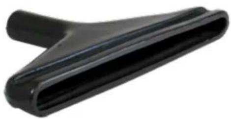
Black plastic mechanical component with tapered end (no text or symbols visible)PC88 Interior Drying Tool

G008 Piglet™ Filters - pack of 20
natural_image
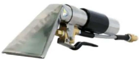
Close-up of a mechanical device with a metallic handle and brass fittings (no visible text or symbols)8400 4" Stainless Steel Upholstery Tool

natural_image
Close-up of a metallic tool with black and gold components, no visible text or symbols8700 Stainless Steel Crevice Tool
Notes

Mytee Products, Inc.
13655 Stowe Dr.
Poway, CA 92064
www.mytee.com
© 2019 Mytee Products, Inc.
Printed in the USA
- Dear Customer:
- Important Safety Information ....4
- At a Glance 6.
- Machine Operation 9....
- Troubleshooting....11
- Available Accessories 14
- Important Safety Information
- Grounding Instructions
- Parts and Service
- Name Plate
- Unpacking the Machine
- Caution and Warnings
- Symbols
- To reduce the risk of fire, electrical shock, or injury:
- - At a Glance
- - Technical Specifications 1.2 - Included with the Prep Center S™
- - Connecting Shop Air Line
- Faucet Fill
- Bucket Fill
- - Dry Vacuuming IMPORTANT: DO NOT dry vacuum without a Piglet™ Filter in place on the strainer basket. This will cause damage to the vacuum motor.
- - Machine Operation
- - Hot Water Extraction with the Prep Center S™
- - Using the Blower Attachment
- - Using Auxiliary Chemical Bottles
- - Emptying the Recovery Tank
- - Storage
- - Troubleshooting
- - Available Accessories
- Notes
Brand : Mytee
Model : Prep Center 80-240
Category : Steam cleaner