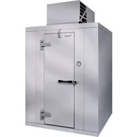
Polar Pak PX7-128-CT - Refrigerator Kolpak - Free user manual and instructions
Find the device manual for free Polar Pak PX7-128-CT Kolpak in PDF.


| Product Type | Refrigerator (Under Counter) |
| Dimensions (W x D x H) | 600 x 800 x 850 mm |
| Weight | 65 kg |
| Power Supply | 230V/50Hz |
| Capacity | 128 L |
| Cooling System | Forced air |
| Temperature Range | 0°C to 10°C |
| Defrost Type | Automatic |
| Door Type | Solid stainless steel |
| Shelves | 4 adjustable shelves |
| Interior Lighting | LED |
| Refrigerant | R290 |
| Energy Consumption | 0.8 kWh/24h |
| Noise Level | 45 dB(A) |
| Climate Class | 4 (30°C) |
| Installation Type | Freestanding |
| Maintenance | Periodic condenser coil cleaning |
| Cleaning | Use mild detergent and water |
| Safety Features | Door lock, temperature alarm |
| Spare Parts Availability | Contact Kolpak for genuine parts |
| Manufacturer | Kolpak |
Frequently Asked Questions - Polar Pak PX7-128-CT Kolpak
User questions about Polar Pak PX7-128-CT Kolpak
0 question about this device. Answer the ones you know or ask your own.
Ask a new question about this device
Download the instructions for your Refrigerator in PDF format for free! Find your manual Polar Pak PX7-128-CT - Kolpak and take your electronic device back in hand. On this page are published all the documents necessary for the use of your device. Polar Pak PX7-128-CT by Kolpak.
USER MANUAL Polar Pak PX7-128-CT Kolpak
Kolpak/RDI Refrigeration System Installation & Operation Manual


Welbilt
2915 Tennessee Avenue North
Parsons, TN 38363
Phone: 800-225-9916
www.welbilt.com
550001058-10
April 2017
Table of Contents
Safety Information ....3
Receiving Inspection....4
Locating and Mounting Condensing Units 4-6
Locating and Mounting Evaporator Coils 6-7
Wiring 8
Piping....8-13
Leak Test....14-15
Evacuation....15-16
Refrigerant Charging....16
Suction/Liquid Line Sizing Chart 17
Operational Start-Up 18-20
Compressor Superheat....21
Evaporator Superheat 22-23
Thermostat....24-28
Electric Defrost Timer....29
Maintenance 30
Troubleshooting Charts....31-33
ArcticFox Local Area Dashboard & Alarms (LDA): 34
ArcticFox LDA Kit....34
ArcticFox LDA Back Label 35
ArcticFox LDA Side View 35
ModBus Configuration....36-38
Installing The ArcticFox LDA: Option 1....39
Installing The ArcticFox LDA: Option 2....39
Installing The ArcticFox LDA: Option 3....40
Using the ArcticFox Flash Drive For Data Logging The ArcticFox LDA 40
Accessing The Local Dashboard....41-58
Evaporator Troubleshooting....59
Condensing Unit Troubleshooting 60-61
Wiring Diagrams 62-76
Condensing Unit 208-230/1/60....62
Condensing Unit 208-230/3/60....63
Condensing Unit 460/3/60....64
Condensing Unit Medium Temp (MZ) Scroll 208-230/1/60....65
Condensing Unit Medium Temp (MZ) Scroll 208-230/3/60....66
Condensing Unit Low Temp (LZ) Scroll 208-230/1/60 67
Refrigeration System Low Temp (LZ) Scroll 208-230/1/60 68
Condensing Unit Low Temp (LZ) Scroll 208-230/3/60....69
Refrigeration System Low Temp (LZ) Scroll 208-230/3/60 70
Air Defrost Evaporator 115/1/....71
Air Defrost Evaporator 208-230/60/1....72
Air Defrost with 2 Evaporators 115/1/60 73
Air Defrost with 2 Evaporators 208-230/60/1 74
Electric Defrost Evaporator 208-230/1/60....75
Electric Defrost with 2 Evaporators 208-230/1/60....76
System Start-Up Data Sheet....77-80
Warranty Information....81
General Safety Information
Read this manual carefully before beginning the installation and operation of the refrigeration system. Special attention is required to all sections identified with the following warning and caution notices provided in both English and French languages:
WARNING
Text in a Warning box alerts you to a potential personal injury situation. Read each Warning statement before proceeding and work carefully.
WARNING
Text in a Caution box alerts you to a situation in which you could damage the refrigeration system. Read each Caution statement before proceeding and work carefully.
CAUTION
Disregarding these special notices may result in personal injury and/or damage to the refrigeration system.
Safety Notices:
➢ Installation and maintenance/servicing are to be performed only by trained and qualified personnel familiar with commercial refrigeration systems. ➢ Ensure that all field wiring conforms to the equipment requirements and all applicable local and national codes. ➢ Disconnect all power sources before servicing the refrigeration equipment. Sheet metal and coil surfaces have sharp edges. Use appropriate protective gloves to prevent injury. ➢ Use appropriate eye protection during installation and servicing.
Receiving Inspection
Check the shipment carefully and compare to the bill of lading. Account for all items listed and inspect each container for damage. Carefully inspect for any concealed damage. Report any shortages or damages to the carrier, note on the bill of lading, and file a freight claim.
Damaged material cannot be returned to the manufacturer without prior approval. A Return Material Authorization (RMA) must be obtained. Contact a sales representative at 800-826-7036.
Locating and Mounting Condensing Unit
General Guidelines:
➢ Check the selected installation location to ensure that racks, braces, flooring, foundations, etc. are adequate to support the condensing unit weight. The installation location is clean, dry, and level. ➢ Locate away from corrosive and noise sensitive atmospheres. Use the condensing unit skid and base when moving the unit. Do not remove unit from skid until the unit is moved to the mounting location. Mount the condensing unit base to pads or structural rails using properly sized bolts through the unit base. Center of condensing unit needs to be properly supported.
General Guidelines - Condensing Unit Locating and Mounting (continued):

Correct
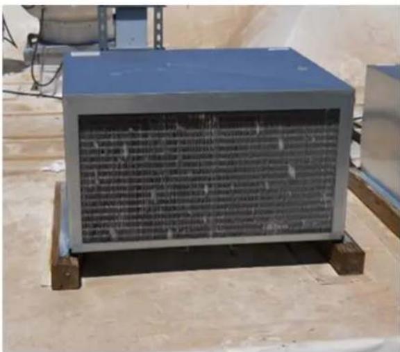
Incorrect
WARNING
Do not lift the condensing unit by the refrigerant tubing or components. These features will not support the condensing unit weight. Injury and unit damage may occur!
WARNING
Clearance Requirements:
Locate where there is a sufficient and unrestricted supply of clean ambient air. Locate where there is adequate space for the removal of the heated discharged air from the condensing unit area. Do not position multiple units so that discharge air from one unit is blowing into the condenser inlet air of the other unit. All sides of the unit should be positioned a minimum distance equal to the total width of the condensing unit away from any other unit, wall, or obstruction.
Clearance Requirements (continued):
Example of Multiple Units with Horizontal Airflow![graph TD A["24-inch"] -->|AIR FLOW| B["Building Wall (VIEWED FROM ABOVE)"] B -->|AIR FLOW| C["24-inch"] D["INTAKE AIR MINIMUM DISTANCE 24""] --> A E["MINIMUM DISTANCE 24""] --> B F["INTAKE AIR MINIMUM DISTANCE 24""] --> C](/content/2026/06/1248152/images/28b04be3ef1e7c77b3489e1d6db63f783794e892c3e0a14af18c31d4a40079a9.jpg)
CAUTION
Failure to observe clearance and air flow requirements will result in poor system performance and premature equipment failure!
CAUTION
Locating and Mounting Evaporator Coil
General Guidelines:
Do not place the evaporator above or close to door openings. This will help prevent potential icing problems. Allow a minimum clearance equal to or greater than the coil height on all sides of the coil for proper air flow and service access. Use the evaporator coil for a template to locate and drill the mounting holes (1/2" diameter). Place a 1" and a 1-5/8" washer on each nylon bolt and insert through the drilled mounting holes in the ceiling from the exterior of the walk-in ceiling panel.
General Guidelines - Locating and Mounting Evaporator Coil (continued):
NOTE: Nylon bolts are supplied to prevent thermal transfer between the exterior of the walk-in and the interior of the walk-in. Do not use metal bolts.
➢ Lift the evaporator coil until the nylon bolts extend through the mounting brackets. ➢ Install washers and secure with nuts. Tighten until the coil is firm against the ceiling. The evaporator coil must be level. Additional information is available in the installation manual supplied with the evaporator.
CAUTION
Failure to observe clearance and air flow requirements will result in poor system performance and premature equipment failure!
CAUTION
Wiring
All electrical connections and routing must comply with local and national codes. Do not modify the factory installed wiring without written factory approval. The field wiring must enter through the knockouts provided. Refer to the nameplate on the condensing or evaporator coil to determine the proper electrical power supply. Wire type should be of copper conductor only and properly sized to handle the electrical load. The unit and coil must be properly grounded. Condensing unit wiring diagrams are located inside this installation manual and attached inside the electrical box cover. Evaporator coil wiring diagrams are located inside this installation manual and inside the evaporator cover.
WARNING
All wiring must comply with local and national codes. Wiring must be performed only by a refrigeration technician or certified electrician. Failure to follow these guidelines may result in injury!
WARNING
Check all wiring connections, including factory terminals, before operation. Connections can become loose during shipment and installation.
CAUTION
General Requirements:
All refrigeration piping and components are to be installed in accordance with applicable local and national codes and in conformance with industry refrigeration guidelines to ensure proper operation of the refrigeration system. Only refrigeration grade copper tubing should be used. Long radius elbows should be used. Short radius elbows have points of excessive stress concentration and are subject to breaking at these points, do not use short radius elbows. Suction lines must be insulated with a minimum 3/4" thick insulation tubing to reduce heat pick-up.
Cleanliness:
Condensing units and evaporator coils are cleaned and dehydrated at the factory. The condensing unit must remain closed and pressurized until the piping is complete and final connections are ready to be made.
CAUTION
The maximum air exposure for dehydrated condensing units is 15 minutes. Systems exposed longer than 15 minutes must have the compressor oil and drier filter replaced. Leaving a system exposed to the atmosphere for more than 15 minutes can result in premature system failure.
CAUTION
Do not remove base mount valve covers until work is ready to be performed. Ensure that all refrigeration tubing is clean and dry prior to installation. Use only tubing cutters when trimming tubing to the proper length. Do not use saws to cut tubing.
CAUTION
The use of saws to cut tubing can contaminate the system with copper chips causing premature system failure.
CAUTION
Brazing joints require a dry inert gas, typically nitrogen, be passed through the lines at a low pressure to prevent scaling and oxidation. Use only silver solder brazing alloys. Minimize the amount of flux to prevent internal contamination. Flux only the male portion of the joint. Thoroughly clean fluxed joints after brazing.
CAUTION
Dry inert gas must be passed through the system while brazing to prevent scaling and oxidation. Scaling and oxides can clog refrigeration components resulting in system failure.
CAUTION
All tubing should be supported in at least two locations (near the end of each tubing run). Long runs will require additional support. As a guide, support 3/8" to 7/8" pipe every five feet, 1-1/8" to 1-3/8" every seven feet, and 1-5/8" to 2-1/8" every ten feet. Do not leave a corner unsupported when changing directions. Place supports within 2 feet of each direction change. Piping that is attached to a vibrating object (such as a compressor or compressor base) must be supported in a manner that will not restrict the movement of the vibrating object. Rigid mounting will fatigue the tubing causing refrigerant leaks.
Oil Traps:
To ensure proper oil return to the compressor, a P-type oil trap should be installed at the base of each suction riser of four feet or more. The suction trap must be the same size as the suction line. Additional traps are necessary for long vertical risers. Add a trap for each length of pipe (approximately 20 feet) to insure proper oil return. Suction lines must slope 1/4 inch per 10 feet toward the compressor. Install a suction line trap at the evaporator outlet if the suction line rises to a point higher than the connection on the evaporator.
CAUTION
Failure to properly install oil traps can prevent sufficient oil return to the compressor, resulting in premature compressor failure.
CAUTION
Pressure Regulating-Relief Valves:
WARNING
Do not defeat, cap, add piping to the outlet of the valve, or attempt to change the relief setting.
WARNING
Evaporator coil drain lines should be pitched a minimum of 1/2" per foot to allow proper drainage and exit the walk-in as quickly as possible. Insulate and seal the drain line where it passes through the wall. Copper drain line is required. Freezer compartment drain lines must have heat tape wrapped around the copper drain line and must have 3/4" thick insulation tubing. Do not locate drain line P-traps within the freezer space. Do not reduce the drain line size. Locate a drain line P-trap outside of the cooler space. Any outdoor P-traps exposed to low ambient temperatures should be wrapped with a drain line heater (provide 20 watts of heat per foot of drain line at 0°F, 30 watts per foot at -20°F). Freezer/cooler combo boxes can have one common drain line. However, there must be a P-trap located between the freezer evaporator and the cooler evaporator located inside the cooler compartment. The cooler compartment P-trap should be located between the cooler evaporator and the external drain location.

Pre-Charged Lines and Quick Connects:
Route the suction and liquid line sets between the condensing unit and evaporator coil following the piping guidelines identified in this manual. Remove the dust caps from the quick connect fittings and verify that the o-rings are intact. Wipe the coupling seals and threaded surfaces with a clean cloth to prevent contamination. Lubricate the threads and o-rings with Polyol Ester oil. Thread the coupling halves together by hand to ensure proper thread mating. Tighten with a wrench until the coupling bodies "bottom" or until there is definite resistance. Tighten an additional 1/4 turn to ensure proper brass-to-brass seating. Once the system is opened and pressurized, check each fitting for refrigerant leaks. If a leak is detected, tighten until the leak stops.


INCORRECT
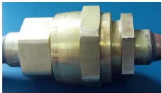
CORRECT
WARNING
Do not loosen and disconnect the quick connect fittings before reclaiming the refrigerant and depressurizing the system. Disconnecting a pressurized system can result in injury!
Pre-Charged Lines and Quick Connects (continued):
WARNING
Quick connects are for one time use only. Once disconnected, the coupling cannot be re-used. Refrigerant leaks will occur if the couplings are re-used resulting in poor system performance.
WARNING
Excess line set length should never be allowed to coil in the vertical position. Excess line length should be laid flat on its side.
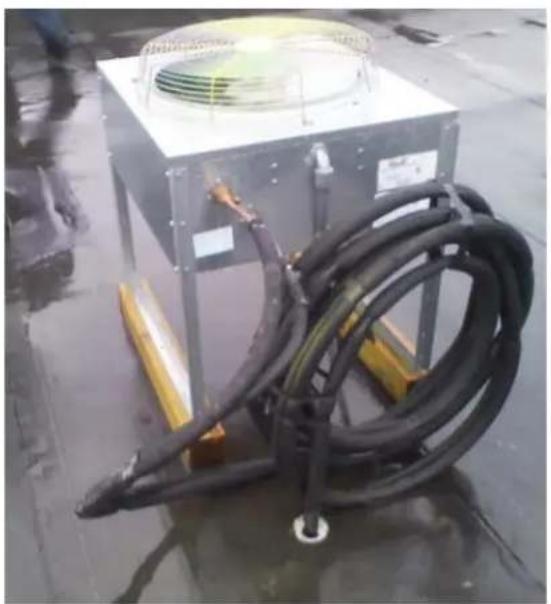
INCORRECT

CORRECT
Leak Testing
After all connections are complete the refrigeration system must be tested for leaks. Failure to perform a leak test can result in unsatisfactory system performance, additional servicing and service costs, and possible system failure. Leak test should be performed using an electronic leak detector. All joints and components, both factory and field installed, should be thoroughly inspected for leaks. The system installation must be leak free!
Leak Testing "PR" model systems:
- Open both the liquid and suction service valves. ➢ Ensure the solenoid valve is energized and open. ➢ Add 50 psi refrigerant, then pressurize with dry nitrogen to the low side test pressure identified on the unit rating label.
- Allow thirty minutes for refrigerant to reach all parts of the system. ➢ Check all joints and components with an electronic leak detector.
Leak Testing "PC" model systems:
Leave the service valves closed, the condensing unit is charged with refrigerant. - Ensure the solenoid valve is energized and open. ➢ Add 50 psi refrigerant, then pressurize with dry nitrogen to the low side test pressure identified on the unit rating label. - Allow thirty minutes for refrigerant to reach all parts of the system. ➢ Check all joints and components with an electronic leak detector.
Leak Testing "PCL" model systems:
- Open both the liquid and suction service valves. ➢ Ensure the solenoid valve is energized and open.
- Allow thirty minutes for refrigerant to reach all parts of the system. ➢ Check all joints and components with an electronic leak detector.
If a leak is detected, relieve the pressure and/or reclaim the refrigerant and repair the leak. If additional brazing is required, pass a dry inert gas (nitrogen) through the system to prevent contamination. Reference page 12 of this manual for leaks located at quick connect couplings. Retest the system as outlined above until no leaks are detected.
NOTE: R448 refrigerant is a blend and when leaks occur, it is unknown which refrigerant blend or how much of it has escaped. If R448 refrigerant is simply "topped off", the new blend mixture may affect proper performance of the system.
CAUTION
If a braze joint is detected leaking, dry inert gas must be passed through the system while repairing the joint to prevent scaling and oxidation. Scaling and oxides can clog refrigeration components resulting in system failure.
CAUTION
Always use the system specified refrigerant when pressuring to perform a leak test.
CAUTION
Evacuation of the refrigeration system is necessary to remove all air and moisture from the system. A reliable rotary vacuum pump with an accurate deep vacuum gauge is recommended. Do not use the system compressor as a vacuum pump and do not operate the compressor while the system is under vacuum.
Evacuation of "PR" model systems:
➢ Open both the liquid and suction service valves. ➢ Ensure the solenoid valve is energized and open. Connect vacuum pump to the liquid and suction service valves located on the condensing unit. ➢ Evacuate the system to 250 microns and maintain for a minimum of 4 hours. ➢ Perform a vacuum decay test for a minimum of ten minutes to ensure the system is leak free and dry.
Evacuation of "PC" model systems:
Leave the service valves closed, the condensing unit has been evacuated and is charged with refrigerant. ➢ Ensure the solenoid valve is energized and open. Connect vacuum pump to the liquid and suction service valves located on the condensing unit. ➢ Evacuate the system to 250 microns and maintain for a minimum of 4 hours. ➢ Perform a vacuum decay test for a minimum of ten minutes to ensure the system is leak free and dry.
Evacuation of "PCL" model systems:
- "PCL" systems do not require evacuation.
CAUTION
Do not use the system compressor to evacuate the system. Do not start the compressor while the system is under vacuum. This may damage the compressor and cause premature system failure.
CAUTION
Refrigerant Charging
The refrigerant charge should be added to the system through the liquid line service valve located on the condensing unit. Do not charge liquid refrigerant into the suction service valve! The initial charge should be determined by weight and sight glass indication. Start the system. If the condensing temperature is 105°F or greater, charge the system until the sight glass clears. If the condensing unit temperature is below 105°F, reduce the condenser face surface area to raise the discharge pressures above 105°F and to charge to a clear sight glass. Return to a full condenser face area when charging is complete.
NOTE: PC & PCL refrigerant charge amounts are based on average ambient operating temperatures across the United States. Any refrigerant amount added or removed based on ambient operating temperatures is considered part of normal maintenance and is not covered under warranty.
CAUTION
Do not charge liquid refrigerant into the suction service valve located on the condensing unit. Do not overcharge the system. These conditions can permit liquid refrigerant to enter the compressor and cause damage to internal components resulting in premature system failure.
CAUTION
* NOTES: 1. Sizes that are highlighted indicate maximum suction line sizes that should be used for risers. Riser size should not exceed horizontal size. Properly placed suction traps must also be used for adequate oil return. All sizes shown are for O.D. Type L copper tubing. 2. Suction line sizes selected at pressure drop equivalent to 2°F. Reduce estimate of system capacity accordingly. 3. Recommended liquid line size may increase with reverse cycle hot gas systems. 4. If system load drops below 40% of design, consideration to installing double suction risers should be made.
Operational Start-Up
The first 2 – 4 hours of operation after initial start-up is a critical time. Do not just start the system and leave. Pressure values, compressor and evaporator superheat, and inspecting for excessive vibrations and loose connections are some of checks that must be performed prior to leaving the system.
Pre-Start Checks:
▶ Verify that all service valves are fully open. ➢ Ensure that all refrigerant and electrical connections are tight. ➢ Verify that the wiring and piping is properly routed and secured. The compressor mounting bolts are properly adjusted (see compressor mounts on page 18). All fan motors and mounting brackets are tight. The condensing unit base and evaporator coil are properly secured.
Compressor Mounts:
Hermetic Compressors – hermetic compressor springs are mounted internally; check the compressor mounting bolts to ensure the nuts have not become loose during shipment.
Semi-Hermetic Compressors – most semi-hermetic compressors have external spring mounts and are factory assembled. The following actions are required once the condensing unit is installed and before system start-up:
Loosen the upper mounting nuts. Remove the spring steel clips from the mounting springs. Retighten the upper mounting nuts until the compressor can float on the springs approximately 1/16" between the mounting nut and rubber grommet.
Compressor Mounts (continued):
CAUTION
Failure to ensure the compressor mounts are properly tightened can result in fatigue to the system piping causing leaks and poor system performance.
CAUTION
Do not start the system while in a vacuum. Do not leave the system unattended until normal operating conditions are achieved.
CAUTION
Start-Up Procedure (continued):
Operate the system for a minimum of two hours and perform checks of the following:
Check the compressor discharge and suction pressures to ensure they are in the normal operating range. Check the liquid line sight glass for proper refrigerant charge (based off of 105°F condenser coil).
Monitor the compressor oil level (semi-hermetic compressors), add oil as necessary to keep the level at 3/4 sight glass when idle and 1/2 sight glass when running.
Check the voltage and amperage at the compressor terminals. Voltage must be within +10% or -5% of the rating indicated on the condensing unit name plate. On three phase compressors, verify there is a balanced load. Check all fans on the evaporator coil and condensing unit to be sure they are operational and turning in the correct direction. Check the piping and electrical connections for vibration. Add supports and strapping if needed. Check the crankcase heater operation (if equipped). Set the defrost control time and verify the defrost initiation settings. See pages 28-30 for additional details. Set temperature control to desired temperature range. Check the compressor and evaporator superheat (reference pages 21-23).
After all system checks have been checked, properly adjusted, and verified, replace all Schrader caps, service valve caps, electrical box covers, housings, etc. File a copy of this manual for future reference.
CAUTION
Failure to check and properly adjust compressor superheat can result in premature system failure.
Compressor Superheat:
Compressor superheat is a critical value that must be checked. Check the compressor superheat as follows:
- Determine the suction pressure at the suction service valve of the compressor.
- Determine the saturation temperature at the observed suction pressure using refrigeration pressure temperature tables.
- Measure the suction line temperature 6 -10 inches away from the compressor.
- Subtract the saturation temperature (step 2) from the measured temperature (step 3). The difference is the superheat of suction gas.
A low suction superheat can cause liquid to return to the compressor. This will cause dilution of the oil and eventual failure of the bearings, rings and valves. A high suction superheat will cause excessive discharge temperatures, which cause a breakdown of the oil. This causes piston ring wear, and piston and cylinder wall damage. System capacity decreases as the suction superheat increases. For maximum system capacity, keep the suction superheat as low as practical. Copeland requires a minimum compressor superheat of 20° F; however, to improve compressor life, 25° F to 40° F is preferred. Adjust the expansion valve at the evaporator when adjustments to the suction superheat are necessary. Refer to “Evaporator Superheat” on the next 2 pages for more information.

Evaporator Superheat:
Check the evaporator superheat once the walk-in has reached the desired temperature. Generally, systems with a design temperature drop of 10° F should have an evaporator superheat value of 6°-10° F on freezers and 8°-12° F on coolers for maximum efficiency.
To determine the evaporator superheat:
- Measure the suction pressure at the evaporator outlet.
- Convert the pressure to saturation temperature referencing a temperature-pressure chart.
- Measure the temperature of the suction line at the expansion valve bulb. Ensure the bulb is mounted at the correct location on the suction tube.
- Subtract the saturation temperature reading (step 2) from the measured temperature (step 3). The difference is the evaporator superheat.
Determining Evaporator Superheat
CAUTION
Minimum compressor superheat of 20°F may override these recommendations on systems with short line runs.
CAUTION
The condensing unit must have the discharge pressure above the equivalent 105°F condensing pressure (reference refrigerant charging on page 16).
Evaporator Superheat (continued):
CAUTION
Correct location and full contact of the expansion valve bulb is extremely important for proper system performance.
CAUTION
P/N 550005663 is used on all Air Defrost model evaporators and features a built in Air Defrost time clock. The default defrost settings are every 6 hours for 30 minutes. See pages 27-28 for default and custom defrost setting instructions.
P/N 550005664 is used on all Electric defrost model evaporators. See page 29 for Electric Defroster Timer setting instructions.
NOTE: The 550005664 display will be blank during the electric defrost cycle.
Thermostats (continued)


Red Light - Not used
Yellow Light - Non-critical alarm (system running)
Green Light - System running
Green Flashing - System waiting on minimum on/off timer to start/stop
- Access Setpoint mode by pressing and holding the ENTER button until ts (Temperature setpoint) displays on the screen
- Use the ▲ up and ▼ down arrows to scroll through the available setpoints
- Press ENTER to view the current setting
- Use the ▲ up and ▼ down arrows to change the setpoint
- Press and hold the ENTER button to confirm each setpoint change
- Press the BACK button to escape
Thermostats (continued)
Setpoints
tS = Temperature setpoint
diF = Differential
CSH = Maximum compressor starts/stops
dPd = Defrost per day
tod = time of day (only used when custom defrost is selected)
dFt = Defrost time
HAO = High Alarm Offset
LAO = Low Alarm Offset
tAd = Temperature Alarm Delay
Adr = Mod Bus Address
Unt = Units for temperature display (FAH or CEL)
Basic Setpoints
| Setpoint | Description | Minimum | 550005663Default | 550005664Default | Maximum |
| tS | Temperature Setpoint | -50°F (-45°C) | 35°F | 10°F | 100°F (38°C) |
| diF | Differential | 1°F | 3.5°F | 3.5°F | 30°F |
| CSH | Maximum Compressor Starts/Hour | 5 (Off)* | 0 (off) | 0 (off) | 10 |
| dPd | Defrost Per Day | 0 | 4 | 0 | 12, CUS** |
| dFt | Defrost Time | 0 min | 30 min | 0 min | 720 min |
| HAO | High Alarm Offset | 1°F | 10°F | 10°F | 10°F |
| LAO | Low Alarm Offset | 1°F | 5°F | 5°F | 10°F |
| tAd | Temp Alarm Delay | 1 min | 60 min | 60 min | 180 min |
| Adr | Mod Bus Address | 1 | 1 | 1 | 247 |
| Unt | Units for Temp Display | FAH | FAH | FAH | CEL |
*Selecting fewer than 5 compressor starts per hour results in the starts per hour feature being turned off. The compressor will then function on temperature only. ** Selecting CUS (custom) unlocks 12 tod (time of day) defrost setpoints.
Thermostats (continued)
Custom tod (Time of Day) Defrost Setpoints
| Setpoint | Description | Minimum | Default | Maximum |
| tod Time of Day 0.0 12.0 23.5 | ||||
| d1 Start time of day #1 0.0 dis (disabled) 23,dis (disabled) | ||||
| d2 | Start time of day #2 | 0.0 | dis | 23,dis |
| d3 | Start time of day #3 | 0.0 | dis | 23,dis |
| d4 | Start time of day #4 | 0.0 | dis | 23,dis |
| d5 | Start time of day #5 | 0.0 | dis | 23,dis |
| d6 | Start time of day #6 | 0.0 | dis | 23,dis |
| d7 | Start time of day #7 | 0.0 | dis | 23,dis |
| d8 | Start time of day #8 | 0.0 | dis | 23,dis |
| d9 | Start time of day #9 | 0.0 | dis | 23,dis |
| d10 | Start time of day #10 | 0.0 | dis | 23,dis |
| d11 | Start time of day #11 | 0.0 | dis | 23,dis |
| d12 | Start time of day #12 | 0.0 | dis | 23,dis |
Note: The time of day defrost setting uses military time. The first 2 digits are the hour and the 1 digit after the decimal is the minutes.
Thermostats (continued)
Custom Defrost Setup
Custom Defrost Setup
The following steps will guide you through the setup of the custom defrost feature.
Abbreviations:
CUS = custom
d1 = custom defrost 1
diS = disabled
ts = temperature setpoint
tod = time of day

STEP 1
Press and hold the ENTER button, tS is displayed on the LEDs

STEP 2
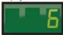
Press the ▲ up arrow until dPd is displayed,

then press ENTER, 6 (default) will be displayed.
STEP 3
Press the ▲ up arrow until CUS is displayed.

Press and hold the ENTER button for 3 seconds until the dPd is displayed.

STEP 4
Press the ▲ up arrow until tod (time of day) is displayed,
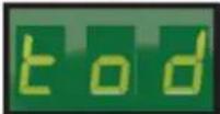
then press

Use the ▲ up arrow and ▼ down arrow to set the time.
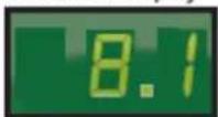
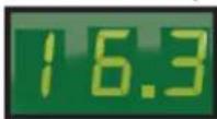
Note: The time is displayed in military time (24-hr clock) The 1st 2 digits are the hour. The minutes are after the decimal. Since there are only 3 digits, the time will be set to the nearest 10 minutes. See examples below.
Examples:
8:10 am would be 8.1 on the controller's display
4:32 pm would be 16.3 on the controller's display.
After the time is set, press and hold the ENTER button for 3 seconds, until tod is displayed
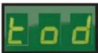
STEP 5
Press the ▲ up arrow to display Defrost 1 (d1).
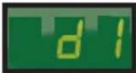
To set the first defrost, press ENTER button.
diS (disabled) will be displayed.
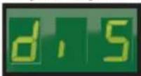
Use the ▼ down arrow to set the defrost time.
Note: Defrost times may only be set on the hour.
Example:
2:00 am would be 2
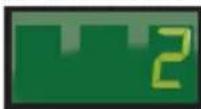
Once the correct time is displayed, press and hold the ENTER button until d1 is displayed.

STEP 6
Repeat steps as necessary for d2 to d12.


STEP 7
Press the BACK button to save settings, and return to the main screen (room temp will be displayed).
Electric Defrost Timer:
ELECTRIC DEFROST TIMER![graph TD A["Clock with 10/2/3/4/5/6/7/8/9/10/11/12/13/14/15/16/17/18/19/20/21"] --> B["Release Solenoid"] B --> C["Molecular structure with labeled positions 1-4"] C --> D["F 3 1 2 4 N X"] C --> E["X"]](/content/2026/06/1248152/images/a12afc02c4efa55d86104b4029b5ba2df8dee8d599828a09ddd81769feaf8e1c.jpg)
Electric Defrost Time Clock Instructions:
Instructions for setting the timer is located on the inside cover of the time clock. The defrost timer clock must be set to the correct time at initial start-up and after any power interruptions. Set the clock by rotating the clock face until the correct time is at the arrow on the face of the timer. The switch is programmed by pushing the captive trippers to the inner ring for the entire period the load is to be turned "ON". When a tripper is pushed to the outside, the switch is in the "DEFROST" position. Each defrost tripper represents 15 minutes of defrost time. The timer is factory set for four defrost cycles daily: 4:00AM, 10:00AM, 4:00PM, and 10:00PM. Each defrost cycle is programmed for 45 minutes duration. The defrost times may be changed to initiate at periods of low activity (trippers pushed out will close contacts to terminals 1 & 3).
Note: If the defrost termination thermostat fails to close, the fail-safe setting on the timer will terminate the defrost cycle. The timer starts the defrost cycle automatically at the predetermined times. A setting of two to four defrost cycles per day is typical. For heavier frost loads, additional cycles may be required.
When the defrost cycle begins:
- Switch 2 to 4 opens in the time clock, breaking the circuit to the room thermostat, liquid line solenoid, and evaporator fan motors. This allows the compressor to pump down and shut off. Simultaneously, switch 1 to 3 closes in the timer, energizing the defrost heaters.
- The heaters increase the coil temperatures above 32°F, melting the frost off the coil.
- When the coil warms to approximately 55°F, the defrost termination thermostat closes and energizes the switching solenoid in the timer. At this time, switch 1 to 3 in the timer opens, terminating the defrost heaters. Simultaneously, switch 2 to 4 closes in the time clock, energizing the temperature control circuit.
- Suction pressure rises, the low pressure control closes, and the compressor starts.
- The fan relay closes when the coil temperature reaches approximately 30°F. This energizes the fan motors.
- The system operates in the refrigeration cycle until another defrost cycle is initiated by the timer.
Maintenance
Maintenance Chart
| Area | Task | Frequency |
| Evaporator | Check for proper defrosting | Monthly |
| Clean the coil and drain pan | Every 6 months | |
| Check for proper drainage | ||
| Condenser | Inspect /clean the coil if the air supply is near polluting sources (such as cooking appliances) | Monthly |
| Clean the coil surface | Every 3 months | |
| General | Check/tighten all electrical connections | Every 6 months |
| Check all wiring and insulators | ||
| Check contactor for proper operation and contact point deterioration | ||
| Check all fan motors | ||
| Tighten fan set screws, and motor mount nuts and bolts | ||
| For semi-hermetics, check the oil level in the system | ||
| Check the operation of the control system | ||
| Make certain all safety controls are operating properly | ||
| Check operation of the drain line heater and examine for cuts and abrasions | ||
| Check/tighten all mechanical/flare connections |
CAUTION
Failure to keep the condenser coil clean will result in reduced airflow through the condenser, resulting in poor system performance and premature compressor failure.
CAUTION
Polyol Ester (POE) Lubricants:
Polyol Ester (POE) lubricants quickly absorb moisture from the ambient surroundings. POE lubricants absorb moisture more rapidly and in greater quantity than conventional mineral oils. Because moisture levels greater than 100 PPM will result in system corrosion and component failure, it is essential that system exposure to ambient conditions be kept to a minimum.
If a system is left open to the atmosphere for more than 15 minutes, the liquid line drier and compressor oil must be replaced. Drain at least 95% of the oil from the compressor suction port. Measure the amount of removed oil, and replace it with exactly the same amount of new POE oil. Mobil EAL™ ARCTIC 22 CC is the preferred Polyol Ester
Polyol Ester (POE) Lubricants (continued):
lubricant because of its particular additives. ICI Emkarate RL 32S is an acceptable alternative when the Mobil is not available. These POE lubricants must be used with HFC refrigerants. Lubricants are packaged in specially designed, sealed containers. Once opened, use the lubricant immediately. Properly dispose of any unused lubricant.
Troubleshooting Charts
Evaporator Troubleshooting Chart:
| Problem | Possible Cause | Corrective Action |
| Fan(s) will not operate. | Main switch open | Close switch |
| Blown fuse(s) | Replace fuse(s). Check for short circuits or overload conditions. | |
| Defective motor | Replace motor. | |
| Defective timer or defrost thermostat | Replace defective component. | |
| Unit in defrost cycle | Wait for completion of cycle. | |
| Walk-in temperature too high. | Thermostat set too high | Adjust thermostat. |
| Superheat too high | Adjust thermal expansion valve. | |
| System low on refrigerant | Locate and repair leak, recover, evacuate and recharge. | |
| Coil iced up Manually defrost coil. | Check defrost controls. | |
| Ice accumulating on ceiling around evaporator and/or on fan guards, venturi, or blades. | Defrost duration is too long | Adjust defrost termination thermostat (if adjustable). |
| Fan delay not delaying fans after defrost period | Replace defective defrost thermostat. | |
| Defective defrost thermostat or timer | Replace defective component. | |
| Too many defrost cycles per day | Reduce number of defrost cycles per day. | |
| Frost on coil after defrost cycle. | Coil temperature not getting above freezing point during defrost | Check heater operation |
| Not enough defrost cycles per day | Adjust timer for more defrost cycles per day | |
| Defrost cycle too short Adjust timer | for longer cycle, check defrost thermostat mounting | |
| Defective timer or defrost thermostat | Replace defective component. | |
| Ice accumulating in drain pan. | Defective heater | Replace heater. |
| Unit not pitched properly | Check and adjust. | |
| Drain line plugged | Clean drain line. | |
| Defective drain line heater | Replace heater. | |
| Defective timer or thermostat | Replace defective component. |
Condensing Unit Troubleshooting Chart:
| Problem | Possible Cause | Corrective Action |
| Compressor will not run. | Main switch open | Close switch |
| Fuse blown | Check electrical circuits and motor winding for shorts or grounds. Investigate for possible overloading. Replace fuse after fault is corrected. | |
| Thermal overloads tripped | Overloads are automatically reset. Check unit closely when unit comes back on line. | |
| Defective contactor or coil | Repair or replace | |
| System shut down by safety devices | Determine type and cause of shutdown and correct | |
| No cooling required | None. Wait until cooling is required. | |
| Liquid line solenoid will not open. | Repair or replace coil. | |
| Low pressure switch will not close. | Replace switch | |
| Motor electrical trouble | Check motor for open windings or short circuit. | |
| Loose wiring | Check all wire junctions. Tighten all terminal screws. | |
| Compressor noisy or vibrating | Flooding of refrigerant into crankcase | Check superheat setting of expansion valve |
| Improper pipe support | Relocate or add hangers | |
| Worn compressor | Replace compressor | |
| High discharge pressure | Non-condensable in system | Recover, evacuate and charge |
| System overcharged with refrigerant | Remove excess charge | |
| Discharge shut-off valve partially closed | Open valve | |
| Fan not running | Check electrical circuit or replace defective fan motor | |
| Insufficient condenser air supply | Check for cause and correct | |
| Dirty condenser coil | Clean coil | |
| Low discharge pressure | Faulty head pressure control | Check head pressure control operation. |
| Suction shut-off valve partially closed | Open valve | |
| Insufficient refrigerant in system | Locate and repair leak, recover, evacuate and recharge | |
| Low suction pressure | Check for proper refrigerant charge | |
| High suction pressure | Excessive load | Reduce load or add additional equipment |
| Expansion valve overfeeding | Secure and insulate TXV bulb or if required adjust superheat. | |
| Low suction pressure | Lack of refrigerant | Locate and repair leak, recover, evacuate and charge. |
| Evaporator dirty or iced | Clean | |
| Clogged liquid line or suction line filter-drier | Replace filter-drier | |
| Expansion valve malfunctioning | Check and reset for proper superheat | |
| Condensing temperature too low | Check head pressure control | |
| Improper TXV | Check for proper sizing | |
| Compressor loses oil | Lack of refrigerant | Locate and repair leak, recover, evacuate and recharge |
| Excessive compression ring blow-by | Replace compressor | |
| Refrigerant flood back | Maintain proper superheat at compressor | |
| Improper piping or traps | Correct piping | |
| Compressor thermal protector switch open | Operating beyond design | Add facilities so that operating conditions are within allowable limits |
| Discharge valve partially shut | Open valve | |
| Dirty condenser coil | Clean coil | |
| Overcharged system | Correct charge |
Notes:
ArcticFox Local Area Dashboard & Alarms (LDA):
- When the LDA is connected to the same network as ArcticFox controllers, it immediately and automatically scans and finds all ArcticFox controllers – Ethernet or Serial-ModBus.
- Serve as a Permanent WiFi Service Tool
- Display a Local Area Dashboard showing controllers connected to the customer's network
- Connect controllers to ArcticFox SmartAccess customer portal without requiring controller upgrades
- Send Email Alarms to multiple email recipients
- View Serial devices in a webpage, make changes to setpoints, and receive alerts via email or text message • 366-day datalogging when used with the ArcticFox Flash Drive
- Wirelessly tether to the local network (Wirelessly connect a controller to existing WiFi.)
- The LDA allows customers to locally view all of their controllers in a single view, without a recurring fee. And, additionally, enables customers to access their controllers over the Internet, by functioning as a conduit to ArcticFox SmartAccess (available for a nominal monthly charge.)
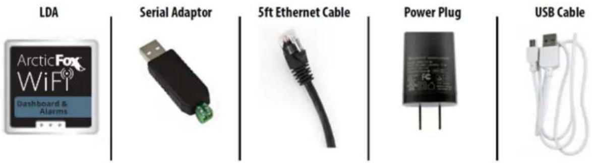
ArcticFox LDA Kit includes the LDA & Accessories:
LDA Back Label:
LDA Side View: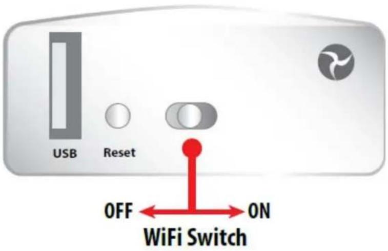
ModBus Configuration – First Installation Of ModBus Devices On LDA.
Step 1 – Daisy chain connections on controllers.

Step 2 – Finish wiring connection at USB adapter.
Do not plug into LDA or power on LDA
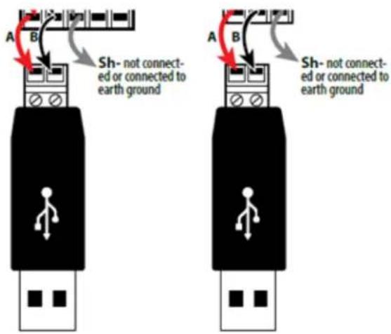
Step 3 – Power on controllers.
Step 4 – Change ModBus address on each controller.

Each controller's ModBus address must be unique. Available addresses are 2-247.
Press and hold the ENTER button to access the Setpoints menu.
tS is displayed.

Then use the ▼ arrow until you see Adr (Address).

Press ENTER and the current address is displayed (default =1)
Change the address by pressing the ▲ or ▼ arrow to change the value. Use the button to move to the next digit. Available addresses are 2-247.
When address is set to the preferred value (ex. 123), press and hold ENTER for 3 seconds to save the address.

Example
The controller will return to the Adr screen when the setting is saved.

The setting change can be verified by pressing the ENTER button.
To exit, press the BACK button several times.
Step 5 – Plug the USB adapter into the LDA.

Step 6 – Power the LDA.
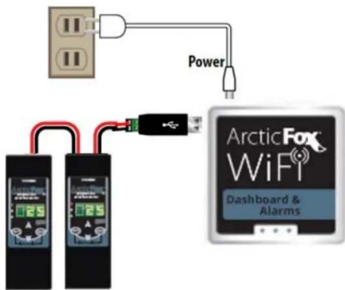
Installing the LDA: Option 1 – Connecting using the LDA as a permanent WiFi service tool.
Note: Each device must have a separate/unique Modbus address.
Plug power cable into the LDA and the other end into an electrical outlet. The unit will power on automatically.
![graph TD A["Power"] --> B["ArcticFox WiFi Dashboard & Alarms"] C["Two connected devices"] --> D["USB to WiFi"] D --> E["Connect wirelessly to the LDA Network"] style A fill:#f9f,stroke:#333 style B fill:#ccf,stroke:#333 style C fill:#cfc,stroke:#333 style D fill:#fcc,stroke:#333 style E fill:#cff,st…](/content/2026/06/1248152/images/ce60b4ef13eea0ace49cb66b0ea90952946cd887358292d0b36ce9917243a44c.jpg)
Installing the LDA: Option 2 – Direct connection to PC via cable or WiFi. Note: Each device must have a separate/unique Modbus address.
![graph TD A["Laptop"] --> B["LAN"] B --> C["Plug power cable into the LDA and the other end into an electrical outlet. The unit will power on automatically."] B --> D["Power"] D --> E["Arctic Fox WiFi Dashboard & Alarms"] E --> F["Connect wirelessly to the LDA Network"] F --> G["WiFi to PC/Laptop, Ta…](/content/2026/06/1248152/images/b1d5738b37307436a41a1619e531f155b86066c9ea27243f4fa0ae16cd5ea392.jpg)
Installing the LDA: Option 3 – Direct connection to PC via cable without WiFi. Note: Each device must have a separate/unique Modbus address.
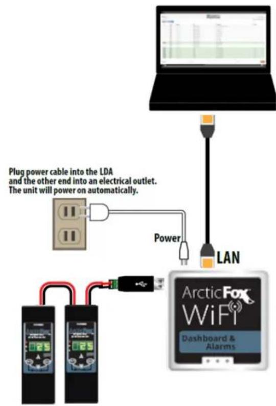
Using the Flash Drive for data logging the LDA.
- Regardless of how the LDA is connected to the network, if the Flash Drive is used for data logging, the USB Hub is connected first. Then the Flash Drive, and the daisy-chained Serial-Modbus controllers, are connected to the ports in the USB Hub.
Flash Drive Kit


Accessing the local dashboard.
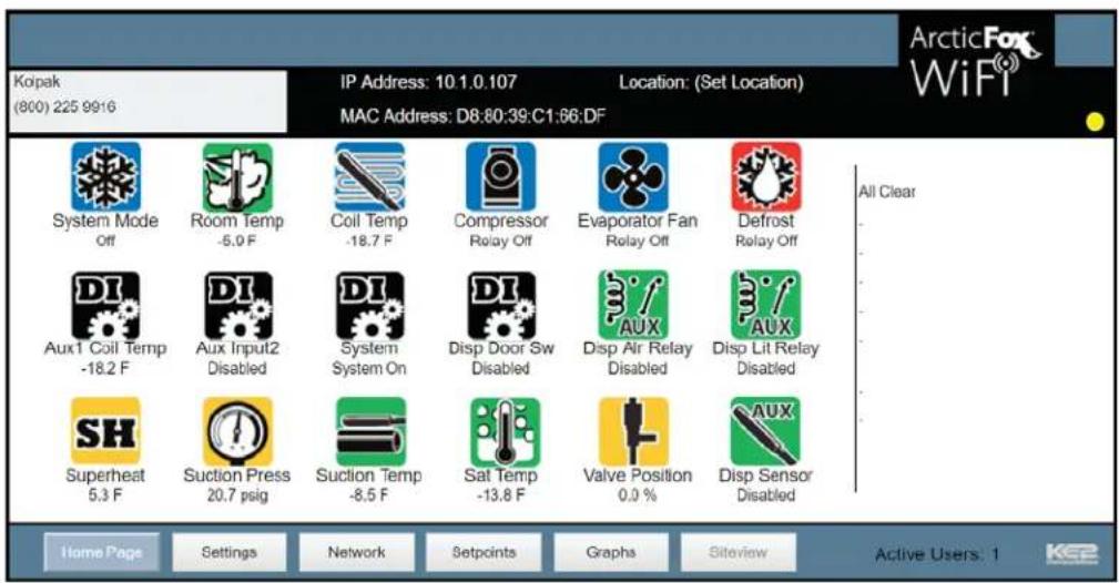
- To access the LDA, connect to the same network as the device. Since it is an Ethernet device, speaking TCP/IP, users can connect to it by simply launching their preferred web browser, and typing in the address bar: https://aflda

https://aflda/
- This brings the user to their local dashboard. Once connected to the dashboard, the user will immediately see up to 10 displayed controllers. For controllers on the network, simply click on the IP address of the controller, to immediately connect to that controller's home page.

- The user's web browser will launch a new tab, and open the controllers MasterView, giving immediate access to view the controller, as well as make changes.
Connecting the LDA to the internet:
You have 2 options when connecting the LDA to the internet – either hardwire the WAN port to the customer switch/router, or tethering to WiFi.
When in the manage page, click on the "Advanced" tab.
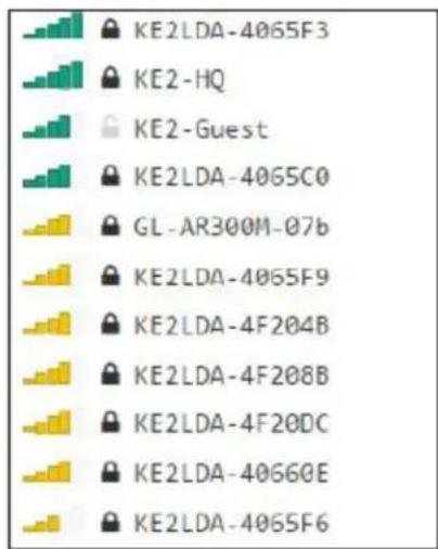
Clicking anywhere in the Wi-Fi box forces a scan for available wireless networks.
Kolpak recommends connecting to the LDA via the LAN port. As the warning states you could be disconnected from Wi-Fi during the scan.

Pick the appropriate WiFi profile to connect.
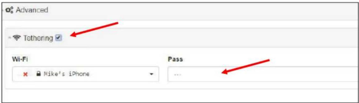
Enter the password, then check the Tethering box.
Allowing Kolpak to Remote Access:
It is often beneficial to allow Kolpak Technical Support to remotely access the portal to help assist with any problems.

Manage Email Alerts - Designed to simplify email notifications, the LDA provides:
- Single-point to enter email information, up to 10 controllers.
- Manage the email addresses receiving alerts.
- Set who the email is from.
- Elect to either use ArcticFox email server, or a customer provided server.
Navigate to the Management screen.

The Alerts section is at the bottom of the listed options. To enable the functionality, click the box next to the alerts.

For questions pertaining to the Alerts, click on the ? near the top right on the screen.
![Alerts Transqun From Subject xklv.stlerey@k203ms.cse,ryan.klslterey@k203ms.cse [iso.alerey@k203ms.net] [ Alarm 1 ] [ Alarm 2 ] [ xLR Sites - Service Description ] [ MSDA.xLR No SMTP Advanced Text Clear](/content/2026/06/1248152/images/f38d06ec1b9f35da236c3cb4913bce9f6f523e9158cd936099d1203b7a12ea7c.jpg)
A description on the Alerts feature is displayed.
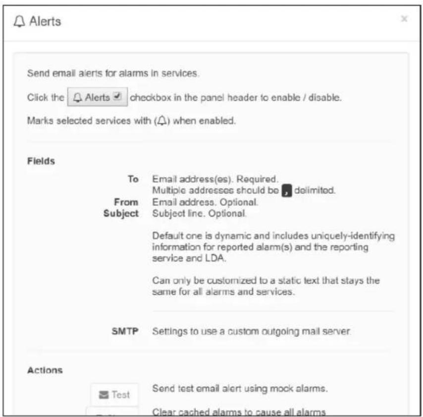
The field expands to enter an email address as well as define the From email and Subject line if desired.

To:
The email addresses receiving the email alerts should be entered into this field. Multiple addresses should be separated with a comma as shown.
From:
If the default sender creates confusion for the party (parties) receiving the emails it can be changed to reflect the desired information.
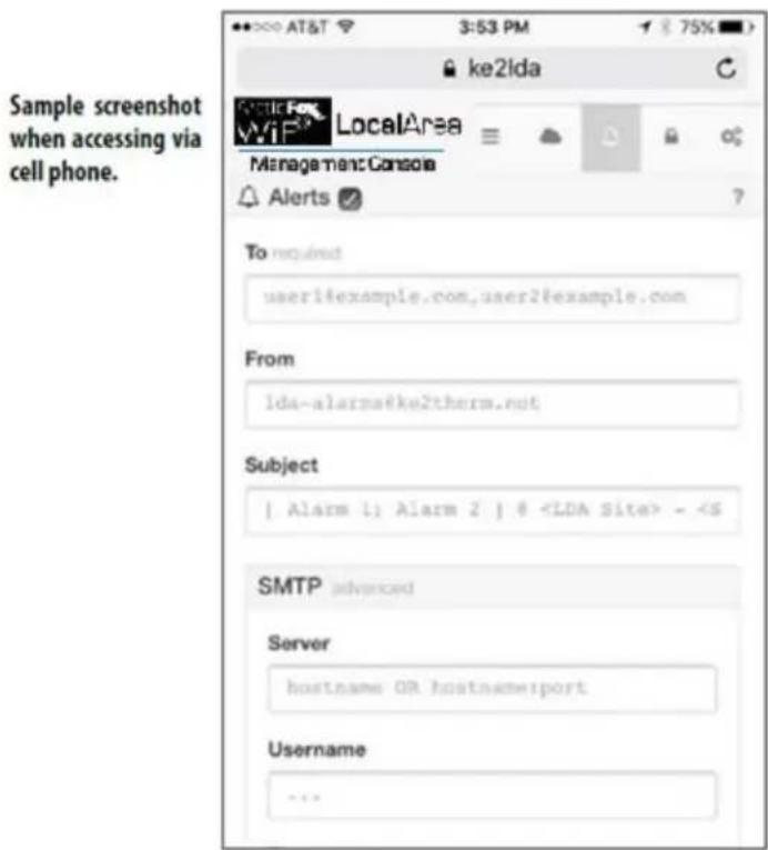
When customers choose to use their own email server as the email relay, the SMTP section should be expanded. It can be expanded by clicking anywhere on the gray bar.
Once expanded, the appropriate information should be entered from the customer supplied email server.
- KOLPAK/RDI REFRIGERATION SYSTEM INSTALLATION & OPERATION MANUAL
- WELBILT
- TABLE OF CONTENTS
- GENERAL SAFETY INFORMATION
- WARNING
- CAUTION
- SAFETY NOTICES
- RECEIVING INSPECTION
- LOCATING AND MOUNTING CONDENSING UNIT
- GENERAL GUIDELINES
- GENERAL GUIDELINES - CONDENSING UNIT LOCATING AND MOUNTING (CONTINUED)
- CLEARANCE REQUIREMENTS
- CLEARANCE REQUIREMENTS (CONTINUED)
- LOCATING AND MOUNTING EVAPORATOR COIL
- GENERAL GUIDELINES - LOCATING AND MOUNTING EVAPORATOR COIL (CONTINUED)
- WIRING
- GENERAL REQUIREMENTS
- CLEANLINESS
- OIL TRAPS
- PRESSURE REGULATING-RELIEF VALVES
- PRE-CHARGED LINES AND QUICK CONNECTS
- PRE-CHARGED LINES AND QUICK CONNECTS (CONTINUED)
- LEAK TESTING
- LEAK TESTING "PR" MODEL SYSTEMS
- LEAK TESTING "PC" MODEL SYSTEMS
- LEAK TESTING "PCL" MODEL SYSTEMS
- EVACUATION OF "PR" MODEL SYSTEMS
- EVACUATION OF "PC" MODEL SYSTEMS
- EVACUATION OF "PCL" MODEL SYSTEMS
- REFRIGERANT CHARGING
- OPERATIONAL START-UP
- PRE-START CHECKS
- COMPRESSOR MOUNTS
- START-UP PROCEDURE (CONTINUED)
- COMPRESSOR SUPERHEAT
- EVAPORATOR SUPERHEAT
- EVAPORATOR SUPERHEAT (CONTINUED)
- THERMOSTATS (CONTINUED)
- SETPOINTS
- CUSTOM DEFROST SETUP
- ABBREVIATIONS
- STEP 1
- STEP 2
- STEP 3
- STEP 4
- EXAMPLES
- STEP 5
- EXAMPLE
- STEP 6
- STEP 7
- ELECTRIC DEFROST TIMER
- ELECTRIC DEFROST TIME CLOCK INSTRUCTIONS
- MAINTENANCE
- POLYOL ESTER (POE) LUBRICANTS
- POLYOL ESTER (POE) LUBRICANTS (CONTINUED)
- TROUBLESHOOTING CHARTS
- ARCTICFOX LOCAL AREA DASHBOARD & ALARMS (LDA)
- ARCTICFOX LDA KIT INCLUDES THE LDA & ACCESSORIES
- USING THE FLASH DRIVE FOR DATA LOGGING THE LDA
- FLASH DRIVE KIT
- ACCESSING THE LOCAL DASHBOARD
- HTTPS://AFLDA
- ALLOWING KOLPAK TO REMOTE ACCESS
- TO
- FROM
Brand : Kolpak
Model : Polar Pak PX7-128-CT
Category : Refrigerator