
RPMB364 - Projector Chief - Free user manual and instructions
Find the device manual for free RPMB364 Chief in PDF.


| Product Type | Projector Mount |
| Brand | Chief |
| Model | RPMB364 |
| Series | RPMX (RPMA/RPMB/RPMC) |
| Weight Capacity | 50 lbs (22.7 kg) |
| Installation Options | 1-1/2" NPT/NPSM threaded column; double 2"x4" wood stud cross bracing; concrete ceiling (min 8" thick); four #10-24 threaded rods |
| Adjustments | Pitch (vertical), Roll (horizontal), Yaw (rotation) with micro-adjustment screws |
| Compatibility | Chief SLM series interface brackets; Chief WM110S, WM120S, WM130S, WM210S, WM220S, WM230S, WM240S, WM210SI, WM220SI, WM230SI, WM240SI, SL220, LSB101 (sold separately) |
| Materials | Steel and aluminum |
| Safety Features | Locking lever, key lock, security screw |
| Tools Required | 5/32" hex key, #2 Phillips screwdriver, drill, 3/32" and 1/4" drill bits, hammer, open-ended wrench |
| Mounting Hardware Included | Interface bracket (SLM series), security screws |
| Mounting Hardware Not Included | Threaded extension column, lag bolts, washers, concrete anchors, threaded rods, jam nuts |
| Structural Support Requirement | Must support 5 times total weight of equipment |
| Indoor Use Only | Yes (not for outdoor use) |
| Dimensions | Not specified in manual; varies with installation |
| Weight | Not specified |
| Power | None (mechanical mount) |
| Maintenance | Periodic inspection of fasteners and structural integrity |
| Repairability | Manufacturer recommends return for repair if damaged |
| Warranty | Refer to manufacturer |
Frequently Asked Questions - RPMB364 Chief
User questions about RPMB364 Chief
0 question about this device. Answer the ones you know or ask your own.
Ask a new question about this device
Download the instructions for your Projector in PDF format for free! Find your manual RPMB364 - Chief and take your electronic device back in hand. On this page are published all the documents necessary for the use of your device. RPMB364 by Chief.
USER MANUAL RPMB364 Chief
INSTALLATION INSTRUCTIONS
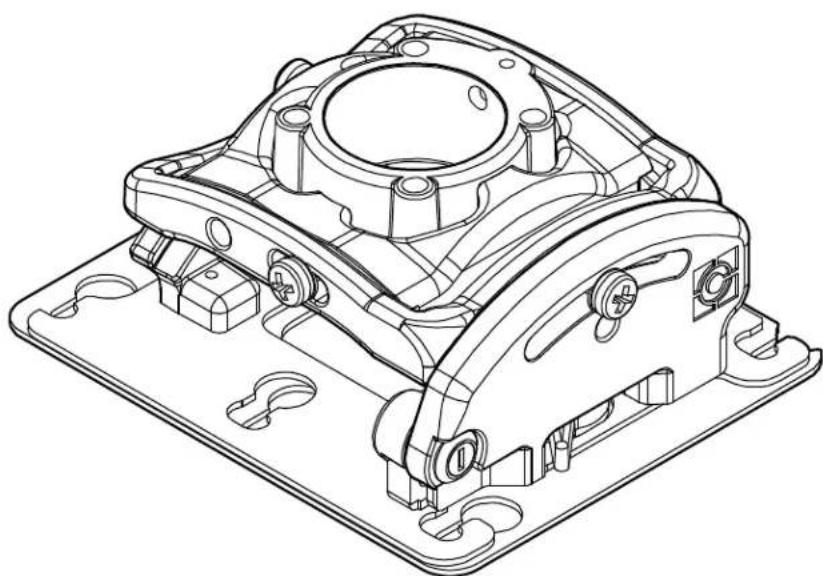
RPA Elite Series Projector Mounts
NOTE: RPMA, RPMB, and RPMC models are included in these installation instructions. Throughout these instructions "RPMX" is used to designate all of the models covered by these instructions.
DISCLAIMER
Milestone AV Technologies and its affiliated corporations and subsidiaries (collectively "Milestone") intend to make this manual accurate and complete. However, Milestone makes no claim that the information contained herein covers all details, conditions or variations, nor does it provide for every possible contingency in connection with the installation or use of this product. The information contained in this document is subject to change without notice or obligation of any kind. Milestone makes no representation of warranty, expressed or implied, regarding the information contained herein. Milestone assumes no responsibility for accuracy, completeness or sufficiency of the information contained in this document.
Chief® is a registered trademark of Milestone AV Technologies. All rights reserved.
DEFINITIONS
MOUNTING SYSTEM: A MOUNTING SYSTEM is the primary Chief product to which an accessory and/or component is attached.
ACCESSORY: AN ACCESSORY is the secondary Chief product which is attached to a primary Chief product, and may have a component attached or setting on it.
COMPONENT: A COMPONENT is an audiovisual item designed to be attached or resting on an accessory or mounting system such as a video camera, CPU, screen, display, projector, etc.

WARNING: A WARNING alerts you to the possibility of serious injury or death if you do not follow the instructions.

CAUTION: A CAUTION alerts you to the possibility of damage or destruction of equipment if you do not follow the corresponding instructions.

IMPORTANT SAFETY INSTRUCTIONS

WARNING: Failure to read, thoroughly understand, and follow all instructions can result in serious personal injury, damage to equipment, or voiding of factory warranty! It is the installer's responsibility to make sure all mounting systems are properly assembled and installed using the instructions provided.

WARNING: Failure to provide adequate structural strength for this mounting system can result in serious personal injury or damage to equipment! It is the installer's responsibility to make sure the structure to which this mounting system is attached can support five times the combined weight of all equipment. Reinforce the structure as required before installing the mounting system.

WARNING: Exceeding the weight capacity can result in serious personal injury or damage to equipment! It is the installer's responsibility to make sure the combined weight of all components attached to the RPMX does not exceed 50 lbs (22.7 kg).
- The weight capacity of the RPMX may be LIMITED to the lowest weight capacity of any other mounting systems/accessories located between the RPMX and the supporting structure!

WARNING: Use this mounting system only for its intended use as described in these instructions. Do not use attachments not recommended by the manufacturer.

WARNING: Never operate this mounting system if it is damaged. Return the mounting system to a service center for examination and repair.

WARNING: Do not use this mounting system outdoors.
IMPORTANT ! : The RPMX mounting system is designed to be:
- mounted to a 1-1/2" NPT or NPSM following ANSI/ASME B1.20.1 (Schedule 40, 0.154" minimum thickness aluminum - ASTM B221) threaded extension column;
- mounted to double 2" x 4" wood stud cross bracing (1-1/2" on center) between two 2" x 4" ceiling joists with a maximum drywall covering of 5/8";
- mounted to a concrete ceiling with a minimum thickness of 8" and a maximum drywall covering of 5/8"; or
- suspended from four #10-24 grade ASTM A307 or better threaded rods (not included) which are secured to Unistrut®, angle or channel assembly overhead structural members (trusses or I-beams) by #10-24 grade ASTM A307 or better jam nuts (not included).
NOTE: RPMA / RPMB / RPMC Series may be used with Listed Chief models WM110S, WM120S, WM130S, WM210S, WM220S, WM230S, WM240S, WM210SI, WM220SI, WM230SI, WM240SI, SL220 and LSB101 (not included).
--SAVE THESE INSTRUCTIONS--
DIMENSIONS
DIMENSIONS: INCHES



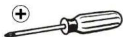
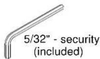
TOOLS REQUIRED FOR INSTALLATION

3/32" (2.4mm) dia. (wood)
1/4" (6.4mm) dia. (concrete)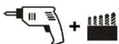

PARTS


A (1) [RPMA/-B/-C]

B (1) [Example of SLM bracket]
LEGEND
 | Tighten FastenerSerrez les fixationsSerrare il fissaggioBefestigungsteil festziehenApretar elemento de fijaciónBevestiging vastdraaienApertar fixador |  | Pencil MarkMarquage au crayonSegno a matitaStiftmarkierungMarcar con lápizPotloodmerktekenMarcar com lápis |
 | Loosen FastenerDesserrez les fixationsAllentare il fissaggioBefestigungsteil lösenAflojar elemento de fijaciónBevestiging losdraaienDesapertar fixador |  | Drill HolePercez un trouPraticare un foroBohrlochPerforarGat borenFazer furo |
 | Phillips ScrewdriverTournevis à pointe cruciformeCacciavite a stellaKreuzschlitzschraubendreherDestornillador PhillipsKruiskopschroevendraaierChave de fendas Phillips |  | AdjustAjusterRegolareEinstellenAjustarAfstellenAjustar |
 | Hex-Head WrenchClé à tête hexagonaleChiave esagonaleSechskantschlüsselLlave de cabeza hexagonalZeskantsleutelChave de cabeça sextavada |  | HammerMartilloHammerMarteloMartelloHamerMarteau |
 | Open-Ended WrenchClé à fourcheChiave a punte aperteGabelschlüsselLlave de bocaSteeksleutelChave de bocas |  | Target of ProjectorPunto de enfoque del proyectorZiel des ProjektorsMira do projectorPunto di proiezioneDoel van de projectorCible du projecteur |
 | By HandÀ la mainA manoVon HandA manoMet de handCom a mão |  | Security WrenchClé de sécuritéChiave di sicurezzaSicherheitsschlüsselLlave de seguridadVeiligheidssleutelChave de segurança |
PREPARATION
Locate Mounting Site

WARNING: IMPROPER INSTALLATION MAY LEAD TO PROJECTOR MOUNT FALLING CAUSING SEVERE PERSONAL INJURY OR DAMAGE TO EQUIPMENT! It is the installer's responsibility to make certain the structure to which the projector mount is being mounted is capable of supporting five times the weight of the projector mount and all attached equipment. Reinforce the structure as required before installing the projector mount.
- Determine required position of the RPMX projector mount.
- Determine required distance of the projector mount from the screen using the projector specifications.
NOTE: Proceed to Installing to 1-1/2" Threaded Extension Column, Installing to Wood Framework, Installing to Concrete Ceiling, or Installing to Threaded Rod section, as appropriate.
INSTALLATION
Installing to 1-1/2" Threaded Extension Column
- Install 1-1/2" NPT or NPSM following ANSI/ASME B1.20.1 (Schedule 40, 0.154" minimum thickness steel or aluminum - ASTM B221) threaded extension column (not included) into threaded collar until tight, with a minimum of four threads engaged.
- Thread RPMX projector mount (A) onto the threaded extension column (not included) until hand tight.
- Turn RPMX clockwise or counter-clockwise until front of mount is facing target.
IMPORTANT! When RPMX is properly positioned, the set screw access hole should be pointing directly at target, or 180° AWAY from target.
- Secure RPMX to pipe by turning set screw with a 5/32" hex key until tight. (See Figure 1)

CAUTION: DO NOT OVERTIGHTEN! Over tightening of set screw can damage threads on pipe.
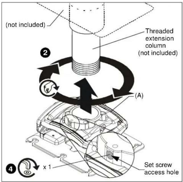
Figure 1
- Turn security screw (access from bottom of RPMX) (See Figure 2) using a Phillips screwdriver until set screw cannot be seen through set screw access hole in RPMX. (See Figure 1)
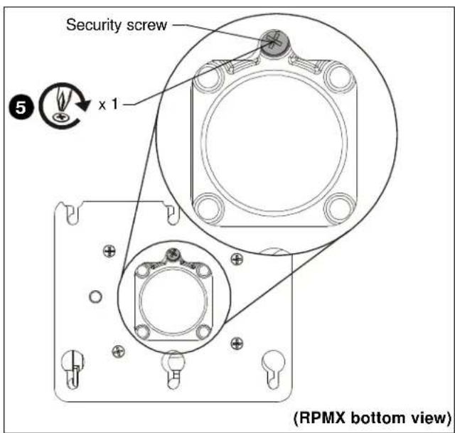
Figure 2
- Proceed to Installing Projector with Interface Bracket section.
Installing to Wood Framework (Joists)
- Using the RPMX as a guide, mark four mounting hole locations. (See Figure 3)
- Drill four 3/32" (2.4mm) dia. pilot holes to a depth of 1-3/4" (45mm) deep.

Figure 3
- Align four mounting holes in RPMX with four pilot holes. IMPORTANT! When RPMX is properly positioned, the set screw access hole should be pointing directly at target, or 180° AWAY from target.
- Secure RPMX to structure using four 1/4 x 3" ASTM A307, Grade A lag bolts (not included) and four 1/4" Grade 2 flat washers (not included). (See Figure 4)

Figure 4
- Proceed to Installing Projector with Interface Bracket section.
Installing to Concrete Ceiling

WARNING: The RPMX is designed to be mounted to a concrete ceiling with a minimum thickness of 8" and a maximum drywall covering of 5/8".
- Using the RPMX as a guide, mark four mounting hole locations on ceiling using a pencil or similar tool.
- Drill four 1/4" (6.4mm) dia. pilot holes to a depth of 2-1/2" (64mm) deep. (See Figure 5)

Figure 5
- Align four mounting holes in RPMX with four pilot holes.
IMPORTANT ! : When RPMX is properly positioned, the set screw access hole should be pointing directly at target, or 180° AWAY from target.

WARNING: Anchors (not provided) must be installed into structurally sound solid concrete. Installation into hollow concrete block, mortar, or concrete that exhibits cracking, spalling, or other defects may result in failure of anchor and serious personal injury or damage to equipment.
- Install four Toggler AF6 Alligator concrete anchors (not included) by inserting into pilot holes and hammering in until flush with mounting surface.
- Secure RPMX to structure using four 1/4" Grade 2 flat washers and four 1/4" x 3" ASTM A307, Grade A lag bolts (not included). (See Figure 6)

Figure 6
Installing to Threaded Rod
NOTE: The RPMX projector mount may be suspended from four #10-24 grade ASTM A307 or better threaded rods (not included) which are secured to unistrut, angle or channel assembly overhead structural members (trusses or I-beams) by #10-24 grade ASTM A307 or better jam nuts (not included).
- Secure one end of each of the four threaded rods (not included) to the structural member.
- Install four #10-24 jam nuts (not included) onto each threaded rod.
- Install RPMX onto threaded rods, inserting the rods into the four holes on top of the RPMX.
NOTE: Hole in the RPMX allows socket wrench access without unit disassembly.
- Secure the threaded rods to the RPMX with #10-24 jam nuts (not included) and 1/4" washers (not included). (See Figure 7)

Figure 7
- Proceed to Installing Projector with Interface Bracket section.
PROJECTOR INSTALLATION
IMPORTANT! Model RPMX uses optional Chief "SLM" Series interface brackets. See Parts drawing.
- Attach projector to interface bracket (B) using installation instructions and hardware included with the interface bracket.
NOTE: Security screws can be substituted when mounting Interface bracket to projector by using the hardware and installation instructions in the All-Points Security Kit (included with interface bracket).
Installing Projector with Interface Bracket
- Orient projector with interface bracket.
- Lift projector so that screws with thumb nuts are aligned with mounting slots in mount base. (See Figure 8)
- Slide projector with mounting bracket into mounting slots in mount base until screws are seated against the back of mounting slots.

WARNING: IMPROPER INSTALLATION CAN LEAD TO PROJECTOR FALLING RESULTING IN SERIOUS PERSONAL INJURY OR DAMAGE TO EQUIPMENT. Make certain mounting slots in projector mount base slide under thumb screws and that screws are seated in the back of slots.
![[Locked] [Unlocked] (A) Mounting slots Locking lever 3 6 Lock 2 (Mounting structure not shown for clarity)](/content/2026/06/1247941/images/00974da55299943e1bdf7f0854e2939ceba6a060ce4e3086b4734c32d5dd5a67.jpg)
Figure 8
- Verify mounting screws are properly seated in mounting slots in projector mount base.
- Move locking lever to "LOCKED" position. (See Figure 8)
- Insert key into lock and turn to secure projector to RPMX.
- Route all cables, as required.
ADJUSTMENTS
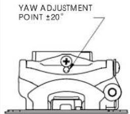
The RPMX projector mount can be adjusted for pitch (vertical elevation), roll (horizontal tilt), and yaw (rotation).

WARNING: OVER-LOOSENING OR REMOVAL OF HARDWARE MAY RESULT IN PERSONAL INJURY OR SERIOUS DAMAGE TO EQUIPMENT! RPMX projector mount and hardware is to be loosened only enough to allow for necessary movement.
YAW Adjustment (Rotation)
- Loosen YAW adjustment locking screw using a #2 Phillips screwdriver. (See Figure 9)
- Turn YAW micro-adjustment screw right or left using a #2 Phillips screwdriver until image is properly aligned on target.
- Tighten YAW adjustment locking screw using a #2 Phillips screwdriver.
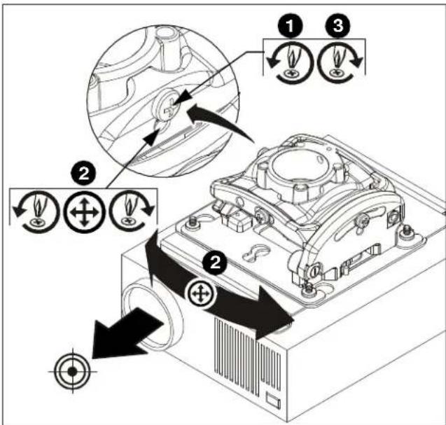
Figure 9
Pitch Adjustment (Vertical Elevation)
- Loosen PITCH adjustment locking screw using a #2 Phillips screwdriver. (See Figure 10)
- Turn the PITCH micro-adjustment screw right or left using a #2 Phillips screwdriver until the image is properly aligned on the target.
- Tighten the PITCH adjustment locking screw using a #2 Phillips screwdriver.
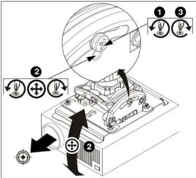
Figure 10
Roll Adjustment (Horizontal Tilt)
- Loosen the ROLL adjustment locking screw using a #2 Phillips screwdriver. (See Figure 11)
- Turn the ROLL micro-adjustment screw right or left using a #2 Phillips screwdriver until the image is properly aligned on the target.
- Tighten the ROLL adjustment locking screw using a #2 Phillips screwdriver.

Figure 11
RPMA/RPMB/RPMC Series
Installation Instructions


- INSTALLATION INSTRUCTIONS
- RPA ELITE SERIES PROJECTOR MOUNTS
- DISCLAIMER
- DEFINITIONS
- IMPORTANT SAFETY INSTRUCTIONS
- SAVE THESE INSTRUCTIONS
- DIMENSIONS
- TOOLS REQUIRED FOR INSTALLATION
- PARTS
- PREPARATION
- LOCATE MOUNTING SITE
- INSTALLATION
- INSTALLING TO 1-1/2" THREADED EXTENSION COLUMN
- INSTALLING TO WOOD FRAMEWORK (JOISTS)
- INSTALLING TO CONCRETE CEILING
- INSTALLING TO THREADED ROD
- PROJECTOR INSTALLATION
- INSTALLING PROJECTOR WITH INTERFACE BRACKET
- ADJUSTMENTS
- YAW ADJUSTMENT (ROTATION)
- PITCH ADJUSTMENT (VERTICAL ELEVATION)
- ROLL ADJUSTMENT (HORIZONTAL TILT)
Brand : Chief
Model : RPMB364
Category : Projector