Atdec AF-AT-W-P - Wall mount for screen

AF-AT-W-P - Wall mount for screen Atdec - Free user manual and instructions

Find the device manual for free AF-AT-W-P Atdec in PDF.

📄 4 pages English EN Download 💬 AI Question 10 questions ⚙️ Specs
Notice Atdec AF-AT-W-P - page 1
Pick your language and provide your email: we'll send you a specifically translated version.
Product Type Wall Mount for Screen
Brand Atdec
Model AF-AT-W-P
Compatible VESA Patterns 75x75 mm, 100x100 mm
Maximum Screen Size 32 inches
Maximum Weight Capacity 25 kg (55 lbs)
Material Heavy-duty steel
Finish Black powder coated
Orientation Fixed (non-tilting)
Mounting Type Wall mounted
Wall Plate Dimensions 300 x 150 x 20 mm
Distance from Wall 20 mm
Level Adjustment Yes, ±2 degrees
Included Hardware Screws, anchors, and spacers for most wall types
Safety Designed to meet UL safety standards
Installation Professional installation recommended for concrete or brick walls
Cleaning Instructions Wipe with a dry cloth; avoid solvents
Spare Parts Contact Atdec customer service for replacement screws or brackets
Warranty 5 years limited warranty
Package Contents Wall mount, installation kit, manual

Frequently Asked Questions - AF-AT-W-P Atdec

What VESA patterns does the Atdec AF-AT-W-P support?
The mount supports standard VESA patterns of 75x75 mm and 100x100 mm, which cover most monitors up to 32 inches.
What is the maximum weight capacity of this wall mount?
The maximum weight capacity is 25 kg (55 lbs). Always ensure your monitor does not exceed this limit.
Is the mount fixed or tilting?
The AF-AT-W-P is a fixed wall mount with no tilt or swivel. It keeps the screen flat against the wall.
Can I install this mount on drywall?
Yes, but you must use appropriate wall anchors (included) and ensure the drywall can support the weight. For heavy monitors, mount onto wall studs.
What tools are needed for installation?
You will need a drill, a Phillips screwdriver, a level, and a stud finder (for drywall). Basic DIY skills are recommended.
Are installation instructions included?
Yes, a user manual with step-by-step instructions and diagrams is included in the package.
What is the distance from the wall to the back of the screen?
The mount keeps the screen approximately 20 mm away from the wall, giving a slim profile.
Can I use this mount for a TV?
Yes, as long as the TV is within the VESA pattern and weight limits. TVs up to 32 inches with standard VESA are compatible.
How do I clean the wall mount?
Use a dry or slightly damp cloth to wipe the mount. Do not use harsh chemicals or abrasive cleaners.
What should I do if I lose the mounting screws?
You can order replacement screw kits from Atdec customer support or use standard M4/M6 screws with appropriate length (consult manual).

User questions about AF-AT-W-P Atdec

0 question about this device. Answer the ones you know or ask your own.

Ask a new question about this device

The email remains private: it is only used to notify you if someone responds to your question.

No questions yet. Be the first to ask one.

Download the instructions for your Wall mount for screen in PDF format for free! Find your manual AF-AT-W-P - Atdec and take your electronic device back in hand. On this page are published all the documents necessary for the use of your device. AF-AT-W-P by Atdec.

USER MANUAL AF-AT-W-P Atdec

Wall Mounted Monitor Arm
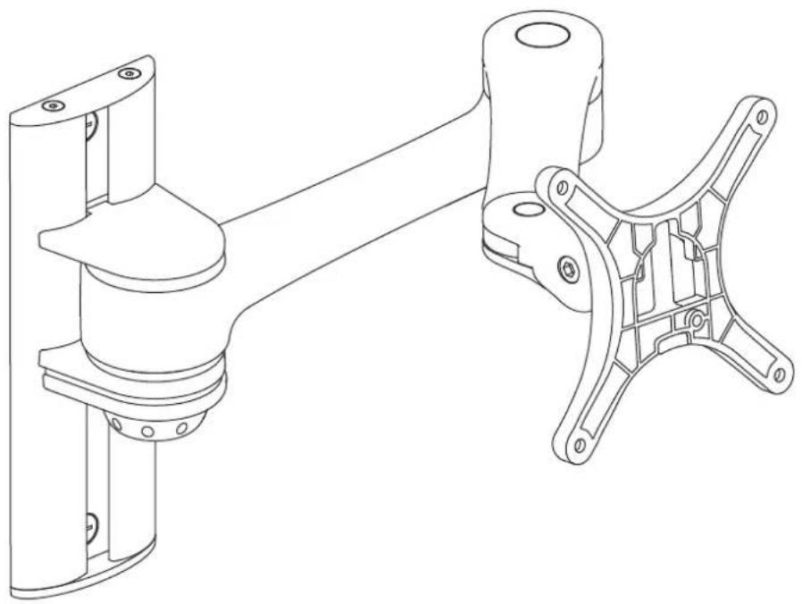
Atdec AF-AT-W-P - Wall Mounted Monitor Arm - 1

natural_image Technical line drawing of a mechanical assembly with two views (top and side), no text or symbols present.

COMPONENT CHECKLIST
A Arm Assem (x1) B C

B VESA head (x1)
C End Cap (x1)

D Wall Plate (x1)
Atdec AF-AT-W-P - Wall Mounted Monitor Arm - 3

Atdec AF-AT-W-P - Wall Mounted Monitor Arm - 4
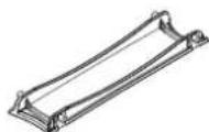
E Primary arm cable cover (x1)

Atdec AF-AT-W-P - Wall Mounted Monitor Arm - 5
F Secondary arm cable cover (x1)

Atdec AF-AT-W-P - Wall Mounted Monitor Arm - 6

Atdec AF-AT-W-P - Wall Mounted Monitor Arm - 7
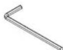
G 2.5mm Allen key (x1)

Atdec AF-AT-W-P - Wall Mounted Monitor Arm - 8
I Nylon Anchor Plug (x2)

Atdec AF-AT-W-P - Wall Mounted Monitor Arm - 9
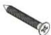
J Countersunk Screws M4 x 12mm (x2)

Atdec AF-AT-W-P - Wall Mounted Monitor Arm - 10
K Countersunk Screws M6 x 50mm (x2)

Atdec AF-AT-W-P - Wall Mounted Monitor Arm - 11
L Mounting screws M4 x 10mm (x4)

Atdec AF-AT-W-P - Wall Mounted Monitor Arm - 12
M Mounting screws M4 x 12mm (x4)

Atdec AF-AT-W-P - Wall Mounted Monitor Arm - 13
N Mounting screws M4 x 16mm (x4)

Atdec AF-AT-W-P - Wall Mounted Monitor Arm - 14
Security Screw M4 x 16mm (x1)

Walk

REQUIRED TOOLS

  • Power Drill
  • Drill Bit
    • Phillips Head Screwdriver

WEIGHT RANGE

Atdec AF-AT-W-P - WEIGHT RANGE - 1

0 - 8kg (0 - 17.6lbs)

IMPORTANT INFORMATION

! Please ensure this product is installed as per these installation instructions.
! The manufacturer accepts no responsibility for incorrect installation.

1. Position Wall Plate

As a guide, it is recommended that the bottom of the Wall Plate be positioned approximately 140mm (5 1/2") above the desktop.

Note: The wall-mounted arm provides vertical adjustment of 128mm. 128mm (5°) 140mm (5 1/2")

2. Choose the appropriate installation procedure depending on your wall type

Masonry
Nylon Anchors 8mm (5/16") Hole M6 x 50mm Countersunk Screw Wall Plate

Timber Stud
Timber Stud 5.5mm (1/4") Hole M6 x 50mm Countersunk Screw Wall Plate

3. Mount Arm Assembly

3.1 Unlock the Locking Dial before inserting the Arm Assembly into the Wall Plate
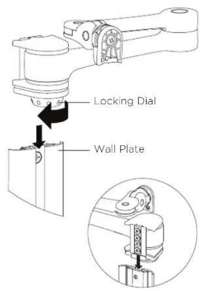
Locking Dial Wall Plate

3.2 Slide the Arm Assembly to the preferred height and lock to secure the arm
Locking Dial

3.3 Secure the End Cap with the supplied M4x12mm Countersunk Screws and 2.5mm Allen Key
M4x12mm Countersunk Screw End Cap 2.5mm Allen Key

4. Install VESA monitor head
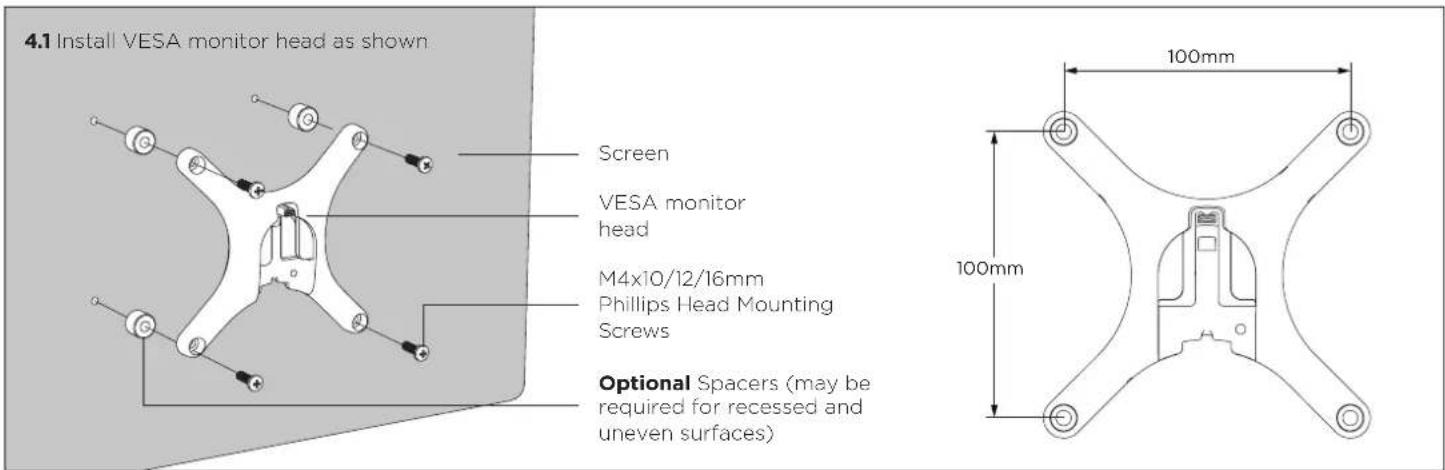
4.1 Install VESA monitor head as shown Screen VESA monitor head M4x10/12/16mm Phillips Head Mounting Screws Optional Spacers (may be required for recessed and uneven surfaces) 100mm 100mm

5. Mounting Monitor

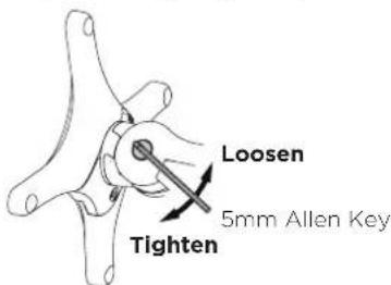
5.1 Insert VESA monitor head into the receptacle in the Arm Assembly VESA monitor head Arm Assembly 5.2 OPTIONAL SECURITY SCREW Ensure the Monitor is supported, then loosen the Monitor head screw with the 5mm Allen Key and tilt screen up before installing the M4 x 16mm Security Screw into the Security Screw hole Monitor head screw Security Screw Hole M4 x 16mm Security Screw Note: Support Screen when adjusting tilt. Loosen Tighten Phillips Head Screwdriver 5mm Allen Key

6. Adjusting Height

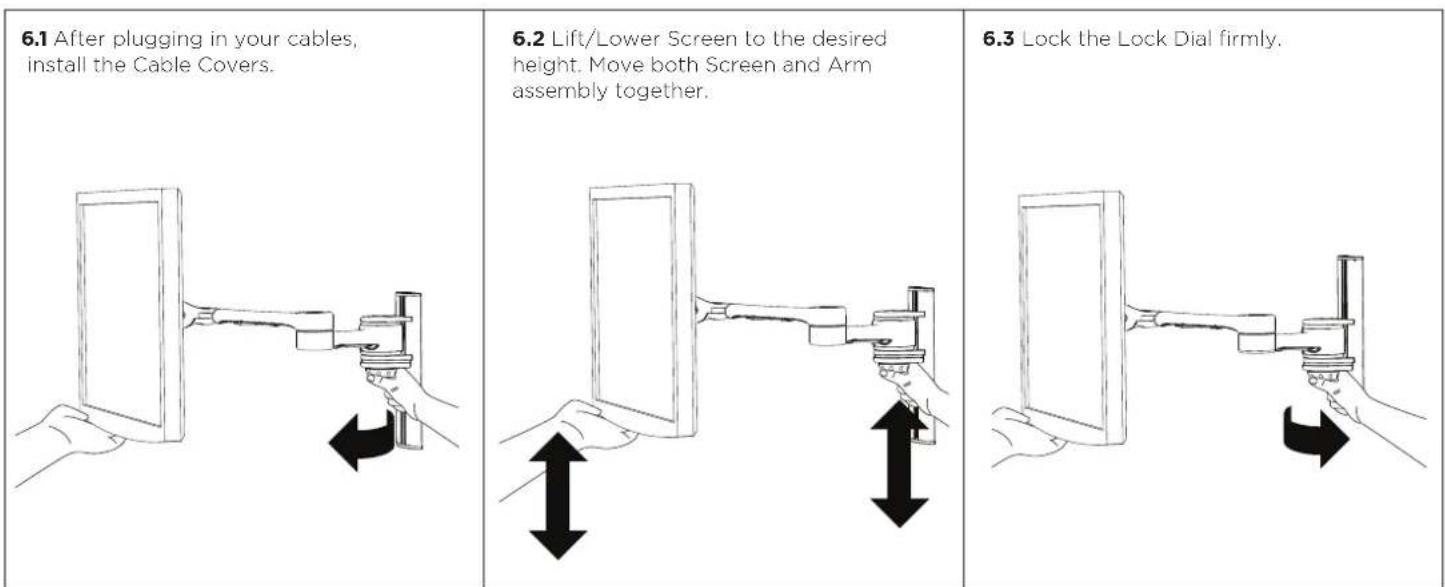
6.1 After plugging in your cables, install the Cable Covers. 6.2 Lift/Lower Screen to the desired height. Move both Screen and Arm assembly together. 6.3 Lock the Lock Dial firmly.

7. Cable Management

7.1 After plugging in your cables, install the Cable Covers. Insert Cable Covers up into Lock Slots.

Lock Slot

7.2 Push Cable Covers away from Elbow Joint to secure in place.

'click' 'click' Elbow Joint

7.3 Cable Clips and Cable Stops can be installed to further manage cables.

Note: Ensure enough cable slack is given to allow for movement.

8. Adjusting the Display Bracket

Portrait/ Landscape
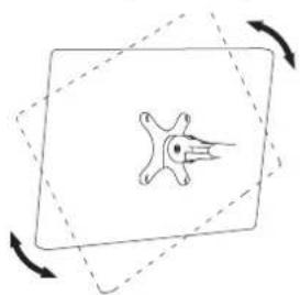
Atdec AF-AT-W-P - Adjusting the Display Bracket - 1

natural_image Simple line drawing of a stylized fish inside a rounded rectangle with dashed arrows indicating rotation (no text or symbols)

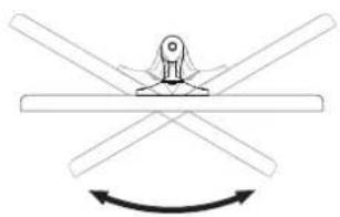
Tilt (Screen angle up/down)
Loosen 5mm Allen Key Tighten

Pan (Screen angle left/right)
Atdec AF-AT-W-P - Adjusting the Display Bracket - 3

natural_image Diagram of a mechanical or electrical component with intersecting rods and a central knob, showing rotational motion (no text or symbols)

No Allen Key necessary No Allen Key necessaryport Screen when adjusting tilt.

Manual assistant
Powered by Anthropic
Waiting for your message
Product information

Brand : Atdec

Model : AF-AT-W-P

Category : Wall mount for screen